

Page 1

COPIER(OPTION) : SF-A18/A57
Date
:
Aug. 24, 1998
1. ESTABLISHMENT OF PARTS CARRIED OUT AS ACTION TO DIMINISH
MOVEMENT NOISE OF THE COOLING FAN.
2. ESTABLISHMENT OF REPLACEMENT PARTS CARRIED OUT IN
ACCORDANCE WITH A HALT IN PRODUCTION.
No. : SP-2319
1. Establishment of parts carried out as action to diminish movement noise of the
cooling fan.
1.Model Name: SF-A18/A57
2.General: There were some changes in parts such as the PBA control PWB which were reported
in Technical Report No. SP-2255 as a measure to diminish the movement noise of the
cooling fan, but in accordance with a demand from the markets the changed parts have
been established as a kit and are now offered as a service part.
Please refer to the explanation below for details concerning the sequence of the
changes.
3.Sequence: (Articles included in the changed parts) 0CW2224K214// (PBA-TH assembled kit)
0CW2224K213//(PBA-TH)
0CW385680//// (Plastic bag A(074))
0CW2224P436// (Th lead wire 4)
(Sequence of changed parts)
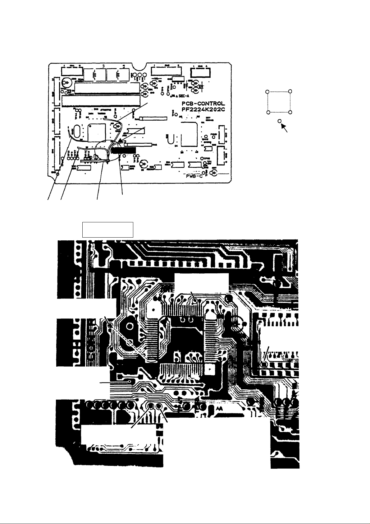
(1) The pattern of the PWB is cut (marked portions of the diagram shown below)
Soldered face
Pattern cut
Determine the relevant section using
this corner portion as a marker.
SHARP CORPORATION Reprography Division
1/4
Green
C
Page 2

(2) Suck out the solder of the through hole
(Through holes No. 1 through No. 4)
Through hole No. 2
Part face
Through hole No. 1
Through hole No. 4
Through hole No. 3
2/4
Page 3
Jumper wire (red)
(No. 2 Hole)
(3) Arrangements of the thermostat PWB.
Jumper wire (red)
Jumper wire (black)
Thermostat PWB
TP40 (No.3 Hole)
TP10 (No.4 Hole)
Jumper wire
(blue)
(No.1 Hole)
Secured by holt melt
Connections are secured by soldering (refer
to the figure for details)
1) Connect the accessory red jumper wire.
2) Connect the black jumper wire from the
thermostat PWB to the leg of the PSW1.
Diagram as seen from
the part face.
Connect to this location.
3) Connect the blue jumper wire from the
thermostat PWB to the IC11, 63 pin.
4) Connect the red jumper wire from the
thermostat PWB to the IC2, 28 pin.
5) Connect the thermostat PWB by inserting it
into the TP40, TP10 positions.
6) Gather the 3 wires protruding from the
thermostat PWB and secure them by hot
melt.
Part face
Jumper wire (red)
Connect IC 11, 20 pin with
through hole No. 2
Jumper wire (black)
From the thermostat PWB.
Connect to the leg of the
PSW1.
Connect the connector legs of the
thermostat PWB to TP40.
Through hole No. 3
Jumper wire (blue)
From the thermostat PWB
Through hole No. 1
Jumper wire (red)
From the thermostat
PWB.
Connect the connector legs of
the thermostat PWB to TP10.
Through hole No. 4
3/4
Page 4
(4) Check of the arrangements of the thermostat PWB.
1) After the cut of the pattern has been carried out, check the conductance with a tester
to confirm that the cut has been properly made.
2) After the check of the arrangements of the thermostat PWB has been carried out,
check the conductance of the legs of the jumper wire (blue) between the thermostat
PWB and the CPU 63 pin.
(5) Check of the arrangements of the actual machine.
1) Check the blinking of the control PWB after turning the power supply ON.
2) Check the operation of the tray sensor.
2. Establishment of replacement parts carried out in accordance with a halt in
production.
1.Model Name: SF-D21
Blinking cycle: 1sec (If there is a malfunction, the blinking will occur at a cycle of 50 mm.)
The check should be carried out through machine simulation 2-2.
2.General: There was a halt in the production of the transistor used in the desk main PWB. In
accordance with this change the establishment of a replacement part has been carried
out.
3.Action: Running change from 1998 mid-June production.
Ref.
Model
No.
SF-A18
1
SF-A57
SF-D21
(SF-2025
SF-2030)
2
SF-D21
(SF-2022
SF-2027)
<Interchange>
1. Interchangeable. 4. Not interchangeable.
2. Current type can be used in place of new type.
3. Current type cannot be used in place of new type.
Parts marked with " " is important for maintaining the safety of the set. Be sure to replace these parts with
specified ones for maintaining the safety and performance of the set.
Version P/G No.
name
---- ---- 0CW2224K214// AU PBA-TH kit ---- 6
59 -46
All
67 -46
New type cannot be used in place of current type.
New type can be used in place of current type.
Current parts New parts
Parts code Parts code
VS2SB1020-/-1 VS2SB1020A/-1 AK Transistor
Price
5. Interchangeable if replaced with same types of
related parts in use.
6. Others.
Parts name
rank
Effec-
tive time
'98/6
Running
change
change-
Inter-
Note
ability
1
4/4
 Loading...