

Page 1

COPIER : SF-2216 etc.
Date
:
Jun. 30, 1998
No. : SP-2292
MEASURE TO ALLEVIATE PROBLEMS OF JAMS IN THE
FUSING SECTION WHICH OCCUR DURING DOUBLE-SIDE
COPY OPERATIONS.
1.Model Name: SF-2116/1016/2118/1018/2020/1020/2216/1116
2.General: There have been problems of jams occurring in the fusing section during double-side
copy operations due to factors such as the quality of the copy paper and the humidity.
The following information concerning the action that has been carried out to alleviate
this problem is hereby reported.
Note:
Double-side copy operations carried out on the models listed above from the copy
paper cassette are not included in the specifications. As a result, even if the action
described in this Technical Report is carried out it does not mean that a change has
been carried out in the specifications (in other words, it does not mean that the
machines will be changed so that the function of double-side copy operations using the
copy paper cassette feed will have been made possible). As a result, when double-side
copy operations are carried out, it will be necessary to carry them out using manual
copy paper feed after correcting any curling of the copy paper, and it will therefore be
necessary to exercise caution to insure that there are no misunderstandings with the
customers.
<Symptoms>
There have been problems of jams occurring in front of the fusing section during
double-side copy operations.
<Cause>
When single side copies are made, curling sometimes occurs in the copy paper as due
to paper quality and humidity factors. If double-side copy operations are carried out
without correcting the curling of the copy paper, there is a possibility of jams occurring
in front of the fusing section.
SHARP CORPORATION Reprography Division
1/7
Green
C
Page 2
<Action>
The addition of the following parts listed below has been carried out. This action has
been carried out as a measure to improve the transport performance of the copy paper
in front of the fusing section.
<Parts name> <Parts code> <Q'ty>
Fusing front sheet A PSHEP4620FCZZ 1
Fusing front sheet B PSHEP4621FCZZ 1
Fusing front guide sheet PSHEP4622FCZZ 1
Fusing front upper guide PGIDH1758FCZZ 2
Upper guide sheet PSHEZ4454FCZZ 4
Screw XHBSD30P06000 2
Paper retainer sheet PSHEP4619FCZZ 1
<Attachment procedures>
<1> Disengage the fusing section from the machine.
<2> Remove the fixing screws (XHBSD30P06000) of the fusing unit and then remove
the fusing cover (PCOVQ1278FCZZ).
<3> Carry out attachment procedures of the new parts to the fusing cover.
Caution:
Please refer to the figure shown below for details concerning the attachment
standards. When attaching the new parts to the fusing cover the attachment
surfaces of the fusing cover should be carefully wiped with alcohol.
2/7
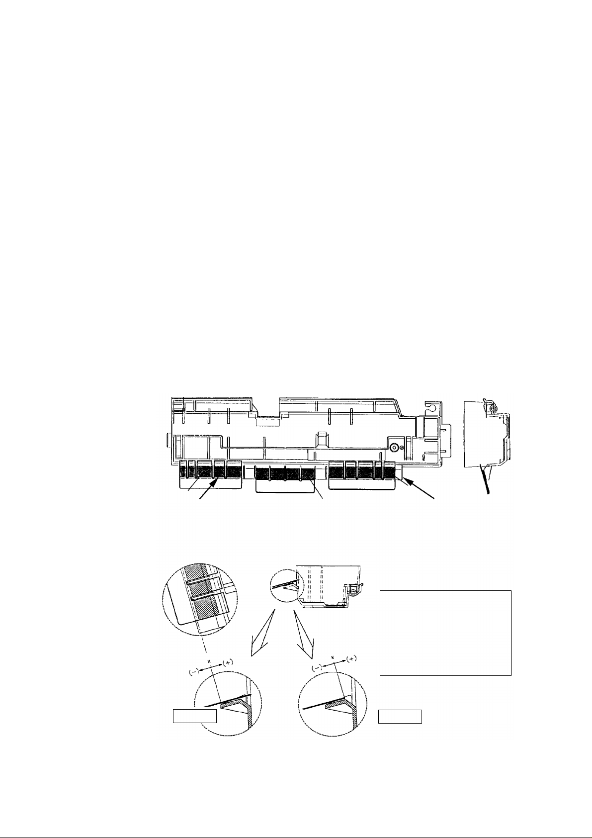
Fusing front sheet B
Care should be exercised so that fusing front sheet B, the fusing front guide
sheet, and fusing front sheet A do not ride up on the ribs of the fusing cover.
Standard
Figure 1
Fusing front guide sheet
Standard
Figure 2
Fusing front sheet A
The attachment size of each
sheet with regards to the
attachment standards marked
in the figures shown to the
right should be a maximum of
0 mm in the "+" direction and
0.5 mm in the "-" direction.
Page 3

Fusing front sheet A/B:
The fusing front sheets should be attached as shown in figure 1 with the end
of the ribs of the fusing cover being in alignment with the cut-away section R
of each sheet.
Fusing front guide sheet:
The fusing front guide sheet should be attached as shown in figure 2 with the
end of the fusing front guide sheet in alignment with the curved portion of the
fusing cover.
<4> The upper guide sheet should be attached to the fusing upper guide.
Please refer to the figure shown below for details concerning the attachment
standards.
Standard
Standard
Direction of
paper flow
Upper guide
sheet
Fusing upper
guide
Standard
Standard
Attachment differential:
0.5 mm in the "+" direction and 0 mm in the "-" direction from the attachment
standard.
Caution:
If there is any damage to the upper guide sheet in the section where the copy
paper passes through the copy paper can become snagged. After attachment
operations have been completed the surface of the section should be carefully
checked to make sure that there are no places where the copy paper can
become snagged.
<5> The fusing upper guide (Qty: 2) to which the upper guide sheets have been
attached should next be attached to the fusing upper frame. It is important to
note that the attachment holes in the fusing upper guide are long holes, and the
method of attachment for the AB series machines is different than that for the
inch series machines.
AB Series:
The fusing upper guide to be attached to the F side should be moved toward the
F side and then attached, and the fusing upper guide to be attached to the R
side should be moved toward the R side and then attached.
3/7
Page 4

Inch Series:
The fusing upper guide to be attached to the F side should be moved toward the
R side and then attached, and the fusing upper guide to be attached to the R side
should be moved toward the F side and then attached.
Fusing upper guide
F Side
Inch Series
AB Series
Inch Series
<6> The fusing cover should then be attached to the fusing unit.
Caution:
Care should be exercised to insure that the fusing front sheet A and the fusing
front sheet B do not become sandwiched in the gap between the fusing frame
and the fusing cover.
R Side
AB Series
4/7
NG
Fusing frame
Fusing cover
Fusing front sheet A/B
OK
<7> Attach the fusing unit to the machine by carrying out steps <1> and <2> in
reverse order.
<8> Remove the drum frame unit from the machine.
Page 5

<9> Attach the new parts to the bottom surface of the DR frame lower
(LFRM-0843FCZZ).
Caution:
Please refer to the figure shown below for details concerning the attachment
standards. (The diagram shown below depicts the drum frame unit from the
bottom direction.) When attaching the new parts to the DR frame lower the
attachment surfaces of the fusing cover should be carefully wiped with alcohol.
<10> Attach the drum frame unit to the machine.
3.Action: Field action only.
5/7
Page 6

Ref.
No.
Model
name
SF-2116
SF-2118
SF-1016
SF-1018
SF-2020
SF-1020
SF-2216
SF-1116
SF-2116
SF-2118
SF-1016
SF-1018
SF-2020
SF-1020
SF-2216
SF-1116
SF-2116
SF-2118
SF-1016
SF-1018
SF-2020
SF-1020
SF-2216
SF-1116
SF-2116
SF-2118
SF-1016
SF-1018
SF-2020
SF-1020
SF-2216
SF-1116
Version P/G No.
16
17
16
17
All
16
17
16
17
16
Current parts New parts
Parts code Parts code
PSHEP4620FCZZ
PSHEP4621FCZZ Fusing front sheet B
----
PSHEP4622FCZZ Fusing front guide sheet
PGIDH1758FCZZ AH Fusing front upper guide
Price
rank
Fusing front sheet A
AD
Parts name
Effec-
Inter-
tive
change-
time
ability
---- 6 ∗
Note
6/7
∗ Part for field action.
Page 7

Ref.
Model
No.
SF-2116
SF-2118
SF-1016
SF-1018
SF-2020
SF-1020
SF-2216
SF-1116
SF-2116
SF-2118
SF-1016
SF-1018
SF-2020
SF-1020
SF-2216
SF-1116
SF-2116
SF-2118
SF-1016
SF-1018
SF-2020
SF-1020
SF-2216
SF-1116
<Interchange>
1. Interchangeable. 4. Not interchangeable.
2. Current type can be used in place of new type.
3. Current type cannot be used in place of new type.
Parts marked with " " is important for maintaining the safety of the set. Be sure to replace these parts with
specified ones for maintaining the safety and performance of the set.
Version P/G No.
name
16
17
16
All
17
16
14
15
14
New type cannot be used in place of current type.
New type can be used in place of current type.
Current parts New parts
Parts code Parts code
PSHEZ4454FCZZ AD Upper guide sheet
---XHBSD30P06000 AA Screw
PSHEP4619FCZZ AD Paper retaining sheet
5. Interchangeable if replaced with same types of
related parts in use.
6. Others.
Price
rank
Parts name
Effec-
Inter-
tive
change-
time
ability
---- 6 ∗
Note
∗ Part for field action.
7/7
 Loading...