

Page 1
COPIER : SF-2040
Date
:
Dec. 1, 1997
[Service Information]
1.CORRECTION CARRIED OUT ON THE POSITION ADJUSTMENT
VALUE OF THE MAIN POLE OF THE DEVELOPER MAGNETIC ROLLER.
2.REPORT CONCERNING THE FUNCTIONS OF THE DIP SWITCHES.
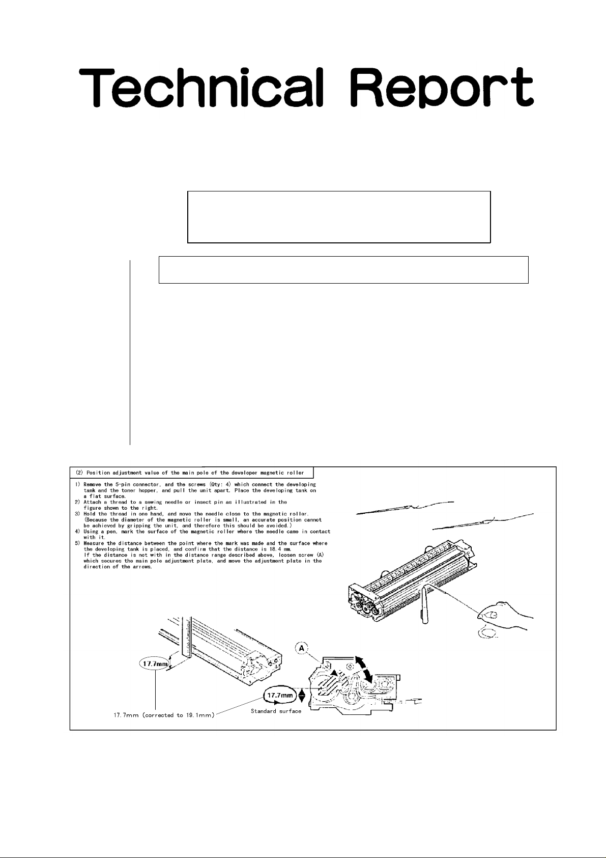
1. Correction carried out on the position adjustment value of the main pole of the
developer magnetic roller.
1.Model Name: SF-2040
2.General: There was an error in the service manual of the model listed above concerning the
position adjustment value of the main pole of the developer magnetic roller.
The correction of this error has been carried out and is hereby reported.
No. : SP-2195
3.Description: The error in the position adjustment value of the main pole of the developer magnetic
roller which is listed as (2) on page 7-1 of the service manual No. 1 for model SF-2040
has been corrected. 17.7 mm has been changed to 19.1 mm.
SHARP CORPORATION Reprography Division
1/9
Green
C
Page 2
2. Report concerning the functions of the DIP switches.
1.Model Name: SF-A15
2.General: The explanation of the functions of the DIP switches on the control PWB was
inadvertently omitted from the service manual of the models listed above.
The functions of the DIP switches are hereby reported.
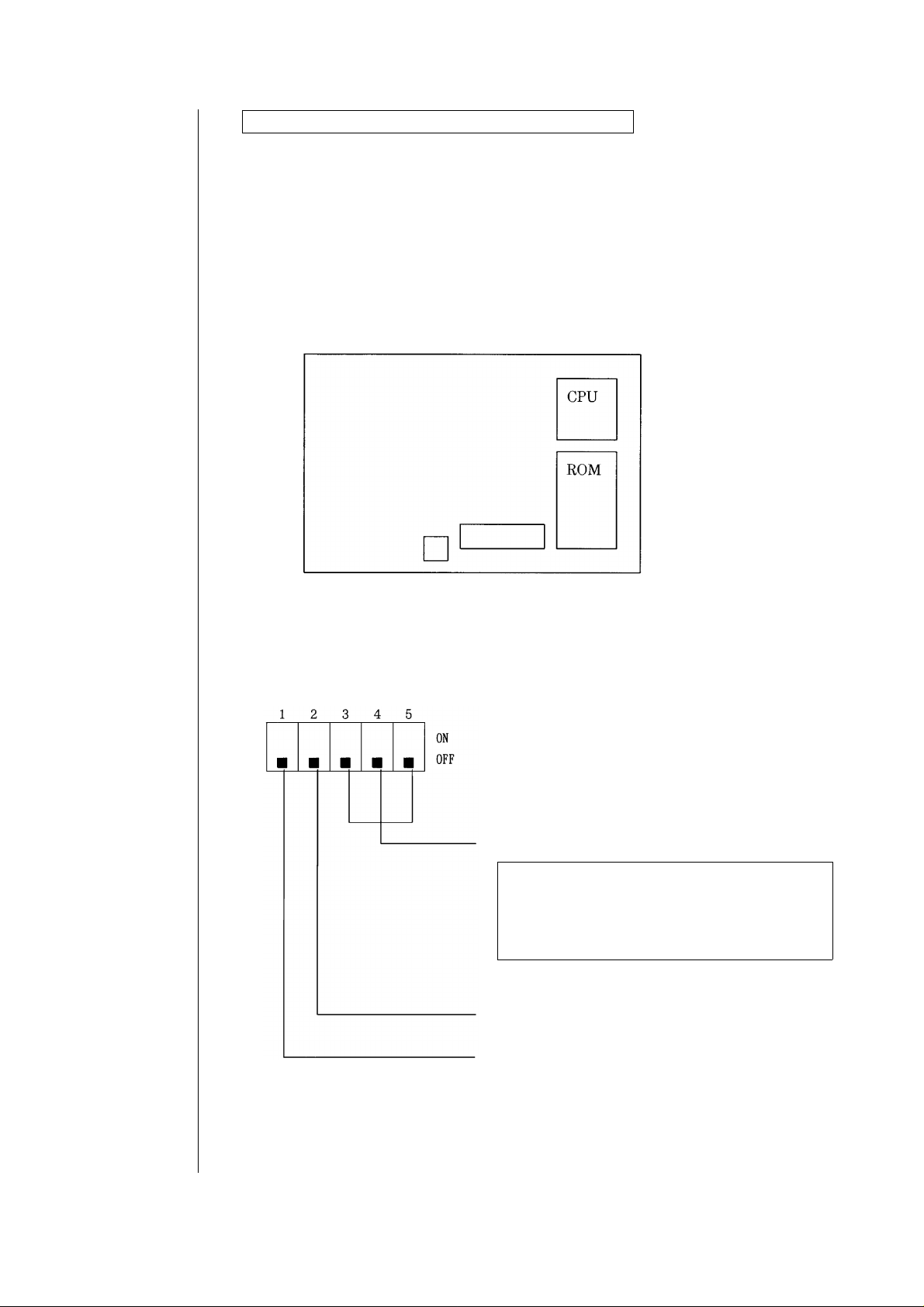
3.Description: 1. DIP switch position
The DIP switch is positioned on the control PWB as shown below.
DIP switch
Push switch
Fig. 1 DIP switch position
2. DIP switch setting
‘‘1" of the DIP switch is for setting AB series/Inch series, ’’2" for setting normal
paper/thin film, and ‘‘3-5" for setting the test mode.
For setting the test mode
When the power is supplied with the push switch
pressed, the machine enters the test mode.
Switching of the test mode is
made by opening/closing the DF after setting the
DIP switch.
For setting normal paper/thin film.
(OFF for normal paper, ON for thin film)
2/9
For setting AB series/Inch series.
(OFF for AB series, ON for Inch series)
Page 3
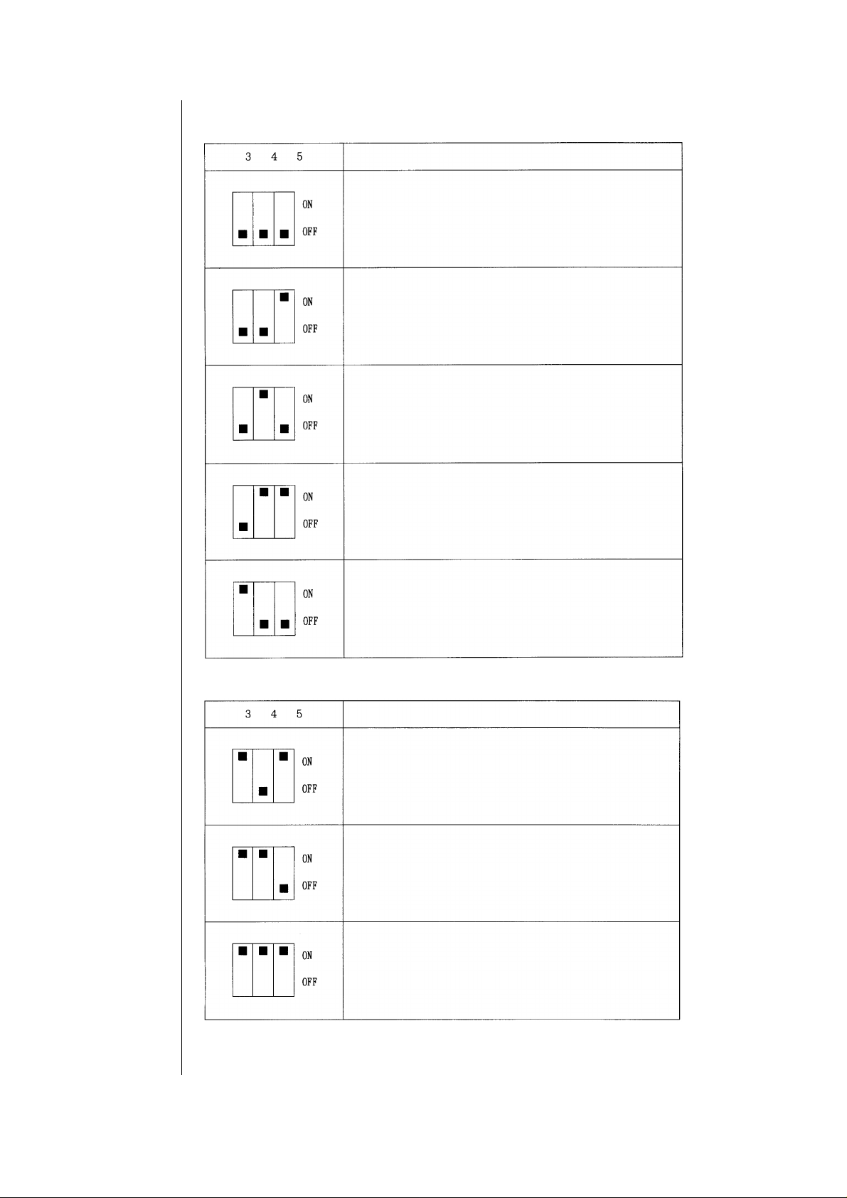
3. Test mode setting (For datails, refer to 5 the test mode specifications.)
Test mode kind
Paper pass mode.
Paper empty aging mode.
No colliding paper pass mode.
No DF cover paper pass mode.
Load check mode.
Test mode kind
2
E PROM initializing mode.
Sensor adjustment mode.
Sensor A/D change check mode.
3/9
Page 4

4. Shipment setting
When shipping the original feed unit, set the DIP switch (all of 1 to 5) to OFF.
Set to OFF
5. Test mode
Before turning the electrical power source ON, the push switch on the control
PWB should be depressed. Turning the electrical power ON while the switch
is being depressed will set the control PWB to TEST MODE. Furthermore,
the position of DIP switch no. 1 when the electrical power is turned ON for the
TEST MODE will determine the settings for the transport speed.
The TEST MODE settings will be carried out by DIP switches nos. 3 to 5. Finally,
the TEST MODE changeover will be carried out by opening and closing the DF
after the DIP switch settings have been carried out.
Transport Speed Settings
When the electrical power is turned ON for the TEST MODE
DIP Switch no. 1 ∼ OFF: The transport speed is 590 mm/s
DIP Switch no. 1 ∼ ON: The transport speed is 400 mm/s
TEST MODE Kinds
<1> Paper pass mode.
<2> Paper empty aging mode.
<3> No colliding paper pass mode.
<4> No DF cover paper pass mode.
<5> Load check mode.
2
<6> E PROM initializing mode.
<7> Sensor adjustment mode.
<8> Sensor A/D change check mode.
If a sensor adjustment error occurs when the power supply is turned ON for
the TEST MODE, the cause of the error will be displayed by the original
document feed LED (green) and the forgotten original document LED (red).
Type of Error Forgotten Original Document LED (Red) Original Document Feed LED (Green)
Register sensor adjustment error Extinguished Flashing
Register width sensor adjustment error Flashing Flashing
Paper delivery sensor adjustment error Flashing Extinguished
4/9
Page 5

Explanation of each mode
<1>Paper pass mode.
By setting DIP switches nos. 3 to 5 as indicated in the figure below and then
opening and closing the DF, the paper pass mode will be set.
By setting the original document in the upper tray the original document feed
LED (green) will illuminate. If the push switch is depressed, all of the pages of
the original document in the upper tray will be passed. During this operation,
the changing of the AB series/Inch series mode with DIP switch no. 1 and the
normal paper/thin paper mode with DIP switch no. 2 can also be carried out.
DIP Switch no. 1 ~ OFF: AB series ON: lnch series
DIP Switch no. 2 ~ OFF: Normal paper ON: Thin paper
Note: This mode can also function as the measurement mode, and by using the
measurement program RDP, the measurement of the over run pulse,
the size detection pulse, and the elapsed time of each type of jam time can
be carried out.
When a jam and error occurs, the cause of the error will be displayed by the original
document feed LED (green) and the forgotten original document LED (red).
Type of Error Forgotten Original Document LED (Red) Original Document Feed LED (Green)
Register sensor incomplete JAM Extinguished Illuminated
Register sensor remain JAM Extinguished Flashing
Paper delivery sensor incomplete JAM Illuminated Extinguished
Paper delivery sensor remain JAM Flashing Extinguished
Paper feed motor lock detect Illuminated Flashing
Paper transport motor lock detect Flashing Illuminated
Sensor trouble Flashing Flashing
5/9
Page 6

<2>Paper empty aging mode.
By setting DIP switches nos. 3 to 5 as indicated in the figure below and then
opening and closing the DF, the paper empty aging mode will be set.
The AB series/Inch series mode and the normal paper/thin paper mode changes
can be carried out in the same manner as in the paper pass mode, described in
above.
By depressing the push switch the paper empty aging mode will be set.
The operation which is appropriate for the original document size will be carried
out in accordance with the tray size.
Operations will be halted by opening and closing the DF.
<3>No colliding paper pass mode.
By setting DIP switches nos. 3 to 5 as indicated in the figure below and then
opening and closing the DF, the no colliding paper pass mode will be set.
6/9
This mode prevents the original documents from colliding by housing an original
document control plate when the original documents collide after the switch
back in the paper pass mode described in above. In all other respects, this mode
is the same as the paper pass mode described in above.
<4>No DF cover paper pass mode.
By setting DIP switches nos. 3 to 5 as indicated in the figure below and then
opening and closing the DF, the no DF cover paper pass mode will be set.
This mode is used to pass copy paper when there is no DF cover. A simulation of the
paper delivery sensor of the paper pass mode described in above is carried out. In all
other respects, this mode is the same as the paper pass mode described in above.
Page 7
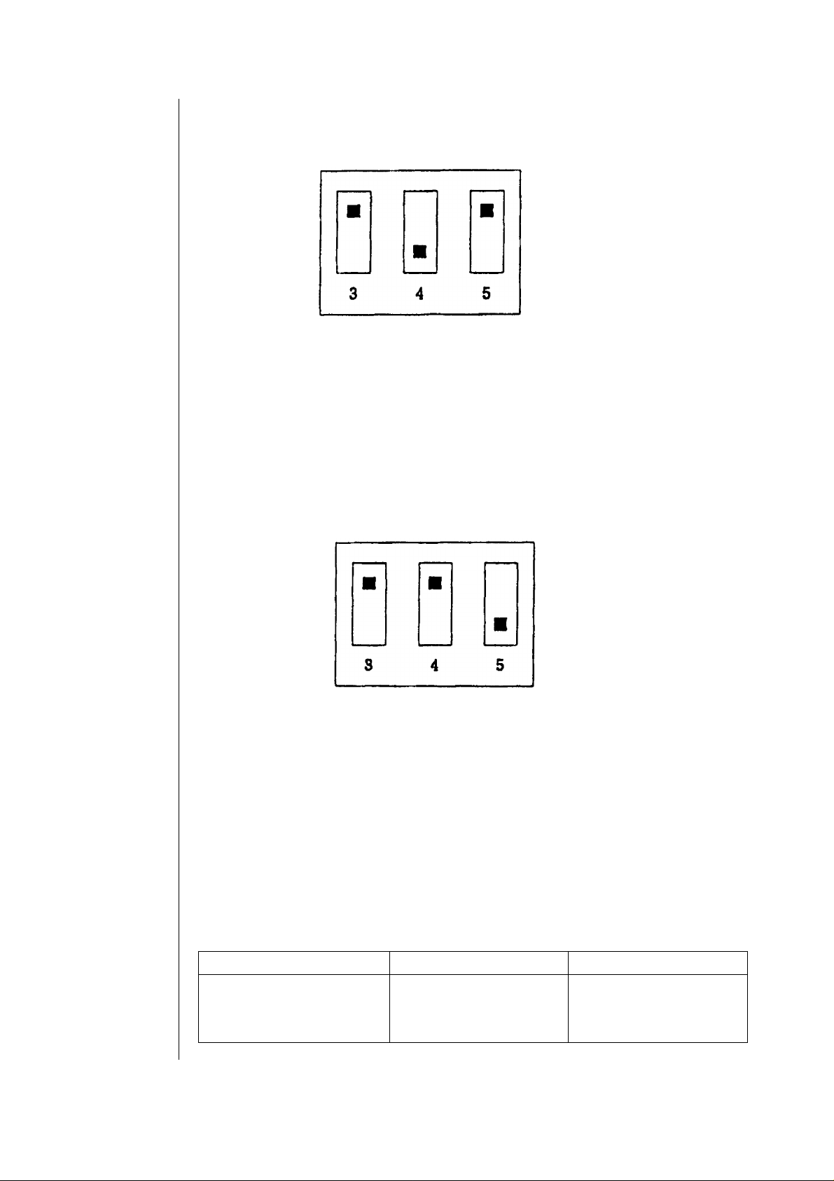
<5>Load check mode.
By setting DIP switches nos. 3 to 5 as indicated in the figure below and then
opening and closing the DF, the load check mode will be set.
The load in operation will change in the sequence described below when the
push switch is depressed.
1 Original document control plate: ON
2 Original document control plate: OFF
3 Paper feed motor: reverse rotation
4 Paper feed motor: halted
5 Paper feed motor: normal rotation
6 Paper feed motor: halted
7 Transport motor: reverse rotation (590 mm/s or 400 mm/s)
8 Transport motor: halted
9 Transport motor: normal rotation (590 mm/s or 400 mm/s)
10 Transport motor: halted
11 Transport motor: normal rotation (200 mm/s)
12 Transport motor: halted
13 Transport motor: normal rotation (full speed)
14 Transport motor: halted
15 Original document feed LED: ON
16 Original document feed LED: OFF
17 Forgotten original document LED: ON
18 Forgotten original document LED: OFF
7/9
Page 8
2
<6>E PROM initializing mode.
By setting DIP switches nos. 3 to 5 as indicated in the figure below and then
opening and closing the DF, the E PROM initializing mode will be set.
2
By depressing the push switch, the E PROM initializing mode will commence.
After the E PROM initializing process has been completed, the original
2
2
document feed LED (green) and the forgotten original document LED (red)
will illuminate at the same time, displaying that the E PROM initializing
2
process has been completed.
<7>Sensor adjustment mode.
By setting DIP switches nos. 3 to 5 as indicated in the figure below and then
opening and closing the DF, the sensor adjustment mode will be set.
By depressing the push switch, the sensor adjustment mode will commence.
Adjustment operations are carried out on the register sensor, the register
width sensor, and the paper delivery sensor.
8/9
When the sensor adjustment operations have been completed, the original
document feed LED (green) and the forgotten original document LED (red)
will illuminate at the same time, displaying that the sensor adjustment
operations have been completed.
When a sensor adjustment error occurs, the cause of the error will be displayed by the
original document feed LED (green) and the forgotten original document LED (red).
Type of Error Forgotten Original Document LED (Red) Original Document Feed LED (Green)
Register sensor adjustment error Extinguished Flashing
Register width sensor adjustment error Flashing Flashing
Paper delivery sensor adjustment error Flashing Extinguished
Page 9

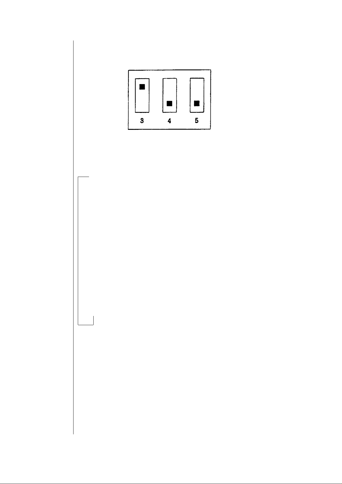
<8>Sensor A/D change check mode.
By setting DIP switches nos. 3 to 5 as indicated in the figure below and then
opening and closing the DF, the sensor D/A change check mode will be set.
This mode checks to see how the changes in the A/D values of each of the
register sensor, register width sensor, and paper delivery sensor take place
as the D/A output values are changed from 0 to 255 (0 V to 5 V).
The measurement program RDP 300 is used in this mode.
By depressing the push switch, the sensor change check mode will commence.
Checking operations are carried out on each of the register sensor, register
width sensor, and paper delivery sensor, and the D/A output values of each
sensor, and the A/D input value at that specific time is transmitted.
When the sensor A/D change check operations have been completed,
the original document feed LED (green) and the forgotten original document
LED (red) will illuminate at the same time, displaying that the sensor A/D
change check operations have been completed.
9/9
 Loading...