

Page 1
Date: Apr. 8, 1997
COPIER(OPTION) : SF-A54/S55
1. ESTABLISHMENT OF ADF AND RADF ORIGINAL COPY TRAY SCALES AS
SERVICE PARTS.
2. CORRECTION OF PWB PARTS CODES.
3. SEQUENCE OF OPERATIONS TO BE CARRIED OUT DURING THE OPTION TEST
MODE.
No. : SP-2098
1. Establishment of ADF and RADF original copy tray scales as service parts.
1.Model Name: SF-A15/A55/2050
2.General: The original document tray scale of the models listed above had not been established
as service parts, and therefore they have now been registered as service parts.
2. Correction of PWB parts codes.
1.Model Name: SF-S55
2.General: The part code of the IC (Q46) used in the main control PWB was doubled (two part
codes were listed for the same part). To correct this error one of the part codes has
been eliminated.
0GZWA45214000 ← This part code should be used when placing orders for the part.
0GZWA46214000 ← Eliminated
3. Sequence of operations to be carried out during the option test mode.
1.Model Name: SF-1020/2020/1120/ 2120
SF-A57/A18/S54
2.General: An error was discovered in the content of the service manual, and when carrying out
the option operations test mode in accordance with the mistaken content of the service
manual on machines which have had an option (SF-A18/A57/A54) installed for the
models listed above, the machines will not operate properly. To alleviate this problem,
the following sequence should be used.
SHARP CORPORATION Reprography Division
1/3
Green
C
Page 2
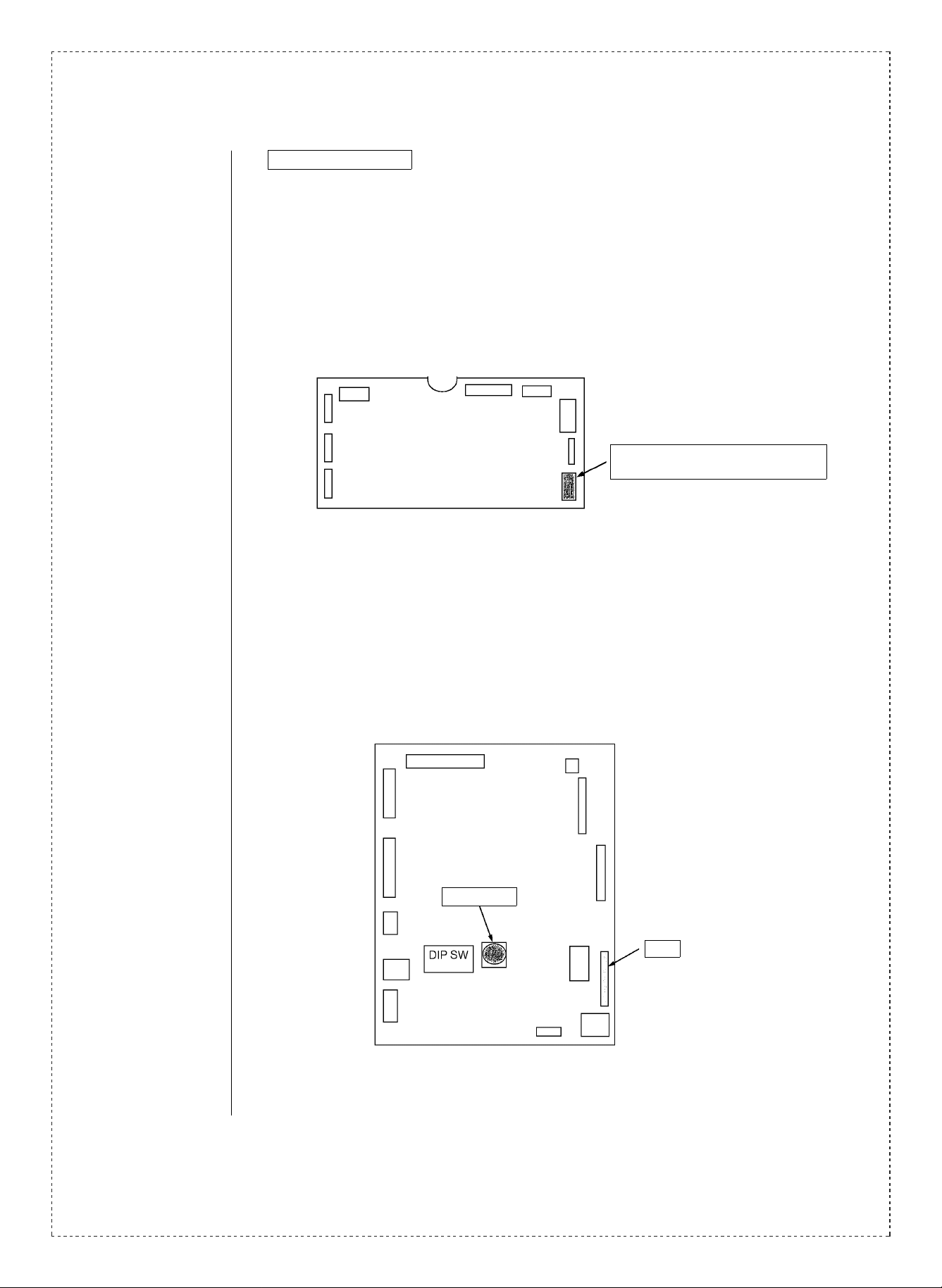
Test Mode Sequence
<SF-A18/A57>
(1) After checking to confirm that the main power supply of the machine has been
turned OFF, remove the lower cover and the power supply PWB.
(2) Disconnect the connector of the ADF control PWB (please refer to the figure
shown below), and connect the short connector.
(3) Reattach the power supply PWB and the lower cover.
(4) Remove the maintenance cover, and turn the main power supply of the
machine to ON while depressing the push switch on the control PWB.
(5) Set the dip switches to the appropriate testing mode setting. Each testing
mode will be set by the opening and closing of the DF. (Please refer to P.23-[8]-3
of the service manual)
CN8 should be used with model A18
CN9 should be used with model A57
<SF-S54>
(1) After checking to confirm that the main power supply of the machine has been
turned OFF, remove the R cover.
(2) Disconnect the connector (CN1) on the main PWB, and connect the short
connector.
(3) The option test mode will be set by turning ON the main power supply while
depressing the push switch on the main PWB.
(4) Set the dip switches to the appropriate testing mode. Each testing mode will be
changed by toggling the sorter joint switch ON and OFF.
(5) After carrying out each of the testing modes, the machine can be started up by
setting the push switch to ON.
(Please refer to p. 24-[6] of the service manual)
2/3
Push switch
CN1
Short connector: 0CW4074K526//
Page 3

Ref.
Model name Version P/G No.
No.
SF-A15
SF-A17
1
SF-A55
SF-A56
SF-2050 Inch series 0CW2198P361// AN
Inch series
AB series 0CW2199P383// AQ
Inch series 0CW2214P385// AN
Australia
SEEG
UK
∗ 0CW2214P480// AL
Inch series 0CW2198P361// AN
Australia
SEEG
UK
∗ 0CW2198P385// AQ
Inch series 0CW2214P385// AN
Australia
SEEG
UK
∗ 0CW2214P480// AL
Current parts New parts
Parts code Parts code
0CW2199P384// AN
0CW2214P360// BA
—
0CW2198P360// AR
0CW2214P360// BA
Price
rank
Parts name
Tray scales
Effec-
tive
time
—
Inter-
change-
ability
6
Note
2 SF-S55 All
SF-2020/2120
3
SF-1020/1120
SF-A57/A18/S54
<Interchange>
1. Interchangeable. 4. Not interchangeable.
2. C urr e nt t y pe c a n be u s ed i n place of n ew type.
New ty pe cann ot be us ed in place of curr ent type .
3. C urr e nt t y pe c a nn ot b e us e d in p l ace o f ne w ty p e.
New t y pe c a n be u sed in pl a c e of c u rr en t ty p e.
Parts marked with “ ” is important for maintaining the safety of the set. Be sure to replace these parts with
specified ones for maintaining the safety and performance of the set.
Overseas — — 0CW4074K526// AH Short connector 6
!
14 -75
0GZWA46214000 0GZWA45214000 IC 1
5. Interchangeable if replaced with same types of
relate d parts in use .
6. Others .
∗ The AB series except those models listed above.
3/3
 Loading...