

Page 1
Date: Nov. 15, 1996
COPIER (OPTION) : SF-A14/A15/A16
(Service Information)
No. : SP-2069
ESTABLISHMENT OF ADJUSTMENT TOO L S USED FOR
THE SEPARATOR SECTION AS SERVICE P ARTS.
1.Model Name: SF-A14/A15/A16
2.General: The adjustment tools used for the separator section have been established as service
parts.
Separator adjustment tool 0CW2199P431//
Please refer to the separator section adjustment procedures for details.
Separato r sectio n adj ustm ent pro cedur es
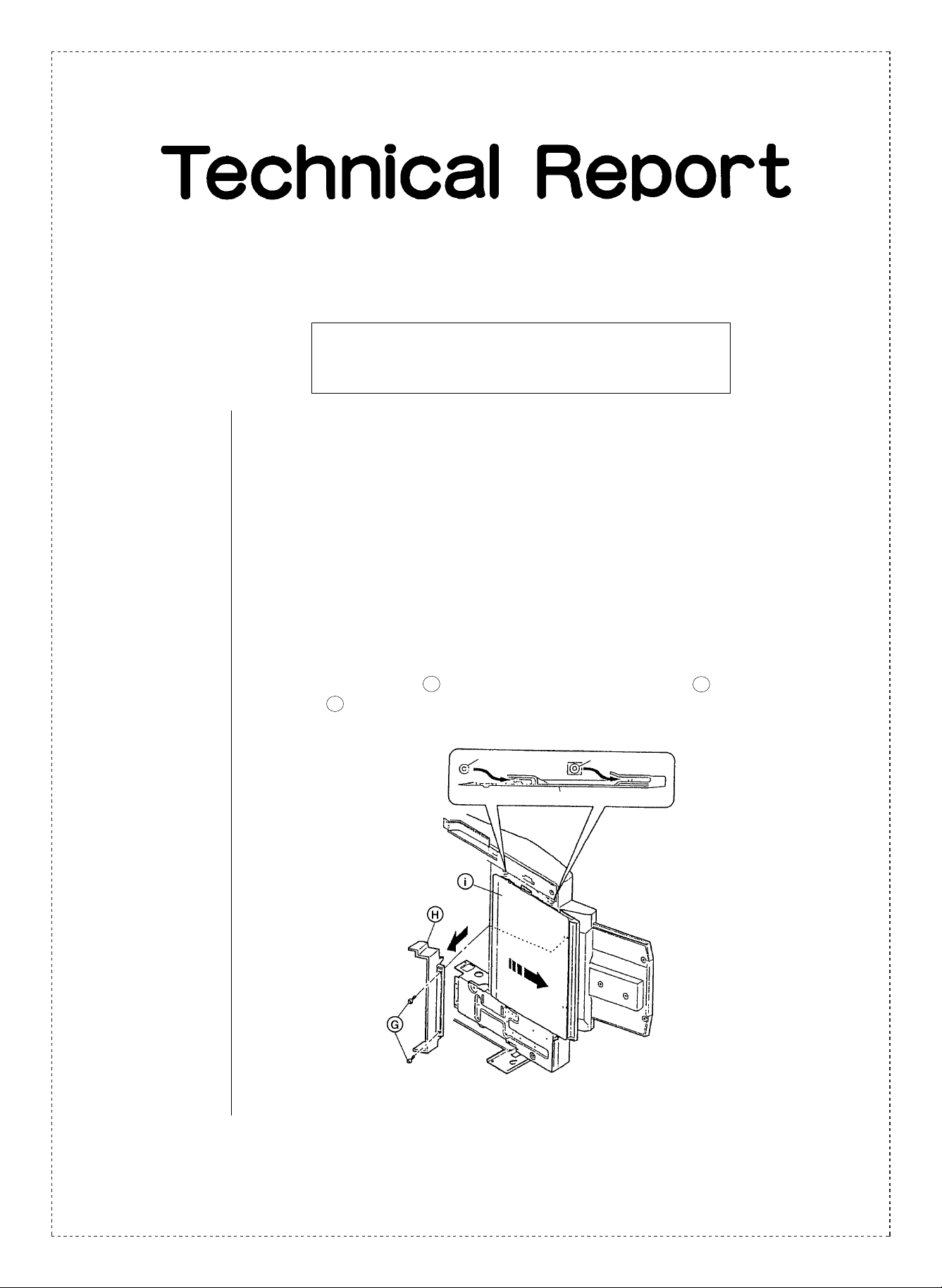
(1) Remove the screws G , and then remove the DP stopper guide H . Draw the DP
plate i in the direction of the arrows as illustrated in the figure shown below.
Boss
DP Plate
DP Plate
DP Stopper Guide
Boss
Screws
(Figure - 1)
SHARP CORPORATION Reprography Division
1/3
Green
C
Page 2
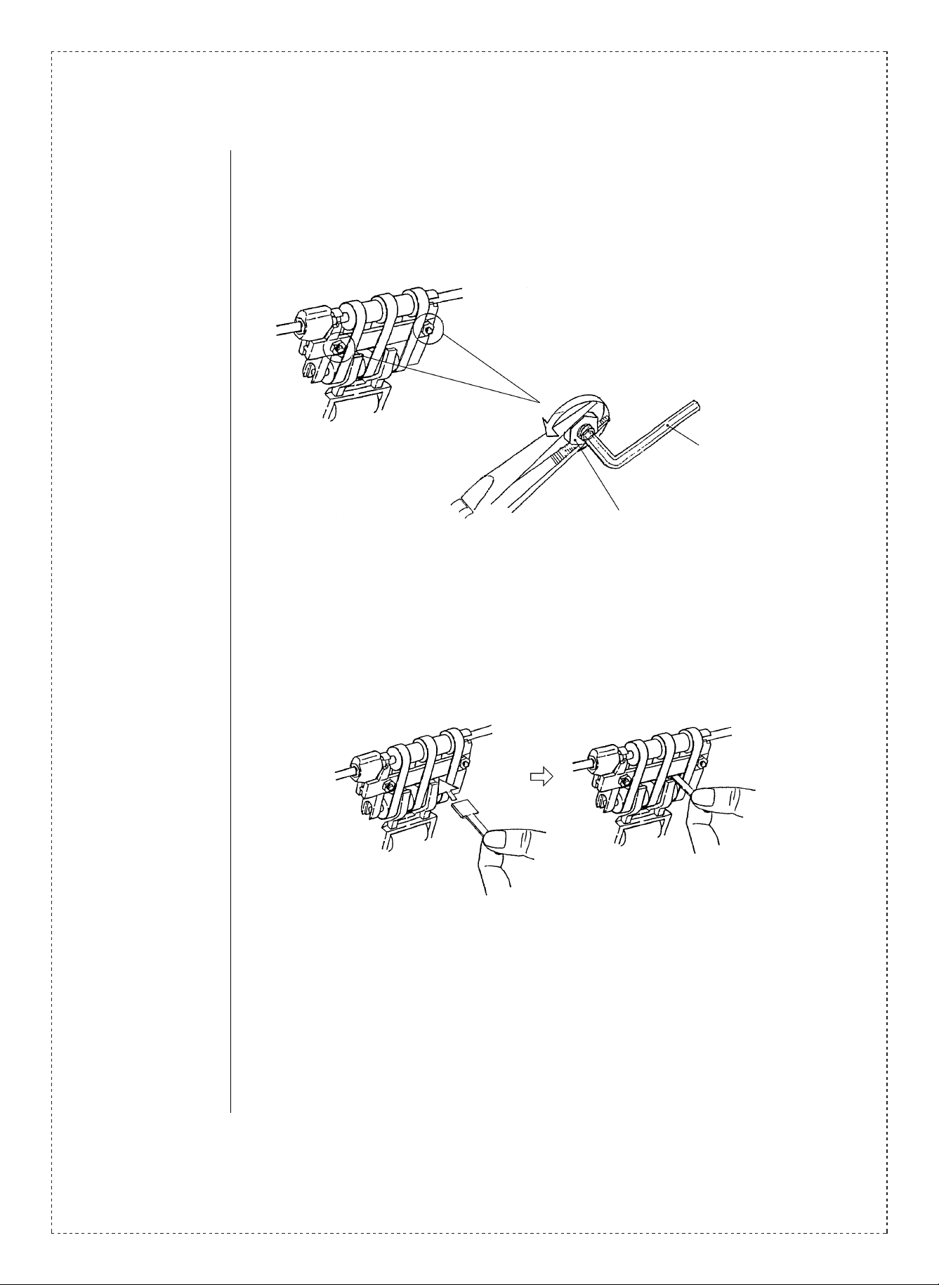
(2) Tighten the nut which secures the hexagon socket head cap screws (two locations in
both the front and the rear).
(Use a hexagonal wrench and turn the screw until it won’t turn any further, and then
loosen the nut.)
Hexagonal wrench (hold screw)
Nut
(Figure - 2)
(3) As illustrated in the figure shown below, the measuring tool should be inserted
through the space of the separator belt until it comes in contact with the D guide.
(Figure - 3)
2/3
Page 3

(4) Adjust the hexagon socket head cap screws (two locations in both the front and the
rear) so that the distance from the lower surface of the D guide to the upper surface of
the separator holder is the same height as the position ’h’ of the measuring tool.
(Adjustments should be carried out so that the height from the lower surface of the D
guide to the upper surface of the separator holder falls within a range of from 10.5 to
11.5 mm.)
The difference in height between the front and back sections of the separator holder
should be no greater than 0.5 mm.
Pick up roller
D guide
Nut
Separator holder ass’y
Shutter
Hexagon socket head cap screw
(Figure - 4)
(Measuring tool)
(5) After adjustments have been carried out, the nuts should be tightened (two locations
in both the front and the rear.)
(6) Attach the DP plate and DP stopper guide that were removed in (1) above.
Caution: When inserting the DP plate check to make sure that the four bosses are
securely in position.
The procedures described above comprise the adjustment procedures for the separator
section.
Ref.
Model
No.
SF-A14
SF-A15
SF-A16
<Inter chan g e>
1. Interchangeable. 4. Not interchangeable.
2. C urr e nt t y pe c a n be u s ed i n p la ce of new t y pe .
New ty pe cann ot be us ed i n place of curr ent type .
3. C urre nt ty pe cann ot be used i n place of new ty pe.
New t y pe c a n be u sed in p la c e of c u rr en t ty p e.
Parts marked with “ ” is important for maintaining the safety of the set. Be sure to replace these parts with
specified ones for maintaining the safety and performance of the set.
name
Version P/G No.
All — — 0CW2199P431// AD
!
Current parts New parts
Parts code Parts code
5. Interchangeable if replaced with same types of
relate d parts in use .
6. Others .
Price
rank
Parts name
Separator
adjustment tool
Effec-
Inter-
tive
change-
time
ability
—6
Note
3/3
 Loading...