

Page 1

Date: May. 31, 1996
COPIER : SF-2116
No. : SP-2012
NOTIFICA T ION OF CHANGES AND ADDI TI ONS OF PART S.
1.Model name: SF-2116/ 2118/1016/1018
2.General: Additions of parts have been made, and changes have been carried out on some of the
parts in the models listed above, and are hereby reported.
(1) Cases have occurred whereby the manual actuator attached to the lower portion of
the right cabinet was dropped, and a change in the shape of both end portions of the
actuator has been carried out as a measure to prevent this problem from reoccurring.
This change is effective from 1995 mid-October production.
(2) Changes have been carried out in the PID PWB used in the upper frame, and in the
DPPD circuit board of the paper feeding unit. Resistors had been installed on the back
side of the circuit boards in the in order to improve the performance of the paper
sensor, but these resistors have been changed for even more improvement. A change
in the parts codes of the circuit boards has also been carried out in accordance with this
action.
This change is effective from the start of 1996 February production.
SHARP CORPORATION Reprography Division
1/9
Green
C
Page 2
(3) The shape of the fusing roller in the lower frame unit has been changed from a
straight shape to an inverted crown shape to alleviate problems of wrinkling during
black beta and half-tone copy operations.
Note: When using the fusing roller after the change has been carried out it is necessary
to adjust the height of the paper guide in the fusing unit. Paper guide spacers and a
page of explanations have been added to the user’s kit (consumable items).
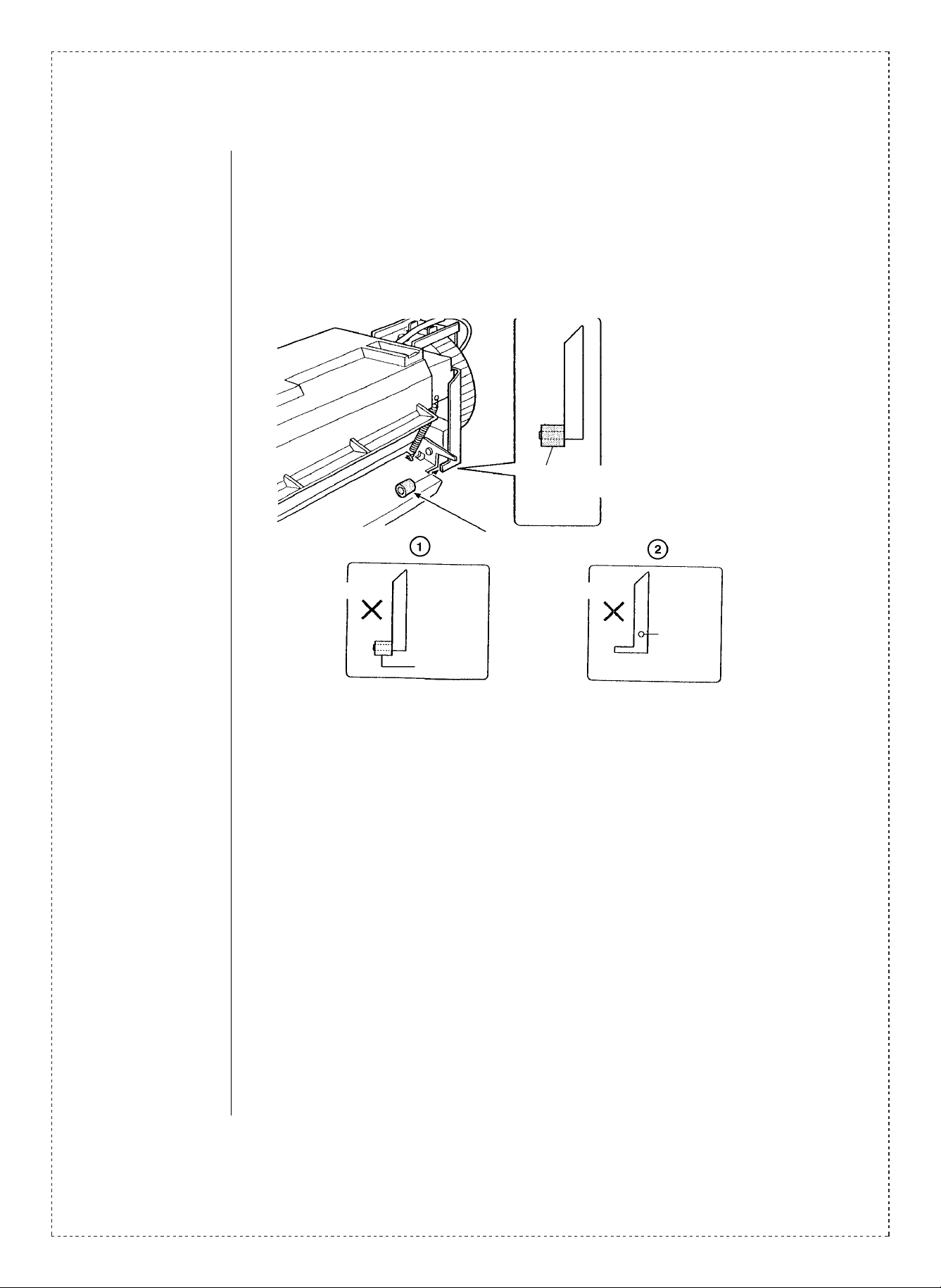
<When Using the Fusion Roller>
When using fusing roller N
(NROLR1058FCZZ) it is necessary to
attach spacers (PSPAG0691FCZZ) to
the P/G. Your cooperation concerning
this matter is requested.
Note: Action has already been carried
out in the fusing UN for ➀ and ➁
below, and the addition of spacers is
therefore not necessary.
➀ Units which have had a spacer
Spacer
(P/G Spacer T)
Spacer (P/G Spacer T)
PSPAG0691FCZZ
added to the edge bushing.
➁ Units which have had changes in
the shape of the metal plate carried
out in accordance with a change in
the metal molds.
Unnecessary
Edge
bushing
Unnecessary
Marking
∗ Japanese production
This change is effective from the start of 1995 August production.
French production (SMF)
This change is effective from 1995 mid-August production.
(4) Additions of parts have been made, and changes in some of the parts have been
carried out in order to alleviate the occurrence of F2 trouble and improve operations
efficiency .
Note: Changes have also been carried out in the printing content of the silk screening in
accordance with the changes described above.
∗ Japanese production
Running change will be effective from the start of 1995 December production.
Chinese production (SOCC)
This change is effective from the start of 1996 February production.
2/9
Page 3
(5) In order to improve production efficiency, the bias circuit of the high voltage unit has
been discontinued and the DC bias voltage has been changed to OV fixed.
∗ Japanese production
This change is effective from 1996 mid-January production.
Chinese production (SOCC)
Running change is effective.
French production (SMF)
Running change is effective.
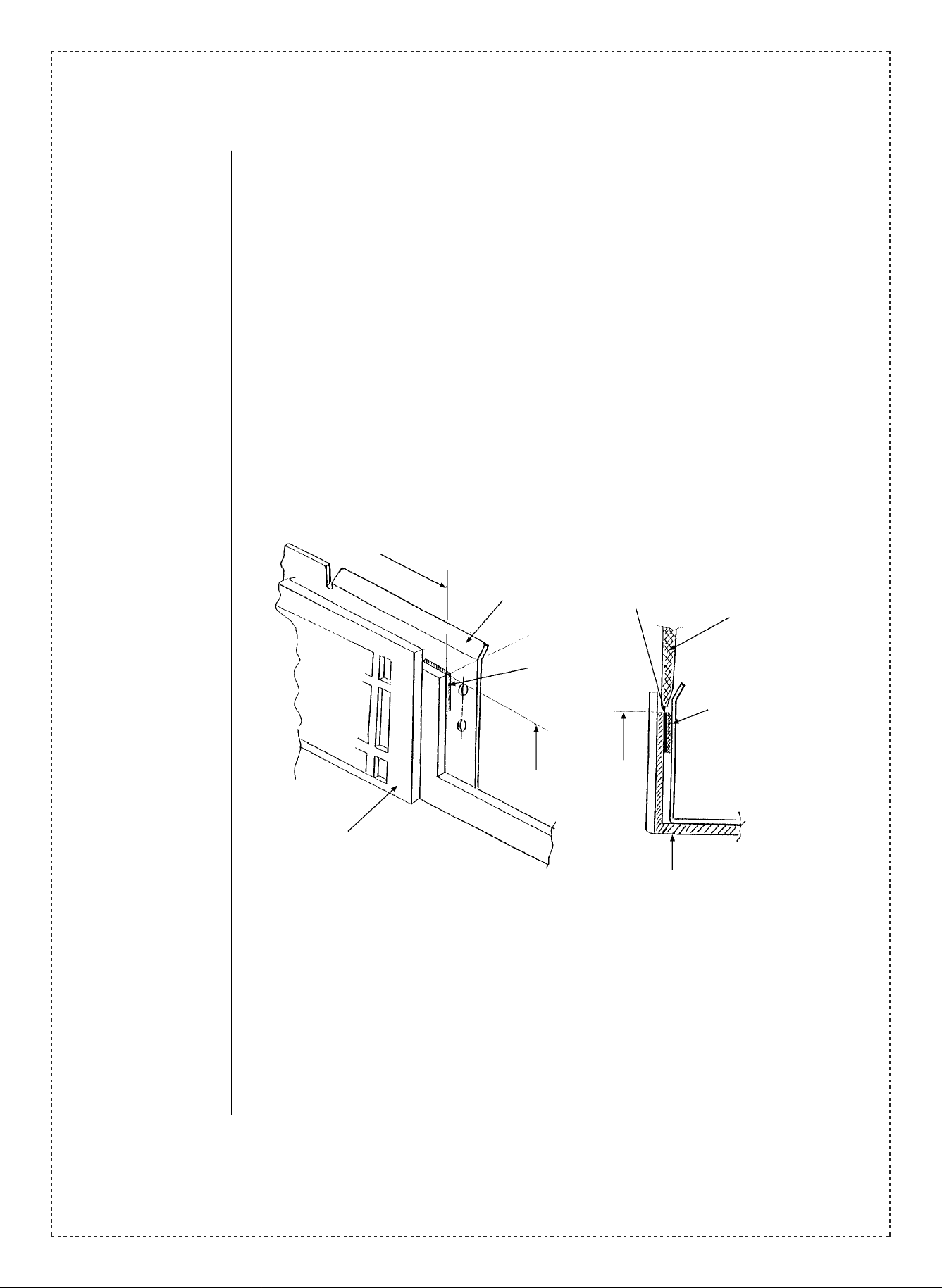
(6) Abnormal noise sometimes occurs due to the rear cabinet coming in contact with the
base plate when the upper frame is closed. T o alleviate this problem a spacer has been
attached between the lower frame and the base plate to maintain enough space for the
rear cabinet to enter.
(Central portion of the base plate of the rear frame)
Standard A
Base plate
Lower frame R
Base plate
frame spacer
Standard B
The side with
double-sided tape
Rear cabinet
when closed
Base plate frame spacer
Standard B
Base plate
3/9
Page 4

(7) Some scraping occurred between a portion of the cabinets during the vibration test.
To alleviate this problem the measures described below were carried out.
Attached to the hook section in two (2) locations.
Upper cabinet left
Front side of the machine
(Upper cabinet right)
(Hook tape)
(Hook protection)
Protect sheet
b
a
b
a
B
A
B
(Longdimensions)
A
B
11mm
A
2mm
(Short dimesions of the bend section)
B
A
P
Protect sheet
Base plate
4/9
Filament tape
19 x 750 m/m
It is necessary to bend the end portion over.
The action described above has been carried out as an improvement measure for
during shipping operations. No action is necessary after the machine has been installed.
∗ Japanese production
This change is effective from 1996 mid-January production.
Chinese production (SOCC)
This change is effective from the start of mass production.
French production (SMF)
This change is effective from 1996 mid-January production.
Page 5

(8) To carry out adjustments on the height of the fusing paper guide, action such as the
addition of height adjustment springs and spacers to the height blocks had been carried out.
Because proper height settings could not be easily established, and because problems
of large deviations in the height occurred, an adjustment plate has been added to
enable successive and simple height adjustments.
The installation procedures for the P/G height adjustment plate are described below.
Please refer to the operations procedures when carrying out the action described above.
1. Action for side F
a. Press the bent portion (standard A) of the adjustment plate to the metal plate section
of the fusing upper frame.
Note: It is essential to make sure that the metal plate is in proper contact with the frame
because the height and direction positions of block F are determined in accordance
with the contact with the frame.
b. The positioning protrusion of elevation block F should be aligned with the holes in
the adjustment plate (standard B) and secured with the upper frame by M3 x 8 screws.
2. Action for side R
a. Secure elevation block R to the top side with M3 x 8 screws. The block should be
secured to the amount of looseness.
3. Adjustment procedures.
a. By loosening the nut and rotating the stopper screw, the length of the extended
portion of the screw can be changed to adjust the height.
b. The height of the P/G is adjusted in accordance with the passing and stopping of the
adjustment tool.
c. Aft er adjustment procedures have been completed, tighten the nut, and take up any
slack with the upper and lower locking screws (2 locations).
Fusing front P/G
Fusing upper frame
Elevation block F
Permanent measure (after 3 months)
P/G Elevation Elevation standard related parts
2.2 Elevation adjustment plate
Clearance gauge
2.1-pass
2.4-stop
(NEW)
P/G elevation adjustment plate
LPLTH5156FCZZ
M3 x 8
XEPSD30P0800
M3 Nut (NEW)
XNGSD30-18000
Drive coupling stopper screw (NEW)
LX-BZ0670FCZZ
Notes
5/9
Page 6

Secured
upper side.
R Side
Standard A
Caution
Press into
contact
Screw lock
Elevation block R
F Side
Standard A
Standard B
Align with fixing
position.
Machines which have undergone the action described above do not require the addition
of the paper guide spacer described in (3) above.
∗ Japanese production
This change is effective from the start of 1996 February production.
Chinese production (SOCC)
This change is effective from the start of mass production.
French production (SMF)
This change is effective from the start of 1996 March production.
6/9
Page 7

(9) A change has been carried out in the shape of some of the parts in the lower paper
feeding unit in order to improve servicing efficiency and reliability. (This change has
been carried out only on models SF-2118/1018.)
Old New
W base paper feeding frame R LFRM-0866FCZZ LFRM-0866FCZ1
W base paper feeding frame F LFRM-0865FCZZ LFRM-0865FCZ1
W base paper feeding bearing NSFTZ 2182FCZZ NSFTZ 2182FCZ1
W base paper feeding guide sheet (added) PSHEZ4044FCZZ
In accordance with the changes described above, the additions and eliminations of
parts described below have also been carried out. (Please refer to the table below. )
: Necessary
: Unnecessary
how to recognize differences
There is a change in the shape
of the bushing of the double
plate paper feeder roller.
Z1 parts are marked with an "A"
>ABS<
Z1ZZ
A soace is opened
A
Upper double
plate paper
feeding frame
Lower double
plate paper
feeding frame
Double plate
paper feeder
roller bearing
LX-WZ0017FCZZ
washer t0.5 Qty 1
LX-WZ0011FCZZ
washer t0.8 Qty 1
PSHEZ4044FCZZ
Double plate paper feeder guide sheet Qty 1
LX-WZ0144FCZZ
Fusing washer
∗ Attach to the back side of the upper W base
paper feeder frame
LX-WZ0017FCZZ
washer t0.5 Qty 1
Qty
5
This change is effective from the start of 1995 November production.
7/9
Page 8

8/9
Ref.
No.
1
2
3
4
5
6
7
Model
name
SF-2116
SF-2118
SF-1016
SF-1018
SF-2116
SF-2118
SF-1016
SF-1018
SF-2116
SF-2118
SF-1016
SF-1018
SF-2116
SF-2118
SF-1016
SF-1018
SF-2116
SF-2118
SF-1016
SF-1018
SF-2116
SF-2118
SF-1016
SF-1018
SF-2116
SF-2118
SF-1016
SF-1018
SF-2116
SF-2118
SF-1016
SF-1018
SF-2116
SF-2118
SF-1016
SF-1018
SF-2116
SF-2118
SF-1016
SF-1018
SF-2116
SF-2118
SF-1016
SF-1018
SF-2116
SF-2118
SF-1016
SF-1018
SF-2116
SF-2118
SF-1016
SF-1018
Version P/G No.
5 -10
10 -48 CPWBF1089FC31 CPWBF1089FC32 AR PID PWB
17 -7
23 -5
19 -25 NROLR1058FCZZ NROLR1058FCZZ BK Pressure roller
19 — PSPAG0691FCZZ AE
All
14
11 -45 RTRNZ0508FCZZ RTRNZ0508FCZ1 BS
19
1
Current parts New parts
Parts code Parts code
MLEVP0673FCZZ MLEVP0673FCZ1 AF
CPWBF1086FC31 CPWBF1086FC32 AP DPPD PWB
VRD-RB2HY202J VRS-RA3AA102J AB Resistor 4
VRNHT2EK1001F VRNHT2EK1501F
Price
Parts name
rank
Manual feed
actuator
Paper guide
spacer
Effec-
tive
time
Mid-
’95/10
1st lot
’96/2
Inter-
change-
ability
3
5
Note
R18
∗
VRNHT2EK5100F VRNHT2EK5100D
— VRNHT2EK1302D R48
VCEAGA1CW476M VCEAJU1CW476M AB Capacitor C1
PSPAZ0695FCZZ
—
LPLTM5164FCZZ
Transistor
AC
High voltage
transformer
Base plate
frame spacer
AC
Hook protection
plate
R19
∗ —
Page 9

Ref.
Model
No.
SF-2116
SF-2118
SF-1016
SF-1018
7
SF-2116
SF-2118
SF-1016
SF-1018
SF-2116
SF-2118
SF-1016
SF-1018
SF-2116
SF-2118
8
SF-1016
SF-1018
SF-2116
SF-2118
SF-1016
SF-1018
SF-2118
SF-1018
SF-2118
SF-1018
9
SF-2118
SF-1018
SF-2118
SF-1018
<Inter change>
1. Interchangeable. 4. Not interchangeable.
2. C urr e nt t y pe c a n be u s ed i n p la ce of new ty pe .
New ty pe cann ot be us ed i n place of curr ent type .
3. C urre nt ty pe cann ot be used i n place of new ty pe.
New t y pe c a n be u sed in p la ce of c u r ren t ty p e.
Parts marked with “ ” is important for maintaining the safety of the set. Be sure to replace these parts with
specified ones for maintaining the safety and performance of the set.
name
Version P/G No.
1
28 PSHEZ4137FCZZ AC
16
All
23 -15 LFRM-0866FCZZ LFRM-0866FCZ1 AN
23 -41 LFRM-0865FCZZ LFRM-0865FCZ1 AY
23 -33 NSFTZ2182FCZZ NSFTZ2182FCZ1 AQ
23 — PSHEZ4044FCZZ AC
!
Current parts New parts
Parts code Parts code
PTPE-0220FCZZ AB Hook tape
—
LPLTM5156FCZZ AE
LX-BZ0670FCZZ AC
XNGSD30-18000 AA Nut (M3)
5. Interchangeable if replaced with same types of
relate d parts in use .
6. Others.
Price
rank
Parts name
Cabinet protect
sheet
P/G elevation
adjustment plate
Drive coupling
stopper screw
W base paper
feeding frame R
W base paper
feeding frame F
W base paper
feeding bearing
W base paper
feeding guide
sheet
Effec-
tive
time
∗ —
1st lot
’95/11
Inter-
change-
ability
5
Note
9/9
 Loading...