

Page 1
Date: Nov. 15, 1995
DUPLICATOR/COPIER :SD-2050/SF-2050
[Service Information]
No. : SP-1970
SERV ICE MANUAL CORRECTIONS.
1.Model name: SD-2050/SF-2050.
2.General: Errors have been found in the service manual and circuit diagrams for the models listed
above, and are hereby reported.
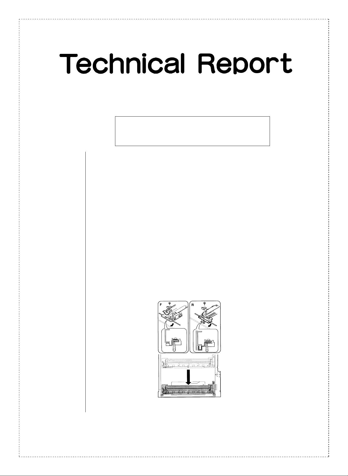
3.Description: 1. There was an error in the content concerning the installating position of the copy lamp
which is listed in Service Manual No. 1 on page 7-13. The error has been corrected as
shown below. (Note: The underlined section(s) are the section(s) that have been
corrected.)
Mirror base wire stretching
Refer to “[8] ADJUSTMENTS.”
Copy lamp unit installing position
➀ Pass the front/rear mirror base drive wire between the copy lamp unit frame and the
wire fixing plate.
At this time, do not tighten the wire fixing screw.
➁ Press the copy lamp unit onto the positioning plate, and tighten the wire fixing screw .
SHARP CORPORATION Reprography Division
1/7
Green
C
Page 2
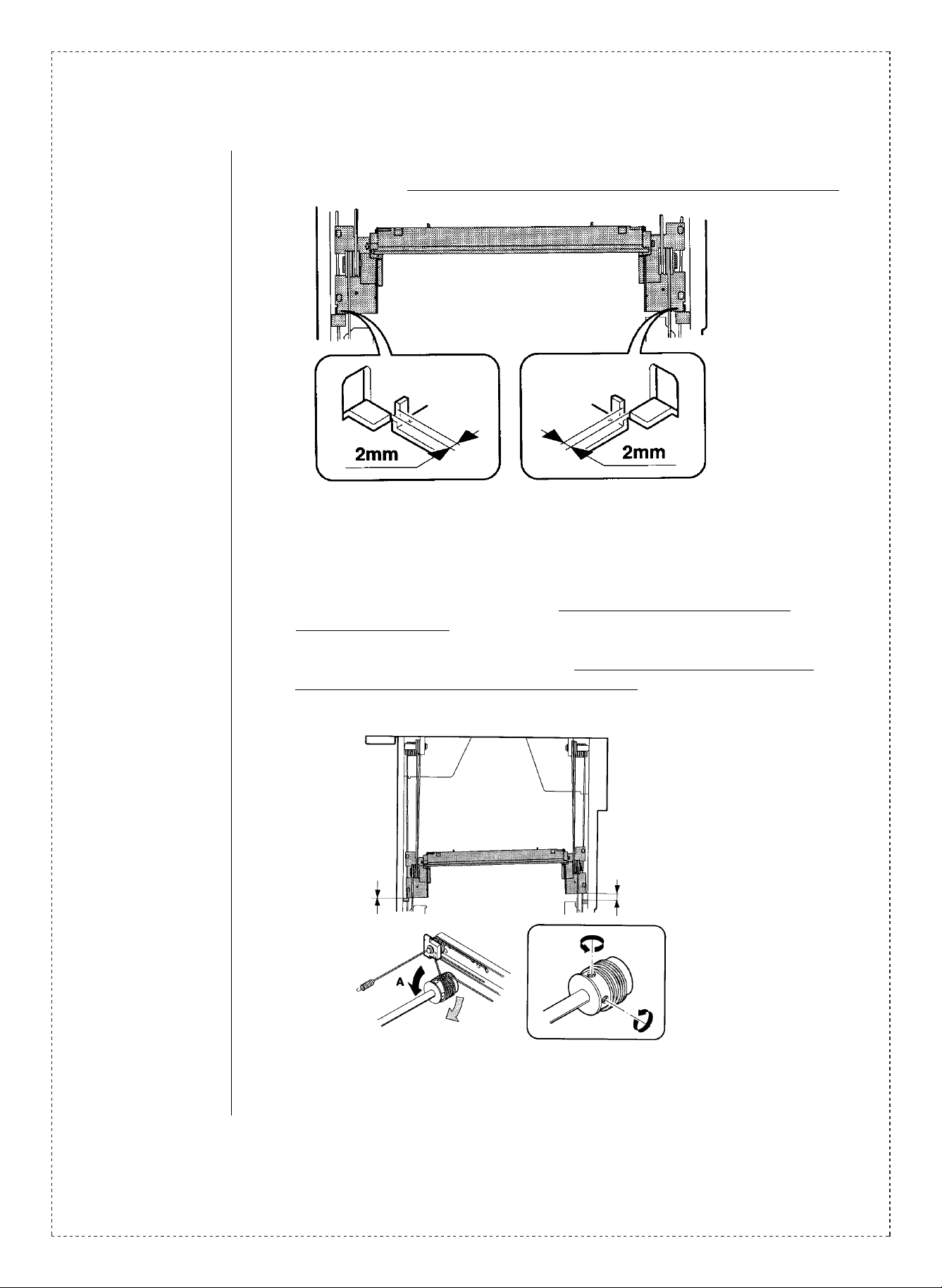
∗ Allow a clearance of 2 mm between the No. 2/3 mirror base unit and the optical
section projection when the copy lamp unit is pressed onto the optical section projection.
No.2/3 mirror base unit installing position
This is to adjust the parallelism of mirror base B and the drum surface and the original
surface.
➀ Manually turn the mirror base drive pulley, and press the copy lamp unit onto the
optical section projection. If the clearance between mirror base B and the rear frame is
2 mm in the front frame side and in the rear frame side, parallelism of mirror base B is
proper and no further adjustment is required. If not, loosen the pulley fixing screw as
shown below, and move the pulley to adjust parallelism.
2/7
Page 3
2. There was an error in the content concerning the entry, “(6) Inputting the scaling
interval move correction value”, which is listed in Service Manual No. 1 on page 8-11.
The error has been corrected as shown below. (Note: The underlined section(s) are the
section(s) that have been corrected.)
(6)Zoom shift correction value input
(Lens characteristics input)
Each lens has a variation in the focal distance, and the lens shift distance at zoom copy
must correspond to the lens focal distance.
If the lens shift distance at each zoom copy is fixed to a value regardless of the lens
focal distance, the coy magnification ratio will vary in proportion to the radiation in the
lens focal distance.
To prevent against the above trouble, the lens focal distance ranks (in the left table) are
stored in the memory by the simulation. When zoom copying, the lens shift distance is
calculated accordingly to the lens focal distance based on the data to obtain the proper
zoom ratio.
Comparison between the lens value and the
simulation input value
(When focusing or the
magnification ratio is not proper
in zoom copy)
1. When focusing or the
magnification ratio is not proper
in zoom copy, adjust as follows:
.
When focusing or the
magnification ratio of 50%
reduction is not proper, change
simulation 48-01B setting.
.
When the magnification ratio of
50% reduction is not proper,
change simulation 48-01E
setting.
2. When focusing or the
magnification ratio of 200%
enlargement is not proper:
.
When focusing is not proper,
change simulation 48-01C
setting.
.
When the magnification ratio is
not proper, change simulation
48-01F setting.
Lens display
value
O-L
-4.0 ~ -3.8 66 ~ 65 89 ~ 87
-3.8 ~ -3.4 65 ~ 63 87 ~ 83
-3.4 ~ -3.0 63 ~ 61 83 ~ 79
-3.0 ~ -2.6 61 ~ 59 79 ~ 75
-2.6 ~ -2.2 59 ~ 57 75 ~ 71
-2.2 ~ -1.8 57 ~ 55 71 ~ 67
-1.8 ~ -1.4 55 ~ 53 67 ~ 63
-1.4 ~ -1.0 53 ~ 51 63 ~ 59
-1.0 ~ -0.6 51 ~ 49 59 ~ 55
-0.6 ~ -0.2 49 ~ 47 55 ~ 51
-0.2 ~ +0.2 47 ~ 45 51 ~ 47
+0.2 ~ +0.6 45 ~ 43 47 ~ 43
+0.6 ~ +1.0 43 ~ 41 43 ~ 39
+1.0 ~ +1.4 41 ~ 39 39 ~ 35
+1.4 ~ +1.8 39 ~ 37 35 ~ 31
+1.8 ~ +2.2 37 ~ 35 31 ~ 27
+2.2 ~ +2.6 35 ~ 33 27 ~ 23
+2.6 ~ +3.0 33 ~ 31 23 ~ 19
+3.0 ~ +3.4 31 ~ 29 19 ~ 15
+3.4 ~ +3.8 29 ~ 27 15 ~ 11
+3.8 ~ +4.0 27 ~ 26 11 ~ 7
adjustment Sim. 48-01D
Cprrection reference value
No.4/5 mirror focus
Vertical magnification
ratio adjustment Sim.
48-01A
For Sim. 48-01B/C/E, use the P. No. attached to
the lens as the reference of the input value.
3/7
Page 4

3. There was an error in the content listed in Service Manual No. 1 on page 8-27. The
simulation number used for the position adjustments in the ADU unit, for the rear end
plate and the interface board was incorrect, and has been corrected as shown below.
(1) Position adjustment for the rear end plate:
simulation No. : SIM.52-01 (incorrect) → SIM.52-02 (corrected).
(2) Position adjustment for the interface board:
Simulation No. : SIM.52-02 (incorrect) → SIM.52-01 (corrected).
4. A change has been carried out in the content concerning the entry “9. Curl Correction
Unit Adjustments”, which is listed in Service Manual No. 1 on page 8-29. The curl
correction unit itself has been changed as of the first lot of production, and in
accordance with this change the adjustment procedures have also been changed, and
the content on page 8-29 of Service Manual No. 2 has been changed as shown below .
➀ Remove the curl correction unit from the main body.
➁ Loosen the fixing screw of the roller support plate.
➂ Insert the nip quantity adjustment jig(UKOG-0237FCZZ)between the curl roller and
the reverse roller, slide the roller support plate to adjust so that the nip quantity
becomes as shown below.(Adjust both on the front and rear sides.)
AB series in Japan and The lead tip of 5.6(AB) of the
outside Japan: nip quantity adjustment jig.
Inch series outside Japan: The lead tip of 5.8(IN)of the nip
quantity adjustment jig.
Roller support plate
Jig insertion point
Nip quantity adjustment jig
Parts code:UKOG-0237FCZZ
Price rank:BA
Reverse roller
Curl roller
Jig insertion point
4/7
Page 5

➃ When a curl is generated to cause folding, wrinkles, and a jam, adjust as follows:
∗1. In the case of upward curl on the ADU tray, reduce the interval between the curl
roller and the reverse roller by 0.2mm.
∗2. In the case of downward curl on the ADU tray, increase the interval between the curl
roller and the reverse roller by 0.2mm.
Destination ∗1 Normal ∗2
AB series in Japan and outside
Japan
Inch series outside Japan 5.6 5.8 6.0
5. The explanation chart for the JAM data corresponding to each LCD display of the
JAM counter display in Simulation 22-02.
Display Explanation
LCC LCC Feed Jam.
CAS1 Tray 1 Feed Jam.
CAS2 Tray 2 Feed Jam.
CAS3 Tray 3 Feed Jam.
CAS4 Tray 4 Feed Jam.
BYPASS Manual Tray Feed Jam.
ADU ADU Feed Jam.
PFD1 PFD1 Residual Jam.
PFD2 PFD2 Residual Jam.
PFD3 PFD3 Residual Jam.
PFD4 PFD4 Residual Jam.
DPFD DPFD Residual Jam.
PPD1 PPD1 Residual Jam.
PPD2 PPD2 Residual Jam.
PPD3 PPD3 Residual Jam.
PSD PSD Residual Jam.
POD POD Residual Jam.
DPID1 DPID1 Residual Jam.
DPID2 DPID2 Residual Jam.
PFDL2 PFDL2 Residual Jam.
DPPD1 DPPD1 Residual Jam.
DPPD2 DPPD2 Residual Jam.
DPPD3 DPPD3 Residual Jam.
SPID Sorter Paper Entry Jam.
SPOD Sorter Paper Discharge Jam.
OG_FD RADF Reserve Coppy Paper Jam.
OG_ST RADF Supply Jam.
EXT RADF Discharge Jam.
REV RADF Reverse Roller Jam.
5.4 5.6 5.8
5/7
Page 6

6. A part of the circuit diagram for the operations control PWB was not included in the
collection of circuit diagrams, and has been added.
6/7
Page 7

7/7
 Loading...