

Page 1
Date: Jul. 31, 1995
COPIER : SF-2116
No. : SP-1916
1.PRECAUTIONS TO BE TAKEN DURING
MAINTENANCE TO THE OPTICAL UNIT
2.REGARDING PROBLEMS WITH THE L4-01
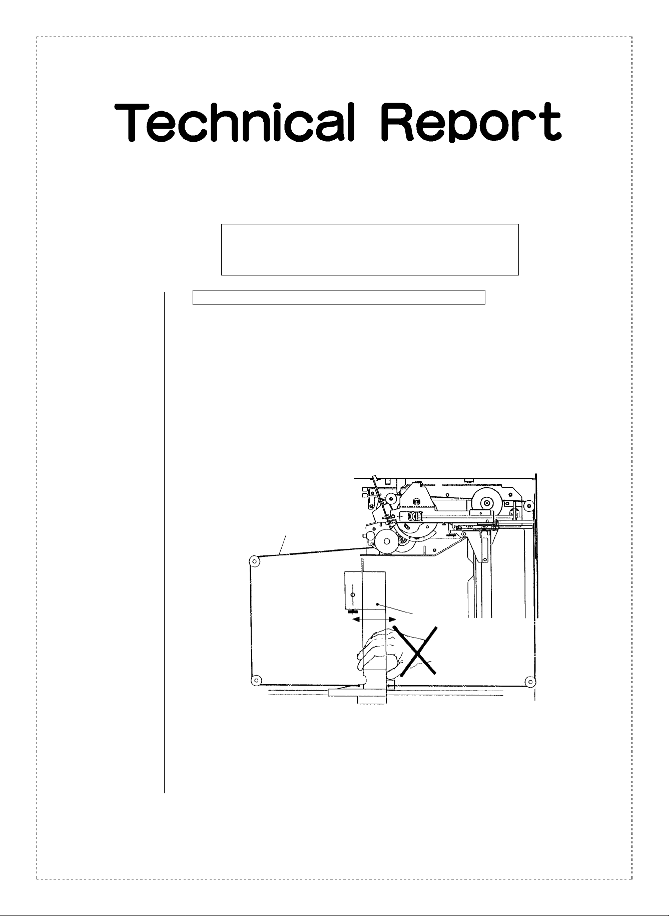
1.Precautions to be taken during maintenance to the optical unit.
1.Model Name: SF-2116/ 21 18/1016/1018
2.General: In order to help prevent problems during market use, please take note of the following.
3.Description: Do not handle the zoom mechanism for models with only one cam and one motor in the
same way as has been done for past models (SF-2022/2027, which have two motors).
If you move the lens of the one motor models by hand, (as was the procedure for the
two motor models), the lens drive wire is likely to get caught in the lens carriage. (see
Fig. 1).
Fig. 1
Lens drive wire
Lens carriage
SHARP CORPORATION Reprography Division
1/4
Green
C
Page 2
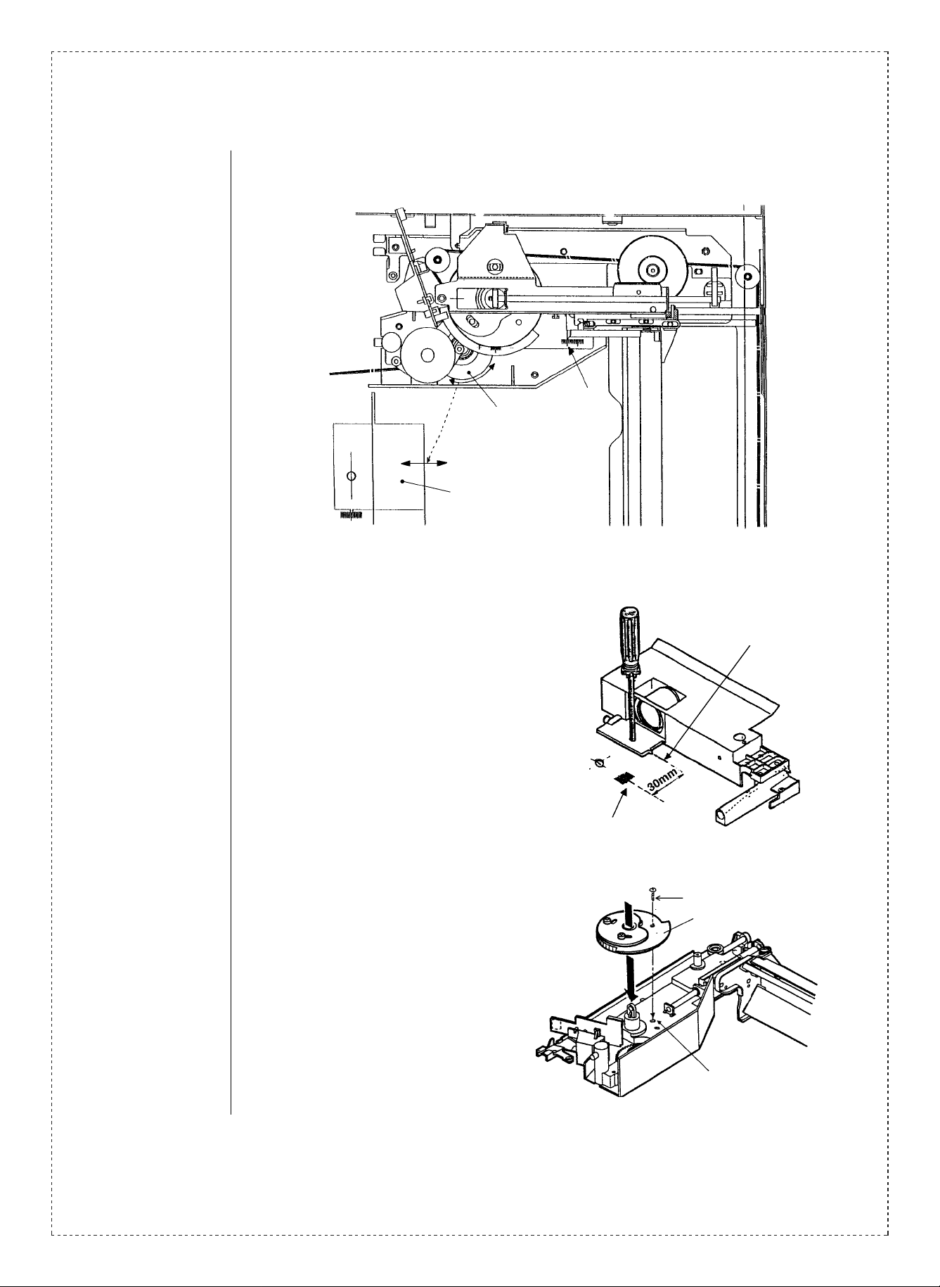
If you must move the lens by hand, do it by rotating the step gear which is connected to
the mirror motor. (See Fig. 2)
Fig. 2
4/5 Mirror UN
Step gear
(rotating this gear moves
the lens)
Lens
Base sticker
If the lens wire has come off of the teeth of its guide, please carry out the following
procedure.
(1) Remove the lens wire (see the Service Manual)
(2) When reattaching the wire, place a pin
or screwdriver (as a temporary fixing
measure) in the opening which you will
find slightly closer to the other end than
the home position and then proceed to
attach the wire. (See Fig. 3)
The original home position
Fig. 3 - the lens carriage in its temporarily fixed position
(3) While the pin or screwdriver of (2) is still
attached, use φ4 pins or M4 screws to fix
the openings in the scaling cam drive
gear to the openings in the zoom base
temporarily. Then attach the scaling
drive gear. (See Fig. 4)
There is a sticker here
φ4 pins (or longer M4 screws) used
as a temporary f i xing measure
The scaling cam drive gear
2/4
Fig. 4 - Attaching the scaling cam drive gear
Note: this opening
Page 3

(4) Take out the pin or
screwdriver which was being
used to fix the position of the
lens carriage temporarily.
Then rotate the scaling cam
drive gear clockwise by hand.
This will increase magnification. When the parts are at
their home position, the
sensor on the scaling cam
drive gear will be lined up
with the MHP sensor.
(When the parts are in this
position, Sim. 48-1A shows
a base value of 50).
(See Fig. 5)
(5) After turning the power off
temporarily, follow the
instructions in the service
manual to attach and adjust the
“koro” holder and the 4/5 mirror
unit.
Fig. 5 - The position of the sensor of the scaling cam
drive gear when it is in home position
This rotation angle
is equivalent to 50
steps/counts of
the lens motor.
Lens drive motor
Optical PWB
The scaling cam drive gear
MHP sensor (in the PWB)
2.Trouble with the L4-01.
1.Model Name: SF-2116/ 21 18/1016/1018
2.General: The margin in the setting for the power supply boundary is very narrow, and in some
machines the burden carried by the drivers may become very large. During multiple
copying, the power supply boundary may shift and cause L4 problems. Please follow
the procedure outlined below should this occur.
3.Description: The basic boundary will be changed from its current value of 3.0 A to a new value of 4.1
A.
3/4
Page 4

For models already out on the market, solder a 22KΩ resist or between the 3rd and 7th
pin of the IC20, which is located at the bottom right of the main PWB.
Main PWB
IC 20
IC 21
ICIO
Additional resistor (22KW) placed
between the 3rd and 7th pins
CN-D
Resistance 22kΩ
VRD-HT2EY223J
Available as service parts
There is also the possibility that L4 problems are occurring due to malfunctions in the
main motor/encoder (the font sensor). Please investigate this possibility as well.
The notes above are only in regards to models which are already on the market.
Information regarding altered production will be provided at another time.
4/4
 Loading...