

Page 1

COPIER : SF-2116
Date
:
Jul. 26, 1995
No. : SP-1912
AN ALTERATION TO THE SOFTWARE OF
SF-2116/2118
1.Model name: SF-2116/2118
2.General: A description of changes which should be made to correct the poor functioning of the
software.
3.Description: 1. The toner control sensor value received when performing Simulation 50-02, part D,
changes from it’s correct base value. (The value changes to 50 or 0, resulting in
‘‘overtoning’’)
2. When Simulation 50-02 is performed, the counter display shows only the last two
digits of the number entered, but after the Simulation is completed, if the number that
was entered is called up again, only the first two digits are displayed.
* Machines equipped with versions of ROM earlier than Version 2.5 show the
malfunction mentioned in (1). Please carry out all adjustments using Simulation 50-01
and avoid the use of Simulation 50-02. Because it is necessary to use the values from
RRC-A and RRC-B in the calculations, we have prepared a chart containing those values
Please refer to it when necessary.
4.Changes: Software update - from Ver. 2.2 to Ver. 2.5
5.Action: July, 1995 production on.
SHARP CORPORATION Reprography Division
1/5
Green
C
Page 2
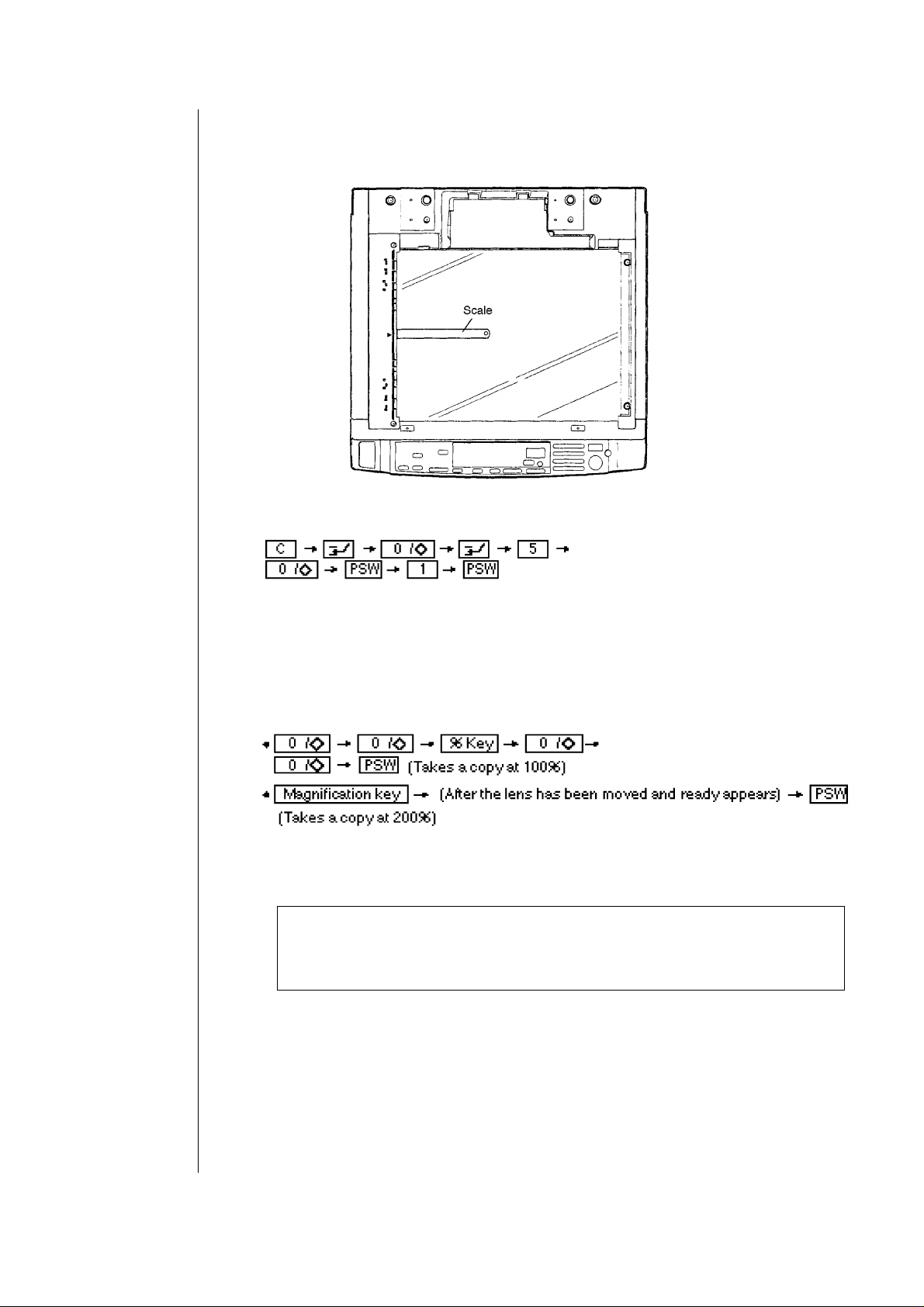
[Carrying out the adjustments using the reference chart]
(Adjustment instructions)
á Place the scale marker on the manuscript unit.
í
Press the keys in the order indicated above. (Simulation 50 will commence) The
READY lamp will come on and the value previously entered (anything from 1-99) will be
displayed. This is the RRC-A information.
ó Set the values for A and B and then make copies at 100% and then 200%.
ú Measure the distance from the edge of the paper to the end of the scale measure, and
find the values for RRC-A and RRC-B, as explained below.
If the preset value for RRC-A is not correct, the positioning of copies at different
magnifications will differ. RRC-B is a preset value which is designed to adjust the
timing of when the RRC goes on, so that the front of the copy will match the front
of the image on the drum.
2/5
Page 3

The front of the
image of the
scale measure
The front of the
image of the
scale measure
Copy made at
actual size( x 1.00)
• L1: Distance at 200% (mm)
• L2: Distance at 100% (mm)
Copy made at a
magnification (x 2.00)
Measure L1 and L2, and then use the chart to check them against the values in RRC-A
and RRC-B.
(Example) L1 = 23 mm L2 = 16 mm
RRC-A = 43
RRC-B = 69
a) Press the % key until the counter display shows ‘‘A 0"
b) Enter the values shown below to set the values for RRC-A and RRC-B.
Proceed according to the instructions from b) in the service manual in order to complete
the adjustments.
3/5
Page 4

4/5
Page 5

Ref.
Model
No.
SF-2116
SF-2118
<Interchange>
1. Interchangeable. 4. Not interchangeable.
2. Current type can be used in place of new type.
3. Current type cannot be used in place of new type.
Parts marked with ‘‘ ’’ is important for maintaining the safety of the set. Be sure to replace these parts with
specified ones for maintaining the safety and performance of the set.
Version P/G No.
name
All 29 -54 VHI27C01045FC VHI27C01060FC BA IC [IC7]
New type cannot be used in place of current type.
New type can be used in place of current type.
Current parts New parts
Parts code Parts code
5. Interchangeable if replaced with same types of
6. Others.
Price
related parts in use.
Parts name
rank
Effec-
tive
time
1st lot
’95/7
Inter-
change-
ability
3
Note
5/5
 Loading...