

Page 1
Date: Dec. 12, 1994
COPIER : SF-2014
No. : SP-1844
PARTS GUIDE CORRECTIONS
1.Model name: SF-2014, 2114, 2214
2.General: Part’s code changes and new parts setting are made in above models due to the
change of parts’ forms. We already have been made them from the first unit of mass
production. Please correct and add descriptions to the parts guide.
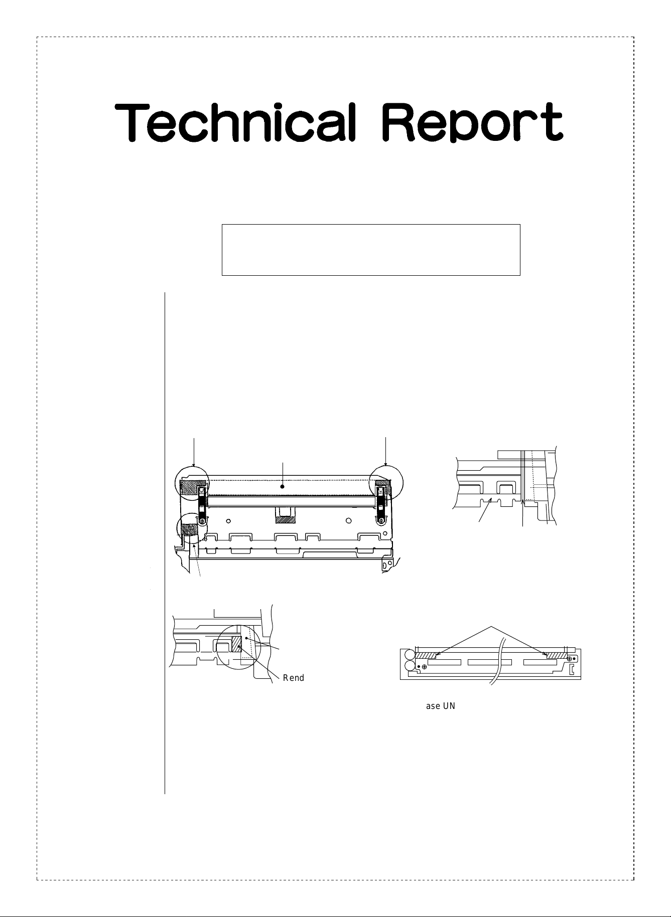
3.Description: 1. Add mylars to the upper frame and the TC case unit
DV base plate bottom molt RD
(added)
DV lower guide plate
Base plate molt R
DV base plate rend seal
Rend mylar (added)
DV base plate bottom molt RD
(added)
DV lower guide plate DV base plate
rend seal (added)
TC molt (added)
TC case UN back diagram
2. Change of screws inside the toner hopper unit
SHARP CORPORATION Reprography Division
1/5
Green
C
Page 2
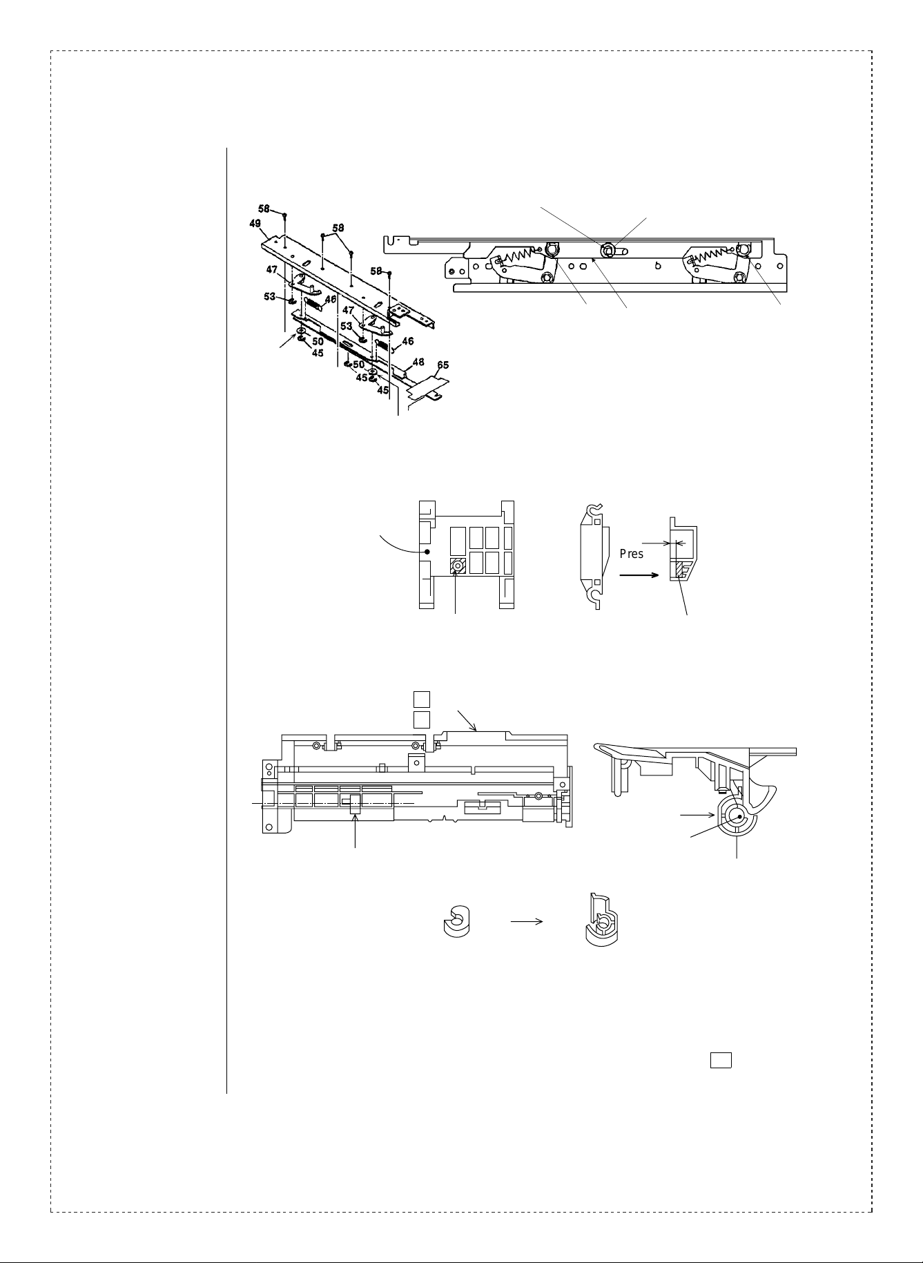
3. Addition and discontinuance of the E ring washer inside the developing unit
E3
Discontinued
Discontinued
Plane head washer φ4 (added)
XWHSD40-08100
E3
DV joint plate N
LPLTM4739FCZZ
4. Change of the limiter spring and addition of weight to the paper feeding holder inside
the cassette paper feeding unit
Paper feeding roller holder
3.5
Pressed
into
E3
2/5
Weight for paper feeding Weight for paper feeding
5. Addition of the paper feeding guide inside the cassette paper feeding unit
51 -30
52 -901
Flatted side
Guide spacer
Paper feeding guide
Temporary measure Permanent measure
Paper feeding roller shaft
Paper feeding guide
Remove the guide spacer when you exchange the temporal paper feeding guide which
attached to the 250 cassette paper feeding unit with the permanent one.
Exchange the temporal paper feeding guide of SF-CM14 (the second cassette paper
feeding unit) to the permanent one with the second paper feeding frame ( 52 -27)
because its guide spacer needs the rib.
Page 3

6. Addition of the manual feeding sheet mylar to the manual multi paper feeding unit
,,
,
Manual feeding sheet mylar
Manual feeding sheet ( 17 -27)
7. Addition of douse sheet to the BL holder
Douse sheet A
Cross
section A-A
A
A
BL holder
5 -23
Subtend to the rib
position in 0 ±0.5
Push it to this rib to attach.
8. Parts code changes of the joint seal BN inside the toner hopper unit
9. Addition of the polyslider inside the toner hopper unit
Polyslider φ6 (added)
Toner holde r 10 - 8
10.Addition of the sheets inside the SF-CM14 (250 cassette module unit)
Second cassett e gui de R 51 -18
MG auxiliary sheet
PSHEP3790FCZZ (added)
3/5
Page 4

Second cassette paper feeding unit
51 -30
2nd brake sheet (added)
PSHEZ3789FCZZ
Insert it to
this hall
4/5
Paper feeding clutch
Noise insulation sheet
PSHEZ3791FCZZ
(Added)
Roll up both projected sides
Page 5

Ref.
No.
Model
name
Version P/G No.
Current parts New parts
Parts code Parts code
Price
rank1
Parts name
Effec-
tive
time
Inter-
change-
ability
Note
1
2
3
4
5
SF-2014
SF-2114
SF-2214
5
5
5
5
5
15 —
10 -30
9 -50
9
All
18 -30
52 -14 —
18
52 —
18
52 —
— PMLT-0959FCZZ AB
— PMLT-0960FCZZ AB
— PMLT-0961FCZZ AB Base plate molt R —
— PSEL-0641FCZZ AA
— PSHEP3778FCZZ AG Rend mylar —
PMLT-0962FCZZ
(Q’ty: 2)
XEBSD30P12000 XEPSD30P12000 AA Screw (M3x12) —
XWHSD40-08000
(Q’ty: 2)
— XWHSD40-08100 AA Washer —
MSPRC2202FCZZ MSPRC2202FCZ1 AD spring 250
— PWET-0027FCZZ AE
— PGIDM1578FCZZ AD
(Discontinued) — Washer —
DV base plate
bottom molt FD
(added)
DV base plate
bottom molt RD
(added)
DV base plate
rend seal
AA TC molt —
Weight for paper
feeding
Paper feeding
guide
—
—
—
1st lot.
—
—
—
6 SF-MF14 17 — PSHEP3760FCZZ AB
7
SF-2014
8
SF-2114
SF-2214
9 10 —
SF-CM14
10
SF-CM11
<Interchange>
1. Interc ha ng ea bl e. 4. N ot i nt er ch an ge ab l e.
2. Current type can be used in place of new type.
New type cannot be used in place of current type.
3. Current type cannot be used in place of new type.
New type can be used in place of current type.
Parts marked with “ ” is important for maintaining the safety of the set. Be sure to replace these parts with
specified ones fo r m ain ta in i ng t he s a fe ty an d pe r fo rma nc e o f th e s et .
5
10 -4 PSEL-0594FCZZ PSEL-0594FCZ1 AC Joint seal BN —
51 — PSHEP3790FCZZ AA
51 — PSHEZ3789FCZZ AE 2nd brake sheet —
51 — PSHEZ3791FCZZ AA
!
— PSHEP3808FCZZ AD Douse sheet A —
LX-WZ0186FCZZ
(Q’ty: 2)
5. Interchangeable if replaced with same types of
relate d parts in use .
6. Others .
Manual feeding
sheet mylar
AA Polyslider —
MG auxiliary
sheet
Noise insulation
sheet
—
—
5/5
 Loading...