

Page 1
Date: Dec. 28, 1993
OPTION : SF-S51
No. : SP-1660
SF - S51
TROUBLE SHOOTING THE STAPLE DRIVE OF
THE STAPLE UNIT (BLANK SHOTS)
1.General: The opening in the faceplate for the staples is sometimes a little small, preventing the
staples from being driven properly when using staple modes (staple sort and manual
staple modes). By changing the shape of the feeder the staple driving force is
increased sufficiently so that the staples can be driven, even if the opening in the
faceplate should be a little small.
2.Cause: The opening for the staples is sometimes too small, due to manufacturing irregularities
in the parts of the staple unit face plate. This increases friction resistance, which
prevents the staples from being driven. (irregularities in the dimensions of the mold for
the faceplate occurred when it was renewed in March of 1993.)
Burrs (unpolished edges) sometimes remain on the staple openings of the faceplate
after manufacturing. The trouble mentioned above also occurs when the staples get
caught on these burrs.
* Dimension irregularities are the main cause of stapling trouble. Only a small
percentage of the stapling trouble is caused by burrs remaining on the staple opening
of the faceplates.
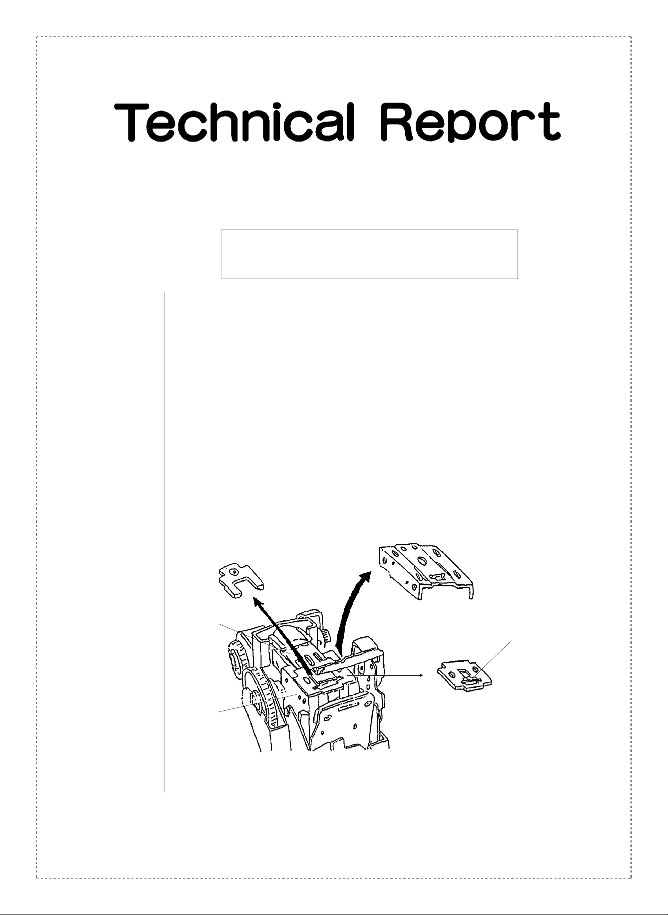
FRONT SHEATH
FORMER
DRIVER PLUNGER
FACE PLATE
Location of the staple opening
dimension irregularities.
BODY
SHARP CORPORATION Reprography Division
1/7
Green
C
Page 2
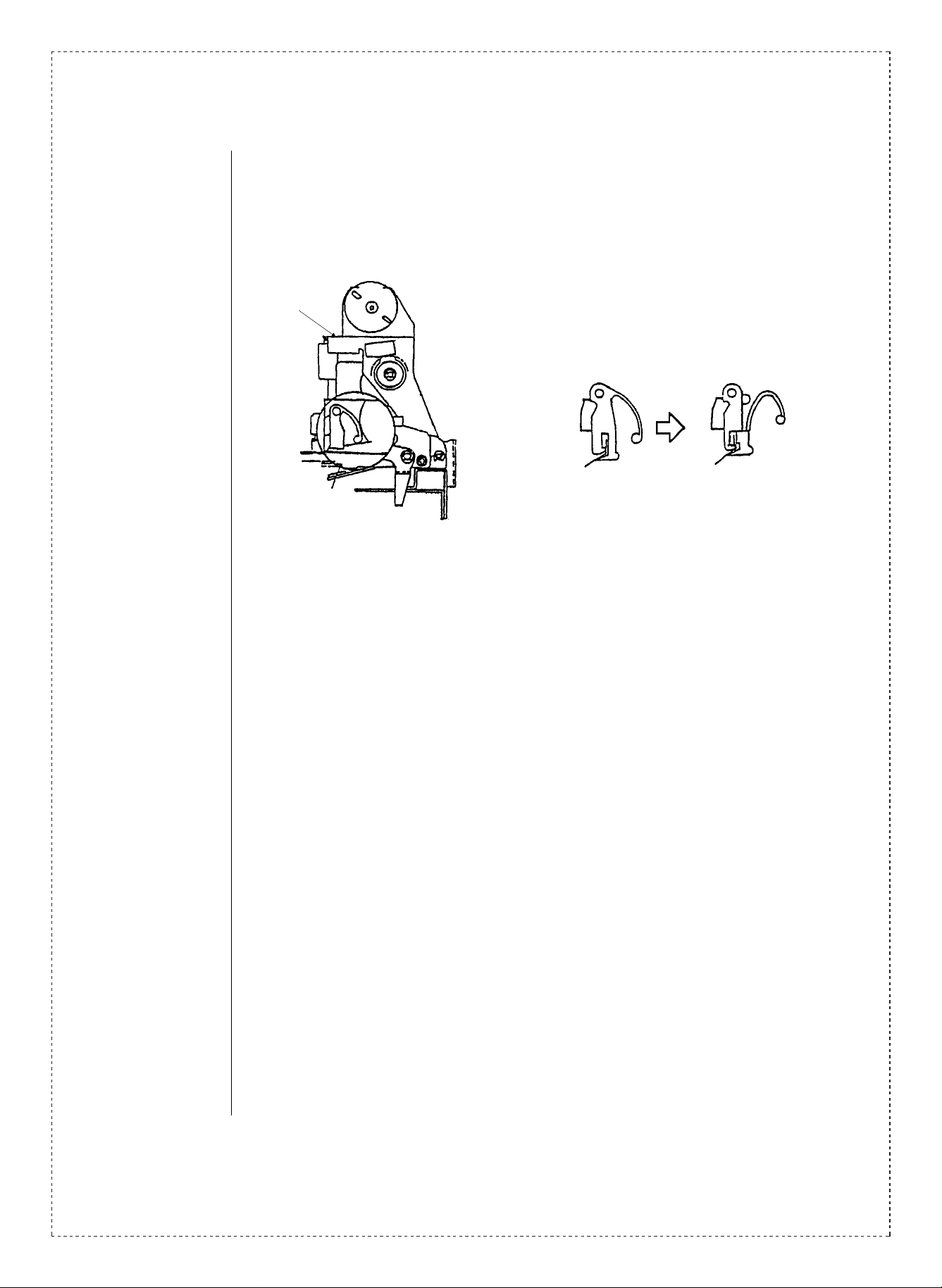
3.Description: ➀ The shape of the feeder spring has been changed. This has improved the driving
power applied to the staples, enabling them to be driven with no problem, even if the
dimensions of the staple opening in the faceplate is small.
➁ Burr removal and rechecks of the faceplate.
* φ0.5 blue seal.
(Old type.) (New type.)
* To distingusish which units have had
these changes carried out, a blue seal
has been affixed.
4.Action: (Factory action)
From 1993 October production.
(Field action)
When trouble occurs, the feeder, faceplate and M-spring should be replaced.
(Replacement parts).
• Feeder (new type).
• Faceplate (properly finished, with burrs removed).
• M-spring (The spring may become deformed when removed, and should therefore be
replaced.)
In regard to the supply of these replacement parts, please contact PQA, Reprographic
Division.
2/7
Page 3
of Countermeasure Parts for Staple Misfeeding Defect
replacemen t parts:
• FEEDER (a part to feed staple belt)
• FACE PLATE (a metal sheet attached to the body)
• M-SHAPED SPRING (a M-shaped wire spring)
Replacement Procedure
1. Disassemble of Stapler Unit
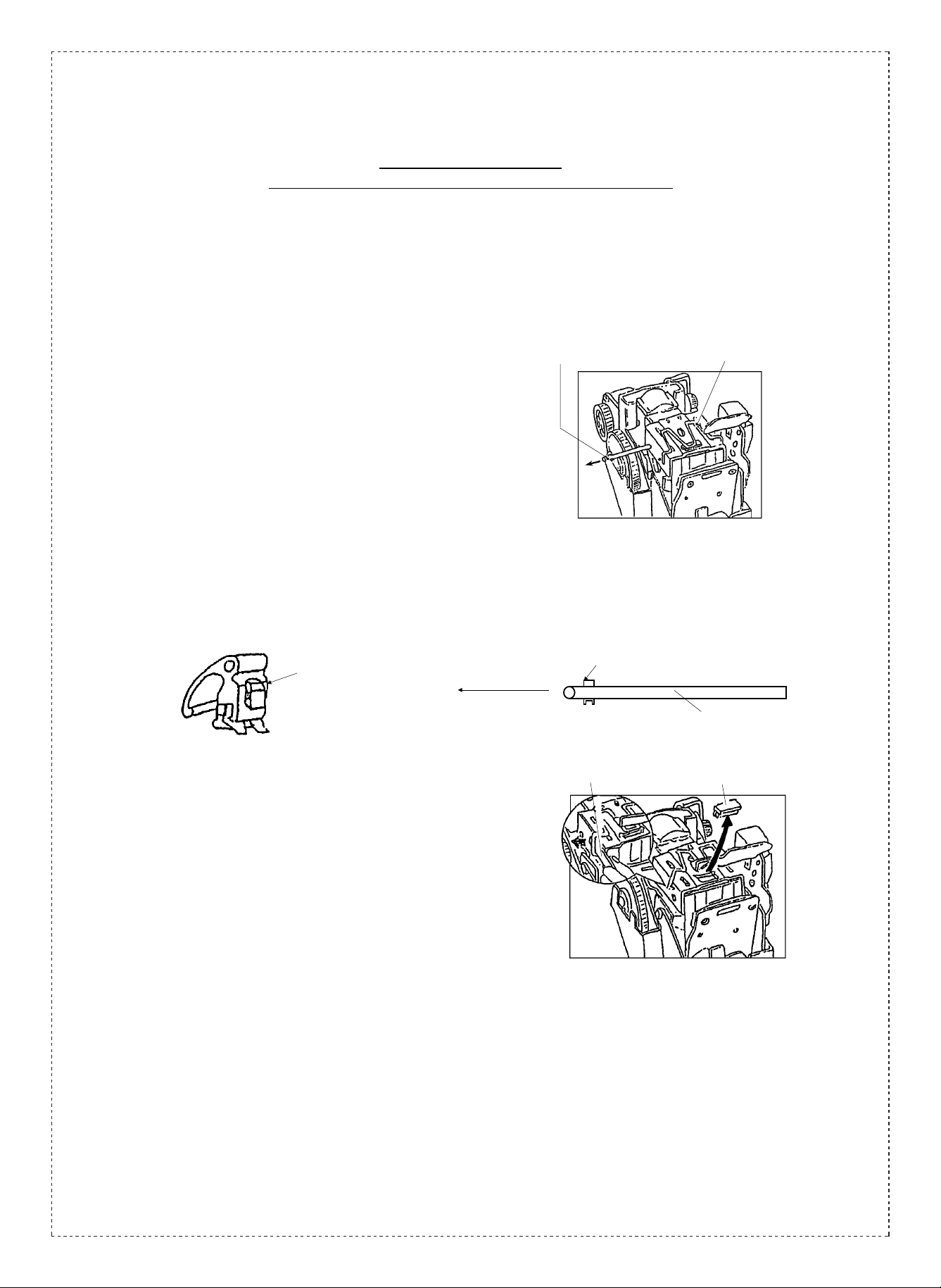
➀ Pull out BODY PIN toward the arrow mark direction in
Fig.1.
(If you try to pull it to revers e dir ection , it wi ll be s tuck
with ribs.)
• It mak es this operat io n easy to ta p the bot tom of
BODY PIN slight ly wit h any tool such as s crew
driver.
FEEDER is now rem ova ble from the st apler uni t.
FEEDER (current)
pulling direction
BODY PIN
M-SHAPED SPRING
Fig.1
rib
BODY PIN
➁ Remove M-SHAPED SPRING pulling both sides with
any tool such as flat s crew dri ver. (See Fi g.2.)
Also remove BENDING BLOCK at the same time.
•CAUTION!
Do not re-use this M-SHAPED SPRING since it might
be deformed for t his oper ati on.
flat screw driver
BENDING BLOCK
Fig.2
3/7
Page 4

➂ Remove CAR TRIDGE SPRING pu shin g both sid es
from behind th e unit. ( See Fig. 3.)
stapler unit
CARTRIDGE SPRING
CARTRIDGE SPRING
1
2
➃ Remove FRON T SHEAT H and FORMER from th e unit.
➄ Remove curre nt FACE PLATE under DR IVER
PLUNGER.
FRONT SHEATH
FORMER
DRIVER PLUNGER
Fig.3
FACE PLATE (current)
BODY
2.Assemble of Stapler Unit
➀ Put new FACE PLATE on bosses of BODY. (See
Fig.4.)
Make sure the embos sed s ide is up.
NOTE)
Deburring is appl ie d to the entranc e of st aple of new
FACE PLATEs.
4/7
FACE
PLATE
BODY
Fig.4
Page 5

➁ Put FORMER on DRIVER PLUNGER to be the side
having a boss do wn.(See F ig.5. )
side view of FORMER
boss
DRIVER PLUNGER
FORMER
BODY
FACE PLATE
down (back)
up (face)
➂ Put FRONT SHEATH.
➃ Push FRONT S HEATH and assembl e CART RIDGE
SPRING pushin g both s ides .
See figures bel ow as t o loca tion an d dire ction f or
assembly.
((insert direction))
Fig.5
FRONT SHEATH
Fig.6
front
CARTRIDGE SPRING
BODY
((location))
FRONT SHEATH
a hole for cartridge spring
a hole for body pin
a hole for M-shaped spring
5/7
Page 6

➄ Assemble new FEEDER into BODY with BODY PIN
after assembly of CART RIDG E SPRIN G. (It is
impossibl e to assemble FEEDE R before CARTRIDGE
SPRING.)
NOTE)
New FEEDERs have impr oved feed for ce with ne w
configurat ion giv en on it s spr ing. )
1) Put new FEEDER in BODY.
rib
Fig.7
insert direction of body pin
(Adjust the direction of ribs to a hole of body.)
2) Ins ert BODY P IN to hole s of BO DY through
FEEDER. (See Fig.7.)
• It m akes t his op eratio n easy to tu rn the s taple r unit
up side down and hol d FEED ER when insert ing
BODY PIN.
Do not hit BODY P IN hard dur ing i nsert ion, or the
edge of holes mig ht be def ormed.
➅ Assemble BENDING BLOCK and new M-SHAPED
SPRING.
1) Insert BENDING BLOCK into holes of F RONT
SHEATH.
2) Tap the corner of M-SHAPED SPRING with a plastic
hammer af ter insert ing its both sides into holes of
BASE.
BODY
new FEEDER
BODY PIN
a hole for cartridge spring
M-SHAPED SPRING
6/7
3) Insert M-SHAPED SPRING into h oles o f BO DY.
Fig.8
Page 7

Make sure not to ma ke any gap between the si de of
FRONT SHEATH and M-SHAPED SPRING.
Insert correctly
FRONT SHEATH
to make no gap.
• Pleas e use new M -SHAPED SPRING although it does
not have any modif ica tion si nce ol d one mig ht be
deformed for t his oper atio n.
example of deformation
Edge is deformed
(out of use)
Tap here!
BENDING BLOCK
BASE
a hole for M-shaped spring
Angle of corner is deformed.
(out of use)
- end of procedure -
7/7
 Loading...