

Page 1
Date: Dec. 2, 1993
OPTION : SF-A54
1. AUOSW (ADF OPENING AND CLOSING SWITCH) MALFUNCTION
(DOES NOT TURN ON).
2. SEP ARATION BELT PARTS CODE CORRECTION.
3. PRESSING ROLLER STAY CHANGE
(FOR COMPATIBI LTI Y W ITH OTHER MODELS) .
No. : SP-1652
1. Auosw (ADF opening and closing switch) malfunction (does not turn on.)
1.General: When the left side of the SF-A54 (original copy feeding cover, etc.) is pressed during
operations, the right side raises up. The SF-A54 assumes that this means that the DF
cover is open, and shuts down. As a temporary measure, a spacer has been added in
the space between the ADF and the area to the left on the front frame side of the
machine (approximately 3 mm). As a permanent measure, a round hole has been
added to the plate where the spacer has been added, and a rubber support has been
added.
2.Reason: The AUOSW (ADF opening and closing switch) does not turn on.
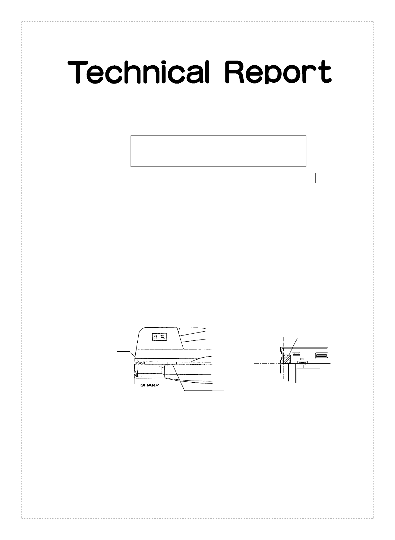
3.Description: Temporary measure: A spacer has been added in the space between the ADF and the
left of the front frame side of the machine. The addition of the
spacer prevents the right side from raising up, even if the left side
is pressed down.
Standard line.
Spacer.
Standard line.
Magnetic catch.
Spacer.
(0CW2158P505A/)
Permanent measure: A round hole has been added to the plate where the spacer has
been added, and a rubber support has been added (from 1993
February production).
SHARP CORPORATION Reprography Division
1/4
Green
C
Page 2
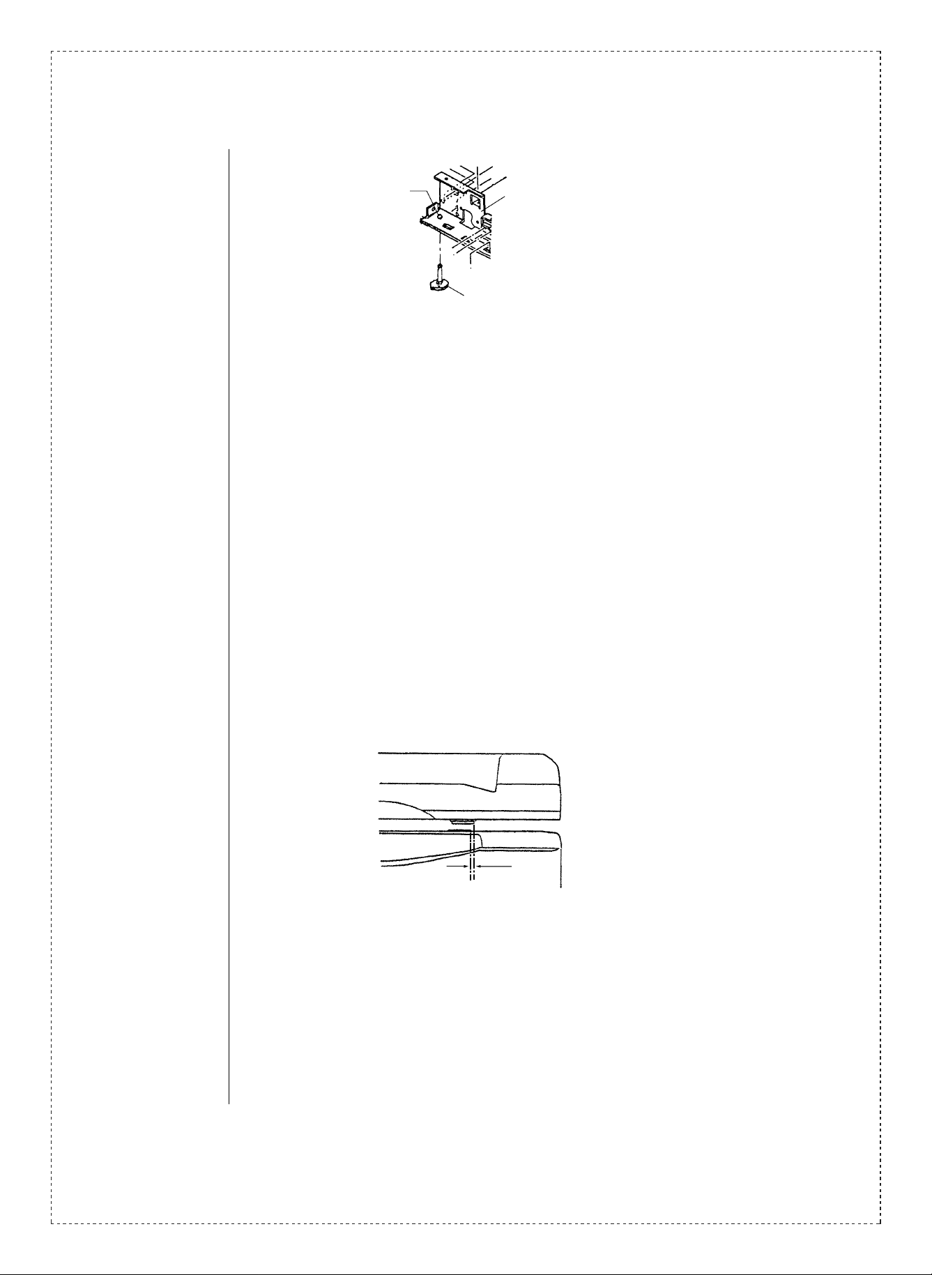
Added hole.
Note: The rubber support cannot be installed on the old side plate F due to the
caulking.
4.Effective time: (Factory action):
Temporary measure:
Between 1992 November production and 1993 January production.
Permanent measure:
From 1993 February production.
* Note: In addition to the problem of the AUOSW not turning on as described above, the
same problem has occurred, caused the right side of the front of the ADF
raising up due to distortion of the hinge during installation of the A54.
To prevent this from happening, the following installation points are provided.
Changed side plate F1 assembly
(a round hole has been added).
Added rubber support.
[Installati on poi nt s ]
➀ Installation procedures should be carried out in proper sequence. (Please refer to
the installation manual.)
➁ After installation has been finished, the relative positions of the magnetic catch and
the MG plate should be checked. (If the relative positions are in line, the installation
is OK. If they are not in line, move on to 3)below.)
SF-2022
Improper
alignment.
➂ Loosen the fixing screw of the hinge ADF on the right side.
➃ Next, press the hinge in the direction which will properly align the magnetic catch
and the MG plate, and tighten the fixing screw. Once again check the relative
positions of the magnetic catch and the MG plate, to make sure they are properly
aligned.
2/4
Page 3

Fixing screw.
2. Separation belt parts code correction. (Overseas)
1.General: There were mistakes in the parts codes for the separator belt, and they have been
corrected.
2.Description: Mistaken.
Separator belt 0CW2166P317B/ Grey
Corrected.
Separator belt 0CW2166P492A/ Black
3. Pressing roller stay change (For compatibiltiy with other models.)
1.General: The pressing roller stay has been changed for the reasons described below.
2.Reasons: To establish metal mold compatibility with other models.
3.Description: A bearing hole has been added in one place to the present pressing roller stay.
The parts code has also been changed accordingly.
Current New
0CW2158P171A/ 0CW2158P171C/
4.Effective time: (Factory action)
Natural conversion from 1993 November .
3/4
Page 4

Ref.
Model
No.
1
SF-A54 All
2
3
<Interchange>
1. Interchangeable. 4. Not interchangeable.
2. C urr e nt t y pe c a n be u s ed i n p la ce of new ty pe .
New ty pe cann ot be us ed i n place of curr ent type .
3. C urre nt ty pe cann ot be used i n place of new ty pe.
New t y pe c a n be u sed in p lac e of c u r ren t ty p e.
Parts m ar ke d wi t h “ ” is imp or t an t fo r m a in ta ini ng t he s a fe ty of the set. B e s u re to r e plac e t he s e pa rts wi t h
specified ones for maintaining the safety and performance of the set.
name
Version P/G No.
2 -42
2
3
1 -79
2 -27
!
Current parts New parts
Parts code Parts code
0CW2158K030B/ 0CW2158K030C/ BA
— 0CW2158P504A/ AH Rubber support. —
— 0CW2158P505A/ AK Spacer. — —
0CW2166P317B/ 0CW2158P492A/ AR Separator belt. — 1
0CW2158P171A/ 0CW2158P171C/ AQ
Price
5. Interchangeable if replaced with same types of
relate d parts in use .
6. Others.
Parts name
rank
Side plate F
caulking.
Pressing roller
stay.
Effec-
tive
time
See
text.
Natural
conver-
sion.
Inter-
change-
ability
3
1
Note
Field
parts
only.
4/4
 Loading...