

Page 1
q
SERVICE MANUAL
Digital copier
MODEL
CONTENTS
CODE : 00Z
ARD25//A1E
: Paper feed unit
250-sheet paper
AR-D24
AR-D25
feed unit
500-sheet paper
feed unit
[1] PRODUCT OUTLINE . . . . . . . . . . . . . . . . . . . . . . . . . . . . . . . . . . 1
[2] SPECIFICATIONS . . . . . . . . . . . . . . . . . . . . . . . . . . . . . . . . . . . . 1
[3] UNPACKING AND INSTALLATION . . . . . . . . . . . . . . . . . . . . . . . 2
[4] EXTERNAL VIEW AND INTERNAL STRUCTURE . . . . . . . . . . . 8
[5] OPERATIONAL DESCRIPTION. . . . . . . . . . . . . . . . . . . . . . . . . . 9
[6] DISASSEMBLY AND ASSEMBLY . . . . . . . . . . . . . . . . . . . . . . . . 9
[7] MAINTENANCE . . . . . . . . . . . . . . . . . . . . . . . . . . . . . . . . . . . . . 11
[8] ELECTRICAL SECTION. . . . . . . . . . . . . . . . . . . . . . . . . . . . . . . 12
Parts marked with "!" are important for maintaining the safety of the set. Be sure to replace these parts with specified
ones for maintaining the safety and performance of the set.
This document has been published to be used
SHARP CORPORATION
for after sales servic e only.
The contents are subject to change without notice.
Page 2

Page 3
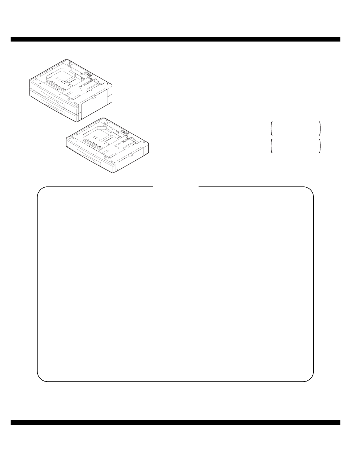
[1] PRODUCT OUTLINE
The 250-sheet paper feed unit and the 500-sheet paper feed unit are
the optional paper feed cassettes for the digital copier, and they are the
same structure as the 250-sheet cassette of the copier.
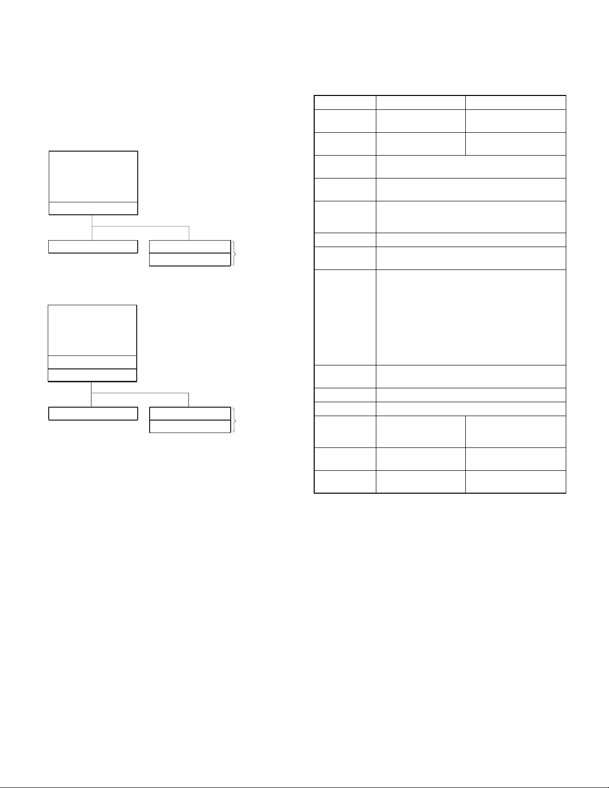
The combination of the copier and the paper feed cassette is as shown
below:
Copier
(1-Tray Model)
Standard cassette
250-sheet paper feed unit
Copier
(2-Tray Model)
Standard cassette
Standard cassette
250-sheet paper feed unit
250-sheet cassette
250-sheet cassette
250-sheet cassette
250-sheet cassette
500-sheet paper
feed unit
500-sheet paper
feed unit
[2] SPECIFICATIONS
1. Paper feed unit
AR-D24 AR-D25
Paper
feed step(s)
Paper feed
capacity
Size detection None
Paper feed
detection
Paper feed size A3, B4, A4, A4R, B5, B5R
Paper weight 56 ~ 90g/m2 (15 ~ 24lbs)
Shipping size AB series: A4
Size selection
Cassette
detachment
Heater Available only in Japan model
Power source Supplied from the machine.
External
dimension (mm)
Weight About 4.7kg
Power
consumption
1-step 2-step
250 sheets x 1 step 250 sheets x 2 steps
(The paper size is set by the user program.)
Available
11 x 17, 8.5 x 14, 8.5 x 13, 8.5 x 11, 8.5 x 11R,
8K, 16K, 16KR
Inch series: 8.5 x 11
User operation (Si ze set tin g by th e user pro gr am)
Japan: A3, B4, A4, A4R, B5, B5R
Inch series: 11 x 17, 8.5 x 14, 8.5 x 11, 8.5 x 11R
EX AB series: A3, B4, A4, A4R
Inch series foolscap area:
11 x 17, 8.5 x 14, 8.5 x 13, 8.5 x 11,
8.5 x 11R
EX AB series foolscap area:
A3, B4, A4, A4R, 8.5 x 13
Possible by the user
W: 590 x D: 471 x H: 88
(Jut portion is not
included.)
(With cassette)
5.6W 8.4W
W: 590 x D: 471 x H: 173.5
(Jut portion is not
included.)
About 10.0kg
(With cassette)
AR-D25/D24 PRODUCT OUTLINE
– 1 –
Page 4
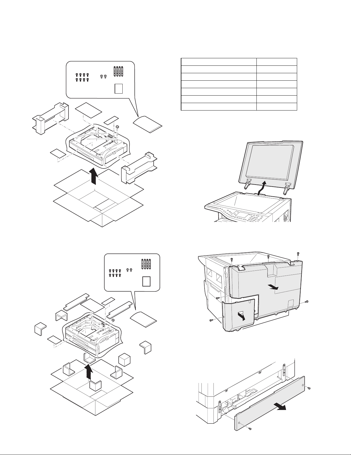
[3] UNPACKING AND INSTALLATION
1. Unpacking
(AR-D24)
2. Installation
Included parts
Part name Quantity
Screw (Fixing plate) 8
Screw 2
Screw 1
Fixing plate 3
Fixing plate 1
Connection gear 1
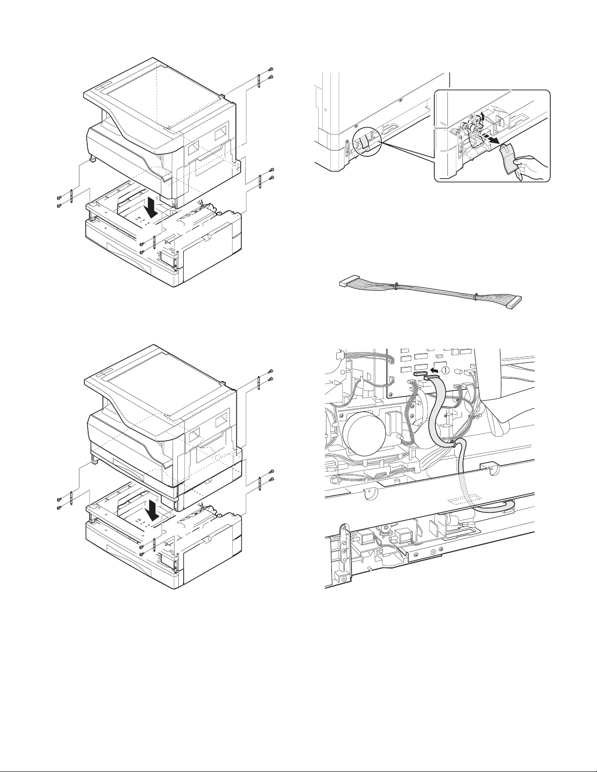
1) Remove the document cover.
Lift the document cover from the copier and tilt it to the rear side to
remove it.
(AR-D25)
2) Remove the rear cabinet.
Remove the screw and remove the cover. Then, remove the five screws
and remove the rear cabinet.
3) Remove the copier rear cover.
Remove the two screws and remove the rear cover.
AR-D25/D24 UNPACKING AND INSTALLATION
– 2 –
Page 5
4) Make a hole for connector.
• Copier (1-tray model)
Cut out the portion shown in the illustration with nippers or the like.
• Copier (2-tray model)
Press the portion shown in the illustration with a screwdriver or the
like to remove it.
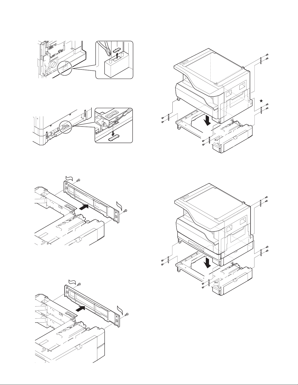
5) Remove the second cassette rear cover.
6) Install the copier onto the 250-sheet paper feed unit.
Put the copier on the 250-sheet paper feed unit, and fix with the fixing
plates and the screws.
• Copier (1-tray model) + 250-sheet paper feed unit
Remove the rear cover which is attached to the 250-sheet paper feed
unit.
Remove the rear cover (upper stage) from the 500-sheet paper feed
unit.
• Copier (2-tray model) + 250-sheet paper feed unit
AR-D25/D24 UNPACKING AND INSTALLATION
– 3 –
Page 6
• Copier (1-tray model) + 500-sheet paper feed unit
7) Remove the connection gear lock.
Remove the connection gear lock (with the red tug) after setting.
8) Connect the connector
Connect the optional relay harness contained in the 1-tray model (2-tray
model) paper feed unit to the PWB of the copier.
• Optional relay harness
• Copier (2-tray model) + 500-sheet paper feed unit
• Copier (1-tray model) + 250-sheet paper feed unit
AR-D25/D24 UNPACKING AND INSTALLATION
– 4 –
Page 7
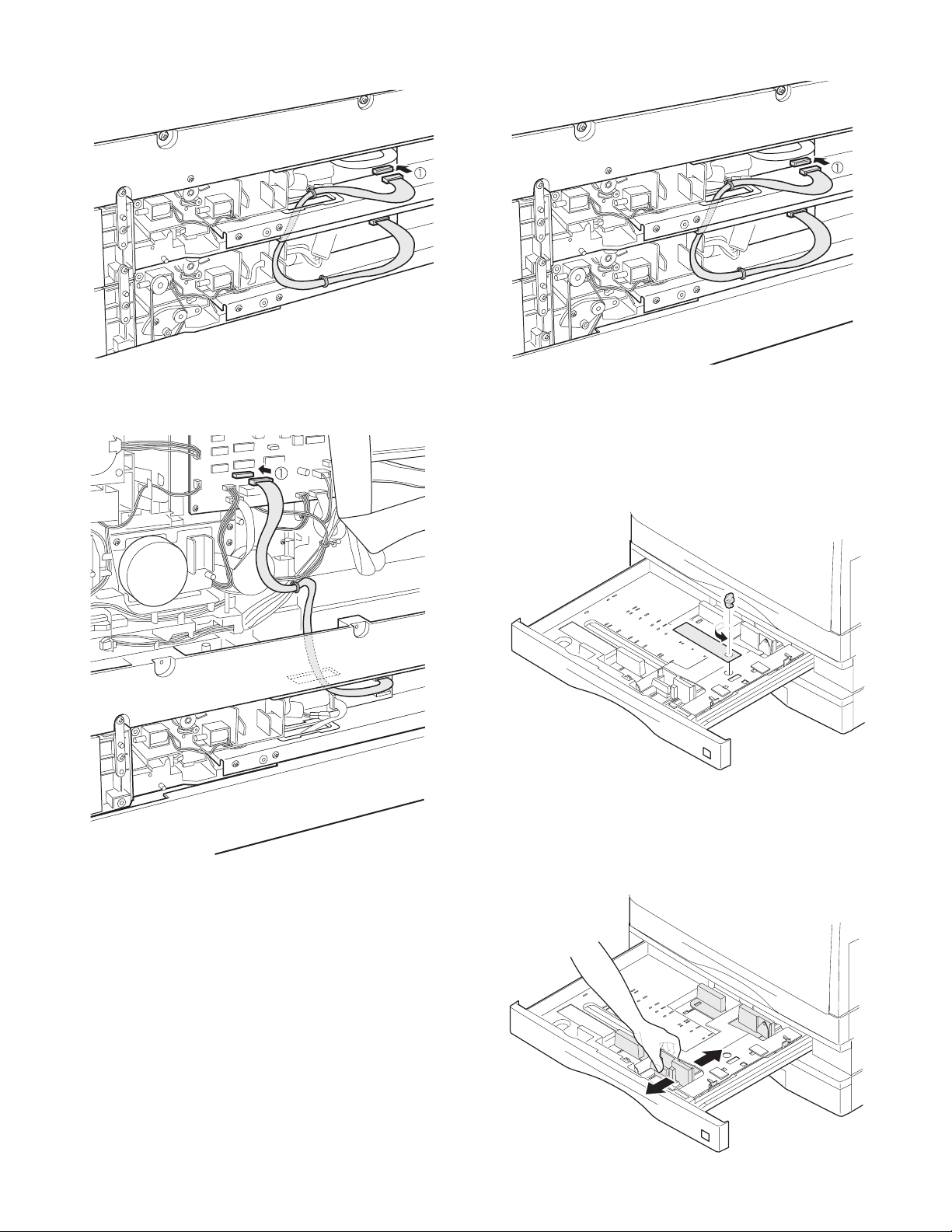
• Copier (2-tray model) + 250-sheet paper feed unit
• Copier (2-tray model) + 500-sheet paper feed unit
• Copier (1-tray model) + 500-sheet paper feed unit
9) Remove the cassette packing fixtures.
Pull the cassette until it stops.
Turn and remove the packing fixture which is fixing the paper pressure
plate inside the cassette in the direction of arrow.
10) Set the cassette side plate.
Hold the knob of the cassette side plate, slide it and set to the position
of the paper size to be used.
AR-D25/D24 UNPACKING AND INSTALLATION
– 5 –
Page 8
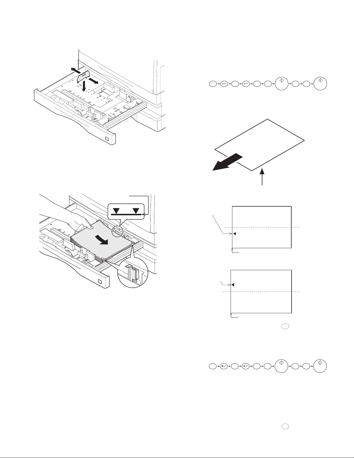
11) Install the cassette rear edge plate.
g
Install the cassette rear plate to the position of the paper size to be
used.
Note: To make the paper center shift adjustment and the lead edge
adjustment, insert the power plug of the copier into the
power outlet, turn on the power switch, and perform the following procedure.
13) Perform the center shift adjustment.
Set a document on the document glass and make a copy.
*If the image center is shifted, perform the following procedure.
1. Execute SIM 50-10 with the key operations on the copier.
12) Set the paper.
When setting the paper, do not exceed the height of the indication label.
cannot stack
more than this line.
[Program key]
#
C 5 0 1 0
2. Turn on the Auto lamp and the lamp of a corresponding tray by
Light and Dark key, Enter the set value with the keys on the operation panel to perform the center shift adjustment, make a copy
again, and check that the center is not shifted.
Rear side
Front side
Paper output direction
Printin
side
• When the s et value is inc reased, the image is shifted to the rear
side.
Center line of image
1
Output direction
Printing side
Center line
of paper
Leading edge
• When the set value is decreased, the image is shifted to the front
side.
Center line of image
1
Output direction
Center line
of paper
Printing side
Leading edge
After completion of the adjustment, press the key to cancel the
CA
mode.
14) Perform the lead edge adjustment.
Set a document on the document glass, and make a copy.
1. Execute SIM 50-1 with the key operations on the copier.
[Program key]
# 1
C 5 0
2. Turn on the Auto lamp and the lamp of a corresponding tray by
Light and Dark key, Enter the set value with the keys on the operation panel and make a copy to check that the lead edge is within the
specified range.
• When the set value is increased, the copy image moves forward.
• When the set value is decreased, the copy image moves backward.
After completion of the adjustment, press the key to cancel the
mode.
0
CA
AR-D25/D24 UNPACKING AND INSTALLATION
– 6 –
Page 9
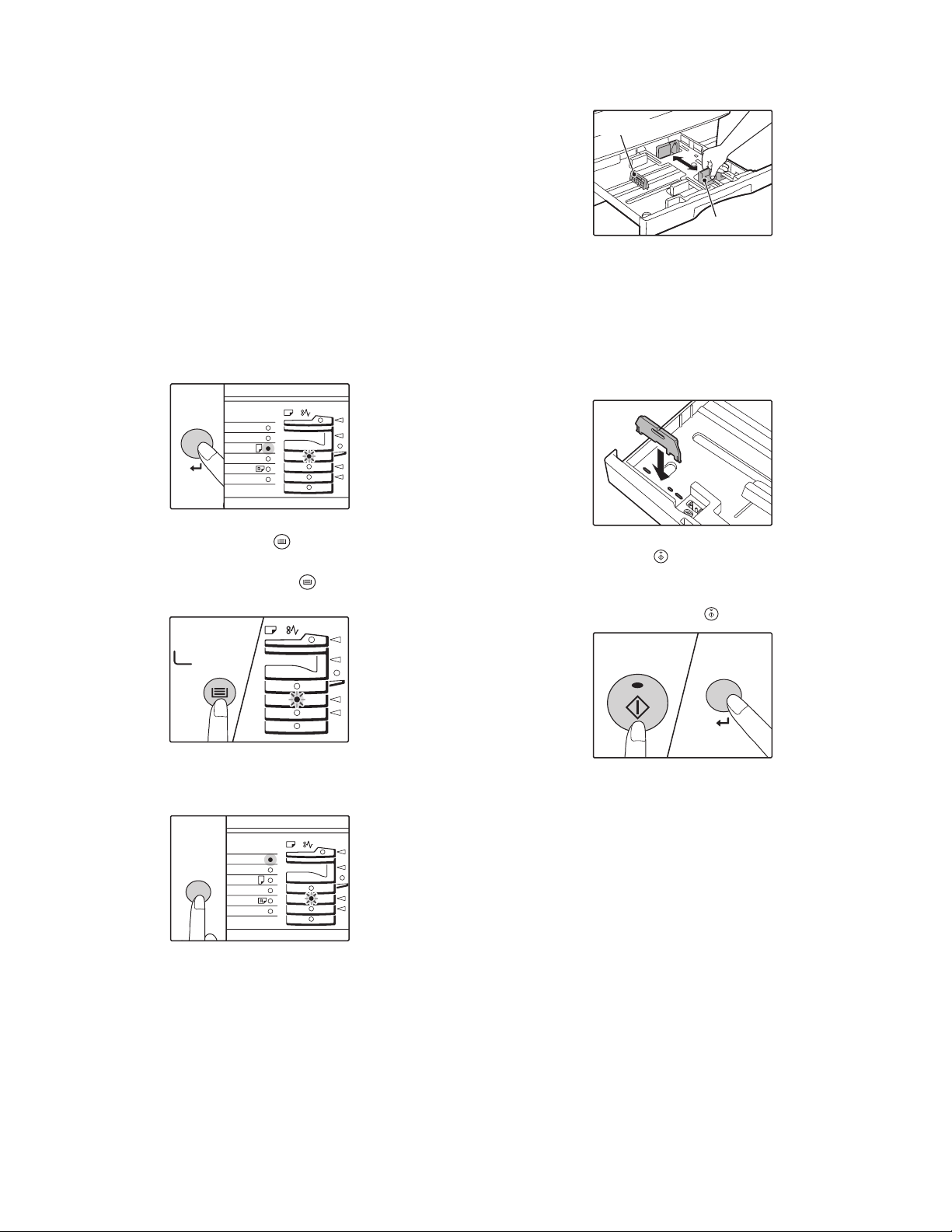
15) Changing a tray’s paper size setting
PAPER
SIZE
11X17
8½
X
14
8½
X
11
8½
X
11
8½
X
5½
EXTRA
TRAY
SELECT
ORIGINAL SIZE
ENTER
PAPER
SIZE
11X17
8½
X
14
8½
X
11
8½
X
11
8½
X
5½
EXTRA
START
Follow these steps to change a tray’s paper size setting.
Note:
• The paper size setting cannot be changed when the machine has
stopped temporarily due to running out of paper or a misfeed, or
during interrupt copying.
• During printing (even in copy mode), the paper size setting cannot
be changed.
• 5-1/2” x 8-1/2” size paper can only be selected in upper paper tray.
• Do not load paper that is a different size than the paper size setting. Copying will not be possible.
1. H old down the [PAPER SIZE ENTER] key for more than 5 seconds
to set the selected paper size.
The currently selected paper feed location indicator will blink and
the corresponding paper size (which is currently set) indicator will
light steadily. All other indicators will go out.
4. Squeeze the lock lever of the front guide and slide the front guide to
match the width of the paper, and move the left guide to the appropriate slot as marked on the tray.
Left guide
Front guide
• The front guide is a slide-type guide. Grasp the locking knob on
the guide and slide the guide to the indicator line of the paper to
be loaded.
• The left guide is an insert-type guide. Remove it and then insert it
at the indicator line of the paper to be loaded.
• Whe n using 11” x 17” sized paper store the left guide in the slot
at the left front of the paper tray.
2. Use the [TRAY SELECT] key ( ) to select the paper tray for
which you wish to change the paper size setting.
Each time the [TRAY SELECT] key ( ) is pressed, a paper tray
will be indicated with a blinking paper feed location indicator.
3. U se the [ORIGINAL SIZE ENTER] key to select the paper size.
The indicator of the selected paper size lights up.
5. Press the [START] key ( ) and then the [PAPER SIZE ENTER]
key.
To change0 the paper size setting of another tray, repeat steps 2 to
3 after pressing the [START] key ( ).
Note: Affix the paper size label for the paper size selected in step 3 to
the label position on the right end of the tray.
AR-D25/D24 UNPACKING AND INSTALLATION
– 7 –
Page 10
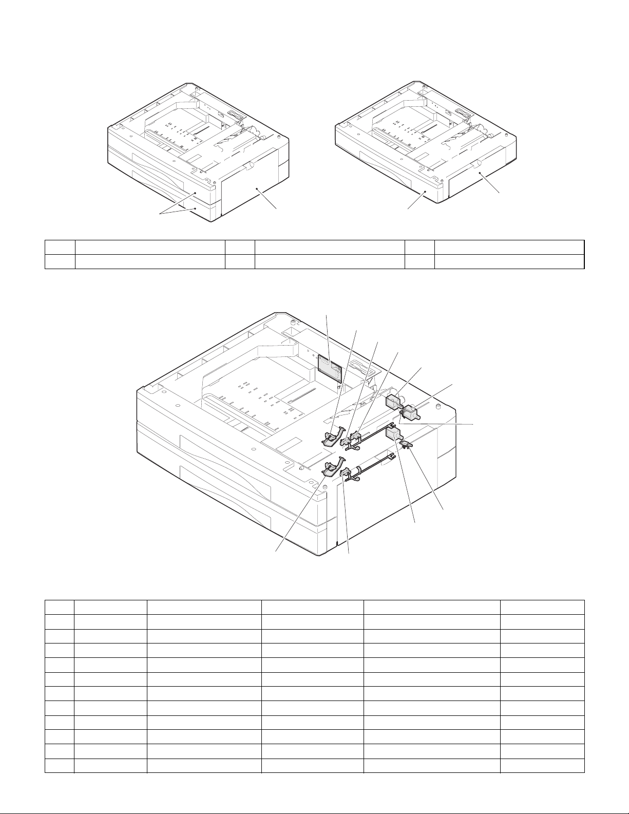
[4] EXTERNAL VIEW AND INTERNAL STRUCTURE
1. External view
3
1
No. Name No. Name No. Name
1 Paper feed tray 2 2-step paper feed right cover 3 1-step paper feed right cover
2
2. Internal structure
11
3
1
2
1
6
5
4
9
10
8
Sensors and detectors
No. Code Name Type Function, operation Remark
1 DRS1 Door open/close sensor Photo transmission Detects door open/close.
2 PPD1 Paper entry sensor Photo transmission Detects paper transport.
3 CSS1 Paper empty sensor Photo transmission Detects paper presence/empty.
4 CASS1 Cassette detection SW Contact Detects cassette installation.
5 FSOL1 Transport solenoid DC solenoid Transports paper. (for clutch)
6 PSOL1 Paper feed solenoid DC solenoid Feeds paper. (For clutch)
7 PPD2 Paper entry sensor Photo transmission Detects paper transport. AR-D25 only
8 CSS2 Paper empty sensor Photo transmission Detects paper in the cassette. AR-D25 only
9 CASS2 Cassette detection SW Contact Detects cassette installation. AR-D25 only
10 PSOL2 Paper feed solenoid DC solenoid Feeds paper. AR-D25 only
11 PWB Interface PWB — —
7
AR-D25/D24 EXTERNAL VIEW AND INTERNAL STRUCTURE
– 8 –
Page 11
[5] OPERATIONAL DESCRIPTION
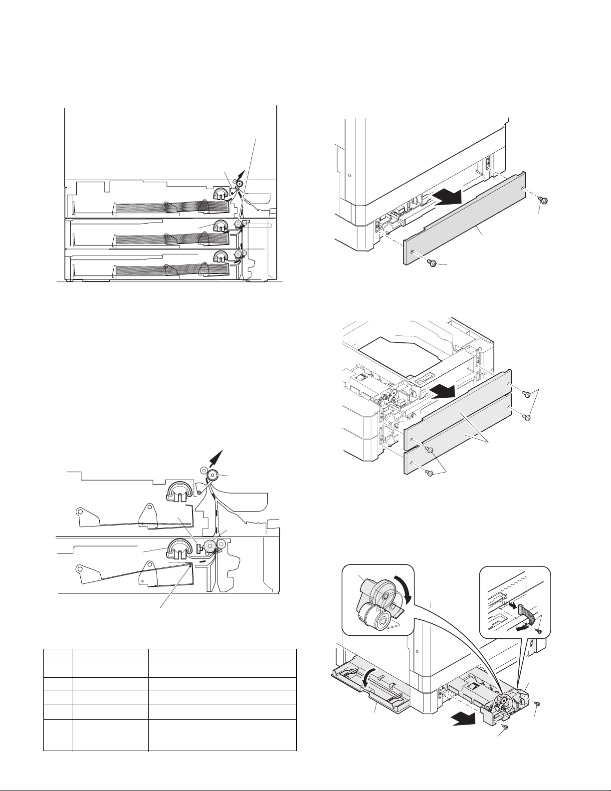
[6] DISASSEMBLY AND ASSEMBLY
1. Paper transport path
Transport roller
PF sensor
Copier
cassette
250-sheet paper
feed unit (upper)
250-sheet paper
feed unit (Lower)
Paper feed roller
2. Operational descriptions
The operations are controlled by the main body of the copier. the paper
feed roller (semi-circular roller) and the transport roller are driven by the
gear of the copier.
Paper is separated by the paper feed roller and the separation pawl,
and detected by the PF sensor, then transported to the Resist roller by
the transport roller.
1. Rear cover
[AR-D24]
1
2
1
[AR-D25]
1
To copier's PS
5
Copier
4
3
1
2
250-sheet paper feed unit
Paper lead edge
No. Name Operation
1 Paper feed roller Picks up paper.
2 Separation pawl Prevents against double feed of paper.
3 Transport roller Transports paper.
4 Paper entry sensor Detects paper transport.
5 Resist roller Makes synchronization between the
paper lead edge and the image lead
edge.
1
2. Paper feed unit section
[AR-D24]
4
2
2
1
5
3
3
AR-D25/D24 OPERATIONAL DESCRIPTION
– 9 –
Page 12

[AR-D25]
4. Transport roller gear section
5
1
1
6
3
2
6
3
4
3. Paper feed solenoid, transport solenoid
2
2
1
5. Transport roller
[AR-D24]
(3)
(2)
(1)
B
A
(1)
1
AR-D25/D24 DIS ASSEMBLY AND AS SEMBLY
– 10 –
Page 13

[Only the upper row of AR-D25]
(3)
(2)
(1)
B
A
6. Paper feed roller clutch
7. Paper feed roller
(1)
1
Note: When asembling the paper feed roller cluch, fit and insert section
A (D cut) into the shaft as shown in the figure.
A
2
1
3
2
*Be sure to rotate this part 180 degrees(It turns upward) after attach-
ment.
[7] MAINTENANCE
No. Name Work item
1 Paper feed roller PA ass’y *1 Cleaning o
2 Transport roller Cleaning o
*1 : Replace = 150K
service call
1
When
Remark
Note: For disassembly and assembly of the paper feed r oller and the
AR-D25/D24 MAINTENANCE
– 11 –
2
transport roller, refer to [6] DISASSEMBLY AND ASSEMBLY.
Page 14

D
C
B
A
1/1
12345678
2 1
24V
5V2
5V2
24V
5V2
24V
5V2
5V2
2nd/Multi step CS only
Lower connection CS
24V
5V2
5V1
CASS1
5V1
PPD1
IC1
CSS1
DRS1
Data selector
3
SELA
SELB
SELB
PSOL1
24V
IC2
FSOL1
PSOL2
CASS2
PPD2
CSS2
Multi step CS only
3
5V1
Driver array
Data selector
IC3
INTERFACE PWB
Copier body
1. BLOCK DIAGRAM
[8] ELECTRICAL SECTION
D
Y1
PSOL1
FSOL1
PSOL2
Y2
FSOL2
PSOL3
Y3
FSOL3
8 7 6 5 4
C
AR-D25/D24 ELECTRICAL SECTION
– 12 –
B
A
Page 15

D
2. ACTUAL WIRING DIAGRM
12345678
1. 2nd CS TYPE AR-D24
175778-2
1
CASS1
LGND
LGND
PPD1
5V2
LGND
DRS1
5V2
LGND
CSS1
2
DF3-3S-2C
1
2
3
DF3-3S-2C
1
2
3
DF3-3S-2C
1
2
35V2
GY
GY
OR
GY
OR
GY
OR
RD
BL
RD
BL
CASS1
PPD1
DRS1
CSS1
PSOL1
FSOL1
C
B
PHDR-20VS
TO 2ND OR MAIN BODY
(UPPER UN)
PGND
PSOL2
FSOL1
FSOL2
24VY224V
PSOL1
2
5
3
1
7
46
PSOL39FSOL3
LGND
PGND
LGND
10 16814
13
12
11
Y1
SELA
SELB
Y3
17
15
A
5V2
5V120SELC
19
18
2 1
RDRDPK
PK
GYGYGYBRPLPLPLOROR
PKPKPK
BR
GY
BR
OR
PL
LB
24V1
/PSOL1
24V1
/FSOL1
SMP-02V-NCSMR-02V-N
1
2
SMP-02V-BCSMR-02V-B
1
2
1
2
1
2
RD
BL
RD
BL
13
9
16
11
14
15
1
2
3
4
5
6
7
8
10
12
CASS1
LGND
PPD1
5V2
DRS1
CSS1
24V1
/PSOL1
24V1
/FSOL1
N.C.
N.C.
N.C.
N.C.
N.C.
N.C.
123 4 56789
CN-B
(B16B-PHDSS)
1
21 22
24V
24V
PSOL1
FSOL1
FSOL2
PSOL2
PSOL3
CS INTERFACE PWB
2ND CS
CN-C
24V
24V
FSOL3
FSOL2
PSOL2
N.C.
PSOL3
2
5
3
7
6
GY
PK
PGND
PGND
LGND
FSOL3
(B22B-PHDSS)
(B20B-PHDSS)
LGND
PGND13PGND
N.C.
10 16
8
12
11
9
LGND
CN-A
Y2
LGND
BR
1011 12 13 1415 1617 1819 20
Y3
14
BR
Y3Y2Y1
5V2
N.C.
N.C.
SELB
SELC
SELA
5V1
3
N.C.
5V2
5V1
SELB
SELA
SELC
18415
19
17
20
ELP-02V
1
AC100N
AC100L
2
FOR LOWER OPTION CS
ELR-02V
AC100N
AC100L
D
TO 2ND OR MAIN BODY
(UPPER UN)
WH
1
BK
2
ELP-02V
WH
BK
1
2
AC100N
C
ELR-02V
1
2AC100L
2nd CS UNIT
PPD1
DRS1
FSOL1
CASS1
HEATER DH1
JAPAN ONLY
PSOL1
CSS1
UNIT REAR VIEW
PWB
8 7 6 5 4
B
A
AR-D25/D24 ELECTRICAL SECTION
– 13 –
Page 16

D
2. MULTI CS TYPE AR-D25
12345678
C
B
PHDR-20VS
TO 2ND OR MAIN BODY
(UPPER UN)
A
UPPER UNIT
CASS1
CASS1
LGND
LGND
PPD1
PPD1
LGND
DRS1
DRS1
LGND
CSS1
CSS1
PSOL1
FSOL1
LOWER UNIT
CASS2
CASS2
LGND
LGND
PPD2
PPD2
5V2 3
175778-2
1
GY
2
DF3-3S-2C
GY
1
2
OR
35V2
DF3-3S-2C
GY
1
2
OR
35V2
DF3-3S-2C
GY
1
2
OR
35V2
RD
BL
RD
BL
175778-2
1
2
DF3-3S-2C
GY
1
2
OR
24VY224V
2
3
1
RDRDPK
BR
GY
BR
OR
PL
LB
1
2
1
2
SMP-02V-NCSMR-02V-N
1
24V1
2
/PSOL1
SMP-02V-BCSMR-02V-B
1
24V1
2
/FSOL1
SMR-08V-N SMP-08V-NC
BR
GY
GY
BR
OR
CASS2
1
1
LGND
2
2
LGND
3
3
PPD2
4
4
5V2
5
5
RD
BL
RD
BL
BR
BR
13
9
16
11
14
15
1
2
3
4
12
8
10
5
6
7
CASS1
LGND
PPD1
5V2
DRS1
CSS1
24V1
/PSOL1
24V1
/FSOL1
CASS2
PPD2
CSS2
24V1
/PSOL2
N.C.
123 4 56789
24V
24V
CN-B
(B16B-PHDSS)
PGND
FSOL1
PSOL1
5
46
PK
PSOL1
FSOL1
PSOL2
FSOL2
7
PKPKPK
FSOL2
PSOL2
Y1
LGND
PGND
LGND
PSOL39FSOL3
PK
21 22
PSOL3
15
10 16814
13
12
11
GYGYGYBRPLPLPLOROR
BR
GY
1011 12 13 1415 1617 1819 20
PGND
PGND
LGND
LGND
FSOL3
CN-A
(B22B-PHDSS)
CS INTERFACE PWB
MULTI CS
5V2
SELA
SELB
Y3
5V120SELC
19
17
18
BR
2 1
SELB
SELC
SELA
Y3Y2Y1
5V1
5V2
N.C.
N.C.
3
CSS2
PSOL2
PPD1
DRS1
FSOL1
CASS1
PPD2
CASS2
LGND
1
CSS2
2
5V2
3
MULTI CS UNIT
CSS1
PSOL1
CSS2
PSOL2
DF3-3S-2C
GY
OR
RD
BL
PWB
GY
LGND
6
LB
CSS2
7
OR
5V2
8
SMR-02V-N SMP-02V-NC
RD
24V1
1
BL
/PSOL2
2
UNIT REAR VIEW
UPPER UNIT
LOWER UNIT
6
7
8
1
2
LB
RD
BL
ELP-02V
1
2
TO 2ND OR MAIN BODY
(UPPER UN)
AC100N
AC100L
ELP-02V
WH
BK
1 AC100N
AC100L
2
ELR-02V
1
2
UPPER CS
HEATER DH2
LOWER CS
1
ELP-02V
1 AC100N
AC100L 2
2
ELR-02V
HEATER DH3
JAPAN ONLY
8 7 6 5 4
D
C
B
A
AR-D25/D24 ELECTRICAL SECTION
– 14 –
Page 17

D
C
B
A
12345678
2 1
3
3. INTERFACE PWB CIRCUIT DIAGRAM
D
C
AR-D25/D24 ELECTRICAL SECTION
– 15 –
8 7 6 5 4
B
A
Page 18

4. PARTS ARRANGEMENT
AR-D25 PARTS ARRANGEMENT
[PARTS SURFACE]
/PSOL1
2
B16B-PHDSS
24V1
1
CN-B
CN-C
11
13
15
17
19
1
3
5
7
9
B20B-PHDSS
24V
PSOL2
PSOL3
N.C.
PGND
LGND
Y2
N.C.
SELB
5V1
2
24V
4
FSOL2
6
FSOL3
N.C.
8
10
PGND
12
LGND
14
Y3
16
SELA
18
SELC
20
5V2
/FSOL1
4
24V1
3
/PSOL2
6
24V1
5
PPD2
8
N.C.
7
CSS2
10
LGND
9
CASS2
12
5V2
11
DRS1
14
CASS1
13
PPD1
16
CSS1
15
CN-A
1
5
7
9
11
13
15
17
19
21
B22B-PHDSS
24V
PSOL1
PGND
LGND
FSOL1
Y1
5V1
5V2
PSOL3
FSOL2
FSOL3
[SOLDER SURFACE]
2
24V
PSOL2
43
6
PGND
LGND
8
10
Y2
12
SELB
14
N.C.(5V1)
16
N.C.(5V2)
18
SELC
20
SELA
22
Y3
AR-D24 PARTS ARRANGEMENT
[PARTS SURFACE]
/PSOL1
2
B16B-PHDSS
24V1
1
CN-B
CN-C
11
13
15
17
19
1
3
5
7
9
B20B-PHDSS
24V
PSOL2
PSOL3
N.C.
PGND
LGND
Y2
N.C.
SELB
5V1
2
24V
4
FSOL2
6
FSOL3
N.C.
8
10
PGND
12
LGND
14
Y3
16
SELA
18
SELC
20
5V2
/FSOL1
4
24V1
3
/PSOL2
6
24V1
5
PPD2
8
N.C.
7
CSS2
10
LGND
9
CASS2
12
5V2
11
DRS1
14
CASS1
13
PPD1
16
CSS1
15
CN-A
1
5
7
9
11
13
15
17
19
21
B22B-PHDSS
24V
PSOL1
PGND
LGND
FSOL1
Y1
5V1
5V2
PSOL3
FSOL2
FSOL3
[SOLDER SURFACE]
2
24V
PSOL2
43
6
PGND
LGND
8
10
Y2
12
SELB
14
N.C.(5V1)
16
N.C.(5V2)
18
SELC
20
SELA
22
Y3
AR-D25/D24 ELECTRICAL SECTION
– 16 –
Page 19

q
AR-D25
PARTS GUIDE
デジタル複合機オプション
デジタル複合機オプション
デジタル複合機オプションデジタル複合機オプション
1111 段給紙デスク
段給紙デスク
段給紙デスク段給紙デスク
2222 段給紙デスク
段給紙デスク
段給紙デスク段給紙デスク
Digital Copier
Digital Copier Option
Digital CopierDigital Copier
Stand/1
Stand/1×
Stand/1Stand/1
Stand/2
Stand/2 ×××× 250 Sheet Paper Drawer
Stand/2Stand/2
× 250 Sheet Paper Drawer
250 Sheet Paper Drawer
××
250 Sheet Paper Drawer250 Sheet Paper Drawer
250 Sheet Paper Drawer
250 Sheet Paper Drawer250 Sheet Paper Drawer
Option
Option Option
AR-D24
AR-D24
CONTENTS
1
1ST トレイ外装 (1ST Tray exteriors)[AR-D24]
2
1ST トレイ給紙ユニット (1ST Tray paper feeding unit)[AR-D24]
3
2ND トレイ外装 (2ND Tray exteriors)[AR-D25]
4
2ND トレイ給紙ユニット (2ND Tray paper feeding unit)[AR-D25]
5
250 枚トレイユニット (250 sheets tray unit)
6
梱包材 & 付属品 (Packing material & Accessories)
■
索引 (Index)
MODEL
このパーツガイドに掲載されている表示価格ランクは消費税抜きです。
AR-D25
本書はサービス活動用に作成した資料です。
一部内容が製品の改良・改善等により予告
なしに変わることがあります。
SHARP CORPORATION
This document has been pub lished to be used for
after sales service only .
The contents are subject to change without notice.
Page 20

補修部品のランク付
市場における補修部品の在庫管理が、適正に運営出来る手助けとなることを、目的とします。
Aランク : メンテナンスパーツ、メンテナンスパーツには入っていないがメンテナンスパーツに近い消耗パーツ。
Bランク : 性能・機能パーツ(センサー、クラッチ等の電気パーツ)、消耗パーツ。
Eランク : 基板含むユニットパーツ。
Dランク : 整備パーツ(外装、パッキング、同梱パーツ)。
Cランク : 上記ランク以外のパーツ(基板の子部品を除いたもの)。
DEFINITION
Rank A : Maintenance parts, and consumable parts which are not included in but closely related to maintenance parts
Rank B : Performance/function parts (sensors, clutches, and other electrical parts), consumable parts
Rank E : Unit parts including PWB
Rank D : Preparation parts (External fitting, packing, parts packed together)
Rank C : Parts other than the above (excluding sub components of PWB)
安全性・信頼性確保のため部品は、必ず正規のものをご使用下さい。
! 印の商品は、安全上重要な部品です。交換をする時は、安全及び性能維持のため必ず指定の部品をご使用下さい。
Because parts marked with "!" is indispensable for the machine safety maintenance and operation, it must be replaced with
the parts specific to the product specification.
F
当モデルのサービス資料には、この資料以外にサービスマニュアル ( 回路図含む ) があります。合わせてご利用下さい。
F Other than this Parts Guide, please refer to documents Service Manual(including Circuit Diagram)of this model.
F Please use the 13 digit code described in the right hand corner of front cover of the document, when you place an order.
F For U.S. only-Use order codes provided in advertising literature. Do not order from parts department.
1
1ST トレイ外装 (1ST Tray exteriors)[AR-D24]
NO. PARTS CODE
1 GCOV-0020QSE1 AQ EQ N D
2 GGAD-0001QSZZ AE DJ C
3 GGAD-0002QSZZ AE DS C
4 LSUPP0083FCZZ AB DJ C
5 LPLTM0116QSZZ AQ EQ C
7 XEBSE40P12000 AA DD C
8 GCOV-0019QSZ2 AT EZ N D
9 PGIDM0049QSE2 BA FX N C
10 PGIDM0048QSE2 BB FX N C
11 MSPRC0141QSZZ AB DJ C
12 MLOKZ0001QSZZ AC DJ C
13 NGERH1169FCZZ AF DS C
14 PRNGP0019FCZZ AA DD C
15 DHAI-0326QSZZ AM EG C
16 CPWBF0019QSE5 AV FG E
18 MSPRD0135QSZZ AD DJ C
19 GLEGG0064FCZZ AC DJ C
21 MARMP0015QSZZ AD DJ C
22 NROLP1060FCZZ AF DS C
23 MSPRT0129QSZ1 AC DJ C
24 GCOV-0021QSE2 AP EQ N D
25 LPLTM0113QSZZ AH DX C
27 XEPSD30P08X00 AA DD C
28 XHBSE30P14000 AA DD C
30 LPLTM0135QSZZ AF DS C
31 LPLTM0138QSZZ AD DJ C
33 PSHEZ0172QSZZ AB DJ C
34 PSHEZ0173QSZZ AB DJ C
35 PSPO-0008QSZZ AC DJ C
36 PSPO-0009QSZZ AD DJ C
37 PSPO-0010QSZZ AD DJ C
38 PSPO-0011QSZZ AD DJ C
39 PSPO-0014QSZZ AG DS C
40 PSHEZ0171QSZZ AD DJ C
41 LHLDW3142KCZZ AC DD C
PRICE RANK
Ex. Ja.
NEW
MARK
PART
RANK
Rear cover 後カバー
Edge gard upper エッジガード 上
Edge gard lower エッジガード 下
Supporter(LCBS-3) 基板サポーター
Joint plate R 連結板 R
Screw(4×12) ビス
Front cover 前カバー
Guide L ガイド L
Guide R ガイド R
Transport PG lock spring 搬送 PG ロックスプリング
Transport PG lock 搬送 PG ロック
Joint gear 連結ギア
V ring(GTW-6) V リング
CAS harness CAS ハーネス
1ST tray interface PWB 1 段トレイ中継基板
Joint earth spring 連結アーススプリング
Rubber foot ゴム足
1ST door arm 一段ドアアーム
U-turn roller U ターンローラー
Roller spring 従動ローラースプリング
1ST right cover 一段右カバー
Guide R joint plate ガイド R 連結板
Screw(3×8X) ビス
Screw(3×14) ビス
2ND joint earth plate 2ND 連結アース板
2ND joint earth plate le ft back 2ND 連結アース板左後
Front sheet 2 (Europe) フロントシート 2
Right cover sheet (Europe) 右カバーシート
Rear cover cushion 1 (Europe) 後カバースポンジ 1
Rear cover cushion 2 (Europe) 後カバースポンジ 2
Guide R cushion F (Europe) ガイド R スポンジ F
Guide R cushion R (Europe) ガイド R スポンジ R
Right cover cushion 3 (Europe) 右カバースポンジ 3
Front sheet 1 (Europe) フロントシート 1
Cable band ケーブルバンド
DESCRIPTION
– 1 –
Page 21

1
1ST トレイ外装 (1ST Tray exteriors)[AR-D24]
36
7
7
31
19
13
21
7
4
35
7
7
14
15
41
16
21
22
23
22
23
24
7
5
27
11
27
19
12
12
20
7
34
39
9
7
10
37
8
7
7
40
33
30
7
7
11
25
1
38
2
18
3
28
34
PRP01621
– 2 –
Page 22

2
1ST トレイ給紙ユニット (1ST Tray paper feeding unit)[AR-D24]
NO. PARTS CODE
1 NGERH1207FCZZ AF DS C
2 MARMP0229FCZZ AE DS C
3 MSPRT0128QSZZ AB DJ C
4 XRESP50-06000 AA DD C
5 LBOSZ1031FCZZ AC DJ C
6 MSPRC0161QSZZ AF DS C
7 PPIPP0007QSZZ AD DJ C
8 NGERH1132FCZZ AH DX C
9 NBRGM0501FCZZ AB DJ C
10 DHAI-0075QSZ1 AR EQ C
13 NROLP0044QSZ2 AQ EQ C
15 VHPGP1A71A1-1 AG DX B
16 RPLU-0012QSZ1 AM EG N B
17 NBRGC0188FCZZ AB DD C
18 XRESP40-06000 AA DD C
19 LBOSZ1510FCZZ AF DX C
20 PPIPP0109FCZZ AB DD C
21 MSPRC1315FCZ1 AD DJ C
22 LPINS0181FCZZ AA DD C
23 LBOSZ1508FCZZ AG DX C
26 QSW-B0017QSZZ AF DS B
27 MSPRD0134QSZ2 AC DJ C
28 NGERH0041QSZZ AF DS C
29 NGERH0990FCZZ AB DJ C
30 PTME-0017QSZZ AD DJ C
31 MSPRT0130QSZ1 AB DJ C
32 PTME-0016QSZZ AD DJ C
33 RPLU-0013QSZ1 AM EG N B
34 XBBSD30P06000 AA DD C
35 MLEVP0039QSZ1 AE DS C
36 MLEVP0046QSZZ AD DJ C
38 LFRM-0031QSE3 AU EZ C
41 LPLTM0137QSZZ AD DJ C
42 LX-WZ0314FCZZ AA DD C
43 MSPRC0157QSZZ AC DJ C
44 NBRGC0529FCZZ AD DJ C
45 PPIPP0011QSZZ AC DJ C
46 XBBSE30P06000 AA DD C
47 RCORF0006QSZZ AL EB C
48 XWHSD60-10000 AA DD C
50 RHET-0011QSZZ AQ EQ E
51 XEBSE30P08000 AA DD C
52 MSPRD0156QSZZ AB DJ C
53 PSPO-0005QSZZ AA DJ C
54 PSPO-0007QSZZ AB DJ C
55 LPLTM0120QSZZ AF DS C
56 XHBSE30P08000 AA DD C
57 NSFTZ0067QSZZ AK DX C
58 LHLDR0095QSZZ AD DJ C
59 XEBSE30P12000 AA DD C
60 PCLR-0011QSZZ AC DJ C
61 LBRCR0011QSZZ AD DJ C
62 PGUMM0013QSZZ AG DX C
64 DHAI-0344QSZZ AH DX N C
501 CFRM-0031RS5C BL HL N E
502 CSFTZ0067RS52 AW FG N E
503 CGUMM0013RS51 AN EG N E
PRICE RANK
Ex. Ja.
NEW
MARK
PART
RANK
Joint gear(40T) 連結ギア
Joint arm 連結アーム
Joint arm spring 連結アームスプリング
E type ring Eリング
Clutch boss クラッチボス
Clutch spring クラッチスプリング
Clutch pipe クラッチスリーブ
Clutch gear(29T) クラッチギア
Metal D(B-F6-7) メタル D
1ST harness 1 ST ハーネス
1ST transport roller 一段搬送ローラー
Photo sensor(GP1 A71A1) フォトセンサー
Paper feeding solenoid 給紙ソレノイド
PF bearing PF 軸受
E type ring Eリング
Cam boss A1 カムボス A1
Pipe A 手差しクラッチスリーブ A パイプ
Clutch spring A 手差しクラッチスプリング A
Spring pin スプリングピン
Cam boss A2 カムボス A2
Tray detect switch トレイ検知スイッチ
Paper feeding earth spri ng 給紙アーススプリング
2ND gear(18T/26 T) 二段ギア
Gear(16T) ギア
Paper feeding clutch pawl 給紙クラッチ爪
Clutch pawl spring クラッチ爪スプリング
Transport clutch pawl 搬送クラッチ爪
Transport solenoid 搬送ソレノイド
Screw(3×6) ビス
PPDI actuator PPDI アクチューター
CICS actuator CICSアクチュエーター
Paper feeding frame 給紙フレーム
Boss reinforce plate ボス補強板
Poly slider ポリスライダー
Break spring ブレーキスプリング
Bearing 軸受
Break sleeve ブレーキスリーブ
Screw(3×6) ビス
Core コア
Washer ワッシャー
Heater unit (1ST tray) (Japan) 除湿ヒーター
Screw(3×8) (Japan) ビス
PPDIACT spring PPDIACT 復帰スプリング
Cluch pawl spong (Europe) クラッチ爪スポンジ
Toransport cluch paw l spong (Europe) 搬送クラッチ爪スポンジ
Heater raditate plate (Japan) ヒーター放熱板
Screw(3×8) (Japan) ビス
Paper feed rol ler shaft 給紙ローラーシャフト
Paper feed rol ler hold er 給紙ローラーホルダー
Screw(3×12) ビス
Roller color ローラーカラー
Paper feed rol ler bracke t 給紙ローラーブラケット
Paper feed rol ler gum 給紙ローラーゴム
2nd heater har ness (Japan) 2ND ヒーターハーネス
Paper feeding unit (1S T tray) (except Europe) 給紙ユニット
Paper feeding shaft 給紙シャフト
Paper feed rol ler gum 給紙ローラーゴム
DESCRIPTION
– 3 –
Page 23

2
1ST トレイ給紙ユニット (1ST Tray paper feeding unit)[AR-D24]
PRP01622
48
4
42
45
44
43
17
1
36
2
3
9
15
18
16
62
58
503
60
6
8
53
34
35
61
59
10
47
47
47
13
4
38
4
15
15
62
18
5
7
18
9
58
59
51
19
26
28
29
52
21
20
31
61
22
30
23
27
60
32
33
503
57
18
41
46
54
502
501
55
51
50
64
56
– 4 –
Page 24

3
2ND トレイ外装 (2ND Tray exteriors)[AR-D25]
NO. PARTS CODE
1 GCOV-0020QSE1 AQ EQ N D
2 GGAD-0001QSZZ AE DJ C
3 GGAD-0002QSZZ AE DS C
4 LSUPP0083FCZZ AB DJ C
5 LPLTM0116QSZZ AQ EQ C
6 LPLTM0112QSZZ AE DJ C
7 XEBSE40P12000 AA DD C
8 GCOV-0019QSZ2 AT EZ N D
9 PGIDM0049QSE2 BA FX N C
10 PGIDM0048QSE2 BB FX N C
11 MSPRC0141QSZZ AB DJ C
12 MLOKZ0001QSZZ AC DJ C
13 NGERH1169FCZZ AF DS C
14 PRNGP0019FCZZ AA DD C
15 DHAI-0326QSZZ AM EG C
16 CPWBF0019QSE6 AW FG N E
18 MSPRD0135QSZZ AD DJ C
19 GLEGG0064FCZZ AC DJ C
21 MARMM0016QSZZ AD DJ C
22 NROLP1060FCZZ AF DS C
23 MSPRT0129QSZ1 AC DJ C
24 GCOV-0022QSE2 AT EZ N D
25 LPLTM0113QSZZ AH DX C
27 XEPSD30P08X00 AA DD C
28 XHBSE30P14000 AA DD C
30 LPLTM0135QSZZ AF DS C
31 LPLTM0138QSZZ AD DJ C
32 LPLTM0115QSZZ AE DJ C
33 NPLYZ0012QSZZ AD DJ C
34 NBLTT0012QSZZ AG DX B
35 XWUSD40-04085 AA DD C
36 MSPRT0136QSZZ AB DJ C
37 LHLDW3142KCZZ AC DD C
38 PSHEZ0145QSZZ AC DJ C
PRICE RANK
Ex. Ja.
NEW
MARK
PART
RANK
DESCRIPTION
Rear cover 後カバー
Edge gard upper エッジガード 上
Edge gard lower エッジガード 下
Supporter(LCBS-3) 基板サポーター
Joint plate R 連結板 R
Adjustment plate 接合板
Screw(4×12) ビス
Front cover 前カバー
Guide L ガイド L
Guide R ガイド R
Transport PG lock spring 搬送 PG ロックスプリング
Transport PG lock 搬送 PG ロック
Joint gear 連結ギア
V ring(GTW-6) V リング
CAS harness CAS ハーネス
2ND tray interface PWB 2ND トレイ中継基板
Joint earth spring 連結アーススプリング
Rubber foot ゴム足
2ND door arm 2 段ドアアーム
U-turn roller U ターンローラー
Roller spring 従動ローラースプリング
2ND transport paper guide cove r 二段搬送ペーパーガイドカバー
Guide R joint plate ガイド R 連結板
Screw(3×8X) ビス
Screw(3×14) ビス
2nd joint earth plate 2ND 連結アース板
2ND joint earth plate le ft back 2ND 連結アース板左後
2ND tension plate 2ND テンショナープレート
2ND 26MXL pulley 2ND26MXL プーリー
2ND belt(B114MXL4.8) 2ND ベルト
Washer ワッシャー
2ND tension spring 2ND テンショナースプリング
Cable band ケーブルバンド
Mylar フランジマイラー
– 5 –
Page 25

3
2ND トレイ外装 (2ND Tray exteriors)[AR-D25]
B
C
A
7
1
7
31
13
7
4
7
7
2
3
14
36
15
28
7
5
27
11
9
7
10
27
12
12
11
8
7
16
37
33
34
38
7
29
7
B
C
1
35
32
7
30
7
7
31
7
7
4
29
6
7
7
9
10
19
29
7
5
6
6
7
18
7
7
2
3
6
8
7
7
7
7
20
19
23
23
21
22
6
21
7
30
7
7
25
23
23
24
– 6 –
PRP01623
Page 26

4
2ND トレイ給紙ユニット (2ND Tray paper feeding unit)[AR-D25]
NO. PARTS CODE
1 NGERH1207FCZZ AF DS C
2 MARMP0229FCZZ AE DS C
3 MSPRT0128QSZZ AB DJ C
4 XRESP50-06000 AA DD C
5 LBOSZ1031FCZZ AC DJ C
6 MSPRC0161QSZZ AF DS C
7 PPIPP0007QSZZ AD DJ C
8 NGERH1132FCZZ AH DX C
9 NBRGM0501FCZZ AB DJ C
11 DHAI-0080QSZ1 AP EQ C
12 DHAI-0081QSZ1 AK DX C
13 NROLP0045QSZ1 AR EQ C
15 VHPGP1A71A1-1 AG DX B
16 RPLU-0012QSZ1 AM EG N B
17 NBRGC0188FCZZ AB DD C
18 XRESP40-06000 AA DD C
19 LBOSZ1510FCZZ AF DX C
20 PPIPP0109FCZZ AB DD C
21 MSPRC1315FCZ1 AD DJ C
22 LPINS0181FCZZ AA DD C
23 LBOSZ1508FCZZ AG DX C
24 NPLYZ0012QSZZ AD DJ C
25 LPINS0165FCZZ AB DD C
26 QSW-B0017QSZZ AF DS B
27 MSPRD0134QSZ2 AC DJ C
28 NGERH0041QSZZ AF DS C
29 NGERH0990FCZZ AB DJ C
30 PTME-0017QSZZ AD DJ C
31 MSPRT0130QSZ1 AB DJ C
32 PTME-0016QSZZ AD DJ C
33 RPLU-0013QSZ1 AM EG N B
34 XBBSD30P06000 AA DD C
35 MLEVP0039QSZ1 AE DS C
36 MLEVP0046QSZZ AD DJ C
38 LFRM-0031QSE3 AU EZ C
41 LPLTM0137QSZZ AD DJ C
42 LX-WZ0314FCZZ AA DD C
43 MSPRC0157QSZZ AC DJ C
44 NBRGC0529FCZZ AD DJ C
45 PPIPP0011QSZZ AC DJ C
46 XBBSE30P06000 AA DD C
47 RCORF0006QSZZ AL EB C
48 XWHSD60-10000 AA DD C
50 RHET-0011QSZZ AQ EQ E
51 XEBSE30P08000 AA DD C
52 MSPRD0156QSZZ AB DJ C
55 LPLTM0120QSZZ AF DS C
56 XHBSE30P08000 AA DD C
57 NSFTZ0067QSZZ AK DX C
58 LHLDR0095QSZZ AD DJ C
59 XEBSE30P12000 AA DD C
60 PCLR-0011QSZZ AC DJ C
61 LBRCR0011QSZZ AD DJ C
62 PGUMM0013QSZZ AG DX C
64 DHAI-0344QSZZ AH DX N C
501 CFRM-0031RS69 BM HR N E
502 CFRM-0031RS6A BG GX N E
503 CSFTZ0067RS52 AW FG N E
504 CGUMM0013RS51 AN EG N E
PRICE RANK
Ex. Ja.
NEW
MARK
PART
RANK
Joint gear(40T) 連結ギア
Joint arm 連結アーム
Joint arm spring 連結アームスプリング
E type ring Eリング
Clutch boss クラッチボス
Clutch spring クラッチスプリング
Clutch pipe クラッチスリーブ
Clutch gear(29T) クラッチギア
Metal D(B-F6-7) メタル D
2ND harness 1 2ND ハーネス 1
2ND harness 2 2ND ハーネス 2
2ND transport roller 二段搬送ローラー
Photo sensor(GP1 A71A1) フォトセンサー
Paper feeding solenoid 給紙ソレノイド
PF bearing PF 軸受
E type ring Eリング
Cam boss A1 カムボス A1
Pipe A 手差しクラッチスリーブ A パイプ
Clutch spring A 手差しクラッチスプリング A
Spring pin スプリングピン
Cam boss A2 カムボス A2
2ND 26MXL pulley 2ND26MXL プーリー
Pin(φ2-8) 平行ピン
Tray detect switch トレイ検知スイッチ
Paper feeding earth spri ng 給紙アーススプリング
2ND gear(18T/26 T) 二段ギア
Gear(16T) ギア
Paper feeding clutch pawl 給紙クラッチ爪
Clutch pawl spring クラッチ爪スプリング
Transport clutch pawl 搬送クラッチ爪
Transport solenoid 搬送ソレノイド
Screw(3×6) ビス
PPDI actuator PPDI アクチューター
CICS actuator CICSアクチュエーター
Paper feeding frame 給紙フレーム
Boss reinforce plate ボス補強板
Poly slider ポリスライダー
Break spring ブレーキスプリング
Bearing 軸受
Break sleeve ブレーキスリーブ
Screw(3×6) ビス
Core コア
Washer ワッシャー
Heater unit (2ND tray) (Japan) 除湿ヒーター
Screw(3×8) (Japan only) ビス
PPDIACT spring PPDIACT 復帰スプリング
Heater raditate plate (Japan) ヒーター放熱板
Screw(3×8) (Japan) ビス
Paper feed rol ler shaft 給紙ローラーシャフト
Paper feed rol ler hold er 給紙ローラーホルダー
Screw(3×12) ビス
Roller color ローラーカラー
Paper feed rol ler bracke t 給紙ローラーブラケット
Paper feed rol ler gum 給紙ローラーゴム
2nd heater har ness (Japan) 2ND ヒーターハーネス
Paper feeding unit(Top) 給紙ユニット上段
Paper feeding unit(Bott om) 給紙ユニット下段
Paper feeding shaft 給紙シャフト
Paper feed rol ler gum 給紙ローラーゴム
DESCRIPTION
– 7 –
Page 27

4
2ND トレイ給紙ユニット (2ND Tray paper feeding unit)[AR-D25]
55
501
11
47
47
13
43
45
48
44
42
4
B
51
17
4
38
4
A
15
15
3
9
15
36
2
B
504
16
62
60
18
58
1
6
8
34
35
61
59
62
18
5
7
21
19
18
9
26
28
29
52
58
59
20
31
61
18
22
24
30
23
27
60
18
32
33
504
57
25
41
46
503
51
A
51
50
56
55
C
56
64
50
13
12
47
47
3
9
15
36
D
51
17
4
17
38
4
C
2
D
504
16
62
60
18
58
1
6
8
35
61
59
34
62
18
5
7
18
9
58
59
26
31
24
52
25
61
27
30
503
504
60
57
PRP01624
502
– 8 –
Page 28

5
250 枚トレイユニット (250 sheets tray unit)
NO. PARTS CODE
1 LPLTM0053QSZ1 AS EQ C
2 PSHEZ0441QSZZ AD DJ N C
3 LHLDW1226FCZZ AB DJ C
4 LPLTM2642FCG2 AD DJ C
7 XRESP40-06000 AA DD C
8 TLABH0064QSZ1 AC DJ D
11 MSPRC0334QSZZ AD DJ N C
12 XEBSD30P08000 AA DD C
13 XWHSD30-08100 AA DD C
14 NGERH0193FCZZ AB DD C
15 MSPRC0152QSZZ AB DJ C
16 MSPRC1145FCZZ AA DD C
17 LSTPP0161FCZZ AB DD C
18 GCASP0003QSE2 BD GN N D
19 TTAG-0004QSZZ AC DJ D
20 PSPAZ0022QSZZ AC DJ C
5
250 枚トレイユニット (250 sheets tray unit)
PRICE RANK
Ex. Ja.
NEW
MARK
PART
RANK
Rotation plate 回転板
Rotation plate sheet 回転板シート
Turn fasner ターンファスナー
Tray rear plate トレイ後端板
E type ring Eリング
Indicator label 指示線ラベル
Tray spring トレイスプリング
Screw(3×8) ビス
Washer ワッシャー
UC manual feed gear UC 手差しギア
Tray spring トレイスプリング
Stopper spring ストッパー用スプリング
Rotation plate stopper 回転板ストッパー
Tray case トレイケース
Tray rotation tag トレイ回転タグ
Rotation plate spacer 回転板スペーサー
DESCRIPTION
3
19
1
2
20
2
5
8
7
7
9
6
4
11
12
10
15
13
14
18
16
– 9 –
17
PRP01625
Page 29

6
梱包材 & 付属品 (Packing material & Accessories)
NO. PARTS CODE
6 SSAKA0302CCZZ AA DD D
7 LPLTM0112QSZZ AE DJ C
8 XEBSE40P12000 AA DD C
TCADZ0248QSZZ AQ EQ N D
9
TCADZ0249QSZZ AG DS N D
10 SPAKA0151QSZZ AR EQ D
11 SSAKH3012KCZZ AD DJ D
13 SPAKA0154QSZZ AF DS D
14 SPAKA0153QSZZ AK EB D
16 XHBSE40P10000 AA DD C
26 PGUMS0003QSZZ AC DJ C
27 TTAG-0005QSZZ AC DJ D
TLABH0116QSZ1 AN EG D
TLABH0065QSZ2 AG DX N D
28
TLABH0117QSZ1 AP EQ N D
TLABH0069QSZ2 AG DX N D
6
梱包材 & 付属品 (Packing material & Accessories)
PRICE RANK
Ex. Ja.
NEW
MARK
PART
RANK
Vinyl bag(160×200) ポリ袋
Adjustment plate 接合板
Screw(4×12) ビス
Inst. Card (Japan) 設置手順書
Inst. Card (Other countries) 設置手順書
OP-C packing cushion (1ST) [AR-D24] O P-C アド (1ST)
Vinyl bag(790×740mm) ポリ袋
Spacer (2ND) [AR-D25] スペーサー (2ND)
Packing cushion (2ND) [AR-D25] パット (2ND)
Screw(4×10) ビス
Joint gear lock gum 連結ギアロック
Tray rotation tag トレイ回転タグ
Cassette size label(Japan) カセットサイズ表示ラベル
Cassette size label(AB series except Japan) カセットサイズ表示ラベル
Cassette size label(Taiwan) カセットサイズ表示ラベル
Cassette size label(inch series) カセットサイズ表示ラベル
DESCRIPTION
10
28
11
8
8
16
7
16
7
8
8
13
9
27
26
6
14
9
27
13
26
6
11
28
14
14
10
14
14
12
15
PRP01626
– 10 –
Page 30

■
索引 (Index)
PARTS CODE
[C]
CFRM-0031RS5C
CFRM-0031RS69
CFRM-0031RS6A
CGUMM0013RS51
CPWBF0019QSE5
CPWBF0019QSE6
CSFTZ0067RS52
DHAI-0075QSZ1
DHAI-0080QSZ1
DHAI-0081QSZ1
DHAI-0326QSZZ
DHAI-0344QSZZ
GCASP0003QSE2
GCOV-0019QSZ2
GCOV-0020QSE1
GCOV-0021QSE2
GCOV-0022QSE2
GGAD-0001QSZZ
GGAD-0002QSZZ
GLEGG0064FCZZ
LBOSZ1031FCZZ
LBOSZ1508FCZZ
LBOSZ1510FCZZ
LBRCR0011QSZZ
LFRM-0031QSE3
LHLDR0095QSZZ
LHLDW1226FCZZ
LHLDW3142KCZZ
LPINS0165FCZZ
LPINS0181FCZZ
LPLTM0053QSZ1
LPLTM0112QSZZ
LPLTM0113QSZZ
LPLTM0115QSZZ
LPLTM0116QSZZ
LPLTM0120QSZZ
LPLTM0135QSZZ
LPLTM0137QSZZ
LPLTM0138QSZZ
LPLTM2642FCG2
LSTPP0161FCZZ
LSUPP0083FCZZ
LX-WZ0314FCZZ
MARMM0016QSZZ
MARMP0015QSZZ
MARMP0229FCZZ
MLEVP0039QSZ1
"
"
[D]
"
"
[G]
"
"
"
"
"
[L]
"
"
"
"
"
"
"
"
"
"
"
"
"
"
"
"
"
[M]
"
JAPAN ONLY
ORDER CODE
578 213 0476 2-501 BL HL N E
578 213 0478 4-501 BM HR N E
578 213 0477 4-502 BG GX N E
578 352 0054 2-503 AN EG N E
578 352 0054 4-504 AN EG N E
578 684 1103 1- 16 AV FG E
578 684 1114 3- 16 AW FG N E
578 290 0232 2-502 AW FG N E
578 290 0232 4-503 AW FG N E
578 542 0313 2- 10 AR EQ C
578 542 0339 4- 11 AP EQ C
578 542 0340 4- 12 AK DX C
578 542 0328 1- 15 AM EG C
578 542 0328 3- 15 AM EG C
578 542 0345 2- 64 AH DX N C
578 542 0345 4- 64 AH DX N C
578 108 0134 5- 18 BD GN N D
578 110 0240 1- 8 AT EZ N D
578 110 0240 3- 8 AT EZ N D
578 110 0241 1- 1 AQ EQ N D
578 110 0241 3- 1 AQ EQ N D
578 110 0242 1- 24 AP EQ N D
578 110 0243 3- 24 AT EZ N D
572 118 0004 1- 2 AE DJ C
572 118 0004 3- 2 AE DJ C
572 118 0005 1- 3 AE DS C
572 118 0005 3- 3 AE DS C
572 123 0072 1- 19 AC DJ C
572 123 0072 3- 19 AC DJ C
572 202 0270 2- 5 AC DJ C
572 202 0270 4- 5 AC DJ C
572 202 0378 2- 23 AG DX C
572 202 0378 4- 23 AG DX C
572 202 0373 2- 19 AF DX C
572 202 0373 4- 19 AF DX C
578 203 0051 2- 61 AD DJ C
578 203 0051 4- 61 AD DJ C
578 213 0453 2- 38 AU EZ C
578 213 0453 4- 38 AU EZ C
578 214 0265 2- 58 AD DJ C
578 214 0265 4- 58 AD DJ C
572 214 1450 5- 3 AB DJ C
574 214 0010 1- 41 AC DD C
574 214 0010 3- 37 AC DD C
572 218 0087 4- 25 AB DD C
572 218 0093 2- 22 AA DD C
572 218 0093 4- 22 AA DD C
572 221 7143 5- 1 AS EQ C
572 221 7022 3- 6 AE DJ C
572 221 7022 6- 7 AE DJ C
572 221 7023 1- 25 AH DX C
572 221 7023 3- 25 AH DX C
572 221 7089 3- 32 AE DJ C
572 221 7025 1- 5 AQ EQ C
572 221 7025 3- 5 AQ EQ C
572 221 7149 2- 55 AF DS C
572 221 7149 4- 55 AF DS C
572 221 7155 1- 30 AF DS C
572 221 7155 3- 30 AF DS C
572 221 7157 2- 41 AD DJ C
572 221 7157 4- 41 AD DJ C
572 221 7158 1- 31 AD DJ C
572 221 7158 3- 31 AD DJ C
578 221 0760 5- 4 AD DJ C
572 230 0062 5- 17 AB DD C
572 233 0113 1- 4 AB DJ C
572 233 0113 3- 4 AB DJ C
572 990 0230 2- 42 AA DD C
572 990 0230 4- 42 AA DD C
572 240 0337 3- 21 AD DJ C
572 240 0341 1- 21 AD DJ C
572 240 0274 2- 2 AE DS C
572 240 0274 4- 2 AE DS C
578 248 0257 2- 35 AE DS C
NO.
PRICE R.
Ex. Ja.
NEW P/R
PARTS CODE
MLEVP0039QSZ1
MLEVP0046QSZZ
"
MLOKZ0001QSZZ
"
MSPRC0141QSZZ
"
MSPRC0152QSZZ
MSPRC0157QSZZ
"
MSPRC0161QSZZ
"
MSPRC0334QSZZ
MSPRC1145FCZZ
MSPRC1315FCZ1
"
MSPRD0134QSZ2
"
MSPRD0135QSZZ
"
MSPRD0156QSZZ
"
MSPRT0128QSZZ
"
MSPRT0129QSZ1
"
MSPRT0130QSZ1
"
MSPRT0136QSZZ
[N]
NBLTT0012QSZZ
NBRGC0188FCZZ
"
NBRGC0529FCZZ
"
NBRGM0501FCZZ
"
NGERH0041QSZZ
"
NGERH0193FCZZ
NGERH0990FCZZ
"
NGERH1132FCZZ
"
NGERH1169FCZZ
"
NGERH1207FCZZ
"
NPLYZ0012QSZZ
"
NROLP0044QSZ2
NROLP0045QSZ1
NROLP1060FCZZ
"
NSFTZ0067QSZZ
"
[P]
PCLR-0011QSZZ
"
PGIDM0048QSE2
"
PGIDM0049QSE2
"
PGUMM0013QSZZ
"
PGUMS0003QSZZ
PPIPP0007QSZZ
"
PPIPP0011QSZZ
"
PPIPP0109FCZZ
"
PRNGP0019FCZZ
"
PSHEZ0145QSZZ
PSHEZ0171QSZZ
PSHEZ0172QSZZ
PSHEZ0173QSZZ
PSHEZ0441QSZZ
PSPAZ0022QSZZ
PSPO-0005QSZZ
JAPAN ONLY
ORDER CODE
578 248 0257 4- 35 AE DS C
572 248 1162 2- 36 AD DJ C
572 248 1162 4- 36 AD DJ C
572 252 0020 1- 12 AC DJ C
572 252 0020 3- 12 AC DJ C
572 258 3248 1- 11 AB DJ C
572 258 3248 3- 11 AB DJ C
572 258 3303 5- 15 AB DJ C
572 258 3324 2- 43 AC DJ C
572 258 3324 4- 43 AC DJ C
578 258 0554 2- 6 AF DS C
578 258 0554 4- 6 AF DS C
578 258 0793 5- 11 AD DJ N C
572 258 1272 5- 16 AA DD C
572 258 2131 2- 21 AD DJ C
572 258 2131 4- 21 AD DJ C
572 258 3334 2- 27 AC DJ C
572 258 3334 4- 27 AC DJ C
572 258 3261 1- 18 AD DJ C
572 258 3261 3- 18 AD DJ C
572 258 3318 2- 52 AB DJ C
572 258 3318 4- 52 AB DJ C
572 258 3280 2- 3 AB DJ C
572 258 3280 4- 3 AB DJ C
572 258 3300 1- 23 AC DJ C
572 258 3300 3- 23 AC DJ C
572 258 3322 2- 31 AB DJ C
572 258 3322 4- 31 AB DJ C
572 258 3283 3- 36 AB DJ C
572 271 0606 3- 34 AG DX B
572 272 0243 2- 17 AB DD C
572 272 0243 4- 17 AB DD C
572 272 0498 2- 44 AD DJ C
572 272 0498 4- 44 AD DJ C
572 272 0461 2- 9 AB DJ C
572 272 0461 4- 9 AB DJ C
572 281 1801 2- 28 AF DS C
572 281 1801 4- 28 AF DS C
572 281 0318 5- 14 AB DD C
572 281 1125 2- 29 AB DJ C
572 281 1125 4- 29 AB DJ C
572 281 1349 2- 8 AH DX C
572 281 1349 4- 8 AH DX C
572 281 1385 1- 13 AF DS C
572 281 1385 3- 13 AF DS C
572 281 1388 2- 1 AF DS C
572 281 1388 4- 1 AF DS C
572 284 0717 3- 33 AD DJ C
572 284 0717 4- 24 AD DJ C
578 287 0386 2- 13 AQ EQ C
572 287 1928 4- 13 AR EQ C
572 287 1396 1- 22 AF DS C
572 287 1396 3- 22 AF DS C
578 290 0229 2- 57 AK DX C
578 290 0229 4- 57 AK DX C
578 318 0040 2- 60 AC DJ C
578 318 0040 4- 60 AC DJ C
578 345 0451 1- 10 BB FX N C
578 345 0451 3- 10 BB FX N C
578 345 0452 1- 9 BA FX N C
578 345 0452 3- 9 BA FX N C
578 352 0053 2- 62 AG DX C
578 352 0053 4- 62 AG DX C
578 352 0039 6- 26 AC DJ C
572 395 0209 2- 7 AD DJ C
572 395 0209 4- 7 AD DJ C
572 395 0218 2- 45 AC DJ C
572 395 0218 4- 45 AC DJ C
572 395 0039 2- 20 AB DD C
572 395 0039 4- 20 AB DD C
572 399 0026 1- 14 AA DD C
572 399 0026 3- 14 AA DD C
572 403 4559 3- 38 AC DJ C
572 403 4618 1- 40 AD DJ C
572 403 4619 1- 33 AB DJ C
572 403 4620 1- 34 AB DJ C
578 403 0876 5- 2 AD DJ N C
578 413 0120 5- 20 AC DJ C
572 415 0005 2- 53 AA DJ C
NO.
PRICE R.
Ex. Ja.
NEW P/R
– 11 –
Page 31

PARTS CODE
PSPO-0007QSZZ
PSPO-0008QSZZ
PSPO-0009QSZZ
PSPO-0010QSZZ
PSPO-0011QSZZ
PSPO-0014QSZZ
PTME-0016QSZZ
"
PTME-0017QSZZ
"
[Q]
QSW-B0017QSZZ
"
[R]
RCORF0006QSZZ
"
RHET-0011QSZZ
"
RPLU-0012QSZ1
"
RPLU-0013QSZ1
"
[S]
SPAKA0151QSZZ
SPAKA0153QSZZ
SPAKA0154QSZZ
SSAKA0302CCZZ
SSAKH3012KCZZ
[T]
TCADZ0248QSZZ
TCADZ0249QSZZ
TLABH0064QSZ1
TLABH0065QSZ2
TLABH0069QSZ2
TLABH0116QSZ1
TLABH0117QSZ1
TTAG-0004QSZZ
TTAG-0005QSZZ
[V]
VHPGP1A71A1-1
"
[X]
XBBSD30P06000
"
XBBSE30P06000
"
XEBSD30P08000
XEBSE30P08000
"
XEBSE30P12000
"
XEBSE40P12000
"
"
XEPSD30P08X00
"
XHBSE30P08000
"
XHBSE30P14000
"
XHBSE40P10000
XRESP40-06000
"
"
XRESP50-06000
"
XWHSD30-08100
XWHSD60-10000
"
XWUSD40-04085
JAPAN ONLY
ORDER CODE
572 415 0006 2- 54 AB DJ C
572 415 0007 1- 35 AC DJ C
572 415 0008 1- 36 AD DJ C
572 415 0009 1- 37 AD DJ C
578 415 0004 1- 38 AD DJ C
572 415 0010 1- 39 AG DS C
572 420 0308 2- 32 AD DJ C
572 420 0308 4- 32 AD DJ C
572 420 0309 2- 30 AD DJ C
572 420 0309 4- 30 AD DJ C
572 530 0719 2- 26 AF DS B
572 530 0719 4- 26 AF DS B
572 615 0074 2- 47 AL EB C
572 615 0074 4- 47 AL EB C
578 623 0006 2- 50 AQ EQ E
578 623 0006 4- 50 AQ EQ E
578 647 0029 2- 16 AM EG N B
578 647 0029 4- 16 AM EG N B
578 647 0030 2- 33 AM EG N B
578 647 0030 4- 33 AM EG N B
572 902 1476 6- 10 AR EQ D
572 902 1477 6- 14 AK EB D
572 902 1478 6- 13 AF DS D
541 906 5004 6- 6 AA DD D
588 906 0009 6- 11 AD DJ D
578 913 0291 6- 9 AQ EQ N D
578 913 0294 6- 9 AG DS N D
572 917 3369 5- 8 AC DJ D
578 917 0624 6- 28 AG DX N D
578 917 0630 6- 28 AG DX N D
578 917 0621 6- 28 AN EG D
578 917 0627 6- 28 AP EQ N D
572 921 0003 5- 19 AC DJ D
578 921 0010 6- 27 AC DJ D
572 574 0114 2- 15 AG DX B
572 574 0114 4- 15 AG DX B
541 970 5028 2- 34 AA DD C
541 970 5028 4- 34 AA DD C
595 970 0127 2- 46 AA DD C
595 970 0127 4- 46 AA DD C
578 970 0105 5- 12 AA DD C
595 970 0121 2- 51 AA DD C
595 970 0121 4- 51 AA DD C
595 970 0345 2- 59 AA DD C
595 970 0345 4- 59 AA DD C
572 970 1447 1- 7 AA DD C
572 970 1447 3- 7 AA DD C
572 970 1447 6- 8 AA DD C
595 970 0136 1- 27 AA DD C
595 970 0136 3- 27 AA DD C
595 970 0163 2- 56 AA DD C
595 970 0163 4- 56 AA DD C
572 970 1430 1- 28 AA DD C
572 970 1430 3- 28 AA DD C
595 970 0167 6- 16 AA DD C
509 399 5001 2- 18 AA DD C
509 399 5001 4- 18 AA DD C
509 399 5001 5- 7 AA DD C
572 399 0063 2- 4 AA DD C
572 399 0063 4- 4 AA DD C
505 990 5001 5- 13 AA DD C
572 990 0490 2- 48 AA DD C
572 990 0490 4- 48 AA DD C
571 990 0036 3- 35 AA DD C
NO.
PRICE R.
Ex. Ja.
NEW P/R
PARTS CODE
JAPAN ONLY
ORDER CODE
NO.
PRICE R.
Ex. Ja.
NEW P/R
– 12 –
Page 32

Page 33

CAUTION FOR BATTERY REPLACEMENT
(Danish) ADVARSEL !
Lithiumbatteri - Eksplosionsfare ved fejlagtig håndtering.
(English) Caution !
Dispose of used batteries according to manufacturer's instructions.
(Finnish) VAROITUS
Vaihda paristo ainoastaan laitevalmistajan suosittelemaan
(French) ATTENTION
ll y a danger d'explosion s'il y a remplacement incor re ct
de la batterie. Remplacer uniquement avec une batterie du
Mettre au rébut les batteries usagées conformément aux
Udskiftning må kun ske med batteri
Levér det brugte batteri tilbage til leverandoren.
Danger of explosion if battery is incorrectly replaced.
Replace only with the same or equivalent type
Paristo voi räjähtää,jos se on virheellisesti asennettu.
tyyppiin. Hävitä käytetty paristo valmistajan ohjeiden
même type on d'un type équivalent recommandé par
af samme fabrikat og type.
recommended by the manufacturer.
mukaisesti.
le constructeur.
instructions du fabricant.
(Swedish) VARNING
(German) Achtung
Als Ersatzbatterien dürfen nur Batterien vom gleichen Typ oder
(For USA,CANADA)
Contains lithium-ion battery. Mu st be disposed of properly.
Remove the battery from the product and contact
agencies for information on recycling and disposal options.
Explosionsfara vid felaktigt batteribyte.
Använd samma batterityp eller en ekvivalent
typ som rekornmenderas av apparattillverkaren.
Kassera använt batteri enligt fabrikantens
Explosionsgefahr bei Verwendung inkorrekter Batterien.
vom Hersteller empfohlene Batterien verwendet werden.
Entsorgung der gebrauchten Batterien nur nach den vom
Hersteller angegebenen Anwerisugen.
CAUTION FOR BATTERY DISPOSAL
Instruktion.
federal or state environmental
Page 34

q
COPYRIGHT
No part of this publication may be reproduced,
electronic, mechanical, photocopying, recording, or otherwise,
without prior written permission of the publisher.
2003 BY SHARP CORPORATION
All rights reserved.
Printed in Japan.
stored in a retrieval system, or transmitted.
In any form or by any means,
SHARP CORPORATION
Digital Document Systems Group
Products Quality Assurance Department
Yamatokoriyama, Nara 639-1186, Japan
2003 June Printed in Japan t
 Loading...