

Page 1
q
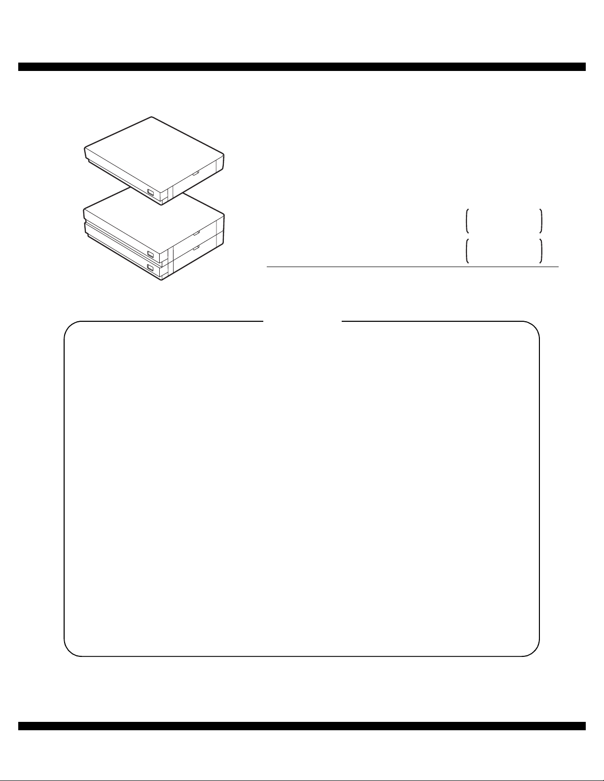
SERVICE MANUAL
Digital copier
MODEL
CONTENTS
CODE : 00Z
ARD22//A1E
: Paper feed unit
1-Stage paper
AR-D21
AR-D22
feed unit
2-Stage paper
feed unit
[1] GENERAL. . . . . . . . . . . . . . . . . . . . . . . . . . . . . . . . . . . . . . . . . . . 1
[2] SPECIFICATIONS . . . . . . . . . . . . . . . . . . . . . . . . . . . . . . . . . . . . 1
[3] UNPACKING AND INSTALLATION . . . . . . . . . . . . . . . . . . . . . . . 1
[4] EXTERNAL VIEW AND INTERNAL STRUCTURE . . . . . . . . . . . 6
[5] OPERATION DESCRIPTION. . . . . . . . . . . . . . . . . . . . . . . . . . . . 7
[6] DISASSEMBLY AND ASSEMBLY . . . . . . . . . . . . . . . . . . . . . . . . 7
[7] MAINTENANCE . . . . . . . . . . . . . . . . . . . . . . . . . . . . . . . . . . . . . . 9
[8] ELECTRICAL SECTION. . . . . . . . . . . . . . . . . . . . . . . . . . . . . . . 10
Parts mark ed w ith "!" are important for maintaining the safety of the set. Be sure to replace these parts with specified
ones for maintaining the safety and performance of the set.
This document has been pub lished to be used
SHARP CORPORATION
for after sales service only.
The contents are subject to change without notice.
Page 2

Page 3
[1] GENERAL
The AR-D21 (1-stage paper feed unit) and the AR-D22 (2-stage paper
feed unit) are optional paper feed units added to the digital copier, and
their cassettes are common with those of the main machine.
[2] SPECIFICATIONS
1. Paper feed unit (AR-D21/AR-D22)
AR-D21 AR-D22
No. of stage 1-stage 2-stage
Capacity 550 pages x 1 stage
Size detection No (The paper size is set with the user program.)
Paper empty
detection
Paper feed
size
Size when
shipping
Size selection User selection (Set by the user program.)
Cassette
installation
Heater Provided only for Japan.
Power source Supplied from the copier. DC24V.
Power
consumption
Drive supply
External
dimensions
Weight About 6.1kg About 11.8kg
(Japan)
500 pages x 1 stage
(EX)
(Note) Japan: 64g/m
Provided
A3, B4, A4, A4R, B5, B5R, 16k, 16kR, 8k,
11 x 17, 8.5 x 14, 8.5 x 13, 8.5 x 11, 8.5 x 11R
AB series: A4
Inch series: 8.5 x 11
A3, B4, A4, A4R, B5, B5R, 11 x 17, 8.5 x 14, 8.5 x 13,
8.5 x 11, 8.5 x 11R
Installed by the user.
5.6W 8.4W
• When installed as the
2-stage cassette fo r the
2-stage cassette standard
model: Supplied via gears
from the copier.
• When installed as the
optional 2-stage or 3stage cassette:
Sup plied by the
individu al m otor.
596(W) x 498(D) x
97(H) mm
550 pages x 2 stages
(Total 1,100pages)
(Japan)
500 pages x 2 stages
(Total 1,000 pages)
(EX)
2
, EX: 80g/m
Supplied by the
individual motor.
596(W) x 498(D) x
194(H)mm
2
[3] UNPACKING AND INSTALLATION
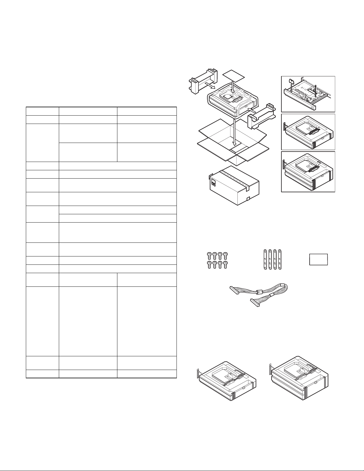
1. Unpacking
AR-D21
AR-D22
2. Installation
PARTS INCLUDED
Fixing plates: 4 pcs. Paper size labelScrews (M4 x 12): 8 pcs.
Cassette relay harness
(contained in the optional paper feed unit)
Remove all pieces of fixing tape and fixing materials from the paper
feed unit.
AR-D21/D22 GENERAL
– 1 –
Page 4
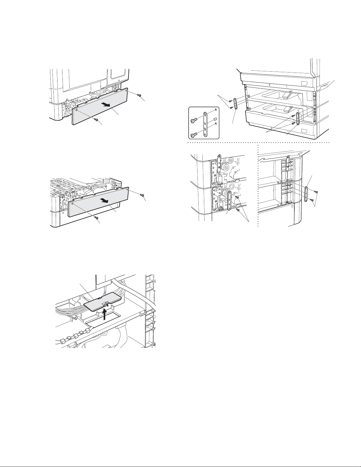
Turn off the main switch of the copier and then remove the power
plug of the copier from the outlet.
1. Remove the rear cover from the copier.
Remove the two screws and then remove the rear cover from the
copier.
Screw
Rear cover
Screw
2. Remove the rear cover from the optional paper feed unit.
Remove the two screws and then remove the rear cover from the
optional paper feed unit.
4. Attach the copier
Place the copier on the optional paper feed unit and remove the second
and third paper trays.
Connect the copier to the paper feed unit using four fixing plates and
two screws (M4 x 12) for each plate.
Front side
Screws (M4 x 12)
Detailed view
Fixing plate
Screws (M4 x 12)
Left of rear side
Fixing plate
Right of rear side
Fixing plate
Screw
3. Remove the connector cover.
Remove the cover from the connector.
Connector cover
Rear cover
Screw
Fixing plate
Screws
(M4 x 12)
Screws
(M4 x 12)
AR-D21/D22 UNPACKING AND INSTALLATION
– 2 –
Page 5
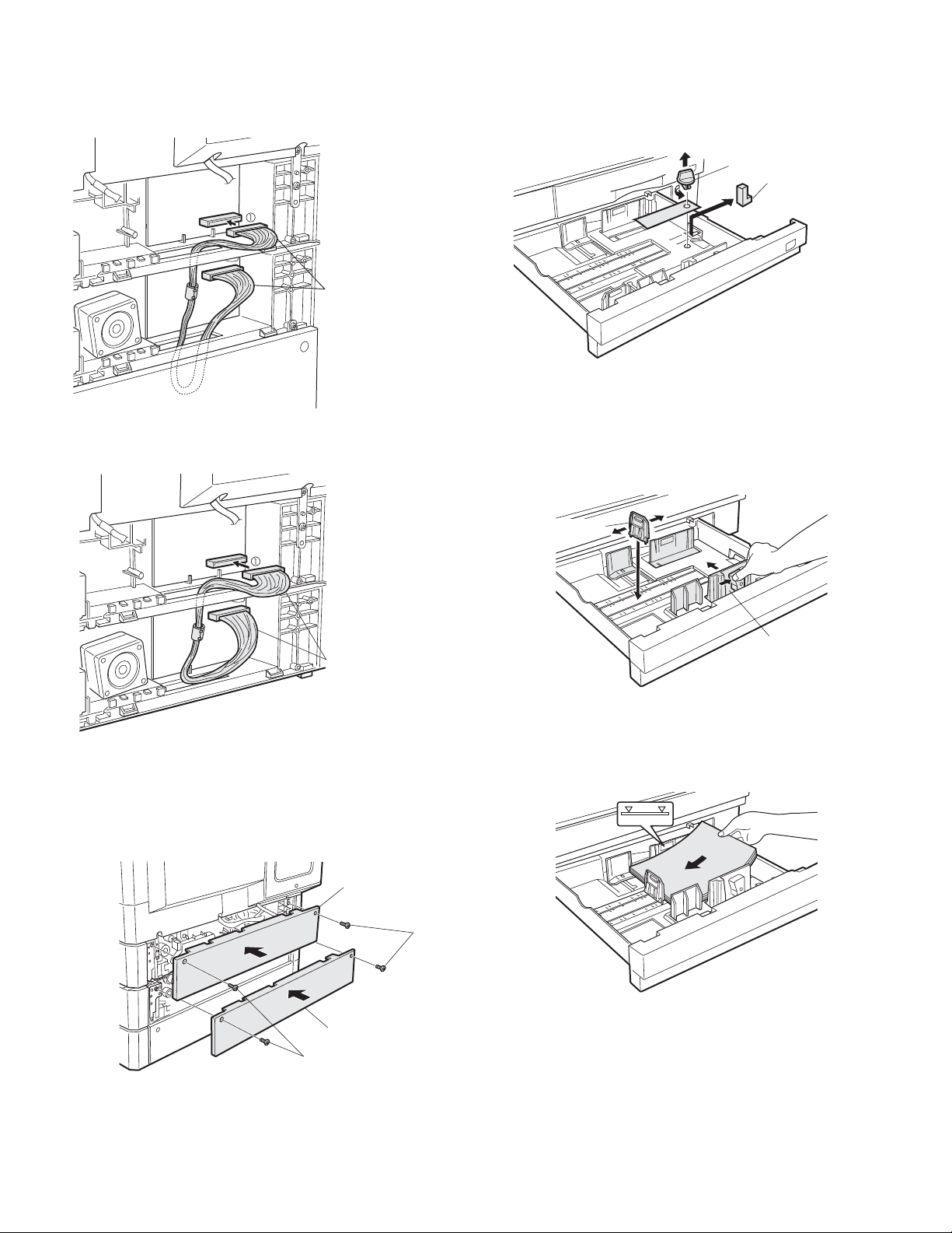
5. Connect the harness.
Connect the cassette interface harness contained in the opt ional paper
feed unit to the paper feed unit interface PWB.
• For two tray type
Cassette relay harness
• For one tray type
7. Remove the securing fixture for packing the paper feed
unit and remove the packing material.
Remove the securing fixture for packing that fixes the paper pressure
plate of the tray by rotating it in the direction of the arr ow and remove
the packing material.
Securing fixture for packing
Packing material
Caution: Be sure to remove the securing fixture bofore turning on the
power.
8. Change the paper size in the tray.
Hold the grip and slide the cassette side plate to adjust it to the paper to
be used.
Then, fit the rear end plate to the specified size position.
Cassette relay harness
6. Attach the rear covers of the copier and the optional
paper feed unit.
Attach the rear covers of the copier and the optional paper feed unit
using two screws respectively.
Rear cover
Screws
Rear plate
Side plate
Insert the power plug of the copier to the outlet and turn on the
main switch of the copier. Then, ca r r y out the followi ng procedure.
9. Load paper into the paper tray.
Do not exceed the maximum height line.
Real cover
Screws
10.Check for center displacement.
• Set an original on the document glass and copy it using the paper
tray in the copier.
Then, copy an original using the attached optional paper feed unit.
• If the center of the copy image from the tray in t he copier is different
from that of the copy image from the optional paper feed unit, carry
out adjustment referring to the service manual.
Installation of Pa per feed unit is now complet e.
AR-D21/D22 UNPACKING AND INSTALLATION
– 3 –
Page 6

Page 7
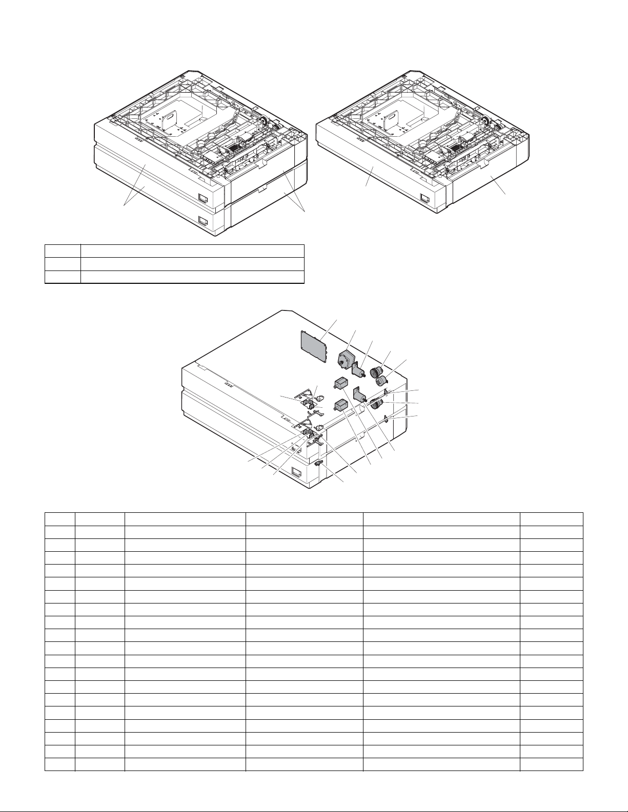
[4] EXTERNAL VIEW AND INTERNAL STRUCTURE
1. External view
1
No. Name
1 Paper feed tray
2 Paper feed right cover
AR-D22
1
2
AR-D21
2
2. Internal strec t ure
1
2
3
4
5
13
12
14
10
18
9
15
16
17
11
Moter and sensor solenoid etc.
No. Code Name Type Function/Operation Remark
1PWBInterface PWB
2 DM Drive motor Hybrid Drive s gears.
3 LUM3 Lift-up motor (No. 1 tray)
4 CPFS3 Paper feed clutch Electromagnetic clutch Rotates the paper feed roller.
5 TRC3 Transport clutch Electromagnetic clutch Rotates the transport roller.
6 CD3 Cassette detection SW Contact Detects cassette empty.
7 CD4 Cassette detection SW Contact Detects cassette empty. AR-D22 only
8 LUM4 Lift-up motor (No. 2 tray)
9 CPFC3 Paper feed solenoid DC solenoid Feeds paper.
10 DSWR3 Door open/close detection SW Contact Detects door open/close.
11 DSWR4 Door open/close detection SW Contact Detects door open/close. AR-D22 only
12 PED3 Paper empty sensor Photo transmission Detects paper empty in the cassette.
13 LUD3 Upper limit sensor Photo transmission Detects the upper limit for paper pickup.
14 PFD3 Paper entry sensor Photo transmission Detects paper transport.
15 PED4 Paper empty sensor Photo transmission Detects paper empty in the cassette. AR-D22 only
16 LUD4 Upper limit sensor Photo transmission Detects the upper limit for paper pickup. AR-D22 only
17 PFD4 Paper entry sensor Photo transmission Detects paper transport. AR-D22 only
18 CPFC4 Paper feed solenoid DC solenoid Feeds paper. AR-D22 only
19 CPFS4 Paper feed clutch Electromagnetic clutch Rotates the paper feed roller AR-D22 only
6
19
7
8
AR-D21/D22 EXTERNAL VIEW AND INTERNAL STRUCTURE
– 4 –
Page 8

Page 9
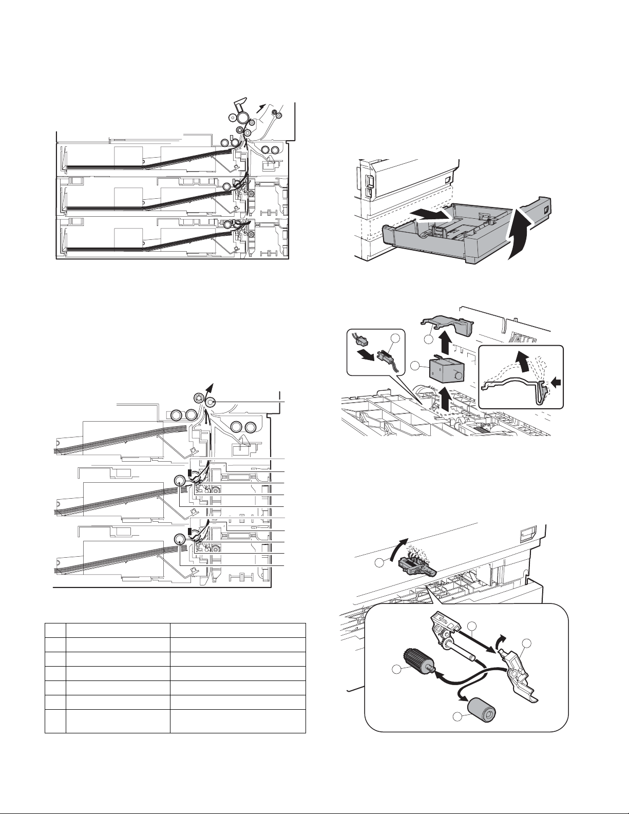
[5] OPERATION DESCRIPTION
1. Paper transport path
2. Operation descriptio ns
The operations of this unit is controlled by the copier, and the pickup
roller, the paper feed roller, etc. are driven by the drive motor. Paper
picked up by the pickup roller is transported by the paper feed roller,
detected by the paper entry sensor, and fed to the resist roller.
[6] DISASSEMBLY AND ASSEMBLY
For disassembly, follow instructions of illustrations 1, 2, 3, ... in this
sequence. For assembly, reverse the disassembly procedures.
For replacement of parts described in this manual, refer to the Pa rts
Guide.
1. Paper feed solenoid
1 - 1
1 - 2
2
1
3
No. Part name Operation
1 Pickup roller Picks up paper.
2 Paper feed roller Transports paper.
3 Separation sheet Press paper t o t h e p a p e r f e e d r oller.
4 Paper entry detection ACT Detects transport of paper.
5 Paper entry sensor Detects transport of paper.
6 Resist roller Synchronizes the p aper lea d edge
and the image lead edge.
6
5
4
2. Paper feed roller
3
2
1
Refer to 1 - 1.
2 - 1
5
4
3
2
1
1
3
2
4
4
AR-D21/D22 OPERATION DESCRIPTION
– 5 –
Page 10
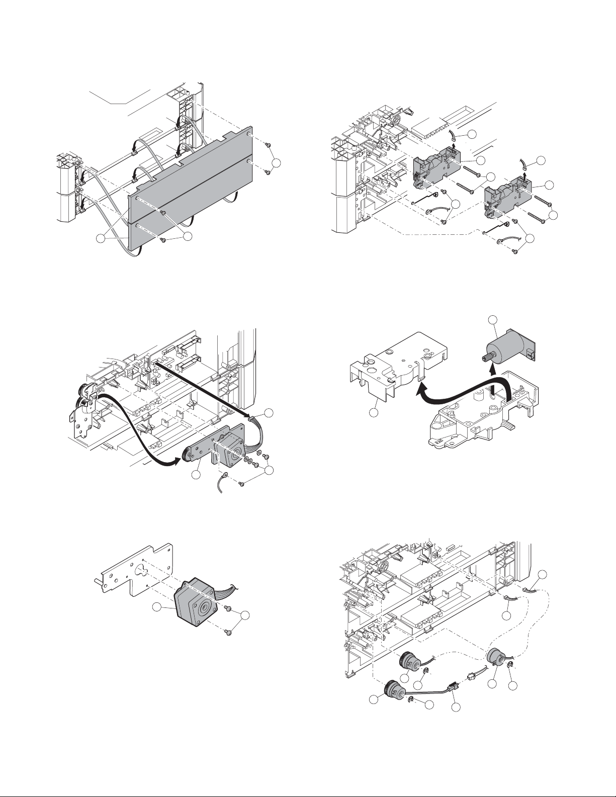
3. Motor, Clutch, Belt, Sensor PWB, Dehumidifier heater
3 - 1
2
A. Drive motor
3 - A - 1
B. Lift-up motor
3 - B - 1
1
1
1
3 - 5
3
2
2
2
1
3
2
2
3 - A - 2
1
3
2
1
C. Paper feed clutch, Transport clutch
3 - C - 1
1
2
1
3
2
3
2
1
1
3
2
AR-D21/D22 DI SASSEMBLY AND ASSEMBLY
– 6 –
Page 11
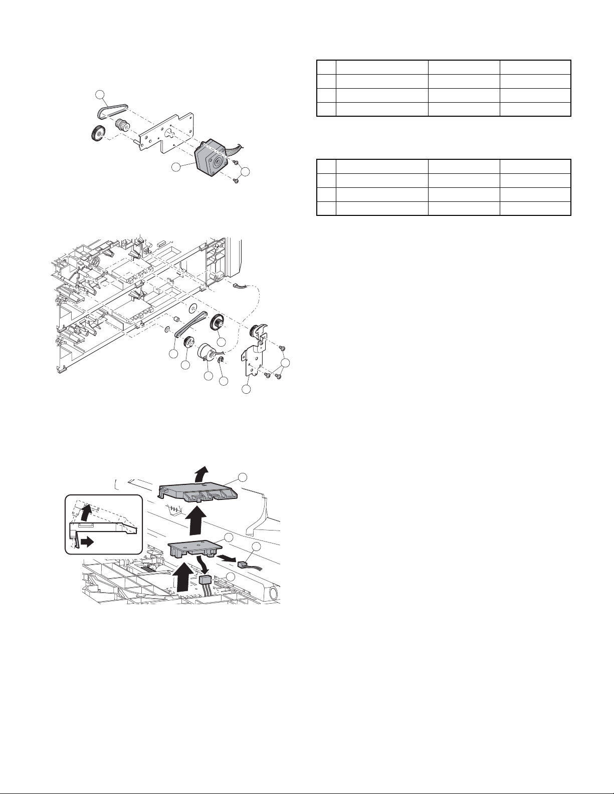
D. Belt
Refer to 3 - A - 1.
3 - D - 1
[7] MAINTENANCE
No. Name Work item When service call
1 Pickup roller Cleaning 50K
3
2 Paper feed roller Cleaning 50K
3 Separation sheet Cleaning 50K
For the replacement method of the pickup roller and paper feed roller,
refer to “[6] DISASSEMBLY AND AS SEMBLY”.
3 - D - 2
E. Sensor PWB
3 - E - 1
2
6
5
4
1
3
1
3
2
No. Name Work item When service call
1 Pickup rollor Replacement 100K
2 Paper feed roller Replacement 100K
3 Separation sheet Replacement 100K
1
2
3
3
AR-D21/D22 MAINTENANCE
– 7 –
Page 12

Page 13

D
D
D
D
[8] ELECTRICAL SECTION
12345678
12345678
12345678
12345678
1. BLOCK DIAGRAM
B
B
B
C
C
C
C
B
A
Copier
(MCU PWB)
CSSEL(A,B,C)
Y2
2
(PCL,PCS,LUM)
AI,BI,/AI,/BI
OPCASSEL
Y1B
1B
(PCL,PCS,
TRCL,LUM)
Y1A
1A(PCL,PCS,
TRCL,LUM)
DATA
SELECTOR
5V
DATA
SELECTOR
TRANSISTOR
ARRAY
24V
MOTOR
DRIVER
CASSETTE INTERFACE PWB
DATA
SELECTOR
PPD1B
PAP1B
LUD1B
DRS1B
CSS1B
24V
/PCL1B
/PCS1B
/TRCLB
LUM1BD
MOTOR
(A,/A,B,/B)
24V
PPD1B
PAP1B
LUD1B
5V
5V
5V
PPD2
PAP2
LUD2
DRS2
CSS2
/PCL2
/PCS2
LUM2D
24V
21
21
21
21
3
3
3
3
:MULTI CASSETTE LOWER
D
D
D
D
5V
DATA
SELECTOR
TRANSISTOR
ARRAY
24V
MOTOR
DRIVER
CASSETTE INTERFACE PWB
:OPTION 2nd CASSETTE or MULTI CASSETTE
B
B
B
C
C
C
C
AR-D21/D22 EL EC T R I C AL SECTION
– 8 –
B
DRS1B
CSS1B
24V
/PCL1B
/PCS1B
/TRCLB
LUM1BD
MOTOR
(A,/A,B,/B)
24V
5V
PPD2
PAP2
LUD2
DRS2
CSS2
/PCL2
/PCS2
LUM2D
24V
A A
A A
A A
A
87654
87654
87654
87654
Page 14

B
B
B
B
1
2
179228-2(AMP)
PHR-3
LB
GL
123
DRS
HPIN
SGND
B3B-PH-K-S
Sensor PWB
PAP1H:
LUD1H:Lift-up upper
limit sensor
PPD1H:Paper entry sensor
DRS:Door sensor
PPD
LUD
HPIN
PAP
+5V
SGND
1
26543
B6B-PH-K-S
GLORPKLBBR
BR
PHR-6
PHDR-14VS
GLORPKLBBRBRRDPLRD
PL
GL
3+5V
2PPD2
6
5DRS2
7
4PAP2
1SGND
PGND
LUD2
CSS2
CN4(B14B-PHDSS-B)
SMP-02V-NC(RD)(JST)
Paper feed
BR
BR
1
1
RD
BR
solenoid
2
2
Lift-up motor
321
GL
LB
PHR-3
SMR-02V-N(RD)(JST)
Cassette
detection
1
2
Paper feed
clutch
179228-2(AMP)
PL
GL
PL
PL
1
2
SMR-02V-B(JST)
1
2
RD
PL
SMP-02V-BC(JST)
GL
BR
LB
9108
14
13PGND
12
11
LUM2D
+24V
/PCL2
/PCS2
+24V
SMP-02V-NC(RD)(JST)
Paper feed
BR
BR
1
1
BR
RD
solenoid
2
2
SMR-02V-N(RD)(JST)
CN3(B3B-PH-K-S)
C
C
C
C
Paper feed
clutch
PHR-3
PLPLLB
1
N.C. 2
/PCL1A
3
+24V
HPR-3(BK)
1
TRCLA
CN2(B3B-PH-K-K(BK))
Lift-up motor
Cassette
detection
123
1
2
GL
GL
N.C. 2
3
PGND
179228-2(AMP)
PL
GL
PHR-3(BL)
PL
GL
3
1
N.C. 2
CSS1
SGND
CN7(B3B-PH-K-B(BL))
LB
PHR-3
PHR-3(RD)
LB
LB
1
3
N.C. 2
+24V
LUM1AD
CN1(B3B-PH-K-R(RD))
D
D
D
D
12345678
12345678
12345678
12345678
1
2
179228-2(AMP)
PHR-3
PL
GL
123
SRA-21T-4
PHR-5
1AI
CN6(B5B-PH-K-S)
2/AI
PULSE
3BI
MOTOR
FG
SRA-01T-3.2
524V1
4/BI
MULTI CASSETTE (UPPER)
Sensor PWB
PPD1H:Paper entry sensor
PPD
+5V
SGND
1
26543
B6B-PH-K-S
GLORPKLBBR
BR
PHR-6
PHR-8
GLBRORPKLB
1
CN8(B8B-PH-K-S)
DRS
HPIN
SGND
B3B-PH-K-S
LUD1H:Lift-up upper
limit sensor
HDRS:Door sensor
PAP1H:
LUD
PAP
DRS1
BR
BR
7
4
LUD1
/PCS1B
PAP13PPD1 26SGND5+5V
DRS1
RD
8+24V
A
21
21
21
21
MULTI CASSETTE (LOWER)
3
3
3
3
CASSETTE INTERFACE PWB
2nd CASSETTE
FG
SRA-01T-3.2
OPTION 2nd CASSETTE ONLY
SRA-21T-4
PLUSE
MOTOR
PHR-5
3BI
2/AI
524V1
4/BI
1AI
CN6(B5B-PH-K-S)
+24V
+24V
PGND
PGND
CASSETTE INTERFACE PWB
1A
2A
20B
19B
CN9(53314-1015)
GL
GL
GL
RD
RD
+24V
+24V
1A
20B
CN9(53314-1015)
RD
RD
SENSOR PWB
B6B-PH-K-S
CN8(B8B-PH-K-S)
SGND
SGND
SGND
18B
GL
GL
SGND
PGND
PGND
SGND
2A
18B
19B
GL
GL
GL
GL
PHR-3
B3B-PH-K-S
PPD1H:Paper entry sensor
PAP1H:
PPD
PAP
+5V
SGND
1
26543
GLORPKLBBR
BR
PHR-8 PHR-6
GLBRORPKLBBRBR
4
1
PAP13PPD1 26SGND5+5V
SGND
+5V3A+5V4A+3.3V
5A
6A
16B
17B
BL
GL
OR
OR
SGND
+5V3A+5V4A+3.3V
SGND
5A
16B
17B
GL
GL
OR
OR
1
2
179228-2(AMP)
PL
GL
123
DRS
HPIN
SGND
LUD1H:Lift-up upper
limit sensor
DRS:Door sensor
LUD
DRS1
RD
7
8+24V
LUD1
/PCS1A
DRS1
+3.3V
LUM2#
PGND
Y1A
8A
7A
15B
14B
BL
PK
GL
BR
BL
PL
6A
PCS2#
13B
+3.3V
15B
BL
SMP-02V-NC(RD)(JST)
Y1B
LB
LUM2#
PGND
7A
14B
PK
GL
Paper feed
solenoid
BR
BR
1
2
1
2
BR
RD
PCL2#
Y2
12B9A10A
PK
BR
Y1A
8A
BR
SMR-02V-N(RD)(JST)
LUM1B#
11B
PL
PCS2#
13B
LB
PL
PHR-3
PL
CN3(B3B-PH-K-S)
CSSELA#
11A
LB
PK
PCL2#
Y1B
12B9A10A
PK
Paper feed
clutch
1
N.C. 2
/PCL1A
TRCLB#
CSSELC#
10B
12A
BR
LUM1B#
Y2
CSSELA#
11A
11B
PL
LB
BR
HPR-3(BK)
PL
LB
1
3
TRCLA
+24V
CN2(B3B-PH-K-K(BK))
PCS1B#
PCL1B#
CSSELB#
9B
8B
13A
LB
PL
PK
PK
BR
TRCLB#
10B
BR
LB
N.C. 2
BI#
14A
PL
CSSELC#
PCS1B#
9B
12A
PL
3
+24V
CN1(B3B-PH-K-R(RD))
/BI#
AI#
7B
15A
LB
PCL1B#
CSSELB#
8B
13A
LB
PK
Lift-up motor
123
LB
PHR-3
PHR-3(RD)
LB
1
N.C. 2
LUM1AD
OPCASSEL#
/AI#
6B
16A
PK
BR
BI#
AI#
7B
14A
PL
BR
GL
GL
3
PGND
LUM1A#5B
+24V17A
PL
RD
/BI#
/AI#
LUM1A#5B
OPCASSEL#
6B
15A
16A
PL
LB
PK
BR
Cassette
detection
1
2
179228-2(AMP)
PL
GL
PHR-3(BL)
PL
GL
3
1
N.C. 2
CSS1
SGND
CN7(B3B-PH-K-B(BL))
TRCLA#4B
+24V18A
PCS1A#3B
PGND19A
LB
PK
GL
RD
+24V17A
RD
PCL1A#2B
BR
TRCLA#4B
LB
RD
CN5(53314-1015)
PGND20A
GL
GL
+24V18A
PCS1A#3B
PGND19A
GL
PK
51089-4005
1A
20B
+24V
+24V
SGND1B
BR
GLRDRD
PCL1A#2B
2A
PGND
GL
GL
PGND20A
19B
PGND
GL
GL
SGND1B
SGND
GL
18B
SGND
GL
SGND
GL
17B
SGND
ORORBL
5A
CN5(53314-1015)
6A
16B
+5V3A+5V4A+3.3V
MULTI CASSETTTE
PL
11B
N.C.
LB
11A
CSSELA#
PKBRBR
PL
9B
10B
12A
13A
N.C.
N.C.
CSSELC#
CSSELB#
1SGND
3+5V
2 PPD2
CN4(B14B-PHDSS-B)
PK
PLLBBR
PK
8B
N.C.
4 PAP2
14A
BI#
5 DRS2
7B
AI#
LUD2
6
LB
15A
/BI#
PGND
7
PKBRRDGLGL
PLRDBRGLLB
6B
16A
LUM1B# 5B
+24V 17A
TRCLB# 4B
+24V 18A
PCS1B# 3B
PGND 19A
PCL1B# 2B
PGND 20A
OPCASSEL#
/AI#
+24V
/PCL2
CSS2
+24V
9108
11
SGND 1B
LUM2D
/PCS2
14
13 PGND
12
2nd CASSETTTE
PK
PK
BL
GL
BR
LB
PL
8A
7A
15B
14B
13B
12B9A10A
PCS2#
+3.3V
LUM2#
PGND
Y1B
PCL2#
Y2
N.C.
2. Actual wiring diagram
MCU PWB
D
D
D
D
51089-4005
+24V
+24V
1A
20B
GLRDRD
PGND
2A
GL
PGND
19B
GL
SGND
GL
SGND
18B
GL
SGND
GL
SGND
17B
ORORBL
5A
+5V3A+5V4A+3.3V
6A
16B
PL
LUM1B#
11B
PKBRBR
LB
CSSELA#
11A
TRCLB#
10B
PL
CSSELC#
PCS1B#
9B
12A
PK
PCL1B#
CSSELB#
8B
13A
C
C
C
C
PLLBBR
LB
/BI#
/AI#
BI#
AI#
LUM1A#5B
+24V17A
OPCASSEL#
7B
6B
14A
15A
16A
SGND1B
TRCLA#4B
+24V18A
PCS1A#3B
PGND19A
PCL1A#2B
PGND20A
87654
87654
87654
87654
B
B
B
B
A A
A A
A A
A
PK
PK
BL
GL
BR
LB
PL
+3.3V
LUM2#
PGND
Y1B
Y1A
PCS2#
PCL2#
Y2
8A
7A
14B
13B
15B
12B9A10A
PK
PKBRRDGLGL
PLRDBRGLLB
AR-D21/D22 EL EC T R I C AL SECTION
– 9 –
Page 15

B
B
B
D
D
D
D
12345678
12345678
12345678
12345678
C
C
C
C
CSS1
PPD1
DRS1
PAP1
LUD1
10Kx7
R37
3.3V
R41 R40R42R43
R39 R38
JP2 JP1
B
PPD2
PAP2
CSS2
DRS2
LUD2
2200pF/50Vx5
C35
C38 C37C39C40
JP1 MOTOR L MOTOR
JP2 1, 2 Cassette L 1 Step
10Kx5
3.3V
R15R13 R1 2
R14 R16
C9C12
C13
C11
C10
A
Multi Cassette Only
(QS53)
21
21
21
2200pF/50Vx6
21
Option Cassette Only
(QS52,QS53)
R23
R31
C31
24V
7.5K
C22
2200pF/
7.5K
2200pF/50V
(2-1A)
AIBI24V1
/BI
/AI
F2
ICP-N38
47uF/35V
C1
+
0.047uF/50V
C18
0.047uF/50V
C19
8
20
10
18
1
NC17NC16NC15NC14NC12NC
Vmm
OUT A
OUT B
OUT /A
OUT /B
CrA2CrB26VsA4RsA9VrefA3VrefB25RsB19VsB24In /A5In A6In /B23In B
IC2
R20
1K
50V
C20
3300pF/50V
C33
0.1uF/25V
R3 1.5(1W)
R4 1.5(1W)
R33 2.4k
R36 2.4k
R32
1.5kF
27
11
PG7PG13PG21LG
MTD1361
22
R22
1K
C21
3300pF/50V
C34
0.1uF/25V
R34
430F
AI#
BI#
/AI#
/BI#
C36
0.1uF/25V
PCL1A#
R30 1.5K
IC1
COM
9
24V
D04D13D22D31D415D514D613D7
IC5
VCC
W6Y
5
16
Y1A
PCL2#
LUM1A#
TRCLA#
PCS1A#
PCS2#
R25 1.5K
R27 1.5K
R29 1.5K
R28 1.5K
R26 1.5K
I11I22I33I44I55I66I7
O116O215O314O413O512O611O7
12
7
G
74HC151AF
GND
A11B10C
8
9
1Kx3
R17
R18
R19
CSSELB#
CSSELA#
LUM2#
R24 1.5K
7
8
GND
TD62001
10
C7
0.047uF/50V
C8
CSSELC#
0.047uF/
UDZS3.9B
ZD2
UDZS3.9B
ZD3
UDZS3.9B
ZD1
50V
C26
0.1uF/25V
IC4
16
D04D13D22D31D415D514D613D7
VCC
W6Y
5
Y2
12
A11B10C
7
G
74HC151AF
GND
8
9
C24
C25 C23
3
3
3
3
1000pF/50Vx3
C32
0.1uF/25V
R11
R35
1
VOUT
IC3
KIA78S05P
VIN
3
R5
3. Interface PWB circuit diagram (1/2)
24V
D
D
D
D
C5
10uF/16V
GND
2
C6
10uF/35V
R6
3.6K 1/4W
3.6K 1/4W
2.4KF
Q5
DTC143ZKA
47k
4.7k
OPCASSEL#
C
C
C
C
24V
/PCL2
/PCS2
/PCL1A
/TRCLA
/PCS1A
10k
R2
1.5k(1/2W)
F3
ICP-N38
5
6
3
Q4
IMZ4
LUM1AD
Q3
2
DTC114EKA
1 3
R10
1.5k
2
R21
47
4 1
24V
Multi Cassette Only
B
B
B
B
(QS53)
R7
10k
R1
1.5k(1/2W)
F1
ICP-N38
5
6
Q2
IMZ4
LUM2D
2
Q1
DTC114EKA
1 3
R8
1.5k
2
R9
47
4 1
3
87654
87654
87654
87654
A A
A A
A A
A
AR-D21/D22 EL EC T R I C AL SECTION
– 10 –
Page 16

B
B
B
PCS2#
PCL2#
B
AI#
LUM1B#
/AI#
3133353739
PCS1B#
TRCLB#
PCL1B#
40
B40B-PADKS-1
7
3
•¢
•¢
C17
0.1uF/25V
C16
0.1uF/25V
Option Cassette Only
(QS51,QS52)
D
D
D
D
12345678
12345678
12345678
12345678
123
CN7
CN1
B3B-PH-K-E(BL)
123
LUM1AD/TRCLA
B3B-PH-K-R(RD)
C
C
C
C
LUM2#
3.3V
5V
246
8
101214161820222426283032363438
CN5
1357911131517192123252729
4
•¢
A
NOTE
QS51:STANDARD 2ND CASSETTE
QS52:OPTION 2ND CASSETTE
QS53:OPTION MULTI CASSETTE
21
21
21
21
3
3
3
3
CN3
24V
5V 3.3V
CN9
123
/PCL1A CSS1
246
8
101214161820222426283032363438
1357911131517192123252729
B3B-PH-K-S
LUM2#
PCS2#
PCL2#
CN2
LUM1B#
TRCLB#
123
PCL1B#
PCS1B#
AI#
B3B-PH-K-K(BK)
/AI#
TRCLA#
PCS1A#
PCL1A#
3133353739
40
7
C29
B40B-PADSS-1
•¢3•¢
C30
0.1uF/25V
+
C3
0.1uF/25V
+
C4
10uF/16V
10uF/16V
C15
0.047uF/50V
24V
Y2
BI#
LUD2
CSSELA#
CSS2
/PCL2
8
101214
CSSELB#
CSSELC#
/PCS2
LUM2D
/BI#
OPCASSEL#
B14B-PHDSS-B
Y1B
PPD2
PAP2
Multi Cassette Only
(QS53)
246
135791113
CN4
5V
C14
0.047uF/50V
12345
CN6
Option Cassette Only
(QS52,QS53)
AI
BI
/AI
/BI
1234567
CN8
5V
24V1
8
B5B-PH-K-S
B8B-PH-K-S
24V
C2
47uF/35V
+
F4
ICP-N50
24V
BI#
CSSELB#
CSSELA#
CSSELC#
/BI#
OPCASSEL# LUM1A#
3. Interface PWB circuit diagram (2/2)
D
D
D
D
Y1AY2Y1B
C27
C
C
C
C
C28
0.047uF/50V
0.047uF/50V
DRS2
B
B
B
B
PPD1
PAP1
24V
LUD1
DRS1
/PCS1A
A A
A A
A A
A
87654
87654
87654
87654
AR-D21/D22 EL EC T R I C AL SECTION
– 11 –
Page 17

B
B
B
D
D
D
D
12345678
12345678
12345678
12345678
C
C
C
C
12345
PPD
PAP
DRS
LUD
6
S6B-PH-K-S
C3
102pF
CN1
5V
B
123
CN2
S3B-PH-K-S
DRS
A
21
21
21
21
3
3
3
3
PT3
GP1S58V
R3
220J/ 1/4W
Upper limit
C2
102pF
PT2
GP1S58V
R2
220J/ 1/4W
C1
102pF
PT1
GP1S58V
R1
5V
220J/ 1/4W
4. Sensor PWB circuit diagram
D
D
D
D
C
C
C
C
AR-D21/D22 EL EC T R I C AL SECTION
– 12 –
87654
87654
87654
87654
B
B
B
B
A A
A A
A A
A
Page 18

5. Parts layout
1) Cassette interface PWB
a. Parts surface
CN3 (B3B-PH-K-S)
3 +24V
2 N.C.
1 /PCL1A
CN4 (B14B-PHDSS-B)
13 PGND
11 +24V
9 +24V
7 PGND
5 DRS2
3 +5V
1 SGND
14 LUM2D
12 /PCS2
10 /PCL2
8 CSS2
6 LUD2
4 PAP2
2 PPD2
CN2 (B3B-PH-K BL)
3 +24V
2 N.C.
1 TRCLA
CN1 (B3B-PH-K-R RD)
3 PGND
2 N.C.
1 LUM1AD
CN6 (B5B-PH-K-S)
5 24V1
4 /B1
3 B1
2 /A1
1 A1
CN7 (B3B-PH-K BL)
3 SGND
2 N.C.
1 CSS1
CN8 (B8B-PH-K-S)
8 +24V
7 /PCS1B
6 LUD1
5 DRS1
4 PAP1
3 +5V
2 PPD1
1 SGND
CN5 (53314-1015) CN9 (53314-1015)
2 +24V
4 PGND
6 SGND
8 SGND
10 +5V
12 +3.3V
14 LUM2#
16 PCS2#
18 PCL#
20 N.C.
22 N.C.
24 N.C.
26 N.C.
28 A1#
30 /A1#
32 LUM1B#
34 TRCLB#
36 PCS1B#
38 PCL1B#
40 SGND
AR-D21/D22 EL EC T R I C AL SECTION
1 +24V
3 PGND
5 SGND
7 SGND
9 +5V
11 +3.3V
13 PGND
15 Y1B
17 N.C.
19 Y2
21 CSSELA#
23 CSSELC#
25 CSSELB#
27 B1#
29 /B1#
31 OPCASSEL#
33 +24V
35 +24V
37 PGND
39 PGND
2 +24V
4 PGND
6 SGND
8 SGND
10 +5V
12 +3.3V
14 LUM2#
16 PCS2#
18 PCL2#
20 LUM1B#
22 TRCLB#
24 PCS1B#
26 PCL1B#
28 A1#
30 /A1#
32 LUM1A#
34 TRCAL#
36 PCS1A#
38 PCL1A#
40 SGND
– 13 –
1 +24V
3 PGND
5 SGND
7 SGND
9 +5V
11 +3.3V
13 PGND
15 Y1A
17 Y1B
19 Y2
21 CSSELA#
23 CSSELC#
25 CSSELB#
27 B1#
29 /B1#
31 OPCASSEL#
33 +24V
35 +24V
37 PGND
39 PGND
Page 19

b. Solder surface
2) Cassette sensor PWB
a. Parts surface b. Solder surface
CN1 (S6B-PH-K-S)
6 LUD
5 DRS
4 PAP
3 5V
2 PPD
1 SGND
3 DRS
2 N.C.
1 SGND
AR-D21/D22 EL EC T R I C AL SECTION
– 14 –
Page 20

Page 21

q
PARTS GUIDE
CODE:00ZARD22//P1/
デジタル複合機
デジタル複合機
デジタル複合機デジタル複合機
給紙ユニット
給紙ユニット
給紙ユニット給紙ユニット
[AR-D21]
[AR-D22]
1
外装部 (Exteriors)
2
搬送部 (Paper transfer section)
3
給紙部 (Paper feed section)
DIGITAL COPIER
Paper feed unit
AR-D21
MODEL
このパーツガイドに掲載されている表示価格ランクは消費税抜きです。
CONTENTS
AR-D22
4
駆動部 (Drive section)
5
リフトアップユニット (Lift up unit)
6
550 枚カセット (550 sheets cassette unit)
7
梱包&付属品 (Packing material & Accessories)
8
カセット中継基板 (Cassette interface PWB)
■
本書はサービス活動用に作成した資料です。
一部内容が製品の改良・改善等により予告
なしに変わることがあります。
索引 (Index)
SHARP CORPORATION
This document has been published to be used for
after sales service only.
The contents are subject to change without notice.
Page 22

Page 23

補修部品のランク付
市場における補修部品の在庫管理が、適正に運営出来る手助けとなることを、目的とします。
Aランク : メンテナンスパーツ、メンテナンスパーツには入っていないがメンテナンスパーツに近い消耗パーツ。
Bランク : 性能・機能パーツ(センサー、クラッチ等の電気パーツ)、消耗パーツ。
Eランク : 基板含むユニットパーツ。
Dランク : 整備パーツ(外装、パッキング、同梱パーツ)。
Cランク : 上記ランク以外のパーツ(基板の子部品を除いたもの)。
DEFINITION
Rank A : Maintenance parts, and consumable parts which are not included in but closely related to maintenance parts
Rank B : Performance/function parts (sensors, clutches, and other electrical parts), consumable parts
Rank E : Unit parts including PWB
Rank D : Preparation parts (External fitting, packing, parts packed together)
Rank C : Parts other than the above (excluding sub components of PWB)
安全性・信頼性確保のため部品は、必ず正規のものをご使用下さい。
! 印の商品は、安全上重要な部品です。交換をする時は、安全及び性能維持のため必ず指定の部品をご使用下さい。
Because parts marked with "!" is indispensable for the machine safety maintenance and operation, it must be replaced with
the parts specific to the product specification.
F
当モデルのサービス資料には、この資料以外にサービスマニュアル ( 回路図含む ) があります。合わせてご利用下さい。
F Other than this Parts Guide, please refer to documents Service Manual (including Circuit Diagram)of this model.
F Please use the 13 digit code described in the right hand corner of front cover of the document, when you place an order.
F For U.S. only-Use order codes provided in advertising literature. Do not order from parts department.
– 1 –
Page 24

1
外装部 (Exteriors)
NO. PARTS CODE
1 GCAB-0030QSZA AN EG N D
2 XEBSE40P12000 AA DD C
3 LPLTM0240QSZZ AC DJ C
5 GCOVA0025QSZB AS EQ N D
7 LFRM-0039QSZB BK HG N C
8 LPLTM0236QSZZ AG DX C
10 PCOVP0063QSZB AD DJ N C
12 NSFTZ0048QSZZ AG DX C
13 NKOM-0005QSZZ AC DJ C
14 XBPSD30P08KS0 AA DD C
15 GLEGG0064FCZZ AC DJ C
16 LPLTM0237QSZZ AH DX C
17 RHET-0006QSZZ AQ EQ B
18 LPLTP0192QSZZ AK DX C
19 XEBSD30P08000 AA DD C
20 DHAI-0393QSZZ AK EB N C
22 PSHEZ0325QSZZ AB DJ C
23 LX-BZ0037QSZZ AB DD C
24 PSHEZ0278QSZZ AE DJ C
25 MSPRD0277QSZZ AN EG C
26 TLABS4306FCZZ AC DJ D
1
外装部 (Exteriors)
PRICE RANK
Ex. Ja.
MARK
NEW
PART
RANK
Left cabinet 左キャビネット
Screw(4×12) ビス
Joint plate 連結板
Rear cover 後カバー
Frame フレーム
Reinforce plate R 補強板 R
Front cover 前カバー
Cassette collar shaft カセットコロ軸
Cassette guide collar カセットガイドコロ
Screw(3×8KS) ビス
Rubber foot ゴム足
Reinforce plate F 補強板 F
Cassette dry heater [Japan only] カセット除湿ヒータ
Dry heater fixing plate [Japan only] カセット除湿ヒータ取付板
Screw(3×8) [Japan only] ビス
Dry heater harness [Japan only] 除湿ヒータ分岐ハーネス
Frame lower mylar フレーム下マイラー
Screw(4×12) ビス
Heat insulation sheet 多段断熱シート
2nd joint earth spring [Taiwan] 2nd 連結アーススプリング
Noise label A [U.S.A,Canada] ノイズラベル A
DESCRIPTION
2
2
25
2
26
1
2
3
2
2
5
2
23
14
3
19
13
19
12
15
16
23
20
24
22
3
2
7
15
17
18
19
2
10
8
3
2
FCP06676
2
– 2 –
Page 25

2
搬送部 (Paper transfer section)
NO. PARTS CODE
1 MSPRC0141QSZZ AB DJ C
2 MLOKZ0001QSZZ AC DJ C
3 XEPSD30P08X00 AA DD C
4 PGIDM0068QSZZ AP EQ C
5 MARMP0015QSZZ AD DJ C
6 NSFTZ0054QSZZ AE DJ C
7 NROLP1060FCZZ AF DS C
MSPRP0345QSZZ AD DJ N C
8
MSPRP0273QSZZ AD DJ C
9 XEBSD30P08000 AA DD C
10 GCOVA0026QSZB AP EQ N D
11 XEBSD30P10000 AA DD C
12 PCOVP0089QSZZ AD DJ C
13 LPLTP0297QSZZ AC DJ C
14 PSHEZ0378QSZZ AG DX C
15 NROLR0052QSZZ AN EQ C
16 MSPRC0270QSZZ AB DJ C
17 NBRGZ0503FCZZ AC DJ C
18 LSTPP0011QSZZ AC DJ C
19 LRALP0009QSZZ AQ EQ C
20 XBPSD30P08KS0 AA DD C
21 NKOM-0005QSZZ AC DJ C
22 NSFTZ0048QSZZ AG DX C
23 PGIDM0074QSZZ AK DX C
24 XEBSE40P12000 AA DD C
25 MSPRD0259QSZZ AC DJ C
26 MSPRD0287QSZZ AC DJ C
27 NSFTZ0064QSZZ AD DJ C
28 NROLP0087QSZZ AD DJ C
29 PSHEZ0301QSZZ AC DJ C
30 PSHEZ0302QSZZ AC DJ C
501 CCOVP0089RS51 AQ EQ E
502 CGIDM0068RS51 AS EQ E
PRICE RANK
Ex. Ja.
NEW
MARK
PART
RANK
Lock spring ロックスプリング
Paper guide lock ペーパーガイドロック
Screw(3×8X) ビス
Transport paper guide 搬送ペーパーガイド
Door arm ドアアーム
Transport paper guide shaft 搬送ペーパーガイドシャフト
U-turn roller U ターンローラー
Transport paper guide spring [AR-D21] 搬送ペーパーガイドスプリング
Transport paper guide spring [AR-D22] 搬送ペーパーガイドスプリング
Screw(3×8) ビス
Right cover 右カバー
Screw(3×10) ビス
Plate cover プレートカバー
Separation plate 捌きプレート
Separation sheet 捌きシート
Transport roller 搬送ローラー
Separation plate spring 捌きプレートスプリング
Bearing(B-F5-13) 軸受
E-ring E- リング
Cassette rail R カセットレール R
Screw(3×8KS) ビス
Cassette guide collar カセットガイドコロ
Cassette collar shaft カセットコロ軸
U-turn guide U ターンガイド
Screw(4×12) ビス
U turn guide spring [AR-D22] 多段 U ターンガイドスプリング
Paper feed assistance roller SP 給紙補助ローラースプリング
Paper feed assistance roller shaft 給紙補助ローラー軸
Paper feed assistance roller 給紙補助ローラー
Rail R side mylar F レール R サイドマイラー F
Rail R side mylar R レール R サイドマイラー R
Plate cover unit プレートカバーユニット
Transport paper guide unit [AR-D21] 搬送ペーパーガイドユニット
DESCRIPTION
2
搬送部 (Paper transfer section)
23
e
30
29
22
14
13
26
21
24
15
17
18
20
24
23
f
30
29
19
14
13
26
22
21
20
24
24
19
28
501
28
501
27
26
16
12
27
26
16
12
25
1
11
3
3
1
2
2
1
502
4
a
8
9
6
b
10
c
d
10
FCP06677
11
a
b
7
e
3
11
2
f
1
2
c
5
d
4
5
– 3 –
Page 26

3
給紙部 (Paper feed section)
NO. PARTS CODE
1 CPWBF0082QSE3 BE GN E
2 PCOVP0070QSZZ AD DJ C
3 XEBSD30P10000 AA DD C
5 MLEVP0063QSZZ AD DJ C
6 MLEVP0064QSZZ AD DJ C
7 MLEVP0062QSZZ AC DJ C
8 PCOVP0064QSZZ AD DJ C
9 RPLU-0026QSZ1 AR EQ B
10 MARMP0026QSZZ AD DJ C
11 MSPRC0209QSZ1 AC DJ C
13 NSFTZ0050QSZ1 AH DX C
14 QSW-B0017QSZZ AF DS B
17 DHAI-0397QSZZ AD DJ N C
18 NBRGC0100FCZ1 AC DJ C
19 MSPRD0206QSZZ AC DJ C
20 MARMP0021QSZZ AD DJ C
21 NGERH0107QSZZ AD DJ C
22 LPIN-0026MCZZ AA DD C
23 NROLR0055QSZ1 AR EQ C
24 MARMP0019QSZZ AD DJ C
25 LSTPP0011QSZZ AC DJ C
26 NGERH0990FCZZ AB DJ C
27 NROLR0054QSZZ AP EQ C
29 DHAI-0394QSZZ AD DJ N C
30 MSPRD0204QSZZ AC DJ C
31 DHAI-0395QSZZ AG DX N C
PRICE RANK
Ex. Ja.
NEW
MARK
PART
RANK
Cassette interface PWB [AR-D22] 多段カセット中継基板
Sensor cover センサーカバー
Screw(3×10) ビス
Upper limit detect actuator 上限検知アクチュエーター
Paper detect actuator 紙検知アクチュエーター
P-IN detect actuator 入紙検知アクチュエーター
Solenoid cover ソレノイドカバー
Paper feed solenoid 給紙ソレノイド
Solenoid arm ソレノイドアーム
Solenoid spring ソレノイドスプリング
Paper feed roller shaft 給紙ローラ軸
Cassette detect switch カセット検知スイッチ
Cassette detect interface harness カセット検知中継ハーネス
Bearing 6 ベアリング 6
Pick up roller pressure spring ピックアップローラー加圧スプリング
Pick up arm R ピックアップアーム R
Paper feed gear 給紙ギヤ
Spring pin(φ2-10) スプリングピン
Paper feed roller 給紙ローラー
Pick up arm F ピックアップアーム F
E-ring E- リング
Gear(16T) ギヤ
Pick up roller ピックアップローラー
Door open/close detect harness ドア開閉検知ハーネス
P-IN detect actuator spring 入紙検知アクチュエータースプリング
Cassette sensor PWB harness カセットセンサー基板ハーネス
DESCRIPTION
3
給紙部 (Paper feed section)
1
a
2
8
14
17
3
10
4
9
11
5
13
a
7
31
30
6
19
14
24
27
26
21
18
20
22
29
25
23
FCP06678
– 4 –
Page 27

4
駆動部 (Drive section)
NO. PARTS CODE
1 PCOVP0084QSZZ AE DJ C
2 CPWBF0082QSE3 BE GN E
3 XEBSD30P08000 AA DD C
4 DHAI-0392QSZZ AU EZ N C
5 NBRGC0100FCZ1 AC DJ C
6 MARMP0018QSZZ AD DJ C
7 PCLC-0014QSZZ AS EQ B
8 XRESP40-06000 AA DD C
9 XRESP50-06000 AA DD C
10 MSPRT0203QSZZ AC DJ C
11 NGERH0119QSZZ AD DJ C
12 NGERH1207FCZZ AF DS C
13 CDAIU0024RS52 BA FX E
14 XEBSD40P30000 AA DD C
15 XEBSE40P12000 AA DD C
16 NGERH1207FCZZ AF DS C
17 DHAI-0396QSZZ AD DJ N C
20 LPLTM0203QSZ1 AF DS C
24 NGERH0121QSZZ AE DJ C
25 NBLTT0029QSZZ AG DX B
26 PCLC-0011QSZZ AS EQ B
28 NPLYZ0027QSZZ AD DJ C
29 PSHEZ0250QSZZ AB DJ C
30 NROLP0008QSZZ AD DJ C
31 PSHEZ0249QSZZ AB DJ C
32 NBRGC0529FCZZ AD DJ C
33 LPLTM0176QSZZ AH DX C
34 CFRM-0053QS02 AK DX C
35 NBLTT0025QSZZ AG DX C
36 NGERH0154QSZZ AD DJ C
37 NGERH1207FCZZ AF DS C
38 RMOTS0030QSZZ BA FX B
39 XHBSE30P08000 AA DD C
40 DHAI-0401QSZZ AC DJ N C
41 DHAI-0402QSZZ AL EB N C
42 XHBSE30P08000 AA DD C
43 CARMM0040QS02 AL EB C
44 PCLC-0015QSZZ AS EQ B
45 NGERH0022QSZZ AC DJ C
46 RCORF1036ACZZ AP EQ C
47 LX-BZ0322FCZZ AB DD C
48 XWHSD50-08120 AA DD C
49 LHLDZ0091QSZZ AD DJ C
50 LX-WZ5022BCZZ AA DD C
51 PSHEZ0276QSZZ AB DJ C
52 PSHEZ0277QSZZ AA DJ C
53 LX-BZ0342FCZZ AB DD C
501 CFRM-0053RS51 BC GJ E
PRICE RANK
Ex. Ja.
NEW
MARK
PART
RANK
Bottom cover 底カバー
Cassette interface PWB [AR-D22] 多段カセット中継基板
Screw(3×8) ビス
Cassette harness 2ND/ タダンハーネス
Bearing 6 ベアリング 6
Body joint arm [AR-D22] 本体連結アーム
Paper feed clutch(42T) 給紙クラッチ
E type ring E- リング
E type ring E- リング
Joint spring [AR-D22] 連結スプリング
Gear(36T) [AR-D22] ギヤ
Joint gear(40T) 連結ギヤ
Lift up unit リフトアップユニット
Screw(4×30) ビス
Screw(4×12) ビス
Joint gear(40T) [AR-D22] 連結ギヤ
Lift up harness リフトアップハーネス
Drive plate 多段駆動プレート
Gear(20T/45T/26P) ギヤ
Vertical delivery belt 縦搬送ベルト
Transport clutch 搬 送クラッチ
Vertical transport pulley 縦搬送プーリー
Flange mylar フランジマイラー
Pulley プーリー
Flange mylar フランジマイラー
Bearing 軸受
Clutch earth plate クラッチアース板
Motor frame モータ - フレーム
Drive belt 多段駆動ベルト
Gear(21T/28P) ギヤ
Gear(40T) ギヤ
Drive motor 駆動モータ -
Screw(3×8) ビス
Cassette earth harness カセットアースハーネス
Cassette harness [AR-D22] 4 段目カセットハーネス
Screw(3×8) ビス
Joint arm 多段連結アーム
Transport clutch [AR-D22] 搬送クラッチ
Gear(33T) ギヤ
Core コア
Screw ビス
Washer ワッシャ
Joint holder 多段連結ホルダー
Washer ワッシャ
Oscillating prevention sheet A 多段防振シート A
Oscillating prevention sheet B 多段防振シート B
Power supply SW stage screw 電源 SW 段ビス
Motor frame unit モーターフレームユニット
DESCRIPTION
5
リフトアップユニット (Lift up unit)
NO. PARTS CODE
1 CMOTV0778FCE2 AW FG E
2 NGERH0158QSZ1 AE DJ C
3 LDAIU0024QSZ1 AH DX C
4 NGERH0102QSZZ AD DJ C
5 NSFTZ0045QSZZ AC DJ C
6 NGERH0103QSZZ AE DJ C
7 NSFTZ0044QSZZ AC DJ C
8 NSFTZ0060QSZZ AC DJ C
9 NGERH0104QSZZ AE DJ C
10 NGERH0105QSZZ AD DJ C
11 PCOVP0061QSZ1 AH DX N C
12 MSPRD0251QSZZ AD DJ C
13 MSPRC0263QSZZ AC DJ C
(Unit)
901 CDAIU0024RS52 BA FX E
PRICE RANK
Ex. Ja.
NEW
MARK
PART
RANK
Lift up motor unit リフトアップモーターユニット
Gear(29T/11T) ギヤ
Lift up base リフトアップベース
Gear(53T/14T) ギヤ
Shaft シャフト
Gear(54T/13T) ギヤ
Shaft シャフト
Shaft シャフト
Gear(13T/42T) ギヤ
Gear(19T) ギヤ
Lift up cover リフトアップカバー
Cassette earth spring カセットアーススプリング
Lift up spring リフトアップスプリング
Lift up unit リフトアップユニット
DESCRIPTION
– 5 –
Page 28

4
駆動部 (Drive section)
45
11
3
4
2
3
46
e
d
41
a
b
33
5
リフトアップユニット (Lift up unit)
43
51
36
15
50
52
51
501
35
37
29
c
30
32
9
5
10
5
9
31
25
8
28
7
6
44
24
8
e
26
8
8
8
49
16
52
3
12
d
20
15
51
48
51
47
48
34
38
42
53
b
15
15
47
17
13
39
4
a
14
14
17
40
15
15
1
c
FCP06679
13
14
14
11
3
1
13
12
2
5
7
8
4
6
9
10
FCP06680
– 6 –
Page 29

6
550 枚カセット (550 sheets cassette unit)
NO. PARTS CODE
1 LPLTP0159QSZZ AD DJ C
2 LHLDW1226FCZZ AB DJ C
3 LPLTM0179QSZ1 AR EQ C
4 PSHEZ0274QSZZ AC DJ C
5 GCASP0005QSZ2 BA FX N D
6 PGIDM0070QSZ1 AM EG C
7 PTPE-0021QSZZ AD DJ C
8 LPLTM0181QSZ1 AB DJ C
9 PGIDM0071QSZZ AL EB C
10 LX-BZ0884FCZZ AB DD C
11 NGERH0193FCZZ AB DD C
12 MSPRC2631FCZZ AC DJ C
13 MLEVP0755FCZ1 AE DJ C
14 LX-BZ0833FCZZ AC DD C
15 CSHEZ0244QS02 AE DJ C
16 XRESP70-08000 AA DD C
17 NGERH0108QSZZ AD DJ C
18 MSPRC0210QSZZ AC DJ C
19 NSFTZ0047QSZZ AP EQ C
20 LPLTM0180QSZ1 AE DS C
21 NBRGP0041GCZZ AD DJ C
22 XEBSE40P10000 AA DD C
23 JHNDP0005QSZZ AY FQ N D
24 XBPSD40P08KS0 AA DD C
26 PCOVP0096QSZZ AN EQ N D
27 LPLTM0277QSZZ AC DJ C
(Unit)
901 CCASP0005RS55 BM HR N E
PRICE RANK
Ex. Ja.
NEW
MARK
PART
RANK
Cassette rear side plate カセット後端板
Turn fastener ターンファスナー
Rotation plate 回転板
Rotation plate sheet 回転板シート
550 sheets cassette 550 枚カセット
Guide F ガイド F
GID tape GID 両面テープ
Side plate guide 側板ガイド
Guide R ガイド R
Screw ビス
UC manual feed gear UC 手差しギヤ
Fusing pressure spring 定着加圧スプリング
Side plate F lever 側板 F レバー
Screw ビス
Cassette mylar カセットマイラー
E type ring E- リング
Lift gear(22T) リフトギヤ
Lift gear spring リフトギヤスプリング
Lift shaft リフトシャフト
Lift plate リフトプレート
Bearing 軸受
Screw(4×10) ビス
Cassette panel カセットパネル
Screw(4×8KS) ビス
Cassette panel line カセットパネルライン
Side plate guide R 側板ガイド R
550 sheets cassette unit 550 枚カセットユニット
DESCRIPTION
6
550 枚カセット (550 sheets cassette unit)
1
2
3
22
22
22
8
6
7
501
9
10
4
11
11
13
14
12
5
15
16
17
7
27
18
22
FCP06681
22
23
26
22
– 7 –
21
20
19
24
Page 30

7
梱包&付属品 (Packing material & Accessories)
NO. PARTS CODE
SSAKH3012KCZZ AD DJ D
3
SSAKH2002WCZZ AE DJ D
6 SPAKA0392QSZZ AD DJ D
7 LHLDW1226FCZZ AB DJ C
8 TCADZ1275FCZZ AB DJ D
9 TCADZ0288QSZZ AD DJ N D
10 SSAKA0231QCZZ AA DD D
TLABH0486QSZZ AE DS N D
11
TLABH0484QSZZ AE DS N D
7
梱包&付属品 (Packing material & Accessories)
4
PRICE RANK
Ex. Ja.
1
NEW
MARK
PART
RANK
9
3
11
10
DESCRIPTION
Vinyl bag [AR-D21] ポリ袋
Vinyl bag [AR-D22] ポリ袋
Packing add 保護材 C
Turn fastener ターンファスナー
Caution card 注意カード
Inst manual [Other Countries] 設置手順書
Vinyl bag ポリ袋
Size display label [Japan only] サイズ表示ラベル
Size display label [Inch series] サイズ表示ラベル
6
7
8
AR-D21
1
5
5
4
AR-D22
2
FCP06682
– 8 –
Page 31

8
カセット中継基板 (Cassette interface PWB)
NO. PARTS CODE
1 QCNCM0068QSZZ AL EB C
2 QCNCM0071QSZZ AL EB C
3 QCNCM0923FC14 AE DJ C
4 QCNCM2401SC0C AB DJ C
5 QCNCM7014SC0C AA DD C
6 QCNCM7014SC0E AB DJ C
7 QCNCM7014SC0H AB DD C
8 QCNCP0340QCZZ AC DJ C
9 QCNCP0341QCZZ AC DJ C
10 VCEAGA1VW106M AA DD C
11 VCEAGU1CW106M AA DD C
12 VCEAZA1VW476M AC DD C
VCKYCY1EF104Z AA DD C
13
VCKYCY1EF104Z AA DD C
14 VCKYCY1HB102K AA DD C
VCKYCY1HB222K AA DD C
15
VCKYCY1HB222K AA DD C
16 VCKYCY1HB332K AA DD C
VCKYCY1HF473Z AA DD C
17
VCKYCY1HF473Z AA DD C
18 VHEUDZ3.9B/-1 AC DJ B
VHI74HC151M-1 AD DJ B
19
VHI74HC151M-1 AD DJ B
20 VHIKA78S05P-1 AE DJ B
21 VHIMTD13611-1 AR EQ B
22 VHIT62001AP-1 AH DX B
VHVICPN38//-1 AF DS B
23
VHVICPN38//-1 AF DS B
24 VHVICPN50//-1 AE DJ B
25 VRD-HT2EY362J AA DD C
VRD-HT2HY152J AA DD C
26
VRD-HT2HY152J AA DD C
27 VRS-CY1JD102J AA DD C
VRS-CY1JD103J AA DD C
28
VRS-CY1JD103J AA DD C
29 VRS-CY1JD152F AA DD C
VRS-CY1JD152J AA DD C
30
VRS-CY1JD152J AA DD C
31 VRS-CY1JD242J AA DD C
VRS-CY1JD470J AA DD C
32
VRS-CY1JD470J AA DD C
33 VRS-CY1JD471F AB DD C
34 VRS-CY1JD622F AA DD C
35 VRS-CY1JD752J AA DD C
36 VRS-RE3AA1R5J AB DD C
VSDTC114EKA-1 AC DJ B
37
VSDTC114EKA-1 AC DJ B
38 VSDTC143ZKA-1 AC DJ B
VSIMZ4+++++-1 AD DJ B
39
VSIMZ4+++++-1 AD DJ B
(Unit)
901 CPWBF0082QSE3 BE GN E
PRICE RANK
Ex. Ja.
NEW
MARK
PART
RANK
Connector(40pin) [AR-D21][CN5] コネクター
Connector(40pin) [CN9] コネクター
Connector(14pin) [AR-D22][CN4] コネクター
Connector(3pin) [CN1] コネクター
Connector(3pin) [CN3] コネクター
Connector(5pin) [CN6] コネクター
Connector(8pin) [CN8] コネクター
Connector(3pin) [CN2] コネクター
Connector(3pin) [CN7] コネクター
Capacitor(35WV 10µF) [C6] コンデンサー
Capacitor(16WV 10µF) [C3,4,5] コンデンサー
Capacitor(35WV 47µF) [C1,2] コンデンサー
Capacitor(16WV 0.1µF) [C16,17,29,30,32,33,34,36] コンデンサー
Capacitor(16WV 0.1µF) [AR-D22][C26] コンデンサー
Capacitor(50WV 1000pF) [C23,24,25] コンデンサー
Capacitor(50WV 2200pF) [AR-D22][C9∼13] コンデンサー
Capacitor(50WV 2200pF) [C22,31,35,37∼40] コンデンサー
Capacitor(50WV 3300pF) [C20,21] コンデンサー
Capacitor(50WV 0.047µF) [C7,8,18,19,27,28] コンデンサー
Capacitor(50WV 0.047µF) [AR-D21][C14,15] コンデンサー
Zener diode(3.89-4.16)(UDZ3.9B) [DZ1,2,3] ツェナーダイオード
IC(74HC151M) [IC5] IC
IC(74HC151M) [AR-D22][IC4] IC
IC(KA78S05P) [IC3] IC
IC(MTD13611) [IC2] IC
IC(T62001AP) [IC1] IC
IC protector(ICPN38) [F2,3] IC プロテクター
IC protector(ICPN38) [AR-D22][F1] IC プロテクター
IC protector(ICP-N50) [F4] IC プロテクター
Resistor(1/4W 3.6KΩ ±5%) [R5,6] 抵抗
Resistor(1/2W 1.5KΩ ±5%) [R2] 抵抗
Resistor(1/2W 1.5KΩ ±5%) [AR-D22][R1] 抵抗
Resistor(1/16W 1.0KΩ ±5%) [R17,18,19,20,22] 抵抗
Resistor(1/16W 10KΩ ±5%) [R11,37∼43] 抵抗
Resistor(1/16W 10KΩ ±5%) [AR-D22][R7,12∼16] 抵抗
Resistor(1/16W 1.5KΩ ±1%) [R32] 抵抗
Resistor(1/16W 1.5KΩ ±5%) [R10,24∼30] 抵抗
Resistor(1/16W 1.5KΩ ±5%) [AR-D22][R8] 抵抗
Resistor(1/16W 2.4KΩ ±5%) [R33,36] 抵抗
Resistor(1/16W 47Ω ±5%) [R21] 抵抗
Resistor(1/16W 47Ω ±5%) [AR-D22][R9] 抵抗
Resistor(1/16W 470Ω ±1%) [R34] 抵抗
Resistor(1/16W 6.2KΩ ±1%) [R35] 抵抗
Resistor(1/16W 7.5KΩ ±5%) [R23,31] 抵抗
Resistor(1W 1.5Ω ±5%) [R3,4] 抵抗
Transistor(DTC114EKA) [Q3] トランジスター
Transistor(DTC114EKA) [AR-D22][Q1] トランジスター
Transistor(DTC143ZKA) [Q5] トランジスター
Transistor(IMZ4) [Q4] トランジスター
Transistor(IMZ4) [AR-D22][Q2] トランジスター
Cassette interface PWB [AR-D22] 多段カセット中継基板
DESCRIPTION
– 9 –
Page 32

Page 33

■
索引 (Index)
PARTS CODE
[C]
CARMM0040QS02
CCASP0005RS55
CCOVP0089RS51
CDAIU0024RS52
CFRM-0053QS02
CFRM-0053RS51
CGIDM0068RS51
CMOTV0778FCE2
CPWBF0082QSE3
CSHEZ0244QS02
DHAI-0392QSZZ
DHAI-0393QSZZ
DHAI-0394QSZZ
DHAI-0395QSZZ
DHAI-0396QSZZ
DHAI-0397QSZZ
DHAI-0401QSZZ
DHAI-0402QSZZ
GCAB-0030QSZA
GCASP0005QSZ2
GCOVA0025QSZB
GCOVA0026QSZB
GLEGG0064FCZZ
JHNDP0005QSZZ
LDAIU0024QSZ1
LFRM-0039QSZB
LHLDW1226FCZZ
LHLDZ0091QSZZ
LPIN-0026MCZZ
LPLTM0176QSZZ
LPLTM0179QSZ1
LPLTM0180QSZ1
LPLTM0181QSZ1
LPLTM0203QSZ1
LPLTM0236QSZZ
LPLTM0237QSZZ
LPLTM0240QSZZ
LPLTM0277QSZZ
LPLTP0159QSZZ
LPLTP0192QSZZ
LPLTP0297QSZZ
LRALP0009QSZZ
LSTPP0011QSZZ
LX-BZ0037QSZZ
LX-BZ0322FCZZ
LX-BZ0342FCZZ
LX-BZ0833FCZZ
LX-BZ0884FCZZ
LX-WZ5022BCZZ
MARMP0015QSZZ
MARMP0018QSZZ
MARMP0019QSZZ
MARMP0021QSZZ
MARMP0026QSZZ
MLEVP0062QSZZ
MLEVP0063QSZZ
MLEVP0064QSZZ
MLEVP0755FCZ1
MLOKZ0001QSZZ
MSPRC0141QSZZ
MSPRC0209QSZ1
MSPRC0210QSZZ
MSPRC0263QSZZ
MSPRC0270QSZZ
MSPRC2631FCZZ
MSPRD0204QSZZ
MSPRD0206QSZZ
MSPRD0251QSZZ
"
"
"
[D]
[G]
[J]
[L]
"
"
[M]
JAPAN ONLY
ORDER CODE
578 240 0102 4- 43 AL EB C
578 108 0139 6- 901 BM HR N E
578 110 0214 2- 501 AQ EQ E
578 210 0095 4- 13 BA FX E
578 210 0095 5- 901 BA FX E
578 213 0362 4- 34 AK DX C
578 213 0399 4- 501 BC GJ E
578 345 0409 2- 502 AS EQ E
578 630 0126 5- 1 AW FG E
578 684 0941 3- 1 BE GN E
578 684 0941 4- 2 BE GN E
578 684 0941 8- 901 BE GN E
578 403 0707 6- 15 AE DJ C
578 542 0378 4- 4 AU EZ N C
578 542 0379 1- 20 AK EB N C
578 542 0380 3- 29 AD DJ N C
578 542 0381 3- 31 AG DX N C
578 542 0382 4- 17 AD DJ N C
578 542 0383 3- 17 AD DJ N C
572 542 2451 4- 40 AC DJ N C
572 542 2452 4- 41 AL EB N C
578 107 0582 1- 1 AN EG N D
578 108 0137 6- 5 BA FX N D
578 110 0269 1- 5 AS EQ N D
578 110 0270 2- 10 AP EQ N D
572 123 0072 1- 15 AC DJ C
578 172 0020 6- 23 AY FQ N D
578 210 0090 5- 3 AH DX C
572 213 2278 1- 7 BK HG N C
572 214 1450 6- 2 AB DJ C
572 214 1450 7- 7 AB DJ C
578 214 0256 4- 49 AD DJ C
589 218 0012 3- 22 AA DD C
578 221 0607 4- 33 AH DX C
578 221 0719 6- 3 AR EQ C
578 221 0711 6- 20 AE DS C
578 221 0717 6- 8 AB DJ C
578 221 0730 4- 20 AF DS C
578 221 0624 1- 8 AG DX C
578 221 0625 1- 16 AH DX C
578 221 0626 1- 3 AC DJ C
578 221 0718 6- 27 AC DJ C
578 221 0654 6- 1 AD DJ C
578 221 0638 1- 18 AK DX C
578 221 0738 2- 13 AC DJ C
578 223 0018 2- 19 AQ EQ C
578 230 0043 2- 18 AC DJ C
578 230 0043 3- 25 AC DJ C
578 970 0236 1- 23 AB DD C
572 970 0195 4- 47 AB DD C
572 970 0256 4- 53 AB DD C
572 970 1816 6- 14 AC DD C
572 970 1964 6- 10 AB DD C
578 990 0014 4- 50 AA DD C
572 240 0341 2- 5 AD DJ C
578 240 0076 4- 6 AD DJ C
578 240 0077 3- 24 AD DJ C
578 240 0078 3- 20 AD DJ C
578 240 0087 3- 10 AD DJ C
578 248 0221 3- 7 AC DJ C
578 248 0222 3- 5 AD DJ C
578 248 0223 3- 6 AD DJ C
572 248 1206 6- 13 AE DJ C
572 252 0020 2- 2 AC DJ C
572 258 3248 2- 1 AB DJ C
578 258 0730 3- 11 AC DJ C
578 258 0621 6- 18 AC DJ C
578 258 0713 5- 13 AC DJ C
578 258 0720 2- 16 AB DJ C
572 258 2943 6- 12 AC DJ C
578 258 0646 3- 30 AC DJ C
578 258 0648 3- 19 AC DJ C
578 258 0660 5- 12 AD DJ C
NO.
PRICE R.
Ex. Ja.
NEW P/R
PARTS CODE
MSPRD0259QSZZ
MSPRD0277QSZZ
MSPRD0287QSZZ
MSPRP0273QSZZ
MSPRP0345QSZZ
MSPRT0203QSZZ
[N]
NBLTT0025QSZZ
NBLTT0029QSZZ
NBRGC0100FCZ1
"
NBRGC0529FCZZ
NBRGP0041GCZZ
NBRGZ0503FCZZ
NGERH0022QSZZ
NGERH0102QSZZ
NGERH0103QSZZ
NGERH0104QSZZ
NGERH0105QSZZ
NGERH0107QSZZ
NGERH0108QSZZ
NGERH0119QSZZ
NGERH0121QSZZ
NGERH0154QSZZ
NGERH0158QSZ1
NGERH0193FCZZ
NGERH0990FCZZ
NGERH1207FCZZ
"
"
NKOM-0005QSZZ
"
NPLYZ0027QSZZ
NROLP0008QSZZ
NROLP0087QSZZ
NROLP1060FCZZ
NROLR0052QSZZ
NROLR0054QSZZ
NROLR0055QSZ1
NSFTZ0044QSZZ
NSFTZ0045QSZZ
NSFTZ0047QSZZ
NSFTZ0048QSZZ
"
NSFTZ0050QSZ1
NSFTZ0054QSZZ
NSFTZ0060QSZZ
NSFTZ0064QSZZ
[P]
PCLC-0011QSZZ
PCLC-0014QSZZ
PCLC-0015QSZZ
PCOVP0061QSZ1
PCOVP0063QSZB
PCOVP0064QSZZ
PCOVP0070QSZZ
PCOVP0084QSZZ
PCOVP0089QSZZ
PCOVP0096QSZZ
PGIDM0068QSZZ
PGIDM0070QSZ1
PGIDM0071QSZZ
PGIDM0074QSZZ
PSHEZ0249QSZZ
PSHEZ0250QSZZ
PSHEZ0274QSZZ
PSHEZ0276QSZZ
PSHEZ0277QSZZ
PSHEZ0278QSZZ
PSHEZ0301QSZZ
PSHEZ0302QSZZ
PSHEZ0325QSZZ
PSHEZ0378QSZZ
PTPE-0021QSZZ
[Q]
QCNCM0068QSZZ
QCNCM0071QSZZ
QCNCM0923FC14
QCNCM2401SC0C
QCNCM7014SC0C
QCNCM7014SC0E
JAPAN ONLY
ORDER CODE
578 258 0697 2- 25 AC DJ C
578 258 0735 1- 25 AN EG C
578 258 0759 2- 26 AC DJ C
578 258 0739 2- 8 AD DJ C
578 258 0827 2- 8 AD DJ N C
578 258 0681 4- 10 AC DJ C
578 271 0061 4- 35 AG DX C
578 271 0065 4- 25 AG DX B
572 272 0465 3- 18 AC DJ C
572 272 0465 4- 5 AC DJ C
572 272 0498 4- 32 AD DJ C
578 272 0061 6- 21 AD DJ C
572 272 0463 2- 17 AC DJ C
572 281 1763 4- 45 AC DJ C
578 281 0324 5- 4 AD DJ C
578 281 0325 5- 6 AE DJ C
578 281 0326 5- 9 AE DJ C
578 281 0327 5- 10 AD DJ C
578 281 0329 3- 21 AD DJ C
578 281 0330 6- 17 AD DJ C
578 281 0338 4- 11 AD DJ C
578 281 0339 4- 24 AE DJ C
578 281 0356 4- 36 AD DJ C
578 281 0385 5- 2 AE DJ C
572 281 0318 6- 11 AB DD C
572 281 1125 3- 26 AB DJ C
572 281 1388 4- 12 AF DS C
572 281 1388 4- 16 AF DS C
572 281 1388 4- 37 AF DS C
578 273 0004 1- 13 AC DJ C
578 273 0004 2- 21 AC DJ C
578 284 0067 4- 28 AD DJ C
572 287 1832 4- 30 AD DJ C
578 287 0368 2- 28 AD DJ C
572 287 1396 2- 7 AF DS C
578 287 0319 2- 15 AN EQ C
578 287 0321 3- 27 AP EQ C
578 287 0341 3- 23 AR EQ C
578 290 0199 5- 7 AC DJ C
578 290 0200 5- 5 AC DJ C
578 290 0202 6- 19 AP EQ C
578 290 0203 1- 12 AG DX C
578 290 0203 2- 22 AG DX C
578 290 0208 3- 13 AH DX C
578 290 0205 2- 6 AE DJ C
578 290 0214 5- 8 AC DJ C
578 290 0221 2- 27 AD DJ C
578 316 0038 4- 26 AS EQ B
578 316 0037 4- 7 AS EQ B
578 316 0041 4- 44 AS EQ B
578 323 0254 5- 11 AH DX N C
578 323 0291 1- 10 AD DJ N C
578 323 0226 3- 8 AD DJ C
578 323 0215 3- 2 AD DJ C
578 323 0229 4- 1 AE DJ C
578 323 0263 2- 12 AD DJ C
578 323 0289 6- 26 AN EQ N D
578 345 0345 2- 4 AP EQ C
578 345 0394 6- 6 AM EG C
578 345 0358 6- 9 AL EB C
578 345 0348 2- 23 AK DX C
578 403 0633 4- 31 AB DJ C
578 403 0634 4- 29 AB DJ C
578 403 0656 6- 4 AC DJ C
578 403 0714 4- 51 AB DJ C
578 403 0715 4- 52 AA DJ C
578 403 0716 1- 24 AE DJ C
578 403 0680 2- 29 AC DJ C
578 403 0681 2- 30 AC DJ C
578 403 0719 1- 22 AB DJ C
578 403 0803 2- 14 AG DX C
578 423 0061 6- 7 AD DJ C
578 510 0272 8- 1 AL EB C
578 510 0273 8- 2 AL EB C
572 510 0937 8- 3 AE DJ C
595 510 0762 8- 4 AB DJ C
595 510 0338 8- 5 AA DD C
595 510 0744 8- 6 AB DJ C
NO.
PRICE R.
Ex. Ja.
NEW P/R
– 10 –
Page 34

PARTS CODE
QCNCM7014SC0H
QCNCP0340QCZZ
QCNCP0341QCZZ
QSW-B0017QSZZ
[R]
RCORF1036ACZZ
RHET-0006QSZZ
RMOTS0030QSZZ
RPLU-0026QSZ1
[S]
SPAKA0392QSZZ
SSAKA0231QCZZ
SSAKH2002WCZZ
SSAKH3012KCZZ
[T]
TCADZ0288QSZZ
TCADZ1275FCZZ
TLABH0484QSZZ
TLABH0486QSZZ
TLABS4306FCZZ
[V]
VCEAGA1VW106M
VCEAGU1CW106M
VCEAZA1VW476M
VCKYCY1EF104Z
VCKYCY1HB102K
VCKYCY1HB222K
VCKYCY1HB332K
VCKYCY1HF473Z
VHEUDZ3.9B/-1
VHI74HC151M-1
VHIKA78S05P-1
VHIMTD13611-1
VHIT62001AP-1
VHVICPN38//-1
VHVICPN50//-1
VRD-HT2EY362J
VRD-HT2HY152J
VRS-CY1JD102J
VRS-CY1JD103J
VRS-CY1JD152F
VRS-CY1JD152J
VRS-CY1JD242J
VRS-CY1JD470J
VRS-CY1JD471F
VRS-CY1JD622F
VRS-CY1JD752J
VRS-RE3AA1R5J
VSDTC114EKA-1
VSDTC143ZKA-1
VSIMZ4+++++-1
[X]
XBPSD30P08KS0
"
XBPSD40P08KS0
XEBSD30P08000
"
"
XEBSD30P10000
"
XEBSD40P30000
XEBSE40P10000
XEBSE40P12000
"
"
XEPSD30P08X00
XHBSE30P08000
"
XRESP40-06000
XRESP50-06000
XRESP70-08000
XWHSD50-08120
JAPAN ONLY
ORDER CODE
595 510 0348 8- 7 AB DD C
572 510 0921 8- 8 AC DJ C
572 510 0922 8- 9 AC DJ C
572 530 0719 3- 14 AF DS B
596 615 0107 4- 46 AP EQ C
578 623 0004 1- 17 AQ EQ B
578 630 0115 4- 38 BA FX B
578 647 0024 3- 9 AR EQ B
578 902 0302 7- 6 AD DJ D
541 906 1003 7- 10 AA DD D
541 906 1017 7- 3 AE DJ D
588 906 0009 7- 3 AD DJ D
572 913 1007 7- 9 AD DJ N D
572 913 0734 7- 8 AB DJ D
572 917 3762 7- 11 AE DS N D
572 917 3763 7- 11 AE DS N D
572 917 3307 1- 26 AC DJ D
572 594 0093 8- 10 AA DD C
571 594 0095 8- 11 AA DD C
578 594 0149 8- 12 AC DD C
507 591 5036 8- 13 AA DD C
594 593 0044 8- 14 AA DD C
595 593 0027 8- 15 AA DD C
595 593 1209 8- 16 AA DD C
594 593 0207 8- 17 AA DD C
596 571 0169 8- 18 AC DJ B
578 573 1185 8- 19 AD DJ B
578 573 1138 8- 20 AE DJ B
578 573 1140 8- 21 AR EQ B
578 573 1214 8- 22 AH DX B
585 577 0022 8- 23 AF DS B
594 577 0003 8- 24 AE DJ B
572 581 0031 8- 25 AA DD C
571 581 0411 8- 26 AA DD C
571 581 0007 8- 27 AA DD C
500 581 5097 8- 28 AA DD C
567 581 0441 8- 29 AA DD C
571 581 0003 8- 30 AA DD C
596 581 2169 8- 31 AA DD C
571 581 0877 8- 32 AA DD C
596 581 2161 8- 33 AB DD C
500 581 5120 8- 34 AA DD C
596 581 0258 8- 35 AA DD C
578 581 0316 8- 36 AB DD C
595 576 0491 8- 37 AC DJ B
594 576 0231 8- 38 AC DJ B
596 576 0655 8- 39 AD DJ B
541 970 1097 1- 14 AA DD C
541 970 1097 2- 20 AA DD C
541 970 0013 6- 24 AA DD C
578 970 0105 1- 19 AA DD C
578 970 0105 2- 9 AA DD C
578 970 0105 4- 3 AA DD C
578 970 0106 2- 11 AA DD C
578 970 0106 3- 3 AA DD C
572 970 1429 4- 14 AA DD C
572 970 0575 6- 22 AA DD C
572 970 1447 1- 2 AA DD C
572 970 1447 2- 24 AA DD C
572 970 1447 4- 15 AA DD C
595 970 0136 2- 3 AA DD C
595 970 0163 4- 39 AA DD C
595 970 0163 4- 42 AA DD C
509 399 5001 4- 8 AA DD C
572 399 0063 4- 9 AA DD C
571 399 0027 6- 16 AA DD C
571 990 0056 4- 48 AA DD C
NO.
PRICE R.
Ex. Ja.
NEW P/R
PARTS CODE
JAPAN ONLY
ORDER CODE
NO.
PRICE R.
Ex. Ja.
NEW P/R
– 11 –
Page 35

注意
・電池を正しく交換しないと爆発を起こす危険がある。
・機器製造者が指定したものと同一型名のもの、又は、
その同等の電池とのみ交換すること。
・使用済みの電池は、製造者の指示に従って処分すること。
CAUTION FOR BATTERY REPLACEMENT
(Danish) ADVARSEL !
Lithiumbatteri – Eksplosionsfare ved fejlagtig håndtering.
(English) Caution !
Danger of explosion if battery is incorrectly replaced.
Dispose of used batteries according to manufacturer’s instructions.
(Finnish) VAROITUS
Paristo voi räjähtää, jos se on virheellisesti asennettu.
Vaihda paristo ainoastaan laitevalmistajan suosittelemaan
(French) ATTENTION
Il y a danger d’explosion s’ il y a remplacement incorrect
de la batterie. Remplacer uniquement avec une batterie du
même type ou d’un type équivalent recommandé par
Mettre au rebut les batteries usagées conformément aux
(Swedish) VARNING
(German) Achtung
Explosionsgefahr bei Verwendung inkorrekter Batterien.
Als Ersatzbatterien dürfen nur Batterien vom gleichen Typ oder
vom Hersteller empfohlene Batterien verwendet werden.
Entsorgung der gebrauchten Batterien nur nach den vom
Udskiftning må kun ske med batteri
af samme fabrikat og type.
Levér det brugte batteri tilbage til leverandoren.
Replace only with the same or equivalent type
recommended by the manufacturer.
tyyppiin. Hävitä käytetty paristo valmistajan ohjeiden
mukaisesti.
le constructeur.
instructions du fabricant.
Explosionsfara vid felaktigt batteribyte.
Använd samma batterityp eller en ekvivalent
typ som rekommenderas av apparattillverkaren.
Kassera använt batteri enligt fabrikantens
instruktion.
Hersteller angegebenen Anweisungen.
CAUTION FOR BATTERY DISPOSAL
(For USA, CANADA)
"BATTERY DISPOSAL"
THIS PRODUCT CONTAINS A LITHIUM PRIMARY
(MANGANESS DIOXIDE) MEMORY BACK-UP BATTERY
THAT MUST BE DISPOSED OF PROPERLY. REMOVE THE
BATTERY FROM THE PRODUCT AND CONTACT YOUR
LOCAL ENVIRONMENTAL AGENCIES FOR INFORMATION
ON RECYCLING AND DISPOSAL OPTIONS.
"TRAITEMENT DES PILES USAGÉES"
CE PRODUIT CONTIENT UNE PILE DE SAUVEGARDE DE
MÉMOIRE LITHIUM PRIMAIRE (DIOXYDE DE MANGANÈSE)
QUI DOIT ÊTRE TRAITÉE CORRECTEMENT. ENLEVEZ LA
PILE DU PRODUIT ET PRENEZ CONTACT AVEC VOTRE
AGENCE ENVIRONNEMENTALE LOCALE POUR DES
INFORMATIONS SUR LES MÉTHODES DE RECYCLAGE ET
DE TRAITEMENT.
Page 36

q
COPYRIGHT
No part of this publication may be reproduced,
stored in a retrieval system, or transmitted.
electronic, mechanical, photocopying, recording, or otherwise,
without prior written permission of the publisher.
2003 BY SHARP CORPORATION
All rights reserved.
Printed in Japan.
In any form or by any means,
SHARP CORPORATION
Digital Document Systems Group
Products Quality Assurance Department
Yamatokoriyama, Nara 639-1186, Japan
2003 August Printed in Japan
t
 Loading...