

INSTALLATION INSTRUCTIONS
Sharp Convection Microwave Drawer & SuperSteam+ Pedestal
Model SKCD24U0GS
For use with models SMD2499FS and SSC2489DS.
IMPORTANT NOTES TO THE INSTALLER
• PLEASE READ THESE INSTRUCTIONS THOROUGHLY BEFORE BEGINNING INSTALLATION.
• Observe all governing codes, ordinances, and safety instructions.
• Refer to these specic models' installation instructions for more information on placement.
• Be sure to leave these instructions with the consumer.
• Remove all packing material before beginning the installation.
NOTE:
This installation process requires two people. Please ensure you have another person to help lift and install the unit.
WARNING:
Follow all of the steps provided in this installation. Improperly securing or installing the unit can lead to possible injury or
damage to the unit.
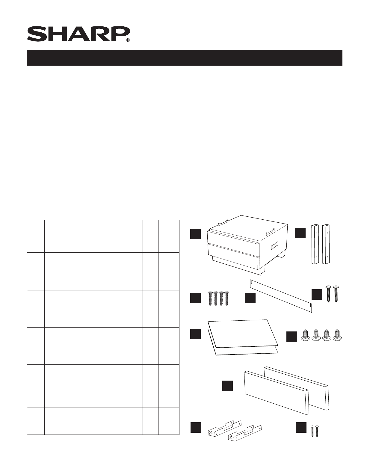
ITEM PART NAME QTY
UTC PEDESTAL
A
DPED-B002MRK0
MOUNTING CLEATS
B
SPAK-B128MRE0
MOUNTING CLEAT SCREWS
C
XMSS742P38000
TOE KICK
D
GCOVHB087MRT0
TOE KICK SCREWS
E
XUPS840P12X00
DRAWER MATS
F
PCOV-B009MRE0A
SCREW LEVELING
G
GLEGPB006MRE0
DRAWER DECORATION
H
HDECAC157MRP0
SUPERSTEAM OVEN
I
CONVERSION BRACKET
LANGTB464MRP0
1 N/A
2 AK
4 AA
1 AT
2 AA
2 AN
4 AC
2 BB
2 AP
PRICE
CODE
A
C
F
H
D
B
E
G
SUPERSTEAM OVEN
J
CONVERSION BRACKET SCREWS
LX-BZA148WREZ
Items B-J are available for ordering.
2 AA
I J
1
E
INSTALLATION INSTRUCTIONS
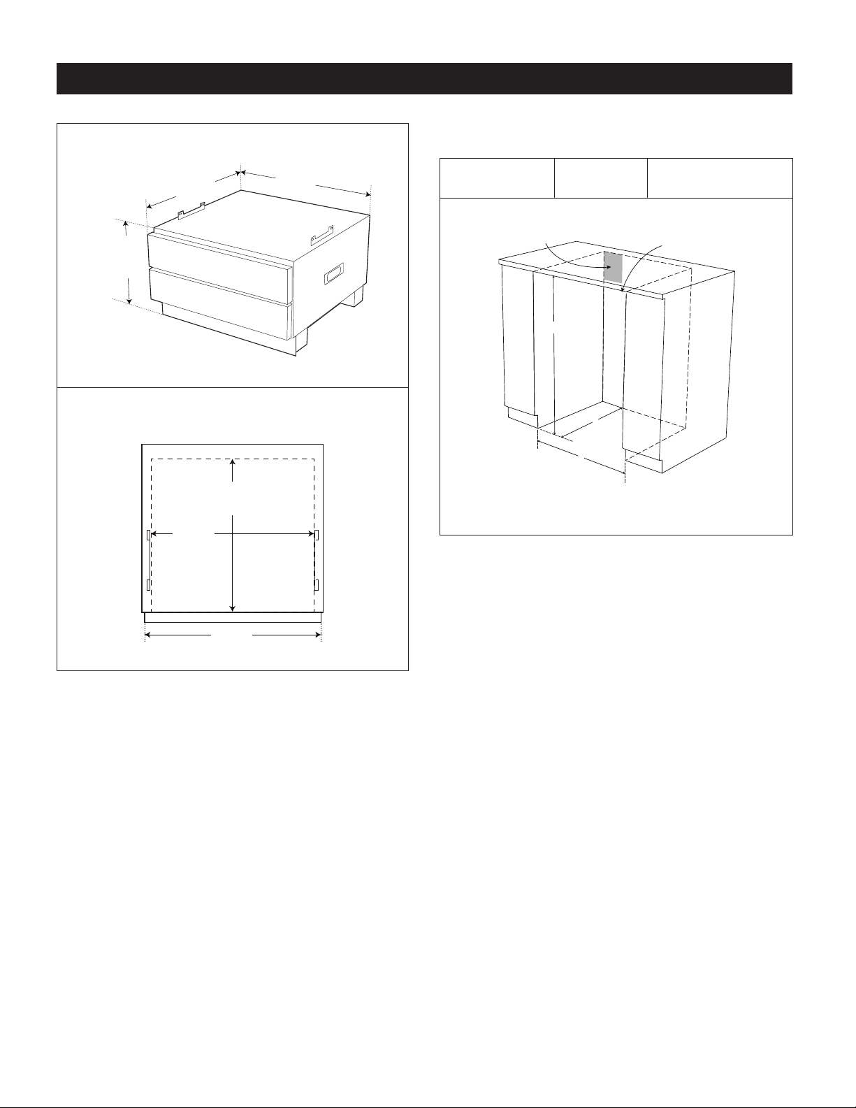
Overall Dimensions
1. Cabinet cutout dimensions. Prepare the cabinet opening
as shown in Figure 1.
14 7/16"
(366.7 MM) MIN
3
15
/4"
(390.5 MM) MAX
13
/16"
1
/2"
23
(596.9 MM)
23
(604.8 MM)
Inside Drawer Dimensions
21 13/16"
(554.0 MM)
11
/16"
18
(474.7 MM)
Height (A)
34 1/2" (876 mm)
SUGGESTED ELECTRICAL
OUTLET LOCATION
Width (B)
24" (610 mm)
A
C
B
FIGURE 1
Depth (C)
23 1/2" min. (597 mm)
*NOTE: INSTALLER PROVIDE
TOP FILLER IF NEEDED
11
/16"
23
(601.7 MM)
2E
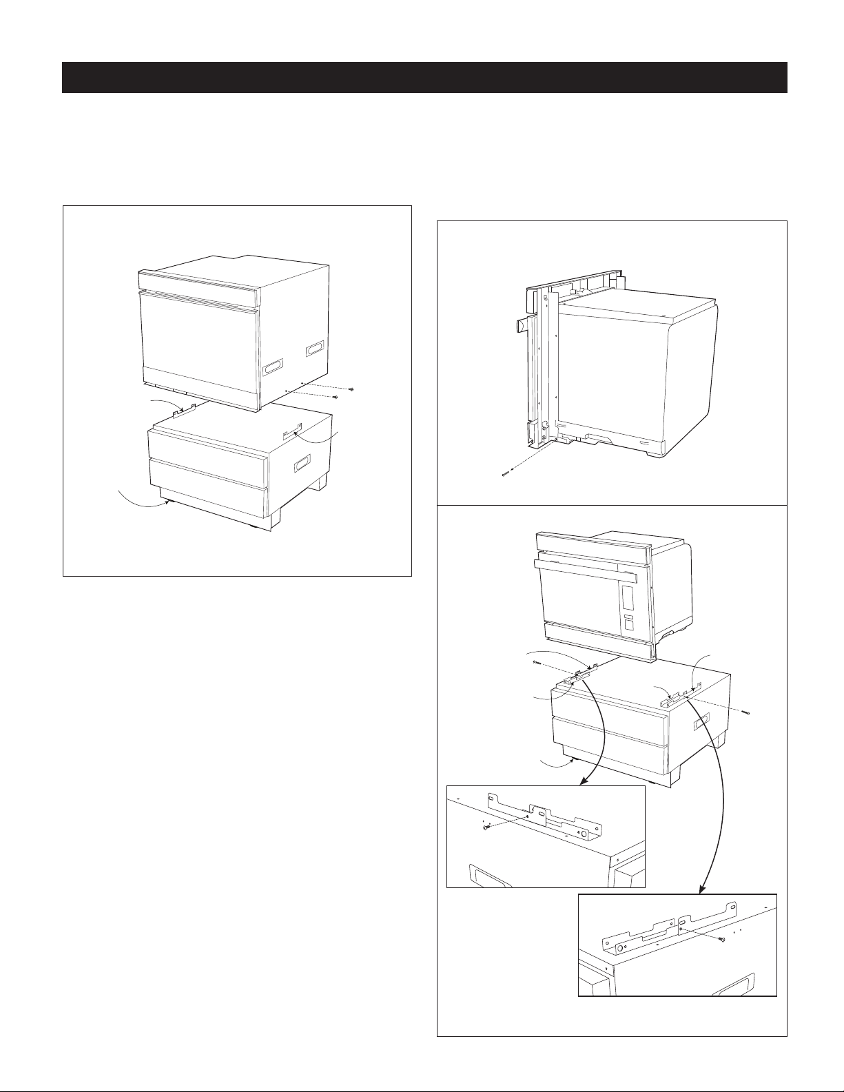
INSTALLATION INSTRUCTIONS
2. Convection Microwave Drawer - Place the oven on a
secure surface. Remove the 4 bottom screws (2 on each
side of the oven) as shown in Figure 2A. Carefully place
the oven on top of the pedestal in-between the mounting
rails on the left and right.
For Convection Microwave Drawer
LEFT
MOUNTING
RAILS
ADJUSTABLE
FEET
RIGHT
MOUNTING
RAILS
SuperSteam+ Oven - Place the oven on a secure surface.
Remove the 2 bottom screws (1 on each side of the
oven) as showing in Figure 2B. Install the two conversion
brackets with the two provided screws (J). See Figure 2C.
Carefully place the oven on top of the pedestal in-between
the conversion brackets on the left and right.
For SuperSteam+ Oven
FIGURE 2B
FIGURE 2A
LEFT
MOUNTING
RAILS
BRACKET
ADJUSTABLE
FEET
BRACKET
RIGHT
MOUNTING
RAILS
FIGURE 2C
3
E
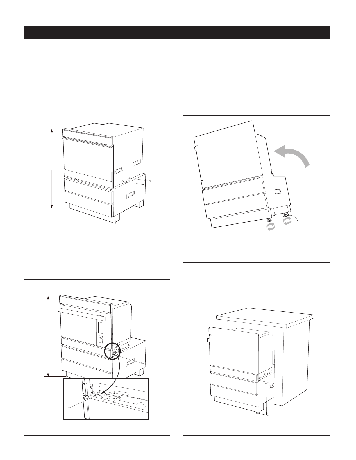
INSTALLATION INSTRUCTIONS
3. Align the front face of the oven with the front face of the
pedestal drawers. Once positioned, fasten the oven to the
pedestal.
Convection Microwave Drawer - Use the same 4
removed screws from Step 2. See Figure 3A.
Refer to oven installation instructions for the models'
*
specic below-the-counter clearance guidelines.
For Convection Microwave Drawer
*
4. Adjust the height of the overall unit to t your specic
opening. The pedestal contains 4 adjustable feet. To
adjust, have one person tilt the unit to one side while the
other person adjusts the 2 feet on the raised side to the
desired height. Repeat this step by tilting the unit to the
other side and adjusting the other 2 feet. Ensure that all
feet are adjusted equally to balance the unit. See Figure 4.
CAUTION: Do not tilt forward. The pedestal drawers will
extend out.
FIGURE 3A
SuperSteam+ Oven - Use the 2 removed screws from
Step 2. See Figure 3B.
Refer to oven installation instructions for the models'
*
specic below-the-counter clearance guidelines.
For SuperSteam+ Oven
*
USE CHANNEL LOCK OR
SLIP-JOINT PLIERS TO
LOOSEN THE FEET
PRIOR TO ADJUSTMENT
FIGURE 4
5. Once the overall height has been conrmed, measure the
distance from the top surface of the pedestal unit to the
oor. See Figure 5. This measurement will be needed for
the installation of the wooden mounting cleats.
A
FIGURE 3B
FIGURE 5
4E
INSTALLATION INSTRUCTIONS
SUPPLIED DRAWER FACES ARE 1
/16"
*NOTE: ATTACH CABINET FILLER STRIP IF NEEDED
LEVEL UNIT TO DESIRED HEIGHT
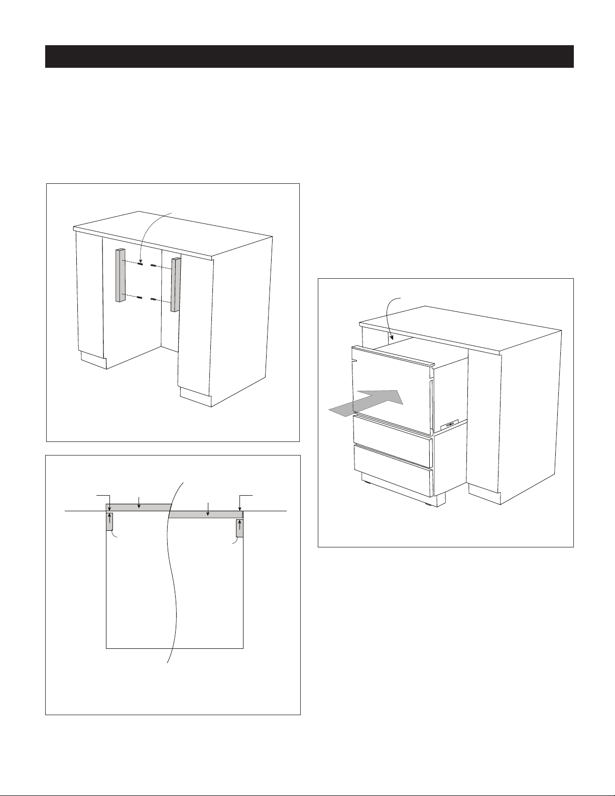
6. Install the wooden cleats. Align the bottom of the cleat to the
measurement from Step 5. The pedestal can be installed
ush or standard with the face of the cabinet. Depending
on the preference, the depth of the cleat position should
be adjusted as such. See Figure 6. Position each cleat and
mark the holes on the cabinet. Pre-drill each hole in the
cabinet using a 1/16" (1.6 mm) drill bit. Attach both cleats
using the 4 mounting cleat screws. See Figure 7.
MOUNTING CLEAT SCREWS
7. Slide the unit into the opening. Plug oven into the wall
receptacle prior to pushing the unit all the way in. See
Figure 8. The mounting angles of the oven should rest
against the installed wooden cleats.
NOTE:
• To aid in sliding the unit into the space, open the bottom
drawer and use middle frame to push into place. In
addition, there are built-in handles on each side of
the pedestal that can assist in the movement of the
unit. Tuck cord behind the oven before pushing the
assembled unit in.
• If the chosen height of the installation presents a gap
between the counter top and the unit, attach cabinet
ller strip as noted in Figure 8. Cabinet ller strip can be
purchased wherever cabinets are sold.
FIGURE 6
STANDARD MOUNT
UTC DRAWER FACE
X
CLEAT
*NOTE: WHEN USING CONTRACTOR CABINET FACES,
ADD OR SUBTRACT ADDITIONAL DIMENSION.
UTC DRAWER FACE
CLEAT
3
FIGURE 7
FLUSH MOUNT
Y
CABINET FACECABINET FACE
FIGURE 8
5
E
 Loading...