

Page 1
SERVICE MANUAL
This document has been published to be used for
after sales service only.
The contents are subject to change without notice.
Refrigerator-freezer
MODEL
SJ-GF60X-T
No.S0310SJF60XTFT
DESTINATION F
CONTENTS
Refer to "REFRIGERATING-CYCLE REPAIR MANUAL" for handling this refrigerant.
Refrigerant; R600a
[1] PRODUCT SPECIFICATIONS
1. SPECIFICATIONS ………………………… 2
2. ACCESSORIES …………………………… 2
3. AUTOMATIC ICE MAKING ……………… 3
[2] DESIGNATION OF VARIOUS PARTS
1. PART NAMES ……………………………… 4
2. INTERNAL STRUCTURE ………………… 5
3. FLOW OF COOL AIR ……………………… 6
4. TEMPERATURE DISTRIBUTION ………… 7
[3] DIMENSIONS
1.
OUTER DIMENSIONS AND CLEARANCE
…8
2. INNER DIMENSIONS ……………………… 9
[4] ELECTRICAL CIRCUIT DIAGRAMS …………10
1. WIRING DIAGRAM …………………………10
2. ELECTRIC ACCESSORIES LAYOUT ……11
3.
PRECAUTIONS FOR USING LEAD-FREE SOLDER
……12
[5] ELECTRICAL SYSTEM SPECIFICATIONS …13
1. FUNCTIONAL PART SPECIFICATIONS …13
2. MODE FOR DISPLAY ……………………… 14
[6]
REFRIGERATION CYCLE SYSTEM SPECIFICATIONS
1. R600A PRECAUTIONS ……………………15
2.
TABLE OF R600A CHARACTERISTICS
…1 5
3. REFRIGERATION CYCLE DIAGRAM …… 15
4.
REPAIR OF THE REFRIGERATION CYCLE
…17
[7] TROUBLESHOOTING
1. SELF-DIAGNOSIS MODE …………………18
2.
FORCED STOPPING OF DOOR ALARM BUZZER
…2 2
3.
THERMISTOR CIRCUIT CHECK METHOD
…22
4.
INSPECTION FLOWCHART AND REPAIR ITEMS
…2 3
5.
PLASMACLUSTER OK/NG JUDGMENT
…25
[8] DISASSEMBLY/ASSEMBLY
1.
GENERAL DISASSEMBLY SEQUENCE
…26
2.
REFRIGERATOR COMPARTMENT DISASSEMBLY
…2 7
3. FREEZER COMPARTMENT/ICE
COMPARTMENT DISASSEMBLY ………29
4. HOW TO REMOVE OP. PWB ASS'Y …… 31
5. HOW TO REMOVE TERMINAL BOX ……31
6. HOW TO INSTALL R-SUB PACKING ……32
7.
HOW TO INSTALL DUCT RT ASS'Y COVER
…33
8.
ADJUSTMENT OF R-DOOR (DOUBLE DOOR)
…3 4
9. MAIN PARTS ASSEMBLY …………………35
Parts Guide
Page 2
SJGF60XT
2
[1]
PRODUCT SPECIFICATIONS
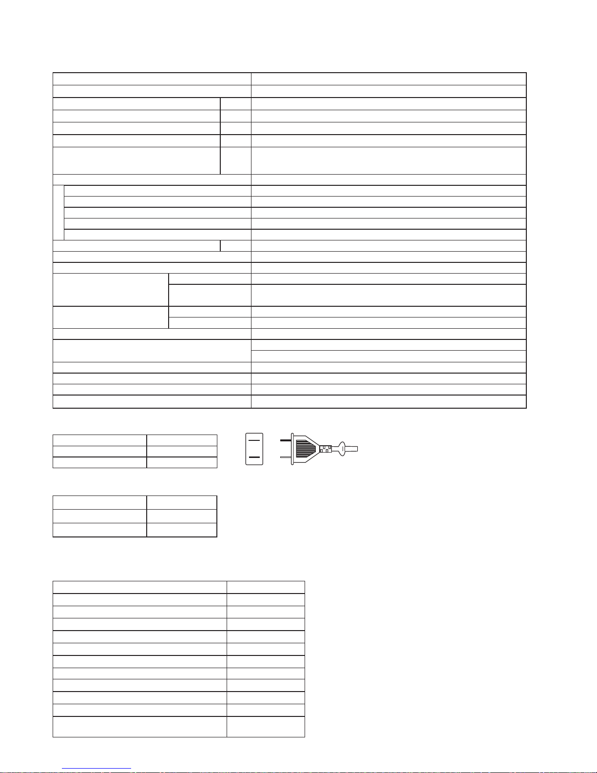
SPECIFICATIONS1.
Item SJ-GF60X-T
Rated voltage/Rated frequency 110V~60Hz
Rated input (W) 127
Rated power input of heating systems (W) 189
Defrosting input (W) 155
Defrosting heater input (W) 155
O u t e r d i m e n s i o n s
Width×Depth×Height
(mm) 750 x 728 x 1820
Rated total storage volume 601L (21.2 cu.ft.)
Refrigerator compartment 315L (11.13 cu.ft.)
Freezer compartment (upper) 37L (1.31 cu.ft.)
Freezer compartment (lower) 120L (4.24 cu.ft.)
Ice compartment 19L (0.67 cu.ft.)
Vegetable compartment 110L (3.89 cu.ft.)
Weight (kg) 106
Refrigerant (Charging quantity) [Flammable] R600a (72g)
Insulation blowing gas [Flammable] Cyclo pentane (HC)
Cabinet
Inner box material ABS plastic
Outer shell material
PET steel
(Hot dipped zinc plated steel sheet with baked polyester resin coating)
Door
Door shell material Glass
Door inner material ABS plastic
Temperature control Automatic(adjustable)
Defrosting system
Heater system
(automatic start, automatic fi nish)
Refrigerator lamp LED (8 pcs)
Adjustable legs 2
Casters 4
Climate class ST
PLUG TYPE
Plug cord 2pin
Plug type A-1
Destination mark F
COLOR
Items -T
Outside color Brown
Inside color White
ACCESSORIES2.
Refrigerator Compartment
R shelf 2
Free set shelf (left) (front/back) 1 each
Free set shelf (right) (front/back) 1 each
Chilled case 1
Chilled case tray 1
Case 1
Door pocket (left) 2
Door pocket (right) 2
Egg case 1
Egg tray 1
Bottle pocket (left/right) 1each
Water tank (Tank cap, Lock lever, Slide cap,
Filter case, Water tank, Water fi lter)
1
Page 3
SJGF60XT
3
Freezer compartment (Upper)
Freezer case (Upper) 1
Stainless tray 1
Freezer compartment (Lower)
Freezer case (top) 1
Freezer case (bottom) 1
Ice compartment
Ice storage box 1
Noise-proof sheet 1
Ice scoop 1
Vegetable compartment
Vegetable case 1
Fruit case 1
Pet case 1
Stainless tray 1
Other Accessories and Printed Materials
Foot grille 1
Operation manual 1
Warranty card 1
Control label 1
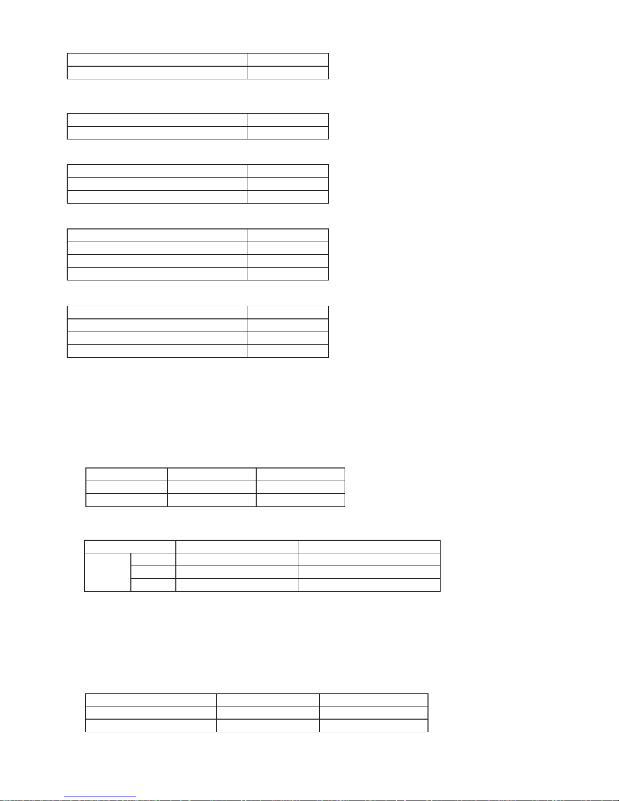
AUTOMATIC ICE MAKING3.
Water supply method: Storing water in tank/Direct water supply to ice cube maker•
Water tank volume: Approx. 1.2 L•
Ice making capacity (External air temperature: 30ºC, No door opening/closing, Temperature control: “•
中
”, Ice-making mode: “通常”)
Ice cube size Standard Large
Daily Approx. 1.2 kg Approx. 1.5 kg
Once (8 pieces) Approx. 100 g Approx. 230 g
Ice-making time/once•
Ice cube size Standard Large
Ice making
mode
通常
Approx. 2 hours Approx. 3 hours and 30 minutes
キラット
Approx. 6 hours Approx. 8 hours
おいそぎ
Approx. 1 hour and 20 minutes Approx. 2 hours
Others: Water filter is attached.•
Ice scoop is provided.
Enables test operation with the cleaning function.
Heat-resistant temperature of water tank: Approx. 60ºC•
Ice storage quantity•
Ice cube size Standard Large
Normal Approx. 48 to 64 pcs. Approx. 24 to 32 pcs.
Maximum (when leveled) Approx. 96 to 112 pcs. Approx. 40 to 48 pcs.
Page 4
SJGF60XT
4
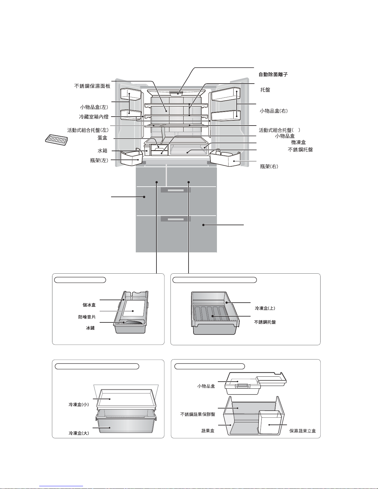
[2] DESIGNATION OF VARIOUS PARTS
PART NAMES1.
Parts names in parentheses "[ ]" are denominations used in the Operation manual.
ྑ
>@
Ice compartment Freezer compartment (upper)
Freezer compartment (lower)
Freezer compartment (lower)
Noise-proof sheet
Ice storage box
Ice scoop
F case sus
F case s
F top case
F bottom case
Vegetable case
Fruit case
V case sus
Pet case
Vegetable compartment
Vegetable compartment
Free set shelf(left)
Egg case
Egg tray
Water tank
Bottle pocket(left) Bottle pocket(right)
Cool plate
Door pocket(left)
Door pocket(right)
Case
Chilled case
C case tray
LED
[ ]
[ ]
[ ]
[ ]
[ ]
[ ]
[ ]
[ ]
[ ]
[ ]
[ ]
[ ]
[ ]
[ ]
[ ]
[ ]
[ ]
[ ]
[ ]
[ ]
[ ]
[ ]
[ ]
[ ]
Free set shelf(right)
Plasmacluster unit
R shelf
[ ]
Page 5
SJGF60XT
5
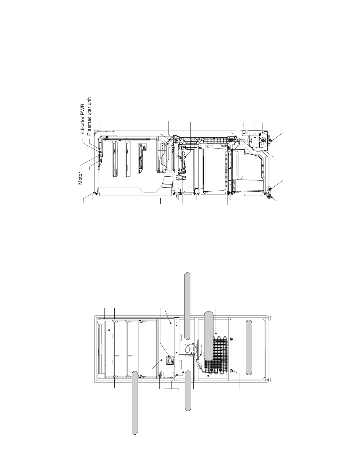
INTERNAL STRUCTURE2.
Catalyzer
Humidity sensor
Fan motor
Proximity switch
Thermo fuse
Fan motor
Catalyzer
Ice compartment
Freezer compartment (upper)
Freezer
compartment (lower)
Vegetable compartment
Refrigerator compartment
R-shower duct ass’y
D-fan motor PCI
Damper ass’y
V heater
Thermistor
Ice cube heater
Evaporator
Terminal box
(Main PWB, EECON-INV PWB, REACTANCE)
Compressor, protector, valve turret
Fan motor g
Condenser unit
Caster
Evaporating pan
Side view
Adjustable leg ass’y
F proximity switch
Ice maker ass’y
OP.PWB
Transparant electrode
R door switch
LED PWB ass’y
Cool plate
LED PWB ass’y
R-thermistor
Gear pump
Water pipe ass’y
Water pipe heater
Tank heater
F-thermistor
Evaporator
Heater
Front view
Fan motor f
DEF thermistor
Page 6
SJGF60XT
6
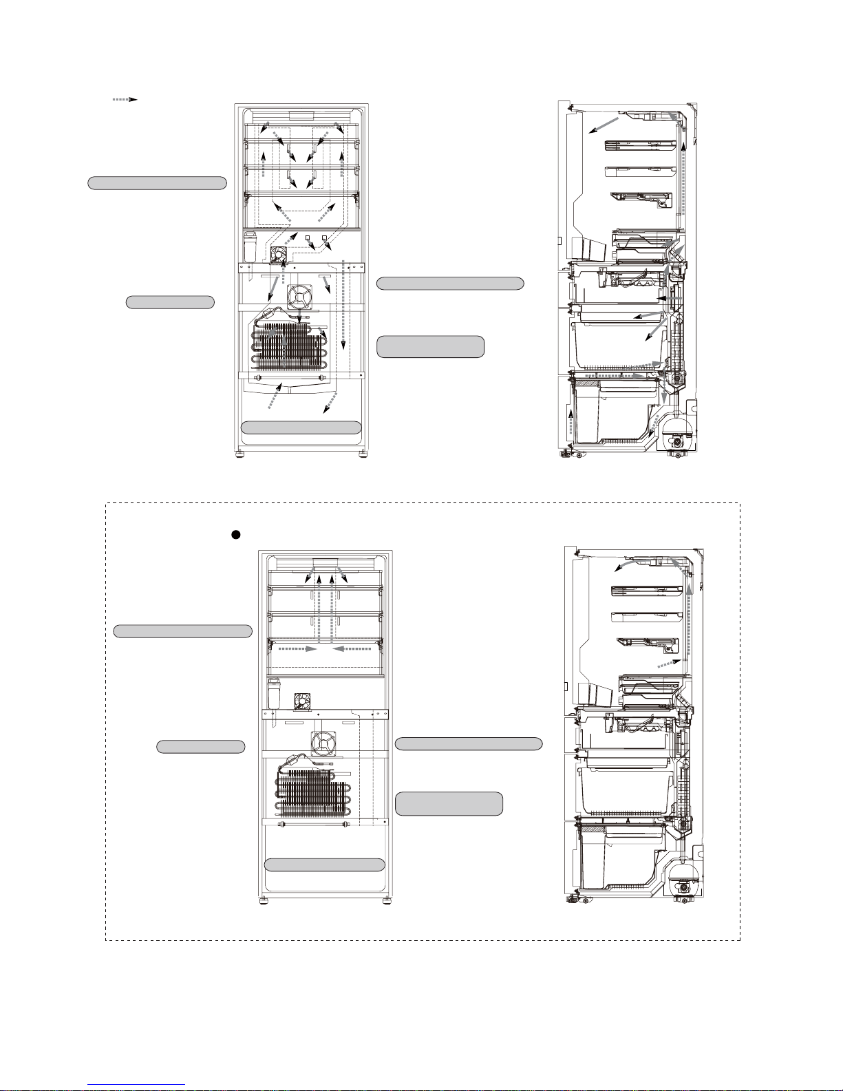
FLOW OF COOL AIR3.
Ice compartment
Freezer compartment (upper)
Freezer
compartment (lower)
Refrigerator compartment
Freezer
compartment (lower)
Vegetable compartment
Side view
Front view
Refrigerator compartment
Ice compartment
Freezer compartment (upper)
Vegetable compartment
Flow of Cool air
When Plasmacluster ion is in operation.
Page 7
SJGF60XT
7
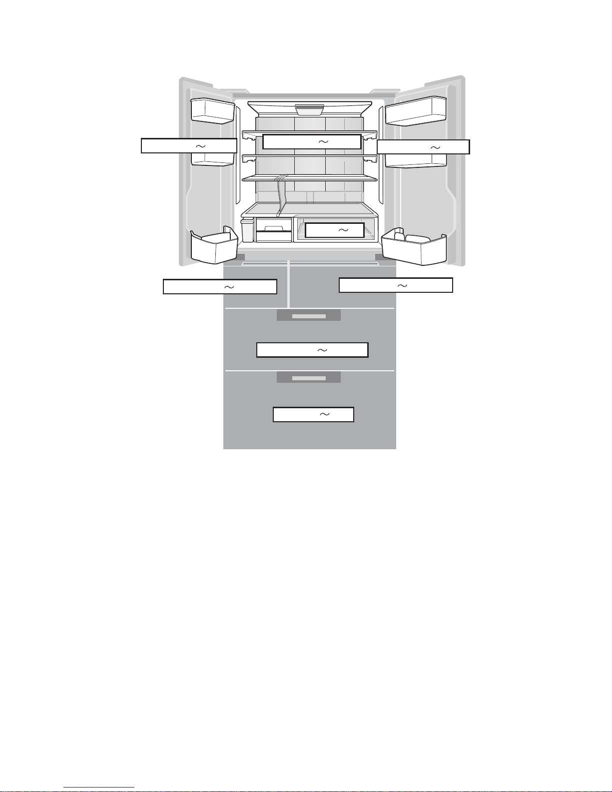
TEMPERATURE DISTRIBUTION4.
●
The temperatures above are indications under the condition of no
food inside, doors closed and surrounding temperature is 30 after
stabilized the inside temperature. (Temperature adjustment is "中")
Approx.3 7°C
Approx.2 5°C
Approx.3 7°C
Approx.0 2°C
Approx.-17 -19°C
Approx.-18 -20°C
Approx.-18 -20°C
Approx.3 8°C
Page 8
SJGF60XT
8
[3] DIMENSIONS
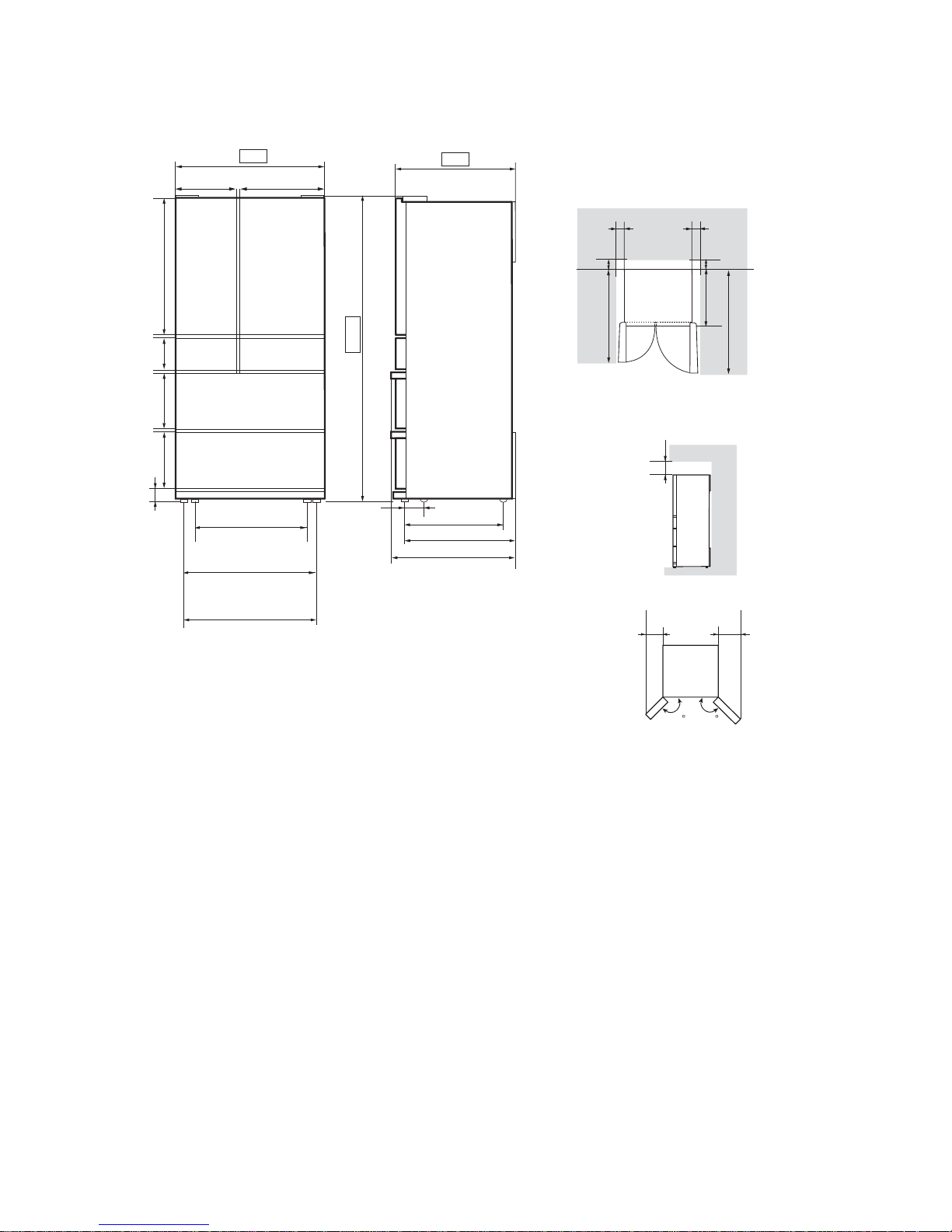
OUTER DIMENSIONS AND CLEARANCE (UNIT:mm)1.
174
230
728
285 461
616
697.5
691.5
641
68
691.5
4
750
1820
853.2180.8335
365
8
8
15.5
50
732.5
125 118
Moving wheels
back side
Moving wheels
front side
Adjustable feet
More than
960
1136
728
60 60
More than
More than
60
More than
60
More than
90
mm
Page 9
SJGF60XT
9
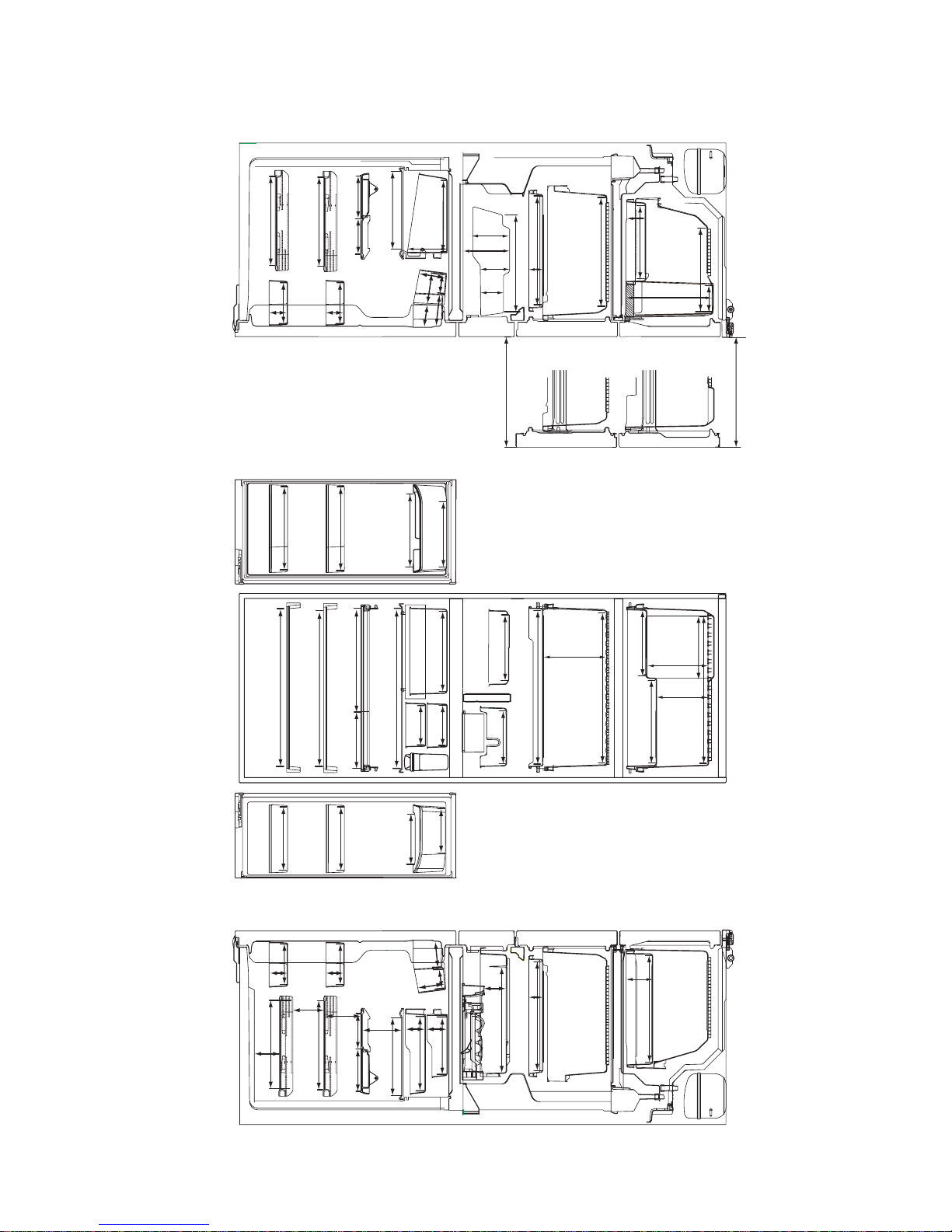
INNER DIMENSIONS2.
The dimensions between shelves can be changed by setting the shelves on the other rails.•
348
319
348
619
353
357
215
208
208
584
593
366
208
172
118
67
95
96
96
246
226
392
81.5
70
70
417.8
424
420
280
50
112
203
412
589
589
135
334
334
309
334
142
142
144
75
75
75
144
75
122
123
123
123
135
94
163
417.8
105
66
100
71
348
311911
319
348
50
424
597
282
310
63
353
88
105
404
110.5
138.5
95.5
89
440
119 113
125
140
Page 10
SJGF60XT
10
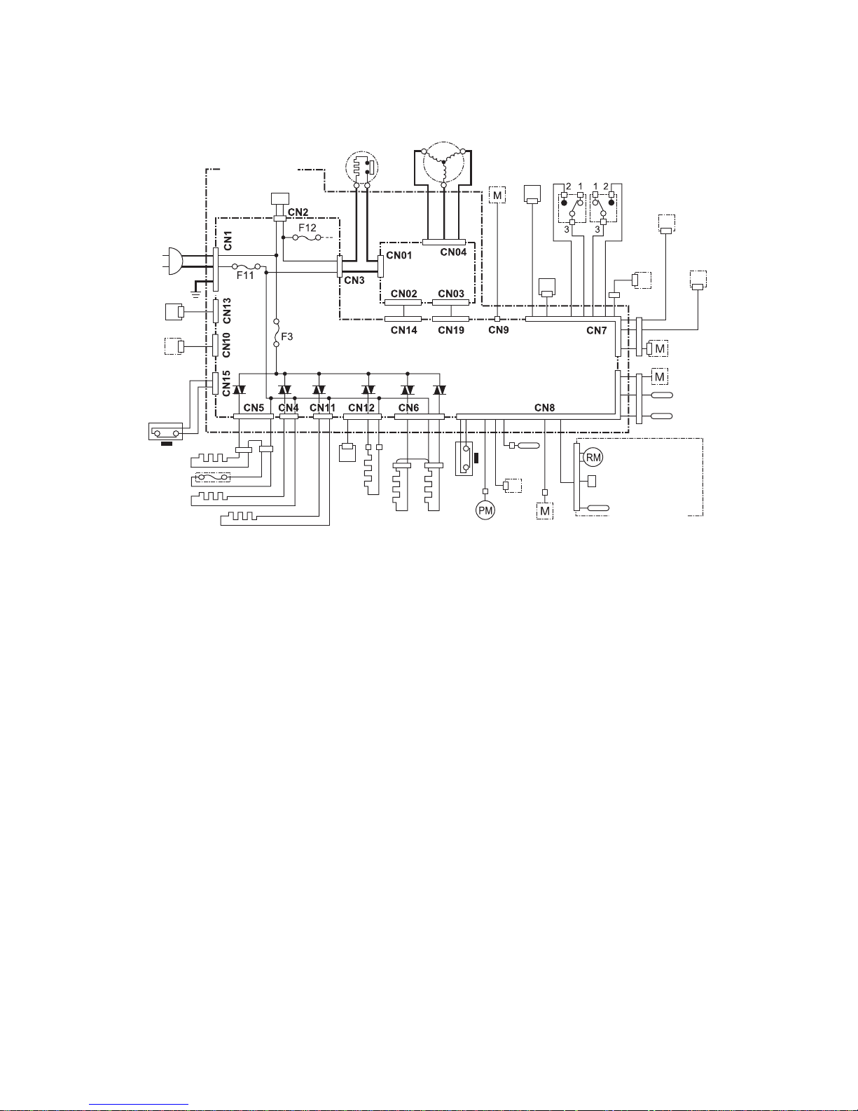
[4] ELECTRICAL CIRCUIT DIAGRAMS
WIRING DIAGRAM1.
Source cord
Reactance
Main PWB
OP
PWB
EECON-INV
PWB
Protector
Compressor
Fan
motor g
Fan
motor f
R-fan
motor
LED
PWB
(left)
Indicator
PWB
Plasmacluster
unit
Motor
D-fan motor PCI
Gear
pump
Damper
R
thermistor
F thermistor
DEF thermistor
Ice maker unit
Motor
Switch
Thermistor
Proximity
switch
F proximity
switch
Ice cube
heater
Water
pipe
heater
R door
heater
V heater
Door
switch
(left)
Door
switch
(right)
LED
PWB
(right)
Terminal box
Valve turret
Humidity sensor
Heater
Thermo fuse
Tank heater
Page 11
SJGF60XT
11
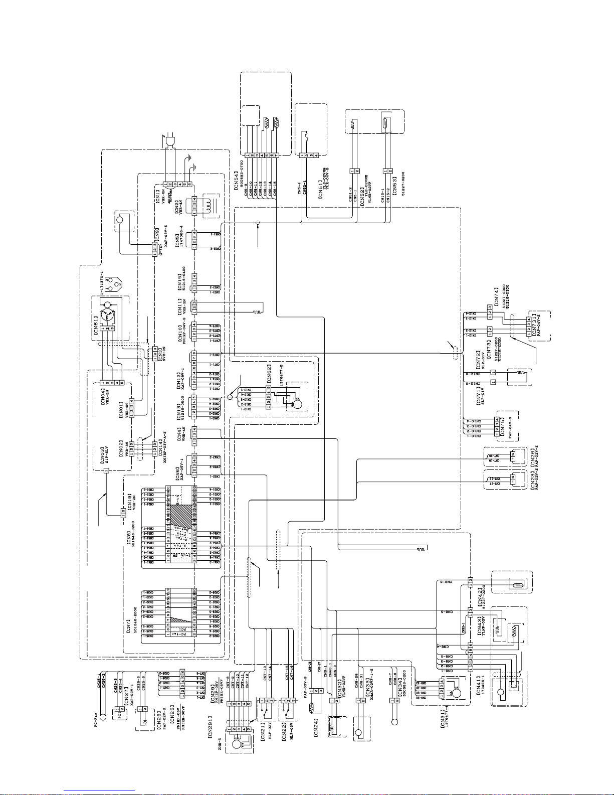
ELECTRIC ACCESSORIES LAYOUT2.
Black
Blue
Brown
Compressor
Compressor ass’y
Comp. harness
Red
Inverter DC harness
EECON-INV PWB
White
Green
Earth harness
MAIN PWB
Terminal box
Indicator
PWB
Red
Gray
Orange
White
Yellow
Black
Motor
Brown
Brown
Black
White
White
White
Brown
Brown
White
White
Red
Black
Red Purple
Gray
Black
Purple
Gray
Red
Red
Orange
Orange
Orange
Orange
Yellow
Yellow
Blue
Light green
Light green
Light green
Damper harness
Gray
Blue
Reactance
G-fan
Reactance
Fan motor
F thermistor
DEF thermistor
Heater
F-proximity switch
V-heater
Humidity sensorR door heaterOP.PWB
Valve turret
Tank heater
Harness
Harness
Harness
Harness
Black
Black
Black
White
Heater
Thermo fuse
Blue
Red
Red
Orange
Yellow
Light green
White
White
White
White
Blue
Blue
Black
Black
Brown
Yellow
Black
Brown
F proximity
switch
Gray
Brown
Brown
Red
Harness
OP PWB
R door
heater
Humidity
sensor
LED PWB
(left)
Ice cube tray
Ice cube heater
Light
green
Blue
Brown
Light
green
Thermistor
Ice maker unit
Harness
R-damper
R fan motor
Gear pump
Water pipe
R thermistor
R door switch
(left)
R door
switch(right)
Water pipe
heater
SW
Motor
LED PWB
(right)
Ice cube heater
Gear
pump
R
damper
Water pipe heater
Source cord
Black
White
WhiteWhiteYellowBrown
V-heater
harness
Valve turret
Valve turret
Green
/Yellow
Green
/Yellow
Protector
Black
Yellow
Proximity switch
Moter
Tank heater
Proximity
switch
Black
Brown
Blue
Black
Red
Gray
Red
Red
Blue
Orange
Light green
Yellow
Yellow
White
White
White
White
White
Light green
Black
White
Gray
White
White
Gray
Brown
Brown Brown Brown
Blue Blue
Gray
Red
Red Red Red
Orange
Yellow
Orange
Orange
Orange
Yellow
Yellow Yellow
Blue
Red
Brown
Red
Red
Red
Brown
Brown
Brown
Brown
Brown
Brown
Brown
Brown
Brown
Brown
Brown
Red
Brown
Brown
White
White
White
White
White
White
White
Orange
Orange
Orange
Orange
Orange
Orange
Orange
Orange
Purple
Purple
Orange
Light green
Light green
Light green
Light green
Light green
Light green
Light green
Light green
Red
Red
Red
Red
Red
Red
Red
Red
Orange
Yellow
Yellow
Yellow
Yellow
Yellow
Yellow
Yellow
Yellow
Yellow
Light green
Blue
Blue
Blue
Blue
Gray
Blue
Blue
Black
Black
Black
Black
Black
Gray
Gray
Gray
Gray
Gray
Gray
Yellow
Orange
White
Motor
Indicator PWB
LED PWB(right)
LED PWB(left)
R door switch(left)
R door switch(right)
Green
Blue
Brown
Page 12

SJGF60XT
12
PRECAUTIONS FOR USING LEAD-FREE SOLDER3.
1) Employing lead-free solder
The PWB of this model employs lead-free solder. This is indicated by the "LF" symbol printed on the PWB and in the
service manual. The suffi x letter indicates the alloy type of the solder.
Example:
Indicates lead-free solder of tin, silver and copper
2) Using lead-free wire solder
When repairing a PWB with the "LF" symbol, only lead-free solder should be used. (Using normal tin/lead alloy
solder may result in cold soldered joints and damage to printed patterns.)
As the melting point of lead-free solder is approximately 40°C higher than tin/lead alloy solder, it is recommend that a
dedicated bit is used, and that the iron temperature is adjusted accordingly.
3) Soldering
As the melting point of lead-free solder (Sn-Ag-Cu) is higher and has poorer wettability, (fl ow), to prevent damage
to the land of the PWB, extreme care should be taken not to leave the bit in contact with the PWB for an extended
period of time. Remove the bit as soon as a good fl ow is achieved.The high content of tin in lead free solder will
cause premature corrosion of the bit. To reduce wear on the bit, reduce the temperature or turn off the iron when it is
not required.
Leaving different types of solder on the bit will cause contamination of the different alloys, which will alter their
characteristics, making good soldering more diffi cult. It will be necessary to clean and replace bits more often when
using lead-free solder. To reduce bit wear, care should be taken to clean the bit thoroughly after each use.
Page 13
SJGF60XT
13
[5] ELECTRICAL SYSTEM SPECIFICATIONS
FUNCTIONAL PART SPECIFICATIONS1.
Part Name Specifi cations Function
Fan motor F
(F fam motor)
Model No.: 4715JL-09W-S37-GF8
Rating: DC15V
Power Input: 1.05W (Vs:2.6V)
For cooling
(For freezer compartment)
Fan motor
(R fam motor)
Model No.: D08A-12PM
Rating: DC12V
Power Input: 0.84W
For cold air circulation
(For refrigerator compartment)
Fan motor g
(condenser fan motor)
Model No.: 4515JL-09W-S10-G01
Rating: DC15V
Power Input: 1.2W
For condensing
(Out side refrigerator)
D-fan motor PCI
Model No.: D09F-12SM20(EX)
Rating: DC12V 0.13A
Power Input: 1.56W
For ion releasing
(For refrigerator compartment)
Damper ass'y (R damper) 415 ± 5Ω (25°C) For refrigerator compartment temperature control
Motor Rating: DC12V 0.13A 300Ω Deodorant/bacteria elimination switching damper
Door switch
(R door switch)
5mA 5V DC
For detection of opening or closing of the door
(For refrigerator compartment)
Proximity switch
(I door switch)
DC15V 100mA 1W
For detection of opening or closing of the door
(For Ice compartment)
F proximity switch
(Freezer (bottom) door switch)
DC15V 100mA 1W
For detection of opening or closing of the door
(For freezer compartment (bottom))
Compressor
Model No.: VESD9C+
Rating: 100V 50/60Hz
Resistance value: 9.6Ω (at 25°C)
Protector
MODEL: MSP59AMN-6
Operating temperature: 120°C
For compressor overload prevention
Main PWB For main control
OP.PWB For operation panel control (touch panel)
LED PWB 15V 72mA 1.125W For refrigerator compartment illumination
Indicator PWB 3.2V 20mA 64mW
Source cord 125V 7A Source cord (2 Pin + earth)
F thermistor Resistance: 6.4kΩ (at 0°C) For detection of the freezer compartment temperature
R thermistor Resistance: 6.4kΩ (at 0°C) For detection of the refrigerator compartment temperature
DEF thermistor Resistance: 15kΩ (at 0°C) Senses when defrosting is completed
Thermo fuse
Rating: 250 V 10 A
Rated operating temperature: 77°C
For defrosting temperature excessive rise prevention
Thermistor Resistance value: 6.0kΩ (at 0°C) For detection of ice tray temperature
Gear pump Supplies water to the ice cube maker
Heater 110V 155W 78Ω For defrosting
Plasmacluter unit DC15V 34mA For bacteria elimination in compartment
Reactance 11mH±10% Class E wiring
EECON-INV PWB 100V 50/60Hz For compressor drive
Ice cube heater 12W 833Ω For making clear ice cube
Humidity sensor 0.5mA 5V DC For detection of outside temperature and humidity
Valve turret For switching refrigerant
Partition heater(R door heater) 3.4W/2910Ω For refrigerator compartment door condensation prevention
Water pipe heater 2.8W/3565Ω For water pipe freezing prevention
Tank heater 1.0W/9638Ω Avoid the water tank from freezing
V heater ass'y 9.0W/1110Ω For vegetable compartment temperature compensation
:Unexchengeable parts or Independently unexchangeable parts.
Page 14

SJGF60XT
14
MODE FOR DISPLAY2.
How to set the product in this mode2-1.
Open the doors of the refrigerator compartment and the ice compartment within 2 minutes after turning ON the •
power to the main unit, and press and hold the [
戻る
] button for 5 seconds or longer.
How to cancel this mode2-2.
With the doors of the refrigerator compartment and the ice compartment opened, press and hold the [•
戻る
] button
for 5 seconds or longer.
Even if the main power supply is turned OFF, the display mode will be maintained. (not be cancelled)
Operation in the display mode2-3.
Each load (compressor, each fan motor, all heaters, damper, ice release motor, water pump motor) stops.1)
The damper is normally kept opened.2)
Even if the ice compartment or the refrigerator compartment (lower) door is opened, the door-open buzzer does 3)
not sound.
When the refrigerator compartment door is opened:4)
The refrigerator compartment illumination lamp and indicator LED are lit.•
The cooling/refrigerator compartment PCI fan motor operates.•
The door-open buzzer does not sound.•
Operation panel5)
<Outside of compartment>
The operation panel lamps on the door will blink in sequence one by one.•
Page 15
SJGF60XT
15
[6] REFRIGERATION CYCLE SYSTEM SPECIFICATIONS
R600A PRECAUTIONS1.
•Do not use any refrigerant other than R600a.
•Gas leak testers for HFC-134a, CFC-12, HCFC-22, etc., cannot be used.
•A special tool is used for the R600a cycle.
TABLE OF R600A CHARACTERISTICS2.
Refrigerant saturated vapor pressure table R600a
(Unit) Temperature: °C, Pressure: kgf/cm abs
Temperature
Pressure
-20 -15 -10 -5 0 10 15 20 25 30 35 40 45 505
0.74
1.601.340.91 1.11 1.91 2.25 2.64 3.08 3.58 4.13 4.74 5.42 7.006.17
(Unit)Temperature:°C, Pressure: MPa abs
Temperature
Pressure
-20 -15 -10 -5 0 10 15 20 25 30 35 40 45 505
0.073
0.1570.1310.089 0.109 0.187 0.221 0.259 0.302 0.351 0.405 0.465 0.532 0.6860.605
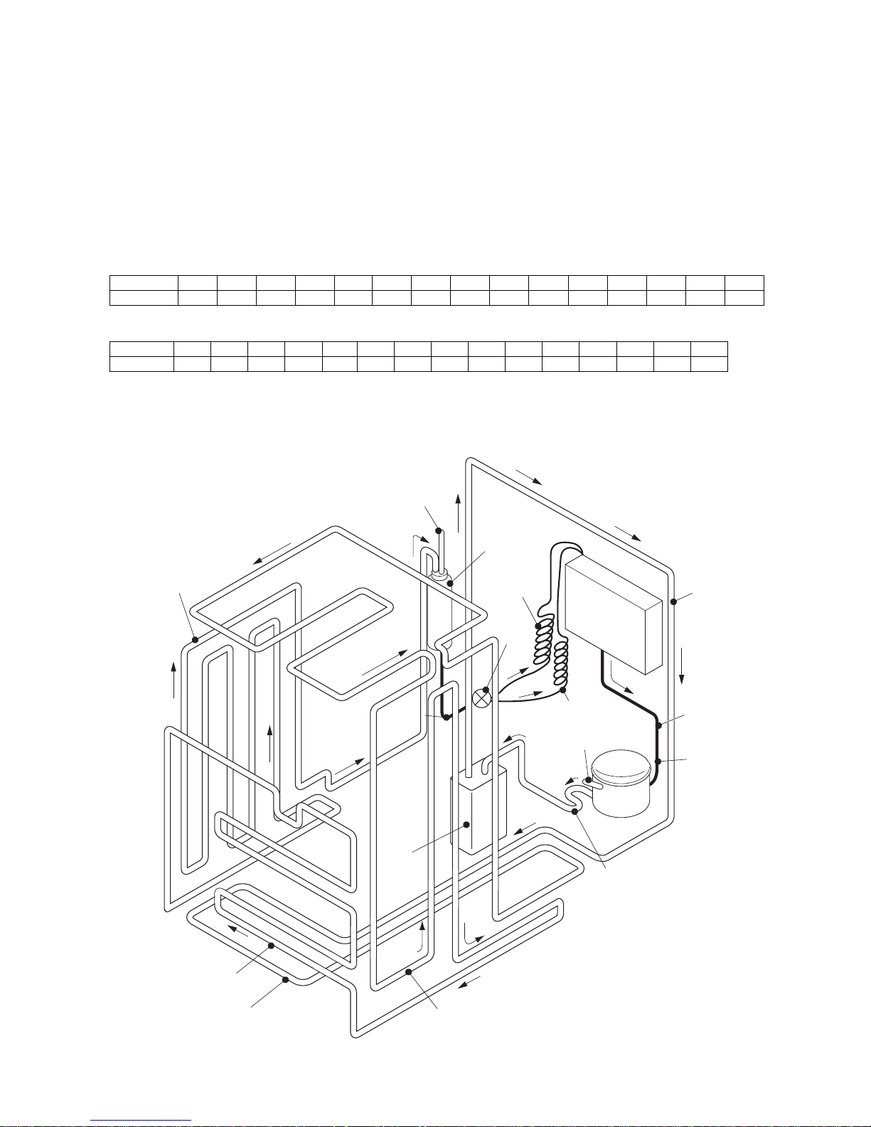
REFRIGERATION CYCLE DIAGRAM3.
Piping Diagram 3-1.
Evaporator
Charge pipe
Compressor
Discharge pipe
kit
Capillary
tube B
Dryer
Capillary
tube A
Charge pipe
①
②
③
⑤
⑦
⑨
⑬
⑮
⑪
⑧
④
⑯
⑫
⑥
⑩
⑭
⑰
⑳
⑲
⑱
Dew proofing condenser
Extra
cond.
unit kit
←(①~⑳)
Show the order ofthe refrigerant flow
Bottom
condenser
Back
condenser
Suction
connector
Suction
pipe
Valve
turret
Extension
barrel
Side
condenser L
Side
condenser R
Page 16
SJGF60XT
16
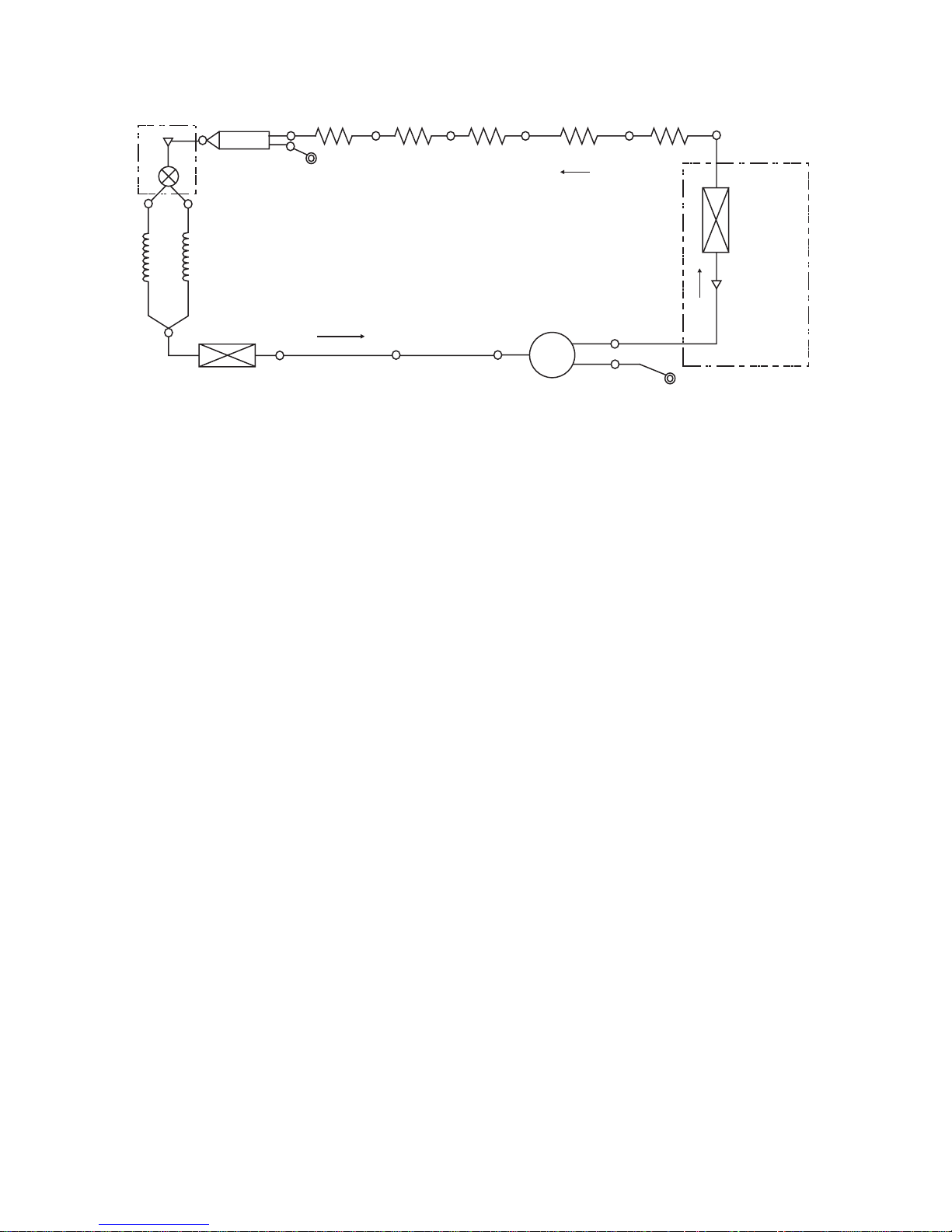
Schematic diagram3-2.
Suction connector
Compressor
Value turret kit
Suction pipe
Charge pipe
(Low presure side)
Capillary tube A
I. D.0.55
Side condenser L
Side
condenser R
Discharge pipe kit
Dryer
Back condenser
Bottom condenser
Evaporator
Charge pipe
(High presure side)
Extra cond. unit kit
Extra cond.
unit
D.P
condenser
Capillary tube B
I. D.0.7
Piping detail drawing3-3.
:
Side condenser R Outlet
Dew proofing condenser
Inlet
Side condenser R
Inlet
Suction pipe
Charge pipe
Discharge pipe
ass’y
Evaporating pan
Suction connector
Suction connector ass’y
Side condenser L
Outlet
Compressor
Charge pipe
R-valve ass’y
Dryer
Side condenser L
Inlet
Extra cond.unit
ass’y
Pinch point
Back condenser ass’y Outlet
Back condenser Inlet
Capillary tube B
Capillary tube A
Page 17
SJGF60XT
17
Specifi cations of Refrigerant Valve Operation3-4.
Modes and operating conditions of refrigerant valve (3-way valve)1)
Valve is fully closed:1.
• This mode is used in compressor OFF status.
Only fine capillary is opened:2.
• During normal cooling operation
Only wide capillary is opened:3.
• During cooling operation under large load
Both capillaries are opened4.
• The refrigerator is set in this mode for only one minute after the power supply is turned ON. This mode is used for
vacuuming. During cooling operation, this mode is not used.
• Differentiation between fi ne capillary and wide capillary
- Fine capillary: Capillary tube A
- Wide capillary: Capillary tube B
- The fi ne capillary is identifi ed with a yellow mark.
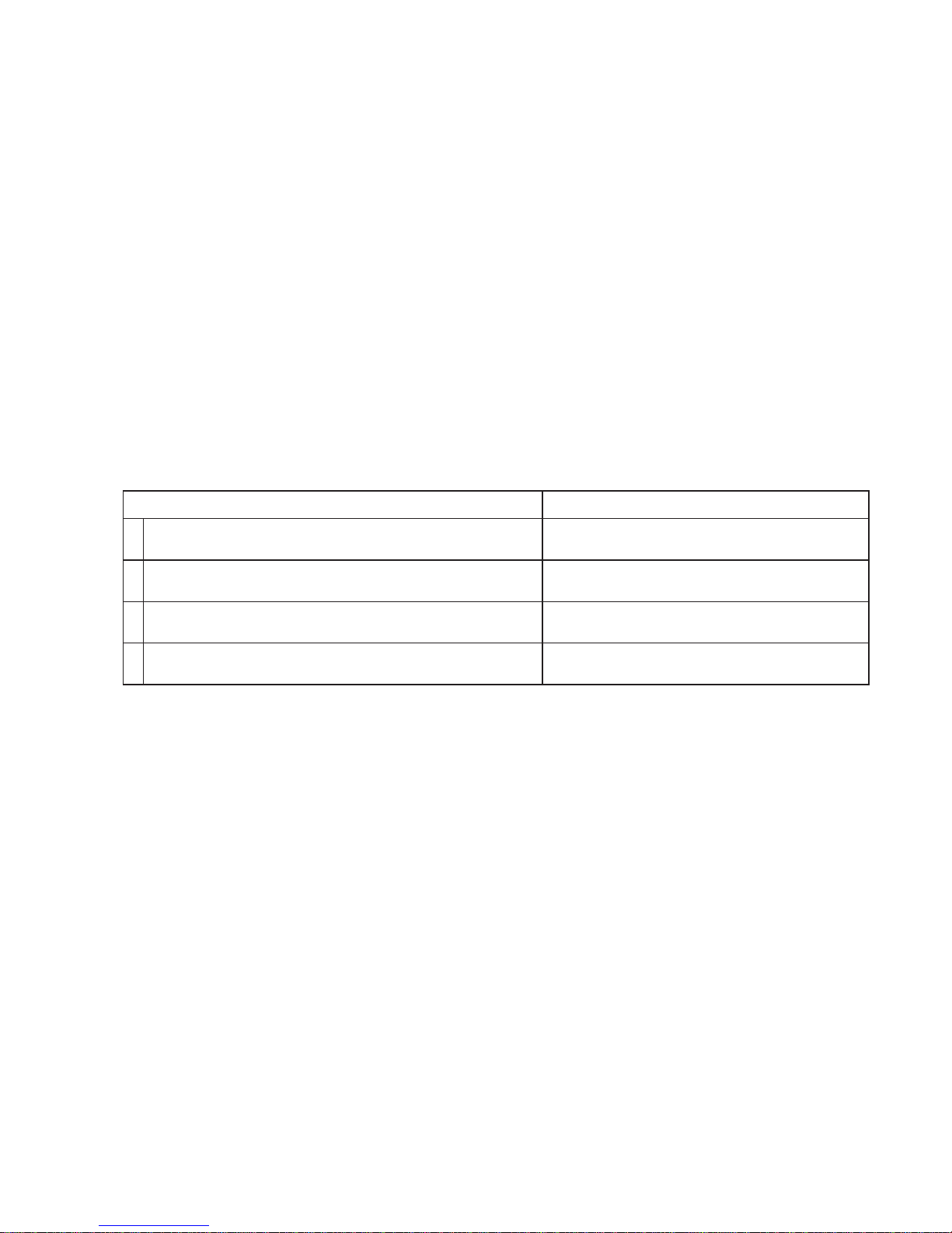
Fault and status of refrigerant valve2)
• There is no method to give an instruction from the PWB and confi rm the valve position.
Refrigerant valve status Problem
1
Both capillaries are opened, and the valve does not operate.
No problem on cooling operation
No problem
2
Only the fi ne capillary is opened, and the valve does not operate.
Cooling performance deteriorates under large load.
Refrigerant shortage may occur, causing frost around
the evaporator inlet to increase.
3
Only the wide capillary is opened, and the valve does not operate.
No problem on cooling operation
No problem
4
Both capillaries are closed, and the valve does not operate.
Cooling operation is disabled.
Cooling operation is disabled even when the
compressor is ON.
• Fault of the refrigerant valve cannot be displayed in the self-diagnosis mode.
Page 18
SJGF60XT
18
[7] TROUBLESHOOTING
SELF-DIAGNOSIS MODE1.
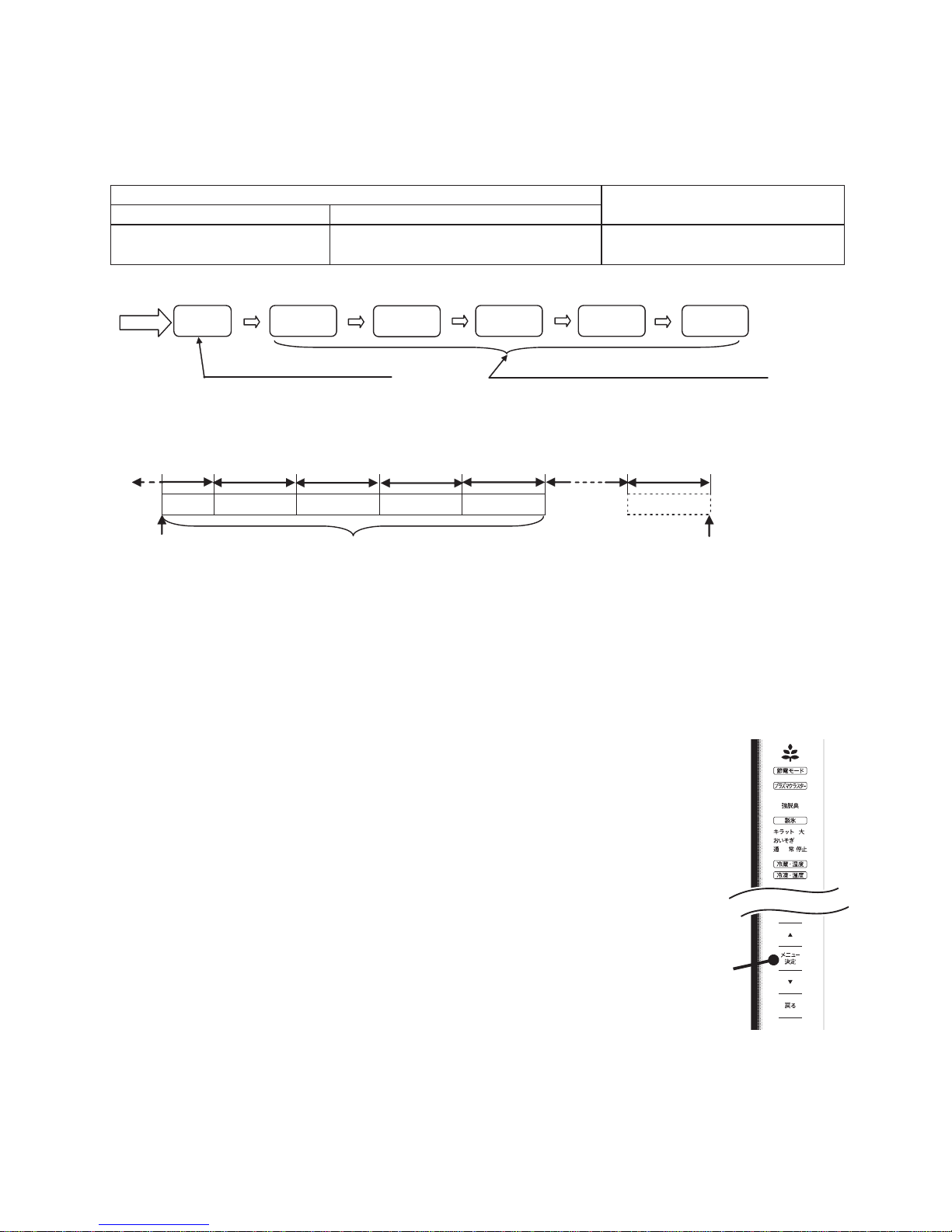
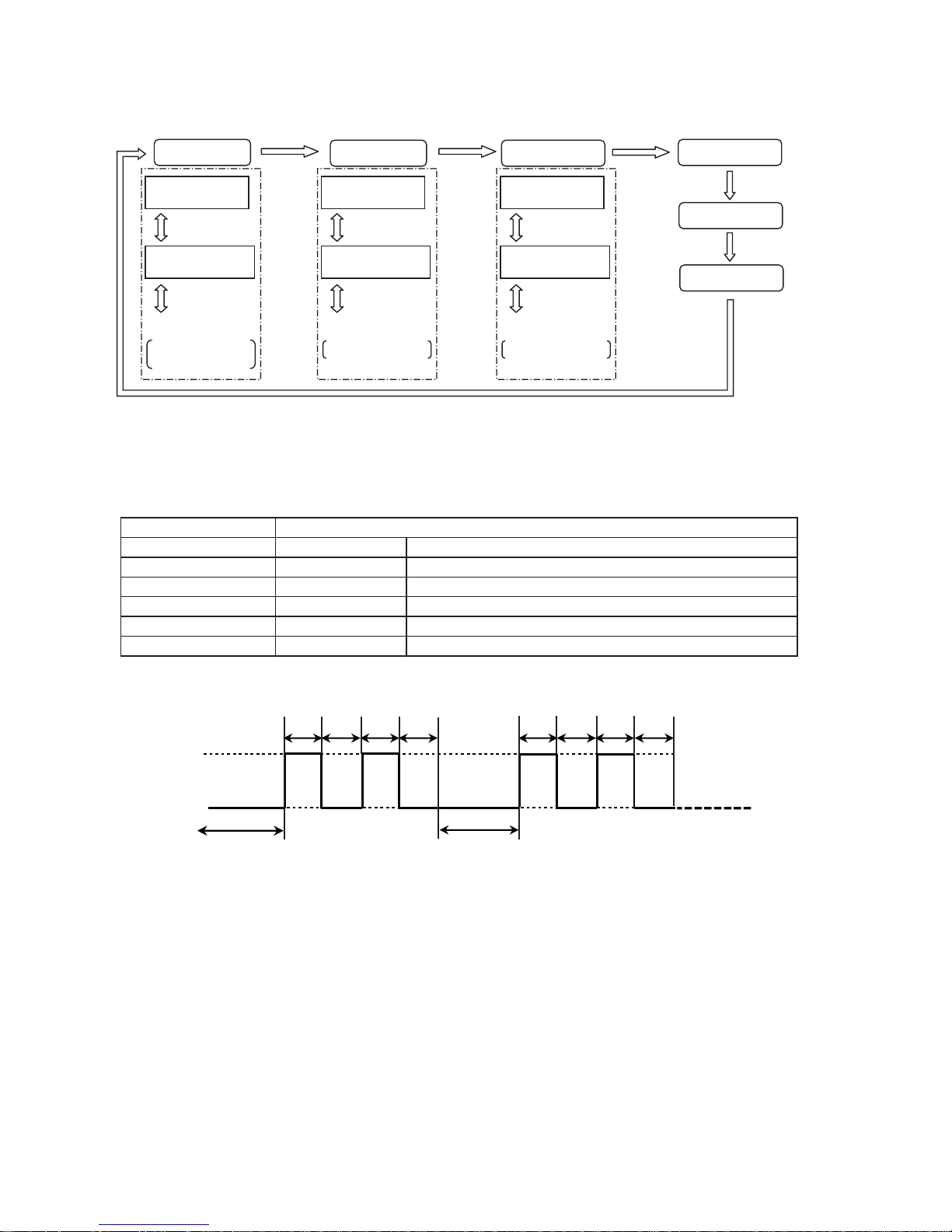
Outline1-1.
The self-diagnosis mode stores fault data for 5 days in the past (including “today”), and displays them by the date •
in the order of occurrence.
Self-diagnosis data to be displayed
Storage of self-diagnosis result
Current fault Fault history
All faults that have currently occurred
(Displayed in the order of fault number)
Faults that occurred in the past fi ve days
(Displayed by the date in the order of occurrence)
Storage of fault data for the past fi ve days
(Up to 9 items per day)
Self-diagnosis display•
Mode input
“Current”
fault display
“Today” fault
history display
“1-day before”
fault history display
“2-days before”
fault history display
“3-days before”
fault history display
“4-days before”
fault history display
Button
operation
Button
operation
Button
operation
Button
operation
Button
operation
Display priority is given to the upper stages
of self-diagnosis display (Table 1) (All items)
The last fault on that day is displayed first, and the older ones
are displayed in the order of occurrence. (Up to 9 items per day)
(Note 1) Self-diagnosis result data for 5 days (including “today”) are stored. 24 hours from the time when the
refrigerator power supply turned ON is defi ned as “one day”.
24 hours 24 hours 24 hours 24 hours 24 hours 24 hours
Today
Current time
1-day before 2-days before
Stored data
3-days before 4-days before
n-days before
Refrigerator power supply
is turned ON
(Note 2) How to clear stored data
After turning ON the power to the main unit, open the doors of the refrigerator compartment and the ice 1)
compartment within 2 minutes, and press and hold the [
戻る
] button for 5 seconds or longer.
With the doors of the refrigerator compartment and the ice compartment opened, press and hold the [2)
戻る
]
button for 5 seconds or longer again.
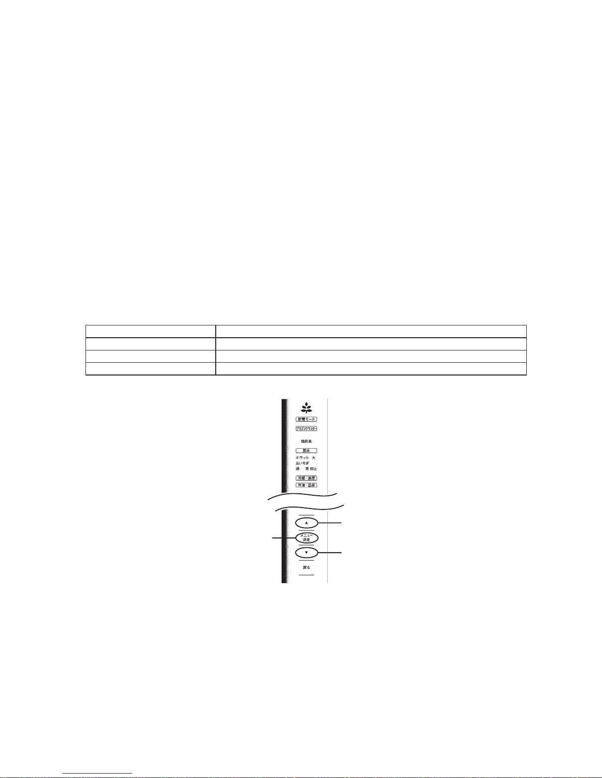
Self-diagnosis mode1-2.
Mode input method1)
With the refrigerator compartment door opened (the temperature control 1)
lamp unlit), press and hold the [
メニュー決定
] button for 5 seconds.
(The buzzer sounds, “beep, beep”.)
The refrigerator enters the self-diagnosis mode.
* The self-diagnosis mode will be automatically canceled when the status
with no button operation continues for 3 minutes.
* If the refrigerator does not enter the self-diagnosis mode, a fault with the
door switch system can be considered.
クリーン
[メニュー決定] button
Page 19
SJGF60XT
19
Operation in the self-diagnosis mode2)
The compressor is forcedly turned ON. (Excepting a period of defrosting operation and compressor ON delay •
time)
The cooling, condenser and R-fan motors are forcedly turned ON.•
(These motors will be forcedly turned ON even while the compressor is OFF. However, when the door is opened,
the motors other than the condenser fan motor are kept OFF.)
The refrigerator compartment/vegetable compartment PCI fan and the PCI are forcedly turned ON. (However, •
when the door is opened, the PCI and fan are kept OFF.)
When the refrigerator compartment door is opened, the R damper is forcedly closed. When the refrigerator •
compartment door is closed, the R damper is forcedly opened. (Opening/closing the refrigerator compartment
door activates the R damper operation.)
During execution of the self-diagnosis mode, and for 20 minutes after cancellation of this mode, self-diagnosis •
data serial output is executed.
During execution of the self-diagnosis mode, and for 20 minutes after cancellation of this mode, the door-open •
buzzer does not sound.
Operation during self-diagnosis mode, and self-diagnosis display3)
Self-diagnosis data is displayed on the temperature control panel. (Refer to self-diagnosis display [Table 1].)1)
Self-diagnosis display can be switched by operating the temperature control panel buttons.2)
Temperature control panel button Operation
[▼] Fault data for ward scroll
[▲] Fault data reverse scroll
[
メニュー決定
] Fault occurrence date for ward scroll
クリーン
Fault occurrence
date
(Forward scroll)
Fault data
(Forward scroll)
Fault data
(Reverse scroll)
Page 20
SJGF60XT
20
<Example of button operations and self-diagnosis display>
* During self-diagnosis mode input, the “current” fault is displayed.
・
・
・
・
・
・
・
・
・
[During mode input]
“Current” fault
Display of the fault
at the top of Table 1
Press [▲].
Press [▼].
Press [▲].
Press [▼].
Display of the fault at
the second top of Table 1
Display of all faults
that have occurred
Press
[メニュー決定].
Press
[メニュー決定].
Press
[メニュー決定].
“Current” fault history
Press
[メニュー決定].
Press
[メニュー決定].
Press
[メニュー決定].
Display of the
latest fault
Display of the
second latest fault
Press [▲].
Press [▼].
Press [▲].
Press [▼].
Press [▲].
Press [▼].
Press [▲].
Press [▼].
Display of up to 9 items Display of up to 9 items
“1-day before”
fault history
“2-day before”
fault history
Display of the
last fault
Display of the fault just
before the last
“3-days before”
fault history
“4-days before”
fault history
* During forward/reverse scroll of fault display with [▼]/[▼] button, if fault data to be displayed next does not exist,
the buzzer sounds “beep-beep”, and the display will not change.
* To display a fault occurrence date for currently displayed data, press the [
冷凍・温度
] lamp.
Fault occurrence date [
冷凍・温度
] lamp.
Current Unlit OFF
Toda y Li t O N
1-day before Blink once. Repeat "2-sec. OFF"/"0.5 -sec. ON/0.5-sec. OFF".
2-days before Blink twice. Repeat "2-sec. OFF"/"0.5-sec. ON/0.5-sec. OFF" twice.
3-days before Blink three times. Repeat "2-sec. OFF"/"0.5-sec. ON/0.5-sec. OFF" three times.
4-days before Blink four times. Repeat "2-sec. OFF"/"0.5-sec. ON/0.5-sec. OFF" four times.
Example of lamp indication: “2-days before”
0.5-sec. 0.5-sec. 0.5-sec. 0.5-sec. 0.5-sec. 0.5-sec. 0.5-sec. 0.5-sec.
2-sec. pause 2-sec. pause
Repeat
ON
OFF
Page 21
SJGF60XT
21
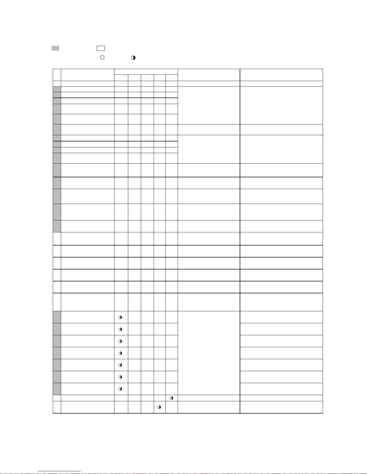
Self-diagnosis display [Table 1] 1-3.
(Problems and problem history related to thermistors, fan motors, auto ice cube maker, inverter,etc.)
- ○○○○○
○
○
--
1
○
2 ○
3 ○○
7
○○○
8
○
9
○○
10 ○○
11 ○○○
12
○○
14
○○○
15
○○○○
16
○
17
○○
18 ○○
19
○○○
-
20
○○
-
21
○○○
-
22
○○○
-
23
○○○○
-
24
○○
-
25
○
26
○
27
○○
28
○
29
○○
30
○○
31
○○○
32
-
33
-
Status
No.
ExplanationofStatuses
F-thermistor system problem
R-thermistor system problem
Def-thermistor system problem
There were two defrosted periods (defrosting
heater on time) that lasted for 120 min.
indicates a problem, indicates the status.
Fan motor g system problem
R fan motor system problem
Ice cube maker problems, wiring,
main pwb problems
Without trouble
Thermistor problems, thermistor
wiring short circuit and open
circuit, main pwb problems
A thermistor input value was short circuit
or open circuit.
Thermo. fuse or defrosting heater,
open circuit, main pwb problems
Ice cube maker thermistor
system problem
5
External air temperature
system problem*
Defrosting problem
Fan motor f system problem
Fan motor problems, fan lock,
wiring, main pwb problems
Sensor problems, sensor wiring
short circuit and open circuit,
main pwb problems
Description
Ice cube maker
forward operation error
The ice making position detection switch
was produced abnormal signal
at the time
forward operation.
of ice cube maker
Display communication
problem
Compressor revolution speed
abnormally low
Water tank out of water
The
Water tank
was out of water.
(Detection with thermistor)
Ice storage box full
The Ice storage box was full of ice cubes.
Lamp indication: Lit =
, Blinking = (0.5-sec. ON/0.5-sec. OFF)
Buzzer: Only when a fault is indicated in the current fault display, the buzzer continuously sounds (0.2-sec. ON/1.8-sec. OFF).
Lamp indication (Temperature control LED)
強
弱中
Refrigerator compartment
PCI fan motor fault
Humidity sensor problem
Refrigerator compartment
PCI power supply fault
Power supply clock fault
Ice cube maker
thermistor high temperature
F-thermistor high temperature
R-thermistor high temperature
R-thermistor low temperature
External air temperature
information
Door open information
Inverter wiring error
Inverter overload protection
Inverter startup fault
Inverter overcurrent
Inverter PWB communication
error
Inverter position detection fault
PCI fault, Wiring disconnection
Main PWB fault
Operation PWB or main PWB fault
Wiring fault
Main PWB fault
Compressor fault
Inverter PWB fault
Protector fault, Wiring fault
Main PWB fault
Detection of abnormal current value during
fan motor ON status
Detection of abnormal current value during
plasmacluster ON status
Error in communication with door operation PWB,
or communication between operation
microprocessor and touch IC
Detection of power supply clock signal
error in main PWB
Thermistor temperature is “-6ºC or higher”
continuously for 6 hours or longer.
F-thermistor temperature is “0ºC or higher”
continuously for 6 hours or longer.
R-thermistor temperature is “+10ºC or higher”
continuously for 6 hours or longer.
R-thermistor temperature is “lower than damper
closing temperature 5ºC” continuously for 2 hours
or longer.
External air temperature is “40ºC or higher”
continuously three times at external air
temperature data update timing.
Door open status has continued for 15 minutes
or longer, or door opening frequency is 200 times
or more/day.
The inverter microprocessor detected
a compressor wiring error.
The inverter microprocessor detected
compressor overload status.
The inverter microprocessor detected abnormal
drop of compressor rotation speed.
The inverter microprocessor detected
a compressor startup fault.
The inverter microprocessor detected overcurrent
in the compressor drive circuit.
Communication error between main
microprocessor and inverter microprocessor
The inverter microprocessor detected
a compressor motor position error.
* The external air temperature thermistor is located on the operation PWB.
Page 22

SJGF60XT
22
FORCED STOPPING OF DOOR ALARM BUZZER2.
* Used when the door switch is faulty.
How to stop
While the door-open buzzer sounds, press the [•
▼
] and [▼] buttons simultaneously and hold them for 3 seconds or
longer. (The buzzer sounds three times.)
Forced stopping is cancelled automatically 48 hours later.
THERMISTOR CIRCUIT CHECK METHOD3.
A thermistor is a semiconductor for which the resistance value changes as the temperature changes.•
This characteristic is used to allow the temperature to be read by a microcomputer.•
(Temperature Resistance value Changed to voltage.)
Check Method1-1.
Disconnect the connectors and measure the thermistor resistances.•
Determination Method1-2.
If the resistance[1] matches, there is a problem with the electronic circuit board.•
If the resistance[1] is different, there is a problem with the harness, connector, or thermistor.•
[ 1 ]
CN8 ⑫ー⑬
CN8 ⑭ー⑮
CN8 ー
CN10④ー③
CN8 ④ー⑤
27
25
CN10②ー③
Humidity sensor
Ice cubemaker thermistor
F-thermistor
DEF thermistor
R-thermistor
External air temperature
thermistor
Resistance Value
*1
(Ω)
pins pins
pins
pins
pins
pins
Voltage Value (V)
*2
*1. Disconnect connectors and measure the pins on the wiring side(Ω).
*2. Without disconnecting connectors, measure the voltage of the connector pins.(V).
(Note: Use a tester with a large internal impedance.)
Microcomputer
Connector
IC1
+
(A/D)
(On the circuit board)
+5V
[1]
Thermistor
[2]
Table of Thermistor Characteristics1-3.
[1]
- 30.0
- 25.0
- 20.0
- 15.0
- 10.0
- 5.0
0.0
5.0
10.0
15.0
20.0
25.0
30.0
35.8
26.1
19.3
14.4
10.9
8.3
6.4
5.0
3.9
3.1
2.5
2.0
1.6
[1]
- 30.0
- 25.0
- 20.0
- 15.0
- 10.0
- 5.0
0.0
5.0
10.0
15.0
20.0
25.0
30.0
35.8
26.1
19.3
14.4
10.9
8.3
6.4
5.0
3.9
3.1
2.5
2.0
1.6
[1]
- 30.0
- 25.0
- 20.0
- 15.0
- 10.0
- 5.0
0.0
5.0
10.0
15.0
20.0
25.0
30.0
83.9
61.2
45.2
33.7
25.5
19.5
15.0
11.7
9.2
7.3
5.8
4.7
3.8
- 30.0
- 25.0
- 20.0
- 15.0
- 10.0
- 5.0
0.0
5.0
10.0
15.0
20.0
25.0
30.0
[1]
F-thermistor
R-thermistor
DEF thermistor Humidity sensor
Ice cube maker
thermistor
External air
temperature thermistor
Temperature
Resistance
value
Temperature
Resistance
value
Temperature
Resistance
value
Temperature
Resistance
value
Voltage
value
(kΩ)
(°C)
(kΩ)
(°C)
(kΩ)
(°C)
(kΩ)
25.4
19.5
15.1
11.8
9.4
7.5
6.0
4.9
4.0
3.3
2.7
2.2
1.9
[1]
Resistance
value
(kΩ)
(°C) (V)
-
-
-
-
-
-
-
-
0
10
20
30
40
50
60
70
80
90
100
-
-
0.1
0.4
0.7
1.0
1.3
1.5
1.8
2.1
33.1
25.6
20.0
15.8
12.5
10.0
8.1
2.4
2.7
3.0
Temperature
(°C)
- 30.0
- 25.0
- 20.0
- 15.0
- 10.0
- 5.0
0.0
5.0
10.0
15.0
20.0
25.0
30.0
Temperature
(°C)
Page 23

SJGF60XT
23
INSPECTION FLOWCHART AND REPAIR ITEMS4.
During check of the PWB circuits, use thorough caution not to get electric shock.•
To check resistance of electric parts, be sure to disconnect the power supply plug. (Turn OFF the power supply.)•
Problem Self-diagnosis display Check/inspection point Action on error detection
Refrigerator does not
cool at al l
(The compressor
does not wo rk.)
F-ther mistor f ault 1) Conne ctor inse rtio n check ( Main PWB , interm ediate
connector)
2) Thermi stor res istanc e check (C heck the va lue in the
thermistor characteristic table.)
3) If the above c heck re sults are n ormal:
1) Correct t he insta llatio n.
2) Replace t he ther mistor.
3) Replace t he main PW B.
Invert er wirin g error 1) Inverter PW B – compr essor wi ring ch eck (Con nector
inser tion/ wire bre ak chec k)
2) If the above c heck re sults are n ormal:
1) Correct t he insta llatio n, or repla ce the wir ing.
2) Replace t he inver ter PWB or m ain PWB.
Invert er commu nicati on erro r 1) I nverter P WB – main P WB wiri ng check , Protect or chec k
(Conne ctor ins erti on/wi re break c heck)
2) If the above c heck re sults are n ormal:
1) Correct t he insta llatio n, or repla ce the wir ing/p rotecto r.
2) Replace t he inver ter PWB or m ain PWB.
Invert er overlo ad protec tion 1) Is there any pr oblem ab out the ref riger ator heat r adiatio n
space?
2) Compre ssor woun d wire res istanc e check ( Refer to pag e 13)
3) Refrige rant valve o perati on chec k
4) If the above c heck res ults are no rmal:
1) Improve the r efrige rator ins tallati on cond ition.
2) Replace t he comp ressor.
3) Replace t he refri gerant va lve or main P WB.
4) Replace t he invert er PWB or m ain PWB.
Invert er rotati on speed a bnorm al drop
Invert er star tup fault
Inverter overcurrent
Invert er posit ion detec tion fau lt
1) Compres sor wound w ire resi stance c heck (Re fer to page 13)
2) Refrige rant valve o perati on chec k
3) If the above c heck re sults are n ormal:
1) Replace th e compre ssor.
2) Replace t he refri gerant va lve or main P WB.
3) Replace t he inver ter PWB or m ain PWB.
F-ther mistor h igh-te mperat ure 1) Connecto r inser tion ch eck (Mai n PWB, int ermedi ate
connector)
2) Thermi stor res istanc e check (C heck the va lue in the
thermistor characteristic table.)
3) Compre ssor/f reezing c ycle che ck
4) If the above c heck res ults are no rmal:
1) Correct t he insta llatio n.
2) Replace t he ther mistor.
3) Replace t he comp ressor/ freezi ng cycle.
4) Replace t he invert er PWB or m ain PWB.
Cooling performance
is in suf fi cient
(The c ompres sor is
working.)
DEF ther mistor f ault
Exter nal air te mperatu re therm istor fau lt
1) Connecto r inser tion ch eck (Mai n PWB, int ermedi ate
connector)
2) Thermi stor res istanc e check (C heck the va lue in the
thermistor characteristic table.)
3) If the above c heck re sults are n ormal:
1) Correct t he insta llatio n.
2) Replace t he ther mistor.
3) Replace t he main PW B.
Coolin g fan moto r fault
Conden ser fan mo tor fault
1) Connecto r inser tion ch eck (Mai n PWB, int ermedi ate
connector)
2) Fan motor installation/condition/operation check
3) If the above c heck re sults are n ormal:
1) Correct t he insta llatio n.
2) Correc t the inst allati on, or repl ace the f an motor.
3) Replace t he main PW B.
Defros ting faul t 1) Connec tor inser tion check (Ma in PWB, in termedi ate
connector)
2) Defrost ing heat er resist ance ch eck (Che ck the valu e in the
functi onal par t specifi cations.)
3) If the above c heck re sults are n ormal:
1) Correct t he insta llatio n.
2) Replace t he defro sting hea ter or temp erature f use.
3) Replace t he main PW B.
Exter nal air te mperatu re infor mation
Door op en infor mation
1) Refriger ator inst allati on/oper ating co nditio n check
(Instal lation e nvironm ental tem peratu re, Door o pening /closin g
frequency)
1) Improve the i nstalla tion/op eratin g condit ion.
F-thermistor high temperature
No self- diagnosis faul t
1) F-therm istor co nnecto r inser tion che ck (Main P WB,
intermediate connector)
2) F-ther mistor re sistan ce chec k (Check t he value in t he
thermistor characteristic table.)
3) Coolin g fan motor o perati on chec k (Rotati on speed i s low.)
4) Condens er fan moto r operat ion chec k (Rotat ion spee d is
low.)
5) Compr essor an d freezin g cycle ch eck
6) Door packing inspection and installation/operating conditions
(Instal lation e nvironm ental tem peratu re, door op ening /closin g
freque ncy, too much s tuffe d food, etc .)
7) If the ab ove check r esults ar e norma l:
1) Correct t he insta llatio n.
2) Replace t he ther mistor.
3) Replace t he cool ing fan mot or.
4) Replace t he conde nser fan m otor.
5) Replac e the com presso r/free zing cycl e.
6) Improve th e packin g mountin g/ins tallati on/ope rating
condition.
7) Replac e the inver ter PW B or main PW B.
Freezer co mpartment
is too muc h coole d.
F-thermistor fault
1) Connecto r inser tion ch eck (Mai n PWB, int ermedi ate
connector)
2) Thermi stor res istanc e check (C heck the va lue in the
thermistor characteristic table.)
3) If the above c heck re sults are n ormal:
1) Correct t he insta llatio n.
2) Replace t he ther mistor.
3) Replace t he main PW B.
Page 24

SJGF60XT
24
Problem Self-diagnosis display Check/inspection point Action on error detection
Refrigerator
compar tment (chilled
case) is not c ooled
well
R-ther mistor f ault 1) Conn ector in sert ion chec k (Main PW B, inter mediate
connector)
2) Thermi stor res istanc e check (C heck the va lue in the
thermistor characteristic table.)
3) If the above c heck re sults are n ormal:
1) Correct t he insta llatio n.
2) Replace t he ther mistor.
3) Replace t he main PW B.
R-fan mo tor fault 1) Connector ins erti on chec k (Main PW B, inter mediate
connector)
2) Fan motor installation/condition/operation check
3) If the above c heck re sults are n ormal:
1) Correct t he insta llatio n.
2) Correc t the inst allati on, or repl ace the f an motor.
3) Replace t he main PW B.
R-thermistor high temperature
No self- diagnosis faul t
1) R-dampe r connec tor inse rtio n check (M ain PWB ,
intermediate connector)
2) R-damper installation/condition/operation check
3) R-ther mistor c onnect or inser tion c heck (Ma in PWB,
intermediate connector)
4) R-ther mistor re sistan ce chec k (Check t he value in t he
thermistor characteristic table.)
5) R-fan mo tor oper ation ch eck (Rot ation spe ed is low.)
6) Door pac king ins pectio n and installation/operating conditions
(Instal lation e nvironm ental tem peratu re, door op ening /closin g
freque ncy, too much s tuffe d food, blo ck of col d air supp ly port
at the bac k of the chil led cas e, suctio n port , etc.)
7) If the ab ove check r esults ar e norma l:
1) Correct t he insta llatio n.
2) Correc t the inst allati on, or repl ace the R- damper.
3) Correc t the inst allati on.
4) Replace t he therm istor.
5) Replac e the R-fa n motor.
6) Improve th e packin g mountin g/ins tallati on/ope rating
condition.
7) Replac e the main P WB.
Refrigerator
compar tment (chilled
case) is too m uch
cold.
R-ther mistor f ault 1) Conn ector in sert ion chec k (Main PW B, inter mediate
connector)
2) Thermi stor res istanc e check (C heck the va lue in the
thermistor characteristic table.)
3) If the above c heck re sults are n ormal:
1) Correct t he insta llatio n.
2) Replace t he ther mistor.
3) Replace t he main PW B.
R-ther mistor l ow temper ature 1) R-dampe r connec tor inse rtio n check (M ain PWB ,
intermediate connector)
2) R-damper installation/condition/operation check
3) If the above c heck re sults are n ormal:
1) Correct t he insta llatio n.
2) Correc t the inst allati on, or repl ace the R- damper.
3) Replace t he main PW B.
Ice mak ing failu re
Ice mak ing speed i s
low
Ice rel ease oper ation er ror 1) Conn ector ins erti on chec k (Main PW B, inter mediate
connector)
2) Ice maker ass’y installation/condition/operation check
3) If the above c heck re sults are n ormal:
1) Correct t he insta llatio n.
2) Correc t the inst allati on, or repl ace the ic e maker ass’ y.
3) Replace t he main PW B
Ice maker t hermi stor faul t 1) Connector in sert ion chec k (Main PW B, inter mediate
connector)
2) Thermi stor res istanc e check (C heck the va lue in the
thermistor characteristic table.)
3) If the above c heck re sults are n ormal:
1) Correct t he insta llatio n.
2) Replace t he ther mistor.
3) Replace t he main PW B.
Ice maker t hermi stor high t emperat ure 1) Connector in sert ion chec k (Main PW B, inter mediate
connector)
2) Thermi stor res istanc e check (C heck the va lue in the
thermistor characteristic table.)
3) Door pac king insp ectio n and installation/operating condition
check
4) If the above c heck res ults are no rmal:
1) Correct t he insta llatio n.
2) Replace t he ther mistor.
3) Improve the mounting/installation/operating condition.
4) Replace t he main PW B.
Ice str orage box i s full of ic e cubes 1) Ice sen sor oper ation ch eck (Chec k for con tact wit h the ice
storage box, etc.)
2) Ice maker a ss y installation/condition/operation check
3) If the above c heck re sults are n ormal:
1) Correct o r replac e the ice s ensor.
2) Correc t the inst allati on, or repl ace the ic e maker ass’ y.
3) Replace t he main PW B.
No water in w ater tank 1) Water tank wate r level and in stallat ion che ck
2) Water pump c onnect or inser tion ch eck (Mai n PWB,
intermediate connector)
3) Water pump installation/condition/operation check
4) Water pipe installation/condition check
5) Ice make r thermi stor res istanc e check (C heck the v alue in
the ther mistor c haract eristi c table.)
6) If the above c heck re sults are n ormal:
1) Replenish w ater into th e water tan k. Corr ect the
installation.
2) Correc t the inst allati on.
3) Correc t the inst allati on, or rep lace the wa ter pump.
4) Correc t the inst allati on.
5) Replac e the ther mistor.
6) Replace t he main PW B.
No self- diagnosis fault 1) Ice maker ass’y an d water pump o perati on chec k in ice tray
cleaning operation
2) Water pipe he ater resi stanc e check (app rox. 3.5 k)
3) Water pump/pipe installation/condition/operation check
4) If the above c heck res ults are no rmal:
1) Replace th e ice maker a ss’y or water p ump.
2) Correc t the con nector i nstall ation, or r eplace t he water
pipe heater.
3) Correc t the inst allati on, or rep lace the wa ter pump/ pipe.
4) Replace t he main PW B.
Page 25

SJGF60XT
25
PLASMACLUSTER OK/NG JUDGMENT5.
Judgment procedure1)
Disconnect the power supply, and keep the refrigerator compartment door opened for 5 minutes or longer to raise 1.
the temperature in the refrigerator compartment.
After closing the refrigerator compartment door, connect the power supply, and turn ON the plasmacluster. 2.
(When the plasmacluster is turned ON, the blue LED in the compartment and plasmacluster [
クリーン
] of control
panel on the door are ON.)
Check the ion at the PCI discharge port with the ion measuring instrument.3.
Refrigerator compartment: Measure PCI while pressing the door switch.
If at least either ion quantity (+ or -) is indicated, the judgment result is acceptable.4.
This procedure is intended for simplified check of fan motor and plasmacluster operations. Even if the ion •
quantity specified in the catalog cannot be confirmed, it is no problem. *
* Reason why the ion quantity specifi ed in the catalog cannot be confi rmed:
Because the ion quantity specified in the catalog has been measured in stable operating conditions with the •
refrigerator compartment door closed.
If the ion measuring instrument is inserted/removed when the compartment is cooled, condensation occurs with •
the measuring instrument, which disables reliable ion quantity check due to a measuring error.
Measuring position2)
During PCI operation
PCI measuring position
Refrigerator
compartment
Ice
compartment
Freezer
compartment
(Upper)
Freezer
compartment
(Lower)
Vegetable
compartment
Page 26

SJGF60XT
26
[8] DISASSEMBLY/ASSEMBLY
GENERAL DISASSEMBLY SEQUENCE1.
2-1-2
1-1
1-2
1-2
1-3
1-4
1-3
1-5
1-5
1-6
1-6
1-7
1-7
2-1
2-1-2
2-2
2-3
2-2
2-3
2-4
2-4
2-5
2-5
2-3-2
2-3-2
1-4
(1)
Refrigerator compartment
Accessories (Shelves・Chilled case・Water tank)
Partition support・C-shelf ass’y
Duct RT ass’y
R-shower duct ass’y
PCI box ass’y
R-C box ass’y・
Connector cover R
Pipe cover
(2)
Freezer compartment
Accessories
(Ice storage box・
Freezer cases)
SW cover
Ice maker ass’y T-SK
C-part. FI-B
C-part. FI-FK
(When replacing Proximity switch)
E.V cover ass’y
Heater・DEF thermistor holder
(When replacing F proximity switch)
Page 27

SJGF60XT
27
REFRIGERATOR COMPARTMENT DISASSEMBLY2.
Main component Contained parts
RC box ass’y Gear pump, R-thermistor, fan motor
Pipe cover -
R-shower duct ass’y Catalyzer
D-PCI box ass’y Plasmacluster unit, indicator PWB K-GF60X, D-fan motor PCI, Motor, O catalyzer
Remove the accessories (shelf, chilled case, etc.).1.
Remove the chilled shelf stopper.2.
Raise the back of the shelf slightly from the bottom,
and pull it to the front.
Chilled shelf stopper
C case cover
Freeset stay
How to remove freeset stay1)
Insert a thin fl athead screwdriver and push the entire
part toward the direction of arrow while twisting it to
take it off.
Freeset stay
How to remove C case cover2)
C-shelf ass’y (back side)
C case cover
(C-shelf ass
’y
with the C case cover attached)
Unhook three claws at the back and pull out the
protrusions in front.
Claws at the back
: Protrusion
C case cover
Installation is the reverse procedure to removal.•
How to remove chilled lock3)
Unhook two claws (if they are tight and stuck, insert
a thin flathead screwdriver (or a steel scale) to
unlatch them) and open the cover.
Remove one screw.
Claws
Chilled lock
Screw
Remove partition support l and partition stay.3.
Pull it while holding it up slightly.
Partition support l
Partition stay
Page 28

SJGF60XT
28
Remove duct RT rivet, and remove duct RT cover.4.
Pull it downward to raise it. (If it is stuck, insert a
fl athead screwdriver to raise it.)
Duct RT cover
Duct RT rivet
Remove the four locations of the inner protrusion.
When the protrusions are unhooked, pull it downward
to remove it.
: Protrusion
Remove R shower duct ass'y.5.
While holding the top by hand, pull the duct to the
front. (Claws are located at 8 places.)
: claw
R shower duct ass’y
Remove the D-PCI box ass'y.6.
Remove three screws.
P
ull the box downward to release the claws at the
front (at 2 places).
(The claws are directly applied to the food liner.
Use caution not to damage the food liner.)
After the claws are released, pull the box
downward, and release the remaining claws.
Disconnect two connectors.
□ : claw
○
: screw
D-PCI box ass’y
Remove the connector cover R (Screw at 1 place, 7.
Claws at 2 places), and disconnect four connectors.
Connector cover R
□ : claw
○
: screw
Remove the RC box ass'y.8.
Remove two screws, and pull the box to the front
while holding the top by hand.
Disconnect the joint pipe connected to the pipe
cover.
RC box ass’y
Joint pipe
Screw
Screw
CAUTION: Precaution for mounting the RC box ass'y
Make sure that the joint pipe is connected. Check for
twisting and lead wire entanglement.
Page 29

SJGF60XT
29
Pull out the pipe cover.9.
□ : claw
Pipe cover
FREEZER COMPARTMENT / ICE COMPARTMENT DISASSEMBLY3.
Main component Contained parts
Ice maker ass'y T-SK Ice maker thermistor, Ice maker ass'y, Ice cube heater, I-grill, Ice sensor, Ice cube maker
C-part. FI-FK Proximity switch
EV cover ass'y F-thermistor, DEF thermistor, Fan motor F
Heater DEF thermistor holder ass'y
(In vicinity of evaporator)
Thermo. fuse ass'y, DEF2 thermistor
Remove the accessories (cases and shelves of 1.
freezer compartment and vegetable compartment).
Remove the SW cover. •
(When replacement of F-LED PWB ass’y)
SW cover
Remove the Ice maker ass'y T-SK2.
.
Remove the screw and pull it toward you while 1)
pressing the claw on the front.
Remove connector.2)
Ice maker ass'y T-SK
□ : claw
Screw
Remove the damper.10.
Damper
CAUTION: Precautions for handling the ice maker ass'y T-SK
Securely insert the 4 claws. If the claws are not •
inserted completely and they come loose,the ice
maker ass'y T-SK could fall down during ice cube
release or it could sag down and make contact with
the ice storage box.
When connecting the connectors, make sure there •
are no connector insertion problems.
Remove the C-part. FI-B.3.
Remove the screw, and pushing the C-part. from
the left side to release the claw at the front.
Screw
C-part. FI-B
Claw
Page 30

SJGF60XT
30
Remove the C-part. FI-FK. •
(When replacement of F-LED PWB ass’y)
Remove three screws and one claw, and push the
PWB backward.
: screw
C-part. FI-FK
Open the connector cover at the left back 4.
(3 claws, one screw), and disconnect one connector.
Pull out the fl atter one between the two connectors.
□ : claw
Remove the EV cover ass'y.5.
Remove four screws.1)
Remove four claws at the top, and tilt the cover 2)
to the front.
○
: screw
EV cover ass’y
Top of the EV cover
□
: claw
EV cover ass’y
Remove the Heater. (Replacement procedure)6.
CAUTION: The heater is a charged and heating part.
Use caution about the following points:
Place the electric wiring and sleeve of the Heater •
at the specified positions. Make sure that they
will not touch the metal edges of the cooling unit,
heater cover, etc.
Be sure not to damage the piping of the cooling •
unit.
When connecting the connector, check for a •
connector insertion fault.
After replacement of the heater, check continuity •
and insulation.
When handling the heater, hold the rubber cap. Do
not touch the glass pipe with a bare hand. If you
touch the glass pipe, wipe grease off completely.
Pull the top of the evaporator to the front, and 1)
raise it slightly.
Pull out the evaporator obliquely.2)
Twist the straight pipe at the top of the accumulator •
so that the evaporator will not be deformed.
CAUTION
When pulling out the evaporator and bending •
the pipe, use caution so that the pipe will not be
broken or remarkably deformed.
Be careful not to get injury with the fins.•
Evaporator
Page 31

SJGF60XT
31
Remove the aluminum tape that fastens the lead 3)
wire to the drip tray.
Screw
Heater AL
Aluminum tape
Screw
Remove two screws, and remove the heater AL.4)
Open the heater fastening part of the heater AL to 5)
the right and left, and replace the heater.
Fastening part
Heater
Insert the lead wire in the groove of the drip tray, 6)
and apply the aluminum tape to fasten the lead
wire.
Lead wire
Aluminum tape
Groove of drip tray
Re-mount the evaporator in the original condition.7)
CAUTION
Put the bottom of the evaporator on the rib of the •
drip tray, and place the projection of the food liner
at the position shown in the figure.
Set the accumulator piping angle as shown in the •
figure.
Make sure that the pipe is not remarkably •
deformed.
Accumulator
Fastening part
HOW TO REMOVE OP. PWB ASS'Y4.
Insert a thin flathead screwdriver (or a steel scale) 1.
into the slot at the back of the PWB cover to unhook
the claws.
: claw
PWB cover
Remove the connector (1 place) and pull out the 2.
PWB.
Op. PWB ass'y
Connector
HOW TO REMOVE TERMINAL BOX5.
Remove screws (2 places).•
Terminal box
○
: screw
Page 32

SJGF60XT
32
HOW TO INSTALL R-SUB PACKING6.
Attach the R-sub packing sealer to the R-door L-ass'y only.1.
Provide a clearance so that the R-sub packing sealer will not protrude from the door packing.
(The hole edge is the reference position.)
Reference
Reference
Center
Center
Hole
Top enlarged view
Bottom enlarged view
Hole
R-sub packing sealer
R-sub packing sealer
R-door L-ass’
y
Fasten the R-sub packing with the claws of the R-door ass’y (front: 8 places, back: 6 places). First, claw either 2.
top or bottom of the packing to fasten it, and then claw the remaining points in sequence.
(The figure below shows R-door L-ass'y.)
: Claw
Make sure that a certain
clearance is provided so
that the R-sub packing
will not protrude from
the door packing.
Claw
R-sub packing
R-door packing
Page 33

SJGF60XT
33
HOW TO INSTALL DUCT RT ASS'Y COVER7.
Insert two claws (located in the center) of the Duct RT ass'y cover into the holders at the ceiling inside the 1.
refrigerator compartment.
2. After inserting two claws at the right and left side into the holders, tuck the Duct RT rivets into the holders.
①
①
②
②
(outside)
(Inside)
(outside)
* (Inside) will have a gap.
(Inside)
Duct RT rivet
Duct RT ass’y
With a Duct RT rivet inserted,
the claw of the Duct RT ass'y cover is spread apart
and held in place in the holder at the ceiling.
Duct RT rivet
<< Structural view of Duct RT rivet section >>
Duct RT rivet
After inserting the Duct RT rivets, confirm that
the head of the Duct RT rivet and the edge (outside)
of the depression of the cover are at the same height.
【How to remove Duct RT rivet】
There is a space at the back of a Duct RT rivet.
Insert a flathead screwdriver into the space
and pull out the rivet.
Page 34

SJGF60XT
34
ADJUSTMENT OF R-DOOR(DOUBLE DOOR)8.
If the right and left door positions are different:1.
Adjustment with the adjustable legs:
When the right door is lower than the left one, extend the adjusting legs on the right side•
(until the adjusting legs on the opposite side slightly leave the fl oor surface).
When the left door is lower than the right one, extend adjusting legs on the left side.•
If the door does not smoothly open/close2.
If the refrigerator is tilted backward, lay a wide pad on the back of the refrigerator.
Front
Back
Pad (wide)
If the door on the other side is also opened when the door on one side is opened:3.
Measure the clearance between the right and left doors of the refrigerator compartment, as the reference for 1)
adjustment.
Loosen the refrigerator compartment door lower hinge bolt, and slide the refrigerator compartment right door all 2)
the way to the outside.
With the door closed, slide the refrigerator compartment right door all the way to the inside until the closing failure 3)
can be corrected.
Tighten the lower hinge bolt by half to check opening/closing conditions. If there is no problem, tighten the bolt 4)
thoroughly. This completes the adjustment procedure.
If the refrigerator compartment door opening/closing problem persists even after the adjustment of Step 4), adjust 5)
the upper hinge of the refrigerator compartment right/left door. To widen the clearance between the doors, adjust
the upper hinge of the door that is relatively lower. (Use caution so that this adjustment does not cause a closing
failure.)
Check the opening/closing condition to ensure that there is no problem.6)
Refrigerator compartment
left door upper hinge: Adjustable
Refrigerator compartment
right door upper hinge: Adjustable
Refrigerator compartment
left door lower hinge: Not adjustable
Refrigerator compartment
right door lower hinge: Adjustable
<CAUTION>
Do not apply silicone oil to the center packing of the refrigerator compartment right and left doors. Oil fi lm is
generated between the center packing of the right and left doors, causing an opening/closing failure. (When one of
the refrigerator compartment doors is opened, the other door will also open.)
Page 35

SJGF60XT
35
MAIN PARTS ASSEMBLY9.
EV cover ass’y1)
<Components>
Fan louver A
A-sealer EV. cover C
A-sealer EV. cover A
A-sealer EV. cover E
L-band c
A-sealer
DEF-thermistor
Fan motor F
EV.cover
EV.cover AL
EV-insulation A
A-sealer EV. cover D
EV-insulation B
Fan louver B
EV.cover sealer N
A-sealer EV. cover B
F-thermistor
<Assembling procedure>
Attach the sealer to the fan motor F.1.
Attach the A-sealer to the fan motor F.•
10~40
Fan motor F
A-sealer
A-sealer
Fan motor F
Fan motor F
Start of sealing
No clearance or no overlapping
at the start and end of sealing.
Do not pinch the lead wire
with the seal material.
Sealing specifications
Page 36

SJGF60XT
36
EV-insulation A / EV-insulation B Assembly2.
• Attach the A-sealer EV. cover B and A-sealer EV. cover D.
• Fasten these parts with paper tape.
0~10
225
200
A-sealer EV. cover B
EV-insulation B
A-sealer EV. cover B
A-sealer EV. cover B
A-sealer EV. cover B
EVinsulation
A
EV-insulation B
A-sealer EV. cover D
A-sealer EV. cover D
EV-insulation B
EVinsulation
A
EVinsulation
B
Paper tape
Paper tape
Paper tape
Paper tape
Start of sealing
Paper tape
Paper tape
Overlapped
Overlapped
Apply tape along the edge.
Apply tape so that there is
no clearance between
EV-insulation A and B.
Start of sealing
Start of sealing
Apply tape along the edge.
Overlapped
Overlapped
Start of
sealing
Mounting the F-thermistor, fan motor F, and EV. insulation ass’y3.
• Fit the EV. insulation ass’y in the EV. cover.
• Wind the EV. cover sealer N on the F-thermistor.
• Mount the F-thermistor and fan motor F to the EV. cover.
EV-insulation ass’y
EV.cover sealer N
F-thermistor
EV.cover
Fan motor F
Apply the hook.
Wind the sealer on the lead wire,
and fit it in the rib.
Label is located on this side.
(Use caution about orientation.)
Page 37

SJGF60XT
37
Mounting the fan louver4.
• Mount the DEF-thermistor, and fasten the harness of the fan motor F and the DEF-thermistor with the L-band C.
• Wind the EV. cover sealer N on the lead wire of the DEF-thermistor and the fan motor F.
• Apply the EV. cover AL.
• Mount the fan louvers A and B to the front, and fasten them with two screws.
• Attach the A-sealer EV. covers A, C and E as shown in the fi gure.
• Insert the pins into the connectors.
Fan louver A
EV.cover
A-sealer EV. cover C
A-sealer EV. cover E
A-sealer EV. cover E
EV.cover
EV. cover AL
A-sealer EV. cover A
Fan louver A
EV.cover
L-band C
EV.cover sealer N
DEF-thermistor
Fan motor F
Fan louver A
Fan louver B
Overlapped
Fan louver on
the back face
Overlapped
Apply the sealer to both
fan louver A and EV. cover.
Wind the sealer on the lead wire,
and fit it in the groove.
Cut out a surplus part.
Start of sealing
Overlapped
Viewed in direction of arrow A
Front view
Screw
Screw
Connector pin insertion specifications
Nos. 1, 2 and 3 connector pins
are already inserted.
Insert the lead wire
to the connector.
Blue
Blue
White
White
Fan motor F connector
DEF-thermistor lead wire
F-thermistor lead wire
Insert the lead wire
to the connector.
Page 38

SJGF60XT
38
R-shower duct ass’y2)
<Components>
R-shower duct cover T
R-shower duct cover B
R shower duct insu
A-sealer R-S duct C
A-sealer R-S duct B
Catalyzer
Cool plate
Center cover L
Center cover R
<Assembling procedure>
Attach the A-sealer R-S duct B to the R-shower duct cover T.1.
Attach A-sealer R-S ducts C to the R shower duct insu.2.
R shower duct insu
R shower duct insu. sealing specifications
A-sealer R-S duct B
A-sealer R-S duct B
A-sealer R-S duct C
Put the A-sealer R-S duct B
on so that it comes to the top.
R-shower duct cover T
R shower duct insu
A-sealer R-S duct C
A Arrow view
A
A
A
R-shower duct cover T
A-A Cross-sectional view
Page 39

SJGF60XT
39
Mount R-shower duct covers B to the cool plate. (Apply the claw securely.)3.
Insert the R shower duct insu. of Step 2 in the cool plate of Step 3.4.
Mount the center covers L and R. (Apply the claw to the insulation securely.)5.
Insert the catalyzer.6.
R-shower duct cover
R-shower duct cover B
Catalyzer
Apply the hook
to the R shower duct insu.
Insert the catalyzer
with the claws spread out.
R shower duct insu
Claw
Center
cover L
Center
cover R
Cool plate
R shower duct insu
Apply the hook
to the R shower duct insu.
Apply the hook
to the R shower duct insu.
Apply the hook
to the R shower duct insu.
Page 40

SJGF60XT
40
RC box ass’y3)
<Components>
A-sealer R-FM-S
Fan motor
A-sealer RCBOX A
A-sealer RCBOX B
Packing holder
Joint pipe
Joint packing
Gear pump
R-C box
R-thermistor
R-C box insu.B
R-C box insu.A
<Assembling procedure>
Insert the joint packing in the gear pump.1.
Mount the joint packing vertically.•
Joint packing
Gear pump
Mount the assembly of Step 1 to the R-C box.2.
Make sure that the joint packing is securely fit in the support part.•
Gear pump
Joint packing
R-C box
Support part
Page 41

SJGF60XT
41
Fasten the packing holder to the assembly of Step 2 with two screws.3.
Tightening torque is 3.5 to 4.5 kgf/cm (0.34 to 0.44 Nm).•
Insert the gear pump harness in the groove of the R-C box, and bend the R-C box hinge so that the Claw is •
securely engaged.
Attach the gear pump harness inserted in the R-C box groove to the Claw of the R-C box securely.•
Screw
Screw
Packing holder
Hinge
En
gag
e the hook.
Groove of R-C bo
x
Attach the harness to the hook.
Insert the joint pipe to the gear pump.4.
Insert securely.•
Attach the joint pipe vertically as shown the figure.•
Mount the R-thermistor to the R-C box.5.
Gear pump
R-thermistor
Attach the harness
to the hook.
Paper tape
Attach the joint pipe vertically
Joint pipe
Attach A-sealer R-FM S to the fan motor, and mount it to the R-C box insu. A.6.
0~ 2
A-sealer R-FM S
Fan motor
A-sealer R-FM S
R-C box insu.A
Butt
Label is located on this side.
(Use caution about orientation.)
Page 42

SJGF60XT
42
Insert the R-C box insu. B in the assembly of Step 6, and fasten it with tape.7.
Insert the R-C box insu. B securely to the innermost position, and fasten it with two pieces of paper tape •
(width: 30 mm)
R-C box insu.A
Fan motor
R-C box insu.B
R-C box insu.A
R-C box insu.B
Paper tape (width: 30 mm)
Attach the A-sealer RCbox A and RCbox B to the assembly of Step 7.8.
Attach the sealer securely so that it will not rise.•
15 20
A-sealer RCbox A
R-C box insu.A
A-sealer RCbox A
R-C box
insu.A
A-sealer RCbox A
R-C box
insu.A
A-sealer RCbox B
R-C box insu.B
A-sealer RCbox B
R-C box insu.A
A-sealer RCbox A
A-sealer RCbox B
A-sealer RCbox B
R-C box
insu.B
R-C box insu.A
A-sealer RCbox A
A-sealer RCbox B
Start of sealing
Start of sealing
Overlapped
End of sealing
Start of sealing
Sealing reference position
Start of sealing
Paper
tape
Overlapped
Attach sealer
so that the groove
is securely sealed.
End of sealing
Fold the sealer inward.
A-A
cross-section
B-B
cross-section
AA
BB
Mount the assembly of Step 8 to the assembly of Step 5.9.
Claw
Claw
Page 43

SJGF60XT
43
C-part. FI-FK4)
<Components>
C-part.FI-FL
A-sealer FI
C-part. FI-FR
Proximity switch
C insu. FI
A-sealer FIA
A-sealer FIC
A-sealer FIB
<Assembling procedure>
Put the A-sealer on the C insu. FI.1.
Put it on so that there is no space between the sealer and the insulation.
Start of sealing
Start of
sealing
A-sealer FI
A-sealer FI
A-sealer FI
C insu. FI
C insu. FI
Lap over
20~60
Attach the proximity switch to the C insu.FI-FL.2.
Paper tape (20×15)
Hook the claw.
Twist the harness twice
around the boss
Proximity switch
C-part.FI-FL
Page 44

SJGF60XT
44
Mount the assembly of Step 1 to the assembly of Step 2.3.
C-part.FI-FL
C insu.FI
Attach the C-part. FI-FR to the assembly Step 3 and screw it on.4.
Put the A-sealer FIA, B and C.•
A-sealer FIA
A-sealer FIA
A-sealer FIC
A-sealer FIB
A-sealer FIB
A-sealer FIB
Sealing standard
Sealing standard
Sealing standard
Hook the claw
Hook the claw
Hook the claw
Hook the claw
C-part.FI-FR
C-part.FI-FR
C-part.FI-FR
C-part.FI-FL
C-part.FI-FL
C-part.FI-FL
Page 45

SJGF60XT
45
D-PCI box ass’y5)
<Components>
Indicator PWB K-GF60X
A-sealer D PCI box A
A-sealer PCI fan
D-fan motor PCI
Plate
D-damper holder
Plasmacluter unit
D-damper flap
A-sealer d-damper B
O catalyzer
A-sealer d-damper A
D-PCI cover
D-PCI box ass’y
Absorbent rubber B
Absorbent rubber A
Motor
<Assembling procedure>
Attach A-sealer PCI fan and paper tape.1.
Attach A-sealer PCI fan to the D-fan motor PCI.•
3~10mm
A-sealer PCI fan
A-sealer PCI fan
D-fan motor PCI
D-fan motor PCI
Doubled
No protrusion from discharge port
as reference position.
Sealing start position
Paper tape
To plasmacluster unit
To indicator PWB ass’ y
After Clawing the wire,
attach paper tape.
Plate
Page 46

SJGF60XT
46
Attach A-sealer D-damper A and B.2.
Attach A-sealer D-damper A and B to the D-damper flap.•
D-damper flap
A-sealer d-damper B
A-sealer d-damper A
D-damper flap
When attaching A-sealer D-damper B,
do not cover the rib of the D-damper flap
periphery.
When attaching A-sealer D-damper A,
do not cover the rib of the D-damper flap
periphery.
Mount the assembly of Step 2 to the D-damper holder.3.
D-damper flap
D-damper flap
D-damper flap
D-damper holder
Motor
Screw
(Check the looseness of the screw.)
Screw
(Check the looseness of the screw.)
Fit the projection of the D-damper flap
in the hole of the D-damper holder.
Fit the projection of the motor
in the hole of the D-damper flap,
and fasten it with the screw.
Mount the assembly of Step 1, D-PCI cover, O-catalyzer, absorbent rubbers A and B, Indicator PWB and 4.
Plasmacluster unit to the D-PCI box ass’y.
The projection of absorbent rubber A is fit
in the hole of the D-fan motor PCI.
Indicator PWB
O-catalyzer
Absorbent
rubbers A
Absorbent
rubbers B
Plasmacluster unit
Absorbent
rubbers A
Absorbent
rubbers B
D-PCI box ass’y
D-fan motor PCI
D-PCI cover
Page 47

SJGF60XT
47
Mount the assembly of Step 3 and the D-PCI fan cover to the assembly of Step 4, and attach A-sealer PCI box.5.
A-sealer D-PCI box A
A-sealer D-PCI box A
A-sealer D-PCI box A
A-sealer PCI fan
D-fan motor PCI
A
A-sealer D-PCI box A
A-sealer PCI fan
A-sealer D-PCI box A
Put it on so that
the A-sealer D-PCI box A
overlaps the A-sealer PCI fan.
Hook the claw on
the D-PCI box
to the D-PCI cover
(at 1 place).
D-PCI box ass’y
D-PCI cover
Attach A-sealer D-PCI box in the range of A.
Do not deform the sealer by stretching it excessively.
Hook the claw on
the D-PCI box
to the D damper holder
(at 2 places).
Hook the claw on
the D-PCI box
to the D-fan motor PCI
(at 3 places).
Page 48

SJGF60XT
48
Ice maker ass’y T-SK6)
<Components>
Plate
Ice cube maker
Ice cube tray AT
Thermistor
Thermistor cover
Sealer
Ice cube heater
Ice heater cover T
I-grill
Harness cover
Ice maker ass’y
Ice senser
L-band C
<Assembling procedure>
Put Thermistor on back side of Ice cube tray AT. 1.
Pu• t Selar on Thermistor, cover them with Thermistor cover and fix by 4 claws and square holes.
Place the Sealer on the Thermistor, and put the Thermistor cover over it and fix it with four claws•
(square holes, round protrusions).
Ice cube tray AT
Ice cube tray AT
Thermistor
Thermistor
Thermistor cover
rib
rib
Set the rib between
the 2 lead wires.
Sealer
claw
square hole
Insert the ice cube heater along the groove of the ice cube tray AT.2.
Attach it without twisting the heater so that the mark can be seen around the entire circumference.•
Ice cube tray AT
The marking existence side
Put it well.
Align the end face of
the protective tube with the rib.
Align the end face of
the mold with the rib.
Attach the end face of
the protective tube to the boss.
How to install the ice cube maker
(Figure of back side)
Mark of Ice cube heater
1.5
凸0.2
Loosen.
Ice cube heater
Page 49

SJGF60XT
49
Cover Ice cube tray AT with Ice heater cover T.3.
* Set Ice heater cover T so as to "
" marking side is on axis of Ice cube tray AT.
* Tightening toruque is 0.5N•m.
Ice cube tray AT
Ice heater cover T
Screw
Marking “ ”
Axis
Put rib of Ice senser in groove of ice maker ass'y, and fi x Ice senser to Ice maker ass'y by tapping screw.4.
* Put head of Ice senser points fi nal gear of Ice maker ass'y.
* Use jig to prevent variability fi xing Ice senser.
* Tightning torque is 0.5N m.
Screw
Ice maker ass’y
Ice maker ass’y
Final gear
Move this direction
(remove backlash)
Groove
Rib
Head
Ice senser
Insert the assembly of Step 3 to the assembly of Step 4.5.
Make sure that the ice cube tray AT is attached in the right direction. •
(The ice making section comes to the mounting foot side of the ice maker ass'y)
Insert it all the way inside the fi nal gear so that it fi ts fi rmly. •
Ice cube tray AT
Ice maker ass’y
Page 50

SJGF60XT
50
Get the harness of the ice make thermistor in the assembly Step 5 through the holes in front of and at the back 6.
of the I-grill.
Make sure to keep the end face of the protective tube next to the ice cube tray covered with the ice heater cover T.•
(Do not pull the harness strongly.)
I-grill
Ice cube tray AT
harness(heater)
harness(heater)
Ice maker ass’y harness
hole A (front side hole)
hole B (back side hole)
Set the assembly Step 6 to I-grill.7.
Put the axis of the ice cube tray slightly into the hole of the I-grill. While releasing the front stopper, turn around •
the front side of the harness of the ice maker ass'y so that it can be inserted into the hole of the I-grill.
After it is inserted, make sure to confi rm that the stopper is securely in place.•
Confi rm that the tip of the ice sensor is in the release hole.•
Make sure that there is at least 2.5mm space between the tip of the ice sensor and the release hole.•
harness of
Ice maker ass’y
Legs of Ice
maker ass’y
axis of Ice cube tray AT
,
hole C (I-grill)
hole E (to release Ice senser)
hole D
more than 2.5mm
back side
front side
Stopper
clearance
clearance
Connet socket contact of thermistor to Ice cube maker ass’y to connector housing.8.
Check socket contact is securely inserted.•
After inserting Socket contact, insert plate to Socket contact securely.•
Plate
After inserting
Plate
Socket contact
Claw
Connector housing (white)
Hole No.5, No6
Page 51

SJGF60XT
51
Bundle the harness with the L band C and fix it to the I-grill.9.
(1) Bundle the ice maker thermistor and the protective tube of the ice cube heater with the L band C and fi x them to
the I-grill.
Align the end face of the protective tube, and tie the L band C up at the front of the marking (black band) of the ice •
heater cover T.
(2) Fix the ice maker ass'y and the harnesses of the ice maker thermistor and ice cube heater with the L band C.
Make sure that the harnesses of the thermistor and heater are not too loose.•
L band C
Make sure that protective tube is covered by the heater cover.
L band C
I-grill
55±5
Marking of the ice heater
(2)
(1)
Fix the harness cover to the I-grill with screws.10.
Make sure that the ice maker ass'y does not pinch the harnesses.•
Screw
Harness cover
Page 52

SJGF60XT
52
Fruit case ass'y7)
<Components>
Fruit case
K handle base
K handle arm
K handle cover
K handle cover label
K handle support
K lock rever
K lock spring
K handle
Lock unit
<Assembling procedure>
Install the K handle arm and K lock rever to the K handle base.1.
K handle base
K lock rever
K handle arm
Install the K lock spring to the K handle support.2.
K lock spring
K handle support
Page 53

SJGF60XT
53
Combine assembly Step 1 and Step 2. Insert the claw A to the form B firmly.3.
Confi rm that the tip of the K lock spring is inserted into the cross rib of the K lock lever.
K lock spring
Claw A
Claw A
Form B
K handle base
K lock rever
K handle support
Align the K handle cover assembly Step 3. Make sure to insert three claws properly.4.
K handle cover
Three claws
Bring down the K handle arm while pushing the K lock lever in assembly Step 4.5.
K lock rever
K handle arm
Page 54

SJGF60XT
54
Hook assembly Step 5 to the fruit case and rotate it. Be careful not to scratch parts against others.6.
Fruit case
Put the dent of K handle base from the bottom
to the convex of fruit case.
Hook two claws on the K handle base to the fruit case. Make sure to insert them properly.7.
Fruit case
K handle base
Two claws
Make sure to insert the K handle into three claws on the K handle arm properly.8.
K handle
Three claws
K handle arm
Fruit case
Page 55

SJGF60XT
55
Fan motor G ass’y8)
<Components>
W-sealer-g fan
Fan motor G
W-sealer-g fan
W-sealer-g fan hnss
<Assembling procedure>
Attach the W-sealer G fan to the fan motor G.1.
When attaching the W-sealer G fan, do not stretch it strongly.•
Attach the W-sealer G fan harness.2.
Pull the harness tube of the fan motor G to the connector side, and attach the W-sealer G fan harness to the tube.•
15 15
30 30
30 30
40
15 15
3030
30
1515
1515
30
220.5
W-sealer-g fan
W-sealer-g fan
W-sealer-g fan
W-sealer-g fan
Fan motor G
W-sealer-g
fan hnss
W-sealer-g
fan harness
With the harness pulled to the connector side,
attach the W-sealer G fan harness.
Attach the W-sealer G fan harness
while winding it on the harness.
A-A cross-section
A
A
Page 56

PartsGuide
SJGF60XT
PARTS LIST
Refrigerator-freezer
MODEL
SJ-GF60X-T
[1] SJ-GF60X-T DOOR
[2] SJ-GF60X-T CABINET1
[3] SJ-GF60X-T CABINET2
[4] SJ-GF60X-T CABINET3
CONTENTS
[5] SJ-GF60X-T CYCLE
[6] SJ-GF60X-T OTHER PARTS
INDEX
This document has been published to be used
for after sales service only.
The contents are subject to change without notice.
Page 57

SJGF60XT
3-12
3-15
3-15
3-17-2
3-17-3
3-18
3-17
3-17-1
5-5
5-24
5-25
5-22
5-23
5-23
5-12
5-17
5-7
5-6
5-8
5-16
5-38
5-39
5-40
3-28
5-1
5-2
5-35
5-36
3-19
3-24
3-1
5-14
3-4
3-20
3-25
3-21
5-9
5-42
5-21
5-41
5-10
5-18
5-13
5-37
3-3
5-19
3-7
3-7
3-22
3-6
3-10
3-10
3-5-2
3-5-1
3-23
3-9
3-8
3-5-1
3-5-3
3-5
3-5-2
5-15
3-32
3-32
3-31
3-33
3-30
5-21-5
5-21-3
5-21-1
5-21-2
5-16-1
5-16-2
5-21-4
5-21-6
5-21-7
5-20
5-33
5-26
1-3
3-40
3-39
3-8-3
5-3
1-3-2
3-2
3-35
3-37
3-13
3-11-2
3-11-3
3-11
3-11-1
5-21-11
5-11
[1] SJ-GF60X-T DOOR
2
Page 58

NO. PARTS CODE
PRICE
RANK
NEW
MARK
PAR T
RANK
DESCRIPTION
[1] SJ-GF60X-T DOOR
1-3 DPWB-A307CBKZ BE Op. Pwb ass'y
1-3-2 LHLD-A982CBFA AF Op. Pwb holder
3-1 DFRM-A133CBKZ AY F-frame ass'y
3-2 FDORFC366CBKZ BS F-door ass'y
3-3 PPACGA340CBZA AK F-sub packing
3-4 PPACGA341CBZA AH F-sub packing
3-5 DFRM-A134CBKZ AV F-t frame ass'y
3-5-1 LFRM-A457CBTA AN Fi frame l
3-5-2 LFRM-A458CBTA AN Fi frame r
3-5-3 LFRM-A459CBFA AE F-t frame-b
3-6 FDORFC367CBKZ BH F-t door ass'y
3-7 PPACGA342CBZA AG M-sub packing
3-8 DFRM-A146CBKZ AW I-frame ass'y
3-8-3 LFRM-A488CBFA AE I-frame b
3-9 FDORIA200CBKZ BF I-door ass'y
3-10 PPACGA300CBZA AE I-sub packing
3-11 FDORRC702CBKZ BX R-door r ass'y
3-11-1 MSLI-A141CBFA AE Door cam r-bottom
3-11-2 LSTPPA136CBFA AC Stopper spring tr
3-11-3 MSLI-A139CBFA AD Door cam r-top
3-12 FPACGA694CBZA AZ R-door r packing
3-13 HBDGBA005CBZB AE Pci badge
3-15 PPACGA378CBZA AM R-sub. Packing
3-17 FDORRC701CBKZ BR R-door l ass'y
3-17-1 MSLI-A142CBFA AE Door cam l-bottom
3-17-2 LSTPPA141CBFA AC Stopper spring tl
3-17-3 MSLI-A140CBFA AD Door cam l-top
3-18 FPACGA693CBZA AX R-door l packing
3-19 GCOVPA336CBFB AE Pwb cover
3-20 DFRM-A148CBKZ BA V-frame ass'y
3-21 FDORVA992CBKZ BS V-door ass'y
3-22 FPACGA564CBFA AX F-t door packing
3-23 FPACGA546CBFA AK I-door packing ass'y
3-24 FPACGA565CBFA AZ
3-25 FPACGA566CBFA AZ V door packing
3-28 PSEL-E226CBZZ AA Sealer
3-30 PSEL-E856CBZZ AE A-sealer f-t ddor
3-31 PSEL-E252CBZZ AB A-sealer fi d liner
3-32 PSEL-E253CBZZ AC A-sealer f door liner
3-33 PSEL-E855CBZZ AD A-sealer
3-35 PSEL-E739CBZZ AD A-sealer r door r-b
3-37 PSEL-E361CBZZ AD A-sealer r door l-b
3-39 PSEL-E582CBZZ AB Sub packing sealer
3-40 PSEL-E753CBZZ AB Sub packing sealer T
5-1 DTNA-A230CBKZ AR Free set shelf ass'y
5-2 FTNA-A650CBKZ AP Free set shelf ass'y
5-3 DTNA-A235CBKZ AY R shelf ass'y
5-5 UTNAPA050CBFA AE Egg tray 10a
5-6 UYOK-A667CBFB AM Egg case
5-7 LSTYPA063CBFA AK Partition support l
5-8 LSTYPA064CBFA AK Partition stay
5-9 PCOV-A471CBFA AN Moisture cover
5-10 PSHEPA104CBZZ AE Noise-proof sheet
5-11 PSRA-A083CBFA AD Ice scoop
5-12 FTNA-A687CBKZ AX C-shelf ass'y
5-13 UYOK-A722CBWZ AR F case sus
5-14 UYOK-A695CBFB AZ F bottom case
5-15 UYOK-A696CBFC AX F top case
5-16 FYOK-A353CBKZ AX Chilled case ass'y
5-16-1 UYOK-A771CBFA AR Chilled case
5-16-2 GWAKPA470CBRA AQ Chilled case frame
5-17 UYOK-A671CBFB AL Case
5-18 UYOK-A733CBFA AP Ice storage box
5-19 UYOK-A723CBFB AR F case s
5-20 UYOK-A734CBFA AZ Vegetable case
5-21 FDAI-A147CBKZ AR Lock unit
5-21-1 GDAI-A114CBFA AE K handle base
5-21-2
5-21-3 JHNDPA356CBFA AF K handle arm
5-21-4 LPLTPA667CBFA AD K handle cover
5-21-5 LPLTPA668CBFA AE K handle support
5-21-6 MLEVPA025CBFA AC K lock rever
5-21-7 MSPRDA002CBZZ AB K lock spring
5-21-11 TLAB-C617CBRA AC K handle cover label
JHNDPA355CBFA AD K handle
5-22 UPOKPA354CBFC AQ Bottle pocket
5-23 UPOKPA355CBFC AK Door pocket
5-24 UPOKPA356CBFC AN Bottle pocket l
5-25 UPOKPA344CBFC AK Door pocket
5-26 UYOK-A705CBFB AP Pet case
5-33 UYOK-A735CBWZ AT V case sus
5-35 DTNA-A233CBKZ AV Free set shelf ass'y
5-36 FTNA-A652CBKZ AR Free set shelf ass'y
5-37 UYOK-A785CBWZ AP C case tray
5-38 PCOV-A514CBFA AN C case cover
5-39 LSTYPA071CBFA AK Freeset stay
F-door packing
SJGF60XT
3
Page 59

SJGF60XT
NO. PARTS CODE
PRICE
RANK
NEW
MARK
PAR T
RANK
[1] SJ-GF60X-T DOOR
5-40 PPACGA387CBFA AF C case packing
5-41 UYOK-A768CBFA AW Fruit case
5-42 FYOK-A352CBKZ BA Fruit case ass'y
DESCRIPTION
4
Page 60

2-20
2-21
2-18
2-19
2-10
2-10
2-12
4-3
4-3
4-6
2-8
2-13
2-9
4-2
4-7
4-7
2-104
2-105
4-4
4-10
2-101
2-16
2-17
4-10
2-90
2-101
4-9
1-31
2-83
1-23
2-84
2-86
2-85
2-87
2-100
2-15
2-106
2-14
4-4
4-9
2-26
2-3
4-4
4-4
2-88
1-24
2-1
2-23-2
2-23-4
1-7
2-23-5
2-23
2-23-3
2-24
2-22
2-138
2-25
1-8
2-140
2-145
5-4-1
5-4
5-4-2
5-4-3
5-4-4
5-4-6
5-4-5
4-1
2-93
2-93
4-1
1-26
1-26
2-120
2-121
2-81
2-80
2-2
4-1
4-1
4-1
2-147
4-15
2-117
2-117
2-118
2-119
2-11
2-114
[2] SJ-GF60X-T CABINET1
SJGF60XT
5
Page 61

SJGF60XT
NO. PARTS CODE
PRICE
RANK
NEW
MARK
PAR T
RANK
DESCRIPTION
[2] SJ-GF60X-T CABINET1
1-7 RH-HXA154CBZZ AM Thermistor
1-8 RHETBA384CBZZ AZ Ice cube heater
1-23 QSW-LA031CBZZ AK Proximity switch
1-24 FACC-A176CBKZ BD Source cord-k
1-26 QSW-PA079CBEA AH Door switch
1-31 RDTC-A001CBZZ AP Humidity sensor
2-1 ZPAPRBPCOVERY AB Back p cover
2-2 FSRA-A308CBKZ AL Eva-pan assy'
2-3 GCOV-A405CBPZ AQ Comp. Cover
2-8 FCABCA747CBYZ AQ C-plate rf ass'y
2-9 FCABCA749CBYZ AL Center plate fv
2-10 FAJS-A034CBKZ AE Adjustable leg ass'y
2-11 FLEGPA166CBYZ AH Leg holder l ass'y
2-12 FLEGPA168CBYZ AH Leg holder r ass'y
2-13 FCABCA750CBYZ AP Center plate fv
2-14 FHNG-A245CBYZ AR Upper hinge l ass'y
2-15 MSLI-A147CBFB AE Hinge cam lt
2-16 FHNG-A246CBYZ AR Upper hinge r ass'y
2-17 MSLI-A148CBFB AE Hinge cam rt
2-18 FHNG-A260CBMZ AK Bottom hinge l ass'y
2-19 MSLI-A145CBFB AE Hinge cam lb
2-20 FHNG-A261CBMZ AK Bottom hinge r ass'y
2-21 MSLI-A146CBFB AE Hinge cam rb
2-22 DVMA-A065CBKZ AY Ice meker ass'y
2-23 FSRA-A319CBKZ BD Ice cube maker
2-23-2 PCOVPA785CBFA AC Thermistor cover
2-23-3 PCOVPA786CBFA AD Ice heater cover t
2-23-4 PSEL-E800CBZZ AB Sealer
2-23-5 PSRA-A091CBFA AL Ice cube tray at
2-24 LPLTPA752CBFA AD Ice senser
2-25 HGRL-A332CBFA AM I-grill
2-26 FCABCA741CBYZ AG C-plate fi ass'y
2-80 PCAP-A005CBF0 AC Drain cap
2-81 PPIPPA161CBFA AF
2-83 PFPFPB962CBFZ AE C insu.fi
2-84 PSEL-E136CBZZ AB A-sealer
2-85 PSEL-E435CBZZ AC A-sealer
2-86 PSEL-E138CBZZ AC A-sealer
2-87 PSEL-E146CBZZ AB A-sealer
2-88 PSKR-A431CBFA AE C-part.fi-fr
2-90 PSKR-A432CBFA AE C-part.fi-fl
2-93 NKOM-A042CBZZ AF V-roller cab
2-100 PSKR-A453CBFA AK C-part.fi-b
2-101 PSPA-A086CBFA AC Hinge spacer
2-104 GCOV-A412CBFB AE Upper hinge cover r
2-105 GCOV-A411CBFB AE Upper hinge cover l
2-106 HGRL-A312CBFE AH Foot grille
2-114 PSEL-E323CBZZ AH Dp pipe al
2-117 PSEL-E251CBZZ AE A-sealer f-cab
2-118 PSEL-E254CBZZ AC A-sealer c-ins-i
2-119 PSEL-E728CBZZ AC A-sealer c-ins-ft-t
2-120 PSEL-E729CBZZ AC A-sealer c-ins-ft-b
2-121 PSEL-E730CBZZ AD A-sealer c-ins-f-t
2-138 LBND-0040AKE0 AA L-band c
2-140 GCOVPA354CBFA AC Harness cover
2-145 LPLTPA758CBZZ AB Plate
2-147 LHLD-B008CBFZ AC Source cord holder2p
4-1 LX-UZA003CBYZ AC Special screw
4-2 LX-TZA111CBTA AB Special screw
4-3 LX-HZA004CBYZ AB Special screw
4-4 LX-TZA073CBMZ AB Special screw
4-6 LX-BZA095CBMZ AB Special screw
4-7 LX-BZA096CBMZ AC Special screw
4-9 LX-VZA024CBMZ AB Special screw
4-10 LX-WZA047CBPZ AC Washer
4-15 LX-BZA127CBYZ AB Special screw
5-4 FTNK-A090CBKZ AU Water tank ass'y
5-4-1
5-4-2 MCAM-A026CBFA AD Lock lever
5-4-3 PCAP-A117CBFA AD Slide cap
5-4-4 PCAS-A031CBFA AE Filter case
5-4-5 PTNK-A032CBFA AM Water tank
5-4-6 DFIL-A012CBKZ AR Water filter ass'y
GFTA-A132CBFA AH Tank cap
Drain pipe
6
Page 62

[3] SJ-GF60X-T CABINET2
This shows the part
that exchange is
necessary for a set.
This shows the part
that exchange is
necessary for a set.
This shows the part
that exchange is
necessary for a set.
1-1
2-4
2-6
2-38
2-33
2-37
1-12
1-14
2-40
2-34
2-35
2-43
1-16
2-45
2-47
2-44
2-46
2-72
2-55
1-19
1-15
2-94
2-36
1-13
2-42
2-7
6-21
2-52
2-54
2-50
2-146
2-79
2-107
1-25
2-67
2-70
2-71
2-73
2-99
2-5
2-69
2-76
2-48
2-137
2-51
1-2
2-49
1-17
2-41
2-82
2-68
2-75
2-115
SJGF60XT
7
Page 63

SJGF60XT
NO. PARTS CODE
PRICE
RANK
NEW
MARK
PAR T
RANK
DESCRIPTION
[3] SJ-GF60X-T CABINET2
1-1 FHETBA276CBZZ BM Heater
1-2 DTHM-A031CBKZ AX Damper ass'y
1-12 FGER-A015CBZZ AW Gear pomp
1-13 RH-HXA122CBZZ AH R-thermistor
1-14 RMOTRA087CBZZ AU Fan motor
1-15 RH-HXA113CBZZ AG F-thermistor
1-16 RH-HXA130CBZZ AG Def-thermistor
1-17 RMOTRA138CBZZ BE Fan motor f
1-19 FFS-TA124CBZZ AM Thermo fuse
1-25 QSW-LA028CBZZ AL F proximity switch
2-4 LPLTMA989CBPZ AT Drain support
2-5 PCOV-A441CBFA AE Connector cover f
2-6 PCOV-A470CBPA AM Heater al
2-7 PSEL-E321CBZZ AC A-sealer
2-33 LHLD-A414CBFA AG Packing holder
2-34 PCOVPA590CBFB AH R-c box
2-35 PFPFPC059CBFZ AG R-c box insu a
2-36 PFPFPC060CBFZ AD R-c box insu b
2-37 PPACGA355CBFA AF Joint packing
2-38 PPIPPA150CBFZ AE Joint pipe
2-40 PSEL-C878CBZZ AC A-sealer r-fm-s
2-41 PSEL-E132CBZZ AC A-sealer
2-42 PSEL-E342CBZZ AE A-sealer
2-43 LBND-A041CBZZ AC L-band c
2-44 MLOV-A092CBFA AZ Fan louver a
2-45 PCOVPA591CBFA BA E.v cover
2-46 PFPFPC064CBFZ AN Ev-insulation a
2-47 PFPFPC065CBFZ AQ Ev-insulation b
2-48 PSEL-C617CBZZ AB Ev.cover sealer n
2-49 PSEL-C623CBZZ AE A-sealer
2-50 PSEL-E315CBZZ AG A-sealer ev.cover
2-51 PSEL-E316CBZZ AE A-sealer ev.cover
2-52 PSEL-E317CBZZ AE A-sealer ev.cover
2-54 PSEL-E191CBZZ AG
2-55 PSHEMA393CBZZ AE Ev.cover al
2-67 LPLTMB099CBPZ AU Cool plate
2-68 PCOVPA710CBFA AG R-shower duct cover
2-69 PCOVPA711CBFA AK R-shower duct cover
2-70 PCOVPA712CBFA AE Center cover l
2-71 PCOVPA715CBFA AE Center cover r
2-72 PFIL-A075CBZZ AG Catalyzer
2-73 PFPFPC269CBFZ AM R shower duct insu
2-75 PSEL-E620CBZZ AD A-sealer r-s duct b
2-76 PSEL-E622CBZZ AB A-sealer r-s duct c
2-79 LHLD-A901CBFA AC Def-thermister holder
2-82 FPIPPA133CBKZ AS Pipe cover ass'y
2-94 PCOV-A472CBFB AF Connector cover r
2-99 PCOVPA561CBFA AC Sw cover
2-107 PSEL-E202CBZZ AB A-sealer
2-115 MLOV-A093CBFA AR Fan louver b
2-137 PSEL-E175CBZZ AC A-sealer
2-146 LSTPPA190CBFA AE Chilled lock
6-21 PKYU-A146CBEZ AD Butyl hp
A-sealer ev.cover
8
Page 64

[4] SJ-GF60X-T CABINET3
This shows the part
that exchange is
necessary for a set.
This shows the part
that exchange is
necessary for a set.
2-27
2-28
2-30
2-29
1-10
2-95
1-22
2-96
1-22
1-9
2-122
2-129
2-123
2-128
1-29
2-125
2-32
2-31
2-149
2-60
2-60-3
2-60-3
2-60-1
2-60-2
2-60-4
1-11
2-133 2-133
SJGF60XT
9
Page 65

SJGF60XT
NO. PARTS CODE
PRICE
RANK
NEW
MARK
PAR T
RANK
DESCRIPTION
[4] SJ-GF60X-T CABINET3
1-9 CKITTA216AKKZ AW Plasmacluster unit
1-10 FPWB-B085CBKZ AK Indicator pwb
1-11 RMOTRA139CBZZ AT D-fan motor pci
1-22 FPWB-B219CBKZ AN Led pwb ass'y
1-29 RMOT-A007CBZZ AK Motor
2-27 PCOVPA708CBFA AG D-pci box a'ssy
2-28 PCOVPA709CBFA AD D-pci cover
2-29 PGUM-A021CBFZ AB Absorbent rubber a
2-30 PGUM-A022CBFZ AB Absorbent rubber b
2-31 PSEL-E738CBZZ AB A-sealer pci fan
2-32 PSEL-E616CBZZ AC A-sealer d pci box
2-60 FCOV-B294CBKZ AR Duct rt ass'y
2-60-1 PGIDMA028CBFA AD D-light guide
2-60-2 PSEL-E612CBZZ AB Duct rt sealer f
2-60-3 PSEL-E610CBZZ AB Duct rt sealer j
2-60-4 PSEL-E749CBZZ AE Duct rt sealer
2-95 PCOVPA713CBFA AF Led cover l
2-96 PCOVPA714CBFA AF Led cover r
2-122 LHLD-A909CBFA AF D-damper holder
2-123 MLOV-A094CBFA AD D-damper flap
2-125 PFIL-A067CBZZ AR O catalyzer
2-128 PSEL-E371CBZZ AC A sealer d-damper a
2-129 PSEL-E372CBZZ AC A sealer d-damper b
2-133 LHLD-B014CBFA AC Duct rt rivet
2-149 LPLTPA770CBZZ Plate
10
Page 66

[5] SJ-GF60X-T CYCLE
NO. PARTS CODE
PRICE
RANK
NEW
MARK
PAR T
RANK
DESCRIPTION
This shows the part
that exchange is
necessary for a set.
6-1
6-10
1-6
6-31
1-21
6-9
6-12
6-14
6-16
6-17
6-17
6-18
6-6
6-7
6-8
6-2
1-5
6-19
6-26
1-27
6-28
6-13
6-30
6-34
6-35
6-22
6-20
6-23
6-24
4-8
6-4
1-32
4-5
6-5
4-6
4-6
6-23
6-36
6-11
SJGF60XT
[5] SJ-GF60X-T CYCLE
1-5 FPWB-B136CBKZ BP Eecon-inv pwb
1-6 FPWB-B230CBKZ BQ Main pwb
1-21 RMOTRA125CBZZ AW Fan motor g
1-27 RCILZA032CBZZ AQ Reactance
1-32 QCNW-B635CBZZ Earth cable
4-5 LX-BZA073JBE0 AA Special screw
4-6 LX-BZA095CBMZ AB Special screw
4-8 LX-JZA006CBZZ AC Special screw
6-1 PCMPLA406CBZZ BW Compressor
6-2 RHOG-A227CBZZ AS Protector
6-4 FFRM-A180CBKZ AX Base frame ass'y
11
Page 67

SJGF60XT
NO. PARTS CODE
PRICE
RANK
NEW
MARK
PAR T
RANK
[5] SJ-GF60X-T CYCLE
6-5 LX-BZA088CBMZ AH Bolt
6-6 LX-NZA019CBMZ AB Nut
6-7 LX-WZA035CBZZ AB Washer
6-8 PCOV-A429CBFA AG Relay cover
6-9 PCOVPA593CBFZ AN Bottom cover
6-10 PSPAFA054CBMZ AC Sleeve
6-11 PSPAGA073CBZZ AE Rubber grommet
6-12 LPLTPA701CBFZ AM Terminal box
6-13 PSEL-E609CBZZ AE A-sealer
6-14 PSEL-E625CBZZ AC A-sealer
6-16 LHLD-A983CBFZ AF Motor holder
6-17 PSEL-E375CBZZ AB W-sealer-g-fan
6-18 PSEL-E623CBZZ AB A-sealer casing
6-19 LPLTMA439CBP0 AD Dryer support
6-20 LX-TZA108CBMZ AC Shaft screw evatite 3
6-22 PPIPCA714CBZZ AE Extension barrel
6-23 PSPAGA076CBFZ AC Noise insulator
6-24 PVLVEA007CBZZ AZ Valve turret
6-26 PKYU-A187CBZZ AB Butyl
6-28 PSEL-E374CBZZ AC W-sealer-g-fan-hnss
6-30 PSEL-E624CBZZ AB A sealer casing b
6-31 RCORFA005CBZZ AH Ferrite cores
6-34 PCONMA066CBZZ AV Extra cond.unit
6-35 LANGFA345CBPZ AF Valve installed angle
6-36 LX-TZA101CBMZ AC Shaft screw for valve
[6] SJ-GF60X-T OTHER PARTS
90-1 CPADBA216CBKZ BC Bottom pad ass'y
90-2 CPADBA202CBKZ AN Top pad ass'y
90-3 SPAKCA810CBZZ BE Packing case
90-6 TINS-B480CBRZ Operation manual
90-7 TINS-B481CBRZ Caution sheet
90-8 TLAB-B706CBRZ AM Hc & pentane label
90-9 TLAB-E016CBRZ AU Ice cube maker label
90-11 TSPCQB972CBRZ AM Name label
90-12 SSAKHA301YDE0 AM Poly cover
90-13 SPADBA561CBFZ AL Corner post bl
90-15 TLAB-B712CBRZ Warning label
90-16 SPADBA603CBFZ AL Top pad c
90-17 SPADBA659CBZZ AG R-shelf protecor
90-18 SPADBA562CBFZ AL Corner post br
90-19 SPADBA738CBFZ AM Corner post fl
90-20 SPADBA739CBFZ AM Corner post fr
90-21 SPADBA740CBFZ AV Protect sheet
90-23 TCAU-A012CBRZ AM Warning label
90-24 TGAN-A373CBRZ AN Warranty card
90-27 TLAB-B705CBRZ AL Bag label
90-29 TLAB-E013CBRZ AM Feature label
90-30 TLAB-E014CBRZ BA Bar code label
90-31 TLAB-E015CBRZ AY Control label
90-33 TLAB-E017CBRZ AM Energy label
90-35 TLAB-B282CBRZ AF Earth label
DESCRIPTION
12
Page 68

INDEX
PARTS CODE No.
[ C ]
CKITTA216AKKZ 4-1-9 AW
CPADBA202CBKZ 6-90-2 AN
CPADBA216CBKZ 6-90-1 BC
[ D ]
DFIL-A012CBKZ 2-5-4- 6 AR
DFRM-A133CBKZ 1-3-1 AY
DFRM-A134CBKZ 1-3-5 AV
DFRM-A146CBKZ 1-3-8 AW
DFRM-A148CBKZ 1-3-20 BA
DPWB-A307CBKZ 1-1-3 BE
DTHM-A031CBKZ 3-1-2 AX
DTNA-A230CBKZ 1-5-1 AR
DTNA-A233CBKZ 1-5-35 AV
DTNA-A235CBKZ 1-5-3 AY
DVMA-A065CBKZ 2-2-22 AY
[ F ]
FACC-A176CBKZ 2-1-24 BD
FAJS-A034CBKZ 2-2-10 AE
FCABCA741CBYZ 2-2-26 AG
FCABCA747CBYZ 2-2-8 AQ
FCABCA749CBYZ 2-2-9 AL
FCABCA750CBYZ 2-2-13 AP
FCOV-B294CBKZ 4-2-60 AR
FDAI-A147CBKZ 1-5-21 AR
FDORFC366CBKZ 1-3-2 BS
FDORFC367CBKZ 1-3-6 BH
FDORIA200CBKZ 1-3-9 BF
FDORRC701CBKZ 1-3-17 BR
FDORRC702CBKZ 1-3-11 BX
FDORVA992CBKZ 1-3-21 BS
FFRM-A180CBKZ 5-6-4 AX
FFS-TA124CBZZ 3-1-19 AM
FGER-A015CBZZ 3-1-12 AW
FHETBA276CBZZ 3-1-1 BM
FHNG-A245CBYZ 2-2-14 AR
FHNG-A246CBYZ 2-2-16 AR
FHNG-A260CBMZ 2-2-18 AK
FHNG-A261CBMZ 2-2-20 AK
FLEGPA166CBYZ 2-2-11 AH
FLEGPA168CBYZ 2-2-12 AH
FPACGA546CBFA 1-3-23 AK
FPACGA564CBFA 1-3-22 AX
FPACGA565CBFA 1-3-24 AZ
FPACGA566CBFA 1-3-25 AZ
FPACGA693CBZA 1-3-18 AX
FPACGA694CBZA 1-3-12 AZ
FPIPPA133CBKZ 3-2-82 AS
FPWB-B085CBKZ 4-1-10 AK
FPWB-B136CBKZ 5-1-5 BP
FPWB-B219CBKZ 4-1-22 AN
FPWB-B230CBKZ 5-1-6 BQ
FSRA-A308CBKZ 2-2-2 AL
FSRA-A319CBKZ 2-2-23 BD
FTNA-A650CBKZ 1-5-2 AP
FTNA-A652CBKZ 1-5-36 AR
FTNA-A687CBKZ 1-5-12 AX
FTNK-A090CBKZ 2-5-4 AU
FYOK-A352CBKZ 1-5-42 BA
FYOK-A353CBKZ 1-5-16 AX
[ G ]
GCOV-A405CBPZ 2-2-3 AQ
GCOV-A411CBFB 2-2-105 AE
GCOV-A412CBFB 2-2-104 AE
GCOVPA336CBFB 1-3-19 AE
GCOVPA354CBFA 2-2-140 AC
GDAI-A114CBFA 1-5 -21-1 AE
GFTA-A132CBFA 2-5-4-1 AH
GWAKPA470CBRA 1-5-16-2 AQ
[ H ]
HBDGBA005CBZB 1 -3-13 AE
HGRL-A312CBFE 2-2-106 AH
HGRL-A332CBFA 2-2-25 AM
[ J ]
JHNDPA355CBFA 1-5-21-2 AD
JHNDPA356CBFA 1-5-21-3 AF
[ L ]
LANGFA345CBPZ 5-6-35 AF
LBND-0040AKE0 2-2-138 AA
PRICE
RANK
NEW
MARK
PART
RANK
PARTS CODE No.
LBND-A041CBZZ 3-2-43 AC
LFRM-A457CBTA 1-3-5-1 AN
LFRM-A458CBTA 1-3-5-2 AN
LFRM-A459CBFA 1-3-5-3 AE
LFRM-A488CBFA 1-3-8-3 AE
LHLD-A414CBFA 3-2-33 AG
LHLD-A901CBFA 3-2-79 A C
LHLD-A909CBFA 4-2-122 AF
LHLD-A982CBFA 1-1-3-2 AF
LHLD-A983CBFZ 5-6-16 AF
LHLD-B008CBFZ 2-2-147 AC
LHLD-B014CBFA 4-2-133 AC
LPLTMA439CBP0 5-6-19 AD
LPLTMA989CBPZ 3-2-4 AT
LPLTMB099CBPZ 3-2-67 AU
LPLTPA667CBFA 1-5-21-4 AD
LPLTPA668CBFA 1-5-21-5 AE
LPLTPA701CBFZ 5-6-12 AM
LPLTPA752CBFA 2-2-24 AD
LPLTPA758CBZZ 2-2-145 AB
LPLTPA770CBZZ 4-2-149
LSTPPA136CBFA 1-3-11-2 AC
LSTPPA141CBFA 1-3-17-2 AC
LSTPPA190CBFA 3-2-146 AE
LSTYPA063CBFA 1-5-7 AK
LSTYPA064CBFA 1-5-8 AK
LSTYPA071CBFA 1-5-39 AK
LX-BZA073JBE0 5-4-5 AA
LX-BZA088CBMZ 5-6-5 AH
LX-BZA095CBMZ 2-4-6 AB
"5-4-6AB
LX-BZA096CBMZ 2-4-7 AC
LX-BZA127CBYZ 2-4-15 AB
LX-HZA004CBYZ 2-4-3 AB
LX-JZA006CBZZ 5-4-8 AC
LX-NZA019CBMZ 5-6-6 AB
LX-TZA073CBMZ 2-4-4 AB
LX-TZA101CBMZ 5-6-36 AC
LX-TZA108CBMZ 5-6-20 AC
LX-TZA111CBTA 2-4-2 AB
LX-UZA003CBYZ 2-4-1 AC
LX-VZA024CBMZ 2-4-9 AB
LX-WZA035CBZZ 5-6-7 AB
LX-WZA047CBPZ 2-4-10 AC
[ M ]
MCAM-A026CBFA 2-5-4-2 AD
MLEVPA025CBFA 1-5-21-6 AC
MLOV-A092CBFA 3-2-44 AZ
MLOV-A093CBFA 3-2-115 AR
MLOV-A094CBFA 4-2-123 AD
MSLI-A139CBFA 1-3-11-3 AD
MSLI-A140CBFA 1-3-17-3 AD
MSLI-A141CBFA 1-3-11-1 AE
MSLI-A142CBFA 1-3-17-1 AE
MSLI-A145CBFB 2-2-19 AE
MSLI-A146CBFB 2-2-21 AE
MSLI-A147CBFB 2-2-15 AE
MSLI-A148CBFB 2-2-17 AE
MSPRDA002CBZZ 1-5-21-7 AB
[ N ]
NKOM-A042CBZZ 2-2-93 AF
[ P ]
PCAP-A005CBF0 2-2-80 AC
PCAP-A117CBFA 2- 5-4-3 AD
PCAS-A031CBFA 2-5- 4-4 AE
PCMPLA406CBZZ 5-6-1 BW
PCONMA066CBZZ 5-6-34 AV
PCOV-A429CBFA 5-6-8 AG
PCOV-A441CBFA 3-2-5 AE
PCOV-A470CBPA 3-2-6 AM
PCOV-A471CBFA 1-5-9 AN
PCOV-A472CBFB 3-2-94 AF
PCOV-A514CBFA 1-5-38 AN
PCOVPA561CBFA 3-2-99 AC
PCOVPA590CBFB 3-2-34 AH
PCOVPA591CBFA 3-2-45 BA
PCOVPA593CBFZ 5-6-9 AN
PCOVPA708CBFA 4-2-27 AG
PCOVPA709CBFA 4-2-28 AD
PRICE
RANK
SJGF60XT
NEW
PART
MARK
RANK
13
Page 69

SJGF60XT
PARTS CODE No.
PCOVPA710CBFA 3-2-68 AG
PCOVPA71 1CBFA 3-2-69 AK
PCOVPA712CBFA 3-2-70 AE
PCOVPA713CBFA 4-2-95 AF
PCOVPA714CBFA 4-2-96 AF
PCOVPA715CBFA 3-2-71 AE
PCOVPA785CBFA 2-2-23-2 AC
PCOVPA786CBFA 2-2-23-3 AD
PFIL-A067CBZZ 4-2-125 AR
PFIL-A075CBZZ 3-2-72 AG
PFPFPB962CBFZ 2-2-83 AE
PFPFPC059CBFZ 3-2-35 AG
PFPFPC060CBFZ 3-2-36 AD
PFPFPC064CBFZ 3-2-46 AN
PFPFPC065CBFZ 3-2-47 AQ
PFPFPC269CBFZ 3-2-73 AM
PGIDMA028CBFA 4-2-60-1 AD
PGUM-A021CBFZ 4-2-29 AB
PGUM-A022CBFZ 4-2-30 AB
PKYU-A146CBEZ 3-6-21 AD
PKYU-A187CBZZ 5-6-26 AB
PPACGA300CBZA 1-3-10 AE
PPACGA340CBZA 1-3-3 AK
PPACGA341CBZA 1-3-4 AH
PPACGA342CBZA 1-3-7 AG
PPACGA355CBFA 3-2-37 AF
PPACGA378CBZA 1-3-15 AM
PPACGA387CBFA 1-5-40 AF
PPIPCA714CBZZ 5-6-22 AE
PPIPPA150CBFZ 3-2-38 AE
PPIPPA161CBFA 2-2-81 AF
PSEL-C617CBZZ 3-2-48 AB
PSEL-C623CBZZ 3-2-49 AE
PSEL-C878CBZZ 3-2-40 AC
PSEL-E132CBZZ 3-2-41 AC
PSEL-E136CBZZ 2-2-84 AB
PSEL-E138CBZZ 2-2-86 AC
PSEL-E146CBZZ 2-2-87 AB
PSEL-E175CBZZ 3-2-137 AC
PSEL-E191CBZZ 3-2-54 AG
PSEL-E202CBZZ 3-2-107 AB
PSEL-E226CBZZ 1-3-28 AA
PSEL-E251CBZZ 2-2-117 AE
PSEL-E252CBZZ 1-3-31 AB
PSEL-E253CBZZ 1-3-32 AC
PSEL-E254CBZZ 2-2-118 AC
PSEL-E315CBZZ 3-2-50 AG
PSEL-E316CBZZ 3-2-51 AE
PSEL-E317CBZZ 3-2-52 AE
PSEL-E321CBZZ 3-2-7 AC
PSEL-E323CBZZ 2-2-114 AH
PSEL-E342CBZZ 3-2-42 AE
PSEL-E361CBZZ 1-3-37 AD
PSEL-E371CBZZ 4-2-128 AC
PSEL-E372CBZZ 4-2-129 AC
PSEL-E374CBZZ 5-6-28 AC
PSEL-E375CBZZ 5-6-17 AB
PSEL-E435CBZZ 2-2-85 AC
PSEL-E582CBZZ 1-3-39 AB
PSEL-E609CBZZ 5-6-13 AE
PSEL-E610CBZZ 4-2-60-3 AB
PSEL-E612CBZZ 4-2-60-2 AB
PSEL-E616CBZZ 4-2-32 AC
PSEL-E620CBZZ 3-2-75 AD
PSEL-E622CBZZ 3-2-76 AB
PSEL-E623CBZZ 5-6-18 AB
PSEL-E624CBZZ 5-6-30 AB
PSEL-E625CBZZ 5-6-14 AC
PSEL-E728CBZZ 2-2-119 AC
PSEL-E729CBZZ 2-2-120 AC
PSEL-E730CBZZ 2-2-121 AD
PSEL-E738CBZZ 4-2-31 AB
PSEL-E739CBZZ 1-3-35 AD
PSEL-E749CBZZ 4-2-60-4 AE
PSEL-E753CBZZ 1-3-40 AB
PSEL-E800CBZZ 2-2-23-4 AB
PSEL-E855CBZZ 1-3-33 AD
PSEL-E856CBZZ 1-3-30 AE
PSHEMA393CBZZ 3-2-55 AE
PSHEPA104CBZZ 1-5-10 AE
PSKR-A431CBFA 2-2-88 AE
PSKR-A432CBFA 2-2-90 AE
PRICE
RANK
NEW
MARK
PAR T
RANK
PARTS CODE No.
PSKR-A453CBFA 2-2-100 AK
PSPA-A086CBFA 2-2-101 AC
PSPAFA054CBMZ 5-6-10 AC
PSPAGA073CBZZ 5-6-11 AE
PSPAGA076CBFZ 5-6-23 AC
PSRA-A083CBFA 1-5-11 AD
PSRA-A091CBFA 2-2-23-5 AL
PTNK-A032CBFA 2-5-4-5 AM
PVLVEA007CBZZ 5-6-24 AZ
[ Q ]
QCNW-B635CBZZ 5-1-32
QSW-LA028CBZZ 3-1-25 AL
QSW-LA031CBZZ 2-1-23 AK
QSW-PA079CBEA 2-1-26 AH
[ R ]
RCILZA032CBZZ 5-1-27 AQ
RCORFA005CBZZ 5-6-31 AH
RDTC-A001CBZZ 2-1-31 AP
RHETBA384CBZZ 2-1-8 AZ
RH-HXA113CBZZ 3-1-15 AG
RH-HXA122CBZZ 3-1-13 AH
RH-HXA130CBZZ 3-1-16 AG
RH-HXA154CBZZ 2-1-7 AM
RHOG-A227CBZZ 5-6-2 AS
RMOT-A007CBZZ 4-1-29 AK
RMOTRA087CBZZ 3-1-14 AU
RMOTRA125CBZZ 5-1-21 AW
RMOTRA138CBZZ 3-1-17 BE
RMOTRA139CBZZ 4-1-11 AT
[ S ]
SPADBA561CBFZ 6-90-13 AL
SPADBA562CBFZ 6-90-18 AL
SPADBA603CBFZ 6-90-16 AL
SPADBA659CBZZ 6-90-17 AG
SPADBA738CBFZ 6-90-19 AM
SPADBA739CBFZ 6-90-20 AM
SPADBA740CBFZ 6-90-21 AV
SPAKCA810CBZZ 6-90-3 BE
SSAKHA301YDE0 6-90-12 AM
[ T ]
TCAU-A012CBRZ 6-90-23 AM
TGAN-A373CBRZ 6-90-24 AN
TINS-B480CBRZ 6-90-6
TINS-B481CBRZ 6-90-7
TLAB-B282CBRZ 6-90-35 AF
TLAB-B705CBRZ 6-90-27 AL
TLAB-B706CBRZ 6-90-8 AM
TLAB-B712CBRZ 6-90-15
TLAB-C617CBRA 1-5-21-11 AC
TLAB-E013CBRZ 6-90-29 AM
TLAB-E014CBRZ 6-90-30 BA
TLAB-E015CBRZ 6-90-31 AY
TLAB-E016CBRZ 6-90-9 AU
TLAB-E017CBRZ 6-90-33 AM
TSPCQB972CBRZ 6-90-11 AM
[ U ]
UPOKPA344CBFC 1-5-25 AK
UPOKPA354CBFC 1-5-22 AQ
UPOKPA355CBFC 1-5-23 AK
UPOKPA356CBFC 1-5-24 AN
UTNAPA050CBFA 1-5-5 AE
UYOK-A667CBFB 1-5-6 AM
UYOK-A671CBFB 1-5-17 AL
UYOK-A695CBFB 1-5-14 AZ
UYOK-A696CBFC 1-5-15 AX
UYOK-A705CBFB 1-5-26 AP
UYOK-A722CBWZ 1-5-13 AR
UYOK-A723CBFB 1-5-19 AR
UYOK-A733CBFA 1-5-18 AP
UYOK-A734CBFA 1-5-20 AZ
UYOK-A735CBWZ 1-5-33 AT
UYOK-A768CBFA 1-5-41 AW
UYOK-A771CBFA 1-5-16-1 AR
UYOK-A785CBWZ 1-5-37 AP
[ Z ]
ZPAPRBPCOVERY 2-2-1 AB
PRICE
RANK
NEW
MARK
PART
RANK
14
Page 70

EndPage
COPYRIGHT © 2013 BY SHARP CORPORATION
ALL RIGHTS RESERVED.
No part of this publication may be reproduced, stored
in retrieval systems, or transmitted in anyform or by
any means, electronic, mechanical, photocopying, recording, or other wise, without prior written permission
of the publisher.
 Loading...