

Page 1
TopPage
DESTINATION E
Refer to "REFRIGERATING-CYCLE REPAIR MANUAL" for handling this refrigerant.
Refrigerant; R600a
SJF800SPSL
SERVICE MANUAL
No.S2904SE78PTUET
Refrigerator-freezer
MODELS
SJ-F750SP-SL/BK
SJ-F800SP-SL/BK
CONTENTS
CHAPTER 1. ENERGY LABEL/INSTALATION
[1] ENERGY LABEL ...........................................1-1
[2] INSTALATION ............................................... 1-1
CHAPTER 2. SPECIFICATION
CHAPTER 3. FICHE
CHAPTER 4. DESIGNATION OFVARIOUS PARTS
[1] EXTERNAL DESCRIPTION .......................... 4-1
[2] CONSTRUCTIONS ....................................... 4-2
CHAPTER 5. DIMENTIONS
[1] OUTER DIMENTIONS AND CLEARANCE........ 5-1
[2] INNER DIMENTIONS.................................... 5-2
CHAPTER 6. LIST OF ELECTORICAL PARTS
CHAPTER 7. WIRING DIAGRAM
[1] WIRING DIAGRAM ....................................... 7-1
[2] ELECTRIC ACCESSORIES LAYOUT........... 7-2
CHAPTER 8. FAILURE DIAGNOSIS
[1] OUTLINE OF CONTROL .............................. 8-1
[2] WHEN THE DEFROSTING FAILURE IS
DOUBTFUL ...................................................8-1
[3] RE-SETTING OF MICROCOMPUTER AT
POWER FAILURE......................................... 8-1
[4] DIAGNOSIS METHOD OF FAILURE
AROUND PWB .............................................. 8-2
[5] CONVERSION TABLE BETWEEN TEM-
PERATURE AND RESISTANCE VALUE........ 8-3
[6] CIRCUIT DIAGRAM OF MAIN PWB ............. 8-4
[7] CIRCUIT DIAGRAM OF LCD PWB ............... 8-5
CHAPTER 9. SELF-DIAGNOSIS MODE
CHAPTER 10. MODE FOR DISPLAY
CHAPTER 11. DISASSEMBLING/ASSEMBLING
PROCEDURES
[1] REFRIGERATOR COMPARTMENT.............11-1
[2] FREEZER COMPARTMENT ........................11-7
[3] HOW TO REMOVE THE CONTROL BASE.....11-12
[4] DEFROST HEATER ...................................11-13
[5] WHEN LEFT AND RIGHT DOORS ARE
NOT ON THE SAME LEVEL ......................11-15
CHAPTER 12. COOLING UNIT
[1] COOLING UNIT........................................... 12-1
[2] LOCATION................................................... 12-2
Parts Guide
This document has been published to be used for
after sales service only.
The contents are subject to change without notice.
Page 2
SJF800SPSL
1 – 1
SJF800SPSL
ServiceManual
CHAPTER 1. ENERGY LABEL/INSTALATION
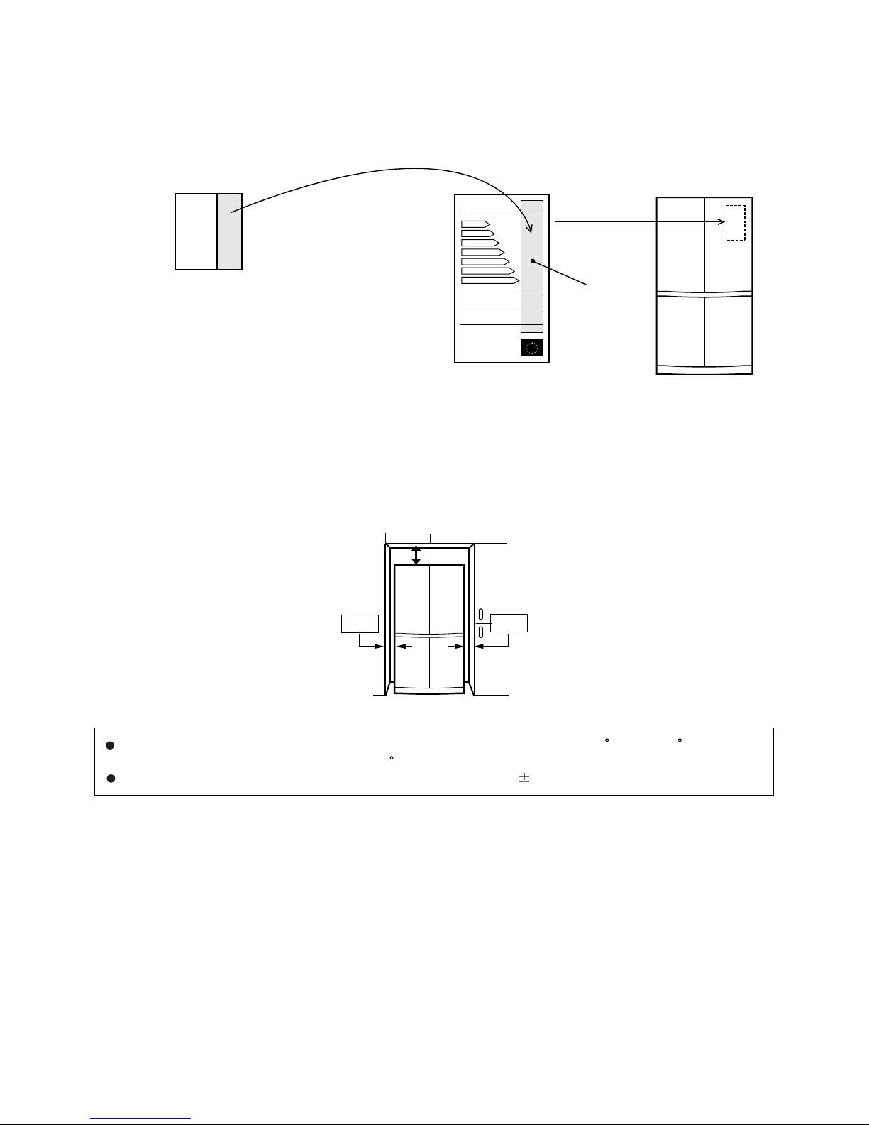
[1] ENERGY LABEL
Usage of "the ENERGY LABEL"
• When displaying this refrigerator in the shop-window, attach the "ENERGY LABEL" to it in the following procedure.
[2] INSTALATION
Free standing type
• To ensure adequate ventilation for this refrigerator, install with 6 cm space at the rear and both sides, with aminimum space of 9 cm above the
refrigerator.
"ENERGY LABEL (DATA)"
(This label is in Operation manual)
"ENERGY LABEL (BASE)"
of each language
Refrigerator
Data part
E
B
A
C
D
E
G
F
G
Fix the data part of
"ENERGY LABEL (DATA)"
on the data part of
"ENERGY LABEL (BASE)"
6cm
6cm
9cm
This refrigerator shall be used under the ordinary place condition between +5 C and +38 C of ambient
temperature, and also not be left under -10 C for long days.
To be used this refrigerator within the range of the rated voltage˴6%
Page 3

SJF800SPSL
2 – 1
SJF800SPSL
ServiceManual
CHAPTER 2. SPECIFICATION
Items SJ-F750SP SJ-F800SP
Type 4 Door
Outer dimensions Height 1720mm(67.7") 1830mm(72.0")
Width 890mm(35.0") 890mm(35.0")
Depth 770mm(30.3") 770mm(30.3")
Rated storage volume Total 556liter(19.6cu.ft) 605liter(21.4cu.ft)
Freezer 211liter(7.5cu.ft) 211liter(7.5cu.ft)
Refrigerator 345liter(12.1cu.ft) 394liter(13.9cu.ft)
Rated gross volume 602liter(21.3cu.ft) 653liter(23.1cu.ft)
Defrosting System Heater system
Start Automatic
Finish Automatic
Temperature control Automatic (Adjustable)
No-frost freezer Yes
Interior lamp (LED) 36
Plasmacluster light (LED, Blue) 1
Caster 4
Evaporating pan 1 (unremovable)
Refrigerator Compartment R-shelf ass'y 2
V-shelf ass'y 1
Bttl rack ass'y 1
Fruit case ass'y 1
Fresh case ass'y 1
V-case ass'y 1
Door pocket ass'y 3
Btl-pok L ass'y 1
Btl-pok R ass'y 1
U-pok door 1
Utility pok ass'y 1
Egg pok ass'y — 1
Egg tray 1
Freezer Compartment Ice cube maker 1
Quick ice maker 1
Ice storage ass'y 2
F-case S ass'y 3
F-case L ass'y 2
Control panel Plasmacluster Yes
Express Ice making Yes
Express Freezing Yes
Vacation mode Yes
Door alarm Yes
Timer Yes
Temp. control Yes
Child lock Yes
Aluminum panel Yes
Deodorizing unit (Honeycomb type) Yes
RATING
Items SJ-F750SP SJ-F800SP
Rated voltage (V~) 220-240
Rated frequency (Hz) 50
Climate class ST
Rated current (A) 0.8-0.9
Rated input of heating systems (W) 173-206
Defrosting input (W) 173-206
Refrigerant (Charging quantity) [Flammable] R-600a(52g) R-600a(52g)
Insulation blowing gas [Flammable] Cyclo pentane (HC)
Net Weight (kg) 111 114
Page 4
SJF800SPSL
2 – 2
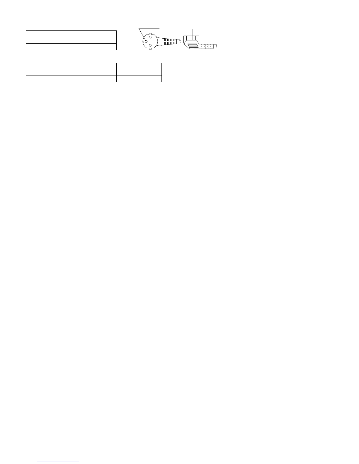
PLUG TYPE
Plug cord 2 pin + Earth
Plug type CS
Destination mark E
COLOR
Items -SL -BK
Outside color Silver Black
Inside color White White
Receptacle
Page 5

SJF800SPSL
3 – 1
SJF800SPSL
ServiceManual
CHAPTER 3. FICHE
1
NO.
2
3
4
5
6
8
9
11
12
13
14
Trade mark
Items
Description
Remarks
Model name
Type
Energy efficiency class
Eco-award mark
Energy consumption
(220V 50Hz at 25 C)
Star rating of frozen food
compartment
Temperature rise time
Freezing capacity
Climate class
Noise
10 No frost
7
Net storage volume of frozen
food storage compartment
SJ-F750SP SJ-F800SP
Category; 7
A+
ST ST
38 dB(A)
re1pw
38 dB(A)
re1pw
450
kWh/year
1017
kWh/year
1066
kWh/year
345 L
No frost
11 h
9.5 kg /24h
Net storage volume of fresh
food storage compartment
Category; 7
A+
465
kWh/year
394 L
11 h
9.5 kg /24h
880/92
EN153
86/594/EEC
No frost
THE FICHE (according to ANNEX : 94/2/EC)
15
Maximum allowable electricity
consumption (Emax)
(96/57/EC)
211 L
4-STAR
211 L
4-STAR
E max
(2.92)(2.79) (kWh/day)
fridge / freezer
A++/A+/A~G
at 25
at 25
Page 6
SJF800SPSL
4 – 1
SJF800SPSL
ServiceManual
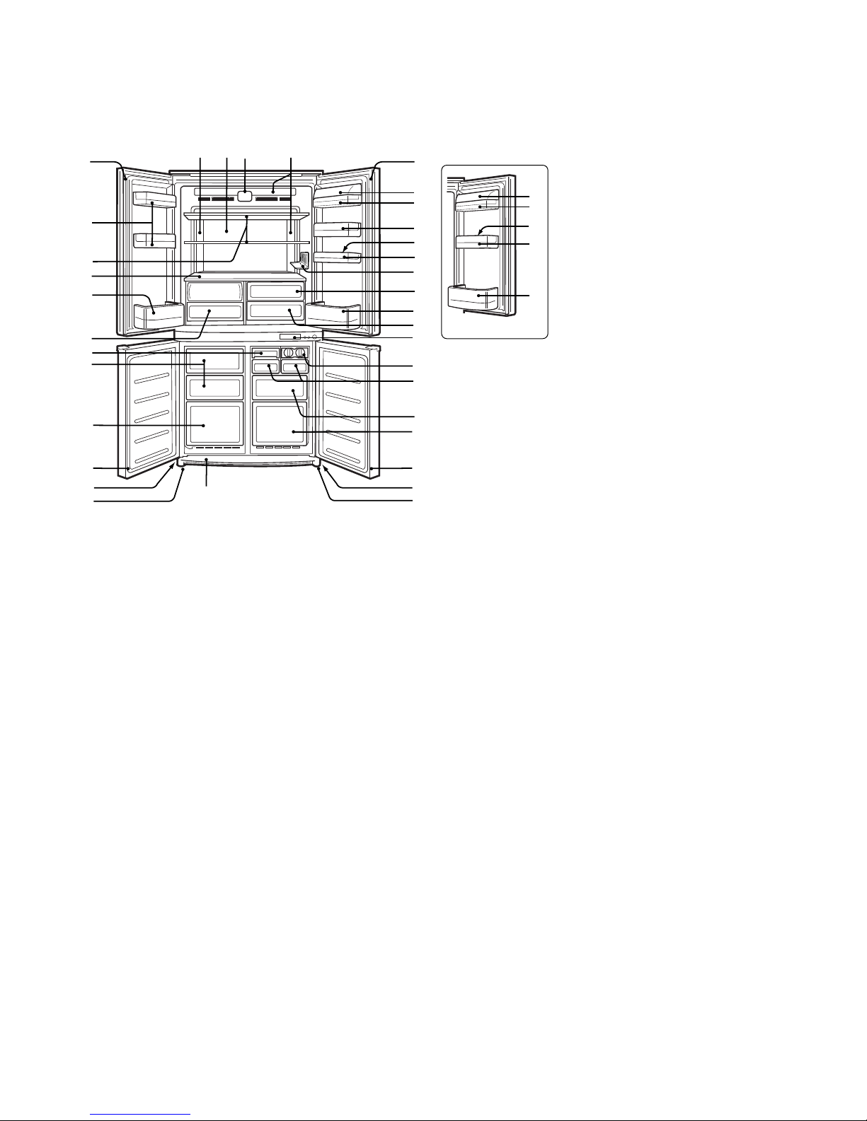
CHAPTER 4. DESIGNATION OFVARIOUS PARTS
[1] EXTERNAL DESCRIPTION
The names in parenthesis “[ ]” are the denominations used in the REPLACEMENT PARTS LIST.
25
13
12 14
13
25
15
1
17
18
19
20
22
21
26
23
24
7
8
25
9
10
1
2
3
4
5
6
7
8
25
9
10
11
16
15
16
1
22
17
SJ-F800SP
SJ-F750SP
1. Door pocket [Door pocket ass'y]
2. Refrigerator shelf [R-shelf ass'y]
3. Shelf [V-shelf ass'y]
4. Bottle pocket(left) [Btl-pok L ass'y]
5. Vegetable crisper [V-case ass'y]
6. Quick ice maker [Quick ice maker]
7. Freezer case(small) [F-case S ass'y]
8. Freezer case(large) [F-case L ass'y]
9. Caster
10. Adjustable feet [Adjustable leg ass'y]
11. Foot cover [Base cover]
12. Aluminum panel [AL panel]
13. Refrigerator LED Light
[LED pwb ass'y]
14. Plasmacluster Light [PCI pwb ass’y]
15. Utility pocket cover [U-pok door]
16. Utility pocket [Utility pok ass'y]
17. Egg holder [Egg tray]
18. Egg pocket [Egg pok ass’y]
(Only for SJ-F800SP)
19. Bottle rack [Bttl rack ass'y]
20. Fruit case [Fruit case ass'y]
21. Fresh case [Fresh case ass'y]
22. Bottle pocket(right) [Btl-pok R ass'y]
23. Ice cube maker [Ice cube maker]
24. Ice cube box [Ice storage ass'y]
25. Magnetic door seal [Door packing]
26. Control panel
Page 7
SJF800SPSL
4 – 2
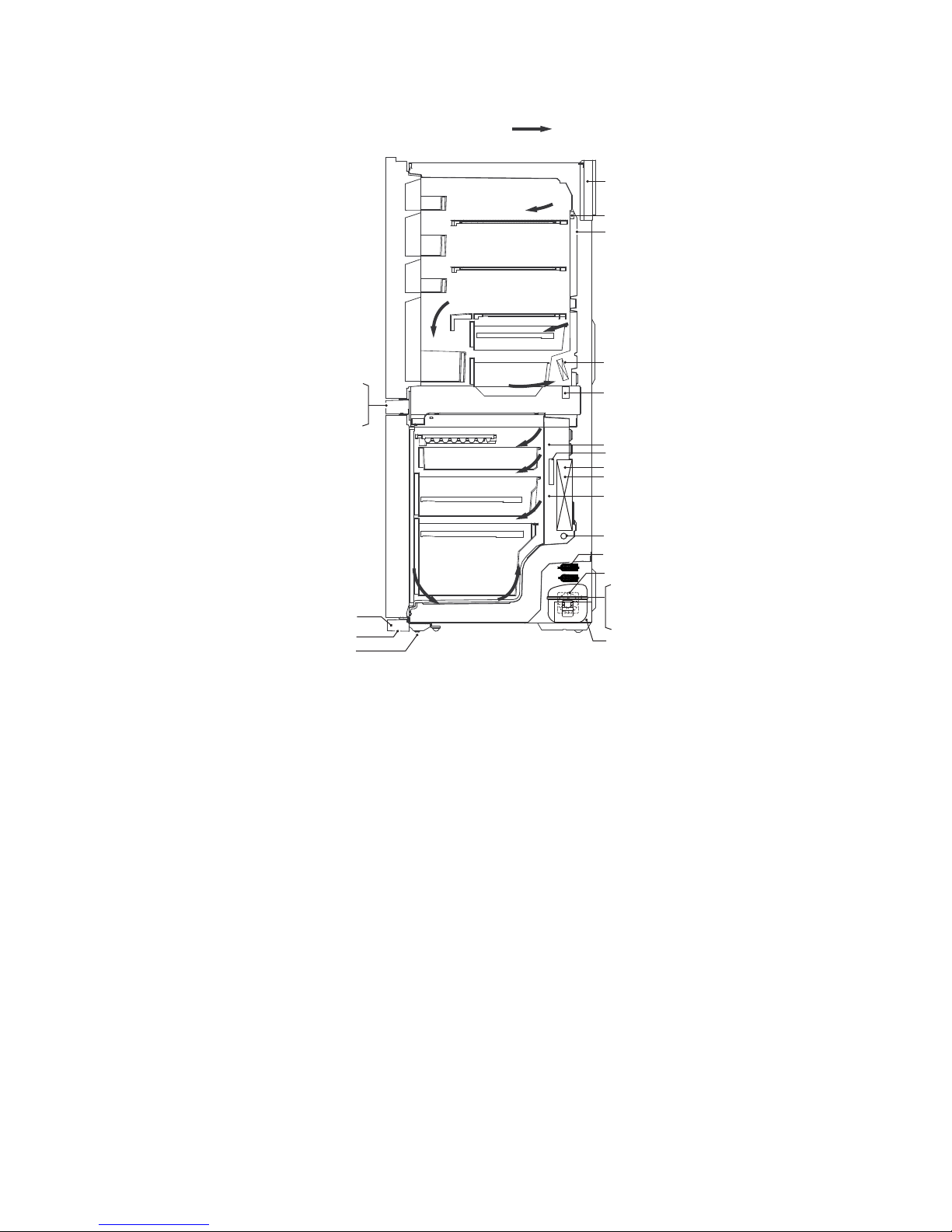
[2] CONSTRUCTIONS
PWB-s ass'y
Ionizer-K
R-thermistor
R fan motor
Damper ass'y
Compressor
Protector
Starting relay
Sub condenser
Evaporator
Fuse ass'y
F-thermistor
Def-thermistor
F-fan motor
Defrost heater
Reed sw
LCD PWB s ass'y
Control panel
C fan motor
Running capacitor
Evaporating pan
Foot cover
Adjustable feet
Caster
mark : cold air flow
Page 8
SJF800SPSL
5 – 1
SJF800SPSL
ServiceManual
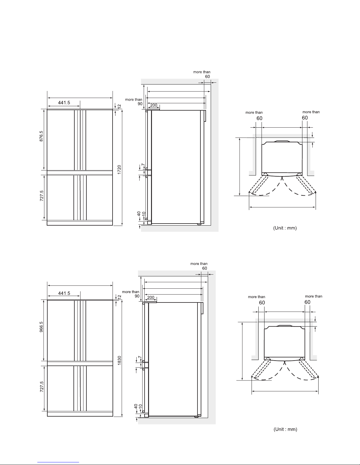
CHAPTER 5. DIMENTIONS
[1] OUTER DIMENTIONS AND CLEARANCE
1. SJ-F750SP
2. SJ-F800SP
890
50
1180
1500
787
890
60
817
770
890
1180
1500
890
60
50
787
770
817
Page 9
SJF800SPSL
5 – 2
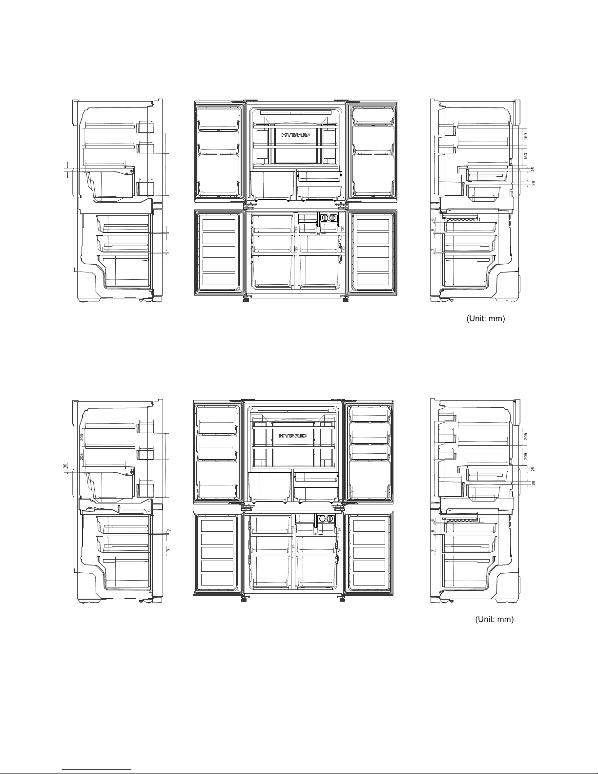
[2] INNER DIMENTIONS
The dimensions between shelves can be changed by setting the shelves on the other rails.
1. SJ-F750SP
2. SJ-F800SP
186340
77
30
328
328
250
136.5
136.5
136.5
346
260.5
365
365
142.5
142.5
316
316
316
316
316
316
708
708
708
282
217
166
217
320
282
96.5
125.5
308
308
298 298
142.5142.5260.5
260.5
125.5 125.5
80
80
308
142.5
136.5
136.5
191
328
328
250
240
96.5
188
125.5
66
311
406
80
365
346
142.5
260.5
168
66
150150
340 230
708
708
328
328
250
136.5
136.5
136.5
217
166
365
365
142.5
142.5
346
260.5
316
316
316
282
217
320
282
96.5
125.5
316
316
316
316
308
308
142.5142.5260.5
298
168
125.5
66
80
80
125.5
308
142.5
260.5
298
136.5
136.5
136.5
191
328
328
250
240
96.5
188
125.5
311
66
406
80
365
346
142.5
260.5
225345
708
190135345
Page 10
SJF800SPSL
6 – 1
SJF800SPSL
ServiceManual
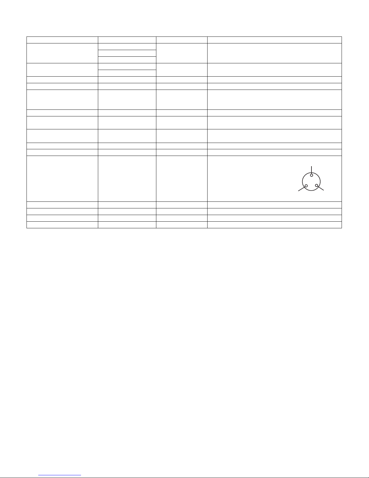
CHAPTER 6. LIST OF ELECTORICAL PARTS
“ • “ denotes parts that cannot be replaced or parts that cannot be replaced as an individual unit.
ITEMS TYPE NAME RATING SPECIFICATIONS
R Thermistor — DC 5V R0 = 6.4 kΩ, B(0) = 3811
F Thermistor — DC 5V R0 = 6.4 kΩ, B(0) = 3811
Defrost Themistor — DC 5V R0 = 15 kΩ, B(0) = 3811
• RD Heater (F750SP) — 220-240V 8021Ω 6.6W at 230V
• RD Heater (F800SP) — 220-240V 8365Ω 6.32W at 230V
Thermo. fuse SF70E 250V 10A Working temp. : 70 °C
Defrost heater MM6-4350 220-240V 286Ω 185W at 230V
R-Fan motor D08A-12PM.05(K) DC12V 0.07A —
F-Fan motor FBA12J15VXD DC14.5V 0.28A —
C-Fan motor D09T-12CS307(EX) DC12V 0.09A —
Damper NSBC101FA1 DC12V —
Reed SW MS-332/651 DC5V Magnetic Switch
SW Magnet FM10.9X7X25.4(SR-3) — Magnet Switch
Lamp (Side) FPWB-A617CBKZ DC14.5V 150mA white LED Lamp
Lamp (Top) FPWB-A619CBKZ DC14.5V 75mA white LED Lamp
LCD operation FPWB-A615CBKZ DC14.5V Blue LCD
Ionizer indicator FPWB-A621CBKZ DC14.5V Blue LED
Compressor EGM90CLC 220-240V/50Hz Cooling capacity : 218W (50Hz)
Main coil : 18.40Ω
Aux. coil : 25.50Ω
(at 25 °C)
Starting Relay PTH8M220MD2 — 22Ω (at 25 °C)
Overload Relay (Protector) 4TM189NFBYY-53 — Open/Close : 120/ 61 °C
Running capacitor RC-EZA254CBZZ — 400V 5μF
Ionizer-K (Plasmacluster unit) CKITTA131AKKZ DC15V 4.55kV p-p (Second wave)
Common
Aux. coil
Main coil
Page 11
SJF800SPSL
7 – 1
SJF800SPSL
ServiceManual
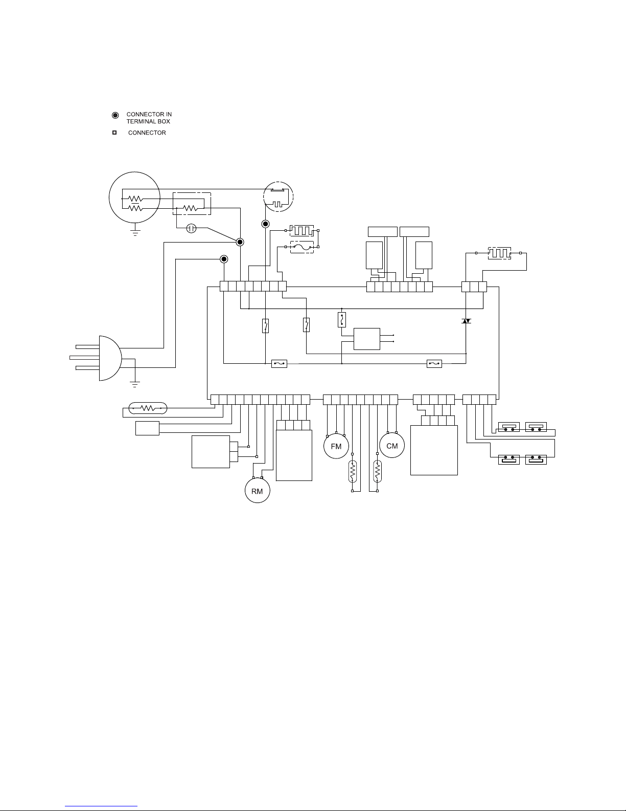
CHAPTER 7. WIRING DIAGRAM
[1] WIRING DIAGRAM
Be sure to replace the electrical parts with specified ones for maintaining the safety and performance of the set.
Fuse1 Fuse3
Fuse2
Relay2
AC/DC
DC
MAIN
PWB
G
B
Br
Relay1
111222333
1234
1234
445
12345
566778
12345678
9
112234
1234
5678
9
101112
8
Compressor
Starting relay
Protector
Fuse
Defrost Heater
Running capacitor
R-door heater
F-reed SW
R-reed SW
Defrost-thermistor
LCD Control
PWB
F-thermistor
Damper
Plasmacluster
R-thermistor
Plasmacluster light
Light
Plug / Cord
LED
LED
LED
LEDLED
Page 12
SJF800SPSL
7 – 2
[2] ELECTRIC ACCESSORIES LAYOUT
Page 13

SJF800SPSL
8 – 1
SJF800SPSL
ServiceManual
CHAPTER 8. FAILURE DIAGNOSIS
[1] OUTLINE OF CONTROL
1. ON/OFF Control of Compressor
• ON/OFF of the compressor will be controlled depend on the temperature detected by
the R-thermistor and F-thermistor. (Normal cooling control)
• In case the surrounding temperature is high at the power supply input, the compressor will be ON at once and the normal cooling control will start
after several hours.
• When the rapid ice making or rapid freezing is requested by user during the operation, the compressor will be ON and cooling operation will be
started regardless of the detected temperature by the thermistors. However, if requested during the defrosting operation, the request will be executed after the completion of defrosting and ON of the compressor might be delayed.
• During 5 minutes after the compressor stops, it will not start regardless of the detected temperature by R-thermistor and F-thermistor.
2. Defrosting
Microcomputer calculates the appropriate timing of defrosting and defrosting is made automatically. Therefore no manual operation by user is
required. The cycle of defrosting varies depend on the usage condition of the refrigerator. (Maximum time about 50 hours, minimum time 8 hours)
3. Thermistor
Thermistors are installed in 4 places; in the refrigerator and freezer compartment, and close to the Control panel and Evaporator. (R-thermistor, Fthermistor, Outside temp-thermistor, Def-thermistor)
R-thermistor and F-thermistor detects the temperature in the refrigerator and freezer compartment respectively and controls ON/OFF of compressor.
Def-thermistor detects the temperature around the evaporator and shows the progress of defrosting.
Outside temp-thermistor detects the surrounding temperature of refrigerator. It decides the defrost timing and changes the operation mode when the
outside temperature is high.
[2] WHEN THE DEFROSTING FAILURE IS DOUBTFUL
Execute the Self-Diagnosis Mode. (Refer to the Chapter “SELF-DIAGNOSIS MODE”)
• In case the diagnosis result is “EE03” (Def-thermistor system defect), follow up the flowchart of EE03. (In case of any abnormity in the Def-thermistor, defrosting will not be made for safety reasons.)
• In case the diagnosis result is “EE07” (Defrost defect), follow up the flowchart of EE07.
(This diagnosis result will be displayed when defrosting is made for 120 minutes, the maximum time length. In this case, the defect of PWB itself
and also the breakage of heater and heater circuit (melt down of current fuse and temperature fuse) are considerable.)
[3] RE-SETTING OF MICROCOMPUTER AT POWER FAILURE
• At the power failure for over 0.4 second, the control of the microcomputer will might be reset.
• Microcomputer might continue to operate for approximately 10 seconds maximum at power failure depending on the load at the operation. Approximately 30 seconds is necessary for the definite power OFF condition.
• When the power is re-supplied, the normal cooling will be resumed.(If cold enough in the cabinet, the microcomputer will begin defrosting in 40
minutes according to the condition.)
• The temperature and operation mode set by user will be maintained even if a power failure occurred.
(However defrosting, rapid freezing, rapid ice making, and timer will not be maintained.)
• When the self diagnosis is made, each mode and setting are resumed to the initial condition.
Page 14
SJF800SPSL
8 – 2
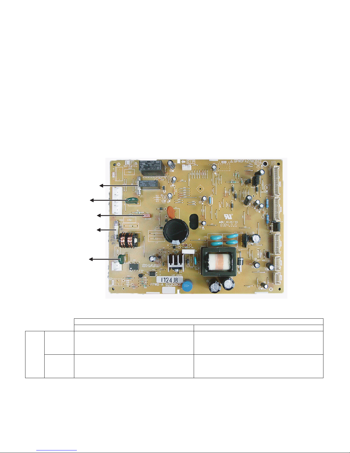
[4] DIAGNOSIS METHOD OF FAILURE AROUND PWB
First of all, check by using the self-diagnosis.
In case that the power supply doesn't enter, check by the following procedure.
1. Disconnect power supply and check the following point.
• Is there any failure portion in inserting connectors?
2. Detach the PWB and check the appearance.
• Is there any burning or abnormal damage?
3. Check the conditions of the fuse and the varistor. (Fuse and varistor are located at the position in the figure.)
• Under the condition of power supply plug connected;
In case of no cooling and no indoor lamp lighting, there might be a possibility of fuse (F1 or F2) melt down.
When the fuse F1 or F2 is melt down, PWB does not operate at all.
When the fuse F3 is melt down, defrosting heater and refrigerator door heater are not electrified. (Defrosting error will be diagnosed as
“Defrosting failure” by the self diagnosis.) In this case, the cooling performance may deteriorate or dew generation may occur on the door,
because the defrosting is not done.
• Melting in the fuse cannot be checked visually (as the safer one than transparent glass tube is used). Be sure to detach the connector “CN1”
before measuring the resistance between the both ends of the fuse by the tester.
• Next, measure the resistance value between the both leads of the varistor.
4. Check whether the temperature (resistance value) shown by R-thermistor is correct or not. (Refer to the table below.)
• Detach the connector “CN4” on the PWB and measure the resistance between 1 and 2 pins of harness side.
5. Check whether the temperature (resistance value) shown by Def-thermistor is correct or not. (Refer to the table below.)
• Detach the connector “CN5” on the PWB and measure the resistance value between 6 and 7 pins of harness side.
6. Check whether the temperature (resistance value) shown by F-thermistor is correct or not. (Refer to the table below.)
• Detach the connector “CN5” on the PWB and measure the resistance value between 4 and 5 pins of harness side.
Var is tor
Normal (over approx.1.5MΩ) Damage
Fuse
Melting
Flow of excessive current is considerable for some reasons.
Check for any portion to cause short circuits especially on
the primary circuit.
There is a possibility of excessive voltage applied from outside with the factor such as thunder etc. When repeated with a
factor other than thunder, there might be the apparatus near
by generating noises.
Conduction
Fuse and varistor are normal.
Possibility to be caused by excessive current or voltage
near the power supply is low. Proceed to the other check
item.
-
Var istor 1
Fuse 2
Fuse 1
Var istor 3
Fuse 3
Page 15
SJF800SPSL
8 – 3
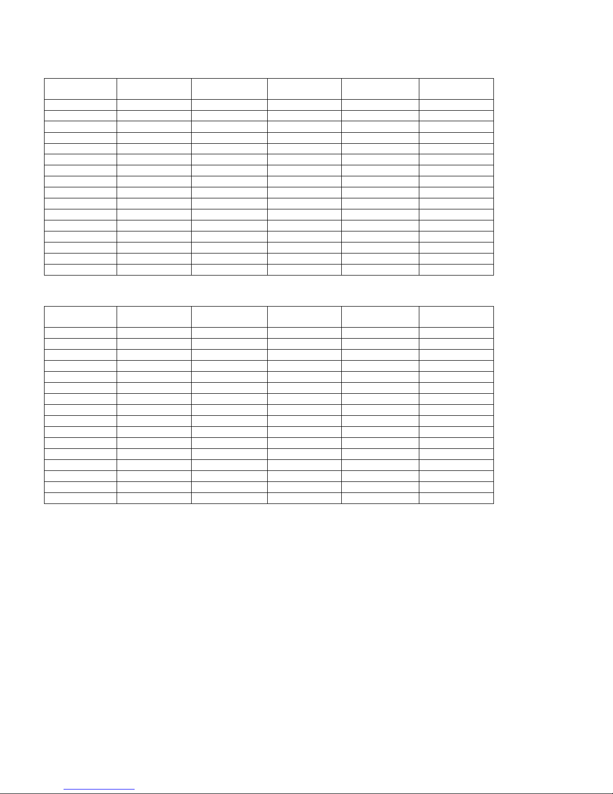
[5] CONVERSION TABLE BETWEEN TEMPERATURE AND RESISTANCE VALUE
1. R-thermistor
2. Def-thermistor, F-thermistor
Temperature
(°C)
Resistance Value
(KΩ)
Temperature
(°C)
Resistance Value
(KΩ)
Temperature
(°C)
Resistance Value
(KΩ)
-25 26.1 -9 10.3 7 4.52
-24 24.54 -8 9.75 8 4.3
-23 23.08 -7 9.24 9 4.1
-22 21.72 -6 8.76 10 3.91
-21 20.46 -5 8.3 11 3.73
-20 19.27 -4 7.87 12 3.56
-19 18.16 -3 7.47 13 3.4
-18 17.13 -2 7.09 14 3.24
-17 16.16 -1 6.74 15 3.1
-16 15.25 0 6.4 20 2.47
-15 14.4 1 6.08 25 1.99
-14 13.6 2 5.78 30 1.61
-13 12.85 3 5.5 35 1.31
-12 12.15 4 5.23 40 1.08
-11 11.49 5 4.98
-10 10.88 6 4.74
Temperature
(°C)
Resistance Value
(KΩ)
Temperature
(°C)
Resistance Value
(KΩ)
Temperature
(°C)
Resistance Value
(KΩ)
-25 61.17 -9 24.13 7 10.58
-24 57.51 -8 22.85 8 10.09
-23 54.1 -7 21.65 9 9.61
-22 50.92 -6 20.52 10 9.16
-21 47.94 -5 19.46 11 8.74
-20 45.17 -4 18.46 12 8.34
-19 42.57 -3 17.51 13 7.96
-18 40.14 -2 16.63 14 7.6
-17 37.86 -1 15.79 15 7.26
-16 35.74 0 15 20 5.79
-15 33.74 1 14.26 25 4.66
-14 31.87 2 13.55 30 3.77
-13 30.12 3 12.89 35 3.08
-12 28.48 4 12.26 40 2.52
-11 26.94 5 11.67
-10 25.49 6 11.11
Page 16
SJF800SPSL
8 – 4
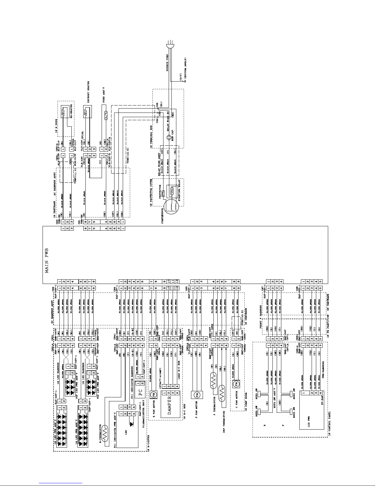
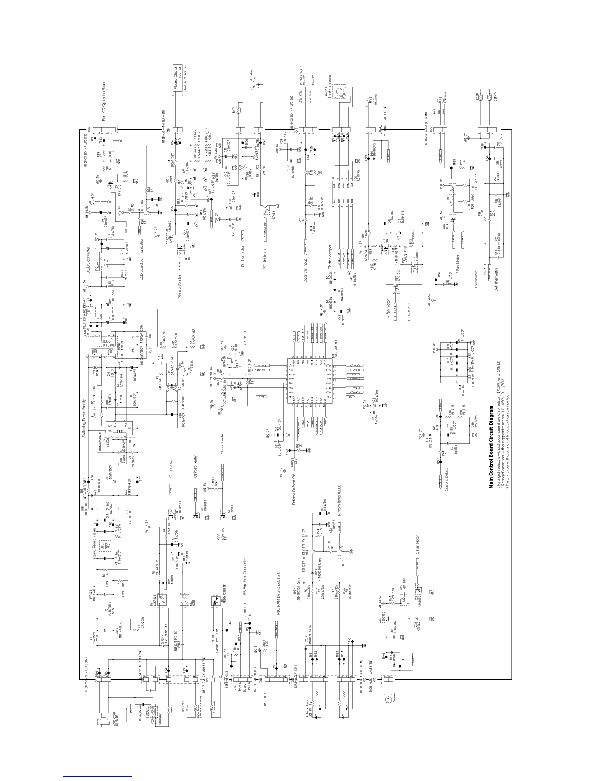
[6] CIRCUIT DIAGRAM OF MAIN PWB
Page 17
SJF800SPSL
8 – 5
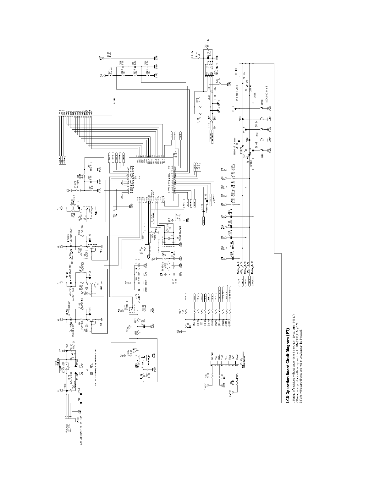
[7] CIRCUIT DIAGRAM OF LCD PWB
Page 18
SJF800SPSL
9 – 1
SJF800SPSL
ServiceManual
CHAPTER 9. SELF-DIAGNOSIS MODE
1. Entering method of the mode
1) Press the [Select] button on the LCD panel over 5 seconds at the opening condition of the
freezer and refrigerating room doors.
2) With a beep sound of buzzer, the self-diagnosis mode is entered. When the self-diagnosis
mode is not entered by the above operation, defect of Reed SW system can be considered.
2. When the self-diagnosis mode is entered, the following movements will be made. Forced release operation is not prepared for the self-diagnosis
mode. It returns to the normal movement after a lapse of 2 minutes.
• During the express ice making, express freezing or timer, the mode is released.
• Plasmacluster will not release the mode, and ON is forced for 2 minutes whether it is ON or OFF.
• When the self-diagnosis mode is entered, beep sound for reminding of closing the door must not be sounded for 20 minutes.
• Defect and various conditions are shown by the beeping buzzer pattern.
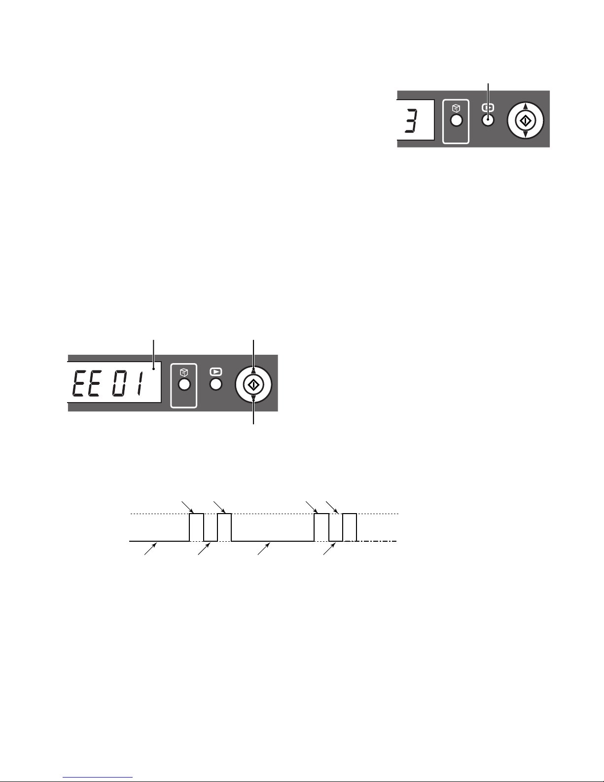
• Defect and various conditions are displayed on the LCD panel. In case of plural defects and various conditions, these are displayed one after
another by button operation and all contents are notified.
3. Display of self-diagnosis
• Display example of LCD panel (at the defect of F-thermistor system)
• Buzzer notice example; (at defrost defect, 2 times of 0.5 second ON)
ḥ
EXPRESS
ICE
SELECT BUTTON
SELECT
EXPRESS
ICE
Results of diagnosis
Move to the next display.
Move to the previous display.
SELECT
ON
OFF
3 seconds stop
Repeating
0.5 second stop
3 seconds stop
0.5 second stop
0.5 second 0.5 second 0.5 second 0.5 second
Buzzer
Page 19
SJF800SPSL
9 – 2
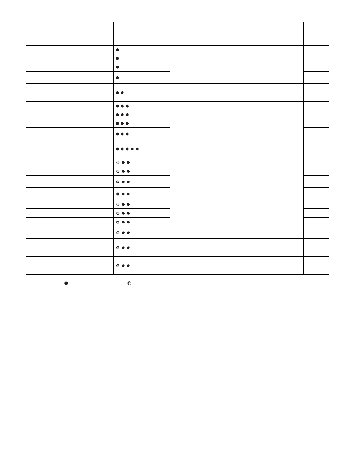
• Buzzer: =0.5 sec ON/0.5 sec OFF, =2 sec ON/0.5 sec OFF
No
.
Status Buzzer LCD
Display
Content
Correspon-
dence
method
- No defects None - - - -
1 F-thermistor system defect EE 01
Defect of each thermistor, short circuit/wire breakage of thermistor wiring and defect of main PWB
→[1]
2 R-thermistor system defect EE 02 →[2]
3 DEF-thermistor system defect EE 03 →[3]
4
Outside temperature-thermistor
system defect
EE 04 →[4]
5 Defrost defect EE 07
Wire breakage of fuse•defrost heater, defect of main PWB
(120-minute defrosting has been occurred continuously 2 times
within the past 48 hours.)
→[5]
6 F fan motor system defect EE 08
Defect of each fan motor, fan-lock and defect of wiring/main
PWB
(When fan motor is ON, over current or no current is detected.)
→[6]
7 C fan motor system defect EE 09 →[7]
8 R fan motor system defect EE 10 →[8]
9
Ionizer (Plasmacluster) system
defect
EE 11 →[9]
10 LCD Display communication defect EE 12
Short circuit/wire breakage of wiring and defect of LCD or main
PWB (Communication with LCD PWB has been abnormal over
3 times within the past 48 hours.)
→[10]
11 F-thermistor system defect history EH 61
Defect of thermistor system has been occurred over 1 minute
continuously within the past 48 hours.
→[1]
12 R-thermistor system defect history EH 62 →[2]
13
DEF-thermistor system defect history
EH 63 →[3]
14
Outside temperature-thermistor
system defect history
EH 64 →[4]
15 F fan motor system defect history EH 66
Defect of fan motor has been occurred over 3 times continuously within the past 48 hours.
→[6]
16 C fan motor system defect history EH 67 →[7]
17 R fan motor system defect history EH 68 →[8]
18
Ionizer (Plasmacluster) electrifying
defect history
EH 72
Defect of Ionizer (Plasmacluster) electrifying has been
occurred over 3 times continuously within the past 48 hours.
→[9]
19 F-room high temperature history EH 76
Temperature of F-thermistor has been reached over -10°C continuously for 6 hours or more within the past 48 hours. (except
right after the installation)
→[1]
20 R-room high temperature history EH 77
Temperature of R-thermistor has been reached over +10°
C
continuously for 6 hours or more within the past 48 hours.
(except right after the installation)
→[2]
Page 20
SJF800SPSL
9 – 3
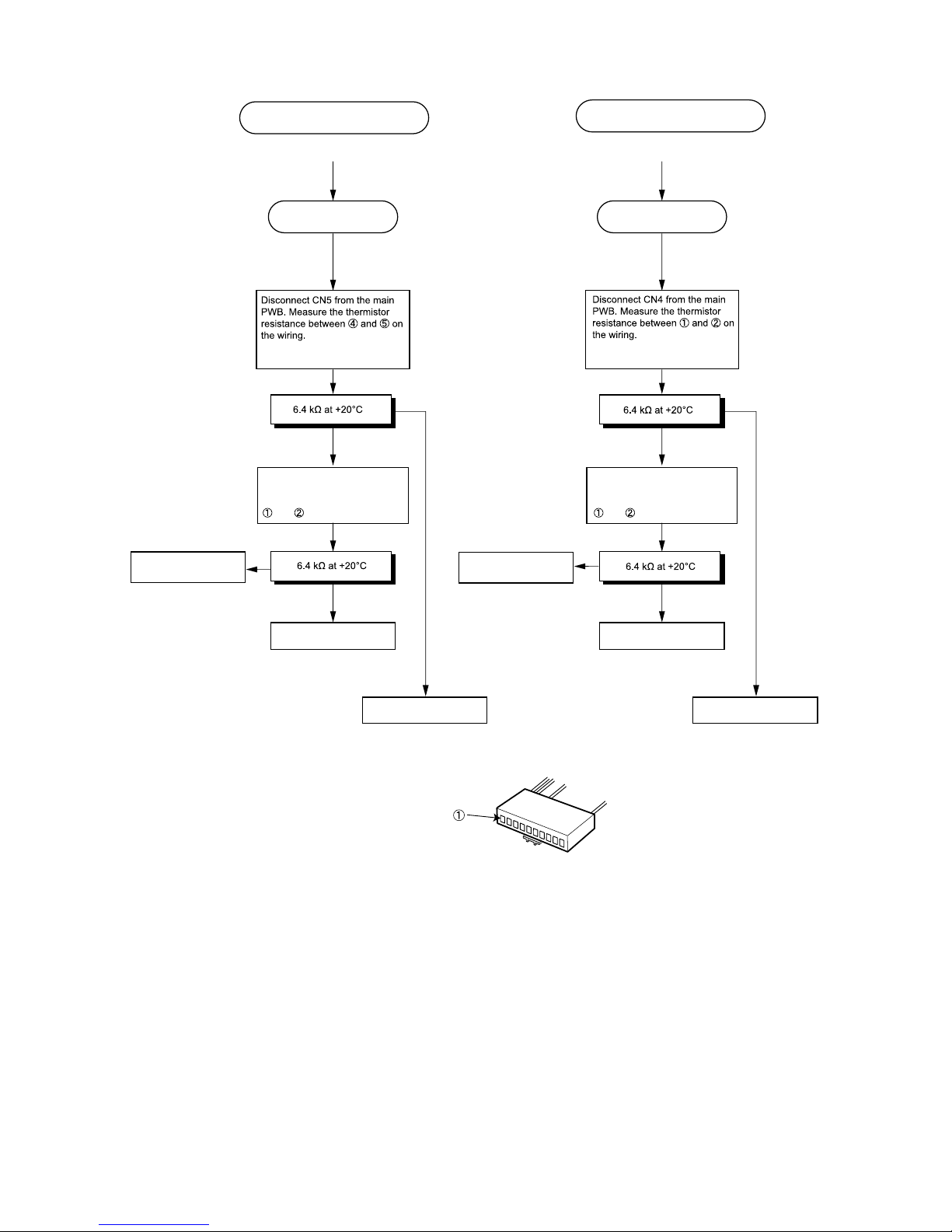
Correspondence method
Power OFF Power OFF
Replace F-thermistor.
Replace main PWB.
(F-thermistor system diagnosis) (R-thermistor system diagnosis)
OK
NG
and .
Replace R-thermistor.
Replace main PWB.
Remove 6P connector from R
louver Assy and measure the
thermistor resistance between
and .
EE 01 / EH 61 / EH 76
EE 02 / EH 62 / EH 77
[1]
[2]
Remove 4P connector (flat) from
E.V. cover Assy and measure the
thermistor resistance between
NG
OK
NG
NG
OK
OK
Check the F-thermistor
system wiring
Check the R-thermistor
system wiring
Page 21

SJF800SPSL
9 – 4
(DEF-thermistor system diagnosis)
Turn power OFF. Reopen door and re-energize.
(Buzzer beeps continuously)
Power OFF
Replace DEF-thermistor.
Replace main PWB.
OK
NG
NG
and .
EE 03 / EH 63
EE 04 / EH 64
(Ambient air temperature - thermistor system diagnosis)
Replace LCD-PWB.
Ambient air
temperature thermistor
is installed on
LCD-PWB.
(Defrosting diagnosis)
EE 07
OK?
Replace main PWB.
Replace fuse Assy.
Replace
defrost heater.
NO
YES
NO
YES
YES
NO
YES
NO
Forced defrosting (Measurement is impossible when
DEF-thermistor is set at 10°C or higher because
defrosting ends immediately)
After approx. 15 sec., the voltage
measured across
and of CN1
on the main PWB is equal to supplied
voltage? (e.g. 240 V)
Disconnect CN1 from the main PWB. Measure the
resistance between
and of CN1 on the wiring.
Resistance of 3P connector on E.V.
cover K is normal?
Check defrost heater wiring for loose
connection or disconnection.
Check cause of defrosting failure
· Check door packing
· Check mounting seal of E.V. cover Assy
2P connector on E.V. cover
Assy is carrying current?
[3]
[4]
[5]
Remove 4P connector (flat) from
E.V. cover Assy and measure the
thermistor resistance between
OK
Check the Def-thermistor
system wiring
See CHAPTER 4. (Heater resistance)
Page 22

SJF800SPSL
9 – 5
Turn OFF and ON power.
Fan locked?
Check position of fan.
Replace F fan motor.
Replace main PWB.
YES
YES
NO
NO
NO
YES
Measure voltage between and
of CN5 on the main PWB.
CN5
- : Approx. 14 V
- : Approx. 2~4 V
EE 08 / EH 66
(F fan motor system diagnosis)
EE 09 / EH 67
(C fan motor system diagnosis)
EE 10 / EH 68
(R fan motor system diagnosis)
F fan motor
rotates?
Check cause of defrosting
failure
· Dislocation of fan
· Check door packing
· Installation of E.V. cover Assy
· Defective seal
(If OK)
Replace C fan motor.
Adjust and power ON again.
Fan locked?
NO
YES
NO
YES
Measure voltage between and
of CN5 on the main PWB:
Approx. 9 to 13 VDC?
Loose connection or disconnection of
C fan motor system (motor connector
voltage)
Replace main PWB or C fan motor.
(If OK)
Replace R fan motor.
Adjust and power ON again.
Fan locked?
NO
YES
NO
YES
Measure voltage between and
of CN4 on the main PWB:
Approx. 9 to 13 VDC?
Loose connection or disconnection of
R fan motor system (motor connector
voltage)
Replace main PWB or R fan motor.
[6][
7
]
[8]
7
8
Page 23

SJF800SPSL
9 – 6
Replace Plasmacluster. Replace LCD-PWB Assy.
(Ionizer system diagnosis)
EE 11 EE 12
(LCD system diagnosis)
Insert connector.
NO
NO
YES
and of CN4 on the main PWB
are positively engaged?
YES
and of 6P connector on R
louver Assy are positively engaged?
Insert connector.
NO
NO
YES
CN6 on the main PWB is positively
engaged?
YES
5P connector on control panel is
positively engaged?
[9]
[10]
5
6
Page 24

SJF800SPSL
10 – 1
SJF800SPSL
ServiceManual
CHAPTER 10. MODE FOR DISPLAY
1. Entering method of the mode
Within 2 minutes after main power input, press the [ ] button over 3 seconds at the opening condition of the refrigerating room door.
NOTE: This cannot be made at the ON condition of CHILD LOCK.
2. Release of the mode
Press the [ ] button over 3 seconds at the opening condition of the refrigerating room door.
(Even without the above operation, release can be made by main power OFF.)
3. Movement in the mode
1) Compressor, each fan motor, heater and Plasmacluster are stopped.
2) Damper is always made [OPEN] condition.
3) Indoor lamp is lit when refrigerating room door is open.
4) LCD display
• Icon will be lit at random.
• In case of starting the timer, express ice making or express freezing, forced termination is made in 20 seconds.
ḥ
EXPRESS
ICE
BUTTON
SELECT
Page 25

SJF800SPSL
11 – 1
SJF800SPSL
ServiceManual
CHAPTER 11. DISASSEMBLING/ASSEMBLING PROCEDURES
CAUTION: DISCONNECT THE UNIT FROM THE POWER SUPPLY BEFORE ANY REPAIRING.
[1] REFRIGERATOR COMPARTMENT
1. Disassembling procedures
1. Remove the accessories(shelves, fresh case, etc.).
2. Remove the v shelf ass'y.
3. Remove the r-case stay
4. Remove the r con cover s, and disconnect the connector.
5. Remove the r lamp cover and the r-louver ass'y.
6. Remove the r control box ass'y.
Parents parts name Included electrical parts
R-louver ass'y
Plasmacluster unit, Lr led pwb ass'y, Top led pwb ass'y, Pci pwb ass'y,
Lr led harness, Pci indicator harness, R-thermistor
R control box ass'y Damper ass'y, Lead r-c box, R fan motor
Latch
V shelf ass'y
Latch
R-case stay
Latch
R-louver ass'y
R con cover s
Latch
Screw
Screw
Screw
R lamp cover r
R lamp cover l
Screw
Latch
Latch
R contorol box ass'y
Page 26

SJF800SPSL
11 – 2
2. Assembling procedures of R CONTROL BOX ASS’Y.
1. Insert Lead r-c box to Damper ass’y and next stick A-sealer rc-d to Damper ass’y (lead wire shall be fix by A-sealer rc-d)
2. Stick A-sealer rc-a to R fan motor.
3. Stick A-sealer ag4 to deodorizer.
A-sealer rc-c
A-sealer ag4
Deodorizer
R-C box cover
A-sealer rc-d
A-sealer rc-a
R fan motor
R air guider a
R air guider b
Damper ass'y
Lead r-c box
A-sealer rc-g
A-sealer rc-f
Damper ass’y
Lead r-c box
Damper ass’y
A-sealer rc-d
10~20 over rap
R fan motor
A-sealer rc-a
A-sealer ag4
A-sealer ag4
Deodorizer
Page 27

SJF800SPSL
11 – 3
4. Insert R fan motor and damper ass’y to R air guider b, and Stick A-sealer rc-f to R air guider b.
5. Assemble R air guider b to R air guider a. Wire-harness are fixed with kraft tapes. Stick A-sealer rc-c to R air guider a/b (lead wire shall surely
insert slot of R air guider).
6. Stick A-sealer rc-g to R air guider a.
7. Insert Deodorizer to R-C box cover. Assemble these sets and R-C box cover.
Damper ass’y
R air guider b
R fan motor
View from A
>PS<
A-sealer rc-f
R air guider b
View from A
R fan motor
R air guider b
Lead rc box
Kraft tape
20*30
R air guider a
A-sealer rc-c
A-sealer rc-c
Kraft tape
20*30
Kraft tape
20*30
Kraft tape
20*30
Slot
View from b
Kraft tape
Section A-A
Wire
Kraft tape
20*30
View from b
R fan motor
R air guider b
(Unit : mm)
HOLE
All around
0~2
A-sealer rc-g
>PS<
[Front side]
R-C box cover
Deodorizer
Page 28

SJF800SPSL
11 – 4
3. Assembling procedures of R-louver ass’y.
1. Connect Pci indicator harness to
Pci pwb ass'y.
2. Insert Pci pwb ass'y into Led holder.
3. Fix Light guide on Led holder.
4. Stick Al sheet l-guide to Light guide
and Led holder.
5. Stick A-sealer r-lv a to R-louver
insu.
A- sealer r-lv a
Plasmacluster
unit
R-louver insu
Pci indicator harness
Lr led harness
Lr led harness
R lamp cover t
Top led pwb ass’y
Lr led pwb ass’y
Al panel
R-louver
LIght guide
Led holder
Pci pwb ass’y
Lr led pwb ass’y
Al sheet l-guide
R thermistor
A-sealer r-lv b
Light guide
Pci pwb ass’y
Pci indicator harness
Pass the harness
through the hole.
Led holder
Al sheet l-guide
Light guide
Al sheet l-guide
40x90mm
Led holder
0~2
Standard for affixing of
Al sheet l-guide
Put the tape which
protruded in the side
A-sealer r-lv a
A-sealer r-lv a
R-louver insu
>PS<
B886
extention
Stick A-sealer r-lv a to
the bottom side.
(Both right and left side)
Page 29

SJF800SPSL
11 – 5
6. Fix Al panel to R-louver.
7. Fix 4) ass'y on the R-louver with tapping screw.
8. Connect Lr led harness to Lr led pwb ass'y and Top led pwb ass'y.
9. Fix 8) ass'y on R-louver.
10.Connect Pci indicator harness to plasmacluster unit.
11.Insert Plasmacluster unit into 5) ass'y.
12.Fix 5) ass'y to R-louver.
13.Fix R lamp cover t by taping screw to R-louver.
14.Fix Plasmacluter unit and Pci indicator harness by buffalo tape to R-louver insu.
15.Stick A-sealer r-lv b to R-louver insu.
?P
?Q
?R?S
R-louver
Al panel
Al panel
Al panel
Al panel
Bend hook
of Al panel
Bend hook
of Al panel
Bend hook
of Al panel
Lr led harness
Pci indicator harness
Lr led harness
Lr led pwb ass’y
T
op led pwb ass’y
Hook
T
apping screw
R lamp cover t
Lr led pwb ass’y
Plasmacluter
unit
5) ass'y
4) ass'y
A-sealer r-lv b
Pci indicator harness
R-louver insu
Buffalo tape
30x40
Buffalo tape
30x40
over lap
All around
3
A-sealer r-lv b
Page 30

SJF800SPSL
11 – 6
16.Fix each harness by buffalo tape to R-louver.
Lr led harness
R-thermistor
Pass the harness
through the hole.
Pass the harness
through the hole.
Tapping
screw
R-louver
Hook Hook
Hook
Lr led pwb ass’y
Hook
Hook
Pci indicator harness
Lr led harness
Fix R-thermistor with hooks.
Hook
Buffalo tape
30 x 40
Tapping
screw
Buffalo tape
30x40
Buffalo tape
30x50
Buffalo tape
30 x 50
Buffalo tape
30 x 50
Page 31

SJF800SPSL
11 – 7
[2] FREEZER COMPARTMENT
1. Disassembling procedures
1. Remove the accessories(shelves, case, etc.).
2. Remove the i-case stay.
3. Remove the c-part ffb ass'y.
4. Remove the f return cover.
5. Remove the fan louver.
6. Remove the connect cover, and disconnect the connector.
7. Remove the ev cover ass'y.
Parents parts name Included electrical parts
Ev cover ass'y F/df-thermistor, F fan motor
Evaporator ass'y Fuse ass'y
Def-heater ass'y Defrost heater
Latch
I-case stay
Screw
C-part ffb ass'y
Latch
Latch
Latch
Latch
F return cover
Screw
Fan louver
Screw
Latch
Screw
Screw
Ev cover ass'y
Connect cover
Page 32

SJF800SPSL
11 – 8
2. Assembling procedures of C PARTITION FFB ASS’Y.
1. Stick Sealer c to V-Partition lfb.
2. Fix V-partition lfb and V-Partition rfb with the tapping screw.
Sealer d
Sealer c
Sealer e
V-partition rfb
V-partition lfb
V-PARTITION LFB
SEALER C
V-PARTITION LFB
V-PARTITION RFB
TAPPING SCREW
Page 33

SJF800SPSL
11 – 9
3. Stick Sealer d to the back side.
Stick Sealer e to the bottom side.
3. Assembling procedures of E.V. COVER ASS’Y.
SEALER D
SEALER E
F/df-thermistor
Sealer fm
EV-cover insu
EV-cover sealer
EV cover
EV-c sealer l
EV-cov. sealer b
EV-cov. sealer c
F fan motor
Fan louver
E.V. PE-AL sheet
Connect cover
Page 34

SJF800SPSL
11 – 1 0
1. Assembly F fan motor
i) Sticking of sealer to F fan motor.
ii) Insert F fan motor to E.V cover .Then fix with tapping screw.
2. Sticking of sealers and PE-AL sheet to E.V cover.
3. Insert F/df-thermistor ( wire color : Blue) to E.V cover.
4. Insert E.V cover insulation to E.V cover.
5. Insert F/df-themistor ( wire color : White) to connect cover.
6. Fix 5) ass’y to E.v cover with tapping screw.
Tappig screw
(Unit : mm)
F/df- thermistor
Page 35

SJF800SPSL
11 – 11
4. Banding the connectors
1. It is necessary to bind the connector joint of the Defrost heater and fuse ass’y in the band.
Only the lower side
3P-connector
(Defrost heater)
2P-connector
(Fuse ass'y)
lock
lock
Attach to each inside face. (reverce of lock)
Page 36

SJF800SPSL
11 – 1 2
[3] HOW TO REMOVE THE CONTROL BASE
1. Insert the sharp tool into gap between control panel and control base, and then push it for take out the claw from control base.
2. Remove the control panel carefully by hand.
(Take out the claw of control panel from control base)
3. Insert the screw driver for take out 5 screws in the position as see the picture.
4. Take off the connector (2 connectors) and then remove the control base.
INSERT SHARP IN THIS POSITION
CLAW
Control panel
REMOVE IT BY THIS WAY
CLAW
screw
screw
Control base
screw screw
screw
Reed sw (for refrigerator compartment)
(harness color : Red)
( 4mm)
( 4mm)
( 4mm)( 5mm)
( 5mm)
Reed sw
(for freezer compartment)
(harness color : Black)
Control base
Connector
Page 37

SJF800SPSL
11 – 1 3
[4] DEFROST HEATER
1. Taking-out Evaporator
1. Take-out C Partition ffb ass’y.
2. Take-out Fan louver.
3. Take-out E.V cover ass’y.
4. As shown in the above figure, pull the upper part of Evaporator
toward you, pull it diagonally so that the pipe of Evaporator does
not contact the convex part of food liner.
5. Pull the Evaporator for remove as shown in the above figure.
NOTE: When pulling Evaporator and bending the pipes,pay attention
so as not to break and deform the pipes. Still, take care not to
hurt yourself by fin of Evaporator.
2. Replacement of Def. heater.
1. Remove the center screw of Heater support to take it off from the
food liner.
2. Raise the protrusion part of Heater support. Then remove Heater
cover.
3. Open Def.heater fixed part of Heater support to the right and left,
then remove Def.heater.
E vaporator
F ood liner co nve x pa rt
Food liner convex part
Evaporator
Pipe
Evaporator
Heater support
Heater cover
Protrusion parts
Protrusion part of Drain support al(2 pcs.)
Heater cover
Def. heater ass'y
Heater support
Fixed parts
Def.heater
Heater support
Page 38

SJF800SPSL
11 – 1 4
4. Replace Def. heater with new one.
5. Bend end of heater support.
6. Assemble Defrost heater to Heater Support.
7. Assemble Heater cover to Heater Support. Bend top edge to outside.
8. Roll the leading wire Sealer to Lead wire Defrost Heater.
3. Installing of Evaporator
1. Install Evaporator as shown in 1-3 in the reverse order of 1-4.
2. Correct the deformed fin.
NOTE: 1.When installing Evaporator, take care not to deform signifi-
cantly and break the pipes.
2.Take care not to damage the lead wires and hurt yourself by
the fin of Evaporator.
Heater support
(Unit : mm)
Page 39

SJF800SPSL
11 – 1 5
[5] WHEN LEFT AND RIGHT DOORS ARE NOT ON THE SAME LEVEL
1. Cause
The floor is not flat and refrigerator is slanting.
2. Adjustment
1. Unscrew 4 screws on the bottom of the cabinet,and remove the foot cover.
2. Adjust the adjustable feet as follows:
[When left door is raised]
1) Raise and then lower the both feet until they touch the floor.
2) Measure the height difference between right and left doors.
3) Extend the right adjustable foot until the left adjustable foot floats by the distance equal to the door level difference.
4) Several days are required until the both feet touch the floor and refrigerator seats stably.
5) If the height difference is not completely compensated, place a plate of the right thickness under the adjustable foot.
NOTE: When the right door is higher than the left door, extend the left adjustable foot.
Foot cover
Adjustable foot
3) Lower the foot
at right side.
1) Touch floor surface.
2) Check height difference.
3) Raise by the height difference
between doors.
Left door
is raised
Page 40

SJF800SPSL
12 – 1
SJF800SPSL
ServiceManual
CHAPTER 12. COOLING UNIT
[1] COOLING UNIT
Page 41

SJF800SPSL
12 – 2
[2] LOCATION
1. Location 1
2. Location 2
Capillary tube
Eva. pan
pipe ass’y
-HC-L
-HC-S
DC
P-Connector
From Bottom condenser
to Hot pipe
From Compressor
to CHRG-PIPR-HC-
From CHRG-PIPE-HC-S
to Dryer
From Suction pipe ass
to S Connector
From S connector
to Compressor
From Compressor
to DC P-Connector
From DC P-Connector
to Sub condernser
From Sub condenser
to E pan pipe s ass
From E pan pipe s ass
to BTM condenser
From Hot pipe
to Dryer
Form Dryer
to Capillary tube
Page 42

SJF800SPSL
12 – 3
Page 43

PartsGuide
SJF800SPSL
PARTS GUIDE
Refrigerator-freezer
MODELS
SJ-F750SP-SL/BK
SJ-F800SP-SL/BK
[1] SJ-F750SP DOOR
[2] SJ-F750SP CABINET1
[3] SJ-F750SP CABINET2
[4] SJ-F750SP CYCLE
[5] SJ-F750SP OTHERS
[]
CONTENTS
[6] SJ-F800SP DOOR
[7] SJ-F800SP CABINET1
[8] SJ-F800SP CABINET2
[9] SJ-F800SP CYCLE
[10] SJ-F800SP OTHERS
INDEX
This document has been published to be used
for after sales service only.
The contents are subject to change without notice.
Page 44

SJF800SPSL
3-40
3-21
3-11
5-21
5-22
5-23
5-27
5-28
5-27
5-27
5-28
5-22-1
5-24
3-2
5-1
3-22
5-6
5-5
5-4
5-3
5-2
5-2
3-32
3-1-3
3-1-2
3-1
3-21-3
3-21-2
3-21-5
3-21-1
3-31-1
3-31-4
3-31-2
3-31-5
3-31-3
3-21-4
3-1-3
3-1-1
3-11-2
3-1-1
3-31
5-3-1
3-28
3-28
3-2
3-8
3-19
3-9
3-19
3-8
3-9
3-55
3-51
3-57
3-53
3-26
3-54
3-58
3-52
3-56
3-55
3-51
3-57
3-53
3-6
3-54
3-58
3-52
3-56
3-55
3-51
3-57
3-53
3-26
3-54
3-58
3-52
3-56
3-55
3-51
3-57
3-53
3-6
3-54
3-58
3-52
3-56
3-46
3-47
3-47
3-46
3-47
[1] SJ-F750SP DOOR
2
Page 45

NO. PARTS CODE
PRICE
RANK
NEW
MARK
PART
RANK
DESCRIPTION
[1] SJ-F750SP DOOR
3-1 FDORFC066CBKZ BR F-door l ass'y [SL]
3-1 FDORFC073CBKZ BT F-door l ass'y [BK]
3-1-1 LSTPMA008CBM0 AD F-door stopper r
3-1-2 LSTPPA146CBFA AF Fd-stp spring l
3-1-3 NBRGPA022CBFA AC Nylon bearing 3s
3-2 FPACGA431CBYA AT F door packing
3-6 JHNDPA296CBPZ AY Fd-handle
3-8 PPACGA226CBZA AM F-sub packing a
3-9 PPACGA227CBZA AK F-sub packing b
3-11 FDORFC067CBKZ BR F-door r ass'y [SL]
3-11 FDORFC074CBKZ BT F-door r ass'y [BK]
3-11-2 LSTPPA147CBFA AF Fd-stp spring r
3-19 PPACGA241CBZA AK F-sub packing c
3-21 FDORRC074CBKZ BT R-door l ass'y [SL]
3-21 FDORRC094CBKZ BT R-door l ass'y [BK]
3-21-1 LSTPPA150CBFA AF Stp-spring tl
3-21-2 LSTPPA151CBFA AF Stp-spring bl
3-21-3 LSTPPA152CBFA AF R lock spring l
3-21-4 MSLI-A070CBFA AE Door cam tl
3-21-5 MSLI-A071CBFA AE Door cam bl
3-22 FPACGA504CBYA AX R door packin l
3-26 JHNDPA298CBPZ AZ Rd-handle
3-28 PPACGA294CBZA AP R-sub packing
3-31 FDORRC075CBKZ BT R-door r ass'y [SL]
3-31 FDORRC095CBKZ BT R-door r ass'y [BK]
3-31-1 LSTPPA148CBFA AF Stp-spring tr
3-31-2 LSTPPA149CBFA AF Stp-spring br
3-31-3 LSTPPA153CBFA AF R lock spring r
3-31-4 MSLI-A068CBFA AE Door cam tr
3-31-5 MSLI-A069CBFA AE Door cam br
3-32 FPACGA505CBYA AX R door packin r
3-40 HBDGDB020CBZA AZ Badge
3-46 PSEL-E036CBZZ AE R-sub packing sealer
3-47 PSEL-E040CBZZ AE
3-51 HDECQA597CBFA AF Hd base t
3-52 HDECQA598CBFA AF Hd base b
3-53 HDECQA599CBTA AG Hd-cover t [SL]
3-53 HDECQA599CBTB AG Hd-cover t [BK]
3-54 HDECQA600CBTA AG Hd-cover b [SL]
3-54 HDECQA600CBTB AG Hd-cover b [BK]
3-55 HDECQA601CBTA AG Hd cap t [SL]
3-55 HDECQA601CBTB AG Hd cap t [BK]
3-56 HDECQA602CBTA AG Hd cap b [SL]
3-56 HDECQA602CBTB AG Hd cap b [BK]
3-57 LPLTPA559CBPZ AE Hd-support t
3-58 LPLTPA560CBPZ AE Hd-support b
5-1 FPOK-A270CBKZ AW Btl-pok l ass'y
5-2 FPOK-A271CBKZ AP Door pocket ass'y
5-3 FPOK-A272CBKZ AZ Btl-pok r ass'y
5-3-1 LSTYPA044CBFA AL B-pok partition
5-4 FPOK-A273CBKZ AN Utility pok ass'y
5-5 GDORPA078CBFA AN U-pok door
5-6 UTNA-A397CBFA AH Egg tray
5-21 FSRA-A244CBYZ AP Ice cube maker
5-22 FSRA-A245CBKZ BM Quick ice maker
5-22-1 PSKR-A329CBFA AK Q-ice parition
5-23 FYOK-A232CBKZ AV Ice storage assy
5-24 LSTYPA043CBFA AW I-case stay
5-27 FYOK-A306CBKZ AZ F-case s ass'y
5-28 FYOK-A305CBKZ BB F-case l ass'y
Rd packing sealer
SJF800SPSL
3
Page 46

SJF800SPSL
2-5
2-7-2
2-121
2-122
2-7-1
2-7
2-8-2
2-7-1
5-12-3
5-12-1
5-12-2
5-11
5-12
5-13
5-13-1
5-13-2
5-13-3
2-8
5-11-3
5-11-1
5-11-2
2-115
5-16
5-18
5-17
5-15
2-116
2-117
2-118
2-108
2-107
2-113
2-114
2-106
2-105
2-111
2-112
2-3
2-4
5-14
5-42
4-21
2-145
2-146
2-144
2-142
2-143
2-93
2-93
2-36
2-49
5-25
5-11-4
3-45
5-11-5
5-12-4
90-33
2-119
[2] SJ-F750SP CABINET1
4
Page 47

NO. PARTS CODE
PRICE
RANK
NEW
MARK
PART
RANK
DESCRIPTION
[2] SJ-F750SP CABINET1
2-3 PCOVPA398CBFA AR Hinge cover [SL]
2-3 PCOVPA398CBFF AT Hinge cover [BK]
2-4 LPLTPA416CBTA AX Hinge support-t [SL]
2-4 LPLTPA416CBTB AW Hinge support-t [BK]
2-5 JHNDMA025CBPZ AE Carrying bar
2-7 FLEGPA127CBKZ AN Leg holder-ls k
2-7-1 FAJS-A028CBKZ AZ Adjustable leg ass'y
2-7-2 FLEGPA123CBYZ AH Leg holder-lk
2-8 FLEGPA128CBKZ AN Leg holder-rs k
2-8-2 FLEGPA124CBYZ AH Leg holder-rk
2-36 PCAP-A006CBFW AB Screw cover
2-49 LSTPPA108CBFA AC Chilled stopper
2-93 PCAP-A068CBFA AC C sliding cap a
2-105 DHNG-A537CBMZ BA F-hinge lt assy
2-106 DHNG-A538CBMZ BA F-hinge rt assy
2-107 DHNG-A539CBMZ BA F-hinge lb assy
2-108 DHNG-A540CBMZ BA F-hinge rb assy
2-111 FHNG-A231CBMZ AH R-hinge lbk
2-112 MSLI-A072CBFA AE Hinge cam bl
2-113 FHNG-A232CBMZ AH R-hinge rbk
2-114 MSLI-A073CBFA AE Hinge cam br
2-115 FHNG-A233CBYZ AH R-hinge ltk
2-116 MSLI-A074CBFA AE Hinge cam tl
2-117 FHNG-A234CBYZ AH R-hinge rtk
2-118 MSLI-A075CBFA AE Hinge cam tr
2-119 FPLTPA152CBKZ AN Temp.meter ass'y
2-121 GCOV-A280CBFA AV F-ret cover bl
2-122 GCOV-A281CBFA AV F-ret cover br
2-142 PSEL-C558CBZZ AD Sealer c
2-143 PSEL-C559CBZZ AD Sealer d
2-144 PSEL-C560CBZZ AD Sealer e
2-145 PSKR-A327CBFA AU V-partition lfb
2-146 PSKR-A328CBFA AU V-partition rfb
3-45 PPACGA244CBZA AF
4-21 LX-TZA091CBTA AE Special screw [SL]
4-21 LX-TZA091CBTF AD Special screw [BK]
5-11 FTNA-A537CBKZ BE R-shelf ass'y
5-11-1 UTNA-A396CBRA AY R-glass shelf
5-11-2 UWAKPA046CBFA AQ G guard rb
5-11-3 UWAKPA044CBFA AV G guard r
5-11-4 LPLTMA753CBPZ AP R shelf support
5-11-5 HDEC-A085CBZZ AR G guard r trim
5-12 FTNA-A536CBKZ BE V-shelf ass'y
5-12-1 UTNA-A395CBRA AY V-glass shelf
5-12-2 UWAKPA045CBFA AQ G guard vb
5-12-3 UWAKPA043CBFA AV G guard v
5-12-4 HDEC-A084CBZZ AR G guard v trim
5-13 FTNA-A419CBKZ AR Bttl rack ass'y
5-13-1 LHLD-A712CBFA AK B-r holder
5-13-2 NSFT-A041CBFA AE B-r shaft
5-13-3 UTNA-A398CBFA AK Bottle rack
5-14 FYOK-A303CBKZ AZ Fruit case assy
5-15 FYOK-A304CBKZ AY Fresh case assy
5-16 FYOK-A229CBKZ AZ V-case ass'y
5-17 GFTA-A117CBRA AR V-case door
5-18 LSTYPA042CBFA AT R-case stay
5-25 LRAL-A092CBFA AM Ice room rail
5-42 HGRL-A243CBFA AS Base cover [SL]
5-42 HGRL-A243CBFF AS Base cover [BK]
90-33 TLAB-B220CBRZ AE Temp.caution label
F-sub packing d
SJF800SPSL
5
Page 48

SJF800SPSL
2-66
6-12
2-95
2-20
2-67
1-21
2-2
1-55
2-132
2-147
2-133
2-131
1-10
2-1
1-6
2-138
2-139
2-34
1-27
2-74
2-38
2-72
2-39
2-27
1-4
1-26
2-97
2-16
2-21
2-28
2-22
2-140
2-100
1-17
2-120
2-141
6-31
2-149
2-148
1-1
2-125
2-25
2-26
2-55
2-161
2-29
1-64
1-65
1-62
1-64
1-61
1-61
2-163
1-63
2-162
2-56
1-45
2-58
2-165
2-164
2-160
1-3
2-37
2-37
2-166
2-167
[3] SJ-F750SP CABINET2
6
Page 49

NO. PARTS CODE
PRICE
RANK
NEW
MARK
PART
RANK
DESCRIPTION
[3] SJ-F750SP CABINET2
1-1 RH-HXA108CBZZ AW F/df-thermistor
1-3 RH-HXA123CBZZ AM R-thermistor
1-4 DTHM-A031CBKZ AX Damper ass'y
1-6 RMOTRA096CBZZ BE F fan motor
1-10 FSW-LA001CBKZ AW Reed sw ass'y
1-17 FFS-TA087CBKZ AM Fuse ass'y
1-21 FHETBA193CBZZ BA Defrost heater
1-26 QCNW-B146CBZZ AK Lead r-c box
1-27 RMOTRA095CBZZ BA R fan motor
1-45 CKITTA131AKKZ BE Plasmacluster unit
1-55 FPWB-A615CBKZ BL Lcd pwb s ass'y
1-61 FPWB-A617CBKZ BF Lr led pwb ass'y
1-62 FPWB-A619CBKZ BE Top led pwb ass'y
1-63 FPWB-A621CBKZ BB Pci pwb ass'y
1-64 QCNW-B363CBZZ AH Lr led harness
1-65 QCNW-B364CBZZ AM Pci indicator harness
2-1 HPNL-A466CBFA AX Control panel [SL]
2-1 HPNL-A468CBRA AV Control panel [BK]
2-2 GDAI-A078CBTA AU Control base
2-16 GCOV-A282CBFB AX Ev-cover
2-20 PSEL-C573CBZZ AE E.v.pe-al sheet
2-21 PFPFPB565CBFZ AE Ev-cover insu
2-22 PSEL-C569CBZZ AC Ev-cover sealer
2-25 PCOV-A435CBFA AK R lamp cover l
2-26 PCOV-A436CBFA AK R lamp cover r
2-27 GCOVPA274CBFA AX R-c box cover
2-28 HGRL-A244CBFA AX Fan louver
2-29 PCOV-A434CBFA AK R lamp cover t
2-34 PFIL-A047CBEZ AC Deodorizer
2-37 LHLD-A860CBFA AE Screw cover
2-38 PGID-A169CBFZ AG R air guider a
2-39 PGID-A170CBFZ AE R air guider b
2-55 MLOV-A079CBFA AY R-louver
2-56 PFPFPB887CBFZ AK
2-58 PSEL-E015CBZZ AG A-sealer r-lv a
2-66 PSHEMA296CBPZ AC Heater cover
2-67 LPLTPA428CBPZ AQ Heater support
2-72 PSEL-C562CBZZ AC A-sealer rc-a
2-74 PSEL-C564CBZZ AG A-sealer rc-c
2-95 LANG-A064CBPZ AF Eva holder 75
2-97 PCOV-A340CBFA AF R con cover s
2-100 GCOVPA199CBFZ AF Connect cover
2-120 GCOV-A279CBFA AM F return cover
2-125 LPLTMA933CBPZ BP Al panel
2-131 JBTN-A030CBMA AH Button
2-132 JBTN-A031CBMA AK Button l
2-133 JBTN-A032CBMA AH Button j
2-138 PSEL-C600CBZZ AD Ev-cov.sealer b
2-139 PSEL-C601CBZZ AE Ev-cov.sealer c
2-140 PSEL-C640CBZZ AD Ev-c sealer l
2-141 PSEL-C661CBZZ AD Sealer fm
2-147 LHLD-A713CBFA AE Lcd-pwb holder
2-148 PSEL-C669CBZZ AD A-sealer rc-d
2-149 PSEL-C081CBEZ AA A-sealer ag4
2-160 GCOV-A344CBFA AH R-cbox return cover
2-161 HDECAA097CBRA AP Plasma badge
2-162 LHLD-A861CBFA AH Led holder
2-163 LPLTPA561CBFA AH Light guide
2-164 PSEL-E068CBZZ AE A-sealer rc-f
2-165 PSEL-E069CBZZ AD A-sealer rc-g
2-166 PSEL-E076CBZZ AE Al sheet l-guide
2-167 PSEL-E084CBZZ AE A-sealer r-lv b
6-12 PEVA-A201CBZZ BE Evaporator
6-31 PKYU-A035CBE0 AG Sp-butyl h
R-louver insu
SJF800SPSL
7
Page 50

SJF800SPSL
NO. PARTS CODE
PRICE
RANK
NEW
MARK
PART
RANK
DESCRIPTION
2-123
1-50
2-51
1-31
1-23
1-11
6-10
2-24
2-152
2-153
6-11
6-1
4-1
2-87
2-87
6-9
6-2
4-17
1-2
6-4
1-9
6-18
6-5
6-17
6-3
6-7
6-8
2-126
4-10
4-4
2-78
2-99
1-22
4-15
2-77
5-41
1-41
2-80
6-32
2-151
2-136
6-27
6-28
6-27
6-28
2-88
4-14
6-42
6-41
6-36
6-21
6-40
[4] SJ-F750SP CYCLE
[4] SJ-F750SP CYCLE
1-2 RSTT-A179CBZZ AR Ptc relay
1-9 QACC-A156CBZZ AQ Source cord
1-11 RHOG-A189CBEZ AZ Protector
1-22 FCNW-A860CBZZ AH Relay wire assy
1-23 QCNW-A916CBZZ AE Reray wire sc
1-31 RC-EZA254CBZZ AS Running capacitor
1-41 RMOTRA097CBZZ BA C fan motor
1-50 FPWB-A661CBKZ BP Pwb-s ass'y
2-24 GCOVPA200CBFB AR Terminal cover [SL]
2-24 GCOVPA200CBFC AR Terminal cover [BK]
2-51 LHLD-A711CBFA AQ Pwb holder
8
Page 51

SJF800SPSL
NO. PARTS CODE
PRICE
RANK
NEW
MARK
PART
RANK
[4] SJ-F750SP CYCLE
2-77 LHLD-A359CBFA AE T-box holder
2-78 LPLTMA399CBP0 AD Dryer support
2-80 PBOX-A148CBFA AE Terminal box
2-87 LBND-A018CBE0 AP Fastening band a
2-88 LBND-A019CBE0 AB Nylon band
2-99 PPIPPA126CBFZ AF Drain pipe s
2-123 GCOV-A283CBPZ AH Comp.cover
2-126 LHLD-A710CBFZ AH Cfm frame
2-136 LPLTMA553CBP0 AM Ev.pan support
2-151 PSEL-C555CBZZ AD U-sealer rd
2-152 PSEL-C571CBZZ AC Sealer
2-153 PSEL-C662CBZZ AD Sealer fm-b
4-1 LBND-A023CBE0 AC L-band c
4-4 QTAN-A012CBE0 AH Solderless term. B
4-10 QTAN-A013CBE0 AH Solderless term. A
4-14 LBND-A040CBZZ AD Band l150
4-15 LX-BZA090CBZZ AC Special screw
4-17 LX-WZA035CBZZ AB Washer
5-41 USRA-A297CBFA AP Drain pan
6-1 PCMPLA262CBZZ CA Compressor
6-2 PKYU-A173CBKZ AS Rubber mount ass'y
6-3 FCONSA101CBZZ BB Sub condenser
6-4 FFRM-A145CBKZ AM Base frame assy
6-5 FDRY-A006CBK0 AX Dryer ass'y
6-7 LPLTPA418CBFA AF S-con support l
6-8 LPLTPA419CBFA AF S-con support r
6-9 PSPAFA055CBEZ AP Sleeve
6-10 PPIPCA533CBZZ AW Dcp connector
6-11 PPIPCA534CBZZ AW Sp-connector
6-17 PPIPCA517CBZZ AE Chrg pipe hc s
6-18 PPIPCA518CBZZ AE Chrg pipe hc l
6-21 PCOVPA271CBEZ AH Terminal cover
6-27 PGUM-A004CBF0 AH Absorbent rubber a
6-28 PKYU-A175CBZZ AF
6-32 PGUM-A027CBFZ AF Comp. Spacer-e
6-36 FPIPCA255CBKZ AR Eva pan pipe s ass'y
6-40 LHLD-A465CBE0 AG Cord clip
6-41 PKYU-A177CBZZ AF Sub-con holder iir
6-42 PKYU-A178CBZZ AG Comp.cover iir
Sub-con p iir a
[5] SJ-F750SP OTHERS
90-1 TINS-A946CBRZ AM Op-manual
90-3 SPAKCA475CBZZ BC Packing case 73
90-6 CPADBA076CBKZ AU Bottom pad ass'y
90-7 CPADBA077CBKZ AU Top pad ass'y
90-8 TINSEA046CBRZ AG Set label
90-12 TLAB-B822CBRZ AK Energy label
90-13 TLAB-A637CBR0 AG Energy label(gb)
90-13 TLAB-A638CBR0 AG Energy label(d)
90-13 TLAB-A639CBR0 AG Energy label(f)
90-13 TLAB-A640CBR0 AG Energy label(e)
90-13 TLAB-A641CBR0 AG Energy label(i)
90-13 TLAB-A642CBR0 AG Energy label(gr)
90-13 TLAB-A643CBR0 AG Energy label(p)
90-13 TLAB-A644CBR0 AG Energy label(nl)
90-19 TINS-A743CBRZ AE Caution sheet
90-21 TLAB-B396CBRZ AG Caution label rof-hc
90-25 TLAB-B419CBRZ AE Freezer label
90-34 SPADBA260CBZZ AY Top sheet
90-35 SPADBA261CBFZ AK Corner post bl
90-36 SPADBA262CBFZ AK Cornet post br
90-37 SPADBA263CBFZ AM Corner post fl
90-38 SPADBA264CBFZ AM Corner post fr
90-39 SPADBA265CBZZ AT Cab-prot sheet
90-40 SPADBA266CBZZ AM Door prot sheet
90-41 SPADSA032CBZZ AE Door support
90-42 SPADSA033CBZZ AE Door support s
90-43 SSAKHA011CBZZ AP Poly cover
DESCRIPTION
9
Page 52

SJF800SPSL
3-40
3-21
3-11
5-21
5-22
5-23
5-27
5-28
5-27
5-27
5-28
5-22-1
5-24
5-7
3-2
5-1
3-22
5-6
5-5
5-4
5-3
5-2
5-2
3-32
3-1-3
3-1-2
3-1
3-21-3
3-21-2
3-21-5
3-21-1
3-31-1
3-31-4
3-31-2
3-31-5
3-31-3
3-21-4
3-1-3
3-1-1
3-11-2
3-1-1
3-31
5-3-1
3-28
3-28
3-2
3-8
3-19
3-9
3-19
3-8
3-9
3-55
3-51
3-57
3-53
3-26
3-54
3-58
3-52
3-56
3-55
3-51
3-57
3-53
3-6
3-54
3-58
3-52
3-56
3-55
3-51
3-57
3-53
3-26
3-54
3-58
3-52
3-56
3-55
3-51
3-57
3-53
3-6
3-54
3-58
3-52
3-56
3-46
3-47
3-47
3-46
3-47
[6] SJ-F800SP DOOR
10
Page 53

NO. PARTS CODE
PRICE
RANK
NEW
MARK
PART
RANK
DESCRIPTION
[6] SJ-F800SP DOOR
3-1 FDORFC066CBKZ BR F-door l ass'y [SL]
3-1 FDORFC073CBKZ BT F-door l ass'y [BK]
3-1-1 LSTPMA008CBM0 AD F-door stopper r
3-1-2 LSTPPA146CBFA AF Fd-stp spring l
3-1-3 NBRGPA022CBFA AC Nylon bearing 3s
3-2 FPACGA431CBYA AT F door packing
3-6 JHNDPA296CBPZ AY Fd-handle
3-8 PPACGA226CBZA AM F-sub packing a
3-9 PPACGA227CBZA AK F-sub packing b
3-11 FDORFC067CBKZ BR F-door r ass'y [SL]
3-11 FDORFC074CBKZ BT F-door r ass'y [BK]
3-11-2 LSTPPA147CBFA AF Fd-stp spring r
3-19 PPACGA241CBZA AK F-sub packing c
3-21 FDORRC072CBKZ BT R-door l ass'y [SL]
3-21 FDORRC091CBKZ BT R-door l ass'y [BK]
3-21-1 LSTPPA150CBFA AF Stp-spring tl
3-21-2 LSTPPA151CBFA AF Stp-spring bl
3-21-3 LSTPPA152CBFA AF R lock spring l
3-21-4 MSLI-A070CBFA AE Door cam tl
3-21-5 MSLI-A071CBFA AE Door cam bl
3-22 FPACGA502CBYA AX R door packin l
3-26 JHNDPA297CBPZ AZ Rd-handle
3-28 PPACGA293CBZA AP R-sub packing
3-31 FDORRC073CBKZ BT R-door r ass'y [SL]
3-31 FDORRC092CBKZ BT R-door r ass'y [BK]
3-31-1 LSTPPA148CBFA AF Stp-spring tr
3-31-2 LSTPPA149CBFA AF Stp-spring br
3-31-3 LSTPPA153CBFA AF R lock spring r
3-31-4 MSLI-A068CBFA AE Door cam tr
3-31-5 MSLI-A069CBFA AE Door cam br
3-32 FPACGA503CBYA AX R door packin r
3-40 HBDGDB020CBZA AZ Badge
3-46 PSEL-E035CBZZ AE R-sub packing sealer
3-47 PSEL-E040CBZZ AE
3-51 HDECQA597CBFA AF Hd base t
3-52 HDECQA598CBFA AF Hd base b
3-53 HDECQA599CBTA AG Hd-cover t [SL]
3-53 HDECQA599CBTB AG Hd-cover t [BK]
3-54 HDECQA600CBTA AG Hd-cover b [SL]
3-54 HDECQA600CBTB AG Hd-cover b [BK]
3-55 HDECQA601CBTA AG Hd cap t [SL]
3-55 HDECQA601CBTB AG Hd cap t [BK]
3-56 HDECQA602CBTA AG Hd cap b [SL]
3-56 HDECQA602CBTB AG Hd cap b [BK]
3-57 LPLTPA559CBPZ AE Hd-support t
3-58 LPLTPA560CBPZ AE Hd-support b
5-1 FPOK-A270CBKZ AW Btl-pok l ass'y
5-2 FPOK-A271CBKZ AP Door pocket ass'y
5-3 FPOK-A272CBKZ AZ Btl-pok r ass'y
5-3-1 LSTYPA044CBFA AL B-pok partition
5-4 FPOK-A273CBKZ AN Utility pok ass'y
5-5 GDORPA078CBFA AN U-pok door
5-6 UTNA-A397CBFA AH Egg tray
5-7 FPOK-A274CBKZ AN Egg pok ass'y
5-21 FSRA-A244CBYZ AP Ice cube maker
5-22 FSRA-A245CBKZ BM Quick ice maker
5-22-1 PSKR-A329CBFA AK Q-ice parition
5-23 FYOK-A232CBKZ AV Ice storage assy
5-24 LSTYPA043CBFA AW I-case stay
5-27 FYOK-A306CBKZ AZ F-case s ass'y
5-28 FYOK-A305CBKZ BB F-case l ass'y
Rd packing sealer
SJF800SPSL
11
Page 54

SJF800SPSL
2-5
2-7-2
2-121
2-122
2-7-1
2-7
2-8-2
2-7-1
5-12-3
5-12-1
5-12-2
5-11
5-12
5-13
5-13-1
5-13-2
5-13-3
2-8
5-11-3
5-11-1
5-11-2
2-115
5-16
5-18
5-17
5-15
2-116
2-117
2-118
2-108
2-107
2-113
2-114
2-106
2-105
2-111
2-112
2-3
2-4
5-14
5-42
4-21
2-145
2-146
2-144
2-142
2-143
2-93
2-93
2-36
2-49
5-25
5-11-4
3-45
5-11-5
5-12-4
90-33
2-119
[7] SJ-F800SP CABINET1
12
Page 55

NO. PARTS CODE
PRICE
RANK
NEW
MARK
PART
RANK
DESCRIPTION
[7] SJ-F800SP CABINET1
2-3 PCOVPA398CBFA AR Hinge cover [SL]
2-3 PCOVPA398CBFF AT Hinge cover [BK]
2-4 LPLTPA416CBTA AX Hinge support-t [SL]
2-4 LPLTPA416CBTB AW Hinge support-t [BK]
2-5 JHNDMA025CBPZ AE Carrying bar
2-7 FLEGPA127CBKZ AN Leg holder-ls k
2-7-1 FAJS-A028CBKZ AZ Adjustable leg ass'y
2-7-2 FLEGPA123CBYZ AH Leg holder-lk
2-8 FLEGPA128CBKZ AN Leg holder-rs k
2-8-2 FLEGPA124CBYZ AH Leg holder-rk
2-36 PCAP-A006CBFW AB Screw cover
2-49 LSTPPA108CBFA AC Chilled stopper
2-93 PCAP-A068CBFA AC C sliding cap a
2-105 DHNG-A537CBMZ BA F-hinge lt assy
2-106 DHNG-A538CBMZ BA F-hinge rt assy
2-107 DHNG-A539CBMZ BA F-hinge lb assy
2-108 DHNG-A540CBMZ BA F-hinge rb assy
2-111 FHNG-A231CBMZ AH R-hinge lbk
2-112 MSLI-A072CBFA AE Hinge cam bl
2-113 FHNG-A232CBMZ AH R-hinge rbk
2-114 MSLI-A073CBFA AE Hinge cam br
2-115 FHNG-A233CBYZ AH R-hinge ltk
2-116 MSLI-A074CBFA AE Hinge cam tl
2-117 FHNG-A234CBYZ AH R-hinge rtk
2-118 MSLI-A075CBFA AE Hinge cam tr
2-119 FPLTPA152CBKZ AN Temp.meter ass'y
2-121 GCOV-A280CBFA AV F-ret cover bl
2-122 GCOV-A281CBFA AV F-ret cover br
2-142 PSEL-C558CBZZ AD Sealer c
2-143 PSEL-C559CBZZ AD Sealer d
2-144 PSEL-C560CBZZ AD Sealer e
2-145 PSKR-A327CBFA AU V-partition lfb
2-146 PSKR-A328CBFA AU V-partition rfb
3-45 PPACGA244CBZA AF
4-21 LX-TZA091CBTA AE Special screw [SL]
4-21 LX-TZA091CBTF AD Special screw [BK]
5-11 FTNA-A537CBKZ BE R-shelf ass'y
5-11-1 UTNA-A396CBRA AY R-glass shelf
5-11-2 UWAKPA046CBFA AQ G guard rb
5-11-3 UWAKPA044CBFA AV G guard r
5-11-4 LPLTMA753CBPZ AP R shelf support
5-11-5 HDEC-A085CBZZ AR G guard r trim
5-12 FTNA-A536CBKZ BE V-shelf ass'y
5-12-1 UTNA-A395CBRA AY V-glass shelf
5-12-2 UWAKPA045CBFA AQ G guard vb
5-12-3 UWAKPA043CBFA AV G guard v
5-12-4 HDEC-A084CBZZ AR G guard v trim
5-13 FTNA-A419CBKZ AR Bttl rack ass'y
5-13-1 LHLD-A712CBFA AK B-r holder
5-13-2 NSFT-A041CBFA AE B-r shaft
5-13-3 UTNA-A398CBFA AK Bottle rack
5-14 FYOK-A303CBKZ AZ Fruit case assy
5-15 FYOK-A304CBKZ AY Fresh case assy
5-16 FYOK-A229CBKZ AZ V-case ass'y
5-17 GFTA-A117CBRA AR V-case door
5-18 LSTYPA042CBFA AT R-case stay
5-25 LRAL-A092CBFA AM Ice room rail
5-42 HGRL-A243CBFA AS Base cover [SL]
5-42 HGRL-A243CBFF AS Base cover [BK]
90-33 TLAB-B220CBRZ AE Temp.caution label
F-sub packing d
SJF800SPSL
13
Page 56

SJF800SPSL
2-66
6-12
2-95
2-20
2-67
1-21
2-2
1-55
2-132
2-147
2-133
2-131
1-10
2-1
1-6
2-138
2-139
2-34
1-27
2-74
2-38
2-72
2-39
2-27
1-4
1-26
2-97
2-16
2-21
2-28
2-22
2-140
2-100
1-17
2-120
2-141
6-31
2-149
2-148
1-1
2-125
2-25
2-26
2-55
2-161
2-29
1-64
1-65
1-62
1-64
1-61
1-61
2-163
1-63
2-162
2-56
1-45
2-58
2-165
2-164
2-160
1-3
2-37
2-37
2-166
2-167
[8] SJ-F800SP CABINET2
14
Page 57

NO. PARTS CODE
PRICE
RANK
NEW
MARK
PART
RANK
DESCRIPTION
[8] SJ-F800SP CABINET2
1-1 RH-HXA108CBZZ AW F/df-thermistor
1-3 RH-HXA123CBZZ AM R-thermistor
1-4 DTHM-A031CBKZ AX Damper ass'y
1-6 RMOTRA096CBZZ BE F fan motor
1-10 FSW-LA001CBKZ AW Reed sw ass'y
1-17 FFS-TA087CBKZ AM Fuse ass'y
1-21 FHETBA193CBZZ BA Defrost heater
1-26 QCNW-B146CBZZ AK Lead r-c box
1-27 RMOTRA095CBZZ BA R fan motor
1-45 CKITTA131AKKZ BE Plasmacluster unit
1-55 FPWB-A615CBKZ BL Lcd pwb s ass'y
1-61 FPWB-A617CBKZ BF Lr led pwb ass'y
1-62 FPWB-A619CBKZ BE Top led pwb ass'y
1-63 FPWB-A621CBKZ BB Pci pwb ass'y
1-64 QCNW-B363CBZZ AH Lr led harness
1-65 QCNW-B364CBZZ AM Pci indicator harness
2-1 HPNL-A466CBFA AX Control panel [SL]
2-1 HPNL-A468CBRA AV Control panel [BK]
2-2 GDAI-A078CBTA AU Control base
2-16 GCOV-A282CBFB AX Ev-cover
2-20 PSEL-C573CBZZ AE E.v.pe-al sheet
2-21 PFPFPB565CBFZ AE Ev-cover insu
2-22 PSEL-C569CBZZ AC Ev-cover sealer
2-25 PCOV-A432CBFA AK R lamp cover l
2-26 PCOV-A433CBFA AK R lamp cover r
2-27 GCOVPA274CBFA AX R-c box cover
2-28 HGRL-A244CBFA AX Fan louver
2-29 PCOV-A434CBFA AK R lamp cover t
2-34 PFIL-A047CBEZ AC Deodorizer
2-37 LHLD-A860CBFA AE Screw cover
2-38 PGID-A169CBFZ AG R air guider a
2-39 PGID-A170CBFZ AE R air guider b
2-55 MLOV-A078CBFA AY R-louver
2-56 PFPFPB886CBFZ AK
2-58 PSEL-E009CBZZ AG A-sealer r-lv a
2-66 PSHEMA296CBPZ AC Heater cover
2-67 LPLTPA428CBPZ AQ Heater support
2-72 PSEL-C562CBZZ AC A-sealer rc-a
2-74 PSEL-C564CBZZ AG A-sealer rc-c
2-95 LANG-A064CBPZ AF Eva holder 75
2-97 PCOV-A340CBFA AF R con cover s
2-100 GCOVPA199CBFZ AF Connect cover
2-120 GCOV-A279CBFA AM F return cover
2-125 LPLTMA931CBPZ BM Al panel
2-131 JBTN-A030CBMA AH Button
2-132 JBTN-A031CBMA AK Button l
2-133 JBTN-A032CBMA AH Button j
2-138 PSEL-C600CBZZ AD Ev-cov.sealer b
2-139 PSEL-C601CBZZ AE Ev-cov.sealer c
2-140 PSEL-C640CBZZ AD Ev-c sealer l
2-141 PSEL-C661CBZZ AD Sealer fm
2-147 LHLD-A713CBFA AE Lcd-pwb holder
2-148 PSEL-C669CBZZ AD A-sealer rc-d
2-149 PSEL-C081CBEZ AA A-sealer ag4
2-160 GCOV-A344CBFA AH R-cbox return cover
2-161 HDECAA097CBRA AP Plasma badge
2-162 LHLD-A861CBFA AH Led holder
2-163 LPLTPA561CBFA AH Light guide
2-164 PSEL-E068CBZZ AE A-sealer rc-f
2-165 PSEL-E069CBZZ AD A-sealer rc-g
2-166 PSEL-E076CBZZ AE Al sheet l-guide
2-167 PSEL-E084CBZZ AE A-sealer r-lv b
6-12 PEVA-A201CBZZ BE Evaporator
6-31 PKYU-A035CBE0 AG Sp-butyl h
R-louver insu
SJF800SPSL
15
Page 58

SJF800SPSL
NO. PARTS CODE
PRICE
RANK
NEW
MARK
PART
RANK
DESCRIPTION
2-123
1-50
2-51
1-31
1-23
1-11
6-10
2-24
2-152
2-153
6-11
6-1
4-1
2-87
2-87
6-9
6-2
4-17
1-2
6-4
1-9
6-18
6-5
6-17
6-3
6-7
6-8
2-126
4-10
4-4
2-78
2-99
1-22
4-15
2-77
5-41
1-41
2-80
6-32
2-151
2-136
6-27
6-28
6-27
6-28
2-88
4-14
6-42
6-41
6-36
6-21
6-40
[9] SJ-F800SP CYCLE
[9] SJ-F800SP CYCLE
1-2 RSTT-A179CBZZ AR Ptc relay
1-9 QACC-A156CBZZ AQ Source cord
1-11 RHOG-A189CBEZ AZ Protector
1-22 FCNW-A860CBZZ AH Relay wire assy
1-23 QCNW-A916CBZZ AE Reray wire sc
1-31 RC-EZA254CBZZ AS Running capacitor
1-41 RMOTRA097CBZZ BA C fan motor
1-50 FPWB-A661CBKZ BP Pwb-s ass'y
2-24 GCOVPA200CBFB AR Terminal cover [SL]
2-24 GCOVPA200CBFC AR Terminal cover [BK]
2-51 LHLD-A711CBFA AQ Pwb holder
16
Page 59

SJF800SPSL
NO. PARTS CODE
PRICE
RANK
NEW
MARK
PART
RANK
[9] SJ-F800SP CYCLE
2-77 LHLD-A359CBFA AE T-box holder
2-78 LPLTMA399CBP0 AD Dryer support
2-80 PBOX-A148CBFA AE Terminal box
2-87 LBND-A018CBE0 AP Fastening band a
2-88 LBND-A019CBE0 AB Nylon band
2-99 PPIPPA126CBFZ AF Drain pipe s
2-123 GCOV-A283CBPZ AH Comp.cover
2-126 LHLD-A710CBFZ AH Cfm frame
2-136 LPLTMA553CBP0 AM Ev.pan support
2-151 PSEL-C555CBZZ AD U-sealer rd
2-152 PSEL-C571CBZZ AC Sealer
2-153 PSEL-C662CBZZ AD Sealer fm-b
4-1 LBND-A023CBE0 AC L-band c
4-4 QTAN-A012CBE0 AH Solderless term. B
4-10 QTAN-A013CBE0 AH Solderless term. A
4-14 LBND-A040CBZZ AD Band l150
4-15 LX-BZA090CBZZ AC Special screw
4-17 LX-WZA035CBZZ AB Washer
5-41 USRA-A297CBFA AP Drain pan
6-1 PCMPLA262CBZZ CA Compressor
6-2 PKYU-A173CBKZ AS Rubber mount ass'y
6-3 FCONSA101CBZZ BB Sub condenser
6-4 FFRM-A145CBKZ AM Base frame assy
6-5 FDRY-A006CBK0 AX Dryer ass'y
6-7 LPLTPA418CBFA AF S-con support l
6-8 LPLTPA419CBFA AF S-con support r
6-9 PSPAFA055CBEZ AP Sleeve
6-10 PPIPCA533CBZZ AW Dcp connector
6-11 PPIPCA534CBZZ AW Sp-connector
6-17 PPIPCA517CBZZ AE Chrg pipe hc s
6-18 PPIPCA518CBZZ AE Chrg pipe hc l
6-21 PCOVPA271CBEZ AH Terminal cover
6-27 PGUM-A004CBF0 AH Absorbent rubber a
6-28 PKYU-A175CBZZ AF
6-32 PGUM-A027CBFZ AF Comp. Spacer-e
6-36 FPIPCA255CBKZ AR Eva pan pipe s ass'y
6-40 LHLD-A465CBE0 AG Cord clip
6-41 PKYU-A177CBZZ AF Sub-con holder iir
6-42 PKYU-A178CBZZ AG Comp.cover iir
Sub-con p iir a
[10] SJ-F800SP OTHERS
90-1 TINS-A946CBRZ AM Op-manual
90-3 SPAKCA474CBZZ BD Packing case 78
90-6 CPADBA076CBKZ AU Bottom pad ass'y
90-7 CPADBA077CBKZ AU Top pad ass'y
90-8 TINSEA046CBRZ AG Set label
90-12 TLAB-B820CBRZ AK Energy label
90-13 TLAB-A637CBR0 AG Energy label(gb)
90-13 TLAB-A638CBR0 AG Energy label(d)
90-13 TLAB-A639CBR0 AG Energy label(f)
90-13 TLAB-A640CBR0 AG Energy label(e)
90-13 TLAB-A641CBR0 AG Energy label(i)
90-13 TLAB-A642CBR0 AG Energy label(gr)
90-13 TLAB-A643CBR0 AG Energy label(p)
90-13 TLAB-A644CBR0 AG Energy label(nl)
90-19 TINS-A743CBRZ AE Caution sheet
90-21 TLAB-B396CBRZ AG Caution label rof-hc
90-25 TLAB-B419CBRZ AE Freezer label
90-34 SPADBA260CBZZ AY Top sheet
90-35 SPADBA261CBFZ AK Corner post bl
90-36 SPADBA262CBFZ AK Cornet post br
90-37 SPADBA263CBFZ AM Corner post fl
90-38 SPADBA264CBFZ AM Corner post fr
90-39 SPADBA265CBZZ AT Cab-prot sheet
90-40 SPADBA266CBZZ AM Door prot sheet
90-41 SPADSA032CBZZ AE Door support
90-42 SPADSA033CBZZ AE Door support s
90-43 SSAKHA010CBZZ AN Poly cover
DESCRIPTION
17
Page 60

SJF800SPSL
INDEX
PARTS CODE No .
[ C ]
CKITTA131AKKZ 3-1-45 BE
"8-1-45BE
CPADBA076CBKZ 5-90-6 AU
" 10-90-6 AU
CPADBA077CBKZ 5-90-7 AU
" 10-90-7 AU
[ D ]
DHNG-A537CBMZ 2-2-105 BA
" 7-2-105 BA
DHNG-A538CBMZ 2-2-106 BA
" 7-2-106 BA
DHNG-A539CBMZ 2-2-107 BA
" 7-2-107 BA
DHNG-A540CBMZ 2-2-108 BA
" 7-2-108 BA
DTHM-A031CBKZ 3-1-4 AX
" 8-1-4 AX
[ F ]
FAJS-A028CBKZ 2-2-7-1 AZ
" 7-2-7-1 AZ
FCNW-A860CBZZ 4-1-22 AH
"9-1-22AH
FCONSA101CBZZ 4-6-3 BB
" 9-6-3 BB
FDORFC066CBKZ 1-3-1 BR
" 6-3-1 BR
FDORFC067CBKZ 1-3-11 BR
"6-3-11BR
FDORFC073CBKZ 1-3-1 BT
" 6-3-1 BT
FDORFC074CBKZ 1-3-11 BT
"6-3-11BT
FDORRC072CBKZ 6-3-21 BT
FDORRC073CBKZ 6-3-31 BT
FDORRC074CBKZ 1-3-21 BT
FDORRC075CBKZ 1-3-31 BT
FDORRC091CBKZ 6-3-21 BT
FDORRC092CBKZ 6-3-31 BT
FDORRC094CBKZ 1-3-21 BT
FDORRC095CBKZ 1-3-31 BT
FDRY-A006CBK0 4-6-5 AX
" 9-6-5 AX
FFRM-A145CBKZ 4-6-4 AM
" 9-6-4 AM
FFS-TA087CBKZ 3-1-17 AM
"8-1-17AM
FHETBA193CBZZ 3-1-21 BA
"8-1-21BA
FHNG-A231CBMZ 2-2-111 AH
" 7-2-111 AH
FHNG-A232CBMZ 2-2-113 AH
" 7-2-113 AH
FHNG-A233CBYZ 2-2-115 AH
" 7-2-115 AH
FHNG-A234CBYZ 2-2-117 AH
" 7-2-117 AH
FLEGPA123CBYZ 2-2-7-2 AH
" 7-2-7-2 AH
FLEGPA124CBYZ 2-2-8-2 AH
" 7-2-8-2 AH
FLEGPA127CBKZ 2-2-7 AN
" 7-2-7 AN
FLEGPA128CBKZ 2-2-8 AN
" 7-2-8 AN
FPACGA431CBYA 1-3-2 AT
" 6-3-2 AT
FPACGA502CBYA 6-3-22 AX
FPACGA503CBYA 6-3-32 AX
FPACGA504CBYA 1-3-22 AX
FPACGA505CBYA 1-3-32 AX
FPIPCA255CBKZ 4-6-36 AR
"9-6-36AR
FPLTPA152CBKZ 2-2-119 AN
" 7-2-119 AN
FPOK-A270CBKZ 1-5-1 AW
" 6-5-1 AW
FPOK-A271CBKZ 1-5-2 AP
" 6-5-2 AP
PRICE
RANK
NEW
MARK
PART
RANK
PARTS CODE No.
FPOK-A272CBKZ 1-5-3 AZ
" 6-5-3 AZ
FPOK-A273CBKZ 1-5-4 AN
" 6-5-4 AN
FPOK-A274CBKZ 6-5-7 AN
FPWB-A615CBKZ 3-1-55 BL
"8-1-55BL
FPWB-A617CBKZ 3-1-61 BF
"8-1-61BF
FPWB-A619CBKZ 3-1-62 BE
"8-1-62BE
FPWB-A621CBKZ 3-1-63 BB
"8-1-63BB
FPWB-A661CBKZ 4-1-50 BP
"9-1-50BP
FSRA-A244CBYZ 1-5-21 AP
"6-5-21AP
FSRA-A245CBKZ 1-5-22 BM
"6-5-22BM
FSW-LA001CBKZ 3-1-10 AW
"8-1-10AW
FTNA-A419CBKZ 2-5-13 AR
"7-5-13AR
FTNA-A536CBKZ 2-5-12 BE
"7-5-12BE
FTNA-A537CBKZ 2-5-11 BE
"7-5-11BE
FYOK-A229CBKZ 2-5-16 AZ
"7-5-16AZ
FYOK-A232CBKZ 1-5-23 AV
"6-5-23AV
FYOK-A303CBKZ 2-5-14 AZ
"7-5-14AZ
FYOK-A304CBKZ 2-5-15 AY
"7-5-15AY
FYOK-A305CBKZ 1-5-28 BB
"6-5-28BB
FYOK-A306CBKZ 1-5-27 AZ
"6-5-27AZ
[ G ]
GCOV-A279CBFA 3-2-120 AM
" 8-2-120 AM
GCOV-A280CBFA 2-2-121 AV
" 7-2-121 AV
GCOV-A281CBFA 2-2-122 AV
" 7-2-122 AV
GCOV-A282CBFB 3-2-16 AX
"8-2-16AX
GCOV-A283CBPZ 4-2-123 AH
" 9-2-123 AH
GCOV-A344CBFA 3-2-160 AH
" 8-2-160 AH
GCOVPA199CBFZ 3-2-100 AF
" 8-2-100 AF
GCOVPA200CBFB 4-2-24 AR
"9-2-24AR
GCOVPA200CBFC 4-2-24 AR
"9-2-24AR
GCOVPA274CBFA 3-2-27 AX
"8-2-27AX
GDAI-A078CBTA 3-2-2 AU
" 8-2-2 AU
GDORPA078CBFA 1-5-5 AN
" 6-5-5 AN
GFTA-A117CBRA 2-5-17 AR
"7-5-17AR
[ H ]
HBDGDB020CBZA 1-3-40 AZ
"6-3-40AZ
HDEC-A084CBZZ 2-5-12-4 AR
" 7-5-12-4 AR
HDEC-A085CBZZ 2-5-11-5 AR
" 7-5-11-5 AR
HDECAA097CBRA 3-2-161 AP
" 8-2-161 AP
HDECQA597CBFA 1-3-51 AF
"6-3-51AF
HDECQA598CBFA 1-3-52 AF
"6-3-52AF
HDECQA599CBTA 1-3-53 AG
PRICE
RANK
NEW
MARK
PART
RANK
18
Page 61

PARTS CODE No .
"6-3-53AG
HDECQA599CBTB 1-3-53 AG
"6-3-53AG
HDECQA600CBTA 1-3-54 AG
"6-3-54AG
HDECQA600CBTB 1-3-54 AG
"6-3-54AG
HDECQA601CBTA 1-3-55 AG
"6-3-55AG
HDECQA601CBTB 1-3-55 AG
"6-3-55AG
HDECQA602CBTA 1-3-56 AG
"6-3-56AG
HDECQA602CBTB 1-3-56 AG
"6-3-56AG
HGRL-A243CBFA 2-5-42 AS
"7-5-42AS
HGRL-A243CBFF 2-5-42 AS
"7-5-42AS
HGRL-A244CBFA 3-2-28 AX
"8-2-28AX
HPNL-A466CBFA 3-2-1 AX
" 8-2-1 AX
HPNL-A468CBRA 3-2-1 AV
" 8-2-1 AV
[ J ]
JBTN-A030CBMA 3-2-131 AH
" 8-2-131 AH
JBTN-A031CBMA 3-2-132 AK
" 8-2-132 AK
JBTN-A032CBMA 3-2-133 AH
" 8-2-133 AH
JHNDMA025CBPZ 2-2-5 AE
" 7-2-5 AE
JHNDPA296CBPZ 1-3-6 AY
" 6-3-6 AY
JHNDPA297CBPZ 6-3-26 AZ
JHNDPA298CBPZ 1-3-26 AZ
[ L ]
LANG-A064CBPZ 3-2-95 AF
"8-2-95AF
LBND-A018CBE0 4-2-87 AP
"9-2-87AP
LBND-A019CBE0 4-2-88 AB
"9-2-88AB
LBND-A023CBE0 4-4-1 AC
" 9-4-1 AC
LBND-A040CBZZ 4-4-14 AD
"9-4-14AD
LHLD-A359CBFA 4-2-77 AE
"9-2-77AE
LHLD-A465CBE0 4-6-40 AG
"9-6-40AG
LHLD-A710CBFZ 4-2-126 AH
" 9-2-126 AH
LHLD-A711CBFA 4-2-51 AQ
"9-2-51AQ
LHLD-A712CBFA 2-5-13-1 AK
" 7-5-13-1 AK
LHLD-A713CBFA 3-2-147 AE
" 8-2-147 AE
LHLD-A860CBFA 3-2-37 AE
"8-2-37AE
LHLD-A861CBFA 3-2-162 AH
" 8-2-162 AH
LPLTMA399CBP0 4-2-78 AD
"9-2-78AD
LPLTMA553CBP0 4-2-136 AM
" 9-2-136 AM
LPLTMA753CBPZ 2-5-11-4 AP
" 7-5-11-4 AP
LPLTMA931CBPZ 8-2-125 BM
LPLTMA933CBPZ 3-2-125 BP
LPLTPA416CBTA 2-2-4 AX
" 7-2-4 AX
LPLTPA416CBTB 2-2-4 AW
" 7-2-4 AW
LPLTPA418CBFA 4-6-7 AF
" 9-6-7 AF
LPLTPA419CBFA 4-6-8 AF
" 9-6-8 AF
LPLTPA428CBPZ 3-2-67 AQ
PRICE
RANK
NEW
MARK
PART
RANK
SJF800SPSL
PARTS CODE No.
"8-2-67AQ
LPLTPA559CBPZ 1-3-57 AE
"6-3-57AE
LPLTPA560CBPZ 1-3-58 AE
"6-3-58AE
LPLTPA561CBFA 3-2-163 AH
" 8-2-163 AH
LRAL-A092CBFA 2-5-25 AM
"7-5-25AM
LSTPMA008CBM0 1-3-1-1 AD
" 6-3-1-1 AD
LSTPPA108CBFA 2-2-49 AC
"7-2-49AC
LSTPPA146CBFA 1-3-1-2 AF
" 6-3-1-2 AF
LSTPPA147CBFA 1-3-11-2 AF
" 6-3-11-2 AF
LSTPPA148CBFA 1-3-31-1 AF
" 6-3-31-1 AF
LSTPPA149CBFA 1-3-31-2 AF
" 6-3-31-2 AF
LSTPPA150CBFA 1-3-21-1 AF
" 6-3-21-1 AF
LSTPPA151CBFA 1-3-21-2 AF
" 6-3-21-2 AF
LSTPPA152CBFA 1-3-21-3 AF
" 6-3-21-3 AF
LSTPPA153CBFA 1-3-31-3 AF
" 6-3-31-3 AF
LSTYPA042CBFA 2-5-18 AT
"7-5-18AT
LSTYPA043CBFA 1-5-24 AW
"6-5-24AW
LSTYPA044CBFA 1-5-3-1 AL
" 6-5-3-1 AL
LX-BZA090CBZZ 4-4-15 AC
"9-4-15AC
LX-TZA091CBTA 2-4-21 AE
"7-4-21AE
LX-TZA091CBTF 2-4-21 AD
"7-4-21AD
LX-WZA035CBZZ 4-4-17 AB
"9-4-17AB
[ M ]
MLOV-A078CBFA 8-2-55 AY
MLOV-A079CBFA 3-2-55 AY
MSLI-A068CBFA 1-3-31-4 AE
" 6-3-31-4 AE
MSLI-A069CBFA 1-3-31-5 AE
" 6-3-31-5 AE
MSLI-A070CBFA 1-3-21-4 AE
" 6-3-21-4 AE
MSLI-A071CBFA 1-3-21-5 AE
" 6-3-21-5 AE
MSLI-A072CBFA 2-2-112 AE
" 7-2-112 AE
MSLI-A073CBFA 2-2-114 AE
" 7-2-114 AE
MSLI-A074CBFA 2-2-116 AE
" 7-2-116 AE
MSLI-A075CBFA 2-2-118 AE
" 7-2-118 AE
[ N ]
NBRGPA022CBFA 1-3-1-3 AC
" 6-3-1-3 AC
NSFT-A041CBFA 2-5-13-2 AE
" 7-5-13-2 AE
[ P ]
PBOX-A148CBFA 4-2-80 AE
"9-2-80AE
PCAP-A006CBFW 2-2-36 AB
"7-2-36AB
PCAP-A068CBFA 2-2-93 AC
"7-2-93AC
PCMPLA262CBZZ 4-6-1 CA
" 9-6-1 CA
PCOV-A340CBFA 3-2-97 AF
"8-2-97AF
PCOV-A432CBFA 8-2-25 AK
PCOV-A433CBFA 8-2-26 AK
PCOV-A434CBFA 3-2-29 AK
"8-2-29AK
PRICE
RANK
NEW
MARK
PART
RANK
19
Page 62

SJF800SPSL
PARTS CODE No .
PCOV-A435CBFA 3-2-25 AK
PCOV-A436CBFA 3-2-26 AK
PCOVPA271CBEZ 4-6-21 AH
"9-6-21AH
PCOVPA398CBFA 2-2-3 AR
" 7-2-3 AR
PCOVPA398CBFF 2-2-3 AT
" 7-2-3 AT
PEVA-A201CBZZ 3-6-12 BE
"8-6-12BE
PFIL-A047CBEZ 3-2-34 AC
"8-2-34AC
PFPFPB565CBFZ 3-2-21 AE
"8-2-21AE
PFPFPB886CBFZ 8-2-56 AK
PFPFPB887CBFZ 3-2-56 AK
PGID-A169CBFZ 3-2-38 AG
"8-2-38AG
PGID-A170CBFZ 3-2-39 AE
"8-2-39AE
PGUM-A004CBF0 4-6-27 AH
"9-6-27AH
PGUM-A027CBFZ 4-6-32 AF
"9-6-32AF
PKYU-A035CBE0 3-6-31 AG
"8-6-31AG
PKYU-A173CBKZ 4-6-2 AS
" 9-6-2 AS
PKYU-A175CBZZ 4-6-28 AF
"9-6-28AF
PKYU-A177CBZZ 4-6-41 AF
"9-6-41AF
PKYU-A178CBZZ 4-6-42 AG
"9-6-42AG
PPACGA226CBZA 1-3-8 AM
" 6-3-8 AM
PPACGA227CBZA 1-3-9 AK
" 6-3-9 AK
PPACGA241CBZA 1-3-19 AK
"6-3-19AK
PPACGA244CBZA 2-3-45 AF
"7-3-45AF
PPACGA293CBZA 6-3-28 AP
PPACGA294CBZA 1-3-28 AP
PPIPCA517CBZZ 4-6-17 AE
"9-6-17AE
PPIPCA518CBZZ 4-6-18 AE
"9-6-18AE
PPIPCA533CBZZ 4-6-10 AW
"9-6-10AW
PPIPCA534CBZZ 4-6-11 AW
"9-6-11AW
PPIPPA126CBFZ 4-2-99 AF
"9-2-99AF
PSEL-C081CBEZ 3-2-149 AA
" 8-2-149 AA
PSEL-C555CBZZ 4-2-151 AD
" 9-2-151 AD
PSEL-C558CBZZ 2-2-142 AD
" 7-2-142 AD
PSEL-C559CBZZ 2-2-143 AD
" 7-2-143 AD
PSEL-C560CBZZ 2-2-144 AD
" 7-2-144 AD
PSEL-C562CBZZ 3-2-72 AC
"8-2-72AC
PSEL-C564CBZZ 3-2-74 AG
"8-2-74AG
PSEL-C569CBZZ 3-2-22 AC
"8-2-22AC
PSEL-C571CBZZ 4-2-152 AC
" 9-2-152 AC
PSEL-C573CBZZ 3-2-20 AE
"8-2-20AE
PSEL-C600CBZZ 3-2-138 AD
" 8-2-138 AD
PSEL-C601CBZZ 3-2-139 AE
" 8-2-139 AE
PSEL-C640CBZZ 3-2-140 AD
" 8-2-140 AD
PSEL-C661CBZZ 3-2-141 AD
" 8-2-141 AD
PRICE
RANK
NEW
MARK
PART
RANK
PARTS CODE No.
PSEL-C662CBZZ 4-2-153 AD
" 9-2-153 AD
PSEL-C669CBZZ 3-2-148 AD
" 8-2-148 AD
PSEL-E009CBZZ 8-2-58 AG
PSEL-E015CBZZ 3-2-58 AG
PSEL-E035CBZZ 6-3-46 AE
PSEL-E036CBZZ 1-3-46 AE
PSEL-E040CBZZ 1-3-47 AE
"6-3-47AE
PSEL-E068CBZZ 3-2-164 AE
" 8-2-164 AE
PSEL-E069CBZZ 3-2-165 AD
" 8-2-165 AD
PSEL-E076CBZZ 3-2-166 AE
" 8-2-166 AE
PSEL-E084CBZZ 3-2-167 AE
" 8-2-167 AE
PSHEMA296CBPZ 3-2-66 AC
"8-2-66AC
PSKR-A327CBFA 2-2-145 AU
" 7-2-145 AU
PSKR-A328CBFA 2-2-146 AU
" 7-2-146 AU
PSKR-A329CBFA 1-5-22-1 AK
" 6-5-22-1 AK
PSPAFA055CBEZ 4-6-9 AP
" 9-6-9 AP
[ Q ]
QACC-A156CBZZ 4-1-9 AQ
" 9-1-9 AQ
QCNW-A916CBZZ 4-1-23 AE
"9-1-23AE
QCNW-B146CBZZ 3-1-26 AK
"8-1-26AK
QCNW-B363CBZZ 3-1-64 AH
"8-1-64AH
QCNW-B364CBZZ 3-1-65 AM
"8-1-65AM
QTAN-A012CBE0 4-4-4 AH
" 9-4-4 AH
QTAN-A013CBE0 4-4-10 AH
"9-4-10AH
[ R ]
RC-EZA254CBZZ 4-1-31 AS
"9-1-31AS
RH-HXA108CBZZ 3-1-1 AW
" 8-1-1 AW
RH-HXA123CBZZ 3-1-3 AM
" 8-1-3 AM
RHOG-A189CBEZ 4-1-11 AZ
"9-1-11AZ
RMOTRA095CBZZ 3-1-27 BA
"8-1-27BA
RMOTRA096CBZZ 3-1-6 BE
" 8-1-6 BE
RMOTRA097CBZZ 4-1-41 BA
"9-1-41BA
RSTT-A179CBZZ 4-1-2 AR
" 9-1-2 AR
[ S ]
SPADBA260CBZZ 5-90-34 AY
" 10-90-34 AY
SPADBA261CBFZ 5-90-35 AK
" 10-90-35 AK
SPADBA262CBFZ 5-90-36 AK
" 10-90-36 AK
SPADBA263CBFZ 5-90-37 AM
" 10-90-37 AM
SPADBA264CBFZ 5-90-38 AM
" 10-90-38 AM
SPADBA265CBZZ 5-90-39 AT
" 10-90-39 AT
SPADBA266CBZZ 5-90-40 AM
" 10-90-40 AM
SPADSA032CBZZ 5-90-41 AE
" 10-90-41 AE
SPADSA033CBZZ 5-90-42 AE
" 10-90-42 AE
SPAKCA474CBZZ 10-90-3 BD
SPAKCA475CBZZ 5-90-3 BC
SSAKHA010CBZZ 10-90-43 AN
PRICE
RANK
NEW
MARK
PART
RANK
20
Page 63

PARTS CODE No .
SSAKHA011CBZZ 5-90-43 AP
[ T ]
TINS-A743CBRZ 5-90-19 AE
" 10-90-19 AE
TINS-A946CBRZ 5-90-1 AM
" 10-90-1 AM
TINSEA046CBRZ 5-90-8 AG
" 10-90-8 AG
TLAB-A637CBR0 5-90-13 AG
" 10-90-13 AG
TLAB-A638CBR0 5-90-13 AG
" 10-90-13 AG
TLAB-A639CBR0 5-90-13 AG
" 10-90-13 AG
TLAB-A640CBR0 5-90-13 AG
" 10-90-13 AG
TLAB-A641CBR0 5-90-13 AG
" 10-90-13 AG
TLAB-A642CBR0 5-90-13 AG
" 10-90-13 AG
TLAB-A643CBR0 5-90-13 AG
" 10-90-13 AG
TLAB-A644CBR0 5-90-13 AG
" 10-90-13 AG
TLAB-B220CBRZ 2-90-33 AE
" 7-90-33 AE
TLAB-B396CBRZ 5-90-21 AG
" 10-90-21 AG
TLAB-B419CBRZ 5-90-25 AE
" 10-90-25 AE
TLAB-B820CBRZ 10-90-12 AK
TLAB-B822CBRZ 5-90-12 AK
[ U ]
USRA-A297CBFA 4-5-41 AP
"9-5-41AP
UTNA-A395CBRA 2-5-12-1 AY
" 7-5-12-1 AY
UTNA-A396CBRA 2-5-11-1 AY
" 7-5-11-1 AY
UTNA-A397CBFA 1-5-6 AH
" 6-5-6 AH
UTNA-A398CBFA 2-5-13-3 AK
" 7-5-13-3 AK
UWAKPA043CBFA 2-5-12-3 AV
" 7-5-12-3 AV
UWAKPA044CBFA 2-5-11-3 AV
" 7-5-11-3 AV
UWAKPA045CBFA 2-5-12-2 AQ
" 7-5-12-2 AQ
UWAKPA046CBFA 2-5-11-2 AQ
" 7-5-11-2 AQ
PRICE
RANK
NEW
MARK
PART
RANK
SJF800SPSL
21
Page 64

– 1
No part of this publication may be reproduced,
stored in a retrieval system, or transmitted in
any form or by any means, electronic, mechanical,
photocopying, recording, or otherwise, without
prior written permission of the publisher.
COPYRIGHT©XXXX BYSHARP CORPORATION
ALL RIGHTS RESERVED.
COPYRIGHT © 2009 BY SHARP CORPORATION
ALL RIGHTS RESERVED.
No part of this publication may be reproduced, stored
in retrieval systems, or transmitted in any form or by
any means, electronic, mechanical, photocopying, recording, or other wise, without prior written permission
of the publisher.
SHARP CORPORATION
73PTUE/73PTKE/78PTUE/78PTKE
 Loading...