

Page 1
SHARP SERVICE MANUAL
S8207R4H54PJZ
MODEL
MICROWAVE OVEN
R-4H54
In interests of user-safety the oven should be restored to its original
condition and only manufacturer original spare parts must be used.
(RD16101 U)
This is a supplemental Service Manual for Model R-4H54.
This model is quite similar to Base Model R-4A53 (Refer No. is S7106R4A53PJZ).
Use this supplemental manual together with the Base Model Service Manual.
Refer to the Base Model Service Manual for complete operation, service information, etc.
(RD17:Ol UI
TABLE OF CONTENTS
GENERAL IMPORTANT INFORMATION
Page
......................................................................................................
CAUTION, MICROWAVE RADlATlON,WARNING
1
PRODUCT SPECIFICATIONS
......................................................................................
1
APPEARANCE VIEW
.........................................................................................................................
.....
OPERATION SEQUENCE
...................................................................................................................................
;
SERVICING
.................................................................................................................................
4
........................................................................................................................................................
TEST PROCEDURE
5
...........................................................................................................................................
TOUCH CONTROL ASSEMBLY
6
COMPONENT
..................................................................................................................
REPLACEMENT
AND ADJUSTMENT PROCEDURE
MICROWAVE MESUREMENT
.....................................................
:4
WIRING DIAGRAM
.....................................................................................................................
25
.......................................................................................................................................
PICTORIAL DIAGRAM
26
..................................................................................................................................
CONTROL PANEL CIRCUIT
28
. .
PRINTED WIRING DIAGRAM
.......................................................................................................................
30
PARTS LIST
.....................................................................................................................
31
....................................................................................................................................................
32
SHARP CORPORATION
Page 2

Page 3
R-4H54
SERVICE MANUAL
SHARP
MICROWAVE OVEN
R-4H54
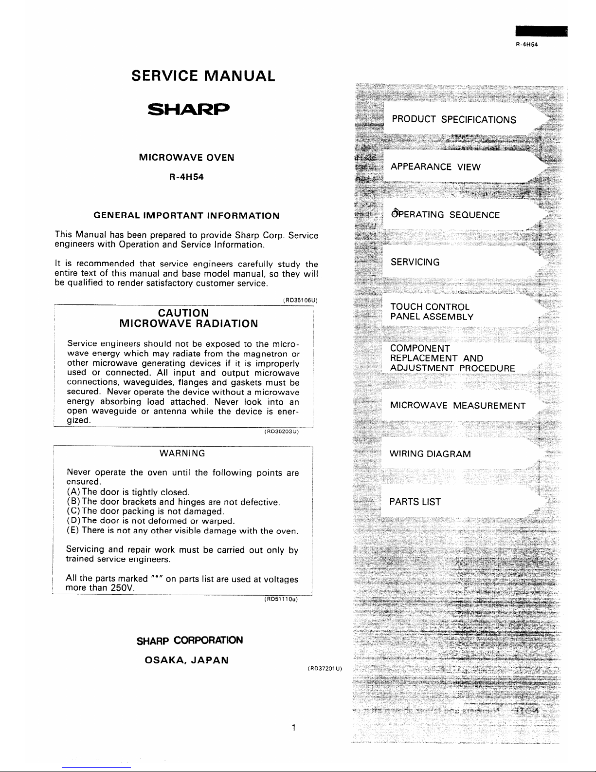
GENERAL IMPORTANT INFORMATION
This Manual has been prepared to provide Sharp Corp. Service
engineers with Operation and Service Information.
It is recommended that service engineers carefully study the
entire text of this manual and base model manual, so they will
be qualified to render satisfactory customer service.
(RD367 06U)
CAUTION
I
I
1
MICROWAVE RADIATION
I
Service engineers should not be exposed to the microwave energy which may radiate from the magnetron or
other microwave generating devices if it is improperly
used or connected. All input and output microwave
connections, waveguides, flanges and gaskets must be
secured. Never operate the device without a microwave
energy absorbing load attached. Never look into an
open waveguide or antenna while the device is ener-
gized.
(RD36203U)-
WARNING
Never operate the oven until the following points are
ensured.
(A)The door is tightly closed.
(B) The door brackets and hinges are not defect
(C)The door packing is not damaged.
(D)The door is not deformed or warped.
(E) There is not any other visible damage with tt
Servicing and repair work must be carried out
trained service engineers.
ive.
,
le oven. j
only by
All the parts marked I’*,,
on parts list are used at voltages
more than 250V.
/
I
(RDSlllOu)
SHARP CORPORATION
OSAKA, JAPAN
71jx 71jx
: -,*&-y **I : -,*&-y **I
/ /
.!. x ~ *A,, “L > Y .!. x ~ *A,, “L > Y
; “, . * * ;y ; “, . * * ;y * ^* ,a
%C %C
* ^“,i. . , - jas?-x *““I i?$.<s*,-\>i< . , - j/s-E *““I 8 7$ .“*‘w~
y 1 \..\“;. y 1 \..\“;.
* *
?k 1 ‘.,;:,:+: * ?k 1 ‘.,;:,:+: *
~~~~~~~~~~~~~~~~~~~~~ *^ , <““$y l-L, -$L. :“L * / i r ~~~~~~~~~~~~~~~~~~~~~ X^ , <““$y :: -$L. :“L * / i r
*‘w *‘w ” ”
a\ $A:;&gs: idp -y, *-$& ; ‘#*.a$&” a\ $A:;&gs: idp -y, *-$& ; ‘#*.a$&”
L “3. % 7 4 j L “3. % 7 4 j *” *”
:s& .: ‘* :s& .: ‘*
‘;*,*4 _ ‘;*,*4 _
\ \
i 4 / 2 i 4 / 2
I ‘* ~ I ‘* ~
, _ , _
^~ -$: ‘&zy& Q ‘,%‘a!. ” ,-
^~ -$: ‘&zy& Q ‘,%‘a!. ” ,-
_ ic’ _ ic’
2: ;g:: 2”r.w :,> ;g:: 2”r.w
I ‘P+<+~$,\+ , I ‘P+<+~$,\+ ,
; \
G\ I * G\ I *
.%j ‘&W&d
x*-p !r+p ;” ‘> “p,!fy j ;”
> 4.
’ “”
r\- *-i ‘&W&d
L&i&$ &&&G~ L&i&$ &&&G~
1%++ >* 1%++ >*
,z B ,z B
PRODUCT SPECIFICATIONS PRODUCT SPECIFICATIONS
,+-$“$z
:v
,+-$“$z
:v
APPEARANCE VIEW PPEARANCE VIEW
.“h‘C ”
<b%
,&r-$,-1
,
“a‘ 11”
~~~~~~~~ _
- .”
~~~~~~ \\;
A:& - +
“.&*. ~~ -I
IP
I 9 ‘3‘ ‘,*” q@w
“&Y. :
b” ‘
jj
- ;:g -&$* “X d _
c; h >a- .$y ~ .**w, .
.~~~~~~~ 4;
s>_ ” ” %.*-:
.b” .I& v.‘~ ‘K->
hi-$ _ ” *a._ ’
&>* ;\?y$$ b
1 LI cl ,L :
&&*&~, g$y- $
SERVICING
~,~I, b -
. x
1 * .+*\< c ‘;
“Pi y -?<*
y ”
a +u-
..*
* * rpg/: Je
,“~h $;*)
:+* 9b
-,r 2 A”4.*>- , s >’
,$ .\ :
\* ~ cj
. * * “,S
* * 9”” i \;a*,*
I
n* ’
* L
,;*$&a& ) -* ”
I! 2
-: Z&i -(;L,&* *\ ,
\*
. 4 s:<*I T‘“aa., “&+,,**r
“a-\
x r,
3 -?
* “ib”$ k”‘*:
TOUCH CONTROL
y- Y _
. .“) ”
’
&. e?$&+&
PANEL ASSEMBLY
F”“‘ “.
,a: I .t
7,“” . :
: d
”
4 _
j ..,“j _ *’ Y
, ”
l”fN **1‘,
x ^
I>, \-,
L
COMPONENT
1
REPLACEMENT AND
ADJUSTMENT PROCEDURE -;,sv
* -a
\
.< ”
>>
m
\ ^
OPERATING SEQUENCE
~~~~~~~~ _
- .”
A:& - +
“.&*. ~~ -I
~~~~~~ \\;
IP
I 9 ‘3‘ ‘,*” q@w
jj “&Y. :
b” ‘ - ;:g -&$* “X d _
c; h >a- .$y ~ .**w, .
.~~~~~~~ 4;
s>_ ” ” %.*-:
.b” .I& v.‘~ ‘K->
hi-$ _ ” *a._ ’
&>* ;\?y$$ b
1 LI cl ,L :
&&*&~, g$y- $
~,~I, b -
. x
SERVICING
1 * .+*\< c ‘;
“Pi y -?<*
y ”
a +u-
..*
* * rpg/: Je
,“~h $;*)
:+* 9b
-,r 2 A”4.*>- , s >’
,$ .\ :
\* ~ cj
. * * “,S
* * 9”” i \;a*,*
I
n* ’
* L
,;&‘;a& ) -* ”
-: Z&i -(;L,&* *\ ,
\*
I! 2
. 4 s:<*I T‘“aa., “&+,,**r
“a-\
x r,
3 -?
* “ib”$ k”‘*:
y- Y _
.
TOUCH CONTROL
.“) ”
’
&. e?$&+&
PANEL ASSEMBLY
F”“‘ “.
,a: I .t
7,“” . :
: d
”
4 _
j ..,“j _ *’ Y
, ”
l”fN **1‘,
x ^
I>, \-,
L
COMPONENT
1
REPLACEMENT AND
ADJUSTMENT PROCEDURE -;,sv
* -a
\
.< ”
>>
m
\ ^
:s ; &+\ I”_
MICROWAVE MEASUREMENT ’ ’
j* *> ^
*
, j” 3 ^ : .;; I< T”i
* s ” _
_ j , ) I 2 ,--
. .
*‘,I?%” ^
.\+y
Y. :
^ s <i
7” ::*p :
/ -
i:‘““n **
‘ *, I ar r
;
,I 1
sypd *“< ;>. *
WIRING DIAGRAM
/s-o* <
:s ; &+\ I”_
MICROWAVE MEASUREMENT ’ ’
j* *> ^
*
, j” 3 ^ : .;; I< ,“!
* * ” _
_ j , ) I 2 ,--
. .
*‘,I?%” ^
^ s <i
.\+y
Y. :
7” ::*p :
/ -
i:‘““n **
‘ *, I ar r
;
,I 1
sypd *“< ;>. *
WIRING DIAGRAM
/s-o* <
*f^ w\ ” >
- ‘C-c ^
i
<a .
_ i
, c
;
”
* i.
, ‘.
i
c
“: ’
““i.‘T 6, i,
* I\
PARTS LIST
: *
(RD37201 U)
1
Page 4
R-4H54
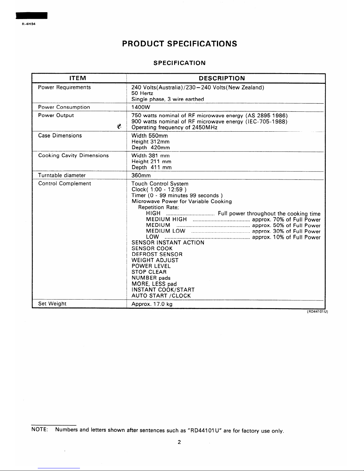
PRODUCT SPECIFICATIONS
SPECIFICATION
ITEM
I
I
DESCRIPTION
Power Requirements / 240 Volts(Australia)/230- 240 Volts( New Zealand)
/ 50 Hertz
1 Single phase, 3 wire earthed
Power Consumption / 1400w
Power Output
750 watts nominal of RF microwave energy (AS 2895 1986)
900 watts nominal of RF microwave energy (IEC-705-1988)
@ I Operating frequency of 2450MHz
Case Dimensions Width 550mm
I Height 312mm
Depth 420mm
-Cooking Cavity Dimensions
1 Width 381 mm
Height 211 mm
Depth 411 mm
Turntable diameter 360mm
Control Complement Touch Control System
Clock( I:00 - 12:59 )
Timer (0 - 99 minutes 99 seconds )
/ Microwave Power for Variable Cooking
Repetition Rate;
HIGH
. . . . . . . . . . . . . . . . . . . . . . . . . . . . . . . . .
Full power throughout the cooking time
MEDIUM HIGH
..*........*.......,..*................ approx. 70% of Full Power
MEDIUM
. . . . . . . . . . . . . . . . . . . . . . . . . . . . . . . . . . . . . . . . . . . . . . . . . .
approx. 50% of Full Power
MEDIUM LOW . . . . . . . ..*..*.....I....................* approx. 30% of Full Power
I
LOW
. ..*......................................................
/ SENSOR INSTANT ACTION
approx. 10% of Full Power
/ SENSOR COOK
1 DEFROST SENSOR
/ WEIGHT ADJUST
j POWER LEVEL
STOP CLEAR
NUMBER pads
MORE, LESS pad
Set Weight
INSTANT COOK/START
1 AUTO START /CLOCK
Approx. 17.0 kg
NOTE:
Numbers and letters shown after sentences such as “RD44101 U” are for factory use only.
2
Page 5
R-4H54
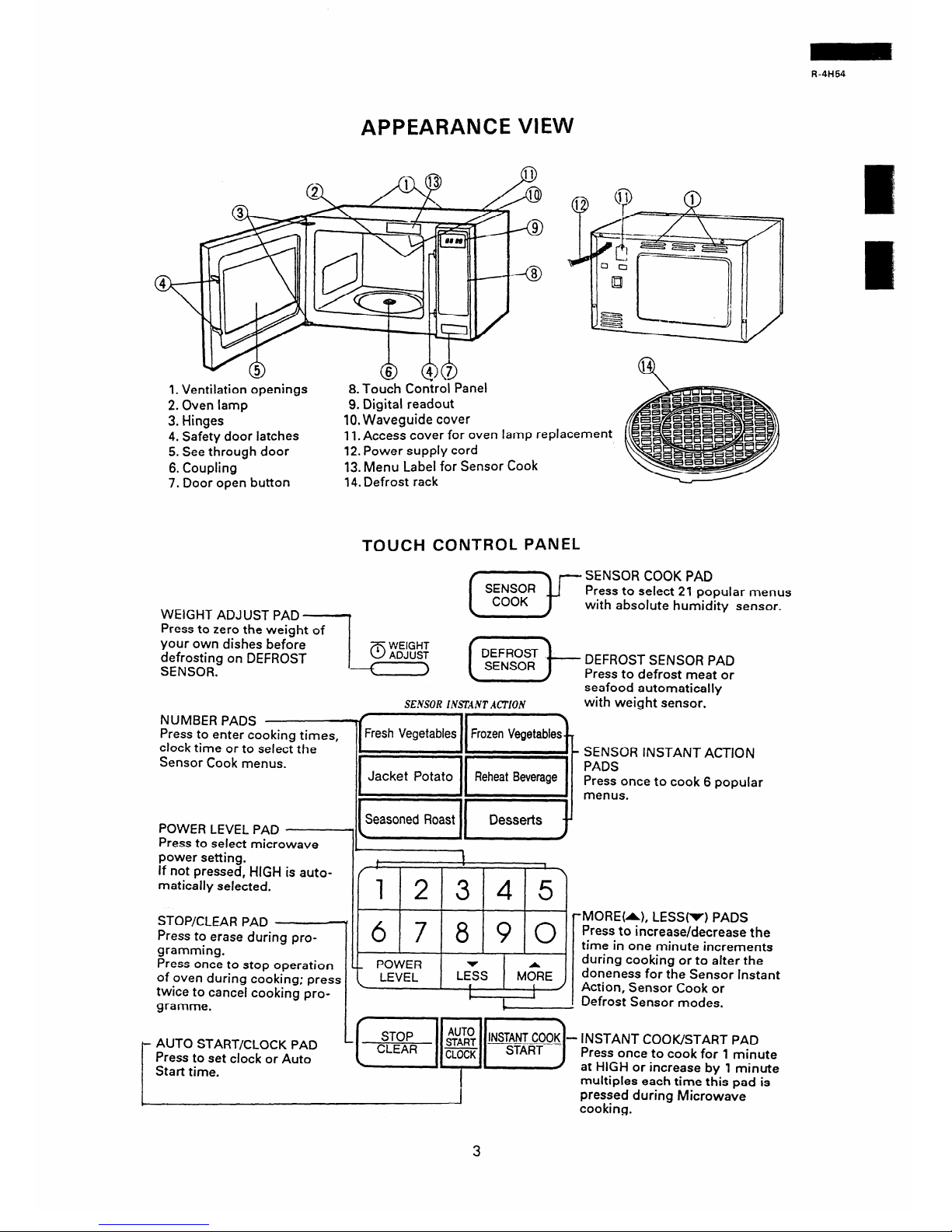
APPEARANCE VIEW
1. Ventilation openings
8. Touch Control Panel
2. Oven lamp
3. Hinges
4. Safety door latches
5. See through door
6. Coupling
7. Door
open
button
9. Digital readout
10. Waveguide cover
.
I
I
11. Access cover for oven ramp replacement
12. Power supply cord
13. Menu Label for Sensor Cook
7 4. Defrost
rack
TOUCH CONTROL PANEL
WEIGHT ADJUST PAD
1
(G-JJ-
SENSOR COOK PAD
Press to select 21 popular menus
with absolute humidity sensor.
Press to zero the weight of
your own dishes before
defrosting on DEFROST
SENSOR.
pq (q- F;;I;;;;;lF
.
SENSOR INSlliNTACTION
with weight sensor.
NUMBER PADS
Press to enter cooking times,
Fresh Vegetables Frozen Vegetables
clock time or to select the . -Sensor Cook menus.
POWER LEVEL PAD
Press to select microwave
teasoned Roast 11 Desserts y
l
power setting.
If not pressed, HIGH is auto-
t
!
F’
1
matically selected.
12345
6 7 890
STOP/CLEAR PAD
Press to erase during programming.
Press once to stop operation
of oven during cooking; press
twice to cancel cooking programme.
c_ POWER
\ LEVEL
LE:S t&?E
#
1
c
1
SENSOR INSTANT ACTION
PADS
Press once to cook 6 popular
menus.
.MORE&), LESS(r) PADS
Press to increase/decrease the
time in one minute increments
during cooking or to alter the
doneness for the Sensor Instant
Action, Sensor Cook or
Defrost Sensor modes.
AUTO START/CLOCK PAD
Press to set clock or Auto
Start time.
I
multiples each time this oad is
pressed during Microwave
cooking.
3
Page 6
R-4H54
OPERATING SEQUENCE
SENSOR COOKING CONDITION
Using the SENSOR COOK function, the foods are
cooked without figuring time, power level or quantity.
When the oven senses enough steam from the food, it
relays the information to its microprocessor which will
calculate the remaining cooking time and power level
needed for best results.
When the food is cooked, water vapor is developed.
The sensor “senses” the vapor and its resistance in-
creases gradually.
When the resistance reaches the
value set according to the menu, supplementary cooking is started.
The time of supplementary cooking is determined by
experiment with each food category and inputted into
the LSI.
An example of how sensor works:
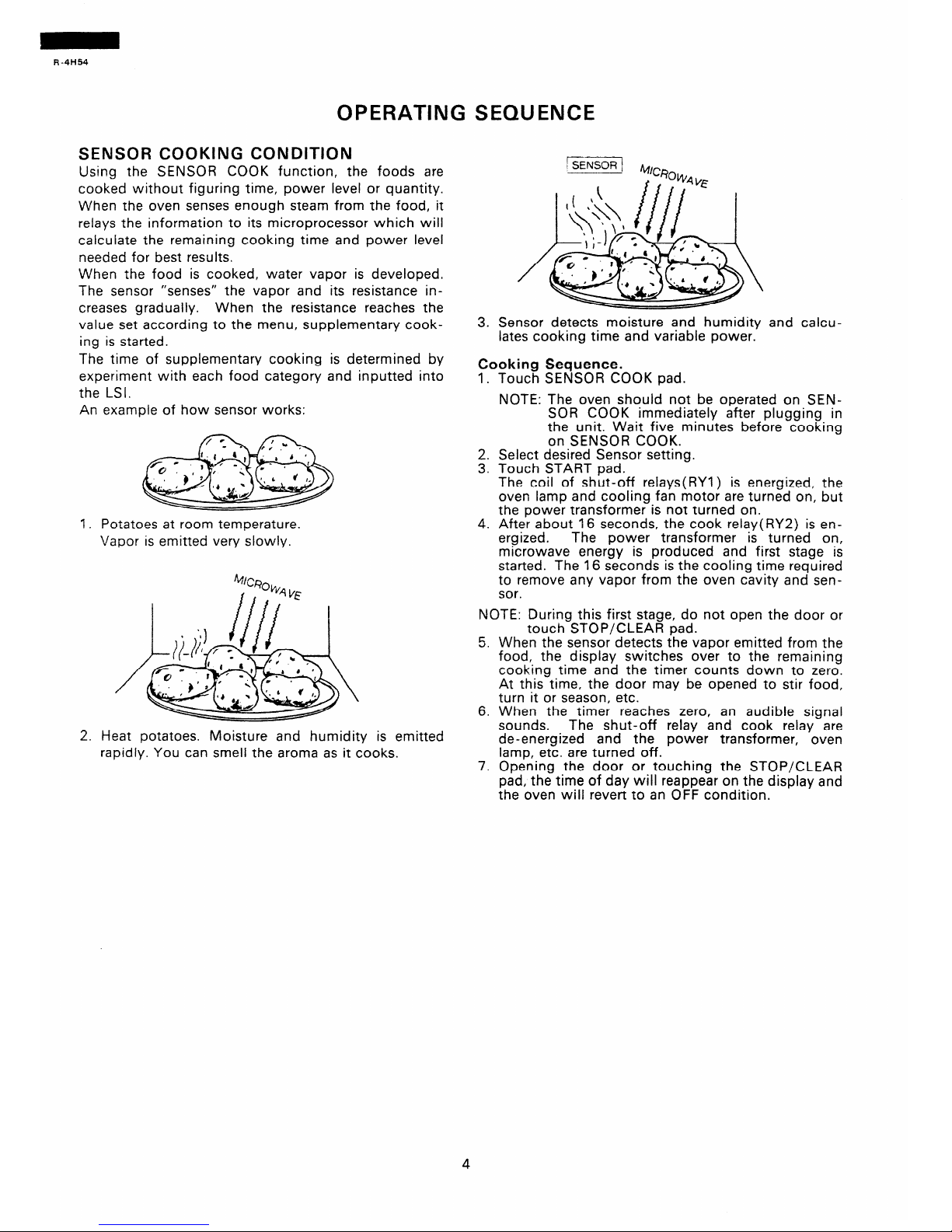
1. Potatoes at room temperature.
Vapor is emitted very slowly.
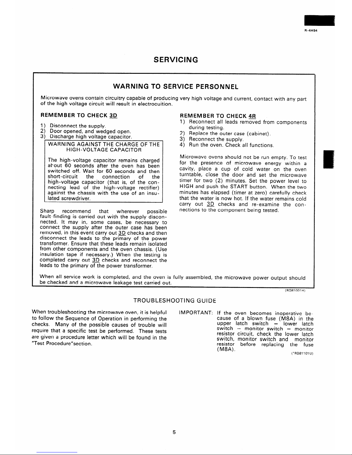
2. Heat potatoes. Moisture and humidity is emitted
rapidly. You can smell the aroma as it cooks.
3. Sensor detects moisture and humidity and calculates cooking time and variable power.
Cooking
Sequence.
1.
2.
3.
4.
Touch
NOTE.
Select
Touch
SENSOR COOK pad.
The oven should not be operated on SEN-
SOR COOK immediately after plugging in
the unit. Wait five minutes before cooking
on SENSOR COOK.
desired Sensor setting.
START pad.
The coil of shut-off relays( RYI) is energized, the
oven lamp and cooling fan motor are turned on, but
the power transformer is not turned on.
After about 16 seconds, the cook relay( RY2) is energized.
The power transformer is turned on,
microwave energy is produced and first stage is
started. The 16 seconds is the cooling time required
to remove any vapor from the oven cavity and sensor.
NOTE: During this first stage, do not open the door or
touch STOP/CLEAR pad.
5. When the sensor detects the vapor emitted from the
food, the display switches over to the remaining
cooking time and the timer counts down to zero.
At this time, the door may be opened to stir food,
turn it or season, etc.
6. When the timer reaches zero, an audible signal
sounds.
The shut-off relay and cook relay are
de-energized and the power transformer, oven
lamp, etc. are turned off.
7. Opening the door or touching the STOP/CLEAR
pad, the time of day will reappear on the display and
the oven will revert to an OFF condition.
Page 7
R-4H54
SERVICING
WARNING TO SERVICE PERSONNEL
Microwave ovens contain circuitry capable of producing very high voltage and current, contact with any part
of the high voltage circuit will result in electrocuition.
REMEMBER TO CHECK 3D
1) Disconnect the supply.
2) Door opened, and wedged open.
3) Discharge high voltage capacitor.
WARNING AGAINST THE CHARGE OF THE
HIGH-VOLTAGE CAPACITOR
The high-voltage capacitor remains charged
about 60 seconds after the oven has been
switched off. Wait for 60 seconds and then
short-circuit
the
connection of
the
high-voltage capacitor (that is, of the connecting lead of the high-voltage rectifier)
against the chassis with the use of an insulated screwdriver.
Sharp
recommend that
wherever possible
fault-finding is carried out with the supply discon-
nected. It may in, some cases, be necessary to
connect the supply after the outer case has been
removed, in this event carry out 3D checks and then
disconnect the leads to the primary of the power
transformer. Ensure that these leads remain isolated
from other components and the oven chassis. (Use
insulation tape if necessary.) When the testing is
completed carry out 3D checks and reconnect the
leads to the primary oEhe power transformer.
REMEMBER TO CHECK 4R
1) Reconnect all leads removed from components
during testing.
2) Replace the outer case (cabinet).
3) Reconnect the supply.
4) Run the oven. Check all functions.
Microwave ovens should not be run empty. To test
for the presence of microwave energy within a
cavity, place a cup of cold water on the oven
turntable, close the door and set the microwave
timer for two (2) minutes. Set the power level to
HIGH and push the START button. When the two
minutes has elapsed (timer at zero) carefully check
that the water is now hot. If the water remains cold
carry out 3D checks and re-examine the connections tothe component being tested.
When all service work is completed, and the oven is fully assembled, the microwave power output should
be checked and a microwave leakaae test carried out.
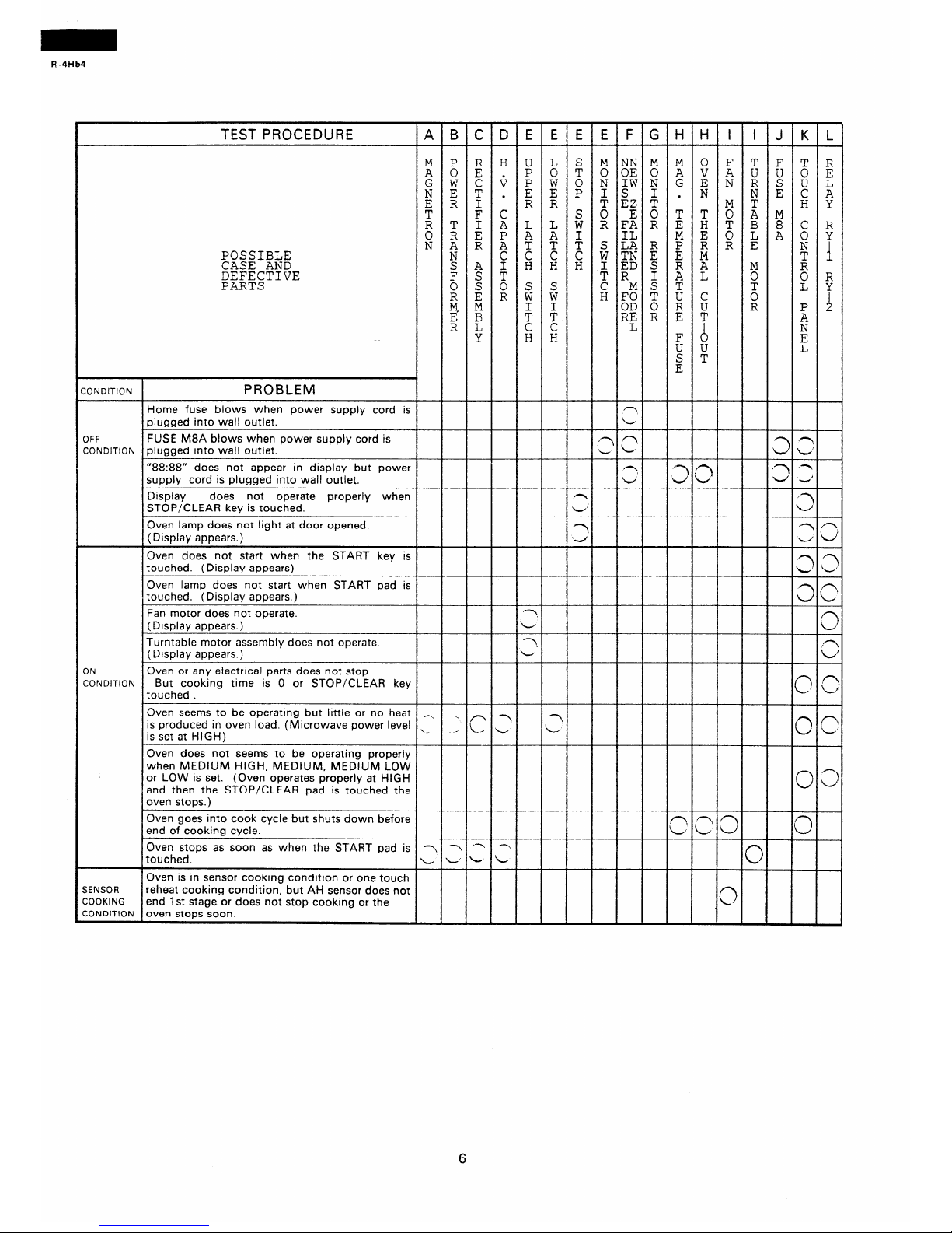
TROUBLESHOOTING GUIDE
When troubleshooting the microwave oven, it is helpful
to follow the Sequence of Operation in performing the
checks. Many of the possible causes of trouble will
require that a specific test be performed. These tests
are given a procedure letter which will be found in the
“Test Procedure”section.
IMPORTANT: If the oven becomes inoperative be-
cause of a blown fuse (M8A) in the
upper latch switch - lower latch
switch
- monitor switch - monitor
resistor circuit, check the lower latch
switch, monitor switch and
monitor
resistor
(M8A).
before replacing the fuse
(‘RD81101 U)
5
Page 8
R-4H54
TEST PROCEDURE ABCDEEEEFGHHI
I J K L
!XHUL
S MNNM M 0 F T F T R
POT OOEOAVAU U 0 E
"WC+;~;~;W~G;NRSUL
i!::- RR TEZT -
N E ii e
EOTT:;fM
;T::LL;:FAREHTB8CR
OREPAAI
NiRATTTSikRPRRE
MEoLA:Y
POSSIBLE C C C C WTNE E M
CASE AND
DEFECTIVE
S A I H H H $gD$ ;;
;f
1
F S T E
PARTS
0 s 0 s s_
R E R Y F
:F:$ ; C
z
E F
3 !z
: :
% :: ; 8
R
iI
4
R k
L
H H
E
E
(
:ONDITION PROBLEM
Home fuse blows when power supply cord is
plugged into wall outlet.
OFF FUSE M8A blows when power supply cord is
CONDITION plugged into wall outlet.
“88:88” does not appear in display but power
supply cord is plugged into wall outlet.
Display does not operate properly when
STOP/CLEAR key is touched.
Oven lamp does not light at door opened.
(Display appears.)
Oven does not start when the START key is
touched. (Display appears)
Oven lamp does not start when START pad is
touched. (Display appears.)
?
i/
;il kc-J
,y? ,-
4
f-Y
L!
3
?
In
4
L..J I/
3
z
3
/1
L
Fan motor does not operate.
?
(Display appears.}
L
c
Turntable motor assembly does not operate.
?
(Display appears.)
I
L
c
ON Oven or any electrical parts does not stop
CONDITION
But cooking time is 0 or STOP/CLEAR key
touched
c
IC
Oven seems to be operatmg but little or no heat -_,
is produced in oven load. (Microwave power level ,
--~ ,n 7
?
is set at HIGH)
/ L L
L
0
c
Oven does not seems to be operating properly
when MEDIUM HIGH, MEDIUM, MEDIUM LOW
or LOW is set. (Oven operates properly at HIGH
and then the STOP/CLEAR pad is touched the
0
z
oven stops.)
Oven goes into cook cycle but shuts down before
end of cooking cycle.
Oven stops as soon as when the START pad is 7 -Y ‘- -Y
touched.
L L’ L L
Oven is in sensor cooking condition or one touch
SENSOR reheat cooking condition, but AH sensor does not
COOKING
end 1 st stage or does not stop cooking or the
CONDITION oven stops soon.
Page 9

R-4H54
RE = Replace / CK = Check
i
5
2
L
F
i
3
N
5
B
.
5
ft
:
!z
::
-
-
-
-
-
-
-
-
-
-
-
-
-
-
m
4
ii?
-
:
i
R
!
E
Y
!
D
r
L
-
r
L
-
-
-
-
-
-
-
-
RE
:
i
ii
P
tJ
D
5
:
F
-
--
-
A
u
-
<
d
-
-
-
-
-
-
-
-
-
-
c
-
n
u
-
z
iii
::
B
Y
ER
E
5
z
c
z
u
-
-
-
-
-
-
2
E
:
5
ik
D
Y
E
i!
i
E
-
-
C
c
c
c
z
__
c
3
-
c
-
-
-
c
-
CK
-
OH
ii
6
E
8
ii
:
h
r
L
rL
-
-
-
-
-
-
-
-
-
Fit
-
W
!
G
0
Ep
i
I
ifi
-
-
-
-
-
-
-
c
-
-
-
-
-
C
-
P
'u
__
(3
-
n
‘U
A
u
__
-
-
-
5
i
ii
Ei
6
:
i
F
i
-
-
-
n
u
-
-
E
g
3
%
;
F
i
k
d
N
-
__
-
-
-
~
c
-
-
-
-
-
-
-
-
-
-
-
-
-
-
-
-
-
-
-
-
-_
-
-
-
-
-
-
-
-
-
-
-
-
-
-
-
-
-
-
-
-
-
-
-
-
-
-
-
-
-
-
-
-
-
-
-
-
-
-
-
-
-
-
-
-
-
-
-
7
Page 10
R-4H54
TEST PROCEDURES
PROCEDURE
LETTER
COMPONENT TEST
MICROWAVE OUTPUT POWER (2 LITRE WATER LOAD)
The following test procedure should be carried out with the microwave oven in a fully assembled
condition (with outer case fitted). Microwave output power from the magnetron can be measured
by way of substitution, i.e. it can be measured by using a water load how much it can be absorbed
by the water load. To measure the microwave output power in the microwave oven, the relation
of calorie and watt is used. On the other hand, if the temperature of the water with V(ml) rises
AT (“C) during this microwave heating period, the calorie of the water is V x AT.
The formula is as follows;
P
8330 x AT
=
t
, Our condition for the water load is as follows:
/
Room temperature
. . . . . . . . . . . . . . . . . . . . . . . . . . . . 23+2X
Power supply Voltage I . ..- . . . . . . . . . Rated voltage
Water load
. . . ...2000 ml
i
Initial temperature
. . . . . . . 23 +I “C
Heating time . . . . . . 1 min. 51
sec.
P = 75 x AT
1
I
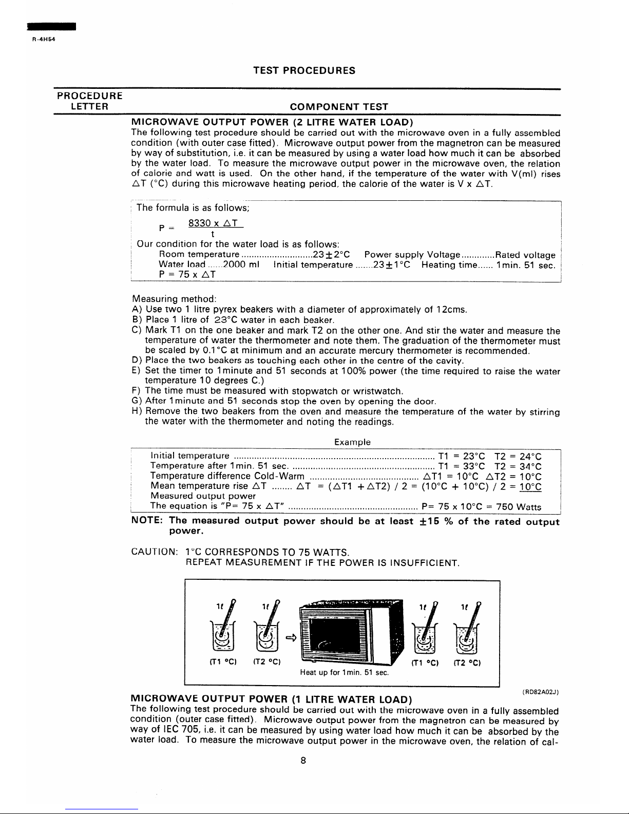
Measuring method:
A) Use two 1 litre Pyrex beakers with a diameter of approximately of 12cms.
B) Place 1 litre of 23°C water in each beaker.
C) Mark Tl on the one beaker and mark T2 on the other one. And stir the water and measure the
temperature of water the thermometer and note them. The graduation of the thermometer must
be scaled by 0.1 “C at minimum and an accurate mercury thermometer is recommended.
D) Place the two beakers as touching each other in the centre of the cavity.
E) Set the timer to 1 minute and 51 seconds at 100% power (the time required to raise the water
temperature IO degrees C.)
F) The time must be measured with stopwatch or wristwatch.
G) After 1 minute and 51 seconds stop the oven by opening the door.
H) Remove the two beakers from the oven and measure the temperature of the water by stirring
the water with the thermometer and noting the readings.
Example
Initial temperature . . . . . . . . . . ..*....................*........................................*....
Tl = 23°C T2 = 24°C
Temperature after 1 min.
51
sec. . . . . . . . . . . . . . . . . . . . . . . . . . . . . . . . . . . . . . . . . . . . . . . . . . . . . . . . . Tl
= 33°C T2 = 34°C
Temperature difference
Cold-Warm . . . . . . . . . . . . . . . . . . . . . . . . . . . . . . . . . . . . . . . . . . . AT1 = 10°C AT2 =
10°C
Mean temperature rise AT
. . . . . . . .
AT = (AT1 +AT2) / 2 = (10°C + IO’C) / 2 = 10°C
Measured output power
The equation
is “P=
75 x
AT” . . . . . . . . . . . . . . . . . . . . . . . . . . . . . . . . . . . . . . . . . . . . . . . . . . .
P=
75 x 10°C = / 750 Watts
NOTE: The measured output power should be at least +I5 % of the rated output
power.
CAUTION: 1 “C CORRESPONDS TO 75 WATTS.
REPEAT MEASUREMENT IF THE POWER IS INSUFFICIENT.
m OC)
IT2 OCt
Tr2 OC)
Heat up for 1 min. 51 sec.
MICROWAVE OUTPUT POWER (1 LITRE WATER LOAD)
(RD82A02J)
The following test procedure should be carried out with the microwave oven in a fully assembled
condition (outer case fitted). Microwave output power from the magnetron can be measured by
way of IEC 705, i.e. it can be measured by using water load how much it can be absorbed by the
water load. To measure the microwave output power in the microwave oven, the relation of cal-
8
Page 11
R-4H54
TEST PROCEDURES (CONT’D)
PROCEDURE
LETTER
COMPONENT TEST
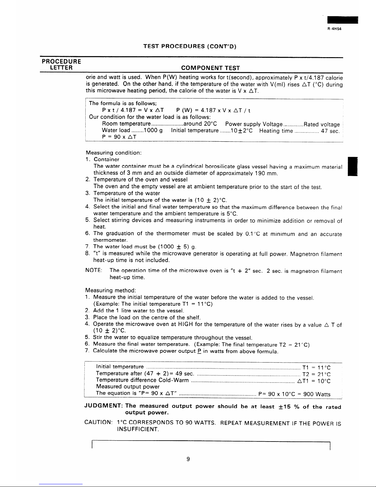
orie and watt is used. When P(W) heating works for t(second), approximately P x t/4.1 87 calorie
is generated. On the other hand, if the temperature of the water with V(ml) rises AT (“C) during
this microwave heating period, the calorie of the water is V x AT.
I
/ The formula is as follows;
I
Pxt/4.187=VxAT P(W)=4.187xVxAT/t
/ Our condition for the water load is as follows:
I
Room temperature . . . . . . . . . . . . . . . . . . . . . around
20°C
Power supply Voltage .- . . . . . . . . . . . Rated
voltage
/
Water load . . . . . . . . 1000
g
Initial temperature . . . . . . . IO f2”C
Heating time . . . . . . . . . . . . . . . . 47 sec.
I
P=90xAT
Measuring condition:
1. Container
The water container must be a cylindrical borosilicate glass vessel having a maximum material
thickness of 3 mm and an outside diameter of approximately 190 mm.
2. Temperature of the oven and vessel
The oven and the empty vessel are at ambient temperature prior to the start of the test.
3. Temperature of the water
The initial temperature of the water is (10 & 2)“C.
4. Select the initial and final water temperature so that the maximum difference between the final
water temperature and the ambient temperature is 5°C.
5. Select stirring devices and measuring instruments in order to minimize addition or removal of
heat.
6. The graduation of the thermometer must be scaled by 0.1 “C at minimum and an accurate
thermometer.
7. The water load must be (1000 + 5) g.
8. “t” is measured while the microwave generator is operating at full power. Magnetron filament
heat-up time is not included.
NOTE: The operation time of the microwave oven is “t + 2” sec. 2 sec. is magnetron filament
heat-up time.
Measuring method:
1. Measure the initial temperature of the water before the water is added to the vessel.
(Example: The initial temperature Tl = 11 “C)
2. Add the 1 litre water to the vessel.
3. Place the load on the centre of the shelf.
4. Operate the microwave oven at HIGH for the temperature of the water rises by a value A T of
(10 f: 2)“C.
5. Stir the water to equalize temperature throughout the vessel.
6. Measure the final water temperature. (Example: The final temperature T2 = 21 “C)
7. Calculate the microwave power output p in watts from above formula.
I
I
I
Initial temperature . . . . . . . . . . . . . . . . . . . . . . . . . . . . . . . . . . . . . . . . . . . . . . . . . . . . . . . . . . . . . . . . . . . . . . . . . . . . . . . . . . . . . . . . . . . . . . . . . . . . .
Tl = 1 1 “C
/
I
Temperature after (47 + 2)= 49 sec.
. . . . . . . . . . . . . . . . . . . . . . . . . . . . . . . . . . . . . . . . . . . . . . . . . . . . . . . . . . . . . . . . . . . .
T2 = 21 “C
I
Temperature difference Cold-Warm
. . . . . . . . . . . . . . . . . . . . . . . . . . . . . . . . . . . . . . . . . . . . . . . . . . ..*...............
AT1 = 10°C
Measured output power
The equation is “P= 90 x AT” . . . . . . . . . . . . . . . . . . . . . . . . . . . . . . . . . . . . . . . . . . . . . . . . . . .
P= 90 x 10°C = 900 Watts
JUDGMENT: The measured output power should be at least +15 % of the rated
output power.
CAUTION: 1°C CORRESPONDS TO 90 WATTS. REPEAT MEASUREMENT IF THE POWER IS
INSUFFICIENT.
9
Page 12
R-4H54
TEST PROCEDURES (CONT’D)
PROCEDURE
LETTER
COMPONENT TEST
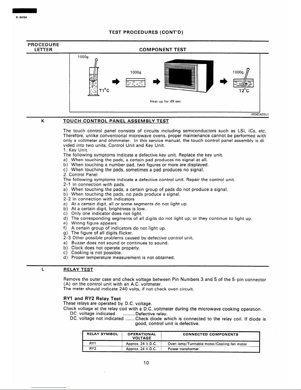
T2”C
Heat up for 49 sec.
TOUCH CONTROL PANEL ASSEMBLY TEST
The touch control panel consists of circuits including semiconductors such as LSI, ICs, etc.
Therefore, unlike conventional microwave ovens, proper maintenance cannot be performed with
only a voltmeter and ohmmeter.
In this service manual, the touch control panel assembly is di-
vided into two units, Control Unit and Key Unit.
1. Key Unit.
The following symptoms indicate a defective key unit. Replace the key unit.
a) When touching the pads, a certain pad produces no signal at all.
b) When touching a number pad, two figures or more are displayed.
c) When touching the pads, sometimes a pad produces no signal.
2. Control Panel
The following symptoms indicate a defective control unit. Repair the control unit.
2-l In connection with pads.
a) When touching the pads, a certain group of pads do not produce a signal.
b) When touching the pads, no pads produce a signal.
2-2 In connection with indicators
a) At a certain digit, all or some segments do not light up.
b) At a certain digit, brightness is low.
c) Only one indicator does not light.
d) The corresponding segments of all digits do not light up; or they continue to light up.
e) Wrong figure appears.
f) A certain group of indicators do not light up.
g) The figure of all digits flicker.
2-3 Other possible problems caused by defective control unit.
a)
Buzzer does not sound or continues to sound.
b) Clock does not operate properly.
c) Cooking is not possible.
d) Proper temperature measurement is not obtained.
RELAY TEST
Remove the outer case and check voltage between Pin Numbers 3 and 5 of the 5-pin connector
(A) on the control unit with an A.C. voltmeter.
The meter should indicate 240 volts, if not check oven circuit.
RYI and RY2 Relay Test
These relays are operated by D.C. voltage.
Check voltage at the relay coil with a D.C. voltmeter during the microwave cooking operation.
DC. voltage indicated
. . . . . . . . . . Defective
relay.
DC. voltage not indicated . . . . . . ..Check diode which is connected to the relay coil. if diode is
good, control unit is defective.
.
RELAY SYMBOL j OPERATIONAL
CONNECTED COMPONENTS
I
VOLTAGE
RYl
/ Approx. 24 V.D.C. / Oven lamp/Turntable motor/Cooling fan motor
RY2
1 ADDrOX. 24 V.D.C. - I Power transformer
10
Page 13

R-4H54
TEST PROCEDURES (CONT’D)
PROCEDURE
LETTER COMPONENT TEST
M PROCEDURES TO BE TAKEN WHEN THE FOIL PATTERN ON THE PRINTED WIRING
BOARD (PWB) IS OPEN.
To protect the electronic circuits, this model is provided with a fine foil pattern added to the
primary on the PWB, this foil pattern acts as a fuse. If the foil pattern is open, follow the troubleshooting guide given below for repair.
Problem: POWER ON, indicator does not light up.
ISTEPS j
OCCURENCE
,
CAUSE OR CORRECTION
/
i 1
/The rated voltage is not applied to POWER terminal / Check supply voitage and oven main unit.
/
I
: of CPU connector (CN-A)
I
I 2
j The rated voltage is applied to primary side of power ’ Power transformer or secondary circuit defective. :
t
transformer.
Check and repair.
i 3 j Only pattern at “a” is broken.
/ *Insert jumper wire Jl and solder.
/ 4
/ Pattern at “a” and “b” are broken.
/ ‘Insert the coil RCILF2003YAZZ between “c” and
/
I
/ “d”,
NOTE:* At the time of these repairs, make a visual in-
spection of the varistor for burning damage
and examine the transformer with tester for the
presence of layer short-circuit (check primary
coil resistance).
If any abnormal condition is detected, replace
the defective parts.
N
WEIGHT SENSOR ASSEMBLY AND IC3(MEMORY) TEST.
After replacing the weight sensor, turntable, control unit, turntable motor, or
IC3, carry out the following procedure in order to calibrate the weight sensor.
If the weinht sensor is not recalibrate. the food may be over or under cooked.
The following procedure should be carried out with microwave oven in a fully assembled condition (with outer case fitted).
1. Test Method
(1)
Place the turnrable on the turntable support plate correctly, and close the door.
(2) Plug the oven into a power point. (“88:88” will appear on the display.)
(3) Press the STOP/CLEAR pad. (Display shows M : ” with sound of buzzer.)
(4) Press the AUTO START/CLOCK pad. (Display shows “
0” with sound of buzzer.)
(5) Press the DEFROST SENSOR pad. (Display shows M
0~)
(6) Press the POWER LEVEL pad. (Display shows ”
On.)
(7) Press the INSTANT COOK/START pad. (Display shows w TEST” with sound of
buzzer.)
(8)
Press the “4” of number pads. (Display shows M
4“ with sound of buzzer, and tuntable
and oven lamps come on.)
(9) After 56 seconds, make sure that the display shows “00055 - 00250”11 with sound
of buzzer.
If display shows less than 00055 or more than 00250, weight sensor is defect.
(10) Place the weight 1.3 kg+1 % (water load 1.3 kg+1 %) on the turntable.
(11) Press the “6” of number pads. (Display shows ”
turntable and oven lamps come on.)
6” with sound of buzzer, and
(12) After 56 seconds, make sure that the display shows “00030 - 00200”” with sound
of buzzer.
11
Page 14

R-4H54
TEST PROCEDURES (CONT’D)
PROCEDURE
LETTER
COMPONENT TEST
If display shows less than 00030 or more than 00200, weight sensor is defect.
(13) Disconnect the oven from power supply, and repeat above procedure items 1 to 7
(14) Press the “7” of number pads, and make sure that the display shows “00030 -
00200” I’.
If display shows less than 00030 or more than 00200, lC3 is defect.
(15) Press the STOP/CLEAR pad. (Display shows “”
: ” with sound of buzzer.)
(16) impose 1.3 kg load on the defrosting rack and place it in the oven cavity. Touch the
“DEFROST SENSOR” pad. After approx. 56 seconds, time display appears.
2. Acceptance Standard.
(1) Under 1.3 kg load : 32 min 22 sec. +242 sec.
AH SENSOR TEST
Checking the initial sensor cooking condition
(1) The oven should be plugged in at least five minutes before sensor cooking.
(2) Room temperature should not exceed 95”F(35”C).
(3) The unit should not be installed in any area where heat and steam are generated. The unit
should not be installed, for example, next to a conventional surface unit. Refer to the
“INSTALLATION Instructions”.
(4) Exhaust vents are provided on the back of the unit for proper cooling and air flow in the
cavity.To permit adequate ventilation, be sure to install so as not to block these vents.
There should be some space for air circulation.
(5) Be sure the exterior of the cooking container and the interior of the oven are dry. Wipe off
any moisture with a dry cloth or paper towel.
(6) The Sensor works with food at normal storage temperature.For example, chicken pieces
would be at refrigerator temperature and canned soup at room temperature.
(7) Avoid using aerosol sprays or cleaning solvents near the oven while using Sensor settings.
The sensor will detect the vapor given of by the spray and turn off before food is properly
cooked.
(8) After about 41 minutes if the sensor has not detected the vapor of the food, ERROR will
appear and the oven will shut off.
Water load cooking test
Make sure the oven has been plugged in at least five minutes before checking sensor cook op-
eration. The cabinet should be installed and screws tightened.
(1) Fill approximately 200 milliliters (7.2 oz) of tap water in a 1000 miliiliter measuring cup.
(2) Place the container on the center of tray in the oven cavity.
(3) Close the door.
(4) Touch SENSOR COOK pad and number pad 1 .Now, the oven is in the sensor cooking
condition and SC-l will appear in the display.
(5) Touch Start pad.The oven will operate for the first 16 seconds, without generating micro-
wave energy.
NOTE: ERROR will appear if the door is opend or STOP/CLEAR pad is touched during first
stage of sensor cooking.
(6) After approximately 16 seconds, microwave energy is produced, oven should turn off when
water is boiling (bubling).
If the oven does not turn off, replace the AH sensor or check the control unit, refer to explanation below:
TESTING METHOD FOR AH SENSOR AND/OR CONTROL UNIT
To determine if the sensor is defective, the simplest method is to replace it with a new replacement sensor.
(1) Disconnect oven from power supply and remove outer case.
(2) Discharge the high voltage capacitor.
(3) Remove the AH sensor.
(4) Install the new AH sensor.
(5) Re-install the outer case.
12
Page 15

R-4H54
TEST PROCEDURES (CONT’D)
PROCEDURE
LETTER
COMPONENT TEST
(6) Reconnect the oven to the power supply and check the sensor cook operation proceed as
follows:
6-l. Fill approximately 200 milliliters (7.2 oz) of tap water in a 1000 milliliter measuring cup.
6-2. Place the container on the center of tray in the oven cavity.
6-3. Close the door.
6-4. Touch SENSOR COOK pad and number 1 pad.
6-5. Touch Start pad. The control panel is in automatic Sensor operation.
6-6. The oven will turn off automatically when the water is boiling (bubling).
If new sensor dose not operate properly, the problem is with the control unit.
CHECKING CONTROL UNIT
(I) Disconnect oven from power supply and remove outer case.
(2) Discharge the high voltage capacitor.
(3) Disconnect the wire leads from the cook relay.
(4) Disconnect the sensor connector that is mounted to lower portion of control panel.
(5) Then connect the dummy resistor circuit (see fig.) to the sensor connector of control panel.
(6) Reconnect the oven to the power supply and check the sensor cook operation proceed as
follows:
6-l. Touch SENSOR COOK pad and number 1 pad.
6-2. The control panel is in the sensor cooking operation.
6-3. After approximately 20 seconds, push plunger of select switch.
This condition is same as judgement by AH sensor.
6-4. After approximately 3 seconds, cooking operation turns off, an audible signal will
sound, and the display will then revert to the time of day.
If the above is not the case, the control unit is probably defective.
If the above is proper, the AH sensor is probably defective.
PLUNGER
To Connector (F)
on Control Unit
NC
NO
F-l F-2- ccr
Rl,R2: 22f2 f 1% l/2W
R3 : 10kR + 5% 1/4W
R4: IMR + 5% l/4W
Sensor Dummy Resistor Circuit
13
Page 16

R-4H54
TOUCH CONTROL PANEL ASSEMBLY
OUTLINE OF TOUCH CONTROL PANEL
The touch control section consists of the following
units as shown in the touch control panel circuit.
(1) Key Unit
(2) Control Unit
The principal functions of these units and the signals
communicated among them are explained below.
Key Unit
The key unit is composed of a matrix, signals generated
in the LSI are sent to the key unit through
B2,B3,B5,86,B7,GO and Gl.
When a key pad is touched, a signal is completed
through the key unit and passed back to the LSI
through RO-R3 to perform the function that was requested.
Control Unit
Control unit consists of LSI, power source circuit,
synchronizing signal circuit, ACL circuit, buzzer circuit,
temperature measurement circuit, reheat sensor circuit
and indicator circuit.
1)
2)
LSI
This LSI controls the temperature measurement
signal, reheat sensor signal, key strobe signal, relay
driving signal for oven function and indicator signal.
(RD916Al U)
Power Source Circuit
This circuit generates voltage necessary in the
control unit.
Symbol Voltage Application
VC
-5.ov
LSI (ICI ), ACL circuit
VP -26V Fluorescent display tube : Grid
and anode voltage
VFl
3Vac Filament of fluorescent display
tube
VF2
(VFI to VF2 voltage)
3)
4)
5)
6)
7)
8)
Synchronizing Signal Circuit
The power source synchronizing signal is available
in order to compose a basic standard time in the
clock circuit.
It accompanies a very small error because it works
on commercial frequency.
(RD918AZU)
ACL Circuit
A circuit to generate a signal which resets the LSI
to the initial state when power is supplied.
(RD919A4U)
Buzzer Circuit
The buzzer responds to signals from the LSI to
emit noticing sounds (key touch sound and completion sound).
(RDSlAAl U)
Reheat Sensor Circuit
This circuit detects moisture of a food which is
cooking,to allow its automatic cooking.
Stop Switch
A switch to “tell” the LSI if the door is open or
closed.
Relay Circuit
To drive the magnetron, fan motor, turntable motor
and light the oven lamp.
Indicator Circuit
Indicator element is a Fluorescent Display.
Basically, a Fluorescent Display is a triode having
a cathode, a grid and an anode. Usually, the cathode of a Fluorescent Display is directly heated and
the filament serves as cathode.
The Fluorescent Display has 6-digits, 13-segments
are used for displaying figures.
10)Weight Sensor Circuit
The circuit measures the weight of food by
piezo-electric device.
14
Page 17

R-4H54
DESCRIPTION OF LSI
LSI( IZA431 DR)
The l/O signals of the LSl(lZA431 DR) are detailed in the following table.
PIN NO. 1 1
SIGNAL / VSS
I
I/O
i IN
Power source voltace: -5V
VC voltage of power source circuit input.
PIN NO. / 2
f SIGNAL j VASS 1 I/O j IN
Reference voltarre inDut terminal.
A reference voltage applied to the A/D converter in the LSI. The reference voltage is generally maintained at -5V.
PIN NO. ! 3
1 SIGNAL ! VREF
I
I/O
1 IN
Reference voltage input terminal.
A reference voltage applied to the A/D converter in the LSI. Connected to GND.(OV)
(RD93GA6U)
PIN NO.
j 4
1 SIGNAL 1 A0
I
I/O
Terminal to change functions according to the model.
Signal in accordance with the model in operation is applied to set up its function.
IN
(RD93JAl U)
PIN NO.
i 5-7
1 SIGNAL / Al-A3
I
I/O
IN
Heatinq constant compensation terminal.
(RD93GA7U)
PIN NO. / 8
1 SIGNAL / A4
I
I/O ~ IN
Input signal which communicates the door open/close information to LSI.
Door closed; “H” level signal( OV). / Door opened; “L” level signal( -5V).
(RD937A2Uj
PIN NO. 1 9 1 SIGNAL j A5
I
l/O
j IN
WEIGHT sensor input.
This input is an analog input terminal from the WEIGHT sensor circuit, and connected to the A/D converter built
into the LSI.
PINNO. / 10 1 SIGNAL j A6
I l/O
1 IN
AH sensor input.
This input is an analog inpu? terminal from the AH sensor circuit, and connected to the A/D converter built into the
LSI.
(RD936A2U)
PIN NO.
j 11
1 SIGNAL j A7
I
I/O
/ IN
Used for initial balancing of the bridge circuit(absolute humidity sensor). This input is an analog input terminal
from the AH sensor circuit, and connected to the A/D converter built into the LSI.
PINNO. / 12
1 SIGNAL i RESET
I
I/O
1 IN
Auto clear terminal,
Signal is input to reset the LSI to the initial state when power is applied. Set to “L” level the moment power is
applied, at this time the LSI is reset. Thereafter set at “H” level.
(RD93MA4U)
PIN NO. 1 13-14
Terminal not used.
1 SIGNAL 1 EO-El
I
I/O
/ OUT
15
Page 18

PIN NO. : 15 1 SIGNAL j INTI
I
I/O
i IN
,
Signal to svnchronize LSI with commercial power source frequency.
This is the basic timing for all real time processing of LSI.
J7-r-IGND
c 20mK. -i---- LI-5V)
PIN NO. i 16
1 SIGNAL j E3
I
I/O
i OUT
Magnetron Hiah-voltage circuit drivincl signal.
To turn on and off the cook relay(RY2). In HIGH operation, the signals holds “L” level during microwave cooking
and “H” level while not cooking. In other cooking modes (M.HIGH,MED,M.LOW,LOW) the signal turns to “H”
level and “L” level in repetition according to the power level.
VARI-MODE
HIGH
(100% power)
M.HIGH
(approx 70% power)
MED
(approx.5096 power)
M.LOW
(approx.30% power)
LOW
(approx.lO% power)
ON TIME OFF TIME
32sec.
Osec
24sec.
8sec.
18sec 14sec.
12sec. 20sec.
Gsec. 26sec.
PIN NO. I 17-21
1 SIGNAL / CO-C4
I
I/O
/ OUT
Used for initial balancing of the bridge circuit(absolute humidity sensor)
PIN NO.
22-23 1 SIGNAL
/ C5-C6
Used for initial balancing of the bridge circuit (WEIGHT SENSOR).
I
I/O
1 OUT
PIN NO.
24 1 SIGNAL ; C7
I
I/O
j OUT
Oven lamp driving signal (Square waveform: 50Hz).
To turn on and off shut-off relay( RYI ). The square waveform voltage is delivered to the relay( RYI ) driving circuit
and relay (RY2) control circuit.
PIN NO.
; 25 1 SIGNAL j HO
I
I/O
i IN
Signal coming from touch key.
When any one of G-l 2 line keys on key matrix is touched, a corresponding signal from B2,B3,85,B6,B7,GO and
Gl will be input onto HO. When no key is touched, the signal is held at “L” level.
PIN NO.
/ 26
1 SIGNAL / HI
I
I/O 1 IN
Sinnal similar to HO.
When any one of G-l 1 line keys on key matrix is touched, a corresponding signal will be input into HI.
PIN NO. j 27
Signal similar to HO.
1 SIGNAL / H2
I
I/O
i IN
When any one of G-IO line keys on key matrix is touched, a corresponding signal will be input into H2.
16
Page 19

R-4H54
PIN NO. / 28 SIGNAL i H3
I
l/O I IN
Sianal similar to HO.
When any one of G-9 line keys on key matrix is touched, a corresponding signal will be input into H3.
PIN NO. / 29
t SIGNAL / H4
I I/O
1 OUT
Digit selection signal.
The relation between digit signal and digit are as follows:
Digit signal
Digit
H4 . . . . . . . . . . . . . . . . . . . . . . . . . . . . . . . . . . . . . . . . . . . . . . . . . . . . . . . . . . . . . .
1 st.
H5 . . . . . . . . . . . . . . . . . . . . . . . . . . . . . . . . . . . . . . . . . . . . . . . . . . . . . . . . . . . . .
2nd.
H6 3rd.
- --------- -- --_- GND
. . . . . . . . . . . . . . . . . . . . . . . . . . . . ..*.............*.................
H4
H7
- 26V
. . . . . . . . . . . . . . . . . . . . . . . . . . . . . . . . . . . . . . . . . . . . . . . ..*............
4th.
FO
. . . . . . . . . . . . . . . . . . . . . . . . . . . . . . . . . ..*.........*.**.............
5th.
H5 n
BO,Bl
. . . . . . . . . . . . . . . . . . . . . . . . . . . . . . . . . . . . . . . . . . . . . . . . . . . . . . . .
6th.
H6 n
Normally, one pulse is output in every 13 period, and
input to the Fluorescent Display.
H7 n
FO n
Bl .BO
GNG
- 26V
PIN NO. 1 30-32 1 SIGNAL j H5-H7
Digit selection signal. Signal similar to H4.
I
I/O
j OUT
(RD938A2U)
PIN NO.
/ 33
1 SIGNAL / VPP
I
I/O
1 IN
Anode (segment) of Fluorescent Displav light-up voltaqe: -26V.
Vp voltage of power source circuit input.
(RD93GA8IJ)
PIN NO. 1 34
/
1 SIGNAL i FO
Diait selection signal. Signal similar to H4.
I
l/O
j OUT
CRD938A2U)
PIN NO.
j 35-36 1 SIGNAL / BO-Bl
I
I/O
; OUT
Dinit selection signal. Signal similar to H4.
(RD938A2U)
PIN NO.
/ 37
1 SIGNAL / 82
Segment data signals.
The relationship between signals and indicators are as follows:
I
I/O
OUT
Signal
Segment Signal
B2
Segment
. . . . . . . . . . . . . . . ..*....*.................... LB GO *.................................a........... f
EE
. . . . . . . . . . . . . . . . . . . . . . . . . . . . . . . . . . . . . . . . . . UB
B7 . . . . . . . . . . . . . . . . . . . . . . . . . . . . . . . . . . . . . . . . . . . . . e
. . . . . . . . . . . . . . . . . . . . . . . . . . . . . . . . . . . . . . . . . . . . . k B6 . . . . . . . . . . . . . . . . . . . . . . . . . . . . . . . . . . . . . . . . . . . . .
d
:i . . . . . . . . . . . . . . . . . . . * . . . . . . . . . . . . . . . . . . . . . . . . . .
-
. . . . . . . . . . . . . . . . . . . . . . . . . . . . . . . . . . . . . . . ...*...
!
B5 . . . . . . . . . . . . . . . . . . . . . . . . . . . . . . . . . . . . . . . . . . . . .
c
~~“““““‘.“‘.““‘.....“““.““.“““’
b
G2 . . . . . . . . . . . . . . . . . . . . . . . . . . . . . . . . . . . . . . . . . . . . . h
. . . . . . . . . . . . . . . . ..a..........................
a
Gl
. . . . . . . . . . . . . . . . . . . . . . . . . . . . . . . . . . . . . . . . . . . . .
g
Kev strobe siqnal.
Signal applied to touch-key section.
A pulse signal is input to HO-H3 terminal while one of G-l line keys on key matrix is touched.
PIN NO. 1 38
Segment data sianal.
Signal similar to 82.
1 SIGNAL / B3
I
I/O
/ OUT
Kev strobe signal.
Signal applied to touch-key section. A pulse signal is input to HO-H3 terminal
while one of G-2 line keys on key matrix is touched.
(RD939A3U)
17
Page 20

R-4H54
PIN NO. i 39
1 SIGNAL / B4
1 I/O / OUT
Segment data signal. Signal similar to 82.
PIN NO.
/ 40
Segment data signal.
Signal similar to 82.
1 SIGNAL i B5
I
I/O
/ OUT
Kev strobe signal.
Signal applied to touch-key section. A pulse signal is input to HO-H3 terminal
while one of G-4 line keys on key matrix is touched.
(RD939A3U)
PIN NO. 41
1 SIGNAL / B6 1 I/O / OUT
Segment data signal.
Signal similar to B2.
Kev strobe siqnal.
Signal applied to touch-key section. A pulse signal is input to HO-H3 terminal
while one of G-5 line keys on key matrix is touched.
(RD939A3U)
PIN NO.
j 42
Segment data siqnal.
Signal similar to B2.
] SIGNAL j B7
I
I/O
j OUT
Kev strobe signal.
Signal applied to touch-key section. A pulse signal is input to HO-H3 terminal
while one of G-6 line keys on key matrix is touched.
(RD939A3U)
PIN NO. j 43
Segment data signal.
Signal similar to B2.
1 SIGNAL j GO
I
I/O
I OUT
Kev strobe sinnal.
Signal applied to touch-key section. A pulse signal is input to HO-H3 terminal
while one of G-7 line keys on key matrix is touched.
(RD939A3U)
PIN NO. : 44
Segment data signal.
Signal similar to 82.
1 SIGNAL / Gl
I
I/O
1 OUT
Kev strobe signal.
Signal applied to touch-key section. A pulse signal is input to HO-H3 terminal
while one of G-8 line keys on key matrix is touched.
(RD939A3U)
PIN NO.
’ 45-49 1 SIGNAL / G2-G6
I
I/O
OUT
Senment data signal. Signal similar to B2.
PIN NO. ’ / 50
Signal to sound buzzer.
A: Key touch sound.
B: Completion sound.
1 SIGNAL ; G7
I
I/O
j OUT
0.12 WC.
PIN NO. j 51/52
1 SIGNAL 1 VCC/TEST-f- I/O~~~~~
IN/IN
Connected to GND.
PIN NO.
I 53
SIGNAL / 0 OUT
I I/O
’ OUT
Internal clock oscillation frequency control output.
Output to control oscillation input of 0 IN.
PIN NO.
I
1 54
1 SIGNAL / 0 IN
I
I/O
/ IN
Internal clock oscillation frequencv setting input.
The internal clock frequency is set by inserting the ceramic filter oscillation circuit with respect to 0 OUT terminal.
18
Page 21

R-4H54
ABSOLUTE HUMIDITY SENSOR CIRCUIT
(1) Structure of Absolute Humidity Sensor
The absolute humidity sensor includes two
thermistors as shown in the illustration. One
thermister is housed in the closed vessel filled with
dry air while another is in the open vessel. Each
sensor is provided with the protective cover made
of metal mesh to be protected from the external
airflow.
(2) Operational Principle of Absolute Humidity
Sensor
The figure below shows the basic structure of an
absolute humidity sensor.
A bridge circuit is
formed by two thermistors and two resistors (RI
and R2).
The output of the bridge circuit is to be amplified
by the operational amplifier.
Each thermistor is supplied with a current to keep
itself heated at about 150°C (302°F) and the resultant heat is dissipated in the air and if the two
thermistors are placed in different humidity conditions they show different degrees of heat
conductivity leading to a potential difference between them causing an output voltage from the
bridge circuit, the intensity of which is increased
as the absolute humidity of the air increases. Since
the output is very minute, it will be amplified by the
operational amplifier.
~~~~~ /iqy;
Absolute humidity (g/m* )
(3)Detector Circuit of Absolute Humidity Sen-
sor
This detector circuit is used to detect the output
voltage of the absolute humidity circuit to allow the
LSI to control the sensor cooking of the unit.
When the unit is set in the sensor cooking mode,
16 seconds later the detector circuit starts to func-
tion and the LSI observes the initial voltage available at its IN1 terminal. With this voltage given, the
switches SW1 to SW5 in the LSI are turned on in
such a way as to change the resistance values in
parallel with R-l.
Changing the resistance values results in that there
is the same potential at both F-3 terminal of the
absolute humidity sensor and IN0 terminal of the
LSI. The voltage of IN1 terminal will indicate about
-2.5V. This initial balancing is set up about 16
seconds after the unit is put in the Sensor Cooking
mode.
As the sensor cooking proceeds, the food is heated
to generate moisture by which the resistance balance of the bridge circuit is deviated to increase the
voltage available at IN1 terminal of the LSI. Then
the LSI observes that voltage at IN1 terminal and
compares it with its initial value, and when the
comparison rate reaches the preset value (fixed for
each menu to be cooked), the LSI causes the unit
to stop sensor cooking; thereafter, the unit gets in
the next necessary operation automatically.
When the LSI starts to detect the initial voltage at
IN1 terminal 16 seconds after the unit has been put
in the Sensor Cooking mode, if it is impossible to
take a balance of the bridge circuit due to discon-
nection of the absolute humidity sensor, ERROR
will reappear on the display and the cooking is
stopped.
Absolute humidity sensor circuit
ii=F
(RD72QOl U)
19
Page 22

1-4H54
WEIGHT SENSOR CIRCUIT
Turntable
Suppbrt Roller
Arm
Base plate Weight Sensor
of Oven
/
Turntable Motor
Sectional View of Turntable
Weight
Screw Piezo-
Output Weight Casing
electric wire Sensor
Device support
Construction of Weight Sensor
Weight
sensor
%
_ 9
R79 ’
’ A5
1
c71
! 1 VR.-18V
I
Weight sensor circuit
This circuit works to weight the food by weight sensor during SENSOR DEFROST modes to set heating time.
Piezo-electric device is used in the weight detector section.
When the roller below the turntable presses the
knob, through oven seal. the piezo-electric device generates the voltage according the load applied on the roller.
Weight sensor and then sent to A/D conversion input pin A5 inside of LSI. The LSI converts the value into
weight and calculates the heating time.
Weight measurement is made by the three rollers passing on the knob,
taking the average value of the voltage then produced. This initial balancing is set up about 50 seconds after
unit is put in the Weight sensor cooking mode.
20
Page 23

R-4H54
SERVICING
1. Precautions for Handling Electronic
Components
This unit uses CMOS LSI in the integral part of the
circuits. When handling these parts, the following
precautions should be strictly followed.
CMOS LSI have extremely high impedance at its
input and output terminals. For this reason, it is
easily influenced by the surrounding high voltage
power source, static electricity charge in clothes,
etc,and sometimes it is not fully protected by the
built-in protection circuit.
In order to protect CMOS LSI.
1) When storing and transporting, thoroughly
wrap them in aluminum foil.
Also wrap all PW boards containing them in
aluminium foil.
2) When soldering, ground the technician as
shown in the figure and use grounded
soldering iron and work table.
2. Shapes of Electronic Components
Transistor
2sEl793
Transistor
DTA143ES
DTA114Y.S
DTD143ES
DTBl43ES
2sc174os
2SA933S
3. Servicing of Touch Control Panel
We describe the procedures to permit servicing of
the touch control panel of the microwave oven and
the precautions you must take when doing so.
To perform the servicing, power to the touch control panel is available either from the power line of
the oven itself or from an external power source.
(1) Servicing the touch control panel with
power supply of the oven:
CAUTION:
THE HIGH VOLTAGE TRANSFORMER OF
THE MICROWAVE OVEN IS STILL LIVE
DURING SERVICING AND PRESENTS A
HAZARD.
Therefore, when checking the performance of
the touch control panel, put the outer cabinet
on the oven to avoid touching the high voltage
transformer, or unplug the primary terminal
(connector) of the high voltage transformer to
turn it off; the end of such connector must be
insulated with an insulating tape. After servicing, be sure to replace the leads to their original
locations
A. On some models, the power supply cord be-
tween the touch control panel and the oven itself is so short that the two can’t be separated.
For those models, check and repair all the
controls (sensor-related ones included) of the
touch control panel while keeping it connected
to the oven.
B. On some models, the power supply cord be-
tween the touch control panel and the oven
proper is long enough that they may be sepa-
rated from each other. For those models,
therefore, it is possible to check and repair the
controls of the touch control panel while
keeping it apart from the oven proper;in this
case you must short both ends of the door
sensing switch (on PWB) of the touch control
panel with a jumper, which brings about an
operational state that is equivalent to the oven
door being closed.
As for the sensor-related controls of the touch
control panel, checking them is possible if
dummy resistor(s) with resistance equal to that
of the controls are used.
(2) Servicing the touch control panel with
power supply from an external power
source:
Disconnect the touch control panel completely
from the oven proper,and short both ends of
the door sensing switch (on PWB) of the touch
control panel,which brings about an operational state that is equivalent to the oven door
being closed.
Connect an external power
source to the power input terminal of the touch
control panel, then it is possible to check and
repair the controls of the touch control panel;
it is also possible to check the sensor-related
controls of the touch control panel by using the
dummy resistor(s).
4. Servicing Tools
Tools required to service the touch control panel
assembly.
1) Soldering iron: 30W
(It is recommended to use a soldering iron with a
grounding terminal.)
2) Oscilloscope:
Single beam, frequency range:
DC - IOMHz type or more ad-
vanced model.
3) Others: Hand tools
5. Other Precautions
1) Before turning on the power source of the
control unit, remove the aluminum foil applied
for preventing static electricity.
2) Connect the connector of the key unit to the
control unit being sure that the lead wires are
not twisted.
3)
After aluminum foil is removed, be careful that
abnormal voltage due to static electricity etc. is
not applied to the input or output terminals.
4) Attach connectors, electrolytic capacitors, etc.
to PWB, making sure that all connections are
tight.
5) Be sure to use specified components where
high precision is required.
21
Page 24

R-4H54
::
3.
4.
::
3.
1.
2.
3.
4.
5.
6.
5.
COMPONENT REPLACEMENT AND ADJUSTMENT PROCEDURE
POWER TRANSFORMER REMOVAL
CARRY OUT 3D CHECKS
Remove the fan motor assembly from the oven re-
ferring to “FAN MOTOR ASSEMBLY”.
Disconnect the filament lead of the power transformer from high voltage capacitor.
Disconnect the filament lead of the power transformer from the magnetron.
5. Disconnect the high voltage wire of H.V. rectifier
assembly from the power transformer.
6. Remove the one (1) screw from under side and two
(2) screws from upper side holding the transformer
to bottom plate.
7. Remove the transformer.
TURNTABLE MOTOR REMOVAL
Disconnect the oven from power supply.
4. Disconnect the wire leads from turntable motor.
Remove the turntable and roller stay from the oven
5. Remove the two (2) screws holding the turntable
cavity. motor to oven cavity bottom side and remove the
Remove the one (1) screw holding the turntable turntable motor.
motor cover to the bottom plate and remove the
6. Turntable motor is now free. At this time, o-ring and
cover.
washer is removed. Do not loose them.
OVEN LAMP SOCKET REMOVAL
CARRY OUT 3D CHECKS
Remove the snap of the wire tie holding the wire
leads to the oven lamp from the hole of the oven
cavity.
Remove the one (1) screw holding the magnetron
air guide to the
Lift up the tab holding the oven lamp socket.
Remove the oven lamp socket.
Pull the wire leads from the oven lamp socket by
pushing the terminal hole of the oven lamp socket
with the flat type small screw driver.
Now, the oven lamp socket is free.
Flate
small
driver
Oven lamp socket
screw
Figure C-2. Oven lamp socket
22
Page 25

R-4H54
POWER SUPPLY CORD REPLACEMENT
(FOR AUSTRALIA MODEL)
Removal
1. CARRY OUT 3D CHECKS.
2. Disconnect the brown wire of the power supply
cord from the fuse holder.
3. Remove the connector CE-230 by cutting the connected wire leads to it.
4. Remove the single (1) screw holding the
green/yellow wire of the power supply cord to the
oven cavity.
5. Remove the single (1) screw holding the cord
anchorage to the oven cavity.
6. Remove the power supply cord from the oven.
Re-install
1. Insert the power supply cord into the cord
anchorages.
2. Connect the brown wire of the power supply cord
to the fuse holder.
3. Install the green/yellow wire of the power supply
cord to the oven cavity with the single (1) screw
tightly.
4. Make sure that the blue wire and the white wires
are stripped for 15 mm length as shown illustlation.
abortnolpmvwwQplycod
3llll.3
me WTB Of manl hsmess
cofnsok CE-230
5. Wind the conductors of Blue and White wires each
other.
6. Insert the stripped wire leads into the connector
CE-230.
7. Clamp the connector CE-230 with the correct tool
tightly.
C+ct anchorage
I
Brown wire I
Main harness
I ii
I i ’ I
Green/Yellow wire
Power supply
cord
/
+
‘Blue wire
Figure C-4 Power Supply Cord Replacement
for Australia Model’
UPPER LATCH SWITCH, LOWER LATCH SWITCH,
STOP SWITCH AND MONITOR SWITCH REMOVAL
I. CARRY OUT 3D CHECKS.
2. Remove the air duct from the oven cavity.
3. Disconnect the leads from all switches.
Monitor switch
I /
4. Remove the two (2) screws holding the latch hook
to the oven cavity.
5. Remove the latch hook.
6. Push the retaining tab slightly and remove the
switch.
Upper latch switch
Stop switch
b
ower latch switch
Figure C-6. Switches
23
Page 26

R-4H54
FAN MOTOR REPLACEMENT
REMOVAL
::
3.
4.
5.
6.
7.
8.
CARRY OUT 3D CHECKS.
Disconnect the wire leads from the fan motor and
thermal cut-out.
Remove the two(2) screws holding the fan duct
assembly to the oven cavity.
Release the fan motor assembly from the oven cav-
ity.
Remove the one (1) screw from the thermal cut-out
angle.
Remove the fan blade from the fan motor shaft ac-
cording the followinn procedure.
1)
Hold the edge o? the rotor of the fan motor by
using a pair of grove joint pliers as shown Figure C-l 1 (a)
CAUTION:
2)
3)
l Make sure that any pieces do not enter
the gap between the rotor and the
stator of the fan motor. Because the
rotor is easy to be shaven by pliers and
metal pieces may be produced.
l Do not touch the pliers to the coil of
the fan motor. because the coil may
be cut or injured.
l Do not transform the bracket by
touching with the pliers.
Remove the fan blade from the shaft of the fan
motor by pulling and rotating the fan blade with
your hand.
Now, the fan blade will be free.
CAUTION:
l Do not use this removed fan blade
again.
Because the hole(for shaft) of
it may become bigger than a standard
one.
Remove the two(2) screws holding the fan motor
to the fan motor angle.
Now, the fan motor is free.
roove joint pliers
Figure C-l 1 (a) Rear view
Figure C-l 2.
Axis
hese are the
where should
inched with
position
be
pliers.
Rotor ’
Figure C-l 1 (b) Side view
INSTALLATION
I.
2.
3.
4.
5.
Install the fan motor to the fan motor angle with the
two( 2) screws.
Install the fan blade to the fan motor shaft accord-
ing the following procedure.
1)
2)
3)
Hold the center of the bracket which supports
the shaft of the fan motor on the flat table as
shown in Figure C-l 2.
Apply the screw lock tight into the hole(for
shaft) of the fan blade.
Install the fan blade to the shaft of fan motor
by pushing the fan blade with a small, light
weight, ball peen hammer or rubber mallet.
CAUTION:
l Do not hit the fan blade strongly when
installed because the bracket may be
transformed.
l Make sure that the fan blade rotates
smooth after installed.
l Make sure that the axis of the shaft is
not slanted.
Install the thermal cut-out angle to the fan motor
with the one (1) screw.
Install the fan motor angle to the oven cavity with
the two(2) screws.
Connect the wire leads to the fan motor and the
thermal cut out, referring to the pictorial diagram.
24
Page 27

R-4H54
MICROWAVE MEASUREMENT
After adjustment of door latch switches, monitor
switch and door are completed individually or collectively, the following leakage test must be performed
with a survey instrument and it must be confirmed that
the result meets the requirements of the performance
standard for microwave oven.
REQUIREMENT
The safety switch must prevent microwave radiation
emission in excess of 5mW/cm2 at any point 5cm or
more from external surface of the oven.
PREPARATION FOR TESTING:
Before beginning the actual test for leakage, proceed
as follows;
I. Make sure that the test instrument is operating
normally as specified in its instruction booklet.
Important:
Survey instruments that comply with the requirement for instrumentations as prescribed by the performance standard for microwave ovens must be
used for testing.
Recommended instruments are:
NARDA 8100
NAR DA 8200
HOLADAY HI 1500
SIMPSON 380M
2. Place the oven tray into the oven cavity.
3. Place the load of 275+15ml of water initially at
2025°C in the centre of the oven tray. The water
container should be a low form of 600 ml beaker
with inside diameter of approx. 8.5cm and made of
an electrically non-conductive material such as
glass or plastic.
The placing of this standard load in the oven is important not only to protect the oven, but also to insure that any leakage is measured accurately.
4. Close the door and turn the oven ON with the timer
set for several minutes. If the water begins to boil
before the survey is completed, replace it with
275ml of cool water.
5. Move the probe slowly (not faster that 2.5cm/sec.)
along the gap.
6. The microwave radiation emission should be measured at any point of 5cm or more from the external
surface of the oven.
(RDB1109U)
n
Microwave leakage measurement at 5 cm distance
25
Page 28

SCEMATIC
NOTE: CONDITION OF OVEN.
1. DOOR CLOSED.
2. CLOCK APPEARS ON DISPLAY.
2’s
$1,
Z?
3m 2s
iti
xz
‘Ok-
Pi?
Oh--
UI l-u
z<Ts
ri~ul
-
I”m
Q
r :-co T
$ ; ~~~
Amit
0
I
:
I I
I
--.
0 5
:
0:
'd
i;
,
I
N
47
"I q-j ~~~~
Q
1s @g$@ ~
Figure O-l (a). Oven Schematic-OFF Condition (For Australia model)
SCEMATIC
NOTE: CONDITION OF OVEN
1. DOOR CLOSED.
; 2. COOKING TIME PROGRAMMED.
3. START KEY TOUCHED.
1
I
1
c
1
I
i
i
Y
i
I
II
15
IF
LJ~
Figure 0-2(a). Oven Schematic-ON Condition (For Australia model)
26
Page 29

n
-.
z
5
0
r;,
G
Y
.
0
z
t?
ir 3 %
I.
?
i2
i?
2
I.
f
h
z
1
;
P
ir 2 3
i
V
23OV-24OV-SOHz
I,(
0.0022Jd /25Ov 0.0022p /25OV
IST.
LATCH
SWITCI
THERMAL
CUT-OUT
TEbR .
FUSE
2ND.
LATCH
SW ITCH
~
TRANSFORKR
RECTIFIER
L--i’
bMoNm?oN
whl .“z
CnooY
+oo!-!
Do0
:vJ,o
iqzoz
mOrc7
-(A$+
GgmZ;V:
cmaz$
1: $g
m0
?a
2:
F 1’ z E
I!
((I
c
is 0 L
‘;;:
.
0
2
!?
iiT 3 %
I.
?
0
T!
2 2 I. 5 =I
h
T
2
2
!T
ii z 3
H
V
A-4
230V-240V-SOHz
IST.
LATCH
SWITCH
5
THERMAL
CUT-OUT
1
OVEN LA@
41
3
IA
n
!
RECTIFIER
2NO.
LATCH
SW I TCH
POWER
- TRANSFORbER
n
Ic,
I-
-- --I
I
---
T.-I--
MAOEIETRON
Do2
-u&s?
z<nri
D”o’
dkzq
cn
0:
[3 m
<(
v, z
Page 30

R-4H54
A/
Cf
I
--..I
Di
I
/
/
/
E*
I
I
F/
I
I
01
!
I
,
-I
I
I
/
I
H/
>r - 1
Bd
0
E
z<
t
tu3baaJ
ma2
I
8
I
iii
La
9
if?
Et.!
J-7
m-J3
XXI-
A
1 I
Ll
I
+a
2%
I Iii'
@
9
8
I5
5
f
IL
z
z
;?&
I
I r
i
I:
a8
%
2;
~
P&i
i2a 5
cl e 62
1
Ii
I
I
I
I
/
;
I
I
/
/
h
2
:
co
.z
2
5
a
z
U
i
L
if
.I
n
t
.-
L
5
.e
.
F
Gh
2
2
.I
U
1
II
I
%
@g
0
9
ZZI
1
al
4
6%
Y
= mu
-ri 0
73 l-l*
+;
(0 U-H u
Eal-lJal
c-- c
ll?CtoC
Jzooo
I---onu
. .
F
8
/
i
t
I
iH
1
1 I 2 3 4
5
6
28
Page 31

1
2
I
3
4
/
5
6
ic
.
k
c,
:
I-
2
z
I
‘b
I
/
j
29
Page 32

R-4H54
.Z
z
t
5
5
n
g?
I
4 E
r”,
._ __.
s
--
1
I ti
! I
I &
’ I
I
.__ -!
2
5
---
.-
L
1
2
3
4
5
6
i
IA
6
C
D
E
F
G
B
H
I
3‘. SIB
3x5 ‘ BLLi
nsr UB
%
!A ,,
G
oc..
+
E
AOP,dl 0 13
2
gs
!?iidJ
w
“n
2
- 9
z
=tez
B
f3
z
v
+
I
A*““:2
::,
r--1-
'9
/;
L.-.
I.., 1-1
t
;
85
pz
+
A
II
%
ehs
*zi2
\a,
$2”
p!
r r
it
T
k
8
n ”
I
x
24
2::
x
Y
30
Page 33

R-4H54
1 I
3
1
,
3
I
4
5
1
/
B
/
1
I
I
I
A
-*
*
--
“r i _ \* Y-w.*.?
x ‘X
E --. .-L*>‘- “A
4”. I “5\ ^
~~~ ~~~
4 ,‘Y
I
i
:
‘&
B
a
x
B
c
)!
Figure S-4. Printed Wiring Board
/A
I
/
r
/B
/C
C
31
Page 34

R-4H54
PARTS LIST
Note :
The voltage supplied to the parts n*rr are treater than 250V.
REF. NO. 1 -PART NO.
I
DESCRIPTION
1 wry ICODE
ELECTRICAL PARTS
l- 1
QFS-TA014WREO Temp. fuse 150°C (MG)
1
AG
l- 2 QFSHDA002WREO Fuse holder (For Australian Model)
1
AF
I- 3
QSW-MA009WREO Monitor switch (V-5220D-070)
1
AF
l- 4 QSW-MA051WREO Upper latch switch (V-5230D-600)
1
AF
l- 5
RTHM-A057WREO TC: Thermal cut-out 145°C (OVEN)
1
AG
1: ;
QACCAAOllWREO Power supply cord (For Australian Model)
QACCAA018WREO Power supply cord (For New Zealand Model)
AQ
l- 7
FW-QZA070WRKO H.V.
rectifier assembly
1 AQ
1 AY
-8
i- 9
RC-QZA075WREO High Voltage capacitor
1 AU
QSOCLAOllWREO Oven lamp socket
1
AH
l-10
RLMPTA029WREO Oven lamp
1 AL
l-11
QFS-CAOlOWREO Fuse M8A
AE
l-12
RMOTEA255WREO Fan motor
t BB
l-13
RTRN-A288WREO Power transformer
1
BM
l-14
RV-MZA089WREO Magnetron (For Australian Model)
1
BF
l-14
RV-MZA108WREO Magnetron (For New Zealand Model)
1
BG
l-15 RMOTDA175WREO Turntable motor
1 AM
1-16 RR-WZA003WREO Monitor resistor 0.8 n 20W
1
AG
i-17
QSW-MA051WREO Lower latch switch
1
AF
1-18
QSW-MAOSlWREO Stop switch
1 AF
1-19
FPWBFA232WRKO Noise filter (For New Zealand Model)
1
AW
l-20 FDTCTA115WRKO AH sensor assembly
1
BF
1-21 FDTCTA139WRKO Weight sensor assembly
1
AQ
CABINET PARTS
2- 1
1 AM
2- 2
FHNG-A172WRTO Lower oven hinge
GCABUA310WRPO Outer case cabinet
1
BF
2- 3
2- 4
MHNG-A280WRTO Upper oven hinge
PCOVPA249WRPO Turntable motor cover
2- 5
PCAPHA015WREO Cabinet cap
2
AD
2- 6 GLEGPA023WREO Foot
4
AC
CONTROL PANEL PARTS
3- 1
3- 1A
CPWBFA496WRKO Control unit (New Zealand only)
QCNCMA234DREO 4-pin connector (A)
:
- 1B
QCNCMA275DREO 2-pin connector (B)
- 1c
QCNCMA237DREO 3-pin connector (F)
3- 1D QCNCWA030DREO 12-pin connector (G)
3- 1E
RV:KXA037DREO Fluorescent display tube
C1,10,13RC-KZA087DREO Capacitor
O.lpF 50V
c30
c2 VCEAB31VW108M Capacitor
1OOOclF 35V
c3 VCEAB31EW476M Capacitor
47pF 25V
c4 VCKYBllEX153N Capacitor
c5,31
0.015pF 25V
VCEAB31CW476M Capacitor
47pF 16V
C6,7,20 VCKYDllCY103N Capacitor
C60,71
O.OlpF 16V
C8 VCTYF31EF104Z Capacitor
O.lpF 25V
c21
c70
VCTYF31HF103Z Capacitor
O.OlpF 50V
C80
RC-KZA127DREO Capacitor
0.15pF 50V(TF)
C81
VCEAB31HW104M Capacitor
O.lpF 50V
Cl00
VCEAB31VW475M Capacitor
4.7pF 35V
RMPTEAOO9DREO Capacitor array 330pF x 4
CFl
RCRS-A012DREO Ceramic resonator CST4.00MGW
01-4
VHDllESl///-1 Diode (11ESl)
D60-61,
VHDlSS270A/-1Diode (lSS270A)
70,81-82
D91-92
1
BT
1 AC
AB
i AD
1
AE
AU
4' AA
1
1
AF
1 AA
1 AA
2
AA
5 AA
1 AE
1 AA
1
AC
1 AM
AA
: AE
AD
i AB
12 AA
.
32
Page 35

Note : The voltaae SUDDiied to the Darts n*H are areater than 250V.
” II- ~--- -r---
REF. NO. PART NO. DESCRIPTION
D94-98
ICl
RH-IZA431DREO LSI
IC2
RH-IZA310DREO IC
IC3 RH-IZA337DREO IC (X24COlCP)
IC4
RH-IZA426DREO IC (TL082CP)
Ql
VS2SB793///-4 Transistor (2SB793)
gi
VSDTA143ES/lB Transistor (DTA143ES)
VS2SA933S//-3 Transistor (2SA933S)
480
VSDTA114YS/-3 Transistor (DTA114YS)
Q8l
VSDTD143ES/-3 Transistor (DTD143ES)
Q82
VSDTB143ES/-3 Transistor (DTB143ES)
QllO-113 VS2SC174OS/-3 Transistor (2SC174OS)
Rl
VRD-B12EF432J Resistor 4.3kn 1/4W
R2,5,41 VRD-B12EF102JResistor
lkn 1/4w
R3 VRD-B12HF621J Resistor 62OQ 1/2W
R4
VRD-B12HF751J Resistor 75on 1/2w
R6,20,30VRD-B12EF153J Resistor 15kR 1/4W
R7
VRD-B12HF510J Resistor 51n 1/2w
R31, VRD-B12EF103J Resistor 1Okn 1/4W
R91-92
Q’TY
CODI
1 AV
AL
t AK
1 AE
1 AC
1 AA
AA
t AB
1 AC
AB
4' AA
1 AA
AA
5 AA
1 AA
12
AA
R94-98,
RlOO-103
R32
VRD-B12EF272J Resistor 2.7kf2 1/4W
R33,61 VRD-B12EFlOlJ Resistor
loon 1/4w
R40
VRD-B12EF332JResistor 3.3kf2 1/4W
R51
VRS-B13AA331J Resistor 33of2 1w
R60
VRD-B12EF512J Resistor 5.lkf2 1/4W
R70,71
VRD-B12EFlOGJ Resistor
1OMn 1/4W
R72,74
VRN-B12EK683F Resistor 68kn(F) 1/4W
R73,75
VRN-B12EK244F Resistor 240kf2(F) 1/4W
R76,77
VRN-B12EK153F Resistor lSkn(F) 1/4W
R78
VRN-B12EK752F Resistor 7.5kR(F) 1,'4W
R79 VRD-B12EF473J Resistor
47kfi(F) 1/4W
R80 VRD-B12EF471J Resistor
4708 1/4w
R104
RR-DZA143DREO Resistor array 15Okn x 4
RllO-113VRD-B12EF104JResistor
1OOkn 1/4W
RYl
RRLY-A080DREO Relay (OJ-SH-124LM)
RY2
RRLY-A076DREO Relay (OMIF-S-124LM)
SP40
RALM-A014DREO Buzzer (PKM22EPT-CA THAI)
Tl
RTRNPA064DREO Transformer
VRSl
RH-VZAOlODREO Varistor (TNR15G471K)
ZDl
VHEHZGA3///-1 Zener diode (HZ6A-3)
ZD2
VHEHZ183///-1Zener diode (HZ18-3)
ZD3
RH-EZA105DREO Zener diode (RD4.3ESB2)
3- 2
FPNLCA952WRKO Control panel frame with key unit
3- 3
JBTN-A817WRFO Open button
;I ;
MSPRTA050WREO Open button spring
XEPSD30PlOXSO Screw;Control unit mounting
i
2 AA
1
AA
1
AA
1 AA
2
2 AA
2
2 AA
1 AA
1 AA
1 AA
1
AC
4
AA
AG
i AK
1 AG
1
AS
1
AE
AC
i AH
1 AA
1 BB
AK
1 m4
3 AA
OVEN PARTS
;I 2'
LBNDKA038WRPO Capacitor holder
1
AH
j: ;
LSTPPA069WRFO Cord anchorage (upper)
1 AE
LSTPPA070WRFO Cord anchorage (lower)
1
AD
4- 5
FDAI-AlSOWRY Bottom plate
1
AY
PDUC-A406WRFO Air duct
1
AK
;I ;
PHOK-A076WRFO Latch hook
1
FDUC-A222WRYO Sensor duct
AQ
;I ;
1
AG
PCUSUA237WRPO Waterproof cushion
1
AF
4-10
FOVN-A259WRTO Oven cavity
PCUSUA368WRPO Cushion
BP
i AK
4-11
MLEVPA166WRFO Latch lever
4-12
FROLPA047WRKO Roller stay
1 AE
4-13
NTNT-A036WREO Turntable
AW
4-14
GFTA-A008WRWO Oven lamp access cover
1 AX
4-15
1
NCPL-AOlSWRFO Turntable coupling
AF
1
AD
4-17
4-18
PCOVPA212WREO Waveguide cover
PCUSUA157WRPO Cushion
1
AF
4-19
1
PCUSUA300WRPO Cushion
AC
1
AH
33
Page 36

R-4H54
Note : The voltage supplied to the
3arts I’*”
are greater than 250V
REF. NO. PART NO.
DESCRIPTION
4-20
4-21
4-23
4-24
4-25
4-26
4-27
4-28
4-29
4-30
PPACGA096WREO
PFILWA041WREO
PGIDHA044WRPO
LANGQA167WRMO
LANGQA288WRPO
PCUSGA322WRPO
PCUSGA321WRPO
PCUSUA278WRPO
PCUSGA339WRPO
NFANJA020WREO
4-31 PDUC-A468WRFO
4-32 LANG-A041WRPO
4-33 PCUSUA369WRPO
O-ring
Oven lamp filter
Magnetron air guide
Earth angle (For New Zealand Model)
Noise filter angle (For New Zealand Model)
Cushion
Cushion
MG cushion
Trans.
cushion
Fan blade
Fan duct
Weight sensor support
Cushion
Q’TY
CODt
1 AG
1 AA
1 AM
1 AB
1 AC
2 AF
1 AH
AF
2' AG
1 AG
1 AR
1 AU
1 AM
DOOR PARTS
CDORFA550WRKO
FDORFA226WRTO
GCOVHA233WRFO
LSTPPA093WRFO
MSPRTA138WREO
Door assembly, complete.
Door panel
Choke cover
Latch head
Spring
Door screen
Sealer film
Door frame
;I 2
5- 7
HPNL-A414WREO
PSHEPA336WRPO
GWAKPA238WRFO
MISCELLANEOUS
TCADCA439WRRO Cook book
1
AX
TINS-A317WRRO Instruction book
1 AP
TCAUH0123WRRO Microwave caution (New Zealand Model)
1
AE
QTANP0020YBEO Connector CE-230 (Australian model)
1 AA
QW-QZA141WREO High voltage wire A
1
AH
TCAUHA055WRRO Caution label
1
AF
TLABSA029WRRO M8A label (Australian Model)
1
AC
FW-VZB137WREO Main wire harness (Australian Model)
1
AY
FW-VZB138WREO Main wire harness (New Zealand Model)
1
AY
FW-VZB139WREO Low voltage harness
1
AM
TSPCNE691WRRO Rating label (Australian Model)
1
AH
TSPCNB693WRRO Rating label (New Zealand Model)
1
AH
TGAN-A056WRRO Guarantee card (New Zealand Model)
1
AH
LBNDKA080WREO Wire holder B
1
AD
TLABMA333WRRO Menu label
1
AK
UAMI-A083WRFO Defrost rack
1 AS
LHLDWA013WREO Purse lock LL
1
AC
SCREWS AND WASHERS
6- 1
6- 2
6- 3
gr ;
;I ;
6- 8
6- 9
6-10
6-11
6-12
6-13
6-i4
6-15
AB
AB
AB
AA
AB
AA
AA
*
XFPSD30PlOOOO Screw; M3 x 10 zinc plated steel(Australian Model)
1
XOTSD40P12RVO Screw;
M4 x 12 (Australian Model)
9
XOTSD40P12RVO Screw;
M4 x 12 (New Zealand Model)
9
XOTSD40P12000 Screw; M4 x 12
7
XFPSD40P30000 Screw;
M4 x 30 zinc plated steel
1
LX-CZ0052WREC
LX-EZA036WREC
XOTSE40P0800C
XFPSD30P06000
XFPSD40P08KOO
Special screw;
Special screw
Screw;
M4 x 8
Screw;
Screw;
M3 x 6 zinc plated steel
M4 x 8 zinc plated steel(Australian Model)
XFPSD40P08KOO
XFPSD40P08000
XHTSD40P08RVO
XHTSD40P08RVO
LX-WZA004WREO
XBTSD40P08RVO
XWHNZ40-05080
XBTUW40P08000
XCPSD30P08XOO
XBPSD40P25000
Screw;
M4 x 8 zinc plated steel(New Zealand Model)
3
Screw;
M4 x 8 zinc plated steel
8
Screw;
M4 x 8 zinc plated steel(Australian Model)
Screw;
M4 x 8 zinc plated steel(New Zealand Model)
2
Washer; 1
Screw; M4 x 8 1
Washer; 1
Screw;
M4 x 8
Screw;
M3 x 8
2'
Screw; M4 x 25 7
7-11
7-12
7-13
7-14
7-18
7-20
7-21
17-22
L
34
Page 37

R-4H54
Note : The voltage supplied to the parts w*n are greater than 250V.
REF. NO.
PART NO. DESCRIPTION
07-Y CODE
7-23
XNESD40-32000 Nut;
7-24 XWVSD40-05000 Washer;
7-25
XFTSD40PlOOOO Screw; M4 x 10
HOW TO ORDER REPLACEMENT PARTS
To have your order filled promptly and correctly, please furnish the following information.
1. MODEL NUMBER 2. REF. NO.
3. PART NO. 4. DESCRIPTION
(RDP1303U)
35
Page 38

A
B
F
G/
I
!
-
I
I
Hi
i
”
I
”
”
CABINET PARTS
36
Page 39

R-4H54
6
1 I 2
3 I 4 5 7
CONTROL PANEL PARTS
lP
I
D
I
c
OOR PARTS
..*-
_/-
.e.-
,.-’
..___._________-____--------------
e__--_.-e--
_________._______I_-----------
L
B
C
c
ID
I
I
I
7
I
/
/
‘E
1 2 I 3 I
4 5 6
37
-
F
j
t
G
H
1
I
I
L
Page 40

R-4H54
1
I
2
3
I
4
/
r
5 6
’ MISCELLANEOUS
I
4
240mm
w
80+5
TOP PAD
% (SPADBA 524 WREO)
PACKING ADD KIT FOR
S (CPADBA 11 SWRKO)
I
‘I
!
t-
,
1 2
3
I
4
t
! 5
6
‘92 SHARP CORP. (08K0.83E) Printed in Australia
38
 Loading...