

Page 1

R-490C(S)
SHARP CORPORATION
SUPPLEMENTAL SER VICE MANU AL
S9907R490CPJS
MICROWAVE OVEN
MODEL
R-490C(S)
In interests of user-safety the oven should be restored to its
original condition and only parts identical to those specified
should be used.
TABLE OF CONTENTS
Page
CAUTION, MICROWAVE RADIATION............................................................................................................. 1
WARNING..........................................................................................................................................................1
PRODUCT SPECIFICATIONS ......................................................................................................................... 2
GENERAL INFORMATION................................................................................................................................2
APPEARANCE VIEW ....................................................................................................................................... 3
COMPONENT REPLACEMENT AND ADJUSTMENT PROCEDURE ..............................................................4
MICROWAVE MEASUREMENT .......................................................................................................................6
WIRING DIAGRAM ............................................................................................................................................7
PICTORIAL DIAGRAM ......................................................................................................................................8
PARTS LIST ......................................................................................................................................................9
This is a supplemental Service Manual for Model R-490C(S). This model is quite similar to base model R-480C.
Use this supplemental manual together with the Base Model Service Manual (Refer No. is S6903R480CPJ/) for
complete operation, service information, etc..
Sensor
SENSOR DEFROST COOK
HELP
Info Display
Sensor Instant Reheat
Sensor Cook
DINNER
PLATE
CASSEROLE
SOUP
PIZZA RICE PIE
VEGETABLES RICE/PASTA
DESSERTS
MEAT
LESS
POWER
LEVEL
STOP
CLEAR
CLOCK TIMER
HELP
MORE
SLOW
COOK
EASY
DEFROST
12345
67890
INSTANT COOK
START
Page 2

R-490C(S)
Page 3

R-490C(S)
1
SERVICE MANUAL
MICROWAVE OVEN
R-490C(S)
GENERAL IMPORTANT INFORMATION
This Manual has been prepared to provide Sharp Corp. Service engineers with Operation and Service Information.
It is recommended that service engineers carefully study the entire text of this manual and base model's manual (Refer
No. is S6903R480CPJ/), so they will be qualified to render satisfactory customer service.
CAUTION
MICROWAVE RADIATION
DO NOT BECOME EXPOSED TO RADIATION FROM THE MICROWAVE GENERATOR OR OTHER PARTS
CONDUCTING MICROWAVE ENERGY.
Service engineers should not be exposed to the microwave energy which may radiate from the magnetron or other
microwave generating devices if it is improperly used or connected. All input and output microwave connections,
waveguides, flanges and gaskets must be secured. Never operate the device without a microwave energy absorbing
load attached. Never look into an open waveguide or antenna while the device is energized.
WARNING
Never operate the oven until the following points are ensured.
(A) The door is tightly closed.
(B) The door brackets and hinges are not defective.
(C) The door packing is not damaged.
(D) The door is not deformed or warped.
(E) There is not any other visible damage with the oven.
Servicing and repair work must be carried out only by trained service engineers.
All the parts marked "*" on parts list are used at voltages more than 250V.
Removal of the outer wrap gives access to potentials above 250V.
All the parts marked "∆" on parts list may cause undue microwave exposure, by themselves, or when they are damaged,
loosened or removed.
SHARP CORPORATION
OSAKA, JAPAN
Page 4

2
R-490C(S)
PRODUCT SPECIFICATIONS
ITEM DESCRIPTION
Power Requirements 230 - 240 Volts
50 Hertz
Single phase, 3 wire earthed
Power Consumption 1.6 kW
Power Output 1100 watts nominal of RF microwave energy (IEC 705)
Operating frequency 2450 MHz
Case Dimensions Width 550 mm
Height 315 mm
Depth 441 mm
Cooking Cavity Dimensions Width 378 mm
Height 223 mm
Depth 425 mm
Turntable diameter 360mm
Control Complement Touch Control System
Clock ( 1:00 - 12:59)
Timer (0 - 99 minutes 99 seconds)
Microwave Power for Variable Cooking
Repetition Rate;
HIGH ............................................... Full power throughout the cooking time
MEDIUM HIGH ..................................................approx. 70% of Full Power
MEDIUM .............................................................approx. 50% of Full Power
MEDIUM LOW ....................................................approx. 30% of Full Power
LOW ....................................................................approx. 10% of Full Power
HELP pad
SENSOR INSTANT REHEAT pads
SENSOR COOK pads
SLOW COOK pad
EASY DEFROST pad
MORE, LESS pads
NUMBER pads
POWER LEVEL pad
CLOCK pad
TIMER pad
STOP/CLEAR pad
INSTANT COOK/START pad
Weight Approx. 20 kg
GENERAL INFORMATION
WARNING
THIS APPLIANCE MUST BE EARTHED
IMPORTANT
THE WIRES IN THIS MAINS LEAD ARE COLOURED IN ACCORDANCE WITH THE FOLLOWING CODE:
GREEN-AND-YELLOW : EARTH
BLUE : NEUTRAL
BROWN : LIVE
Page 5
R-490C(S)
3
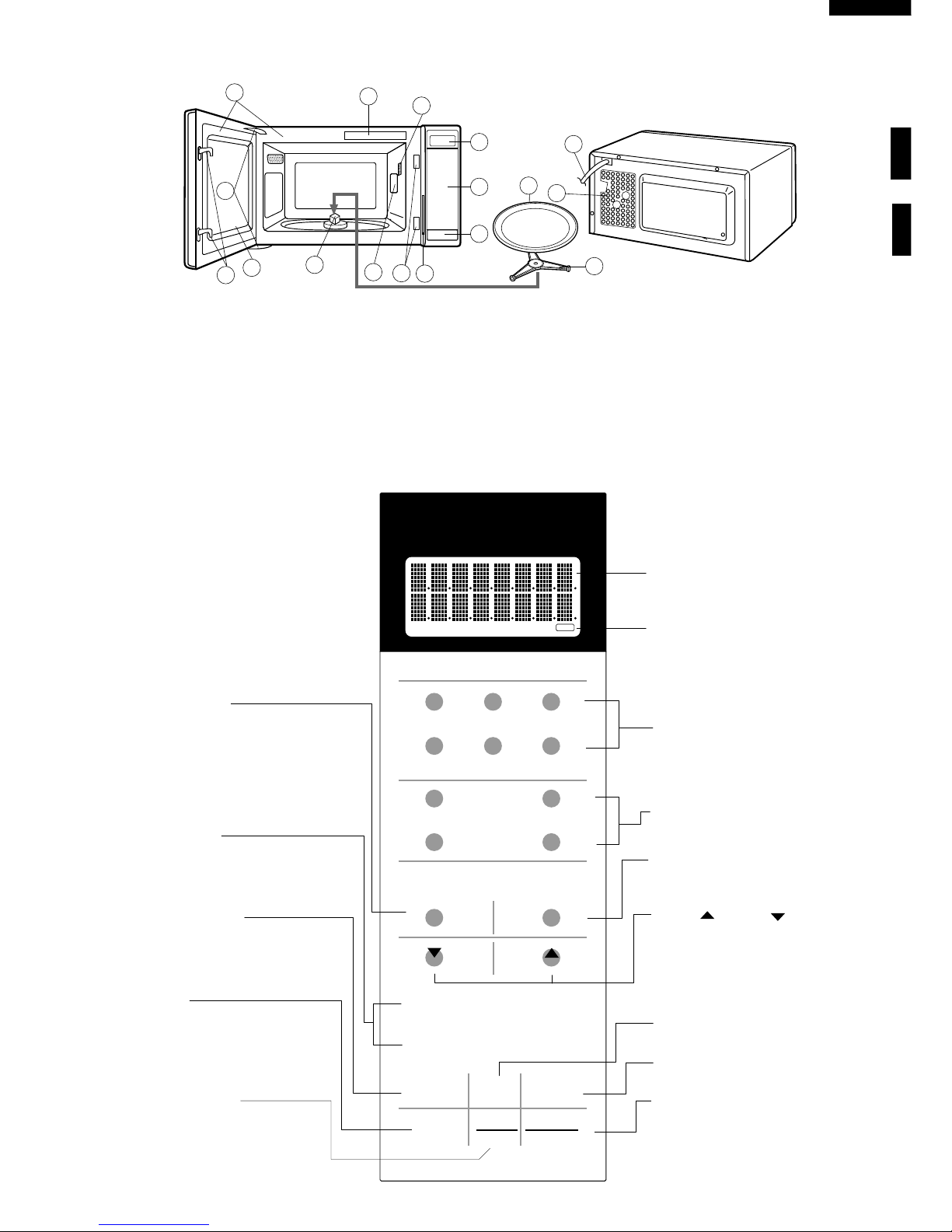
APPEARANCE VIEW
1. Ventilation openings
2. Oven lamp
3. Door hinges
4. Door safety latches
5. See through door
10
3
4
2
7
13
5
6
14
4
11
8
16
9
12
15
1
SENSOR DEFROST COOK
HELP
Info Display
Sensor Instant Reheat
Sensor Cook
DINNER
PLATE
CASSEROLE
SOUP
PIZZA RICE PIE
VEGETABLES RICE/PASTA
DESSERTS
MEAT
LESS
POWER
LEVEL
STOP
CLEAR
CLOCK TIMER
HELP
MORE
SLOW
COOK
EASY
DEFROST
1234 5
6789 0
INSTANT COOK
START
STOP/CLEAR PAD
Press to clear during programming.
Press once to stop operation of
oven during cooking; press twice to
cancel cooking programme.
POWER LEVEL PAD
Press to select microwave power
setting. If not pressed, HIGH is automatically selected.
INSTANT COOK/START PAD
Press once to cook for 1 minute on
HIGH or increase in 1 minute increments each time this pad is pressed
during cooking. Press to start the oven
after setting programmes.
HELP PAD
Press to select auto start, information
guide on/off, child lock, demonstration modes or info on pads.
Press to get cooking information.
SENSOR COOK PADS
Press to select Sensor Cook menus.
SENSOR INSTANT REHEAT PADS
Press once to reheat 1 of 6 popular
menus.
EASY DEFROST PAD
Press to defrost frozen food by entering quantity.
MORE( ), LESS ( ) PADS
Press to increase/ decrease the time
in one minute increments during
cooking or alter the cooking result for
Sensor Instant Reheat, Sensor Cook
or Easy Defrost modes.
NUMBER PADS
Press to enter cooking times, clock time,
weight or quantity of food.
TIMER PAD
Press to set Timer
CLOCK PAD
Press to set Clock.
SLOW COOK PAD
Press to cook slowly and for a long
time.
Indicator
Display
6. Door seals and sealing surfaces
7. Coupling
8. Door open button
9. Touch control panel
10.Digital readout
11.Waveguide cover
12.Power supply cord
13.Rating label
14.Menu label
15.Turntable
16.Roller stay
TOUCH CONTROL PANEL
Page 6

4
R-490C(S)
CONTROL PANEL ASSEMBLY REMOVAL
1. CARRY OUT 3D CHECKS.
2. Disconnect wire leads from panel components.
3. Release one (1) nail holding the control panel assembly
to the oven flange.
4. Remove control panel assembly and slide upward.
5. Now, the control panel assembly is free.
NOTE: The key unit can not be exchanged by itself.
Because the control panel decoration is fixed by
the both sides adhesive tape. The Control panel
frame with key unit should be available as spare
part.
CPU UNIT AND POWER UNIT
NOTE: Handle the CPU unit carefully so that the ribbon
cable does not come off. Because the ribbon cable
is sticked on the LCD and the printed wiring board
only by heated paste.
Figure C-3. CPU unit
Printed wiring board
of CPU unit
Liquid Crystal
Display (LCD)
Ribbon cable
COMPONENT REPLACEMENT AND ADJUSTMENT PROCEDURE
WARNING:
Avoid possible exposure to microwave energy. Please follow the instructions below before
operating the oven.
1. Disconnect the oven from the power supply.
2. Make sure that a definite “click” can be heard when the
microwave oven door is unlatched. (Hold the door in a
closed position with one hand, then push the door open
button with the other, this causes the latch leads to rise,
it is then possible to hear a “click” as the door switches
operate.)
3. Visually check the door and cavity face plate for damage
(dents, cracks, signs of arcing etc.).
Carry out any remedial work that is necessary before
operating the oven.
Do not operate the oven if any of the following conditions
exist;
1. Door does not close firmly.
2. Door hinge, support or latch hook is damaged.
3. The door gasket or seal or damaged.
4. The door is bent or warped.
5. There are defective parts in the door interlock system.
6. There are defective parts in the microwave generating
and transmission assembly.
7. There is visible damage to the oven.
Do not operate the oven:
1. Without the RF gasket (Magnetron).
2. If the wave guide or oven cavity are not intact.
3. If the door is not closed.
4. If the outer case (cabinet) is not fitted.
Please refer to ‘OVEN PARTS, CABINET PARTS, CONTROL PANEL PARTS, DOOR PARTS’, when carrying out any
of the following removal procedures:
WARNING FOR WIRING
To prevent an electric shock, take the following
manners.
1. Before wiring,
1) Disconnect the power supply.
2) Open the door and wedge the door open.
3) Discharge the high voltage capacitor and wait for
60 seconds.
2. Don't let the wire leads touch to the following parts;
1) High voltage parts:
Magnetron, High voltage transformer, High
voltage capacitor, High voltage rectifier assembly
and High voltage fuse.
2) Hot parts:
Oven lamp, Magnetron, High voltage transformer
and Oven cavity.
3) Sharp edge:
Bottom plate, Oven cavity, Waveguide flange,
Chassis support and other metallic plate.
4) Movable parts (to prevent a fault)
Fan blade, Fan motor, Switch, Switch lever,
Open button.
3. Do not catch the wire leads in the outer case cabinet.
4. Insert the positive lock connector certainly until its
pin is locked. And make sure that the wire leads
should not come off even if the wire leads is pulled.
5. To prevent an error function, connect the wire leads
correctly, referring to the Pictorial Diagram.
Page 7

R-490C(S)
5
DOOR REPLACEMENT
REMOVAL
1. Disconnect the power supply cord.
2. Push the open button and open the door slightly.
3. Insert a putty knife (thickness of about 0.5mm) into the
gap between the choke cover and door frame as shown
in Figure C-6 to free engaging parts.
4. Pry the choke cover by inserting a putty knife as shown
Figure C-6.
5. Release choke cover from door panel.
6. Now choke cover is free.
7. Release two (2) pins of door panel from two (2) holes
of upper and lower oven hinges by lifting up.
8. Now, door panel with door frame is free from oven
cavity.
Figure C-6. Door Disassembly
9. Remove the two (2) screws holding the door panel to
the door frame.
10.Release door panel from nine (9) tabs of door frame.
11.Now, door panel with sealer film is free.
12.Tear sealer film from door panel.
13.Now, door panel is free.
14.Slide latch head upward and remove it from door frame
with releasing latch spring from door frame and latch
head.
15.Now, latch head and latch spring are free.
16.Now, the door frame assembly is free.
NOTE: The door glass can not be exchanged by itself.
Because the door decoration is fixed by the both
sides adhesive tape. The Door frame assembly
should be available as spare part.
RE-INSTALL
1. Re-install the latch spring to the latch head. Re-install
the latch spring to the door frame. Re-install latch head
to door frame.
2. Re-install door panel to door frame by fitting nine (9)
tabs of door frame to nine (9) holes of door panel.
3. Hold the door panel to the door frame with the two (2)
screws.
4. Put sealer film on door panel. Refer to “Sealer Film”
about how to handle new one.
5. Catch two (2) pins of door panel on two (2) hole of upper
and lower oven hinges.
6. Re-install choke cover to door panel by pushing.
Note: After any service to the door;
(A) Make sure that 1st. latch switch, 2nd. latch switch,
stop switch and monitor switch are operating
properly. (Refer to chapter “Test Procedures”.).
(B) An approved microwave survey meter should be
used to assure compliance with proper microwave
radiation emission limitation standards.
After any service, make sure of the following :
1. Door latch heads smoothly catch latch hook through
latch holes and that latch head goes through center of
latch hole.
2. Deviation of door alignment from horizontal line of
cavity face plate is to be less than 1.0mm.
3. Door is positioned with its face pressed toward cavity
face plate.
4. Check for microwave leakage around door with an
approved microwave survey meter. (Refer to Microwave
Measurement Procedure.)
Note: The door on a microwave oven is designed to act
as an electronic seal preventing the leakage of
microwave energy from oven cavity during cook
cycle. This function does not require that door be
air-tight, moisture (condensation)-tight or lighttight. Therefore, occasional appearance of
moisture, light or sensing of gentle warm air
movement around oven door is not abnormal and
do not of themselves indicate a leakage of
microwave energy from oven cavity.
Figure C-7. Door Replacement
SEALER FILM
Installation
1. Put the adhesive tape on the backing film of the sealer
film as shown in Fig. C-8.
2. Tear the backing film by pulling the adhesive tape.
3. Put the pasted side of the sealer film on the door panel
Figure C-8. Sealer film
Sealer film
Backing film
Adhesive tape
Choke Cover
Door Frame
Putty Knife
Pin
Pin
Upper
Oven Hinge
Upper Oven
Hinge
Lower Oven
Hinge
Lower
Oven Hinge
Choke Cover
Door Panel
Page 8

6
R-490C(S)
mW cm
2
mW cm
2
Microwave leakage measurement at 5 cm distance
SHARP
MICROWAVE MEASUREMENT
After adjustment of door latch switches, monitor switch
and door are completed individually or collectively, the
following leakage test must be performed with a survey
instrument and it must be confirmed that the result meets
the requirements of the performance standard for microwave oven.
REQUIREMENT
The safety switch must prevent microwave radiation emission in excess of 5mW/cm2 at any point 5cm or more from
external surface of the oven.
PREPARATION FOR TESTING:
Before beginning the actual test for leakage, proceed as
follows;
1. Make sure that the test instrument is operating normally
as specified in its instruction booklet.
Important:
Survey instruments that comply with the requirement
for instrumentations as prescribed by the performance
standard for microwave ovens must be used for testing.
Recommended instruments are:
NARDA 8100
NARDA 8200
HOLADAY HI 1500
SIMPSON 380M
2. Place the oven tray into the oven cavity.
3. Place the load of 275 ± 15ml of water initially at 20
± 5˚C in the centre of the oven tray. The water
container should be a low form of 600 ml beaker with
inside diameter of approx. 8.5cm and made of an
electrically non-conductive material such as glass
or plastic.
The placing of this standard load in the oven is important
not only to protect the oven, but also to insure that any
leakage is measured accurately.
4. Close the door and turn the oven ON with the timer set
for several minutes. If the water begins to boil before
the survey is completed, replace it with 275ml of cool
water.
5. Move the probe slowly (not faster that 2.5cm/sec.)
along the gap.
6. The microwave radiation emission should be measured
at any point of 5cm or more from the external surface
of the oven.
Page 9

R-490C(S)
7
SCHEMATIC
NOTE: CONDITION OF OVEN
1.DOOR CLOSED.
2.CLOCK APPEARS ON DISPLAY.
NOTE: " " indicates components with potentials above 250V.
Figure O-1. Oven Schematic-OFF Condition
SCHEMATIC
NOTE: CONDITION OF OVEN
1. DOOR CLOSED.
2. COOKING TIME PROGRAMMED.
3. START KEY TOUCHED.
Figure O-2. Oven Schematic-Cooking Condition
POWER TRANSFORMER
MAGNETRON
H.V. RECTIFIER
H. V. FUSE
0.75A
CAPACITOR
1.13µ
AC2300V
TURNTABLE MOTOR
FAN MOTOR
OVEN LAMP
STOP
SWITCH
MONITOR SWITCH
CONTROL
UNIT
MAGNETRON
TEMPERATURE
FUSE
1ST. LATCH
SWITCH
B1
B2
A2
OL
FM
TTM
N.O.
N.O.
RY-1
COM.
COM.
A1
THERMAL
CUT-OUT
145˚C (OVEN)
RY-2
2ND. LATCH
SWITCH
MONITOR
RESISTOR
0.8/20W
EARTH
BLU
BRN
230-240V/50Hz
G-Y
FUSE
M10A
N
L
LINE CROSS CAPACITOR
0.068µ/AC250V
NOISE SUPPRESSION COIL
LINE BYPASS
CAPACITOR
0.0022µ/AC250V
LINE BYPASS
CAPACITOR
0.0022µ/AC250V
F1
F2
F3
AH
SENSOR
Page 10

8
R-490C(S)
6
45
1
2
3
6
45
1
2
3
A
B
C
D
E
F
G
H
A
B
C
D
E
F
G
H
Figure S-1. Pictorial Diagram
COM.
MONITOR
SWITCH
COM.
N.O.
N.C.
1ST.
LATCH
SWITCH
2ND.
LATCH
SWITCH
STOP
SWITCH
(CABINET SIDE)
(OVEN SIDE)
TURNTABLE
MOTOR
COM.
N.O.
BLK
GRY
GRY
WHT
GRN
WHT
WHT
BLU
BLK
WHT
WHT
WHT
RED
WHT
WHT
THERMAL
CUT-OUT (OVEN)
NOISE FILTER
GRN
GRY
COM.
N.O.
BLK
RED
GRN
ORG
BLK
ORG
RED
RED
GRY
2
1
CN-A
GRN
GRY
2
1
CN-B
BLU
BRN
POWER
SUPPLY
CORD
EARTH
NEUTRAL
LIVE
G
/
Y
N
L
WHT
RED
M10A
CONTROL PANEL
RY1
N.O.
N.O.
COM.
COM.
RY2
CN-A
CN-B
T1
112
2
(CPU UNIT)
(POWER UNIT)
CN-F
CN-C
CN-G
RED
ORG
ORG
W
H
T
OVEN LAMP
AND SOCKET
BLACK
MARK
NOTE:
Neutral (WHT) wire
must be connected
to the terminal with
black mark on the
oven light socket.
ORGWHT
ORG
RED
MAGNETRON
TEMPERATURE
FUSE
(OVEN SIDE)
BLK
ORG
MONITOR
RESISTOR
H.V.RECTIFIER
H.V. FUSE
HIGH VOLTAGE
CAPACITOR
HIGH VOLTAGE COMPONENTS
MAGNETRON
POWER
TRANSFORMER
ORG
BLK
BLU
GRY
BLK
AH SENSOR
RED
WHT
123
CN-F
Page 11

R-490C(S)
9
PARTS LIST
Note: The parts marked "∆" may cause undue microwave exposure.
The parts marked "*" are used in voltage more than 250V.
REF. NO. PART NO. DESCRIPTION Q'TY CODE
*
*
*
*
∆*
*
ELECTRICAL PARTS
1- 1 QFS-TA014WRE0 Temp. fuse 150˚C (MG) 1 AG
1- 2 FPWBFA331WRK0 Noise filter 1 AU
1- 3 QSW-MA131WRE0 1st. latch switch, 2nd. latch switch, Stop switch 3 AG
1- 4 QSW-MA132WRE0 Monitor switch 1 AH
1- 5 RTHM-A075WRE0 Thermal cut-out 145˚C (OVEN) 1 AN
1- 6 QACCAA047WRE0 Power supply cord 1 AP
1- 7 FH-DZA069WRK0 H.V. rectifier assembly 1 AP
1- 7 FH-DZA067WRK0 H.V. rectifier assembly (Interchangeable) 1 AQ
1- 8 RC-QZA258WRE0 High Voltage capacitor 1 AW
1- 9 RMOTEA328WRE0 Fan motor 1 AX
1- 9 RMOTEA342WRE0 Fan motor (Interchangeable) 1 AX
1-10 QFS-CQ001YBE0 Fuse M10A 1 AE
1-11 QSOCLA022WRE0 Oven lamp socket 1 AG
1-12 RLMPTA069WRE0 Oven lamp 1 AK
1-12 RLMPTA029WRE0 Oven lamp (Interchangeable) 1 AL
1-13 RMOTDA173WRE0 Turntable motor 1 AX
1-13 RMOTDA226WRE0 Turntable motor (Interchangeable) 1 AT
1-14 RTRN-A585WRE0 Power transformer 1 BQ
1-15 RV-MZA295WRE0 Magnetron 1 BF
1-16 RR-WZA022WRE0 Monitor resistor 0.8 ohm 20W 1 AK
1-17 FDTCTA179WRK0 AH sensor assembly 1 BA
1-18 QFS-IA002WRE0 H.V. fuse 1 AQ
CABINET PARTS
2- 1 GCABUA732WRP0 Outer case cabinet 1 BF
2- 2 GDAI-A266WRW0 Bottom plate 1 AL
2- 3 GLEGPA074WRE0 Foot 4 AC
CONTROL PANEL PARTS
3- 1 CPWBFA835WRK0 Power unit (New Zealand only) 1 BB
3- 1A QCNCMA446DRE0 2-pin connector(CN-A) 1 AC
3- 1B QCNCMA275DRE0 2-pin connector(CN-B) 1 AB
3- 1C FW-VZA232DRE0 12-pin harness (CN-C) 1 AE
C1 RC-KZA087DRE0 Capacitor 0.1µF 50V 1 AA
C2 VCEAB31VW108M Capacitor 1000µF 35V 1 AF
C3 RC-KZA087DRE0 Capacitor 0.1µF 50V 1 AA
C4-5 VCEAB31VW106M Capacitor 10µF 35V 2 AA
D1-4 VHD11ES1///-1 Diode (11ES1) 4 AB
D5-8 VHD1SS270A/-1 Diode (1SS270ATA) 4 AA
Q1-2 VS2SB1238//-3 Transistor (2SB1238) 2 AA
Q3 VSKRC243M//-3 Transistor (KRC243M) 1 AB
R1 VRD-B12EF242J Resistor 2.4k ohm 1/4W 1 AA
R2 VRS-B12HF681J Resistor 680 ohm 1/2W 1 AA
R3 VRD-B12HF511J Resistor 510 ohm 1/2W 1 AB
R4 VRD-B12EF270J Resistor 27 ohm 1/4W 1 AB
R5 VRD-B12EF472J Resistor 4.7k ohm 1/4W 1 AA
R6 VRD-B12EF332J Resistor 3.3k ohm 1/4W 1 AA
RY1 RRLY-A076DRE0 Relay (OMIF-S-124LM) 1 AK
RY2 RRLY-A081DRE0 Relay (VRB24) 1 AL
SP1 RALM-A014DRE0 Buzzer (PKM22EPT-THAI) 1 AG
T1 RTRNPA112DRE0 Transformer 1 AS
VRS1 RH-VZA032DRE0 Varistor (10G471K) 1 AE
ZD1 VHEHZ161///-1 Zenor diode (HZ16-1) 1 AA
3- 2 DPWBFB965WRK0 CPU unit 1 BH
3- 3 FPNLCB467WRK0 Control panel frame with key unit 1 BP
3- 3-1 HDECAA205WR10 C/P decoration 1 BF
3- 3-2 JBTN-B091MRF0 Open button 1 AN
3- 3-3 MSPRCA050WRE0 Open button spring 1 AB
3- 4 LHLD-B010MRF0 LCD holder 1 AQ
3- 5 PSHEPA672WRE0 LED sheet 1 AK
3- 6 XEPSD30P08XS0 Screw ; 3mm x 8mm 4 AA
OVEN PARTS
4- 1 PHOK-A095WRF0 Latch hook 1 AN
4- 2 LBNDKA132WRP0 Capacitor holder 1 AD
4- 3 PCOVPA312WRE0 High voltage cover 1 AF
4- 4 NFANJA020WRE0 Fan blade 1 AG
4- 5 FOVN-A387WRT0 Oven cavity 1 BL
∆
∆
Page 12

10
R-490C(S)
HOW TO ORDER REPLACEMENT PARTS
To have your order filled prompty and correctly, please furnish the following information.
1. MODEL NUMBER
2. REF. NO.
3. PART NO.
4. DESCRIPTION
Note: The parts marked "∆" may cause undue microwave exposure.
The parts marked "*" are used in voltage more than 250V.
REF. NO. PART NO. DESCRIPTION Q'TY CODE
∆
∆
∆
4- 6 LANGTA316WRP0 Chassis support 1 AH
4- 7 MLEVPA194WRF0 Switch lever 1 AG
4- 8 NCPL-A052WRF0 Turntable coupling 1 AF
4- 9 PCOVPA311WRE0 Waveguide cover 1 AG
4-10 PCUSUA191WRP0 Cushion 1 AC
4-11 PDUC-A610WRF0 Fan duct 1 AR
4-12 PDUC-A611WRW0 Magnetron air duct 1 AC
4-13 PPACGA119WRE0 Waterproof packing 1 AC
4-14 PCUSUA410WRP0 Cushion 1 AB
4-15 PCUSUA455WRP0 Cushion 1 AD
4-16 PPACGA073WRE0 Cushion 1 AP
4-17 PCUSUA452WRP0 Cushion 1 AB
4-18 PCUSGA531WRP0 Cushion 1 AF
4-19 PCUSUA237WRP0 Cushion 1 AF
4-20 PSKR-A319WRF0 MG air guide 1 AE
4-21 PSKR-A321WRP0 Air guide 1 AY
4-22 PCUSGA532WRP0 Cushion 1 AF
4-23 PDUC-A661WRP0 AH sensor duct 1 BC
4-24 PCUSGA534WRP0 Cushion 1 AF
DOOR PARTS
5- 1 FDORFA290WRT0 Door panel 1 BA
5- 2 FWAKPA234WRK0 Door frame assembly 1 BQ
5-2-1 HDECAB081MRP0 Door decoration 1 AX
5- 3 LSTPPA139WRF0 Latch head 1 AF
5- 4 MSPRTA084WRE0 Latch spring 1 AD
5- 5 XEPSD30P08XS0 Screw; M3 x 8 2 AA
5- 6 GCOVHA414WR10 Choke cover 1 AM
5- 7 PSHEPA336WRP0 Sealer film 1 AF
MISCELLANEOUS
6- 1 TSPCNC816WRR0 Rating label 1 AC
6- 2 FW-VZB122WRE0 Switch harness 1 AP
6- 3 FW-VZB745WRE0 Main wire harness 1 AU
6- 4 FROLPA092WRK0 Turntable support 1 AE
6- 5 TLABMA539WRR0 Menu label 1 AF
6- 6 PZET-A012WRE0 Terminal insulator 1 AB
6- 7 TCAUHA214WRR0 K caution label 1 AC
6- 8 TINSEA817WRR0 Operation manual 1 AR
6- 9 NTNT-A095WRE0 Turntable tray 1 AX
SCREWS, NUTS AND WASHERS
7- 1 XHTSD40P08RV0 Screw; M4 x 8 11 AA
7- 2 LX-CZ0052WRE0 Special screw 2 AA
7- 3 LX-EZA042WRE0 Special screw 2 AB
7- 4 XHPSD30P06000 Screw; M3 x 6 3 AA
7- 5 XHPSD40P08K00 Screw; M4 x 8 9 AA
7- 6 XHPSD30P08XS0 Screw; M3 x 8 1 AA
7- 7 LX-EZA050WRE0 Special screw; 1 AB
7- 8 XOTSD40P12RV0 Screw; M4 x 12 12 AB
7- 9 XOTSD40P12000 Screw; M4 x 12 2 AA
Page 13

R-490C(S)
11
6
45
1
2
3
6
45
1
2
3
A
B
C
D
E
F
G
H
A
B
C
D
E
F
G
H
OVEN AND CABINET PARTS
7-8
7-8
7-8
7-8
2-1
6-9
1-5
4-5
4-23
7-1
4-11
7-1
7-4
7-1
4-6
7-5
1-15
7-1
4-21
7-2
4-9
1-13
7-5
4-1
4-7
1-9
4-4
1-3
1-4
1-3
1-14
1-1
1-11
1-12
7-9
2-3
7-8
2-2
4-15
7-8
2-3
2-3
6-4
6-5
4-8
4-19
7-1
1-7
1-8
7-1
4-16
4-2
4-17
A
A
4-3
1-18
7-5
4-24
4-12
4-18
4-20
4-10
6-7
1-3
1-6
7-7
7-5
1-10
1-2
7-5
7-8
7-1
7-8
7-8
7-1
1-16
4-14
4-13
7-1
7-6
7-3
7-1
7-4
1-17
4-22
Page 14

12
R-490C(S)
6
45
1
2
3
6
45
1
2
3
A
B
C
D
E
F
G
H
A
B
C
D
E
F
G
H
CONTROL PANEL PARTS
MISCELLANEOUS
6-2
6-6
Actual wire harness may be different from illustration.
6-3
5-6
5-5
5-5
5-7
5-3
5-1
5-4
5-2-1
5-2
3-1
3-6
3-6
3-6
3-6
3-2
3-3
6-1
3-4
3-5
3-3-3
3-3-2
3-3-1
DOOR PARTS
Page 15

R-490C(S)
13
6
45
1
2
3
6
45
1
2
3
A
B
C
D
E
F
G
H
A
B
C
D
E
F
G
H
PACKING AND ACCESSORIES
DOOR PROTECTION SHEET
SPADPA204WRE0
TOP PAD ASSEMBLY
FPADBA317WRK0
PLASTIC BAG
SSAKHA032WRE0
Not replaceable items.
PACKING CASE
SPAKCD305WRE0
BOTTOM PAD ASSEMBLY
FPADBA318WRK0
6-9 TURNTABLE TRAY
6- 8 OPERATION MANUAL
6-4 TURNTABLE SUPPORT
TRAY PACK
SPADFA389WRE0
INTO THE
OVEN CAVITY
Page 16

14
R-490C(S)
'99SHARP CORP. (09S0.720E) Printed in Australia
 Loading...