


TopPage
R395N(S)
SERVICE MANUAL
S2901R395NPJS
MICROWAVE OVEN
MODEL
In the interests of user-safety the oven should be restored to its original condition and only parts identical to those
specified should be used.
R-395N(S)
CONTENTS
CHAPTER 1. BEFORE SERVICING
CHAPTER 2. WARNING TO SERVICE PERSONNEL
CHAPTER 3. PRODUCT SPECIFICATIONS
CHAPTER 4. APPEARANCE VIEW
CHAPTER 5. OPERATION SEQUENCE
CHAPTER 6. FUNCTION OF IMPORTANT COMPONENTS
CHAPTER 7. TROUBLESHOOTING GUIDE
CHAPTER 9. TOUCH CONTROL PANEL ASSEMBLY
CHAPTER 10. PRECAUTIONS FOR USING LEADFREE SOLDER
CHAPTER 11. COMPONENT REPLACEMENT AND
ADJUSTMENT PROCEDURE
CHAPTER 12. MICROWAVE MEASUREMENT
CHAPTER 13. CIRCUIT DIAGRAMS
Parts List
CHAPTER 8. TEST PROCEDURES
This document has been published to be used for
after sales service only.
The contents are subject to change without notice.

CONTENTS
CHAPTER 1. BEFORE SERVICING
[1] GENERAL IMPORTANT INFORMA-
TION ........................................................... 1-1
[2] CAUTION MICROWAVE RADIATION ........ 1-1
[3] WARNING................................................... 1-1
CHAPTER 2. WARNING TO SERVICE PERSONNEL
CHAPTER 3. PRODUCT SPECIFICATIONS
CHAPTER 4. APPEARANCE VIEW
[1] OVEN.......................................................... 4-1
[2] TOUCH CONTROL PANEL ........................ 4-1
CHAPTER 5. OPERATION SEQUENCE
[1] OFF CONDITION........................................ 5-1
[2] MICROWAVE COOKING CONDITION....... 5-1
[3] POWER OUTPUT REDUCTION ................ 5-1
CHAPTER 6. FUNCTION OF IMPORTANT COMPONENTS
[1] DOOR OPEN MECHANISM ....................... 6-1
[2] 1ST. LATCH SWITCH AND 2ND. IN-
TERLOCK RELAY CONTROL SWITCH..... 6-1
[3] MONITOR SWITCH ................................... 6-1
[4] FUSE F10A................................................. 6-1
[5] HIGH VOLTAGE FUSE .............................. 6-1
[6] OVEN TEMPERATURE FUSE ................... 6-1
[7] TURNTABLE MOTOR................................. 6-1
[8] FAN MOTOR............................................... 6-1
[9] NOISE FILTER............................................ 6-1
CHAPTER 7. TROUBLESHOOTING GUIDE
[1] FOREWORD............................................... 7-1
[2] CHART........................................................ 7-1
CHAPTER 8. TEST PROCEDURES
[1] A: MAGNETRON (MG) TEST..................... 8-1
[2] B: POWER TRANSFORMER TEST ........... 8-2
[3] C: HIGH VOLTAGE RECTIFIER TEST....... 8-2
[4] D: HIGH VOLTAGE CAPACITOR TEST..... 8-2
[5] E: SWITCH TEST ....................................... 8-3
[6] F: TEMPERATURE FUSE TEST ................ 8-3
[7] G: MOTOR WINDING TEST....................... 8-3
[8] H: FUSE F10A ............................................ 8-3
[9] I: NOISE FILTER TEST .............................. 8-4
[10] J: HIGH VOLTAGE FUSE TEST ................. 8-4
[11] K: TOUCH CONTROL PANEL ASSEM-
BLY TEST ................................................... 8-4
[12] L: KEY UNIT (MEMBRANE SWITCH)
TEST........................................................... 8-5
[13] M: RELAY TEST ......................................... 8-5
[14] N: PROCEDURES TO BE TAKEN
WHEN THE FOIL PATTERN ON THE
PRINTED WIRING BOARD (PWB) IS
OPEN.......................................................... 8-5
CHAPTER 9. TOUCH CONTROL PANEL ASSEMBLY
[1] OUTLINE OF TOUCH CONTROL PAN-
EL ............................................................... 9-1
[2] SERVICING FOR TOUCH CONTROL
PANEL ........................................................ 9-1
CHAPTER 10. PRECAUTIONS FOR USING LEADFREE SOLDER
CHAPTER 11. COMPONENT REPLACEMENT
AND ADJUSTMENT PROCEDURE
[1] BEFORE OPERATING ..............................11-1
[2] OUTER CASE REMOVAL .........................11-1
[3] POWER TRANSFORMER REMOVAL ......11-2
[4] HIGH VOLTAGE RECTIFIER ASSEM-
BLY, HIGH VOLTAGE FUSE AND HIGH
VOLTAGE CAPACITOR REMOVAL...........11-2
[5] MAGNETRON REMOVAL .........................11-2
[6] POSITIVE LOCK CONNECTOR (NO-
CASE TYPE) REMOVAL ...........................11-2
[7] CONTROL PANEL ASSEMBLY RE-
MOVAL.......................................................11-3
[8] GRAPHIC SHEET AND MEMBRANE
SWITCH REPLACEMENT .........................11-3
[9] TURNTABLE MOTOR REMOVAL .............11-3
[10] COOLING FAN MOTOR REMOVAL..........11-3
[11] POWER SUPPLY CORD REPLACE-
MENT.........................................................11-4
[12] 1ST. LATCH SWITCH, 2ND. INTER-
LOCK RELAY CONTROL SWITCH AND
MONITOR SWITCH REMOVAL.................11-4
[13] 1ST. LATCH SWITCH, 2ND. INTER-
LOCK RELAY CONTROL SWITCH AND
MONITOR SWITCH ADJUSTMENT..........11-5
[14] DOOR REPLACEMENT ............................11-5
CHAPTER 12. MICROWAVE MEASUREMENT
CHAPTER 13. CIRCUIT DIAGRAMS
[1] Oven Schematic........................................ 13-1
[2] Pictorial Diagram (Figure S-1) .................. 13-2
[3] Control Unit Circuit (Figure S-2)................ 13-3
[4] Printed Wiring Board (Figure S-3)............. 13-4
Parts List

R395N(S)
1 – 1
R395N(S)
ServiceManual
CHAPTER 1. BEFORE SERVICING
[1] GENERAL IMPORTANT INFORMATION
This Manual has been prepared to provide Sharp Corp. Service engineers with Operation and Service Information.
It is recommended that service engineers carefully study the entire text of this manual, so they will be qualified to render satisfactory customer service.
[2] CAUTION MICROWAVE RADIATION
DO NOT BECOME EXPOSED TO RADIATION FROM THE MICROWAVE GENERATOR OR OTHER PARTS CONDUCTING MICROWAVE ENERGY.
Service engineers should not be exposed to the microwave energy which may radiate from the magnetron or other
microwave generating devices if it is improperly used or connected. All input and output microwave connections,
waveguides, flanges and gaskets must be secured. Never operate the device without a microwave energy absorbing
load attached. Never look into an open waveguide or antenna while the device is energized.
[3] WARNING
Never operate the oven until the following points are ensured.
(A) The door is tightly closed.
(B) The door brackets and hinges are not defective.
(C) The door packing is not damaged.
(D) The door is not deformed or warped.
(E) There is not any other visible damage with the oven.
Servicing and repair work must be carried out only by trained service engineers.
All the parts marked " " on parts list are used at voltages more than 250V.
Removal of the outer wrap gives access to potentials above 250V.
All the parts marked "*" on parts list may cause undue microwave exposure, by themselves, or when they are damaged,
loosened or removed.
WARNING: THIS APPLIANCE MUST BE EARTHED
IMPORTANT
THE WIRES IN THIS MAINS LEAD ARE COLOURED IN ACCORDANCE WITH THE FOLLOWING CODE:
GREEN-AND-YELLOW --------------EARTH
BLUE -----------------------------------NEUTRAL
BROWN ---------------------------------------LIVE

R395N(S)
2 – 1
R395N(S)
ServiceManual
CHAPTER 2. WARNING TO SERVICE PERSONNEL
Microwave ovens contain circuitry capable of producing very high voltage and current, contact with any part of the high voltage circuit will result in
electrocution. High voltage capacitor, Power transformer, Magnetron, High voltage rectifier assembly, High voltage harness and High voltage fuse.
REMEMBER TO CHECK 3D
1) Disconnect the supply.
2) Door opened, and wedged open.
3) Discharge the high voltage capacitor.
WARNING: AGAINST THE CHARGE OF THE HIGH-VOLTAGE
CAPACITOR
The high-voltage capacitor remains charged about 60 seconds after the oven has been switched off. Wait for 60 seconds and then short-circuit the connection of the highvoltage capacitor (that is, of the connecting lead of the
high-voltage rectifier) against the chassis with the use of
an insulated screwdriver.
Sharp recommend that wherever possible fault-finding is carried out
with the supply disconnected. It may, in some cases, be necessary to
connect the supply after the outer case has been removed, in this
event carry out 3D
checks and then disconnect the leads to the primary of the power transformer. Ensure that these leads remain isolated from other components and the oven chassis. (Use insulation
tape if necessary.) When the testing is completed, carry out 3D
checks
and reconnect the leads to the primary of the power transformer.
REMEMBER TO CHECK 4R
1) Reconnect all leads removed from components during testing.
2) Replace the outer case (cabinet).
3) Reconnect the supply.
4) Run the oven. Check all functions.
Microwave ovens should not be run empty. To test for the presence of
microwave energy within a cavity, place a cup of cold water on the
oven turntable, close the door and set the microwave timer for two (2)
minutes. Set the power level to HIGH and push the START button.
When the two minutes has elapsed (timer at zero) carefully check that
the water is now hot. If the water remains cold carry out 3D
checks and
reexamine the connections to the component being tested.
When all service work is completed and the oven is fully assembled, the microwave power output should be checked and microwave leakage test
should be carried out.

R395N(S)
3 – 1
R395N(S)
ServiceManual
CHAPTER 3. PRODUCT SPECIFICATIONS
ITEM DESCRIPTION
Power Requirements
230 - 240 Volts
50 Hertz
Single phase, 3 wire earthed
Power Consumption 1.6 k W
Power Output
1100 watts nominal of RF microwave energy (IEC Test Procedure)
Operating frequency 2450 MHz
Case Dimensions
Width 520 mm
Height 310 mmincluding foot
Depth 442 mm
Turntable Diameter 320 mm
Control Complement
Touch Control System
Clock (1:00 - 12:59)
Timer (0 - 99 minutes 99 seconds)
Microwave Power for Variable Cooking
Repetition Rate;
100P ..................................................................... Full power throughout the cooking time
70P ....................................................................... approx. 70% of FULL Power
50P ....................................................................... approx. 50% of FULL Power
30P ...................................................................... approx. 30% of FULL Power
10P ....................................................................... approx. 10% of FULL Power
INSTANT ACTION pads
EXPRESS DEFROST pad
EASY DEFROST pad
NUMBER pads
POWER LEVEL pad
TIMER/CLOCK pad
STOP/CLEAR pad
INSTANT COOK/START pad
Set Weight (Approx.) 17 kg

R395N(S)
4 – 1
R395N(S)
ServiceManual
CHAPTER 4. APPEARANCE VIEW
[1] OVEN
1. Door open button
2. Oven lamp
3. Door hinges
4. Door safety latches
5. See through door
6. Door seal and sealing surfaces
7. Coupling
8. Wave guide cover
9. Touch control panel
10.Liquid crystal display
11.Ventilation openings 12. Power supply cord 13. Turntable 14. Roller stay 15. Menu label
[2] TOUCH CONTROL PANEL
NOTE: Some one-touch cooking features such as “INSTANT COOK” are disabled after one minute when the oven is not in use. These fea-
tures are automatically enabled when the door is opened and closed or the STOP/CLEAR pad is pressed.
6
2
84
4
5
3
1
9
10
15
7
13
14
11
12
Indicators
EASY DEFROST PAD
Press to selec tthe Easy Defrost menu.
NUMBER PADS
Press to enter cooking time, clock time,
weight of food.
TIMER/CLOCK PAD
Press to set clock, timer, child lock or
demonstration mode.
INST ANTCOOK/STARTPAD
Press to start oven after setting programmes.
Press once to cook for 1 minute at
HIGH or increase by 1 minute multiples each time this pad is pressed
during cooking.
INSTANT ACTION PADS
Press to cook or reheat 8 popular
menus.
EXPRESS DEFROST PAD
Press to select the Express Defrost
menu.
POWER LEVEL PAD
Press to select microwave power
setting.If not pressed, HIGH is automatically selected.
Press to alter the cooking result for
automaticoperations.
STOP/CLEAR PAD
Press to clear during programming.
Press once to stop operation of
oven during cooking; press twice to
cancel cooking programme.

R395N(S)
5 – 1
R395N(S)
ServiceManual
CHAPTER 5. OPERATION SEQUENCE
[1] OFF CONDITION
Closing the door activates all door interlock switches (1st. latch switch
and 2nd. interlock relay control switch).
MPORTANT
When the oven door is closed, the monitor switch contacts (COM-NC)
must be open. When the microwave oven is plugged in a wall outlet,
rated voltage is supplied to the noise filter and the control unit.
Figure O-1 on page 12-1
1. The display shows flashing “88:88”.
2. To set any programmes or set the clock, you must first touch the
STOP/CLEAR pad.
3. “ : “ appears in the display.
NOTE: When the oven door is opened, the oven lamp comes on at
this time.
[2] MICROWAVE COOKING CONDITION
1. HIGH COOKING
Enter a desired cooking time with the touching NUMBER pad and start
the oven with touching START pad.
Function sequence
Figure O-2 on page 12-1
1. Rated voltage is supplied to the primary winding of the power trans-
former. The voltage is converted to about 3.3 volts A.C. output on
the filament winding and high voltage of approximately 2000 volts
A.C. on the secondary winding.
2. The filament winding voltage (3.3 volts) heats the magnetron fila-
ment and the high voltage (2000 volts) is sent to the voltage doubling circuit, where it is doubled to negative voltage of
approximately 4000 volts D.C.
3. The 2450 MHz microwave energy produced in the magnetron gen-
erates a wave length of 12.24 cm. This energy is channelled
through the waveguide (transport channel) into the oven cavity,
where the food is placed to be cooked.
4. When the cooking time is up, a signal tone is heard and the relays
(RY1+RY2) go back to their home position. The circuits to the oven
lamp, power transformer, fan motor and turntable motor are cut off.
5. When the door is opened during a cook cycle, the switches come to
the following condition
The circuits to the power transformer, fan motor and turntable motor
are cut off when the 1st. latch switch and 2nd. interlock relay control
switch are made open. The oven lamp remains on even if the oven
door is opened after the cooking cycle has been interrupted, because
the relay RY1 stays closed. Shown in the display is the remaining time.
6. MONITOR SWITCH CIRCUIT
The monitor switch is mechanically controlled by oven door, and
monitors the operation of the 1st. latch switch and 2nd. interlock
relay.
1) When the oven door is opened during or after the cycle of a
cooking program, the 1st. latch switch and 2nd. interlock relay
control switch must open their contacts first. After that the contacts (COM-NC) of the monitor switch can be closed.
2) When the oven door is closed, the contacts (COM-NC) of the
monitor switch must be opened. After that the contacts of the
1st. latch switch and 2nd. interlock relay control switch are
closed.
3) When the oven door is opened and the contacts of the 1st. latch
switch and 2nd. interlock relay remain closed. The fuse F10A
will blow, because the monitor switch is closed and a short circuit is caused.
2. MEDIUM HIGH, MEDIUM, MEDIUM LOW, LOW
COOKING
When the microwave oven is preset for variable cooking power, rated
voltage is supplied to the power transformer intermittently within a 32second time base through the relay contact which is coupled with the
current-limiting relay. The following levels of microwave power are
given.
SETTING;
NOTE: The ON/OFF time ratio does not exactly correspond to the
percentage of microwave power, because approx. 3 seconds
are needed for heating up the magnetron filament.
[3] POWER OUTPUT REDUCTION
After 100% power cooking mode is carried out for more than 40 minutes, the power out-put is automatically reduced to 70%.
CONNECTED COMPONENTS RELAY
Oven lamp, Fan motor, Turntable motor RY1
Power transformer RY2
CONDITION
SWITCH CONTACT
DURING
COOKING
DOOR OPEN
(NO COOKING)
1st. latch switch COM-NO Closed Open
2nd. interlock relay
control switch
COM-NO Closed Open
Monitor switch COM-NC Open Closed
100P
32 sec. ON
70P
Approx. 70%
100%
24 sec. ON 8 sec. OFF
14 sec. OFF
20 sec. OFF
26 sec. OFF
50P Approx. 50%
18 sec. ON
30P
Approx. 30%
12 sec. ON
10P Approx. 10%
6 sec. ON
R395N(S)
6 – 1
R395N(S)
ServiceManual
CHAPTER 6. FUNCTION OF IMPORTANT COMPONENTS
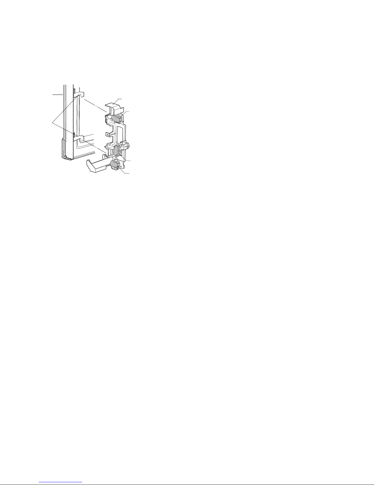
[1] DOOR OPEN MECHANISM
The door is opened by pushing the open button on the control panel,
refer to the Figure D-1.When the open button is pushed, the open button pushes up the switch lever, and then the switch lever pushes up
the latch head. The latch heads are moved upward and released from
latch hook. Now the door will open.
Figure D-1. Door Open Mechanism
[2] 1ST. LATCH SWITCH AND 2ND. INTERLOCK RELAY CONTROL SWITCH
1. When the oven door is closed, the contacts (COM-NO) must be
closed.
2. When the oven door is opened, the contacts (COM-NO) must be
opened.
[3] MONITOR SWITCH
1. When the oven door is closed, the contacts (COM-NC) must be
opened.
2. When the oven door is opened, the contacts (COM-NC) must be
closed.
3. If the oven door is opened and the contacts (COM-NO) of the 1st.
latch switch and 2nd. interlock relay fail to pen, the fuse F10A
blows simultaneously with closing the contacts (COM-NC) of the
monitor switch.
CAUTION: BEFORE REPLACING A BLOWN FUSE F10A TEST THE
1ST. LATCH SWITCH, 2ND.INTERLOCK RELAY, MONITOR SWITCHAND MONITOR RESISTOR FOR PROPEROPERATION.
[4] FUSE F10A
1. The fuse F10A blows when the contacts (COM-NO) oft he 1st. latch
switch and 2nd. interlock relay remain closed with the oven door
open and when the monitor witch closes.
2. If the wire harness or electrical components are short-circuited, this
fuse F10A blows to prevent an electric shock or fire hazard.
[5] HIGH VOLTAGE FUSE
The high voltage fuse blows when the high voltage rectifier or the magnetron is shorted.
[6] OVEN TEMPERATURE FUSE
The temperature fuse, located on the top of the oven cavity, is
designed to prevent damage to the oven by fire.If the food load is overcooked, by either error in cook time or defect in the control unit, the
temperature fuse will open.Under normal operation, the temperature
fuse remains closed. However, when abnormally high temperatures
are reached within the oven cavity, the temperature fuse will open at
150°C, causing the oven to shut down.
[7] TURNTABLE MOTOR
The turntable motor drives the turntable roller assembly to rotate the
turntable.
[8] FAN MOTOR
The fan motor drives a blade which draws external cool air.This cool
air is directed through the air vents surrounding the magnetron and
cools the magnetron. This air is channelled through the oven cavity to
remove steam and vapours given off from the heating foods. It is then
exhausted through the exhausting air vents at the oven cavity.
[9] NOISE FILTER
The noise filter prevents the radio frequency interference that might
flow back in the power circuit.
Latch Hook
Monitor Switch
2nd. Interlock
Relay Control
Switch
1st Latch Switch
Latch
Heads
Door

R395N(S)
7 – 1
R395N(S)
ServiceManual
CHAPTER 7. TROUBLESHOOTING GUIDE
[1] FOREWORD
When troubleshooting the microwave oven, it is helpful to follow the
Sequence of Operation in performing the checks. Many of the possible
causes of trouble will require that a specific test be performed. These
tests are given a procedure letter which will be found in the “Test Procedure”section.
IMPORTANT:
If the oven becomes inoperative because of a blown fuse F10A in the
1st. latch switch - 2nd. interlock relay - monitor switch circuit, check the
1st. latch switch, 2nd.interlock relay and monitor switch before replacing the fuse F10A.
[2] CHART
MAGNETRON
POWER TRANSFORMER
H.V. RECTIFIER ASSEMBLY
HIGH VOLTAGE CAPACITOR
1ST. LATCH SWITCH
2ND. INTERLOCK RELAY CONTROL
SWITCH
MONITOR SWITCH
TEMPERATURE FUSE (OVEN)
FAN MOTOR
TURNTABLE MOTOR
FUSE F10A
TOUCH CONTROL PANEL
KEY UNIT
RELAY (RY-1, RY-2)
FOIL PATERN ON P.W.B.
POWER SUPPLY CORD
SHORTED WIRE HARNESS
OPENED WIRE HARNESS
OVEN LAMP
WALL OUTLET
MISADJUSTMENT SWITCH
HOME FUSE OR BREAKER
BLOCKED COOLING FAN
BLOCKED VENTILATION
NOISE FILTER
HIGH VOLTAGE FUSE
TEST PROCEDURE
CK = Check / RE = Replace
ABC
D
EEEFGGHKLMN
RE CK CK RE CK CK CK CK CK
IJ
CONDITION
PROBLEM
POSSIBLE CAUSE
AND
DEFECTIVE PARTS
ON
CONDITION
OFF
CONDITION
Home fuse blows when power
supply cord is plugged into wall
outlet.
FUSE F10A blows when power
supply cord is plugged into wall
outlet.
Display does not show anything
when power supply cord is plugged into wall outlet.
Display does not operate properly when STOP/CLEAR pad is
touched.
Oven lamp does not light at door
opened. (Display appears.)
Oven lamp does not light (Display appears.)
Fan motor does not operate.
(Display appears.)
Turntable motor assembly does
not operate. (Display appears.)
Oven does not start when the
START pad is touched. (Display appears)
Oven or any electrical parts does
not stop when cooking time is 0
or STOP/CLEAR pad is touched.
Oven goes into cook cycle but
shuts down before end of cooking cycle.
Oven seems to be operating but
little or no heat is produced in
oven load. (Microwave power level is set at 100%)
Oven does not seems to be operating properly when 70%, 50%,
30% or 10% is set. (Oven operates properly at 100% and then
the STOP/CLEAR pad is touched
the oven stops.)
 Loading...