

Page 1
TopPage
PRO-60/70X5FD
SERVICE MANUAL
No. S81S7PR60X5FD
LCD COLOR TELEVISION
PRO-60X5FD
MODELS
In the interests of user-safety (Required by safety regulations in some countries) the set should be restored to its original condition and only parts identical to those specified should be used.
PRO-70X5FD
CONTENTS
SAFETY PRECAUTION
IMPORTANT SERVICE SAFETY
PRECAUTION.....................................................i
PRECAUTIONS A PRENDRE LORS DE
LA REPARATION...............................................ii
PRECAUTIONS FOR USING LEAD-FREE
SOLDER ........................................................... iii
OUTLINE
MAJOR SERVICE PARTS ................................ iv
CHAPTER 1. SPECIFICATIONS
[1] SPECIFICATIONS ......................................... 1-1
CHAPTER 2. OPERATION MANUAL
[1] Parts Name .................................................... 2-1
[2] OPERATION MANUAL .................................. 2-3
CHAPTER 3. DIMENSIONS
[1] DIMENSIONS (PRO-60X5FD)....................... 3-1
[2] DIMENSIONS (PRO-70X5FD)....................... 3-2
CHAPTER 4. REMOVING OF MAJOR PARTS
[1] REMOVING OF MAJOR PARTS
(PRO-60X5FD)............................................... 4-1
[2] REMOVING OF MAJOR PARTS
(PRO-70X5FD)............................................... 4-6
[3] The location putting on the heat measure
sheet ............................................................ 4-11
[4] Precautions for assembly............................. 4-12
[5] The way of detaching Rear Cabinet
Ass'y............................................................. 4-14
CHAPTER 5. ADJUSTMENT
[1] ADJUSTMENT PROCEDURE ......................5-1
[2] PUBLIC MODE SETTING
PROCEDURE..............................................5-16
CHAPTER 6. TROUBLESHOOTING TABLE
[1] Failure diagnosis by LED in front of
cabinet ...........................................................6-1
[2] LED flashing specification at the time of an
error (Power LED used).................................6-1
[3] TROUBLESHOOTING TABLE ......................6-5
CHAPTER 7. MAJOR IC INFORMATIONS
[1] MAJOR IC INFORMATIONS .........................7-1
CHAPTER 8. OVERALL WIRING/SYSTEM BLOCK
DIAGRAM
[1] OVERALL WIRING DIAGRAM
(PRO-60X5FD) ..............................................8-1
[2] OVERALL WIRING DIAGRAM
(PRO-70X5FD) ..............................................8-2
[3] SYSTEM BLOCK DIAGRAM .........................8-3
Parts Guide
Parts marked with " " are important for maintaining the safety of the set. Be sure to replace these parts with specified ones for maintaining the
safety and performance of the set.
This document has been published to be used for
after sales service only.
The contents are subject to change without notice.
Page 2
PRO-60/70X5FD
PRO60X5FD
SAFETY PRECAUTION
Service Manual
IMPORTANT SERVICE SAFETY PRECAUTION
Service work should be performed only by qualified service technicians who are thoroughly familiar with all safety checks and the
servicing guidelines which follow:
WARNING
1. For continued safety, no modification of any circuit should be
attempted.
2. Disconnect AC power before servicing.
CAUTION: FO R CO NT I NU ED PROTECTION
AGAINST A RISK OF FIRE REPLACE ONLY WITH
SAME TYPE FUSE.
F001, F002 (250V 10A)
BEFORE RETURNING THE RECEIVER (Fire &
Shock Hazard)
Before returning the receiver to the user, perform the following
safety checks:
3. Inspect all lead dress to make certain that leads are not pinched,
and check that hardware is not lodged between the chassis and
other metal parts in the receiver.
4. Inspect all protective devices such as non-metallic control knobs,
insulation materials, cabinet backs, adjustment and compartment
covers or shields, isolation resistor-capacitor networks, mechanical
insulators, etc.
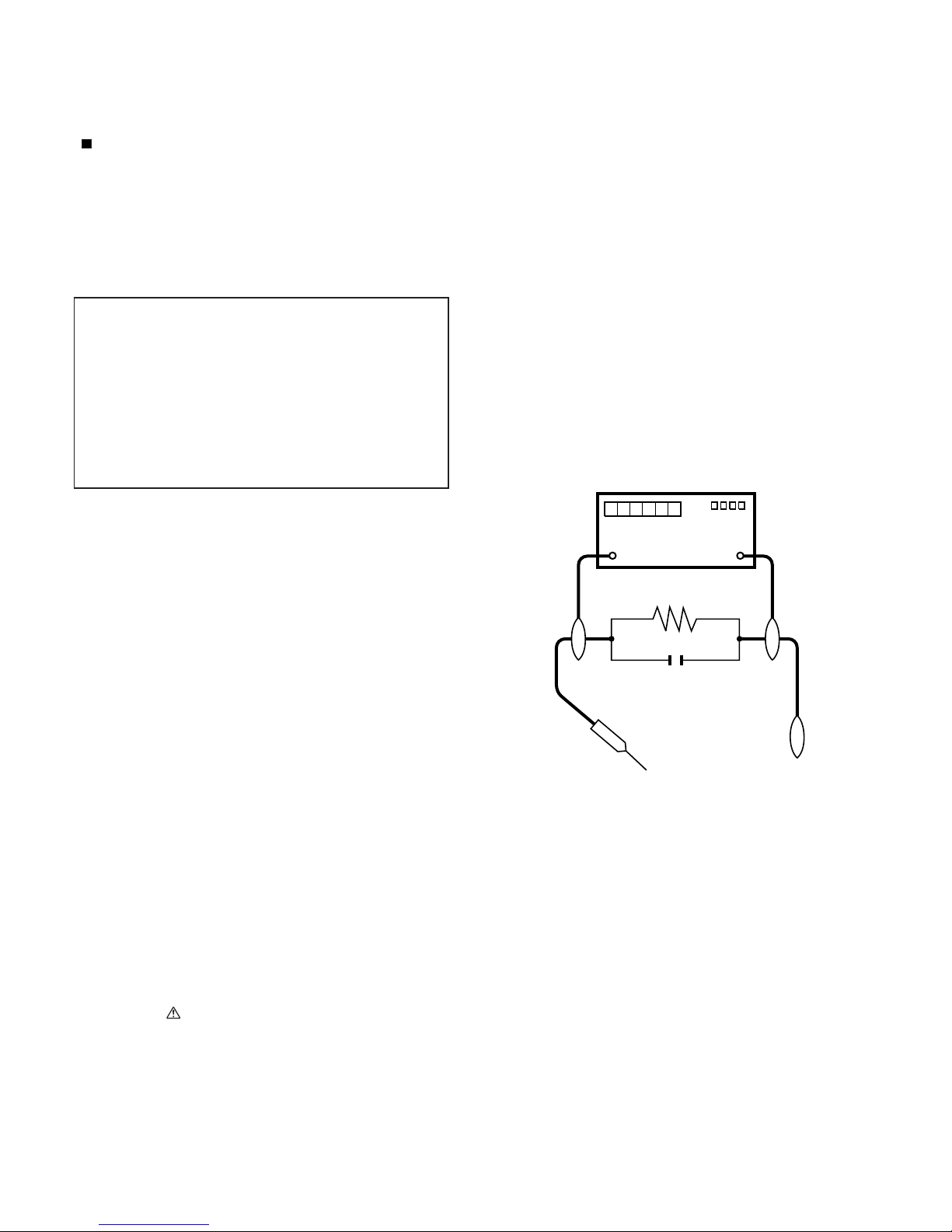
5. To be sure that no shock hazard exists, check for leakage current
in the following manner.
• Plug the AC cord directly into a 120 volt AC outlet.
• Using two clip leads, connect a 1.5k ohm, 10 watt resistor paralleled by a 0.15µF capacitor in series with all exposed metal cabinet
parts and a known earth ground, such as electrical conduit or electrical ground connected to an earth ground.
• Use an AC voltmeter having with 5000 ohm per volt, or higher, sensitivity or measure the AC voltage drop across the resistor.
• Connect the resistor connection to all exposed metal parts having a
return to the chassis (antenna, metal cabinet, screw heads, knobs
and control shafts, escutcheon, etc.) and measure the AC voltage
drop across the resistor.
All checks must be repeated with the AC cord plug connection
reversed. (If necessary, a nonpolarized adaptor plug must be used
only for the purpose of completing these checks.)
Any reading of 0.75 Vrms (this corresponds to 0.5 mA rms AC.) or
more is excessive and indicates a potential shock hazard which
must be corrected before returning the monitor to the owner.
DVM
AC SCALE
1.5k ohm
10W
0.15µF
TEST PROBE
TO EXPOSED
METAL PARTS
CONNECT TO
KNOWN EARTH
GROUND
///////////////////////////////////////////////////////////////////////////////////////////////////////////////////////////////////////////////////////////////////////////////////////////////////////////////////////////////////////////
SAFETY NOTICE
Many electrical and mechanical parts in LCD color television have
special safety-related characteristics.
These characteristics are often not evident from visual inspection, nor
can protection afforded by them be necessarily increased by using
replacement components rated for higher voltage, wattage, etc.
Replacement parts which have these special safety characteristics are
identified in this manual; electrical components having such features
are identified by " " and shaded areas in the Replacement Parts List
and Schematic Diagrams.
///////////////////////////////////////////////////////////////////////////////////////////////////////////////////////////////////////////////////////////////////////////////////////////////////////////////////////////////////////////
For continued protection, replacement parts must be identical to those
used in the original circuit.
The use of a substitute replacement parts which do not have the same
safety characteristics as the factory recommended replacement parts
shown in this service manual, may create shock, fire or other hazards.
i
Page 3
PRO-60/70X5FD
PRECAUTIONS A PRENDRE LORS DE LA REPARATION
Ne peut effectuer la réparation qu' un technicien spécialisé qui s'est parfaitement accoutumé à toute vérification de sécurité et aux
conseils suivants.
•
AVERTISSEMENT
1.
N'entreprendre aucune modification de tout circuit. C'est dangereux.
2.
Débrancher le récepteur avant toute réparation.
PRECAUTION: POUR LA PROTECTION CONTINUE CONTRE LES RISQUES D'INCENDIE,
REMPLACER LE FUSIBLE
F001, F002 (250V 10A)
VERIFICATIONS CONTRE L'INCEN-DIE ET LE
CHOC ELECTRIQUE
Avant de rendre le récepteur à l'utilisateur, effectuer les vérifications suivantes.
3.
Inspecter tous les faisceaux de câbles pour s'assurer que les fils
ne soient pas pincés ou qu'un outil ne soit pas placé entre le châssis et les autres pièces métalliques du récepteur.
4.
Inspecter tous les dispositifs de protection comme les boutons de
commande non-métalliques, les isolants, le dos du coffret, les couvercles ou blindages de réglage et de compartiment, les réseaux
de résistancecapacité, les isolateurs mécaniques, etc.
5.
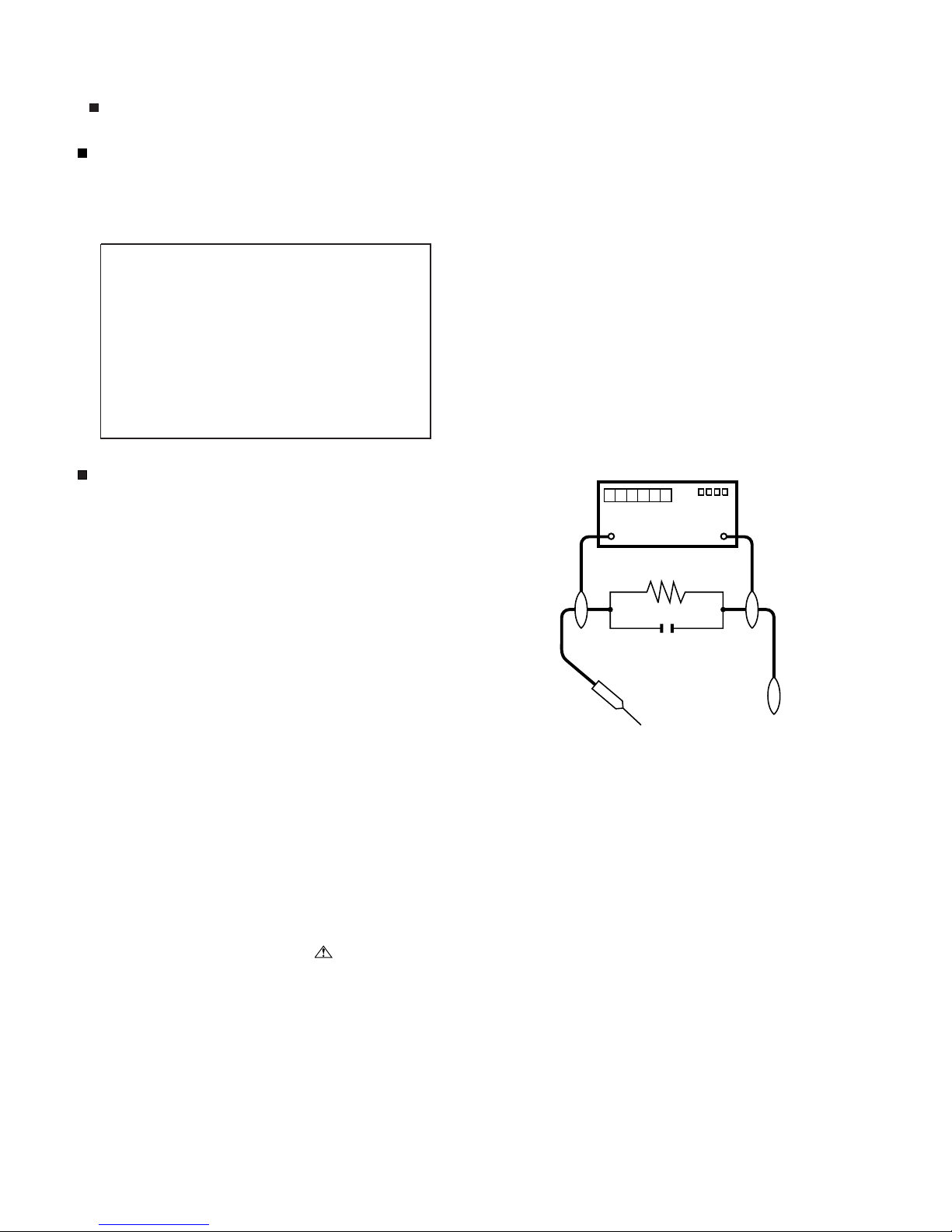
S'assurer qu'il n'y ait pas de danger d'électrocution en vérifiant la
fuite de courant, de la facon suivante:
•
Brancher le cordon d'alimentation directem-ent à une prise de courant de 120V. (Ne pas utiliser de transformateur d'isolation pour
cet essai).
A l'aide de deux fils à pinces, brancher une résistance de 1.5 kΩ
10 watts en parallèle avec un condensateur de 0.15µF en série
avec toutes les pièces métalliques exposées du coffret et une terre
connue comme une conduite électrique ou une prise de terre
branchée à la terre.
•
Utiliser un voltmètre CA d'une sensibilité d'au moins 5000Ω/V pour
mesurer la chute de tension en travers de la résistance.
•
Toucher avec la sonde d'essai les pièces métalliques exposées qui
présentent une voie de retour au châssis (antenne, coffret métallique, tête des vis, arbres de commande et des boutons, écusson,
etc.) et mesurer la chute de tension CA en-travers de la résistance.
Toutes les vérifications doivent être refaites après avoir inversé la
fiche du cordon d'alimentation. (Si nécessaire, une prise
d'adpatation non polarisée peut être utilisée dans le but de terminer ces vérifications.)
La tension de pointe mesurèe ne doit pas dépasser 0.75V (correspondante au courant CA de pointe de 0.5mA).
Dans le cas contraire, il y a une possibilité de choc électrique qui
doit être supprimée avant de rendre le récepteur au client.
DVM
ECHELLE CA
1.5k ohm
10W
µ
F
0.15
SONDE D'ESSAI
AUX PIECES
METALLIQUES
EXPOSEES
BRANCHER A UNE
TERRE CONNUE
/////////////////////////////////////////////////////////////////////////////////////////////////////////////////////////////////////////////////////////////////////////////////////////////////////////////////////////////////////////////
AVIS POUR LA SECURITE
De nombreuses pièces, électriques et mécaniques, dans les téléviseur ACL présentent des caractéristiques spéciales relatives à la sécurité, qui ne sont souvent pas évidentes à vue. Le degré de protection ne peut pas être nécessairement augmentée en utilisant des
pièces de remplacement étalonnées pour haute tension, puissance,
etc.
Les pièces de remplacement qui présentent ces caractéristiques sont
identifiées dans ce manuel; les pièces électriques qui présentent ces
particularités sont identifiées par la marque " " et hachurées dans la
liste des pièces de remplacement et les diagrammes schématiques.
/////////////////////////////////////////////////////////////////////////////////////////////////////////////////////////////////////////////////////////////////////////////////////////////////////////////////////////////////////////////
Pour assurer la protection, ces pièces doivent être identiques à celles
utilisées dans le circuit d'origine. L'utilisation de pièces qui n'ont pas
les mêmes caractéristiques que les pièces recommandées par l'usine,
indiquées dans ce manuel, peut provoquer des électrocutions, incendies, radiations X ou autres accidents.
ii
Page 4
PRO-60/70X5FD
PRECAUTIONS FOR USING LEAD-FREE SOLDER
Employing lead-free solder
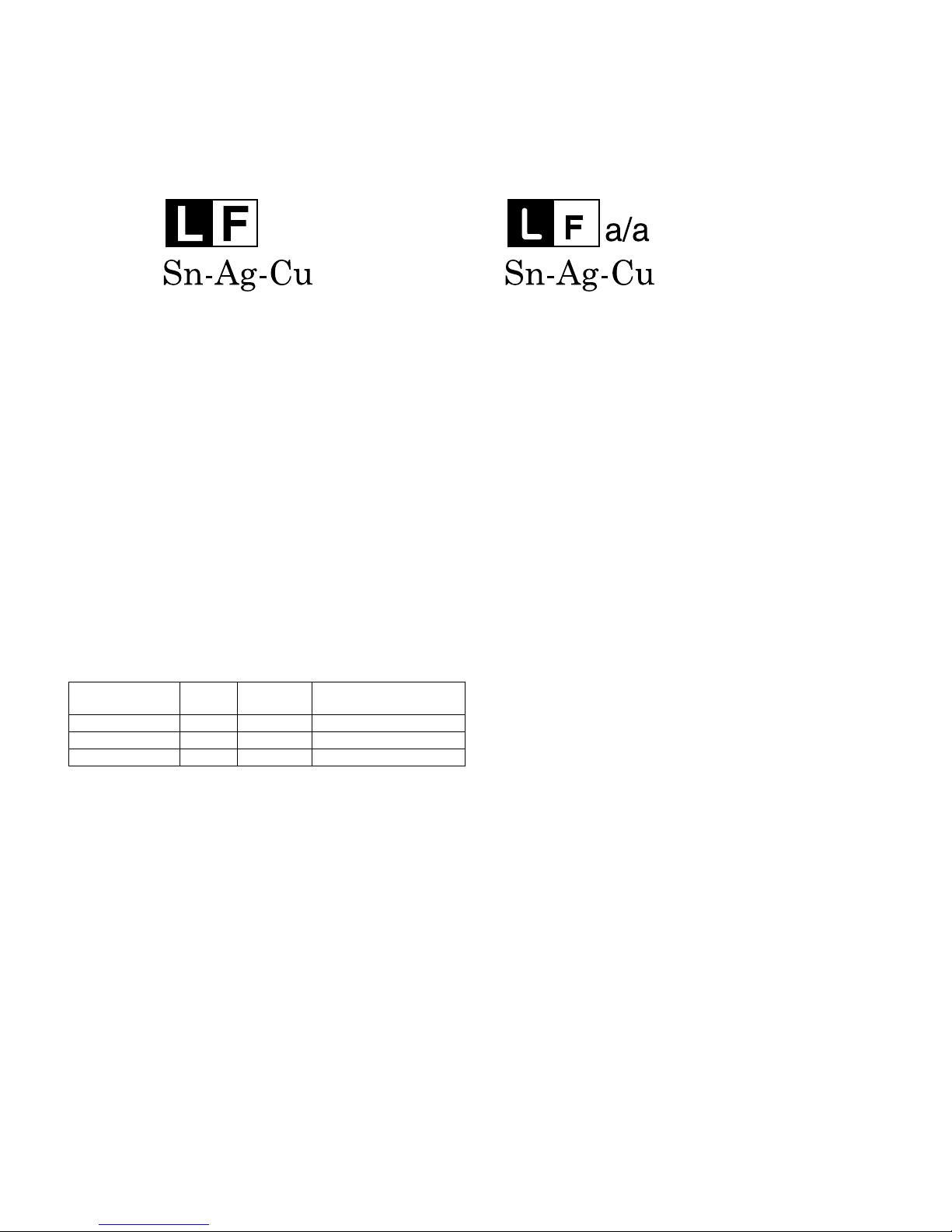
• “PWBs” of this model employs lead-free solder. The LF symbol indicates lead-free solder, and is attached on the PWBs and service manuals. The
alphabetical character following LF shows the type of lead-free solder.
Example:
Indicates lead-free solder of tin, silver and copper. Indicates lead-free solder of tin, silver and copper.
Using lead-free wire solder
• When fixing the PWB soldered with the lead-free solder, apply lead-free wire solder. Repairing with conventional lead wire solder may cause damage or accident due to cracks.
As the melting point of lead-free solder (Sn-Ag-Cu) is higher than the lead wire solder by 40 °C, we recommend you to use a dedicated soldering
bit, if you are not familiar with how to obtain lead-free wire solder or soldering bit, contact our service station or service branch in your area.
Soldering
• As the melting point of lead-free solder (Sn-Ag-Cu) is about 220 °C which is higher than the conventional lead solder by 40 °C, and as it has poor
solder wettability, you may be apt to keep the soldering bit in contact with the PWB for extended period of time. However, Since the land may be
peeled off or the maximum heat-resistance temperature of parts may be exceeded, remove the bit from the PWB as soon as you confirm the
steady soldering condition.
Lead-free solder contains more tin, and the end of the soldering bit may be easily corroded. Make sure to turn on and off the power of the bit as
required.
If a different type of solder stays on the tip of the soldering bit, it is alloyed with lead-free solder. Clean the bit after every use of it.
When the tip of the soldering bit is blackened during use, file it with steel wool or fine sandpaper.
• Be careful when replacing parts with polarity indication on the PWB silk.
Lead-free wire solder for servicing
PARTS CODE
ZHNDAi123250E BL J φ0.3mm 250g (1roll)
ZHNDAi126500E BK J φ0.6mm 500g (1roll)
ZHNDAi12801KE BM J φ1.0mm 1kg (1roll)
PRICE
RANK
PART
DELIVERY
DESCRIPTION
iii
Page 5
PRO60X5FD
OUTLINE
Service Manual
MAJOR SERVICE PARTS
PWB Unit
Ref No Parts No Description
N DKEYMF733FM21 MAIN Unit (PRO-60X5FD) (*1)
N DKEYMF733FM20 MAIN Unit (PRO-70X5FD) (*1)
N DUNTKF909FM01 R/C OPC Unit
N DUNTKF800FM50 KEY Unit
N RUNTKA810WJQZ WiFi Unit
N RUNTKA819WJQZ 3D IR EMITTER Unit
N RDENCA418WJQZ POWER Unit (PRO-60X5FD)
N RDENCA446WJQZ POWER Unit (PRO-70X5FD)
N RUNTKA841WJZZ LED DRIVE Unit (PRO-60X5FD)
N RUNTKA838WJZZ LED DRIVE Unit (PRO-70X5FD)
N RUNTK4908TPZA LCD Control Unit (PRO-60X5FD)
N RUNTK4908TPZF LCD Control Unit (PRO-70X5FD)
NOTE: *1 Replace MAIN PWB Units (DKEYMF733FM**) in case of IC8401, IC3303 or IC8455 failure.
OTHER Unit
Ref No. Parts No. Description
N R1LK600D3GW60Z 60" LCD Panel Module Unit (LK600D3GW60Z) (PRO-60X5FD)
N R1LK695D3GW10Z 70" LCD Panel Module Unit (LK695D3GW10Z) (PRO-70X5FD)
PRO-60/70X5FD
IC For Exclusive Use Of The Service
Ref No. Parts No. Description Q'ty
IC2001 RH-iXD241WJNCQ IC R5F21368CNFP (Monitor Microcomputer) 1
Service Jigs
Ref No. Parts No. Description Q'ty
N QCNW-C222WJQZ Connecting Cord L=1000mm, 80pins, LCD Control Unit to LCD Panel Unit 2
N QCNW-L214WJQZ Connecting Cord L=1000mm, 64pins, LCD Control Unit to LCD Panel Unit 2
N QCNW-F676WJQZ Connecting Cord L=1000mm, 41pins, Main to LCD Control Unit (LW) 1
N QCNW-L795WJQZ Connecting Cord L=1000mm, 24pins, Main to POWER Unit (PD) 1
N QCNW-G405WJQZ Connecting Cord L=1000mm, 4pins, Power to LCD Control Unit (PL) 1
N QCNW-L519WJQZ Connecting Cord L=1000mm, 18pins, Power to LED Drive Unit (LA) 1
N QCNW-F139WJQZ Connecting Cord L=1000mm, 13pins, LCD Control Unit to LED Drive Unit (LB) 1
iv
Page 6
PRO-60/70X5FD
PRO60X5FD
CHAPTER 1. SPECIFICATIONS
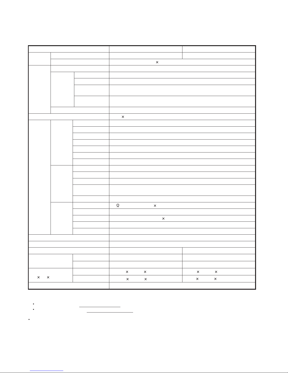
[1] SPECIFICATIONS
Service Manual
Item Model: PRO-70X5FD Model: PRO-60X5FD
LCD
panel
1
Size 70" Class (69
/
" Diagonal)
2
Resolution 2,073,600 pixels (1,920
60" Class (60
1,080)
1
/
" Diagonal)
32
TV-standard (CCIR) American TV Standard ATSC/NTSC System
VHF/UHF VHF 2-13ch, UHF 14-69ch
CATV 1-135ch (non-scrambled channel only)
TV
Function
Receiving
Channel
Digital Terrestrial
Broadcast (8VSB)
Digital cable
*1
(64/256 QAM)
2-69ch
1-135ch (non-scrambled channel only)
Audio multiplex BTSC System
Audio out 15W 2 + 15 W (WF)
HDMI 1 HDMI in with HDCP, Audio in (Ø 3.5 mm stereo jack)
HDMI 2 HDMI in with HDCP
Back panel
vertical
inputs
HDMI 3 HDMI in with HDCP
HDMI 4 HDMI in with HDCP
HDMI 5 HDMI in with HDCP
AUDIO OUT Audio out (Ø 3.5 mm stereo jack)
USB 1
*2
Photo/Music/Video mode, Software update
COMPONENT COMPONENT in
Terminals
Back panel
surface
inputs
VIDEO 1 AV in
VIDEO 2 AV in
PC IN
ANALOG RGB (PC) in (15-pin mini D-sub female connector),
Audio in (Ø 3.5 mm stereo jack)
RS-232C 9-pin D-sub male connector
75 Unbalance, F Type 1 for Analog (VHF/UHF/CATV) and Digital (AIR/CABLE)
Optical Digital audio output 1 (PCM/Dolby Digital)
Back panel
horizontal
inputs
ANT/CABLE
AUDIO IN Audio in (Ø 3.5 mm stereo jack)
DIGITAL AUDIO OUTPUT
ETHERNET Network connector
USB 2 Photo/Music/Video mode, Software update
OSD language English/French/Spanish
Power Requirement AC 120 V, 60 Hz
Power Consumption
Weight
Dimension
*3
(W H D)
TV + stand 101.4 lbs./46.0 kg 71.7 lbs./32.5 kg
TV only 94.8 lbs./43.0 kg 66.1 lbs./30.0 kg
TV + stand 63
TV only 63
Operating temperature
*1
Emergency alert messages via Cable are unreceivable.
*2
Skype will be available only for the USB 1 terminal. For details, refer to the following:
282 W (0.13 W Standby with AC 120 V) 204 W (0.1 W Standby with AC 120 V)
61
/64403/64131/8inch 551/83413/16131/8inch
61
/643843/
31/32inch 551/8337/1631/32inch
64
+32°F to +104°F (0°C to +40°C)
For Skype information (http://www.skype.com)
For Operating Instructions (http://www.elitelcdtv.com)
*3
The dimensional drawings are shown on the inside back cover.
As part of policy of continuous improvement, SHARP reserves the right to make design and specification changes for
product improvement without prior notice. The performance specification figures indicated are nominal values of production
units. There may be some deviations from these values in individual units.
1 – 1
Page 7
PRO60X5FD
CHAPTER 2. OPERATION MANUAL
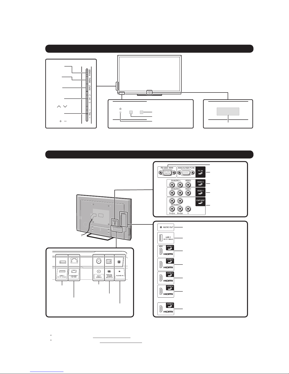
[1] Parts Name
TV (Front/Side)
*1
POWER
button
MENU
button
INPUT
button
Channel
buttons
(CH /)
Volume
buttons
(VOL /)
*1 Button operations.
*2 OPC: Optical Picture Control
*3 This panel emits the infrared signal towards the 3D Glasses you wear when you view 3D images.
Do not place anything between the 3D infrared emitter on the TV and the infrared receiver on the 3D Glasses.
Service Manual
OPC sensor *2
Remote control sensor
Power LED
PRO-60/70X5FD
3D infrared emitter *3
TV (Rear)
USB 2
terminal
ETHERNET
terminal
Antenna/
Cable in
DIGITAL AUDIO
OUTPUT terminal
AUDIO IN terminal
(shared for PC IN
and HDMI 1) *2
RS-232C terminal
PC IN terminal
VIDEO 2 terminals
VIDEO 1 terminals
COMPONENT
terminals
AUDIO OUT terminal
USB 1 terminal *3
*1
HDMI 1 terminal
ARC: Audio Return Channel
HDMI 2 terminal
HDMI 3 terminal
HDMI 4 terminal
HDMI 5 terminal
*1
*1
*1 External equipment connection.
*2 Details on the Audio Select function.
*3 Skype will be available only for the USB 1 terminal. For details, refer to the following:
For Skype information (http://www.skype.com)
For Operating Instructions (http://www.elitelcdtv.com)
2 – 1
Page 8
PRO-60/70X5FD
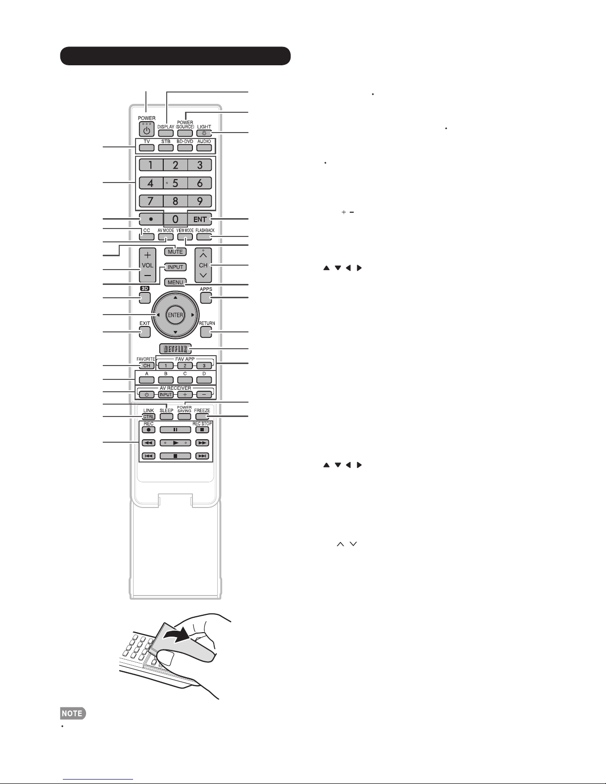
Remote Control Unit
10
11
12
13
14
15
16
17
18
1
19
20
21
2
3
4
5
6
22
23
24
7
8
9
25
26
27
28
29
30
31
32
1 POWER: Switch the TV power on or enter standby.
2TV, STB, BD DVD, AUDIO: Switches the remote control for
TV, STB, BD, DVD and AUDIO operation.
* To enter the code registration mode, you need to press
an appropriate button (STB, BD DVD or AUDIO)and
DISPLAY at the same time.
30-9: Set the channel.
4 (DOT)
5 CC: Display captions from a closed-caption source.
6 AV MODE: Select an audio or video setting.
7 MUTE: Mute the sound.
8 VOL / : Set the volume.
9INPUT:Select a TV input source. (TV, HDMI1, HDMI2,
HDMI3, HDMI4, HDMI5, COMPONENT, VIDEO1, VIDEO2, PC
IN, Home Network (DLNA), USB)
10 3D: Select between 3D and 2D image viewing.
11 ///,ENTER: Select a desired item on the screen.
12 EXIT: Turn off the menu screen.
13 FAVORITE CH: Set the favorite channels.
14 A, B, C, D: Select 4 preset favorite channels in 4 different
categories.
While watching, you can toggle the selected channels by
pressing A, B, C and D.
15 AV RECEIVER: Operate an AV receiver.
16 SLEEP: Set the sleep timer.
17 LINK CTRL: Display the Link Operation Menu screen. This
button will function only when Link Control is used.
18 External equipment operational buttons: Operate the
external equipment.
19 DISPLAY: Display the channel information.
20 POWER (SOURCE): Turns the power of the external
equipment on and off.
21 LIGHT: When this button is pressed, all buttons (except
/
/ / and the buttons under the cover) on the remote
control unit will light. The lighting will turn off if no operations
are performed within about 5 seconds.
22 ENT: Jumps to a channel after selecting with the 0-9 buttons.
23 FLASHBACK: Return to the previous channel or external
input mode.
24 VIEW MODE: Select the screen size.
25 CH /
26 MENU: Display the menu screen.
27 APPS: Display the application window.
28 RETURN: Return to the previous menu screen.
29 NETFLIX: Display the Netflix screen.
30 FAV APP 1, 2, 3: You can assign your favorite applications to
these buttons.
31 POWER SAVING: Select Power Saving settings.
32
FREEZE: Set the still image. Press again to return to normal
screen.
: Select the channel.
When using the remote control unit, point it at the TV.
2 – 2
Page 9
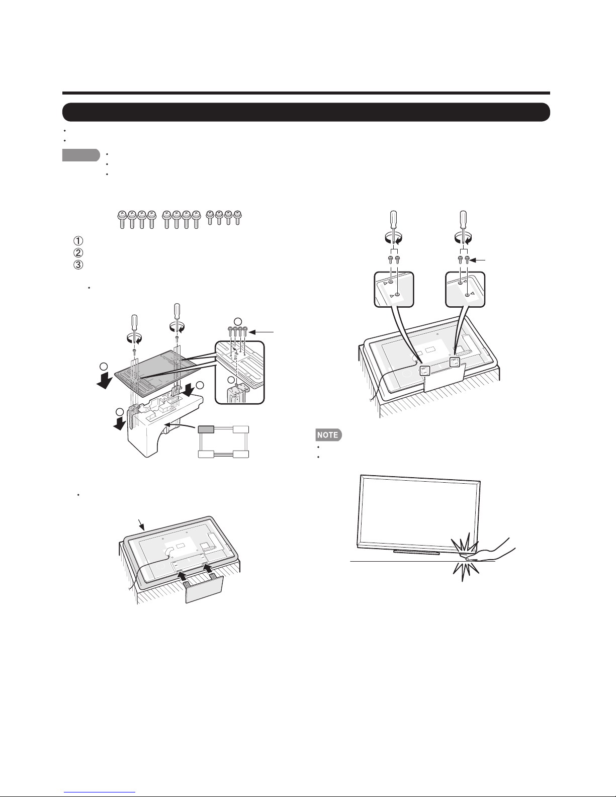
[2] OPERATION MANUAL
QUICK REFERENCE
Attaching the Stand
Before attaching (or detaching) the stand, unplug the AC cord.
Before performing work spread cushioning over the base area to lay the TV on. This will prevent it from being damaged.
CAUTION
Confirm that there are 12 screws (8 long screws
1
and 4 short screws) supplied with the stand unit.
2
Attach the stand in the correct direction.
Do not remove the stand from the TV unless using an optional wall mount bracket to mount it.
Be sure to follow the instructions. Incorrect installation of the stand may result in the TV falling over.
Insert and tighten the 4 screws into the 4 holes on
4
the rear of the TV.
Set the post for the stand unit onto the box.
Attach the base to the post.
Insert and tighten the 8 screws into the 8 holes
on the bottom of the base.
Hold the stand unit securely with one hand, and then
tighten the screws.
PRO-60/70X5FD
Short screws
2
2
1
1
Insert the stand into the openings on the bottom of the
3
TV.
Make sure that the stand is firmly inserted into the TV.
Improper installation may result in tilting of the TV set.
Soft cushion
1
FRONT
Long
screws
To detach the stand, perform the steps in reverse order.
In the installation procedure, be careful not to catch your
fingers between the TV set and the floor.
2 – 3
Page 10
PRO-60/70X5FD
PRO60X5FD
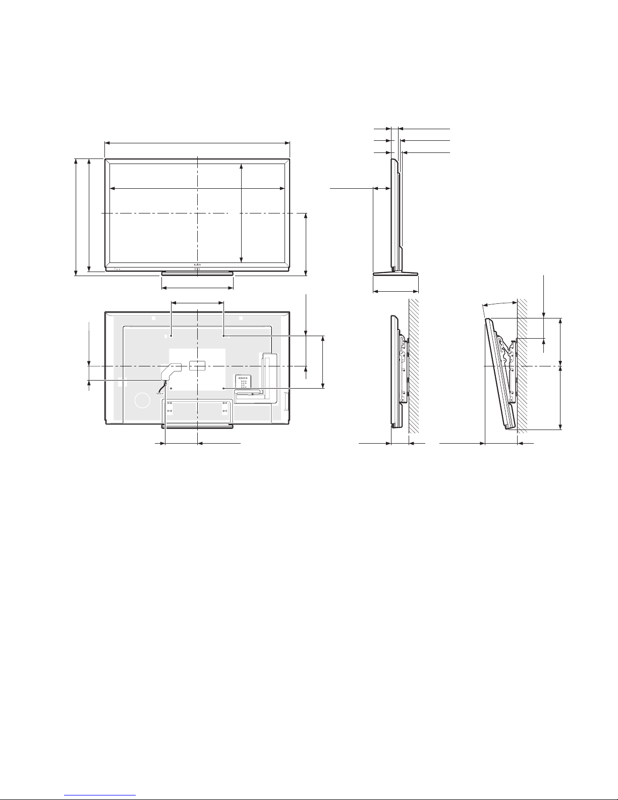
CHAPTER 3. DIMENSIONS
[1] DIMENSIONS (PRO-60X5FD)
1
/
55
(1400)
8
Service Manual
Unit: inch (mm)
/
4
/
/
32
(44.3)
(59)
64
(77)
*2
3
1
21
2
1
3
(884)
16
/
7
13
34
1
*1
Active area
*2
Thinnest part
(849)
16
/
33
(108)
4
/
4
52
11
/
(1329.12)
32
21
15
*1
*1
25
/
5
(137)
64
(747.63)
16
/
7
29
(475)
64
/
45
18
7
/
(536)
64
3
/
(400)
4
(230)
16
/
1
9
(400)
4
/
3
13
1
/
(333)
8
10°
(149)
8
/
7
5
(387)17
4
/
1
15
15
(449)
16
/
11
5
/
9
(244) 5 (127) 9
8
11
/
(237)
32
AN-52AG4
3 – 1
Page 11
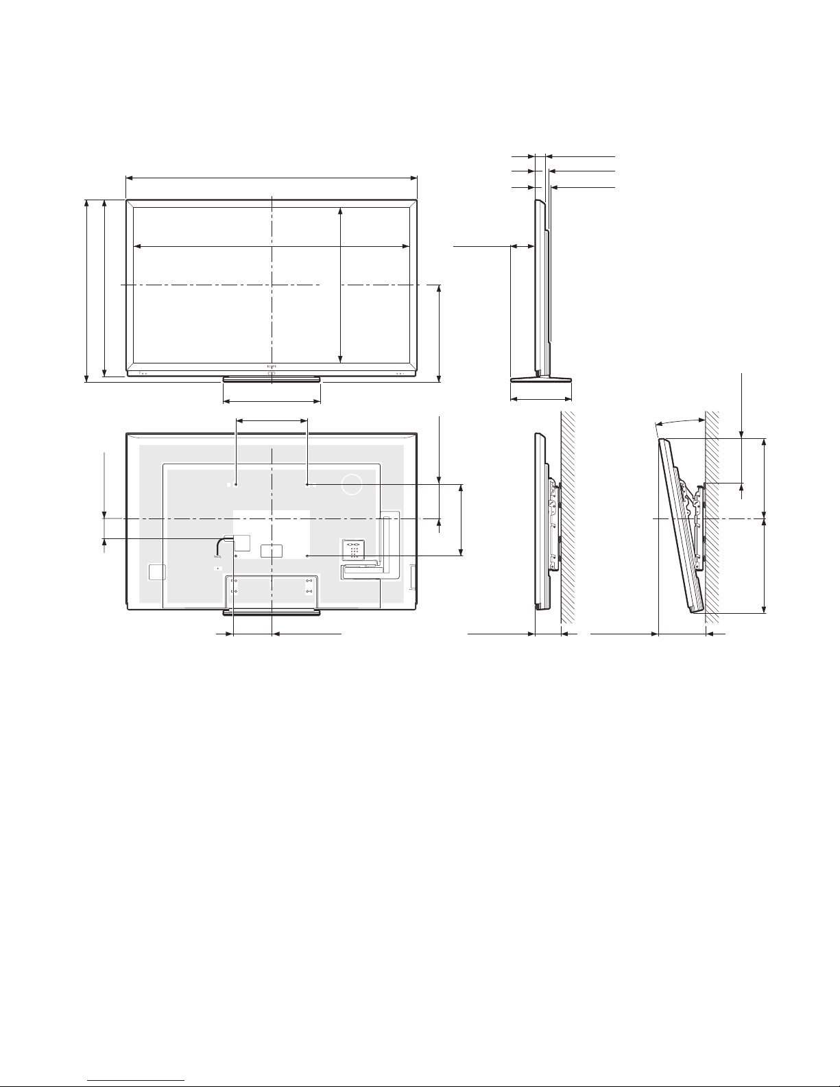
[2] DIMENSIONS (PRO-70X5FD)
PRO-60/70X5FD
Unit: inch (mm)
(1017)
64
/
3
40
(982)
64
/
43
38
(115)
32
/
17
4
60
19
/
(1538.88)
32
63
21
15
63
1
61
/
(1624)
64
*1
*1
25
/
5
(137)
64
2
3
*2
/
(50)
64
47
/
(69)
64
1
/
(77)
32
(865.62)
32
/
3
34
(543)
64
/
25
21
7
/
(536)
64
3
/
(400)
4
(190)
64
/
31
7
(400)
4
/
3
15
13
1
/
(333)
8
10°
(250)
32
/
27
9
(449)20
16
/
11
17
(518)
64
/
25
*1
Active area
*2
Thinnest part
23
/
5
(215)
64
23
/
5
(136)
64
10
25
/
(264)
64
AN-52AG4
3 – 2
Page 12
PRO-60/70X5FD
PRO60X5FD
CHAPTER 4. REMOVING OF MAJOR PARTS
Service Manual
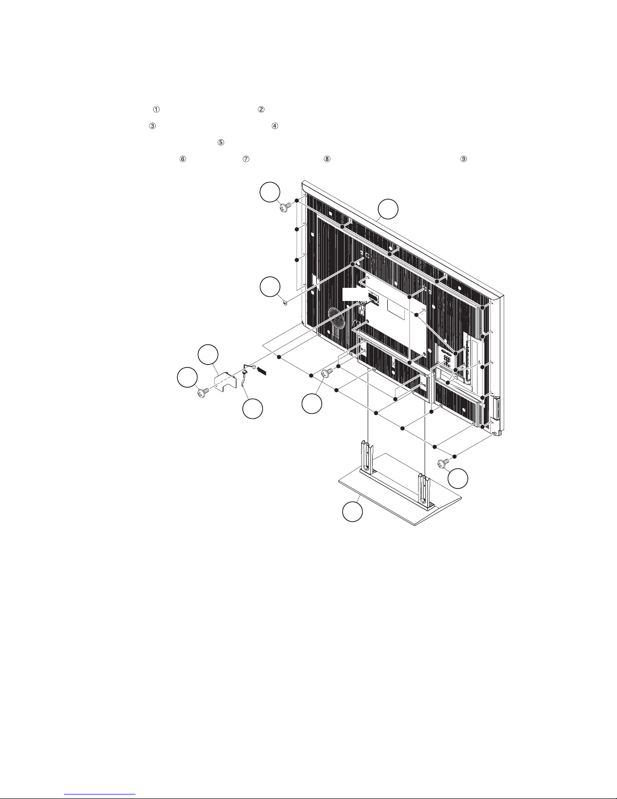
[1] REMOVING OF MAJOR PARTS (PRO-60X5FD)
1. Removing of Stand Unit and Rear Cabinet Ass’y.
1. Remove the 4 lock screws and detach the Stand Unit .
2. Remove the 1 lock screw and detach the AC Cord Cover .
3. Disconnect AC wire and detach the AC Cord .
4. Remove the 4 VESA Hole Covers , 9 lock screws and 18 lock screws and detach the Rear Cabinet Ass’y .
8
Rear Cabinet Ass'y
9
VESA Hole Cover
AC Cord Cover
4
3
AC Cord
6
[AC]
[AC]
5
1
7
2Stand Unit
4 – 1
Page 13
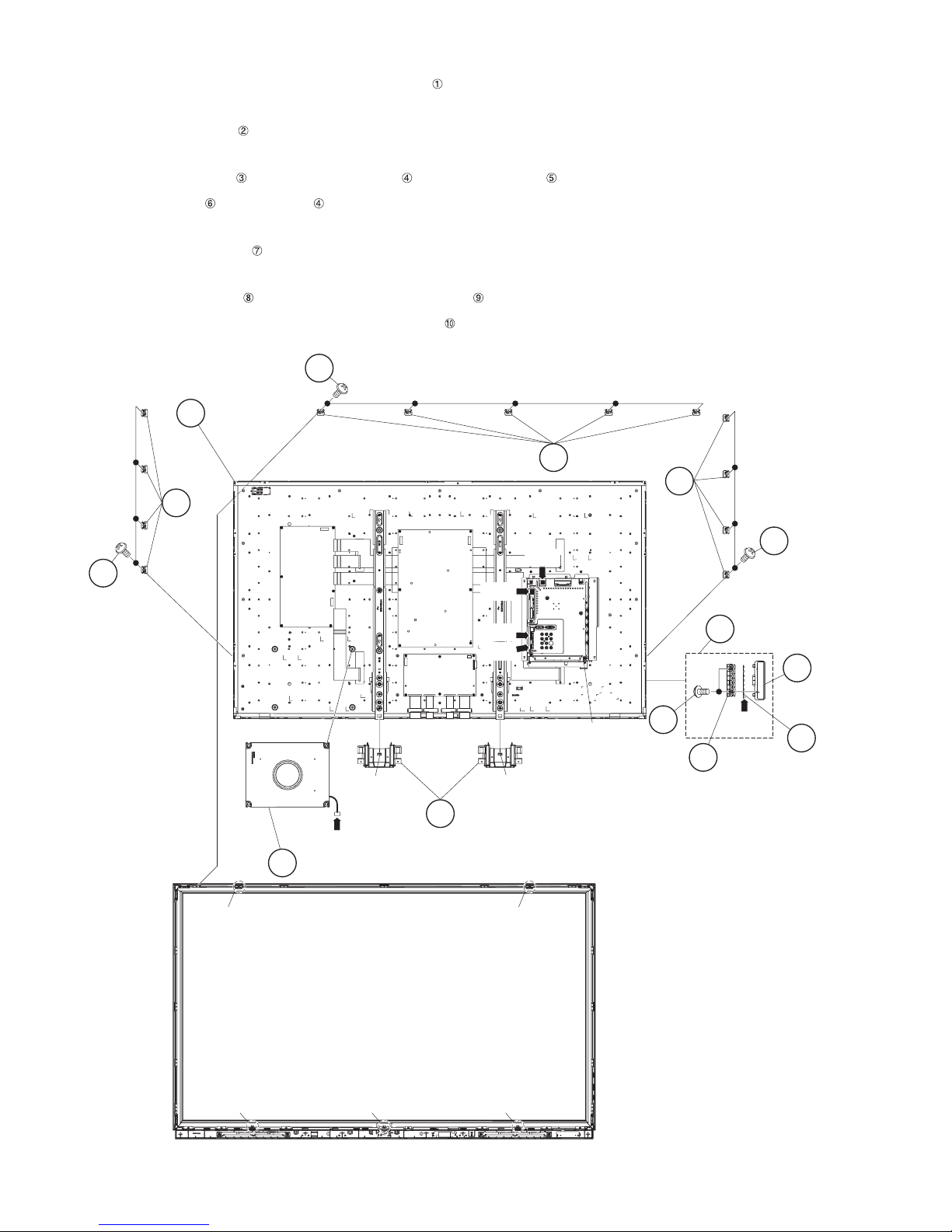
2. Removing of KEY Unit, Speaker (Woofer) and 60” LCD Panel Module Unit.
1. Remove the slide on 2 hooks and detach the 2 Bottom Covers .
2. Disconnect the RC wire.
3. Detach the KEY Unit Ass’y .
4. Disconnect the KM wire.
5. Remove the 2 lock screws and detach the Key Button from Key Button Cover .
6. Detach the KEY Unit from Key Button .
7. Disconnect the SB wire.
8. Detach the Speaker (Woofer) .
9. Disconnect the following connectors from the MAIN Unit. (SP, UB)
10.Remove the 13 lock screws and detach the 13 Fixing Metal Angles .
11.Remove the 5 hooks and detach the 60” LCD Panel Module Unit .
PRO-60/70X5FD
60" LCD Panel
Module Unit
10
9
Fixing
Metal
8
Angle
8
Fixing Metal Angle
Hook
[SB]
7 Speaker (Woofer)
[SB]
[SP]
[RC]
[UB]
Hook
1 Bottom Cover
9
MAIN Unit
9
Fixing
Metal
Angle
3
KEY Unit Ass'y
2
[KM]
4 Key
Button
8
Key
5
Button
Cover
6
KEY
Unit
Hook
Hook Hook Hook
Hook
4 – 2
Page 14
PRO-60/70X5FD
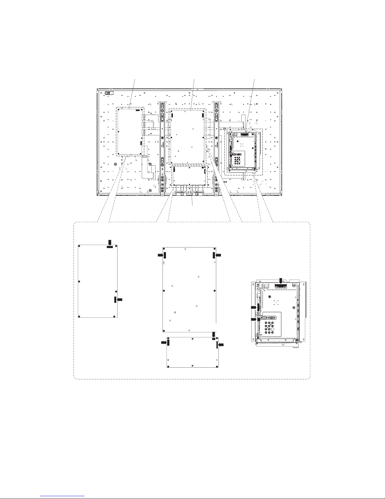
3. Removing of Connectors
1. Disconnect the following connectors from the MAIN Unit. (LW, PD, PL)
2. Disconnect the following connectors from the POWER Unit. (PD, LA)
3. Disconnect the following connectors from the LCD CONTROL Unit. (LB, LW, PL)
4. Disconnect the following connectors from the LED DRIVE Unit. (LA, LB)
LED DRIVE Unit
LED DRIVE Unit
[LA]
[LA]
POWER Unit
LCD CONTROL
Unit
POWER Unit
MAIN Unit
[PD]
MAIN Unit
[PD]
[LB]
[LB]
LCD CONTROL Unit
[LW]
[PL]
[PL]
[LW]
4 – 3
Page 15
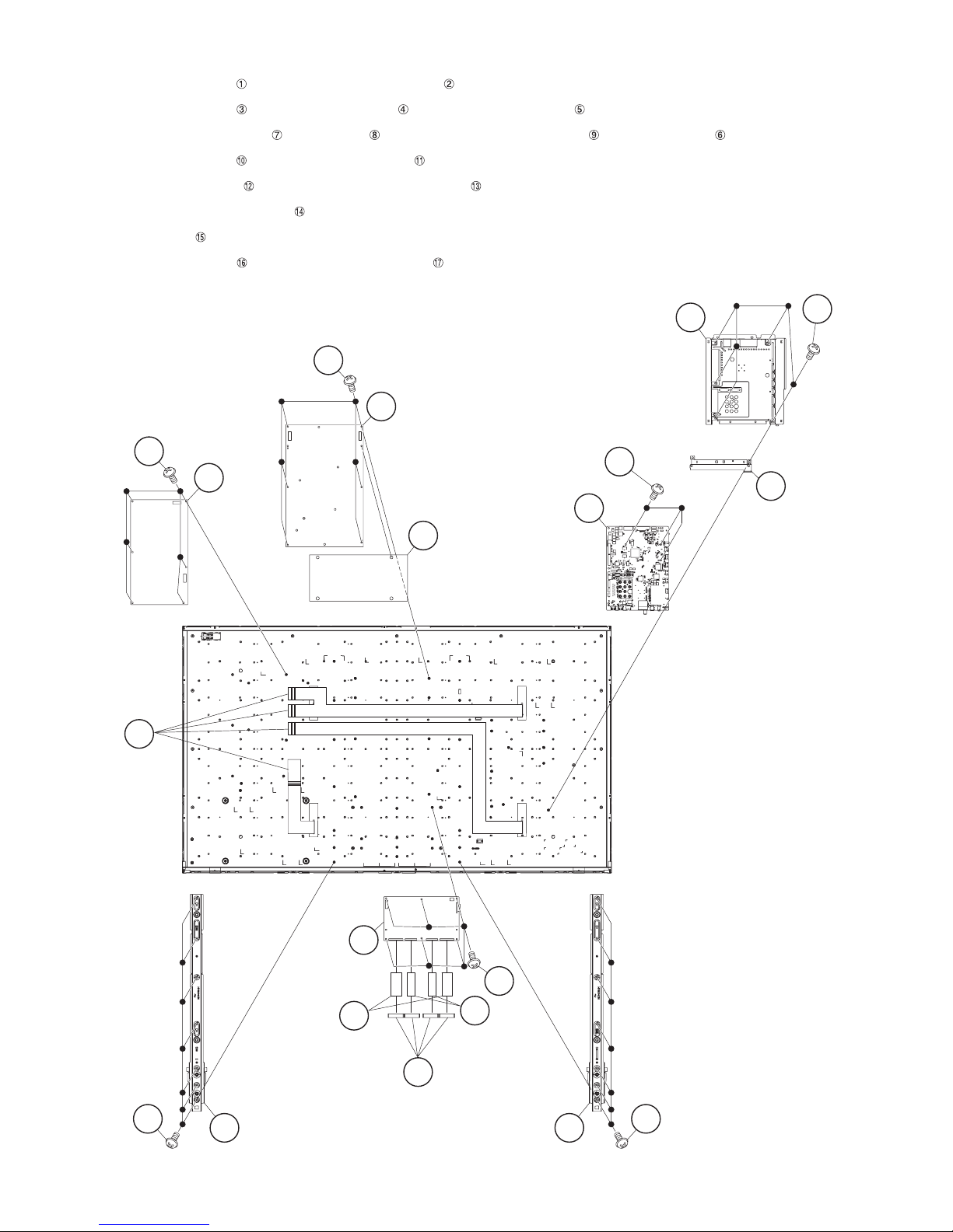
4. Removing of MAIN Unit, LCD CONTROL Unit, POWER Unit and LD DRIVE Unit.
1. Remove the 5 lock screws and detach the Shield (MAIN Unit) .
2. Remove the 3 lock screws and detach the MAIN Unit and Terminal Angle (Bottom) .
3. Remove the 4 Connecting Cords , 6 lock screws and detach the LCD CONTROL Unit and 4 Ferrite Cores .
4. Remove the 6 lock screws and detach the POWER Unit .
5. Remove the 14 lock screws and detach the 2 Center Angle Ass’ys .
6. Detach the POWER Insulation Sheet .
7. Detach the 4 FFCs .
8. Remove the 6 lock screws and detach the LED DRIVE Unit .
PRO-60/70X5FD
16
15
FFC
LED
DRIVE
Unit
17
10
11
POWER Unit
14
MAIN Unit
POWER
Insulation
Sheet
Shield (MAIN Unit)
3
4
2
1
5
Terminal
Angle
(Bottom)
LCD
CONTROL
Unit
FFC
(80Pin)
1312Center Angle
Ass'y
9
8
7
7
FFC
(64Pin)
6
Ferrite Core
Center Angle
13
12
Ass'y
4 – 4
Page 16
PRO-60/70X5FD
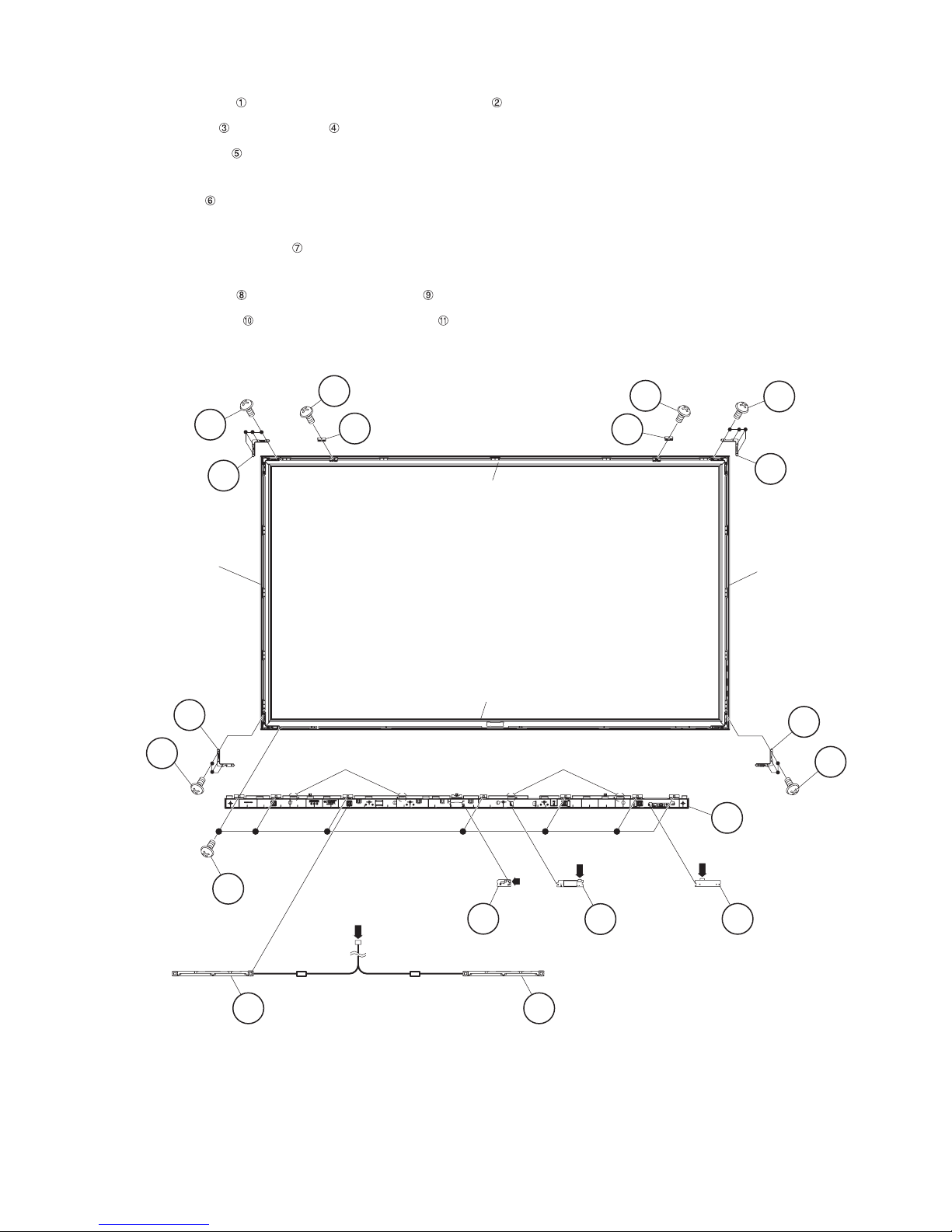
5. Removing of Speaker (L/R), 3D IR Emitter Unit, R/C OPC Unit, WiFi Unit and Decoration Frame (Top/Bottom/
L/R).
1. Remove the 7 lock screws , 4 hooks and detach the Bottom Body Ass’y .
2. Detach the Speaker (L) and Speaker (R) .
3. Detach the R/C OPC Unit .
4. Disconnect the RA wire.
5. Detach the WiFi Unit .
6. Disconnect the UB wire.
7. Disconnect the 3D IR EMITTER Unit .
8. Disconnect the IR wire.
9. Remove the 2 lock screws and detach the 2 Fixing Hooks .
10.Remove the 14 lock screws and detach the 4 Corner Angles .
11.Remove the Decoration Frame (Top/Bottom/L/R).
Corner Angle
Decoration
Frame (R)
Corner Angle
11
10
10
11
8
9
Fixing Hook Fixing Hook
Decoration Frame (Top)
Decoration Frame Ass'y (Bottom)
Hook Hook
[UB]
8
10
9
Corner
11
Angle
Decoration
Frame (L)
Corner Angle
11
10
2
Bottom Body
[RA]
Ass'y
41Speaker (R) 3 Speaker (L)
[SP]
3D IR
EMITTER
Unit
7
4 – 5
[IR]
6 WiFi
Unit
5 R/C OPC
Unit
Page 17
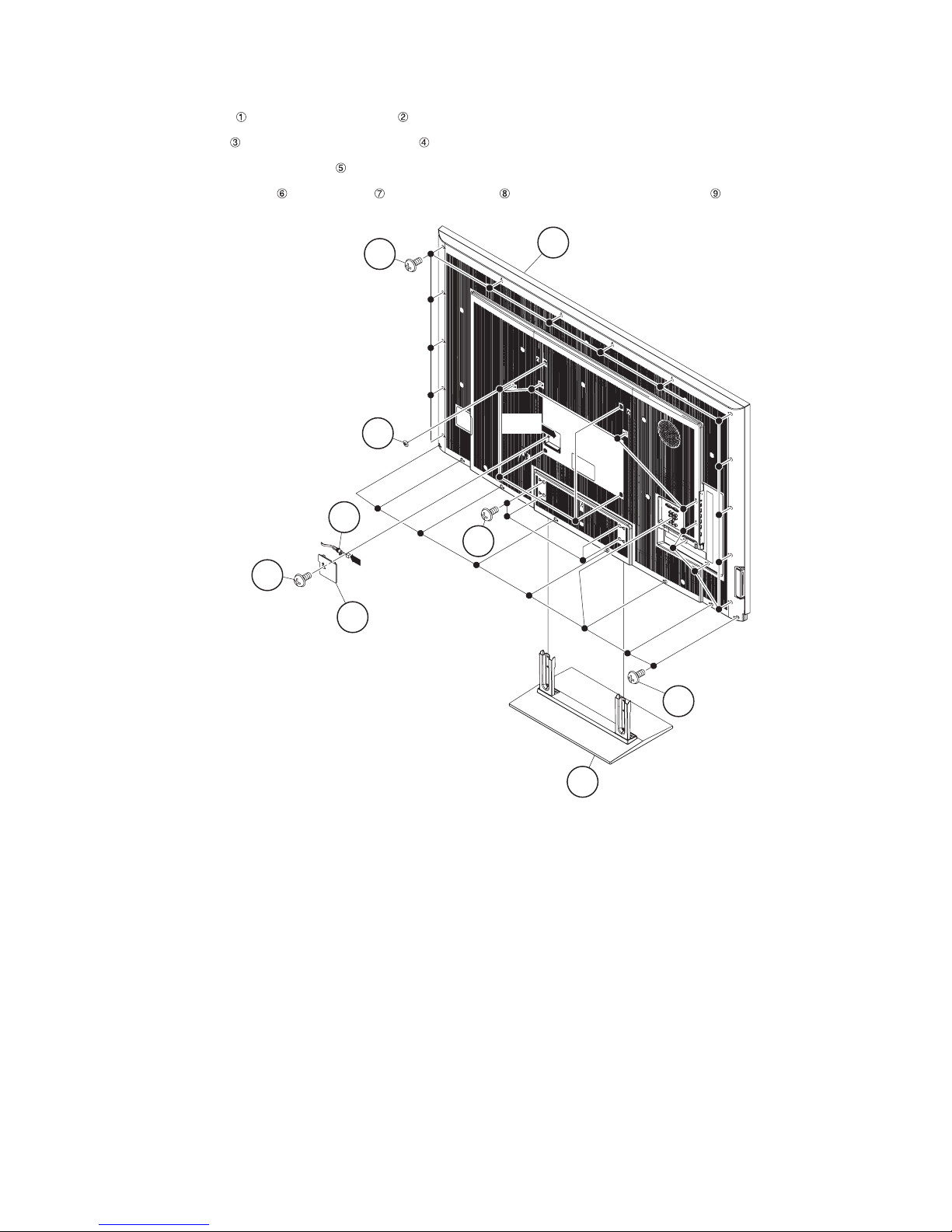
[2] REMOVING OF MAJOR PARTS (PRO-70X5FD)
1. Removing of Stand Unit and Rear Cabinet Ass’y.
1. Remove the 4 lock screws and detach the Stand Unit .
2. Remove the 1 lock screw and detach the AC Cord Cover .
3. Disconnect AC wire and detach the AC Cord .
4. Remove the 4 VESA Hole Covers , 9 lock screws and 21 lock screws and detach the Rear Cabinet Ass’y .
Rear Cabinet Ass'y
8
9
PRO-60/70X5FD
VESA Hole Cover
AC Cord
3
AC Cord Cover
5
4
6
[AC]
[AC]
1
7
2Stand Unit
4 – 6
Page 18
PRO-60/70X5FD
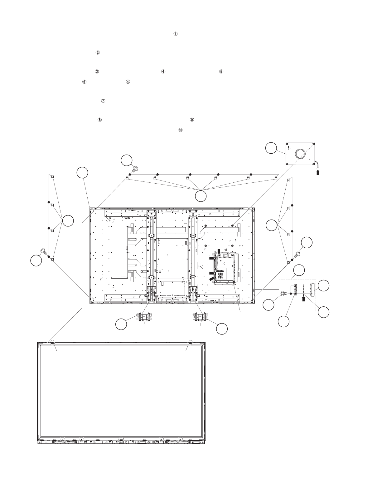
2. Removing of KEY Unit, Speaker (Woofer) and 70” LCD Panel Module Unit.
1. Remove the slide on 2 hooks and detach the 2 Bottom Covers .
2. Disconnect the RC wire.
3. Detach the KEY Unit Ass’y .
4. Disconnect the KM wire.
5. Remove the 2 lock screws and detach the Key Button from Key Button Cover .
6. Detach the KEY Unit from Key Button .
7. Disconnect the SB wire.
8. Detach the Speaker (Woofer) .
9. Disconnect the following connectors from the MAIN Unit. (SP, UB)
10.Remove the 14 lock screws and detach the 14 Fixing Metal Angles .
11.Remove the 2 hooks and detach the 70” LCD Panel Module Unit .
70" LCD Panel
Module Unit
Speaker (Woofer)
8
7
10
[SB]
Fixing Metal Angle
9
Fixing
Metal
Angle
8
9
[SP]
[RC]
[UB]
[SB]
9
Fixing
Metal
Angle
8
2
KEY Unit Ass'y
5
Key
Button
6
Cover
KEY
Unit
Bottom
Cover
3
[KM]
MAIN Unit
1
Hook
Hook
1
Bottom
4 Key
Button
Cover
Hook Hook
4 – 7
Page 19
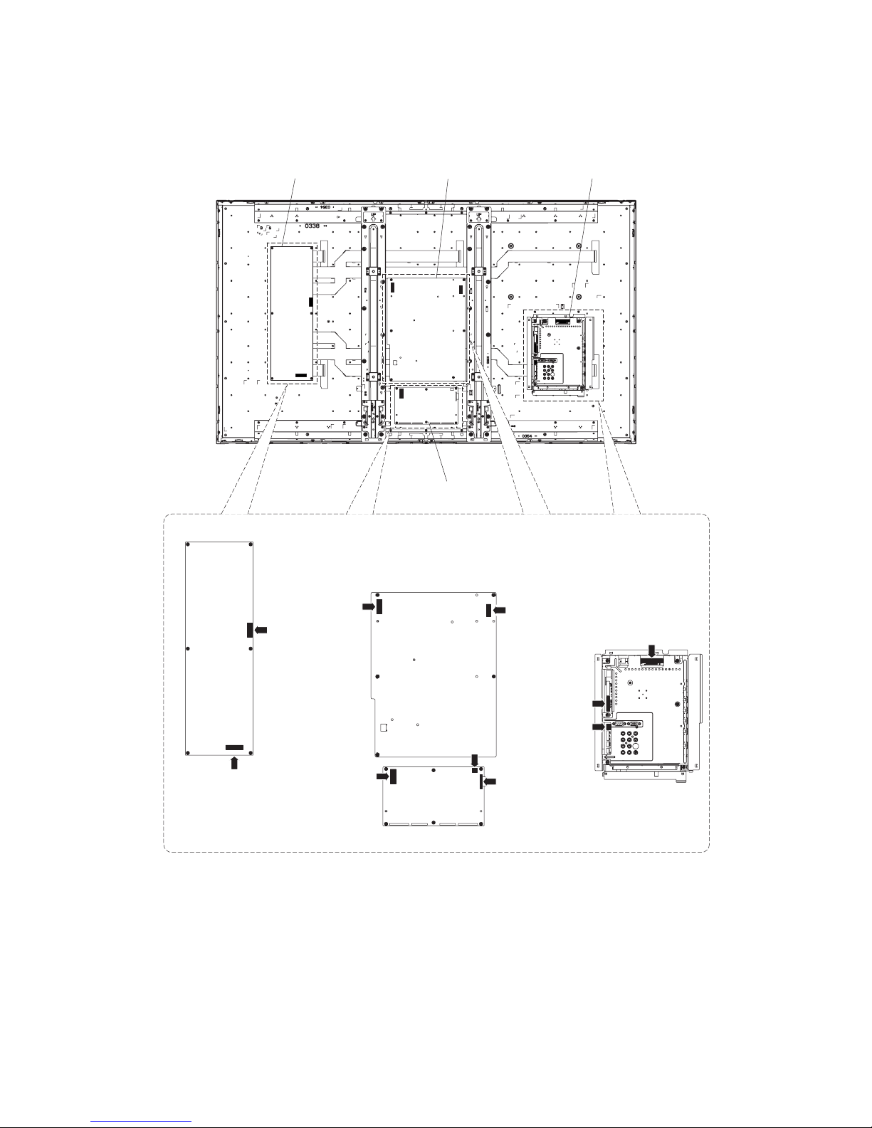
3. Removing of Connectors
1. Disconnect the following connectors from the MAIN Unit. (LW, PD, PL)
2. Disconnect the following connectors from the POWER Unit. (PD, LA)
3. Disconnect the following connectors from the LCD CONTROL Unit. (LB, LW, PL)
4. Disconnect the following connectors from the LED DRIVE Unit. (LA, LB)
PRO-60/70X5FD
LED DRIVE Unit
LED DRIVE Unit
POWER Unit
LCD CONTROL Unit
POWER Unit
MAIN Unit
[LB]
[LA]
[LA]
[LB]
LCD CONTROL Unit
[PL]
[PD]
[LW]
MAIN Unit
[PD]
[LW]
[PL]
4 – 8
Page 20
PRO-60/70X5FD
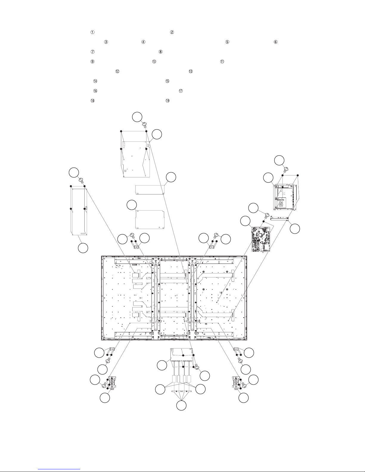
4. Removing of LCD CONTROL Unit, POWER Unit, MAIN Unit and LD DRIVE Unit.
1. Remove the 5 lock screws and detach the Shield (MAIN Unit) .
2. Remove the 4 Connecting Cords , 6 lock screws and detach the LCD CONTROL Unit and 4 Ferrite Cores .
3. Remove the 6 lock screws and detach the POWER Unit .
4. Remove the 2 lock screws and detach the MAIN Unit and Terminal Angle (Bottom) .
5. Detach the Power Insulation Sheet (L) and Power Insulation Sheet (S) .
6. Remove the 12 lock screws and detach the 2 Stand Angles .
7. Remove the 16 lock screws and detach the 4 VESA Angle Ass’ys .
8. Remove the 6 lock screws and detach the LED DRIVE Unit .
7
POWER Unit
8
1
18
LED DRIVE
Unit
19
POWER
Insulation
Sheet (L)
16
12
17
VESA
Angle
Ass'y
POWER
13
Insulation
Sheet (S)
VESA
Angle
Ass'y
17
(MAIN Unit)
MAIN Unit
16
Shield
10
2
9
11
Terminal
Angle (Bottom)
VESA Angle
17
Ass'y
16
14
15
LCD
CONTROL
Unit
FFC
(80pin)
VESA Angle Ass'y
17
5
4
3
3
FFC
(64pin)
15
16
14
Stand AngleStand Angle
6
Ferrite
Core
4 – 9
Page 21
PRO-60/70X5FD
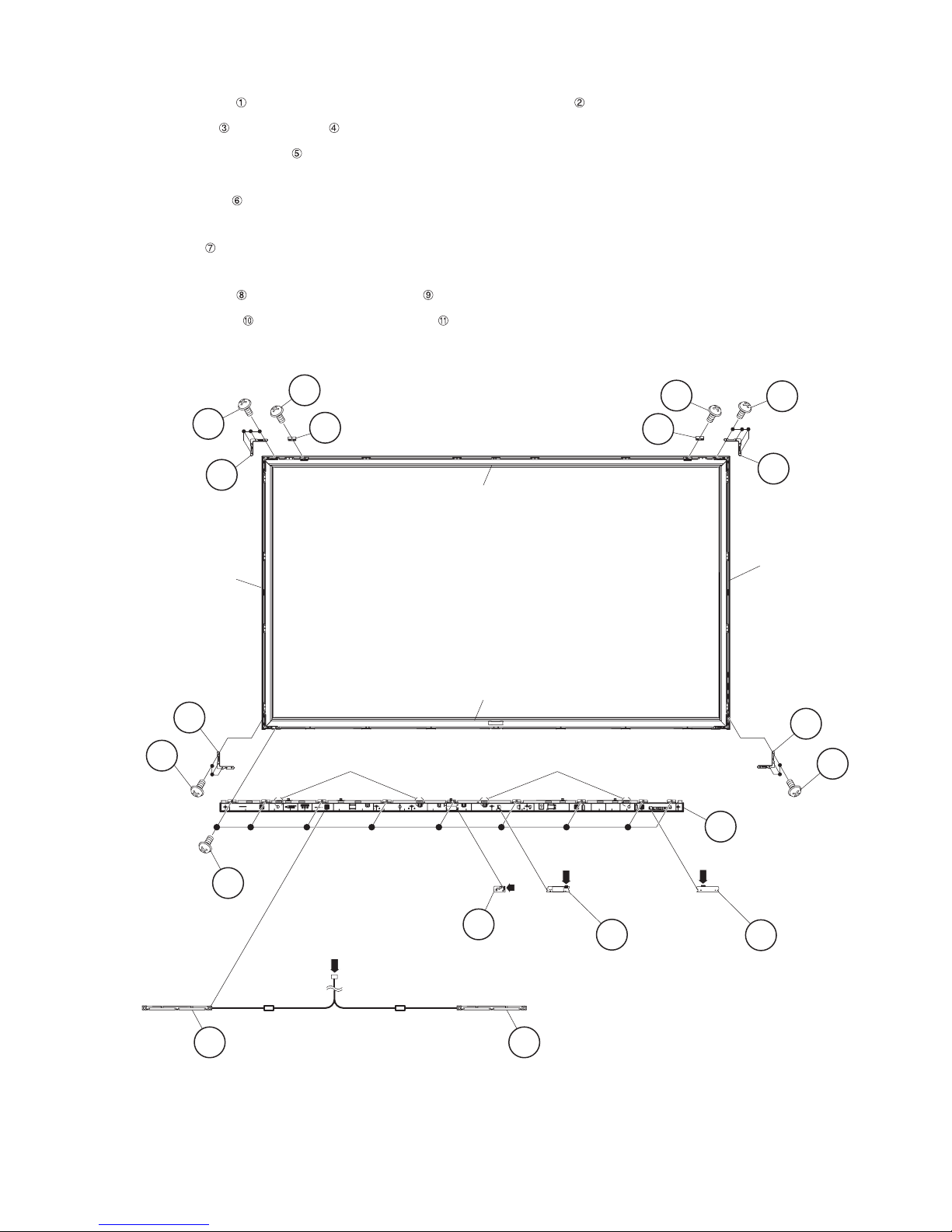
5. Removing of Speaker (L/R), 3D IR Emitter Unit, R/C OPC Unit, WiFi Unit and Decoration Frame (Top/Bottom/
L/R).
1. Remove the 9 lock screws , 4 hooks and detach the Decoration Frame Ass’y (Bottom) .
2. Detach the Speaker (L) and Speaker (R) .
3. Disconnect the 3D IR EMITTER Unit .
4. Disconnect the IR wire.
5. Detach the R/C OPC Unit .
6. Disconnect the RA wire.
7. Detach the WiFi Unit .
8. Disconnect the UB wire.
9. Remove the 2 lock screws and detach the 2 Fixing Hooks .
10.Remove the 14 lock screws and detach the 4 Corner Angles .
11.Remove the Decoration Frame (Top/Bottom/L/R).
Corner Angle
Decoration
Frame (R)
Corner Angle
11
10
10
11
8
9
Fixing Hook
Decoration Frame (Top)
Decoration Frame Ass'y (Bottom)
Hook Hook
Fixing Hook
[UB]
8
10
9
11
Corner
Angle
Decoration
Frame (L)
Corner Angle
11
10
2
Bottom Body
[RA]
Ass'y
[SP]
41Speaker (R) 3 Speaker (L)
[IR]
5
3D IR
EMITTER Unit
4 – 10
7 WiFi Unit
6
R/C OPC
Unit
Page 22
PRO-60/70X5FD
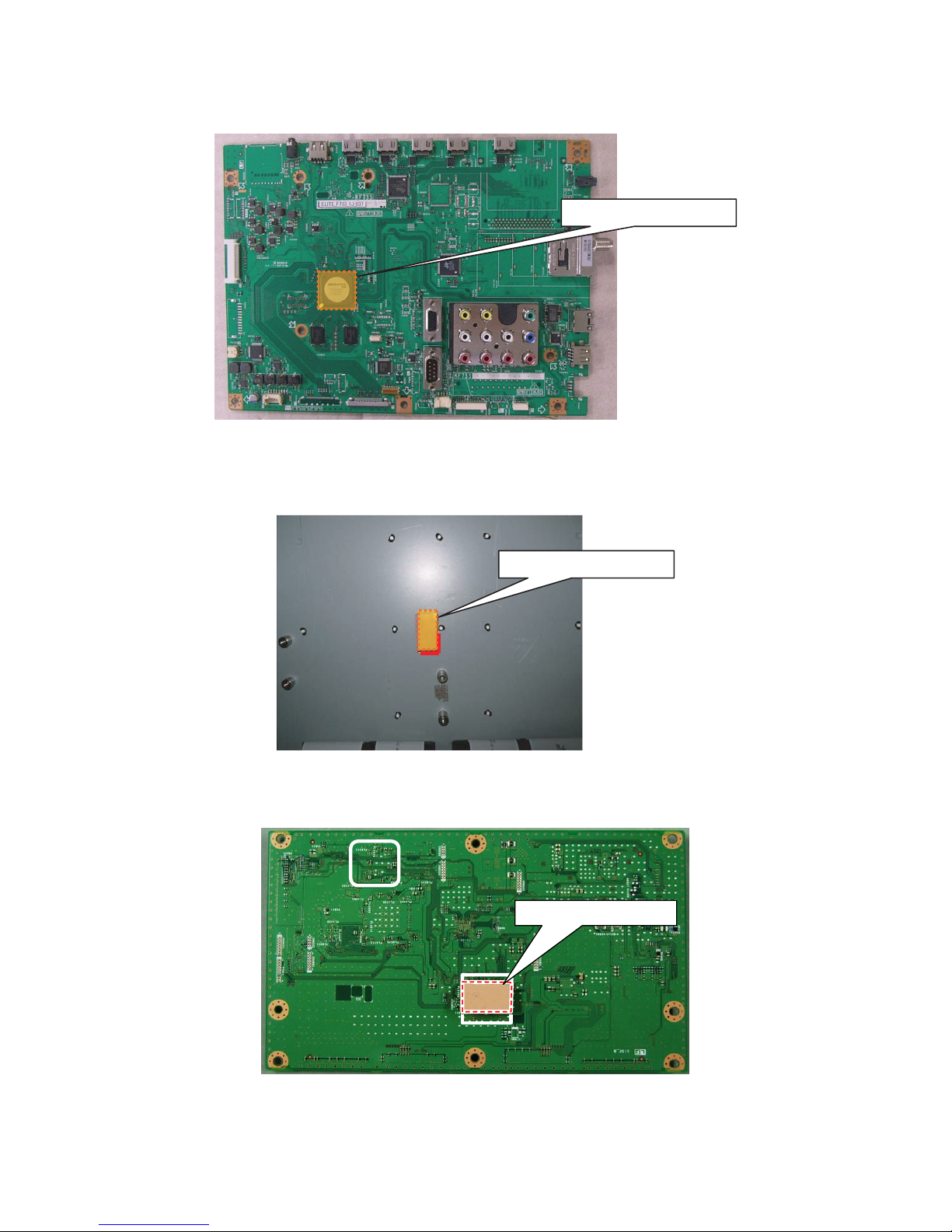
[3] The location putting on the heat measure sheet
1. MAIN PWB Unit
2. LCD Control Unit
(PRO-60X5FD)
PSPAZC741WJKZ
(PRO-70X5FD)
PSPAZC782WJKZ
PSPAZC782WJKZ
4 – 11
Page 23
PRO-60/70X5FD
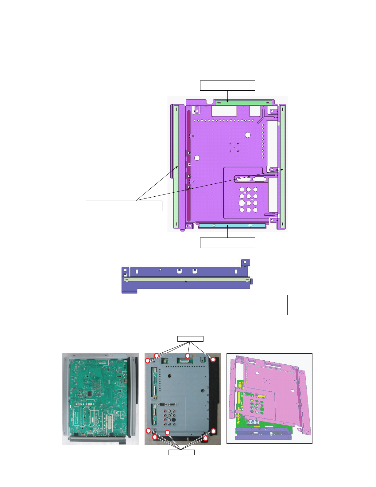
[4] Precautions for assembly
1. Points to be checked and precautions when servicing the unit
Mount the main PWB Ass’y on the backlight chassis and check that the EMI-prevention parts are not peeled and twisted from the access holes. (The
EMI-prevention parts, conductive nonwoven fabric gaskets, must be seen from the access holes.)
[Countermeasure]
Attach the conductive nonwoven fabric gaskets on the shielded case on the main PWB.
PMLT-A679WJQZ
PMLT-A678WJQZx2pcs
Attach the conductive nonwoven fabric gasket on the RF terminal angle.
(PMLT-A680WJQZ)
State where the main PWB and shielded case are assembled
PSPAZC740WJZZ
Access hole
Access hole
4 – 12
Page 24
PRO-60/70X5FD
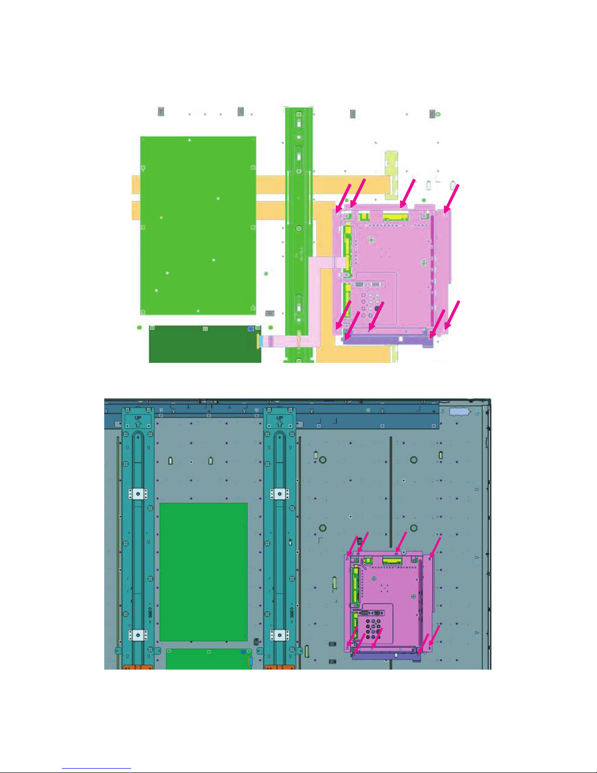
The following is a drawing mounting the main PWB Ass’y on the backlight chassis. (The parts indicated by -> are the access holes for confirmation.)
(Main PWB Ass’y => State where the shielded case and RF terminal angle are mounted on the main PWB)
(PRO-60X5FD)
(PRO-70X5FD)
4 – 13
Page 25
PRO-60/70X5FD
[5] The way of detaching Rear Cabinet Ass'y
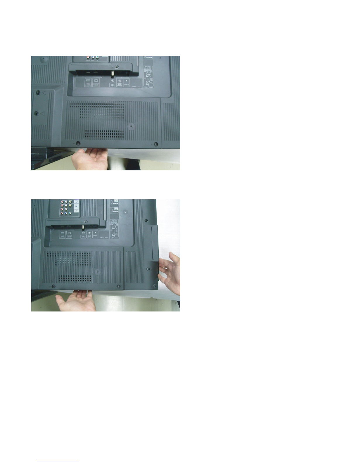
• Here are the way of detaching Rear Cabinet Ass’y. Please respond in following order.
1. Lay the TV set down on the desk or table with the glass side down, set the left hand between Decoration Frame and Rear Cabinet Ass’y on the
bottom of right corner side.
2. Set the right hand between Decoration Frame and Rear Cabinet Ass’y on the right side in the under corner.
4 – 14
Page 26
PRO-60/70X5FD
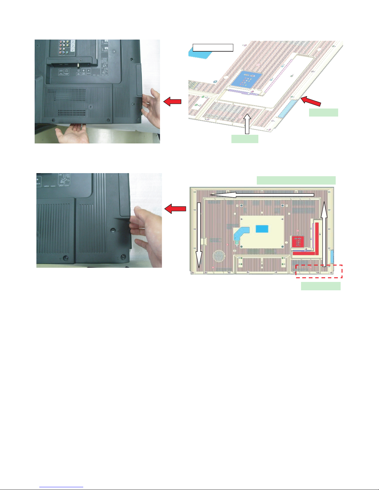
3. Push Rear Cabinet Ass’y toward the center of TV set with right hand. At the same time, open Rear Cabinet Ass’y in the back side with left hand
and detach the hook.
Figure for image
Right Hand
Left Hand
4. Detach the hooks one by one in a counterclockwise direction with changing the position of right hand.
Follow the arrows for removing
Start Position
4 – 15
Page 27

PRO-60/70X5FD
PRO60X5FD
CHAPTER 5. ADJUSTMENT
Service Manual
[1] ADJUSTMENT PROCEDURE
The adjustment values are set to the optimum conditions at the factory before shipping. If a value should become improper or an adjustment is
required due to part replacement, make an adjustment according to the following procedure.
1. After replacement of any PWB unit and/or IC for repair, please note the following.
• When replacing the following units, make sure to prepare the new units loaded with updated software.
MAIN Unit: DKEYMF733FM21: PRO-60X5FD
DKEYMF733FM20: PRO-70X5FD
• When replacing the LCD control PWB, perform the VCOM adjustment.
2. Upgrading of each microprocessor software
CAUTION: Never “POWER OFF” the unit when software upgrade is ongoing.
Otherwise the system may be damaged beyond recovery.
2.1. Software version upgrade
The model employs the following software.
• Main software PRO-60/70X5FD (please use a software version after BSMK_X5FD_xxx.USB).
• Monitor microprocessor software (please use a software version BSMK_X5FD_xxx.USB and BMELMxxx.SMB.)
The main software, monitor microprocessor software can be upgraded by using a general-purpose USB Memory.
The followings are the procedures for upgrading, explained separately for the main software, monitor microprocessor software.
2.2. Main software version upgrade
2.2.1 Get ready before you start
• USB Memory of 128MB or higher capacity.
• PC running on Windows 98/98SE/ME/2000/XP operating system.
• USB Memory reader/writer or PC with a USB port.
• The file system of a USB memory is FAT. (FAT32 supports)
• Use the USB memory without other functions. (lock and memory reader...etc)
2.2.2 Preparations
To upgrade the main software, it is necessary to get ready the USB Memory for version upgrade before you start.
Follow the steps below and create the USB Memory for version upgrade.
1. Copy the file BSMK_X5FD_xxx.USB for version upgrade to the root directory (folder) of the USB Memory.
NOTE: In the USB Memory drive, do not store other folders or unrelated files, or more than one file for version upgrade.
Now the USB Memory for version upgrade is ready.
5 – 1
Page 28

PRO-60/70X5FD
2.2.3 How to upgrade the software
1. Unplug the AC cord.
2. Insert the USB Memory for version upgrade into the service socket.
3. Plug in the AC cord with power button pressed down.
4. After 5 seconds, unpress the power button.
5. After the unit startup, the system upgrade screen as shown below within 20-40 seconds.
Software Update
MAIN Version
SUB MICOM Version
PANEL EEPROM
3D IR MICOM Version
MAIN
SUB MICOM
PANEL EEPROM
3D IR MICOM
26%
SAME VERSION
NO DATA
104U1107111
70X5FD
6. Even a single failure in the process will trigger the upgrade failure screen.
Software Update
MAIN Version
SUB MICOM Version
PANEL EEPROM
3D IR MICOM Version
UPGRADE FAILURE
MAIN
SUB MICOM
PANEL EEPROM
3D IR MICOM
Project ID
NO DATA
NO DATA
OK
1.00
70X5FD
NOTE: In the event of a failure, repeat the upgrade process. If the process repeatedly fails, it is likely that the hardware need fixing.
7. Upon completion of the whole process, the upgrade success screen as shown below appears. You can check the new software version on this
screen. The version information appears after the upgrade is complete.
Software Update
MAIN Version
SUB MICOM Version
PANEL EEPROM
3D IR MICOM Version
UPGRADE SUCCESS
MAIN
SUB MICOM
PANEL EEPROM
3D IR MICOM
100%
NO DATA
NO DATA
OK
U1007071
1.00
70X5FD
8. Unplug the AC cord and remove the USB Memory for version upgrade.
9. Now the software version upgrade is complete.
NOTE: When you are done with the software version upgrade, start the set, go to the top page of the adjustment process screen and check the main
software version information.
5 – 2
Page 29

PRO-60/70X5FD
2.3. Monitor microprocessor software version upgrade
Create the USB memory for monitor microprocessor software version upgrade in the same manner as explained in the “Main software version
upgrade”.
Copy the file BSMK_X5FD_xxx.USB and BMELMxxx.SMB. (named temporarily) for monitor microprocessor software version upgrade to the USB
memory.
2.3.1 How to upgrade the software
1. Unplug the AC cord.
2. Insert the USB Memory for version upgrade into the service socket.
3. Plug in the AC cord with power button pressed down.
4. After 5 seconds, unpress the power button.
CAUTION: • The moment this operation is done, the upgrading of the monitor microprocessor software starts. While the upgrade is ongoing, never
5. After the unit startup, the upgrade starts. The power led will blink continuously. Also, an upgrade screen will be shown during a minor upgrade.
power off the unit. Otherwise the upgrade will fail and the system may be serious damaged beyond recovery (inability to start).
• After the monitor microprocessor software is upgraded, also perform the ‘Industry Init’.
Software Update
MAIN Version
SUB MICOM Version
PANEL EEPROM
3D IR MICOM Version
MAIN
SUB MICOM
PANEL EEPROM
3D IR MICOM
NO DATA
50%
NO DATA
OK
0.820
1.00
70X5FD
6. If the upgrade fails, power led will stop blinking. Also, the upgrade failure screen will be shown if upgrade screen was shown at 5.
Software Update
MAIN Version
SUB MICOM Version
PANEL EEPROM
3D IR MICOM Version
UPGRADE FAILURE
MAIN
SUB MICOM
PANEL EEPROM
3D IR MICOM
NO DATA
SAME VERSION
NO DATA
OK
1.00
70X5FD
NOTE: In the event of a transient failure, upgrade will be automatically retried up to three times. If the process repeatedly fails, hardware may be the
cause.
7. The upgrade success screen will be shown if upgrade screen was shown at 5.
8. Unplug the AC cord and remove the USB Memory for version upgrade.
9. Now the software version upgrade is complete.
NOTE: When you are done with the software version upgrade, start the set, go to the top page of the adjustment process screen and check the mon-
itor microprocessor software version information and panel size information.
Software Update
MAIN Version
SUB MICOM Version
PANEL EEPROM
3D IR MICOM Version
5 – 3
UPGRADE SUCCESS
MAIN
SUB MICOM
PANEL EEPROM
3D IR MICOM
70XF5D
100%
SAME VERSION
NO DATA
104U1107111
Page 30
PRO-60/70X5FD
3. Entering and exiting the adjustment process mode
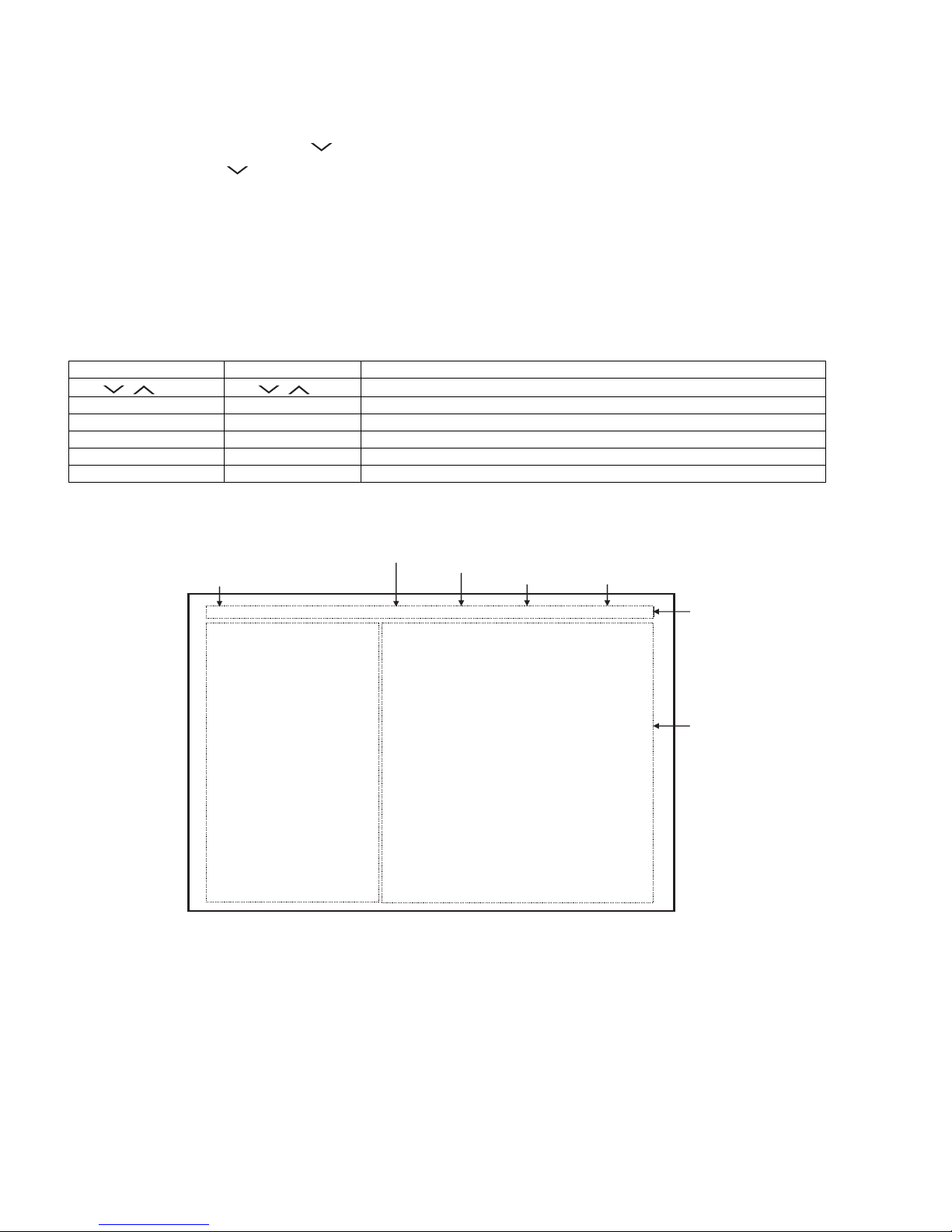
1) Before entering the adjustment process mode, the AV position RESET in the video adjustment menu.
2) While holding down the “VOL (–)” and “INPUT” keys at a time, plug in the AC cord of the main unit to turn on the power.
The letter “<K>” appears on the screen.
3) Next, hold down the “VOL (–)” and “CH ( )” keys at a time.
(The “VOL (–)” and “CH ( )” keys should be pressed and held until the display appears.)
Multiple lines of blue characters appearing on the display indicate that the unit is now in the adjustment process mode.
When you fail to enter the adjustment process mode (the display is the same as normal startup), retry the procedure.
4) To exit the adjustment process mode after the adjustment is done, unplug the AC cord from the outlet to make a forced shutdown. (When the
power was turned off with the remote controller, once unplug the AC cord and plug it again. In this case, wait 10 seconds or so before plugging.)
CAUTION: Use due care in handling the information described here lest your users should know how to enter the adjustment process mode. If the
4. Remote controller key operation and description of display in adjustment process mode
1) Key operation
Remote controller key Main unit key Function
CH ( / ) CH ( / )
VOL (+/–) VOL (+/–) Changing a selected item setting (+1/ –1)
Cursor (UP/DOWN) ————— Turing a page (PREVIOUS/NEXT)
Cursor (LEFT/RIGHT) ————— Changing a selected line setting (+10/ –10)
INPUT ————— Input switching (toggle switching)
ENTER ————— Executing a function
2) Description of display
settings are tampered in this mode, unrecoverable system damage may result.
Moving an item (line) by one (UP/DOWN)
*Input mode is switched automatically when relevant adjustment is started so far as the necessary input signal is available.
(1) Current page/
Total pages
1/29 INPUT AUTO USA 60_UNDER
MAIN Version
BOOT Version
Monitor / Monitor BOOTVersion
T-CON Version / LED CON Version
NETFLIX ESN
WIDEVINE DEVICE ID
FRC Version
TOUCH SENSOR/IR Micom Version
TEMPERATURE 5C
LAMP ERROR
MONITOR ERR CAUSE
NORMAL STANDBY CAUSE
ERROR STANDBY CAUSE
(2) Current selected input
(3) Current color system
1.04 (U 2011/07/11 1 A)
BSMKxxx
1.02 / 1.01
20110127DA6000800(ROHM)/60df00000000
SH-TVX5PRO0000CD13
LCDTV6879ED75F6DF
2.0a_1.10.3 / 2.1b_2.01
0000 / ---
0
1) 11 B00000103:18 2) 11 B00000102:13
3) 1A B00000066:46 4) 11 B00000058:34
0
00000
(4) Destination
(5) LCD Panel size/Speaker type
(6) Adjustment
process menu
header
(7) Parameters
5 – 4
Page 31
PRO-60/70X5FD
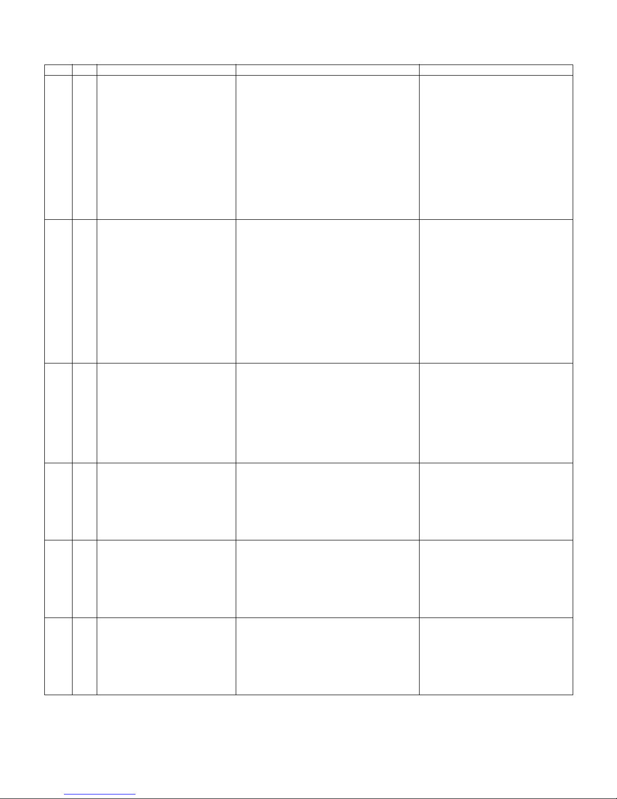
5. List of adjustment process mode menu
The character string in brackets [ ] will appear as a page title in the adjustment process menu header.
Page Line Item Description Remarks (adjustment detail, etc.)
1 1 MAIN Version Main software version
2BOOT Version
3 Monitor / Monitor BOOT Version Monitor and monitor boot software version
4 T-CON Version / LED CON Version LCD controller software version
5 NETFLIX ESN
6 WIDEVINE DEVICE ID
7 FRC Version
8 TOUCH SENSOR/IR Micom Version
9 TEMPERATURE Panel temperature
10 LAMP ERROR Number of termination due to lamp error
11 MONITOR ERR CAUSE
12 NORMAL STANDBY CAUSE Refer to *1 under the list for details
13 ERROR STANDBY CAUSE Refer to *2 under the list for details
2 1 INDUSTRY INIT Initialization to factory settings
2 INDUSTRY INIT(-Public)
3 PUBLIC MODE Public mode
4 Center Acutime Accumulated main operation time
5 RESET Reset
6 Backlight Acutime Accumulated monitor operation time
7 RESET Reset
8 LAMP ERROR RESET Reset LAMP ERROR
9 VIC XPOS X-coordinate setting for VIC READ
10 VIC YPOS Y-coordinate setting for VIC READ
11 VIC COLOR Collected color data setting for VIC READ
12 VIC SIGNAL TYPE Signal type setting for VIC READ
13 VIC READ Picture level acquisition function Level appears in green on the upper right
3 1 N358 ALL ADJ(INPUT2) CVBS and TUNER signal level adjustment
2 N358 MAIN ADJ(INPUT2) CVBS signal level adjustment
3 TUNER DAC ADJ TUNER signal level adjustment
4 N358 CONTRAST A_GAIN
5 N358 CONTRAST D_GAIN
6 N358 CONTRAST OFFSET
7 TUNER CONTRAST A_GAIN
8 TUNER CONTRAST D_GAIN
9 TUNER CONTRAST OFFSET
4 1 TUNER VCHIP TEST(69ch) Tuning test and VCHIP test (69ch)
2 TUNER VCHIP TEST(7ch) Tuning test and VCHIP test (7ch)
3 TUNER VCHIP TEST(10ch) Tuning test and VCHIP test (10ch)
4 TUNER VCHIP TEST(15ch) Tuning test and VCHIP test (15ch)
5 INSPECT USB TERM
6 HDMI EDID WRITE
7 HDMI CEC TEST
5 1 COMP15K ADJ(INPUT1) Component 15K picture level adjustment (main)
2 COMP15K Y A_GAIN
3 COMP15K Cb A_GAIN
4 COMP15K Cr A_GAIN
5 COMP15K Y OFFSET
6 COMP15K Cb OFFSET
7 COMP15K Cr OFFSET
6 1 COMP33K ADJ(INPUT1) Component 33K picture level adjustment (main)
2 COMP33K Y A_GAIN
3 COMP33K Cb A_GAIN
4 COMP33K Cr A_GAIN
5 COMP33K Y OFFSET
6 COMP33K Cb OFFSET
7 COMP33K Cr OFFSET
5 – 5
Page 32
PRO-60/70X5FD
Page Line Item Description Remarks (adjustment detail, etc.)
7 1 ANALOG RGB ADJ Analog RGB picture level adjustment
2 R A_GAIN
3 G A_GAIN
4 B A_GAIN
5 R OFFSET
6 G OFFSET
7 B OFFSET
8 1 VCOM ADJ VCOM adjustment value
9 1 LEV1 Standard value 1 Adjustment gradation setting.
2 LEV2 Standard value 2
3 LEV3 Standard value 3
4 LEV4 Standard value 4
5 LEV5 Standard value 5
6 LEV6 Standard value 6
10 1 MG1R WB adjustment Point 1, R adjustment value Parameter for six-point adjustment
2 MG1G WB adjustment Point 1, G adjustment value
3 MG1B WB adjustment Point 1, B adjustment value
4 MG1Y WB adjustment Point 1, Y adjustment value
5 MG2R WB adjustment Point 2, R adjustment value
6 MG2G WB adjustment Point 2, G adjustment value
7 MG2B WB adjustment Point 2, B adjustment value
8 MG2Y WB adjustment Point 2, Y adjustment value
9 MG3R WB adjustment Point 3, R adjustment value
10 MG3G WB adjustment Point 3, G adjustment value
11 MG3B WB adjustment Point 3, B adjustment value
12 MG3Y WB adjustment Point 3, Y adjustment value
11 1 MG4R WB adjustment Point 4, R adjustment value Parameter for six-point adjustment
2 MG4G WB adjustment Point 4, G adjustment value
3 MG4B WB adjustment Point 4, B adjustment value
4 MG4Y WB adjustment Point 4, Y adjustment value
5 MG5R WB adjustment Point 5, R adjustment value
6 MG5G WB adjustment Point 5, G adjustment value
7 MG5B WB adjustment Point 5, B adjustment value
8 MG5Y WB adjustment Point 5, Y adjustment value
9 MG6R WB adjustment Point 6, R adjustment value
10 MG6G WB adjustment Point 6, G adjustment value
11 MG6B WB adjustment Point 6, B adjustment value
12 MG6Y WB adjustment Point 6, Y adjustment value
13 MG6Y OFFSET
12 1 LO R 1 WB adjustment Point 1, R adjustment value
2 LO G 1 WB adjustment Point 1, G adjustment value
3 LO B 1 WB adjustment Point 1, B adjustment value
4 LO Y 1 WB adjustment Point 1, Y adjustment value
5 LO R 2 WB adjustment Point 2, R adjustment value
6 LO G 2 WB adjustment Point 2, G adjustment value
7 LO B 2 WB adjustment Point 2, B adjustment value
8 LO Y 2 WB adjustment Point 2, Y adjustment value
9 LO R 3 WB adjustment Point 3, R adjustment value
10 LO G 3 WB adjustment Point 3, G adjustment value
11 LO B 3 WB adjustment Point 3, B adjustment value
12 LO Y 3 WB adjustment Point 3, Y adjustment value
13 1 LO R 4 WB adjustment Point 4, R adjustment value
2 LO G 4 WB adjustment Point 4, G adjustment value
3 LO B 4 WB adjustment Point 4, B adjustment value
4 LO Y 4 WB adjustment Point 4, Y adjustment value
5 LO R 5 WB adjustment Point 5, R adjustment value
6 LO G 5 WB adjustment Point 5, G adjustment value
7 LO B 5 WB adjustment Point 5, B adjustment value
8 LO Y 5 WB adjustment Point 5, Y adjustment value
9 LO R 6 WB adjustment Point 6, R adjustment value
10 LO G 6 WB adjustment Point 6, G adjustment value
11 LO B 6 WB adjustment Point 6, B adjustment value
12 LO Y 6 WB adjustment Point 6, Y adjustment value
13 CTEMP SELECT
5 – 6
Page 33
PRO-60/70X5FD
Page Line Item Description Remarks (adjustment detail, etc.)
14 1 MODE SELECT
2 POS SELECT
3POS MIN
4POS MID1
5POS MID2
6POS MID3
7POS MID4
8POS MID5
9POS MID6
10 POS MAX
15 1 CD MIN
2 CD MID1
3 CD MID2
4 CD MID3
5 CD MID4
6 CD MID5
7 CD MID6
8 CD MAX
16 1 CALC
2 RESET
3VAL1
4VAL2
5VAL3
6VAL4
7VAL5
8VAL6
9 GAMMA ADJ TEMP
17 1 MONITOR TIME OUT
2 MONITOR MAX TEMP
3 MONITOR ERROR CAUSE RESET
18 1 LCD TEST PATTERN
2 LCD TEST PATTERN1
3 LCD TEST PATTERN2
4 LCD TEST PATTERN3
5 LCD TEST PATTERN4
6 TV TEST PATTERN 1
7 TV TEST PATTERN 2
19 1 T-CON VERSION EXT.1 PRIMROSE 2D Version
2 T-CON VERSION EXT.2 PRIMROSE 3D Version
3 T-CON VERSION EXT.3 Blank (Not Use)
4 T-CON VERSION EXT.4 Blank (Not Use)
20 1 3D HDMI FPGA Version
2 2D->3D FPGA Version
3 3D IR EMITTER CONTROL
21 1 READ/WRITE
2 SLAVE ADDRESS
3 RESISTER ADDRESS UPPER
4 RESISTER ADDRESS LOWER
5 WRITE DATA UPPER
6WRITE DATA LOWER
7 READ DATA UPPER
8 READ DATA LOWER
22 1 POWER LED BRIGHTNESS
2 MENU LED BRIGHTNESS
3 INPUT LED BRIGHTNESS
4 CH UP LED BRIGHTNESS
5 CH DOWN LED BRIGHTNESS
6 VOL UP LED BRIGHTNESS
7 VOL DOWN LED BRIGHTNESS
8 LOGO LED BRIGHTNESS
9 ICON LED BRIGHTNESS
10 ICON LED BRIGHTNESS
(STANDBY)
11 3D LED BRIGHTNESS
5 – 7
Page 34
PRO-60/70X5FD
Page Line Item Description Remarks (adjustment detail, etc.)
23 1 POWER KEY SENSITIVITY
2 MENU KEY SENSITIVITY
3 INPUT KEY SENSITIVITY
4 CH UP KEY SENSITIVITY
5 CH DOWN KEY SENSITIVITY
6 VOL UP KEY SENSITIVITY
7 VOL DOWN KEY SENSITIVITY
24 1 KEY STRENGTH GET MODE
2 POWER KEY STRENGTH
3 MENU KEY STRENGTH
4 INPUT KEY STRENGTH
5 CH UP KEY STRENGTH
6 CH DOWN KEY STRENGTH
7 VOL UP KEY STRENGTH
8 VOL DOWN KEY STRENGTH
25 1 CROSSTALK ADJ MODE
2 CROSSTALK TH1
3 CROSSTALK TH2
4 CROSSTALK TH3
5 CROSSTALK TH4
6 CROSSTALK GAIN1
7 CROSSTALK GAIN2
8 CROSSTALK GAIN3
26 1 WIFI SSID 2.4 GHz Set AP SSID
2 WIFI SSID 5 GHz Set AP SSID
3 WIFI RSSI 2.4 GHz Set RSSI threshold
4 WIFI RSSI 5 GHz Set RSSI threshold
5 WIFI TIME 2.4 GHz Set Time Out
6 WIFI TIME 5 GHz Set Time Out
7 WIFI RSSI TEST Execute test
8 WIFI RSSI RESULT Display test result
27 1 KEY LOCK (1217)
2 KOUTEI AREA ALL CLEAR
3 A MODE AREA CLEAR
4 BACKUP AREA CLEAR
5 B MODE AREA CLEAR
6EXECUTION
28 1 ERROR STANDBY CAUSE1
2 ERROR STANDBY CAUSE2
3 ERROR STANDBY CAUSE3
4 ERROR STANDBY CAUSE4
5 ERROR STANDBY CAUSE5
6 ERROR STANDBY CAUSE RESET
29 1 EEP SAVE Writing setting values to EEPROM
2 EEP RECOVER Reading setting values from EEPROM
3MODEL NAME
4 PANEL SIZE
5 SETTING FOR ADJ
6 VERUP FLAG ENABLE
7 SHARP RC ENABLE
8 PANEL LIMIT
9 PANEL RANGE LIMIT
10 SHORT CHECK MODE
11 SHORT CHECK CURRENT
12 CURRENT SW
13 TEST NETWORK UPDATE
5 – 8
Page 35
PRO-60/70X5FD
*1 Details of P1.12 (NORMAL STANDBY CAUSE)
When TV set is powered off due to normal use or product specification, the last cause will be recorded.
The code, character string and description for the standby cause are below.
If you power off by remote, the cause will not be recorded.
Code Character string Description
2 NO_OPERT No operation off
3 NO_SIGNA No signal off
6 SLEEP_TM Off timer
8 OFF_232C Command from RS232C
*2 Details of P1.13 (ERROR STANDBY CAUSE)
When TV set is powered off due to any anomaly detection, the past 5 causes will be recorded.
You can confirm the time those causes occurred and character string in the adjustment process mode menu. (Page 28/29)
The time is accumulated total after TV set is powered on, and the value corresponds to “Center Acutime” in the adjustment process mode menu.
The code, character string and description for the standby cause are below.
If no error has occurred, the code is 0 and the character string is “NO RECORD”.
Code Character string Description
1A E_MONITR Monitor trouble detected
1B E_CVICBT Driver boot error
22 E_TCNERR Software abnormality of LCD controller
48 E_MRESET Failure of resetting menu settings (Initial Setup - Reset)
50 E_TCNF_S T-CON FPGA status error
54 E_TCON_E T-CON hung-up
Monitor ERR STBY table
Outline: Communication/Power failure detected by the monitor microcomputer is stored on EEPROM, and the last 4 abnormal states can be
confirmed in the process mode A.
Location: Page 1 of the process mode A: MONITOR ERR CAUSE “0” if there is no error. It is cleared to 0 on the last page of the process mode A.
Display (HEX) Display (DEC) Error description
02 2 Start-up communication error 2 Initial communication from the main CPU is not received.
03 3 Start-up communication error 3 Only the initial communication is received.
04 4 Start-up communication error 4 Until panel information request reception
05 5 Start-up communication error 5 Until initialization completion reception
06 6 Start-up communication error 6 Until version notification transmission
07 7 Start-up communication error 7 Until start-up information notification transmission
08 8 Start-up communication error 8 Until start-up information response reception
09 9 Start-up communication error 9 Until time-out setting reception
0A 10 Communication error A REQ time-out
0B 11 Communication error B Restart time-out during the beginning of time acquisition start-up
0C 12 Communication error C Ending sequence time-out
0D 13 Communication error D Preset start-up time-out during completion
0E 14 Communication error E download, start-up time-out
0F 15 Communication error F Time acquisition time-out
11 17 Communication error H Regular communication time-out
16 22 Panel-related error Lamp failure
1A 26 Other error 2 Monitor temperature failure
1E 30 Power supply error 2 PS_ON (DET_13V) failure
1F 31 Power supply error 3 D_POW (DET_D3V3) failure
21 33 Power supply error 5 Panel power failure
23 35 Other error 3 Error standby request from the main CPU
5 – 9
Page 36
PRO-60/70X5FD
1/2 1/2
1/2
1/2
6. Special features
* STANDBY CAUSE (Page 1/29)
Display of a cause (code) of the last standby
The cause of the last standby is recorded in EEPROM whenever possible.
Checking this code will be useful in finding a problem when you repair the troubled set.
* EEP SAVE (Page 29/29)
Storage of EEP adjustment value
* EEP RECOVER (Page 29/29)
Retrieval of EEP adjustment value from storage area
7. Writing the microprocessor software
7.1. Writing the main microprocessor software and monitor microprocessor software
(Main PWB: QPWBXF733WJN2)
Adjustment item Adjustment conditions Adjustment procedure
1 Writing the main micropro-
cessor software and monitor microprocessor software
<Main PWB>
Checker process
Checking the file version
Checking the USB memory
1) Using the checker, connect the specified writing tool to the SC8452 (TL8461 TL8475).
2) Using the checker, connect the USB memory to the J9502 (TL9503, TL9506 -
9508).
3) Apply the specified voltage to the PWB and boot it up with the tool connected.
4) Send the software writing start command via RS232C.
5) Send the writing status check command and confirm the response of OK. Then
turn off the power.
CAUTION: When the USB memory is not inserted or reading error occurs, nothing
is written.
8. Signal adjustment
8.1. LCD section adjustment [LCD module adjustment]
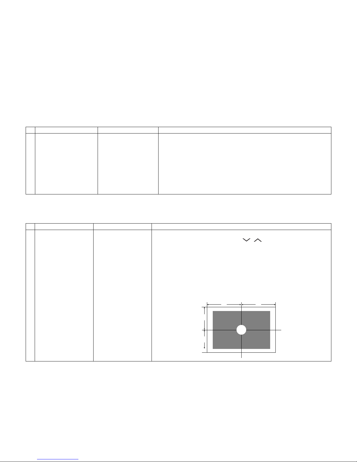
Adjustment item Adjustment conditions Adjustment procedure
1 Opposite bias adjustment
(LCD module adjustment
item)
Adjustment in the center
position of the panel
1) Enter the process mode using the process adjustment remote control.
2) Select [VCOM ADJ] using the Channel / keys on the remote control.
3) Press the Enter key to check that the pattern for adjustment is displayed.
4) Make adjustment so that the flicker located in the center of the screen is mini-
5) If the optimum condition is obtained in step 4, press the Enter key to turn off the
CAUTION: * Make adjustment with no ANT signal (since the brightness is changed
[Adjustment position]
mized using the Volume +/- keys on the remote control.
pattern.
by the active backlight).
5 – 10
Page 37
PRO-60/70X5FD
8.2. Image adjustment
8.2.1 Device check
Before adjustment, check that the adjustment jig and signal source are set for Sharp LCD US.
Signal generator level adjustment check (Adjust to the standard value level.)
• Composite signal: 0.714Vp-p ± 0.02Vp-p (Pedestal to white)
• 15K component signal: Y level: 0.714Vp-p± 0.02Vp-p (Pedestal to white)
PB/PR level: 0.7Vp-p ± 0.02Vp-p
• 33K component signal: Y level: 0.7Vp-p ± 0.02Vp-p (Pedestal to white)
PB/PR level: 0.7Vp-p ± 0.02Vp-p
• Analog RGB: RGB level: 0.7Vp-p ± 0.02Vp-p (Pedestal to white)
8.2.2 Process mode
Adjustment point Adjustment conditions Adjustment procedure
Process mode Enter the process adjustment mode using the process adjustment remote control.
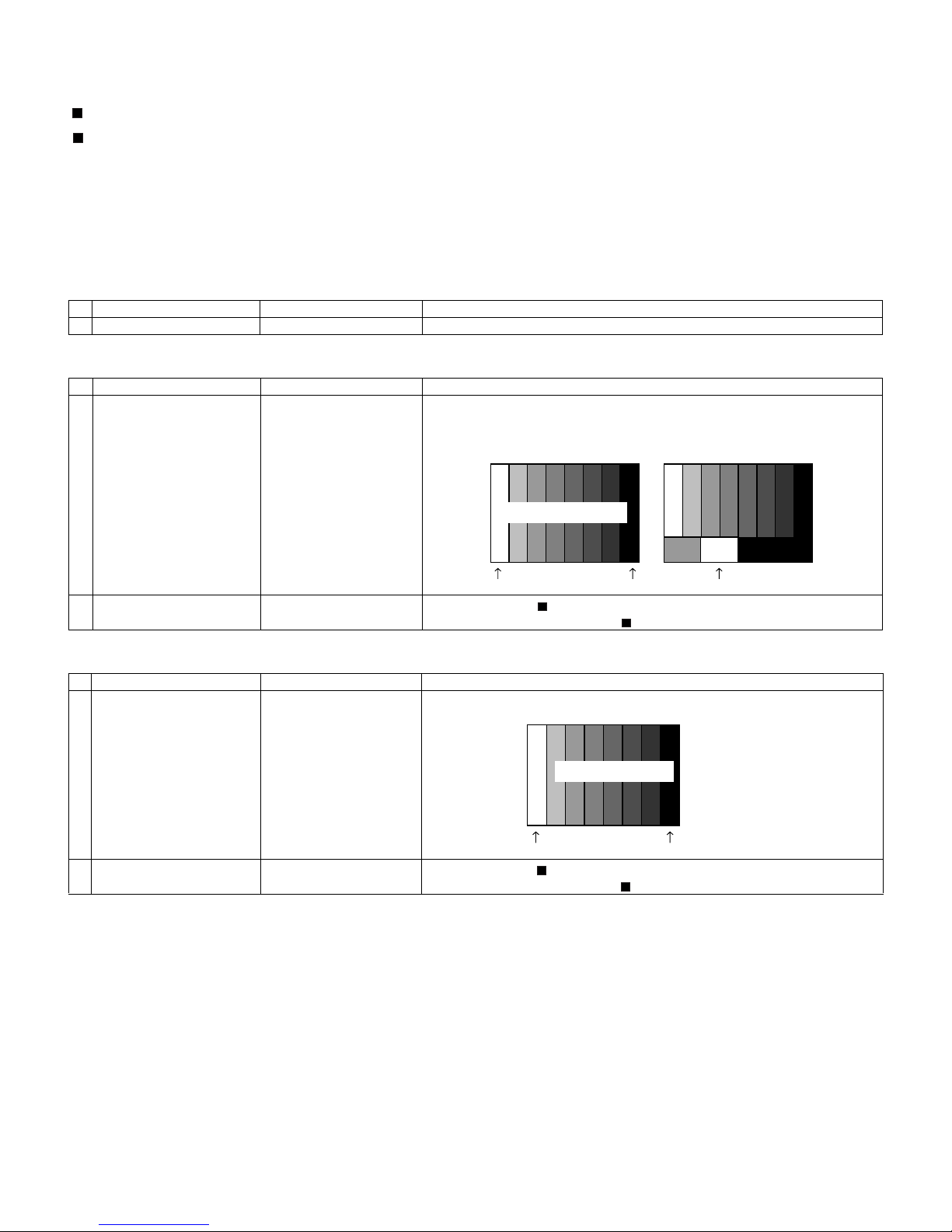
8.2.3 Composite N358 signal/tuner adjustment
Adjustment point Adjustment conditions Adjustment procedure
1 Setting N358 signal
US-10ch
• Send the N358 color bar (color saturation: 75%) signal to the composite input.
• Send the in-house signal (use US-10ch) to TUNER.
[Video input signal] [In-house US-10ch]
Color saturation: 75%
0% black
2 Automatic adjustment
execution
100% white 100% white
Point the cursor to [ N358 ALL ADJ(INPUT2)] and press the [Enter] key.
The adjustment is complete when [ N358 ALL ADJ(INPUT2) OK] is displayed.
8.2.4 Component 15K signal adjustment
Adjustment point Adjustment conditions Adjustment procedure
1 Setting 480i signal • Send the 100% color bar signal to the component input.
2 Automatic adjustment
execution
Color saturation: 100%
100% white 0% black
Point the cursor to [ COMP15K ADJ(INPUT1)] and press the [Enter] key.
The adjustment is complete when [ COMP15K ADJ(INPUT1) OK] is displayed.
480i
100% color bar
5 – 11
Page 38
PRO-60/70X5FD
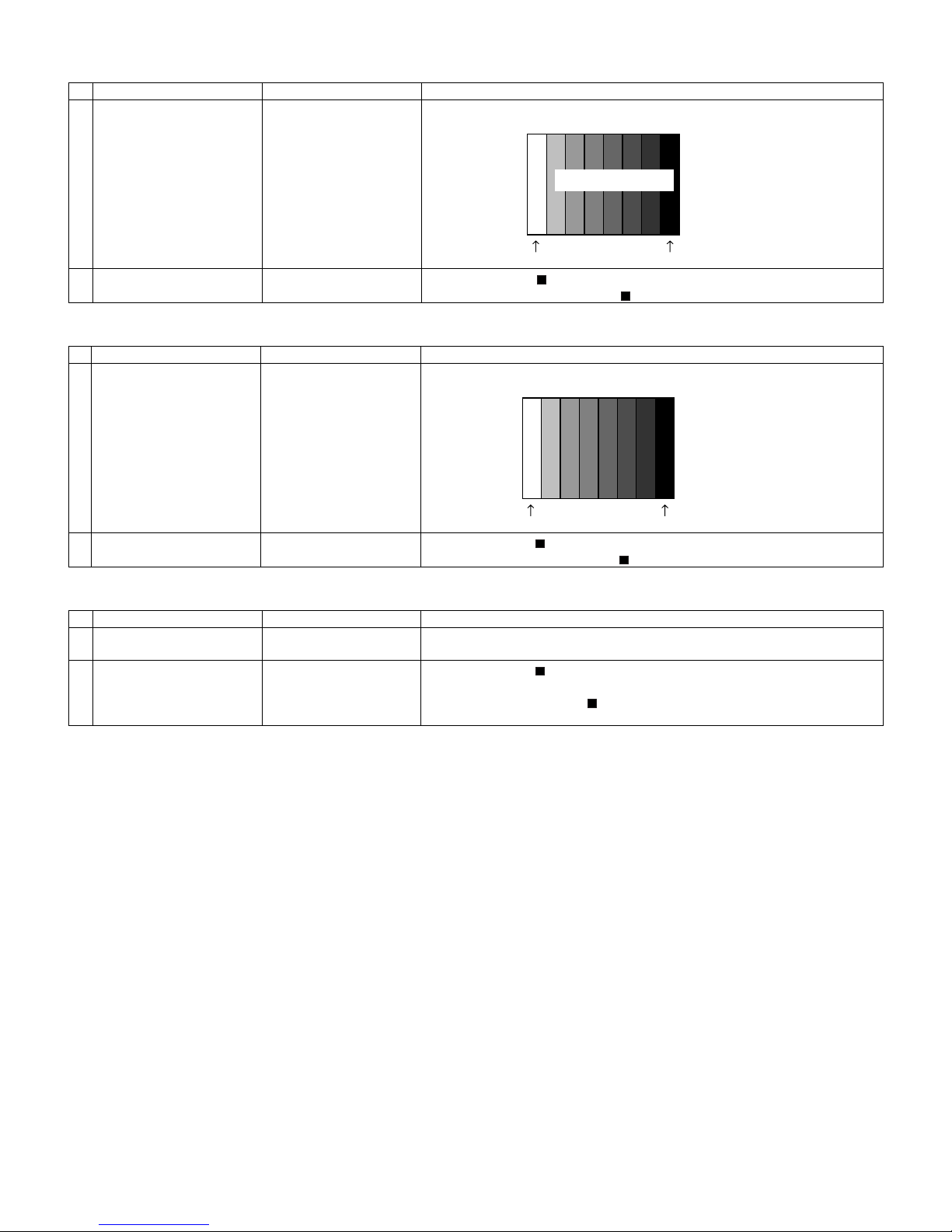
8.2.5 Component 33K signal adjustment
Adjustment point Adjustment conditions Adjustment procedure
1 Setting 1080i signal • Send the 100% color bar signal to the component input.
2 Automatic adjustment
execution
8.2.6 Analog RGB signal adjustment
Adjustment point Adjustment conditions Adjustment procedure
1 Setting Signal: XGA
(1024x768) 60Hz
SYNC: HV separate
2 Automatic adjustment
execution
8.2.7 Tuner/V-CHIP adjustment
Adjustment point Adjustment conditions Adjustment procedure
1 Setting NTSC RF signal
US-7(AIR)ch
2 Automatic adjustment
execution
Color saturation: 100%
100% white 0% black
Point the cursor to [ COMP33K ADJ(INPUT1)] and press the [Enter] key.
The adjustment is complete when [ COMP33K ADJ(INPUT1) OK] is displayed.
• Send the 100% color bar signal to the PC input.
100% white 0% black
Point the cursor to [ ANALOG RGB ADJ] and press the [Enter] key.
The adjustment is complete when [ ANALOG RGB ADJ OK] is displayed.
• Send the NTSC signal to the RF antenna input.
Point the cursor to [ VCHIP TEST(*07ch)] and press the [Enter] key.
(* Adjust the selected channel to the in-house signal.)
The adjustment is OK when [ VM-OK] is displayed in green.
(NG when VM-NG is displayed in red.)
1080i
100% color bar
XGA (1024x768)
100% color bar
5 – 12
Page 39
PRO-60/70X5FD
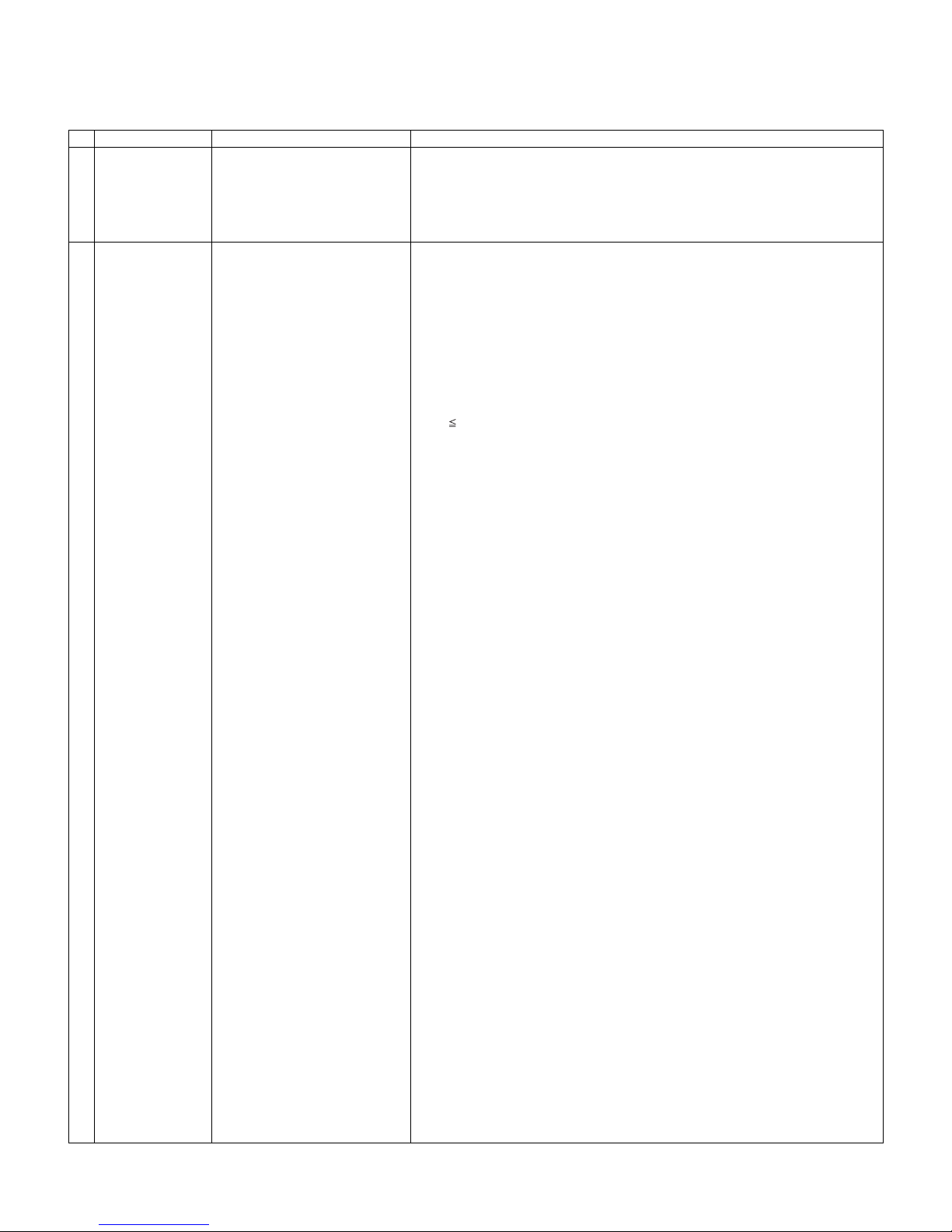
9. White balance adjustment
9.1. White balance adjustment (For details about the adjustment procedure, refer to “Kameyama Model Integrated Monitor
WB Adjustment Specification V1.92”.)
Adjustment point Adjustment conditions Adjustment procedure
1 Setting 1) Set the unit to the following conditions.
2 Automatic adjust-
ment execution
[Command]
Process mode
KRSW0001
KKT10037
Setting
KYOF0000
OSDS0001
SBSL0016
Multi-point adjustment mode
MSET0012
GC6P0011
White brightness measurement
GCP70255
Point 6
LEV60243
GCC6****
1G6G****
1G6B****
1G6R****
1G6Y****
MG6G****
MG6B****
MG6R****
MG6Y****
Point 5
LEV50229
GCC5****
1G5G****
1G5B****
1G5R****
1G5Y****
MG5G****
MG5B****
MG5R****
MG5Y****
Point 4
LEV40192
GCC4****
1G4G***
1G4B****
1G4R****
1G4Y****
MG4G****
MG4B****
MG4R****
MG4Y****
AV MODE: [DYNAMIC]
Backlight: +16
Active Backlight: OFF
Aging Time: Min. 60 minutes
2) Connect the unit with the white balance adjustment jig.
[Adjustment procedure]
1) Send the “adjustment process” code using the remote control.
2) Display white in GCP70255, and measure the brightness after a lapse of the wait
time of 100 ms; then send the decoupled value.
3) Set the point 6 to the specified gradation, and measure its brightness; then send
the decoupled value.
4) Specify the strongest color as the fixed color, and adjust the RGB by the 1G6*****
command so that it becomes the standard value through negative adjustment.
Then compare the R and G values; based on the result, calculate the Ye value in
the following conditions.
R > G: Ye = G x 1.05
R G: Ye = R x 1.05
* If the Ye value exceeds the initial value (input gradation x 4), it is rounded to
that value or less.
5) Set the adjustment value of the point 6 by MG6*****.
6) Set the point 5 to the specified gradation, and measure its brightness; then send
the decoupled value.
7) For the point 5, set the G correction value (916 x G value of point 6/972) (fractions rounded off) and the Ye correction value (916 x Ye value of point 6/972)
(fractions rounded off), and adjust the RB so that it becomes the standard value.
8) Set the point 4 to the specified gradation, and measure its brightness; then send
the decoupled value.
9) For the point 4, set the G correction value (768 x G value of point 6/972) (fractions rounded off) and the Ye correction value (768 x Ye value of point 6/972)
(fractions rounded off), and adjust the RB so that it becomes the standard value.
10)Set the point 3 to the specified gradation, and measure its brightness; then send
the decoupled value.
11)For the point 3, set the G correction value (600 x G value of point 6/972) (fractions rounded off) and the Ye correction value (600 x Ye value of point 6/972)
(fractions rounded off), and adjust the RB so that it becomes the standard value.
12)Set the point 2 to the specified gradation, and measure its brightness; then send
the decoupled value.
13)For the point 2, set the G correction value (432 x G value of point 6/972) (fractions rounded off) and the Ye correction value (432 x Ye value of point 6/972)
(fractions rounded off), and adjust the RB so that it becomes the standard value.
14)Set the point 1 to the specified gradation, and measure its brightness; then send
the decoupled value.
15)For the point 1, set the G correction value (192 x G value of point 6/972) (fractions rounded off) and the Ye correction value (192 x Ye value of point 6/972)
(fractions rounded off), and adjust the RB so that it becomes the standard value.
16)Write the adjustment value by the MSET0030 command.
17)Display black in GCP00000, and measure the brightness after a lapse of the wait
time of 100 ms; then send the centupled value.
18)Write the gamma adjustment value by GCST0001.
19)Write the WB adjustment value by MSET0030.
* RGB initial value of point 6: Set gradation 972
* RGB initial value of points 1 to 5: G correction value of each point
Point 3
LEV30150
GCC3****
1G3G****
1G3B***
1G3R****
5 – 13
Page 40
PRO-60/70X5FD
Adjustment point Adjustment conditions Adjustment procedure
1G3Y****
MG3G****
MG3B***
MG3R****
MG3Y****
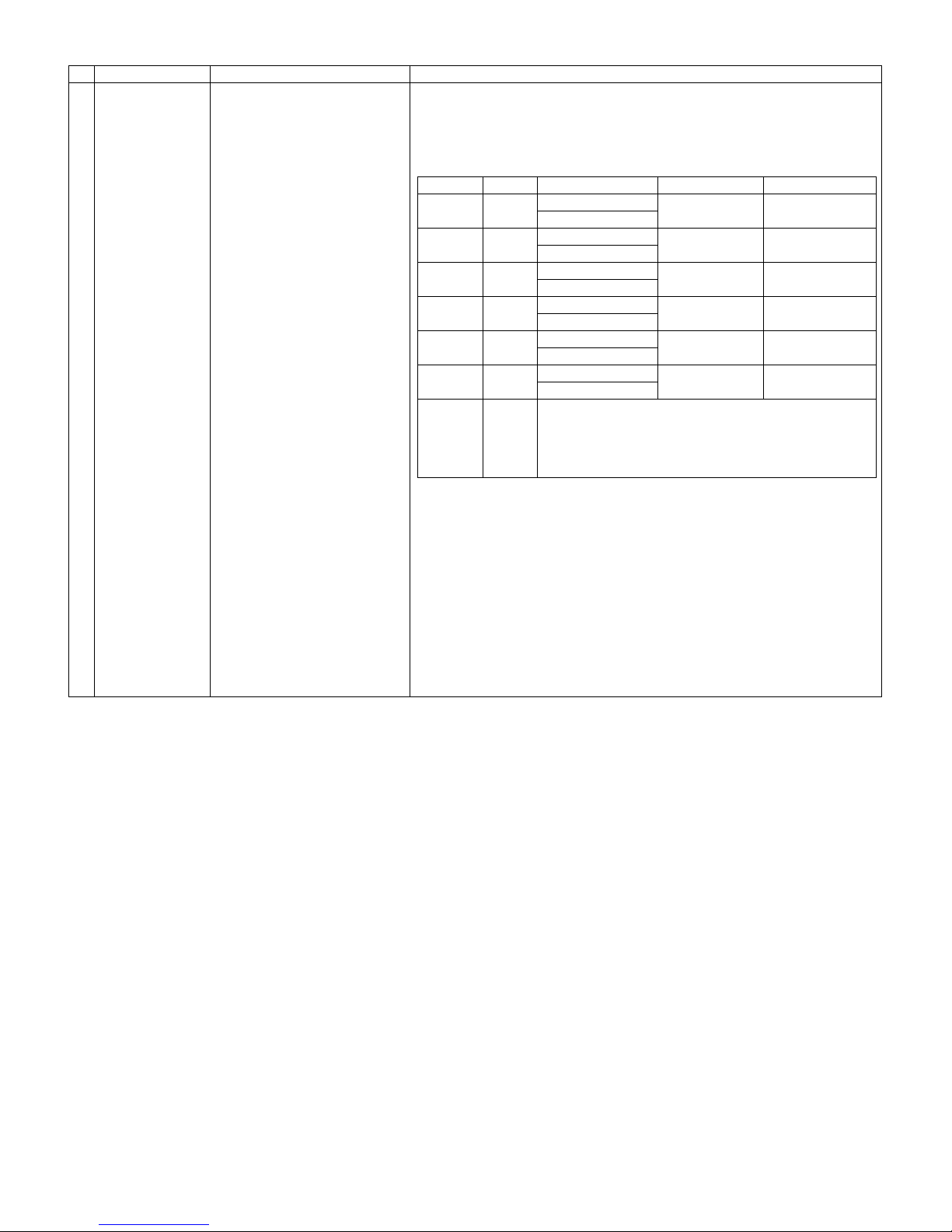
Point 2 Level Reference value Adjustment spec Inspection spec
LEV20108
GCC2**** y=0.3290
1G2G****
1G2B*** y=0.3290
1G2R****
1G2Y**** y=0.3290
MG2G****
MG2B*** y=0.3290
MG2R****
MG2Y**** y=0.3290
Point 1 y=0.3290
LEV10048
GCC1****
1G1G****
1G1B***
1G1R****
1G1Y****
MG1G****
MG1B***
MG1R****
MG1Y****
[Adjustment value]
* According to the “Standard settings” submitted by the Technical Department
[PRO-60X5FD] X5FD model teaching set
[Adjustment standard value]
Measuring instrument: [Minolta CA-210] Technical measuring instrument
Point 6 972
Point 5 916
Point 4 768
Point 3 600
Point 2 432
Point 1 192
Remarks Setting conditions for inspection
X=0.3127
X=0.3127
X=0.3127
X=0.3127
X=0.3127
X=0.3127
AV MODE: [DYNAMIC] (Reset)
Monochro: ON
Active Backlight: OFF
Aging Time: Min. 60 minutes
±0.0010 ±0.0020
±0.0010 ±0.0020
±0.0015 ±0.0030
±0.0020 ±0.0040
±0.0030 ±0.0060
±0.004 ±0.0080
Black brightness measurement
GCP00000
Gamma adjustment value storage
GCST0001
Writing
MSET0030
10. Key writing
10.1. MAC key writing (MAIN PWB: QPWBXF733WJN2)
1. Write the MAC key data on IC8455 mounted on the main PWB.
2. Carry out thorough data management to avoid redundant writing of data.
If the IC where data is written is damaged, replace the PWB since only the IC cannot be changed.
10.2. NETFLIX/WMDRM key writing (MAIN PWB: QPWBXF733WJN2)
1. Write the NETFLIX/WMDRM key data on IC8401 mounted on the main PWB.
2. Carry out thorough data management to avoid redundant writing of data.
If the IC where data is written is damaged, replace the PWB since only the IC cannot be changed.
10.3. Wide Vine key writing (MAIN PWB: QPWBXF733WJN2)
1. Write the wide vine key data on IC8401 mounted on the main PWB.
2. Carry out thorough data management to avoid redundant writing of data.
If the IC where data is written is damaged, replace the PWB since only the IC cannot be changed.
NOTE: For EDID of the analog RGB (DSUB 15pin), write the data on the process menu just like HDMI.
5 – 14
Page 41
PRO-60/70X5FD
11. Factory setting
After completing the factory setting, pull out the AC cord to complete the setting.
CAUTION: Do not turn on the power after completing the factory setting. If the power is turned on, configure the factory setting again.
Adjustment point Adjustment conditions Adjustment procedure
1 Factory setting Complete the setting by
pulling out the AC cord.
12. Software version
1. Main microcomputer
BSMK_X5FD_xxx.USB
BSMK_X5FD_xxx.DAT
BSMK_X5FD_xxxxxxx.PCC
2. Monitor microcomputer
BMELMxxx.SMB
• Point the cursor to [INDUSTRY INIT (+Cause)], set to “ON” using [+]/[-] of the [VOL]
key, and press the [ENT] key.
The version confirmation screen appears on the green screen. It is completed when
[SUCCESS] is displayed at the top.
(If error occurs, [ERROR] is displayed on the red screen.)
• Turn off the AC power.
The following items are initialized when configuring the factory setting.
1) User set value
2) Channel data (broadcasting frequency, etc.)
3) Password setting value
4) Operating time
5) Standby Cause
6) Auto installation flag
7) V-CHIP block setting value
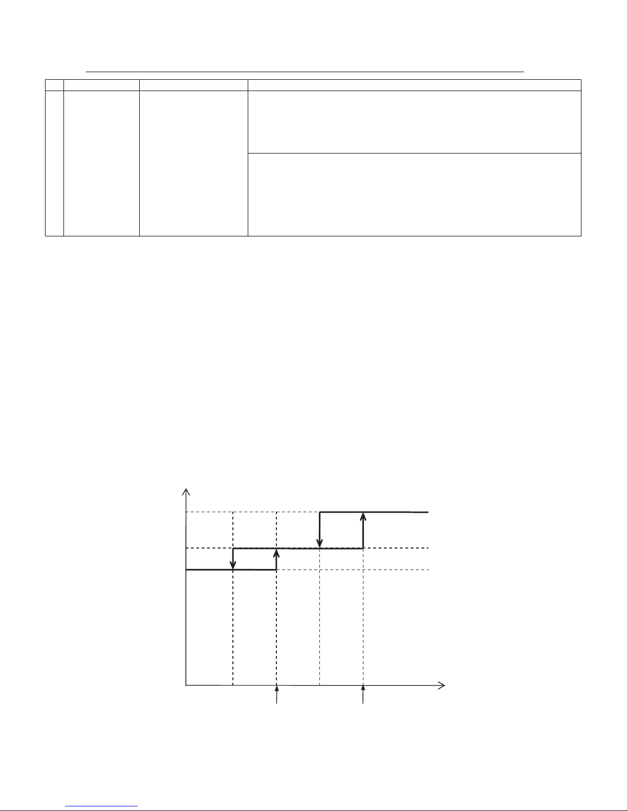
13. An anti-crosstalk measure at the time of the low temperature
• It is a function to control a picture gain depending on the value of the thermistor on the board to reduce crosstalk at the time of the low temperature.
• The value of the thermistor is confirmed in “TEMPERATURE” of 1/29 pages menus in a process.
• When change the parameter of this function, turn on “CROSSTALK ADJ MODE” of 25/29 pages menus in a process.
• The other parameters of 25/29 pages menus support the following graph in a process.
• For a function to control a picture gain, a screen darkens depending on setting.
• Because the most suitable value is set by default, please do not usually change it.
Picture gain
CROSSTALK GAIN1
CROSSTALK GAIN2
CROSSTALK GAIN3
CROSSTALK TH4
CROSSTALK TH2
CROSSTALK TH3
5 – 15
Panel surface temperature
CROSSTALK TH1
(A thermistor value)
Page 42
PRO-60/70X5FD
[2] PUBLIC MODE SETTING PROCEDURE
1. How to start Public Mode
• There are the following two ways to get the public mode setup screen displayed.
In the adjustment process mode, turn on “PUBLIC MODE”. Also press the “CH ( )” and “VOL (+)” keys on the set at once and turn on the
power.
1) Press the “INPUT” and “VOL (+)” keys on the set at once and turn on the power.
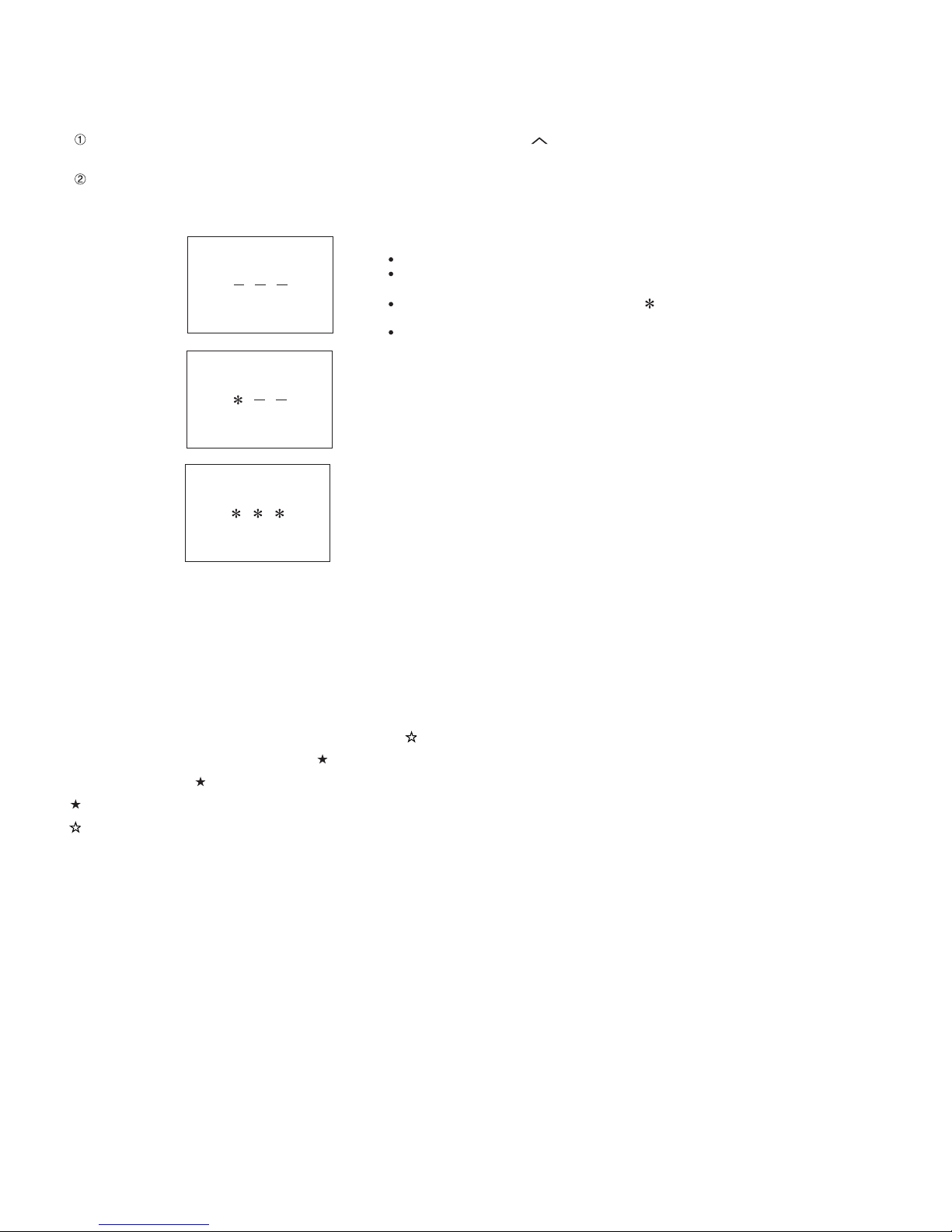
2) Get the password input screen displayed.
Procedure
˴The input starts with the leftmost digit.
˴Use the numeric keys [1] thru [9] and [0] keys on the remote controller.
˴The other keys are not acceptable.
˴With a numeric-key input, "_" will change to "˴".
˴The input position will move one digit to the right.
˴With all the 3 digits entered, the password will be verified.
3) The 3-digit password is now verified.
The password [0] [2] [7] provides for the public mode screen. (This screen comes on with whatever adjustment process settings.)
With any other passwords, the screen changes to the normal mode.
2. How to exit Public Mode
There are the following ways to quit the public mode setup screen.
• Turn off “PUBLIC MODE” in the adjustment process mode. ( ) ← This way alone is not for quitting the setup screen, but for quitting the mode itself.
• Turn off the power with the “POWER” key. ( )
• Select “EXECUTE”. ( )
... “PUBLIC MODE” stays on in the adjustment process mode.
... The settings will be back to the factory ones.
3. Public Mode Setting Values
• With the factory settings made, the public mode settings get initialized. (The adjustment process remains intact.)
5 – 16
Page 43
PRO-60/70X5FD
4. Public Mode Menu
The guidance is not displayed on screen.
Setup procedure
• To move the cursor up and down, use the “cursor UP/DOWN” key (remote controller) and “CH ( )/( )” key (remote controller and set).
• To change the settings, use the “cursor RIGHT/LEFT” key (remote controller) and “VOL (+)/(–)” key (remote controller and set).
• To save new settings, keep the cursor at “EXECUTE” and use “ENTER” key (remote controller and set).
PUBLIC MODE
POWER ON FIXED [VARIABLE ]
MAXIMUM VOLUME [ 60 ]
VOLUME FIXED [VARIABLE ]
VOLUME FIXED LEVEL [ 20 ]
RC BUTTON [RESPOND ]
PANEL BUTTON [RESPOND ]
MENU BUTTON [RESPOND ]
AV POSITION FIXED [VARIABLE ]
ON SCREEN DISPLAY [YES ]
INPUT MODE START [NORMAL ]
INPUT MODE FIXED [VARIABLE ]
LOUD SPEAKER [ON ]
RC_PATH_THROUGH [OFF ]
232C POWON [DISABLE ]
PUBLIC MODE [OFF ]
RESET
EXECUTE
COPY MODE
5 – 17
Page 44
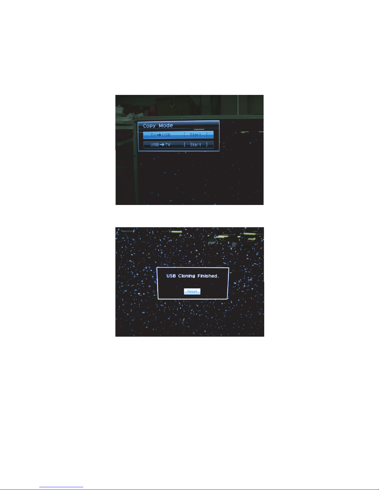
PRO-60/70X5FD
[How to use USB clone]
This is the function that copying the one TV's user setting to other TVs or copying previous user setting to itself.(Only same series.)
1. Insert the USB memory to TV.
2. Insert AC code of TV with pushing the “INPUT” and “Vol+” keys which are on the tact key.
3. Enter the passward by using R/C. The passward is “027”.
4. Select “COPY MODE”.
5. The follow guide is displayed. Then select the “TV→USB [Start]”.
6. Follow guide is displayed when it is finished , then select "Reset" . TV will restart.
7. Insert the USB which has the data from TV to another TV or itself.
8. Insert AC code of the TV with pushing the "INPUT" and "Vol+" keys which are on the tact key.
9. Select “COPY MODE”.
5 – 18
Page 45
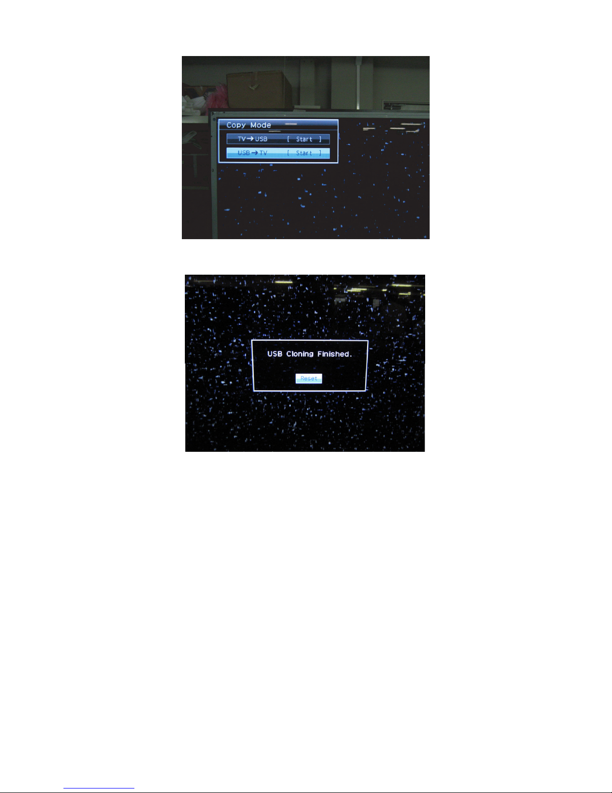
10.The following guide is dispalyed.Then select the “USB→TV [Start]”.
11.Follow guide is displayed when it is finished , then select "Reset" . TV will restart.
PRO-60/70X5FD
12.Comfirm the user setting is copied.
5 – 19
Page 46
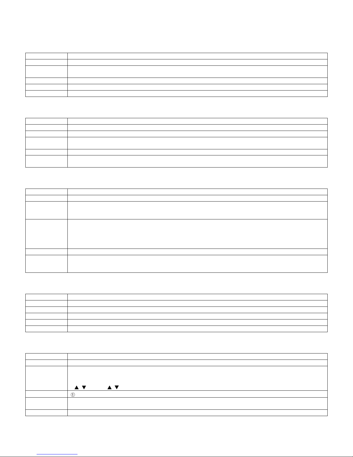
PRO-60/70X5FD
5. On Setting Items
* “EZ-SETUP” discussed below indicates “EZ-SETUP after the first power-on”.
1) POWER ON FIXED
Selection Selection between “Variable” and “Fixed” (loop provided)
Default – (Variable)
Explanation In “Fixed” setting, the power-off by the power key of the unit is invalidated and the image is kept being received. The power can
Limit in Setting Refer to the “Power-On Fixed” sheet.
Exception None
Remarks • In “Variable” setting, the power operation is in wait for 1 sec. and then turned off when the main power switch is off.
2) MAXIMUM VOLUME
Selection Adjustment from 0 to 60 (no loop)
Default 60
Explanation Sound volume can not be adjusted higher than the preset value.
Limit in Setting • When the sound volume is set lower than 59, only figures are displayed and the sound volume bar is not displayed.
Exception
Remarks • When the sound volume is set higher than the MAX setting by the adjusting process, the sound volume control operation is
3) VOLUME FIXED
Selection Selection between “Variable”, “Fixed”, “ACON (AC CTRL)” and “AC/RCON (AC/RC CTRL)” (loop provided)
Default Variable
Explanation • FIXED: Fixed at the level adjusted for a fixed volume.
Limit in Setting • The sound volume for the ON-timer (Wake up timer) is fixed also without display of menu. Besides, the setting is made
Exception • In the item “VOLUME” of adjustment process, the sound volume can be set freely irrespective of this setting.
Remarks • As for sound volume fixing and sound volume MAX level, the sound volume fixing has priority.
4) VOLUME FIXED LEVEL
Selection Adjustment from 1 to 60 (no loop)
Default 20
Explanation The sound volume to be fixed by “Volume fixed” is determined.
Limit in Setting None
Exception None
Remarks Setting is valid only when “Volume fixed” is selected for “fixed”.
be turned off by stopping the power supply from AC.
• The maximum sound volume for ON-timer (Wake up timer) is limited also to the preset value.
prohibited for turn-up and the sound volume should be turned down to MAX in this state.
• AC CTRL: Start-up at the level specified for a fixed volume at ACON.
• AC/RC CTRL: Start-up at the level specified for a fixed volume at start.
impossible. (Basically, the menu is not displayed.)
• The following keys become invalid:
• Sound volume Up/Down (VOL +/–) [for both remote control and the unit]
• Mute (MUTE)
• Once the sound volume has been changed by adjustment process, it should be set back to the sound volume preset by
sound volume fixing level when the adjustment process ends.
5) RC BUTTON
Selection Selection between “Respond”, “No Respond” and “Limited” (loop provided)
Default Respond
Explanation Making the remote controller settings.
Limit in Setting
Exception • Adjustment process, inspection process and hotel only keys are valid irrespective of setting.
Remarks
• At the “No Respond” setting, the remote controller keys are disabled. Its power key (reception/standby key) is disabled too.
• At the “Limited” setting, some channel-related keys alone are operative. All the other remote controller keys (power, volume
/ , channel / , light control (brightness sensor), broadcast select) are inoperative.
In “No respond” setting, all the keys (including the power key) are not accepted.
• All the keys can be used in adjustment process, inspection mode and hotel menu irrespective of setting.
5 – 20
Page 47
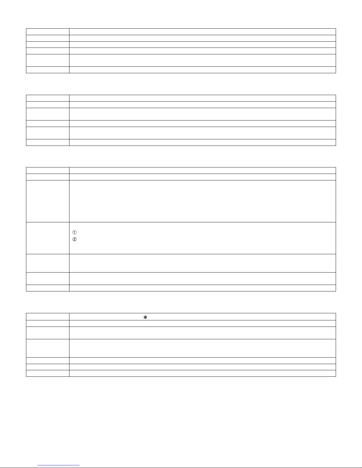
PRO-60/70X5FD
6) PANEL BUTTON
Selection Selection between “Respond” and “No respond” (loop provided)
Default Respond
Explanation All the operations by keys (except the power key) of the unit can be invalidated.
Limit in Setting
Exception • Adjustment process, inspection mode and hotel menu mode can be started irrespective of setting.
Remarks
7) MENU BUTTON
Selection Selection between “Respond” and “No respond” (loop provided)
Default Respond
Explanation In “No respond” setting, the menu operation by the menu key of the remote control and the menu key of the unit are invali-
Limit in Setting
Exception • Adjustment process, inspection mode and hotel menu mode can be started irrespective of setting.
Remarks
8) ON SCREEN DISPLAY
Selection Selection between “Yes”, “No” (loop provided)
Default Yes
Explanation • At the “No” setting, the following items are not displayed on screen: register, setting, adjustment menu, channel call and
Limit in Setting • Keys falling under any of the following items become invalid.
Others • Simple input switching is generated. Those which are restored soon after leaving as they are and may be requested for
Exception • Such a caution which is displayed independently is displayed as it is.
Remarks • When CC has already been ON, CLOSED CAPTION is displayed.
9) INPUT MODE START
Selection
Default Normal
Explanation In power-ON, the input source to be started or channel can be set.
About options • All the input sources in the model are made selectable.
Limit in Setting • The display of channel setting menu and the channel setting operation are prohibited.
Exception
Remarks • In setting at “Normal”, the setting of “Input mode fixed” is changed to “Variable” and selection should be prohibited.
• All the keys can be used in adjustment process, inspection mode and hotel menu irrespective of setting.
dated.
• All the keys can be used in adjustment process, inspection mode and hotel menu irrespective of setting.
volume bar.
On the wide-screen models, an input selection is immediately made because the menu is not displayed.
• At the “Limited” setting, some items cannot be displayed on screen.
On the Japan-destined models, the channel call “Message” alone cannot be displayed. (This is because the channel call
message may be confused with a message being sent from the hotel.)
On the North America-destined models, the OSD works the same as at the “No” setting.
Appearance of screen changes and the sound changes.
Personal functions which are hard to restore.
Screen display, menu, OFF-timer, ON-timer, AV MODE, screen size switching, clock setting, treble emphasis, AUDIO ONLY,
sound changeover, LANGUAGE, CLOSED CAPTION
change by customer are not prohibited.
Brightness sensor (BACKLIGHT) and PIC. FLIP
Non-responding signal caution
Selection between “Normal”, “Air ( )”, “INPUT 1/2/3”, “PC”, “HDMI 1/2/3/4/5”, “DVI” (loop provided)
(In standard mode, the operation follows the last memory.)
• In TV mode, the channel to be set follows the last memory and the content of the last memory is included in the notation by
options. Ex.) Air (2), Cable (98.1) etc.
5 – 21
Page 48
PRO-60/70X5FD
10)INPUT MODE FIXED
Selection Selection between “Variable”, “Fixed”, “ACON (AC CTRL)” and “AC/RCON (AC/RC CTRL)” (loop provided)
Default – (Variable)
Explanation • At the “Fixed” setting, the TV set gets started with the settings of “Input mode start”, and then any other channels and inputs
Limit in Setting • With the execution of hotel mode, the input source is forced to change to that set by “Input mode start” and the channel
Exception None
Remarks • In the following case, setting is cancelled and mode is changed to “Variable”.
11)RC_PATH_THROUGH
Selection Selection between “OFF”, “ON: TV RCE” and “ON: TV RCD” (loop provided)
Default OFF
Explanation Function to feed the remote controller-received signal to Pin 9 (open) on the RS232C.
Limit in Setting None
Exception None
Remarks None
12)AV POSITION FIXED
Selection Selection between “Variable” and “Fixed” (loop provided)
Default Variable
Explanation In case of “Fixed” setting,
Limit in Setting None
Exception None
Remarks • When receiving with AV Position key, OPC, Dolby key and other direct audio select keys, the current display stays on and no
are not accepted.
• At the “ACON (AC CTRL)” setting, the TV set gets started with the settings of “Input mode start” under AC control.
• At the “AC/RCON (AC/RC CTRL)” setting, the TV set gets started with the settings of “Input mode start” under either control.
switching and input switching are prohibited thereafter.
• ON-timer's (Wake-up timer) channel items are not displayed or the operation is prohibited. (Basically, they are not displayed.)
• The following keys are invalidated.
CH / , direct tuning button, FLASHBACK, input
However, the keys (input switching and CH / keys) of the unit for menu operation remain valid.
When the setting of “Input mode start” is set to “Normal”.
– Menu “Picture” and “Audio” setting can't be changed like “Dynamic (Fixed)”.
– When “AV Mode” key is pressed, TV just displays current AV Mode (cannot be changed.).
setting can be changed.
• Even by initializing personal information, the hotel-mode settings are kept intact. In this way, the AV positions, video and
audio adjustment settings are not initialized.
13)LOUD SPEAKER (ON/OFF)
Selection Selection between “ON” and “OFF” (loop provided)
Default ON
Explanation If “OFF” is selected, TV stops Speaker output even without Headphone connected.
Limit in Setting None
Exception None
Remarks • Press the volume UP/DOWN key, and the mute icon appears for 4 seconds.
14)232C POWON
Selection Selection between “Disable” and “Enable” (loop provided)
Default Disable
Explanation In the standby mode, the power-on by the 232C command is enabled or disabled.
Limit in Setting None
Exception None
Remarks None
• The mute key and audio-related keys are displayed with caution.
• Usually, the headphones and monitor audio outputs can be adjustable.
5 – 22
Page 49
15)PUBLIC MODE (ON/OFF)
Selection Selection between “ON” and “OFF” (loop provided)
Default OFF
Explanation In case of “ON”, public mode settings are effected.
Limit in Setting None
Exception None
Remarks The public-mode settings are operable only when this item is set at ON.
PRO-60/70X5FD
5 – 23
Page 50
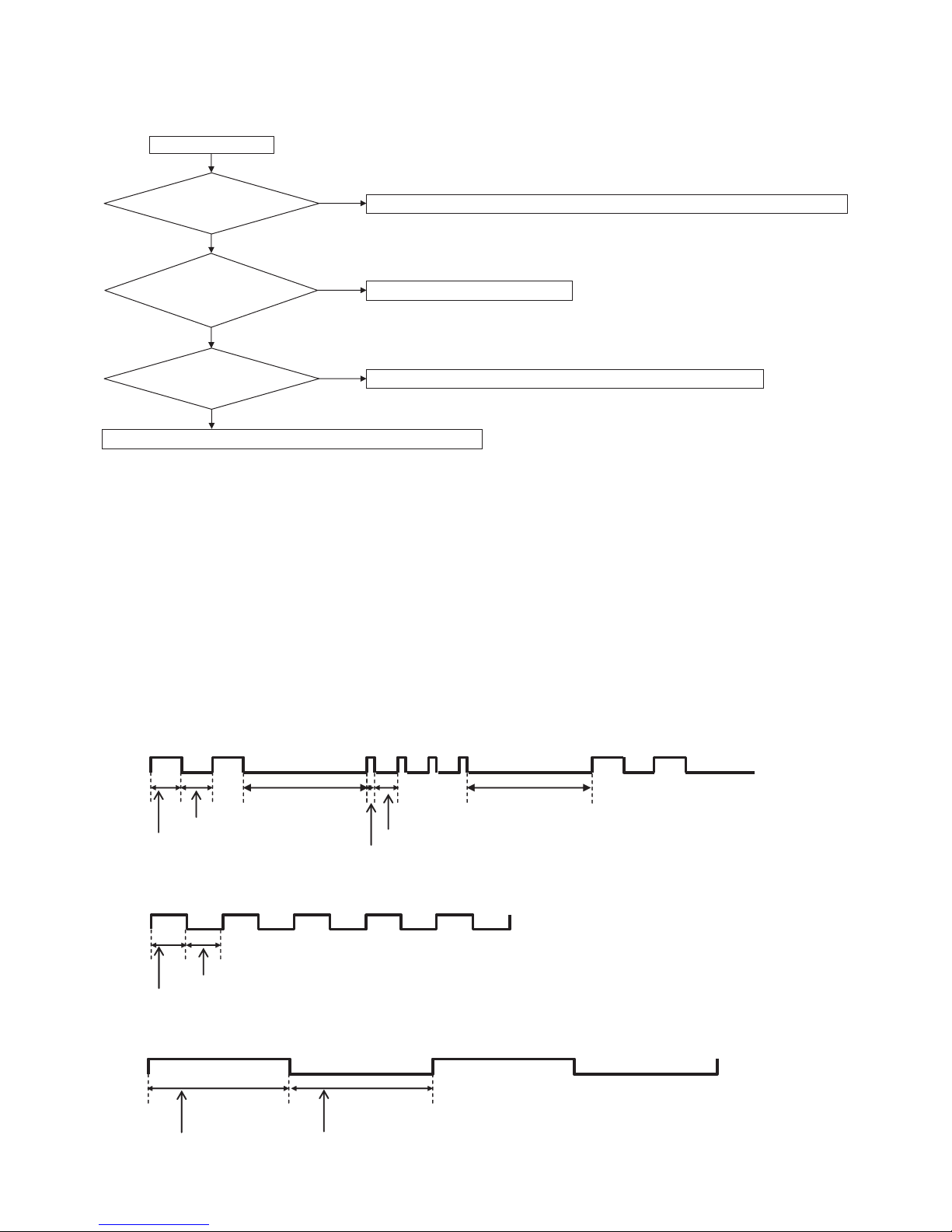
PRO-60/70X5FD
PRO60X5FD
CHAPTER 6. TROUBLESHOOTING TABLE
Service Manual
[1] Failure diagnosis by LED in front of cabinet
START
Is the Center Icon flashing?
No
Is the Center Icon lighting
When AC plug on?
Yes
Is the Backlight lighting?
Yes
Check "Picture does not display.".
Yes
No
No
Check "[2] LED flashing specification at the time of an error (Center icon LED used)".
Check Power-Unit and AC-cable.
Check "LED Backlight does not turn on.".
[2] LED flashing specification at the time of an error (Power LED used)
1. Display method
• Refer to Tables 1 and 2.
• Since only one power LED is used, slow flashing and fast flashing are combined.
• The Start from the detail display. (No outline display)
• After recovering from an error, if the same error cannot be generated again, refer to MONITOR ERR CAUSE on the process screen.
• During version upgrade or when completing it, the flashing cycle changes.
2. LED flashing method
Error flashing
<Detail display example>
Power LED
400ms
400ms
• Flashing during Verup
Power LED
500ms
500ms
• Flashing when completing Verup
Power LED
1600ms
1600ms
300ms
100ms
2000ms
2000ms
6 – 1
Page 51
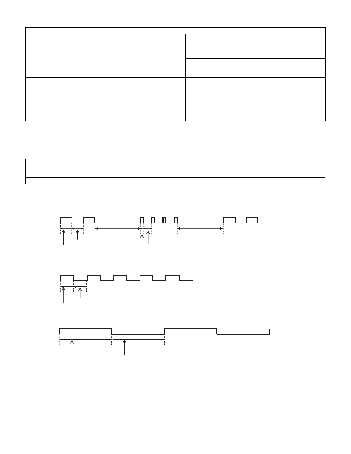
Table 1. Concrete flashing pattern (Error standby)
PRO-60/70X5FD
Item
Inverter/Lamp system
failure
Power PWB failure
(Power failure, etc.)
Main PWB failure
(Communication failure, etc.)
Others Flashes 4 times None Flashes 4 times Flashes once Temperature error
*2: They depend on the system. Power supply error is defined from product to product.
*3: For details, refer to ERROR STANDBY CAUSE on the adjustment process screen.
Table 2. Concrete flashing pattern (Verup, etc.)
Item Display Note
Ver UP executing Flashes continuously (1 sec cycle) The flash only when rewriting the sub microcomputer.
Ver UP succeeded Flashes continuously (4 sec cycle) The flash only when rewriting the sub microcomputer.
ROM data failure Flashes continuously (400 msec cycle, On period: 100 msec) Start-up after failing version upgrade (*4)
*4: If the boot section is abnormal, there is no flashing (flashing impossible).
Flashes once None Flashes once Flashes once Lamp error
Flashes twice None Flashes twice Flashes once Power supply error 1 (*2) AC_DET error
Flashes 3 times None Flashes 3 times Flashes once Initial communication error
Outline display Detail display
Slow flashing Fast flashing Slow flashing Fast flashing
Flashes twice Power supply error 2 (*2) UR+13V error
Flashes 3 times Power supply error 3 (*2) D3.3V error
Flashes 5 times Panel power supply error
Flashes twice Start-up confirmation communication error
Flashes 3 times Regular communication error
Flashes 5 times Other communication error
Flashes twice Sync error
Flashes 3 times Notification from the main microcomputer (*3)
Cause
3. New method
PowerLED
400ms
400ms
• Flashing during Verup
Power LED
500ms
500ms
• Flashing when completing Verup
Power LED
2000ms
1600ms
2000ms
1600ms
300ms
100ms
6 – 2
Page 52
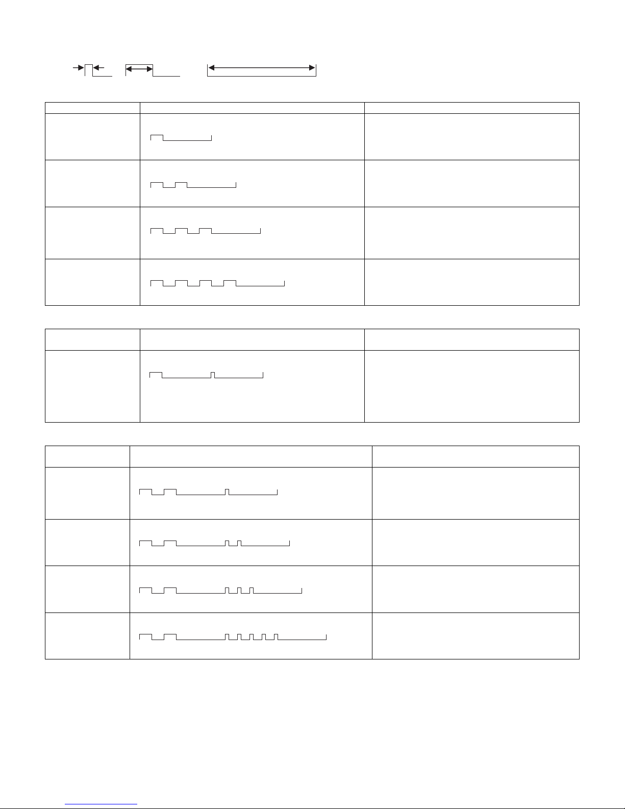
PRO-60/70X5FD
LED flashing timing chart at the time of an error
100ms 400ms 1.6sec
1) Slow flashing Note
Error type Power LED operation Pins are monitor microcomputer pins.
Inverter/Lamp failure
Flashes slowly once
Power failure
Flashes slowly twice
Main CPU to main CPU
communication failure
Flashes slowly 3 times
Others
Flashes slowly 4 times
2) Inverter/Lamp failure details (Flashes slowly once and flashes fast) Note
Error type Power LED operation
Lamp failure
Flashes fast once
3) Power failure details (Flashes slowly twice and flashes fast) Note
Error type Power LED operation
PS_ON
AC_DET failure
Flashes fast once
SM_POW
Main 13V failure
Flashes fast twice
D_POW
Digital 3.3V error
Flashes fast 3 times
PANEL_POW
Panel 12V failure
Flashes fast 5 times
H: On
L: Off
H: On
L: Off
H: On
L: Off
H: On
L: Off
H: On
L: Off
H: On
L: Off
H: On
L: Off
H: On
L: Off
H: On
L: Off
Refer to “Inverter/Lamp failure details”.
Flashes slowly and fast by pressing the [MENU] key on
the remote control (refer to 2 below).
Refer to “Power failure details”.
Flashes slowly and fast by pressing the [MENU] key on
the remote control (refer to 3 below).
Refer to “Communication failure details”.
Flashes slowly and fast by pressing the [MENU] key on
the remote control (refer to 4 below).
Communication line failure or main CPU communication
failure. → Check debug statements for the main CPU.
Refer to “Other failure details”.
Flashes slowly and fast by pressing the [MENU] key on
the remote control (refer to 5 below).
Pins are monitor microcomputer pins unless otherwise specified.
ERR_PNL: Hi failure. Confirmed after 8 consecutive
detections at 64 msec intervals (detected only when the
backlight is on).
Note that after five detection counts, the lamp cannot be
activated except in the monitor process.
Accumulated counts are cleared to 0 by the setting in the
process A.
Pins are monitor microcomputer pins unless otherwise specified.
AC_DET failure (L).
If error is detected during start-up or operation, the
power is turned on again by interrupt (instantaneous
blackout processing).
DET_13V failure (L). Main 13V is not applied.
If error is detected during operation, error standby is
activated by polling.
DET_D3V3 failure (L). Digital 3.3V is not applied.
If error is detected during operation, error standby is
activated by polling.
DET_PNL12V failure (L). Panel power is not applied.
If error is detected during operation, error standby is
activated by polling.
6 – 3
Page 53
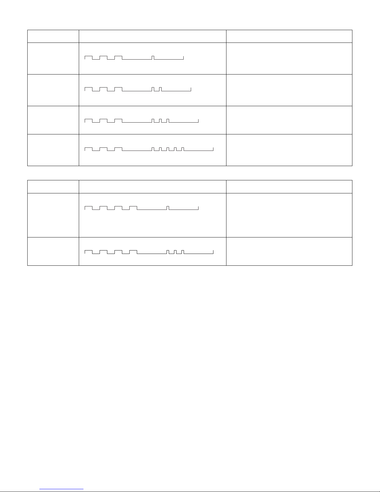
4) Communication failure details (Flashes slowly 3 times and flashes fast) Note
Error type Power LED operation
Initial communication reception failure
Flashes fast once
Start-up confirmation reception failure
Flashes fast twice
Regular communication failure
Flashes fast 3 times
Other communication failure
Flashes fast 5 times
5) Other failure details (Flashes slowly 4 times and flashes fast) Note
Error type Power LED operation
Monitor temperature
failure
Flashes fast once
Main failure
Flashes fast 3 times
H: On
L: Off
H: On
L: Off
H: On
L: Off
H: On
L: Off
H: On
L: Off
H: On
L: Off
Basically, debug print logs are analyzed or communication logs are analyzed by a bus monitor.
Initial communication from the main CPU is not
received. (Request for the monitor model No. is not
received.)
→ Communication line failure or main CPU start-up failure
Start-up reason confirmation from the main CPU cannot
be received. (Start-up communication until start-up reason notification command is not received.)
→ Main CPU start-up failure or monitor microcomputer
reception failure
Regular communication that is performed at 1 second
intervals in the normal operation is interrupted.
→ Main CPU operation failure or monitor microcomputer reception failure
When a request (PM_REQ=H) is sent from the main
microcomputer, the request command is not output
from the main CPU, etc.
→ Main CPU operation failure or monitor microcomputer reception failure
Pins are monitor microcomputer pins unless otherwise specified.
If the panel temperature is 60°C or more for 15 seconds
or more in a row, CAUTION appears on the OSD
(flashes in red in the lower right screen).
If the panel temperature is 60°C or more for 25 seconds
or more in a row, error standby is activated.
(MONITOR MAX TEMP on page 23 of the process A:
Change of temperature failure AD value): Thermistor
Main microcomputer detection error (CPU temperature
error, etc.)
The details are displayed on page 1 of the process A of
the main microcomputer.
PRO-60/70X5FD
6 – 4
Page 54
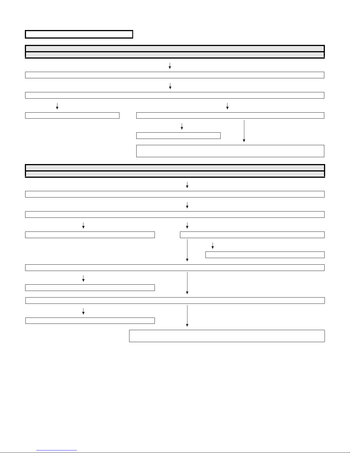
PRO-60/70X5FD
[3] TROUBLESHOOTING TABLE
• LED Backlight does not turn on.
If it is not an error of power supply/LED driver,
It is start-up in the lamp error disregard mode.
Do you start?
YES
When main unit is replaced, does it start normally?
YES NO
Replace main unit. en LCD control unit is replaced, does it start normally?
YES
Replace LCD control unit.
When the parts in the panel can be replaced. →Replace all LED-bars in the panel module.
When the parts in the panel cannot be replaced. →Replace panel module.
If it is not an error of power supply/LED driver,
It is start-up in the lamp error disregard mode.
NO
Do you start?
NO
When power supply unit is replaced, does it start normally?
YES NO
Replace power supply unit. When LED driver unit is replaced, does it start normally?
YES
Replace LED driver unit.
NO
When main unit is replaced, does it start normally?
YES
Replace main unit.
NO
When LCD control unit is replaced, does it start normally?
YES
Replace LCD control unit.
NO
When the parts in the panel can be replaced. →Replace all LED-bars in the panel module.
When the parts in the panel cannot be replaced. →Replace panel module.
6 – 5
Page 55
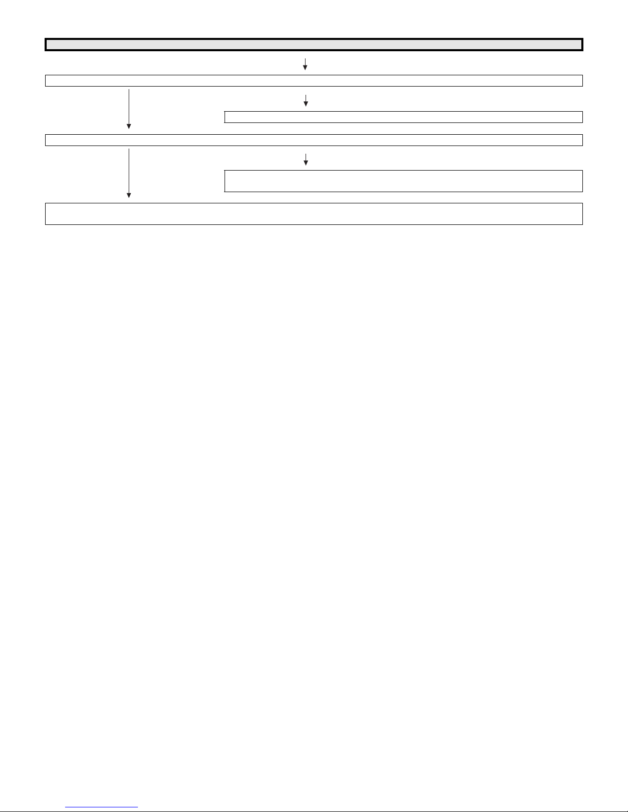
Trouble Shooting Panel Module
When C-S FPC (4pieces) is replaced, does screen display normally?
Replace C-S FPC (4pieces).
NO
When C-PWB is replaced, does screen display normally?
Replace C-PWB.
(Adjust “VCOM ADJ” after replace C-PWB)
NO
Replace Panel HIRAKI.
(Adjust “VCOM ADJ” after replace Panel HIRAKI)
PRO-60/70X5FD
YES
YES
6 – 6
Page 56
PRO-60/70X5FD
• Picture does not display.
No video (1)
COMPOSITE: No external input video [INPUT-7] COMPOSITE: No external input video [INPUT-8]
Is INPUT-7 selected on the input select menu screen? Is INPUT-8 selected on the input select menu screen?
NO
Select INPUT-7 on the input select menu
screen for the right input signal.
YES
Is there the COMPOSITE signal input at pin (AJ23) of
IC3303 (CPU)?
NO
Check the line between pin (10) of J510
and pin (AJ23) of IC3303.
YES
Are the LVDS signal input to the pin of P2601?
LVDS0_FPGA_D0P/N (39/40pin), LVDS0_FPGA_D1P/N (37/38pin),
LVDS0_FPGA_D2P/N (35/36pin), LVDS0_FPGA_D3P/N (30/31pin),
LVDS0_FPGA_D4P/N (28/29pin), LVDS0_FPGA_CLKP/N_74MHz (32/33pin),
LVDS1_FPGA_D0P/N (25/26pin), LVDS1_FPGA_D1P/N (23/24pin),
LVDS1_FPGA_D2P/N (21/22pin), LVDS1_FPGA_D3P/N (16/17pin),
LVDS1_FPGA_D4P/N (14/15pin), LVDS1_FPGA_CLKP/N_74MHz (18/19pin).
YES
Check the panel module and harness.
NO
Select INPUT-8 on the input select menu
screen for the right input signal.
YES
Is there the COMPOSITE signal input at pin (AK22) of IC3303
(CPU)?
NO
Check the line between pin (5) of J510 and
pin (AK22) of IC3303.
YES
NO Check IC3303 and its peripheral circuits.
(IC3501/IC3502, etc.)
6 – 7
Page 57
No video (2)
COMPONENT: No external input video [INPUT-6]
Is INPUT-6 selected on the input select menu screen?
Is the INPUT-SELECT for the input signal?
NO
Select INPUT-6 on the input select menu screen for the
right input signal.
Does the COMP1_PLUG detection function?
Check the line between pin (17) of input terminal (J510)
and pin (L32) of IC3303 (CPU).
YES
Are the LVDS signal input to the pin of P2601?
LVDS0_FPGA_D0P/N (39/40pin), LVDS0_FPGA_D1P/N (37/38pin),
LVDS0_FPGA_D2P/N (35/36pin), LVDS0_FPGA_D3P/N (30/31pin),
LVDS0_FPGA_D4P/N (28/29pin), LVDS0_FPGA_CLKP/N_74MHz (32/33pin),
LVDS1_FPGA_D0P/N (25/26pin), LVDS1_FPGA_D1P/N (23/24pin),
LVDS1_FPGA_D2P/N (21/22pin), LVDS1_FPGA_D3P/N (16/17pin),
LVDS1_FPGA_D4P/N (14/15pin), LVDS1_FPGA_CLKP/N_74MHz (18/19pin).
PRO-60/70X5FD
NO Check IC3303 and its peripheral circuits.
(IC3501/IC3502, etc.)
YES
Check the panel module and harness.
6 – 8
Page 58
PRO-60/70X5FD
No video (3)
No video at UHF/VHF broadcast signal reception No video at digital broadcast signal reception
Is the specified TV signal selected on the input select menu screen?
Is there the analog video signal output (CVBS) at pin (9) of tuner
(TU1105)?
NO
Check TU1105 and its peripheral circuits
(TU_SDATA: Pin4 of TU1105
TU_SCLK: Pin5 of TU1105, etc.).
YES
Is there the analog video signal input at pin (AK24) of IC3303
(CPU)?
NO
Check the line between IC3303 and TU1105, and
their peripheral circuits.
YES
Are the LVDS signal input to the pin of P2601?
LVDS0_FPGA_D0P/N (39/40pin), LVDS0_FPGA_D1P/N (37/38pin),
LVDS0_FPGA_D2P/N (35/36pin), LVDS0_FPGA_D3P/N (30/31pin),
LVDS0_FPGA_D4P/N (28/29pin), LVDS0_FPGA_CLKP/N_74MHz (32/33pin),
LVDS1_FPGA_D0P/N (25/26pin), LVDS1_FPGA_D1P/N (23/24pin),
LVDS1_FPGA_D2P/N (21/22pin), LVDS1_FPGA_D3P/N (16/17pin),
LVDS1_FPGA_D4P/N (14/15pin), LVDS1_FPGA_CLKP/N_74MHz (18/19pin).
YES
Check the panel module and harness.
Are there the IF signal outputs (D_IF+/-) at the pins (11) and (10) of tuner
(TU1105)?
Are there the TS signal outputs (ATSC_TS_D0/SYNC/CLK/VAL) at the
pins (33), (34), (37) and (38) of Demodulator (IC4405)?
YES
YES
NO
Check the line between TU1105 and IC4405, and
their peripheral circuits (C4463/C4464/R1158,
etc.).
NO
Check the line between IC4405 and IC3303, and
their peripheral circuits (R4450/R3365/R3432,
etc.).
NO Check IC3303 and its peripheral circuits.
(IC3501/IC3502, etc.)
6 – 9
Page 59
No video (4)
PC: No external input video [INPUT-9]
Is INPUT-9 selected on the input select menu screen?
NO
Select INPUT-9 on the input select menu screen for the right input signal.
Is IC1504 (HDMI switch) accessed by I2C, with PC connected, to read the VGA_SCL/SDA data?
Check the DDC line and its peripheral circuits. (IC504 and its peripherals).
YES
Are there the video signal inputs at pins (AK15) (G), (AK13) (B) and (AM15) (R) of IC3303 (CPU)?
Are there the VSYNC/HSYNC signal inputs at pins (AM13) and (AL13) of IC3303?
NO
YES
Are the LVDS signal input to the pin of P2601?
LVDS0_FPGA_D0P/N (39/40pin), LVDS0_FPGA_D1P/N (37/38pin),
LVDS0_FPGA_D2P/N (35/36pin), LVDS0_FPGA_D3P/N (30/31pin),
LVDS0_FPGA_D4P/N (28/29pin), LVDS0_FPGA_CLKP/N_74MHz (32/33pin),
LVDS1_FPGA_D0P/N (25/26pin), LVDS1_FPGA_D1P/N (23/24pin),
LVDS1_FPGA_D2P/N (21/22pin), LVDS1_FPGA_D3P/N (16/17pin),
LVDS1_FPGA_D4P/N (14/15pin), LVDS1_FPGA_CLKP/N_74MHz (18/19pin).
Check the line between SC501 and IC3303.
NO Check IC3303 and its peripheral circuits.
PRO-60/70X5FD
(IC3501/IC3502, etc.)
YES
Check the panel module and harness.
6 – 10
Page 60
PRO-60/70X5FD
<HDMI input> No video (5)-1
HDMI: No external input video [INPUT-1]
Is INPUT-1 selected on the input select menu screen? NO Select INPUT-1 on the input select menu screen
YES
Does the HOT PLUG detection function?
Does the DDC5V signal come from pin (18) of SC1503 to pin (60) of IC1504
(HDMI_SW)?
YES
Does the HPD signal come from pin (59) of IC1504 to pin (19) of SC1503? NO Check the line between the pin (59) of IC1504 and
YES
Are there the TMDS signal inputs at pins (26/27) (CLK-/+), (28/29) (D0-/+), (30/31)
(D1-/+), (32/33) (D2-/+), all of IC1504?
YES
Are there the all of TMDS inputs at pins (AM9/AL9) (CLK-/+), (AM10/AL10) (D0-/+),
(AM11/AL11) (D1-/+), (AM12/AL12) (D2-/+) of IC3303 (CPU)?
for the right input signal.
Check the line between the input terminals of
SC1503 and IC1504.
NO
Check IC1504 and its peripheral circuits
(SDA1_400K: pin70 of IC1504/SCL1_400K: pin71
of IC1504, etc.).
the pin (19) of SC1503.
Check IC1504 and its peripheral circuits
(SDA1_400K: pin70 of IC1504/SCL1_400K: pin71
of IC1504, etc.).
Is IC1504 (pin57/pin58) accessed by I2C, with
NO
HDMI connected, to read the DDC_I2C SDA/SCL
data?
NO
Check the DDC line and its peripheral circuits.
(IC1504 and its peripherals).
NO Check the line between IC1504 and IC3303, and
their peripheral circuits.
YES
Are the LVDS signal input to the pin of P2601?
LVDS0_FPGA_D0P/N (39/40pin), LVDS0_FPGA_D1P/N (37/38pin),
LVDS0_FPGA_D2P/N (35/36pin), LVDS0_FPGA_D3P/N (30/31pin),
LVDS0_FPGA_D4P/N (28/29pin), LVDS0_FPGA_CLKP/N_74MHz (32/33pin),
LVDS1_FPGA_D0P/N (25/26pin), LVDS1_FPGA_D1P/N (23/24pin),
LVDS1_FPGA_D2P/N (21/22pin), LVDS1_FPGA_D3P/N (16/17pin),
LVDS1_FPGA_D4P/N (14/15pin), LVDS1_FPGA_CLKP/N_74MHz (18/19pin).
YES
Check the panel module and harness.
NO Check IC3303 and its peripheral circuits.
(IC3501/IC3502, etc.)
6 – 11
Page 61
<HDMI input> No video (5)-2
HDMI: No external input video [INPUT-2]
PRO-60/70X5FD
Is INPUT-2 selected on the input select menu screen? NO Select INPUT-2 on the input select menu screen
YES
Does the HOT PLUG detection function?
Does the DDC5V signal come from pin (18) of SC1502 to pin (75) of IC1504
(HDMI_SW)?
YES
Does the HPD signal come from pin (74) of IC1504 to pin (19) of SC1502? NO Check the line between the pin (74) of IC1504
YES
Are there the TMDS signal inputs at pins (17/18) (CLK-/+), (19/20) (D0-/+), (21/22)
(D1-/+), (23/24) (D2-/+), all of IC1504?
YES
Are there the all of TMDS inputs at pins (AM9/AL9) (CLK-/+), (AM10/AL10) (D0-/+),
(AM11/AL11) (D1-/+), (AM12/AL12) (D2-/+) of IC3303 (CPU)?
for the right input signal.
Check the line between the input terminals of
SC1502 and IC1504.
NO
Check IC1504 and its peripheral circuits
(SDA1_400K: pin70 of IC1504/SCL1_400K:
pin71 of IC1504, etc.).
and the pin (19) of SC1502.
Check IC1504 and its peripheral circuits
(SDA1_400K: pin70 of IC1504/SCL1_400K:
pin71 of IC1504, etc.).
Is IC1504(pin72/pin73) accessed by I2C, with
NO
HDMI connected, to read the DDC_I2C SDA/SCL
data?
NO
Check the DDC line and its peripheral circuits.
(IC1504 and its peripherals).
NO Check the line between IC1504 and IC3303, and
their peripheral circuits.
YES
Are the LVDS signal input to the pin of P2601?
LVDS0_FPGA_D0P/N (39/40pin), LVDS0_FPGA_D1P/N (37/38pin),
LVDS0_FPGA_D2P/N (35/36pin), LVDS0_FPGA_D3P/N (30/31pin),
LVDS0_FPGA_D4P/N (28/29pin), LVDS0_FPGA_CLKP/N_74MHz (32/33pin),
LVDS1_FPGA_D0P/N (25/26pin), LVDS1_FPGA_D1P/N (23/24pin),
LVDS1_FPGA_D2P/N (21/22pin), LVDS1_FPGA_D3P/N (16/17pin),
LVDS1_FPGA_D4P/N (14/15pin), LVDS1_FPGA_CLKP/N_74MHz (18/19pin).
YES
Check the panel module and harness.
NO Check IC3303 and its peripheral circuits.
(IC3501/IC3502, etc.)
6 – 12
Page 62
PRO-60/70X5FD
<HDMI input> No video (5)-3
HDMI: No external input video [INPUT-3]
Is INPUT-3 selected on the input select menu screen? NO Select INPUT-3 on the input select menu screen for
YES
Does the HOT PLUG detection function?
Does the DDC5V signal come from pin (18) of SC1501 to pin (56) of IC1504
(HDMI_SW)?
YES
Does the HPD signal come from pin (55) of IC1504 to pin (19) of SC1501? NO Check the line between the pin (55) of IC1504 and
YES
Are there the TMDS signal inputs at pins (8/9) (CLK-/+), (10/11) (D0-/+), (12/13)
(D1-/+), (14/15) (D2-/+), all of IC1504?
YES
Are there the all of TMDS inputs at pins (AM9/AL9) (CLK-/+), (AM10/AL10) (D0-/+),
(AM11/AL11) (D1-/+), (AM12/AL12) (D2-/+) of IC3303 (CPU)?
the right input signal.
Check the line between the input terminals of
SC1501 and IC1504.
NO
Check IC1504 and its peripheral circuits.
(SDA1_400K: pin70 of IC1504/SCL1_400K: pin71
of IC1504, etc.).
the pin (19) of SC1501.
Check IC1504 and its peripheral circuits
(SDA1_400K: pin70 of IC1504/SCL1_400K: pin71
of IC1504, etc.).
NO Is IC1504 (pin53/pin54) accessed by I2C, with HDMI
connected, to read the DDC_I2C SDA/SCL data?
NO
Check the DDC line and its peripheral circuits.
(IC1504 and its peripherals).
NO Check the line between IC1504 and IC3303, and
their peripheral circuits.
YES
Are the LVDS signal input to the pin of P2601?
LVDS0_FPGA_D0P/N (39/40pin), LVDS0_FPGA_D1P/N (37/38pin),
LVDS0_FPGA_D2P/N (35/36pin), LVDS0_FPGA_D3P/N (30/31pin),
LVDS0_FPGA_D4P/N (28/29pin), LVDS0_FPGA_CLKP/N_74MHz (32/33pin),
LVDS1_FPGA_D0P/N (25/26pin), LVDS1_FPGA_D1P/N (23/24pin),
LVDS1_FPGA_D2P/N (21/22pin), LVDS1_FPGA_D3P/N (16/17pin),
LVDS1_FPGA_D4P/N (14/15pin), LVDS1_FPGA_CLKP/N_74MHz (18/19pin).
YES
Check the panel module and harness.
NO Check IC3303 and its peripheral circuits.
(IC3501/IC3502, etc.)
6 – 13
Page 63
<HDMI input> No video (5)-4
HDMI: No external input video [INPUT-4]
PRO-60/70X5FD
Is INPUT-4 selected on the input select menu screen? NO Select INPUT-4 on the input select menu screen for
YES
Does the HOT PLUG detection function?
Does the DDC5V signal come from pin (18) of SC1505 to pin (51) of IC1504
(HDMI_SW)?
YES
Does the HPD signal come from pin (50) of IC1504 to pin (19) of SC1505? NO Check the line between the pin (50) of IC1504 and the
YES
Are there the TMDS signal inputs at pins (99/100) (CLK-/+), (1/2) (D0-/+), (3/4)
(D1-/+), (5/6) (D2-/+), all of IC1504?
YES
Are there the all of TMDS inputs at pins (AM9/AL9) (CLK-/+), (AM10/AL10) (D0-/
+), (AM11/AL11) (D1-/+), (AM12/AL12) (D2-/+) of IC3303 (CPU)?
YES
Are the LVDS signal input to the pin of P2601?
LVDS0_FPGA_D0P/N (39/40pin), LVDS0_FPGA_D1P/N (37/38pin),
LVDS0_FPGA_D2P/N (35/36pin), LVDS0_FPGA_D3P/N (30/31pin),
LVDS0_FPGA_D4P/N (28/29pin), LVDS0_FPGA_CLKP/N_74MHz (32/33pin),
LVDS1_FPGA_D0P/N (25/26pin), LVDS1_FPGA_D1P/N (23/24pin),
LVDS1_FPGA_D2P/N (21/22pin), LVDS1_FPGA_D3P/N (16/17pin),
LVDS1_FPGA_D4P/N (14/15pin), LVDS1_FPGA_CLKP/N_74MHz (18/19pin).
the right input signal.
Check the line between the input terminals of SC1505
NO
and IC1504.
Check IC1504 and its peripheral circuits
(pin70 of IC1504/SCL1: pin71 of IC1504, etc.).
pin (19) of SC1505.
Check IC1504 and its peripheral circuits
pin70 of IC1504/SCL1: pin71 of IC1504, etc.).
Is IC1504 (pin48/pin49) accessed by I2C, with HDMI
NO
connected, to read the DDC_I2C SDA/SCL data?
NO
Check the DDC line and its peripheral circuits.
(IC1504 and its peripherals)
NO Check the line between IC1504 and IC3303, and their
peripheral circuits.
NO Check IC3303 and its peripheral circuits.
(IC3501/IC3502, etc.)
YES
Check the panel module and harness.
6 – 14
Page 64
PRO-60/70X5FD
<HDMI input> No video (5)-5
HDMI: No external input video [INPUT-5]
Is INPUT-5 selected on the input select menu screen? NO Select INPUT-5 on the input select menu screen for
YES
Does the HOT PLUG detection function?
Does the DDC5V signal come from pin (18) of SC1504 to pin (47) of IC1504
(HDMI_SW)?
YES
Does the HPD signal come from pin (46) of IC1504 to pin (19) of SC1504? NO Check the line between the pin (46) of IC1504 and the
YES
Are there the TMDS signal inputs at pins (90/91) (CLK-/+), (92/93) (D0-/+), (94/
95) (D1-/+), (96/97) (D2-/+), all of IC1504?
YES
Are there the all of TMDS inputs at pins (AM9/AL9) (CLK-/+), (AM10/AL10) (D0-/
+), (AM11/AL11) (D1-/+), (AM12/AL12) (D2-/+) of IC3303 (CPU)?
YES
Are the LVDS signal input to the pin of P2601?
LVDS0_FPGA_D0P/N (39/40pin), LVDS0_FPGA_D1P/N (37/38pin),
LVDS0_FPGA_D2P/N (35/36pin), LVDS0_FPGA_D3P/N (30/31pin),
LVDS0_FPGA_D4P/N (28/29pin), LVDS0_FPGA_CLKP/N_74MHz (32/33pin),
LVDS1_FPGA_D0P/N (25/26pin), LVDS1_FPGA_D1P/N (23/24pin),
LVDS1_FPGA_D2P/N (21/22pin), LVDS1_FPGA_D3P/N (16/17pin),
LVDS1_FPGA_D4P/N (14/15pin), LVDS1_FPGA_CLKP/N_74MHz (18/19pin).
the right input signal.
Check the line between the input terminals of SC1504
NO
and IC1504.
Check IC1504 and its peripheral circuits
(pin70 of IC1504/SCL1: pin71 of IC1504, etc.).
pin (19) of SC1504.
Check IC1504 and its peripheral circuits
pin70 of IC1504/SCL1: pin71 of IC1504, etc.).
Is IC1504 (pin44/pin45) accessed by I2C, with HDMI
NO
connected, to read the DDC_I2C SDA/SCL data?
NO
Check the DDC line and its peripheral circuits.
(IC1504 and its peripherals)
NO Check the line between IC1504 and IC3303, and their
peripheral circuits.
NO Check IC3303 and its peripheral circuits.
(IC3501/IC3502, etc.)
YES
Check the panel module and harness.
6 – 15
Page 65
• Does not sound.
INPUT-7 No audio. INPUT-8 No audio. INPUT-6 No audio.
PRO-60/70X5FD
No audio (1)
Is INPUT-7 selected on the input select
menu screen?
NO
Refer to “: No external input
video [INPUT-7]”.
YES
Is the audio output selected for “VARIABLE” on the menu screen?
NO
Set the audio output to
“FIXED”.
YES
Does the audio signal come from pins (8)
(L) and (7) (R) of input terminal (J510) to
pins (AL30)(L) and (AL32) (R) of IC3303
(CPU)?
NO
Check the line between J510
and IC3303.
YES
Does the digital audio signal come from pins (Y31/Y30/V27) (CPU_AOBK/AOLRCK/AOSDATA0) of IC3303 (CPU) to pin (8/9/7) (SP_BCLK/
SP_LRCLK/SP_DATA) of IC2701 (Audio DSP)?
NO
Check the line between IC3303
and IC2701, and their peripheral circuits.
YES
• About the L/R Speakers.
Does the digital audio signal come from pins (47/43/
44/45) of IC2701 (Audio DSP) to pin (5/8/7/6) of
IC2703 (AMP for L/R)?
• About the Subwoofer speaker.
Does the digital audio signal come from pins (47/43/
44/46) of IC2701 (Audio DSP) to pin (5/8/7/6) of
IC2702 (AMP for SW)?
Is INPUT-8 selected on the input select
menu screen?
NO
Refer to “: No external input
video [INPUT-8]”.
YES
Is the audio output selected for “VARIABLE” on the menu screen?
NO
Set the audio output to
“FIXED”.
YES
Does the audio signal come from pins (3)
(L) and (2) (R) of input terminal (J510) to
pins (AL27)(L) and (AK28) (R) of IC3303
(CPU)?
NO
Check the line between J510
and IC3303.
YES
NO Check IC2701 and its peripheral circuits.
(X2701, etc.).
Is INPUT-6 selected on the input select
menu screen?
NO
Refer to “: No external input
video [INPUT-6]”.
YES
Is the audio output selected for “VARIABLE” on the menu screen?
NO
Set the audio output to
“FIXED”.
YES
Does the audio signal come from pins (13)
(L) and (12) (R) of input terminal (J510) to
pins (AK27)(L) and (AK29) (R) of IC3303
(CPU)?
NO
Check the line between J510
and IC3303.
YES
YES
• About the L/R Speakers.
Is the audio output from IC2703 as specified?
• About the Subwoofer Speaker.
IS the audio output from IC2702 as specified?
YES
• About the L/R Speakers.
Check the connector (P2701) L/R speakers and their
peripheral circuits.
• About the Subwoofer Speaker.
Check the connector (P2702), subwoofer speaker
and their peripheral.
NO • About the L/R Speakers.
Check IC2703 and its peripheral circuits.
• About the Subwoofer Speaker.
Check IC2702 and its peripheral circuits.
6 – 16
Page 66
PRO-60/70X5FD
No audio (2)
[PC analog audio input] INPUT-9 No audio. [HDMI analog audio input] INPUT-2 No audio.
Is INPUT-9 selected on the input select menu screen? Is INPUT-2 selected on the input select menu screen?
NO
Refer to “: No external input video [INPUT-9]”. Refer to “: No external input video [INPUT-2]”.
YES
Is the audio output selected for “VARIABLE” on the menu screen? Is the audio output selected for “VARIABLE” on the menu screen?
NO
Set the audio output to “FIXED”. Set the audio output to “FIXED”.
YES
Is the “PC input” - “Audio select” selected for “Video + Audio” on the
menu screen?
NO
Set the “PC input” - “Audio select” to “Video +
YES
Does the digital audio signal come from pins (Y31/Y30/V27) (CPU_AOBK/AOLRCK/AOSDATA0) of IC3303 (CPU) to pin (8/9/7) (SP_BCLK/
SP_LRCLK/SP_DATA) of IC2701 (Audio DSP)?
YES
• About the L/R Speakers.
Does the digital audio signal come from pins (47/43/44/45) of
IC2701 (Audio DSP) to pin (5/8/7/6) of IC2703 (AMP for L/R)?
• About the Subwoofer speaker.
Does the digital audio signal come from pins (47/43/44/46) of
IC2701 (Audio DSP) to pin (5/8/7/6) of IC2702 (AMP for SW)?
Audio”.
NO
Check the line between IC3303 and IC2701,
and their peripheral circuits.
NO Check IC2701 and its peripheral circuits. (X2701, etc.).
YES
YES
Is the “PC input” - “Audio select” selected for “HDMI + Analog” on
the menu screen?
YES
NO
NO
NO
Set the “PC input” - “Analog select” to “HDMI +
Analog.
YES
• About the L/R Speakers.
Is the audio output from IC2703 as specified?
• About the Subwoofer Speaker.
IS the audio output from IC2702 as specified?
YES
• About the L/R Speakers.
Check the connector (P2701) L/R speakers and their peripheral circuits.
• About the Subwoofer Speaker.
Check the connector (P2702), subwoofer speaker and their peripheral.
NO • About the L/R Speakers.
Check IC2703 and its peripheral circuits.
• About the Subwoofer Speaker.
Check IC2702 and its peripheral circuits.
6 – 17
Page 67
PRO-60/70X5FD
No audio (3)
No audio at UHF/VHF broadcast signal reception. No audio at digital broadcast signal reception.
Is TV selected on the input select menu screen? Is TV selected on the input select menu screen?
NO
Refer to “No video at UHF/VHF broadcast signal
reception”.
YES
Is the audio output selected for “VARIABLE” on the menu screen? If no video appears, refer to “No video at digital broadcast signal
NO
Set the audio output to “FIXED”. Is the audio output selected for “VARIABLE” on the menu screen?
YES
Is there the SIF signal output at pin (8) of tuner (TU1105)?
NO
Check the tuner (TU1105) and its peripheral circuits.
(I2C line: TUNER_SCL/TUNER_SDA, etc.)
YES
Does the SIF signal come from pin (8) of TU1105 (tuner) to pin
(AM24) of IC3303 (CPU)?
NO
Check the line between TU1105 and IC3303, and
their peripheral circuits.
YES
Does the digital audio signal come from pins (Y31/Y30/V27) (CPU_AOBK/AOLRCK/AOSDATA0) of IC3303 (CPU) to pin (8/9/7) (SP_BCLK/
SP_LRCLK/SP_DATA) of IC2701 (Audio DSP)?
YES
reception”.
YES
NO
Refer to “No video at digital broadcast signal
reception”.
NO
Set the audio output to “FIXED”.
NO
Check the line between IC3303 and IC2701, and
their peripheral circuits.
YES
• About the L/R Speakers.
Does the digital audio signal come from pins (47/43/44/45) of
IC2701 (Audio DSP) to pin (5/8/7/6) of IC2703 (AMP for L/R)?
• About the Subwoofer speaker.
Does the digital audio signal come from pins (47/43/44/46) of
IC2701 (Audio DSP) to pin (5/8/7/6) of IC2702 (AMP for SW)?
YES
• About the L/R Speakers.
Is the audio output from IC2703 as specified?
• About the Subwoofer Speaker.
IS the audio output from IC2702 as specified?
YES
• About the L/R Speakers.
Check the connector (P2701) L/R speakers and their peripheral circuits.
• About the Subwoofer Speaker.
Check the connector (P2702), subwoofer speaker and their peripheral.
NO Check IC2701 and its peripheral circuits. (X2701, etc.).
NO • About the L/R Speakers.
Check IC2703 and its peripheral circuits.
• About the Subwoofer Speaker.
Check IC2702 and its peripheral circuits.
6 – 18
Page 68
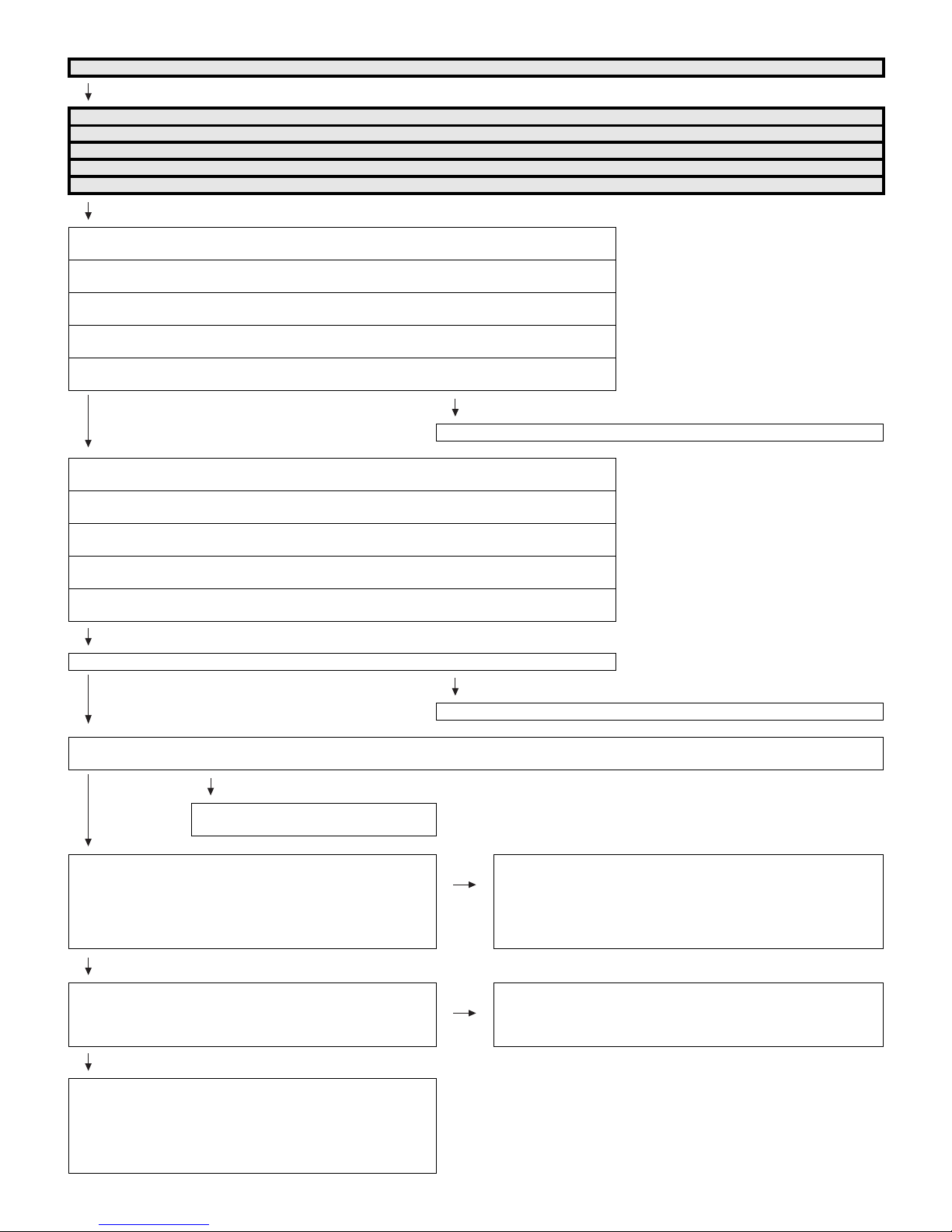
PRO-60/70X5FD
No audio (4)
INPUT-1 No audio (HDMI connected)
INPUT-2 No audio (HDMI connected)
INPUT-3 No audio (HDMI connected)
INPUT-4 No audio (HDMI connected)
INPUT-5 No audio (HDMI connected)
[INPUT-1 input]
Is INPUT-1 selected on the input select menu screen?
[INPUT-2 input]
Is INPUT-2 selected on the input select menu screen?
[INPUT-3 input]
Is INPUT-3 selected on the input select menu screen?
[INPUT-4 input]
Is INPUT-4 selected on the input select menu screen?
[INPUT-5 input]
Is INPUT-5 selected on the input select menu screen?
Refer to “: No external input video [INPUT-1/2/3/4/5]”.
YES
[INPUT-1 input]
If no video appears, refer to “No external input video (HDMI) [INPUT-1]”.
[INPUT-2 input]
If no video appears, refer to “No external input video (HDMI) [INPUT-2]”.
[INPUT-3 input]
If no video appears, refer to “No external input video (HDMI) [INPUT-3]”.
[INPUT-4 input]
If no video appears, refer to “No external input video (HDMI) [INPUT-4]”.
[INPUT-5 input]
If no video appears, refer to “No external input video (HDMI) [INPUT-5]”.
NO
Is the audio output selected for “VARIABLE” on the menu screen?
NO
YES
Does the digital audio signal come from pins (Y31/Y30/V27) (CPU_AOBK/AOLRCK/AOSDATA0) of IC3303 (CPU) to pin (8/9/7) (SP_BCLK/
SP_LRCLK/SP_DATA) of IC2701 (Audio DSP)?
NO
Check the line between IC3303 and
IC2701, and their peripheral circuits.
YES
• About the L/R Speakers.
Does the digital audio signal come from pins (47/43/44/45) of
IC2701 (Audio DSP) to pin (5/8/7/6) of IC2703 (AMP for L/R)?
• About the Subwoofer speaker.
Does the digital audio signal come from pins (47/43/44/46) of
IC2701 (Audio DSP) to pin (5/8/7/6) of IC2702 (AMP for SW)?
YES
• About the L/R Speakers.
Is the audio output from IC2703 as specified?
• About the Subwoofer Speaker.
IS the audio output from IC2702 as specified?
YES
• About the L/R Speakers.
Check the connector (P2701) L/R speakers and their peripheral
circuits.
• About the Subwoofer Speaker.
Check the connector (P2702), subwoofer speaker and their
peripheral.
Set the audio output to “FIXED”.
NO Check IC2701 and its peripheral circuits. (X2701, etc.).
NO • About the L/R Speakers.
Check IC2703 and its peripheral circuits.
• About the Subwoofer Speaker.
Check IC2702 and its peripheral circuits.
6 – 19
Page 69
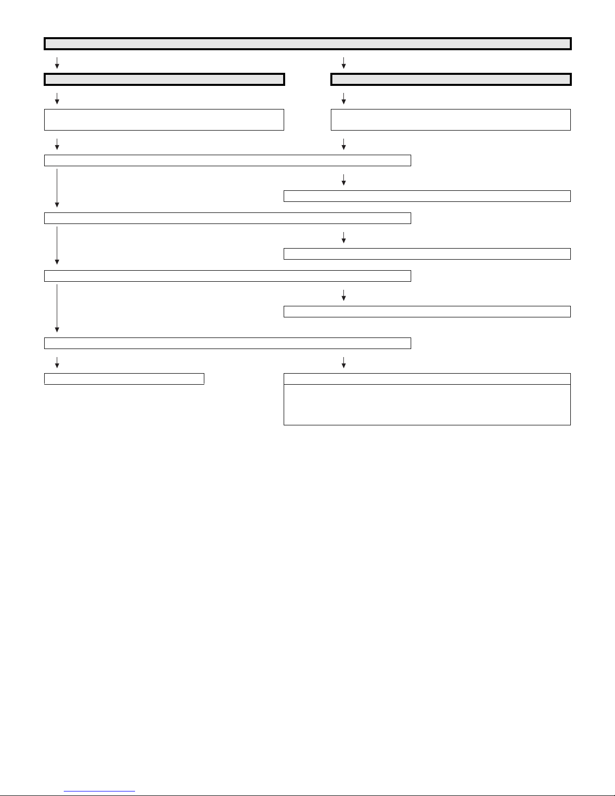
PRO-60/70X5FD
No audio signal at Digital Audio Output terminal (Analog sound heard)
No INPUT-1/2/3/4/5 (HDMI) audio. No audio at digital broadcast signal reception.
If no video appears, refer to “No external input video (HDMI)
[INPUT-1/2/3/4/5]”.
Is there the SPDIF signal output (CPU_ASPDIF) at pin (AA31) of IC3303 (CPU)?
Check the IC3303 and its peripheral circuits.
YES
Is there the SPDIF signal (OPT_OUT) input at pin (2) of IC503 (SPDIF BUFFER & SPDIF-MUTE)?
Check the line between IC3303 and IC503.
YES
Is there the MUTE signal input at pin (1) of IC503? (usual: High, Mute: Low)
Check the AUDIO_MUTE and their peripheral circuits (Q505, etc.).
YES
Is there the SPDIF signal input at pin (1) of D527 (OPTICAL OUTPUT)?
YES NO
Check the speakers and the optical cable. Check D527 and its peripheral circuits.
No optical output under the following conditions as per HDMI requirements.
* Audio contents protected.
* Audio frequency beyond 48kHz.
* Audio bit length beyond 16bits.
If no video appears, refer to “No video at digital broadcast signal
reception”.
NO
NO
NO
6 – 20
Page 70
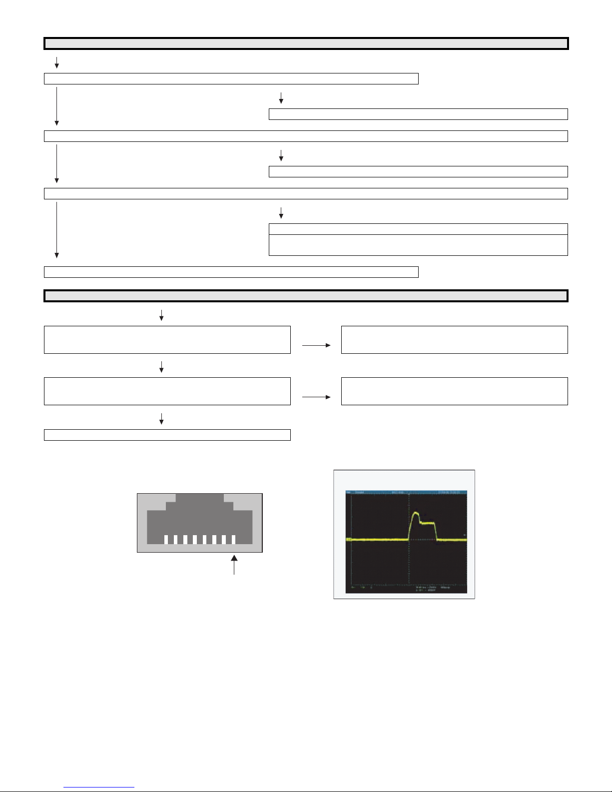
PRO-60/70X5FD
No monitor audio output
Is the audio output from the monitor set at “VARIABLE” or “FIXED” on the menu screen?
NO
Check IC3303 (CPU) and its peripheral circuits.
YES
Are there the audio signal outputs at pins (AJ31) (HP_MON_L) and (AJ32) (HP_MON_R) of IC3303 (CPU)?
NO
Check IC3303 (CPU) and its peripheral circuits.
YES
Does the audio signal come from pins (2) (MONI_HP_L) and (11) (MONI_HP_R) of IC2704 (Line-out Amplifier) to pins (3) (L) and (2) (R) of J504?
NO
Check the line between IC2704 and J504 and their peripheral circuits.
YES
Check the connector (J504) and their peripheral circuits, and speakers and the Cable.
Check the AUDIO_MUTE and HP_MUTE lines and its peripheral circuits (Q506,
Q510, D2711, etc.).
No connect network
Does the signal come to 1pin of LAN-jack J9501?
(see fig-1, fig-2)
NO
Does the signal come to AD32 pin of IC3303?
(see fig-2)
NO
Check IC3303 and its peripheral circuits.
LAN-jack J9501fig-1
YES Check the interface device and peripheral circuits.
(power-LED of hub, LINK-LED of hub)
YES Check the line between J9501 and IC3303.
Check the LAN-jack J9501.
fig-2
1pin
6 – 21
Page 71

PRO-60/70X5FD
PRO60X5FD
CHAPTER 7. MAJOR IC INFORMATIONS
Service Manual
[1] MAJOR IC INFORMATIONS
1. MAJOR IC INFORMATIONS
1.1. IC1504 (VHiSii9387+-1Q)
This IC is 5 input and 1 output HDMI port processor.
The TMDS cores run at 2.25Gbps. (Supports video resolutions up to 1080p, 60Hz, 12bit.)
The adaptive equalizer provides long cable support.
This IC has been pre-programmed with HDCP keys.
EDID and DDC support for 5 HDMI/DVI ports and 1 VGA port. (This IC includes 512-byte NVRAM and 256-byte SRAM for 5 HDMI ports and 128-byte
SRAM for VGA port.)
This IC supports the mandatory and several optional 3D formats described in the HDMI 1.4 Specification.
“Audio Return Channel” and “HDMI Ethernet Channel” support for one receiver port.
When changing this IC, please write EDID (how to write EDID is shown in Chapter 5 and section 10.1).
1.2. IC2001 (RH-iXD241WJNCQ)
The monitor microprocessor is intended to communicate with the main microprocessor and to operate the system.
It also controls power of the entire system.
1.3. IC2702, IC2703 (VHiYDA164BZ-1Y)
The Class-D type digital audio power amplifier YDA164BZ gives maximum continuous output of 10 W/ch or woofer output 15W.
1.4. IC3303 (RH-iXD220WJQZQ)
This LSI is FULL HIGH-DEFINITION 1080P DIGITAL TV SYSTEM-ON-A-CHIP.
It combines a transport de-multiplexer, a high definition video decoder, an AC3 audio decoder, a four-link LVDS transmitter, a V-by-One transmitter,
and an NTSC/PAL/SECAM TV decoder with a 3D comb filter (NTSC/PAL).
It supports Full-HD MPEG1/2/4/DiviX/VC1/RM/H.264/AVS video decoder standards, and JPEG.
Audio support includes a BTSC and a Dolby AC3/MPEG-2 Layer 1, 2, audio decoder.
A SPDIF output and a pair of analog outputs (L-R) are provided.
The LSI incorporates a complete ARM11-based microprocessor subsystem including caches with bridging to memory and a local bus, where external
peripherals can be attached.
Integrated peripherals include two USB 2.0, three UARTs, counter/timers and GPIO controllers.
1.5. IC3501, IC3502 (RH-iXD227WJQZQ)
These are 2G-bit (128M x 16bit) DDR3-1333 synchronous DRAM.
1.6. IC8401 (RH-iXD287WJQZQ)
The 2G-bit NAND flash memory device stores the main CPU program.
1.7. IC8455 (VHiBR24S64F-1Y)
This is 64k-bit EEPROM device including the user setting.
1.8. IC506 (VHiM3221EiP-1Y)
This IC is a high speed, single-channel RS-232 transceiver interface device that operates from a single 3.3V power supply.
The device provides the electrical interface between an asynchronous communication controller and the serial-port connector.
This device operate at data signaling rates up to 460kbit/s.
All RS-232 (Tout and Rin) and CMOS (Tin and Rout) inputs and outputs are protected against electrostatic discharge (up to +/- 15kV ESD protection).
1.9. IC2704 (VHiAK4201EU-1Y)
This IC is audio amplifier for line-out/head-phone.
1.10. IC2701 (VHiYSS951VZ-1Y)
Audio DSP (YSS951VZ) has digital audio adjustment function (for example, PEQ, bass/treble, balance, bass enhancer, etc.) and adjusts TVs audio
quality.
1.11. IC4405 (VHiMT5112EE-1Q)
This IC is a demodulator for digital terrestrial HDTV(8VSB) and digital CATV(64/256QAM).
It is compliant with ATSC A/53, SCTE DVS-031, and ITU J.83 Annex B standards.
7 – 1
Page 72

PRO-60/70X5FD
1.12. IC9505 (VHiPD720114-1Q)
This IC is a USB hub controller.
It has one upstream port and four downstream ports,
7 – 2
Page 73
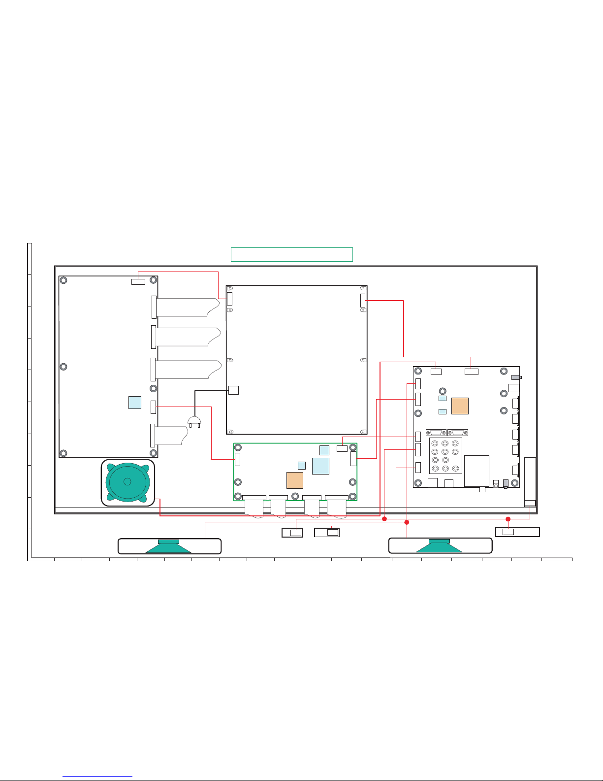
PRO-60/70X5FD
8 – 1
PRO60X5FD
Service Manual
CHAPTER 8. OVERALL WIRING/SYSTEM BLOCK DIAGRAM
[1] OVERALL WIRING DIAGRAM (PRO-60X5FD)
1
2
10976543 8
J
A
B
C
D
E
F
G
H
I
1311 191816151412 17
[IR]
3D IR EMITTER Unit
RUNTKA819WJQZ
1
180
Full-HD Panel (1920×1080)
60”: R1LK600D3GW60Z
MAIN Unit
DKEYMF733FM21
[RC]
1
15
1
5
[SP]
[LW]
[PD]
POWER Unit
RDENCA418WJQZ
[PL]
13
[AC]
TUNER
HDMIHDMI
24
1
12
[SB]
WOOFER:
RSP-ZA513WJQZ
LCD CONTROL Unit
RUNTK4908TPZA
1
6
[UB]
HDMI
124
[PD]
[PL]
WiFi Unit
RUNTKA810WJQZ
R/C OPC Unit
DUNTKF909FM01
Lch:
RSP-ZA512WJZZ
HDMI
USB
USB
ETHER
NET
[LW]
1
41
Rch:
RSP-ZA512WJZZ
1
41
1
4
HDMI
1
13
14
14
KEY Unit
DUNTKF800FM50
[UB]
16
13
[RC]
17
[LA]
1
18
LED DRIVE Unit
RUNTKA841WJZZ
118
[LA]
[LB]
[LB]
1 1
FFC
QCNWN2762TPZZ
QCNWN2763TPZZ
QCNWN2764TPZZ
QCNWN2765TPZZ
1
8
0
1
80
1
80
1
80
FFC(CTL_Source PWB)
64pin: QCNWN2734TPZZ
80pin: QCNWN2733TPZZ
[KM]
1
13
80
64 64
Page 74
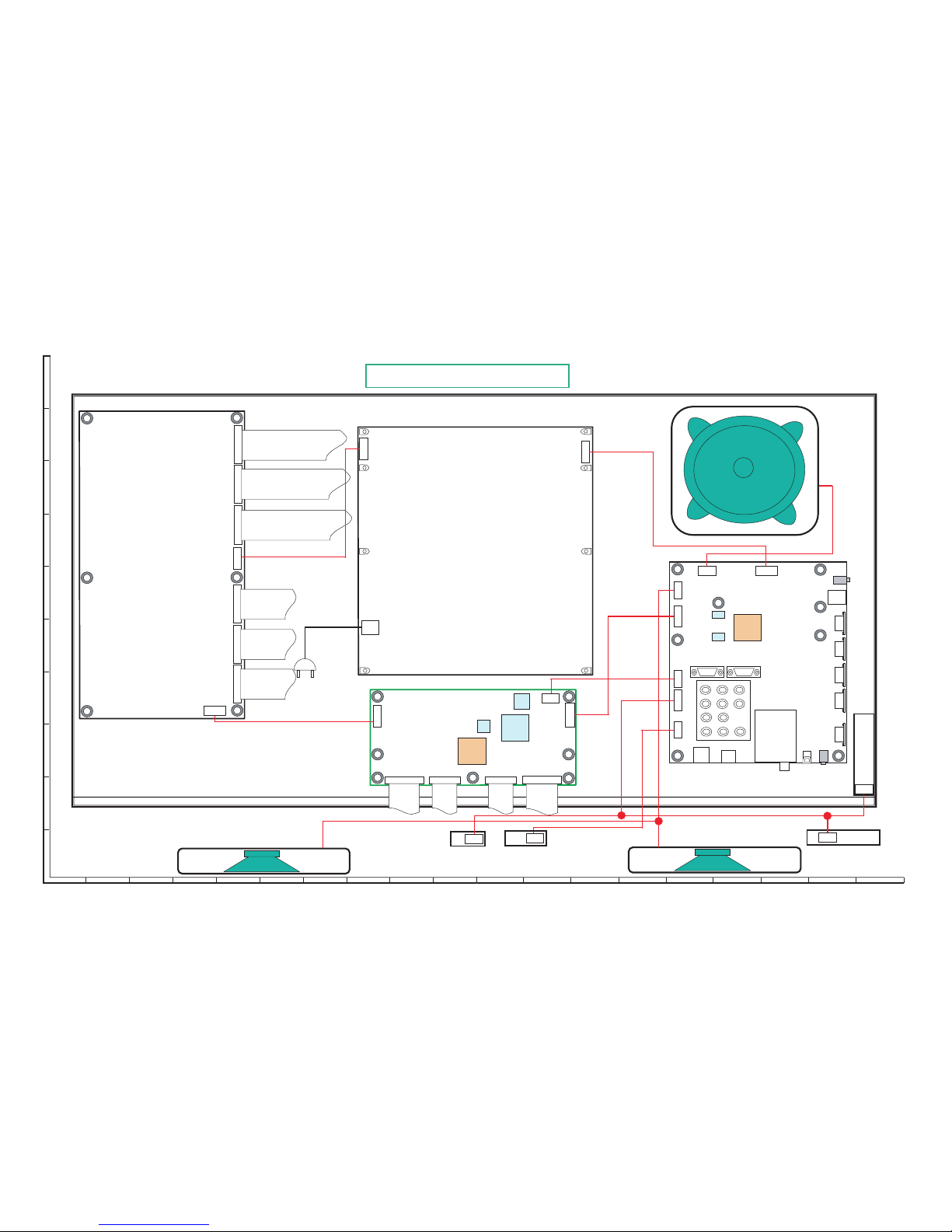
PRO-60/70X5FD
8 – 2
[2] OVERALL WIRING DIAGRAM (PRO-70X5FD)
1
23
1097654
8
J
A
B
C
D
E
F
G
H
I
1311 191816151412 17
[IR]
3D IR EMITTER Unit
RUNTKA819WJQZ
180
180
Full-HD Panel (1920×1080)
70": R1LK695D3GW10Z
MAIN Unit
DKEYMF733FM20
[RC]
1
15
1
5
[SP]
[LW]
[PD]
POWER Unit
RDENCA446WJQZ
[PL]
13
[AC]
TUNER
HDMIHDMI
24
1
12
[SB]
WOOFER: RSP-ZA513WJQZ
LCD CONTROL Unit
RUNTK4908TPZF
1
6
[UB]
HDMI
124
[PD]
[PL]
WiFi Unit
RUNTKA810WJQZ
R/C OPC Unit
DUNTKF909FM01
Lch:
RSP-ZA512WJZZ
HDMI
USB
USB
ETHER
NET
[LW]
1
41
Rch:
RSP-ZA512WJZZ
1
41
1
4
HDMI
1
13
14
14
KEY Unit
DUNTKF800FM50
[UB]
16
13
[RC]
17
[LA]
1
18
LED DRIVE Unit
RUNTKA838WJZZ
113
[LB]
[LB]
164 164
1
80
1
80
1
80
1
80
FFC(CTL_Source PWB)
64pin: QPWBM1087TPZZ
80pin: QPWBM1007TPZZ
[KM]
[LA]
1
18
1
80
1
80
Page 75
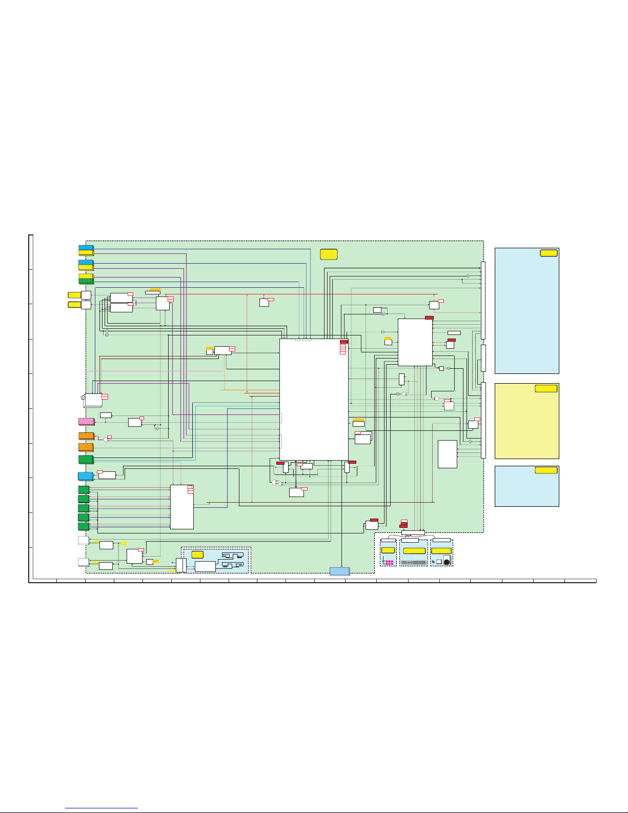
PRO-60/70X5FD
8 – 3
[3] SYSTEM BLOCK DIAGRAM
1
23
1097654
8
J
A
B
C
D
E
F
G
H
I
1311 191816151412 17
IC3303
MT5395(FHD)
H.264 / VC-1
DigitalAV decode & Main CPU
SPI_FLASH
/NANDFlash
LVDSOUT
USB_0
Audioin
DTV/SPDIF
I2C_1
RESET
UART-TXD0
RGBin(AK17)
DDC_I2C_1
HDMI_1
CVBS
I2C_0
MAIN
SIF
PS_ON
BU5V
AC_DET
POWERCIRCUIT
MAIN
D5.6V
D5V
U5V
D3.3V
M1.8V
D1.5V
D1.1V
INPUT
7
UR13V
BackUp
BU+3.3V
IC2703
SPAMP(2CH)
YDA164
HP/MONI_L/R(PWM)
I2S(SDATA/LRCK/SCLK)
Disclete
Mute
PC/HDMI_LR
RGB/HDMI
Audio
(MiniPlug)
[SP]
P2701
EXT-SP
SPEAKER
OPTICAL
OUT
OPT_OUT
AUDIO_MUTE
27.000MHz
X3301
X'tal
INPUT
1
INPUT
9
RFIN
UART_CPUTO232C,UART_232CTOCPU
TU_DEMOD_SCL/SDA
(400KHz3.3V)
J9502
USB
IC506
RS232CTxRx
M3221EIP
RS-232C
+3.3V
No.9pin RC Passthrough
IC8455
EEPROM
64kbit
+3.3V
INPUT
8
HDMI1
(ARC)
INPUT
2
INPUT
2/9
D-SUB
RGB
Audioout
IC3501
DDR3(1333M)
2Gbi t
UART-2
I2C_0
CVBS2_IN
CVBS2_IN_L/R
D_IF-/+
COMP1_IN_L/R
U5V
IC9502
PowerSW
AP2151
OFL1
PWM_0
IC8401
NANDFLASH
2Gbit
+3.3V
+3.3V
+1.5V
+1.2V
+1.1V
[LW]P2601 (41p)
RGBHV(AK14,AJ14)
IC1504
HDMI-SW
SII9387
DDC_3
HDMI_3
DDC_4
HDMI_4
+3.3V
AudioOut
(MiniPlug)
TUNER_I2C
PWM_1
HDMI_CEC
IC3502
DDR3(1333M)
2Gbit
PNL_POW
S13V
I/O
Component
COMP1_Y/Pb/Pr
HDMI2
HDMI3
HDMI4
INPUT
3
DDC_2
HDMI_2
DDC_1
HDMI_1
IC2601
Spliter
HC2G66DP
I2C_0(400KHz)
ONDD8㨪15
N_TUN_RST
IC2701
DSP
(YSS951)
I2C_0(400KHz)
IC2702
WooferAMP(0.1CH)
YDA164
AMP_DATA_LR
AMP_DATA_SW
AMP_LRCK/BCLK/MCLK
[SP]
P2702
EXT-SP
Woofer
+3.3V
+1.8V
+13V
+13V
USB_1
J9501
Ethernet
UART-TXD1
+5V
[RC] P2001(15p)
RC,OPC
PNL_POW
AC_DET
PC/HDMI_LR
CVBS2_IN_L/R
COMP_IN_L/R
PC_VSYNC/HSYNC
PC_R/G/B
PC_VSYNC/HSYNC
PC_R/G/B
OPT_OUT
HP/MONI_L/R
SIF
(400KHz3.3V)
24.576MHz
X2701Xtal
VON
PNL_WP
+5V
(100KHz3.3V)I2C_1
IC9611
Spliter
HC2G66DP
PNL_I2C_EN
L/R_REF
DDC_0
HDMI_0
T-CON
LED_Drive
POWER Unit
UR13V
I2C_1(100KHz)
PNL_I2C_EN
AUDIO_MUTE
+3.3V
+3.3V
+1.2V
N_PER_RST
N_AMP_PROTECT
SP_MUTE
IC503
AUDIO_MUTE
INPUT
4
J9504
USB
IC9503
PowerSW
AP2181
+5V
IC9505
USB2.0Hub
Controller
PD720114
X9502
Xtal
30MHz
BU+3.3V
1.5A
0.5A
SIF
TU1105
Analog/
Digital
SiTuner
CVBS
LR
LR
Component
CVBS
LR
CVBS1_IN
CVBS1_IN_L/R
CVBS1_IN_L/R
INPUT
6
CVBS_Out
BU+3.3V
AMP_HOPP
N_PER_RST
N_AMP_PROTECT
IC2704
HP-AMP
AK4201EU
+5V
VSYNC
LR_PULSE
CVBS
IC4405
ATSCDemod
MT5112EE
TU_SCL/SDA
X4402
Xtal
25MHz
DEMOD_RST
DEMOD_TSCLK/SYNC/VAL/DATA0
+3.3V
+1.2V
N_TUN_RST
I2C_2
OFL2
IC9610
Spliter
HC2G66DP
+3.3V
PNL12V
I2C_1( 100KHz)
AUDIO_MUTE
ATSC_IF_AG
+1.5V
+5V
+3.3V
HDMI_CEC
IC2003
Buffer
LCX125FT
BU+3.3V
HDMICECI
HDMICECOU
Thermister
IC2001
R8C/36C
IXD241WJ
SUBMCU
LAMP_ERR
I/O
I/O
AC_DET
I/O
THERMO
A/D
I/O
I/O
FL2001
Xtal
20MHz
STB
I/O
UART
BU+3.3V
UCOM_RST
IC2001
Reset
N_SRESET
I2C
EEPROM_SCL/SDA
IC2004
EEPROM
2kbit
BU+3.3V
DET_PNL12V
WP
SMPOW
PS_O
SMPOWHOLD
I/O
I/O
I/O
AUDIO_MUTE(=N_MUTE_A_ALL)
HDMI_CEC_IN
HDMI_CEC_OUT
UCOM_MODE
MODE
RESET
OR
I/O
I/O
I/O
I/O
CPU_TXD1_UCOM,CPU_RXD1_UCOM
N_SRESET
RESET
SMPOWHOLD
UART-RXD0
UART-RXD1
IC8451
Buffer
+3.3V
IC8452-1
Select
IC8452-2
Select
BU+3.3V
BU+3.3V
0
11
0
IC8452-3
Select
RC,OPC
RC
RC_CPU
A/D
0
1
GND
4
2
3
[RA] P103(7p)
3D IR
[IR] (6p)
PWM
1
6
3
2
4
5
12
7
I2C_READY
8
9
STB_CPU
RC
IR_PASS
AMP_MUTE
N_PER_RST
N_PER_RST
+5V
WOWLAN
WiFi
[UB]WiFi
P9501(6p)
(6p)
UNIT
[PL]PNL12V P2605(4p)
OFL1_FRCRST
[PD]POWER P9602(24p)
3
5
1
7
11
4
2
12
10
PWM2
GSPPWM1
N_PNL_EN
PNL_EN
+3.3V
+1.8V
HDMI5
INPUT
5
TACT KEY R/C, LED
[KM] P151(4p)
OPC
R/C
BU+5V
LED_WHITE,LED_BLUE
LED_WHITE(=LED_OPC),LED_BLUE(=LED_YOYAKU)
Page 76

PRO-60/70X5FD
8 – 4
— M E M O —
Page 77
PartsGuide
PRO-60/70X5FD
PARTS GUIDE
No. S81S7PR60X5FD
LCD COLOR TELEVISION
PRO-60X5FD
[1] PRINTED WIRING BOARD
ASSEMBLIES (PRO-60X5FD)
[2] PRINTED WIRING BOARD
ASSEMBLIES (PRO-70X5FD)
[3] LCD PANEL MODULE UNIT
MODELS
CONTENTS
PRO-70X5FD
[5] CABINET PARTS (PRO-70X5FD)
[6] SUPPLIED ACCESSORIES/
PACKING PARTS (PRO-60X5FD)
[7] SUPPLIED ACCESSORIES/
PACKING PARTS (PRO-70X5FD)
[4] CABINET PARTS (PRO-60X5FD)
Parts marked with " " are important for maintaining the safety of the set. Be sure to replace these
parts with specified ones for maintaining the safety and performance of the set.
[8] SERVICE JIGS
(USE FOR SERVICING)
This document has been published to be used
for after sales service only.
The contents are subject to change without notice.
Page 78
PRO-60/70X5FD
NO. PARTS CODE
PRICE
RANK
NEW
MARK
PAR T
DELIVERY
[1] PRINTED WIRING BOARD ASSEMBLIES (PRO-60X5FD)
N DKEYMF733FM21 N X MAIN Unit
N DUNTKF909FM01 N X R/C OPC Unit
N DUNTKF800FM50 N X KEY Unit
N RUNTKA810WJQZ X WiFi Unit
N RUNTKA819WJQZ X 3D IR EMITTER Unit
!
N RDENCA418WJQZ N X POWER Unit
N RUNTKA841WJZZ N X LED DRIVE Unit
N RUNTK4908TPZA N X LCD CONTROL Unit
[2] PRINTED WIRING BOARD ASSEMBLIES (PRO-70X5FD)
N DKEYMF733FM20 N X MAIN Unit
N DUNTKF909FM01 N X R/C OPC Unit
N DUNTKF800FM50 N X KEY Unit
N RUNTKA810WJQZ X WiFi Unit
N RUNTKA819WJQZ X 3D IR EMITTER Unit
!
N RDENCA446WJQZ N X POWER Unit
N RUNTKA838WJZZ N X LED DRIVE Unit
N RUNTK4908TPZF N X LCD CONTROL Unit
[3] LCD PANEL MODULE UNIT
N R1LK600D3GW60Z N X 60" LCD Panel Module Unit (LK600D3GW60Z) (PRO-60X5FD)
N R1LK695D3GW10Z N X 70" LCD Panel Module Unit (LK695D3GW10Z) (PRO-70X5FD)
DESCRIPTION
2
Page 79
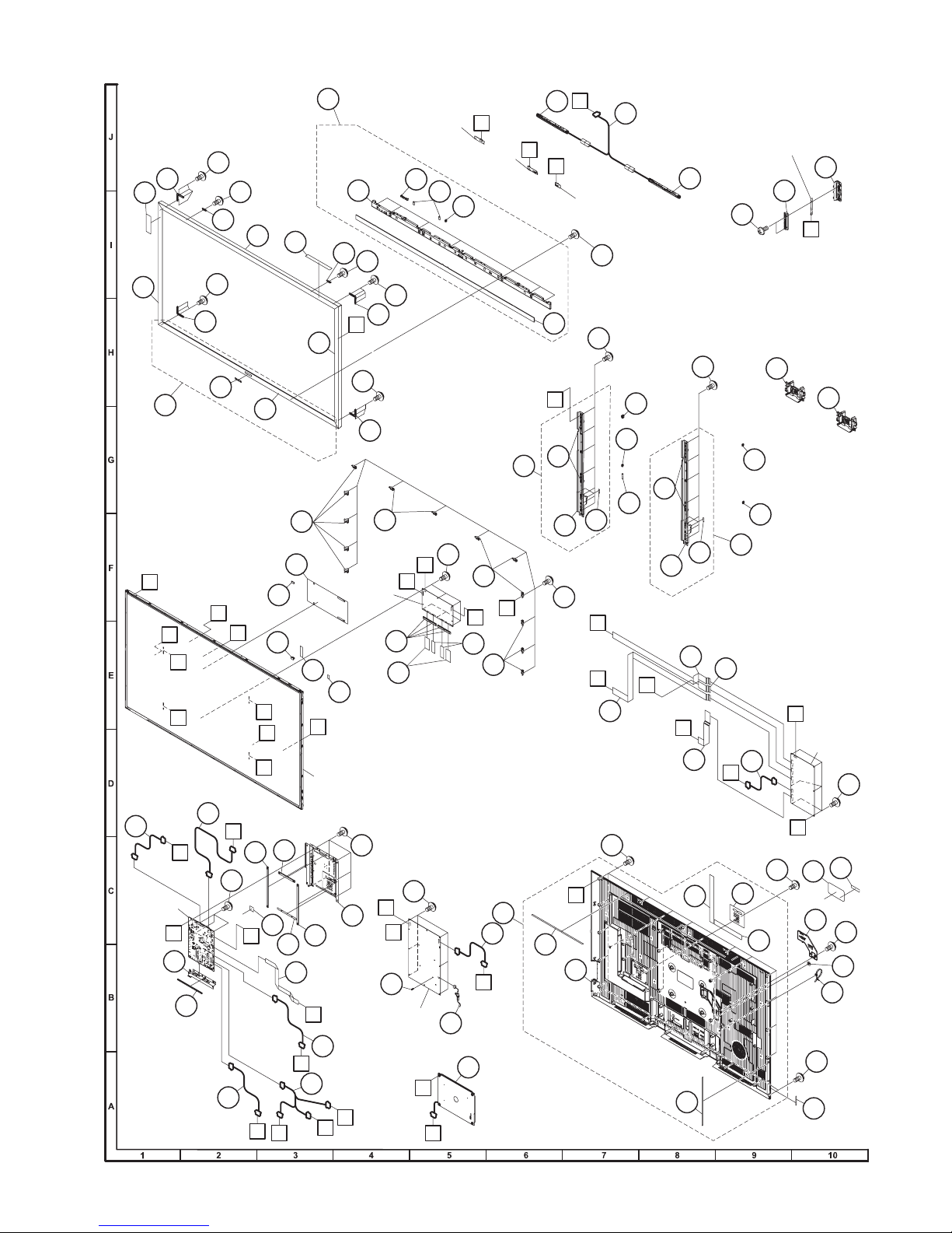
[4] CABINET PARTS (PRO-60X5FD)
PRO-60/70X5FD
22
9
21
3
A
D
50
MAIN Unit
32
D
a
b
PD
41
22
27
24
24
3-2
2
2-4
38
14
2-5
15
55
LB
RC
11
LA
WiFi
Unit
11
51
UB
4
G
1
R/C OPC
Unit
24
23
19
30
3-1
11
48
35
E
B
33
d
C
e
SB
40
39
38
46
SP
45
53
PL
25
UB
RC
2-1
23
24
G
20
24
LCD
CONTROL
Unit
42
47
F
60" LCD
Panel Module Unit
61
43
39
LW
49
26
KM
IR
2-2
24
22
22
11
PL
LW
60
54
61
PD
B
44
POWER
Unit
C
SB
29
IR
2-3
E
4-2
4-1
13
1-5
1-1
SP
28
3D IR EMITTER
Unit
24
61
34
37
36
4-3
a
b
58
16
A
KEY Unit
29
17
61
4-2
4-3
4-1
56
57
d
e
59
1-2
1-6
LB
31
37
37
4
52
18
1-4
1-3
10
LA
LA
F
7
KM
31
LED Drive
Unit
38
62
8
6
18
5
12
18
63
3
Page 80
PRO-60/70X5FD
NO. PARTS CODE
[4] CABINET PARTS (PRO-60X5FD)
1 CCABBB990WJ31 N X Rear Cabinet Ass'y
1-1 Not available - N - Rear Cabinet
1-2 HiNDPE268WJSA N X Terminal Indicator (Side)
1-3 HiNDPE365WJSA N X Terminal Indicator (Bottom)
1-4 HiNDPE378WJSA N X Terminal Indicator (Back)
1-5 PSPAHC171WJZZ X Himeron, x3
1-6 PSPAHC497WJZZ N X Himeron
2 CBDYFA042WJ31 X Bottom Body Ass'y
2-1 Not available - N - Bottom Body
2-2 GCOVAE187WJ3A N X R/C OPC Cover
2-3 HDECQB634WJ3A N X Front Decoration Plate
2-4 LHLDWA175WJUZ AC J Wire Holder, x2
2-5 LHLDWA289WJKZ AC J Wire Holder
3 CDECEA035WJ31 N X Decoration Frame Ass'y (Bottom)
3-1 Not available - - Decoration Frame (Bottom)
3-2 Not available - - ELITE Badge
4 CANGKD340WJ31 N X Center Angle Ass'y, x2
4-1 Not available - N - Center Angle
4-2 Not available - - VESA Shaft
4-3 PSPAHC502WJZZ N X Himeron, x4
5 GCOVAC576WJKZ AC J VESA Hole Cover, x4
6 GCOVAE121WJ2A N X AC Cord Cover
7 GCOVAE188WJ3A N X Key Button Cover
8 HiNDPE269WJSA N X Model Label (108811112~108811143)
8 HiNDPE462WJSA N X Model Label (108811144~)
9 HiNDPE299WJZZ N X Energy Label
10 JBTN-A937WJ3A N X Key Button
11 LANGKD337WJ3W N X Fixing Metal Angle, x13
12 LHLDWA303WJKA AE J Cable Tie
13 LX-BZA207WJF7 AA J Screw, x13
!
14 QACCDA089WJPZ N X AC Cord
15 RSP-ZA513WJQZ BC J Speaker (Woofer)
16 XBPS830P06WS0 AA J Screw, x18
17 XEBS830P08000 AA J Screw, x2
18 XEBS830P12000 AA J Screw, x10
19 HDECEA034WJ3A X Decoration Frame (Top)
20 HDECEA036WJ3A X Decoration Frame (R)
21 HDECEA037WJ3A X Decoration Frame (L)
22 LANGKD334WJ3W X Corner Angle, x4
23 LHLDZB797WJ3Z X Fixing Hook, x2
24 LX-BZA202WJF8 AA J Screw, x23
25 QCNW-L615WJQZ X Connecting Cord (UB)
26 QCNW-M169WJQZ N X Connecting Cord (RC)
27 QCNW-M170WJQZ N X Connecting Cord (SB)
28 QCNW-M171WJQZ N X Connecting Cord (SP)
29 RSP-ZA512WJQZ BC J Speaker (L/R)
30 TLABZC953WJZZ X License Label
31 GCOVAE189WJ3A X Bottom Cover, x2
32 LANGKD292WJ3A N X Terminal Angle (Bottom)
33 LHLDWA124WJKZ AC J Wire Holder
34 LHLDWA151WJKZ AB J Wire Holder
35 LHLDWA175WJUZ AC J Wire Holder
36 LHLDWA176WJUZ AC J Wire Holder
37 LHLDWA289WJKZ AC J Wire Holder, x3
38 LX-BZA207WJF7 AA J Screw, x15
39 PMLT-A678WJQZ X Gasket, x2
40 PMLT-A679WJQZ X Gasket
41 PMLT-A680WJQZ X Gasket
42 PMLT-A685WJQZ N X Gasket
43 PSLDMB771WJ3A N X Shield (MAIN Unit)
44 PSPANA044WJKZ AB J PWB Spacer
45 PSPAZC740WJZZ X Spacer
46 PSPAZC741WJKZ X Spacer (MAIN Unit)
47 PSPAZC782WJKZ N X
48 PZETKA631WJKZ N X POWER Insulation Sheet
49 QCNW-L587WJQZ AE J Connecting Cord (PL)
50 QCNW-L608WJQZ AM J Connecting Cord (PD)
51 QCNW-L611WJQZ N X Connecting Cord (LA)
52 QCNW-L612WJQZ N X Connecting Cord (LB)
53 QCNW-L629WJQZ AY N J Connecting Cord (LW)
54 QCNWN2733TPZZ AF J FFC (80pin), x2
55 QCNWN2734TPZZ AF J FFC (64pin), x2
56 QCNWN2762TPZZ N X FFC
57 QCNWN2763TPZZ N X FFC
58 QCNWN2764TPZZ N X FFC
59 QCNWN2765TPZZ N X FFC
60 RCORFA061WJZZ AG J Ferrite Core, x4
61 XBPS830P06WS0 AA J Screw, x25
62 TLABNB037WJZZ X Serial No. Label (Back)
63 Not available - N - Serial No. Label (Side)
PRICE
RANK
NEW
MARK
PAR T
DELIVERY
DESCRIPTION
Spacer (LCD CONTROL Unit)
4
Page 81
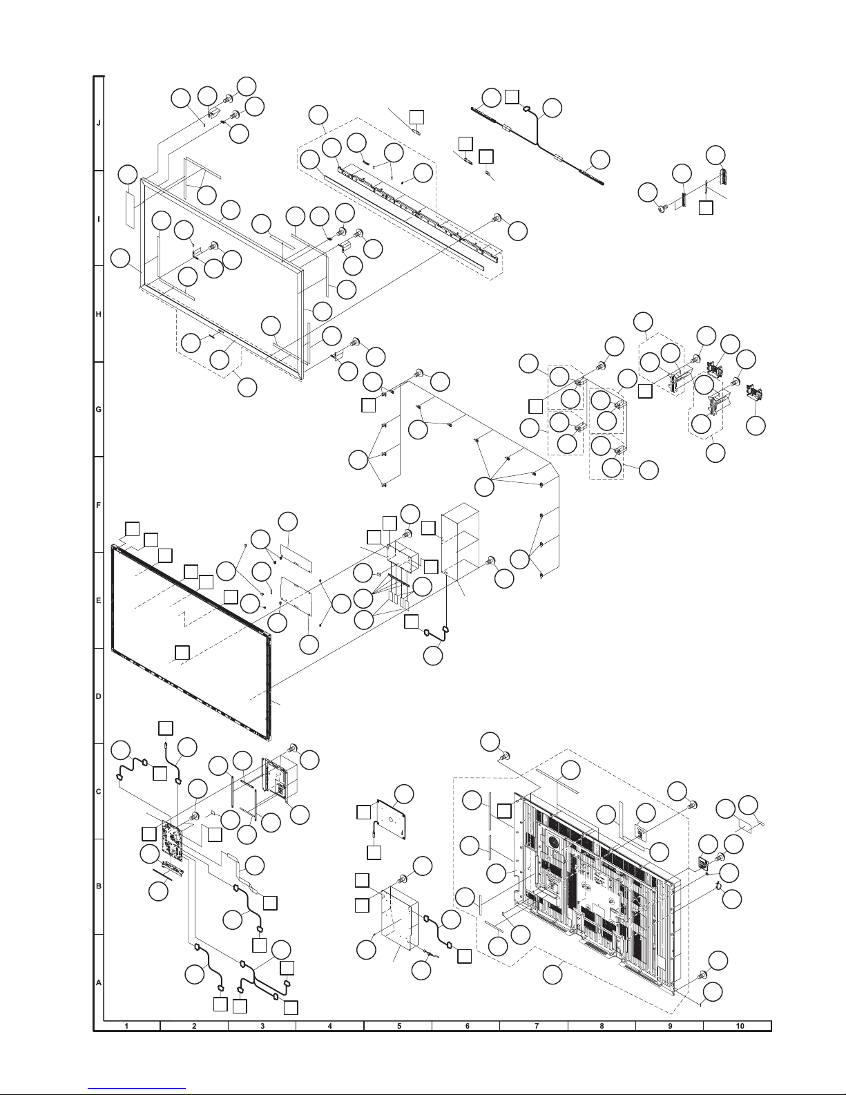
[5] CABINET PARTS (PRO-70X5FD)
24
22
21
25
9
61
61
25
61
3-2
22
24
23
2-3
19
30
24
61
3-1
3
2
2-1
2361
20
61
R/C OPC Unit
2-2
24
24
22
61
24
22
11
G
11
2-4
RA
2-5
11
WiFi
Unit
13
29
UB
IR
11
SP
28
3D IR EMITTER
Unit
24
4
4-1
E
4-1
4
4-2
4-2
29
4-1
4-1
4-2
57
4-2
PRO-60/70X5FD
7
10
17
33
33-2
33-1
4
F
4
KM
57
33-2
33-1
KEY Unit
31
57
31
33
49
MAIN
Unit
PL
LW
SB
POWER
Unit
15
38
LB
LA
LB
55
53
57
14
38
LED DRIVE Unit
16
1-5
A
1-7
1-1
1-8
48
1-8
LA
11
1-9
1-6
18
58
1-4
1-2
1-3
1
8
18
6
5
12
18
59
43
37
51
35
36
PL
34
39
LW
27
47
LCD
CONTROL
Unit
45
56
37
54
46
70" LCD
Panel Module Unit
57
42
PD
KM
IR
C
B
60
G
A
C
34
D
E
B
F
SB
52
PD
38
D
32
41
26
SP
39
UB
40
44
50
RA
5
Page 82
PRO-60/70X5FD
NO. PARTS CODE
[5] CABINET PARTS (PRO-70X5FD)
1 CCABBB991WJ31 N X Rear Cabinet Ass'y
1-1 Not available - N - Rear Cabinet
1-2 HiNDPE268WJSA X Terminal Indicator (Side)
1-3 HiNDPE365WJSA N X Terminal Indicator (Bottom)
1-4 HiNDPE378WJSA N X Terminal Indicator (Back)
1-5 PSPAHC168WJZZ N X Himeron
1-6 PSPAHC171WJZZ N X Himeron, x2
1-7 PSPAHC504WJZZ N X Himeron
1-8 PSPAHC505WJZZ N X Himeron, x2
1-9 PSPAHC502WJZZ N X Himeron
2 CBDYFA043WJ31 X Bottom Body Ass'y
2-1 Not available - N - Bottom Body
2-2 GCOVAE187WJ3A X R/C OPC Cover
2-3 HDECQB635WJ3A N X Front Decoration Plate
2-4 LHLDWA175WJUZ AC J Wire Holder, x2
2-5 LHLDWA289WJKZ AC J Wire Holder
3 CDECEA038WE31 N X Decoration Frame Ass'y (Bottom)
3-1 Not available - - Decoration Frame (Bottom)
3-2 Not available - - ELITE Badge
4 CANGKD289WJ31 X VESA Angle Ass'y, x4
4-1 Not available - N - VESA Angle
4-2 Not available - N - VESA Shaft
5 GCOVAC576WJKZ AC J VESA Hole Cover, x4
6 GCOVAE163WJ3A X AC Cord Cover
7 GCOVAE188WJ3A X Key Button Cover
8 HiNDPE270WJSA N X Model Label
9 HiNDPE298WJZZ N X Energy Label
10 JBTN-A937WJ3A X Key Button
11 LANGKD335WJ3W N X Fixing Metal Angle, x14
12 LHLDWA303WJKA AE J Cable Tie
13 LX-BZA207WJF7 AA J Screw, x14
!
14 QACCDA084WJPZ X AC Cord
15 RSP-ZA513WJQZ BC J Speaker (Woofer)
16 XBPS830P06WS0 AA J Screw, x21
17 XEBS830P08000 AA J Screw, x2
18 XEBS830P12000 AA J Screw, x10
19 HDECEA038WJ3A X Decoration Frame (Top)
20 HDECEA040WJ3A X Decoration Frame (R)
21 HDECEA041WJ3A X Decoration Frame (L)
22 LANGKD334WJ3W X Corner Angle, x4
23 LHLDZB803WJ3Z X Fixing Hook, x2
24 LX-BZA202WJF8 AA J Screw, 25
25 PSPAKA492WJKZ N X Spacer, x2
26 QCNW-M035WJQZ X Connecting Cord (UB)
27 QCNW-M173WJQZ N X Connecting Cord (RC)
28 QCNW-M175WJQZ N X Connecting Cord (SP)
29 RSP-ZA512WJQZ BC J Speaker (L/R)
30 TLABZC953WJZZ X License Label
31 GCOVAE189WJ3A X Bottom Cover, x2
32 LANGKD292WJ3A N X Terminal Angle (Bottom)
33 CANGKD339WJ31 N X Stand Angle Ass'y, x2
33-1 Not available - N - Stand Angle, x2
33-2 PSPAHC502WJZZ N X Himeron, x4
34 LHLDWA124WJKZ AC J Wire Holder, x3
35 LHLDWA151WJKZ AB J Wire Holder, x2
36 LHLDWA176WJUZ AC J Wire Holder
37 LHLDWA289WJKZ AC J Wire Holder, x3
38 LX-BZA207WJF7 AA J Screw, x14
39 PMLT-A678WJQZ X Gasket, x2
40 PMLT-A679WJQZ X Gasket
41 PMLT-A680WJQZ X Gasket
42 PSLDMB771WJ3A N X Shield (MAIN Unit)
43 PSPAZC740WJZZ X Spacer
44 PSPAZC741WJKZ X Spacer (MAIN Unit)
45 PSPAZC782WJKZ X
46 PZETKA625WJ3A N X POWER Insulation Sheet (L)
47 PZETKA646WJ3A N X POWER Insulation Sheet (S)
48 QCNW-L611WJQZ X Connecting Cord (LA)
49 QCNW-M029WJQZ N X Connecting Cord (PD)
50 QCNW-M031WJQZ X Connecting Cord (PL)
51 QCNW-M168WJQZ X Connecting Cord (LW)
52 QCNW-M174WJQZ N X Connecting Cord (SB)
53 QCNW-M316WJQZ N X Connecting Cord (LB)
54 QPWBM1007TPZZ AF J FFC (80pin), x2
55 QPWBM1087TPZZ X FFC (64pin), x2
56 RCORFA061WJZZ AG J Ferrite Core, x4
57 XBPS830P06WS0 AA J Screw, x39
58 TLABNB037WJZZ X Serial No. Label (Back)
59 Not available - N - Serial No. Label (Side)
60 PSPANA044WJKZ AB J PWB Spacer
61 PSPAHC168WJZZ N X Himeron, x8
PRICE
RANK
NEW
MARK
PAR T
DELIVERY
DESCRIPTION
Spacer (LCD CONTROL Unit)
6
Page 83
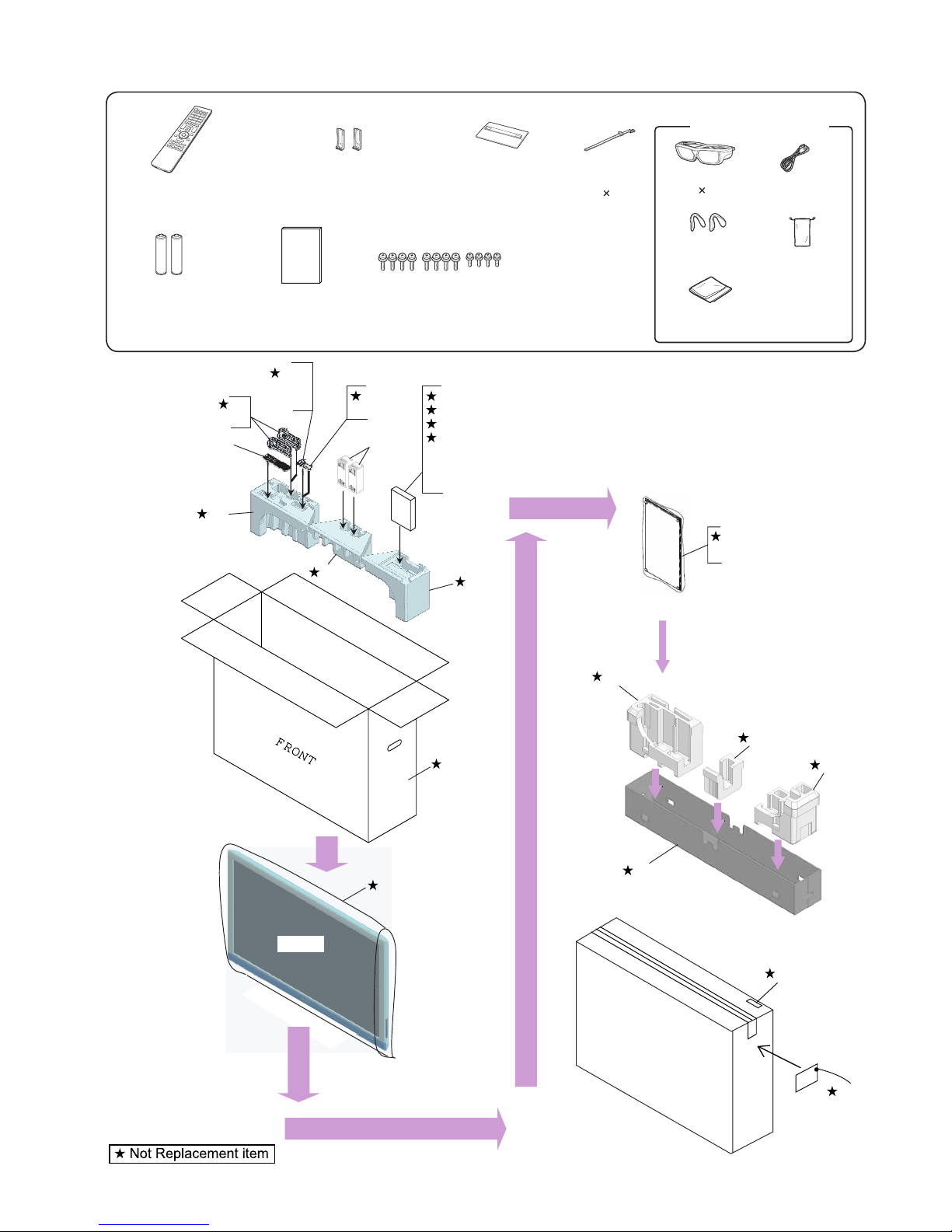
[6] SUPPLIED ACCESSORIES/PACKING PARTS (PRO-60X5FD)
PRO-60/70X5FD
X4
3D Glasses Accessories
X5
Remote control (x1)
X10
“AA” size battery (x2)
X9
Operation manual (x1)
S9
X1
X5
S4
X1 X2 X6
Stand support Ass'y (x2) Stand Base Ass'y (x1)
X7 Brochure (E)
X7 Brochure (F)
X3
Stand Screw Ass'y (x1)
X8 Guarantee card
S12
X6
X10
X3
S11
S6
S7
S8
X4
S13
X7
X8
X9
S4
S4
Cable tie
1)
(
3D Glasses
2)
(
Nose pad *1
(small ×2, large ×2)
Cleaning cloth
(×2)
S10
X2
USB cable*2
(×2)
Glasses case
(×2)
FRONT
S3
S1
S5
S5
S5
S2
S14
S14
7
Page 84
PRO-60/70X5FD
NO. PARTS CODE
PRICE
RANK
NEW
MARK
PAR T
DELIVERY
DESCRIPTION
[6] SUPPLIED ACCESSORIES/PACKING PARTS (PRO-60X5FD)
X1 CANGKD276WJ01 X Stand Support Ass'y, x2
X2 CDAi-A778WJ31 X Stand Base Ass'y
X3 CSAKKA011WJ01 X Stand Screw Ass'y
X4 AN-3DG20-EL N X 3D Glasses Accessories, x2
X5 RRMCGA937WJSA N X Remote Control
X6 LHLDWA303WJKA AE J Cable Clamp
X7 TCTLZA001WJZZ N X Brochure (E)
X7 TCTLZA002WJZZ N X Brochure (F)
X8 TGAN-B661WJZZ N X Guarantee Card
X9 TiNS-F205WJZZ N X Operation Manual
X10 Not available - - "AA" size battery, x2
S1 SPAKCG442WJZZ - N - Packing Case (NOT REPLACEMENT ITEM)
S2 SPAKCG443WJZZ - N - Packing Case (Bottom) (NOT REPLACEMENT ITEM)
S3 SPAKPB427WJZZ - - Wrapping Paper (NOT REPLACEMENT ITEM)
S4 SPAKXD445WJZZ - N - Packing Add. (Top) (NOT REPLACEMENT ITEM)
S5 SPAKXD446WJZZ - N - Packing Add. (Bottom) (NOT REPLACEMENT ITEM)
S6 SPAKFC160WJZZ - N - Outer Case (NOT REPLACEMENT ITEM)
S7 SPAKFC161WJZZ - N - Remocon Case (NOT REPLACEMENT ITEM)
S8 SPAKFC162WJZZ - N - Manual Cover (NOT REPLACEMENT ITEM)
S9 SPAKPB723WJZZ - N - Wrapping Paper (Support) (NOT REPLACEMENT ITEM)
S10 SPAKPB722WJZZ - N - Wrapping Paper (Stand) (NOT REPLACEMENT ITEM)
S11 SSAKKA011WJZZ - N - Polyethylene Bag (NOT REPLACEMENT ITEM)
S12 SSAKAA032WJZZ - - Polyethylene Bag (NOT REPLACEMENT ITEM)
S13 SSAKAA185WJZZ - N - Polyethylene Bag (NOT REPLACEMENT ITEM)
S14 TLABKA009WJZZ - - Case No. Label (NOT REPLACEMENT ITEM)
8
Page 85
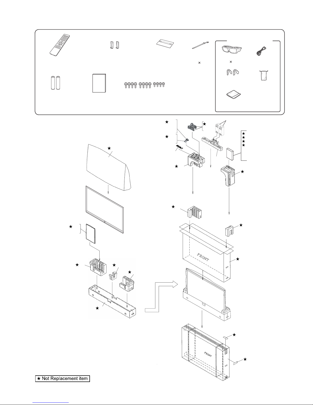
[7] SUPPLIED ACCESSORIES/PACKING PARTS (PRO-70X5FD)
PRO-60/70X5FD
X4
3D Glasses Accessories
X5
Remote control (x1)
X10
“AA” size battery (x2)
X1 X2 X6
Stand support Ass'y (x2) Stand Base Ass'y (x1)
X9
Operation manual (x1)
X3
Stand Screw Ass'y (x1)
S3
Cable tie
X7 Brochure (E)
X7 Brochure (F)
X8 Guarantee card
S12
X6
X10
S11
X3
X5
S4
3D Glasses
(
(
1)
2)
Nose pad *1
(small ×2, large ×2)
Cleaning cloth
(×2)
USB cable*2
(×2)
Glasses case
(×2)
X4
S9
X1
S6
S7
S8
S13
X7
X8
S4
X9
S4
S10
X2
S5
S5
S5
S1
S5
S5
S2
S14
S14
9
Page 86
PRO-60/70X5FD
NO. PARTS CODE
PRICE
RANK
NEW
MARK
PAR T
DELIVERY
DESCRIPTION
[7] SUPPLIED ACCESSORIES/PACKING PARTS (PRO-70X5FD)
X1 CANGKD276WJ01 X Stand Support Ass'y, x2
X2 CDAi-A778WJ32 N X Stand Base Ass'y
X3 CSAKKA011WJ01 X Stand Screw Ass'y
X4 AN-3DG20-EL N X 3D Glasses Accessories, x2
X5 RRMCGA937WJSA N X Remote Control
X6 LHLDWA303WJKA AE J Cable Clamp
X7 TCTLZA001WJZZ N X Brochure (E)
X7 TCTLZA002WJZZ N X Brochure (F)
X8 TGAN-B661WJZZ N X Guarantee Card
X9 TiNS-F205WJZZ N X Operation Manual
X10 Not available - - "AA" size battery, x2
S1 SPAKCG444WJZZ - N - Packing Case (NOT REPLACEMENT ITEM)
S2 SPAKCG445WJZZ - N - Packing Case (Bottom) (NOT REPLACEMENT ITEM)
S3 SPAKPB733WJZZ - - Wrapping Paper (NOT REPLACEMENT ITEM)
S4 SPAKXD447WJZZ - N - Packing Add. (Top) (NOT REPLACEMENT ITEM)
S5 SPAKXD448WJZZ - N - Packing Add. (Bottom) (NOT REPLACEMENT ITEM)
S6 SPAKFC160WJZZ - N - Outer Case (NOT REPLACEMENT ITEM)
S7 SPAKFC161WJZZ - N - Remocon Case (NOT REPLACEMENT ITEM)
S8 SPAKFC162WJZZ - N - Manual Cover (NOT REPLACEMENT ITEM)
S9 SPAKPB723WJZZ - N - Wrapping Paper (Support) (NOT REPLACEMENT ITEM)
S10 SPAKPB791WJZZ - N - Wrapping Paper (Stand) (NOT REPLACEMENT ITEM)
S11 SSAKKA011WJZZ - N - Polyethylene Bag (NOT REPLACEMENT ITEM)
S12 SSAKAA032WJZZ - - Polyethylene Bag (NOT REPLACEMENT ITEM)
S13 SSAKAA185WJZZ - N - Polyethylene Bag (NOT REPLACEMENT ITEM)
S14 TLABKA009WJZZ - - Case No. Label (NOT REPLACEMENT ITEM)
[8] SERVICE JIGS (USE FOR SERVICING)
N QCNW-C222WJQZ AW J Connecting Cord L=1000mm, 80pins, LCD Control Unit to LCD Panel Unit, x2
N QCNW-L214WJQZ AV J Connecting Cord L=1000mm, 64pins, LCD Control Unit to LCD Panel Unit, x2
N QCNW-F676WJQZ BH J Connecting Cord L=1000mm, 41pins, Main to LCD Control Unit (LW)
N QCNW-L795WJQZ BC J Connecting Cord L=1000mm, 24pins, Main to POWER Unit (PD)
N QCNW-G405WJQZ AP J Connecting Cord L=1000mm, 4pins, Power to LCD Control Unit (PL)
N QCNW-L519WJQZ N J Connecting Cord L=1000mm, 18pins, Power to LED Drive Unit (LA)
N QCNW-F139WJQZ N J Connecting Cord L=1000mm, 13pins, LCD Control Unit to LED Drive Unit (LB)
10
Page 87

PRO-60/70X5FD
Page 88

PRO-60/70X5FD
COPYRIGHT © 2011 BY SHARP CORPORATION
ALL RIGHTS RESERVED.
No Part of this publication may be reproduced,
stored in a retrieval system, or transmitted in
any from or by any means, electronic, mechanical,
photocopying, recording, or otherwise, without
prior written permission of the publisher.
Aug. 2011
SH. DS
SHARP CORPORATION
AV Systems Group
CS Promotion Center
Yaita,Tochigi 329-2193, Japan
 Loading...