

Page 1
SERVICE MANUAL
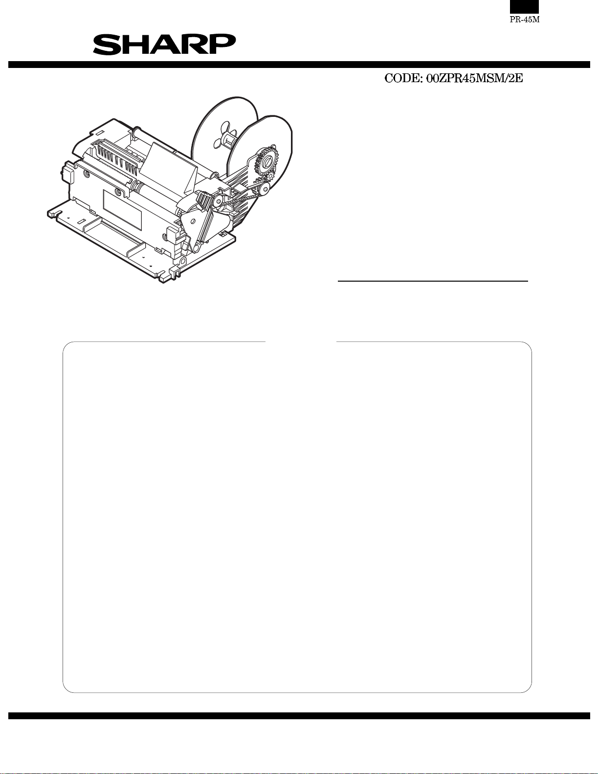
THERMAL PRINTER
MODEL PR-45M
PR-45M : MANUAL CUTTER
CONTENTS
CHAPTER 1. SPECIFICATIONS . . . . . . . . . . . . . . . . . . . . . . . . . . . . . . . . . . . . 1
CHAPTER 2. OUTLINE OF DRIVING CIRCUIT . . . . . . . . . . . . . . . . . . . . . . . . 3
CHAPTER 3. HANDLING THE PRINTER . . . . . . . . . . . . . . . . . . . . . . . . . . . . . 5
CHAPTER 4. MAINTENANCE. . . . . . . . . . . . . . . . . . . . . . . . . . . . . . . . . . . . . . 7
CHAPTER 5. TROUBLESHOOTING. . . . . . . . . . . . . . . . . . . . . . . . . . . . . . . . . 8
CHAPTER 6. DISASSEMBLY AND ASSEMBLY. . . . . . . . . . . . . . . . . . . . . . . 12
CHAPTER 7. PWB LAYOUT . . . . . . . . . . . . . . . . . . . . . . . . . . . . . . . . . . . . . . 21
PARTS GUIDE (Ki-OB2359BHZZ)
APPLICATION MODEL (As of Dec.)
ER-A455X Series, ER-A450/A450S ("V" Version), ER-A450T ("U" and "A" Version)
This document has been published to be used
SHARP CORPORATION
for after sales service only.
The contents are subject to change without notice.
Page 2
CHAPTER 1. SPECIFICATIONS
2. Specifications
1) Printer
Item Description
No. of station 2: Receipt and Journal
Validation No
Printing system Line thermal
No. of dot Receipt: 288 dots
Journal 288 dots
Dot pitch Horizontal: 0.125 mm
Vertical: 0.125 mm
Font 10 dots (W) × 24 dots (H)
Printing capacity Receipt: Max. 24 characters
Journal: Max. 24 characters
Character size 1.25 mm (W) × 3.0 mm (H): At 10 × 24 dots
Print pitch Column distance: 1.5 mm
Row distance: 3.75 mm
Paper feed speed Approximate 50 mm/s
Reliability Mechanism: MCBF 5 million lines
Thermal head: 5 million pulses
Paper end sensor Yes (Receipt and Journal)
Cutter Manual
Paper near end sensor No
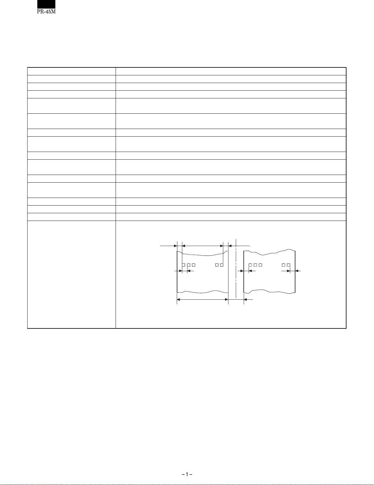
Printing area
(4.5) (4)
0.125
288dots
(36)
44.5 ±0.5
3.0
(4)
(4.5)
UNIT: mm
Page 3
Item Description
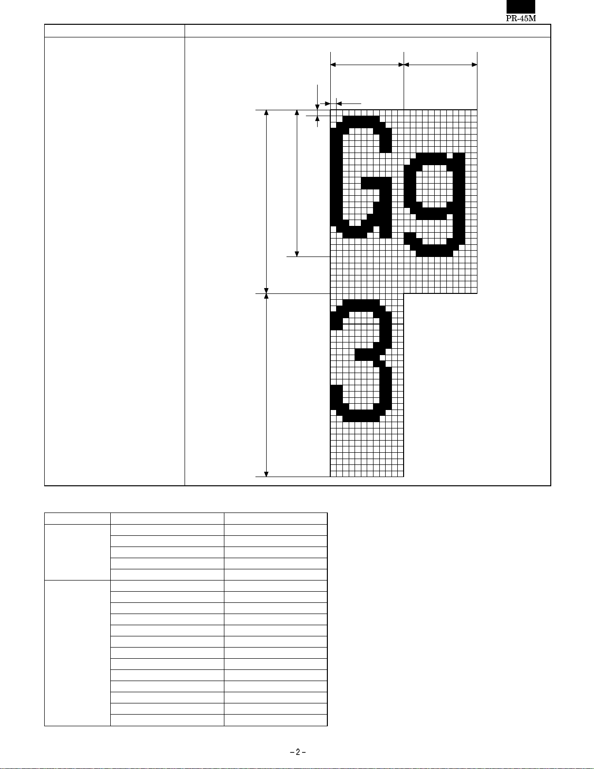
Printing format 12 × 24 font
1.5 (12dots) 1.5 (12dots)
0.125
0.125
3.0 (24dots)
3.75 (30dots)
2) Tools required for maintenance and repair
For NAME Remarks
Mainrenance Cleaning brush
Cotton swab
Clean cloth
Alcoholic solvent Ethanol, Methanol, IPA
Cleaning brush
Repair (+) Screwdriver
(-) Screwdriver
Tweezers
Pliers
Nippers
Soldering iron
ET holder
Grease : G-36 00BB703600001
Cleaning brush
Cotton swab
Clean cloth
Alcoholic solvent Ethanol, Methanol, IPA
Cleaning brush
3.75 (30dots)
UNIT: mm
Page 4
CHAPTER 2. OUTLINE OF DRIVING
CIRCUIT
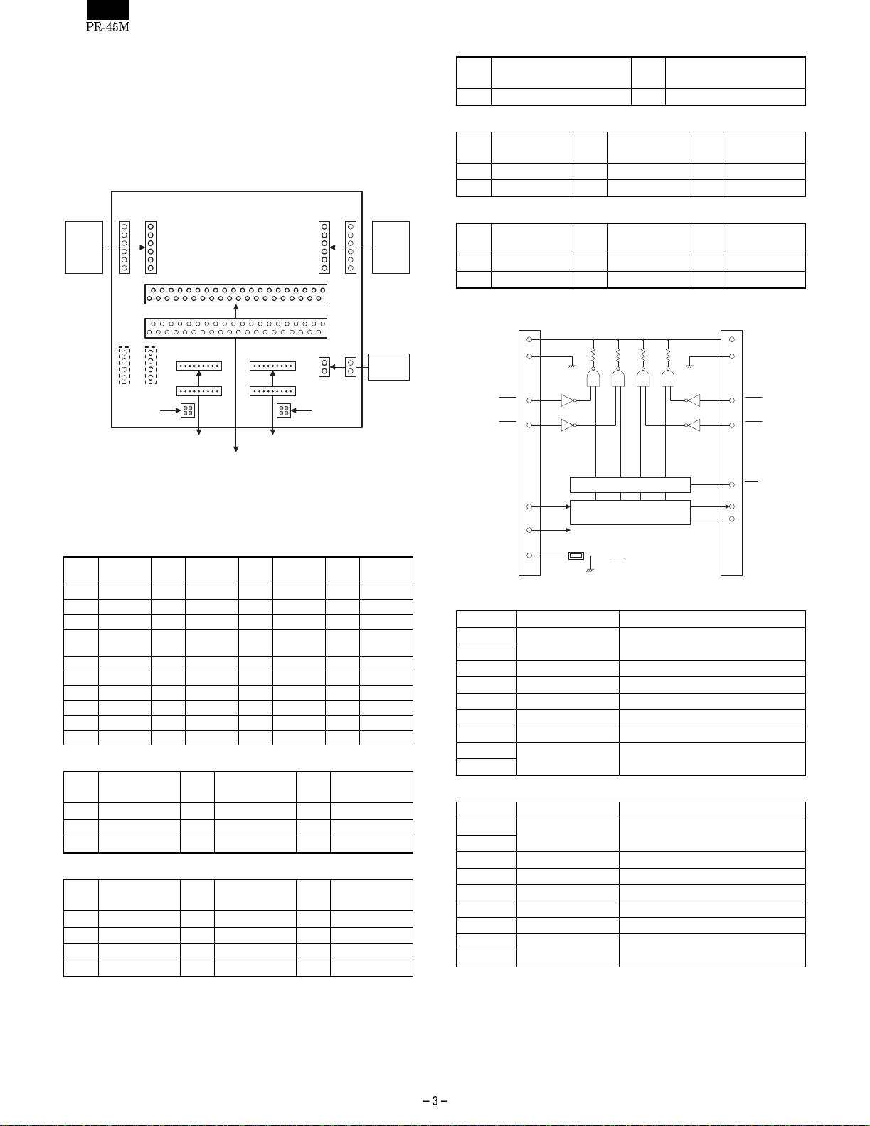
1. Block diagram & Connection diagram
1) Block diagram
CON2(9P)
FOR ECR PWB
Signal
GND
Pin
No.
2
5
8
Pin
No.
PWB UNIT
CON1(40P)
Pin
No.
15
Signal
VH
/LAT
GND
Signal
CON3(9P)
TM
Signal
CON7(6P)
CON5(2P)
Non-paper
detection
sensor(R)
Pin
No.
3
6
9
Pin
No.
Pin
No.
16
Dout
/STB3
GND
6
HEAD UP
SENSOR
Signal
VDD
(+5V)
Signal
Signal
MOTOR
CON6(6P)
J
6
MOTOR
CON4(4P)
Non-paper
detection
sensor(J)
FOR THERMAL HEAD FOR THERMAL HEAD
2) Connector table
Connect to the ECR PWB
CON1: <For ECR PWB>
PinNo. Signal
1VHIN 2NC 3NC 4NC
5 VJCOM 6 VJPFD 7 /JPFA 8 /JPFB
9 /JPFC 10 /JPFD 11 /JPES 12 GND
GND
13
17 /STB4 18 /STB3 19 Din 20 VH
21 VH 22 VH 23 VH 24 Dout
25 CLK 26 /LAT 27 /STB2 28 /STB1
29 GND 30 GND 31 GND 32 /RPES
33 VRCOM 34 VRCOM 35 /RPFA 36 /RPFB
37 /RPFC 38 /RPFD 39 PHUPS 40 VHOUT
CON2: <For Thermal head connector A>
Pin
No.
1VH
4 CLK
7 /STB1
CON3: <For Thermal head connector B>
Pin
No.
1GND 2GND 3NC
4 TM 5 VDD (+5V) 6 /STB4
7/STB3 8Din 9VH
10 VH
CON4: Not used
Pin
No.
14
Signal
Signal
CON5: <For Head up detector>
Pin
No.
Signal
Pin
No.
Signal
1 PHUPS 2 GND-L
CON6: <For Journal paper feed motor>
Pin
No.
Signal
Pin
No.
Signal
Pin
No.
Signal
1VJCOM 2VJCOM 3/JPFA
4/JPFB 5/JPFC 6/JPFD
CON7: <For Receipt paper feed motor>
R
Pin
No.
Signal
Pin
No.
Signal
Pin
No.
Signal
1 VRCOM 2 VRCOM 3 /RPFA
4/RPFB 5/RPFC 6/RPFD
3) Thermal head block diagram
DOT #864
8, 9
VH
DI
TM
Connector B
1, 2
5
6
7
4
3
4 3
THERMISTOR
LATCH REGISTER
SHIFT REGISTER
The STB terminal is pulled
in the IC.
GND
STB4
STB3
VDD
Thermal head connector A
Pin No. Signal Description
1
VH Head application voltage
2
3 D out Data output signal
4 CLK Clock signal
5 /LAT Latch Signal
6 /STB2 Strobe Signal 2
7 /STB1 Strobe Signal 1
8
GND GND
9
Thermal head connector B
Pin No. Signal Description
1
GND GND
2
3 TM Thermistor detecting signal
4VDD +5V
5 /STB4 Strobe Signal 4
6 /STB3 Strobe Signal 3
7 D in Data input signal
8
VH Head application voltage
9
Print data which has been entered through Din signal synchronization
with the CLOCK signal is stored in /LAT according to the timing (864
dots) of the /LATCH signal. Stored print data is output by the
/STROBE1, /STROBE2, /STROBE3, and /STROBE4 signals to energize the heating element. The print data (864 dots) is divided by four
STROBE signals into the following four parts before being output.
DOT #1
12
1, 2
8, 9
7
6
5
3
4
Connector A
VH
GND
STB1
STB2
LAT
DO
CLK
Page 5
STROBE No. DOT No. Dots/ Strobe Note
/STROBE4 577 ∼ 864 288 Excluding dots No.1 ∼ 88,
/STROBE3 433 ∼ 576 144
/STROBE2 289 ∼ 432 144
/STROBE1 1 ∼ 288 288
377 ∼ 488 and 777 ∼ 864
4) Motor block diagram
stepping motor
/RPFA, /JPFA
/RPFB, /JPFB
/RPFC, /JPFC
/RPFD, /JPFD
VRCOM, VJCOM
VRCOM, VJCOM
<JOURNAL MOTOR>
PIN
SIGNAL
No.
<RECEIPT MOTOR>
PIN
No.
The paper feed motors are stepping motors with 4-phase driving
coils. The motors are driven by switching over the driving coils.
<MOTOR DRIVE SEQUENCE> ON: Energized/OFF: Not energized
JOURNAL MOTOR
STEP No. PHASE A PHASE B PHASE C PHASE D
NAME
1
VJCOM COMMON voltage
2
3/JPFA
4/JPFB
5/JPFC
6/JPFD
SIGNAL
NAME
1
VRCOM COMMON voltage
2
3/RPFA
4/RPFB
5/RPFC
6/RPFD
1ONOFFOFFON
2ONOFFONOFF
3 OFF ON ON OFF
4OFFONOFFON
JOURNAL-side paper feed motor phase A
driving signal
JOURNAL-side paper feed motor phase B
driving signal
JOURNAL-side paper feed motor phase C
driving signal
JOURNAL-side paper feed motor phase D
driving signal
RECEIPT-side paper feed motor phase A
driving signal
RECEIPT-side paper feed motor phase B
driving signal
RECEIPT-side paper feed motor phase C
driving signal
RECEIPT-side paper feed motor phase D
driving signal
DESCRIPTION
DESCRIPTION
C
D
AB
M
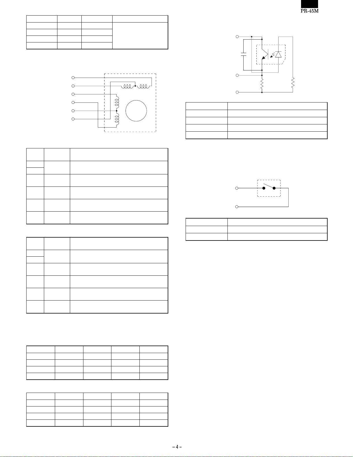
5) End sensor block diagram
reflex photo sensor
+5V
0.1µF
/RPES, /JPES
GND-L
SIGNAL NAME DESCRIPTION
+5V +5V
/RPES Receipt paper end sensor detecting signal
/JPES Journal paper end sensor detecting signal
GNDL GND
The photo diode on the PWB detects the presence/absence of the
paper passing under the journal and receipt platens.
3
2
4
1
39KΩ 220Ω
6) Head up sensor
micro switch
PHUPS
GND-L
SIGNAL NAME DESCRIPTION
PHUPS Head-up detecting signal
GNDL GND
The micro switch at the left side of the printer detects the head-up
state.
ON: Head-down
OFF: Head-up
RECEIPT MOTOR
STEP No. PHASE A PHASE B PHASE C PHASE D
1ONOFFONOFF
2ONOFFOFFON
3OFFONOFFON
4 OFF ON ON OFF
Page 6
CHAPTER 3. HANDLING THE
PRINTER
1 Special Handling Considerations
(1) When transporting the printer
•
When transporting the printer, the head up le ver should be raised
in the
B: Head up position so that the head does not contact the
platen rollers.
Failure to do so will may result in pear the printer performance.
• When the printer is carried, it should not be held at the connectors,
the lead wires, paper take-up frame, etc.
• When carrying the printer, never allow large impacts to occur, such
as by dropping, collision, etc.
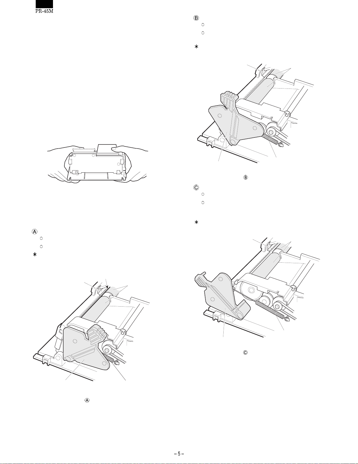
• When carrying the printer, hold the frame with both hands, as
shown in the figure below.
:Head-up position
The head is not in contact with the platen roller.
When the printer is out of service for a long time or when it
is to be transported.
The illustration shows the state when the PT-cover is removed
for explanation purposes only.
Head
Platen roller
Fig. Carrying the printer unit
• When transporting the printer, pack it using anti-static packaging.
Do not touch the thermal head and the surface of the PWB. When
handling the printer, properly ground yourself.
Head up lever position
: Close position
The head is in contact with the platen roller
The printer operates and feeds the paper.
The illustration shows the state when the PT-cover is removed
for explanation purposes only.
(In contact)
Head
Platen roller
Head Up Lever
Head-up position
Fig.
H-Spring
: Cleaning position
When the head and platen roller are to be cleaned.
Do not leave the head-up lever in this position; Failure to do
so might result in a deformed H-spring, thus leading to poor
print or paper feed quality.
The illustration shows the state when the PT-cover is removed
for explanation purposes only.
Head
Platen roller
Head Up Lever
Fig.
Close position
H-Spring
Head Up Lever
Fig.
H-Spring
Cleaning position
Page 7
(2) When storing the printer
Printer
• When stori ng the printer, make sure to raise the head up lever
in the
position or
: Head up position. Never store it with the : Close
: Cleaning position.
• Avoid st oring the printer in areas with a lot of dust, direct sun-
light, or high humidity.
• I f the printer is stored for an extended period, put it in a anti-
static bag and store it in a dry place.
• The t hermal paper should not be left for an extended period
(more than two weeks at normal temperature) held between
the platen roller and the head (
: Close position).
• Do not leave the printer in the : Checking position for more
than 2 days.
Paper (thermal paper)
• Since t hermal paper gradually darkens from about 70°C, pay
attention to heat, humidity, sun light, etc., regardless whether or
not the paper has been printed on.
• Avoid high temperature and high humidity areas.
• Avoid direct sun light.
(When thermal paper is left near the window in direct sun
light, the base color may change and discoloring may take
place.)
(3) When using the printer
Printer
• Since t he printer contains a thermal head, permanent magnets
(motor) and micro switches, avoid using it in areas with a lot of
iron powder, dust, etc.
• Never operate with no paper loaded.
• Never pul l out the paper (forward or backward) with the head
head against the platen rollers.
• Do not touch the head heating elements and driver Ics, espe-
cially with hard or metal objects.
• Duri ng printing and just after printing completes (for about 15
minutes), the area around the head and the motor surface are
very hot. Never directly touch them with your hand.
• Operate the head up lever only when required.
Never touch the surface of the head heating elements.
(Dirt may stick to the heating elements and affect the printing.)
• Never leave the printer with the platen rollers and the head
directly touching (
Do not leave the head-up lever in the
more than 2 days.
(When the printer is left for a while, make sure to raise the head
up lever in the ➡
: Close position).
: Cleaning position for
: direction in Fig. Loading paper.)
• Since el ectronic parts are used in the print head, never touch
the thermal head with your bare hand.
Before handling the printer, execute proper body grounding
procedures to avoid static electricity.
Paper (thermal paper)
• Use only the specified thermal paper.
(Thermal paper with a rough surface may result in poor printer
quality and shorten the print head life.)
(4) When mounting the printer
•
Make sure the power is turned OFF before installing the printer to
an ECR.
• When att aching the printer to your product, avoid areas with a lot
of iron powder, dust, etc.
2. Loading the Paper (insertion and
removal)
Use only the paper specified in the specification sheet issued by our
company.
(1) Loading paper
Load paper following the procedure below.
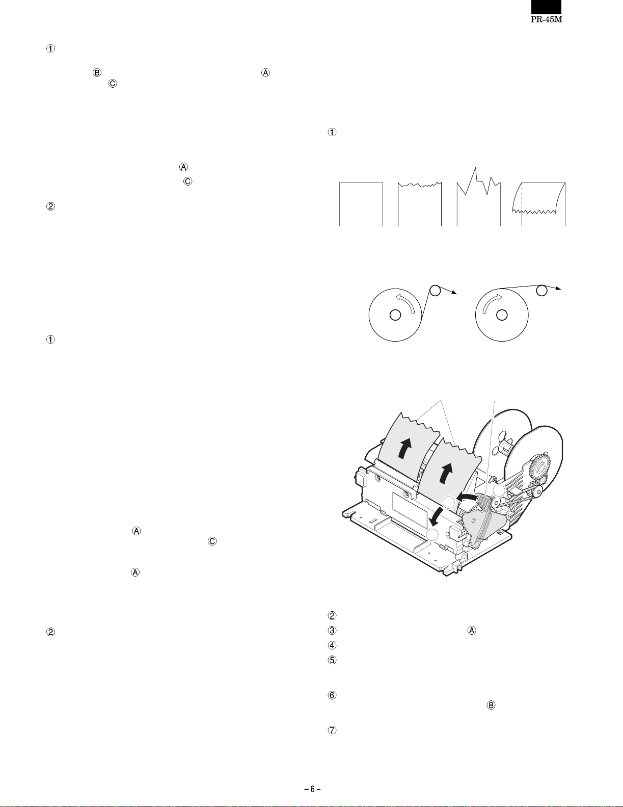
Cut the edge of the paper as shown in the figure below.
Good WrongGood Wrong
Fig. Shape of the cut paper edge
Good Bad
Fig. Paper setting state
Recording paper
B
C
Fig. Loading paper
Turn the ECR ON.
Make sure the head-up lever in the (Close) position.
Insert the paper through the paper inlet.
The paper is automatically loaded into the printer by the auto
loading mechanism and the leading edge of the paper roll is delivered a little from the paper outlet.
If there is slackness in the paper or paper is loaded slantly, set the
head up lever in the head up position
position.
If the length of the paper delivered from the outlet is insufficient,
feed the paper properly with the key board of the ECR.
(Notes) If paper is fed without following the above procedure, it
could cause improper paper feeding and jamming.
Head up lever
A
and adjust the paper
Page 8
(2) Unloading the paper
The paper can be unloaded in two ways.
Move the head up lever toward : Head up position and then pull
the paper out by hand in the forward direction (feeding direction)
or in the reverse direction.
Operate the paper feed mechanism to discharge the paper from
the printer. Move the head up lever to the head up position
remove the paper toward the front.
• Operations other than those listed above could cause im-
(Notes)
proper paper feeding and jamming, and could cause
breaking of the head heating elements.
and
• Never pull the paper out without using the head up lever,
regardless of the direction, forward or reverse.
(3) Removing paper after a paper jam
If a paper jam occurs, follow the procedure below.
Put the head-up lever in the Cleaning position to widen the
spacing between the head and platen rollers so that you can
easily check for a paper jam.
Remove a jammed paper by hand.
Return the head-up lever in the Close position.
When a tool such as tweezers, is used to remove paper chips, take
care not to touch the heating elements of the head with the tool.
Since the head is still hot just after the operation printing is stopped,
wait a while for the head to cool down.
CHAPTER 4. MAINTENANCE
2. Inspection
The maintenance and inspection items for the printer are dividend
into 2 types. One is "Daily checks" for the person who uses the
printer, and the other is "Periodic checks" for someone with more
technical knowledge. Maintenance and inspections should be carried
out by properly qualified personnel.
(1) Daily checks
Check that the printer is used properly and kept in the good repair.
Daily check items
The specified paper is being used.
The paper has not become discolored.
Check print quality and if significant deterioration is found, clean
the head heating elements.
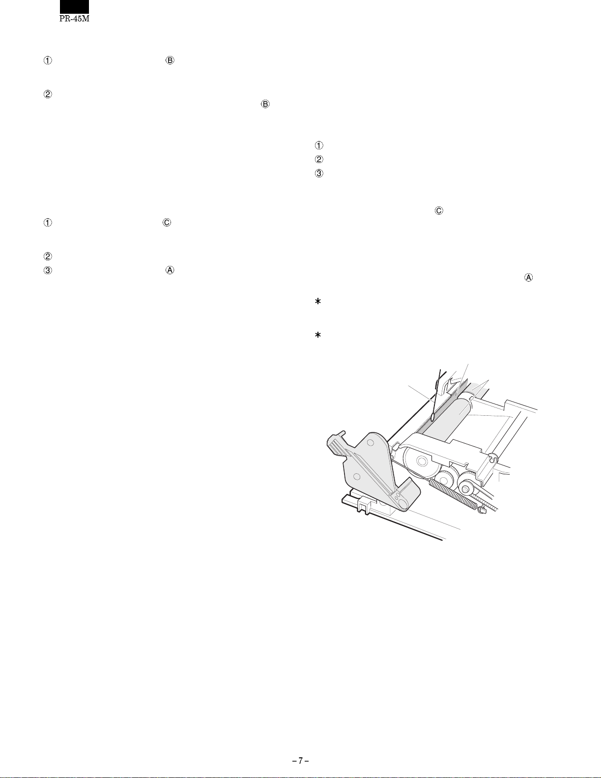
<Head cleaning method>
1) Place the head-up lever in the
is securely lock ed .
2) Wipe the heating element of the head and platen rollers clean with
a soft cloth or cotton pledget moistened with alcoholic solvent
(ethanol, methanol or IPA: isopropyl alcohol).
3) After making sure the alcoholic solvent has thoroughly evaporated, undo the head-up lever and platen rollers in t he
position.
If paper dust is attached to the platen roller surface, the paper
feeding power is reduced. Be sure to clean the platen roller surface when cleaning the head.
The illustration shows the state when the PT-cover is removed for
explanation purposes only.
: Cleaning position. Make sure it
Close
Thermal head unit
To maintain proper performance of the printer for a long period of
time and to prevent trouble, carry out the maintenance and management procedures as follows.
1. Cleaning
• Removing stains
Wipe dirt off the head and platen rollers with a clean cloth saturated with an alcoholic solvent (ethanol, met hanol, IPA: Isopropyl
alcohol).
For cleaning the head part, refer to daily checks.
(Notes) Never use thinner, benzine, trichlene or ketone group sol-
vents, since they may damage or deteriorate rubber and
plastic parts.
• Removing dust and fuzz
Cleaning by suction (with a vacuum cleaner) is desirable.
Suck up all the dust and fuzz.
(Notes) Check lubrication at various points after cleaning, and lubri-
cate with oil at the specified locations.
Cotton swab
Fig. Head and Platen roller cleaning
Platen roller
Page 9

(2) Periodic checks
Check the items listed in the table below every 6 months, and correct
any problems.
Table of periodic checks
No. Check items Standard Procedure
1 Dust, fuzz and dirt
sticking to various
parts.
2 Lubrication • See "Chapter 6". • Refer to "Chapter 6" For lubrication.
3 Operational check • Printing is operated without abnormality. • See "Chapter 5".
• The mechanism should not have a lot of dirt, fuzz or dust on its
surface. Foreign substances should not be allowed to collect.
• The paper guide should not be clogged with paper chips, etc. • Remove paper chips with a tweezers.
• Feeding operated without abnormality.
• Observe respective functions. Abnormal operation caused by parts
wear, deformation, bending, etc., do not exist.
• Clean the unit with a vacuum cleaner.
• See "Chapter 5" and "Chapter 6".
CHAPTER 5. TROUBLESHOOTING
Troubleshooting and repair of the printer is classified into two levels
(A and B), depending on the difficulty of the repair.
Persons undertaking a repair should consider their level of technical
skill and the level of the repair before attempting to ensure that the
trouble is handled correctly.
1. Repair Levels
Level A: This requires general knowledge about the operating princi-
ples and structure of the printer, along wi th technical skill
and minimum experience.
Level B: This requires full knowledge of the operating principles and
structure of the printer, adequate technical skill, and repair
experience.
3. Repair Guidelines
2. Repair Procedures
If trouble occurs, observe the symptoms, determine the cause by
referring to Section 3 "Repair Guidelines," and repair it. The "Repair
Guidelines" are divided into the following five columns so that any
trouble can be analyzed and a solution found.
• Problem
Check for symptoms.
• Condition
Compare the problem with the examples given i n this column and
determine if they match.
• Cause
Causes that can be assumed for the problem are listed.
Determine the cause. Also, refer to the repair level indicated for
each cause.
• Checkpoints and Checking Method
How to check for the cause of a problem is listed. Check the
defective part as instructed in this column.
• Repair Method
Repair the defective part as instructed in this column. If the same
problem occurs after the repair, check the other causes in the
"Cause" column again, and repair accordingly.
Phenomenon Condition Cause Level
1. Printing is
not executed.
Nothing is
printed.
(1) The Head cable is
disconnected.
(2) The common or signal line of
the Head cable is broken.
(3) The printhead does not
contact the platens.
(4) The input pulse is defective B • Verify with the oscilloscope
Checkpoints and
Checking Method
A • Verify that the Head cable
is properly connected.
B • Check the common and
signal lines of the Head
cable for continuity.
A • Verify that the head up
lever is set to the proper
position.
that the input pulse is
within the specified range.
Repair Method
• If the FFC-head is not
properly connected,
connect it firmly.
• If continuity cannot be
confirmed, replace the
Head cable.
• Set the head up lever to
the printing position.
• If the input pulse is not
generated or is not within
the specified range, adjust
the drive control circuit.
Page 10

Phenomenon Condition Cause Level
2. Dots are
missing
continuously.
A specific dot is
not printed.
(1) A foreign substance is
attached to the heating
elements of the printhead.
(2) The heating elements of the
printhead are damaged.
(3) The signal line of the Head
cable is broken.
(4) The input pulse is defective. A • See Cause (4) of Phenomenon 1.
3. Dots are
missing
occasionally.
Dots are
missing
occasionally or
the color of
some dots
becomes light.
(1) A foreign substance is
attached to the surface of
each platen roller.
(2) The surface of each platen
roller is deformed.
(3) A foreign substance is
attached to the heating
elements of the printhead.
(4) The heating elements of the
printhead are damaged.
4. The printing
color is light.
The overall
printing color is
(1) The head up lever position is
not correct.
light.
(2) Displaced or deformed
H-springs.
(3) The H/C frame is warped. B • Verify that the H/C frame is
(4) The surface of the platen is
deformed.
(5) The heating elements of the
printhead have deteriorated.
(6) The input pulse is defective. A • See Cause (4) of Phenomenon 1.
(7) The roll paper is of poor
quality.
5. Paper
cannot be
loaded.
The end of the
roll paper
cannot be
(1) The leading edge of paper roll
is improperly cut .
inserted into the
paper guide
section.
(2) A piece of paper is blocking
the paper guide path.
Checkpoints and
Checking Method
A • Verify that nothing is
• Clean the heating elements
attached to the heating
elements of the printhead.
B • Verify that the heating
• If the heating elements are
elements of the printhead
are not damaged.
B • See Cause (2) of Phenomemon 1.
A • Verify that nothing is
• Clean the surface of each
attached to the surface of
each platen roller.
A • Verify that the surface of
• If deformation is found,
each platen roller is not
deformed.
A • See Cause (1) of Phenomenon 2.
B • See Cause (2) of Phenomenon 2.
A • Verify that the head up
• Set the head up lever to
lever is set to the correct
position.
A • Make sure the H-springs
• If they are not correctly
are correctly installed and
not deformed.
• If the H/C frame is warped,
not warped.
A • See Cause (2) of Phenomenon 3.
B • Verify that the heating
• If any deterioration is
elements of the printhead
have not deteriorated.
A • Verify that the specified-roll
• Use the specified quality
paper is being used.
• Check the paper for proper
color development and
excessive dust.
A • Check that the leading
• If the leading edge of the
edge of the paper roll is
properly cut and is not
folded.
A • Verify that no piece of
• Remove the paper.
paper is blocking the paper
path.
Repair Method
of the printhead.
damaged, replace the
thermal head.
platen roller.
replace the corresponding
platen roller ass’y.
the printing position.
installed, reinstall properly.
Replace any deformed
H-spring with a new one.
replace the head mounting
deck ass’y.
found, replace the thermal
head.
paper.
paper roll is improperly cut,
cut it properly and insert
into the printer again.
Note:
When removing the piece
of paper be sure not to
damage the printhead and
platen roller with any tools.
Page 11

Phenomenon Condition Cause Level
6. Paper is not
fed.
Roll paper is not
fed, and printing
(1) Roll paper feeding is
defective.
is repeated on
the same line.
(2) A foreign substance is
attached to part of the power
transmission mechanism unit,
or any of the gears in the unit
are damaged.
(3) The paper feed motor is
damaged.
(4) The paper feed motor drive
signal is defective.
7. The paper
feed pitch is
The line spacing
is not uniform.
(1) Roll paper is not being fed
correctly.
not uniform.
(2) The feeding load of a paper
roll exceeds the specification.
(3) Paper is jammed in the paper
guide.
(4) The paper feed motor drive
signal is defective.
(5) The head up lever position is
not correct.
8. Paper end
detection is
not corrected.
Although paper
exists in the
paper guide
(1) The paper end detector is
defective.
path, the out-ofpaper state
continues.
When paper is
removed from
the paper guide
path, the printer
does not enter
the out-of-paper
(1) A piece of paper or foreign
substance is blocking the
paper path.
(2) The paper end detector is
defective.
state.
Checkpoints and
Checking Method
A • Verify that the specified roll
• Use the specified roll paper.
paper (width, thickness,
and diameter) is being
used.
• Verify that the roll paper is
• Load the roll paper
loaded properly in the
paper supplying device.
B • Verify that no foreign
• Tension: ≤50g-cm
• If any foreign matter is
matter attached to any part
of the power transmission
mechanism unit and that
• If any of the gears are
no gears are damaged.
B • Check the resistance at
• If any abnormality is found,
each coil of the
corresponding paper feed
motor
Resistance: Approx.
Resistance:90Ω±10%
B • Verify that the
• If the drive signal is not
corresponding paper feed
motor drive signal is
normal.
A • See Cause (1) of
Phenomenon 6.
• Check the platen roller for
• If deformed, replace the
deformation.
A • See Cause (2) of
Phenomenon 6.
• The paper roll isn’t set
• Reset the paper roll properly.
properly.
• The paper roll doesn’t meet
• Use a paper roll which
the specification in size.
B • Paper is jammed in the
• Remove paper. At this
paper guide.
B • See Cause (4) of Phenomenon 6.
A • See Cause (1) of Phenomenon 4.
B • Check the signal level on
• If the signal level is
the paper end detection
circuit board.
B • Verify that nothing is
• If anything is blocking the
blocking the paper path.
B • See Cause (1) of Phenomenon 8.
Repair Method
correctly.
attached, remove it.
damaged, replace them.
replace the paper feed
motor.
output or is not within the
specified range, adjust the
drive circuit.
platen roller with a new one.
meets the specification in
size.
time, use caution to
prevent damage to the
platen roller.
abnormal, replace the
paper guide ass’y.
paper path, remove it.
Page 12

Phenomenon Condition Cause Level
9. Roll paper is
not taken up.
Roll paper is fed
but not taken up.
(1) The paper take up shaft is
worn or damaged.
(2) SP gear, C-spring or pulley is
worn or doesn’t rotate
smoothly.
(3) Some of the gear teeth are
worn or damaged.
(4) The paper take up belt is worn
or stretched.
10. Paper
cannot be
taken up
properly.
Because the
tension to take
up the roll paper
is weak, the
diameter of the
paper taken up
becomes larger.
(1) The paper take up shaft is
worn or damaged.
(2) SP gear, C-spring or pulley is
worn or doesn’t rotate
smoothly.
(3) Paper roll swerves. B • Verify that the paper take
(4) Some of the gear teeth are
worn or damaged.
(5) The paper take up belt is worn
or stretched.
Checkpoints and
Checking Method
B • Verify that the paper take
up shaft is not worn or
damaged.
B • Check paper winding parts
for wear and damage.
Repair Method
• If any wear or damage is
found, replace the paper
take up shaft.
• If wear or damage is found,
replace the part with a new
one.
B • Verify that no teeth are
worn or damaged.
• If any of the gear teeth are
worn or damaged, replace
the gear.
B • Verify that the paper take
up belt is not worn or
stretched.
• If the paper take up belt is
worn or stretched, replace
it.
B • See Cause (1) of Phenomenon 9.
B • Replace SP gear, C-spring or pulley with new one.
• If any deformation or warp
up frame sub ass’y is not
deformed or warped.
is found, replace the paper
take up frame sub ass’y.
B • See Cause (3) of Phenomenon 9.
B • See Cause (4) of Phenomenon 9.
Page 13

CHAPTER 6 DISASSEMBLY AND ASSEMBLY
• This chapter mainly outlines the procedure for disassembling the
printer. It is advisable to reinstall the printer in the reverse order
from disassembly, referring to "Cautions t o be taken when installing."
• Some easy steps have been omitted.
• Only part names are described without indicating their part codes.
For the part codes, refer to the Parts Guide.
[Cautions to be taken when working on the printer]
1) The parts which need to be greased are indicated in "Cautions to
be taken when reinstalling." Whenever such a part is replaced
with a new one, grease it before installing.
1 REMOVE THE CUTTER45 and
H-COVER45
1
Lubrication interval (rough guide)
• Every 6 months
• Every 2 years or 2,000,000 lines of printing
• Part s code of lubricant
Lubricant type PARTS CODE PRICE RANK
G36 00BB703600001 AU
2) Use caution not to have the gear chipped or deformed when
removing or reinstalling.
3) Do not touch directly the printing head.
4) Be sure to wear an earth band to ground your body.
[PARTS LIST]
No. PARTS NAME Q’ty
CUTTER45
H-COVER45
SCREW (M2×8)
CAUTION LABEL
1
1
3
1
3
4
2
Fig. 1
[DISASSEMBLY METHOD]
1) Remove the CUTTER45 and H-COVER45 :
Using a Phillips screwdriver, remove the three SCREWs
Remove the CUTTER45
The H-COVER45
and H-COVER45 .
carries the "CAUTION" label .
.
Page 14

2 REMOVE THE MANUAL CUTTER
3
2
[DISASSEMBLY METHOD]
1) Remove the G-COVER45
Using a screwdriver, raise the two tabs of the G-COVER45
and remove the G-COVER45 from the PRINTER FRAME45
.
1
Fig. 2
4
[PARTS LIST]
No. PARTS NAME Q’ty
PRINTER FRAME45
G-COVER45
SCREW (M2 × 8)
PT-COVER
2) Remove the SCREWs
Insert a flat-bladed screwdriver into the slit shown in the fig-
ure below.
Apply force into the direction indicated by the arrow, to raise
the tang and pull out the PT-COVER upward.
. Remove the PT-COVER .
1
1
3
1
Along the right side in the slit,
(A)
2
Fig. 3
1
Insert a screwdriver (-) here.
PT-COVER
Fig. 4
Page 15

3 REMOVE THE HEAD UNIT
1
E
5
4
6
4
A
1
E
A
2
[PARTS LIST]
No. PARTS NAME Q’ty
H-SPRING
HEAD UP LEVER
E-RING
SCREW (M3 × 6)
THERMAL HEAD
H/C FRAME
Use caution not to touch the heating element of the HEAD
and PWB.
2
1
1
2
1
1
3
Fig. 5
[DISASSEMBLY METHOD]
1) Remove the H-SPRINGs on the right and left sides of the
printer frame.
<Note> Pinch the H-SPRING at point E with long-nose pliers
2) Remove the HEAD UP LEVER
3) Remove the E-RING
4) Remove the H/C FRAME UNIT (Part of the assembly of the
THERMAL HEAD
<Note> Use caution not to damage or deform the H/C FRAME
5) Remove the two SCREWs
and remove it taking care not to deform the rib of the
HOUSING A.
H-spring
Pinch here with long-nose pliers.
Fig. 6
.
.
and H/C FRAME ).
UNIT by inadvertently hitting them with the ROLLERs
and gears.
and remove the THERMAL HEAD
from the H/C FRAME .
[GREASING]
Apply grease on the two mounting areas A of the H/C FRAME .
Page 16

[Cautions to be taken when reinstalling]
1. Adju sti ng the HEAD position
Whenever the THERMAL HEAD
adjust its position for the H/C FRAME
is replaced with a new one,
.
• Procedure:
1) The screw hole for fixing the HEAD
is made a slot as shown in the figure below. First, align
the screw hole in the HEAD
slot and temporarily secure it with the SCREW
2) Install the H/C FRAME UNIT
3) Adjust the HEAD position and make sure that heating
element of the HEAD
performing a printing test. Do not adjust the Head position
during printing; otherwise the HEAD might break down
due to friction.
<Procedure for adjusting HEAD position>
(1) Insert a flat-bladed screwdriver into the adjustment
hole C in the H/C FRAME
ward little by little with the screwdriver until it reaches
the desired position, and secure it with the SCREW
(tightening torque: 6.5 kgf-cm).
2. Direction of H-SPRING
Install the H-SPRINGs so that the hooks point outward.
1
is most properly positioned, by
in the H/C FRAME
with the bottom area of the
on the HOUSING .
. Adjust the HEAD up-
3. HEAD cable
Install the 9-pin connector to the right end of the THERMAL
HEAD
Use caution to make a good connection or a deformed connector when connecting the THERMAL HEAD
bles.
.
4. Installing HEAD UP LEVER and H-SPRING ("J" side)
and the 10-pin connector to the left end.
4
6
The number of pins on the
PWB unit:10P
The number of pins on the
PWB unit:9P
Fig. 8
1)
and HEAD ca-
5
4
H/C frame unit
H-SPRING ("J" side)
2
1
1
Fig. 7
2)
2
3
1
3)
Fig. 9
Page 17

4 REMOVE THE PLATEN ROLLER
5
6
1
2
3
Fig. 10
4
3
2
1
[DISASSEMBLY METHOD]
1) Remove the E-RING and the PF-GEAR .
2) Remove the E-RINGs (for bushing)
.
3) Remove the PLATEN ROLLER "J"
and the PT-HOLDER .
. Remove the BUSHINGs
, PLATEN ROLLER "R"
[Cautions to be taken when reinstalling]
1. How t o tell PLATEN ROLLER "J" fr om PLATEN ROLLER "R"
As shown in the figure below, the PLATEN ROLLER "J" has
a black line on it.
The two PLATEN ROLLERs have different polishing directions
of the rubber roller. Pay attention to the direction when installing
them.
( PLATEN ROLLER "J" )( PLATEN ROLLER "R" )
[PARTS LIST]
No. PARTS NAME Q’ty
E-RING
PF-GEAR
BUSHING
PLATEN ROLLER "J"
PLATEN ROLLER "R"
PT-HOLDER
E-RINGs (for bushing)
2. LUBRICATIONS
Apply grease on the PLATEN ROLLER "J"
ROLLER "R"
below.
( PLATEN ROLLER "R" )
( PLATEN ROLLER "J" )
, and PT-HOLDER in the points indicated
( PT-HOLDER )
4
4
Apply grease (G36)
on the
PLATEN HOLDER
shaft, 4 mm in width.
2
2
2
1
1
1
2
, PLATEN
Apply grease (G36)
inside the bushing.
without black line with black line
Fig. 11
Fig. 12
Page 18

5 REMOVE THE GEARS
5
Fig. 13
[PARTS LIST]
11
10
9
8
4
3
1
2
No. PARTS NAME Q’ty
IDLE GEAR-L
SCREW (M3 × 5)
WASHER
TIMING BELT
PULLEY GEAR
SPOOL UNIT
SCREW (M2×6)
PULLY
C-SPRING
SP-GEAR
IDLE GEAR-S
2
4
1
1
1
1
1
1
1
1
1
[DISASSEMBLY METHOD]
<RIGHT SIDE>
1) Remove the IDLE GEAR-L
2) Remove the SCREW
3) Remove the TIMING BELT
4) Remove the PULLEY GEAR
5) Remove the SCREW
<LEFT SIDE>
1) Remove the IDLE GEAR-L
<SPOOL UNIT>
1) Remove the E-RING
2) Remove the PULLEY
IDLE GEAR-S
and WASHER .
.
.
, C-SPRING , SP-GEAR and
.
[Cautions to be taken when reinstalling]
1. Please note the posi tion of the WASHER when securing the
.
.
.
.
WASHER
PULLEY
GEAR
The PRINTER
FRAME 45's shaft
2. LUBRICATIONS
Apply grease (G-36) on the IDLE GEAR-L
, SP-GEAR , and PRINTER FRAME (45) in the areas
indicated below.
( IDLE GEAR-L )
Apply grease on the gear teeth
contact and inside the shaft hole.
to with the SCREW .
SCREW
WASHER
Fig. 14
SCREW
WASHER
, PULLEY GEAR
( PULLY GEAR )
Apply grease inside the
gear shaft hole.
Apply grease on the gear shaft
and inside the shaft hole.
Apply grease
sufficiently.
( PRINTER FRAME45 )( SP GEAR )
Apply grease on
the shafts.
Fig. 15
Page 19

6 REMOVE THE HARDWARE PARTS
1
3
5
5
5
[PARTS LIST]
No. PARTS NAME Q’ty
MICRO S/W UNIT
PWB UNIT
SCREW (M2 × 12)
MOTOR
SCREW (M3 × 6)
SCREW (M3 × 5)
1
1
1
2
4
1
2
4
6
4
Fig. 16
[DISASSEMBLY METHOD]
<MICRO SWITCH>
1) Remove the connector cable of the MICRO S/W UNIT from
the connector CON5 (2 pins) of the PWB UNIT
2) Remove the SCREW
and the MICRO S/W UNIT .
.
<JOURNAL SIDE MOTOR>
1) Remove the connector cable of t he MOTOR from the connector CON5 (6 pins) of the PWB UNIT
2) Remove the two SCREWs
and the MOTOR .
.
<RECEIPT SIDE MOTOR>
1) Remove the connector cable of t he MOTOR from the connector CON7 (6 pins) of the PWB UNIT
2) Remove the two SCREWs
and the MOTOR .
.
<PWB UNIT>
1) Remove the SCREW and the PWB UNIT .
[Cautions to be taken when reinstalling]
1. Wire the MICRO SWITCH UNIT cable as shown below.
Secure the MICRO S/W UNIT
ing torque: 4.0 kgf-cm).
3
2. Wire each cable as shown below.
Push the cables into the grooves.
Journal motor
cable
Twist the
cable.
with the SCREW (tighten-
Wire the MICRO SWITCH
cable as shown in the figure.
Fig. 17
Earth cable
Receipt motor cable
Twist the
cable.
CN2
CN6
CN3
CN7
CN5
Micro switch cable
Fig. 18
Page 20

7 REMOVE OTHER PARTS
1
Fig. 19
[DISASSEMBLY METHOD]
1) Remove the two FEED ROLLERs from the PRINTER
FRAME (45).
2) Remove the SCREW (M3×5)
3) Remove the STOPPER
2. LUBRICATION
Apply grease (G-36) on the mounting areas of the FEED ROLLER.
and remove the SP-GUIDE .
from the PRINTER FRAME (45).
2
3
4
[PARTS LIST]
No. PARTS NAME Q’ty
FEED ROLLER
SP-GUIDE
SCREW (M3×5)
STOPPER
2
1
1
1
Apply grease
Fig. 20
Page 21

8 GREASING POINTS WHEN
INSTALLING SPOOL
2
grease
grease
[PARTS LIST]
No. PARTS NAME Q’ty
1
SPOOL
G/WHEEL
1
1
Fig. 21
• Apply grease (G-36) in the points indicated in the figure.
1) Left end of the SPOOL
2) SP ANGLE in the area to which the right end of the SPOOL
is fitted.
Page 22

CHAPTER 7. PWB LAYOUT
CON6
16
1
CON4
1
6
C3
CON2
19
PD1
4
3
1
2
CON1
19
R1 R2 R3 R4
CON7
16
40
CON5
CON3
PD2
4
3
1
2
C1
R5
C21
1
2
Page 23

PR-45M
1 Exteriors
39
7
30
18
36
4
28
40
6
31
25
41
35
36
37
22
15
6
21
3
24
6
6
20
10
38
8
32
2
19
33
10
34
18
24
40
9
11
12
17
13
14
16
1
10
21
6
42
15
6
20
22
15
5
4
27
23
43
26
29
26
RCPS0216
– 1 –
Page 24

1 Exteriors
NO. PARTS CODE
LX-BZ6786BHZZ
1
GCOVH2467BHZZ
2
RHEDZ2003RCZZ
3
MSPRT6740BHZZ
4
LFRM-2352BHZZ
5
XBPSD30P06KS0
6
NGERH2317BHZZ
7
LFRM-2353BHZZ
8
NGERH6644BHZZ
9
LX-BZ6787BHZZ
10
NGERH6643BHZZ
11
MSPRD6741BHZZ
12
NBLTH6630RCZZ
13
NPLYB2325BHZZ
14
XRESJ25-04000
15
XWSSD60-05000
16
NGERH6645BHZZ
17
XBPSD30P06K00
18
MLEVP6715BHZZ
19
NGERH6641BHZZ
20
LBSHB6643BHZZ
21
NGERH6640BHZZ
22
MLEVP6711BHZZ
23
XRESJ60-08000
24
TCAUH6696BHZZ
25
RMOTS2319BHZZ
26
CPWBF2785BHZZ
27
QSW-M5048CHZZ
28
QCNW-7731BHZZ
29
XJBSD20P12000
30
GCOVH7146BHZZ
31
PGUMM2377RCZZ
32
LHLDR6832BHZZ
33
PGUMM2376RCZZ
34
GCOVH2468BHZZ
35
LX-BZ6785BHZZ
36
PCUT-2324BHZZ
37
PGIDM2393BHZZ
38
PGIDH2394BHZZ
39
QCNW-7904BHZZ
40
QCNW-7847BHZZ
41
QCNW-7846BHZZ
42
LBNDJ2003SCZZ
43
DUNTK4877BHZZ
101
PR-45M
PRICE
NEW
MARK
PART
RANK
RANK
AB C Screw (M2×5)
AM N E PT-cover
BF N B TH/head
AF C H/S spring
AX N D Head frame
AA C Screw (M3×6KS)
AR N C Spool
AS N D SP guide
AF C Idle gear-S
AB C Screw (M3×5)
AT C SP-gear
AF C C spring
AG C Timing belt
AF C Pulley
AA C E type ring (2.5mm)
AB C Washer
AF C Pulley gear
AA C Screw (M3×6K)
AF C Stopper
AE C Idle gear-L
AE N C Bushing
AE C PF gear
AG C Lever
AA C E type ring (6mm)
AD D Guide label
BC N B Motor
BC N E PWB unit
AH B Switch, cover
AE C Switch wire
AA C Screw (2×12)
AH N D G-cover 45
AN N C Platen roller J
AF C PT-holder
AN N C Platen roller R
AK N D H-cover 45
AB C Screw (M2×6)
AG N C Cutter 45
AF N C Feed roller
AK N C G/wheel
AE N C Eaerth wire
AT N C Head cable B (10pin)
AT N C Head cable A (9pin)
AA C Cable band (80mm)
AL E Micro s/w unit (include No.28,29)
DESCRIPTION
2 PWB unit
NO. PARTS CODE
QCNCM7207BH4J
1
QCNCM7176BH0I
2
QCNCM7176BH0J
3
QCNCM7176BH0F
4
QCNCM6865BH0B
5
VRD-RC2EY221J
6
VRD-RC2EY393J
7
VRD-RC2EY473J
8
VHPGP2S40J/-1
9
RC-KZ1054CCZZ
10
VCEAGU1HW106M
11
(Unit)
CPWBF2785BHZZ
901
PRICE
NEW
MARK
PART
RANK
RANK
AQ C Connector (40P)(6229ZiF DIP) [CON1]
AD C Connector (Key)(53014-0910) [CON2]
AQ N C Connector (10P)(53014-1010) [CON3]
AD N C Connector (6P)(53014-0610) [CON6]
AB C Connector (2P)(5267-02A) [CON5]
AA C Resistor (1/4W 220Ω ±5%) [R2,4]
AA C Resistor (1/4W 39KΩ ±5%) [R1,3]
AA C Resistor (1/4W 47KΩ ±5%) [R5]
AK B Photo sensor (GP2S40J) [PD1,2]
AB C Capacitor (50WV 0.1µF) [C2,3]
AB C Capacitor (50WV 10µF) [C1]
BC N E PWB unit
DESCRIPTION
– 2 –
Page 25

COPYRIGHT 2000 BY SHARP CORPORATION
All rights reserved.
Printed in Japan.
No part of this publication may be re produced,
stored in a retrieval system, or transmitted.
In any form or by any means,
electronic, mechanical, photocopying, recording, or otherwise,
without prior wr itten permission of the publis her.
SHARP CORPORATION
Information Systems Group
Quality & Reliability Control Center
Yamatokoriyama, Nara 639-1103, Japan
2000 December Printed in Japan
 Loading...