

Page 1

ENGLISH DEUTSCH FRANÇAIS
PN-655RE
LCD MONITOR
LCD FARBMONITOR
MONITEUR LCD
OPERATION MANUAL
BEDIENUNGSANLEITUNG
MODE D’EMPLOI
ENGLISH ...... E1
DEUTSCH ..... D1
FRANÇAIS .... F1
Page 2

Authorized representative responsible for the European Union Community Market
Autorisierter Repräsentant in der Europäischen Union
Représentant autorisé pour le marché de la communauté européenne
SHARP ELECTRONICS (Europe) GmbH
Sonninstraße 3, D-20097 Hamburg
Page 3
PN-655RE
LCD MONITOR
ENGLISH
IMPORTANT INFORMATION
FOR CUSTOMERS IN U.K.
IMPORTANT
The wires in this mains lead are coloured in accordance with the following code:
GREEN-AND-YELLOW : Earth
BLUE : Neutral
BROWN : Live
As the colours of the wires in the mains lead of this apparatus may not correspond with the coloured
markings identifying the terminals in your plug proceed as follows:
• The wire which is coloured GREEN-AND-YELLOW must be connected to the terminal in the plug
which is marked by the letter E or by the safety earth
• The wire which is coloured BLUE must be connected to the terminal which is marked with the letter
N or coloured black.
• The wire which is coloured BROWN must be connected to the terminal which is marked with the
letter L or coloured red.
Ensure that your equipment is connected correctly. If you are in any doubt consult a qualifi ed electrician.
“WARNING: THIS APPARATUS MUST BE EARTHED.”
or coloured green or green-and-yellow.
ENGLISH
WARNING:
TO REDUCE THE RISK OF FIRE OR ELECTRIC SHOCK, DO NOT
EXPOSE THIS PRODUCT TO RAIN OR MOISTURE.
CAUTION
RISK OF ELECTRIC
SHOCK
DO NOT OPEN
CAUTION: TO REDUCE THE RISK OF
ELECTRIC SHOCK, DO NOT
REMOVE COVER.
NO USER-SERVICEABLE
PARTS INSIDE.
REFER SERVICING TO
QUALIFIED SERVICE
PERSONNEL.
CAUTION:
The AC outlet shall be installed near the equipment and shall be easily accessible.
The lightning fl ash with arrowhead
symbol, within an equilateral triangle,
is intended to alert the user to the
presence of uninsulated “dangerous
voltage” within the product’s enclosure
that may be of suffi cient magnitude
to constitute a risk of electric shock to
persons.
The exclamation point within a triangle
is intended to alert the user to the
presence of important operating and
maintenance (servicing) instructions in
the literature accompanying the product.
1
E
Page 4
2
E
IMPORTANT INFORMATION (Continued)
CAUTION:
This product utilises fl uorescent tubes containing a small amount of mercury.
Disposal of these materials may be regulated due to environmental considerations. For disposal or
recycling information, please contact your local authorities or the Electronic Industries Alliance:
www.eia.org
Use the supplied power cord as it is.
Attention: Your product is marked with this symbol. It means that used electrical and
electronic products should not be mixed with general household waste. There is a separate
collection system for these products.
A. Information on Disposal for Users (private households)
1. In the European Union
Attention: If you want to dispose of this equipment, please do not use the ordinary dust bin!
Used electrical and electronic equipment must be treated separately and in accordance with
legislation that requires proper treatment, recovery and recycling of used electrical and electronic
equipment.
Following the implementation by member states, private households within the EU states may return
their used electrical and electronic equipment to designated collection facilities free of charge*. In
some countries* your local retailer may also take back your old product free of charge if you purchase
a similar new one.
*) Please contact your local authority for further details.
If your used electrical or electronic equipment has batteries or accumulators, please dispose of these
separately beforehand according to local requirements.
By disposing of this product correctly you will help ensure that the waste undergoes the necessary
treatment, recovery and recycling and thus prevent potential negative effects on the environment and
human health which could otherwise arise due to inappropriate waste handling.
2. In other Countries outside the EU
If you wish to discard this product, please contact your local authorities and ask for the correct method
of disposal.
For Switzerland: Used electrical or electronic equipment can be returned free of charge to the dealer,
even if you don’t purchase a new product. Further collection facilities are listed on the homepage of
www.swico.ch or www.sens.ch.
B. Information on Disposal for Business Users
1. In the European Union
If the product is used for business purposes and you want to discard it:
Please contact your SHARP dealer who will inform you about the take-back of the product. You might
be charged for the costs arising from take-back and recycling. Small products (and small amounts)
might be taken back by your local collection facilities.
For Spain: Please contact the established collection system or your local authority for take-back of
your used products.
2. In other Countries outside the EU
If you wish to discard of this product, please contact your local authorities and ask for the correct
method of disposal.
Page 5

3
E
ENGLISH
DEAR SHARP CUSTOMER
Thank you for your purchase of a SHARP LCD product. To ensure safety and many years of
trouble-free operation of your product, please read the Safety Precautions carefully before using
this product.
SAFETY PRECAUTIONS
Electricity is used to perform many useful functions, but it can also cause personal injuries and property
damage if improperly handled. This product has been engineered and manufactured with the highest
priority on safety. However, improper use can result in electric shock and/or fi re. In order to prevent
potential danger, please observe the following instructions when installing, operating and cleaning the
product. To ensure your safety and prolong the service life of your LCD product, please read the following
precautions carefully before using the product.
1. Read instructions — All operating instructions must be read and understood before the product is
operated.
2. Keep this manual in a safe place — These safety and operating instructions must be kept in a safe
place for future reference.
3. Observe warnings — All warnings on the product and in the instructions must be observed closely.
4. Follow instructions — All operating instructions must be followed.
5. Cleaning — Unplug the power cord from the AC outlet before cleaning the product. Use a dry cloth to
clean the product. Do not use liquid cleaners or aerosol cleaners.
6. Attachments — Do not use attachments not recommended by the manufacturer. Use of inadequate
attachments can result in accidents.
7. Water and moisture — Do not use the product near water, such as bathtub, washbasin, kitchen sink
and laundry tub, swimming pool and in a wet basement.
8. Ventilation — The vents and other openings in the cabinet are designed for ventilation.
Do not cover or block these vents and openings since insuffi cient ventilation can cause
overheating and/or shorten the life of the product. Do not place the product on a bed,
sofa, rug or other similar surface, since they can block ventilation openings. Do not
place the product in an enclosed place such as a bookcase or rack, unless proper
ventilation is provided or the manufacturer’s instructions are followed.
9. Power cord protection — The power cords must be routed properly to prevent people
from stepping on them or objects from resting on them.
10. The LCD panel used in this product is made of glass. Therefore, it can break when the product is
dropped or applied with impact. Be careful not to be injured by broken glass pieces in case the LCD
panel breaks.
11. Overloading — Do not overload AC outlets or extension cords. Overloading can cause fi re or electric
shock.
12. Entering of objects and liquids — Never insert an object into the product through vents or openings.
High voltage fl ows in the product, and inserting an object can cause electric shock and/or short
internal parts.
For the same reason, do not spill water or liquid on the product.
13. Servicing — Do not attempt to service the product yourself. Removing covers can expose you to high
voltage and other dangerous conditions. Request a qualifi ed service person to perform servicing.
14. Repair — If any of the following conditions occurs, unplug the power cord from the AC outlet, and
request a qualifi ed service person to perform repairs.
a. When the power cord or plug is damaged.
b. When a liquid was spilled on the product or when objects have fallen into the product.
c. When the product has been exposed to rain or water.
d. When the product does not operate properly as described in the operating instructions.
Do not touch the controls other than those described in the operating instructions. Improper
adjustment of controls not described in the instructions can cause damage, which often requires
extensive adjustment work by a qualifi ed technician.
e. When the product has been dropped or damaged.
f. When the product displays an abnormal condition. Any noticeable abnormality in the product
indicates that the product needs servicing.
Page 6

SAFETY PRECAUTIONS (Continued)
15. Replacement parts — In case the product needs replacement parts, make sure that the service
person uses replacement parts specifi ed by the manufacturer, or those with the same characteristics
and performance as the original parts. Use of unauthorised parts can result in fi re, electric shock
and/or other danger.
16. Safety checks — Upon completion of service or repair work, request the service technician to
perform safety checks to ensure that the product is in proper operating condition.
17. Wall mounting — When mounting the product on a wall, be sure to install the product according to
the method recommended by the manufacturer.
18. Heat sources — Keep the product away from heat sources such as radiators, heaters, stoves and
other heat-generating products (including amplifi ers).
19. Usage of the monitor must not be accompanied by fatal risks or dangers that, could lead directly to
death, personal injury, severe physical damage or other loss, including nuclear reaction control in
nuclear facility, medical life support system, and missile launch control in a weapon system.
WARNING:
This is a class A product. In a domestic environment this product may cause radio interference in
which case the user may be required to take adequate measures.
WARNING:
To reduce the risk of fi re or electric shock, do not expose this product to rain or moisture.
WARNING:
Do not use the factory-installed temporary stand when installing the LCD monitor.
This stand is for temporary use only until the monitor is properly mounted.
The temporary stand does not support the LCD monitor securely. Using the temporary stand may
cause injury.
E
4
Page 7

TIPS AND SAFETY INSTRUCTIONS
ENGLISH
- The TFT colour LCD panel used in this monitor
is made with the application of high precision
technology. However, there may be minute
points on the screen where pixels never light or
are permanently lit. Also, if the screen is viewed
from an acute angle there may be uneven
colours or brightness. Please note that these
are not malfunctions but common phenomena
of LCDs and will not affect the performance of
the monitor.
- Do not display a still picture for a long period,
as this could cause a residual image.
- If the brightness is adjusted to the minimum
setting, it may be diffi cult to see the screen.
- The quality of the video signal may infl uence
the quality of the display. We recommend using
an equipment able to perform high quality video
signals.
- Never rub or tap the monitor with hard objects.
- Please understand that Sharp Corporation
bears no responsibility for errors made during
use by the customer or a third party, nor for any
other malfunctions or damage to this product
arising during use, except where indemnity
liability is recognised under law.
- This monitor and its accessories may be
upgraded without advance notice.
- Do not use the monitor where ventilation
is poor, where there is a lot of dust, where
humidity is high, or where the monitor may
come into contact with oil or steam, as this
could lead to fi re.
- Ensure that the monitor does not come into
contact with water or other fl uids. Ensure that
no objects such as paper clips or pins enter
the monitor as this could lead to fi re or electric
shock.
- Do not place the monitor on top of unstable
objects or in unsafe places. Do not allow the
monitor to receive strong shocks or to strongly
vibrate. Causing the monitor to fall or topple
over may damage it.
- Do not use in places where the monitor will be
subject to direct sunlight, near heating
equipment or anywhere else where there is
likelihood of high temperature, as this may lead
to generation of excessive heat and outbreak of
fi re.
- The monitor cannot rotate display images for
portrait display. Content must be formatted to
be longer vertically from the display source.
The Power Cord
- Do not damage the power cord nor place heavy
objects on it, stretch it or over bend it. Also, do
not add extension cords. Damage to the cord
may result in fi re or electric shock.
- Use only the power cord supplied with the
monitor.
- Insert the power plug directly into the AC outlet.
Adding an extension cord may lead to fi re as a
result of overheating.
- Do not remove or insert the power plug with wet
hands. Doing so could result in electric shock.
- Unplug the power cord if it is not used for a long
time.
- Do not attempt to repair the power cord if it is
broken or malfunctioning. Refer the servicing to
the service representative.
Manual Scope
- In this manual, Microsoft Windows XP will be
referred to as “Windows XP”, and Microsoft
Windows 2000 as “Windows 2000”.
When there is no need to distinguish between
programmes, the term “Windows” will be used.
- Microsoft and Windows are registered
trademarks of Microsoft Corporation.
- All other brand and product names are
trademarks or registered trademarks of their
respective holders.
- Language of OSD menu used in this manual is
English by way of example.
- Illustrations in this manual may not exactly
represent the actual product or display.
Fluorescent Tubes
● The fl uorescent tubes in this product have a
limited lifetime.
● Because of the property of fl uorescent tubes,
the screen may fl ash during the initial period of
use. If this happens, please turn off the main
power switch of the monitor and turn on again
to confi rm operation.
5
E
Page 8

6
E
Contents
Introduction
IMPORTANT INFORMATION .....................................................................................1
DEAR SHARP CUSTOMER .......................................................................................3
SAFETY PRECAUTIONS ...........................................................................................3
TIPS AND SAFETY INSTRUCTIONS ........................................................................5
Supplied Accessories ...............................................................................................7
Part Names ................................................................................................................8
Front view ...............................................................................................................8
Rear view ...............................................................................................................8
Connection and Installation
How to install the monitor ......................................................................................10
Mounting precautions ...........................................................................................10
Connecting Peripheral Equipment ........................................................................11
Connection with a PC ...........................................................................................11
Connection with AV equipment .............................................................................12
Other terminals .....................................................................................................13
Connecting External Speakers .............................................................................13
Connecting the Power Cord ...................................................................................14
Connecting Multiple Monitors ...............................................................................15
Removing the Temporary Stand ............................................................................16
Removing the Handles ...........................................................................................17
Preparing the Remote Control Unit .......................................................................18
Setting the batteries .............................................................................................18
Remote control operation range ...........................................................................18
Basic Operation
Turning Power On/Off .............................................................................................19
Turning on the main power ...................................................................................19
Turning power on/off .............................................................................................19
Basic Operation ......................................................................................................20
Switching the screen size .....................................................................................21
Menu Items ..............................................................................................................23
Displaying the menu screen .................................................................................23
Menu Option Reference Chart .............................................................................25
Menu item details .................................................................................................26
Adjustments for PC screen display ......................................................................31
Initialisation (Reset)/Functional Restriction Setting ............................................32
PC Operation
Controlling the Monitor with a PC .........................................................................33
PC connection ......................................................................................................33
Communication conditions ...................................................................................34
Communication procedure ...................................................................................35
RS-232C command table .....................................................................................42
Troubleshooting and Specifi cations
Troubleshooting ......................................................................................................47
Specifi cations ..........................................................................................................49
Dimensional Drawings ...........................................................................................52
Page 9
7
E
ENGLISH
Supplied Accessories
P
O
W
E
R
IN
P
U
T
M
E
N
U
M
U
T
E
D
IS
L
AY
S
IZ
E
M
O
D
E
LC-450F
RRMCG1004MPPZ
B
R
IG
H
T
B
R
IG
H
T
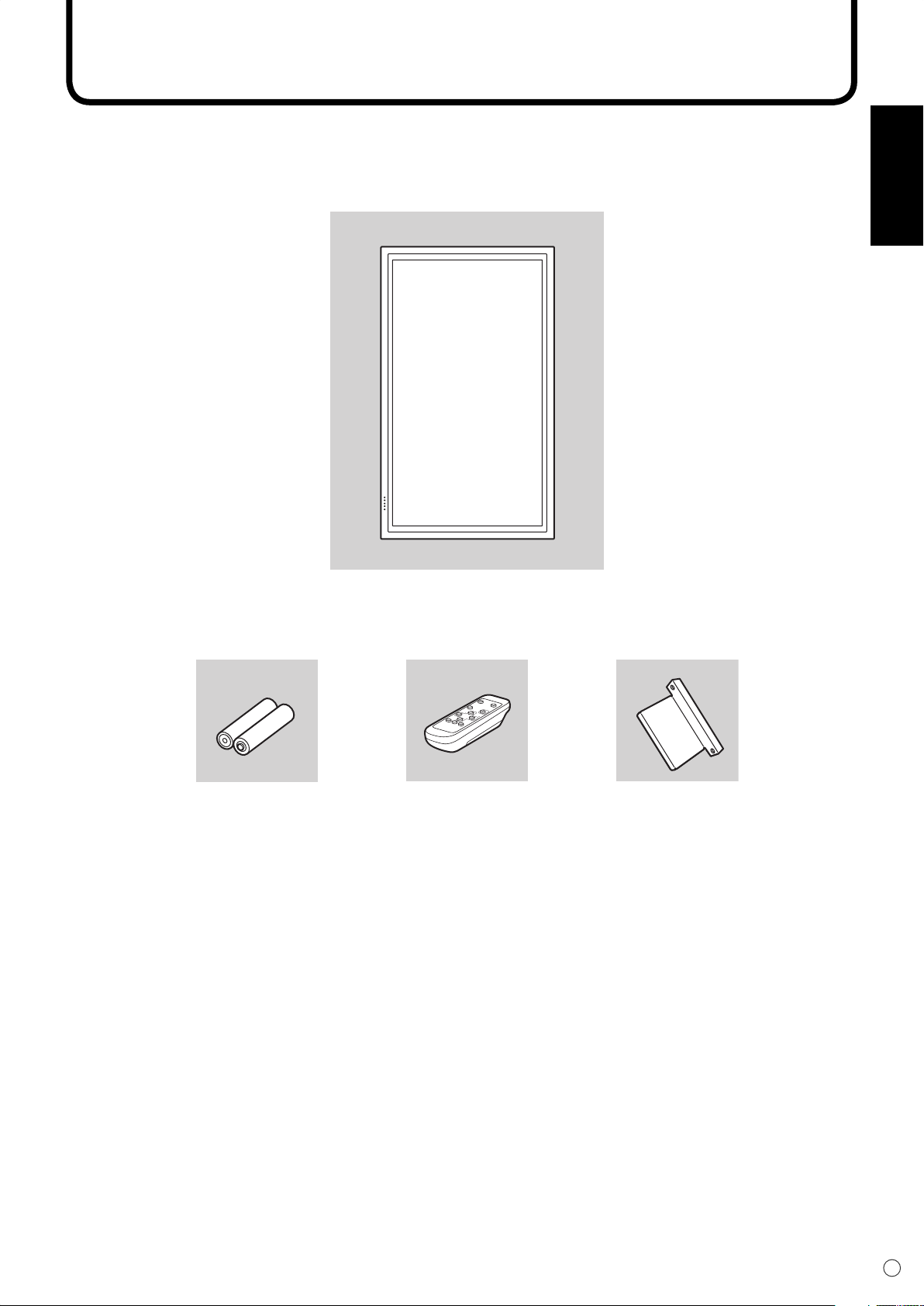
Make sure the following accessories are provided with the product.
If any component should be missing, please contact your dealer.
Liquid Crystal Display (1)
Stand hole
R-6 battery (2)
● Power cord (1)
Remote control unit (1)
● Operation manual (1)
protection cover (2)
● CD-ROM (1)
(Utility Disk for Windows)
• Sharp Corporation holds authorship rights to the Utility Disk programme. Do not reproduce it without permission.
• For environmental protection!
Do not dispose of batteries in household garbage. Follow the disposal instructions for your area.
Page 10
8
E
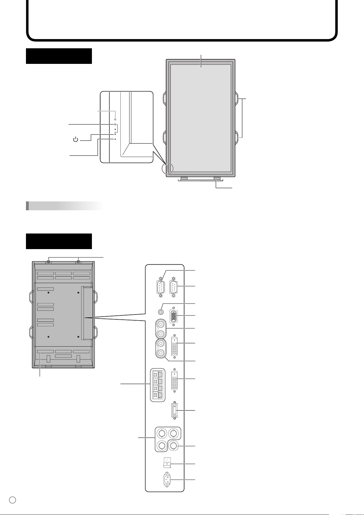
Main power switch (See page 19.)
AC input terminal (See page 14.)
Vents
Hooks
This terminal is not available.
External speaker
terminals
(See page 13.)
Composite video input terminal (See page 12.)
Audio output terminals (See page 13.)
Audio input terminals (See page 12.)
PC audio input terminal (See page 11.)
RS-232C output terminal (See page 34.)
Component video
input terminals
(See page 12.)
RS-232C input terminal (See pages 33 and 34.)
PC analogue RGB input terminal (See page 11.)
PC digital RGB (DVI-D) input terminal
(See page 11.)
PC digital RGB (DVI-D) output terminal
(See page 15.)
Part Names
Front view
Remote control sensor
(See page 18.)
Power LED
(see page 19.)
Power switch
(see page 19.)
Input switch
(see page 20.)
INPUT
LCD panel
Handles
(See page 17.)
Temporary stand
(See page 16.)
TIPS
• Use a pointed object such as a pen tip to press the switches at the front of the monitor.
• The shape of the stand may change without prior notice.
Rear view
Page 11
9
E
ENGLISH
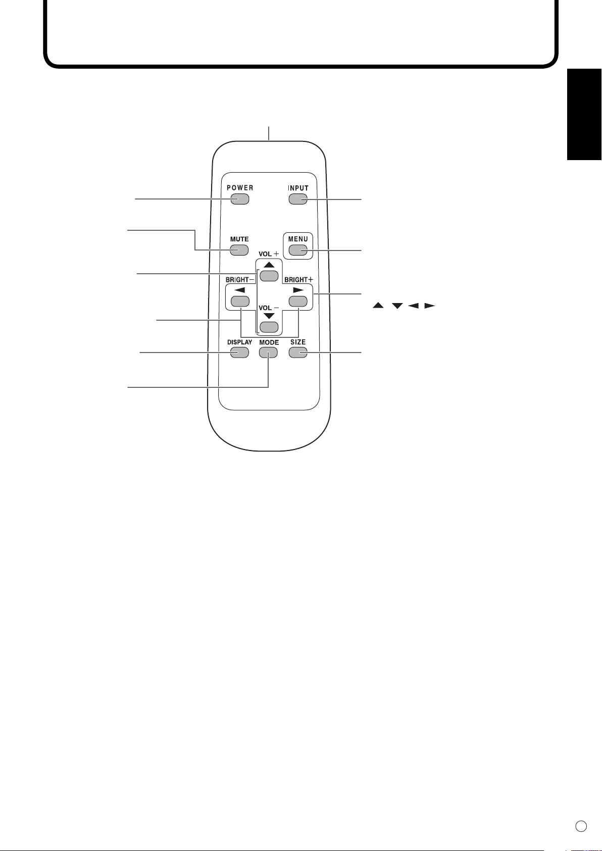
POWER button
(See page 19.)
MUTE button
(See page 20.)
DISPLAY button
(See page 21.)
MODE button
(See page 21.)
VOL +/- buttons
(See page 20.)
BRIGHT +/- buttons
(See page 20.)
INPUT button
(See page 20.)
Signal transmitter
MENU button
(See page 23.)
SIZE button
(See page 20.)
Cursor control
( / / / ) buttons (See page 23.)
Part Names
Page 12
10
E
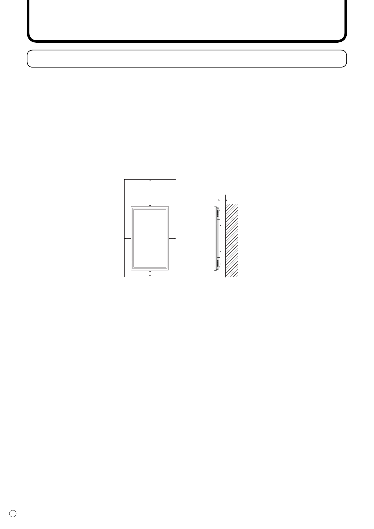
How to install the monitor
55
The Power LED must be on the lower side.
Unit: cm
5
4.5
30
Mounting precautions
• Since the monitor is heavy, consult your dealer before installation.
• Installing or moving the monitor must be done by three or more people.
•
Do not hold the LCD panel when moving the monitor. This may cause product damage, failure, or injury.
• Install the monitor with the surface perpendicular to a level surface. If necessary, limit the tilt between
0 and 20 degrees downward.
• Mounting the monitor on the wall requires special expertise and the work must be performed by an
authorized SHARP dealer. You should never attempt to perform any of this work yourself. Our company
will bear no responsibility for accidents or injuries caused by improper mounting or mishandling.
• This monitor should be used at an ambient temperature between 0°C and 40°C. Provide enough space
around the monitor to prevent heat from accumulating inside.
If it is diffi cult to provide such space because the monitor is installed inside a housing or for other
reasons, take other measures to keep the ambient temperature between 0°C and 40°C such as
installing a fan in the housing.
• This monitor must be installed in a vertical orientation only. It cannot be installed in a horizontal
orientation.
• Do not block any ventilation openings. If the temperature inside the monitor rises, this could lead to a
malfunction.
• After mounting, it is recommended to take some measures to prevent the monitor from falling down.
Secure the monitor by fastening the hooks at the top of the monitor to a wall or a pillar with strong cord
and brackets (not included).
• Do not place the monitor on a device which generates heat.
• Be sure to use a stand or a wall-mount bracket designed or designated for mounting the monitor.
• This monitor is designed to be installed on a concrete wall or pillar. Reinforced work might be necessary
for some materials such as plaster / thin plastic board / wood before starting installation. This monitor
and bracket must be installed on a wall which can endure at least 4 times or more the weight of the
monitor. Install by the most suitable method for the material and the structure.
• This monitor is fi xed to the temporary stand when shipped from the factory. Please note that this stand
is for temporary use only until the monitor is properly mounted.
Page 13
11
E
ENGLISH
Connecting Peripheral Equipment
Caution
Be sure to turn off the main power switch and disconnect the plug from the power outlet before connecting/
disconnecting cables. Also, read the manual of the equipment to be connected.
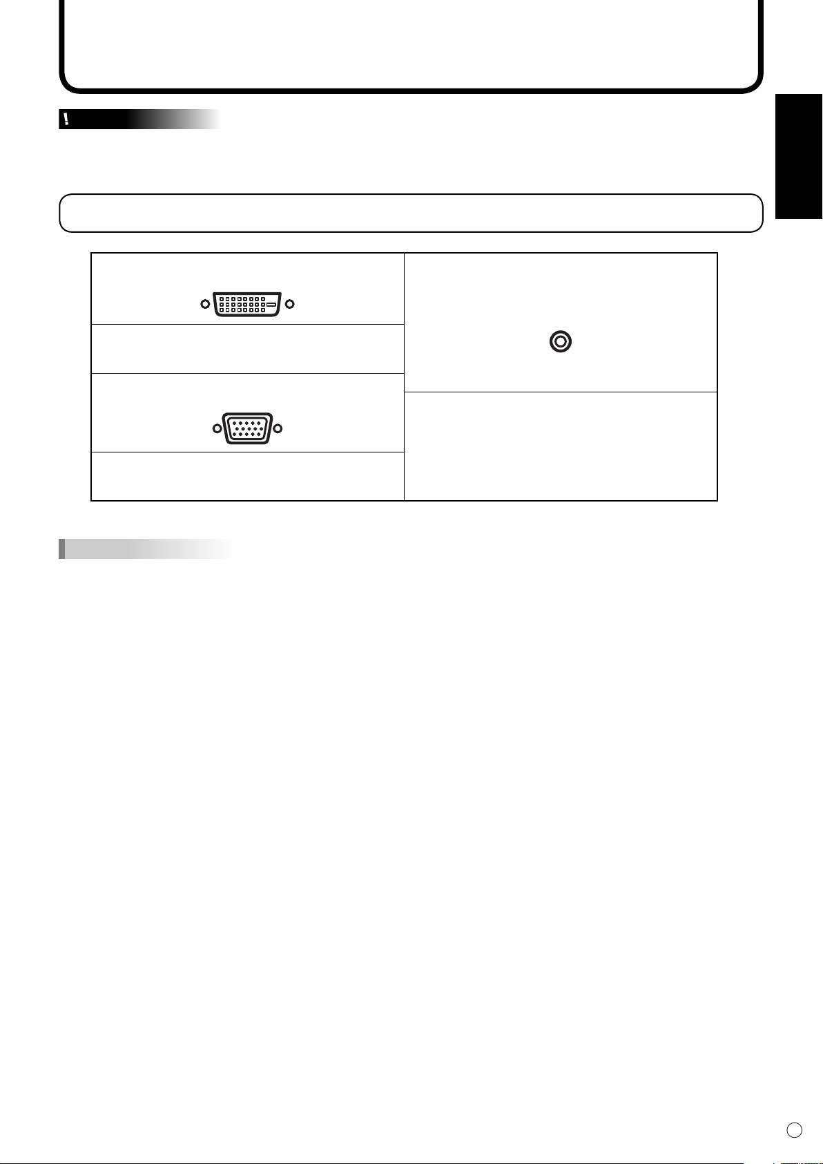
Connection with a PC
PC digital RGB input terminal
PC audio input terminal
Connect using a DVI cable (commercially
available).
PC analogue RGB input terminal
Connect using a PC audio cable
(commercially available).
Connect using a PC analogue signal cable
(commercially available).
Use a cable without resistance for the PC
audio cable.
TIPS
• For compatible signal timing (see page 50).
• The PC digital RGB input terminal can be connected with a PC which has a DVI-compliant output terminal.
(However, images may not be displayed properly depending on the computer to be connected.)
• Use the automatic screen adjustment when a PC screen is displayed for the fi rst time with the analogue RGB
connection, or when the setting of the PC is changed (see page 31).
• When the analogue RGB connection is used, the type of sync signal is automatically determined (Composite sync,
Horizontal/Vertical separate, or Sync-on-green). With some video signals, however, the sync signal may not be
detected and images may not be displayed properly.
Page 14
12
E
Connecting Peripheral Equipment
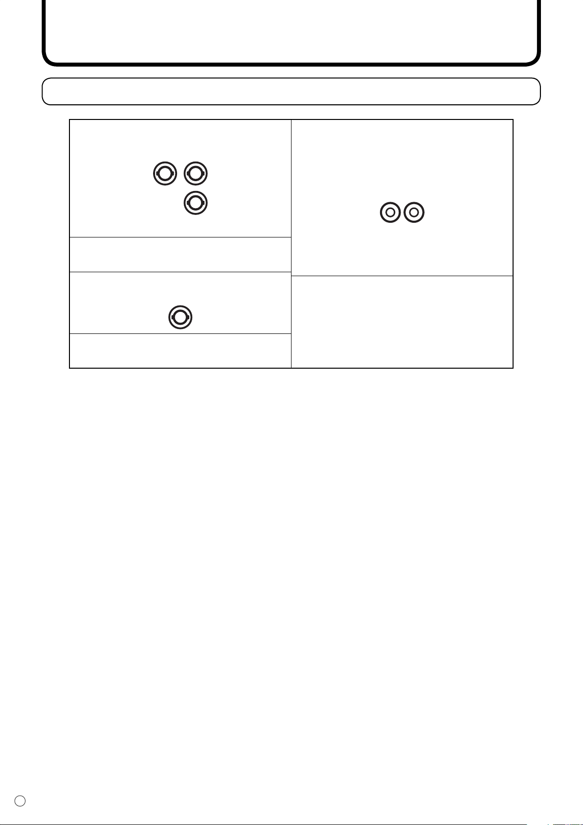
Connection with AV equipment
Component video input terminals
Y
Cb/Pb
Audio input terminals
Cr/Pr
Connect using component (BNC) cables
(commercially available).
Composite video input terminal
Connect using a video (BNC) cable
(commercially available).
Connect using audio (RCA pin) cables
(commercially available).
Page 15
13
E
ENGLISH
Connecting Peripheral Equipment
Other terminals
Audio output terminals
• Audio sounds which are input through the audio input terminal or PC audio input terminal are output.
Connect to the audio input terminals of the connected equipment using an audio (RCA) cable
(commercially available).
• The audio output varies depending on the input mode selection (see page 20).
• The volume level can be adjusted using the volume adjustment (see page 20).
PC digital RGB (DVI-D) output terminal
The video from the PC digital RGB (DVI-D) input terminal can be output to external equipment. Use this terminal
to connect multiple units in a daisy chain using digital signal (DVI) cables (commercially available). Refer to page
15 for a connection example.
RS-232C input/output terminals
You can control the monitor from a PC by connecting an RS-232C straight cable (commercially available)
between this terminal and the PC. (See pages 33 and 34.)
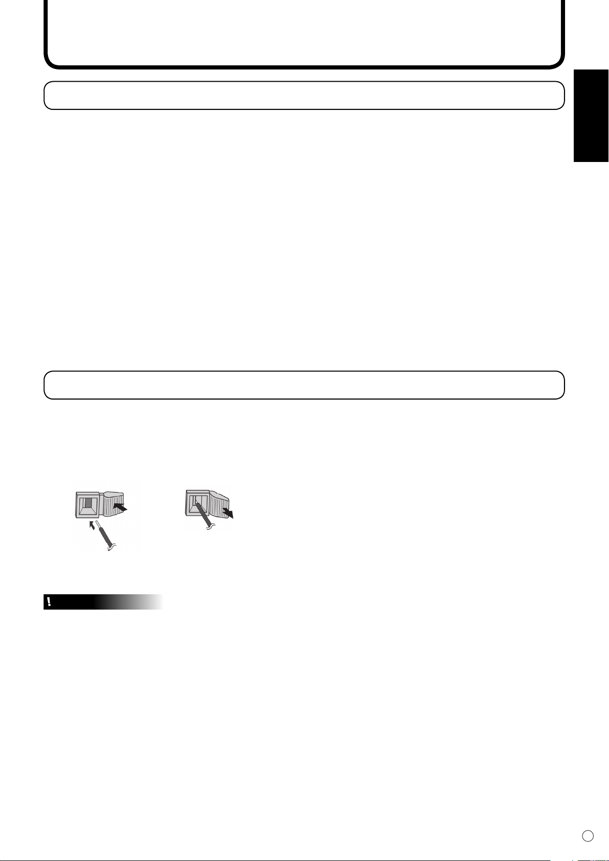
Connecting External Speakers
Be sure to use external speakers with an impedance of 6 ohms and a rated input of at least 10 W.
1. While pushing the tab, insert the tip of the cable.
2. Release the tab.
1. 2.
Caution
• Be sure to connect the + and - terminals and the left and right speakers properly.
• Avoid short circuiting the + and - terminals.
Page 16
14
E
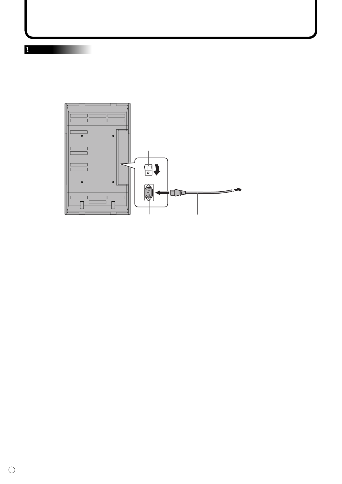
Connecting the Power Cord
Caution
Do not use a power cord other than the one supplied with the monitor.
1. Turn off the main power switch.
2. Plug the power cord (supplied) into the AC input terminal.
3. Plug the power cord (supplied) into the AC power outlet.
Main power switch
1
3
For power
outlet
Disconnecting the power cord
1. Turn off the main power switch.
2. Unplug the power cord from the AC power outlet.
2
Power cord (Supplied)AC input terminal
Page 17
15
E
ENGLISH
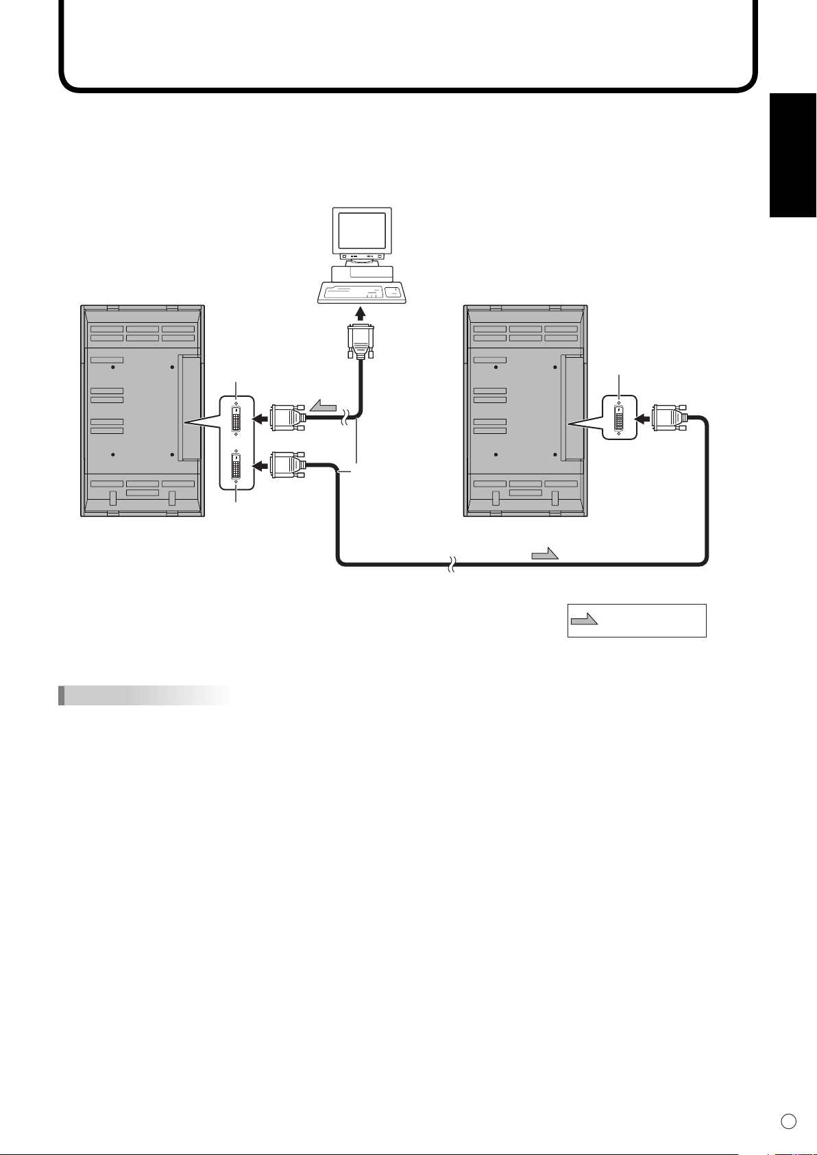
Connecting Multiple Monitors
Digital signal
(DVI) cable
(commercially
available)
To PC digital
RGB output
terminal
Shows the signal
flow
PC digital RGB
output terminal
PC digital RGB
input terminal
PC digital RGB
input terminal
▼ First monitor ▼ Second monitor
You can connect multiple monitors (up to 4 monitors) in a daisy chain by using the PC digital RGB input/
output terminals of this monitor.
Connection example
TIPS
• Multiple monitors cannot be connected in a daisy chain for audio. Connect the external audio amplifi er (commercially
available) to the audio output terminals.
• The length of the signal cables or surrounding environment may affect the image quality.
Page 18
16
E
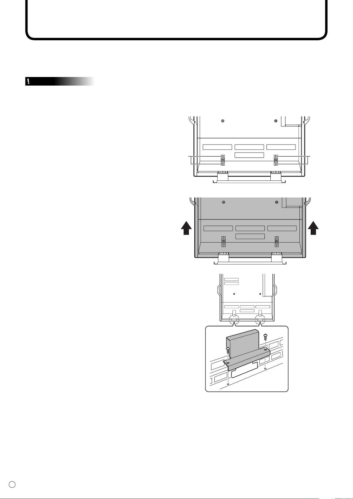
Removing the Temporary Stand
Prepare wall-hanging brackets or a stand to mount the monitor unit. Read the manual for the brackets
or stand for the proper mounting procedure. (The screw holes for mounting brackets (M10 x 4 holes) are
provided on the rear of the monitor.)
Caution
• The monitor is heavy. It must be handled by three or more people.
• This monitor is fi xed to the temporary stand when shipped from the factory. Please note that this stand is for
temporary use only until the monitor is properly mounted.
1. Hold the monitor with the handles to prevent
it from falling down, and remove the stand
fi xing screws (4).
ScrewsScrews
2. Lift the monitor by holding it with the handles
and the underside of the unit.
3. When the installation is complete, attach the
included stand hole protection covers, using
the supplied screws.
(1) Remove the screws from the monitor
unit.
(2) Secure the stand hole protection covers
with the screws removed in step (1).
• The temporary stand is specifi cally designed for this monitor. Do not use for other devices.
Page 19
17
E
ENGLISH
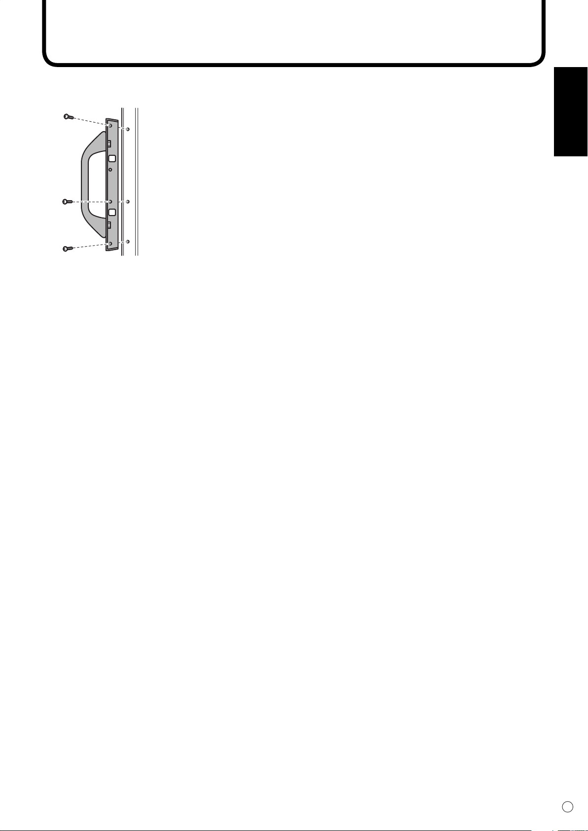
Removing the Handles
The handles are detachable.
After you removed the handles, be sure to replace the removed screws in the original holes.
Page 20
10°
5m
5m
5m
10°
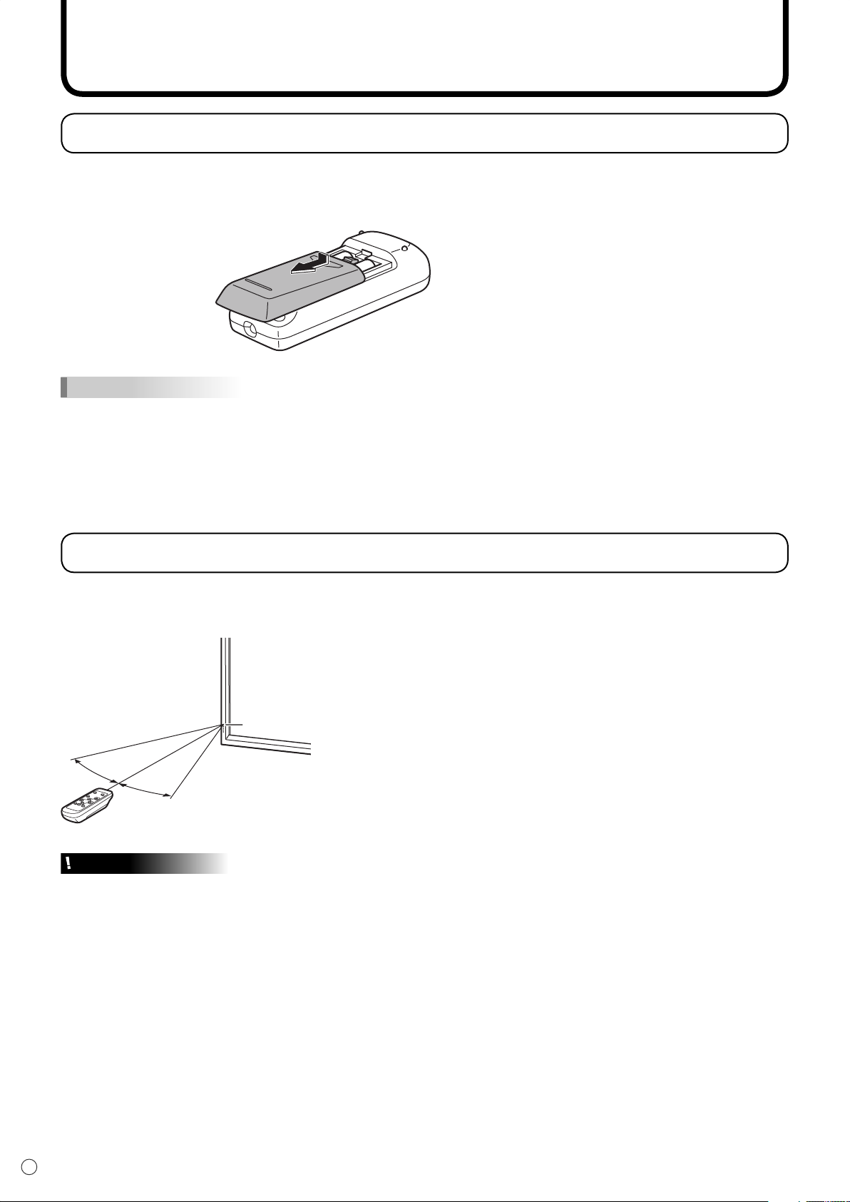
Preparing the Remote Control Unit
Setting the batteries
1. Press the cover gently and slide it in the direction of the arrow.
2. See the instructions in the compartment and put in the supplied batteries (2 R-6 batteries) with their
plus (+) and minus (-) sides oriented correctly.
3. Close the cover.
TIPS
• The supplied batteries (2 R-6 batteries) may become exhausted faster depending on the storage condition. It is
recommended that you replace them with new batteries (commercially available) earlier than specifi ed.
• If you will not use the remote control for a long time, remove the batteries.
• If the remote control does not work, even with new batteries, take the batteries out, check whether they are facing
the right way, then replace them.
• Use manganese or alkaline batteries only.
Remote control operation range
The operation range of the remote control unit is approx. 5 m at an angle of approx 10° from the centre
to the top/bottom/right/left of the remote control sensor.
Remote control sensor
Caution
• Do not expose the remote control unit to shock by dropping or stepping on it. This could lead to a
malfunction.
• Do not expose the remote control unit to liquids, and do not place it in an area with high humidity.
• The remote control unit may not work properly if the remote control sensor is under direct sunlight or
strong lighting. In such cases, change the angle of the lighting, or operate the remote control unit closer
to the remote control sensor.
• Objects between the remote control unit and the remote control sensor may prevent proper operation.
• Replace the batteries when they run low as this may shorten the remote control’s operation range.
• If a fl uorescent light is illuminated near the remote control unit, it may interfere with proper operation.
• Do not use it with the remote control of other equipment such as air conditioner, stereo components,
etc.
E
18
Page 21
Turning Power On/Off
Caution
• Turn on the monitor fi rst before turning on the PC or playback device.
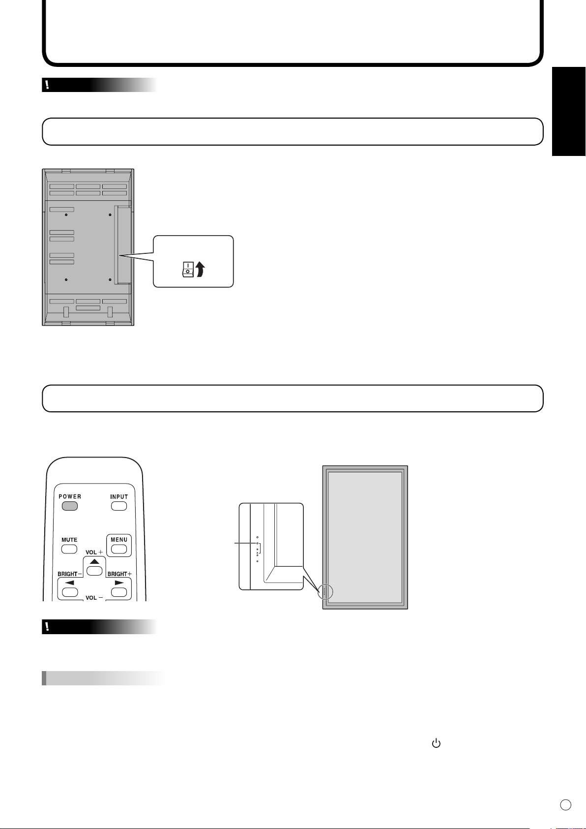
Turning on the main power
Main power switch
When the main power switch is off, the monitor cannot be turned on using the POWER button on the
remote control unit.
ENGLISH
Turning power on/off
Press the POWER button to turn the power ON/OFF.
Power “On”: Power LED lights up green.
Power “Off”: Power LED lights up orange. (Standby mode)
Power LED
INPUT
Caution
• When switching the main power switch or the POWER button off and back on, always wait for at least 5 seconds.
Rapid switching may result in a malfunction.
TIPS
• When the input mode (see page 20) is set to “DIGITAL” or “ANALOG” and there is no video signal input, the
backlight of the monitor is turned off and the monitor enters input signal waiting mode. (The power LED fl ashes
green.) If the monitor is in this mode and you press the POWER button on the remote control unit, the monitor
enters standby mode.
• If the remote control unit is not available, you can turn on/off the monitor by pressing the (power) switch on the
monitor with a pointed object.
19
E
Page 22

20
E
Basic Operation
VOLUME 15
BRIGHT 15
Generally the monitor is operated using the remote control unit.
INPUT (Input mode selection)
The input mode selection menu is displayed.
Press or to select the input terminal, and press to change
the terminal.
* If the remote control unit is not available, you can select the input
terminal by pressing the input switch on the monitor with a pointed object.
(See page 8)
DIGITAL
ANALOG
COMPONENT
VIDEO
MUTE
Turns off the volume temporarily.
Press the MUTE button again to turn the sound back to the previous level.
MENU
Displays and turns off the menu screen (see page 23).
PC digital RGB input terminal
PC analogue RGB input terminal
Component video input terminal
Composite video input terminal
Video
Audio
PC audio input terminal
Audio input terminals
VOL +/- (Volume adjustment)
Pressing or displays the VOLUME menu when the menu screen
is not displayed.
Press to increase the volume, and to decrease the volume.
* If you do not press any buttons for about 4 seconds, the VOLUME menu
automatically disappears.
BRIGHT +/- (Backlight adjustment)
Pressing or displays the BRIGHT menu when the menu screen is
not displayed.
Press to increase the brightness of the screen, and to decrease
the brightness of the screen.
* If you do not press any buttons for about 4 seconds, the BRIGHT menu
automatically disappears.
SIZE (Screen size selection)
Each time you press this button, the screen size changes in the following
order (see pages 21 and 22):
• WIDE → ZOOM 1 → ZOOM 2 → NORMAL → DotbyDot → WIDE...
Page 23
21
E
ENGLISH
Basic Operation
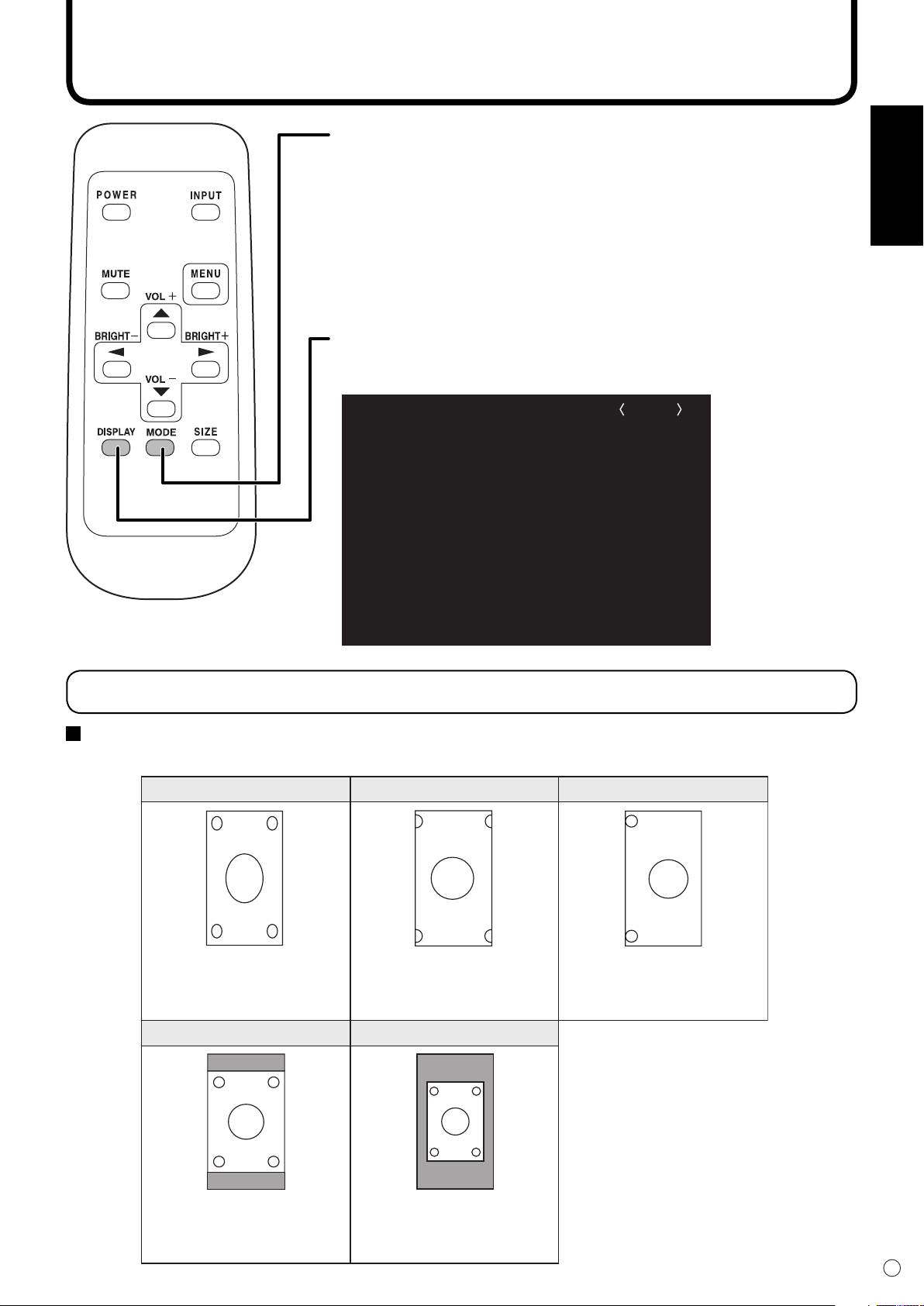
MODE (Screen mode selection)
Each time you press this button, the screen mode changes in the following
order:
STD (Standard) → OFFICE *1 → VIVID
•
→ sRGB *2 →
STD...
*1 Display brightness is lowered. (This mode saves power.)
*2 When the input mode is DIGITAL/ANALOG.
sRGB is international standard of colour representation specifi ed by IEC
(International Electrotechnical Commission).
Colour conversion is made in taking account of liquid crytal’s characteristics and
represents colour tone close to its original image.
DISPLAY
Displays monitor information. The display disappears when this button is
pressed again or disappears automatically after approximately 15 seconds.
INFORMATION ANALOG
INPUT MODE
SIZE
MODE
BRIGHT
VOLUME
OFF TIMER
ID No.
MODEL
S/N
:
:
:
:
:
:
:
:
:
ANALOG
WIDE
OFFICE
23
15
10:38
18
PN-655RE
XXXXXXXXX
1920x1080
V: 60 Hz H: 66.3 kHz
Switching the screen size
Switching the screen size (When the input mode is DIGITAL/ANALOG)
Even when the screen size is changed, the display may remain the same depending on the input signal.
WIDE ZOOM 1 ZOOM 2
Displays image so it fills the
entire screen.
NORMAL
An image with a 4:3 aspect ratio is
enlarged to fill the entire screen
without changing the aspect ratio. The
edges of the image may be cut off.
Use this size if ZOOM 1 cuts
off the subtitles.
DotbyDot
Displays image so it fills the
screen without changing the
aspect ratio of the input
signals.
Displays the dots of the signals
input from the connected PC as
the corresponding dots on the
screen. *
* With a monitor with a screen
resolution of 1600 x 1200,
selecting DotbyDot displays the
NORMAL screen.
Page 24
22
E
WIDE ZOOM 1 ZOOM 2
DotbyDot
NORMAL
Displays the entire image of the
aspect ratio of 4:3 without
changing the aspect ratio.
An image with a 4:3 aspect
ratio is stretched to fill the
entire screen.
Use this size if ZOOM 1 cuts
off the subtitles.
An image with a 4:3 aspect
ratio is enlarged to fill the
entire screen without changing
the aspect ratio. The edges of
the image may be cut off.
Displays the dots of the input
signals as the corresponding
dots on the screen.*
Basic Operation
Switching the screen size (When the input mode is COMPONENT/VIDEO)
Even when the screen size is changed, the display may remain the same depending on the input signal.
* If “DotbyDot” is selected in the conditions below, the image quality cannot be changed by
adjusting the value of “SHARPNESS” from the VIDEO ADJUSTMENT menu.
· When the input mode is VIDEO
· When the input mode is COMPONENT and images of 480i or 480p are displayed
TIPS
• Using this monitor’s screen-size switching or dual-screen display functions to compress or expand the screen for
commercial or public viewing in establishments like cafes or hotels may infringe on the rights of the creators, as
protected by Copyright Law, so please be careful.
• When “Enlarge” is set, the screen size is fi xed to “WIDE” mode.
• When dual-screen display is selected, the screen size cannot be changed.
• When using the screen-size switching function of this monitor, the appearance of the original video may change if
you select a screen size with a different aspect ratio than the original image (e.g. TV broadcast or video input from
external equipment). Please consider this point when selecting the screen size.
• When an ordinary non-wide image (4:3) is viewed with the whole screen using the screen-size switching function
of this monitor, the edge of the image may be lost or appear distorted. If you wish to respect the creator’s
intentions, set the screen size to “NORMAL”.
• When playing commercial software, parts of the image (like subtitles) may be cropped. In this case select the
optimal screen size using the screen-size switching function of this monitor. With some software, there may
be noise or distortion at the edges of the screen. This is due to the characteristics of the software, and is not a
malfunction.
• Depending on the original image size (e.g. CinemaScope size), black bands may remain at the edges of the
screen.
Page 25
23
E
ENGLISH
Menu Items
MANUAL
CLOCK
PHASE
H-POS
V-POS
AUTO
RESET
127
77
134
113
1920x1080
ANALOGADJUSTMENT
V: 60 Hz H: 66.3 kHz
MANUAL
BLACK LEVEL
CONTRAST
AUTO
1920x1080
15
15
GAIN CONTROL ANALOG
V: 60 Hz H: 66.3 kHz
Menus can be displayed on the screen to enable video and audio adjustment and the setting of various
functions using the remote control unit. For more information, refer to the pages where each topic is
explained.
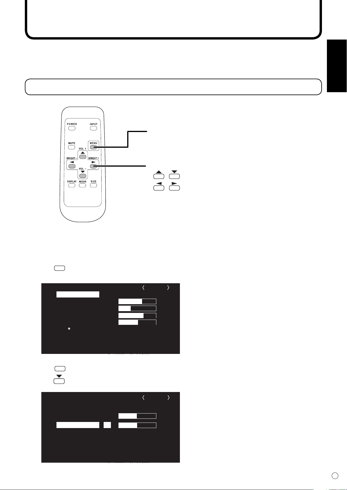
Displaying the menu screen
MENU button
• Displays and turns off the menu screen.
• Switches menu screens.
Cursor control (UP/DOWN/LEFT/RIGHT)
• / : Selects a desired item on the screen.
• / : Adjusts the selected item.
Example of menu operation: Adjusting CONTRAST in the GAIN CONTROL
menu.
1.
Press
2.
Press
3.
Press to select CONTRAST.
MENU
to display the menu screen.
MENU
to display the GAIN CONTROL menu.
Page 26
24
E
Menu Items
MANUAL
BLACK LEVEL
CONTRAST
AUTO
1920x1080
15
25
GAIN CONTROL ANALOG
V: 60 Hz H: 66.3 kHz
MANUAL
BLACK LEVEL
CONTRAST
AUTO
1920x1080
15
15
GAIN CONTROL ANALOG
V: 60 Hz H: 66.3 kHz
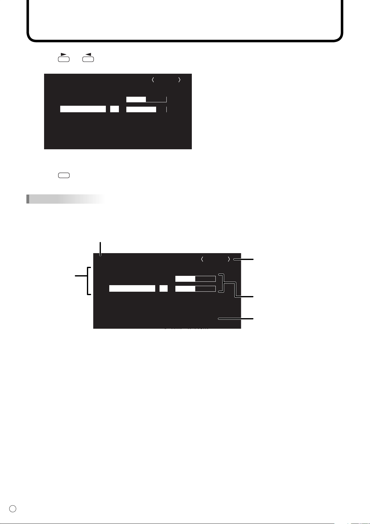
4.
Press (or ) to adjust the setting.
5.
Press
MENU
to close the menu screen.
The menu screen will close automatically if no operation is performed for about 15 seconds.
TIPS
• The displayed menu screen will differ depending on the input mode selection.
Menu screen display
Name of the menu
Displays the input mode
currently being selected.
Names of setting
items and their status
The currently selected item will
be highlighted.
Displays the screen
resolution, vertical frequency,
horizontal frequency, or type
of signal of the current input
signal.
Yellow: Current setting
Blue: Selectable items
Grey: Item that cannot be selected (e.g. Function not supported by the current input signal)
Page 27
25
E
ENGLISH
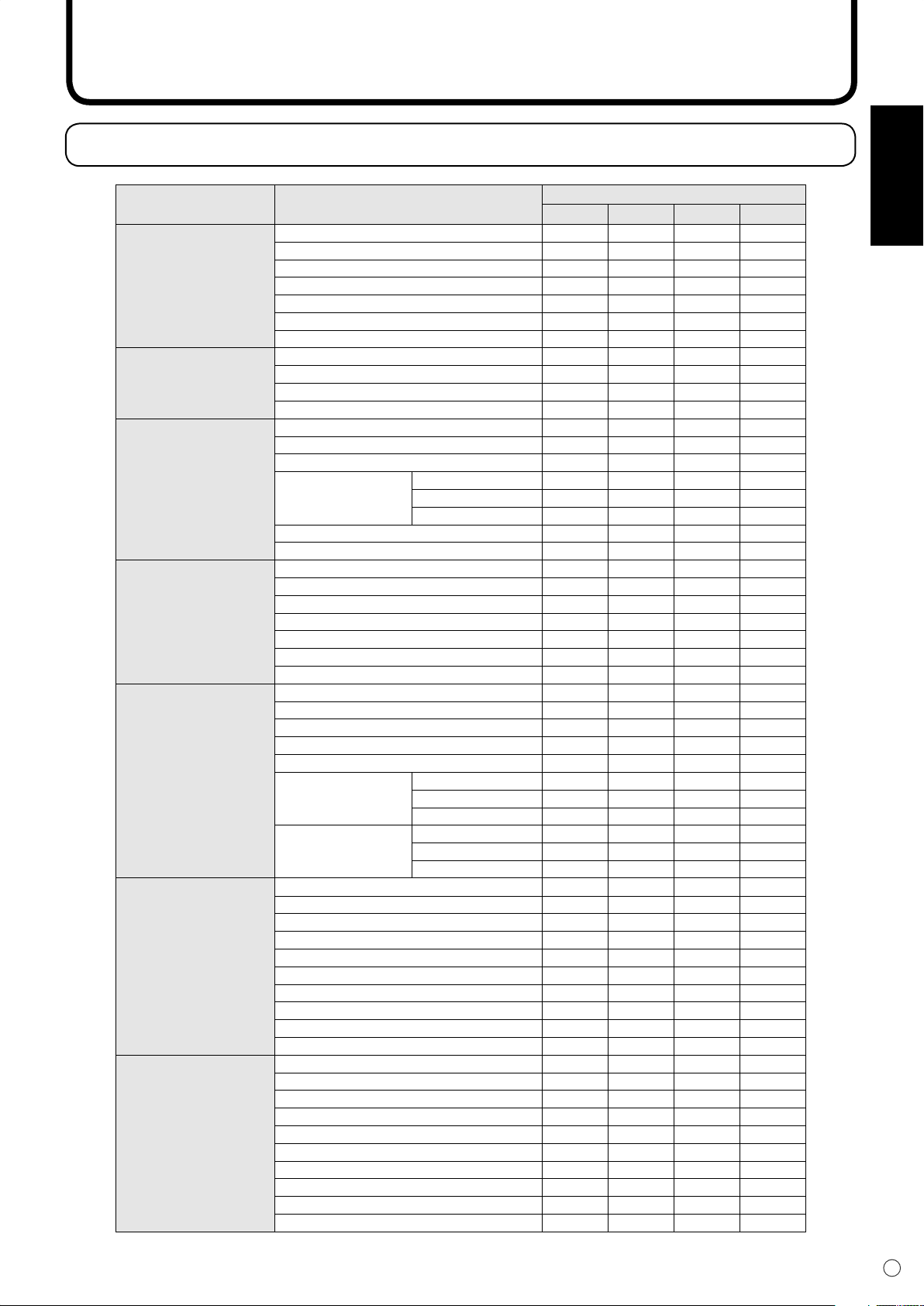
Menu Option Reference Chart
Menu Items
Menu Item
MANUAL ― Yes ― ―
AUTO ― Yes ― ―
ADJUSTMENT
(See page 26.)
GAIN CONTROL
(See page 26.)
COLOR CONTROL
(See page 26.)
VIDEO ADJUSTMENT
(See page 27.)
MODE SELECT 1
(See page 27.)
MODE SELECT 2
(See page 27.)
MODE SELECT 3
(See page 28.)
CLOCK ― Yes ― ―
PHASE ― Yes ― ―
H-POS ― Yes ― ―
V-POS ― Yes ― ―
RESET ― Yes ― ―
MANUAL ― Yes ― ―
AUTO ― Yes ― ―
BLACK LEVEL Yes Yes ― ―
CONTRAST Yes Yes ― ―
WHITE BALANCE Yes Yes ― ―
THRU Yes ― ― ―
PRESET Yes Yes ― ―
USER
COPY TO USER Yes Yes ― ―
GAMMA Yes Yes ― ―
CONTRAST ― ― Yes Yes
BLACK LEVEL ― ― Yes Yes
TINT ― ― Yes Yes
COLORS ― ― Yes Yes
SHARPNESS ― ― Yes Yes
WHITE BALANCE ― ― Yes Yes
GAMMA ― ― Yes Yes
480 LINES ― Yes ― ―
768 LINES ― Yes ― ―
BEZEL Yes Yes ― ―
ENLARGE Yes Yes ― ―
ENLARGE-POS Yes Yes ― ―
MULTI ZOOM
AUDIO
OFF TIMER Yes Yes Yes Yes
OSD H-POSITION Yes Yes Yes Yes
OSD V-POSITION Yes Yes Yes Yes
LANGUAGE Yes Yes Yes Yes
SCREEN MOTION Yes Yes Yes Yes
MOTION TIME1 Yes Yes Yes Yes
MOTION TIME2 Yes Yes Yes Yes
POWER ON DELAY Yes Yes Yes Yes
ID No. SET Yes Yes Yes Yes
COLOR SYSTEM Yes Yes Yes Yes
PIP MODES Yes Yes Yes Yes
PIP SIZE Yes Yes Yes Yes
PIP H-POS Yes Yes Yes Yes
PIP V-POS Yes Yes Yes Yes
PIP BLEND Yes Yes Yes Yes
PIP SOURCE Yes Yes Yes Yes
SOUND CHANGE Yes Yes Yes Yes
MAIN POS Yes Yes Yes Yes
PbyP2 POS Yes Yes Yes Yes
AUTO OFF Yes Yes Yes Yes
Input Mode
DIGITAL
R-CONTRAST Yes Yes ― ―
G-CONTRAST Yes Yes ― ―
B-CONTRAST Yes Yes ― ―
IMAGE ZOOM Yes Yes ― ―
H-POS Yes Yes ― ―
V-POS Yes Yes ― ―
TREBLE Yes Yes Yes Yes
BASS Yes Yes Yes Yes
BALANCE Yes Yes Yes Yes
ANALOG
COMPONENT
VIDEO
Page 28
26
E
Menu Items
Menu item details
The menu will differ depending on the input mode.
ADJUSTMENT (ANALOG)
[MANUAL / AUTO]
Adjusts CLOCK, PHASE, H-POS (horizontal positioning),
and V-POS (vertical positioning). When Windows OS is
used, the adjustment patterns in the supplied CD-ROM can
be used. (See page 31.)
MANUAL ·············The CLOCK, PHASE, H-POS, and V-POS
are manually adjusted.
AUTO ··················The CLOCK, PHASE, H-POS, and V-POS
are automatically adjusted.Use this
automatic adjustment when you use the
PC analogue RGB input terminal to display
a PC screen for the fi rst time or when you
change the setting of the PC. (See page
31.)
[CLOCK]
Adjusts frequency for sampling clock for applicable video.
Adjust when there is fl ickering in the form of horizontal
stripes.When using the adjustment pattern (see page 31),
make adjustments so that no horizontal stripe noise appears
in it.
[PHASE]
Adjusts sampling clock phase for applicable video. Useful
when small characters appear with low contrast and/or there
are fl ickers at corners. When using the adjustment pattern
(see page 31), make adjustments so that no vertical stripe
noise appears in it.
Adjustments to PHASE should be made only after CLOCK
has been correctly set.
[H-POS]
Adjust the horizontal position of the image.
[V-POS]
Adjust the vertical position of the image.
[RESET]
When the
ADJUSTMENT menu items are reset to the factory-settings.
button is pressed, all values for the
GAIN CONTROL (DIGITAL/ANALOG)
[MANUAL / AUTO] (ANALOG)
Adjusts BLACK LEVEL and CONTRAST.
MANUAL ·············The BLACK LEVEL and CONTRAST can
be adjusted manually by checking the
adjustment pattern. (See page 31.)
AUTO ··················The BLACK LEVEL and CONTRAST are
automatically adjusted.
[BLACK LEVEL]
Adjusts the entire brightness of the video signals.
[CONTRAST]
Adjusts the brightness of the image.
COLOR CONTROL (DIGITAL/ANALOG)
[WHITE BALANCE (colour temperature)]
THRU ··················Displays the input signal level as is.
(through) (for DIGITAL only)
PRESET ·············Allows selection from the preadjusted
settings. (For a guide to the colour
temperatures of the adjustment values,
see page 29.)
USER··················Allows adjustment of
R-CONTRAST (red contrast),
G-CONTRAST (green contrast), and
B-CONTRAST (blue contrast).
[R-CONTRAST]
Adjusts red component.
[G-CONTRAST]
Adjusts green component.
[B-CONTRAST]
Adjusts blue component.
[COPY TO USER]
SET ·····················Copies the value set for PRESET to the
USER setting.
[GAMMA]
Select a gamma value.
Page 29
27
E
ENGLISH
Menu Items
VIDEO ADJUSTMENT
(COMPONENT/VIDEO)
[CONTRAST]
Adjusts bright parts of the image.
[BLACK LEVEL]
Adjusts the entire brightness of the video signals.
[TINT]
Adjusts the hue. Selecting + changes the colour towards
green, and selecting - changes it towards magenta.
[COLORS]
Adjusts the colour intensity.
[SHARPNESS]
Adjusts the sharpness of the image.
[WHITE BALANCE]
Allows selection from the preadjusted settings. (For a guide
to the colour temperatures of the adjustment values, see
page 29.)
[GAMMA]
Select a gamma value.
MODE SELECT 1
[480 LINES] (ANALOG)
Manually selects input resolution.
[768 LINES] (ANALOG)
Manually selects input resolution.
[BEZEL] (DIGITAL/ANALOG)
Sets the frame width of the display when the enlargement
function is used.
[ENLARGE] (DIGITAL/ANALOG)
Sets the number of screen splits used for the enlargement.
(See page 30.)
[ENLARGE-POS] (DIGITAL/ANALOG)
Specify the split screen to be displayed when the
enlargement function is used. (See page 30.)
[MULTI ZOOM] (DIGITAL/ANALOG)
Adjusts the enlarged screen.
Pressing
IMAGE ZOOM ····Adjusts the scale of enlargement.
H-POS ················Adjusts the horizontal position.
V-POS ················Adjusts the vertical position.
[AUDIO]
Adjust the volume of the sound output from the speaker.
Pressing
TREBLE ·············Adjusts the volume of treble-level sound.
BASS ··················Adjusts the volume of bass-level sound.
BALANCE ···········Adjusts the balance of the audio sound
displays the next menu.
displays the next menu.
between right and left.
MODE SELECT 2
[OFF TIMER]
Set the time until the monitor turns off (enters standby mode)
between 0 and 23 in units of one hour.
This function is disabled when 0 is specifi ed.
[OSD H-POSITION]
Adjusts the horizontal display position of menu screen.
[OSD V-POSITION]
Adjusts the vertical display position of menu screen.
[LANGUAGE]
Sets the display language for the menu screen.
Pressing
[SCREEN MOTION]
[MOTION TIME 1]
[MOTION TIME 2]
When SCREEN MOTION is switched on, the screen image
moves vertically and horizontally to reduce the rate of
residual image formation.
When the time specifi ed in MOTION TIME 1 elapses, the
screen image is moved vertically and horizontally for a
certain period of time at the interval specifi ed in MOTION
TIME 2. After the movement stops and the time specifi ed
in MOTION TIME 1 elapses again, SCREEN MOTION
activates again.While the screen image is moving, the edges
of the screen may be hidden.
[POWER ON DELAY]
You can delay the screen display after the monitor is turned
on. The period can be set up to 60 seconds in units of
one second. When this function is activated, the power
LED fl ashes in orange. This function is disabled when 0 is
specifi ed.
[ID No. SET]
Assigns ID numbers to monitors connected in a daisy chain
(see page 36), using RS-232C cables.
The numbers 1 to 255 are available for ID numbers. If “0” is
set, the system regards this as the state where no ID number
is set.
[COLOR SYSTEM]
Select the colour system of the AV equipment which is
connected to the composite video input terminal. (AUTO /
PAL / PAL-60 / SECAM / NTSC3.58 / NTSC4.43)
When AUTO is selected, the colour system is automatically
set according to the input signal.
displays the next menu.
Page 30
28
E
Menu Items
MODE SELECT 3
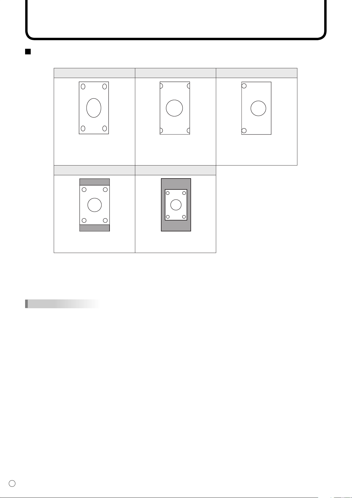
[PIP MODES] (See page 29)
Sets the display method.
OFF ····················Displays one screen.
PIP ······················Displays a sub screen inside a main
screen.
PbyP ···················Displays a main screen and a sub screen
in a line.
PbyP2 ·················Displays a main screen which measures
1280 pixels in the longest direction and a
sub screen in a line.
[PIP SIZE]
Sets the size of the sub screen in PIP mode.
[PIP H-POS]
Adjusts the horizontal position of the sub screen in PIP
mode.
[PIP V-POS]
Adjusts the vertical position of the sub screen in PIP mode.
[PIP BLEND]
In PIP mode, use this menu item to display the sub screen
transparently.
[PIP SOURCE]
Selects the signal input of the sub screen in PIP, PbyP, or
PbyP2 mode.
[SOUND CHANGE]
Sets the sound which is output in PIP, PbyP, or PbyP2 mode.
If the main screen is displayed as a full screen by the AUTO
OFF function, the sound for the main screen is output even
when the sound for the sub screen is specifi ed.
[MAIN POS]
Sets the position of the main screen in PbyP or PbyP2 mode.
[PbyP2 POS]
Sets the position of the sub screen in PbyP2 mode.
[AUTO OFF]
Sets the display method when no signals for the sub screen
are input in PIP, PbyP, or PbyP2 mode.
AUTO ··················Displays the main screen as a full screen.
MANUAL ·············Displays a main screen and a black sub
screen.
TIPS
• When WHITE BALANCE is set to THRU, BLACK
LEVEL, CONTRAST and GAMMA cannot be set.
• When MODE is set to sRGB or VIVID, COLOR
CONTROL cannot be set. (DIGITAL/ANALOG)
• When MODE is VIVID, WHITE BALANCE and
GAMMA cannot be set. (COMPONENT/VIDEO)
Page 31

29
E
ENGLISH
PIP
Example Example Example
PbyP PbyP2
A sub screen is displayed
inside a main screen.
Displays a main screen
which measures 1280 pixels
in the longest direction and
a sub screen in a line.
A main screen and a sub
screen are displayed in a
line.*
Main screen
Sub
screen
Main
screen
Sub
screen
Main screen
Sub
screen
Menu Items
Guide to the colour temperatures of the adjustment values
The following is a guide to the colour temperatures of the respective adjustment values for WHITE
BALANCE.
Factory-adjusted value is “13” (approx. 9,000K).
Adjustment
value
Colour
temperature (K)
Adjustment
value
Colour
temperature (K)
Adjustment
value
Colour
temperature (K)
15 app. 10,000 10 app. 7,500 5 app. 5,000
14 app. 9,500 9 app. 7,000 4 app. 4,500
13 app. 9,000 8 app. 6,500 3 app. 4,000
12 app. 8,500 7 app. 6,000 2 app. 3,500
11 app. 8,000 6 app. 5,500 1 app. 3,000
Dual screen display
You can display the screens of the PC input signal (DIGITAL/ANALOG) and AV input signal
(COMPONENT/VIDEO) simultaneously.
Set this function with “PIP MODES” in the MODE SELECT 3 menu. (See page 28.)
• The currently selected input signal is displayed on the main screen.
• You cannot simultaneously display the screens of signals of the same type, such as two types of PC
input signals or two types of AV input signals.
* When you select “COMPONENT” on the PbyP main screen and the 1080i video
signal is input, the image quality cannot be changed even if you adjust the value for
“SHARPNESS” on the VIDEO ADJUSTMENT menu.
TIPS
• You might infringe on a copyright of the author which is protected by copyright law when you display the images of
the computer screen and television/VCR simultaneously for profi t-making or to show the image to the public.
• The screen size for dual-screen display is the same as the screen size for single-screen display. The DotbyDot
screen is displayed in NORMAL size except when it is set as the PIP main screen.
• When dual-screen display is selected, the SCREEN MOTION function is disabled.
• When dual-screen display is selected, the screen cannot be enlarged.
Page 32

30
E
0
1
2
3
4
5
6
7
8
0
1
2
4
5
6
8
9
10
3
711
12
13
14
15
4 screen monitor set-up
16 screen monitor set-up
0
1
3
2
9 screen monitor set-up
Menu Items
Enlarge
You can set up 4, 9, or 16 monitors and integrate them into a single large screen to display video. Each
monitor displays an enlargement of 1/4, 1/9, or 1/16 of the original image.
TIPS
• AV input signals (COMPONENT/VIDEO) cannot be used for the Enlarge function.
• To integrate 9 or more monitors using DIGITAL signals, a splitter for the video signal (commercially available) is
required.
• When connected in ANALOG mode, a splitter for the video signal (commercially available) is required.
• When Enlarge is used, the SCREEN MOTION function is disabled.
Page 33

31
E
ENGLISH
Menu Items
Adjustments for PC screen display
When you use the PC analogue RGB input terminal to display a PC screen for the fi rst time, or when you
change the setting of the PC, you need to perform the automatic adjustment from the ADJUSTMENT
menu. (See page 26.)
Before making adjustments in the ADJUSTMENT menu or GAIN CONTROL menu, display an image to
brighten the entire screen.
If you are using a Windows PC, use the adjustment pattern on the supplied CD-ROM.
Retrieving the adjustment pattern
1. Connect the monitor and computer.
2. Load the supplied CD-ROM into the computer’s CD-ROM drive.
3. Open the CD-ROM in [My Computer].
4. Double-click [Adj_uty.exe] to start the adjustment programme.
The adjustment pattern will appear. Adjust the screen automatically or manually.
5. When adjustment is fi nished, press the [Esc] on the computer’s keyboard to quit the adjustment
programme.
6. Eject the CD-ROM from the CD-ROM drive.
TIPS
• If the display mode on the computer you are using is 65,000 colours, the colour levels in the colour pattern may
appear differently or greyscale may appear to be coloured. (This is due to the specifi cations of the input signal and
is not a malfunction.)
Automatic adjustment procedure
1. Set the input mode to “ANALOG” and display the adjustment pattern above.
2. Press
3. Press
4. Press
TIPS
• If the screen cannot be adjusted properly with one automatic adjustment, repeat the automatic adjustment two or
three times. Try manual adjustment if necessary.
MENU
and display the ADJUSTMENT menu.
and select “AUTO”. The automatic adjustment is complete in several seconds.
MENU
six times to close the menu screen.
Page 34

Initialisation (Reset)/Functional Restriction Setting
ALL RESET
ADJUSTMENT LOCK
OSD DISPLAY
LED
RS-232C
OFF
OFF
OFF
LOCKED
ALL RESET
1 2
ON
ON
UNLOCKED
FUNCTION 1
MENU
You can return contrast, image quality, and other settings to their factory-preset values, specify whether
power LEDs lights, and enable control via RS-232C (see page 33) among other functions.
1.
After pressing
SIZE
for about 5 seconds, press , , , and in that order.
The FUNCTION 1 screen will appear.
2.
Select and set the items you want.
[ALL RESET]
Resets the monitor settings other than the POWER ON DELAY settings to the factory default settings.
After initialisation (reset), turn the main power switch off and then back on.
[ADJUSTMENT LOCK]
Disables operation.
OFF ···············Enables operation.
1 ····················Disables operation other than turning power on/off and displaying the “FUNCTION 1”
screen.
2 ····················Disables operation other than displaying the “FUNCTION 1” screen.
[OSD DISPLAY]
Hides/shows menus. The FUNCTION 1 screen cannot be hidden.
OFF ···············Hides the menus.
ON ·················Displays the menus.
[LED]
Specifi es whether to light power LEDs.
OFF ···········Does not light power LEDs.
ON ············· Lights power LEDs.
[RS-232C]
Specifi es whether to allow control via RS-232C (see page 33).
LOCKED ········Disables control via RS-232C.
UNLOCKED···Enables control via RS-232C.
E
32
3.
Press
to return to the normal screen.
Page 35

Controlling the Monitor with a PC
RS-232C straight cable
(commercially available)
To COM port
To RS-232C
input terminal
▼ PC
RS-232C
input terminal
You can control this monitor from a PC via RS-232C (COM port) on the PC. You can also connect
multiple monitors via a daisy chain by using a PC. By assigning ID numbers to each monitor (see page
36), you can make input mode selection/adjustment or can check the status of a specifi c monitor.
PC connection
One-to-one connection with a PC......
Connect with RS-232C straight cable between the PC’s COM port (RS-232C connector) and the
RS-232C input terminal of the monitor.
Basic operation
ENGLISH
33
E
Page 36

34
E
Controlling the Monitor with a PC
RS-232C straight cable (commercially available)
▼ First monitor ▼ Second monitor
▼ PC
RS-232C
straight cable
(commercially available)
To COM port
RS-232C
output terminal
RS-232C
input terminal
RS-232C
input terminal
RS-232C
output terminal
Daisy chain connection from a single PC......
Advanced operation
Connect with RS-232C straight cable between the PC’s COM port (RS-232C connector) and the
RS-232C input terminal of the fi rst monitor. Next, connect RS-232C straight cable to the fi rst
monitor’s RS-232C output terminal and to the second monitor’s RS-232C input terminal. Connect in
the same way to the third and subsequent monitors. Up to 20 monitors can be connected. (Depending
on the length of the cable used and the surrounding environment.)
Communication conditions
Set the RS-232C communication settings on the PC to match the monitor’s communication settings as
follows:
Baud rate 9,600 bps Stop bit 1 bit
Data length 8 bits Flow control None
Parity bit None
Page 37

35
E
ENGLISH
Controlling the Monitor with a PC
Communication procedure
Basic operation
<Command format>
When a command is sent from the PC to the monitor, the monitor operates according to the received
command and sends a response message to the PC.
Return code
C1 C2 C3 C4 P1 P2 P3 P4
Command field
(4 prescribed
alphanumerical
characters)
Example: VOLM0030
VOLM 30 (“ ” indicates a space.)
* Be sure to input 4 characters for the parameter. Pad with spaces if necessary.
Wrong: VOLM30
Right: VOLM 30 (“ ” indicates a space. “ ” is the return code (0DH, 0AH or 0DH).)
Parameter field
(4 character string
comprised of:
0-9, +, -, space, ?)
When inputting a negative value, specify a numerical value in three digits.
Example: AUTR-009
To use the six-digit command (MPOS), use a six-digit numerical value without spaces in between.
Example: MPOS010097
If a command has “R” listed for “DIRECTION” in the “RS-232C command table” on page 42, the current
value can be returned by using “?” as the parameter.
Example: 1. If an ID number has not been set:
VOLM???? ← From PC to monitor (How much is current volume setting?)
30 ← From monitor to PC (Current volume setting: 30)
2. If an ID number has been assigned (For example, ID number = 1)
VOLM ? ← From PC to monitor (“ ” indicates a space.)
30 001 ← From monitor to PC (“ ” indicates a space.)
<Response code format>
When a command has been executed correctly
Return code
H, 0AH)
OK
(0D
When a command has not been executed correctly*
Return code
RRE
(0DH, 0AH)
If execution of the command is taking some time
Return code
IWTA
(0DH, 0AH)
If RS-232C is locked
Return code (0DH, 0AH)
ECDKOL
This is returned when execution of the command is
fi nished.
* This is returned when there is no such command, or
* If communication has not been established for
With some commands, “WAIT” is returned as a return
value. Wait for a moment, and OK or ERR will be
returned. New commands cannot be received during
this time, even if they are sent.
If RS-232C control has been locked with the
operation lock (see page 32), LOCKED is returned
as the returned value.
when the command cannot be used in the current
state of the monitor .
reasons such as a bad connection between the PC
and monitor, nothing is returned (not even ERR).
Page 38

36
E
Controlling the Monitor with a PC
Advanced operation
This section explains commands for daisy chain connection. The basic communication procedure is the
same as in the “Basic operation” section.
<ID numbers>
You can assign a unique ID number to each monitor (see page 27). This allows you to control a particular
monitor in a daisy chain of monitors.
You can assign ID numbers either from the menu screen (using the remote control) or from the PC using
RS-232C cable.
[Example]
ID number: 1 ID number: 2 ID number: 3 ID number: 4
PC
If monitors are connected as shown above, you can execute commands like “Set the volume of the
monitor with ID 4 to 20”.
When controlling monitors linked in a daisy chain by designating ID numbers, you should basically avoid
any duplication of ID numbers.
ID numbers do not have to be assigned in ascending order starting from the PC. They can also be
connected as shown below.
[Example]
ID number: 3 ID number: 2 ID number: 4 ID number: 1
PC
Page 39

37
E
ENGLISH
ID number: 1 ID number: 2 ID number: 3 ID number: 4
PC
Controlling the Monitor with a PC
<Commands for ID control>
The command examples shown on this page assume the following connection and ID number set up.
ID number: 1 ID number: 2 ID number: 3 ID number: 4
PC
IDST......A monitor receiving this command sets its own ID number in the parameter fi eld.
Example: IDST0001
OK
TIPS
You can automatically assign ID numbers by using the IDST command with the Repeater control (see
“Repeater control” on page 39).
For example, using the command “IDST001+” automatically sets the ID numbers as shown below.
001 ← The ID number of this monitor is set to 1.
[Example]
IDST001+ ← ID setting command with repeater control
WAIT
OK
OK
OK
OK 004 ← “OK” response from ID number: 4 (End)
001 ← “OK” response from ID number: 1
002 ← “OK” response from ID number: 2
003 ← “OK” response from ID number: 3
Page 40

38
E
Controlling the Monitor with a PC
IDSL .......The parameter of this command sets the ID number of the monitor.
The monitor is subject to the next command.
Example:
IDSL0002 ← The next command is for the monitor with ID number: 2.
WAIT ← Searching for monitor with ID number: 2
OK
VOLM0030 ← Sets volume of monitor with ID number: 2 to 30.
WAIT ← Processing
OK
VOLM0020 ← Sets volume to 20.
OK
(the one directly connected to the PC) is set to 20.
IDLK .......The parameter of this command sets the ID number of the monitor.
The monitor is subject to all subsequent commands.
Example:
IDLK0002 ← Following commands are for the monitor with ID number: 2.
WAIT ← Searching for monitor with ID number: 2
OK 002 ← Found monitor with ID number: 2
VOLM0030 ← Sets volume of monitor with ID number: 2 to 30.
WAIT ← Processing
OK
VOLM0020 ← Sets volume of monitor with ID number: 2 to 20.
WAIT
OK
IDLK0000 ← Canceling fi xed ID number setting
WAIT ← Canceling IDLK
OK
VOLM0010
OK
(the one directly connected to the PC) is set to 10. (IDLK is canceled.)
002 ← Found monitor with ID number: 2
002 ← OK response from monitor with ID number: 2
001 ← The volume of the monitor with ID number=1
002
002
002 ← Cancelation complete
001 ← The volume of the monitor with ID number=1
The IDSL command is
effective only once, for the
immediately succeeding
command.
The IDLK command remains
effective until it is canceled, or
power is shut off.
IDCK ...... Provides screen display of the ID number currently assigned to a monitor, and the ID
number currently set for IDLK (if any).
Example:
(After executing IDLK0002)
IDCK0000 ← (Parameter has no meaning.)
ID:001 IDLK:002 ← Returned response. The ID number is also displayed on the monitor screen.
IDCK000+ ← Repeater control
WAIT
ID:001 IDLK:000
(If a command is used with repeater control, ID designation using IDSL or
IDLK is canceled.)
ID:002 IDLK:000
ID:003 IDLK:000
ID:004 IDLK:000
Page 41

39
E
ENGLISH
Controlling the Monitor with a PC
<Repeater control>
This system has a function to allow setting of multiple monitors connected in a daisy chain using a
single command. This function is called repeater control.
You can use Repeater control function without assigning ID numbers.
[Example]
Set 1 Set 2 Set 3 Set 4
PC
If monitors are connected as shown above, you can execute a command like “Set all monitors’ input
settings to DVI: DIGITAL”.
<Repeater control command>
Repeater control is achieved by setting the FOURTH CHARACTER of the parameter to “+”.
Example:
VOLM030+ ← Sets volume of all monitors to 30.
In repeater control, responses are returned by all the connected monitors.
If you want to determine that a value has been returned by a specifi c set, assign ID numbers to
each monitor in advance.
When some monitors do not return their responses, the probable cause is that the monitors could not
receive the command or command processing is not complete. Do not send a new command.
Example:
(When 4 monitors are connected, and assigned ID numbers: 1 through 4)
VOLM030+
WAIT
OK
OK
OK
OK
Repeater control can also be used for reading settings.
Example:
VOLM???+
WAIT
10
20
30
30
001
002
003
004 ← If 4 monitors are connected in a chain, reliable operation can be ensured by sending
a new command only after a reply has been returned by 4th (last) monitor.
001
002
003
004
Volume settings for all monitors are returned.
TIPS
• If repeater control is used during ID designation (IDSL, IDLK), the ID designation is canceled.
Page 42

40
E
Controlling the Monitor with a PC
<Response format in Advanced operation
When a command has been executed correctly
• Response when no ID number has been set
Return code
OK
(0DH, 0AH)
• Response when an ID number has been set
Space (20H)
O K SPC 0 0 1
ID number of responding monitor
Return code
H, 0AH)
(0D
When a command has not been executed correctly*
• Response when no ID number has been set
Return code
RRE
(0DH, 0AH)
• Response when an ID number has been set
Space (20H)
RRE SPC 0 0 1
Return code
(0D
A response is returned when execution of the
pertinent command is fi nished.
H, 0AH)
>
ID number
* This is returned when there is no such command, or when the command cannot be used in the current state of
the monitor.
* If communication has not been established for reasons such as a bad connection between the PC and monitor,
nothing is returned (not even ERR).
* If no monitor has been assigned the designated ID number (e.g. if the command IDSL0002 is used, but no
monitor with ID number: 2 is found), no response is returned.
Page 43

41
E
ENGLISH
Controlling the Monitor with a PC
If execution of the command is taking some time
Return code
IWTA
(0DH, 0AH)
When the following commands are used, “WAIT” is returned. In this case, a value will be returned if you
wait a while. Do not send any command during this period.
No ID number is attached to WAIT response.
• Commands which return WAIT:
- When repeater control is used
- When an IDSL or IDLK command is used
- When one of the following commands is used: RSET, INPS, ASNC, WIDE, EMAG, EPOS, PXSL,
POWR, AGIN, MWIN, MWIP, MWPP.
When control via RS-232C is locked (to prevent use) using the operation lock function (see
page 32)
Return code
ECDKOL
(0DH, 0AH)
If the current parameter is read out using “?” for the parameter (for numerical values etc.)
• Response when no ID number has been set
Example:
VOLM????
10
• Response when an ID number has been set (In the example below: ID number = 1)
Example:
VOLM????
10 001
<Communication interval>
• After OK or ERR is returned, you must send the following commands. To set a timeout for the
command response, specify 10 seconds or longer.
• Provide an interval of 100 ms or more between the command response and the transmission of the
next command.
VOLM0020
OK
Interval of 100 ms or more
INPS0001
WAIT
OK
Page 44

42
E
Controlling the Monitor with a PC
RS-232C command table
<How to read the command table>
Command: Command fi eld (See page 35.)
Direction: W When the “Parameter” is set in the parameter fi eld (see page 35), the
command functions as described under “Control/Response Contents”.
R The returned value indicated under “Reply” can be obtained by setting
“????”, “
page 35).
Parameter: Parameter fi eld (See page 35.)
Reply: Response (Returned value)
* “Yes” indicates commands which can be used in power standby mode.
Power control/Input mode selection
?” or “???+” (repeater control) in the parameter fi eld (see
Control item
POWER CONTROL POWR W
INPUT MODE SELECTION INPS W
Command Direction
Parameter
Reply Control/Response contents
0 Switches to standby mode.
1 Returns from standby mode.
R
R
0 Standby mode
1 Normal mode
2 Input signal waiting mode
0 Toggle change for input mode
1 PC digital RGB (DVI) (DIGITAL)
2 PC analogue RGB (ANALOG)
3 Component (COMPONENT)
4 VIDEO
1 PC digital RGB (DVI) (DIGITAL)
2 PC analogue RGB (ANALOG)
3 Component (COMPONENT)
4 VIDEO
*
Yes
Yes
Page 45

43
E
ENGLISH
Picture Adjustment (DIGITAL)
Controlling the Monitor with a PC
Control item
WHITE BALANCE
GAMMA GAMM WR 0 - 2 0 - 2 0:1.8, 1:2.2, 2:2.4 Yes
GAIN CONTROL
INPUT RESOLUTION RESOLUTION
ENLARGE ENLARGE SETTING EMAG WR
SCREEN SIZE WIDE WR
THRU
PRESET 1 - 15 1 - 15
USER 99 99
R-CONTRAST CRTR WR 0 - 255 0 - 255
G-CONTRAST CRTG WR 0 - 255 0 - 255
B-CONTRAST CRTB WR 0 - 255 0 - 255
BLACK LEVEL BLVL WR 0 - 60 0 - 60
CONTRAST CONT WR 0 - 60 0 - 60
BEZEL WIDTH
IMAGE POSITION
(2 x 2)
IMAGE POSITION
(3 x 3)
IMAGE POSITION
(4 x 4)
Command Direction
CTMP WR
CHECK
PXCK R - Returns current resolution in the form of hhh, vvv. No
BEZH WR 0 - 100 0 - 100 Sets the bezel width of the shorter side.
BEZV WR 0 - 100 0 - 100 Sets the bezel width of the longer side.
EPOS WR
EPOS WR
EPOS WR
Parameter
Reply Control/Response contents
00
0 0 ENLARGE OFF
1 1 2 x 2
2 2 3 x 3
3 3 4 x 4
0 - 3 0 - 3 See page 30.
0 - 8 0 - 8 See page 30.
0 - 15 0 - 15 See page 30.
1 1 WIDE
2 2 NORMAL
3 3 DotbyDot
4 4 ZOOM1
5 5 ZOOM2
Yes
Yes
Yes
*
No
Page 46

44
E
Controlling the Monitor with a PC
Picture Adjustment (ANALOG)
Control item
ADJUSTMENT
GAIN CONTROL
WHITE BALANCE
GAMMA GAMM WR 0 - 2 0 - 2 0:1.8, 1:2.2, 2:2.4 Yes
RESOLUTION
ENLARGE ENLARGE SETTING EMAG WR
SCREEN SIZE WIDE WR
AUTO
CLOCK CLCK WR 0 - 255 0 - 255
PHASE PHSE WR 0 - 255 0 - 255
SCREEN POSITION
RESET ARST W 1
AUTO AGIN W 1 No
BLACK LEVEL BLVL WR 0 - 31 0 - 31
CONTRAST CONT WR 0 - 31 0 - 31
PRESET
USER 99 99
R-CONTRAST CRTR WR 0 - 255 0 - 255
G-CONTRAST CRTG WR 0 - 255 0 - 255
B-CONTRAST CRTB WR 0 - 255 0 - 255
CHECK PXCK R - Returns current resolution in the form of hhh, vvv.
PIXEL SETTING PXSL WR
BEZEL WIDTH
IMAGE POSITION
(2 x 2)
IMAGE POSITION
(3 x 3)
IMAGE POSITION
(4 x 4)
Command Direction
ASNC W 1
HPOS WR 0 - 255 0 - 255 Adjusts the position in the longest direction.
VPOS WR 0 - 255 0 - 255 Adjusts the position in the shortest direction.
CTMP WR
BEZH WR 0 - 100 0 - 100 Sets the bezel width of the shorter side.
BEZV WR 0 - 100 0 - 100 Sets the bezel width of the longer side.
EPOS WR
EPOS WR
EPOS WR
Parameter
Reply Control/Response contents
1-15 1-15
0 0 V: 768) reserved (ERR)
1 1 V: 768) 1360 x 768
2 2 V: 768) 1280 x 768
3 3 V: 768) 1024 x 768
4 4 V: 480) reserved (ERR)
5 5 V: 480) 848 x 480
6 6 V: 480) 640 x 480
0 0 ENLARGE OFF
1 1 2 x 2
2 2 3 x 3
3 3 4 x 4
0 - 3 0 - 3 See page 30.
0 - 8 0 - 8 See page 30.
0 - 15 0 - 15 See page 30.
1 1 WIDE
2 2 NORMAL
3 3 DotbyDot
4 4 ZOOM1
5 5 ZOOM2
Yes
Yes
Yes
*
No
No
No
Page 47

45
E
ENGLISH
Controlling the Monitor with a PC
Picture Adjustment (COMPONENT/VIDEO)
Control item
VIDEO ADJUSTMENT
GAMMA GAMM WR 0 - 2 0 - 2 0:1.8, 1:2.2, 2:2.4 Yes
SCREEN SIZE WIDE WR
RESOLUTION CHECK RESO R
CONTRAST CONT WR 0 - 60 0 - 60
BLACK LEVEL BLVL WR 0 - 60 0 - 60
COLOR COLR WR 0 - 60 0 - 60
TINT TINT WR 0 - 60 0 - 60
SHARPNESS SHRP WR 0 - 31 0 - 31
WHITE BALANCE CTMP WR 1 - 15 1 - 15
Command Direction
Parameter
Reply Control/Response contents
1 1 WIDE
2 2 ZOOM1
3 3 ZOOM2
4 4 NORMAL
5 5 DotbyDot
Resolution
480i, 480p, 1080i, 720p, 576i, 576p No
Common control to all input modes
Control item
PIP
PbyP
PbyP2
AUDIO TREBLE AUTR WR -10 - 10 -10 - 10
OFF TIMER OFTM WR 0 0 TIMER OFF
ID NUMBER ID NO. SETTING IDST W 0 - 255 Sets the monitor’s ID number. (“0” means “no ID number”.)
COLOR SYSTEM CSYS WR 0 - 5 0 - 5 0: AUTO, 1: PAL, 2: PAL-60, 3: SECAM, 4: NTSC3.58, 5: NTSC4.43 Yes
INFORMATION MODEL INF1 R Value
SCREEN MODE BMOD WR 0 0 STD (standard)
BRIGHTNESS VLMP WR 0 - 31 0 - 31 Brightness Yes
VOLUME VOLM WR 0 - 31 0 - 31 Volume Yes
MUTE MUTE WR 0 0 OFF
ALL RESET RSET W 0 ALL RESET No
OSD DISPLAY LOSD WR 0 0 OSD DISPLAY ON
PIP MODES MWIN WR 0 0 OFF
PIP SIZE MWSZ WR 0 0 SMALL
SUB SCREEN
POSITION
PIP V/H-POS MPOS WR
PIP BLEND MWBL WR 0 - 15 0 - 15 Yes
PIP SOURCE MWIP WR 1 1 PC digital RGB (DVI) (DIGITAL)
SOUND CHANGE MWAD WR 1 1 MAIN
MAIN POS
(Main screen)
PbyP2 POS
(Sub screen)
AUTO OFF MOFF WR 0 0 MANUAL
BALANCE AUBL WR -10 - 10 -10 - 10
ID NO. SETTING
(ONCE)
ID NO. SETTING
(SUBSEQUENT)
ID CHECK IDCK W 0
SERIAL No. SRNO R Value
Command Direction
MHPS WR 0 - 100 0 - 100 Adjusts the position in the longest direction.
MVPS WR 0 - 100 0 - 100 Adjusts the position in the shortest direction.
MWPP WR 0 0 POS1
MW2P WR 0 0 POS3
OFTR R Value Remaining time
R 0 - 255 Returns the monitor’s ID number.
IDSL W
IDLK W
Parameter
Reply Control/Response contents
1 1 PIP
2 2 PbyP
3 3 PbyP2
2 2 LARGE
0 - 100,
0 - 100,
0 - 100
2 2 PC analogue RGB (ANALOG)
3 3 Component (COMPONENT)
4 4 VIDEO
2 2 SUB
1 1 POS2
2 2 POS1
1 1 AUTO
1 - 255
0 Clears the ID number if one has been designated.
1 - 255
1 1 OFFICE
2 2 VIVID
3 3 sRGB (When the input mode is DIGITAL/ANALOG)
11ON
1 1 OSD DISPLAY OFF
Specify the position in MPOSxxxyyy format (xxx: Longer side, yyy: Shorter side
0 - 100
position). The response is (xxx, yyy).
Sets a monitor ID number.
This ID number is only effective for the command immediately after this command.
Sets a monitor ID number.
This ID number is effective for the next and all subsequent commands after this command.
ID: XXX
Displays selected ID number and the monitor’s own ID number on the screen.
IDLK: YYY
*
Yes
Yes
*
Yes
Yes1 1 MEDIUM
Yes
Yes
Yes
Yes
Yes
Yes1 1 POS2
Yes
YesBASS AUBS WR -10 - 10 -10 - 10
No1 - 23 1 - 23 OFF TIMER
Yes
Yes
Yes0 Clears the ID number if one has been designated.
Yes
Yes
No
Yes
Page 48

Controlling the Monitor with a PC
Control item
ADJUSTMENT LOCK ALCK WR 0 - 2 0 - 2 0: OFF Yes
LED OFLD WR 0 0 LED ON
SCREEN MOTION SCSV WR 0 0 SCREEN MOTION OFF
MOTION TIME 1 MTIM WR 0 - 20 0 - 20
MOTION TIME 2 MINT WR 10 - 990 10 - 990 The time is set in units of 10 seconds.
Power On Delay PWOD WR 0 0 Power On Delay OFF
LANGUAGE LANG WR 14 14 ENGLISH
TEMPERATURE SENSOR DSTA R 0 Internal temperature normal
CAUSE OF LAST STANDBY MODE STCA W 0 Initialisation
Command Direction
R 0 No detectable error has occurred
Parameter
Reply Control/Response contents
1 1 LED OFF
1 1 SCREEN MOTION ON
1 - 60 1 - 60 Power On Delay ON
1 1 DEUTSCH
2 2 FRANÇAIS
3 3 ITALIANO
4 4 ESPAÑOL
5 5 РУССКИЙ
1 Internal temperature abnormal (Standby mode)
Internal temperature abnormal (Temperature is normal now, but it was abnormal
2
during operation.)
3 Internal temperature abnormal (Brightness of the backlight decreases.)
4 Temperature sensor abnormal
1 Standby mode by remote control
2 Standby mode by power switch on the monitor
3 Standby mode by RS-232C
4 Waiting mode by No Signal/Out of Timing (Incl: VESA DPMS/DMPM)
6 Standby mode by abnormal temperature
7 Standby mode by OFF TIMER function
Yes
Yes
Yes
Yes
Yes
Yes
Yes
*
E
46
Page 49

Troubleshooting
There is no picture or sound.
Remote control does not work.
Sound from left and right speakers is
reversed.
Sound is heard from only one side.
There is a picture but no sound.
Faint colour or bad hue.
• Is the power cord disconnected?
• Is the main power switch set to “OFF (O)”?
• Is the monitor in standby mode (the power LED
illuminating in orange)?
• Make sure correct input mode is selected.
• If any external equipment is connected, make
sure the equipment is operating (playing back).
• Are the batteries inserted with polarity ( , )
aligned?
• Are the batteries worn out?
• Point the remote control unit toward the monitor’s
remote control sensor.
• Is the menu display hidden or is operation
disabled?
• Are audio cables connected properly?
• Make sure audio cables for external speakers are
connected properly: left and right cables may be
reversed or one of the two cables may not be
connected.
• Check the setting of BALANCE for AUDIO.
• Is the sound muted?
• Make sure the volume is not set to minimum.
• Is the PC audio cable (commercially available)
connected?
• Are audio cables connected properly?
• Is the audio signal input properly to the audio
input terminal corresponding to the selected video
input terminal?
• Check “COLORS” and “TINT” adjustments.
• Make sure the connection sequence is correct.
• The signal may be incompatible.
•
Try the automatic screen adjustment when the PC
analogue RGB input terminal is used.
Some kind of load noises from outside might
interfere with normal operation.
• Turn off the power and turn it on after waiting at
least 5 seconds, and then check the operation.
• When the internal temperature of the monitor
rises excessively, the brightness of the backlight
decreases in order to prevent
high-temperature-related problems. Remove the
cause of the excessive rise in temperature.
14
19
19
20
–
18
18
18
32
11 to 13
13
27
20
20
11
12
11 to 13, 20
27
11 to 13
50
31
-
48
Unstable video
Control buttons do not work.
The remote control does not work.
There is no picture.
When “TEMPERATURE” is displayed
Problem Check item Page
Before calling for repair services, make sure following checks for possible remedies to the encountered
symptoms.
ENGLISH
47
E
Page 50

48
E
Troubleshooting
Warning when temperature rises
• When the internal temperature of the monitor rises excessively, the brightness of the backlight
decreases automatically in order to prevent high-temperature-related problems.
When this occurs, “TEMPERATURE” is displayed on the screen and the Power LED fl ashes red and
green alternately.
• If the internal temperature rises further, the monitor automatically enters standby mode. (The Power
LED continues fl ashing red and green alternately.)
Solution:
• If the monitor enters standby mode due to a rise in temperature, to return to normal display, turn the
main power switch off and then back on again. The monitor, however, will enter standby mode again
if the cause of the temperature rise is not eliminated. (See page 10.)
• Check whether the monitor is placed at a location where a quick rise in temperature is likely. Internal
temperature rises quickly if the vents on the monitor are blocked.
• Internal temperature rises quickly if dust accumulates inside the monitor or around the vents.
Remove dust if possible. Ask Sharp dealer about removing internal dust.
Cracking sound
The monitor sometimes makes a cracking sound.
• You may hear cracking sound from the monitor. This happens when the cabinet slightly expands
and contracts according to change in temperature. This does not affect the monitor’s performance.
Page 51

49
E
ENGLISH
Specifi cations
Model PN-655RE
LCD element 65" wide (163.9 cm diagonal) ASV low-reflection black TFT LCD
Max. resolution (pixels) 1080 x 1920
Max. colours 16.77 M colours (8 bits/colour)
Pixel pitch 0.744mm (H) x 0.744mm (V)
Viewing angle 170° right/left/up/down (contrast ratio ≥10)
Screen active area (mm) 804 X 1428
Computer input signal Analogue RGB (0.7Vp-p) [75Ω], Digital (DVI 1.0 standard-compliant)
Sync signal Horizontal/vertical separate (TTL: positive/negative), Sync-on-green,
Composite sync (TTL: positive/negative)
Video colour system PAL, PAL-60, SECAM, NTSC (3.58MHz), NTSC (4.43MHz)
Plug and play VESA DDC2B
Power management VESA DPMS, DVI DMPM
Input terminals Computer signal Analogue Mini D-sub 15 pin, 3 rows x 1
Digital DVI-D 24 pin x 1
Computer audio 3.5 mm mini stereo jack x 1
Serial (RS-232C) D-sub 9 pin x 1
Composite video BNC x 1
Component BNC(Y, Cb/Pb, Cr/Pr) x 1
Audio RCA pin (L/R) x 1
Output terminals Computer signal Digital DVI-D 24 pin x1
Serial (RS-232C) D-sub 9 pin x 1
Audio RCA pin (L/R) x 1
Speaker 10 W + 10 W [6Ω]
Power requirement AC 100 V – 240 V, 50/60 Hz
Operating temperature 0°C to 40°C
Operating humidity 20% to 80% (no condensation)
Power consumption 560 W (Input signal waiting mode: 2.0 W, Standby mode: 2.0 W)
Dimensions (mm) Approx. 923 x 150 x 1,572 (excluding protrusions)
Weight (kg) Approx. 66
Product Specifi cations
As a part of our policy of continuous improvement, SHARP reserves the right to make design and
specifi cation changes for product imporovement without prior notice. The performance specifi cation
fi gures indicated are nominal values of production units. There may be some deviations from these
values in individual units.
Power management
This monitor conforms to VESA DPMS and DVI DMPM. Both your video card and computer must support
the same standard in order for the monitor’s power management function to work.
DPMS: Display Power Management Signaling
Power
consumption
560 W
2.0 W
Yes
No
Yes
No
Yes
Yes
No
No
ON STATE
STANDBY
SUSPEND
OFF STATE
ScreenDPMS Hsync Vsync
Display
No
display
DMPM: Digital Monitor Power Management
DMPM
Monitor ON
Active OFF
Screen
Display
No display
Power
consumption
560 W
2.0 W
Page 52

50
E
Specifi cations
VESA
Wide
US TEXT
Sun Ultra Series
Screen resolution Hsync Vsync Dot frequency
Analogue signal
Digital signal
640 x 480
800 x 600
848 x 480
1024 x 768
1152 x 864
1280 x 768
1280 x 960
1280 x 1024
1360 x 768
1600 x 1200*
1
1280 x 720
1920 x 1080
720 x 400
1024 x 768
1152 x 900
1280 x 1024
1600 x 1000
31.5 kHz
37.9 kHz
37.5 kHz
37.9 kHz
48.1 kHz
46.9 kHz
31.0 kHz
48.4 kHz
56.5 kHz
60.0 kHz
67.5 kHz
47.8 kHz
60.3 kHz
60.0 kHz
64.0 kHz
80.0 kHz
47.7 kHz
75.0 kHz
44.7 kHz
66.3 kHz
31.5 kHz
48.3 kHz
53.6 kHz
56.6 kHz
61.8 kHz
71.8 kHz
71.7 kHz
81.1 kHz
68.6 kHz
60 Hz
72 Hz
75 Hz
60 Hz
72 Hz
75 Hz
60 Hz
60 Hz
70 Hz
75 Hz
75 Hz
60 Hz
75 Hz
60 Hz
60 Hz
75 Hz
60 Hz
60 Hz
60 Hz
60 Hz
70 Hz
60 Hz
66 Hz
70 Hz
66 Hz
76.2 Hz
67.2 Hz
76 Hz
66 Hz
25.175 MHz
31.5 MHz
31.5 MHz
40.0 MHz
50.0 MHz
49.5 MHz
33.75 MHz
65.0 MHz
75.0 MHz
78.75 MHz
108.0 MHz
79.5 MHz
102.25 MHz
108.0 MHz
108.0 MHz
135.0 MHz
85.5 MHz
162.0 MHz
74.4 MHz
148.5 MHz
28.3 MHz
64.13 MHz
70.4 MHz
74.25 MHz
94.88 MHz
108.23 MHz
117.01 MHz
134.99 MHz
135.76 MHz
Yes
Yes
Yes
Yes
Yes
Yes
Yes
Yes
Yes
Yes
Yes
Yes
Yes
Yes
Yes
Yes
Yes
Yes
Yes
Yes
Yes
Yes
Yes
Yes
Yes
Yes
Yes
Yes
Yes
Yes
Yes
Yes
Yes
Yes
Yes
Yes
Yes
Yes
Yes
Yes
Yes
Yes
Yes
Yes
Yes
Yes
Yes
Yes
Yes
Yes
DDC (plug and play)
The monitor supports the VESA DDC (Display Data Channel) standard.
DDC is a signal standard for plug and play between monitors and computers. Information about
resolution and other parameters is exchanged between the two. This function can be used if the
computer supports DDC and it has been confi gured to detect plug-and-play monitors.
There are several types of DDC, depending on the communication method used. This monitor supports
DDC2B.
Compatible signal timing (PC)
*1 Displays a reduced image.
* All are compliant only with non-interlaced.
* Depending on the connected PC, images may not be displayed properly even if the compatible signal described
above is input.
* The frequency values for the Sun Ultra Series are reference values. A separate conversion adapter (commercially
available) may be required for connecting the monitor to the Sun Ultra Series.
Page 53

51
E
ENGLISH
Specifi cations
PC digital RGB input terminal pins
(DVI-D 24 pin)
Function
No.
TMDS data 2-
1
TMDS data 2+
2
3
TMDS data 2/4 shield
4
N.C.
5
N.C.
6
DDC clock
7
DDC data
8
N.C.
9
TMDS data 1-
10
TMDS data 1+
11
TMDS data 1/3 shield
12
N.C.
No.
13
14
15
16
17
18
19
20
21
22
23
24
Function
N.C.
+5 V
GND
Hot-plug detection
TMDS data 0TMDS data 0+
TMDS data 0/5 shield
N.C.
N.C.
TMDS clock shield
TMDS clock+
TMDS clock-
RS-232C input terminal pins
PC analogue RGB input terminal pins
(Mini D-sub 15 pin)
No.
1
2
3
4
5
6
7
8
Function
Red video signal input
Green video signal input
Blue video signal input
N.C.
GND
GND for red video signal
GND for green video signal
GND for blue video signal
No.
10
11
12
13
14
15
Function
9
+5 V
GND
N.C.
DDC data
Hsync signal input
Vsync signal input
DDC clock
PC digital RGB output terminal pins
(D-sub 9 pin)
No.
N.C.
1
Transmitted data
2
Received data
3
Data terminal ready
4
GND
5
Function
No.
Data set ready
6
Request to send
7
Clear to send
8
N.C.
9
RS-232C output terminal pins
(D-sub 9 pin)
No.
Carrier detect
1
Received data
2
Transmitted data
3
Data terminal ready
4
GND
5
Function
No.
Data set ready
6
Request to send
7
Clear to send
8
Ring indicator (open)
9
Function
Function
(DVI-D 24 pin)
Function
No.
TMDS data 2-
1
TMDS data 2+
2
3
TMDS data 2/4 shield
4
N.C.
5
N.C.
6
DDC clock
7
DDC data
8
N.C.
9
TMDS data 1-
10
TMDS data 1+
11
TMDS data 1/3 shield
12
N.C.
No.
13
14
15
16
17
18
19
20
21
22
23
24
Function
N.C.
+5 V
GND
Hot-plug detection
TMDS data 0TMDS data 0+
TMDS data 0/5 shield
N.C.
N.C.
TMDS clock shield
TMDS clock+
TMDS clock-
Page 54

Dimensional Drawings
Opening width
(807)
871
Opening height (1432)
1572
1506
40 40
1509
440
1003
923
650
Screw holes for mounting brackets
Note that the values shown are approximate values.
Unit: mm
When mounting the monitor, read the manual of the brackets or stand for their mounting procedure.
The screw holes for mounting brackets (M10 x 4 holes) are provided on the rear of the monitor. Note
that screw hole depth of the monitor is 30 mm. Loose holding may cause the product to fall, resulting in
serious personal injuries as well as damage to the product. The screw and hole should come together
with over 20 mm length of thread. SHARP recommends using mounting interface that comply with
UL1678 standard.
E
52
Page 55

PN-655RE
LCD FARBMONITOR
DEUTSCH
WICHTIGE INFORMATIONEN
ACHTUNG:
VORSICHT: ABDECKUNG NICHT
KEINE WARTUNGSTEILE IM
SERVICEARBEITEN NUR
HALTEN SIE DAS GERÄT VON REGEN UND JEGLICHER ART
VON FEUCHTIGKEIT FERN, UM DIE GEFAHR VON BRAND ODER
STROMSCHLAG ZU VERRINGERN.
VORSICHT
ELEKTROSCHOCKGEFAHR
NICHT ÖFFNEN
ENTFERNEN: GEFAHR VON
ELEKTROSCHOCK.
INNEREN.
VON QUALIFIZIERTEM
FACHPERSONAL
DURCHFÜHREN LASSEN.
DEUTSCH
Das Blitzsymbol innerhalb eines
gleichseitigen Dreiecks weist den
Benutzer auf das Vorhandensein nicht
isolierter “gefährlicher Spannung” im
Geräteinneren hin, die ausreichend
groß ist, um einen Elektroschock
hervorzurufen.
Das Rufzeichen innerhalb eines
Dreiecks weist den Benutzer auf
wichtige Betriebs- und Wartungsbzw. Serviceanweisungen in der
Produktdokumentation hin.
VORSICHT:
VORSICHT:
Dieses Gerät ist mit Leuchtstoffröhren ausgestattet, die geringe Mengen an Quecksilber enthalten.
Die Entsorgung dieser Materialien unterliegt in manchen Ländern verschiedenen
Umweltschutzvorschriften. Informationen zu Entsorgung oder Recycling erhalten Sie von den
Behörden Ihres Landes oder der EIA (Electronic Industries Alliance): www.eia.org
Die Wandsteckdose sollte sich in der Nähe des Gerätes befi nden und leicht zugänglich
sein.
Das mitgelieferte Netzkabel darf unter keinen Umständen verändert oder modifi ziert
werden.
1
D
Page 56

2
D
WICHTIGE INFORMATIONEN (Fortsetzung)
Achtung: Ihr Produkt trägt dieses Symbol. Es besagt, dass Elektro- und Elektronikgeräte
nicht mit dem Haushaltsmüll entsorgt, sondern einem getrennten Rücknahmesystem
zugeführt werden sollten.
A. Entsorgungsinformationen für Benutzer aus Privathaushalten
1. In der Europäischen Union
Achtung: Werfen Sie dieses Gerät zur Entsorgung bitte nicht in den normalen Hausmüll!
Gemäß einer neuen EU-Richtlinie, die die ordnungsgemäße Rücknahme, Behandlung und
Verwertung von gebrauchten Elektro- und Elektronikgeräten vorschreibt, müssen elektrische und
elektronische Altgeräte getrennt entsorgt werden.
Nach der Einführung der Richtlinie in den EU-Mitgliedstaaten können Privathaushalte ihre
gebrauchten Elektro- und Elektronikgeräte nun kostenlos an ausgewiesenen Rücknahmestellen
abgeben*.
In einigen Ländern* können Sie Altgeräte u.U. auch kostenlos bei Ihrem Fachhändler abgeben, wenn
Sie ein vergleichbares neues Gerät kaufen.*)
Weitere Einzelheiten erhalten Sie von Ihrer Gemeindeverwaltung.
Wenn Ihre gebrauchten Elektro- und Elektronikgeräte Batterien oder Akkus enthalten, sollten diese
vorher entnommen und gemäß örtlich geltenden Regelungen getrennt entsorgt werden.
Durch die ordnungsgemäße Entsorgung tragen Sie dazu bei, dass Altgeräte angemessen gesammelt,
behandelt und verwendet werden. Dies verhindert mögliche schädliche Auswirkungen auf Umwelt und
Gesundheit durch eine unsachgemäße Entsorgung.
2. In anderen Ländern außerhalb der EU
Bitte erkundigen Sie sich bei Ihrer Gemeindeverwaltung nach dem ordnungsgemäßen Verfahren zur
Entsorgung dieses Geräts.
Für die Schweiz: Gebrauchte Elektro- und Elektronikgeräte können kostenlos beim Händler
abgegeben werden, auch wenn Sie kein neues Produkt kaufen. Weitere Rücknahmesysteme fi nden
Sie auf der Homepage von www.swico.ch oder www.sens.ch.
B. Entsorgungsinformationen für gewerbliche Nutzer
1. In der Europäischen Union
Wenn Sie dieses Produkt für gewerbliche Zwecke genutzt haben und nun entsorgen möchten:
Bitte wenden Sie sich an Ihren SHARP Fachhändler, der Sie über die Rücknahme des Produkts
informieren kann. Möglicherweise müssen Sie die Kosten für die Rücknahme und Verwertung tragen.
Kleine Produkte (und kleine Mengen) können möglicherweise bei Ihrer örtlichen Rücknahmestelle
abgegeben werden.
Für Spanien: Bitte wenden Sie sich an das vorhandene Rücknahmesystem oder Ihre
Gemeindeverwaltung, wenn Sie Fragen zur Rücknahme Ihrer Altgeräte haben.
2. In anderen Ländern außerhalb der EU
Bitte erkundigen Sie sich bei Ihrer Gemeindeverwaltung nach dem ordnungsgemäßen Verfahren zur
Entsorgung dieses Geräts.
Page 57

3
D
DEUTSCH
VEREHRTE KUNDIN, VEREHRTER KUNDE
Wir danken Ihnen für den Kauf eines SHARP LCD-Gerätes. Um Ihre Sicherheit sowie einen
jahrelangen, störungsfreien Betrieb dieses Produkts zu gewährleisten, lesen Sie bitte den
Abschnitt “Sicherheitsvorkehrungen” vor der Verwendung des Produkts durch.
SICHERHEITSVORKEHRUNGEN
Elektrizität erfüllt viele nützliche Aufgaben, kann aber auch Personen- und Sachschäden verursachen,
wenn sie unsachgemäß gehandhabt wird. Dieses Produkt wurde mit Sicherheit als oberster Priorität
konstruiert und hergestellt. Dennoch besteht bei unsachgemäßer Handhabung u.U. Stromschlagund Brandgefahr. Um mögliche Gefahren zu vermeiden, befolgen Sie beim Aufstellen, Betreiben und
Reinigen des Produkts bitte die nachstehenden Anleitungen. Lesen Sie im Interesse Ihrer eigenen
Sicherheit sowie einer langen Lebensdauer des LCD-Gerätes zunächst die nachstehenden Hinweise
durch, bevor Sie das Produkt in Verwendung nehmen.
1. Bedienungsanleitungen lesen — Nehmen Sie das Produkt erst in Betrieb, nachdem Sie alle
diesbezüglichen Hinweise gelesen und verstanden haben.
2. Bedienungsanleitung aufbewahren — Diese Bedienungsanleitung mit den Sicherheits- und
Bedienungshinweisen etc. sollte aufbewahrt werden, damit Sie im Bedarfsfall jederzeit darauf
zurückgreifen können.
3. Warnungen beachten — Alle Warnungen auf dem Gerät und in den Bedienungsanleitungen sind
genauestens zu beachten.
4. Anleitungen befolgen — Alle Anleitungen zur Bedienung müssen befolgt werden.
5. Reinigung — Ziehen Sie vor dem Reinigen des Produkts den Netzstecker. Reinigen Sie das Gerät
mit einem trockenen Tuch. Verwenden Sie keine fl üssigen Reiniger oder Aerosol-Sprays.
6. Zusatzgeräte und Zubehör — Verwenden Sie ausschließlich vom Hersteller empfohlenes Zubehör
etc. Bei Verwendung anderer Zusatzgeräte bzw. Zubehörteile besteht evtl. Unfallgefahr.
7. Wasser und Feuchtigkeit — Benutzen Sie das Gerät nicht in der Nähe von Wasser, wie z.B. neben
einer Badewanne, Spüle oder Waschwanne, an einem Swimmingpool oder in einem feuchten Keller.
8. Belüftung — Die Belüftungsschlitze und andere Öffnungen im Gehäuse dienen
der Belüftung des Geräts. Halten Sie diese Öffnungen unbedingt frei, da eine
unzureichende Belüftung zu einer Überhitzung bzw. Verkürzung der Lebensdauer des
Produkts führen kann. Stellen Sie das Gerät nicht auf ein Bett, Sofa, einen Lappen
oder ähnliche Oberfl ächen, da die Belüftungsschlitze dadurch blockiert werden
können. Stellen Sie das Gerät auch nicht in ein umschlossenes Gehäuse, wie z.B. in
ein Bücherregal oder einen Schrank, sofern dort nicht für eine ausreichende Belüftung gesorgt ist
oder die Anweisungen des Herstellers befolgt werden.
9. Netzkabel-Schutz — Die Netzkabel sind so zu verlegen, dass sie vor Tritten geschützt sind und
keine schweren Objekte darauf abgestellt werden.
10. Das LCD-Panel ist ein Glasprodukt. Es kann daher brechen, wenn es zu Boden fällt oder einen
Schlag oder Stoß erhält. Achtung: bei einem Bruch des LCD-Panels besteht durch die Glasstücke
Verletzungsgefahr.
11. Überlastung — Vermeiden Sie eine Überlastung von Netzsteckdosen und Verlängerungskabeln. Bei
Überlastung besteht Brand- und Stromschlaggefahr.
12. Eindringen von Gegenständen und Flüssigkeiten — Schieben Sie niemals irgendwelche
Gegenstände durch die Gehäuseöffnungen in das Innere des Geräts. Im Produkt liegen hohe
Spannungen vor. Durch das Einschieben von Gegenständen besteht Stromschlaggefahr bzw. die
Gefahr von Kurzschlüssen zwischen den Bauteilen.
Aus demselben Grunde dürfen auch keine Flüssigkeiten auf das Gerät verschüttet werden.
13. Wartung — Versuchen Sie auf keinen Fall, selbst Wartungsarbeiten am Gerät durchzuführen.
Durch das Entfernen von Abdeckungen setzen Sie sich hohen Spannungen und anderen Gefahren
aus. Lassen Sie sämtliche Wartungsarbeiten ausschließlich von qualifi ziertem Service-Personal
ausführen.
14. Reparaturen — Ziehen Sie in den folgenden Situationen sofort den Netzstecker und lassen Sie das
Produkt von qualifi ziertem Service-Personal reparieren:
a. Wenn das Netzkabel oder der Netzstecker beschädigt ist.
b. Wenn Flüssigkeit in das Gerät eingedrungen ist oder Gegenstände in das Gerät gefallen sind.
Page 58

SICHERHEITSVORKEHRUNGEN (Fortsetzung)
c. Wenn das Gerät nass geworden ist (z.B. durch Regen).
d. Wenn das Gerät nicht wie in der Bedienungsanleitung beschrieben funktioniert.
Nehmen Sie nur die in den Bedienungsanleitungen beschriebenen Einstellungen vor.
Unsachgemäße Einstellungen an anderen Reglern können zu einer Beschädigung führen und
machen häufi g umfangreiche Einstellarbeiten durch einen qualifi zierten Service-Techniker
erforderlich.
e. Wenn das Produkt fallen gelassen oder beschädigt wurde.
f. Wenn das Gerät einen anormalen Zustand aufweist. Jedes erkennbare anormale Verhalten zeigt
an, dass der Kundendienst erforderlich ist.
15. Ersatzteile — Wenn Ersatzteile benötigt werden, stellen Sie bitte sicher, dass der Service-Techniker
nur die vom Hersteller bezeichneten Teile oder Teile mit gleichen Eigenschaften und gleichem
Leistungsvermögen wie die Originalteile verwendet. Die Verwendung anderer Teile kann zu einem
Brand, zu Stromschlag oder anderen Gefahren führen.
16. Sicherheitsüberprüfungen — Lassen Sie vom Service-Techniker nach Service- oder
Reparaturarbeiten eine Sicherheitsüberprüfung vornehmen, um sicherzustellen, dass das Produkt in
einem einwandfreien Betriebszustand ist.
17. Wandmontage — Bei der Montage des Gerätes an der Wand ist sicherzustellen, dass die
Befestigung nach der vom Hersteller empfohlenen Methode erfolgt.
18. Wärmequellen — Stellen Sie das Produkt nicht in der Nähe von Heizkörpern, Heizgeräten, Öfen
oder anderen Geräten (wie z.B. Verstärkern) auf, die Hitze abstrahlen.
19. Bei der Verwendung des Monitors ist darauf zu achten, dass Gefahren für Leib und Leben, Schäden
an Gebäuden und anderen Gegenständen sowie eine Beeinfl ussung von wichtigen oder gefährlichen
Geräten, wie z.B. der Nuklearreaktionssteuerung in Atomanlagen, lebenserhaltenden Geräten in
medizinischen Einrichtungen oder Raketenabschusssteuerungen in Waffensystemen vermieden
werden.
ACHTUNG:
Dieses Gerät ist ein Produkt der Klasse A. In Wohnräumen kann dieses Gerät Störsignale erzeugen,
die durch entsprechende Abhilfemaßnahmen beseitigt werden müssen.
ACHTUNG:
Halten Sie das Gerät von Regen und jeglicher Art von Feuchtigkeit fern, um die Gefahr von Brand
oder Stromschlag zu verringern.
ACHTUNG:
Verwenden Sie den werkseitig montierten temporären Fuß nicht für die endgültige Installation des
LCD-Monitors.
Dieser Fuß darf nur solange verwendet werden, bis der Monitor richtig montiert wurde.
Der temporäre Fuß kann den LCD-Monitor nicht sicher tragen. Die Verwendung des temporären
Fußes kann zu Verletzungen führen.
D
4
Page 59

TIPPS UND SICHERHEITSHINWEISE
- Bei der Herstellung des TFT Farb-LCD-Panels
dieses Monitors wurde Präzisionstechnologie
eingesetzt Trotzdem können einzelne Punkte
am Bildschirm überhaupt nicht leuchten
oder ständig leuchten. Bei Betrachtung des
Bildschirms aus einem spitzen Winkel können
die Farben oder die Helligkeit unregelmäßig
erscheinen. Bitte beachten Sie, dass es sich
dabei um keine Qualitätsmängel handelt,
sondern um allgemein bei LCD-Geräten
auftretende Phänomene, welche die Leistung
des Monitors in keiner Weise beeinträchtigen.
- Lassen Sie niemals ein Standbild über längere
Zeit hinweg anzeigen, da sich das Bild dadurch
in den Bildschirm einbrennen kann.
- Wenn die Helligkeit auf die Mindesteinstellung
gesetzt wird, können die am Bildschirm
dargestellten Informationen mitunter schwer
erkennbar sein.
- Die Qualität des Videosignals kann die Qualität
der Anzeige am Monitor beeinfl ussen. Wir
empfehlen daher die Verwendung eines
Eingangsgerätes, das qualitativ hochwertige
Videosignale liefert.
- Vermeiden Sie es, den Monitor mit harten
Gegenständen abzureiben oder zu berühren.
- Wir bitten um Ihr Verständnis, dass Sharp über
die gesetzlich anerkannte Leistungshaftung
hinaus keine Haftung für Fehler übernimmt, die
sich aus der Verwendung durch den Kunden
oder einen Dritten ergeben, und auch nicht für
sonstige Funktionsstörungen oder Schäden, die
während der Verwendung am Gerät entstehen.
- Eine Aktualisierung dieses Monitors und seines
Zubehörs ist vorbehalten.
- Verwenden Sie den Monitor nicht an schlecht
belüfteten Orten mit hoher Staubentwicklung,
hoher Luftfeuchtigkeit oder an Orten, an denen
der Monitor mit Öl oder Dampf in Kontakt
kommen könnte, da dies zu einem Brand
führen könnte.
- Achten Sie darauf, dass der Monitor nicht
mit Wasser oder anderen Flüssigkeiten in
Berührung kommt. Achten Sie auch darauf,
keine Gegenstände, wie z.B. Büroklammern
oder sonstige spitze Gegenstände, in den
Monitor zu stecken. Die Folge könnte ein Brand
oder Stromschlag sein.
- Stellen Sie den Monitor nicht auf instabile
Gegenstände oder an andere unsichere Stellen.
Setzen Sie den Monitor keinen starken Stößen
oder Erschütterungen aus. Wenn der Monitor
hinunterfällt oder umkippt, könnte er Schaden
nehmen.
- Stellen Sie den Monitor nicht an Stellen auf, die
direkter Sonneneinstrahlung ausgesetzt sind,
und nicht in der Nähe von Heizungen oder an
anderen Stellen, an denen hohe Temperaturen
auftreten, da dies zu einer übermäßig starken
Erhitzung mit der Folge eines Brandes führen
könnte.
- Der Monitor kann Bilder nicht selbst auf
Portrait-Format drehen. Der Bildschirminhalt
muss daher bereits von der Bildquelle vertikal
verlängert.
Das Netzkabel
- Beschädigen Sie das Netzkabel nicht, stellen
Sie keine schweren Gegenstände darauf,
und überdehnen oder knicken Sie es nicht.
Verwenden Sie keine Verlängerungskabel. Ein
beschädigtes Kabel kann einen Brand oder
Stromschlag verursachen.
- Verwenden Sie nur das mit dem Monitor
gelieferte Netzkabel.
- Stecken Sie den Netzstecker direkt in die
Netzsteckdose. Die Verwendung eines
Verlängerungskabels kann aufgrund von
Überhitzung zu einem Brand führen.
- Achten Sie darauf, dass Sie beim Einstecken
oder Ausstecken des Netzsteckers keine
nassen Hände haben, um einen Elektroschlag
zu vermeiden.
- Ziehen Sie den Netzstecker aus der Steckdose,
wenn Sie das Gerät längere Zeit über nicht
verwenden.
- Führen Sie keine Reparaturversuche an einem
beschädigten oder nicht funktionstüchtigen
Netzkabel durch. Überlassen Sie
Reparaturarbeiten ausschließlich dem
Kundendienst.
Inhalt der Bedienungsanleitung
- In dieser Bedienungsanleitung wird Microsoft
Windows XP als “Windows XP” und Microsoft
Windows 2000 als “Windows 2000” bezeichnet.
Wenn keine Unterscheidung zwischen diesen
beiden Betriebssystemen notwendig ist, wird
der Begriff “Windows” verwendet.
- Microsoft und Windows sind eingetragene
Warenzeichen der Microsoft Corporation.
- Alle andere Warenzeichen und Produktnamen
sind Eigentum der jeweiligen Gesellschaften.
- Die in dieser Bedienungsanleitung
verwendeten Beispiele beziehen sich auf das
englischsprachige OSD-Menü.
- Die Abbildungen in dieser Bedienungsanleitung
zeigen nicht immer das vorliegende Gerät oder
die jeweilige Bildschirmanzeige.
Leuchtstoffröhre
● Die in diesem Gerät enthaltenen
Leuchtstoffröhren haben eine beschränkte
Lebensdauer.
● Aufgrund der Eigenschaften der
Leuchtstoffröhren kann der Bildschirm während
der ersten Zeit fl ackern. Wenn dies der Fall ist,
schalten Sie bitte den Hauptnetzschalter am
Monitor aus und wieder ein.
DEUTSCH
D
5
Page 60

6
D
Inhalt
Einleitung
WICHTIGE INFORMATIONEN ...................................................................................1
VEREHRTE KUNDIN, VEREHRTER KUNDE ...........................................................3
SICHERHEITSVORKEHRUNGEN .............................................................................4
TIPPS UND SICHERHEITSHINWEISE ......................................................................5
Mitgeliefertes Zubehör .............................................................................................7
Teilebezeichnungen ..................................................................................................8
Vorderansicht .........................................................................................................8
Rückansicht ............................................................................................................8
Anschluss und Installation
Aufstellen des Monitors .........................................................................................10
Wichtige Hinweise zur Befestigung ......................................................................10
Anschließen von Zusatzgeräten ............................................................................11
Verbindung mit PC ...............................................................................................11
Verbindung mit AV-Geräten ..................................................................................12
Andere Anschlüsse ...............................................................................................13
Anschließen externer Lautsprecher .....................................................................13
Anschließen des Netzkabels ..................................................................................14
Anschließen mehrerer Monitore ............................................................................15
Entfernen des temporären Fußes ..........................................................................16
Entfernen der Griffe ................................................................................................17
Vorbereiten der Fernbedienung .............................................................................18
Einlegen der Batterien ..........................................................................................18
Reichweite der Fernbedienung ............................................................................18
Allgemeiner Betrieb
Ein- und ausschalten ..............................................................................................19
Einschalten des Netzstroms .................................................................................19
Ein- und ausschalten ............................................................................................19
Allgemeiner Betrieb ................................................................................................20
Umschalten der Bildschirmgröße .........................................................................21
Menüoptionen .........................................................................................................23
Anzeigen des Bildschirmmenüs ...........................................................................23
Referenzkarte für Menüoptionen ..........................................................................25
Menüoptionen .......................................................................................................26
Einstellungen für die PC-Anzeige (ANALOG) ......................................................31
Initialisierung (Reset) / Funktionsbeschränkung .................................................32
PC-Betrieb
Steuerung des Monitors über einen PC ................................................................33
PC-Anschluss .......................................................................................................33
Kommunikationseinstellungen .............................................................................34
Kommunikation .....................................................................................................35
RS-232C Befehlstabelle .......................................................................................42
Fehlerbehebung und technische Daten
Fehlerbehebung ......................................................................................................47
Technische Daten ...................................................................................................49
Maßzeichnungen .....................................................................................................52
Page 61

7
D
DEUTSCH
Mitgeliefertes Zubehör
P
O
W
E
R
IN
P
U
T
M
E
N
U
M
U
T
E
D
IS
L
AY
S
IZ
E
M
O
D
E
LC-450F
RRMCG1004MPPZ
B
R
IG
H
T
B
R
IG
H
T
Überprüfen Sie, ob das folgende Zubehör im Lieferumfang enthalten ist.
Sollte eine der angeführten Komponenten fehlen, kontaktieren Sie bitte Ihren Händler.
Flüssigkristallanzeige (LCD-Display) (1)
Schutzabdeckung für
R-6 Batterie (2)
● Netzkabel (1)
Fernbedienung (1)
● Bedienungsanleitung (1)
Fußöffnungen (2)
● CD-ROM (1)
(Utility Disk für Windows)
• Die Sharp Corporation besitzt die Autorenrechte am Utility Disk Programm. Eine Vervielfältigung dieses
Programms ohne schriftliche Genehmigung ist daher nicht gestattet.
• Der Umwelt zuliebe !
Batterien dürfen nicht mit den Siedlungsabfällen entsorgt werden, sondern verlangen Sonderbehandlung.
Page 62

8
D
Hauptnetzschalter (Siehe Seite 19.)
Netzsteckdose (Siehe Seite 14.)
Belüftungsöffnungen
Haken
Dieser Anschluss ist nicht verfügbar.
Anschlüsse für
externe Lautsprecher
(Siehe Seite 13.)
Composite-Videoeingangsanschluss
(Siehe Seite 12.)
Audioausgangsanschlüsse (Siehe Seite 13.)
Audioeingangsanschlüsse (Siehe Seite 12.)
PC-Audio-Eingangsanschluss (Siehe Seite 11.)
RS-232C-Ausgangsanschluss (Siehe Seite 34.)
ComponentVideoeingangsanschlüsse
(Siehe Seite 12.)
RS-232C-Eingangsanschluss
(Siehe Seite 33 und 34.)
Analoger PC-RGB-Eingangsanschluss
(Siehe Seite 11.)
Digitaler PC-RGB-Eingangsanschluss (DVI-D)
(Siehe Seite 11.)
Digitaler PC-RGB-Ausgangsanschluss (DVI-D)
(Siehe Seite 15.)
Teilebezeichnungen
LCD panel
Vorderansicht
Fernbedienungssensor
(Siehe Seite 18.)
Betriebs-LED
(Siehe Seite 19.)
Netzschalter
(Siehe Seite 19.)
Eingangsschalter
(Siehe Seite 20.)
TIPPS
INPUT
Griffe
(Siehe Seite 17.)
Temporärer Fuß
(Siehe Seite 16.)
• Verwenden Sie einen spitzen Gegenstand, wie z.B. eine Kugelschreiberspitze, um die Schalter an der Vorderseite
des Monitors zu betätigen.
• Änderungen an der Fußform vorbehalten.
Rückansicht
Page 63

9
D
DEUTSCH
Taste POWER (Ein/Aus)
(Siehe Seite 19.)
Taste MUTE (Stumm)
(Siehe Seite 20.)
Taste DISPLAY (Anzeige)
(Siehe Seite 21.)
Taste MODE (Modus)
(Siehe Seite 21.)
Taste VOL +/- (Lautstärke)
(Siehe Seite 20.)
Taste BRIGHT +/- (Helligkeit)
(Siehe Seite 20.)
Taste INPUT (Eingang)
(Siehe Seite 20.)
Signalgeber
Taste MENU (Menü)
(Siehe Seite 23.)
Taste SIZE (Größe)
(Siehe Seite 20.)
Cursorsteuerung
( / / / ) Tasten
(Siehe Seite 23.)
Teilebezeichnungen
Page 64

10
D
Aufstellen des Monitors
55
Die Betriebs-LED muss sich an der Unterseite befinden.
Einheit: cm
5
4,5
30
Wichtige Hinweise zur Befestigung
• Da der Monitor sehr schwer ist, sollten Sie Ihren Händler hinsichtlich der Befestigung um Rat fragen.
• Für die Installation oder den Transport des Monitors müssen mindestens drei Personen zur Verfügung
stehen.
•
Vermeiden Sie es, den Monitor am LCD-Panel zu tragen. Das Gerät könnte dadurch beschädigt werden,
oder Sie könnten sich dabei verletzen.
• Stellen Sie den Monitor mit der Vorderseite senkrecht zu einer ebenen Fläche auf. Nötigenfalls können
Sie den Monitor zwischen 0 und 20 Grad nach unten neigen.
• Für die Wandbefestigung des Monitors sind Spezialkenntnisse erforderlich. Diese Arbeit darf daher nur
von einem autorisierten SHARP-Händler durchgeführt werden. Führen Sie diese Arbeit niemals selbst
durch. Unser Unternehmen übernimmt keine Verantwortung für Unfälle oder Verletzungen, die sich
durch eine falsche Befestigung oder einen falschen Umgang mit dem Gerät ergeben.
• Dieser Monitor sollte bei einer Umgebungstemperatur zwischen 0°C und 40°C verwendet werden.
Rund um den Monitor muss genügend Luft sein, damit die Wärme aus dem Geräteinneren gut
entweichen kann.
Wenn der Monitor in ein Gehäuse eingebaut wird oder es aus einem anderen Grund nicht möglich ist,
genügend Freiraum rund um das Gerät zu gewährleisten, so müssen andere geeignete Maßnahmen
ergriffen werden, um die Umgebungstemperatur zwischen 0°C und 40°C zu halten. Dies könnte unter
anderem der Einbau eines Gebläses in das Gehäuse sein.
• Dieser Monitor darf nur vertikal aufgestellt werden. Eine Aufstellung in horizontaler Richtung ist nicht
zulässig.
• Alle Belüftungsöffnungen müssen stets frei bleiben. Wenn die Temperatur innerhalb des Monitors
ansteigt, kann dies zu Fehlfunktionen führen.
• Nach der Befestigung des Monitors sollte mit entsprechenden Maßnahmen verhindert werden, dass
der Monitor zu Boden fallen kann.
Befestigen Sie zu diesem Zweck die Haken an der Oberseite des Monitors mit einem starken Seil und
mit Haken (nicht im Lieferumfang enthalten) an einer Wand oder einer Säule.
• Stellen Sie den Monitor nicht auf ein anderes Gerät, das Wärme erzeugt.
• Verwenden Sie dazu ein Stativ oder Wandhaken, die für die Befestigung des Monitors geeignet sind.
• Dieser Monitor wurde für die Befestigung an einer Betonwand oder eine Betonsäule gebaut. Vor
der Aufstellung des Monitors kann es notwendig sein, Wände, die aus bestimmten Materialien
(z.B. Gips, dünnem Kunststoff usw.) bestehen, entsprechend zu verstärken. Der Monitor und der
Befestigungswinkel dürfen nur an einer Wand montiert werden, die mindestens das vierfache Gewicht
des Monitors tragen kann. Wählen Sie das für Material und Wandstruktur jeweils am besten geeignete
Befestigungsverfahren aus.
• Bei der Auslieferung wird der Monitor vom temporären Fuß getragen. Bitte beachten Sie, dass dieser
Fuß ausschließlich vorübergehend verwendet werden darf, bis der Monitor richtig befestigt wurde.
Page 65

11
D
DEUTSCH
Anschließen von Zusatzgeräten
Vorsicht
Schalten Sie unbedingt den Hauptschalter aus und ziehen Sie den Netzstecker, bevor Sie Kabel anschließen oder
abziehen. Lesen Sie auch das Handbuch des Gerätes, das Sie an den Monitor anschließen möchten.
Verbindung mit PC
Digitaler PC-RGB-Eingangsanschluss
PC-Audio-Eingangsanschluss
Verwenden Sie ein DVI-Kabel (im Handel
erhältlich).
Analoger PC-RGB-Eingangsanschluss
Verwenden Sie ein PC-Audiokabel (im
Handel erhältlich).
Verwenden Sie ein PC-Kabel für
Analogsignale (im Handel erhältlich).
Das verwendete PC-Audiokabel sollte
widerstandslos sein.
TIPPS
• Beachten Sie die Signalsteuerungstabelle auf Seite 50.
• Der digitale PC-RGB-Eingang kann an einen PC mit DVI-kompatiblem Ausgang angeschlossen werden. (Abhängig
vom angeschlossenen Computer kann es allerdings sein, dass das Bild unter Umständen nicht korrekt angezeigt
wird.)
• Verwenden Sie die automatische Bildschirmeinstellung, wenn Sie ein Bild von einem PC zum ersten Mal über den
analogen RGB-Anschluss angezeigt wird, oder nachdem Sie die Einstellung am PC verändert haben (siehe Seite
31).
• Bei Verwendung des analogen RGB-Anschlusses wird die Art des Sync-Signals automatisch bestimmt
(Composite-Sync, Horizontal/Vertical separate oder Sync-on-green). Bei einigen Videosignalen wird das SyncSignal jedoch unter Umständen nicht erkannt, und auch das Bild wird unter Umständen nicht richtig angezeigt.
Page 66

12
D
Anschließen von Zusatzgeräten
Verbindung mit AV-Geräten
Component-Videoeingangsanschlüsse
Y
Cb/Pb
Audioeingangsanschlüsse
Cr/Pr
Verwenden Sie ein Component-Kabel (BNC)
(im Handel erhältlich).
Composite-Videoeingangsanschluss
Verwenden Sie ein Video-Kabel (BNC) (im
Handel erhältlich).
Verwenden Sie Audio-Kabel (RCA) (im
Handel erhältlich).
Page 67

13
D
DEUTSCH
Anschließen von Zusatzgeräten
Andere Anschlüsse
Audioausgangsanschlüsse
• Es werden die vom Audioeingang oder vom Audioeingangs des PCs empfangenen Audiosignale
wiedergegeben. Verbinden Sie diese Anschlüsse über ein Audiokabel (RCA) (im Handel erhältlich)
mit den Audioeingängen des angeschlossenen Geräts.
• Der Audioausgang hängt vom ausgewählten Eingangsmodus ab (Siehe Seite 20).
• Die Lautstärke kann mit den Lautstärketasten eingestellt werden (siehe Seite 20).
Digitaler PC-RGB-Ausgangsanschluss (DVI-D)
Das Videosignal vom digitalen PC-RGB-Eingangsanschluss (DVI-D) kann an ein externes Gerät gesendet
werden. Über diesen Anschluss können Sie mehrere Geräte über Digitalsignalkabel (DVI) (im Handel erhältlich)
hintereinander geschaltet anschließen. Auf Seite 15 fi nden Sie ein Anschlussbeispiel.
RS-232C Ein-/Ausgangsanschlüsse
Wenn Sie diesen Anschluss über ein ungekreuztes RS-232C-Kabel (im Handel erhältlich) mit einem PC
verbinden, können Sie den Monitor über den PC steuern. (
Siehe Seite
33 und 34.)
Anschließen externer Lautsprecher
Verwenden Sie nur externe Lautsprecher mit einer Impedanz von 6 Ohm und einer Nenneingangslast
von mindestens 10 W.
1. Drücken Sie auf die Plastikzunge und schieben Sie das Kabelende hinein.
2. Lassen Sie die Plastikzunge los.
1. 2.
Vorsicht
• Die Anschlüsse + und - sowie der linke und rechte Lautsprecher müssen richtig miteinander verbunden sein.
• Vermeiden Sie einen Kurzschluss zwischen dem + und dem - Anschluss.
Page 68

14
D
Anschließen des Netzkabels
Vorsicht
Verwenden Sie nur das mit dem Monitor gelieferte Netzkabel.
1. Schalten Sie den Hauptschalter aus.
2. Stecken Sie das Netzkabel (im Lieferumfang enthalten) in die Netzsteckdose.
3. Stecken Sie das Netzkabel (im Lieferumfang enthalten) in die Wandsteckdose.
Hauptnetzschalter
1
3
Abziehen des Netzkabels
1. Schalten Sie den Hauptschalter aus.
2. Ziehen Sie das Netzkabel aus der Wandsteckdose.
2
Netzkabel (im Lieferumfang enthalten)Netzsteckdose
Zur Wandsteckdose
Page 69

15
D
DEUTSCH
Anschließen mehrerer Monitore
Digitalsignalkabel
(DVI)
(im Handel
erhältlich)
Zum digitalen
PC-RGBAusgangsanschluss
zeigt die
Signalrichtung an.
Digitaler PC-RGBAusgangsanschluss
Digitaler PC-RGBEingangsanschluss
Digitaler PC-RGBEingangsanschluss
▼ Erster Monitor ▼ Zweiter Monitor
Mit den digitalen PC-RGB-Anschlüssen (Ein- und Ausgänge) können Sie bis zu 4 Monitore in Serie
miteinander verbinden.
Anschlussbeispiel
TIPPS
• Für Audiosignale ist das Hintereinanderschalten mehrerer Monitore nicht möglich. Schließen Sie einen externen
Audioverstärker (im Handel erhältlich) an die Audio-Ausgangsanschlüsse an.
• Die Länge der Signal-Kabel sowie die Umgebungseinfl üsse können die Bildqualität beeinträchtigen.
Page 70

16
D
Entfernen des temporären Fußes
Bereiten Sie Wandmontagewinkel oder einen Montagefuß vor, um den Monitor zu befestigen. Lesen Sie
vor der Befestigung die Gebrauchsanleitung der Winkel oder des Fußes durch, um den Monitor richtig
befestigen zu können. (Die Schraubenlöcher für die Montagewinkel (M10 x 4 Löcher) befi nden sich auf
der Rückseite des Monitors.)
Vorsicht
• Der Monitor ist sehr schwer. Er muss daher von mindestens drei Personen getragen werden.
• Bei der Auslieferung wird der Monitor vom temporären Fuß getragen. Bitte beachten Sie, dass dieser Fuß
ausschließlich vorübergehend verwendet werden darf, bis der Monitor richtig befestigt wurde.
1. Halten Sie den Monitor an den Griffen fest,
damit er nicht zu Boden fallen kann, und
entfernen Sie die Befestigungsschrauben (4)
des Fußes.
SchraubenSchrauben
2. Heben Sie den Monitor an den Griffen sowie
an der Unterseite hoch.
3. Bringen Sie nach der Befestigung
des Monitors die mitgelieferten
Schutzabdeckungen für die Fußöffnungen
an.
(1) Entfernen Sie die Schrauben vom
Monitor.
(2) Befestigen Sie die Schutzabdeckungen
für die Fußöffnungen mit den in Schritt (1)
entfernten Schrauben.
• Der temporäre Fuß wurde speziell für diesen Monitor entwickelt. Verwenden Sie ihn nicht für andere
Geräte.
Page 71

17
D
DEUTSCH
Entfernen der Griffe
Die Griffe sind abnehmbar.
Drehen Sie die beim Abmontieren der Griffe herausgedrehten Schrauben unbedingt wieder in die
ursprünglichen Löcher ein.
Page 72

10°
5 m
5 m
5 m
10°
Vorbereiten der Fernbedienung
Einlegen der Batterien
1. Drücken Sie leicht auf den Batteriefachdeckel und schieben Sie ihn in die Richtung des Pfeils.
2. Beachten Sie die Anweisungen im Fachinneren und legen Sie die mitgelieferten Batterien (2 R-6
Batterien) richtig ein (auf die Plus- (+) und Minus- (-) Seite achten).
3. Schließen Sie die Abdeckung.
TIPPS
• Die Lebensdauer der mitgelieferten Batterien (2 R-6 Batterien) kann je nach Lagerbedingungen kürzer sein als
erwartet. Wenn die Batterien leer sind, sollten Sie sie durch neue Batterien (im Handel erhältlich) ersetzen.
• Wenn Sie die Fernbedienung längere Zeit nicht verwenden, entnehmen Sie die Batterien.
• Wenn die Fernbedienung selbst mit neuen Batterien nicht funktioniert, nehmen Sie die Batterien heraus und
prüfen Sie, ob sie richtig eingelegt waren. Legen Sie die Batterien dann nochmals ein.
• Verwenden Sie ausschließlich Mangan- oder Alkalibatterien.
Reichweite der Fernbedienung
Die Fernbedienung funktioniert bis zu einem Abstand von etwa 5 m innerhalb eines Winkels von etwa 10°
zur Mitte des Fernbedienungssensors am Monitor.
Fernbedienungssensor
Vorsicht
• Setzen Sie die Fernbedienung keinen Stößen aus, und treten Sie nicht darauf. Fehlfunktionen oder ein
Defekt könnten die Folge sein.
• Schütten Sie keine Flüssigkeiten über die Fernbedienung und bewahren Sie sie nicht an Orten mit
hoher Luftfeuchtigkeit auf.
• Wenn der Fernbedienungssensor direktem Sonnenlicht oder starker Beleuchtung ausgesetzt ist,
kann die Fernbedienung unter Umständen nicht richtig funktionieren. Ändern Sie in diesem Fall den
Einfallswinkel der Beleuchtung oder bringen Sie die Fernbedienung näher zum Fernbedienungssensor.
• Gegenstände zwischen der Fernbedienung und dem Fernbedienungssensor können die Funktion der
Fernbedienung ebenfalls beeinträchtigen.
• Ersetzen Sie schwache Batterien, da diese die Reichweite der Fernbedienung verkürzen.
• Ein in der Nähe der Fernbedienung eingeschaltetes Fluoreszenzlicht kann die Funktion der
Fernbedienung beeinträchtigen.
• Verwenden Sie die Fernbedienung nicht zusammen mit der Fernbedienung anderer Geräte, wie z.B.
einer Klimaanlage oder einer Stereoanlage.
D
18
Page 73
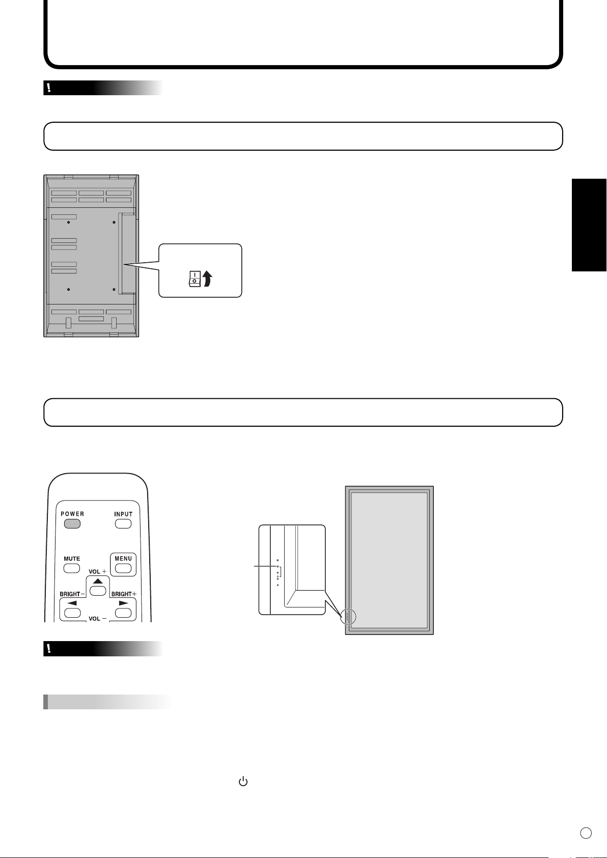
Ein- und ausschalten
Vorsicht
• Schalten Sie zuerst den Monitor und erst danach den PC oder ein anderes Wiedergabegerät ein.
Einschalten des Netzstroms
Hauptnetzschalter
DEUTSCH
Wenn der Hauptnetzschalter ausgeschaltet ist, kann der Monitor über den Netzschalter (POWER) an der
Fernbedienung nicht eingeschaltet werden.
Ein- und ausschalten
Drücken Sie auf die POWER-Taste, um den Monitor ein- bzw. auszuschalten.
Monitor eingeschaltet : Die Betriebs-LED leuchtet grün.
Monitor ausgeschaltet : Die Betriebs-LED leuchtet orange. (Standby-Modus)
Betriebs-LED
INPUT
Vorsicht
• Warten Sie zwischen dem Ein- und Ausschalten des Hauptnetzschalters oder der POWER-Taste immer
mindestens 5 Sekunden. Zu schnelles Ein- und Ausschalten kann zu einer Fehlfunktion führen.
TIPPS
• Wenn der Eingangsmodus (siehe Seite 20) auf “DIGITAL” oder “ANALOG” eingestellt ist und kein
Videoeingangssignal anliegt, schaltet sich die Hintergrundbeleuchtung des Monitors aus, und der Monitor
wechselt in den Wartemodus. (Die Betriebs-LED blinkt grün.) Wenn Sie in diesem Modus die POWER-Taste auf
der Fernbedienung drücken, wechselt der Monitor in den Standby-Modus.
• Wenn die Fernbedienung nicht verfügbar ist, können Sie den Monitor ein- oder ausschalten, indem Sie mit einem
spitzen Gegenstand auf den Netzschalter am Monitor drücken.
19
D
Page 74

20
D
Allgemeiner Betrieb
VOLUME 15
BRIGHT 15
Die Bedienung des Monitors erfolgt im Allgemeinen über die Fernbedienung.
INPUT (Eingangsmodus-Auswahl)
Das Auswahlmenü für den Eingangsmodus wird angezeigt.
Drücken Sie auf oder , um den Eingangsanschluss auszuwählen,
und drücken Sie auf , um den Anschluss zu ändern.
* Wenn die Fernbedienung nicht verfügbar ist, können Sie den
Eingangsanschluss wählen, indem Sie mit einem spitzen Gegenstand
auf den Eingangsschalter am Monitor drücken. (Siehe Seite 8.)
Audio
DIGITAL
ANALOG
COMPONENT
VIDEO
Video
Digitaler PC-RGB-Eingangsanschluss
Analoger PC-RGB-Eingangsanschluss
Component-Videoeingangsanschluss
Composite-Videoeingangsanschluss
PC-AudioEingangsanschluss
Audioeingangsanschlüsse
MUTE
Schaltet den Ton vorübergehend aus.
Drücken Sie erneut auf die MUTE-Taste, um den Ton in der zuvor
eingestellten Lautstärke wieder einzuschalten.
MENU
Mit dieser Taste können Sie das Bildschirm-Menü ein- und ausblenden
(siehe Seite 23).
VOL +/- (Lautstärke)
Wenn Sie auf oder drücken, wird das VOLUME-Menü
eingeblendet, sofern nicht gerade das Bildschirm-Menü angezeigt wird.
Drücken Sie auf , um die Lautstärke zu erhöhen, bzw. auf , um
die Lautstärke zu verringern.
* Wenn Sie etwa 4 Sekunden lang auf keine Taste drücken, verschwindet
das VOLUME-Menü automatisch.
BRIGHT +/- (Einstellung der Hintergrundbeleuchtung)
Wenn Sie auf oder drücken, wird das BRIGHT-Menü
eingeblendet, sofern nicht gerade das Bildschirm-Menü angezeigt wird.
Drücken Sie auf , um die Bildschirmhelligkeit zu erhöhen, bzw. auf
, um die Helligkeit zu verringern.
* Wenn Sie etwa 4 Sekunden lang auf keine Taste drücken, verschwindet
das BRIGHT-Menü automatisch.
SIZE (Auswahl der Bildschirmgröße)
Mit jedem Drücken dieser Taste wird die Bildschirmgröße in der folgenden
Reihenfolge weitergeschaltet (siehe Seite 21 und 22):
• WIDE <PANORAMA> → ZOOM 1 → ZOOM 2 → NORMAL → DotbyDot
<Punkt für Punkt> → WIDE...
Page 75

21
D
DEUTSCH
Allgemeiner Betrieb
MODE (Auswahl des Bildschirmmodus)
Mit jedem Drücken dieser Taste wird in der folgenden Reihenfolge auf den
nächsten Bildschirmmodus umgeschaltet:
•
STD (Normal)→ OFFICE*1 <BÜRO>→ VIVID <LEBHAFT>
*1 Die Display-Helligkeit wird verringert. (Dieser Modus spart Energie.)
*2 Wenn DIGITAL/ANALOG als Eingangsmodus ausgewählt wurde.
sRGB ist ein internationaler Standard der IEC (International Electrotechnical
Commission) für die Farbdarstellung.
Bei der Farbkonvertierung werden die Eigenschaften der Flüssigkristalle
genutzt, um eine möglichst originalgetreue Farbtonwiedergabe zu ermöglichen.
DISPLAY
Mit dieser Taste können Monitorinformationen am Bildschirm angezeigt
werden. Die Anzeige verschwindet automatisch nach etwa 15 Sekunden oder
nach dem neuerlichen Drücken dieser Taste.
INFORMATION ANALOG
→ sRGB *2→
STD...
INPUT MODE
SIZE
MODE
BRIGHT
VOLUME
OFF TIMER
ID No.
MODEL
S/N
1920x1080
ANALOG
:
WIDE
:
OFFICE
:
23
:
15
:
10:38
:
18
:
PN-655RE
:
XXXXXXXXX
:
V: 60 Hz H: 66.3 kHz
Umschalten der Bildschirmgröße
Umschalten der Bildschirmgröße (im Eingangsmodus DIGITAL/ANALOG)
Je nach anliegendem Eingangssignal kann die Anzeige am Monitor unverändert bleiben, selbst wenn
Sie die Bildschirmgröße ändern.
WIDE <PANORAMA> ZOOM 1 ZOOM 2
Passt das Bild so an, dass der
gesamte Bildschirm ausgefüllt
wird.
NORMAL
Das Bild füllt den gesamten
Bildschirm aus, ohne dass dabei
das Bildformat der
Eingangssignale verändert wird.
Ein Bild mit dem Bildformat 4:3 wird so vergrößert,
dass es die gesamte Bildschirmfläche ausfüllt, ohne
dass dabei das Bildformat geändert wird. Die
Bildkanten können dabei abgeschnitten werden.
DotbyDot <Punkt für Punkt>
Verwenden Sie diese Größe,
wenn die Untertitel im Modus
ZOOM 1 abgeschnitten werden.
* Bei einem Monitor mit einer
Bildschirmaufl ösung von 1600
x 1200 wird bei Auswahl der
Zeigt die Punkte der Signale vom
angeschlossenen PC entsprechend den
Punkten am Bildschirm an. *
Option “DotbyDot” <Punkt für
Punkt> der NORMAL-Bildschirm
angezeigt.
Page 76

22
D
Allgemeiner Betrieb
Umschalten der Bildschirmgröße (Im Eingangsmodus COMPONENT/VIDEO)
Je nach anliegendem Eingangssignal kann die Anzeige am Monitor unverändert bleiben, selbst wenn
Sie die Bildschirmgröße ändern.
WIDE <PANORAMA> ZOOM 1 ZOOM 2
TIPPS
Ein Bild mit einem Bildformat von
4:3 wird so gedehnt, dass es die
gesamte Bildfläche ausfüllt.
NORMAL
Zeigt das gesamte Bild des
Bildformats 4:3 an, ohne das
Bildformat zu ändern.
Ein Bild mit dem Bildformat 4:3 wird so
vergrößert, dass es die gesamte
Bildschirmfläche ausfüllt, ohne dass dabei
das Bildformat geändert wird. Die Bildkanten
können dabei abgeschnitten werden.
DotbyDot <Punkt für Punkt>
Zeigt die Punkte der Eingangssignale
als korrespondierende Punkte am
Bildschirm an.*
Verwenden Sie diese Größe,
wenn die Untertitel im Modus
ZOOM 1 abgeschnitten werden.
* Wenn bei einer der unten angeführten Bedingungen die Option “DotbyDot” <Punkt für
Punkt> ausgewählt wird, kann die Bildqualität durch Einstellen des Wertes “SHARPNESS”
<SCHÄRFE> im Menü “VIDEO ADJUSTMENT” <VIDEO EINST> nicht verändert werden.
· Wenn VIDEO als Eingangsmodus gewählt wurde
· Wenn COMPONENT als Eingangsmodus gewählt wurde und Bilder mit 480i oder 480p
angezeigt werden
• Bitte beachten Sie: Wenn Sie die Funktionen dieses Monitors zur Änderung der Bildschirmgröße oder zur
gleichzeitigen Anzeige zweier Eingangssignale benutzen, um den Bildschirm für kommerzielle oder öffentliche
Veranstaltungen z.B. in Cafes oder Hotels zu verkleinern oder zu vergrößern, könnten Sie dadurch geschützte
Rechte des Herstellers verletzen.
• Wenn die Option “ENLARGE” <VERGRÖßERN> ausgewählt wurde, wird die Bildschirmgröße auf den
“WIDE”-Modus <PANORAMA> fi xiert.
• Wenn die gleichzeitige Anzeiger zweier Eingangssignale ausgewählt wurde, kann die Bildschirmgröße nicht
verändert werden.
• Wenn Sie die Funktion dieses Monitors zur Änderung der Bildschirmgröße benutzen, kann sich das
Erscheinungsbild des ursprünglichen Videos verändern, wenn Sie eine Bildschirmgröße mit einem anderen
Bildformat auswählen als jenem, im dem das ursprüngliche Bild aufgenommen wurde (z.B. TV-Sendung oder
Videoeingang von einem externen Gerät). Bitte beachten Sie diesen Punkt bei der Auswahl der Bildschirmgröße.
• Wenn ein normales, nicht verbreitertes Bild (4:3) mit der Bildschirmgrößenveränderungsfunktion dieses Monitors
als Vollbild angezeigt wird, können die Ecken des Bildes unsichtbar werden oder verzerrt dargestellt werden.
Wenn Sie dies nicht wünschen, müssen Sie die Bildschirmgröße auf “NORMAL” setzen.
• Beim Abspielen kommerzieller Software können Teile des Bildes (wie z.B. Untertitel) abgeschnitten werden.
Wählen Sie in diesem Fall die optimale Bildschirmgröße mit der Bildschirmgrößenveränderungsfunktion des
Monitors aus. Bei manchen Software-Programmen kann es an den Bildschirmrändern zu Bildrauschen oder
Verzerrungen kommen. Dies ist auf die Eigenschaften der Software zurückzuführen und stellt keine Fehlfunktion
dar.
• Abhängig von der ursprünglichen Bildgröße (z.B. CinemaScope-Größe) können schwarze Ränder an den
Bildschirmrändern sichtbar sein.
Page 77

23
D
DEUTSCH
Menüoptionen
MANUAL
CLOCK
PHASE
H-POS
V-POS
AUTO
RESET
127
77
134
113
1920x1080
ANALOGADJUSTMENT
V: 60 Hz H: 66.3 kHz
MANUAL
BLACK LEVEL
CONTRAST
AUTO
1920x1080
15
15
GAIN CONTROL ANALOG
V: 60 Hz H: 66.3 kHz
Direkt am Bildschirm können Menüs eingeblendet werden, in denen über die Fernbedienung Audio- und
Videoeinstellungen vorgenommen sowie verschiedene Funktionen eingestellt werden können. Nähere
Informationen dazu fi nden Sie auf den Seiten, auf denen dieses Thema im Detail beschrieben wird.
Anzeigen des Bildschirmmenüs
Taste MENU
• Dient zum Ein- und Ausblenden des Bildschirm-Menüs.
• Schaltet zwischen verschiedenen Menüs um.
Cursorsteuerung (AUF/AB/LINKS/RECHTS)
• / : Mit diesen Tasten können Sie eine bestimmte
Option am Bildschirm auswählen.
• / : Mit diesen Tasten können Sie die ausgewählte
Option einstellen.
Beispiel für die Menü-Bedienung: Einstellen der CONTRAST im Menü GAIN
CONTROL.
1.
Drücken Sie auf
2.
Drücken Sie auf
MENU
, um das Bildschirm-Menü aufzurufen.
MENU
, um das Menü GAIN CONTROL aufzurufen.
3.
Drücken Sie auf , um die Option OSD H-POSITION auszuwählen.
Page 78

24
D
Menüoptionen
MANUAL
BLACK LEVEL
CONTRAST
AUTO
1920x1080
15
25
GAIN CONTROL ANALOG
V: 60 Hz H: 66.3 kHz
MANUAL
BLACK LEVEL
CONTRAST
AUTO
1920x1080
15
15
GAIN CONTROL ANALOG
V: 60 Hz H: 66.3 kHz
4.
Drücken Sie auf (oder ), um die Einstellung zu verändern.
5.
Drücken Sie auf
MENU
, um das Bildschirmmenü zu schließen.
Das Bildschirm-Menü verschwindet nach etwa 15 Sekunden automatisch, wenn in dieser Zeit keine Taste
gedrückt wird.
TIPPS
• Das angezeigte Menü hängt vom ausgewählten Eingangsmodus ab.
Menü-Anzeige
Menübezeichnung
Zeigt den momentan
ausgewählten Eingangsmodus
Bezeichnung der
Einstelloptionen und
deren Status
an.
Die momentan ausgewählte
Option wird markiert
dargestellt.
Zeigt die Bildschirmaufl ösung,
die Vertikalfrequenz, die
Horizontalfrequenz sowie
die Art des aktuellen
Eingangssignals an.
Gelb : Aktuelle Einstellung
Blau : Wählbare Optionen
Grau : Nicht wählbare Optionen (z.B. Die Funktion wird vom aktuellen Eingangssignal nicht unterstützt)
Page 79

25
D
DEUTSCH
Referenzkarte für Menüoptionen
Menüoptionen
Menü Option
ADJUSTMENT
<EINST>
(Siehe Seite 26.)
GAIN CONTROL
<BILDEINSTELLUNG>
(Siehe Seite 26.)
COLOR CONTROL
<FARBKONTROLLE>
(Siehe Seite 26.)
VIDEO ADJUSTMENT
<VIDEO EINST>
(Siehe Seite 27.)
MODE SELECT 1
<MODUS WÄHLEN 1>
(Siehe Seite 27.)
MODE SELECT 2
<MODUS WÄHLEN 2>
(Siehe Seite 27.)
MODE SELECT 3
<MODUS WÄHLEN 3>
(Siehe Seite 28.)
Eingangsmodus
DIGITAL
MANUAL ― Ja ― ―
AUTO ― Ja ― ―
CLOCK <TAKT> ― Ja ― ―
PHASE ― Ja ― ―
H-POS ― Ja ― ―
V-POS ― Ja ― ―
RESET ― Ja ― ―
MANUAL ― Ja ― ―
AUTO ― Ja ― ―
BLACK LEVEL <SCHWARZWERT> Ja Ja ― ―
CONTRAST <KONTRAST> Ja Ja ― ―
WHITE BALANCE <WEISS-ABGLEICH> Ja Ja ― ―
THRU <DIREKT> Ja ― ― ―
PRESET <V-EINS> Ja Ja ― ―
R-CONTRAST
<R-KONTRAST>
USER <BENUTZE>
COPY TO USER <KOPIE zu BENUTZER> Ja Ja ― ―
GAMMA Ja Ja ― ―
CONTRAST <KONTRAST> ― ― Ja Ja
BLACK LEVEL <SCHWARZWERT> ― ― Ja Ja
TINT <FARBTÖNUNG> ― ― Ja Ja
COLORS <FARBE> ― ― Ja Ja
SHARPNESS <SCHÄRFE> ― ― Ja Ja
WHITE BALANCE <WEISS-ABGLEICH> ― ― Ja Ja
GAMMA ― ― Ja Ja
480 LINES ― Ja ― ―
768 LINES ― Ja ― ―
BEZEL <RAND> Ja Ja ― ―
ENLARGE <VERGRÖßERN> Ja Ja ― ―
ENLARGE-POS <VERGRÖßERN POS> Ja Ja ― ―
MULTI ZOOM
<BILDSCHIRM
ZOOM>
AUDIO <TON>
OFF TIMER <AUS-TIMER> Ja Ja Ja Ja
OSD H-POSITION Ja Ja Ja Ja
OSD V-POSITION Ja Ja Ja Ja
LANGUAGE <SPRACHAUSWAHL> Ja Ja Ja Ja
SCREEN MOTION <BILDSCHIRM-BEWEG> Ja Ja Ja Ja
MOTION TIME1 <BEWEGUNG ZEIT 1> Ja Ja Ja Ja
MOTION TIME2 <BEWEGUNG ZEIT 2> Ja Ja Ja Ja
POWER ON DELAY <STROM EIN VERZOG> Ja Ja Ja Ja
ID No. SET <ID-Nr.> Ja Ja Ja Ja
COLOR SYSTEM <FARBSYSTEM> Ja Ja Ja Ja
PIP MODES <PIP MODUS> Ja Ja Ja Ja
PIP SIZE Ja Ja Ja Ja
PIP H-POS Ja Ja Ja Ja
PIP V-POS Ja Ja Ja Ja
PIP BLEND <PIP MISCHUNG> Ja Ja Ja Ja
PIP SOURCE <PIP QUELLE> Ja Ja Ja Ja
SOUND CHANGE <TON QUELLE> Ja Ja Ja Ja
MAIN POS Ja Ja Ja Ja
PbyP2 POS Ja Ja Ja Ja
AUTO OFF Ja Ja Ja Ja
G-CONTRAST
<G-KONTRAST>
B-CONTRAST
<B-KONTRAST>
IMAGE ZOOM
<ZOOM>
H-POS Ja Ja ― ―
V-POS Ja Ja ― ―
TREBLE <HÖHEN> Ja Ja Ja Ja
BASS Ja Ja Ja Ja
BALANCE Ja Ja Ja Ja
Ja Ja ― ―
Ja Ja ― ―
Ja Ja ― ―
Ja Ja ― ―
ANALOG
COMPONENT
VIDEO
Page 80

26
D
Menüoptionen
Menüoptionen
Das jeweils angezeigte Menü hängt vom gewählten Eingangsmodus ab.
ADJUSTMENT <EINST> (ANALOG)
[MANUAL / AUTO]
Dient zur Einstellung von CLOCK, PHASE, H-POS
(horizontale Positionierung) und V-POS (vertikale
Positionierung). Bei Verwendung eines WindowsBetriebssystems können die Einstellvorlagen auf der im
Lieferumfang enthaltenen CD-ROM verwendet werden.
(Siehe Seite 31.)
MANUAL ·············Die Parameter CLOCK, PHASE, H-POS
und V-POS werden manuell eingestellt.
AUTO ··················Die Parameter CLOCK, PHASE,
H-POS und V-POS werden automatisch
eingestellt. Verwenden Sie die
automatische Einstellung, wenn Sie einen
PC zum ersten Mal über den analogen PCRGB-Eingangsanschluss mit dem Monitor
verbinden oder wenn Sie Einstellungen am
PC ändern. (Siehe Seite 31.)
[CLOCK] <TAKT>
Einstellung der Samplingfrequenz für Videosignale. Sollte
verändert werden, wenn Bildfl ackern in Form horizontaler
Streifen auftritt. Wenn Sie das Einstellungsmuster (siehe
Seite 31) verwenden, dann ändern Sie die Einstellungen so,
dass keine horizontalen Streifen mehr zu sehen sind.
[PHASE]
Einstellung der Samplingfrequenzphase für Videosignale.
Diese Einstellung sollte dann angepasst werden, wenn
kleine Zeichen mit geringem Kontrast erscheinen und/oder
ein Flackern an den Bildschirmecken auftritt. Wenn Sie das
Einstellungsmuster (siehe Seite 31) verwenden, dann ändern
Sie die Einstellungen so, dass keine vertikalen Streifen mehr
zu sehen sind.
Die Einstellungen unter PHASE dürfen erst erfolgen,
nachdem CLOCK korrekt eingestellt wurde.
[H-POS]
Stellt die horizontale Bildposition ein.
[V-POS]
Stellt die vertikale Bildposition ein.
[RESET]
Durch Drücken der Taste
EINST auf die Werkseinstellungen zurückgesetzt.
werden alle Werte im Menü
GAIN CONTROL <BILDEINSTELLUNG>
(DIGITAL/ANALOG)
[MANUAL / AUTO] (ANALOG)
Dient zur Einstellung von BLACK LEVEL und CONTRAST.
MANUAL ·············Die Parameter BLACK LEVEL und
CONTRAST können durch Überprüfung
des Einstellungsmusters manuell
eingestellt werden. (Siehe Seite 31.)
AUTO ··················Die Parameter BLACK LEVEL und
CONTRAST werden automatisch
eingestellt.
[BLACK LEVEL] <SCHWARZWERT>
Stellt die Gesamthelligkeit der Videosignale ein.
[CONTRAST] <KONTRAST>
Stellt die Bildhelligkeit ein.
COLOR CONTROL <FARBKONTROLLE>
(DIGITAL/ANALOG)
[WHITE BALANCE <WEISS-ABGLEICH>
(Farbtemperatur)]
THRU ··················
(direkt) (nur für DIGITAL)
PRESET ·············Ermöglicht die Auswahl aus vordefi nierten
<V-EINS> Einstellungen. (Lesen Sie bitte auch die
USER··················Ermöglicht die Einstellung von
<BENUTZE> R-CONTRAST (Rot-Kontrast),
G-CONTRAST (Grün-Kontrast) und
B-CONTRAST (Blau-Kontrast).
[R-CONTRAST] <R-KONTRAST>
Stellt die Rot-Komponente ein.
[G-CONTRAST] <G-KONTRAST>
Stellt die Grün-Komponente ein.
[B-CONTRAST] <B-KONTRAST>
Stellt die Blau-Komponente ein.
[COPY TO USER] <KOPIE zu BENUTZER>
SET ·····················Kopiert den PRESET-Wert in die USER-
[GAMMA]
Wählt einen Gamma-Wert aus.
Zeigt den aktuellen Eingangssignalpegel an.
Beschreibung der Farbtemperaturen der
Einstellwerte auf der Seite 29.)
Einstellung.
Page 81

27
D
DEUTSCH
VIDEO ADJUSTMENT <VIDEO EINST>
(COMPONENT/VIDEO)
[CONTRAST] <KONTRAST>
Stellt die hellen Bildbereiche ein.
[BLACK LEVEL] <SCHWARZWERT>
Stellt die Gesamthelligkeit der Videosignale ein.
[TINT] <FARBTÖNUNG>
Stellt den Farbton ein. Mit + verstärken Sie den Grünanteil,
mit - den Magentaanteil.
[COLORS] <FARBE>
Stellt die Farbintensität ein.
[SHARPNESS] <SCHÄRFE>
Stellt die Bildschärfe ein.
[WHITE BALANCE] <WEISS-ABGLEICH>
Ermöglicht die Auswahl aus vordefi nierten Einstellungen.
(Lesen Sie bitte auch die Beschreibung der
Farbtemperaturen der Einstellwerte auf der Seite 29.)
[GAMMA]
Wählt einen Gamma-Wert aus.
MODE SELECT 1 <MODUS
WÄHLEN 1>
[480 LINES] (ANALOG)
Manuelle Auswahl der Eingangsaufl ösung.
[768 LINES] (ANALOG)
Manuelle Auswahl der Eingangsaufl ösung.
[BEZEL] <RAND> (DIGITAL/ANALOG)
Dient zur Einstellung der Bildbreite des Displays, wenn die
Vergrößerungsfunktion verwendet wird.
[ENLARGE] <VERGRÖßERN> (DIGITAL/ANALOG)
Legt die Anzahl der Bildschirmteilungen für die Vergrößerung
fest. (Siehe Seite 30.)
[ENLARGE-POS] <VERGRÖßERN POS>
(DIGITAL/ANALOG)
Damit können Sie festlegen, welche Bildschirmteilung bei
Verwendung der Vergrößerungsfunktion angezeigt werden
soll. (Siehe Seite 30.)
[MULTI ZOOM] <BILDSCHIRM ZOOM>
(DIGITAL/ANALOG)
Dient zur Einstellung der Bildschirmvergrößerung.
Drücken Sie auf
IMAGE ZOOM ....Damit kann die Vergrößerungsskala
<ZOOM> eingestellt werden.
H-POS ················
V-POS ················Damit wird die vertikale Position eingestellt.
[AUDIO] <TON>
Stellt die Lautstärke des eingebauten Lautsprechers ein.
Drücken Sie auf
TREBLE ·············Stellt die Höhen ein.
<HÖHEN>
BASS ··················Stellt die Bässe ein.
BALANCE ···········Stellt die Balance (links/rechts) ein.
, um das nächste Menü anzuzeigen.
Damit wird die horizontale Position eingestellt.
, um das nächste Menü anzuzeigen.
Menüoptionen
MODE SELECT 2
<MODUS WÄHLEN 2>
[OFF TIMER] <AUS-TIMER>
Legt die Zeit bis zum automatischen Abschalten des
Monitors fest (Monitor wechselt dann in den StandbyModus). Die Zeit kann zwischen 0 und 23 Stunden liegen.
Mit dem Wert 0 wird die automatische Abschaltung
deaktiviert.
[OSD H-POSITION]
Damit wird die horizontale Position des Bildschirmmenüs
eingestellt.
[OSD V-POSITION]
Damit wird die vertikale Position des Bildschirmmenüs
eingestellt.
[LANGUAGE] <SPRACHAUSWAHL>
Legt die Menüsprache fest.
Drücken Sie auf
[SCREEN MOTION] <BILDSCHIRM-BEWEG>
[MOTION TIME 1] <BEWEGUNG ZEIT 1>
[MOTION TIME 2] <BEWEGUNG ZEIT 2>
Ist die Option SCREEN MOTION aktiviert, so bewegt sich
das Bild in vertikaler und horizontaler Richtung, um den
Restbildanteil möglichst gering zu halten.
Nachdem die in MOTION TIME 1 festgelegte Zeit
verstrichen ist, wird das Bild mit dem in MOTION TIME 2
festgelegten Intervall eine gewisse Zeit lang vertikal und
horizontal bewegt. Nach Ende der Bewegung und erneutem
Ablauf der in MOTION TIME 1 festgelegten Zeit wird
die SCREEN MOTION neuerlich aktiviert. Während der
Bildschirmbewegung könnten die Bildkanten ausgeblendet
werden.
[POWER ON DELAY] <STROM EIN VERZOG>
Die Bildschirmdarstellung nach dem Einschalten des
Monitors kann für eine gewisse Zeit verzögert werden. Die
mögliche Verzögerungsdauer von maximal 60 Sekunden
kann in Schritten von je einer Sekunde eingestellt werden.
Wenn diese Funktion aktiviert ist, leuchtet die Betriebs-LED
orange. Mit dem Wert 0 wird diese Funktion deaktiviert.
[ID No. SET] <ID-Nr.>
Damit wird verschiedenen Monitoren, die mittels RS-232CKabel hintereinandergeschaltet sind (siehe Seite 36), jeweils
eine eigene ID-Nummer zugewiesen.
Für die ID-Nummern kann der Zahlenbereich von 1 bis 255
verwendet werden. Durch die Einstellung “0” nimmt das
Gerät an, dass keine ID-Nummern zugewiesen sind.
[COLOR SYSTEM] <FARBSYSTEM>
Wälen Sie das Farbsystem des AV-Geräs aus, das mit dem
Composite-Videoeingangsanschluss verbunden ist. (AUTO /
PAL / PAL-60 / SECAM / NTSC3.58 / NTSC4.43)
Wenn Sie AUTO auswählen, wird das Farbsystem
automatisch an das vorhandene Eingangssignal angepasst.
, um das nächste Menü anzuzeigen.
Page 82

28
D
Menüoptionen
MODE SELECT 3
<MODUS WÄHLEN 3>
[PIP MODES] <PIP MODUS> (Siehe Seite 29)
Damit kann der Anzeigemodus festgelegt werden.
OFF ····················Zeigt nur ein Bildschirmfenster an.
PIP ······················ Zeigt ein Unterfenster und ein Hauptfenster
an.
PbyP ··················· Zeigt ein Hauptfenster und ein Unterfenster
an untereinander an.
PbyP2 ·················Zeigt ein Hauptfenster mit 1280 Pixels in
der Längsrichtung und ein Unterfenster
untereinander an.
[PIP SIZE]
Damit können Sie die Größe des Unterfensters im PIPModus festlegen.
[PIP H-POS]
Damit können Sie die horizontale Position des Unterfensters
im PIP-Modus festlegen.
[PIP V-POS]
Damit können Sie die vertikale Position des Unterfensters im
PIP-Modus festlegen.
[PIP BLEND] <PIP MISCHUNG>
Verwenden Sie diese Menüoption im PIP-Modus, um das
Unterfenster transparent darzustellen.
[PIP SOURCE] <PIP QUELLE>
Damit wird das Eingangssignal des Unterfensters im PIP,
PbyP oder PbyP2 Modus ausgewählt.
[SOUND CHANGE] <TON QUELLE>
Legt fest, welche Tonquelle im PIP-, PbyP oder PbyP2Modus ausgegeben wird.
Wenn das Hauptfenster durch die AUTO OFF-Funktion als
Vollbild angezeigt wird, ist der Ton des Hauptfensters hörbar,
auch wenn der Ton für das Unterfenster ausgewählt wurde.
[MAIN POS]
Legt die Position des Hauptfensters im PbyP- oder PbyP2Modus fest.
[PbyP2 POS]
Legt die Position des Unterfensters im PbyP2-Modus fest.
[AUTO OFF]
Legt die Anzeigeart fest, wenn im PIP-, PbyP- oder PbyP2Modus keine Signale für das Unterfenster anliegen.
AUTO ··················Zeigt das Hauptfenster als Vollbildschirm
an.
MANUAL ·············Zeigt ein Hauptfenster und ein schwarzes
Unterfenster an.
TIPPS
• Wenn die Option WHITE BALANCE <WEISSABGLEICH> auf THRU <DIREKT> gesetzt ist, können
die Optionen BLACK LEVEL <SCHWARZWERT>,
CONTRAST <KONTRAST> und GAMMA nicht
eingestellt werden.
• Wenn der MODE <MODUS> auf sRGB oder VIVID
<LEBHAFT> gesetzt wurde, kann die Option COLOR
CONTROL <FARBKONTROLLE> nicht eingestellt
werden. (DIGITAL/ANALOG)
• Wenn MODE <MODUS> auf VIVID <LEBHAFT>
gesetzt ist, können WHITE BALANCE <WEISSABGLEICH> und GAMMA nicht eingestellt werden.
(COMPONENT/VIDEO)
Page 83

29
D
DEUTSCH
PIP
Beispiel Beispiel Beispiel
PbyP PbyP2
Innerhalb eines
Hauptfensters wird ein
Unterfenster angezeigt.
Zeigt ein Hauptfenster mit
1280 Pixels in der
Längsrichtung und ein
Unterfenster untereinander an.
Ein Hauptfenster und ein
Unterfenster werden
untereinander angezeigt.*
Hauptfenster
Unter-
fenster
Haupt-
fenster
Unter-
fenster
Hauptfenster
Unter-
fenster
Menüoptionen
Beschreibung der Farbtemperaturen der Einstellwerte
Der folgende Abschnitt beschreibt die Farbtemperaturen der jeweiligen Einstellwerte für den
BALANCE <WEISS-ABGLEICH>
.
Ab Werk ist der Wert “13” eingestellt (ca. 9000 K).
Einstellwert
Farbtemperatur
(K)
Einstellwert
Farbtemperatur
(K)
Einstellwert
Farbtemperatur
(K)
15 ca. 10.000 10 ca. 7.500 5 ca. 5.000
14 ca. 9.500 9 ca. 7.000 4 ca. 4.500
13 ca. 9.000 8 ca. 6.500 3 ca. 4.000
12 ca. 8.500 7 ca. 6.000 2 ca. 3.500
11 ca. 8.000 6 ca. 5.500 1 ca. 3.000
WHITE
Gleichzeitige Anzeige zweier Bildschirmeingänge
Die Fenster des PC-Eingangssignals (ANALOG/DIGITAL) und des AV-Eingangssignals (VIDEO/
COMPONENT) können gleichzeitig am Bildschirm dargestellt werden.
Diese Funktion kann mittels “PIP MODES” im Menü MODE SELECT 3 aktiviert werden. (Siehe Seite 28.)
• Das momentan ausgewählte Eingangssignal wird im Hauptfenster angezeigt.
• Zwei gleiche Eingangssignale, wie z.B. zwei PC-Eingänge oder zwei AV-Eingänge, können nicht
gleichzeitig am Monitor dargestellt werden.
* Wenn im PbyP-Hauptfenster die Option “COMPONENT” ausgewählt ist und
das 1080i-Videosignal anliegt, kann die Bildqualität auch durch Einstellen des
“SHARPNESS <SCHÄRFE>”-Wertes im Menü VIDEO ADJUSTMENT <VIDEO
EINST> nicht verändert werden.
TIPPS
• Wenn Sie die Bilder vom Computer-Bildschirm oder Fernsehapparat bzw. Videorekorder für gewerbliche Zwecke
verwenden oder in der Öffentlichkeit vorführen, könnten Sie die Copyright-Rechte des Autors verletzen.
• Die Bildschirmgröße ist bei der gleichzeitigen Verwendung zweier Bildschirmeingänge dieselbe wie bei
Verwendung eines einzelnen Eingangs. Sofern der DotbyDot-Bildschirm nicht als PIP-Hauptfenster verwendet
wird, wird er in NORMAL <NORMALER> Größe angezeigt.
• Bei Verwendung zweier Bildschirmeingänge ist die Funktion SCREEN MOTION <BILDSCHIRM BEWEG>
deaktiviert.
• Bei Verwendung zweier Bildschirmeingänge kann die Bildschirmanzeige nicht vergrößert werden.
Page 84

30
D
0
1
2
3
4
5
6
7
8
0
1
2
4
5
6
8
9
10
3
711
12
13
14
15
Einrichtung mit 4 Monitoren
Einrichtung mit 16 Monitoren
0
1
3
2
Einrichtung mit 9 Monitoren
Menüoptionen
Vergrößern
4, 9 oder 16 Monitor können zu einem einzigen großen Bildschirm verbunden werden. Jeder Monitor
stellt dabei 1/4, 1/9 oder 1/16 des ursprünglichen Bildes dar.
TIPPS
• AV-Eingangssignale (COMPONENT/VIDEO) können nicht für die Vergrößerungsfunktion verwendet werden.
• Um 9 oder mehr Monitore über DIGITAL-Signale miteinander zu verbinden, muss ein Splitter für das Videosignal (im
Handel erhältlich) verwendet werden.
• Wird die Verbindung im ANALOG-Modus hergestellt, muss ein Splitter für das Videosignal (im Handel erhältlich)
verwendet werden.
• Bei Verwendung der Vergrößerungsfunktion wird die SCREEN MOTION-Funktion <BILDSCHIRM BEWEG>
deaktiviert.
Page 85

31
D
DEUTSCH
Menüoptionen
Einstellungen für die PC-Anzeige
Wenn Sie zum ersten Mal den analogen PC-RGB-Eingangsanschluss zur Darstellung eines PC-Signals
verwenden oder wenn Sie die Einstellungen im PC ändern, müssen Sie die automatische Einstellung im
Menü ADJUSTMENT durchführen. (Siehe Seite 26.)
Bevor Sie Einstellungen im Menü ADJUSTMENT oder im Menü GAIN CONTROL durchführen, sollten
Sie ein Bild anzeigen lassen, um den gesamten Monitorbildschirm aufzuhellen.
Wenn Sie einen Windows-PC verwenden, benutzen Sie bitte das Einstellungsmuster auf der
mitgelieferten CD-ROM.
In diesem Handbuch sind alle Windows-Begriffe auf Englisch angegeben.
Laden des Einstellungsmusters
1. Schließen Sie den Computer am Monitor an.
2. Legen Sie die mitgelieferte CD-ROM in das CD-ROM-Laufwerk des Computers.
3. Öffnen Sie die CD-ROM im [My Computer].
4. Doppelklicken Sie auf die Datei [Adj_uty.exe], um das Einstellungsprogramm zu starten.
Das Einstellungsmuster erscheint. Sie können nun den Bildschirm automatisch oder manuell
einstellen.
5. Drücken Sie nach Beendigung des Einstellungsvorgangs auf die Taste [Esc] (auf der
Computertastatur), um das Einstellungsprogramm zu beenden.
6. Nehmen Sie die CD-ROM aus dem CD-ROM-Laufwerk.
TIPPS
• Wenn die Darstellung am Computer auf 65.000 Farben eingestellt ist, können die Farbebenen im Farbmuster
anders erscheinen, oder Grautöne können farbig erscheinen. (Dies ist auf die Spezifi kationen des Eingangssignals
zurückzuführen und stellt keine Fehlfunktion dar.)
Automatische Einstellung
1. Wählen Sie als Eingangsmodus die Option “ANALOG” und lassen Sie das oben dargestellte
Einstellungsmuster anzeigen.
2. Drücken Sie auf
3. Drücken Sie auf und wählen Sie “AUTO” aus. Die automatische Einstellung ist in wenigen
Sekunden abgeschlossen.
4. Drücken Sie sechs Mal auf
MENU
und rufen Sie das Menü ADJUSTMENT auf.
MENU
, um das Bildschirmmenü zu schließen.
TIPPS
• Wenn der Bildschirm mit einem automatischen Einstellungsdurchgang nicht richtig eingestellt werden kann,
wiederholen Sie die automatische Einstellung zwei oder drei Mal. Führen Sie nötigenfalls eine manuelle
Einstellung durch.
Page 86

Initialisierung (Reset) / Funktionsbeschränkung
ALL RESET
ADJUSTMENT LOCK
OSD DISPLAY
LED
RS-232C
OFF
OFF
OFF
LOCKED
ALL RESET
1 2
ON
ON
UNLOCKED
FUNCTION 1
MENU
Sie können den Kontrast, die Bildqualität und andere Einstellungen auf die Werksvorgaben zurücksetzen.
Sie können festlegen, ob Betriebs-LEDs leuchten sollen, und Sie können unter anderem die Steuerung
über die RS-232C-Schnittstelle aktivieren (siehe Seite 33).
D
32
1.
Drücken Sie zuerst etwa 5 Sekunden lang
auf
SIZE
und dann in dieser Reihenfolge auf , ,
, und .
Das Menü FUNCTION 1 erscheint.
2.
Wählen Sie die gewünschten Optionen aus und stellen Sie diese ein.
[ALL RESET]
Setzt alle Monitoreinstellungen außer der POWER ON DELAY-Funktion <STROM EIN VERZOG> auf
die Werkseinstellungen zurück.
Sie nach der Initialisierung (Reset) den Hauptnetzschalter aus und wieder ein.
[ADJUSTMENT LOCK] <OSD GESPERRT>
Deaktiviert den Betrieb.
OFF <AUS> ······· Aktiviert den Betrieb.
1 ························ Deaktiviert den gesamten Betrieb außer der Ein-/Ausschaltfunktion und der Anzeige
von “FUNCTION 1” <FUNKTION 1>.
2 ························ Deaktiviert den gesamten Betrieb außer der Anzeige von “FUNCTION 1”
<FUNKTION 1>.
[OSD DISPLAY] <OSD>
Damit können Menüs ein- bzw. ausgeblendet werden. Das Menü FUNCTION 1 <FUNKTION 1> kann
nicht ausgeblendet werden.
OFF <AUS> ······· Die Menüs werden nicht angezeigt.
ON <EIN> ·········· Die Menüs werden angezeigt.
[LED]
Legt fest, ob die Betriebs-LEDs leuchten sollen oder nicht.
OFF <AUS> ······· Betriebs-LEDs leuchten nicht.
ON <EIN> ·········· Betriebs-LEDs leuchten.
[RS-232C]
Legt fest, ob eine Fernsteuerung über den RS-232C-Anschluss erlaubt ist oder nicht (siehe Seite 33).
LOCKED <GESPERRT> ························ Deaktiviert die Fernsteuerung über den RS-232C-Anschluss.
UNLOCKED <NICHT GESPERRT> ······· Aktiviert die Fernsteuerung über den RS-232C-Anschluss.
3.
Drücken Sie auf
, um zum normalen Bildschirm zurückzukehren.
Page 87

Steuerung des Monitors über einen PC
Ungekreuztes RS-232C-Kabe
(im Handel erhältlich)
Zu COM-Port
Zum
RS-232CEingangsanschluss
▼ PC
RS-232CEingangsanschluss
Dieser Monitor kann über die RS-232C-Schnittstelle (COM-Port) von einem PC aus gesteuert werden.
Mit Hilfe eines PCs können Sie auch mehrere Monitore in Serie miteinander verbinden. Indem Sie
jedem Monitor eine eigene ID-Nummer zuweisen (siehe Seite 36), können Sie für jeden Monitor den
Eingangsmodus bzw. die Einstellungen separat festlegen oder den Status eines bestimmten Monitors
überprüfen.
PC-Anschluss
1:1-Verbindung mit einem PC......
Schließen Sie ein ungekreuztes RS-232C-Kabel zwischen dem COM-Port am PC (RS-232C-Stecker)
und dem RS-232C-Eingangsanschluss des Monitors an.
Allgemeiner Betrieb
DEUTSCH
33
D
Page 88

34
D
Steuerung des Monitors über einen PC
Ungekreuztes RS-232C-Kabel (im Handel erhältlich)
▼ Erster Monitor ▼ Zweiter Monitor
▼ PC
Ungekreuztes RS-232C-Kabel
(im Handel erhältlich)
Zu COM-Port
RS-232CAusgangsanschluss
RS-232CEingangsanschluss
RS-232CEingangsanschluss
RS-232CAusgangsanschluss
Serielle Verbindung von einem einzelnen PC......
Erweiterter Betrieb
Schließen Sie ein ungekreuztes RS-232C-Kabel zwischen dem COM-Port am PC (RS-232C-Stecker)
und dem RS-232C-Eingangsanschluss des ersten Monitors an. Schließen Sie als nächstes ein
ungekreuztes RS-232C-Kabel am RS-232C-Ausgangsanschluss des ersten Monitors und am RS232C-Eingangsanschluss des zweiten Monitors an. Verbinden Sie in derselben Weise einen dritten
Monitor und eventuelle weitere Monitore. Es können bis zu 20 Monitore miteinander verbunden
werden. (Die Anzahl der Monitore hängt von der Kabellänge und den Umgebungsbedingungen ab.)
Kommunikationseinstellungen
Stellen Sie die RS-232C-Kommunikationseinstellungen am PC so ein, dass sie den Kommunikationseinstellungen des Monitors entsprechen:
Baudrate 9600 bps Stopp-Bit 1 Bit
Datenlänge 8 Bit Flusskontrolle Keines
Paritätsbit Keines
Page 89

35
D
DEUTSCH
Steuerung des Monitors über einen PC
Kommunikation
Allgemeiner Betrieb
<Befehlsformat>
Wenn ein Befehl vom PC zum Monitor gesendet wird, führt der Monitor den empfangenen Befehl aus
und sendet eine entsprechende Antwortmeldung zurück an den PC.
Antwortcode
C1 C2 C3 C4 P1 P2 P3 P4
Befehlsfeld
(4 vorgeschriebene
alphanumerische
Zeichen)
Beispiel: VOLM0030
VOLM 30 (“ ” steht für ein Leerzeichen.)
* Achten Sie darauf, 4 Zeichen für den Parameter einzugeben. Füllen Sie den Befehl nötigenfalls mit
Leerzeichen auf.
Falsch: VOLM30
Richtig: VOLM 30 (“ ” steht für ein Leerzeichen. “ ” ist der Antwortcode (0DH, 0AH oder
0DH).)
Parameterfeld
(String aus 4 Zeichen,
bestehend aus: 0-9,
+, -, Leerzeichen, ?)
Legen Sie bei der Eingabe eines negativen Wertes einen dreistelligen numerischen Wert fest.
Beispiel: AUTR-009
Wenn Sie den sechsstelligen Befehl (MPOS) verwenden möchten, so benutzen Sie dazu einen
sechsstelligen numerischen Wert ohne Leerzeichen.
Beispiel: MPOS010097
Wenn ein Befehl den Buchstaben “R” für “Richtung” in der “RS-232C Befehlstabelle” auf Seite 42 enthält,
kann der Istwert mit einem “?” als Parameter zurückgegeben werden.
Beispiel: 1. Wenn keine ID-Nummer zugewiesen wurde:
VOLM???? ← Vom PC zum Monitor (Wie hoch ist die aktuelle Lautstärkeeinstellung?)
30 ← Vom Monitor zum PC (Aktuelle Lautstärkeeinstellung: 30)
2. Wenn eine ID-Nummer zugewiesen wurde (z.B. die ID-Nummer = 1)
VOLM ? ← Vom PC zum Monitor (“ ” steht für ein Leerzeichen.)
30 001 ← Vom Monitor zum PC (“ ” steht für ein Leerzeichen.)
<Antwortcodeformat>
Wenn ein Befehl korrekt ausgeführt wurde
Antwortcode
H, 0AH)
OK
(0D
Wenn ein Befehl nicht korrekt ausgeführt wurde*
Antwortcode
RRE
(0DH, 0AH)
Wenn die Befehlsausführung längere Zeit dauert
Antwortcode (0DH, 0AH)
IWTA
Wenn RS-232C gesperrt ist
Antwortcode (0DH, 0AH)
ECDKOL
Wird zurückgegeben, wenn die Ausführung des Befehls
abgeschlossen ist.
* Wird zurückgegeben, wenn kein derartiger Befehl vorliegt, oder
wenn der Befehl im aktuellen Monitorzustand nicht verwendet
werden kann.
* Wenn keine Kommunikation hergestellt wurde (z.B. wegen einer
schlechten Verbindung zwischen PC und Monitor), wird keine
Antwort zurückgemeldet (nicht einmal ERR).
Bei manchen Befehlen wird die Meldung “WAIT” als Antwort
angezeigt. Warten Sie in diesem Fall einen Moment, bis OK oder
ERR gemeldet wird. Während dieser Zeit können keine neuen
Befehle empfangen werden, selbst wenn sie gesendet wurden.
Wenn die RS-232C-Steuerung durch die Bediensperre gesperrt
wurde (siehe Seite 32), wird LOCKED als Antwort zurückgemeldet.
Page 90

36
D
Steuerung des Monitors über einen PC
Erweiterter Betrieb
Dieser Abschnitt beschreibt Befehle, die für hintereinander geschaltete Monitore gelten. Der allgemeine
Kommunikationsablauf ist identisch mit dem Abschnitt “Allgemeiner Betrieb”.
<ID-Nummern>
Sie können jedem Monitor eine eigene ID-Nummer zuweisen (siehe Seite 27). Dadurch können Sie
jeden Monitor in der Kette separat ansteuern.
Die Zuweisung der ID-Nummern können Sie entweder über das Bildschirmmenü (mit der Fernbedienung)
oder über den PC mit Hilfe des RS-232C-Kabels vornehmen.
[Beispiel]
ID-Nummer: 1 ID-Nummer: 2 ID-Nummer: 3 ID-Nummer: 4
PC
Wenn Monitore wie oben dargestellt miteinander verbunden sind, können Sie Befehle wie “Stelle die
Lautstärke des Monitors mit der ID 4 auf 20” ausführen.
Bei der Steuerung von hintereinander geschalteten Monitoren mit zugewiesenen ID-Nummern sollten
Sie die doppelte Vergabe einer ID-Nummer generell vermeiden.
Die ID-Nummern müssen nicht in aufsteigender Reihenfolge vom PC weg zugewiesen werden. Sie
können auch wie unten gezeigt zugewiesen werden.
[Beispiel]
ID-Nummer: 3 ID-Nummer: 2 ID-Nummer: 4 ID-Nummer: 1
PC
Page 91

37
D
DEUTSCH
ID-Nummer: 1 ID-Nummer: 2 ID-Nummer: 3 ID-Nummer: 4
PC
Steuerung des Monitors über einen PC
<Befehle für die ID-Steuerung>
Bei den auf dieser Seite gezeigten Befehlsbeispielen wird von folgender Verbindung und folgenden
zugewiesenen ID-Nummern ausgegangen.
ID-Nummer: 1 ID-Nummer: 2 ID-Nummer: 3 ID-Nummer: 4
PC
IDST......Ein Monitor, der diesen Befehl empfängt, setzt seine eigene ID-Nummer in das Parameterfeld.
Beispiel: IDST0001
OK
TIPPS
001 ← Die ID-Nummer dieses Monitors wird auf 1 gesetzt.
Mit dem IDST-Befehl können Sie mittels Wiederholungssteuerung allen Monitoren automatisch eine IDNummer zuweisen (siehe “Wiederholungssteuerung” auf Seite 39).
Mit dem Befehl “IDST001+” werden zum Beispiel automatisch die ID-Nummern wie unten dargestellt
zugewiesen.
[Beispiel]
IDST001+ ← Befehl zur ID-Einstellung mit Wiederholungssteuerung
WAIT
OK
OK 002 ← Antwort “OK” von der ID-Nummer: 2
OK 003 ← Antwort “OK” von der ID-Nummer: 3
OK 004 ← Antwort “OK” von der ID-Nummer: 4 (Ende)
001 ← Antwort “OK” von der ID-Nummer: 1
Page 92

38
D
Steuerung des Monitors über einen PC
IDSL .......Der Parameter dieses Befehls weist dem Monitor die ID-Nummer zu.
Der Monitor muss den nächsten Befehl ausführen.
Beispiel:
IDSL0002 ← Der nächste Befehl gilt für den Monitor mit der ID-Nummer 2.
WAIT ← Suche nach dem Monitor mit der ID-Nummer 2
OK
VOLM0030 ← Einstellen der Lautstärke des Monitors mit der ID-Nummer 2 auf 30.
WAIT ← Verarbeitung
OK
VOLM0020 ← Lautstärke wird auf 20 eingestellt.
OK
(der mit dem PC direkt verbunden ist) wird auf 20
IDLK .......Der Parameter dieses Befehls weist dem Monitor die ID-Nummer zu.
Der Monitor muss alle weiteren Befehle ausführen.
Beispiel:
IDLK0002 ← Die folgenden Befehle gelten für den Monitor mit der ID-Nummer 2.
WAIT ← Suche nach dem Monitor mit der ID-Nummer 2
OK
VOLM0030 ← Einstellen der Lautstärke des Monitors mit der
WAIT ← Verarbeitung
OK
VOLM0020 ← Einstellen der Lautstärke des Monitors mit der
WAIT
OK
IDLK0000 ← Abbrechen der Zuweisung einer festen ID-Nummer
WAIT ← Abbrechen von IDLK
OK
VOLM0010
OK
002 ← Gefunden wurde der Monitor mit der ID-Nummer 2
002 ← Antwort “OK” vom Monitor mit der ID-Nummer 2
001 ← Die Lautstärke des Monitors mit der ID-Nummer 1
eingestellt.
002 ← Gefunden wurde der Monitor mit der ID-Nummer 2
ID-Nummer 2 auf 30.
002
ID-Nummer 2 auf 20.
002
002 ← Abbrechen komplett
001 ← Die Lautstärke des Monitors mit der ID-Nummer 1
(der mit dem PC direkt verbunden ist) wird auf 10 eingestellt. (IDLK wird abgebrochen.)
Der IDSL-Befehl ist nur
einmalig wirksam, und
zwar für den unmittelbar
darauffolgenden Befehl.
Der IDLK-Befehl bleibt bis zum
Abbruch oder Ausschalten des
Monitors wirksam.
Beispiel:
IDCK ...... Zeigt die momentan einem Monitor zugewiesene ID-Nummer am Bildschirm an, sowie die
momentan für IDLK eingestellte ID-Nummer (sofern vorhanden).
(Nach Ausführung von IDLK0002)
IDCK0000 ← (Der Parameter ist bedeutungslos.)
ID:001 IDLK:002 ← Zurückgegebene Antwort.
Die ID-Nummer wird ebenfalls am Monitor angezeigt.
IDCK000+ ← Wiederholungssteuerung
WAIT
ID:001 IDLK:000
(Wenn ein Befehl mit der Wiederholungssteuerung verwendet wird, wird die
ID-Zuweisung mit IDSL oder IDLK abgebrochen.)
ID:002 IDLK:000
ID:003 IDLK:000
ID:004 IDLK:000
Page 93

39
D
DEUTSCH
Steuerung des Monitors über einen PC
<Wiederholungssteuerung>
Dieses System verfügt über eine Funktion, mit der mehrere hintereinander geschaltete Monitore
über einen einzigen Befehl eingestellt werden können. Diese Funktion bezeichnet man als
Wiederholungssteuerung.
Die Wiederholungssteuerung kann auch ohne Zuweisung von ID-Nummern verwendet werden.
[Beispiel]
Setze 1 Setze 2 Setze 3 Setze 4
PC
Wenn Monitore wie oben gezeigt miteinander verbunden sind, können Sie einen Befehl wie z.B. “Die
Eingangseinstellungen aller Monitore auf DVI: DIGITAL setzen” ausführen.
<Wiederholungssteuerungsbefehl>
Für die Wiederholungssteuerung muss das VIERTE ZEICHEN des Parameters auf “+” gesetzt werden.
Beispiel:
VOLM030+ ← Stellt die Lautstärke aller Monitore auf 30 ein.
Bei der Wiederholungssteuerung senden alle angeschlossenen Monitore eine Antwort zurück.
Wenn Sie überprüfen möchten, ob ein Wert von einem bestimmten Gerät zurückgesendet wurde,
müssen Sie zuvor jedem Monitor eine eigene ID-Nummer zuweisen.
Wenn einige Monitor keine Antwort senden, liegt dies wahrscheinlich daran, dass diese Monitore
den Befehl nicht erhalten oder den Befehl noch nicht abgearbeitet haben. Senden Sie keinen neuen
Befehl.
Beispiel:
(Wenn 4 Monitore miteinander verbunden sind, denen die ID-Nummern 1 bis 4 zugewiesen wurden)
VOLM030+
WAIT
OK
OK
OK
OK
Die Wiederholungssteuerung kann auch zum Auslesen der Einstellungen verwendet werden.
Beispiel:
001
002
003
004 ← Wenn 4 Monitore hintereinander angeschlossen sind, kann ein zuverlässiger Betrieb
nur sichergestellt werden, indem ein neuer Befehl nur nach Einlangen einer Antwort
vom 4. (letzten) Monitor gesendet wird.
VOLM???+
WAIT
10
20
30
30
TIPPS
• Wird die Wiederholungssteuerung während der ID-Zuweisung (IDSL, IDLK) verwendet, so wird die ID-Zuweisung
abgebrochen.
001
002
003
004
Die Lautstärkeeinstellungen aller Monitore werden zurückgesendet.
Page 94

40
D
Steuerung des Monitors über einen PC
<Antwortformat im erweiterten Betrieb
Wenn ein Befehl korrekt ausgeführt wurde
• Antwort, wenn keine ID-Nummer zugewiesen wurde
Antwortcode
OK
• Antwort, wenn eine ID-Nummer zugewiesen wurde
O K SPC 0 0 1
ID-Nummer des entsprechenden Monitors
Wenn ein Befehl nicht korrekt ausgeführt wurde*
• Antwort, wenn keine ID-Nummer zugewiesen wurde
RRE
• Antwort, wenn eine ID-Nummer zugewiesen wurde
RRE SPC 0 0 1
(0DH, 0AH)
Leerzeichen (20H)
Antwortcode
(0DH, 0AH)
Leerzeichen (20H)
Antwortcode
H, 0AH)
(0D
Antwortcode
(0D
H, 0AH)
>
Eine Antwort wird zurückgegeben, wenn
die Ausführung des passenden Befehls
abgeschlossen ist.
ID-Nummer
* Wird zurückgegeben, wenn kein derartiger Befehl vorliegt, oder wenn der Befehl im aktuellen Monitorzustand
nicht verwendet werden kann.
* Wenn keine Kommunikation hergestellt wurde (z.B. wegen einer schlechten Verbindung zwischen PC und
Monitor), wird keine Antwort zurückgemeldet (nicht einmal ERR).
* Wenn die angegebene ID-Nummer keinem Monitor zugewiesen wurde (z.B. wenn der Befehl IDSL0002
verwendet wird, aber kein Monitor mit der ID-Nummer 2 vorhanden ist), wird keine Antwort zurückgemeldet.
Page 95

41
D
DEUTSCH
Steuerung des Monitors über einen PC
Wenn die Befehlsausführung längere Zeit dauert
Antwortcode (0DH, 0AH)
IWTA
Bei den folgenden Befehlen wird “WAIT” als Antwort zurückgegeben. In diesem Fall wird ein Wert
zurückgemeldet, wenn Sie eine Zeitlang warten. Senden Sie während dieser Zeit keinen Befehl.
An den WAIT-Befehl ist keine ID-Nummer angehängt.
• Befehle, bei denen WAIT als Antwort zurückgegeben wird:
- Bei Verwendung der Wiederholungssteuerung
- Bei Verwendung eines IDSL- oder IDLK-Befehls
- Bei Verwendung eines der folgenden Befehle: RSET, INPS, ASNC, WIDE, EMAG, EPOS, PXSL,
POWR, AGIN, MWIN, MWIP, MWPP
Wenn die Steuerung über RS-232C durch die Bediensperre gesperrt wurde. (Siehe Seite 32.)
Antwortcode
ECDKOL
Wenn der aktuelle Parameter mit “?” für den Parameter ausgelesen wird (für numerische Werte
usw.)
• Antwort, wenn keine ID-Nummer zugewiesen wurde
Beispiel:
VOLM????
10
• Antwort, wenn eine ID-Nummer zugewiesen wurde (im untenstehenden Beispiel: ID-Nummer = 1)
Beispiel:
VOLM????
10 001
(0DH, 0AH)
<Kommunikationsintervall>
• Nachdem die Meldung OK oder ERR angezeigt wurde, müssen Sie die nächsten Befehle senden.
Legen Sie mindestens 10 Sekunden als Wartezeit für die Antwort auf einen Befehl fest.
• Legen Sie ein Intervall von 100 ms oder mehr zwischen der Befehlsantwort und der Übertragung des
nächsten Befehls fest.
VOLM0020
OK
Intervall von 100 ms oder mehr
INPS0001
WAIT
OK
Page 96

42
D
Steuerung des Monitors über einen PC
RS-232C Befehlstabelle
<Informationen zur Befehlstabelle>
Befehl: Befehlsfeld (Siehe Seite 35.)
Richtung: W Wenn der “Parameter” im Parameterfeld (siehe Seite 35) festgelegt ist,
funktioniert der Befehl wie unter “Steuerung/Antwortinhalt” beschrieben.
R Der unter “Antwort” angegebene zurückgemeldete Wert kann durch die
Einstellung “????”, “
Parameterfeld (siehe Seite 35) abgefragt werden.
Parameter: Parameterfeld (Siehe Seite 35.)
Antwort: Antwort (zurückgegebener Wert)
* “Ja” zeigt Befehle an, die im Standby-Modus verwendet werden können.
Leistungsregelung/Eingangsmodus-Auswahl
?” oder “???+” (Wiederholungssteuerung) im
Element Befehl
Leistungsregelung POWR W
Eingangsmodus-Auswahl INPS W
Richtung
Parameter
Antwort Steuerung/Antwortinhalt
0 Umschalten auf Standby-Modus.
1 Rückkehr aus dem Standby-Modus.
R
R
0 Standby-Modus
1 Normal-Modus
2 Warten auf Eingangssignal
0 Umschalten des Eingangsmodus
1 Digitaler PC-RGB (DVI) (DIGITAL)
2 Analoger PC-RGB (ANALOG)
3 Component (COMPONENT)
4 VIDEO
1 Digitaler PC-RGB (DVI) (DIGITAL)
2 Analoger PC-RGB (ANALOG)
3 Component (COMPONENT)
4 VIDEO
*
Ja
Ja
Page 97

43
D
DEUTSCH
Bildeinstellung (DIGITAL)
Steuerung des Monitors über einen PC
Element Befehl
WHITE BALANCE
<WEISS-ABGLEICH>
GAMMA GAMM WR 0 - 2 0 - 2 0:1.8, 1:2.2, 2:2.4 Ja
GAIN CONTROL
<BILDEINSTELLUNG>
EINGANGSAUFLÖSUNG
ENLARGE
<VERGRÖßERN>
Bildschirmformat WIDE WR
THRU <DIREKT>
PRESET <V-EINS> 1 - 15 1 - 15
USER <BENUTZE> 99 99
R-CONTRAST
<R-KONTRAST>
G-CONTRAST
<G-KONTRAST>
B-CONTRAST
<B-KONTRAST>
BLACK LEVEL
<SCHWARZWERT>
CONTRAST
<KONTRAST>
ÜBERPRÜFUNG DER
AUFLÖSUNG
VERGRÖSSERUNGSEINSTELLUNG
Randbreite
Bildposition (2 x 2) EPOS WR
Bildposition (3 x 3) EPOS WR
Bildposition (4 x 4) EPOS WR
Richtung
Parameter
Antwort Steuerung/Antwortinhalt
CTMP WR
CRTR WR 0 - 255 0 - 255
CRTG WR 0 - 255 0 - 255
CRTB WR 0 - 255 0 - 255
BLVL WR 0 - 60 0 - 60
CONT WR 0 - 60 0 - 60
PXCK R - Gibt die aktuelle Aufl ösung in der Form hhh, vvv zurück. Nein
EMAG WR
BEZH WR 0 - 100 0 - 100 Legt die Randbreite der kürzeren Seite fest.
BEZV WR 0 - 100 0 - 100 Legt die Randbreite der längeren Seite fest.
00
0 0 Vergrößerung aus
1 1 2 x 2
2 2 3 x 3
3 3 4 x 4
Nein
0 - 3 0 - 3 Siehe Seite 30.
0 - 8 0 - 8 Siehe Seite 30.
0 - 15 0 - 15 Siehe Seite 30.
1 1 WIDE <PANORAMA>
2 2 NORMAL
3 3 DotbyDot <Punkt für Punkt>
4 4 ZOOM1
5 5 ZOOM2
*
Ja
Ja
Ja
Page 98

44
D
Steuerung des Monitors über einen PC
Bildeinstellung (ANALOG)
Element Befehl
ADJUSTMENT
<EINST>
GAIN CONTROL
<BILDEINSTELLUNG>
WHITE BALANCE
<WEISS-ABGLEICH>
GAMMA GAMM WR 0 - 2 0 - 2 0:1.8, 1:2.2, 2:2.4 Ja
Aufl ösung
ENLARGE
<VERGRÖßERN>
Bildschirmformat WIDE WR
AUTO
CLOCK <TAKT> CLCK WR 0 - 255 0 - 255
PHASE PHSE WR 0 - 255 0 - 255
BILDPOSITION
RESET ARST W 1
AUTO AGIN W 1 Nein
BLACK LEVEL
<SCHWARZWERT>
CONTRAST
<KONTRAST>
PRESET <V-EINS>
USER <BENUTZE> 99 99
R-CONTRAST
<R-KONTRAST>
G-CONTRAST
<G-KONTRAST>
B-CONTRAST
<B-KONTRAST>
Prüfung PXCK R - Gibt die aktuelle Aufl ösung in der Form hhh, vvv zurück.
Pixeleinstellung PXSL WR
VERGRÖSSERUNGSEINSTELLUNG
Randbreite
Bildposition (2 x 2) EPOS WR
Bildposition (3 x 3) EPOS WR
Bildposition (4 x 4) EPOS WR
Richtung
Parameter
Antwort Steuerung/Antwortinhalt
ASNC W 1
HPOS WR 0 - 255 0 - 255 Stellt die Position in der längsten Richtung ein.
VPOS WR 0 - 255 0 - 255 Stellt die Position in der kürzesten Richtung ein.
BLVL WR 0 - 31 0 - 31
CONT WR 0 - 31 0 - 31
CTMP WR
CRTR WR 0 - 255 0 - 255
CRTG WR 0 - 255 0 - 255
CRTB WR 0 - 255 0 - 255
EMAG WR
BEZH WR 0 - 100 0 - 100 Legt die Randbreite der kürzeren Seite fest.
BEZV WR 0 - 100 0 - 100 Legt die Randbreite der längeren Seite fest.
1-15 1-15
0 0 V: 768) reserviert (ERR)
1 1 V: 768) 1360 x 768
2 2 V: 768) 1280 x 768
3 3 V: 768) 1024 x 768
4 4 V: 480) reserviert (ERR)
5 5 V: 480) 848 x 480
6 6 V: 480) 640 x 480
0 0 Vergrößerung aus
1 1 2 x 2
2 2 3 x 3
3 3 4 x 4
0 - 3 0 - 3 Siehe Seite 30.
0 - 8 0 - 8 Siehe Seite 30.
0 - 15 0 - 15 Siehe Seite 30.
1 1 WIDE <PANORAMA>
2 2 NORMAL
3 3 DotbyDot <Punkt für Punkt>
4 4 ZOOM1
5 5 ZOOM2
Nein
Nein
Nein
*
Ja
Ja
Ja
Page 99

45
D
DEUTSCH
Steuerung des Monitors über einen PC
Bildeinstellung (COMPONENT/VIDEO)
Element Befehl
VIDEO ADJUSTMENT
<VIDEO EINST>
GAMMA GAMM WR 0 - 2 0 - 2 0:1.8, 1:2.2, 2:2.4 Ja
Bildschirmformat WIDE WR
ÜBERPRÜFUNG DER AUFLÖSUNG RESO R
CONTRAST
<KONTRAST>
BLACK LEVEL
<SCHWARZWERT>
COLOR <FARBE> COLR WR 0 - 60 0 - 60
TINT
<FARBTÖNUNG>
SHARPNESS
<SCHÄRFE>
WHITE BALANCE
<WEISS-ABGLEICH>
Richtung
Parameter
Antwort Steuerung/Antwortinhalt
CONT WR 0 - 60 0 - 60
BLVL WR 0 - 60 0 - 60
TINT WR 0 - 60 0 - 60
SHRP WR 0 - 31 0 - 31
CTMP WR 1 - 15 1 - 15
1 1 WIDE <PANORAMA>
2 2 ZOOM1
3 3 ZOOM2
4 4 NORMAL
5 5 DotbyDot <Punkt für Punkt>
Aufl ösung
480i, 480p, 1080i, 720p, 576i, 576p Nein
Allgemeine Steuerung für alle Eingangsmodi
Element Befehl
PIP
PbyP
PbyP2
AUDIO <TON> TREBLE <HÖHEN> AUTR WR -10 - 10 -10 - 10
OFF TIMER <AUS-TIMER> OFTM WR 0 0 Timer aus
ID-Nummer Einstellung ID-Nr. IDST W 0 - 255 Weist dem Monitor eine ID-Nummer zu. (“0” steht für “keine ID-Nummer”.)
COLOR SYSTEM <FARBSYSTEM> CSYS WR 0 - 5 0 - 5 0: AUTO, 1: PAL, 2: PAL-60, 3: SECAM, 4: NTSC3,58, 5: NTSC4,43 Ja
Information Modell INF1 R Wert
Bildschirm-Modus BMOD WR 0 0 STD (Normal)
HELLIGKEIT VLMP WR 0 - 31 0 - 31 Helligkeit Ja
VOLUME <LAUTSTÄRKE> VOLM WR 0 - 31 0 - 31 Lautstärke Ja
PIP MODES
<PIP MODUS>
PIP SIZE MWSZ WR 0 0 SMALL <Klein>
UNTERFENSTER-POSITION
PIP V/H-POS MPOS WR
PIP BLEND
<PIP MISCHUNG>
PIP SOURCE
<PIP QUELLE>
SOUND CHANGE
<TON QUELLE>
MAIN POS
(Hauptfenster)
PbyP2 POS
(Unterfenster)
AUTO OFF MOFF WR 0 0 MANUAL
BALANCE AUBL WR -10 - 10 -10 - 10
Einstellung ID-Nr.
(einmal)
Einstellung ID-Nr.
(nachfolgende)
ID-Prüfung IDCK W 0
Serien-Nr. SRNO R Wert
Richtung
Parameter
Antwort Steuerung/Antwortinhalt
MWIN WR 0 0 OFF <AUS>
MHPS WR 0 - 100 0 - 100 Stellt die Position in der längsten Richtung ein.
MVPS WR 0 - 100 0 - 100 Stellt die Position in der kürzesten Richtung ein.
MWBL WR 0 - 15 0 - 15 Ja
MWIP WR 1 1 Digitaler PC-RGB (DVI)(DIGITAL)
MWAD WR 1 1 MAIN
MWPP WR 0 0 POS1
MW2P WR 0 0 POS3
OFTR R Wert Verbleibende Zeit
IDSL W
IDLK W
1 1 PIP
2 2 PbyP
3 3 PbyP2
2 2 LARGE <Groß>
0 - 100,
0 - 100,
0 - 100
2 2 Analoger PC-RGB (ANALOG)
3 3 Component (COMPONENT)
4 4 VIDEO
2 2 SUB
1 1 POS2
2 2 POS1
1 1 AUTO
R 0 - 255 Gibt die ID-Nummer des Monitors zurück.
1 - 255
0
1 - 255
1 1 OFFICE <BÜRO>-Modus
2 2 VIVID <LEBHAFT>-Modus
3 3 sRGB (im Eingangsmodus DIGITAL/ANALOG)
Legt die Position im MPOSxxxyyy-Format fest (xxx: längere Seite, yyy: kürzere
0 - 100
Seite). Die Antwort kommt in der Form (xxx, yyy).
Damit wird eine ID-Nummer für einen Monitor festgelegt. Diese ID-Nummer gilt nur für
den unmittelbar nach diesem Befehl folgenden Befehl.
Löscht die vorhandene ID-Nummer, falls bereits eine zugewiesen wurde.
Damit wird eine ID-Nummer für einen Monitor festgelegt. Diese ID-Nummer gilt für
den auf diesen Befehl folgenden Befehl und alle darauffolgenden Befehle.
Löscht die vorhandene ID-Nummer, falls bereits eine zugewiesen wurde.
ID: XXX
Zeigt die ausgewählte ID-Nummer und die eigene ID-Nummer des Monitors am
IDLK: YYY
Bildschirm an.
*
Ja
Ja
*
Ja
Ja1 1 MEDIUM <Mittel>
Ja
Ja
Ja
Ja
Ja
Ja1 1 POS2
Ja
JaBASS AUBS WR -10 - 10 -10 - 10
Nein1 - 23 1 - 23 Ausschalt-Timer
Ja
Ja
Ja0
Ja
Ja
Page 100

Steuerung des Monitors über einen PC
Element Befehl
Stummschaltung MUTE WR 0 0 OFF (aus)
ALL RESET RSET W 0 Alles zurücksetzen Nein
OSD DISPLAY <OSD> LOSD WR 0 0 OSD-Display ein
ADJUSTMENT LOCK <OSD GESPERRT> ALCK WR 0 - 2 0 - 2 0: OFF <AUS> Ja
LED OFLD WR 0 0 LED ON (ein)
SCREEN MOTION <BILDSCHIRM-BEWEG> SCSV WR 0 0 BILDSCHIRM-BEWEG AUS
MOTION TIME 1 <BEWEGUNG ZEIT 1> MTIM WR 0 - 20 0 - 20
MOTION TIME 2 <BEWEGUNG ZEIT 2> MINT WR 10 - 990 10 - 990 Die Zeit wird in 10-Sekunden-Schritten festgelegt.
Power On Delay <STROM EIN VERZOG> PWOD WR 0 0 Strom Ein Verzögerung AUS
LANGUAGE <SPRACHAUSWAHL> LANG WR 14 14 ENGLISH
TEMPERATURSENSOR DSTA R 0 Innentemperatur normal
Ursache für letzten Standby-Modus STCA W 0 Initialisierung
Richtung
Parameter
Antwort Steuerung/Antwortinhalt
1 1 ON (ein)
1 1 OSD-Display aus
1 1 LED OFF (aus)
1 1 BILDSCHIRM-BEWEG EIN
1 - 60 1 - 60 Strom Ein Verzögerung EIN
1 1 DEUTSCH
2 2 FRANÇAIS
3 3 ITALIANO
4 4 ESPAÑOL
5 5 РУССКИЙ
1 Innentemperatur abnormal (Standby-Modus)
Innentemperatur abnormal (Temperatur ist jetzt normal, war aber während des
2
Betriebs zu hoch.)
3 Innentemperatur abnormal (Die Helligkeit der Hintergrundbeleuchtung nimmt ab.)
4 Temperatursensor abnormal
R 0 Es ist kein erkennbarer Fehler aufgetreten
1 Durch Fernbedienung auf Standby-Modus geschaltet
2 Durch Netzschalter am Monitor auf Standby-Modus geschaltet
3 Durch RS-232C auf Standby-Modus geschaltet
4 Durch “Kein Signal/Zeitüberschreitung” auf Wartemodus geschaltet
(einschl: VESA DPMS/DMPM)
6 Durch zu hohe Temperatur auf Standby-Modus geschaltet
7 Durch OFF TIMER-Funktion auf Standby-Modus geschaltet
Nein
Ja
Ja
Ja
Ja
Ja
Ja
Ja
Ja
*
D
46
 Loading...