

Page 1
PERSONAL COPIER: SF-2014/2114/2214 Series
Date
:
Oct. 31, 1997
SF-2014/2114/2214 SERIES
CORRECTIVE ACTIONS AGAINST DAMAGE TO THE LOWER
FRAME DUE TO LOOSENESS OF THE TORSION BAR.
1.Model Name: SF-2014/2114/2214, SN-1420/1430, Z-800 (For north American)
2.General: This report describes the corrective actions against damage to the lower frame (the
No. : PCE-0012
frame is broken into shutters,in the worst case) which is caused by the Torsion bar on
the front end coming loose and hitting against the left side of the frame unit.
(This symptom occurred at machines manufactured in about September 1996.)
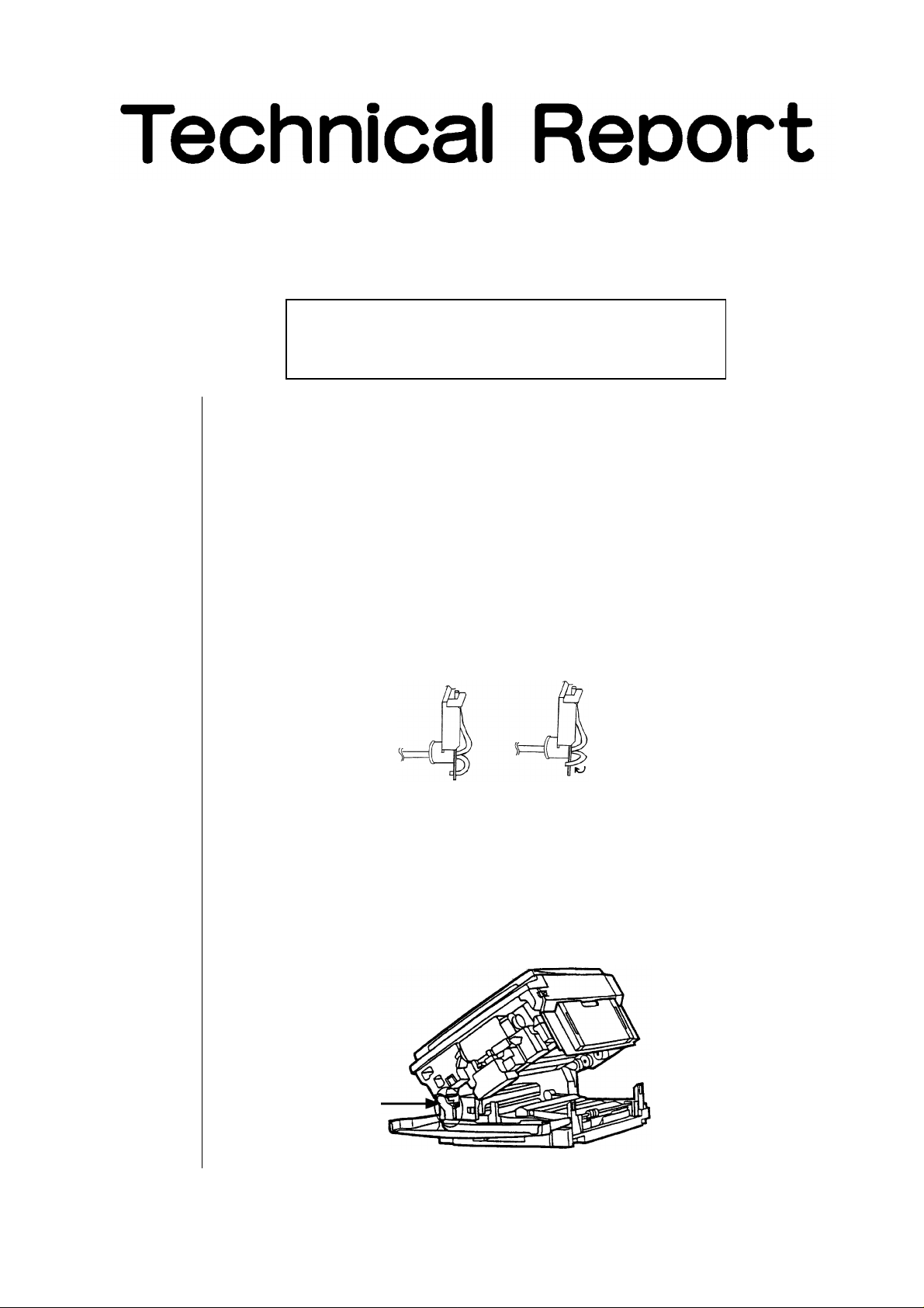
3.Description: We are in the process of investigation into the cause of this trouble. But it has been
confirmed that repeated open/close operation of the upper frame infrequently causes
the tip of the Torsion bar to come loose from the fixing plate, resulting in the Torsion bar
hitting against the left side of the lower frame and damage to the lower frame.
[Normal]
4.Action: A torsion bar fixing bracket is added.
[Torsion bar tip coming loose]
<Parts required>
Torsion bar fixing bracket … 1 pc (Fig.2-[2]) Speed nut … 1 pc (Fig.2-[4])
Screw (Cup tight M4 × 8) … 1 pc (Fig.2-[3]) Wire saddle … 1 pc (Fig.5-[1])
<Installation procedure>
1) Open the front cover. (See Fig.1)
2) Remove the mounting screw (1 piece) from the fusing unit connector cover and
remove the fusing unit cover. (See Fig.1)
Fusing unit cover
[Fig.1]
SHARP CORPORATION Printer and Scanner Division
1/3
Orange
BA
Page 2
3) Using nippers, cut wire saddle (Fig.2-[1]) installed to the Torsion bar unit and
remove the saddle.
Note [1] : Take care not to put the removed wire saddle into the machine.
Note [2] : Do not damage nor cut the wire when cutting the wire saddle with nippers.
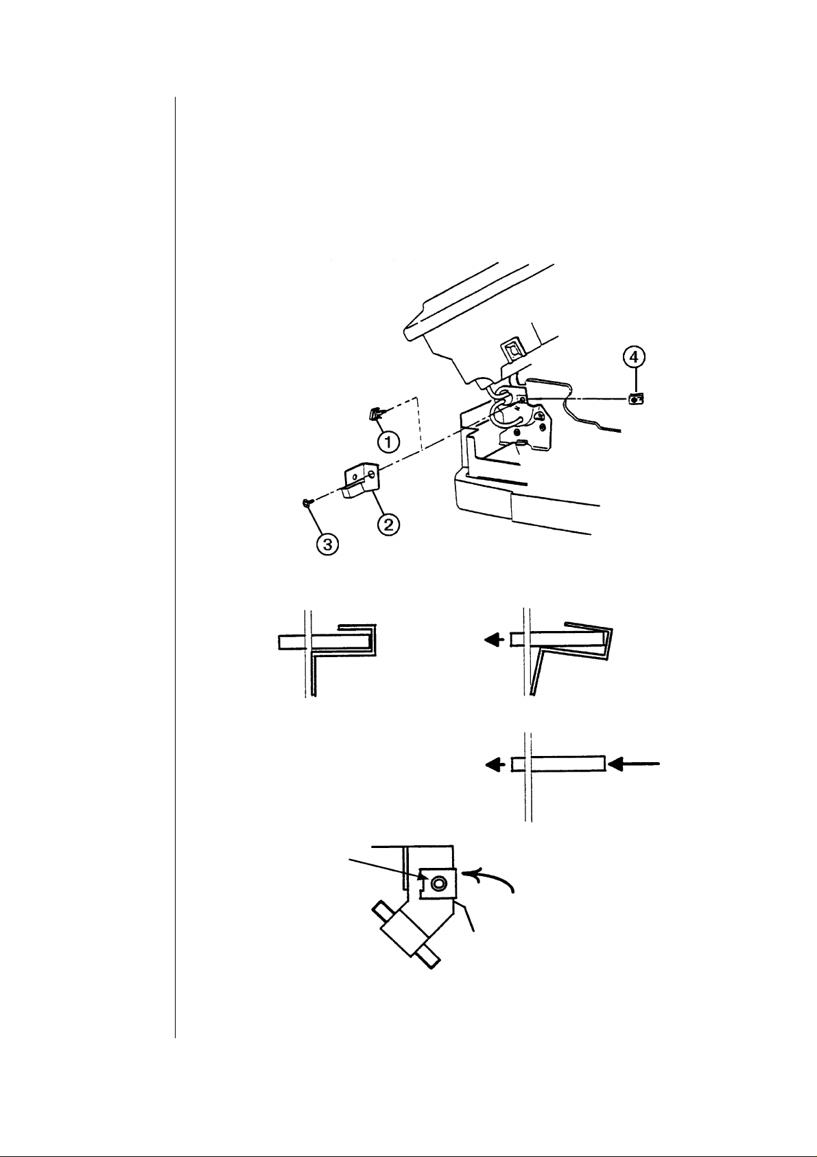
4) Install Torsion bar fixing bracket (Fig.2-[2]) using screw (Fig.2-[3]) and speed nut
(Fig.2-[4]) to fix the U-portion of the Torsion bar.
The screw must be installed into the hole at which the wire saddle was attached.
Note [3] : For machines where the tip of the torsion bar protrudes only a bit from the
fixing plate,the U-portion with the shank of a screwdriver to shorten the
U-portion (See Fig.3).
Proper attachment
Align the speed nut hole to
the angle hole.
[Fig.2]
Improper attachment
Need to insert the torsion bar
in the arrow direction.
If the screw does not engage with the
speed nut located on the back side,
slightly press the nut in the arrow
direction while tightening the screw.
2/3
[Fig.3]
Page 3

5) Fig.4 illustrates the torsion bar fixing bracket installed in the machine.
6) Insert wire saddle (Fig.5-[1]) in the hold of the torsion bar fixing bracket installed in
step 4.
7) Put wire (Fig.5-[2]) through the wire saddle installed in step 6.
[Fig.4]
[Fig.5]
8) Reattach the fusing unit cover removed in step 2.
9) Open and close the upper frame unit few times to check for proper open/close
operation.
5.Scope: This corrective action shall apply to machines manufactured in April 1996 thru August
1997.
All the stock must be reworked. Machines already delivered should be subject to the
corrective action on the occasion of maintenance, repair or the like.
Ref.
Model name Version P/G No.
No.
SF-2014/2114
SF-2214 Series
<Interchange>
1. Interchangeable. 4. Not interchangeable.
2. Current type can be used in place of new type.
New type cannot be used in place of current type.
3. Current type cannot be used in place of new type.
New type can be used in place of current type.
Parts marked with ‘‘ ’’ is important for maintaining the safety of the set. Be sure to replace these parts with
specified ones for maintaining the safety and performance of the set.
All ----
Current parts New parts
Parts code Parts code
LANGT0001QSZZ AK Torsion bar fixing bracket
LX-BZ4008SC0S AA Screw (Cup tight M4 × 8)
LX-NZ0001QSZZ AC Speed nut
LHLDW7008XCZZ AB Wire saddle
5. Interchangeable if replaced with same types of
related parts in use.
6. Others.
Price
rank
Parts name
Effec-
tive
change-
time
’97/9 6
Inter-
ability
Note
3/3
 Loading...