

Page 1

NOTEBOOK COMPUTER
PC-9820T
OPERATION MANUAL
â
Page 2

Notice for Users in the USA
FCC Statement
WARNING
modifications to this equipment not expressly approved by the
manufacturer could void the user’s authority to operate this equipment.
Note: This equipment has been tested and found to comply with the
limits for a Class B digital device pursuant to Part 15 of the FCC
Rules.
These limits are designed to provide reasonable protection against harmful
interference in a residential installation. This equipment generates, uses
and can radiate radio frequency energy and, if not installed and used in
accordance with the instructions, may cause harmful interference to radio
communications. However, there is no guarantee that interference will not
occur in a particular installation. If this equipment does cause harmful
interference to radio or television reception, which can be determined by
turning the equipment off and on, the user is encouraged to try to correct
the interference by one or more of the following measures:
- FCC Regulations state that any unauthorized changes or
•
Reorient or relocate the receiving antenna.
•
Increase the distance between the equipment and receiver.
•
Connect the equipment into an outlet on a circuit different from that
to which the receiver is connected.
•
Consult the dealer or an experienced radio/TV technician for help.
A shielded I/F cable is required to insure compliance with FCC
regulation for Class B computing equipment.
* As an ENERGY STAR Partner, SHARP has determined that this
product meets the ENERGY STAR guidelines for energy efficiency.
Declaration of Conformity
SHARP PERSONAL COMPUTER, PC-9820T
i
Page 3

This device complies with part 15 of the FCC rules. Operation is subject to the following
conditions:(1)this device may not cause harmful interference, and (2) this device must accept
any interference received, including interference that may cause undesired operation.
Responsible Party: SHARP ELECTRONICS CORPORATION
Sharp Plaza, Mahwah, New Jersey 07430
TEL: 1-800-BE-SHARP
About the Modem
This equipment PC-9820T complies with Part 68 of FCC rules. On the
bottom of this equipment is a label that contains, among other
information, the FCC registration number and ringer equivalence
number (REN) for this equipment. If requested, this information must
be provided to the telephone company.
The modem jack of this equipment complies with Sub-part F of Part 68
of FCC rules.
The REN is used to determine the quantity of devices which may be
connected to the telephone line. Excessive RENs on the telephone line
may result in the devices not ringing in response to an incoming call.
In most, but not all areas, the sum of the RENs should not exceed five
(5.0). To be certain of the number of devices that may be connected to
the line, as determined by the total RENs contact the telephone
company to determine the maximum REN for the calling areas.
If the terminal equipment causes harm to the telephone network, the
telephone company will notify you in advance that temporary
discontinuance of service may be required. But if advance notice isn't
practical, the telephone company will notify the customer as soon as
possible. Also, you will be advised of your right to file a complaint
with the FCC if you believe it necessary.
The telephone company may make changes in its facilities, equipment,
operations, or procedures that could affect the operation of the
equipment. If this happens, the telephone company will provide
advance notice in order for you to make the necessary modifications in
order to maintain uninterrupted service.
If trouble is experienced with this equipment, please contact Sharp
Electronics Corp. for repair and (or) warranty information (Refer to
ii
Page 4

the end of this section). If the trouble is causing harm to the telephone
network, the telephone company may request you remove the
equipment from the network until the problem is resolved.
The equipment cannot be used on public coin service provided by the
telephone company. Connection to Party Line Service is subject to
state tariffs. (Contact the state public utility commission, public
service commission or corporation commission for information.)
The Telephone Consumer Protection Act of 1991 makes it unlawful
for any person to use a computer or other electronic device, including
fax machines, to send any message unless such message clearly
contains in a margin at the top or bottom of each transmitted page or
on the first page of the transmission, the date and time it is sent and an
identification of the business or other entity, or other individual
sending the message and the telephone number of the sending machine
or such business, other entity, or individual. (The telephone number
provided may not be a 900 number or any other number for which
charges exceed local or long-distance transmission charges.) To
program this information, refer to the manual of the communication
software.
CAUTION about CD-ROM Drive
Use of controls or adjustments or performance of procedures other
than those specified herein may result in hazardous radiation exposure.
CAUTION about Battery
Danger of explosion if battery is incorrectly replaced. Replace only
with the same or equivalent type recommended by the manufacturer.
Discard used batteries according to the manufacturer's instructions.
Copyright
It is the intent of Sharp that this product be used in full compliance
with the copyright laws of the United States and that prior permission
be obtained from copyright owners whenever necessary.
iii
Page 5

Product Information and Customer Assistance
For Product Information and Customer Assistance:
Call:
1-800-BE-SHARP (237-4277)
Sharp Electronics Corp.
Sharp Plaza
Mahwah, NJ 07430
iv
Page 6

Notice for Users in Canada
About Modem
The Industry Canada label identifies certified equipment.
This certification means that the equipment meet certain
telecommunications network protective, operational and safety
requirements. The department does not guarantee the equipment will
operate to the user's satisfaction.
Before installing this equipment, users should ensure that it is
permissible to be connected to the facilities of the local
telecommunications company.
The equipment must also be installed using an acceptable method of
connection. In some cases, the company's inside wiring associated
with a single line individual service may be extended by means of a
certified connector assembly (telephone extension cord). The
customer should be aware that compliance with the above conditions
may not prevent degradation of service in some situations.
Repairs to certified equipment should be made by an authorized
Canadian maintenance facility designated by the supplier. Any repairs
or alterations made by the user to this equipment, or equipment
malfunctions, may give the telecommunications company cause to
request the user to disconnect the equipment.
Users should ensure for their own protection that the electrical ground
connections of the power utility, telephone lines and internal metallic
water pipe system, if present, are connected together. This precaution
may be particularly important in rural areas.
CAUTION
themselves, but should contact the appropriate electric inspection
authority, or electrician, as appropriate.
“The
device denotes the percentage of the total load to be connected to a
telephone loop which is used by the device. To prevent overloading,
the termination on a loop may consist of any combination of devices
Users should not attempt to make such connections
Ringer Equivalence Number
(REN) assigned to each terminal
v
Page 7

subject only to the requirement that the total of Ringer Equivalence
Number of all the devices does not exceed 5.”
About Battery
Caution:
Danger of explosion if battery is incorrectly replaced.
Replace only with the same or equivalent type recommended by the
manufacturer. Discard used batteries according to the manufacturer’s
instructions.
Attention:
Il y a danger d’explosion s’il y a remplacement incorrect de
la batterie. Remplacer uniquement avec une batterie du même type ou
d’un type recommandé par le constructeur. Mettre au rébut les batteries
usagées conformément aux instructions du fabricant.
Product Information and Customer Assistance
For Product Information and Customer Assistance:
Call: 1-905-890-2100 (Toronto Area)
1-800-56-SHARP (Outside Toronto)
Sharp Electronics of Canada Ltd.
335 Britannia Road East,
Mississauga, Ontario, L4Z 1W9
Canada
vi
Page 8

Notice for Users in Australia
Service Inquiries
Please contact your dealer for service if required or contact Sharp
Corporation of Australia on 1-800-807820 (free call) for referral to
your nearest Sharp authorised Service Centre. Details can be found on
the warranty card inserted with the documentation.
CAUTION
Danger of explosion if battery is incorrectly replaced. Replace only
with the same or equivalent type recommended by the manufacturer.
Do not dispose of large quantities of used Lithium batteries at the same
time.
Copyright
Copyright may exist in material you wish to record. Copying or
broadcasting such material without permission of the relevant licensees
or owners of the copyright is prohibited by law.
SHARP is not in a position to authorise the copying or broadcasting of
copyright materials and nothing in this OPERATION MANUAL
should be implied as giving that authority.
vii
Page 9

Notice for Users in the UK
IMPORTANT
The wires in this mains lead are coloured in accordance with the
following code:
BLUE: Neutral
BROWN: Live
As the colours of the wires in the mains lead of this apparatus may
not correspond with the coloured markings identifying the terminals
in your plug proceed as follows.
The wire which is coloured
terminal which is marked with the letter N or coloured black.
The wire which is coloured
terminal which is marked with the letter L or coloured red.
This apparatus must be protected by a 3A fuse in the mains plug or
This apparatus is approved under approval number NS/G
1234/J/100003 for indirect connection to the public telecommunication
system in the United Kingdom.
Service Inquiries
For customer and service support, please refer to the documentation
included with your notebook.
Copyright
Recording and playback of any material may require consent, which
SHARP is unable to give. Please refer particularly to the provisions of
the Copyright Act 1956, the Dramatic and Musical Performers
Protection Act 1958, the Performers Protection Acts 1963 and 1972
and to any subsequent statutory enactments and orders.
BLUE
BROWN
must be connected to the
must be connected to the
viii
Page 10

Notice for Users in Europe
This equipment complies with the requirements of Directives
89/336/EEC and 73/23/EEC as amended by 93/68/EEC.
Dieses Gerät entspricht den Anforderungen der EG-Richtlinien
89/336/EWG und 73/23/EWG mit Änderung 93/68/EWG.
Ce matériel répond aux exigences contenues dans les directives
89/336/CEE et 73/23/CEE modifiées par la directive 93/68/CEE.
Dit apparaat voldoet aan de eisen van de richtlijnen 89/336/EEG
en 73/23/EEG, gewijzigd door 93/68/EEG.
Dette udstyr overholder kravene i direktiv nr. 89/336/EEC og
73/23/EEC med tillæg nr. 93/68/EEC.
Quest' apparecchio è conforme ai requisiti delle direttive
89/336/EEC e 73/23/EEC, come emendata dalla direttiva
93/68/EEC.
H egkatastash autη
οδηγιων τηζ Ευρωπαïκηζ Ενωσηζ
73/23/EOK, ó
την οδηγια
Este equipamento obedece às exigências das directivas
89/336/CEE e 73/23/CEE, na sua versão corrigida pela directiva
93/68/CEE.
Este aparato satisface las exigencias de las Directivas
89/336/CEE y 73/23/CEE, modificadas por medio de la
93/68/CEE.
Denna utrustning uppfyller kraven enligt riktlinjerna 89/336/EEC
och 73/23/EEC så som komplette ras av 93/68/EEC.
Dette produktet oppfyller betingelsene i direktivene 89/336/EEC
og 73/23/EEC i endringen 93/68/EEC.
93/68/EOK.
ανταποκρινεται στιζ απαιτησειζ των
89/336/EOK
πωζ οι κανονισµοι αυτοι συµπληρωθηκαν απ
κατ
ó
ix
Page 11

Tämä laite täyttää direktiivien 89/336/EEC ja 73/23/EEC
vaatimukset, joita on muutettu direktiivillä 93/68/EEC.
CAUTION:
TO PREVENT ELECTRICAL SHOCK, DISCONNECT THE AC
CORD AND THE BATTERY BEFORE SERVICING.
CAUTION:
FOR A COMPLETE ELECTRICAL DISCONNECTION, PULL OUT
THE MAIN PLUG AND THE BATTERY.
VORSICHT:
UM DIE STROMZUFUHR VOLLSTÄNDIG ZU UNTERBRECHEN,
DEN NETZSTECKER HERAUSZIEHEN UND DIE BATTERIE
ÈNTFERNEN.
ATTENTION:
POUR UN ARRET TOTAL DU SYSTEME, DECONNECTEZ LA
PRISE DE COURANT SECTEUR ET LA BATTERIE.
VARNING:
FÖR TOTAL ELEKTRISK URKOPPLING, KOPPLA UR
KONTAKTEN OCH TA UR BATTERIET.
PRECAUCION:
PARA UNA COMPLETA DESCONEXION ELECTRICA
DESENCHUFE LA CLAVIJA DE LA RED Y LA BATERIA.
x
Page 12

Safety Precautions
General
•
Follow all cautions and instructions which may be marked on the
notebook.
•
Except as described elsewhere in this manual, refer all servicing to
qualified personnel. Immediately shut off the notebook and refer for
servicing under the following conditions:
when the power cord or plug is damaged or frayed
•
if liquid has been spilled on the notebook
•
if the notebook has been dropped or the cabinet has been damaged
•
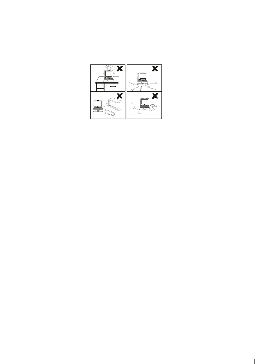
Location
•
Do not expose the notebook to direct sunlight.
•
Try to avoid dusty environments.
•
Keep the notebook away from any magnetic devices and TVs.
•
Keep the notebook away from excessive humidity or fluids such as
rain, snow, water spray, juice, coffee, steam, etc.
•
Do not move the notebook from a cold place to a warm place. A
temperature difference of more than 10°C (18°F) will cause
condensation inside the unit, which may damage the data.
•
Do not block or cover slots or openings on the cabinet to protect the
notebook from over heating.
•
Do not smoke near your notebook.
Usage
•
Never push any objects of any kind into cabinet openings. They may
touch dangerous voltage points or short parts that could result in fire
or electrical shock.
•
Turn off the notebook before installing or removing a peripheral
device.
•
Check the AC power cord and power connectors periodically for
damage. Replace the power cord immediately if damage is found.
xi
Page 13
•
Never subject your notebook to sudden shocks or extreme vibration.
•
Do not drop the notebook nor hit it with other equipment.
•
Do not scratch the surface of the LCD screen.
•
Turn off the notebook and disconnect the AC cord before cleaning.
Battery Pack Precautions
Handling
•
Never put the battery pack in a fire, as it could explode and cause
injury.
•
Do not attempt to open or alter the battery pack.
•
Do not place the battery where it might get hotter than 60°C (140°F).
•
Do not allow metal objects such as jewelry to short across the
battery terminals, as it could heat up and explode.
•
The battery includes a circuit breaker to help protect against short
circuiting. However, covering or pressing this breaker switch hard
could cause the battery to malfunction.
•
Do not allow liquids to come in contact with the battery pack.
•
Avoid dropping the pack or other violent shock.
•
Do not solder to the battery terminals.
Charging
•
Charge the battery pack only with the AC adapter included with your
notebook.
xii
Page 14

Discharging
•
Do not use the battery pack for any purpose other than powering the
notebook computer.
Storage
•
Store the battery pack in a cool and dry place. Never allow the
temperature to exceed 60°C (140°F) during storage.
•
Recharge the battery pack after storage, before use.
Lithium Battery Precautions
Caution
Danger of explosion if battery is incorrectly replaced. Replace only
with the same or equivalent type recommended by the equipment
manufacturer. Discard used batteries according to manufacturer’s
instructions.
Attention
Il y a danger d’explosion s’il y a remplacement incorrect de la batterie.
Remplacer uniquement avec une batterie du même type ou d’un type
équivalent recommandé par le constructeur. Mettre au rebut les
batteries usagées conformément aux instructions du fabricant.
Vorsicht
Explosionsgefahr bei unsachgemäßem Austausch der Batterie. Ersatz
nur durch denselben oder einen vom Hersteller empfohlenen gleichwertigen Typ. Entsorgung gebrauchter Batterien nach Angaben des
Herstellers.
Modem Precautions
•
Never install telephone wiring during a lightning storm.
•
Never install telephone jacks in wet locations unless the jack is
specifically designed for wet locations.
xiii
Page 15

•
Never touch uninsulated telephone wires or terminals unless the
telephone line has been disconnected at the network interface.
•
Use caution when installing or modifying telephone lines.
•
Avoid using the telephone function during a lightning storm. There
may be a remote risk of electric shock from lightning.
•
Do not use the telephone function to report a gas leak in the vicinity
of the leak.
xiv
Page 16

About This Manual
Notice
Information in this manual is subject to change without notice and does not represent a
commitment on the part of SHARP Corporation.
SHARP Corporation shall not be liable for technical or editorial errors or omissions contained
herein; nor for incidental or consequential damages resulting from the furnishing,
performance, or use of this material.
SHARP strongly recommends that separate permanent written records be kept of all important
data. Data may be lost or altered in virtually any electronic memory product under certain
circumstances. Therefore, SHARP assumes no responsibility for data lost or otherwise
rendered unusable whether as a result of improper use, repairs, defects, battery replacement,
use after the specified battery life has expired, or any other causes.
SHARP assumes no responsibility directly or indirectly, for financial losses or claims from
third persons resulting from the use of this product and any of its functions, such as stolen
credit card numbers, the loss of or alteration of stored data, etc.
Edition
1st Edition, September 1997.
Copyright
© 1997 SHARP Corporation
This document contains or refers to proprietary information which is protected by copyright. All rights
are reserved. Copying or other reproduction of this document is prohibited without the prior written
permission of SHARP Corporation.
Trademarks
Pentium is a registered trademark, and MMX is a trademark of Intel Corporation.
IBM and PS/2 are trademarks of International Business Machines Corporation.
Microsoft, MS-DOS, Windows, and the Windows Logo are registered trademarks of Microsoft
Corporation.
GlidePoint is a registered trademark of Cirque Corporation.
Sound Blaster is a trademark of Creative Technology Ltd.
TranXit and IntelliLink are trademarks of Puma Technology.
Profilink is a trademark of SYS Tech.
SuperVoice is a trademark of Pacific Image Communications, Incorporated.
VideoWork is a registered trademark of Newsoft Technology Corporation.
CardWorks is a trademark of SystemSoft Corporation.
All other brand and product names are trademarks or registered trademarks of their respective holders.
xv
Page 17

Recording Important Information
For future reference, please record the following information in the
spaces provided below.
Model Number:
Serial Number:
BIOS Version
Number:
Date of
purchase:
Dealer’s Name:
Place of
purchase:
Password:
The serial number is printed on a sticker located on the bottom of the
notebook. You will see the BIOS Version Number on the screen when
you turn on the notebook (BIOS stands for Basic Input Output
System).
xvi
Page 18
Manual Conventions
This manual uses a set of style conventions described below.
Notes and Cautions
A note icon informs you of a special technique or information
that may help you perform a task or better understand a
process.
A caution icon alerts you to something that may cause
problems or damage to hardware, software or data.
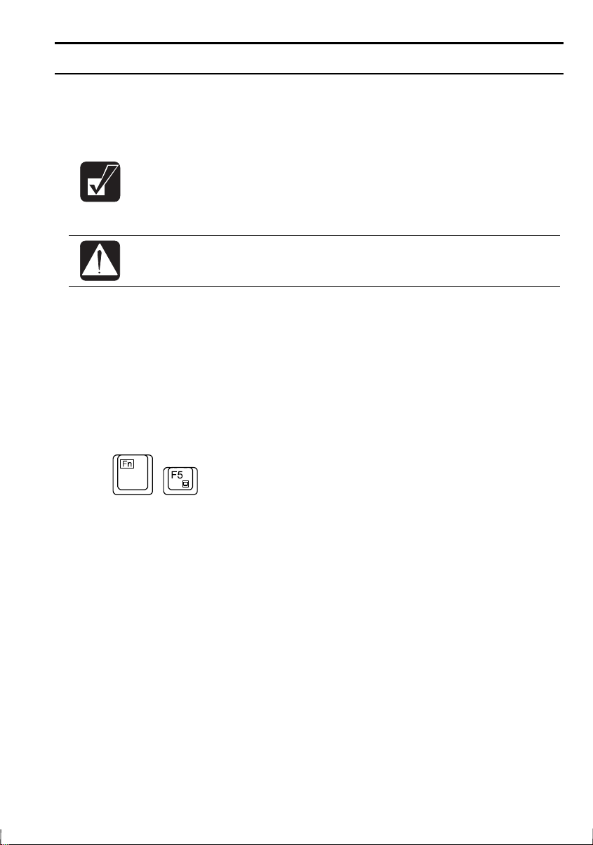
Key Labels on the Keyboard
shown in boldface:
Press
When more than one key are pressed simultaneously, the key labels are
separated by a plus (+) sign:
Restart your notebook by pressing
When necessary, important key combinations are shown in graphics:
Enter
are italicized with icons:
, when referred to in the instructions, are
to continue.
Ctrl+Alt+Delete
.
Sample Entries
following case, press the Enter key after you type the command:
C:\>DIR A:
Words/Texts on Screen
are italicized:
Double-click this icon to display the Power Properties window.
Set the item to Enabled.
Screens
you see on your notebook.
Section Titles
Refer to Infrared Communication section in Chapter 5.
reproduced in this manual may differ slightly from the screens
are shown in upper cases of different typeface. In the
Enter
, such as window titles or possible parameters,
in other parts of this manual are italicized:
xvii
Page 19

Table of Contents
Notice for Users in the USA .................................................................i
Notice for Users in Canada.................................................................. v
Notice for Users in Australia ............................................................. vii
Notice for Users in the UK ...............................................................viii
Notice for Users in Europe .................................................................ix
Safety Precautions............................................................................... xi
About This Manual ............................................................................ xv
Recording Important Information..................................................... xvi
Manual Conventions........................................................................ xvii
Table of Contents............................................................................xviii
Appearance of the Notebook ............................................................xxi
Chapter 1: Quick Setup
Unpacking the Notebook ..................................................................1-1
Connecting to AC Power ..................................................................1-2
Opening the Notebook ......................................................................1-3
Turning Power On ............................................................................1-4
Setting up Windows 95..................................................................... 1-5
Setting Original Wallpaper ...............................................................1-6
Shutting Down the System................................................................1-7
Chapter 2: Basic Operations
Choosing Power Source....................................................................2-1
Resetting the System.........................................................................2-2
Operating GlidePoint ........................................................................2-3
Using Keyboard ................................................................................2-5
Changing Bay Units..........................................................................2-7
Using Floppy Disks...........................................................................2-9
Using CD ........................................................................................2-11
Chapter 3: Battery and Power Management
Battery Pack......................................................................................3-1
Power Management ..........................................................................3-5
xviii
Page 20

Chapter 4: Peripherals
Using Peripherals ............................................................................. 4-1
Display ............................................................................................. 4-2
Printer............................................................................................... 4-5
Keyboard/Mouse .............................................................................. 4-7
Video System ................................................................................... 4-9
Audio System................................................................................. 4-10
Universal Serial Bus....................................................................... 4-12
Chapter 5: Communication Functions
Infrared Communication .................................................................. 5-1
Modem (US and Canada only)......................................................... 5-4
Chapter 6: Hardware Expansion
PC Cards .......................................................................................... 6-1
Memory Module............................................................................... 6-6
Chapter 7: Security Features
Passwords......................................................................................... 7-1
Security Slot..................................................................................... 7-2
Chapter 8: System Configuration Utility
Running the System Configuration Utility....................................... 8-1
Main menu ....................................................................................... 8-3
Advanced menu................................................................................ 8-4
Security menu................................................................................... 8-6
Power menu...................................................................................... 8-7
Exit menu ......................................................................................... 8-9
Appendixes
Maintenance and Care..........................................................................1
Power-On Self Test ..............................................................................2
System Mapping...................................................................................3
Pin Assignment ....................................................................................5
Specifications (including Options).......................................................8
xix
Page 21

Troubleshooting
Index
xx
Page 22
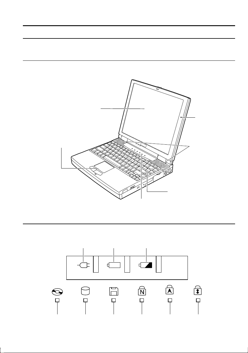
Appearance of the Notebook
Each number after the arrow indicates the page referring to the part.
General View
GlidePoint →
LCD Screen →
2-3
Status Indicators
AC Power Battery Power Battery Charge
1-3, 4-2
Status Indicators
Keyboard
Microphone
Stereo Speakers
2-5
→
CD-ROM Hard Disk Floppy Disk Num Lock Caps Lock Scroll Lock
Drive Drive Drive
xxi
Page 23
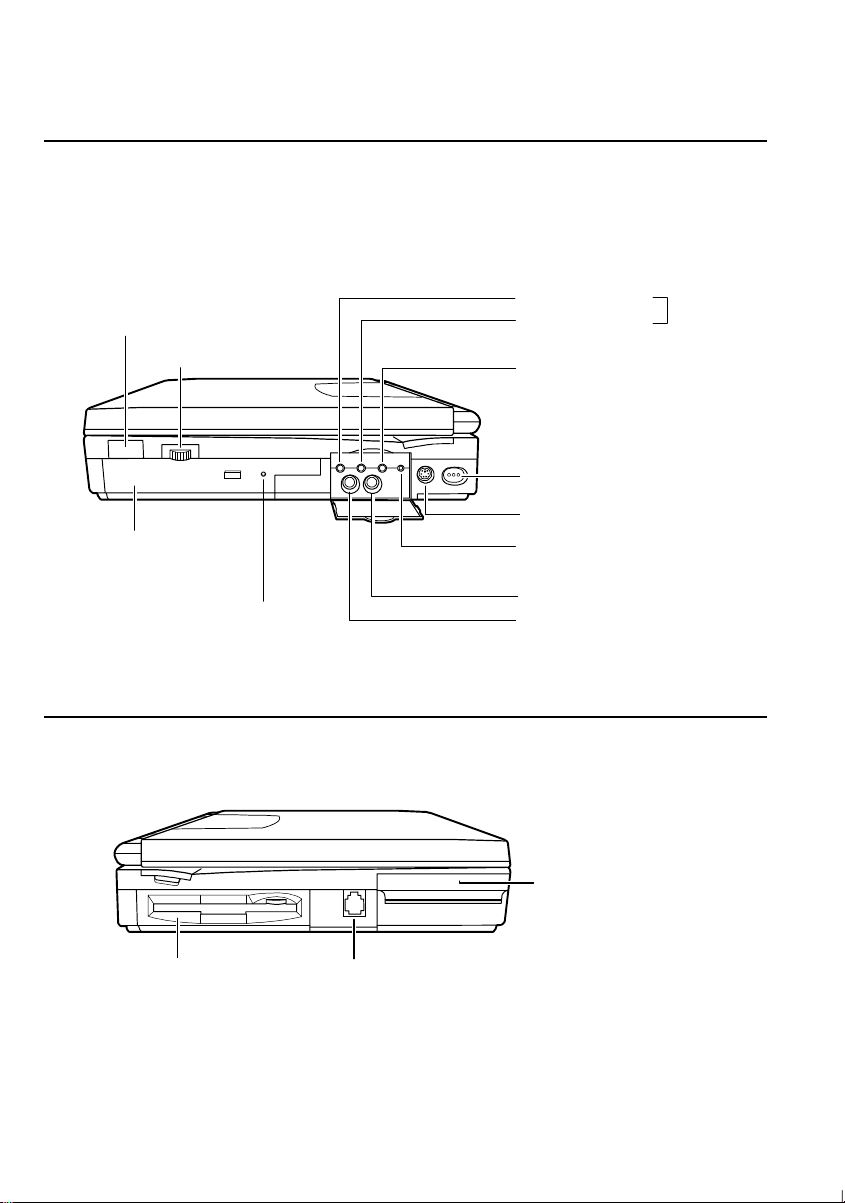
A
Right
IR Port
CD-ROM Drive →
Left
5-1
→
Volume Control
2-11
CD Tray Eject Hall →
T-5
udio Output Jack
Audio Input Jack
External Microphone Jack →
Power Switch
Keyboard/mouse Port →
DC Out
(only for future SHARP options)
Video Input Jack →
Video Output Jack →
→
1-4
4-9
→
4-2
4-10
4-7
4-11
Floppy Disk Drive →
Modem Jack →
2-9
(US & Canada only)
PC Card Slots →
5-4
6-1
xxii
Page 24
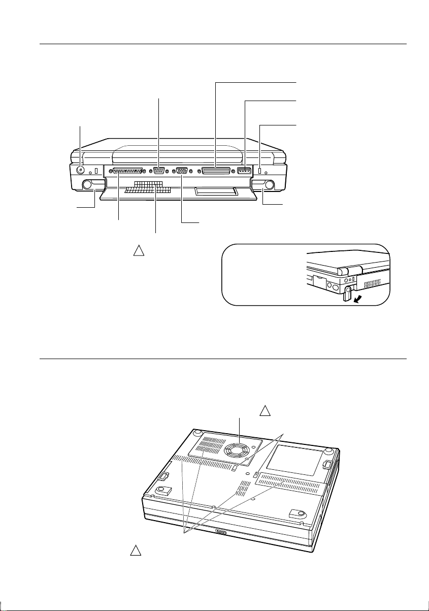
Rear
RS-232C Serial Port →
4-7
Expansion Connector
USB Port →
4-12
AC Adapter Jack →
Leg
Parallel Port →
Bottom
1-2
4-5
Ventilation Openings
( Do not cover )
!
External Monitor Port →
We recommend that
you should tilt the
notebook by rotating
its legs for ventilation.
Cooling Fan
( Do not cover )
!
Bay lock latch→
Security Slot →
Leg
4-2
2-7
7-2
Ventilation Openings
( Do not cover )
!
xxiii
Page 25

CHAPTER 1
Quick Setup
Your notebook is designed and pre-configured for easy setup and use. This chapter
describes the steps to get your notebook up and running as quickly as possible. Read
this chapter first.
Page 26

Page 27

Unpacking the Notebook
Your notebook comes securely packaged in a sturdy cardboard shipping carton.
Upon receiving your notebook, open the carton and carefully remove its contents. In
addition to this Operation Manual, the shipping carton should contain the following
items:
•
Notebook computer
•
AC adapter
•
AC adapter cable
•
Modem cable (only in US and Canada)
•
Battery Pack
•
Windows 95 CD-ROM
•
Backup CD-ROM
•
Setup Boot Disk
•
Introducing Microsoft Windows 95
•
Reinstallation Instructions
•
TranXit Quick Reference Guide
1
•
SuperVoice User’s Guide (only in US and Canada)
•
Sharp Import/Export User’s Guide (not available in Germany)
•
Profilink Windows (only in Germany)
•
Notice to Users
Carefully inspect each component to make sure nothing is missing or damaged. If
any of these items is missing or damaged, notify your dealer immediately. Be sure to
save the shipping materials and carton in case you need to ship or store the notebook
in the future.
Quick Setup 1-1
Page 28
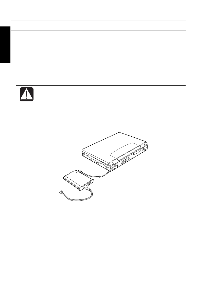
Connecting to AC Power
Your notebook works with either the rechargeable battery or AC power. See the
1
next chapter for more information on power sources. Before using the notebook for
the first time:
1. Make sure the notebook is turned off.
2. Connect the notebook and the AC adapter with the adapter cable.
3. Plug the AC power cord into the AC adapter.
Always use the AC adapter included with the notebook. Using other
•
AC adapters may damage the notebook.
Always hold the AC power cord by its plug when pulling off from the
•
wall outlet.
4. Plug the AC power cord into a wall outlet.
To Wall Outlet
1-2 Quick Setup
Page 29
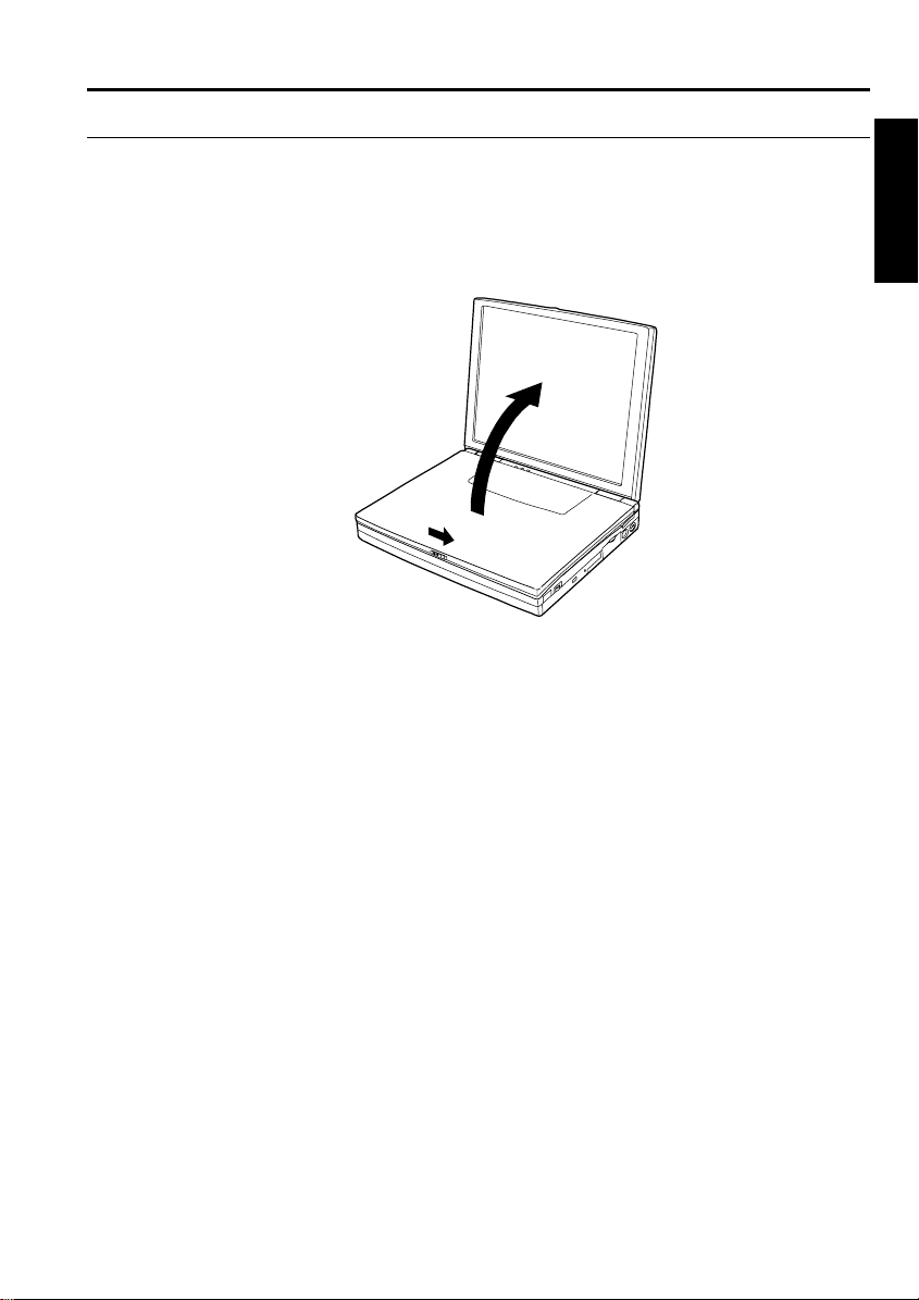
Opening the Notebook
To open your notebook:
1. Slide the display lock latch until the screen cover releases, and raise the cover.
2. Tilt the cover to a comfortable viewing position.
1
Quick Setup 1-3
Page 30
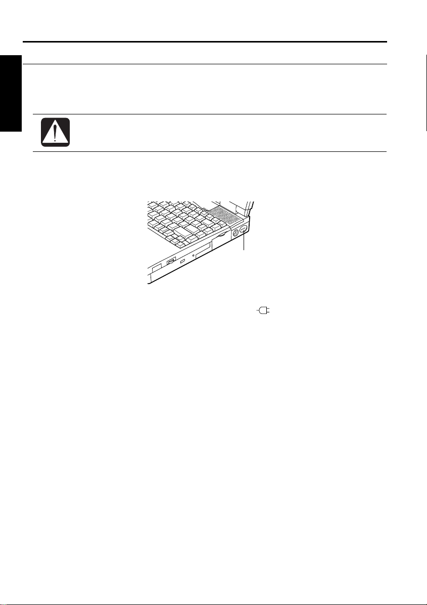
Turning Power On
To turn on the power:
1
1. Make sure your notebook is connected to the AC Power.
When using the notebook for the first time, be sure to connect it to an AC
power. If using the battery instead, you may not be able to complete the
Windows 95 setup when the battery does not have enough power.
2. Press the power switch.
When you turn on the notebook, the power indicator (
goes through a self test to detect any problems, and Windows 95 starts. When using
the notebook for the first time, a dialog box called the Windows 95 Setup wizard
appears to guide you through the Windows 95 setup.
Power Switch
) lights green, the notebook
1-4 Quick Setup
Page 31

Setting up Windows 95
The first steps in the setup process are as follows:
•
Gathering information
•
Configuring your computer
•
Restarting your computer
To set up Windows 95, follow the instructions on the screen. See also the manual of
Windows 95. It takes approximately 20 minutes to complete the entire setup
process.
1
Quick Setup 1-5
Page 32

Setting Original Wallpaper
After setting up Windows 95, set the SHARP original wallpaper in the following
1
procedure.
1. Double-click the Click me to set up SHARP Wallpaper icon at the upper right
corner of the screen.
2. When the message appears, click OK. The SHARP original wallpaper is
displayed on the screen.
1-6 Quick Setup
Page 33

Shutting Down the System
To turn off the notebook:
1. From the Start menu, select Shut Down.
2. Click Yes, and the notebook turns off automatically.
If you have not saved a file, a dialog box will appear asking if you want
to save it or not.
Do not turn off or reset the notebook while the hard disk or floppy disk
•
drive indicator is lit. Doing so may damage or even wipe out the data.
To protect the screen, always close the screen cover while the notebook
•
is off.
Before turning it back on, wait at least 10 seconds after turning off the
notebook. Turning the power off and on in rapid succession can damage
the notebook’s electrical circuitry.
1
Quick Setup 1-7
Page 34

Page 35

CHAPTER 2
Basic Operations
This chapter describes the basic operations you can perform on the notebook.
Page 36

Page 37

Choosing Power Source
You can use the notebook with one of the following power sources:
•
AC power from a wall outlet
•
Rechargeable battery pack
Use AC power whenever possible; rely on the battery pack only when AC power is
not available.
About the Power Indicators
The power indicators show the power status of your notebook.
Indicator Green Light Meaning
AC power On Operating with the AC power
Blinking Suspended to RAM (while operating with AC)
Battery power On Operating with the battery power
Blinking Suspended to RAM (while operating with battery)
Battery charge On (green) Fully charged
On (orange) Being charged
Blinking
(red)
For more information on Suspend to RAM, see Chapter 3.
Almost completely discharged.
(The warning beep sounds)
2
Using the AC Adapter
When connected to a wall outlet, the AC adapter provides power for operation or
charges the battery. The AC input voltage can range from 100 to 240 volts so that
you can use the notebook with the appropriate plug adapter.
The AC power cord included with the notebook is appropriate for the
voltage of your local area. If you attempt to connect the notebook to a
wall outlet other than in your local area, check the voltage of the outlet
and use an AC power cord appropriate for the outlet.
You can also install the AC adapter into the left-side bay. Refer to the section of
Installing a Bay Unit in this chapter for details.
Basic Operations 2-1
Page 38

Resetting the System
You may need to reset the system after adding hardware or software so that your
notebook will recognize the newly installed devices or software. When the message
appears after the installation, click OK, Yes, etc. to restart Windows 95.
You can also restart Windows 95 from the Start menu. Select Shut down; then,
2
Restart the computer?.
Warm Boot
If the system is locked up because of a software problem, you can reset or reboot the
system by pressing the Ctrl+Alt+Del keys simultaneously. Press the Ctrl+Alt+Del
keys again to restart the notebook.
Resetting may cause data loss. Use the software reset only if the normal
Windows 95 Shut Down does not work because of software malfunction.
Although resetting will not damage the system, you may lose the data you
are processing.
Power Switch
You can turn off the notebook with the power switch if you encounter hardware or
software problems which lock up the system.
2-2 Basic Operations
Page 39

Operating GlidePoint
Your notebook is provided with an integrated pointing device called GlidePoint.
Through GlidePoint, you can move the pointer, select an item among the menu, etc.
just like with a mouse. GlidePoint is also compatible with a PS/2 mouse.
Do not hit or scratch the surface of the GlidePoint with pointed objects
•
(such as a ballpoint pen).
Do not operate the GlidePoint with a moist finger. This may cause
•
GlidePoint to operate incorrectly.
Using the GlidePoint
Take a moment to become familiar with how the GlidePoint works.
2
Place Your Fingertip
Place your left or right hand next to the GlidePoint, resting your wrist naturally in a
relaxed manner. Place your thumb or finger on the GlidePoint.
Move Your Fingertip
The rectangular pad of the GlidePoint acts like a miniature duplicate of the display.
As you slide your fingertip across the pad, the pointer on the screen moves in the
same direction across the screen. The GlidePoint is very sensitive, and you do not
have to exert a lot of pressure on the pad. GlidePoint will respond to a light touch
from your fingertip.
Basic Operations 2-3
Page 40

Click, Double-click, and Right-click
To click, double-click, or right-click, you can use the left or right button just like
those of a mouse. Instead of clicking by pressing the left button, you can just tap
gently anywhere on the rectangular pad of the GlidePoint. For double-clicking, tap
twice gently.
Drag and Drop
2
You can move icons or windows by using “drag and drop.”
1. Position the pointer over the object such as an icon or window.
2. Press the left button; do not release it.
3. Holding down the button, move the pointer. The object moves together with
the pointer.
4. Release the button when the object comes to the appropriate place.
You can also drag and drop by tapping the GlidePoint.
1. Position the pointer over the object.
2. Gently tap twice on the pad.
3. On the second tap, keep your finger in contact with the pad.
4. Holding down the button, move the pointer. The object moves together with
the pointer.
5. Release the button when the object comes to the appropriate place.
Changing the Configuration
You can change the configuration of the GlidePoint, such as swapping left and right
buttons, changing the pointer size, etc. To adjust the configuration:
1. From the Start menu, select Settings - Control Panel.
2. Double-click the Mouse icon. The Mouse Properties window opens.
If you swap the left and right buttons, “ tapping” on the GlidePoint as
•
an alternative method of pressing the left button will no longer
function.
Your finger or palm may unconsciously touch the GlidePoint. This
•
touching is recognized as “tapping” or click, and the system works as
if you click. To avoid this inconvenience, you can disable the tapping
function in the Mouse Properties window. Select Tapping, uncheck
Tapping, and click OK.
2-4 Basic Operations
Page 41

Using Keyboard
Your notebook, equipped with the Windows Enhanced Keyboard, provides all the
functionality of a full-sized desktop keyboard. You should familiarize yourself with
the special notebook function keystrokes.
Windows Logo Keys
Opens the Windows Start menu.
Provides application-specific short-cut menu equivalent to the
right-clicking.
System Function Keys
Your notebook provides system function keys. When pressed in conjunction with
the Fn key, these keys set specific system parameters and are sometimes referred to
as “hot keys”.
Decreases the sound volume.
2
Increases the sound volume.
Do not use the above system function keys while recording sound.
Switches the display output between the LCD screen, TV and
external monitor (if connected). However, you should use this
key combination only when you cannot switch the display in
Windows 95. See the Display section in chapter 4 for details.
Decreases the LCD screen brightness.
Basic Operations 2-5
Page 42

Increases the LCD screen brightness.
2
Turns on and off the battery low warning beep.
Turns on and off the screen backlighting.
Puts the notebook in suspend mode (to RAM or to Disk,
according to the setup selection).
2-6 Basic Operations
Page 43

Changing Bay Units
When shipped, your notebook is equipped with the CD-ROM drive in the right-side
bay and with the floppy disk drive in the left-side bay. You can remove these drives
and replace them as follows:
Right-side Bay
•
Battery pack
•
Floppy disk drive
Left-side Bay
•
Battery pack
•
AC adapter
The AC adapter can only be installed in the left-side bay.
•
The CD-ROM drive can only be installed in the right-side bay.
•
You cannot use two floppy disk drives installed at the same time.
•
Removing the Bay Unit
1. Turn off the notebook.
2. Disconnect the AC adapter and all the peripheral devices.
3. Turn the notebook upside down on a flat place.
4. Slide the bay lock latch to the releasing position, and gently draw the unit out.
2
A bay unit may become hot after long use.
Basic Operations 2-7
Page 44

Installing a Bay Unit
1. Make sure the notebook is turned off and upside down.
2. Insert the unit into the bay with the connector forward.
When the unit is correctly installed, you hear a clicking sound, and the bay lock
latch returns to the original position.
2
When using the AC adapter in the bay, you do not need the adapter
cable.
2-8 Basic Operations
Page 45

Using Floppy Disks
You can use double-density (2DD) 720KB or high-density (2HD) 1.44MB floppy
disks.
Handling Floppy Disks
•
Do not open the shutter and touch the disk inside; otherwise, you will not be able
to read or write data to the disk.
•
Do not place floppy disks near magnets or heat source, in direct sunlight or in a
dusty place, etc.
•
Do not leave floppy disks on the built-in speakers; the magnets inside the speakers
may destroy the data in the disks.
•
Never subject a disk to sudden shocks or extreme vibration. Do not drop or bend
it. Do not place heavy objects on the disk.
•
Do not spill liquid onto the disk.
Inserting and Removing a Floppy Disk
Inserting
Hold the floppy disk with the arrow facing up and towards the drive. Slide the disk
into the drive until it clicks into place. When you set the floppy disk correctly, the
eject button pops out.
2
Always insert a floppy disk straight into the notebook.
•
When inserting the disk into the notebook, make sure it is not upside
•
down.
Do not push the disk into the notebook by excessive force.
•
Basic Operations 2-9
Page 46

Removing
Make sure the floppy disk drive indicator is not lit. Press the eject button to pop out
the disk slightly. Remove it and store it away properly.
2
Formatting a Floppy Disk
1. Make sure the floppy disk is not write-protected, and insert it into the floppy
disk drive.
2. Double-click My Computer on the desktop.
3. Click 3 ½ Floppy [A:]. From the File menu, select Format.
4. From the capacity drop-down list, select 1.44MB or 720KB.
5. Click Start to start formatting.
When you format a floppy disk, all the data in the disk are lost.
Backing Up Data
We recommend that you regularly backup the data on your hard disk drive in case.
Windows 95 has a backup function to let you easily back up your data.
From the Start menu, select Programs - Accessories - System Tools - Backup to start
the backup operation. For more information, see the Windows 95 Help.
Eject Button
Backup method may differ depending on software in use.
Installing and Uninstalling Floppy Disk Drive
The floppy disk drive is originally installed into the left-side bay; however, you can
install it into the right-side bay. See the previous section for the details.
2-10 Basic Operations
Page 47

Using CD
Compact disc (CD) is a storage medium with which you can read data, play music,
install and run programs, etc. The CD-ROM drive is available in the right-side bay
of your notebook.
Handling CDs
•
Do not write on either side of the disc, particularly the non-label side. Data is
read from the non-label side. Do not mark this surface.
•
Keep your discs away from direct sunlight, heat and excessive moisture.
•
Always hold the CDs by the edges. Fingerprints, dirt or water on the CDs can
cause noise or mistracking. If a CD is dirty or does not play properly, clean it
with a soft, dry cloth, wiping straight out from the center, along the radius.
Inserting a CD
You can operate the CD-ROM drive only when the notebook is on.
1. Make sure the CD-ROM drive indicator is not lit (it is supposed to blink
periodically because of Windows Auto Play function).
2. Press the eject button to open the CD tray slightly.
2
Basic Operations 2-11
Page 48

2
3. Gently pull out the tray.
4. Place your CD, label side up, on the tray.
5. Slightly press the center of the CD until it clicks into place.
6. Gently push the CD tray back into the notebook.
When inserting a CD, do not use force.
•
Make sure the CD is correctly inserted into the tray, then close the tray.
•
Do not leave the CD tray open. Also, avoid touching the lens in the
•
tray. If the lens becomes dirty, the CD-ROM may malfunction.
Do not wipe the lens with materials with rough surface (such as paper
•
towels). Instead, use a cotton swab to gently wipe the lens.
FDA regulations require the following statement for all laser-based
devices:
“Caution, Use of controls or adjustments or performance of procedures
other than those specified herein may result in hazardous radiation
exposure.”
2-12 Basic Operations
Page 49

Operating a CD
You can operate a CD with a software application named Sharp Player, which comes
with your notebook.
If audio or video files in a CD is not running smoothly:
1. Turn on or restart the notebook.
2. When the message <F2> to enter the System Configuration Utility appears,
press F2.
3. Click Power and uncheck the item Enable Power Management.
4. Click Exit and select Save Changes and Exit; then, click OK. The system
restarts.
5. From the Start menu, select Settings - Control Panel.
6. Double-click the Power icon.
7. Uncheck the item Allow Windows to manage power use on this computer.
8. Click OK and follow the instructions on the screen.
Removing a CD
1. Make sure the CD-ROM drive indicator is not lit.
2. Press the eject button to open the CD tray slightly.
3. Gently pull out the tray.
4. Remove the CD from the tray.
5. Gently push the CD tray back into the notebook.
When opening the CD tray, if the CD is still spinning, wait until it has
•
stopped, then remove it.
Do not remove the CD if the CD-ROM indicator LED is still lit;
•
otherwise the notebook may malfunction.
Maximum output and wavelength of the laser: 4.3mW, 780nm
•
2
CLASS 1LASER PRODUCT
LASER KLASSE 1
For uninstalling and reinstalling the CD-ROM drive, see the section of
Installing a Bay Unit.
Basic Operations 2-13
Page 50

Page 51

CHAPTER 3
Battery and Power Management
This chapter explains how to manage the notebook's power effectively and use
optional battery packs.
Page 52

Page 53

Battery Pack
When not connected to an external power source, your notebook operates with the
rechargeable battery pack. The duration of the battery life may be longer if the
notebook’s Power Management is active. To activate the power management:
1. Turn on or restart the notebook.
2. When the message <F2> to enter the System Configuration Utility appears,
press F2.
3. Click Power.
4. Check the item Enable Power Management and Max Power Saving.
5. Click Exit; then, Save Changes and Exit, and click OK. The system restarts.
An optional battery pack, which is the same type with the standard battery pack, is
also available.
• The amount of time a battery charge will last will depend on the
notebook usage. Applications which heavily use the peripherals, like
the floppy disk or the CD-ROM drive, will experience shorter power on
time.
• When the battery is not charged, your notebook may not operate
properly. Connect the AC adapter to charge the battery.
• If you see an error message in the booting time, press F2 to open the
System Configuration Utility. Following the instructions in Chapter 8,
set the System Configuration Utility and restart the system.
• When using the notebook for hours with the battery pack, enable the
power management, set the suspend-to-disk mode and check the item
Max Power Saving. Refer to the Power Management section in this
chapter and the Power section in Chapter 8.
3
Installing the Battery Pack
You can install the battery pack either in the right- or left-side bay of your notebook
as in the same way with other units. See Chapter 2.
• Before installing or uninstalling the battery pack, turn off your
notebook. If not, the system may malfunction or the data may be lost.
• Incorrect installation of the battery is dangerous. Replace the battery
only with Sharp's optional battery packs. Discard used batteries
according to the dealer's instructions and the proper disposal methods
for your area.
3-1
Page 54

The procedure for recharging an optional battery pack is the same as the
standard battery.
Initializing the Battery Pack
Before using the battery pack for the first time, be sure to initialize it. Initialization
includes discharging and fully recharging twice.
1. Make sure the battery pack is installed.
2. Turn on the notebook.
3
3. When the message <F2> to enter System Configuration Utility appears, press
F2 to open the System Configuration Utility.
4. Disconnect the AC adapter, and leave the notebook until the battery is
completely discharged and the system shuts down automatically.
5. Connect the notebook to the AC adapter and fully charge the battery pack.
6. Repeat the above steps 2-5.
• If you connect the notebook to wall outlet while discharging the
battery, the initialization is cancelled.
• You cannot initialize two battery packs at the same time.
Charging the Battery
1. Turn off the notebook.
2. Connect the AC adapter to the notebook.
3. Wait until the battery is fully charged. While the battery is being charged, the
battery charge indicator lights orange.
4. When the battery is fully charged, the battery charge indicator lights green.
The charging time may vary according to the status of the notebook.
Condition of Notebook Charging Time
Turned off / Suspended About 2 hours
Turned on About 4 hours
As a pre-caution, under long hours of operation, the notebook will stop
charging the battery automatically when it gets too hot. This will also
cause the battery charge indicator to go off. When the temperature is low
again, the system resumes charging the battery.
3-2
Page 55

Checking the Battery Level
1. From the Start menu, select Settings - Control Panel.
2. Double-click Power and read the battery level.
• Double-clicking the battery or AC plug icon on the taskbar shows the
battery power remaining.
• The battery power remaining is an approximate figure. The remaining
operating time expected may be different from the actual remaining
time, depending on the use of the notebook. If the the difference is too
large, initialize the battery pack as per above procedure.
Low Battery Indication
When the battery power becomes significantly low, the battery charge indicator
blinks red and the warning beep sounds. To stop the beep, press Fn + F10.
When the low battery power is indicated, save your data and turn off the notebook,
or connect the notebook to a wall outlet immediately. If not, the notebook will enter
the suspend-to-disk mode and will store the contents of the memory in the suspendto-disk partition. When your notebook suspends, do not turn on the notebook before
connecting to a wall outlet or installing a fully charged battery.
Even if you set Suspend Data to to RAM in the System Configuration
Utility, the notebook will be suspended to disk in case of low battery
power.
The remaining operating time depends on the power you are consuming. If you are
using the audio system, PC card slot or hard and floppy disk drives, your notebook
may consume more battery life.
See also the section about the power management in this chapter.
3
(
)
3-3
Page 56

Maintaining the Battery Pack
To keep the battery life long:
•
Initialize the battery pack especially when the difference between battery power
remaining and the actual operating time is too large.
•
Turn off your notebook when you are not using it.
Changing the Battery Pack
The capacity of a battery pack gradually decreases when used repeatedly (the
deterioration rate depends on the operating temperature and environment). If the
3
battery life becomes extremely short even after the initialization, you should change
the battery pack. Before using a new battery pack, initialize it. Note that your local
area may have rules of battery disposal.
Backup battery
In addition to the main battery, your notebook contains a backup battery to save
information in the System Configuration Utility (See Chapter 8). If your notebook
begins to lose its time and date setting, bring it to a local dealer for replacement of
this backup battery.
3-4
Page 57

Power Management
The power management saves electricity and extends battery life by controlling
power supply to built-in devices. Your notebook provides two types of power
management: BIOS (Basic Input Output System) power management and Windows
power management.
BIOS Power Management
The BIOS power management contains four modes. Your system enters a power
management mode, depending on the condition you have set in the System
Configuration Utility.
•
Idle mode
Decreases the CPU speed. Your system enters the idle mode if you enable it.
•
Stand-by mode
Stops the CPU clock and the power supply to the LCD screen and the hard disk
drive. Your system enters the standby mode if the specified time has passed
without any operation. To resume from the standby mode, press any key or touch
the GlidePoint.
•
Suspend-to-RAM mode
Stores the current status in the RAM and stops power supply to all but a few
essential components. Your system enters and resumes from the suspend-to-RAM
mode in the condition mentioned below. In the suspend to RAM, the AC power
indicator or the battery power indicator blinks green.
3
•
Suspend-to-disk mode
Saves the current condition in an area of hard disk, which is called “suspend-todisk partition,” and turns off the notebook. Your system enters and resumes from
the suspend-to-disk mode in the condition mentioned below.
3-5
Page 58

Switching to Each Mode
Idle Mode
3
Suspend Modes
The BIOS power management contains two types of suspend modes: suspend-toRAM mode and suspend-to-disk mode. You can define which suspend mode the
system enters in what conditions in the System Configuration Utility. See Chapter 8
for the details.
Your notebook enters a suspend mode in each of the following cases:
•
The specified time has passed without any operation
•
You select Suspend in the Start menu
Standby Mode
Suspend Mode
Full Power Mode (ordinary operation)
The power management does not switch to the mode you have set to
Disabled.
•
You press Fn+F12
•
The battery level is low (always suspended to disk)
•
The screen cover is closed (if you have selected Suspend in Cover Close of the
item Customize in the System Configuration Utility)
Your notebook resumes from the suspend-to-RAM mode in each of the following
cases:
•
You press any key
•
The time specified in Resume on Time in the System Configuration Utility appears
•
The modem receives a call (in US and Canada only)
3-6
Page 59

If you want to resume your system by a phone call:
1. Turn on the notebook.
2. When the message <F2> to enter System Configuration Utility appears,
press F2.
3. Click Power; then, Customize.
4. Set the item of Resume On Modem Ring to Enabled.
5. Click OK.
6. In the Exit menu, select Save Changes and Exit; then, click OK. The system
restarts.
7. From the Start menu, select Settings - Control Panel.
8. Double-click Power.
9. In the Power Properties dialog box, click Advanced.
10. Check the item of Wake up the computer when the phone rings.
11. Click OK twice.
Your notebook resumes from the suspend-to-disk mode by pressing the power
switch. The system restores the exact state as it was when entering the suspend
mode. If the notebook enters the suspend mode by low battery power, however, you
have to connect the notebook to AC power first. Suspend to Disk is useful when you
want to turn off the notebook and reopen the same windows after turning it on.
• With a fully charged battery, your notebook will remain in Suspend to
RAM mode for approximately 7 hours. If your battery becomes
completely discharged during Suspend to RAM, you will lose unsaved
data and will need to reboot your notebook. Therefore, if you are
planning to leave your notebook suspended for long periods of time, we
recommend Suspend to Disk.
• Usually 69MB of your hard disk space has been reserved as the
suspend-to-disk partition when your notebook shipped from the factory.
This means you can safely suspend to disk if the notebook has 64MB of
installed memory.
• When the system enters or resumes from Suspend to Disk mode, you
can see some flicker on the display. However, this is not a malfunction.
• If sufficient battery power does not remain, your notebook will not
resume from a suspend mode. To resume it from a suspend mode,
connect the notebook to the wall outlet.
• If a PC card does not work properly after your notebook resumes from
the Suspend to Disk, restart the notebook.
3
3-7
Page 60

• In the DOS mode, when the system enters the suspend mode after the
specified time has passed, the system clock stops. Reset it with the
System Configuration Utility.
When entering or resuming from a suspended mode, be sure to observe
the following precautions. Otherwise, the notebook may not operate
correctly after the notebook has resumed from the suspend mode.
• Do not turn off the notebook when the system is suspended to RAM.
The RAM contents will be lost.
• Do not operate the keyboard, GlidePoint or mouse in the process of
entering or resuming from the suspended mode.
3
• Before the system enters a suspended mode, terminate any
communications and make sure that no video or audio playback or
recording is in progress.
• Make sure the Windows power management is on. See the latter part
of this section.
Setting the Condition of BIOS Power Management
You can select one of the following conditions of the power management in the
System Configuration Utility:
z Max Performance
z Balanced Power Saving
z Max Power Saving
z Customize
If you select Customize, you can set:
z Hard Disk Power Down After
z Idle Mode
z Standby After
z Suspend After
z Suspend Data to
z Cover Close
z Battery Low Warning Beep
z VGA Activity
z Resume On Time
z Resume On Modem Ring
See Chapter 8 for details.
3-8
Page 61

Windows Power Management
In addition to the BIOS power management you can adjust in the System
Configuration Utility, your notebook complies with the Windows power
management. Utilizing the Windows power management, your notebook stops or
controls power supply to the hard disk or the display.
To Stop Power Supply to the Hard Disk
1. From the Start menu, select Settings - Control Panel.
2. Double-click Power.
3. Check the item Allow Windows to manage power use on this computer, and
click OK.
4. Select Disk Drive and set the power management.
5. Click OK.
When using communication software or if sound or voice pauses or skips
while played back, set the Windows power management to Off.
To Stop/control Power Supply to the Display
1. From the Start menu, select Settings - Control Panel.
2. Double-click Display.
3. Select Screen Saver.
4. Set the items in Energy saving features of monitor, and click OK.
Note that the power management may not seem to function in the
following conditions:
• When a clock is displayed on the taskbar
• When you are using an application program that accesses the hard
disk periodically
• When the IR monitor is available (refer to Chapter 5)
• When the USB port is enabled
(refer to the section of Universal Serial Bus)
• When Windows auto insert notification of CD is functioning
3
To determine if auto insert notification is functioning:
1. From the Start menu, select Settings - Control Panel.
2. Double-click System.
3. Select Device Manager.
4. Double-click CD-ROM; then, MATSHITA UJDA110.
5. Select Settings. You can see whether Auto insert notification is
3-9
Page 62

3
checked.
6. Click OK twice.
3-10
Page 63

CHAPTER 4
Peripherals
This chapter describes how to use peripheral devices of your notebook. You can
connect a printer, external monitor, external keyboard, mouse, or any other device to
the parallel, RS-232C serial or keyboard/mouse ports.
Page 64

Page 65

Using Peripherals
You can use the following peripheral devices. For the details, refer to the section
explaining each device, and contact your dealer.
• Be sure to turn off the notebook and the peripheral device before
connecting them.
Audio equipment
• Some devices have to be turned on after the notebook is turned on.
Audio equipment
Docking Station
4
USB
Video equipment
Video equipment
Microphone
RS-232C device
PrinterMouse Keyboard
Peripherals 4-1
CRT
Page 66

Display
You can use a CRT monitor or a TV set as an external monitor. To display only on a
CRT monitor, use a VGA-compliant model or model with 1024x768 or higher
resolution. To display on CRT and LCD simultaneously, use a model with
1024x768 or higher resolution.
Connecting a CRT Monitor
1. From the Start menu, select Settings - Control Panel.
2. Double-click Display.
3. Select Settings; then, Advanced Properties.
4. Select Monitor; then, Change….
4
5. If you see Show all devices in the dialog box, select it. If not, go on to the next
step.
6. Select the manufacturer and the model name of which CRT you want to
connect.
7. Click OK; then, Close.
8. Follow the instructions on the screen, if any.
9. Close the Display Properties window by clicking OK.
10. Turn off the notebook and the CRT monitor.
11. Open the connector compartment cover on the rear side of the notebook.
12. With a 15-pin monitor cable, connect the CRT monitor to the external monitor
port of your notebook. If the connector has screws, tighten them.
13. Turn on the CRT monitor and the notebook. The display is shown only through
the CRT monitor first.
14. Switch the display in the procedure in the latter part of this section..
Connecting a TV Set
1. Turn off the notebook and the TV set.
2. Using a video cable, connect the video output jack of the notebook to the TV
set.
3. Turn on the TV set, and set it to the video mode.
4. Turn on the notebook.
4-2 Peripherals
Page 67

5. From the Start menu, select Settings - Control Panel.
6. Double-click the Display icon.
7. Select the Display Device tab, and click OK.
8. In the Display Device box, select TV. Please ignore the warning message. It is
not a trouble.
9. Click OK.
10. Switch the display using the procedures below.
If you want to output sound, connect the audio output jack of your
notebook to the audio input jack of the TV set.
Switching the Display
1. From the Start menu, select Setting - Control Panel.
2. Double-click Display.
3. Click the Display Device tab. Display Control Plus for Windows 95 appears.
4. Click OK.
5. Select the d i splay. Although a warning message app ears, it is not a problem.
6. Click OK twice.
• Some CRTs, which are not compliant with your notebook, may not
display correctly.
• You can also switch the display in th e System Configuration Utility.
• While playing video or animation, you may not be able to switch the
display.
• If you have used the LCD only or the LCD and CRT simultaneously
with the resolution of 800x600 or less, the screen appears on the
display specified in the System Configuration Utility when restarting.
Changing Resolution and Number of Colors
When shipped, your notebook has the default resolution of 1024x768 and the color
palette of High Color (16 bit). To change the resolution and the number of colors:
1. From the Start menu, select Setting - Control Panel.
2. Double-click Display.
3. Click the Settings tab.
4
Peripherals 4-3
Page 68

4
4. Select the number of the colors in the Color palette, and select the resolution in
Desktop area. Refer to the table below.
5. Click OK twice.
6. Click Yes.
Resolutions and Colors you can choose
Resolution LCD CRT
640 x 480 256
64K
16M
800 x 600 256
64K
16M
1024 x 768 256
64K
16M
1280 x 1024 not available 256
1600 x 1200 not available 256 not available not available
256
64K
16M
256
64K
16M
256
64K
16M
64K
Number of Colors
Simultaneous Display
(LCD & CRT)
256
64K
16M
256
64K
16M
256
64K
16M
not available not available
256
64K
16M
not available
not available
TV
• You cannot switch to the display resoluti on and colors that ar e not
available.
• In the Color Palette, High Color (16 bit ) me ans 65,536 ( 64K) colors , and
True Color (24 bit) means about 16,770,000 ( 16M) colors .
• If you select True Color in the Color Palette,
* The drawing speed of screen is decreased,
* The screen seems corrupted w hen displayi ng video or ani mation, and
* The screen cannot display when you use a ZV por t compli ant PC car d.
4-4 Peripherals
Page 69

Printer
Before using the printer, read the printer manual.
To use a printer, complete the following procedures:
•
•
•
Connecting a Printer
1. Turn off the notebook and the printer.
2. Open the connector compartment cover on the rear side of the notebook.
3. With a 25-pin cable, connect the printer to the parallel port of your notebook.
Setting the System Configuration Utility
1. Turn on or restart the notebook.
2. When the message <F2> to enter System Configuration Utility appears, press
3. Click Advanced.
4. Select LPT Port; then, LPT1, Addr 378 IRQ7, and click OK.
5. Click Exit and select Save Changes and Exit.
6. Click OK. The system restarts.
Installing the Printer Driver
1. From the Start menu, select Settings - Printers.
2. Double-click Add Printer. Add Printer Wizard appears.
Connecting the Printer
Setting the System Configuration Utility
Installing the Printer Driver
If the connector has screws, tighten them.
.
F2
If your printer does not operate appropriately, change LPT Extended
Mode under the Advanced menu, referring to the printer manual.
4
Peripherals 4-5
Page 70

4
3. Click Next.
4. Select the manufacturer and the printer, and click Next. If you cannot see the
model name of your printer, you have to install the printer driver attached to the
printer. See the printer manual.
5. Select LPT1 and click Next.
6. Make sure the printer name is correct, and click Next.
7. Decide whether to print a test page, and click Finish. Before printing a test
page, make sure the printer is ready.
4-6 Peripherals
Page 71

Keyboard/Mouse
You can use a full size desktop keyboard or external mouse with your notebook. The
ways of connecting a PS/2 mouse and a serial mouse are slightly different as follows.
Connecting a Keyboard or PS/2 Mouse
1. Turn off the notebook.
2. Connect the cable from your mouse or keyboard to the keyboard/mouse port on
the right side.
3. Turn on the notebook.
• Never connect or disconnect the devices to the keyboard/mouse port
when the notebook is powered on. This may cause the notebook to
operate improperly.
• When connecting a mouse, you cannot use the GlidePoint.
Connecting a Serial Mouse
1. Turn off the notebook.
2. Open the connector compartment cover on the rear side.
3. Connect the serial mouse to the RS-232C serial port. Tighten the screws if they
are present.
4. Turn on the notebook.
5. When the message <F2> to enter System Configuration Utility appears, press
.
F2
6. Click Advanced.
7. Select COM Port; then, RS-232/Disabled or RS-232/Ir; then, OK.
8. In the Advanced menu, uncheck the item Pointing Device(PS/2 Mouse).
9. Click Save Changes and Exit in the Exit menu; then OK. The system restarts.
If the serial mouse you have connected does not operate appropriately:
1. Press the Windows logo key, select Settings with the arrow key and press
.
Enter
2. Select Control Panel, and press
Enter
.
4
Peripherals 4-7
Page 72

3. Select Mouse, and press
4. Pressing
5. Pressing
6. Select the manufacturer and model name with the arrow key, make sure the OK
button is highlighted and press
7. Pressing
8. Make sure Yes is highlighted, and pre ss
Using a mouse and an external keyboard
4
To use a serial mouse and an external keyboard (or ten key pad):
In the Advanced menu of the System Configuration Utility, set COM Port to RS-
232/Disabled or RS-232/Ir.
To use a PS/2 mouse and a serial ten key pad:
In the Advanced menu of the System Configuration Utility, check Pointing Device
(PS/2 Mouse).
Ctrl + Tab
Tab
Tab
When the serial mouse is active, you cannot use the GlidePoint nor a
PS/2 mouse.
, select the General tab.
, select Change, and press
, select Close, and press
Enter
.
Enter
Enter
.
Enter
Enter
.
.
. The notebook restarts.
4-8 Peripherals
Page 73

Video System
You can display video image from a TV set or VCR.
Connecting Video Equipment
1. Turn off the notebook and the video equipment.
2. Connect the video input jack of the notebook to the video output jack of the
video equipment (you can use a video cable in the market).
3. Turn on the notebook .
If you want to input sound, connect the audio input jack of your notebook
to the audio output jack of the video equipment.
Setting the Software
1. From the Start menu, select Programs - VideoWork - Presto!VideoWorks.
2. From the View menu, select Video Viewer.
Finishing the Video Viewing
1. Click the X button at the upper right corner.
2. From the File menu, select Exit.
3. Disconnect the cable.
4
Peripherals 4-9
Page 74

Audio System
Connecting audio equipment
1. Turn off the notebook and any connected peripherals.
2. Use the following audio cable for the connection:
To output the notebook’s audio signal t o the audio equipment:
Audio Equipment
4
Red
LINE IN (R)
White
LINE IN (L)
Black
Audio Output
Jack
To input audio signal from the audio equipment to the notebook:
Audio Equipment
LINE OUT (R)
Red
White
LINE OUT (L)
Black
Audio Input
Jack
3. Turn on the notebook.
When using the audio output jack, you cannot use the built-in speakers.
Notebook
Notebook
4-10 Peripherals
Page 75

Connecting an external microphone
1. Turn off the notebook.
2. Connect the external microphone to the external microphone jack on the right
side.
4
3. Turn on the notebook.
When using an external microphone, you cannot use the built-in
microphone.
Peripherals 4-11
Page 76

Universal Serial Bus
Your notebook has a new interface called Universal Serial Bus (USB). This
interface unifies the connection between computers and peripheral devices such as
keyboards, mice, speakers, modems, and printers. Through the USB , you could
connect/disconnect the peripherals without turning off the notebook. See manuals of
peripheral devices supporting USB.
To Use a USB-supporting Device
1. From the Start menu, select Settings - Control Panel.
2. Double-click System.
4
3. Select Device Manager.
4. If you find + mar k at Universal serial bus controller, click the mark. If you
find - mark, go on to the next step.
5. Double-click Intel 82371AB PCI to USB Universal Host Controller.
6. Uncheck Disable in this hardware profile.
7. Click OK.
To stop using the USB port, check Disable in this hardware profile in the above step
6.
It is not guaranteed that all USB devices in future will operate correctly.
4-12 Peripherals
Page 77

CHAPTER 5
Communication Functions
This chapter explains how to use infrared communications and the built-in modem.
Page 78

Page 79

Infrared Communication
Using the IR (infrared) port located on the right side of your notebook, you can
wirelessly communicate with infrared-equipped devices such as electronic
organizers, computers or printers. See the manual or online help of each application
for the details.
Positioning and Preparing the Notebook and the Target Device
To establish wireless communication:
1. Put your notebook on a flat surface.
2. Place the target device so that its IR port is in line with that of the notebook.
3. Adjust the distance between the IR ports to less than 20 inches (50 cm).
When using a Sharp electronic organizer, make sure the two IR ports are
within 4 inches (10 cm) apart.
Setting for Infrared Communication
You have to set the following items in the System Configuration Utility.
1. Turn on or restart your notebook.
2. When the message <F2> to enter System Configuration Utility appears, press
F2.
3. In the Advanced menu, make sure the Ir Mode is set to IrDA1.1 and COM Port
is set to Disabled/Ir, RS-232/Ir or MODEM/Ir.
4. In the Power menu, uncheck the item Enable Power Management.
5. Click Exit; then, Save Changes and Exit.
6. After the notebook restarts, turn off the Windows power management (see
Chapter 3).
• Do not enter a suspend mode during the infrared communication.
• Do not use a cellular phone or PHS near the notebook during the
infrared communication.
5
Communication Functions 5-1
Page 80

Setting for Each Application
The settings for each communications software are different as below; however,
most of them are automatically done.
5
Communications software IR Type
TranXit IrDA COM2 Disabled Disabled
Zrlink
(not available in UK and Germany)
Import/Export
(not available in Germany)
Profilink (only in Germany) ASK COM2 COM4
Windows 95 Communications software
(Direct Cable Connection, etc.)
•
IR Type
The two available IR types are usually IrDA (Infrared Data Association) and ASK
(Amplitude Shift Keying). An appropriate IR type for each application is
automatically selected.
•
Physical Port
The physical port for the application except TranXit is automatically set. The
physical port for TranXit is set when you install it.
•
Logical Port
To use TranXit, Zrlink, or Import/Export, disable the logical port:
1. From the Start menu, select Settings - Control Panel.
2. Double-click Infrared.
3. Select Options.
4. Uncheck Enabled infrared communication on:.
5. Click OK.
For users in US & Canada:
To use Import/Export, also set the port to COM5 in the application.
To use Zrlink, double-click Sharp IR, set ASK to COM4 and IrDA to COM5,
and click OK. Also set the port to COM4 in the application.
Physical
Port
ASK COM2 COM5 COM4
ASK COM2 COM5 COM4
IrDA COM2 COM4 COM5
Logical Port
(US & Canada)
Logical Port
(other
countries)
For users in other countries:
To use Zrlink or Import/Export, also set the port to COM4 in the application.
Although seeming contradictory to the above, this step is necessary.
5-2 Communication Functions
Page 81

After using TranXit, Zrlink, or Import/Export, enable the logical port.
SHARP IR Icon
For IrDA communication, your notebook is continuously emitting infrared rays to
search other IR devices. If necessary, you can temporally disable this infrared
emission.
1. From the Start menu, select Settings - Control Panel.
2. Double-click the SHARP IR icon.
3. Turn off the IR communication.
4. Click OK.
Other Communications software
For some communications software, you may have to change the assignment of the
logical port:
1. From the Start menu, select Settings - Control Panel.
2. Double-click SHARP IR.
3. Select Ports.
4. Change the settings, and click OK.
5. When the message You have changed the infrared communication port
appears, click OK.
5
Communication Functions 5-3
Page 82

Modem (US and Canada only)
You can use the built-in modem for data transfer, fax communication and voice
communication.
Connecting the Modem to Telephone Line
1. Turn off your notebook.
2. Connect one end of the included modem cable to the modem jack on the left
side of your notebook.
3. Connect the other end of the cable to the telephone line.
4. Turn on the notebook.
5
Connect the modem to the telephone line directly. Do not use a
distributor or allotter.
Setting the Modem in the System Configuration Utility
To use communication software:
1. Turn on your notebook.
2. Press the F2 key when the message <F2> to enter System Configuration
appears.
3. In the Advanced menu of the System Configuration Utility, set COM Port to
MODEM/RS-232, MODEM/Ir or MODEM/Disabled, and click OK. Namely,
COM1 has to be set for the modem.
4. In the Power menu, uncheck the item of Enable Power Management.
5. Click Exit; then, Save Changes and Exit; then, OK.
6. After the notebook restarts, turn off the Windows power management (see
Chapter 3).
5-4 Communication Functions
Page 83

Other Settings
1. From the Start menu, select Settings - Control Panel.
2. Double-click the Modems icon.
3. Set each item, following the instructions on the screen.
Set the COM port of the modem to COM1, when necessary.
Communication Speed
The built-in modem of your notebook applies the K56flex
method, which provides the following features:
•
The maximum communication speed is different between sending and receiving.
The receiving speed is 56000bps, and the sending speed is 33600bps.
•
The communication speed may vary depending on the traffic.
•
If the other side of your communication (such as an Internet provider) is not
compliant with K56flex, the maximum speed is 33600bps.
Using communications software
• Do not enter suspend mode while using communications software.
• You cannot use the speakerphone features in SuperVoice.
5
You have to set parameters such as modem speed (baud rate) and line type (pulse
dialing or tone dialing) within the communications software you are using. For
details, see the documentation or online help of the software.
Communication Functions 5-5
Page 84

Page 85

CHAPTER 6
Hardware Expansion
This chapter describes how to handle PC cards and increase memory of the
notebook.
Page 86

Page 87

PC Cards
Your notebook is equipped with two PC card slots which can accommodate two
Type II or one Type III card(s) conforming to the standards of the PCMCIA
(Personal Computer Memory Card International Association). When using a PC
card, see its manual.
Inserting PC Cards
You can insert/eject PC cards in the same way as floppy disks.
PC Card Slot Compatibility
Type II Type III ZV-port compliant CardBus compliant
Upper 3 N/A N/A 3
Lower 3 3 3 3
1. Open the PC card slot cover on the left side.
2. Insert the card into the appropriate slot with the label face up until it locks into
place. (You do not have to power off the notebook to handle PC cards when
using Windows 95). The PC card eject button pops up.
6
Insert the card correctly
If the card is not installed correctly, you hear the warning sound. In this
case, install the PC card driver, following the instructions on the screen.
6-1
Page 88

When Using Two PC Cards
If two PC cards do not work properly, you may have to open an IRQ (Interrupt
Request). For the procedure, see System Mapping in the Appendixes.
The IRQ is a signal to allow an input or output device to interrupt the CPU. In some
cases an IRQ number is assigned to one device; in other cases an IRQ number is
assigned to more than one device.
Ejecting PC Cards
1. From the Start menu, select Settings - Control Panel.
2. Double-click the PC Card icon.
3. In the PC Card Properties dialog box, click the icon of the PC card you want to
eject.
4. Click Stop.
5. When the message prompting you to eject the card, click OK.
6. Raise up the PC card eject button, and push it in. The PC card will be pushed
out slightly.
6
7. Remove the card, and close the slot cover.
Some PC cards may become hot after long use.
Installing the PC Card Driver
When you insert a PC card into the notebook, the driver for the PC card will usually
be installed automatically. If the driver is not installed automatically, a dialog box
for manual installation will appear. Follow the instructions on the screen to
complete the installation.
Some PC cards for ATA devices such as a hard disk may not be recognized
correctly. In this case, see your Windows manual or call the SHARP customer
assistance center for technical support and specific installation instructions.
6-2
Page 89

ZV-Port Compliant PC Card
To use a ZV-port compliant PC Card, you need to install CardWorks. When not
using ZV-port compliant PC Cards, uninstall CardWorks.
Installing CardWorks
1. From the Start menu, select Programs - Accessories - Notepad.
2. From the File menu, select Open.
3. In the field of File name, type:
C:\CONFIG.SYS
and click Open.
4. Change the following lines
device=c:\windows\emm386.exe ram
to
device=c:\windows\emm386.exe NOEMS X=C000-CBFF
X=D000-DFFF
5. From the File menu, select Save.
6. Close Notepad.
7. Restart the system.
8. Insert the Backup CD-ROM in the CD-ROM drive.
9. From the Start menu, select Run.
10. In the field of Open, type:
R:\PCCARD95\SETUP.EXE
and press Enter. The message appears.
11. Follow the instructions of the installation program and click Next.
12. When the message Please insert disk 2 appears, click OK.
13. To the question on reading Readme, click No.
14. When the message Setup complete, click Finish. The system restarts.
15. From the Start menu, select Programs - MS-DOS Prompt.
16. Type:
MKDIR C:\VPMUTIL
and press Enter.
17. Type:
COPY R:\VPM\ADJUST.EXE C:\VPMUTIL
18. Type:
EXIT
and remove the CD-ROM.
6
6-3
Page 90

6
To adjust the screen, select My Computer - C: - Vpmutil - Adjust.
Uninstalling CardWorks
1. From the Start menu, select Programs - Accessories - Notepad.
2. From the File menu, select Open.
3. In the field of File name, type:
C:\CONFIG.SYS
4. Remove the following lines:
rem SystemSoft/PCCard configuration –- Do not
remove EMM386.EXE
rem SystemSoft CardWorks(TM) PCMCIA drivers:
device=C:\CARDWORK\CARDXTND.SYS
device=C:\CARDWORK\SSCBO2.SYS /NUMADA:1
\ADA1SKTS:2
device=C:\CARDWORK\CS.SYS /POLL:1
device=C:\CARDWORK\CSALLOC.EXE
device=C:\CARDWORK\CARDID.SYS
5. From the File menu, select Save.
6. Close Notepad.
7. From the Start menu, select Settings - TaskBar.
8. Select the Start Menu Programs tab, and click Remove.
9. Select CardWorks; then, Remove.
10. Click Yes.
11. Confirm CardWorks is removed and close the dialog box.
12. From the Start menu, select Settings - Control Panel.
13. Double-click System.
14. Select the Device Manager tab.
15. Double-click PCMCIA socket and select 02 Micro OZ6832 CardBus
Controller.
16. Click Remove, and confirm the removal.
17. Repeat the above steps to remove another 02 Micro OZ6832 CardBus
Controller.
6-4
Page 91

18. Click Refresh.
19. Make sure both of 02 Micro OZ6832 CardBus Controller are attached with the
X marks.
20. Click Close; then, Yes.
21. Restart the system.
To use other PC cards, you need the following settings after the above steps:
1. From the Start menu select Settings - Control Panel.
2. Double-click the PC Card icon.
3. In the PC Card Wizard, make sure No is selected, and click Next.
4. In the next window, make sure No is selected, and click Next again.
5. Click Finish.
6. Click Yes. The system automatically shuts down.
7. Turn on the notebook again.
8. From the Start menu, select Settings - Control Panel.
9. Double-click the System icon.
10. Select the Device Manager tab.
11. Double-click PCMCIA socket and make sure two 02 Micro OZ6832 CardBus
Controllers are displayed (without X marks).
12. Click OK.
13. Double-click the My Computer icon.
14. Double-click the C: icon.
15. Click the CardWork folder.
16. From the File menu, select Delete.
17. Click Yes, and delete all the files in the folder, following the instructions on the
screen.
6
6-5
Page 92

Memory Module
Your notebook comes with 32MB of standard memory. You can expand the
memory size by installing 32MB or 64MB optional memory modules.
Standard Option Total
32MB 64MB
32MB
64MB 96MB
Checking the Memory Size
1. From the Start menu, select Settings - Control Panel.
2. Double-click System. The memory size is shown in the lower-right part of the
Installing a Memory Module
6
1. Turn off the notebook, and disconnect the AC adapter and peripheral devices.
2. Slide down the latch on the left edge of the notebook.
64MB 64MB 128MB
It is necessary to remove the original standard 32MB Memory Module
and replace it with a 64 MB Memory Module, if a total of 128 MB of
RAM is desired.
window.
Do not handle the memory module where static electricity is easily
•
generated such as on the carpet.
Before installing the memory module, carefully discharge static
•
electricity from your body by touching an unpainted metal area.
Avoid touching the integrated circuits on a memory module. Handle
•
all components by the edges.
Keep the memory module in the anti-static wrapping until you are
•
ready to install it.
6-6
Speaker Cover
Page 93

1. Slide the speaker cover toward right, and remove it.
2. Pull out the tape and raise the keyboard.
Tape
3. Remove the keyboard from the notebook (handle the keyboard carefully).
4. Put the keyboard on soft cloth so that it could not be damaged.
Memory Socket
Be careful not to damage this part.
6
6-7
Page 94

5. Inclining the memory module, match the notched part of the memory module
with the projected part of the memory socket on the notebook.
6
6. Push the memory module into the slot firmly at an angle of 20 degrees.
20
º
7. Gently push the memory module down until you hear a clicking sound.
8. Put the keyboard back to its original position.
9. Make sure the keyboard is reinstalled correctly, and replace the speaker cover.
6-8
Page 95

10. While pressing down, slide the speaker cover toward left until you hear a click.
Uninstalling the Memory Module
1. Remove the speaker cover and the keyboard, following above steps 1-6.
2. Slightly bend the two latches outward until the memory module is released.
3. Remove the memory module.
4. Install the keyboard and the speaker cover, following above steps 10-12.
6-9
6
Page 96

Page 97

CHAPTER 7
Security Features
This chapter describes how to set up security to limit access to the notebook.
Page 98

Page 99

Passwords
If you have set a password, only a person who knows the password can start the
system of your notebook. See also Chapter 8.
If you lose your password, you will be unable to access the notebook or
change the configuration. Make sure to select a password you will never
forget, or write it down and protect it in a secure place. Otherwise, you
will have to contact your dealer for assistance.
Setting the Password
1. Turn on or restart the notebook.
2. When <F2> to enter System Configuration Utility appears, press F2.
3. Click Security; then, System Password.
4. Type your password, and press Enter. The password can be up to eight
characters.
5. Type the same password for confirmation, and press Enter.
6. Click the item Enable Password. The X mark is attached.
7. Click OK - Exit - Save Changes and Exit - OK. The notebook restarts and asks
the password you have set.
Deleting the Password
1. Turn on or restart the notebook.
2. When <F2> to enter System Configuration Utility appears, press F2.
3. Click Security; then, System Password.
4. In the item Enter old Power-On Password, type the password and press Enter.
5. At the next two items, just press Enter without typing any letters.
6. Click the item Enable Password. The X mark is deleted.
7. Click OK - Exit - Save Changes and Exit - OK. The notebook restarts.
7
7-1
Page 100

Security Slot
You can prevent theft by using a security cable and the security slot on the rear side
of your notebook.
7
7-2
 Loading...