

Sharp LZ0P3820 Datasheet

#’
-SHARP
SPECIFICATIONS
Product Type : l’7%FG lens-integrated CMOS Color Area Sensor for CIF
Yodel No.
%This specifications contains 24 pages including the cover.
If you have any objections,please contact us before issuing purchasing order.
CUSTOMERS AcCEpTANCJ3
DATE :
BY:
LZOP3820
PRESENTED
I Dept. General Manager
REVIEWD BY:
PREPARED BY:
Product Development Dept. II
CCD Development Center
Integrated Circuits Devel
SBABP CORPORATION

SHARP
l
Handle this document carefully for it contains material protected by international
copyright law. Any reproduction, full or in part, of this material is prohibited
without the express written permission of the company.
l
Vhen using the products covered herein, please observe the conditions written herein
and the precautions outlined in the following paragraphs. In no event shall the
company be liable for any damages resulting from failure to strictly adhere to these
conditions and precautions,
(1) The products covered herein are designed and manufactured for the following
application areas. Vhen using the products covered herein for the equipment
listed in Paragraph (2>, even for the following application areas, be sure
to observe the precautions given in Paragraph CU. Never use the products
for the equipment listed in Paragraph (3).
*Office electronics
OInstrumentation
#Machine tools
SAudiovisual equipment
*Home appliances
Xommunication equipment other than for trunk lines
and
LZOP3820
measuring equipment
(2) Those contemplating using the products covered herein for the following
equipment which demands high reliability, should first contact a sales
representative of the company and then accept responsibility for incorporating
into the design fail-safe operation, redundancy, and other appropriate
measures for ensuring reliability and safety of the equipment and the overall
system.
*Control and safety devices for airplanes, trains, automobiles, and other
transportation equipment
*Mainframe computers
*Traffic control systems
*Gas leak detectors and automatic cutoff devices
,Bescue and security equipment
*Other safety devices and safety equipment,etc.
(3) Do not use the products covered herein for the following equipment which
demands extremely high performance in terms of functionality, reliability, or
accuracy.
-Aerospace equipment
Xcfnmunications equipment for trunk lines
Control equipment for the nucJear power
BMedical equipment related to life support, etc.
(4) Please direct all queries and comments regarding the interpretation of the
above three Paragraphs
to
a sales representative of the company.
industry
0 Please direct all queries regarding the products covered herein to a sales
representative of the company.

SHARP
LZOP3820
CONTENTS
1
1. GENERAL DESCRIPTION
2. ARRANGEMENT OF PIXELS AND COLOR FILTORS
3. BLOCK DIAGRAM
4. PIN CONFIGURATION
5. PIN DESCRIPTION
6. ELECTRIC CHARACTERISTICS~
7. IMAGING CiiABACTERISTICS
8. LENS SPECIFICATIONS
9. TIMING DIAGRAM
. 10. DESCRIPTION OF SERIAL DATA
1 1. EXAMPLE OF STANDARD OPERATING CIRCUIT
12. SPECIFICATION FOR BLEMISH
,..1,1,.111.1...,1...*.1...1.1,.,.,...**.*.
~,I,*o.I.,Ill.l,.II,,.II1II1*1.L,~I~
I.,,,I,..I...I..II.,.1O,IIOI..1,111..
ll,lI1111,1,1111,,,11,,11,1111,1.0,1~111
II.,,,.I,,.11.1..,,I.,,.L,,III,,
II.I......11,1,,I.,,,,.I..I..I,.I
..,.11...1.1,,1.1,,..1....,.1..1..1..
,,1,,,,1111.11111,,1,1~1,11~..~,..~~I1~..1
11111,1,,..1111.1111.011111,1
. . . . ..*..0..111,.1.10,11..1..
1**.111,*111.1,0
,.*..'.ll,,,*,l,ltl.
P. 2
P. 3
P. 4
P. 5
P. 6
P. 7
P. a
p. 9
P. IO
P. 13
P. 16
P. 17
1 3. CAUTIONS FOR USE
14. PACKAGE OUTLINE AND PACKING SPECIFICATI(JN
,1,,1.1,11..10,,,1....‘.,,~......,.~...
Illl,,l#ll.~l*t
P. 18
P. 20
SHARF,
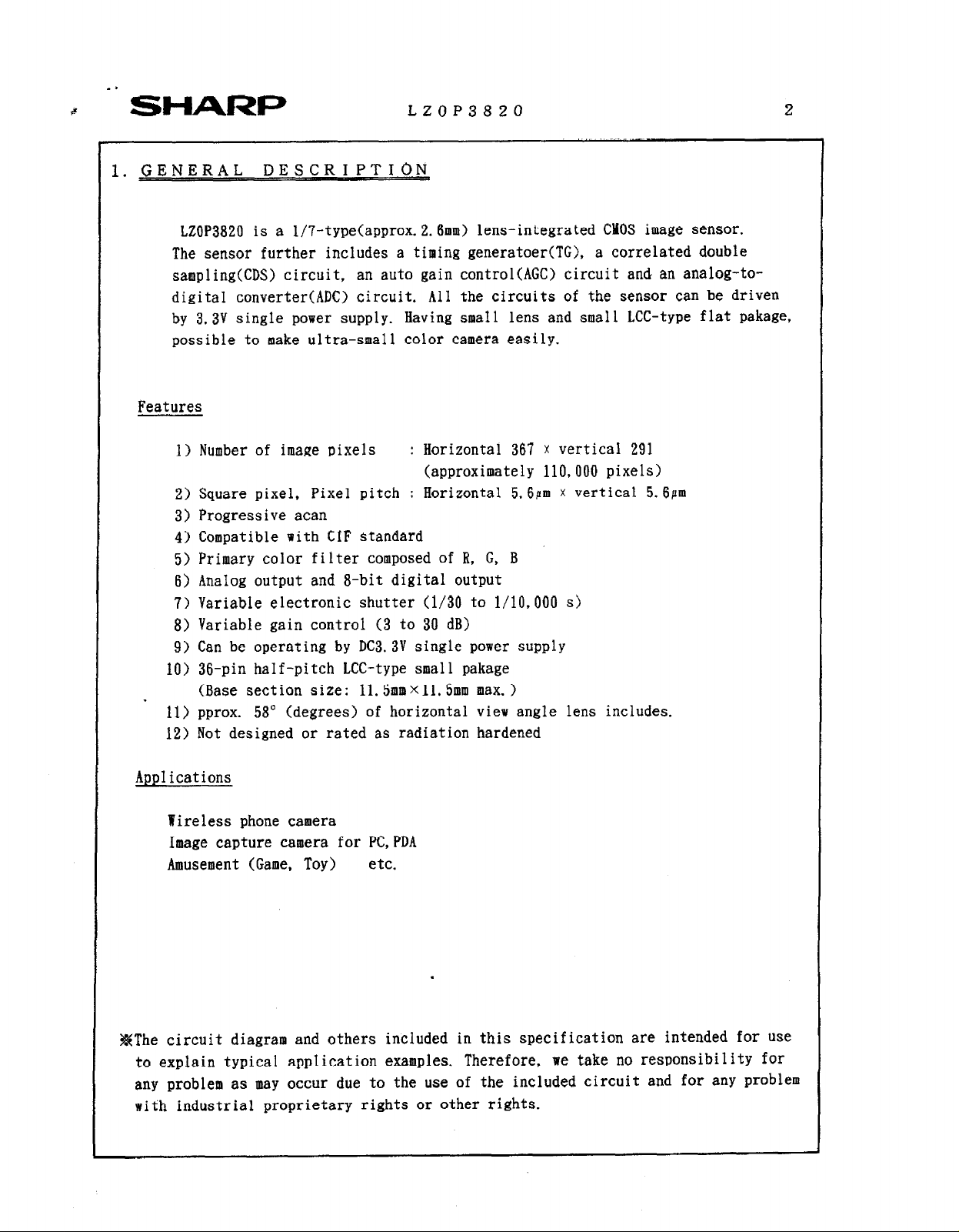
l.GENERAL DESCRIPTION
LZOP3820 is a l/7-type(approx.2.6mm) lens-integrated CMOS image sensor.
The sensor further includes a timing generatoer(TG), a correlated double
sampling(CDS) circuit, an auto gain control(AGC) circuit and an analog-to-
digital converter(ADC) circuit. All the circuits of the sensor can be driven
by 3.3V single power supply. Having smaI1 lens and small LCC-type flat pakage,
possible to make ultra-small color camera easily.
Features
1) Number of image pixels : Horizontal 367 x vertical 291
2) Square pixel, Pixel pitch : Horizontal 5.6Pm x vertical 5.6pm
3) Progressive acan
4) Compatible with CIF standard
5) Primary color filter composed of B. G, B
6) AnaIog output and a-bit digital output
7) Variable electronic shutter (l/30 to l/10,000 s>
8) Variable gain control (3 to 30 dB)
9) Can be operating by DC3.3V single power supply
10) 36-pin half-pitch LCC-type small pakage
(Base section size: ll.5mmXll. 5mm max. )
11) pprox. 58” (degrees) of horizontal view angle lens includes.
12) Not designed or rated as radiation hardened
LZOP3820 2
(approximately 110,000 pixels)
Applications
Yireless phone camera
Image capture camera for PC,PDA
Amusement (Game, Toy) etc.
.
#The circuit diagram and others included in this specification are intended for use
to explain typical application examples. Therefore,
any problem as may occur due to the use of the included circuit and for any problem
with industrial proprietary rights or other rights.
we take no responsibility for
SHARP
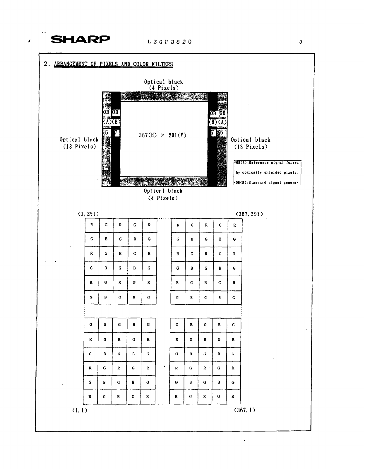
2. -T .OF PIXELS AND COLOR FILTERS
LZOP3820 3
Optical black
(4 Pixels)
Optical black
(13 Pixels)
(1
.
367(H) x 291(V)
Optical black
(4 Pixels)
, 1
R
. . ..-
Optical black
(13 Pixels)
by opticaliy shielded pixels
OB(B):Standard signs1 genera-
(367.291)
lG IRI
(367.1)
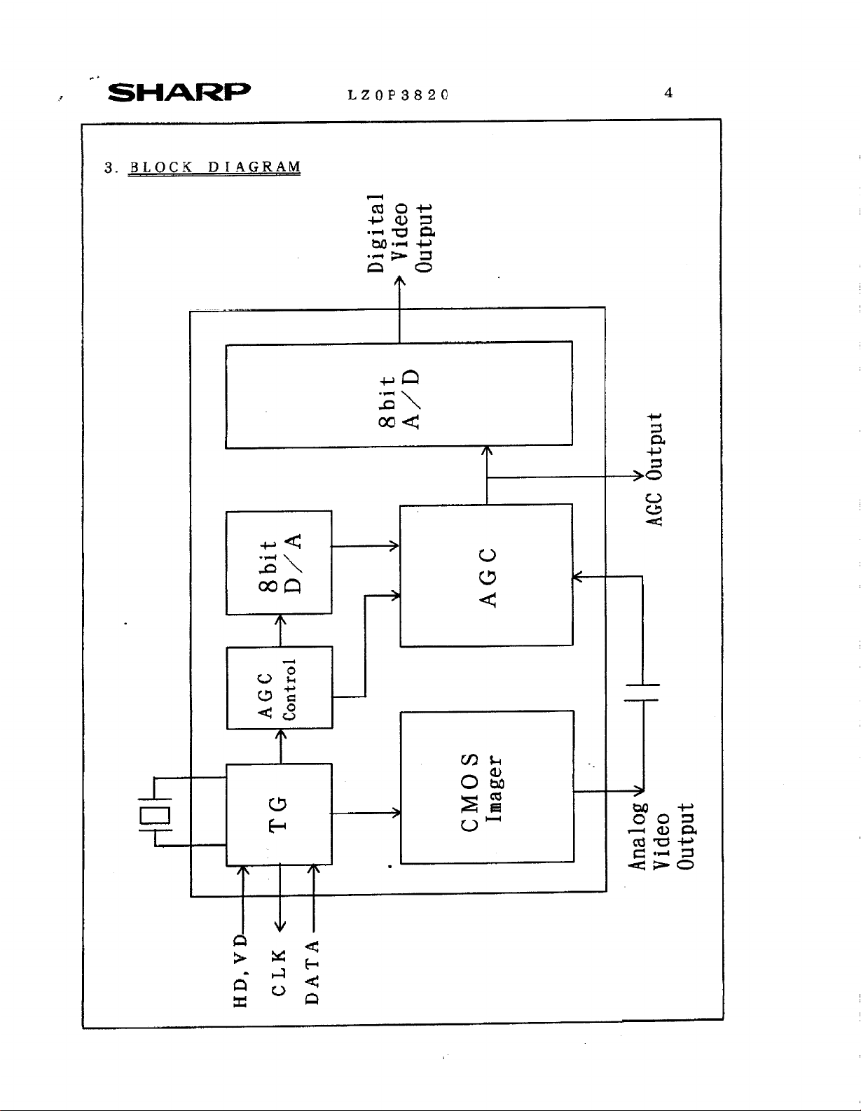
D/A
+ 8bit
Digital
output
-+ Video
8bit
A/D
V
>
AGC
AGC
I
+
HD,VD-
+ Control
TG
3
CLK t-
DATA-
I
V
.
output

:*
-’ SHARP
4.PIN CONFIGRATION
LZOP3820
VIEW>
BIAS1
SCLK
CLP
OFS
BIAS2
SICOUT
SIGIN
ACND
AVDD
N. c.
LZOP3820
N. c.
D5
D4
D3
D2
Dl
DO
DGMD
DVDD
*a
a
SHARP
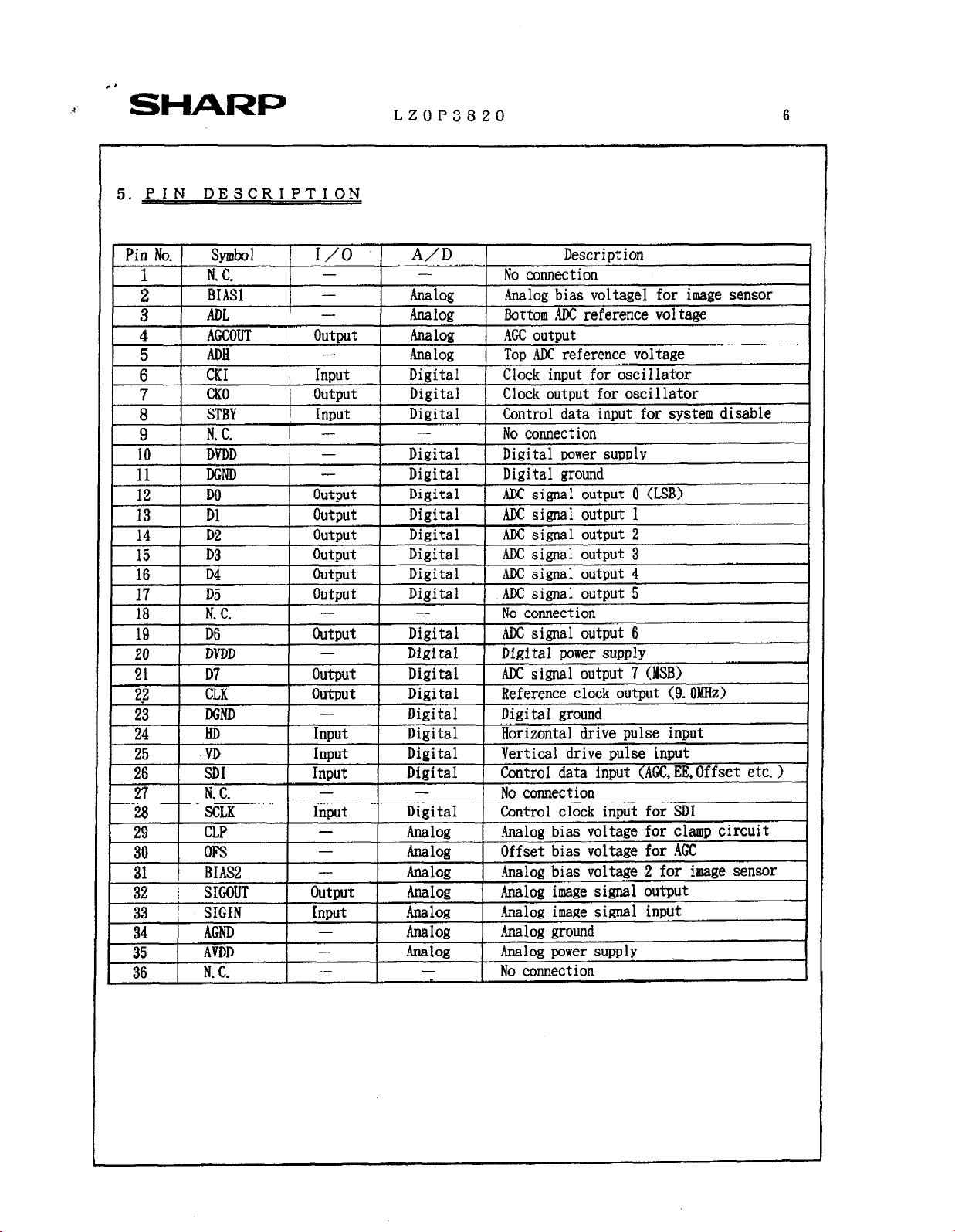
5. PIN DESCRIPTION
LZOP3820 6
STBY
N. C.
DVDD
DGND
ii
13 Dl
14 D2
15 D3
16 D4
17 D5
18 1
19 I D6
I
20
21 D7
sl.7 -7 ” n ‘ .I n1 -~:L-, l--d------- -1--1. -__A.-__A /n rxlR,-\
zg
23 1 DGND I - 1 Digital 1 Digital mound
27 1 N. c. - 28
29 CLP - Analog
DO
N.
C.
DVDD
1 LLh 1 uuqlur 1
HD
VD
I
I iDI
1 SCLK Input Digital 1 Control clock input for SD1
._
rs
BIAS2
I++--
33
34
t=k-
35
1 36 1
SIGOUT
SIGIN
AGND
AVDD
N. C.
Ir;
-
-
1 I
I OutDut I Digital 1 ADC signal output 0 (L SB)
outp,t Digital 1 AJX si&l output 1
output Digital ,
output
output Digital ,
Output Digital 1 AIX s&al output 5 I
- -
I outDut I
-
output Digital ADCsigna _
! I
1 Input
1 hlDUt I
I I I
I Input I
- Analog
Digital 1 Digital power supply
I Di
.gital 1 Digital ground I
1
ADC simal
Digital 1 AM: signal output 3 1
Digital I ADC signal output 6
Digital Digital power SUDDEN 1
mgisal I nererence
-- ~~
Digital Horizontal drive pulse input
Digital Vertical drive Dulse inmt
Diiital I Control data input (AGCiEE,Offset etc. > 1
I ADC siml output 4 I
1 No connection
I No connection
I -~-~~-~ --
Analog bias voltage for clamp circuit
Offset bias voltage for AGC
Analog bias voltage 2 for image sensor
Analog image signal output
-Analog image signal input
Analog ground
Analog power supply
No connection
OutDut 2 I
1 OUtDUt 7
CIWK ouepu~ \Y. urhuu/
(MSB)
I
J
 Loading...