

Sharp LT135A Datasheet
Hall Device
LT135A
■ Features
¡
Small temperature coefficient of the Hall voltage
¡
Good linearity of the Hall voltage
¡
Small imbalanced voltage
¡
Directly DC voltage applicable
LT135A
Hall Voltage 240mV GaAs Hall Device
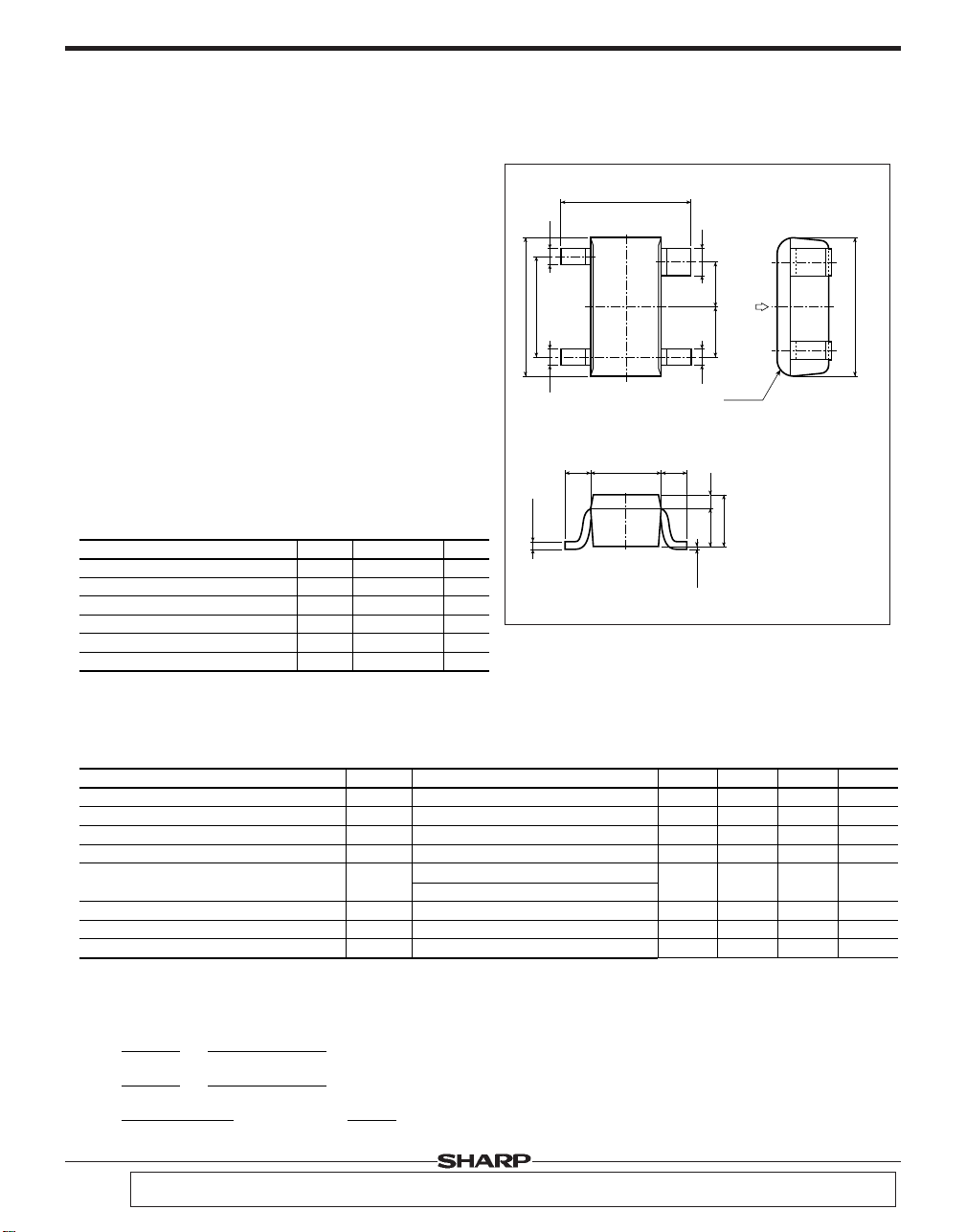
■ Outline Dimensions
2.7±0.3
0.40.4
1
4
0.6
(Unit : mm)
■ Applications
¡
Brushless motors
VCR, CD, CD-ROM, FDD
¡
Measuring equipment
Gauss meters, magnetic substance detectors
¡
Noncontact sensors
1.9
2.9±0.2
2
(0.85)(0.95)
N
3
0.4
4-R0.2
Microswitches, tape-end detection
¡
Other magnetic detection
■ Absolute Maximum Ratings
Control voltage
Parameter
Control current
Power dissipation
Operating temperature
Storage temperature
Soldering temperature
*1
Soldering time : 10 seconds
*1
Symbol
V
P
T
T
T
C
I
C
D
opr
stg
sol
(Ta=25˚C)
Rating
12
15 mA
150
-20 to +125
-55 to +150
260
+0.10
-0.06
Unit
0.16
V
mW
˚C
As for dimensions of tape-packaged products, refer to page 44 .
˚C
˚C
1.5±0.2
0.6 0.6
0.30.8
(0to0.15)
Terminal connection
1:V
2:V
+0.2
-0.1
3:V
1.1
4:V
C
Input
H
Output
C
Input
H
Output
■ Electrical Characteristics (T
Parameter
*1
No-load Hall voltage
Imbalanced voltage
*2
Input resistance
Output resistance
Drift of imbalanced voltage vs. temperature
Temperature coefficient of Hall voltage
Temperature coefficient of input resistance
Linearity of Hall voltage
*1 No-load Hall voltage is nearly proportional to Vc (within the range of 1 to 6V) at temperatures of -20˚C to + 125˚C.
Keep the voltage within the allowable power dissipation range.
*2 Imbalanced ratio is in +/-12% within the range of Vc=1 to 6V.
Symbol
H
V
V
HO
R
IN
R
OUT
|∆VHO|
β
α
γ
C
=6V, B=100mT
V
V
C
=6V, B=0mT
M
=1mA, B=0mT
I
I
M
=1mA, B=0mT
C
=6V, B=0mT, Ta=-20˚C to 25˚C
V
C
=6V, B=0mT, Ta=25˚C to 125˚C
V
IC=6mA, B=100mT, T1=-20˚C, T2=125˚C
IM=1mA, B=0mT, T1=-20˚C, T2=125˚C
IC=6mA, B1=50mT, B2=100mT
Conditions
VH=VM-VHO
β=
α=
1
V
H(T1
)
1
IN(T1
)
R
{K
H(B2
{K
H(B1
)-KH(B1)}
)+KH(B2)}
γ=
H(T2
)-VH(T1)}
{V
X
XX100
{R
(T
IN(T2
(T
2-T1
)-RIN(T1)}
2-T1
X2X100,
X100
)
)
H
=
K
V
H
(ICXB)
V
M
:Observed Hall voltage
V
HO
:Imbalanced voltage
H
:Sensitivity
K
MIN
200
-15
650
1 300
-
-
-
-
TYP.
240
-
800
1 600
5
-0.03
0.2
2
MAX.
280
15
950
1 900
-
-
-
-
2.9±0.2
a
=25˚C)
Unit
mV
mV
Ω
Ω
mV
%/˚C
%/˚C
%
In the absence of confirmation by device specification sheets, SHARP takes no responsibility for any defects that may occur in equipment using any SHARP devices
shown in catalogs, data books, etc. Contact SHARP in order to obtain the latest device spcification sheets before using any SHARP device.
LT135AHall Device
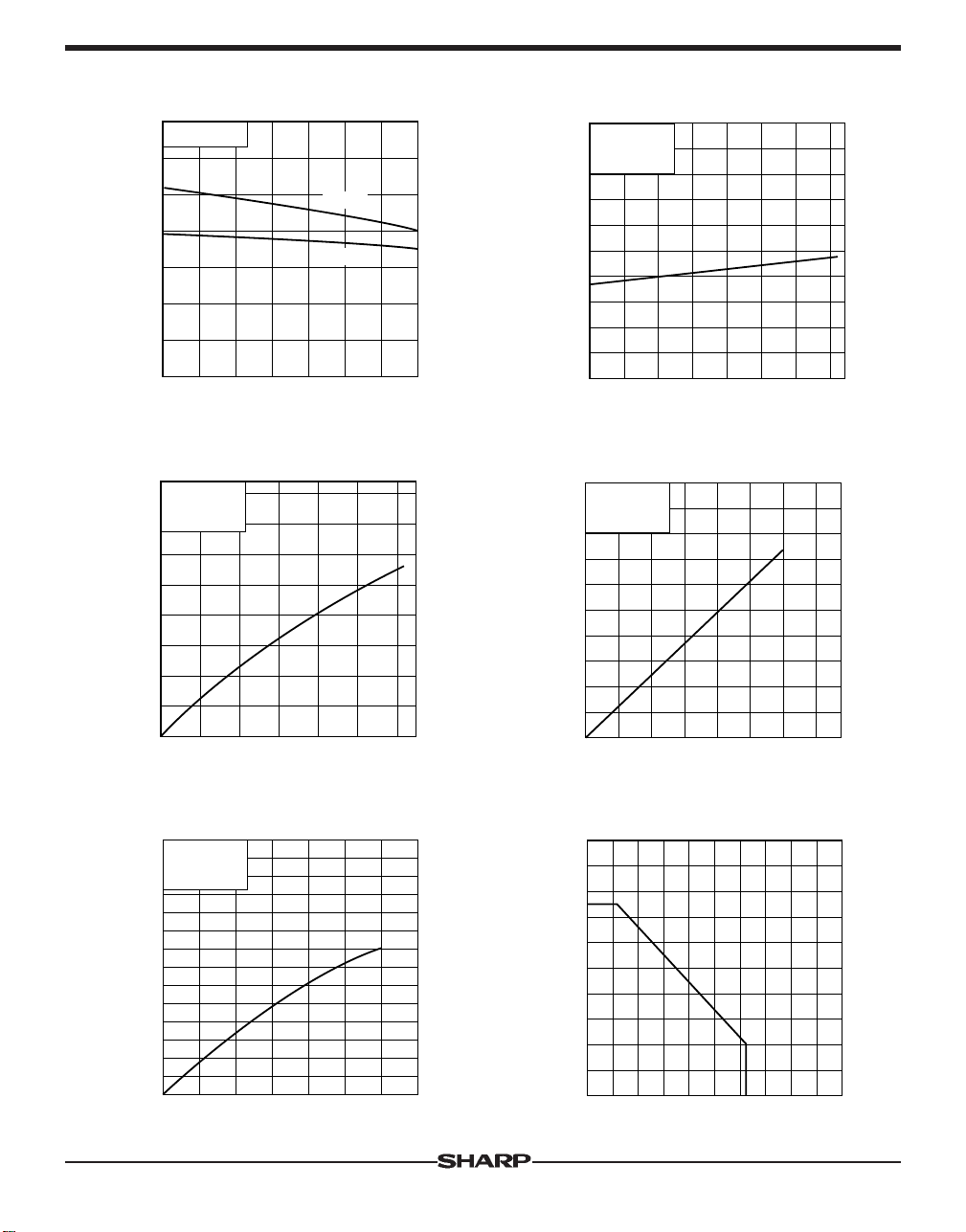
Fig. 1 Hall Voltage vs. Ambient
Temperature
B=100mT
300
250
(mV)
H
200
150
100
Hall voltage V
VC=6V
IC=6mA
50
0
-20 0 8040 120
Ambient temperature Ta (˚C)
Fig. 3 Hall Voltage vs. Magnetic Flux
Density
1 600
1 400
1 200
(mV)
H
1 000
Hall voltage V
VC=6V
a
=25˚C
T
800
600
400
200
0
0 500400100 200 300 600
Magnetic flux density B (mT)
Fig. 5 Hall Voltage vs. Control Voltage
B=100mT
T
a
=25˚C
(mV)
H
600
500
400
Fig. 2 Input Resistance vs. Ambient
Temperature
2 000
1 600
1 200
Input resistance RIN (Ω)
B=0mT
M=1mA
I
800
400
0
-20 0 8040 120
Ambient temperature Ta (˚C)
Fig. 4 Hall Voltage vs. Control Current
600
B=100mT
a=25˚C
T
400
300
200
Hall voltage VH (mV)
100
0
08412
Control current IC (mA)
Fig. 6 Power Dissipation vs. Ambient
Temperature
200
160
120
300
200
Hall voltage V
100
0
0810246 12
Control voltage VC (V)
80
40
Power dissipation PD (mW)
0
08040 120 160 200
Ambient temperature Ta (˚C)
 Loading...