

Page 1
Global LCD Panel Exchange Center
www.panelook.com
One step solution for LCD / PDP / OLED panel application: Datasheet, inventory and accessory!
www.panelook.com
Page 2
Global LCD Panel Exchange Center
LQ150X1LG55
www.panelook.com
RECORDS OF REVISION
SPEC No. DATE
No. PAGE
LD-19512A May.18.2007 - - - 1 st Issue
REVISED
SUMMARY NOTE
One step solution for LCD / PDP / OLED panel application: Datasheet, inventory and accessory!
www.panelook.com
Page 3
Global LCD Panel Exchange Center
1. Application
www.panelook.com
LD19512A-1
This
These
materials protected under copyright of SHARP. Do not reproduce or cause any third party to reproduce them in
any form or by any means, electronic or mechanical, for any purpose, in whole or in part, without the express
written permission of SHARP.
The device listed in these
equipment.
In case of using the device for applications such as control and safety equipment for transportation (controls of
aircraft, trains, automobiles, etc.), rescue and security equipment and various safety related equipment which
require higher reliability and safety, take into consideration that appropriate measures such as fail-safe
functions and redundant system design should be taken.
Do not use the device for equipment that requires an extreme level of reliability, such as aerospace applications,
telecommunication equipment(trunk lines), nuclear power control equipment and medical or other equipment
specification applies
specification
sheets are the proprietary product of SHARP CORPORATION(”SHARP) and include
to the color 15.0 XGA TFT-LCD module LQ150X1LG55.
specification
sheets was designed and manufactured for use in general electronic
for life support.
SHARP assumes no responsibility for any damage resulting from the use of the device which does not comply
with the instructions and the precautions specified in these
Confirm "11. Handling Precautions " item when you use the device.
Contact and consult with a SHARP sales representative for any questions about this device.
2. Overview
This module is a color active matrix LCD module incorporating amorphous silicon TFT (T
It is composed of a color TFT-LCD panel, driver ICs, control circuit, power supply circuit and a back light unit.
Graphics and texts can be displayed on a 1024×RGB×768 dots panel with about 16 million colors by using
LVDS (L
driving and supply voltage for backlight. Backlight-driving DC/AC inverter is not built in this module.
This TFT-LCD module conforms to PSWG. Viewing angle is 6 o’clock direction.
ow Voltage Differential Signaling) and supplying +3.3V DC supply voltages for TFT-LCD panel
specification
sheets.
hin Film Transistor).
One step solution for LCD / PDP / OLED panel application: Datasheet, inventory and accessory!
www.panelook.com
Page 4
Global LCD Panel Exchange Center
3. Mechanical Specifications
Parameter Specifications Unit
Display size 38 (Diagonal) cm
Active area 304.1 (H)×228.1 (V) mm
Pixel format 1024 (H)×768 (V) Pixel
Pixel pitch 0.297 (H)×0.297 (V) mm
Pixel configuration R, G, B vertical stripe
Display mode Normally white
Unit outline dimensions *1 326.5(W)×253.5(H)×11.2(D) mm
Mass 1000 (Max) g
Surface treatment Anti-glare and hard-coating 3H
www.panelook.com
LD19512A-2
15.0 (Diagonal) Inch
(1 pixel=R+G+B dots)
(Haze value = 25)
*1.Note: excluding back light cables, cover and pet sheet.
The thickness of module (D) doesn’t contain the projection.
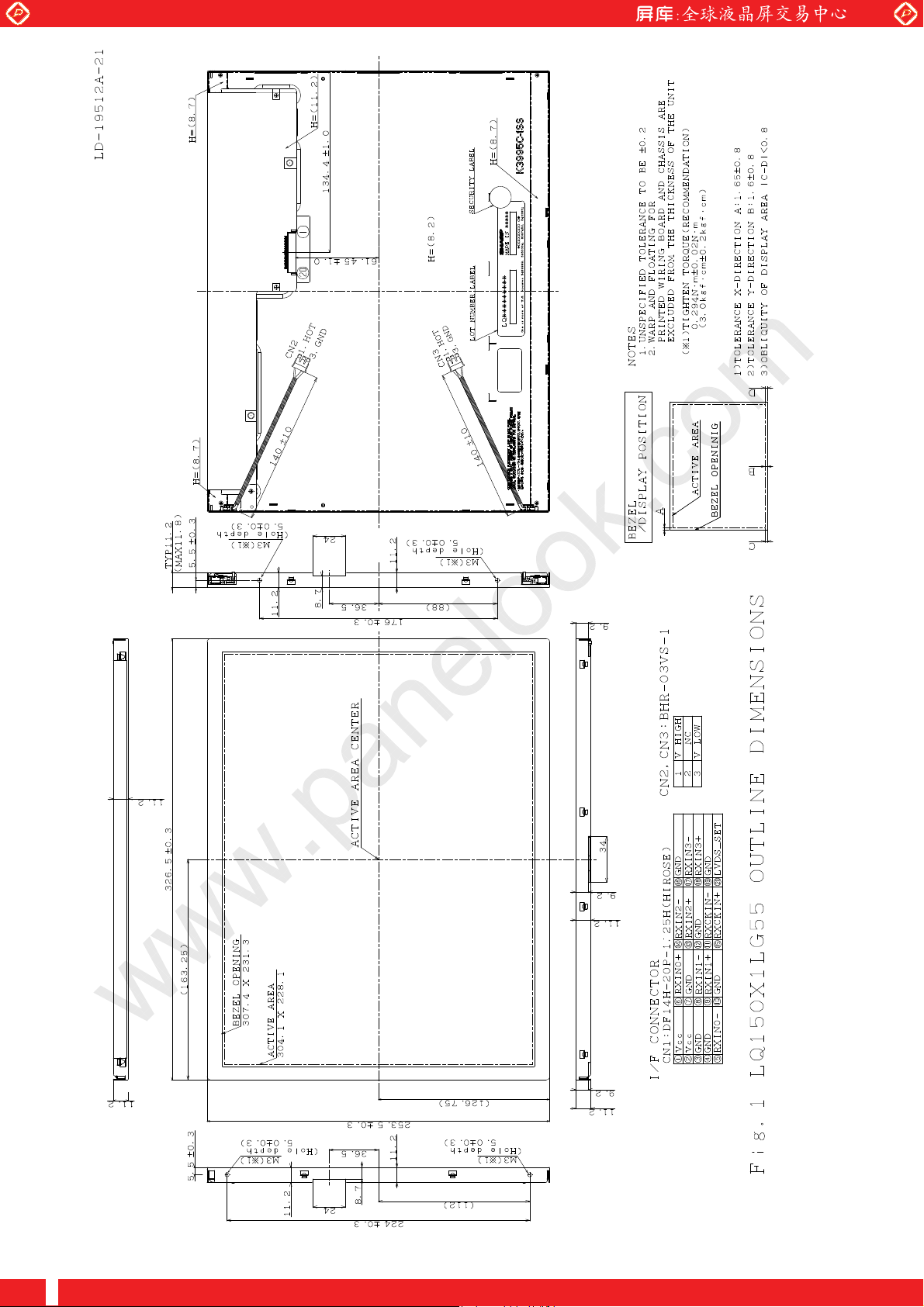
Outline dimensions are shown in Fig.1.
One step solution for LCD / PDP / OLED panel application: Datasheet, inventory and accessory!
www.panelook.com
Page 5
Global LCD Panel Exchange Center
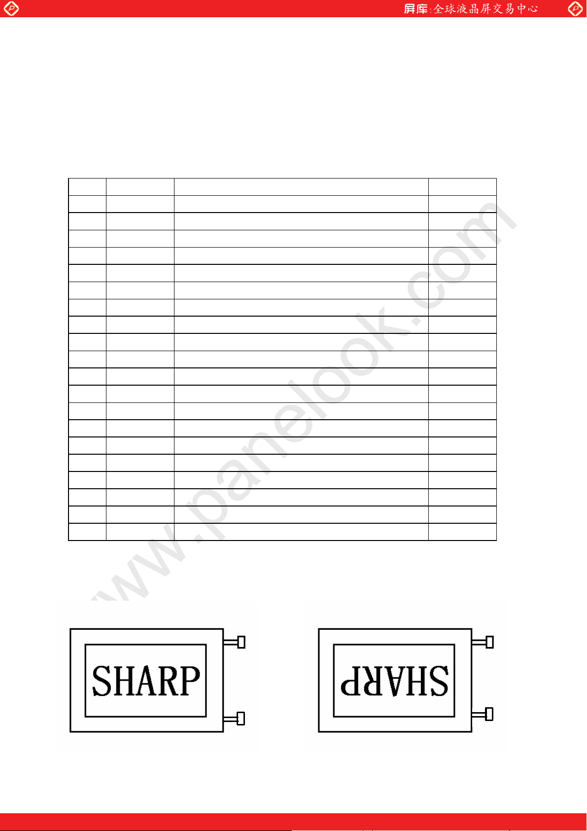
4. Input Terminals
4-1. TFT-LCD panel driving
CN1 (Interface signals and +3.3V DC power supply)
www.panelook.com
LD19512A-3
Using connectors
Corresponding connectors
Pin No. Symbol Function Remark
1 Vcc +3.3V Power supply
2 Vcc +3.3V Power supply
3 GND
4 GND
5 RXIN0- Receiver signal (-) LVDS
6 RXIN0+ Receiver signal (+) LVDS
7 GND
8 RXIN1- Receiver signal (-) LVDS
9 RXIN1+ Receiver signal (+) LVDS
10 GND
11 RXIN2- Receiver signal (-) LVDS
12 RXIN2+ Receiver signal (+) LVDS
DF14H-20P-1.25H (Hirose Electric Co., Ltd.)
:
DF14-20S-1.25C(Hirose Electric Co., Ltd.)
:
(※)
Please do not use it besides corresponding conector
13 GND
14 RXCKIN- Clock signal (-) LVDS
15 RXCKIN+ Clock signal (+) LVDS
16 GND
17 RXIN3- Receiver signal (-) LVDS
18 RXIN3+ Receiver signal (+) LVDS
19 HANTEN Horizontal/Vertical display mode select signal
20 LVDS_SET LVDS_SET
note2
【
】
HANTEN=“ LOW” HANTEN=“ High”
【
【
note2
note1
】
】
One step solution for LCD / PDP / OLED panel application: Datasheet, inventory and accessory!
www.panelook.com
Page 6
Global LCD Panel Exchange Center
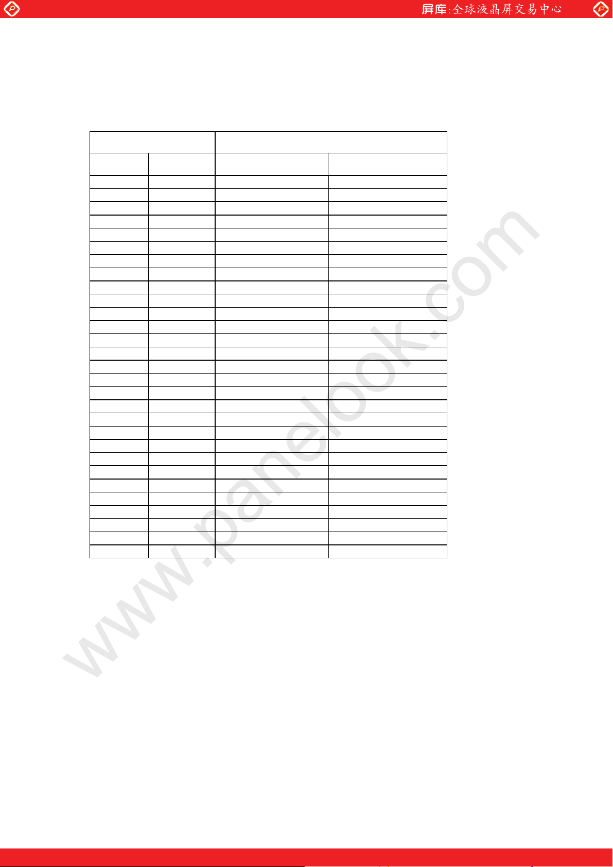
4-2. Data Mapping
1) 8 bit input
note1】pin assignment with LVDS_SET pin (Thine: THC63LVDF83A)
【
Transmitter 20pin LVDS_SET
Pin No Data = H (3.3V) = L (GND) or Open
51 TA0 R2 R0 (LSB)
52 TA1 R3 R1
54 TA2 R4 R2
55 TA3 R5 R3
56 TA4 R6 R4
3 TA5 R7 (MSB) R5
4 TA6 G2 G0 (LSB)
6 TB0 G3 G1
7 TB1 G4 G2
11 TB2 G5 G3
12 TB3 G6 G4
14 TB4 G7 (MSB) G5
15 TB5 B2 B0 (LSB)
19 TB6 B3 B1
20 TC0 B4 B2
22 TC1 B5 B3
23 TC2 B6 B4
24 TC3 B7 (MSB) B5
27 TC4 High or low High or low
28 TC5 High or low High or low
30 TC6 DE DE
50 TD0 R0 (LSB) R6
2 TD1 R1 R7 (MSB)
8 TD2 G0 (LSB) G6
10 TD3 G1 G7 (MSB)
16 TD4 B0 (LSB) B6
18 TD5 B1 B7 (MSB)
25 TD6 (NA) (NA)
31 CLK IN CLK CLK
www.panelook.com
LD19512A-4
One step solution for LCD / PDP / OLED panel application: Datasheet, inventory and accessory!
www.panelook.com
Page 7
Global LCD Panel Exchange Center
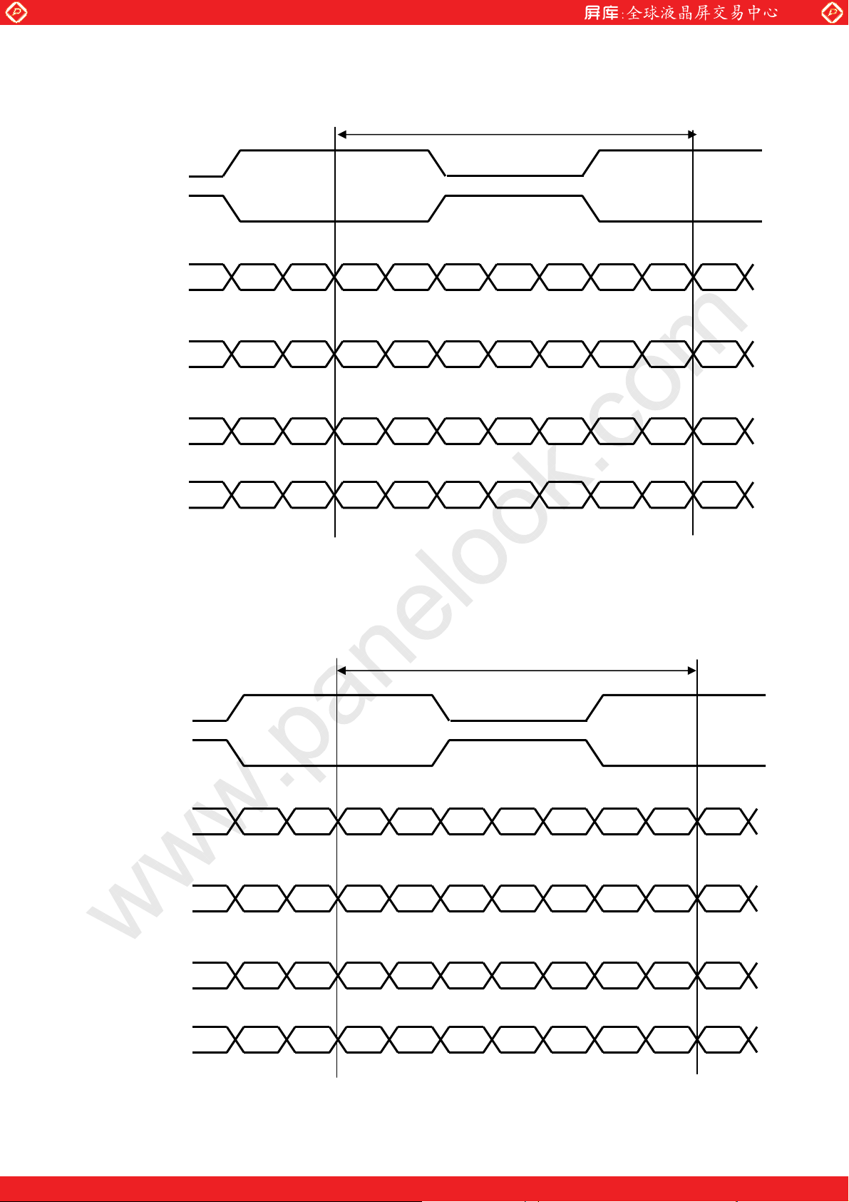
<LVDS_SET=H>
RXCKIN+
RXCKIN-
www.panelook.com
LD19512A-5
1 cycle
RXIN0+
RXIN0-
RXIN1+
RXIN1-
RXIN2+
RXIN2-
RXIN3+
RXIN3-
DE : Display Enable
NA : Not Available
<LVDS_SET = L or Open>
G2 R7 R6 R5 R4 R3 R2 R2R3 G2
B3 B2 G7 G6 G5 G4 G3 G3G4 B3
DE B7 B6 B5 B4 B4B5 DENA NA
NA G1 G0 R1 R0 R0R1 NAB1 B0
1 cycle
RXCXIN+
RXCXIN-
RXIN0+
RXIN0-
RXIN1+
RXIN1-
RXIN2+
RXIN2-
RXIN3+
RXIN3-
DE : Display Enable
NA : Not Available
G0 R5 R4 R3 R2 R1 R0 R0R1 G0
B1 B0 G5 G4 G3 G2 G1 G1G2 B1
DE B5 B4 B3 B2 B2B3 DENA NA
NA G7 G6 R7 R6 R6R7 NAB7 B6
One step solution for LCD / PDP / OLED panel application: Datasheet, inventory and accessory!
www.panelook.com
Page 8
Global LCD Panel Exchange Center
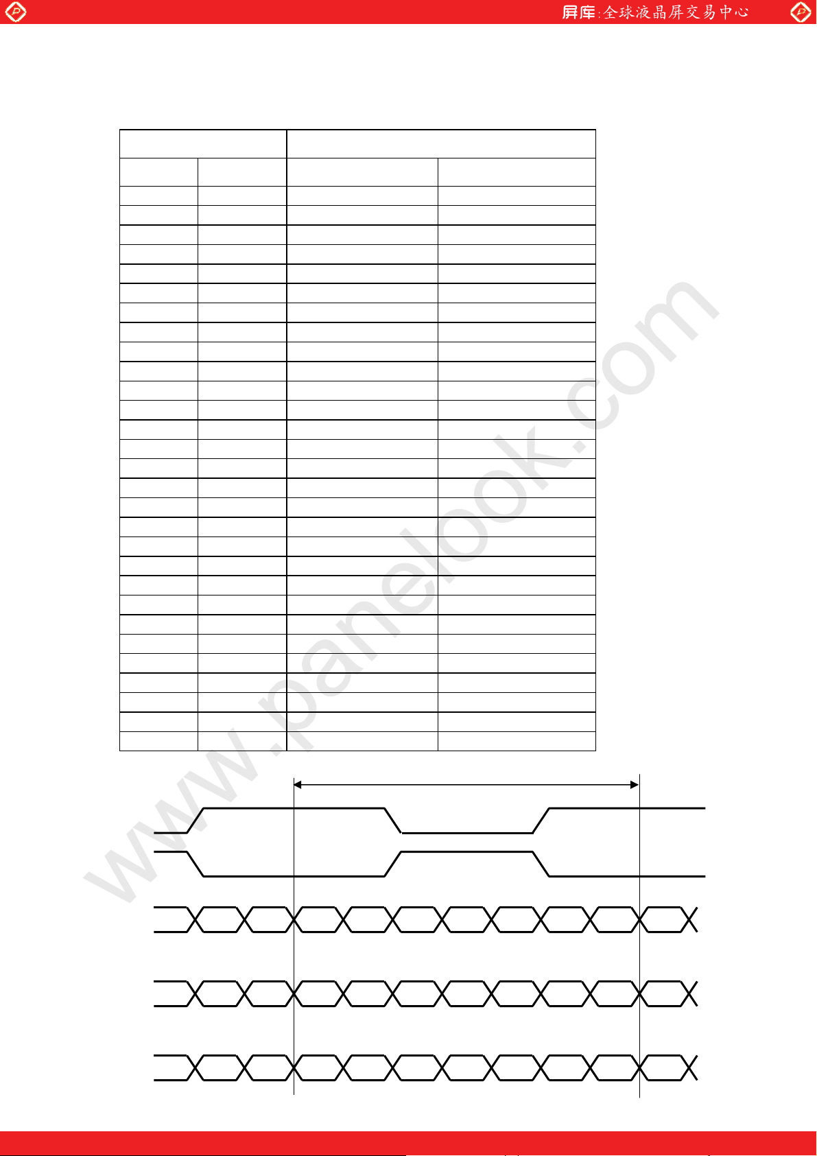
2) 6 bit input
note1】pin assignment with LVDS_SET pin (Thine: THC63LVDF83A)
【
Transmitter 20pin LVDS_SET
Pin No Data = H (3.3V) = L (GND) or Open
51 TA0 R0 (LSB)
52 TA1 R1
54 TA2 R2
55 TA3 R3
56 TA4 R4
3 TA5 R5 (MSB)
4 TA6 G0 (LSB)
6 TB0 G1
7 TB1 G2
11 TB2 G3
12 TB3 G4
14 TB4 G5 (MSB)
15 TB5 B0 (LSB)
19 TB6 B1
20 TC0 B2
22 TC1 B3
23 TC2 B4
24 TC3 B5 (MSB)
27 TC4 High or low
28 TC5 High or low
30 TC6 DE
50 TD0 GND
2 TD1 GND
8 TD2 GND
10 TD3 GND
16 TD4 GND
18 TD5 GND
25 TD6 (NA)
31 ClKIN CLK
www.panelook.com
LD19512A-6
−
−
−
−
−
−
−
−
−
−
−
−
−
−
−
−
−
−
−
−
−
−
−
−
−
−
−
−
−
1 cycle
RXCKIN+
RXCKIN-
RXIN0+
RXIN0-
RXIN1+
RXIN1-
G0 R5 R4 R3 R2 R1 R0 R0R1 G0
B1 B0 G5 G4 G3 G2 G1 G1G2 B1
RXIN2+
RXIN2-
DE B5 B4 B3 B2 B2B3 DENA NA
DE : Display Enable
NA : Not Available
One step solution for LCD / PDP / OLED panel application: Datasheet, inventory and accessory!
www.panelook.com
Page 9
Global LCD Panel Exchange Center
㽲
㽳
t
㽴
R
K
,B7,
R
K
,B1,
R
K
www.panelook.com
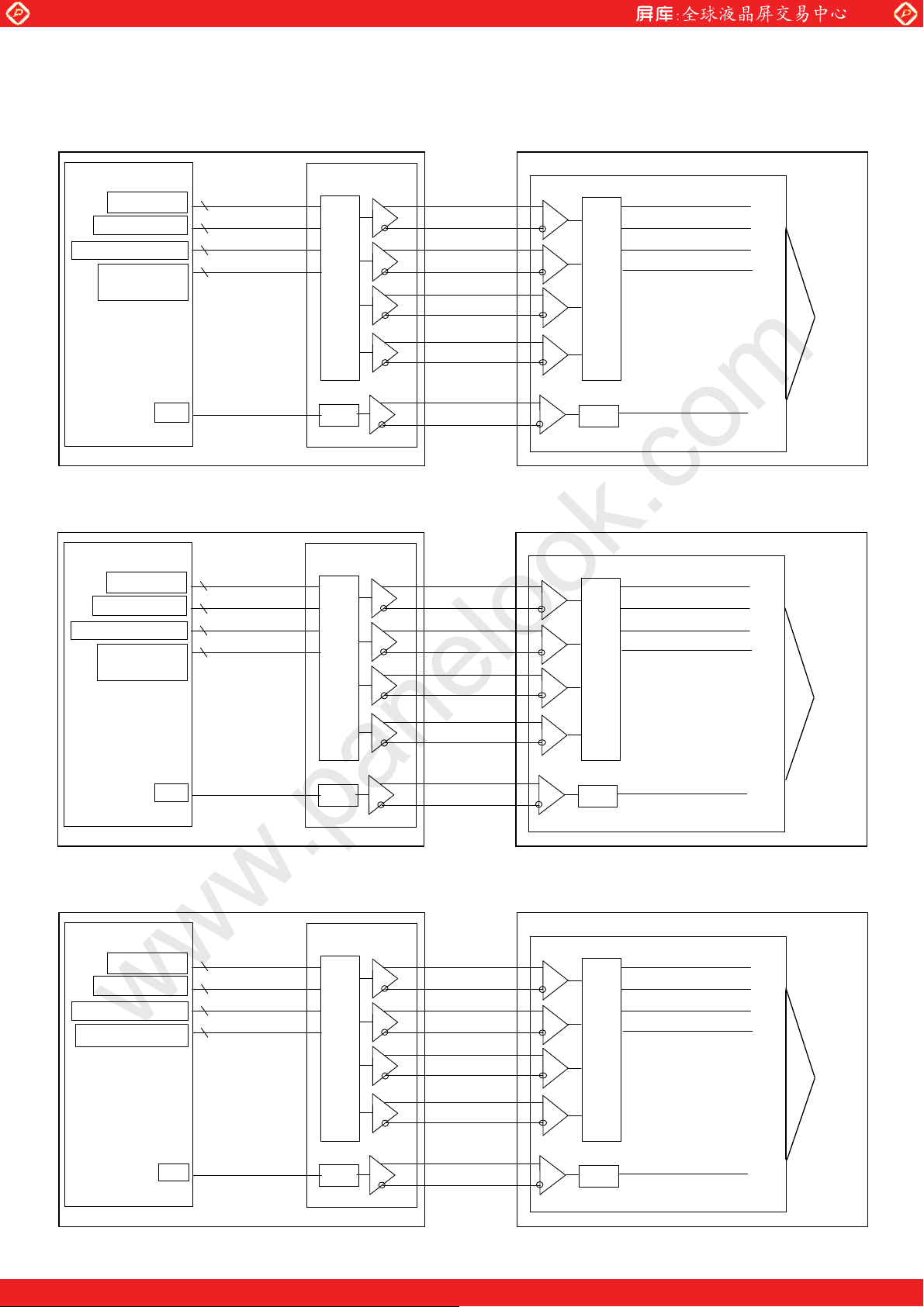
4-3 Interface block diagram LD-19512A-7
(Computer Side)
8Bit䇭Mode
LVDS_SET=L (20 pin=GND or OPEN)
Controller
7
TA 0 - 6
R0-R5,G0
G1-G5,B0,B1
B2-B5, NA,NA,DE
R6,R7,G6,G7,
NA
B6
C
䇭Mode
8Bi
LVDS_SET=H (20 pin=3.3[V])
7
7
7
TB 0 - 6
TC 0 - 6
TD 0 - 6
CLK IN
THC63LVDM83
TTL PARALLEL-TO-LVDS
PLL
RXIN0+(6)
RXIN0-(5)
RXIN1+(9)
RXIN1-(8)
RXIN2+(12)
RXIN2-(11)
RXIN3+(18)
RXIN3-(17)
RXCKIN+(15)
RXCKIN-(14)
(TFT-LCD side)
Single LVDS interface contained in a control
LVDS-TO-PARALLEL TTL
PLL
RA 0 - 6
RB 0 - 6
RC 0 - 6
RD 0 - 6
CK OUT
Internal circuits
Controller
7
R2-R7,G2
G3-G7,B2,B3
B4-B7, NA,NA,DE
7
7
7
R0,R1,G0,G1,
NA
B0
C
6Bit䇭Mode
LVDS_SET=H (20 pin=3.3[V])
Controller
7
R0-R5,G0
G1-G5,B0,B1
B2-B5, NA,NA,DE
ALL NA
7
7
7
TA 0 - 6
TB 0 - 6
TC 0 - 6
TD 0 - 6
CLK IN
TA 0 - 6
TB 0 - 6
TC 0 - 6
TD 0 - 6
THC63LVDM83
TTL PARALLEL-TO-LVDS
PLL
THC63LVDM83
TTL PARALLEL-TO-LVDS
RXIN0+(6)
RXIN0-(5)
RXIN1+(9)
RXIN1-(8)
RXIN2+(12)
RXIN2-(11)
RXIN3+(18)
RXIN3-(17)
RXCKIN+(15)
RXCKIN-(14)
RXIN0+(6)
RXIN0-(5)
RXIN1+(9)
RXIN1-(8)
RXIN2+(12)
RXIN2-(11)
RXIN3+(18)
RXIN3-(17)
Single LVDS interface contained in a control IC
LVDS-TO-PARALLEL TTL
PLL
Single LVDS interface contained in a control IC
LVDS-TO-PARALLEL TTL
RA 0 - 6
RB 0 - 6
RC 0 - 6
RD 0 - 6
CK OUT
RA 0 - 6
RB 0 - 6
RC 0 - 6
RD 0 - 6
Internal circuits
Internal circuits
C
One step solution for LCD / PDP / OLED panel application: Datasheet, inventory and accessory!
CLK IN
PLL
RXCKIN+(15)
RXCKIN-(14)
PLL
CK OUT
www.panelook.com
Page 10
Global LCD Panel Exchange Center
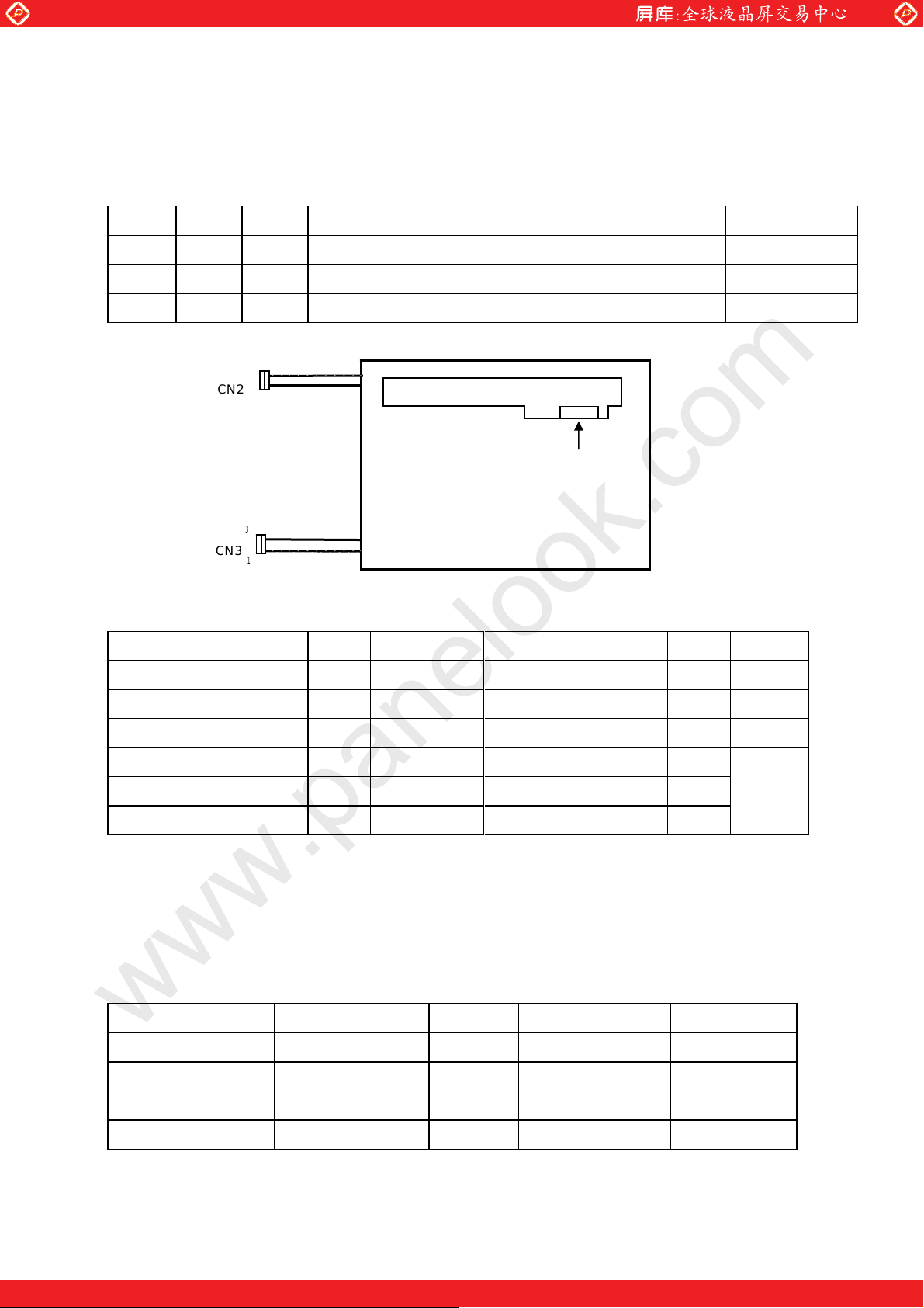
4-4. Backlight
CN 2, 3
www.panelook.com
LD19512A-8
The module-side connector
The user-side connector
BHR-03VS-1 (JST)
:
SM02(8.0)B-BHS-1-TB(LF)(SN) (JST)
:
Pin no. symbol I/O Function Color
1
2 N.C.
3
V
V
HIGH
LOW
CN2
I Power supply for lamp (High voltage side) Pink
−
−
I Power supply for lamp (Low voltage side) White
Pink cable is V
1
White cable is V
3
HIGH
LOW
Signal processing board
CN1
20
1
Insert direction
TFT LCD back view
CN3
White cable is V
3
1
Pink cable is V
LOW
HIGH
5. Absolute Maximum Ratings
Parameter Symbol Condition Ratings Unit Remark
Supply voltage Vcc Ta=25℃ -0.3
Input voltage(LVDS Signal) VI1 Ta=25℃ -0.3
Input voltage(LVDS_SET) VI2 Ta=25℃ -0.3
Storage temperature T
Operating temperature T
STG
Panel surface 0 〜 + 60
OPA
Lamp Voltage VLa
Note1】Humidity:95%RH Max. ( Ta≦40℃ )
【
−
−
+ 4.0
〜
Vcc
〜
Vcc+ 0.3
〜
-25〜 + 60
2000
Maximum wet-bulb temperature at 39℃ or less. ( Ta>40℃ )
No condensation.
6. Recommended operation condition
Parameter
Supply voltage Vcc
Symbol Min. Typ. Max. Unit Remark
+
3.0
+3.3
+
3.6
V
V
V
V
Note1
【
℃
℃
rms
V
Note1
【
】
】
LVDS Signals VL 0 2.4
Input voltage VI 0 Vcc
Surface temperature Topa 0 +60
V
V
℃
【
【
【
Note2
Note3
Note4
One step solution for LCD / PDP / OLED panel application: Datasheet, inventory and accessory!
】
】
】
www.panelook.com
Page 11
Global LCD Panel Exchange Center
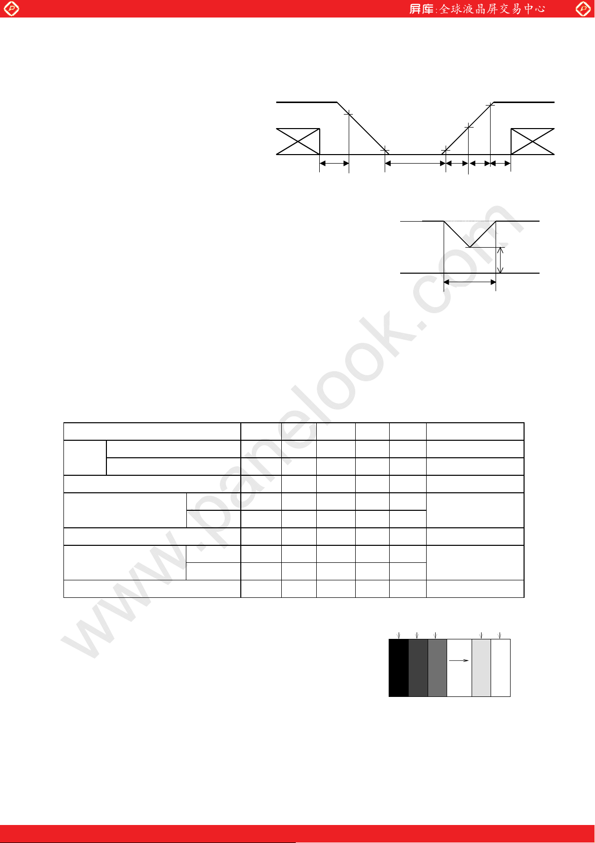
Note1】On-off conditions for supply voltage
【
0<t1≦15ms
0<t2≦10ms
0<t3≦100ms
0<t4≦1s
200ms<t5
Vcc-dip conditions
1) 2.5V≦Vcc
td≦10ms
2) Vcc<2.5V
Vcc-dip conditions should also follow the On-off
conditions for supply voltage
Note2】RXIN0-, RXIN0+,RXIN1-,RXIN1+,RXIN2-,RXIN2+,
【
RXCKIN-,RXCKIN+,RXIN3-,RXIN3+
www.panelook.com
VCC
Signal
T
4
0.9VCC
0.3V
T
VCC
5
0.3V
2.7V
T1
0.9VCC
T
Td
2
LD19512A-9
VCC
Signal
T
3
2.5V
Note3】LVDS_SET
【
Note4】Humidity: 95%RH Max. at Ta=<40
【
Maximum wet-bulb temperature at 39
o
C.
o
C or less at Ta>40 oC.
No condensation.
7. Electrical Characteristics
7-1. TFT-LCD panel driving Ta=25
Parameter Symbol Min. Typ. Max. Unit Remark
Vcc Supply voltage Vcc +3.0 +3.3 +3.6 V
Current dissipation Icc
Permissive input ripple voltage V
Differential input High
Threshold voltage Low
RF
V
TH
V
TL
Input voltage width for LVDS receiver Vi 0
High VIH 2.1
Low V
Terminal resistor
Note1】 V
【
Note2】 Typical current situation : 253-gray-bar pattern
【
: Common mode voltage of LVDS driver.
CM
Vcc=+3.3V, fck=65MHz, Ta=25
℃
IL
R
T
−
−−
−−
–100
−−
−
300 400 mA
100 mVp-p Vcc=+3.3V
+100 mV V
−−
−
2.4 V
−−
mV
V Input voltage
0.8 V
100
−Ω
RGB
GS0
Differential input
RGB
GS1
CM
RGB
GS2
Gray scale : GS(n)
℃
−
Note2
【
=+1.2V
Note1
【
....
GS251
−
−
RGB
】
】
RGB
GS252
One step solution for LCD / PDP / OLED panel application: Datasheet, inventory and accessory!
www.panelook.com
Page 12
Global LCD Panel Exchange Center
r
7-2. Backlight
The back light system is an edge-lighting type with 2 CCFTs (Cold Cathode Fluorescent Tube).
The characteristics of the lamp are shown in the following table.
The value mentioned below is at the case of one CCFT.
Parameter Symbol Min. Typ. Max. Unit Remark
Lamp current range IL 3.5 6.5 7.0 mArms
Lamp voltage V
Lamp power consumption P
Lamp frequency FL 40 55 70 kHz
Kick-off voltage Vs
Life time
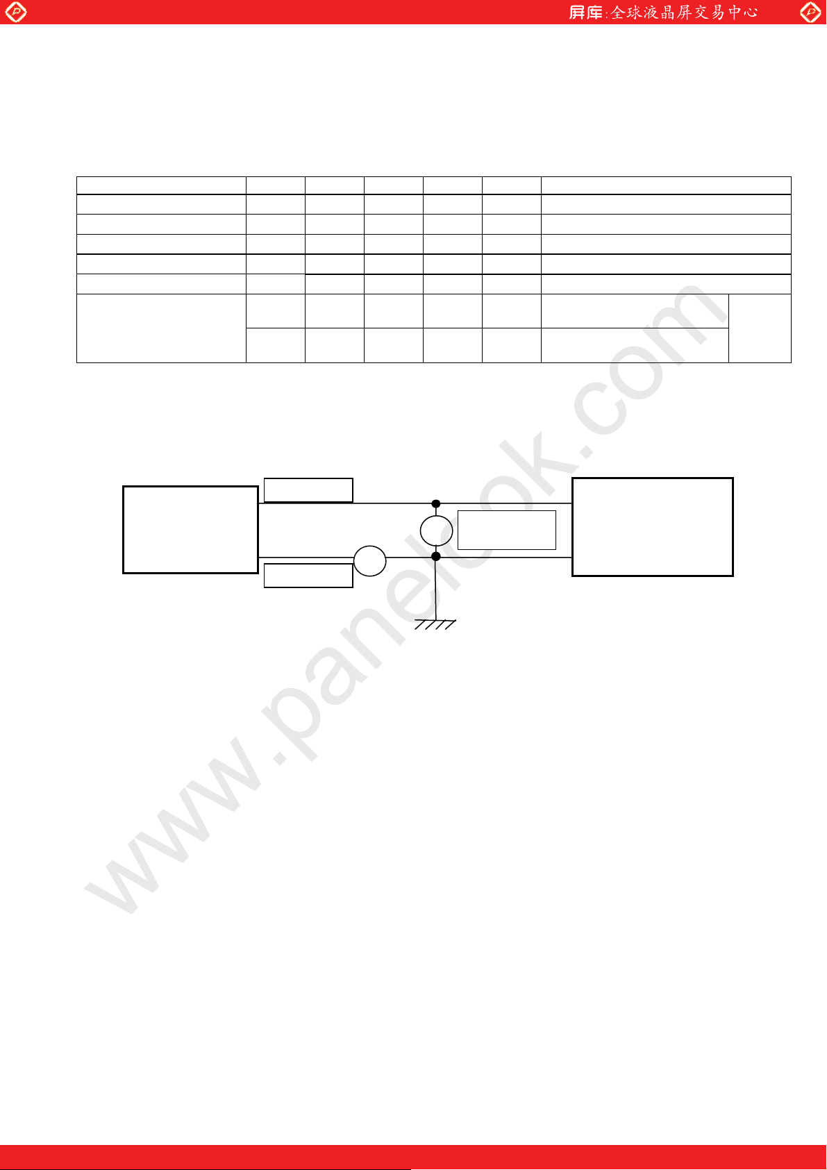
Note1】A lamp can be light in the range of lamp current shown above.
【
TL 50,000
Maximum rating for current is measured by high frequency current measurement equipment
connected to V
at circuit showed below.
LOW
(Note : To keep enough kick-off voltage and necessary steady voltage for CCFT.)
Panel surface temperature : 0〜60
www.panelook.com
LD19512A-10
Note1
【
L
L
−
−
660
4.3
−
−
Vrms
W
I
【
【
−−
−−
1400 Vrms
hour Lamp (When not mounted
Inverter output
into LCD module.
−
(25,000)
−
hour When mounted into LCD
module (Reference value)
℃
】
=6.5 mArms Ta=25℃ 60kHz
L
Note2
】
Note3
】
Note4】Ta=0
【
℃
【
Note5
】
CN2,3䋺1pin
L
V
〜
×
Inverter
) .
V
L
Module
A
CN2,3䋺3pin
Note2】Referential data per one CCFT by calculation ( I
【
The data don’t include loss at inverter. (I
Note3】Lamp frequency of inverter may produce interference with horizontal synchronous frequency, and this
【
〜
=6.0 mArms)
L
Inverte
may cause horizontal beat on the display. Therefore, adjust lamp frequency, and keep inverter as far as
from module or use electronic shielding between inverter and module to avoid interference.
Note4】The open output voltage of the inverter shall be maintained for more than 1s; otherwise
【
the lamp may not be turned on.
Note5】Above value is applicable when lamp (the long side of LCD module) is placed horizontally.
【
(Landscape position)
Lamp life time is defined that it applied either ① or ② under this condition
(Continuous turning on at Ta=25
o
C, IL=6.5mArms)
① Brightness becomes 50% of the original value under standard condition.
② Kick-off voltage at Ta=0
o
C exceeds maximum value, (1,400)Vrms.
(Lamp life time may vary if lamp is in portrait position due to the change of mercury density inside
the lamp.)
Lamp life time shortens according to the used state and environment.
In case of operating under lower temp environment, the lamp exhaustion is accelerated
and the brightness becomes lower.(Continuous operating for around 1 month under lower temp
condition may reduce the brightness to half of the original brightness.)
The life of a lamp is accelerated when using it in the environment where a lamp cannot get warm easily.
When using it outdoors and ON/OFF is repeated frequently
(
)
In case of such usage under lower temp environment, periodical lamp check and exchange is
recommended.
One step solution for LCD / PDP / OLED panel application: Datasheet, inventory and accessory!
www.panelook.com
Page 13
Global LCD Panel Exchange Center
Note6】The performance of the backlight, for example life time or brightness, is much influenced
【
by the characteristics of the DC-AC inverter for the lamp. When you design or order the
inverter, please make sure that a poor lighting caused by the mismatch of the backlight and
the inverter (miss-lighting,flicker, etc.) never occur. when you confirm it, the module should
be operated in the same condition as it is installed in your instrument.
Be sure to use a back light power supply with the safety protection circuit such as the detection circuit
for the excess voltage, excess current and or electric discharge waveform.
Be sure to use the detect circuit by which one side of the CCFT lamps can be controlled
independently. Otherwise, when one side of the CCFT is open, the excess current may possibly
be applied to the other side of the lamp.
Note7】It is required to have the inverter designed so that to allow the impedance deviation of the two CCFT
【
lamps and the capacity deviation of barast capacitor.
Note8】Under the environment of 10 lx or less, miss-lighting delay may occur.
【
【Note9】
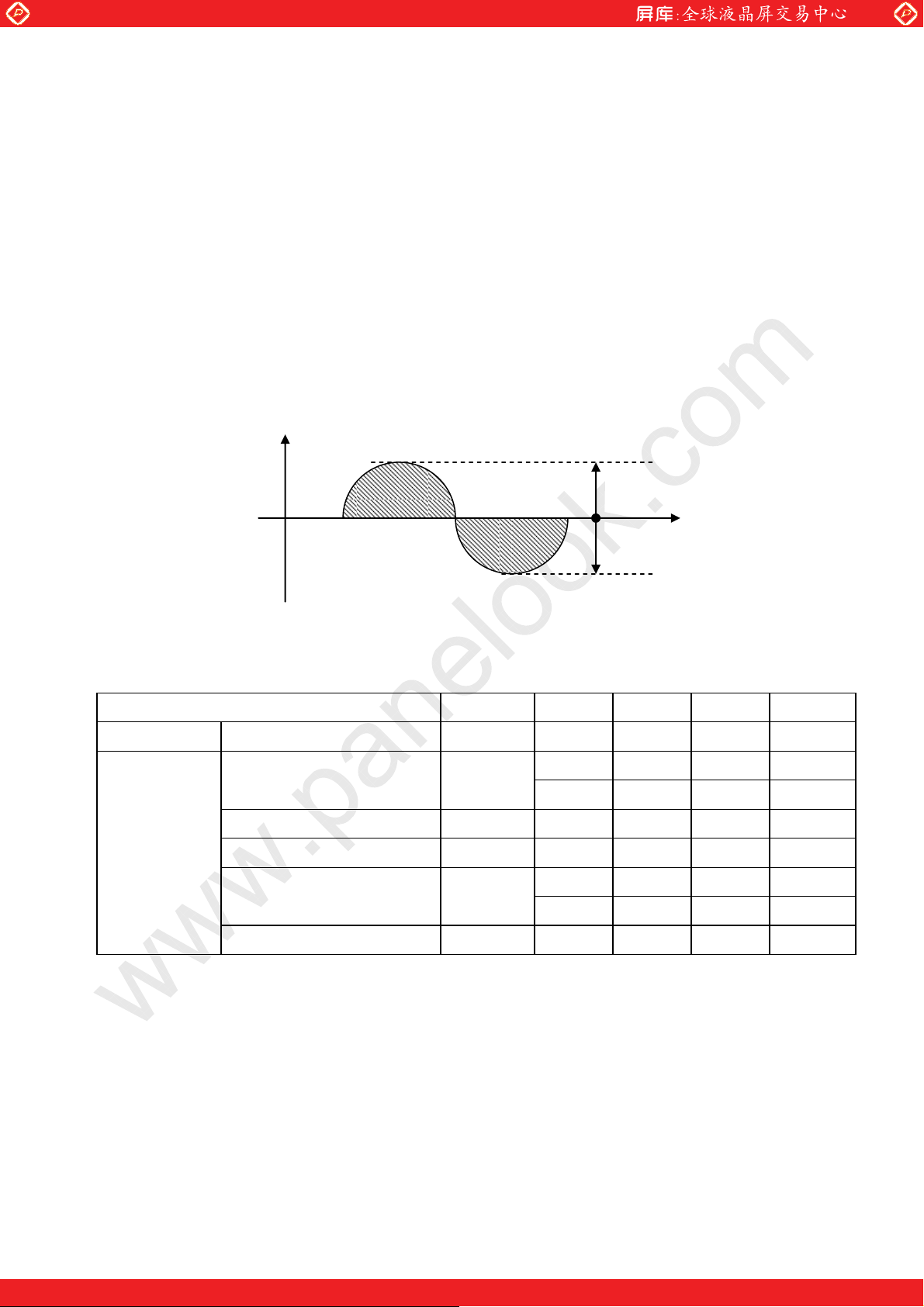
Wave efficiency: 1.20 ≦ Ip(P) / Irms or Ip(N) / Irms ≦ 1.63
Imbalanced value: 0.95
A lamp waveform should satisfy the following conditions.
www.panelook.com
Ip(P) / Ip (N) ≦ 1.05
≦
LD19512A-11
p(P)
I
Ip(N)
8. Timing characteristics of input signals
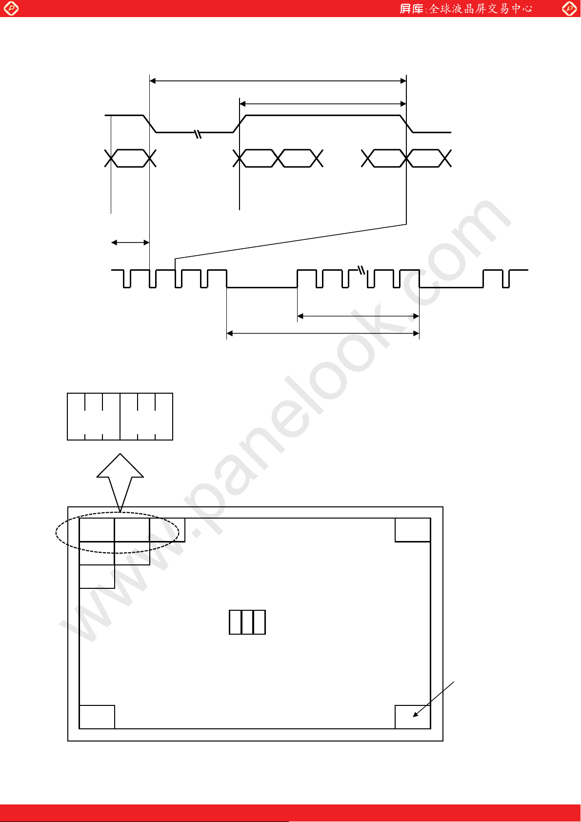
8-1. Timing characteristics
Parameter Symbol Min. Typ. Max. Unit
Clock signal Frequency 1/Tc 50.0 65.0 80.0 MHz
ENAB signal
Horizontal period (High) THd 1024 1024 1024 clock
Vertical Frequency fv 54 60 77 Hz
1056 1344 1720 clock Horizontal period TH
16.0 20.7 23.4 μs
773 806 990 line Vertical period TV
12.98 16.66 18.51 ms
Vertical period (High) TVd 768 768 768 line
Note】 In case of using the long vertical period, the deterioration of display quality, flicker etc. may occur.
【
One step solution for LCD / PDP / OLED panel application: Datasheet, inventory and accessory!
www.panelook.com
Page 14
Global LCD Panel Exchange Center
www.panelook.com
LD19512A-12
DE
DATA
(R,G,B)
DE
1024
Tc
TH
THd
1 2
12
TV
1024
768767
TVd
8-2. Input Data Signals and Display Position on the screen
R1 G1 B1 R2 G2 B2
(1、1) (1,2)
1・1 1・2 1・3
2・1 2・2
3・1
R G B
1・1024
768・1024
768・1
Display Position of Data (V,H)
One step solution for LCD / PDP / OLED panel application: Datasheet, inventory and accessory!
www.panelook.com
Page 15
Global LCD Panel Exchange Center
9. Input Signals, Basic Display Colors and Gray Scale of Each Color
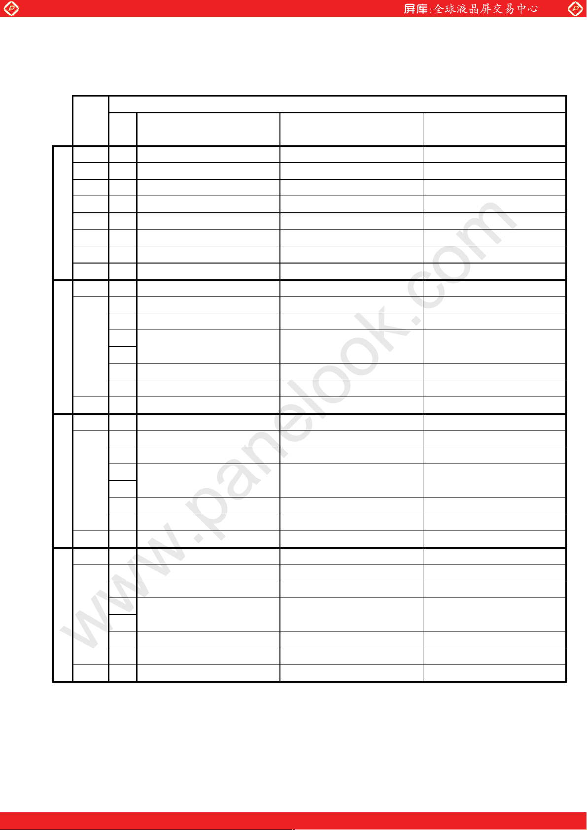
9-1. 8bit input
Colors & Gray
Gray scale Scale
R0 R1 R2 R3 R4 R5 R6 R7 G0 G1 G2 G3 G4 G5 G6 G7 B0 B1 B2 B3 B4 B5 B6 B7
www.panelook.com
LD19512A-13
Data signal
Black
Blue
Basic Color Gray Scale of Red Gray Scale of Green Gray Scale of Blue
Green
Cyan
Red
Magenta
Yellow
White
Black GS0 0 0 0 0 0 0 0 0 0 0 0 0 0 0 0 0 0 0 0 0 0 0 0 0
×
Darker GS2 0 1 0 0 0 0 0 0 0 0 0 0 0 0 0 0 0 0 0 0 0 0 0 0
×È È È È
ØÈ È È È
Brighter GS250 0 1 0 1 1 1 1 1 0 0 0 0 0 0 0 0 0 0 0 0 0 0 0 0
Ø
GS251 1 1 0 1 1 1 1 1 0 0 0 0 0 0 0 0 0 0 0 0 0 0 0 0
Red GS252 X X 1 1 1 1 1 1 0 0 0 0 0 0 0 0 0 0 0 0 0 0 0 0
Black GS0 0 0 0 0 0 0 0 0 0 0 0 0 0 0 0 0 0 0 0 0 0 0 0 0
×
Darker GS2 0 0 0 0 0 0 0 0 0 1 0 0 0 0 0 0 0 0 0 0 0 0 0 0
×È È È È
ØÈ È È È
0 0 0 0 0 0 0 0 0 0 0 0 0 0 0 0 0 0 0 0 0 0 0 0
−
0 0 0 0 0 0 0 0 0 0 0 0 0 0 0 0 1 1 1 1 1 1 1 1
−
0 0 0 0 0 0 0 0 1 1 1 1 1 1 1 1 0 0 0 0 0 0 0 0
−
0 0 0 0 0 0 0 0 1 1 1 1 1 1 1 1 1 1 1 1 1 1 1 1
−
1 1 1 1 1 1 1 1 0 0 0 0 0 0 0 0 0 0 0 0 0 0 0 0
−
1 1 1 1 1 1 1 1 0 0 0 0 0 0 0 0 1 1 1 1 1 1 1 1
−
1 1 1 1 1 1 1 1 1 1 1 1 1 1 1 1 0 0 0 0 0 0 0 0
−
1 1 1 1 1 1 1 1 1 1 1 1 1 1 1 1 1 1 1 1 1 1 1 1
−
GS1 1 0 0 0 0 0 0 0 0 0 0 0 0 0 0 0 0 0 0 0 0 0 0 0
GS1 0 0 0 0 0 0 0 0 1 0 0 0 0 0 0 0 0 0 0 0 0 0 0 0
Brighter GS250 0 0 0 0 0 0 0 0 0 1 0 1 1 1 1 1 0 0 0 0 0 0 0 0
Ø
GS251 0 0 0 0 0 0 0 0 1 1 0 1 1 1 1 1 0 0 0 0 0 0 0 0
Green GS252 0 0 0 0 0 0 0 0 X X 1 1 1 1 1 1 0 0 0 0 0 0 0 0
Black GS0 0 0 0 0 0 0 0 0 0 0 0 0 0 0 0 0 0 0 0 0 0 0 0 0
×
GS1 0 0 0 0 0 0 0 0 0 0 0 0 0 0 0 0 1 0 0 0 0 0 0 0
Darker GS2 0 0 0 0 0 0 0 0 0 0 0 0 0 0 0 0 0 1 0 0 0 0 0 0
×È È È È
ØÈ È È È
Brighter GS250 0 0 0 0 0 0 0 0 0 0 0 0 0 0 0 0 0 1 0 1 1 1 1 1
Ø
GS251 0 0 0 0 0 0 0 0 0 0 0 0 0 0 0 0 1 1 0 1 1 1 1 1
Blue GS252 0 0 0 0 0 0 0 0 0 0 0 0 0 0 0 0 X X 1 1 1 1 1 1
0 : Low level voltage, 1 : High level voltage.
X :Don’t care
Each basic color can be displayed in 253 gray scales from 8 bit data signals. According to the combination of
total 24 bit data signals, the 16-million-color display can be achieved on the screen.
One step solution for LCD / PDP / OLED panel application: Datasheet, inventory and accessory!
www.panelook.com
Page 16
Global LCD Panel Exchange Center
9-2. 6bit input
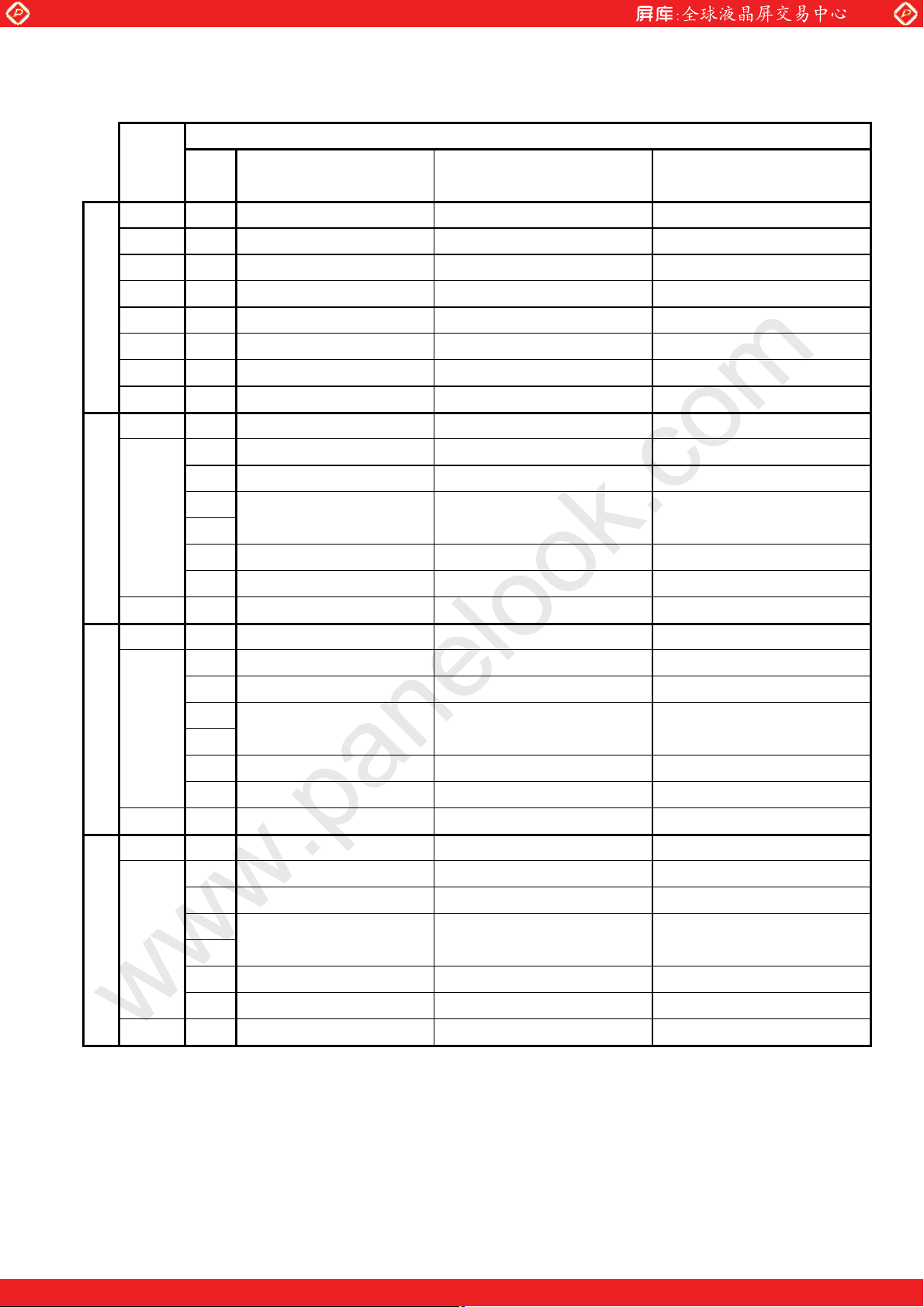
Colors & Gray
Gray scale Scale
R0 R1 R2 R3 R4 R5 G0 G1 G2 G3 G4 G5 B0 B1 B2 B3 B4 B5
www.panelook.com
LD19512A-14
Data signal
Black
Blue
Basic Color Gray Scale of Red Gray Scale of Green Gray Scale of Blue
Green
Cyan
Red
Magenta
Yellow
White
Black GS0 0 0 0 0 0 0 0 0 0 0 0 0 0 0 0 0 0 0
×
Darker GS2 0 1 0 0 0 0 0 0 0 0 0 0 0 0 0 0 0 0
×È È È È
ØÈ È È È
Brighter GS61 1 0 1 1 1 1 0 0 0 0 0 0 0 0 0 0 0 0
Ø
Red GS63 1 1 1 1 1 1 0 0 0 0 0 0 0 0 0 0 0 0
Black GS0 0 0 0 0 0 0 0 0 0 0 0 0 0 0 0 0 0 0
×
Darker GS2 0 0 0 0 0 0 0 1 0 0 0 0 0 0 0 0 0 0
×È È È È
ØÈ È È È
GS1 1 0 0 0 0 0 0 0 0 0 0 0 0 0 0 0 0 0
GS62 0 1 1 1 1 1 0 0 0 0 0 0 0 0 0 0 0 0
GS1 0 0 0 0 0 0 1 0 0 0 0 0 0 0 0 0 0 0
0 0 0 0 0 0 0 0 0 0 0 0 0 0 0 0 0 0
−
0 0 0 0 0 0 0 0 0 0 0 0 1 1 1 1 1 1
−
0 0 0 0 0 0 1 1 1 1 1 1 0 0 0 0 0 0
−
0 0 0 0 0 0 1 1 1 1 1 1 1 1 1 1 1 1
−
1 1 1 1 1 1 0 0 0 0 0 0 0 0 0 0 0 0
−
1 1 1 1 1 1 0 0 0 0 0 0 1 1 1 1 1 1
−
1 1 1 1 1 1 1 1 1 1 1 1 0 0 0 0 0 0
−
1 1 1 1 1 1 1 1 1 1 1 1 1 1 1 1 1 1
−
Brighter GS61 0 0 0 0 0 0 1 0 1 1 1 1 0 0 0 0 0 0
Ø
Green GS63 0 0 0 0 0 0 1 1 1 1 1 1 0 0 0 0 0 0
Black GS0 0 0 0 0 0 0 0 0 0 0 0 0 0 0 0 0 0 0
×
Darker GS2 0 0 0 0 0 0 0 0 0 0 0 0 0 1 0 0 0 0
×È È È È
ØÈ È È È
Brighter GS61 0 0 0 0 0 0 0 0 0 0 0 0 1 0 1 1 1 1
Ø
Blue GS63 0 0 0 0 0 0 0 0 0 0 0 0 1 1 1 1 1 1
GS62 0 0 0 0 0 0 0 1 1 1 1 1 0 0 0 0 0 0
GS1 0 0 0 0 0 0 0 0 0 0 0 0 1 0 0 0 0 0
GS62 0 0 0 0 0 0 0 0 0 0 0 0 0 1 1 1 1 1
0 : Low level voltage, 1 : High level voltage.
Each basic color can be displayed in 64 gray scales from 6 bit data signals. According to the combination of
total 18 bit data signals, the 262,144-color display can be achieved on the screen.
One step solution for LCD / PDP / OLED panel application: Datasheet, inventory and accessory!
www.panelook.com
Page 17
Global LCD Panel Exchange Center
r
g
)
)
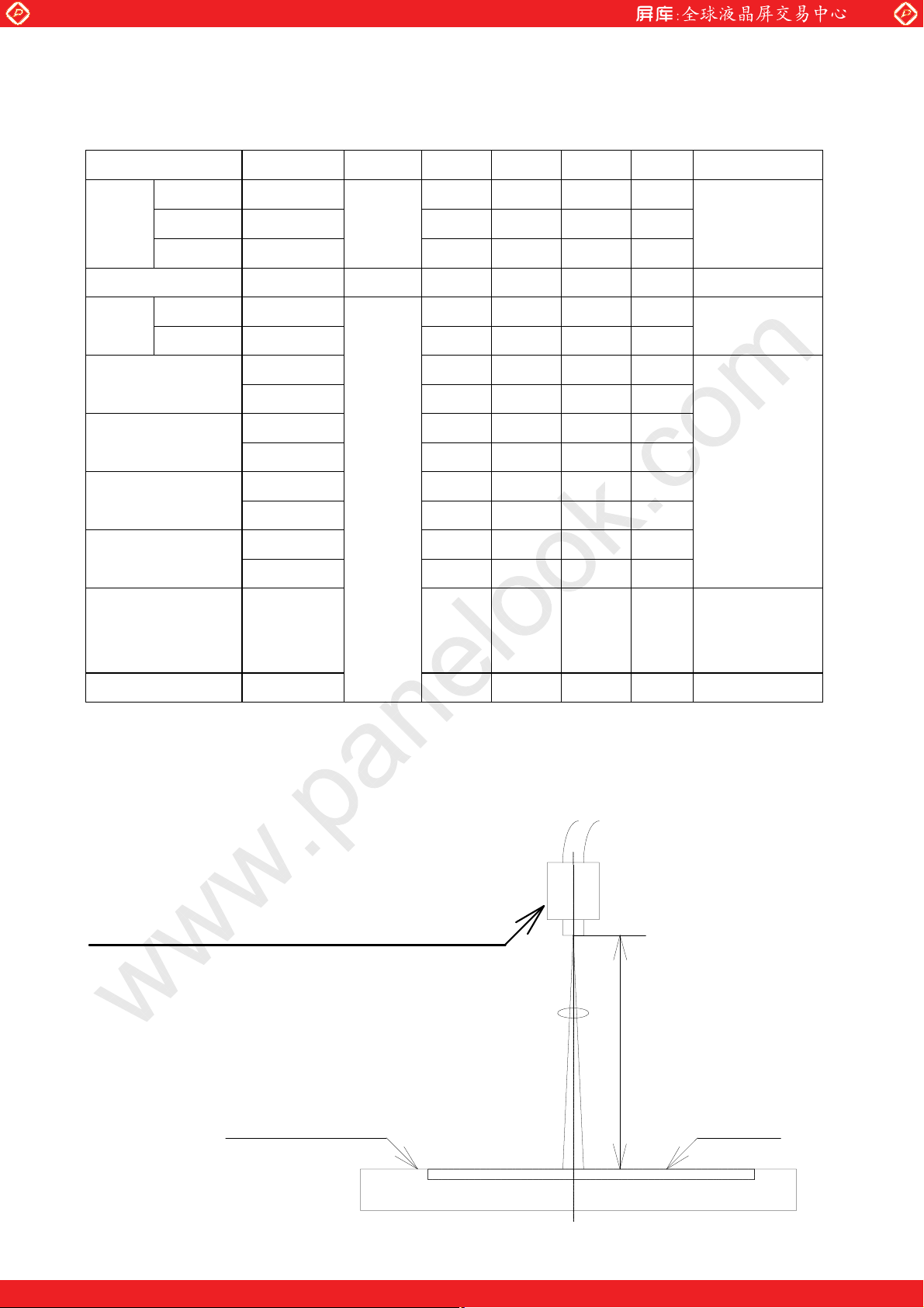
10. Optical Characteristics
www.panelook.com
LD19512A-15
Ta=25
, Vcc =+3.3V
℃
Parameter Symbol Condition Min. Typ. Max. Unit Remark
Viewing
Vertical
angle
range
Horizontal
Contrast ratio
Response Rise
Time Fall
Chromaticity of
White
Chromaticity of
Red
Chromaticity of
Green
Chromaticity of
Blue
Luminance of white Y
θ
θ
21,θ22
θ
CR
τ
τ
11
12
r
d
x
y
x
y
x
y
x
y
L
CR≧10
θ=0°
θ=0°
30 45
45 55
50 60
400 550
−
−
2
6
−
−
−
−
−
−
0.283 0.313 0.343
0.299 0.329 0.359
0.567 0.597 0.627
0.297 0.327 0.357
0.292 0.322 0.352
0.525 0.555 0.585
0.123 0.153 0.183
0.103 0.133 0.163
280 350
−
Deg.
Note1,4
【
Deg.
Deg.
Note2,4
【
ms
Note3,4
【
ms
Note4
【
2
cd/m
IL=6.5mA rms
】
】
】
】
f
=60kHz
L
Note4
White Uniformity
The measurement shall be executed 30 minutes after
※
δ
w
−−
ghting at rating.
li
1.25
【
【
Note5
】
】
The optical characteristics shall be measured in a dark room or equivalent state with the method shown
in Fig.2 below.
Photodetecto
Viewin
Contrast ratio/Luminance of white/Chromaticity : SR-3(TOPCON
angle/Response time : BM-5A (TOPCON
Field
=1°
400mm
TFT-LCD module
Center of the screen
LCD panel
Fig.3 Optical characteristics measurement method
One step solution for LCD / PDP / OLED panel application: Datasheet, inventory and accessory!
www.panelook.com
Page 18
Global LCD Panel Exchange Center
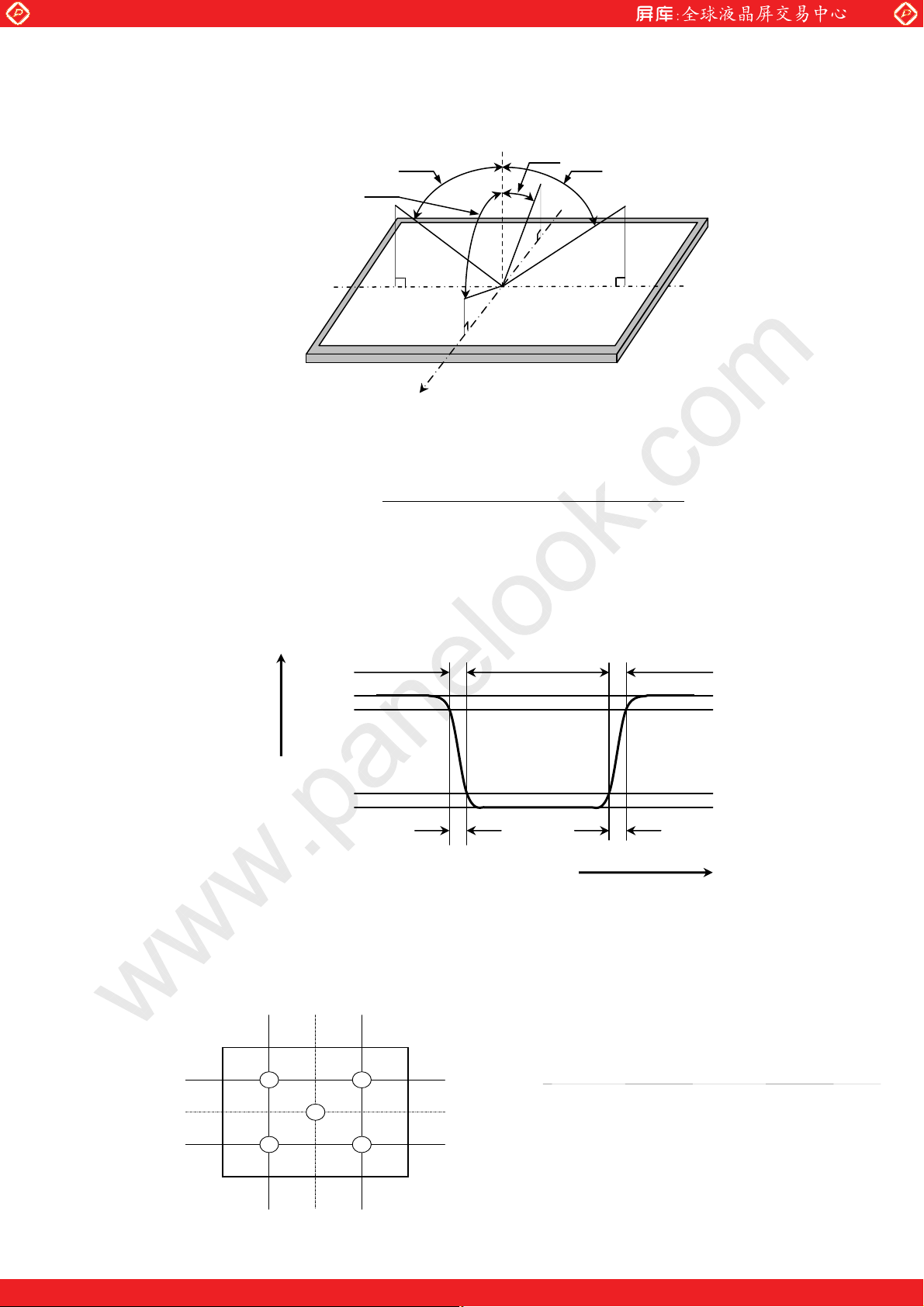
Note1】Definitions of viewing angle range:
【
Note2】Definition of contrast ratio:
【
The contrast ratio is defined as the following.
www.panelook.com
T
22
T
12
’
LD19512A-16
T
11
T
21
Contrast Ratio (CR)
=
Luminance (brightness) with all pixels black
Luminance (brightness) with all pixels white
Note3】Definition of response time:
【
The response time is defined as the following figure and shall be measured by switching the input
signal for "black" and "white".
White white black
100%
90%
Photodetector Output
Note4】This shall be measured at center of the screen.
【
10%
(Relative Value)
0%
W
r
time
W
d
Note5】Definition of white uniformity:
【
White uniformity is defined as the following with five measurements (A〜E).
pixel768 256 512
A
B
D
C
E
192
384
576
pixel
δw=
Maximum Luminance of five points (brightness)
Minimum Luminance of five points (brightness)
One step solution for LCD / PDP / OLED panel application: Datasheet, inventory and accessory!
www.panelook.com
Page 19
Global LCD Panel Exchange Center
11. Handling Precautions
a) Be sure to turn off the power supply when inserting or disconnecting the cable.
b) Be sure to design the cabinet so that the module can be installed without any extra stress such as
warp or twist.
c) Since the front polarizer is easily damaged, pay attention not to scratch it.
www.panelook.com
LD19512A-17
Blow away dust on the polarizer with antistatic 䌎
is sensitive.
It is recommended to peel off softly using the adhesive tape when soil or finger oil is stuck to the polarizer.
When unavoidable, wipe off carefully with a cloth for wiping lenses.
d) Wipe off water drop immediately. Long contact with water may cause discoloration or spots.
e) When the panel surface is soiled, wipe it with absorbent cotton or other soft cloth.
f) Since the panel is made of glass, it may break or crack if dropped or bumped on hard surface.
Handle with care.
g) Since CMOS LSI is used in this module, take care of static electricity and injure the human earth
when handling.Observe all other precautionary requirements in handling components.
h) Since there is a circuit board in the module back, stress is not added at the time of a design assembly.
Please make it like. If stress is added, there is a possibility that circuit parts may be damaged.
i) Protection film is attached to the module surface to prevent it from being scratched .
Peel the film off slowly , just before the use, with strict attention to electrostatic charges.
Blow off 'dust' on the polarizer by using an ionized nitrogen.
j) The polarizer surface on the panel is treated with Anti-Glare for low reflection. In case of attaching
protective board over the LCD, be careful about the optical interface fringe etc. which degrades
display quality.
k) Do not expose the LCD panel to direct sunlight. Lightproof shade etc. should be attached when LCD
panel is used under such environmentl
l) Connect GND to 4 place of mounting holes to stabilize against EMI and external noise.
m) There are high voltage portions on the backlight and very dangerous. Careless touch may lead to
electrical shock. When exchange lamps or service, turn off the power without tail.
n) When handling LCD modules and assembling them into cabinets, please be noted that long-term
storage in the environment of oxidization or deoxidization gas and the use of such materials as
reagent,solvent, adhesive, resin, etc. which generate these gasses, may cause corrosion and
discoloration of the LCD modules.
o) Cold cathode fluorescent lamp in LCD panel contains a small amount of mercury, please follow local
ordinances or regulations for disposal.
p) Be careful of a back light lead not to pull by force at the time of the wiring to an inverter,
or line processing.
blow. It is undesirable to wipe off because a polarizer
2
q) When install LCD modules in the cabinet, please tighten with “torque=0.294±0.02N・m(3.0±0.2kgf・cm)”.
Be sure to confirm it in the same condition as it is installed in your instrument.
r) Liquid crystal contained in the panel may leak if the LCD is broken. Rinse it as soon as possible if it gets
inside your eye or mouth by mistake.
s) Notice:Never dismantle the module , because it will cause failure.
Please don't remove the fixed tape, insulateing tape etc that was pasted on the original module.
(except for protection film of the panel and the crepe tape(yellow tape) of fixing lamp
cable temporarily.)
One step solution for LCD / PDP / OLED panel application: Datasheet, inventory and accessory!
www.panelook.com
Page 20
Global LCD Panel Exchange Center
t) Be careful when using it for long time with fixed pattern display as it may cause afterimage.
䋨Please use a screen saver etc., in order to avoid an afterimage.䋩
u) Adjusting volume have been set optimally before shipment, so do not change any adjusted value.
If adjusted value is changed, the specification may not be satisfied.
v) If a minute particle enters in the module and adheres to an optical material, it may cause display
non-uniformity issue, etc. Therefore, fine-pitch filters have to be installed to cooling and inhalation hole if
you intend to install a fan.
w)The lamp used for this product is very sensitive to the temperature.
Luminance decreases rapidly when it is used for a long time or repeatedly under the environment of the
low temperature or the module is being cooled.
Please avoid the continuous or repeating use of it under such an environment.
It may decrease up to 50% of the initial luminance in about one month under the low temperature
environment.
Please consult our company when it is used under the environment like the above mentioned.
x) In case of operating under lower temp environment, the lamp exhaustion is accelerated
and the brightness becomes lower.(Continuous operating for around 1 month under lower temp
condition may reduce the brightness to half of the original brightness.)
The life of a lamp is accelerated when using it in the environment where a lamp cannot get warm easily.
When using it outdoors and ON/OFF is repeated frequently
(
In case of such usage under lower temp environment, periodical lamp check and exchange is
recommended.
www.panelook.com
LD19512A-18
)
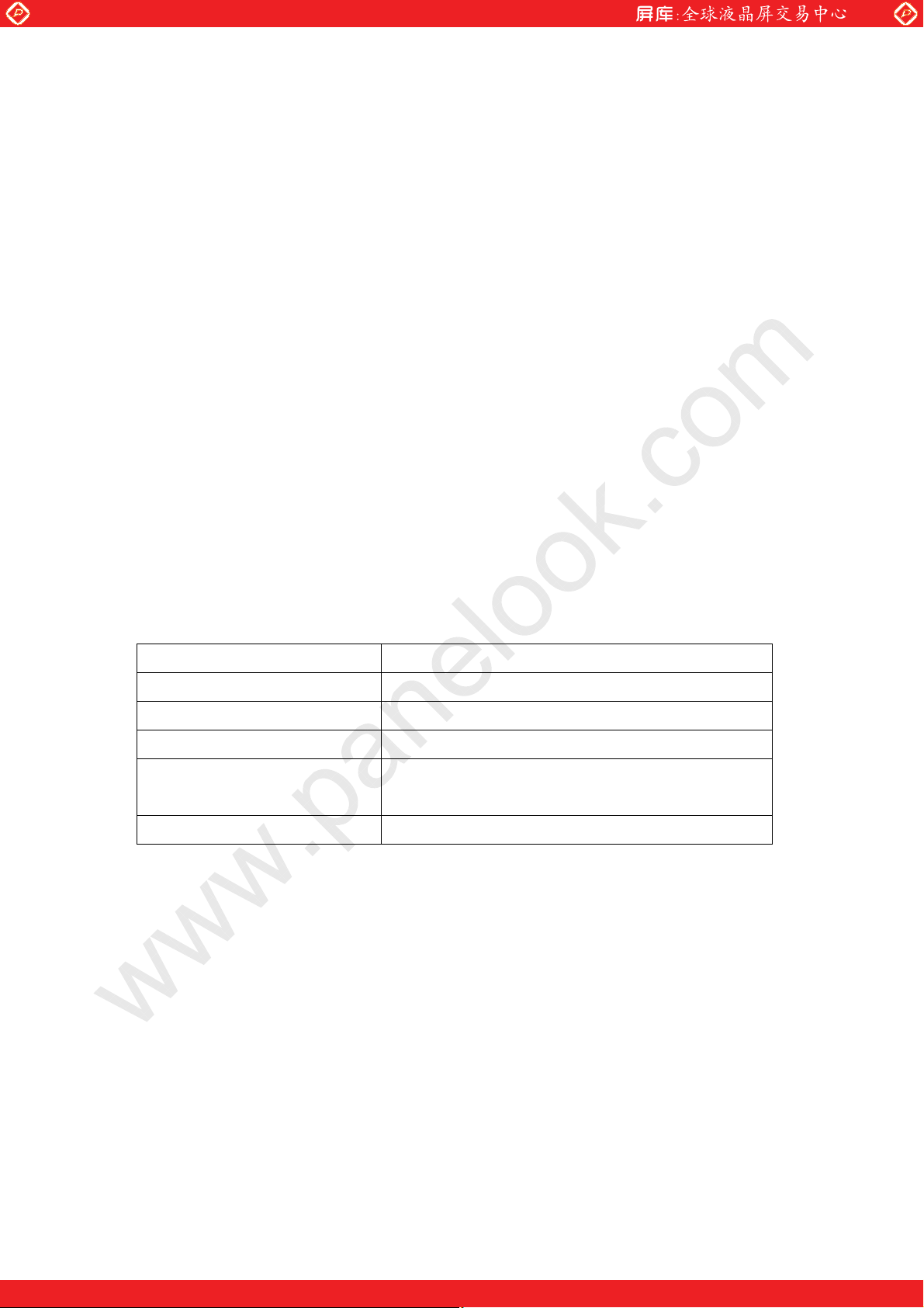
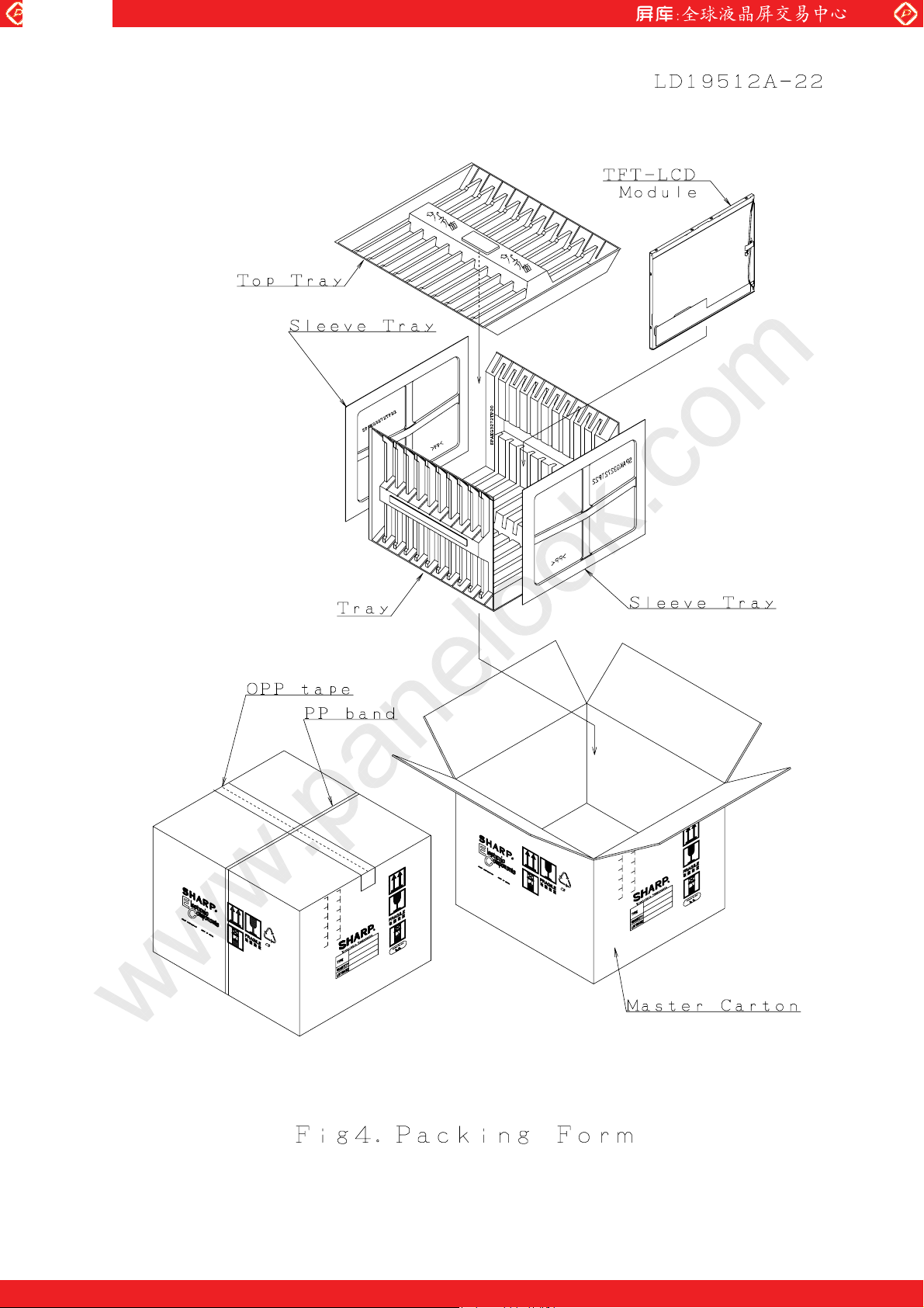
12. Packing form
Product countries / Areas JAPAN , TAIWAN, CHINA
Piling number of cartons 6
Package quantity in one carton 10pcs
Carton size(TYP) 434 x 395 x 338
Total mass of one carton filled
with full modules
Packing form is shown Fig.4
13Kg(TYP)
One step solution for LCD / PDP / OLED panel application: Datasheet, inventory and accessory!
www.panelook.com
Page 21
Global LCD Panel Exchange Center
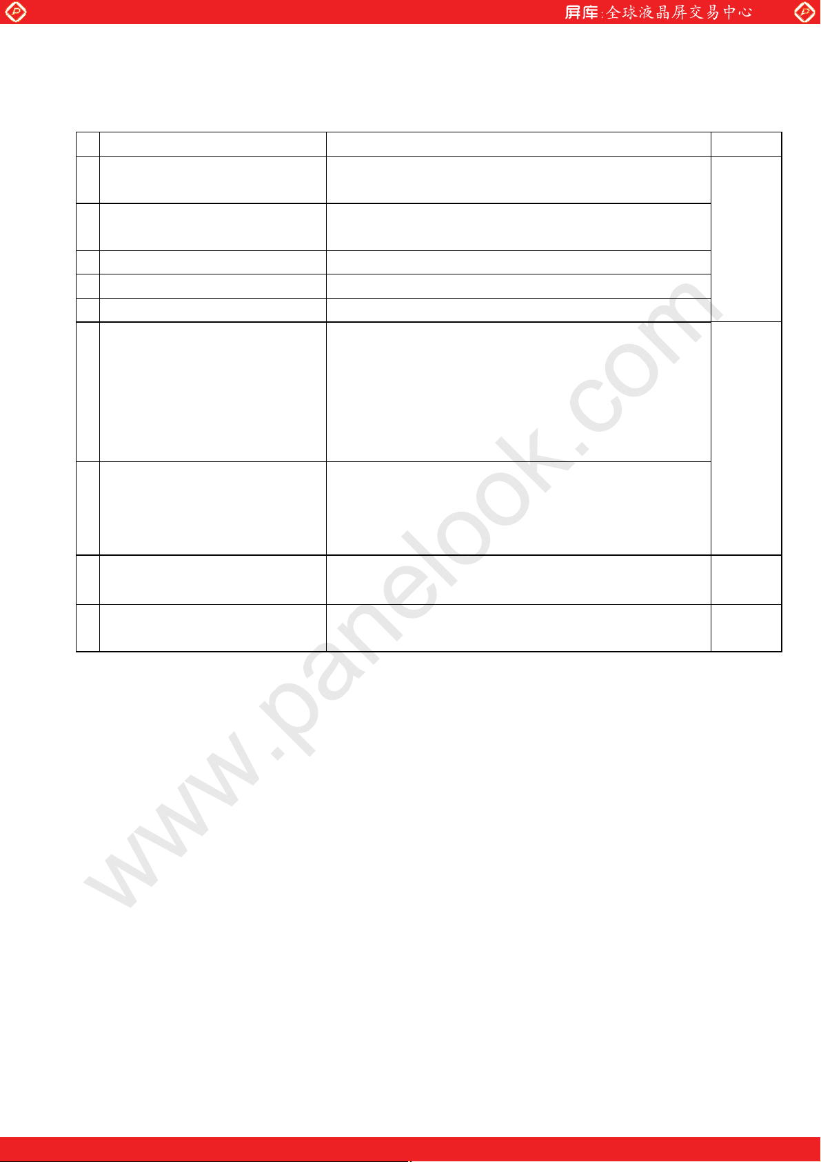
13.Reliability test items
No Test item Conditions
www.panelook.com
LD19512A-19
High temperature
1
& high humidity operation test
2
High temperature operation test
Ta = 40℃ ; 95%RH 240h
(No condensation)
Ta = 60℃(Panel surface
(The panel temp. must be less than 60℃)
High temperature storage test Ta = 60℃ 240h
3
Low temperature operation test Ta = 0℃ 240h
4
Low temperature storage test Ta = -25℃ 240h
5
Vibration test
6
(non- operating)
Waveform : Sine wave
Frequency : 10〜57Hz/Vibration width (one side) : 0.075mm
: 57〜500Hz/Gravity : 9.8m/s
Sweep time : 11minutes
Test period : 3 hours
(1 hour for each direction of X,Y,Z)
Shock test
7
(non- operating)
Max. gravity : 490m/s
Pulse width : 11ms, half-sine wave
Direction : ±X,±Y,±Z,
once for each direction.
Thermal shock test
8
(Storage)
Ta=-25
℃〜60℃
Test period : 10 hours (1 hour for each temperature)
),
2
; 5 cycles
240h
2
Note
【
【
Note
】
】
9
Altitude
Ta=50℃,70kPa,3,048m(10,000ft), t=24h (Operating)
Ta=70℃,12kPa,15,240m(50,000ft), t=24h (Storage)
Note
【
【
】
A gap of panel shall not occur by vibration or the shock.
Result Evaluation Criteria
】
Under the display quality test conditions with normal operation state, these shall be no change
which may affect practical display function. (normal operation state:Temperature:15〜35℃,
Humidity:45〜75%, Atmospheric pressure:86〜106kpa)
One step solution for LCD / PDP / OLED panel application: Datasheet, inventory and accessory!
www.panelook.com
Page 22
Global LCD Panel Exchange Center
RC
(4S)
LQ150X1LG55
14. Others
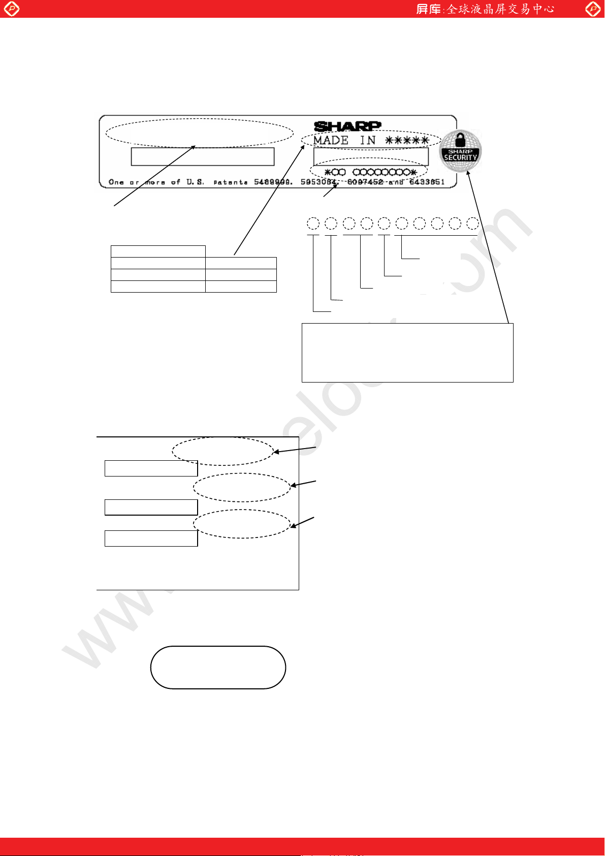
14-1. Lot No. Label:
LQ150X1LG55
www.panelook.com
LD19512A-20
Model number
Product countries / Areas
Japan
Taiwan
China
14-2. Packing box Label:
␠ౝຠ⇟㧦
Barcode
㧸㨛㨠㧺㧻㧚 㧦
(1T)2007.xx.xx
MADE IN JAPAN
MADE IN TAIWAN
MADE IN CHINA
Lot Number
7 0 0 10 03
Security Label
Caution: If this security label is damaged or not pasted on the product
there is a possibility that the product has been counterfeited.
In such cases please contact our company immediately.
.
00※
Serial No.
(5 digits)
Assembly site code
Discernment code
Production month (1-9X, Y, Z)
Production year (Last digit of domi ni cal year)
Model number
Lot number (DATE)
Barcode
㧽㨡㨍㨚㨠㨕㨠㨥㧦
(Q) xx pcs
Quantity of module
Barcode
࡙ࠩຠ⇟ 㧦
シャープ物流用ラベルです。
+PVGTPCN7UG1PN[
R.C.(RoHS Compliance)means these parts have corresponded with the RoHS directive.
※
14-3. If any problem occurs in relation to the description of this specification , it shall be resolved
through discussion with spirit of cooperation.
One step solution for LCD / PDP / OLED panel application: Datasheet, inventory and accessory!
www.panelook.com
Page 23
Global LCD Panel Exchange Center
www.panelook.com
One step solution for LCD / PDP / OLED panel application: Datasheet, inventory and accessory!
www.panelook.com
Page 24
Global LCD Panel Exchange Center
www.panelook.com
One step solution for LCD / PDP / OLED panel application: Datasheet, inventory and accessory!
www.panelook.com
 Loading...