

Page 1
Date: Sep. 30, 1993
LASER PRINTER : JX-9600 SERIES
No. : LPE-173
ADDITION AND ELIMINATION OF PARTS
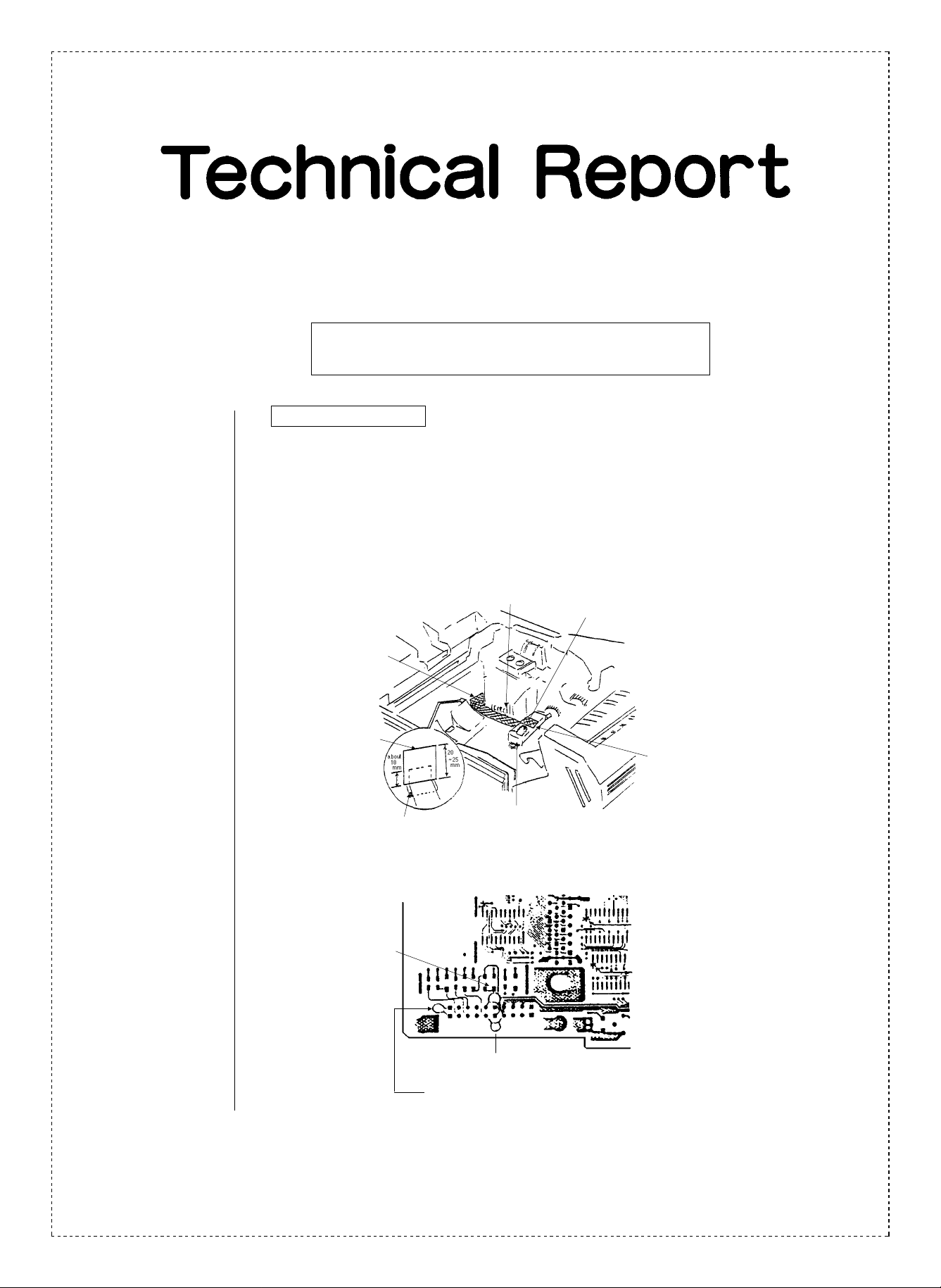
1. Improved EMI levels
1.Model name: JX-9600/JX-9600PS 200V Series
2.General: To improve EMI levels, conductive tape and three capacitors have been added.
➀ Addition of conductive tape
To provide adequate EMI margins, the AC earth plate and the sensor earth plate have
been connected with conductive tape (12.5 x 120 mm).
Conductive tape
Shaft hole
Black tape
Black tape
Start point for attaching
AC earth plate
Sensor earth plate
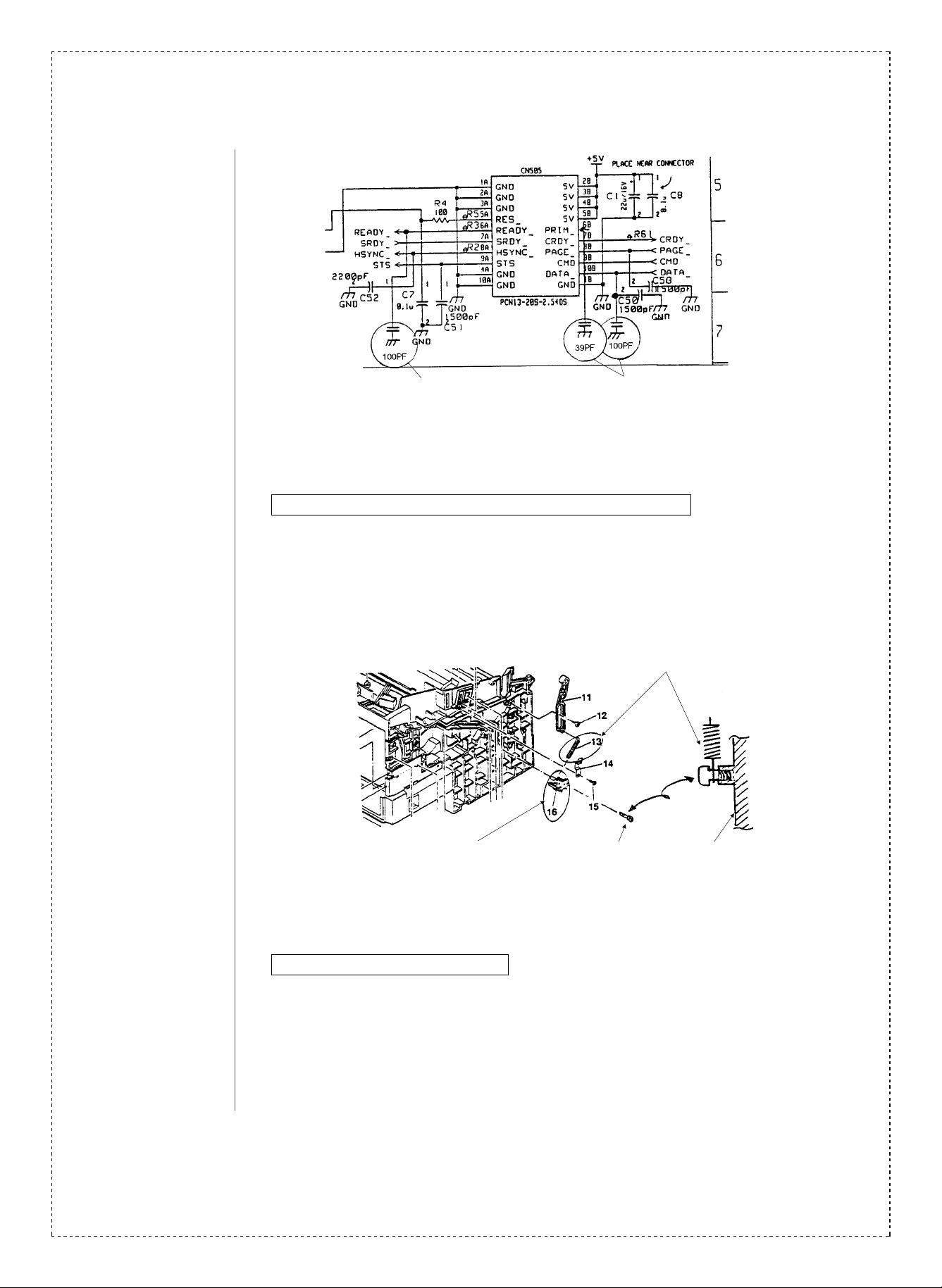
➁ Addition of two 100pF capacitors and one 39pF capacitor to the ICU board
<<ICU board solder side CN 505 area>>
Add a 39pF ceramic
capacitor between the
CN 505 4A and 6B pins.
<Note>
Add an Irax tube to the
pin 4A capacitor pin
Cautions when attaching
1. Make the capacitor pin as
small as possible
2. Make sure no other pins or
parts are touched
Add 100pF ceramic capacitors between CN 505 pins 4A and 6A
Add 100pF ceramic capacitors between CN 505 pins 10A and 10B
SHARP CORPORATION Printer and Scanner Division
1/4
Orange
C
Page 2
Add Add
3.Effective time: June, 1993.
2. Elimination of positioning pins and changes in transport springs
1.Model name: JX-9600, JX-9600PS
2.General: To improve productivity, positioning pins have been eliminated and changes have been
made in the transport springs. Spring screws have been added.
Transport stopper spring change
Eliminate positioning stopper
Add spring screw
3.Effective time: July, 1993.
3. In detecting shield board changes
1.Model name: JX-9400, JX-9600, JX-9600PS
2.General: To improve productivity, the detecting shield board has been changed.
3.Effective time: October, 1993.
2/4
Main frame
Page 3

4. PCU board changes
1.Model name: JX-9400, JX-9600, JX-9600PS charger wire specs
2.General: Along with changing the PCU board CPU to masked ROM, the PCU board unit code
has been changed.
3.Effective time: July, 1993.
5. ICU board improvements
1.Model name: JX-9400
2.General: Jumper wires have been added and 3 pattern cuts have been made to prevent ➀) E4
errors from occurring when inserting and removing ICU board font cards, and ➁) left
margins going out of alignment.
3.Description: Circuit diagram
➀
IU5
1
G
➁
IC5 IC4
1
VPA NC
5
IC4
Changes
(1 pattern cut, 1 jumper wire)
4.Effective time: January, 1993.
FLDOE
IU5
19
19
1
CN502
G
IU4
G
IU4
G
IC5 IC4
15
NVR
IC5 1 pin pattern cut
IC5 1 pin, IC4 5 pin jumper connection
21
Unused
CN501
45
OE
3/4
Page 4

Ref.
Model
No.
1
JX-9600
JX-9600PS
2
JX-9400
3
JX-9600
JX-9600PS
JX-9600
JX-9600PS
4
JX-9400
<Interchange>
1. Interchangeable. 4. Not interchangeable.
2. C urr e nt t y pe c a n be u s ed i n p la ce of new ty pe .
New ty pe cann ot be us ed i n place of curr ent type .
3. C urre nt ty pe cann ot be used i n place of new ty pe.
New t y pe c a n be u sed in pla c e of c u rr en t ty p e.
Parts marked with “ ” is important for maintaining the safety of the set. Be sure to replace these parts with
specified ones for maintaining the safety and performance of the set.
name
Version P/G No.
200V
10
group
200V
10
group
3 -13 MSPRT0073GCZZ MSPRT0130GCZZ AB
3 -16 LPINS0007GCZZ LX-BZ0019GCZZ AB
2 -9 LPLTM0127GCZZ LPLTM0127GCZ1 AB
All
9 -42 VHIM37451SP07 VHIM37451S326 BG
2-6
9 -901
9 -42 VHIM37451SP08 VHIM37451S327 AX
2-6
9 -901
!
Current parts New parts
Parts code Parts code
— VCKYPU1HB101K AA
— VCCCPU1HH390J AA
CPWBF0049GC51 CPWBF0049GC59 BQ
CPWBF0049GC52 CPWBF0049GC60 BQ
Price
rank
5. Interchangeable if replaced with same types of
relate d parts in use .
6. Others.
Parts name
Capacitor
(50wV 100pF)
Capacitor
(50wV 39pF)
Transport
stopper spring
Spring screws
IN detecting
shield board
IC
(M37451S326)
PCU board unit
IC
(M37451S327)
PCU board unit
Effective
time
’93/6 6
’93/6 6
’93/7 5
’93/7 5
’93/10 1
’93/7 3 IC4
’93/7 3
’93/7 3 IC4
’93/7 3
Interchangeability
Note
4/4
 Loading...