

Page 1
q
SERVICE MANUAL
MODEL
CONTENTS
CODE : 00Z
LLT15G1SME
LCD MONITOR
LL-T15G1
LL-E15G1
CHAPTER 1. OUTLINE OF THE PRODUCT,
NOMENCLATURE AND FUNCTION . . . . . . . . . . . . . . . . .1 - 1
CHAPTER 2. CONNECTION, ADJUSTMENT,
OPERATION AND FUNCTIONS . . . . . . . . . . . . . . . . . . . .2 - 1
CHAPTER 3. DISASSEMBLY AND ASSEMBLY . . . . . . . . . . . . . . . . . . .3 - 1
CHAPTER 4. TROUBLESHOOTING . . . . . . . . . . . . . . . . . . . . . . . . . . . .4 - 1
CHAPTER 5.
CONNECTORSIGNALNAME• BLOCK DIAGRAM •
CIRCUIT DIAGRAM • PWB LAYOUT
. . . . . . . . . . . . . . . . . . . .5 - 1
Parts marked with "!" are important for maintaining the safety of the set. be sure to replace these parts with specified
ones for maintaining the safety and performance of the set.
This document has been published to be used
SHARP CORPORATION
for after sales servic e only.
The contents are subject to change without once.
Page 2
CHAPTER 1. OUTLINE OF THE PRODUCT, NOMENCLATURE AND FUNCTION
1. SPECIFICATIONS
■■■■PRODUCT SPECIFICATIONS
• LCD display
38 cm measured diagonally
TFT LCD module
• Resolution (max.)
XGA 1024 u 768 pixels
• Displayable colors (max.)
16.19 million colors (6 bit + FRC2bit)
• Brightness (max.)
260cd/m
• Dot pitch
0.297(H) u 0.297(V) mm
• Contrast ratio
350 : 1
• Angle of visibility
Left-right 160° ; Up-down 150°
• Screen display size
Horizontal 304.1 mm u Vertical 228.1 mm
• Video signal
Analog RGB (0.7Vp-p) [75Ω]
• Sync signal
Separate Sync (TTL level: +/-), Sync on Green,
Composite Sync (TTL level: +/-)
• Expansion compensation
Digital screening (Enlargement of display to correct VGA/SVGA)
• Plug & Play
VESA: DDC1/DDC2B compatible
• Power management
VESA: Based on DPMS
• Input signal terminal
15 pin mini D-sub (3 rows)
• Screen tilt
Upward approx. 0° - 25° ; downward approx. 0° - 5°
• Power supply
AC100-240V, 50/60Hz
(Use special AC adapter, type NL-A60J of Sharp Corporation.)
• Temperature of operating environment
5 - 35°C
• Power consumption
Maximum 35W (3W when in power-saving mode)
(Use special AC adapter.)
• Dimensions (W u D u H)
339 mm u 187 mm u 322 mm
• Weight
Approx. 3.4 kg (Excluding AC adapter and RGB signal cable.)
2
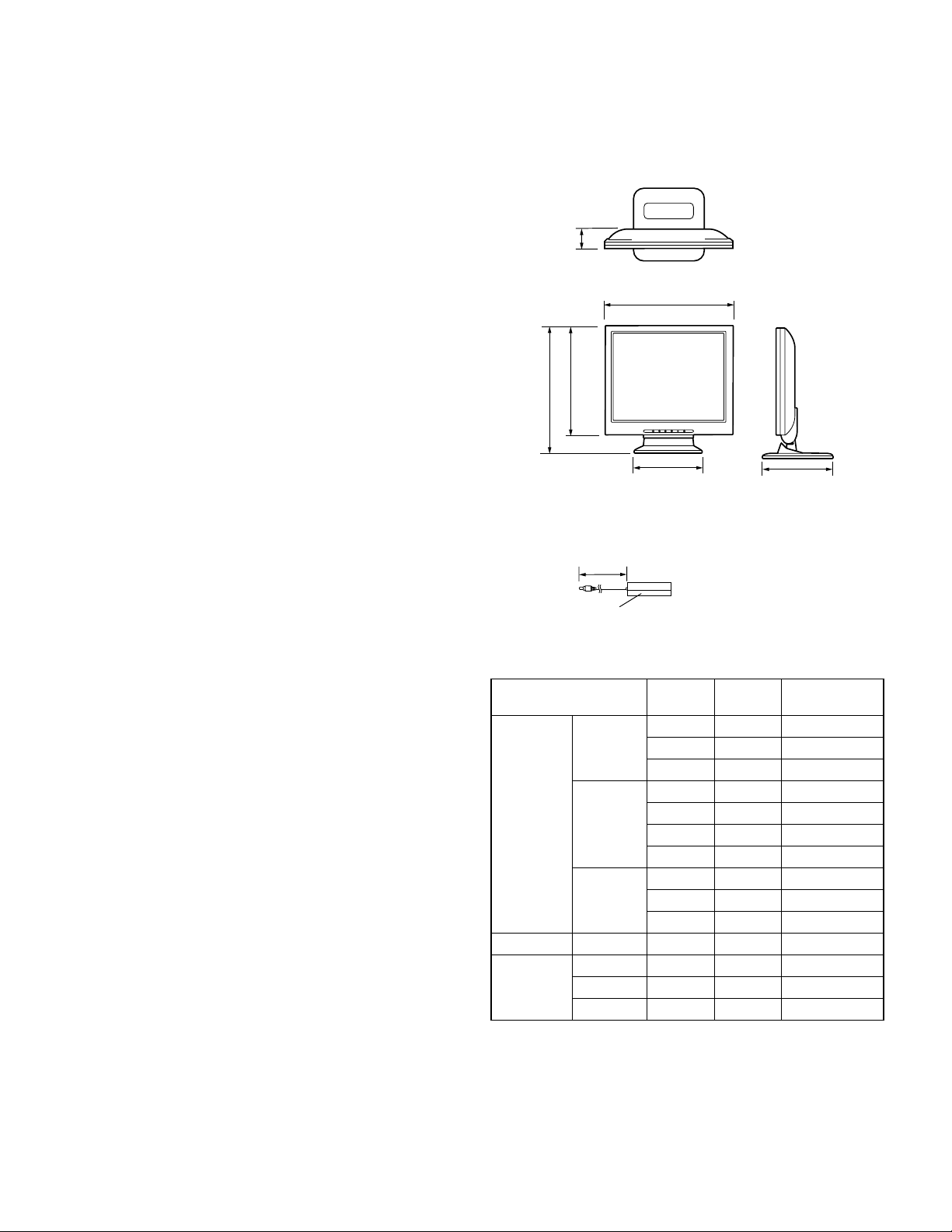
■■■■DIMENSIONS (Units: mm)
47
339
283
322
187
RGB signal cable: Approx.1.8m
Special AC adapter
Approx.1.5m
Approx. W 124mm u D 62 mm u H 36mm
Relevant signal timings
Display mode
VESA 640 u 480 31.5kHz 60Hz 25.175MHz
800 u 600 35.1kHz 56Hz 36.0MHz
1024 u 768
US text 720 u 400 31.5kHz 70Hz 28.3MHz
Power
Macintosh
series
• All are compliant only with non-interlaced.
• Frequencies for Power Macintosh are reference values.
• If the monitor is receiving timing signals that are not compatible, [OUT
OF TIMING] will appear. Follow your computer’s instruction manual
to set the timing to be compatible with the monitor.
• If the monitor is not receiving any signal (synch signal), [NO SIGNAL]
will appear.
640 u 4 80 35.0kHz 66.7Hz 30.2MHz
832 u 6 24 49.7kHz 74.6Hz 57.3MHz
1024 u 768
Hsync
(kHz)
37.9kHz 72Hz 31.5MHz
37.5kHz 75Hz 31.5MHz
37.9kHz 60Hz 40.0MHz
48.1kHz 72Hz 50.0MHz
46.9kHz 75Hz 49.5MHz
48.4kHz 60Hz 65.0MHz
56.5kHz 70Hz 75.0MHz
60.0kHz 75Hz 78.75MHz
60.2kHz 75Hz 80.0MHz
Vsync
(Hz)
187
Dot frequency
(MHz)
LL-T15G1/E15G1 OUTLINE OF THE PRODUCT, NOMENCLATURE AND FUNCTION
1 – 1
Page 3
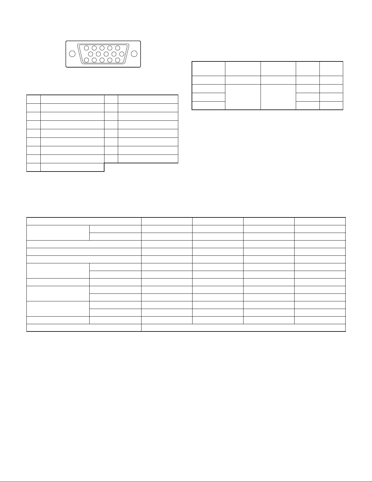
The connector pin Power management
The monitor is based on the VESA DPMS.
To activate the monitor’s Power Management function, both the video
10
15 11121314
(Mini D-sub connector with 15 pins)
25134
6789
No. Function No. Function
1 Red video signal input 9 +5V
2 Green video signal input 10 GND
3 Blue video signal input 11 N.C.
4 GND 12 DDC data
5 GND 13 For H-sync signal input
6 For red video signal GND 14 For V-sync signal input
7 For green video signal GND 15 DDC clock
8 For blue video signal GND
card and the computer must conform to the VESA DPMS standard.
DPMS: Display Power Management Signalling
DPMS mode Screen
ON Display on 35W Yes Yes
STANDBY Display off 3W No Yes
SUSPEND Yes No
OFF No No
DDC (Plug & Play)
This monitor supports the VESA DDC (Display Data Channel) standard.
DDC is a signal standard for carrying out Plug & Play functions on the
monitor or PC. It transfers information such as degree of resolution
between the monitor and PC. You can use this function if your PC is
DDC compliant and if it is set so that it can detect the Plug & Play monitor.
There are many varieties of DDC due to the differences between systems. This monitor works with DDC1 and DDC2B.
Power
consumption
H-sync V-sync
2. TECHNICAL SPECIFICATIONS
Item MIN TYP MAX Unit
Power supply voltage AC 90 100 110 V
DC 11.4 12.0 12.6 V
Working temperature range 0 . +40 °C
Storing temperature range -20 . +60 °C
Humidity range 10 . 90 %RH
Visual angle range Vertical (CR u 5) . 150 . Temperature
Horizontal (CR u 5) . 160 . Temperature
Contrast ratio (CR) (θ = 0°) . 400 ..
Response speed Leading (tr) . 625ms
Trailing (td) . 19 50 ms
Screen white chromaticity (X) 0.273 0.303 0.333 .
(Y) 0.283 0.313 0.343 .
White surface luminance (Y
) . 260 . cd/m
L
Module model number
*Specifications and a part of the appearance are subject to change without notice.
2
LL-T15G1/E15G1 OUTLINE OF THE PRODUCT, NOMENCLATURE AND FUNCTION
1 – 2
Page 4
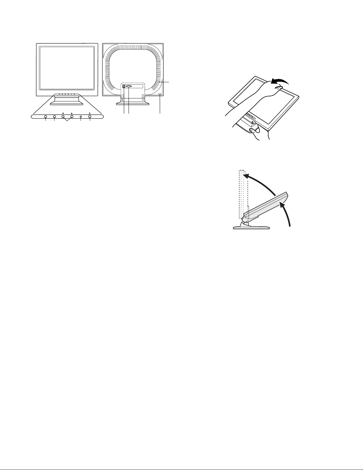
■■■■NOMENCLATURE AND FUNCTION
Control
Panel
MENU SELECT
2
1
345
1 MENU button
This button is used to pop-up, select and close the On Screen Display (OSD) Menu.
2 SELECT button
This button is used to selects menu options when the OSD Menu is
displayed.
3 e d button
When the OSD Menu is displayed:
These buttons are used to increase or decrease the value of a
selected option.
When the OSD Menu is not displayed:
These buttons are used to adjust backlight brightness.
4 POW ER LED
The LED is lit green when in use and orange when in power-saving
mode.
5 Power button
Pressing this button turns the power on. (After turning the power on,
it may take a little time before the screen displays.)
Press the button again to turn the power off.
6 Power terminal
The AC adapter is connected here.
7 RGB input terminal
The RGB signal cable is connected here.
8 Security lock anchor
By connecting a security lock (purchased separately) to the security
lock anchor, the monitor is fixed so that it cannot be transported.
The security slot works in conjunction with Kensington Micro Saver
Security Systems.
9 Ventilation openings
Note: Never block the ventilation openings as this may lead to
overheating inside the monitor and result in malfunction.
67 8
■■■■STANDING UP AND ADJUSTING THE MONITOR
CAUTION!
Caution: Pressure from hands on the LCD panel could cause damage.
Standing up the monitor
Press down on the stand and lift up the top section of the monitor.
9
• Be careful not to pinch your fingers.
• When raising the display section, movement becomes harder in the
middle of travel. Continue raising by applying more force at that
point.
• When the monitor is used with an arm mounting, movement
becomes stiffer to keep the display section from tipping over. This
is not a malfunction.
LL-T15G1/E15G1 OUTLINE OF THE PRODUCT, NOMENCLATURE AND FUNCTION
1 – 3
Page 5
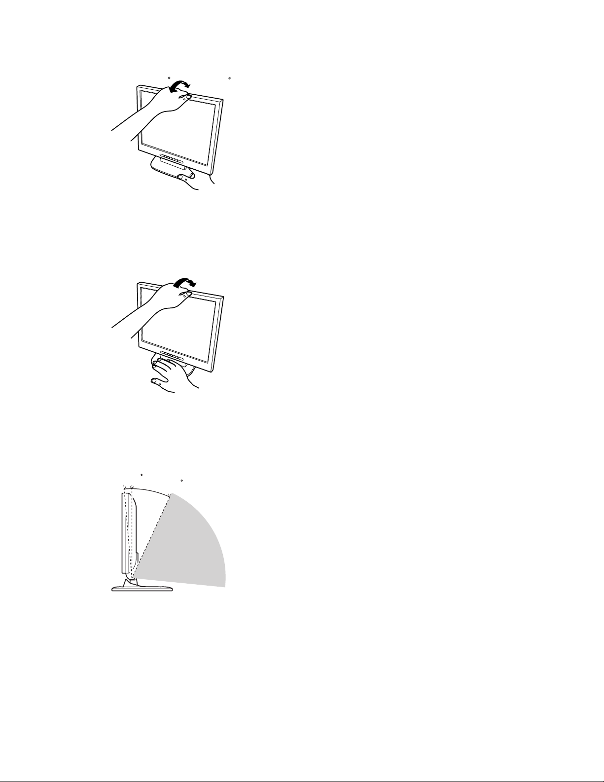
Adjusting the monitor
Press down on the stand and adjust it to a suitable viewing angle.
5
approx. approx.
25
Folding up the monitor
1. Remove the AC adapter and the RGB signal cable.
2. Press down on the stand and gently fold back the monitor.
• Be careful not to pinch your fingers.
• Do not use the monitor when tilted back beyond approximately
25°.The monitor may fall over leading to injury or malfunction.
x.5
appro
approx.25
Prohibited range
LL-T15G1/E15G1 OUTLINE OF THE PRODUCT, NOMENCLATURE AND FUNCTION
1 – 4
Page 6
CHAPTER 2. CONNECTION, ADJUSTMENT, OPERATION AND FUNCTIONS
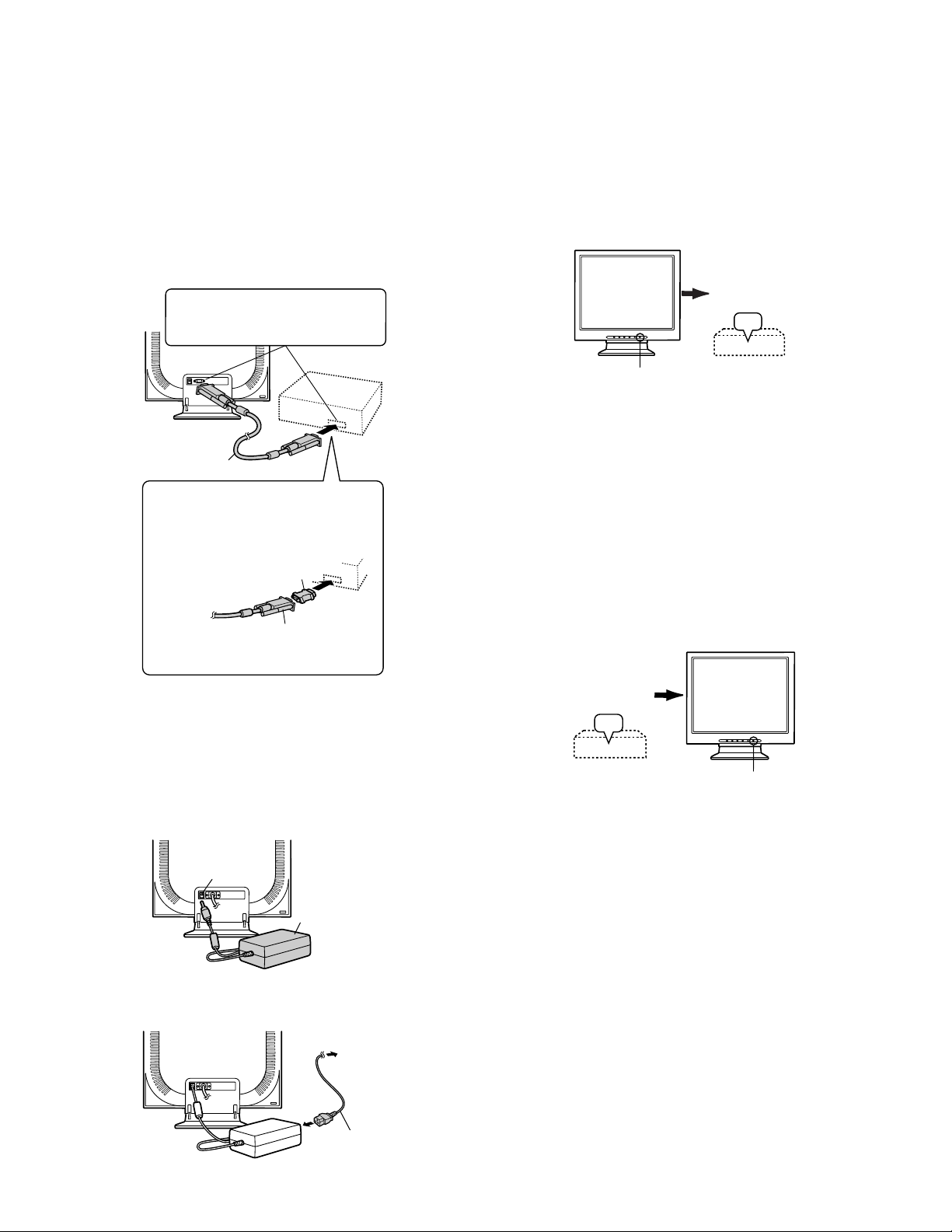
1. CONNECTION
1-1. CONNECTING THE MONITOR TO A COMPUTER
(PC ETC.)
When connecting, ensure that both the monitor and computer are
switched off.
Note: Do not overly bend the cable or add extension cords as this could
lead to malfunction.
Firmly insert the analog RGB terminal
(mini D-sub 15 pin with 3 rows) then
tighten the screws each side.
RGB signal cable
If connecting to a D-sub 15 pin 2 row Apple
Power Macintosh, attach a Macintosh conversion adapter (to be purchased separately) to
the RGB signal cable.
Macintosh conversion adapter
RGB signal cab le
After connecting the adapter, tighten the
screws on each side to fix into place.
1-2. CONNECTING THE MONITOR TO A POWER
SOURCE
Before connecting, first turn off the monitor’s main power switch.
Note: Do not overly bend the cable or add extension cords as this could
lead to malfunction.
1. Connect the AC adapter to the monitor’s power terminal
Power terminal
AC adapter
2. Attach the power cord to the AC adapter and place the power plug
into the AC terminal
AC terminal
Power cord
2. POWER ON/OFF
2-1. TURNING THE POWER ON
1. Press the monitor’s power button.
2. Turn on the computer.
The power LED will be lit green, and the screen will display an image.
Turn on device to
which monitor is
connected
ON
Press power button
Notes: • If using the monitor for the first time or after having changed
the system setting during use, perform an automatic screen
adjustment.
• Depending on the co mput er or O S, it may be nec ess ar y to use
the computer to install monitor set-up i nformation. If so, fo llow
the steps below to install the monitor set-up information.
2-2. TURNING THE POWER OFF
1. Turn the computer off.
2. Press the monitor's power button.
The Power LED will disappear.
If the monitor is not going to be used for a long period of time, be
sure to unplug it from the AC outlet.
Turn off device
to which monitor
is connected
OFF
Press power button
2-3. INSTALLING SET-UP INFORMATION AND THE
ICC PROFILE (FOR WINDOWS).
Depending on the computer or OS, it may be necessary to use the computer to operate the installation of monitor set-up information etc. If so,
follow the steps below to install the monitor set-up information.
(Depending on the type of computer or OS, command names and methods may differ. Please follow the computer’s own operation manual
while reading this.)
■About the ICC profile
An ICC (International Color Consortium) profile is a file that describes the
color characteristics the LCD monitor. By using an application that works
together with an ICC profile, a high color resolution can be realized.
• Windows98, WindowsMe and Windows2000 all use the ICC profile.
• When installing Windows98, WindowsMe and Windows2000 set-up
information (described below), the ICC profile is also installed. If you
would like to install the ICC program only, please refer to Installing
the ICC profile on page 15.
• When using the ICC profile, please set the [WH ITE BALANC E] to [ ST D].
LL-T15G1/E15G1 CONNECTION, ADJUSTMENT, OPERATION AND FUNCTIONS
2 – 1
Page 7

■Installing set-up information
For Windows95
Installing monitor set-up information into Windows95.
This explanation assumes that the floppy disk drive is “A drive”.
1. Place the Utility Disk (provided) into the computer’s A drive.
2. Click on the [Start] button. From [Settings], choose [Control Panel].
3. Double click on [Display].
4. Click on [Settings], [Advanced Properties], and [Monitor], then
[Change].
5. Click on [Have disk], confirm that [Copy manufacturer’s files from:]
is [A:] then click [OK].
6. Confirm that the monitor details are selected, and click [OK].
7. Check that the monitor details are displayed, then click [Apply].
8. Click [OK], and close the window.
9. Remove the Utility Disk from the A drive.
For Windows98
Installing monitor set-up information into Windows98, and setting the
monitor’s ICC profile as a predetermined value.
This explanation assumes that the floppy disk drive is “A drive”.
If the “Add new Hardware Wizard” has appeared:
1. Place the Utility Disk (provided) into the computer’s A drive.
2. Click [Next].
3. Check [Display a list of all the drivers in a specific location, so you
can select the driver you want.], then click [Next].
4. When [Models] is displayed, click on [Have disk], confirm that [Copy
manufacturer’s files from:] is [A:], and click [OK].
5. Confirm that the monitor details are selected, then click [Next],
[Next], and [Finish]. If the “Add New Hardware Wizard” appears,
repeat the installation commands beginning from 2 above.
6. Remove the Utility Disk from the A drive.
If the “Add New Hardware Wizard” has not appeared:
1. Place the Utility Disk in the computer’s A drive.
2. Click on the [Start] button. From [Settings], choose [Control Panel].
3. Double click on [Display].
4. Click on [Settings], [Advanced] and [Monitor].
5. In [Options], check [Automatically detect Plug & Play monitors] and
click on [Change].
6. Click [Next].
7. Click on [Display a list of all the drivers in a specific location, so you
can select the driver you want.], then click [Next].
8. When [Models] is displayed, click on [Have disk], confirm that [Copy
manufacturer’s files from:] is [A:], and click [OK].
9. Confirm that the monitor details are selected, then click [Next],
[Next], and [Finish].
10. Check that the monitor details are displayed, then click [Apply].
11. Click [OK], and close the window.
12. Remove the Utility Disk from the A drive.
For Windows2000
Installing monitor set-up information into Windows2000, and setting the
monitor’s ICC profile as a predetermined value.
This explanation assumes that the floppy disk drive is “A drive”.
1. Place the Utility Disk (provided) into the computer’s A drive.
2. Click on the [Start] button. From [Settings], choose [Control Panel].
3. Double click on [Display].
4. Click on [Settings], [Advanced] and [Monitor].
5. Click on [Properties], [Driver] and [Update Driver].
6. When [Upgrade Device Driver Wizard] appears, click [Next].
7. Check [Display a list of the known drivers for this device so that I
can choose a specific driver] and click [Next].
8. When [Models] is displayed, click on [Have disk], confirm that [Copy
manufacturer’s files from:] is [A:], and click [OK].
9. Select the monitor from the list displayed and click [Next].
10. Click [Next], confirm that the monitor’s name appears on the
screen, and click [Finish]. If [The Digital Signature Not Found]
appears, click [Yes].
11. Click on [Close].
12. Click [OK], and close the window.
13. Remove the Utility Disk from the A drive.
For WindowsMe
Installing monitor set-up information into WindowsMe, and setting the
monitor’s ICC profile as a predetermined value.
This explanation assumes that the floppy disk drive is “A drive”.
If the “Add new Hardware Wizard” has appeared:
1. Place the Utility Disk (provided) into the computer’s A drive.
2. Check [Specify the location of the driver [Advanced]] and click
[Next].
3. Check [Display a list of all the drivers in a specific location, so you
can select the driver you want.], then click [Next].
4. When [Models] is displayed, click on [Have disk], confirm that [Copy
manufacturer’s files from:] is [A:], and click [OK].
5. Select the monitor details from the list, then click [Next], [Next], and
[Finish]. If the “Add new Hardware Wizard” appears, repeat the
installation commands beginning from 2 above.
6. Remove the Utility Disk from the A drive.
If the “Add New Hardware Wizard” has not appeared:
1. Place the Utility Disk in the computer’s A drive.
2. Click on the [Start] button. From [Settings], choose [Control Panel].
3. Double click on [Display].
4. Click on [Settings], [Advanced] and [Monitor].
5. In [Options], check [Automatically detect Plug & Play monitors] and
click on [Change].
6. Check [Specify the location of the driver [Advanced]] and click
[Next].
7. Check [Display a list of all the drivers in a specific location, so you
can select the driver you want.] and click [Next].
8. When [Models] is displayed, click on [Have disk], confirm that [Copy
manufacturer’s files from:] is [A:], and click [OK].
9. Select the monitor details, then click [Next], [Next], and [Finish].
10. Check that the monitor details are displayed, then click [Apply].
11. Click [OK], and close the window.
12. Remove the Utility Disk from the A drive.
LL-T15G1/E15G1 CONNECTION, ADJUSTMENT, OPERATION AND FUNCTIONS
2 – 2
Page 8

■Installing the ICC profile
Installing the monitor’s ICC profile. (If the set-up information has already
been installed, so too has the profile, and there is no need to install it.)
This explanation assumes that the floppy disk drive is “A drive”.
1. Place the Utility Disk in the computer’s A drive.
2. Click on the [Start] button. From [Settings], choose [Control Panel].
3. Double click on [Display].
4. Click on [Settings] and [Advanced].
5. Click on [General] and from [Compatibility] select [Apply the new
display setting without restarting], then click on [Color Management].
1
6. Click [Add], and select [3
7. Choose the color profile that you would like to install, and click on
[Add].
8. Choose the profile and click on [Set As Default].
/2 Floppy [A:]] as the file location.
4. Being careful not to damage the monitor, spread out a soft cloth and
lay the monitor on it display-side down.
5. Attach the arm to the monitor with four screws.
9. Click [OK], and close the window.
10. Remove the Utility Disk from the A drive.
• When using the ICC profile, please set the [WHITE BALANCE] to
[STD].
3. INSTRU CTION S FOR INSTALLING A
VESA COMPLIANT ARM
An arm based on the VESA s tandard can be attached to the monitor.
The arm must be purchased separately.
When choosing the arm to be installed please take note of the following
points.
• The arm should be compatible with the VESA standard, and there
must be a gap of 75mm u 75mm between the screw holes on the section to be attached.
• The arm must not fall off or break off after being attached to the monitor.
Note: Do not overly bend the cable or add extension cords as this
could lead to malfunction.
1. Ensure that both the monitor and computer are switched off.
2. Remove the AC adapter and the RGB signal cable.
Information
The screws used to
attach the arm should be
M4 screws with a length
of 4 mm ~ 6 mm protruding from the surface to be
attached. Using any other
kind of screw may lead to
the monitor falling off or
damage to the internal
part of the monitor.
4 ~ 6 mm
Screw used to
attach arm
Arm
Part of monitor to
which arm is
attached
6. Connect the AC adapter and the RGB signal cable.
3. Press down on the stand and gently fold back the monitor.
Be sure to completely fold the monitor back to stopping point.
If it is attempted to install the arm while the monitor is not completely folded back, the monitor may suddenly fall, leading to malfunction.
Be careful not to pinch your fingers.
LL-T15G1/E15G1 CONNECTION, ADJUSTMENT, OPERATION AND FUNCTIONS
2 – 3
Page 9

4. ADJUSTING THE SCREEN DISPLAY
Adjustment the backlight (right column)
Brightness of backlight can be adjusted.
Automatic screen adjustment
The CLOCK, PHASE, H-POS (horizontal positioning) and V-POS (vertical positioning) functions can be adjusted automatically.
Manual screen adjustment
Fine adjustments can be made using the On Screen Display (OSD)
Menu.
Note: All adjustments will be saved even after turning the power off.
■■■■Resetting all adjustment values
All adjustment values can be returned to their original ex-factory values
in one command.
1. Turn off the monitor power.
2. Press the MENU button and the SELECT button simultaneously,
and while doing this press the power button (i.e. turn the power on).
When [ALL RESET] appears on the screen, the reset is complete.
3. Turn off the monitor power.
Notes: • While ALL RESET is displayed, the control buttons are dis-
abled.
• It is not possible to reset values when the adjustment lock is
in place. Remove the adjustment lock before attempting to
operate control buttons.
■■■■ADJUSTMENT menu reset
The adjustment values of the analogue signal time’s ADJUSTMENT
menu can be returned to their original ex-factory values.
1. Turn on the monitor power.
2. Press the MENU button and the e button simultaneously. When
[RESET] appears on the screen, the reset is complete.
■■■■Adjustment lock function
By disabling the control buttons (i.e. setting the lock) any attempted
changes to adjusted values will be voided.
1. Turn off the monitor power.
2. While pressing the MENU button, press the power button (i.e. turn
the power on).
Continue to press the button until the message appears on the
screen.
When the menu is unlocked:
[ADJUSTMENT LOCKED] will appear on the screen, and the
lock will be set.
When the menu is locked:
[ADJUSTMENT UNLOCKED] will appear on the screen, and the
lock will be removed.
Note: When the lock is in place, all buttons other than the power button
are disabled.
4-1. ADJUSTING THE BACKLIGHT
1. Without the OSD Menu being displayed, press the e button or the d
button.
BRIGHT 31
2. Adjust by pressing the e button (darker) or the d button (lighter).
The BRIGHT bar automatically disappears several seconds after
the last command.
4-2. AUTOMATIC SCREEN ADJUSTMENT
Options in the ADJUSTMENT Menu can be adjusted automatically
(CLOCK, PHASE, H-POS V-POS).
Note: When setting up this monitor for the first time or after having
changed an aspect of the current system, perform an automatic
screen adjustment before use.
■■■■Automatic adjustment screen display
To perform an automatic adjustment, first display an image that makes
the entire screen very bright. If you are using Windows, you can also
use the Adjustment Pattern on the accompanying Utility Disk for Windows.
Displaying the Adjustment Pattern (for Windows)
This explanation is for Windows 95/98/2000/Me, and assumes that the
floppy disk drive is [A drive].
Note: If the floppy disk drive of your computer is not “A drive”, please
read the below substituting the floppy disk drive you are us ing in
place of “A drive” or “A”.
1. Place the Utility Disk (provided) into the computer’s A drive.
2. Open [My Computer] and select [3
3.1, open [File Manager] and choose “A drive”.
3. Double click on [Adj_uty.exe] to run the Adjustment Program. The
Adjustment Pattern will appear.
Adjustment pattern
After completing the adjustment, press the computer’s [Esc] key to
exit the Adjustment Program.
Note: If your computer’s display mode is set to 65K colors, you may
see the different color levels in each color pattern or the gray
scale may look colored. (This is due to the input signal specification and is not a malfunction.)
1
/2 Floppy (A:)]. If using Windows
LL-T15G1/E15G1 CONNECTION, ADJUSTMENT, OPERATION AND FUNCTIONS
2 – 4
Page 10

■■■■Adjusting the screen automatically
1. Press the MENU button.
The ADJUSTMENT Menu will be displayed.
ADJUSTMENT
MANUAL AUTO
CLOCK
PHASE 16
H
-
POS 200
-
POS 29
V
1024X768
V:75Hz H :60.0kHz
2. Press the d button.
The screen will become dark and [ADJUSTING] will be displayed.
After a few seconds the ADJUSTMENT Menu will return. (The automatic adjustment is now complete.)
3. Press the MENU button 4 times to make the On Screen Display
(OSD) Menu disappear.
Notes: • In most cases automatic adjustment is sufficient.
• If necessary due to any of the following, manual adjustments
can be performed after the automatic adjustment.
• When further fine adjustment is needed.
• When the computer’s video input signals are Compos ite
Sync or Sync On Green.
(Automatic adjustments may not be possible.)
127
MENU 1: ADJUSTMENT
ADJUSTMENT
MANUAL AUTO
CLOCK
PHASE 16
H
-
POS 200
V
-
POS 29
1024X768
V:75Hz H :60.0kHz
MANUAL : Individual menu options are manually adjusted.
AUTO : Every menu option is automatically adjusted.
Notes: • Press the d button to select [AUTO].
• To choose a menu option: SELECT button
• To go to the next menu: MENU button
CLOCK
The figure below demonstrates how to adjust so that vertical flicker
noise is not emitted. (e d buttons)
Vertical flicker noise
127
• When [OUT OF ADJUST] is displayed.
(When the screen displays an entirely dark image, the
automatic screen adjustment may be disabled. When
making an automatic adjustment, be sure to either use the
Adjustment Pattern or try displaying an image that makes
the entire screen very bright.)
4-3. MANUAL SCREEN ADJUSTMENT
Adjustments can be made using On Screen Display (OSD) Menu provided.
1. Display an image that ma kes the entire screen very bright. If using
Windows, you can open and use the Adjustment Pattern on the
accompanying Utility Disk.
2. Press the MENU button.
The ADJUSTMENT Menu will be displayed.
ADJUSTMENT
MANUAL AUTO
CLOCK
PHASE 16
H
-
POS 200
V
-
POS 29
1024X768
V:75Hz H :60.0kHz
At this point relevant menu options can be adjusted.
Each time the MENU button is pressed the next menu is selected.
(ADJUSTMENT 3 GAIN CONTROL 3 WHITE BALANCE 3
MODE SELECT 3 OSD Menu disappears)
127
PHASE
The figure below demonstrates how to adjust so that horizontal flicker
noise is not emitted. (e d buttons)
Note: Adjustments to PHASE should be m ade only after CLOCK has
been correctly set.
Horizontal flicker noise
H-POS (horizontal positioning) and V-POS
(vertical positioning)
To center the screen image within the boundaries of the screen, adjust
the left-right (H-POS) values and the up-down (V-POS) values.
(e d buttons)
Screen frame
Adjustment
pattern
Notes: • The OSD Menu automatically disappears approximately 30
seconds after the last command.
• This ex planation is based on using the Adjustment Pattern
(for Windows) to make adjustments.
LL-T15G1/E15G1 CONNECTION, ADJUSTMENT, OPERATION AND FUNCTIONS
2 – 5
Page 11

MENU 2: GAIN CONTROL
GAIN CONTROL
MANUAL AUTO
BL ACK
CONTRAST 80
1024X768
V:75Hz H :60.0kHz
LEVEL 16
MANUAL : Individual menu options are manually adjusted.
AUTO : Every menu option is automatically adjusted using the Auto
Gain Control* function.
Notes: • Press the d button to select [AUTO].
• To choose a menu option: SELECT button
• To go to the next menu : MENU button
* Auto Gain Control function
• The Auto Gain Control adjusts contrast and black level based on
the brightest color of the image displayed. If you are not using the
Adjustment Pattern it is necessary to have an area of 5 mm u 5 mm
of white displayed, and if not adjustments may not be possible. (In
such case, [OUT OF ADJUST] will appear and setting values
remain unchanged.)
• If the signal coming from the computer is composite sync or sync
on green, automatic adjustment cannot be performed. Please perform manual adjustment instead.
BLACK LEVEL
Total screen brightness can be adjusted while watching the color pattern. (e d buttons)
Color pattern
CONTRAST
While watching the color pattern, adjustments can be made so that all
graduations appear. (e d buttons)
MENU 3: WHITE BALANCE
WHITE BALANCE
STD WARM USER
COOL
R
-
CONTRAST
-
CONTRAST
G
-
CONTRAST
B
1024X768
V:75Hz H :60.0kHz
Notes: • On settings other than [STD] not all graduations can be dis-
played. To display all graduations, set to [STD].
• Use the e d buttons to select [COOL], [ • ], [STD], [ • ],
[WARM] or [USER].
• Selecting USER will display the setting values for [R-CONTRAST], [G-CONTRAST] and [B-CONTRAST], in order to
make fine adjustments.
• U se the SELECT button to select [R-CONTRAST], [G-CONTRAST] and [B-CONTRAST].
• To go to the next menu: MENU button
COOL : Color tone bluer than standard
• : Color tone slightly bluer than standard
STD : Color tone standard setting
• : Color tone slightly redder than standard
WARM : Color tone redder than standard
USER
R-CONTRAST : e button for blue-green
d button for red
G-CONTRAST : e button for purple
d button for green
B-CONTRAST : e button for yellow
d button for blue
MENU 4: MODE SELECT
MODE SELECT
OS D
H-
POSITION
V-
OS D
400
SCAL I NG 3
LA NGUAGE
1024X768
V:75Hz H :60.0kHz
Notes: • Depending on the resolution of the input signal, even if menu
options can be selected, the display may not change.
• To choose a menu option : SELECT button
• When adjustment complete: MENU button
OSD H-POSITION (OSD horizont al position)
The position of the OSD display can be moved to the left and right.
(e d buttons)
OSD V-POSITION (OSD vertical position)
The position of the OSD display can be moved up and down. (
400 LINES (degree of resolution)
You can specify the horizontal resolution of a 400-line screen when
using US text, etc. (e d buttons)
640: 640 u 400 dot mode
720: 720 u 400 dot mode (US text etc.)
Note: As the resolution input for other than 400 lines is done automati-
cally, there is no need to set it.
SCALING (Level of scaling)
The sharpness of the image can be adjusted. (e d buttons)
Notes: • When the display mode is set to less than 1024 u 768 pixels,
the display is enlarged to cover the whole screen (i.e. the side
ratio of the display may change).
• If a resolution of 1024 u 768 pixels cannot be achieved even
after expansion is attempted, the screen’s perimeter will display black. (This is not a malfunction.)
COLORS
Maximum display colors can be set. (e d buttons)
260K (260,000) and 16M (16.19 million)
LANGUAGE
Messages displayed on the screen and OSD Menu contents can be
changed to the following languages.
Dutch, English, French, German, Spanish, Italian, Swedish.
1. Press the d button.
The Language Selection Menu will be displayed on the screen.
2. Use the SELECT button to choose a language.
3. Press the MENU button or the d button.
The setting is complete.
POSITION
L I NES 640 720
e d
buttons)
LL-T15G1/E15G1 CONNECTION, ADJUSTMENT, OPERATION AND FUNCTIONS
2 – 6
Page 12

5. ADJUSTMENT
5-1. ADJUSTMENT ITEM LIST
BUTTON ITEM ADJUSTMENT DESCRIPTION
MENU MENU 1:
MENU 1
4
MENU 2
4
MENU 3
4
MENU 4
4
MENU END
SELECT Select the item
< > 0~31 Adjusting the backlight
POWER OFF
ADJUSTMENT
MENU 2:
GAIN CONTROL
MENU 3: WHITE BALANCE
MENU 4:
MODE SELECT
MANUAL CLOCK 0~255 CLOCK: The figure below demonstrates how to
PHASE 0~31 PHASE: The figure below demonstrates how to
H-POS H-POS (horizontal positioning) and
V-POS
AUTO Automatic screen adjustment
MANUAL BLACK LEVEL 0~63 BLACK LEVEL:Total screen brightness can be
CONTRAST 0~100 CONTRAST: While watching the color pattern,
AUTO GAIN CONTROL Menu
COOL • STD • WARM
(5 levels),
USER R • G • B: 0~100
OSD H-POSITION OSD H-POSITION (OSD horizontal position)
OSD V-POSITION OSD V-POSITION (OSD vertical position)
400 LINES 640 • 720 400 LINES (degree of resolution)
SCALING 1~5 SCALING (Level of scaling)
COLORS Maximum display colors can be set. (e d buttons)
LANGUAGE 7 countrys
DEUTSCH, ENGLISH,
ESPANOL, FRANCAIS,
ITALIANO, NE T H ER LAND, SVENSKA
V-POS (vertical positioning)
AUTO: Every menu option is automatically adjusted
WHITE BALANCE Menu
USER
260K (260,000) and 16M (16.19 million)
LANGUAGE
adjust so that vertical flicker noise is not
emitted. (e d buttons)
adjust so that horizontal flicker noise is not
emitted. (e d
To center the screen image within the boundaries of
the screen, adjust the left-right (H-POS) values and
the up-down (V-POS) values. (e d
Options in the ADJUSTMENT Menu can be
adjusted automatically
(CLOCK, PHASE, H-POS V-POS).
using the Auto Gain Control function.
COOL : Color tone bluer than standard
• : Color tone slightly bluer than standard
STD : Color tone standard setting
• : Color tone slightly redder than standard
WARM : Color tone redder than standard
R-CONTRAST : e button for blue-green
G-CONTRAST : e button for purple
B-CONTRAST : e button for yellow
The position of the OSD display can be moved to
the left and right. (e d buttons)
The position of the OSD display can be moved up
and down. (e d buttons)
You can specify the horizontal resolution of a 400line screen when using US text, etc.
(e d buttons)
640: 640 u 400 dot mode
720: 720 u 400 dot mode (US text etc.)
The sharpness of the image can be adjusted.
(e d buttons)
Messages displaye d on the screen and OSD Menu
contents can be changed to the following languages.
Dutch, English, French, German, Spanish, Italian,
Swedish.
e d buttons)
e de d
adjusted while watching the color pattern. (e d buttons)
adjustments can be made so that all
graduations appear. (e d
d button for red
d button for green
d button for blue
e d buttons)
e de d
e d buttons)
e de d
LL-T15G1/E15G1 CONNECTION, ADJUSTMENT, OPERATION AND FUNCTIONS
2 – 7
Page 13

5-2. ADJUSTMENT METHOD
1) Adjusting the backlight
Buttons
2) Resetting all adjustment values
MENU SELECT
Press the above two buttons at same time, and while turn the power on.
3) ADJUSTMENT menu reser
MENU
4) Adjustment lock function
MENU
Power ON
While pressing the MENU button, turn the power on.
5) Automatic screen adjustment
MENU
ADJUSTMENT AUTO
Power ON
Press the two buttons at same time.
SELECT
SELECT
SELECT
SELECT
CLOCK
PHASE
H-POS
V-POS
( buttons)
( buttons)
( buttons)
( buttons)
( buttons)
MENU
MENU
MENU
GAIN CONTROL AUTO
SELECT
SELECT
WHITE BALANCE COOL STD WARM USER
MODE SELECT OSD H-POSITION
SELECT
SELECT
SELECT
SELECT
6) Version display (for service)
Power ON
MENU
Display the software version.
Press the above two buttons at same time, and while turn the power on.
< VERSION & CHECK SUM >
BLACK LEVEL
CONTRAST
( buttons)
OSD V-POSITION
400 LINES
SCALING
LANGUAGE
( buttons)
( buttons)
( buttons)
( buttons)
( buttons)
( buttons)
( buttons)
SELECT
SELECT
SELECT
B-CONTRAST
G-CONTRAST
R-CONTRAST
( SELECT buttons)
( buttons)
( buttons)
( buttons)
VERSION
CHECK SUM : OK DBCF
: 1.01 (20010831)
7) Aging (for service)
Power ON
SELECT
Press the d button, Screen color is changed as following.
Green 3 Light Blue 3 Red 3 Pink 3 Yellow 3 White 3 Blue
When the test is terminate, Power off
AGING TEST
> : SET
MENU : END
LL-T15G1/E15G1 CONNECTION, ADJUSTMENT, OPERATION AND FUNCTIONS
2 – 8
Page 14

CHAPTER 3. DISASSEMBLY AND ASSEMBLY
1. SEPARATING THE LCD FROM THE STAND
1) Remove the screw A and the two screws H, then, remove the hinge cover 2.
2) Remove the four screws B to separate the LCD from the stand.
3) Remove the two screws C and remove the hinge.
4) Remove the two screws i and disassembly the stand.
2. THE LCD SECTION
1) Remove the four screws A and the two screws C, then, remove
the rear panel 1.
2) Remove the two lock screws J and the six screws C, then,
remove the main board shield 2.
3) Remove the four screws F and remove the connec tor b, c, a
and h, then, remove the main board 6.
4) Remove the four screws D, then, remove the inverter shield 3.
5) Remove the four screws G and remove the connec tor d, e, f
and g, then, remove the inverter board 7.
6) Remove the three screws E, then, remove the front cover 4,
LED filter 9, key button F and switch board 5.
7) Remove the four screws K and remove the LCD module 8.
A
C
D
C
D
1
A
H
2
C
B
A
B
i
i
A
J
3
K
E
K
E
G
d
e
h
7
K
G
K
8
g
f
b
c
d
e
f
g
a
E
5
10
9
h
C
2
C
C
F
h
6
a
C
c
b
F
4
LL-T15G1/E15G1 DISASSEMBLY AND ASSEMBLY
3 – 1
Page 15

CHAPTER 4. TROUBLESHOOTING
No power supply
Does LED turns on in green
when power switch is turned
on?
Backlight turns ON?
Yes
Check for RGB cable input
signal.
A
Normal
Replace RGB cable.
Defective
No
No
Check each pin terminal
of connector (W05)
Normal
LED turns on in red?
No
LED turns on in orange?
No
Yes
Yes
Check LED for breakage.
*
Check key cable for disconnection.
*
Yes
Replace any unit (main PWB, SW PWB, cable)
which shows any defect, with a new one.
Check whether the unit is in power save
mode (synchronizing signal is not input.).
1) PC is turned off?
2) RGB cable is disconnected?
3) Synchronizing signal is output from RGB
cable?
No
Synchronizing signal is input to main PWB?
Yes
No
Check inverter PWB unit.
*
Note: Use caution when checking output
side because it has a high voltage.
Normal
Replace LCD module with a
new one.
Defective
Replace inverter PWB
unit with a new one.
LL-T15G1/E15G1 TROUBLESHOOTING
Replace RGB cable
with a new one.
Check power input system.
1) AC adapter
* Normal?
* Connected properly?
2) Blown out fuse (F1)?
3) +5VX, 3.3V, PVD, VDD, VD, 3V3, VLCD,
3V3 signal is output?
4) LED
* Check LED for breakage.
* Check the path between J101 (Pin 3)
and IC101 (Pin 16).
Yes
Replace any defective unit.
[ 1) Adapter, 2) A Main PWB, 3) Switch
PWB] with a new one.
4 – 1
Page 16

Screen does not operate normally.
Check screen condition by changing display modes.
Reset the microprocessor to check if screen condition changes.
(Press and hold MENU and SELECT buttons while turning on power switch.)
A
Screen stays in black. Screen stays in white.
Check RGB cable.
Screen jitters or on-screen
characters flicker.
Defective
Replace RGB cable with
a new one.
Abnormal color
Check the following signals
1) Check if module control signal is output.
2) Check if VLCD voltage is output normally.
Yes No
Main PWB defective.
CLOCK and PHASE
can be adjusted?
Yes No
Switch PWB defective
LL-T15G1/E15G1 TROUBLESHOOTING
4 – 2
Does abnormal area move on
screen when BLACK LEVEL or
CONT is changed after H-POS
or V-POS is set?
Yes No
LCD panel defective.
Page 17

CHAPTER 5. CONNECTOR SIGNAL NAME • BLOCK DIAGRAM •
CIRCUIT DIAGRAM • PWB LAYOUT
1. CONNECTOR SIGNAL NAME
CONNECTOR W01 CONNECTOR W07 CONNECTOR W06
1Red 1GND 1GND
2 Green 2 BO7 2 DCLK
3 Blue 3 BO6 3 GND
4 Ground 4 BO5 4 DE-O
5 Ground 5 BO4 5 VSYNC
6 R-GND 6 GND 6 HSYNC
7G-GND 7 BO3 7 N.C
8 B-GND 8 BO2 8 GND
9 +5V 9 BO1 9 BE7
10 Ground 10 BO0 10 BE6
11 N.C 11 GND 11 BE5
12 (SDA) 12 GO7 12 BE4
13 H-sync 13 GO6 13 GND
14 V-sync 14 GO5 14 BE3
15 (SCL) 15 GO4 15 BE2
16 GND 16 BE1
17 GO3 17 BE0
18 GO2 18 GND
19 GO1 19 GE7
CONNECTOR W04
1 POW1 21 GND 21 GE5
2 GND 22 RO7 22 GE4
3 LED1 23 RO6 23 GND
4 LED2 24 RO5 24 GE3
5 SN1 25 RO4 25 GE2
6SN2 26GND 26GE1
CONNECTOR W05
1 N.C 32 GND 32 RE4
2 CON 33 N.C 33 GND
3 VEE 34 N.C 34 RE3
4 GND 35 N.C 35 RE2
5VDD 36GND 36RE1
20 GO0 20 GE6
27 RO3 27 GE0
28 RO2 28 GND
29 RO1 29 RE7
30 RO0 30 RE6
31 GND 31 RE5
37 RE0
38 VLCD
39 VLCD
40 GND
LL-T15G1/E15G1 CONNECTOR SIGNAL NAME • BLOCK DIAGRAM • CIRCUIT DIAGRAM • PWB LAYOUT
5 – 1
Page 18

2. BLOCK DIAGRAM
MAIN BOARD(TFT LCD DISPLAY ANALOG INTERFACE CONTROL BOARD)
IC01 AD9883
IC04
EEPROM
ISCL
ISDA
IC
05
MTV230
R
G
B
H
V
SCL
SDA
IC03
TLC2933
HSOUT
VSOUT
Camp
Video gain
Video level
Sync processor
and clock
generator input
Sync-processor
and clock
generator
IIC
Control
Register
Input mode
Detection &
Calibration
ADC
DATACLK
HSOUT
VSOUT
SOGOUT
Power
management
FCLK1
Output
Sync-processor
and clock
generator
Control
Center
EEPROM
Interface
VCLK1
R
8
G
8
B
8
Digital
Data
Processor
Scaling
Dithering
OSD
IC02
AM101A-2
TFT
LCD
DC 12Vin
IC07
OSD-R
OSD-G
OSD-B
POWER
Control
LL-T15G1/E15G1 CONNECTOR SIGNAL NAME • BLOCK DIAGRAM • CIRCUIT DIAGRAM • PWB LAYOUT
+5V
+3.3V
5 – 2
Page 19

D
C
B
A
12345678
2 1
3
3. CIRCUIT DIAGRAM
D
C
LL-T15G1/E15G1 CONNECTOR SIGNAL NAME • BLOCK DIAGRAM • CIRCUIT DIAGRAM • PWB LAYOUT
5 – 3
B
8 7 6 5 4
A
Page 20

4. PWB LAYOUT
A SIDE
LL-T15G1/E15G1 CONNECTOR SIGNAL NAME • BLOCK DIAGRAM • CIRCUIT DIAGRAM • PWB LAYOUT
5 – 4
Page 21

B SIDE
LL-T15G1/E15G1 CONNECTOR SIGNAL NAME • BLOCK DIAGRAM • CIRCUIT DIAGRAM • PWB LAYOUT
5 – 5
Page 22

q
COPYRIGHT
No part of this publication may be reproduced,
stored in a retrieval system, or transmitted.
electronic, mechanical, photocopying, recording, or otherwise,
without prior written permission of the publisher.
2002 BY SHARP CORPORATION
All rights reserved.
Printed in Japan.
In any form or by any means,
SHARP CORPORATION
Digital Document Systems Group
Products Quality Assurance Department
Yamatokoriyama, Nara 639-1186, Japan
2002 April Printed in Japan t
 Loading...