

Page 1
LCD Monitor
LCD Farbmonitor
Moniteur LCD
Monitor LCD
Monitor LCD
LL-T2015
OPERATION MANUAL
BEDIENUNGSANLEITUNG
MODE D'EMPLOI
MANUALE D'USO
MANUAL DE FUNCIONAMIENTO
Page 2

Table of Contents/Inhaltsverzeichnis/Table des matières/Indice/Índice
Notice for Users in the USA . . . . . . . . . . . . . . . . . . . . . . . . . . . . . . . . . . . . . . . . . . . . . . . . . . . . . . . . . . . 3
Notice for Users in Europe . . . . . . . . . . . . . . . . . . . . . . . . . . . . . . . . . . . . . . . . . . . . . . . . . . . . . . . . . . . . 4
Notice for Users in the UK . . . . . . . . . . . . . . . . . . . . . . . . . . . . . . . . . . . . . . . . . . . . . . . . . . . . . . . . . . . . . 5
Notice for Users in Australia . . . . . . . . . . . . . . . . . . . . . . . . . . . . . . . . . . . . . . . . . . . . . . . . . . . . . . . . . . . 5
TCO'03 (LL-T2015-H) . . . . . . . . . . . . . . . . . . . . . . . . . . . . . . . . . . . . . . . . . . . . . . . . . . . . . . . . . . . . . . . . 6
TCO'99 (LL-T2015-B) . . . . . . . . . . . . . . . . . . . . . . . . . . . . . . . . . . . . . . . . . . . . . . . . . . . . . . . . . . . . . . . . 7
English . . . . . . . . . . . . . . . . . . . . . . . . . . . . . . . . . . . . . . . . . . . . . . . . . . . . . . . . . . . . . . . . . . 9
Deutsch . . . . . . . . . . . . . . . . . . . . . . . . . . . . . . . . . . . . . . . . . . . . . . . . . . . . . . . . . . . . . . . . 39
Français . . . . . . . . . . . . . . . . . . . . . . . . . . . . . . . . . . . . . . . . . . . . . . . . . . . . . . . . . . . . . . . . 69
Italiano . . . . . . . . . . . . . . . . . . . . . . . . . . . . . . . . . . . . . . . . . . . . . . . . . . . . . . . . . . . . . . . . . 99
Español. . . . . . . . . . . . . . . . . . . . . . . . . . . . . . . . . . . . . . . . . . . . . . . . . . . . . . . . . . . . . . . . 129
Page 3

Notice for Users in the USA
IMPORTANT:
To aid in reporting in case of loss or theft, please
record the monitor's model and serial numbers in
the space provided. The numbers are located on
the rear of the monitor.
Model No.:
Serial No.:
FCC Statement
WARNING – FCC Regulations state that any unauthorized changes or modifications to this equipment
not expressly approved by the manufacturer could void the user's authority to operate this equipment.
Note: This equipment has been tested and found to comply with the limits for a Class B digital device
pursuant to Part 15 of the FCC Rules.
These limits are designed to provide reasonable protection against harmful interference in a
residential installation. This equipment generates, uses and can radiate radio frequency energy and,
if not installed and used in accordance with the instructions, may cause harmful interference to radio
communications. However, there is no guarantee that interference will not occur in a particular
installation. If this equipment does cause harmful interference to radio or television reception, which
can be determined by turning the equipment off and on, the user is encouraged to try to correct the
interference by one or more of the following measures:
- Reorient or relocate the receiving antenna.
- Increase the distance between the equipment and receiver.
- Connect the equipment into an outlet on a circuit different from that to which the receiver is
connected.
- Consult the dealer or an experienced radio/TV technician for help.
EnglishDeutschFrançaisItalianoEspañolEnglish
Use nothing but the included cables and AC cord to insure compliance with FCC regulation for Class B
computing equipment.
Declaration of Conformity
SHARP LCD Color Monitor LL-T2015-H/LL-T2015-B
This device complies with part 15 of the FCC rules. Operation is subject to the following conditions: (1)
this device may not cause harmful interference, and (2) this device must accept any interference
received, including interference that may cause undesired operation.
Responsible Party: SHARP ELECTRONICS CORPORATION
Sharp Plaza, Mahwah, New Jersey 07430
TEL: 1-800-BE-SHARP
* As an ENERGY STA R® Partner, SHARP has determined that this product meets the ENERGY
®
STA R
guidelines for energy efficiency.
This product utilizes tin-lead solder, and fluorescent lamp containing a small amount of mercury.
Disposal of these materials may be regulated due to environmental considerations. For disposal or
recycling information, please contact your local authorities or the Electronics Industries
Alliance: www.eiae.org
3
Page 4

Notice for Users in Europe
This equipment complies with the requirements of Directives 89/336/EEC and 73/23/EEC as amended
by 93/68/EEC.
Dieses Gerät entspricht den Anforderungen der EG-Richtlinien 89/336/EWG und 73/23/EWG mit
Änderung 93/68/EWG.
Ce matériel répond aux exigences contenues dans les directives 89/336/CEE et 73/23/CEE modifiées
par la directive 93/68/CEE.
Dit apparaat voldoet aan de eisen van de richtlijnen 89/336/EEG en 73/23/EEG, gewijzigd door 93/68/
EEG.
Dette udstyr overholder kravene i direktiv nr. 89/336/EEC og 73/23/EEC med tillæg nr. 93/68/EEC.
Quest' apparecchio è conforme ai requisiti delle direttive 89/336/EEC e 73/23/EEC, come emendata
dalla direttiva 93/68/EEC.
ï
ó ó
Este equipamento obedece às exigências das directivas 89/336/CEE e 73/23/CEE, na sua versão
corrigida pela directiva 93/68/CEE.
Este aparato satisface las exigencias de las Directivas 89/336/CEE y 73/23/CEE, modificadas por
medio de la 93/68/CEE.
Denna utrustning uppfyller kraven enligt riktlinjerna 89/336/EEC och 73/23/EEC så som komplette ras
av 93/68/EEC.
Dette produktet oppfyller betingelsene i direktivene 89/336/EEC og 73/23/EEC i endringen 93/68/EEC.
Tämä laite täyttää direktiivien 89/336/EEC ja 73/23/EEC vaatimukset, joita on muutettu direktiivillä 93/
68/EEC.
CAUTION:
TO PREVENT ELECTRICAL SHOCK, DISCONNECT THE AC CORD BEFORE SERVICING.
CAUTION:
FOR A COMPLETE ELECTRICAL DISCONNECTION, PULL OUT THE MAIN PLUG.
VORSICHT:
UM DIE STROMZUFUHR VOLLSTÄNDIG ZU UNTERBRECHEN, DEN NETZSTECKER HERAUSZIEHEN
ENTFERNEN.
ATTENTION :
POUR UN ARRET TOTAL DE L'APPAREIL, DEBRANCHEZ LA PRISE DU COURANT SECTEUR.
VARNING:
FÖR TOTAL ELEKTRISK URKOPPLING, KOPPLA UR KONTAKTEN OCH.
PRECAUCION:
PARA UNA COMPLETA DESCONEXION ELECTRICA DESENCHUFE LA CLAVIJA DE LA RED.
PRECAUCION:
A FIN DE EVITAR DESCARGAS ELÉCTRICAS, DESCONECTE EL ENCHUFE DE LA RED ANTES DE
REALIZAR CUALQUIER OPERACIÓN DE SERVICIO.
ATTENZIONE:
PER EVITARE FOLGORAZIONI, SCOLLEGATE IL CAVO DI COLLEGAMENTO ALLA RETE IN
ALTERNATA PRIMA DI EFFETTUARE UN INTERVENTO DI SERVIZIO TECNICO.
ATTENZIONE:
PER UNO SCOLLEGAMENTO ELETTRICO COMPLETO, TIRATE FUORI LA SPINA PRINCIPALE.
4
Page 5
Notice for Users in the UK
FOR CUSTOMERS IN U.K.
IMPORTANT
The wires in this mains lead are coloured in accordance with the following code:
GREEN-AND-YELLOW : Earth
BLUE : Neutral
BROWN : Live
As the colours of the wires in the mains lead of this apparatus may not correspond with the coloured
markings identifying the terminals in your plug proceed as follows:
• The wire which is coloured GREEN-AND-YELLOW must be connected to the terminal in the plug
which is marked by the letter E or by the safety earth
• The wire which is coloured BLUE must be connected to the terminal which is marked with the
letter N or coloured black.
• The wire which is coloured BROWN must be connected to the terminal which is marked with the
letter L or coloured red.
Ensure that your equipment is connected correctly. If you are in any doubt consult a qualified
electrician.
"WARNING: THIS APPARATUS MUST BE EARTHED."
or coloured green or green-and-yellow.
EnglishDeutschFrançaisItalianoEspañolEnglish
Notice for Users in Australia
Service Inquiries
Please contact your dealer for service if required or contact Sharp Corporation of Australia on
1 300 13 50 22 for referral to your nearest Sharp authorized Service Center.
5
Page 6

Congratulations!
The display you have just purchased carries the TCO'03 Displays
label. This means that your display is designed, manufactured and
tested according to some of the strictest quality and environmental
requirements in the world. This makes for a high performance product,
designed with the user in focus that also minimizes the impact on our
natural environment.
LL-T2015-H
Some of the features of the TCO'03 Display requirements:
Ergonomics
• Good visual ergonomics and image quality in order to improve the working environment for the user
and to reduce sight and strain problems. Important parameters are luminance, contrast, resolution,
reflectance, colour rendition and image stability.
Energy
• Energy-saving mode after a certain time – beneficial both for the user and the environment
• Electrical safety
Emissions
• Electromagnetic fields
• Noise emissions
Ecology
• The product must be prepared for recycling and the manufacturer must have a certified environmental
management system such as EMAS or ISO 14 001
• Restrictions on
- chlorinated and brominated flame retardants and polymers
- heavy metals such as cadmium, mercury and lead.
The requirements included in this label have been developed by TCO Development in cooperation with
scientists, experts, users as well as manufacturers all over the world. Since the end of the 1980s TCO
has been involved in influencing the development of IT equipment in a more user-friendly direction. Our
labelling system started with displays in 1992 and is now requested by users and IT-manufacturers all
over the world.
For more information, please visit
www.tcodevelopment.com
6
Page 7

LL-T2015-B
Congratulations!
You have just purchased a TCO'99 approved and labelled product! Your choice has provided you with a
product developed for professional use. Your purchase has also contributed to reducing the burden on
the environment and also to the further development of environmentally adapted electronics products.
Why do we have environmentally labelled computers?
In many countries, environmental labelling has become an established method for encouraging the
adaptation of goods and services to the environment. The main problem, as far as computers and other
electronics equipment are concerned, is that environmentally harmful substances are used both in the
products and during their manufacture. Since it is not so far possible to satisfactorily recycle the majority
of electronics equipment, most of these potentially damaging substances sooner or later enter nature.
There are also other characteristics of a computer, such as energy consumption levels, that are important
from the viewpoints of both the work (internal) and natural (external) environments. Since all methods of
electricity generation have a negative effect on the environment (e.g. acidic and climate-influencing
emissions, radioactive waste), it is vital to save energy. Electronics equipment in offices is often left
running continuously and thereby consumes a lot of energy.
What does labelling involve?
This product meets the requirements for the TCO'99 scheme which provides for international and
environmental labelling of personal computers. The labelling scheme was developed as a joint effort by
the TCO (The Swedish Confederation of Professional Employees), Svenska Naturskyddsforeningen
(The Swedish Society for Nature Conservation) and Statens Energimyndighet (The Swedish National
Energy Administration).
Approval requirements cover a wide range of issues: environment, ergonomics, usability, emission of
electric and magnetic fields, energy consumption and electrical and fire safety.
The environmental demands impose restrictions on the presence and use of heavy metals, brominated
and chlorinated flame retardants, CFCs (freons) and chlorinated solvents, among other things. The
product must be prepared for recycling and the manufacturer is obliged to have an environmental policy
which must be adhered to in each country where the company implements its operational policy.
The energy requirements include a demand that the computer and/or display, after a certain period of
inactivity, shall reduce its power consumption to a lower level in one or more stages. The length of time to
reactivate the computer shall be reasonable for the user.
Labelled products must meet strict environmental demands, for example, in respect of the reduction of
electric and magnetic fields, physical and visual ergonomics and good usability.
Below you will find a brief summary of the environmental requirements met by this product. The complete
environmental criteria document may be ordered from:
EnglishDeutschFrançaisItalianoEspañolEnglish
TCO Development
SE-114 94 Stockholm, Sweden
Fax: +46 8 782 92 07
Email (Internet): development@tco.se
Current information regarding TCO'99 approved and labelled products may also be
obtained via the Internet, using the address: http://www.tco-info.com/
7
Page 8

Environmental requirements
Flame retardants
Flame retardants are present in printed circuit boards, cables, wires, casings and housings. Their
purpose is to prevent, or at least to delay the spread of fire. Up to 30% of the plastic in a computer casing
can consist of flame retardant substances. Most flame retardants contain bromine or chloride, and those
flame retardants are chemically related to another group of environmental toxins, PCBs. Both the flame
retardants containing bromine or chloride and the PCBs are suspected of giving rise to severe health
effects, including reproductive damage in fish-eating birds and mammals, due to the bio-accumulative*
processes. Flame retardants have been found in human blood and researchers fear that disturbances in
foetus development may occur.
The relevant TCO'99 demand requires that plastic components weighing more than 25 grams must not
contain flame retardants with organically bound bromine or chlorine. Flame retardants are allowed in the
printed circuit boards since no substitutes are available.
Cadmium**
Cadmium is present in rechargeable batteries and in the colour-generating layers of certain computer
displays. Cadmium damages the nervous system and is toxic in high doses. The relevant TCO'99
requirement states that batteries, the colour-generating layers of display screens and the electrical or
electronics components must not contain any cadmium.
Mercury**
Mercury is sometimes found in batteries, relays and switches. It damages the nervous system and is toxic
in high doses. The relevant TCO'99 requirement states that batteries may not contain any mercury. It
also demands that mercury is not present in any of the electrical or electronics components associated
with the labelled unit. There is however one exception. Mercury is, for the time being, permitted in the
back light system of flat panel monitors as there today is no commercially available alternative. TCO
aims on removing this exception when a mercury free alternative is available.
CFCs (freons)
The relevant TCO'99 requirement states that neither CFCs nor HCFCs may be used during the
manufacture and assembly of the product. CFCs (freons) are sometimes used for washing printed circuit
boards. CFCs break down ozone and thereby damage the ozone layer in the stratosphere, causing
increased reception on earth of ultraviolet light with e.g. increased risks of skin cancer (malignant
melanoma) as a consequence.
Lead**
Lead can be found in picture tubes, display screens, solders and capacitors. Lead damages the nervous
system and in higher doses, causes lead poisoning. The relevant TCO'99 requirement permits the
inclusion of lead since no replacement has yet been developed.
*
Bio-accumulative is defined as substances which accumulate within living organisms.
**
Lead, Cadmium and Mercury are heavy metals which are Bio-accumulative.
8
Page 9

Table of Contents
Tips and safety precautions . . . . . . . . . . . . . . . . . . . . . . . . . . . . . . . . . . . . . . . . . . . . . . . . . . . . . . . . . . . . 10
Product description . . . . . . . . . . . . . . . . . . . . . . . . . . . . . . . . . . . . . . . . . . . . . . . . . . . . . . . . . . . . . . . . . . 11
Height adjustment, angle adjustment . . . . . . . . . . . . . . . . . . . . . . . . . . . . . . . . . . . . . . . . . . . . . . . . . . . . 12
Connecting the monitor and turning the monitor on and off . . . . . . . . . . . . . . . . . . . . . . . . . . . . . . . . . . . 13
Connecting the monitor to a computer . . . . . . . . . . . . . . . . . . . . . . . . . . . . . . . . . . . . . . . . . . . . . . . . 14
Connecting the monitor to a power source . . . . . . . . . . . . . . . . . . . . . . . . . . . . . . . . . . . . . . . . . . . . . 15
Turning the power on . . . . . . . . . . . . . . . . . . . . . . . . . . . . . . . . . . . . . . . . . . . . . . . . . . . . . . . . . . . . . . 16
Changing between input terminals . . . . . . . . . . . . . . . . . . . . . . . . . . . . . . . . . . . . . . . . . . . . . . . . . . . 16
Turning the power off . . . . . . . . . . . . . . . . . . . . . . . . . . . . . . . . . . . . . . . . . . . . . . . . . . . . . . . . . . . . . . 17
Adjusting the screen display . . . . . . . . . . . . . . . . . . . . . . . . . . . . . . . . . . . . . . . . . . . . . . . . . . . . . . . . . . . 18
Adjustment value reset . . . . . . . . . . . . . . . . . . . . . . . . . . . . . . . . . . . . . . . . . . . . . . . . . . . . . . . . . . . . . 18
Adjustment lock function . . . . . . . . . . . . . . . . . . . . . . . . . . . . . . . . . . . . . . . . . . . . . . . . . . . . . . . . . . . 18
Adjusting the backlight . . . . . . . . . . . . . . . . . . . . . . . . . . . . . . . . . . . . . . . . . . . . . . . . . . . . . . . . . . . . . 18
Setting display mode . . . . . . . . . . . . . . . . . . . . . . . . . . . . . . . . . . . . . . . . . . . . . . . . . . . . . . . . . . . . . . 19
Checking product information . . . . . . . . . . . . . . . . . . . . . . . . . . . . . . . . . . . . . . . . . . . . . . . . . . . . . . . 19
Adjusting the screen display (With analog connection) . . . . . . . . . . . . . . . . . . . . . . . . . . . . . . . . . . . . . . 20
Automatic screen adjustment . . . . . . . . . . . . . . . . . . . . . . . . . . . . . . . . . . . . . . . . . . . . . . . . . . . . . . . . 20
Manual screen adjustment . . . . . . . . . . . . . . . . . . . . . . . . . . . . . . . . . . . . . . . . . . . . . . . . . . . . . . . . . . 21
Adjusting the screen display (With digital connection) . . . . . . . . . . . . . . . . . . . . . . . . . . . . . . . . . . . . . . 25
Monitor care . . . . . . . . . . . . . . . . . . . . . . . . . . . . . . . . . . . . . . . . . . . . . . . . . . . . . . . . . . . . . . . . . . . . . . . . 28
Monitor care . . . . . . . . . . . . . . . . . . . . . . . . . . . . . . . . . . . . . . . . . . . . . . . . . . . . . . . . . . . . . . . . . . . . . 28
Storage . . . . . . . . . . . . . . . . . . . . . . . . . . . . . . . . . . . . . . . . . . . . . . . . . . . . . . . . . . . . . . . . . . . . . . . . . 28
Troubleshooting . . . . . . . . . . . . . . . . . . . . . . . . . . . . . . . . . . . . . . . . . . . . . . . . . . . . . . . . . . . . . . . . . . 28
Information for customers on environmentally friendly disposal of this SHARP product . . . . . . . . . 29
Specifications . . . . . . . . . . . . . . . . . . . . . . . . . . . . . . . . . . . . . . . . . . . . . . . . . . . . . . . . . . . . . . . . . . . . . . . 30
Installing set-up information and the ICC profile (For Windows) . . . . . . . . . . . . . . . . . . . . . . . . . . . . . . . 33
Information about the ColorSync profile (For MacOS) . . . . . . . . . . . . . . . . . . . . . . . . . . . . . . . . . . . . . . . 36
Instructions for attaching a VESA-compliant arm . . . . . . . . . . . . . . . . . . . . . . . . . . . . . . . . . . . . . . . . . . . 37
EnglishDeutschFrançaisItalianoEspañolEnglish
9
Page 10

Tips and safety precautions
- The TFT color LCD panel used in this monitor is
made with the application of high precision
technology. However, there may be minute
points on the screen where pixels never light or
are permanently lit. Also, if the screen is viewed
from an acute angle there may be uneven colors
or brightness. Please note that these are not
malfunctions but common phenomena of LCDs
and will not affect the performance of the
monitor.
- Do not display a still picture for a long time, as
this could cause an afterimage to remain.
- If the brightness is adjusted to the minimum
setting it may be difficult to see the screen.
- The quality of the computer signal may influence
the quality of the display. We recommend using
a computer able to emit high quality video
signals.
- Never rub or tap the monitor with hard objects.
- Please understand that Sharp Corporation bears
no responsibility for errors made during use by
the customer or a third party, nor for any other
malfunctions or damage to this product arising
during use, except where indemnity liability is
recognized under law.
- This monitor and its accessories may be
upgraded without advance notice.
Location
- Do not use the monitor where ventilation is poor,
where there is a lot of dust, where humidity is high,
or where the monitor may come into contact with
oil or steam, as this could lead to fire.
- Ensure that the monitor does not come into
contact with water or other fluids. Ensure that no
objects such as paper clips or pins enter the
monitor as this could lead to fire or electric
shock.
- Do not place the monitor on top of unstable
objects or in unsafe places. Do not allow the
monitor to come into contact with strong shocks
or vibrations. Causing the monitor to fall or
topple over may damage it.
- Do not use in places where the monitor will be
subject to direct sunlight, near heating
equipment or anywhere else where there is
likelihood of high temperature, as this may lead
to generation of excessive heat and outbreak of
fire.
- When carrying the monitor, firmly grasp both the
display and stand section. If the monitor is lifted
by the display only, the stand may abruptly pop
out or move, and this could lead to injury. If the
monitor is inclined, the stand may move and
cause injury.
- Be careful not to allow your fingers to be
pinched between the display and stand.
(Especially in the area of attachment.)
The Power Cord
- Do not damage the power cord nor place heavy
objects on it, stretch it or over bend it. Also, do
not add extension cords. Damage to the cord
may result in fire or electric shock.
- Use only the power cord supplied with the monitor.
- Insert the power plug directly into the AC outlet.
Adding an extension cord may lead to fire as a
result of overheating.
- Do not remove or insert the power plug with wet
hands. Doing so could result in electric shock.
Monitor and accessory checklist
- Please check that the following items are
included in the package:
- LCD monitor (1)
- Analog signal cable (1)
(model name: QCNW-1041MPZZ)
- Digital signal cable (1)
(model name: QCNW-1088MPZZ)
- CD-ROM (1)
- Operation manual (1)
Notes:
- The analog signal cable (DVI-I29 pin - mini Dsub15 pin) is to be purchased separately.
(model name: NL-C02E)
- The 2-input cable (DVI-I29 pin - DVI-D24 pin/
D-sub15 pin) is to be purchased separately.
(model name: NL-C03J)
- Be sure to use cables that are less than 3 m in
length.
- You are advised to retain the carton in case the
monitor needs to be transported.
- Sharp Corporation holds authorship rights to the
Utility Disk program. Do not reproduce it without
permission.
- The shape of the supplied accessories may not
be exactly same as shown in this manual.
Manual Scope
- In this manual, Microsoft Windows XP will be
referred to as "Windows XP", Microsoft Windows
Millennium as "Windows Me", Microsoft
Windows 2000 as "Windows 2000", Microsoft
Windows 98 as "Windows 98", Microsoft
Windows 95 as "Windows 95", and Microsoft
Windows Version 3.1 as "Windows 3.1". When
there is no need to distinguish between
programs, the term "Windows" will be used.
- Microsoft and Windows are registered
trademarks of Microsoft Corporation.
- Macintosh is a registered trademark of Apple
Computer, Inc.
- All other brand and product names are
trademarks or registered trademarks of their
respective holders.
mini
10
Page 11
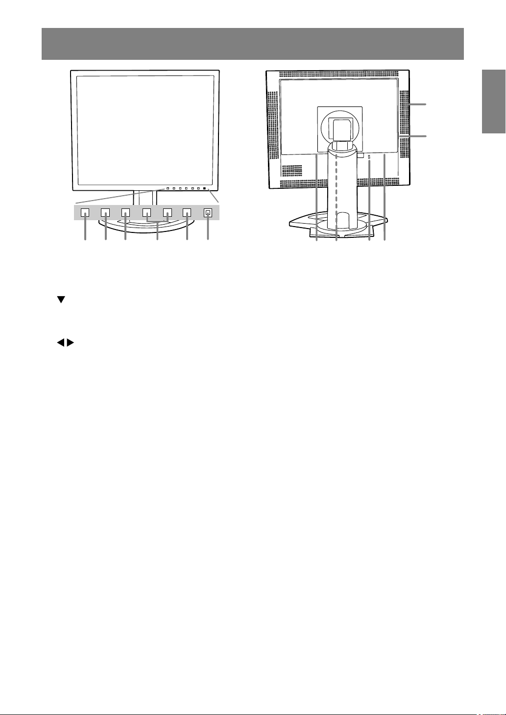
Product description
12
11
2 3 4 5 6
1
1. INPUT button .............................. To switch between the signal's input terminals.
2. MENU button .............................. This button is used to pop-up, select and close the OSD (On Screen
Display) Menu.
/ MODE button ........................ When the OSD Menu is displayed:
3.
This button is used to select menu options.
When the OSD Menu is not displayed:
This button is used to set DISPLAY MODE.
4. buttons ................................ When the OSD Menu is displayed:
5. Power button ............................... Pressing this button turns the power on.
6. Power LED .................................. This LED is lit green when in use and orange when in power-saving
DVI-I input terminal (INPUT-2) ......
7.
Analog RGB input terminal (INPUT-1)
8.
9. Security lock anchor ................... By connecting a security lock (commercially available) to the
10. Power terminal
11. Main power switch
12. Ventilation openings .................. Note: Never block the ventilation openings as this may lead to
These buttons are used to select an option or adjust the value of
the selected option.
When the OSD Menu is not displayed:
These buttons are used to adjust backlight brightness.
Press the button again to turn the power off.
mode.
The computer's digital RGB output terminal or analog RGB output
terminal can be connected here.
For a digital signal input: It can be connected to a computer with a
DVI-compatible output terminal (DVI-D24 pin or DVI-I29 pin) and
which has UXGA output ability. Depending on the computer to be
connected, correct display may or may not be possible.
.... The analog signal cable is connected here. The analog signal cable
included should be used.
security lock anchor, the monitor is fixed so that it cannot be
transported.
The security slot works in conjunction with Kensington Micro Saver
Security Systems.
overheating inside the monitor and result in malfunction.
7
8
10
9
EnglishDeutschFrançaisItalianoEspañolEnglish
11
Page 12
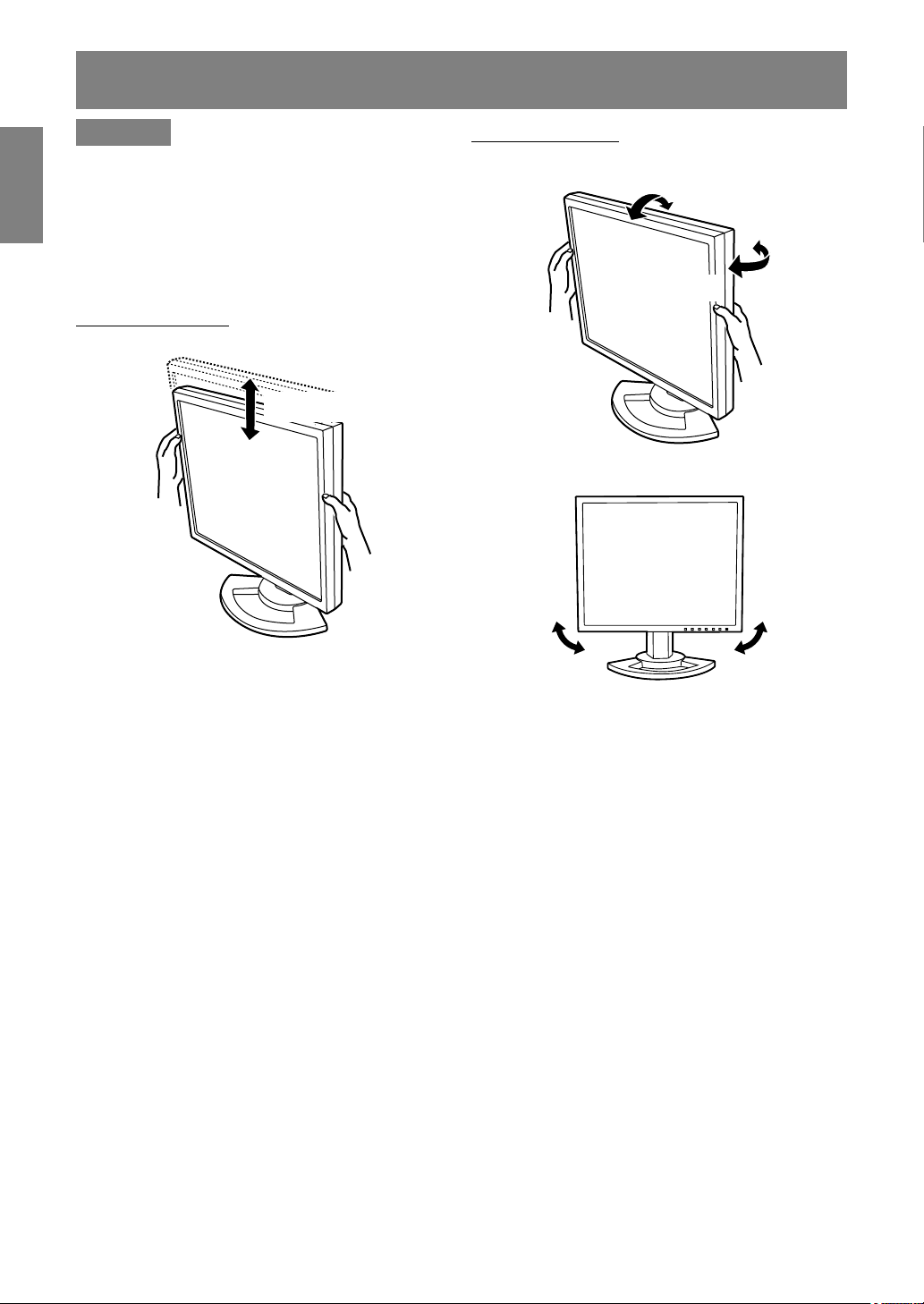
Height adjustment, angle adjustment
CAUTION!
- Be sure to hold both sides of the monitor when
adjusting the viewing angle. The LCD panel
used in this monitor is made of glass. Pressure
from hands on the LCD panel could cause
damage.
- Be careful not to allow your fingers to be
pinched.
Height adjustment
Adjust to an easy to view height.
approx. 60 mm
Angle adjustment
Adjust to an easy to view angle.
approx. 30°
approx. 45°
approx. 5°
approx. 45°
Note:
- Tilt of the display can be finely adjusted.
approx. 1.0°
approx. 1.0°
12
Page 13
Connecting the monitor and turning the monitor on and off
CAUTION!
- When connecting, ensure that both the monitor
and computer are switched off.
- Be careful not to over bend the cable or add
extension cords as this could lead to a
malfunction.
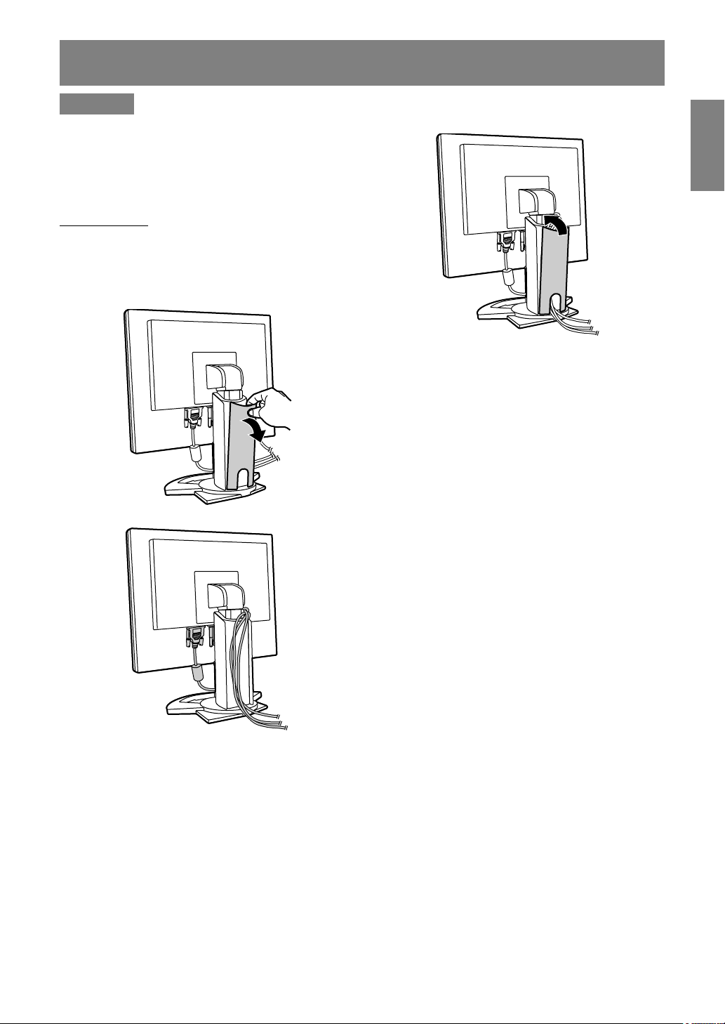
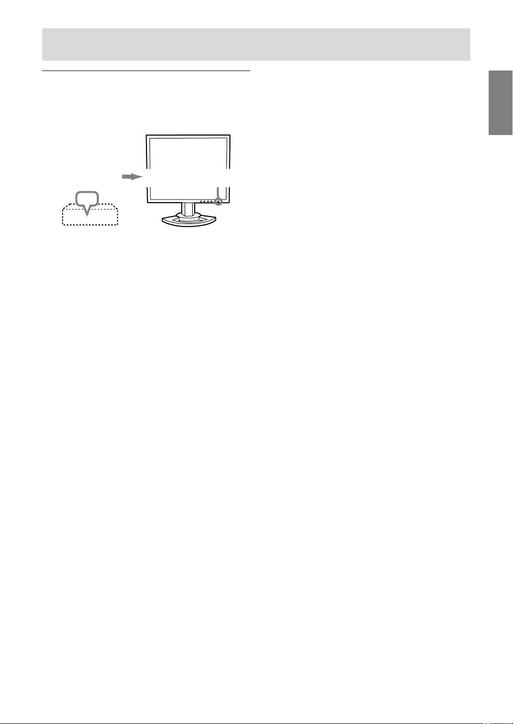
Cable storage
If necessary, excess cable can be housed in the
stand.
1.Remove the cover.
Gently pull the top of the cover towards yourself.
3.Refit the cover.
Be careful not to pinch the cable.
EnglishDeutschFrançaisItalianoEspañolEnglish
- If the cover is hard to refit, do not force it.
Check whether cables are trapped.
2.Run cable along the back of the stand.
13
Page 14
Connecting the monitor and turning the monitor on and off
Connecting the monitor to a computer
The accessory signal cable enables connection of
two computers.
(One analog and one digital connection.)
-
The separately sold 2-input cable enables connection of
two computers to the DVI-I input terminal.
- When using the 2-input cable, set the
connecting input terminal [INPUT-2] to [2LINES]
under the MODE SELECT-2 Menu. (p.24, 27)
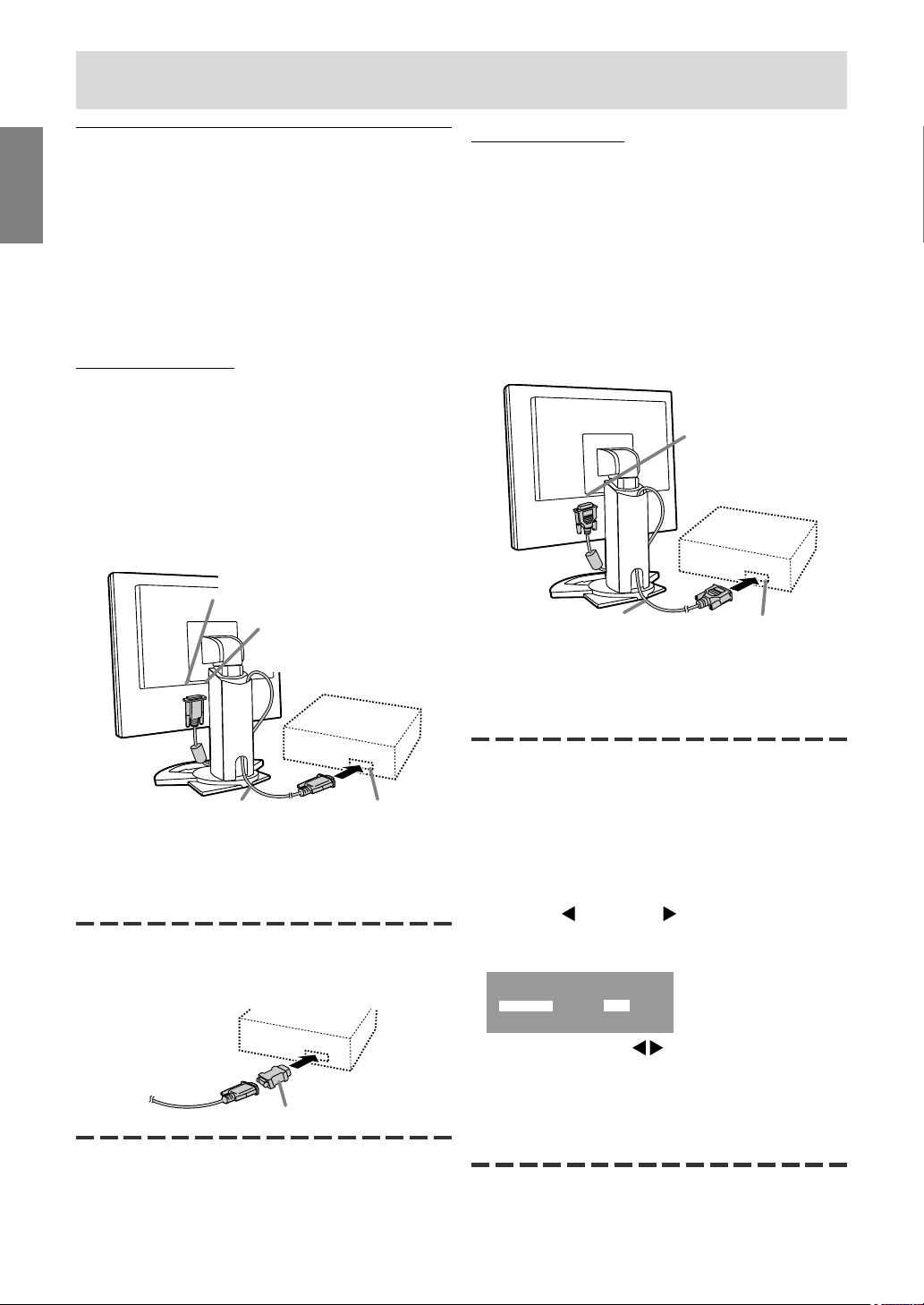
Analog connection
Connect the accessory analog signal cable, or
separately-sold analog signal cable (model name:
NL-C02E) to the analog RGB output terminal of
the computer.
- Connect the accessory analog signal cable to
the analog RGB input terminal (INPUT-1).
- Connect the separately-sold analog signal cable
(model name: NL-C02E) to the DVI-I input
terminal (INPUT-2).
DVI-I input terminal
(INPUT-2)
Analog RGB
input terminal
(INPUT-1)
Digital connection
Connect the accessory digital signal cable to the
digital RGB output terminal of the computer.
- The monitor has an input for connecting to a
computer with a DVI-compatible output
connector (DVI-D24 pin or DVI-I29 pin) and
UXGA output capability. (Depending on the type
of computer to be connected, the display may
not work correctly.)
- Use the accessory digital signal cable.
If using other commercially available digital
signal cables, correct display may not be
achieved.
DVI-I input terminal
(INPUT-2)
Digital signal cable
- Paying attention to connector direction, firmly
insert the signal cable to terminal, and then
tighten the screws at both sides.
Digital RGB output
terminal
Analog signal cable
- Paying attention to connector direction, firmly
insert the signal cable to terminal, and then
tighten the screws at both sides.
If connecting to a D-sub15 pin 2 row Apple Power
Macintosh, attach a Macintosh conversion adapter
(commercially available) to the analog signal cable.
Macintosh conversion adapter
Note:
- If connecting to the Sun Ultra series, a
conversion adapter (commercially available)
may be required.
Analog RGB output
terminal
Set the monitor as follows when establishing a
digital connection with a Power Mac using an ADCDVI adapter made by Belkin. (Operation has been
checked with the Power Mac G4 M7627J/A.)
- Perform settings with the Power Mac power
supply off.
1.After connecting the power cord, turn on the
monitor's main power.
2.Press the button and button simultaneously,
and while doing this press the power button (i.e.
turn the power on).
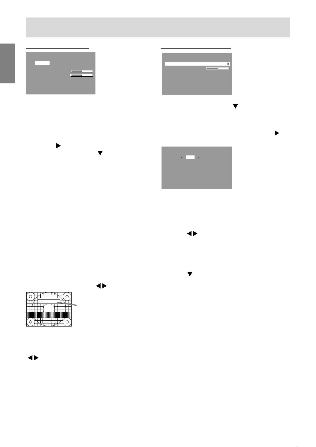
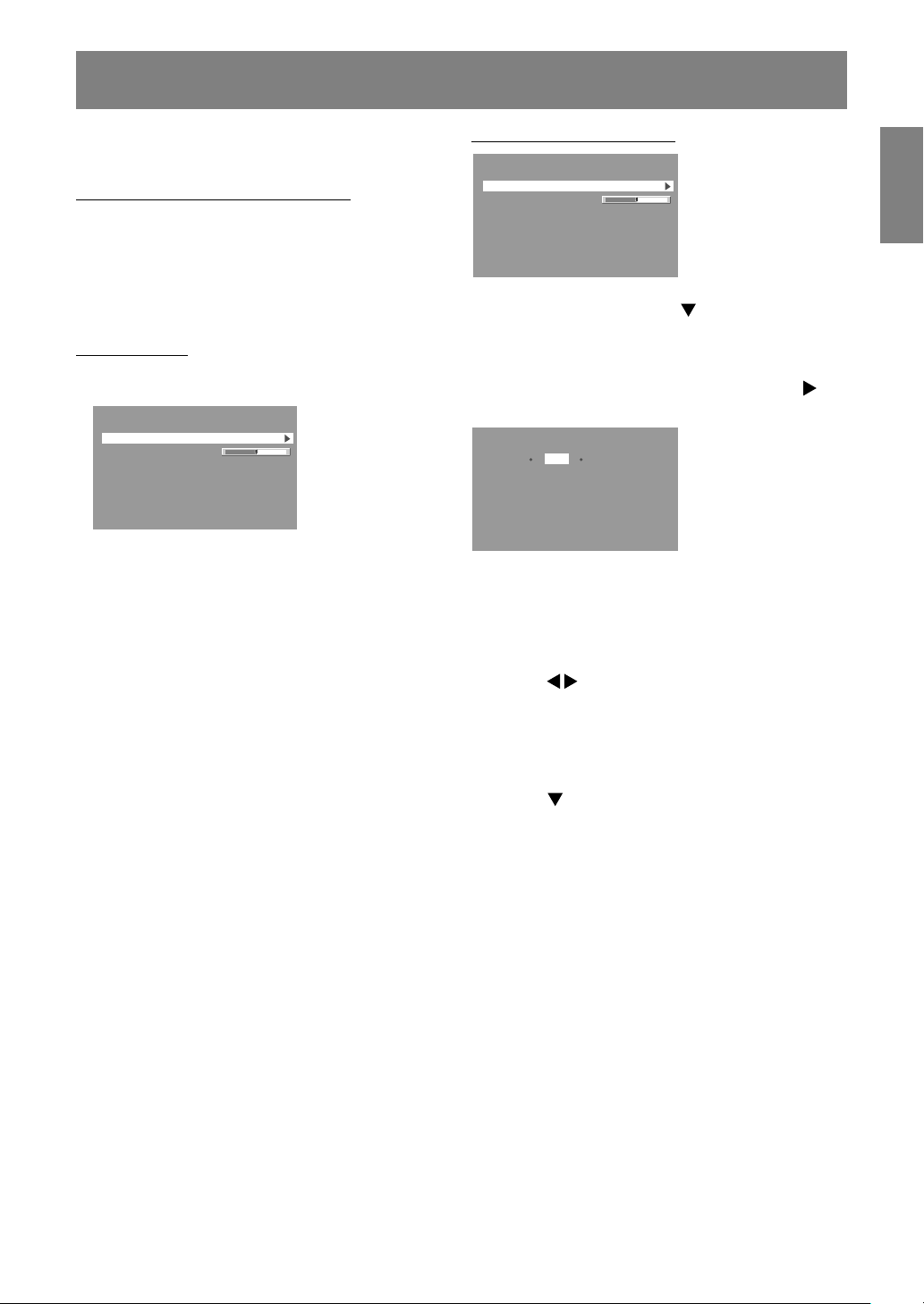
MAC DIGITAL
INPUT-2 OFF ON
3.Set to [ON] with the buttons.
- Do not set to [ON] if you are not using a Belkin
ADC-DVI adapter, as this may result in
incorrect display.
4.Press the MENU button.
This completes setting.
14
Page 15
Connecting the monitor and turning the monitor on and off
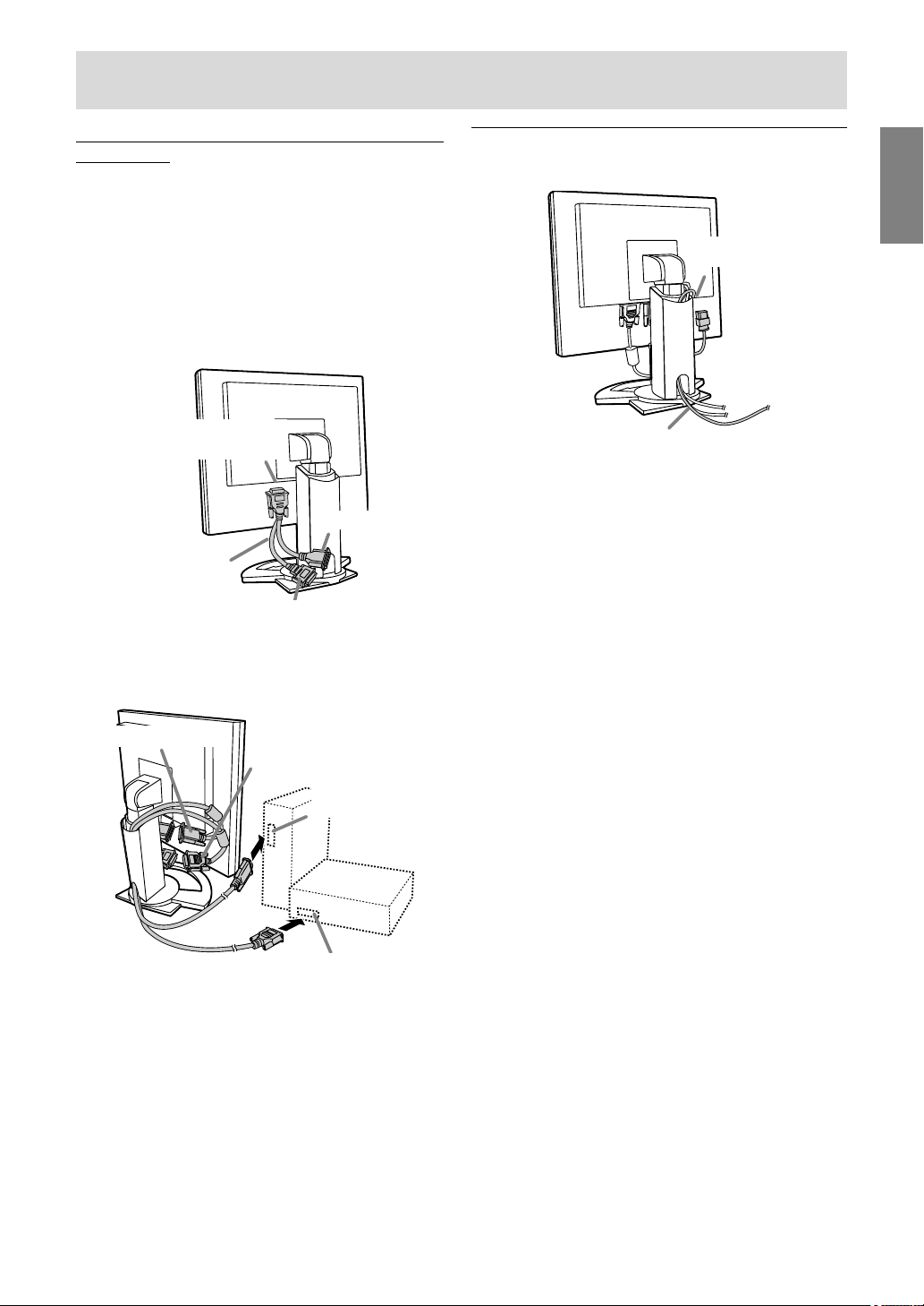
When connecting using a separately sold 2input cable
The separately sold 2-input cable (model name:
NL-C03J) enables connection between the DVI-I
input terminal on the monitor and the two PCs.
(One analog and one digital connection.)
1.Connect the 2-input cable to the DVI-I input
terminal of the monitor.
2.Connect the accessory or commercially
available analog signal cable and the accessory
digital signal cable to the 2-input cable.
DVI-I input terminal
(INPUT-2)
mini D-sub15 pin
2-input cable
(purchased separately)
DVI-D24 pin
- When using commercially available analog
signal cable, both ends should be mini D-sub
15 pin.
3.Connect each signal cable to the computers.
Connecting the monitor to a power
source
EnglishDeutschFrançaisItalianoEspañolEnglish
Power terminal
AC outlet
Power cord
Analog signal cable
Digital signal cable
Analog RGB
output terminal
Digital RGB output terminal
- Paying attention to connector orientation,
firmly insert the signal cable into the PC, and
then tighten the screws at both sides.
Notes:
- When using the 2-input cable, set the
connecting input terminal [INPUT-2] to [2LINES]
under the MODE SELECT-2 Menu. (p.24, 27)
- The monitor connected to the 2-input cable by
analog connection may not be automatically
recognized and setup under Plug & Play.
Perform storage of setup information manually.
(p.33)
15
Page 16
Connecting the monitor and turning the monitor on and off
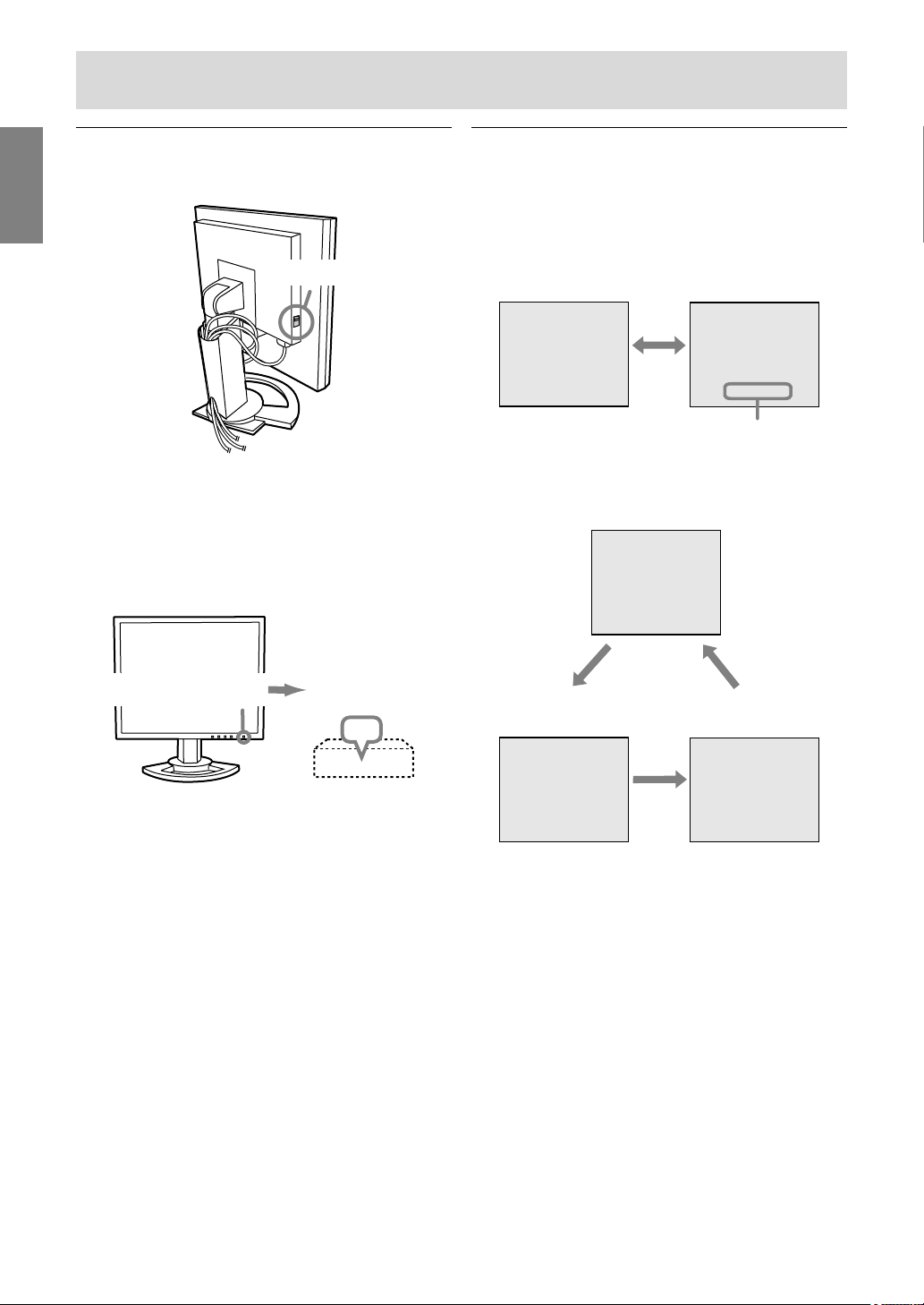
Turning the power on
1.Turn on the main power of the monitor.
Main power switch
- When switching the main power switch on and
off, always wait for an interval of at least 5
seconds. Rapid switching may result in
malfunction.
2.Press the monitor's power button.
The power LED will light up orange.
3.Turn on the computer.
Turn on the
Press power button.
computer power
supply.
ON
Changing between input terminals
Use the INPUT button to switch between signal
input terminals.
When not using a 2-input cable
Analog RGB input terminal
INPUT-1
<ANALOG>
When using a 2-input cable
Analog RGB input terminal
<ANALOG>
INPUT
DVI-I input terminal
(analog)
DVI-I input terminal
INPUT
INPUT-2
< >
<ANALOG> or <DIGITAL>
INPUT-1
INPUT
DVI-I input terminal
(digital)
When a signal is input from the computer, the
power LED lights up green, and the screen is
displayed. (After power is turned on, it may take
a little time until the screen is displayed.)
- If the input terminal to which the computer is
connected has not been selected, the screen
will not be displayed. If necessary, perform
input terminal switching. (right column)
Notes:
- When using an analog signal, perform an
automatic screen adjustment under the following
conditions (p.20):
- Using the monitor for the first time.
- After having changed the system settings
during use.
- Depending on the type of computer or OS, you
may need to install the monitor set-up
information on your system. (p.33)
- When connecting to a notebook, if the notebook
computer's screen is set to display at the same
time, the MS-DOS screen may not display
properly. In this case, change the setting to
display only the LCD monitor.
INPUT2-A
<ANALOG>
INPUT
INPUT2-D
<DIGITAL>
Note:
- When there is no input signal, [NO SIGNAL] is
displayed.
16
Page 17
Connecting the monitor and turning the monitor on and off
Turning the power off
1.Turn the computer off.
2.Press the monitor's power button.
The power LED will disappear.
EnglishDeutschFrançaisItalianoEspañolEnglish
Turn the computer
off.
OFF
If the monitor will not be used for a long time, turn
off the main power switch of the monitor, and
remove the power plug from the outlet.
Press power button.
17
Page 18
Adjusting the screen display
For analog signal
1.First perform an automatic adjustment. (p.20)
2.Perform manual adjustment where necessary.
(p.21)
For digital signal
The monitor can generally be used without
adjustment. If necessary perform manual
adjustment. (p.25)
Note:
- All adjustments will be saved even after turning
the power off.
Adjustment value reset
Resetting all adjustment values
All adjustment values can be returned to their
original ex-factory values in one command.
1.Turn off the monitor power.
2.Press the MENU button and the
button simultaneously, and while doing this
press the power button (i.e. turn the power on).
Continue to press the buttons until [ALL RESET]
appears on the screen. Reset is complete when
the displayed message disappears.
Notes:
- While [ALL RESET] is displayed, the control
buttons are disabled.
- It is not possible to reset values when the
adjustment lock is in place. Remove the
adjustment lock before attempting to operate
control buttons.
/ MODE
Adjustment lock function
By disabling the control buttons (i.e. setting the
lock) any attempted changes to adjusted values will
be voided.
1. Turn off the monitor power.
2.While pressing the MENU button, press the
power button (i.e. turn the power on).
Continue to press the buttons until
[
ADJUSTMENT LOCKED
screen. The lock is set when the message is
displayed.
Note:
- When the lock is in place, all buttons other than
the power button are disabled.
] appears on the
Adjustment lock release
1.Turn off the monitor power.
2.While pressing the MENU button, press the
power button (i.e. turn the power on).
Continue to press the buttons until
[
ADJUSTMENT UNLOCKED
screen. The lock is released when the message
is displayed.
] appears on the
Adjusting the backlight
1.Without the OSD Menu being displayed, press
the or the button.
BR I GHT 31
-
+
ADJUSTMENT Menu reset
Settings of items in the ADJUSTMENT Menu
(CLOCK, PHASE, H-POS, V-POS) can be returned
to their original ex-factory values.
1.Turn on the monitor power.
2.Press the MENU button and the
simultaneously. When [RESET] appears on the
screen, the reset is complete.
Notes:
- While [RESET] is displayed, the control buttons
are disabled.
- It is not possible to reset values when the
adjustment lock is in place. Remove the
adjustment lock before attempting to operate
control buttons.
button
2.Adjust by pressing the button (darker) or
button (lighter).
Note:
- On Screen display for adjustment disappears
several seconds after the last operation.
18
Page 19

Adjusting the screen display
Setting display mode
Color tone or brightness can be changed with one
command.
STD
Displays image with the color tone results from
original scheme of liquid crystal panel.
OFFICE
Display brightness is lowered. (This mode saves
power.)
sRGB
sRGB is international standard of color
representation specified by IEC (International
Electrotechnical Commission).
Color conversion is made in taking account of
liquid crystal's characteristics and represents
color tone close to its original image.
VIVID
Displays an image with dynamic and vivid
primary colors.
- If [DISPLAY MODE] is set to [sRGB] or [VIVID],
[WHITE BALANCE] is set to [STD].
Checking product information
A model name (MODEL), a serial no. (S/N), and
usage time (USAGE TIME) of the monitor can be
checked.
1.Turn the power off.
2.While pressing the / MODE button, press the
monitor's power button (i.e. turn the power on).
3.Checking done: MENU button
Note:
- Please note that the indication of usage time at
purchase may not be 0 (zero), as a result of
factory inspection and other activities during
manufacture.
EnglishDeutschFrançaisItalianoEspañolEnglish
How to set
Press the
not displayed.
Each time the button is pressed the next menu
item appears. (STD OFFICE sRGB VIVID
STD)
On Screen display for adjustment disappears
several seconds after the last operation.
/ MODE button when the OSD Menu is
19
Page 20
Adjusting the screen display (With analog connection)
Automatic screen adjustment
Options in the ADJUSTMENT Menu can be
adjusted automatically (CLOCK, PHASE, H-POS,
V-POS).
Note:
- When setting up this monitor for the first time or
after having changed an aspect of the current
system, perform an automatic screen adjustment
before use.
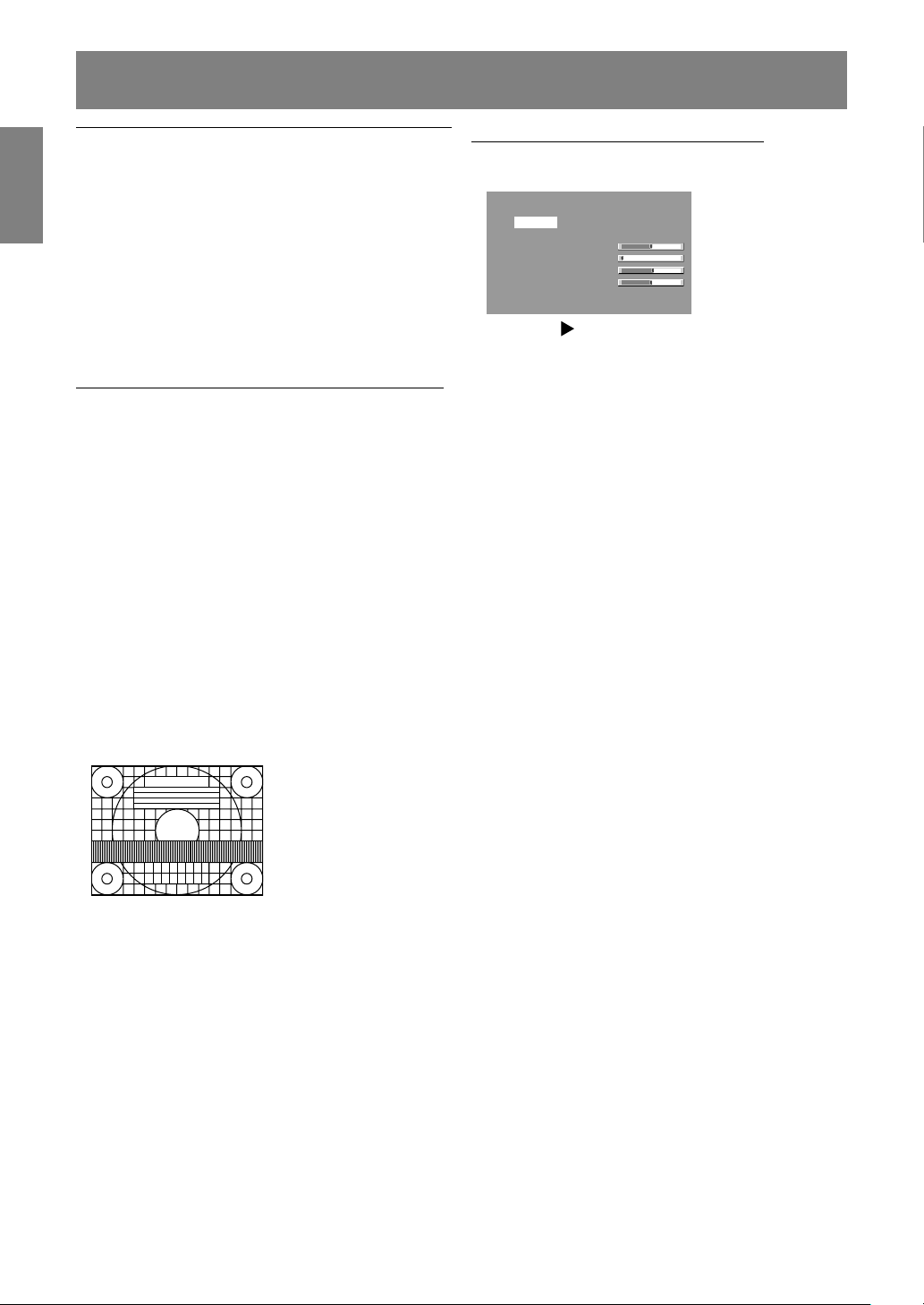
On Screen Display for the automatic adjustment
First display an image that makes the entire
screen light.
If you are using Windows, you can use the
Adjustment Pattern on the accompanying CD-ROM.
Opening the Adjustment Pattern (for Windows)
This explanation is for Windows 95/98/2000/Me/
XP, and assumes that the CD-ROM drive is "D"
drive.
1.Load the accessory CD-ROM into the CD-ROM
drive of the computer.
2.Open [My Computer] and select CD-ROM. If
using Windows 3.1, open [File Manager] and
choose "D" drive.
3.Double click on [Adj_uty.exe] to run the
Adjustment Program. The Adjustment Pattern
will appear.
Adjustment Pattern
After completing the adjustments, press the
computer's [Esc] key to exit the Adjustment
Program.
Adjusting the screen automatically
1.Press the MENU button.
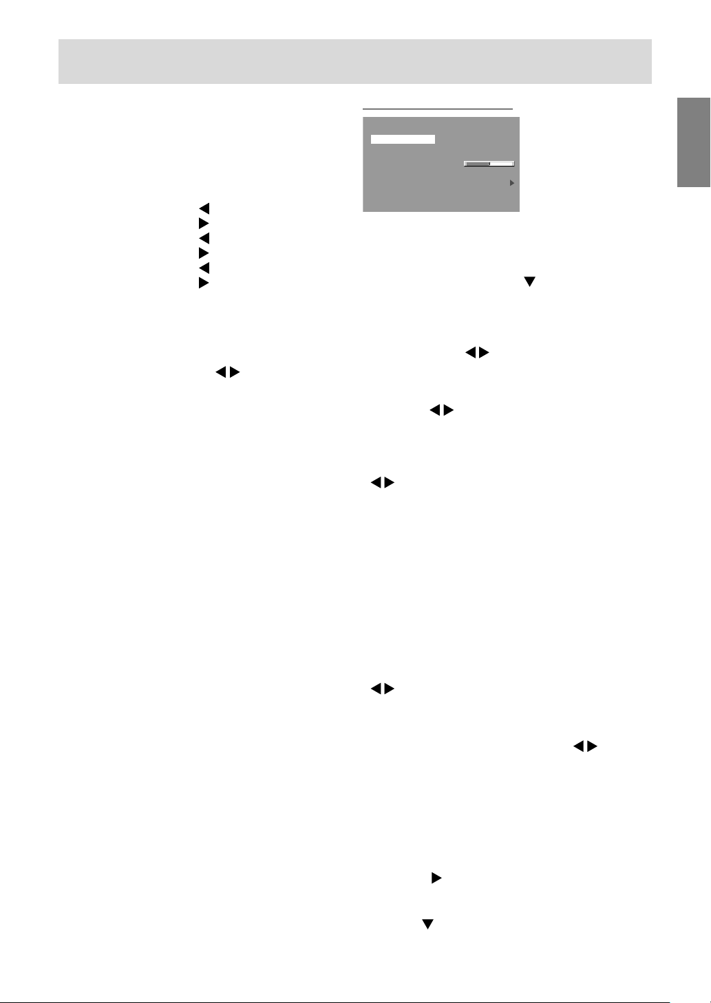
The ADJUSTMENT Menu will be displayed.
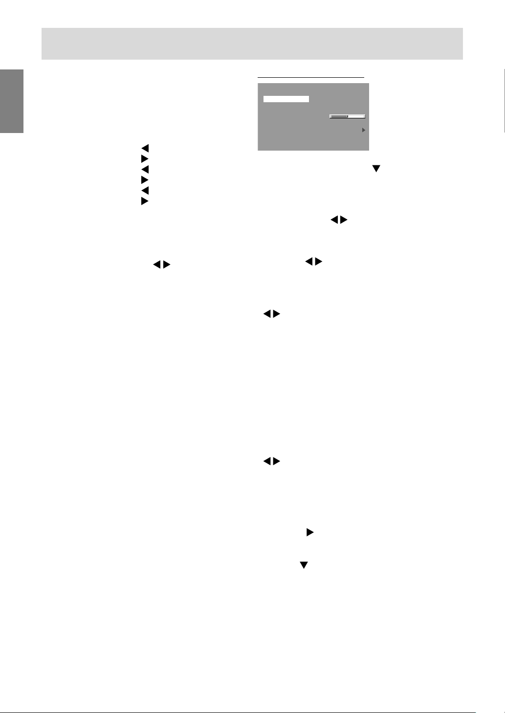
ADJUSTMENT
MANUAL AUTO
CLOCK 127
PHASE 0
H-POS 250
V-POS 48
INPUT-1 ANALOG
1600 x 1200 V:60Hz H:75.0kHz
-
-
-
-
+
+
+
+
2.Press the button.
The screen will become dark and [ADJUSTING]
will be displayed. After a few seconds the
ADJUSTMENT Menu will return. (The automatic
adjustment is now complete.)
3.Press the MENU button 5 times to make the OSD
(On Screen Display) Menu disappear.
Notes:
- In most cases automatic adjustment is sufficient.
- It may not be possible to achieve correct
adjustment with the first automatic adjustment. In
such a case, try repeating the automatic
adjustment 2 or 3 times.
- If necessary due to any of the following, manual
adjustments (p.21) can be performed after the
automatic adjustment:
- When further fine adjustment is needed.
- When [OUT OF ADJUST] is displayed. (When
the screen displays an entirely dark image, the
automatic screen adjustment may be disabled.
When making an automatic adjustment, be
sure to either use the Adjustment Pattern or try
displaying an image that makes the entire
screen very bright.)
- When the computer's video input signals are
Composite Sync or Sync on Green. (Automatic
adjustments may not be possible.)
- Automatic adjustment may not be achieved
correctly depending on what is displayed on the
screen - moving pictures or the MS-DOS prompt
etc.
Note:
- If your computer's display mode is set to 65K
colors, you may see the different color levels in
each color pattern or the gray scale may look
colored. (This is due to the specification of the
input signal and is not a malfunction.)
20
Page 21
Adjusting the screen display (With analog connection)
Manual screen adjustment
Adjustments can be made using OSD (On Screen
Display) Menu provided.
On Screen Display for adjustment
If you are using Windows, open the Adjustment
Pattern on the accompanying CD-ROM. (p.20)
If your system is not Windows, you can not use the
Adjustment Pattern. Therefore display an image
that makes the entire screen light and adjust it
through checking visually its actual tone.
This chapter provides the procedure how to adjust
the screen by using Adjustment Pattern (for
Windows).
How to adjust
1.Press the MENU button.
The ADJUSTMENT Menu will be displayed.
ADJUSTMENT
MANUAL AUTO
CLOCK 127
PHASE 0
H-POS 250
V-POS 48
INPUT-1 ANALOG
1600 x 1200 V:60Hz H:75.0kHz
-
-
-
-
At this point, relevant menu options can be
adjusted.
Each time the MENU button is pressed the next
menu is selected. (ADJUSTMENT GAIN
CONTROL COLOR CONTROL MODE
SELECT-1 MODE SELECT-2 OSD Menu
disappears)
Note:
- The OSD Menu automatically disappears
approximately 30 seconds after the last
command.
+
+
+
+
ADJUSTMENT Menu
ADJUSTMENT
MANUAL AUTO
CLOCK 127
PHASE 0
H-POS 250
V-POS 48
INPUT-1 ANALOG
1600 x 1200 V:60Hz H:75.0kHz
-
-
-
-
+
+
+
+
MANUAL: Individual menu options are manually
adjusted.
AUTO: Every menu option is automatically
adjusted.
Notes:
- Press the button to select [AUTO].
- To choose a menu option: / MODE button
- To go to the next menu: MENU button
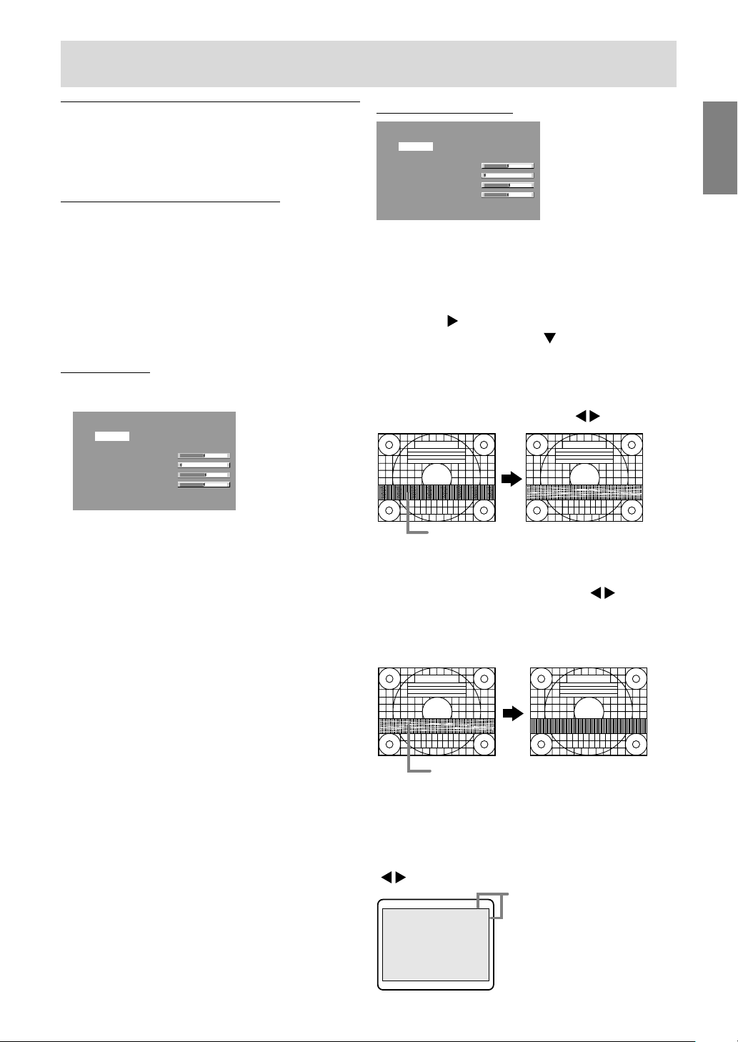
CLOCK
The figure below demonstrates how to adjust so that
vertical flicker noise is not emitted. (
buttons)
Vertical flicker noise
PHASE
The figure below demonstrates how to adjust so that
horizontal flicker noise is not emitted. ( buttons)
Note:
- Adjustments to [PHASE] should be made only
after [CLOCK] has been correctly set.
EnglishDeutschFrançaisItalianoEspañolEnglish
Horizontal flicker noise
H-POS (horizontal positioning) and V-POS
(vertical positioning)
To center the Adjustment Pattern within the
boundaries of the screen, adjust the left-right (HPOS) values and the up-down (V-POS) values.
( buttons)
Screen frame
Adjustment
Pattern
21
Page 22
Adjusting the screen display (With analog connection)
GAIN CONTROL Menu
GAIN CONTROL
MANUAL AUTO
BLACK LEVEL 50
CONTRAST 50
INPUT-1 ANALOG
1600 x 1200 V:60Hz H:75.0kHz
-
-
+
+
MANUAL: Individual menu options are manually
adjusted.
AUTO: Every menu option is automatically
adjusted using the Auto Gain Control*
function.
Notes:
- Press the
button to select [AUTO].
- To choose a menu option: / MODE button
- To go to the next menu: MENU button
* Auto Gain Control function
- The Auto Gain Control adjusts contrast and
black level based on the brightest and darkest
colors of the image displayed. If you are not
using the Adjustment Pattern it is necessary to
have black area and white area of at least 5 mm
x 5 mm on the screen. Adjustment may not be
possible without those areas.
- If the signal coming from the computer is
Composite Sync or Sync on Green, automatic
adjustment cannot be performed. Please
perform manual adjustment instead.
- If [OUT OF ADJUST] is displayed, perform
manual adjustment.
BLACK LEVEL
Total screen brightness can be adjusted while
watching the color pattern. ( buttons)
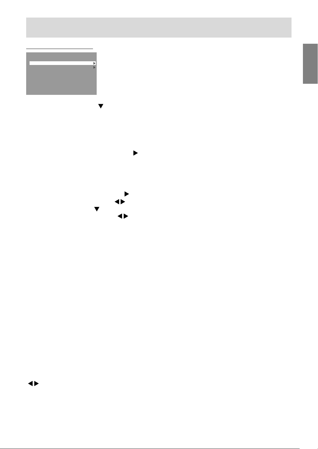
COLOR CONTROL Menu
COLOR CONTROL
WHITE BALANCE
GAMMA 0
INPUT-1 ANALOG
1600 x 1200 V:60Hz H:75.0kHz
-
+
Notes:
- To choose a menu option: / MODE button
- To go to the next menu: MENU button
WHITE BALANCE
After selecting [WHITE BALANCE], press the
button and display the adjustment menu.
WHITE BALANCE
COOL STD WARM USER
R-CONTRAST
G-CONTRAST
B-CONTRAST
...
<
>
MENU
OK
Notes:
- On settings other than [STD] not all gradations
can be displayed. To display all gradations, set
to [STD].
- If [DISPLAY MODE] is set to [sRGB] or [VIVID],
no other setting than [STD] can be selected.
- Use the buttons to select [COOL], [·], [STD],
[·], [WARM] or [USER].
- Selecting [USER] will display the setting values
for [R-CONTRAST], [G-CONTRAST] and
[B-CONTRAST], in order to make fine
adjustments.
- Use the / MODE button to select
[R-CONTRAST], [G-CONTRAST] and
[B-CONTRAST].
- When adjustment completes: MENU button
Color pattern
CONTRAST
While watching the color pattern, adjustments can
be made so that all gradations appear.
( buttons)
22
Page 23
Adjusting the screen display (With analog connection)
COOL ..... Color tone bluer than standard
• ...........Color tone slightly bluer than standard
STD ........Color tone standard setting
• ...........Color tone slightly redder than standard
WARM ....Color tone redder than standard
USER
R-CONTRAST ........
button for blue-green
button for red
G-CONTRAST ........
button for purple
button for green
B-CONTRAST .........
button for yellow
button for blue
GAMMA
Adjust so that dark and bright images are easy to
see. If the screen is dark and hard to see, increase
the numerical value. If it is bright and hard to see,
lower the numerical value. (
buttons)
- If [DISPLAY MODE] is set to [sRGB] or [VIVID],
[GAMMA] can not be set.
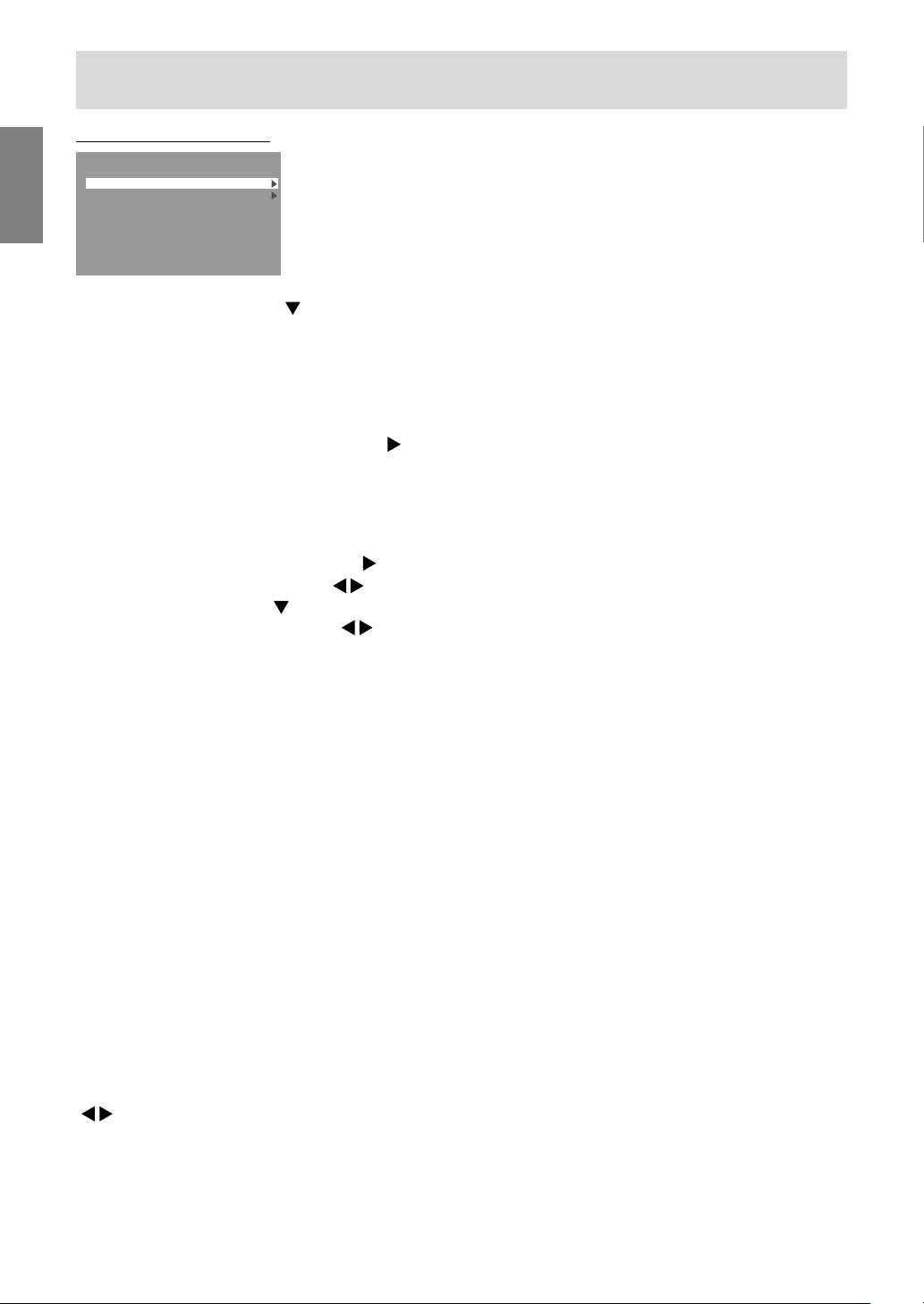
MODE SELECT-1 Menu
MODE SELECT-1
OSD H-POSITION
OSD V-POSITION
EXPAND
SCALING 3
400LINES 640 720
LANGUAGE
INPUT-1 ANALOG
1600 x 1200 V:60Hz H:75.0kHz
OFF ON1 ON2
-
+
Notes:
- Depending on the resolution of the input signal,
even if menu options can be selected, the
display may not change.
- To choose a menu option: / MODE button
- To go to the next menu: MENU button
OSD H-POSITION (OSD horizontal position)
The position of the OSD Menu can be moved to
the left and right. (
buttons)
OSD V-POSITION (OSD vertical position)
The position of the OSD Menu can be moved up
and down. (
buttons)
EXPAND (Screen expansion)
For display modes of less than 1600 x 1200 pixels,
the display can be expanded if desired.
(
buttons)
OFF: Expansion off
ON1: Using the fixed aspect ratio, the entire
screen is enlarged.
ON2: The entire screen is enlarged.
Note:
- If a resolution of 1600 x 1200 pixels cannot be
achieved even after expansion is attempted, the
screen's perimeter will display black. (This is not
a malfunction.)
EnglishDeutschFrançaisItalianoEspañolEnglish
SCALING (Level of scaling)
If [EXPAND] is set on [ON1] or [ON2], the
sharpness of the image can be adjusted.
buttons)
(
400 LINES (degree of resolution)
You can specify the horizontal resolution of a 400line screen when using US text, etc. (
buttons)
640: 640 x 400 dot mode
720: 720 x 400 dot mode (US text etc.)
Note:
- As the resolution input for other than 400 lines is
done automatically, there is no need to set it.
LANGUAGE
You can choose the language used in OSD Menu.
1.Press the
button.
The Language Selection Menu will be displayed
on the screen.
2.Use the / MODE button to choose a language.
3.Press the MENU button.
Language Selection Menu will disappear.
23
Page 24
Adjusting the screen display (With analog connection)
MODE SELECT-2 Menu
MODE SELECT-2
INFORMATION
OFF TIMER
INPUT-2
INPUT-1 ANALOG
1600 x 1200 V:60Hz H:75.0kHz
Notes:
- To choose a menu option: / MODE button
- To complete adjustment: MENU button
INFORMATION
A model name (MODEL), a serial no. (S/N), and
usage time (USAGE TIME) of the monitor can be
checked.
After selecting [INFORMATION], press the
button. (Checking done: MENU button)
OFF TIMER
Power is automatically shut off when the set time
elapses.
After selecting [OFF TIMER], press the
and set [ON]/[OFF] by pressing the buttons.
If selecting [ON], press the / MODE button and
set the shut-off time by pressing the buttons.
(Between 1 and 23 hours may be set, by the hour.)
(Setting done: MENU button)
- When [ON] is selected, the remaining time is
displayed in the upper right of the screen during
the last 5 minutes before the shut-off. (The
remaining time is displayed for approx. 5
seconds, on each minute.)
- To clear automatic shut-off temporarily, press the
power button between the display of remaining
time and the shut-off of power.
To subsequently turn the power off, press the
power button again. (When next turning on
power, power is again automatically shut off
when the set time elapses.)
- If the monitor is turned on when the [OFF TIMER]
is set to [ON], the set time appears on the display
for several seconds. (If there is no input signal,
[NO SIGNAL] is displayed.)
1LINE 2LINES
button
INPUT-2
Set [1LINE] when connecting digital or analog
signal cables to a DVI-I input terminal (INPUT-2)
on the display.
Set [2LINES] when connecting a 2-input cable.
( buttons)
- If the connections and settings are not correctly
set, the screen will not be correctly displayed.
24
Page 25
Adjusting the screen display (With digital connection)
Adjustments can be made using OSD (On Screen
Display) Menu provided.
On Screen Display for adjustment
If you are using Windows, open the Adjustment
Pattern on the accompanying CD-ROM. (p.20)
If your system is not Windows, you can not use the
Adjustment Pattern. Therefore display an image
that makes the entire screen light and adjust it
through checking visually its actual tone.
How to adjust
1.Press the MENU button 3 times.
The COLOR CONTROL Menu will be displayed.
COLOR CONTROL
WHITE BALANCE
GAMMA 0
INPUT-2 DIGITAL
1600 x 1200 V:60Hz H:75.0kHz
-
+
At this point, relevant menu options can be
adjusted.
Each time the MENU button is pressed the next
menu is selected. (COLOR CONTROL MODE
SELECT-1 MODE SELECT-2 OSD Menu
disappears)
Notes:
- Like when making an analog connection, the
ADJUSTMENT Menu and the GAIN CONTROL
Menu are displayed. However, you don't need to
adjust these items.
- The OSD Menu automatically disappears
approximately 30 seconds after the last
command.
COLOR CONTROL Menu
COLOR CONTROL
WHITE BALANCE
GAMMA 0
INPUT-2 DIGITAL
1600 x 1200 V:60Hz H:75.0kHz
-
+
Notes:
- To choose a menu option: / MODE button
- To go to the next menu: MENU button
WHITE BALANCE
After selecting [WHITE BALANCE], press the
button and display the adjustment menu.
WHITE BALANCE
COOL STD WARM USER
R-CONTRAST
G-CONTRAST
B-CONTRAST
...
<
>
MENU
OK
Notes:
- On settings other than [STD] not all gradations
can be displayed. To display all gradations, set
to [STD].
- If [DISPLAY MODE] is set to [sRGB] or [VIVID],
no other setting than [STD] can be selected.
- Use the buttons to select [COOL], [·], [STD],
[·], [WARM] or [USER].
- Selecting [USER] will display the setting values
for [R-CONTRAST], [G-CONTRAST] and
[B-CONTRAST], in order to make fine
adjustments.
- Use the / MODE button to select
[R-CONTRAST], [G-CONTRAST] and
[B-CONTRAST].
- When adjustment completes: MENU button
EnglishDeutschFrançaisItalianoEspañolEnglish
25
Page 26
Adjusting the screen display (With digital connection)
COOL ..... Color tone bluer than standard
• ...........Color tone slightly bluer than standard
STD ........Color tone standard setting
• ...........Color tone slightly redder than standard
WARM ....Color tone redder than standard
USER
R-CONTRAST ........
button for blue-green
button for red
G-CONTRAST ........
button for purple
button for green
B-CONTRAST.........
button for yellow
button for blue
GAMMA
Adjust so that dark and bright images are easy to
see. If the screen is dark and hard to see, increase
the numerical value. If it is bright and hard to see,
lower the numerical value. (
buttons)
- If [DISPLAY MODE] is set to [sRGB] or [VIVID],
[GAMMA] can not be set.
MODE SELECT-1 Menu
MODE SELECT-1
OSD H-POSITION
OSD V-POSITION
EXPAND
SCALING 3
400LINES 640 720
LANGUAGE
INPUT-2 DIGITAL
1600 x 1200 V:60Hz H:75.0kHz
OFF ON1 ON2
-
+
Notes:
- To choose a menu option: / MODE button
- To go to the next menu: MENU button
OSD H-POSITION (OSD horizontal position)
The position of the OSD Menu can be moved to
the left and right. (
buttons)
OSD V-POSITION (OSD vertical position)
The position of the OSD Menu can be moved up
and down. (
buttons)
EXPAND (Screen expansion)
For display modes of less than 1600 x 1200 pixels,
the display can be expanded if desired.
buttons)
(
OFF: Expansion off
ON1: Using the fixed aspect ratio, the entire
screen is enlarged.
ON2: The entire screen is enlarged.
Note:
- If a resolution of 1600 x 1200 pixels cannot be
achieved even after expansion is attempted, the
screen's perimeter will display black. (This is not
a malfunction.)
SCALING (Level of scaling)
If [EXPAND] is set on [ON1] or [ON2], the
sharpness of the image can be adjusted.
buttons)
(
400 LINES (degree of resolution)
No setting is required.
LANGUAGE
You can choose the language used in OSD Menu.
1.Press the
button.
The Language Selection Menu will be displayed
on the screen.
2.Use the / MODE button to choose a language.
3.Press the MENU button.
Language Selection Menu will disappear.
26
Page 27
Adjusting the screen display (With digital connection)
MODE SELECT-2 Menu
MODE SELECT-2
INFORMATION
OFF TIMER
INPUT-2
INPUT-2 DIGITAL
1600 x 1200 V:60Hz H:75.0kHz
Notes:
- To choose a menu option: / MODE button
- To complete adjustment: MENU button
INFORMATION
A model name (MODEL), a serial no. (S/N), and
usage time (USAGE TIME) of the monitor can be
checked.
After selecting [INFORMATION], press the
button. (Checking done: MENU button)
OFF TIMER
Power is automatically shut off when the set time
elapses.
After selecting [OFF TIMER], press the
and set [ON]/[OFF] by pressing the buttons.
If selecting [ON], press the / MODE button and
set the shut-off time by pressing the buttons.
(Between 1 and 23 hours may be set, by the hour.)
(Setting done: MENU button)
- When [ON] is selected, the remaining time is
displayed in the upper right of the screen during
the last 5 minutes before the shut-off. (The
remaining time is displayed for approx. 5
seconds, on each minute.)
- To clear automatic shut-off temporarily, press the
power button between the display of remaining
time and the shut-off of power.
To subsequently turn the power off, press the
power button again. (When next turning on
power, power is again automatically shut off
when the set time elapses.)
- If the monitor is turned on when the [OFF TIMER]
is set to [ON], the set time appears on the display
for several seconds. (If there is no input signal,
[NO SIGNAL] is displayed.)
1LINE 2LINES
button
EnglishDeutschFrançaisItalianoEspañolEnglish
INPUT-2
Set [1LINE] when connecting digital or analog
signal cables to a DVI-I input terminal (INPUT-2)
on the display.
Set [2LINES] when connecting a 2-input cable.
( buttons)
- If the connections and settings are not correctly
set, the screen will not be correctly displayed.
27
Page 28
Monitor care
Monitor care
Always remove the plug from the AC outlet when
cleaning the monitor.
Cabinet and control panel section
Use a soft dry cloth to lightly wipe away any grime
from the cabinet and control panel.
If they are very dirty, apply neutral detergent to a
dampened soft cloth, wring it out well and wipe
away grime.
LCD panel section
Use a soft dry cloth to lightly wipe away dirt and
dust from the surface of the LCD panel. (A soft
cloth such as gauze or that used for lens cleaning
is suitable.)
CAUTION!
- Never use thinner, benzine, alcohol, glass
cleaner, etc, as this could lead to color change or
change in shape.
- Never scratch the monitor with anything hard or
apply strong pressure as this could leave marks
or result in malfunction.
Storage
If the monitor will not be used for a long period of
time, be sure to remove the power plug from the
AC outlet.
CAUTION!
- Do not leave the monitor in contact with rubber or
plastic items for long periods of time as this could
lead to color change or change in shape.
Troubleshooting
If you think the monitor may be faulty, please
check the following points before taking it to be
repaired.
If afterwards it still does not work, please contact
the shop where you purchased the monitor or your
nearest Sharp authorized Service Center.
The monitor's fluorescent tubes have a limited
life span.
- If the screen darkens, persistently flickers or
does not light up, it may be necessary to
replace the fluorescent tube unit. Please
inquire at the shop where you purchased the
monitor or your nearest Sharp authorized
Service Center. (Never attempt this
replacement on your own.)
- In the initial period of use, due to the
characteristics of fluorescent tubes the screen
may flicker. (This is not a malfunction.) Should
this happen, check by first turning off the
power, then turning it on again.
No image appears on the screen (power LED is
not lit).
- Is the power cord connected properly? (p.15)
No image appears on the screen (power LED is lit).
- Is the computer connected properly? (p.14)
- Is the computer turned on?
- Is the signal's input terminal switched to the
correct one? (p.16)
- Is [INPUT-2] set correctly in the MODE SELECT-2
Menu? (p.24, 27)
- Does the computer's signal timing correspond to
monitor specifications? (p.31)
- Is the computer in power-saving mode?
The image appears distorted.
- Does the computer's signal timing correspond to
monitor specifications? (p.31)
- If you are using the analog signal, perform
automatic screen adjustment. (p.20)
- If you can change the refresh rate on the
computer you are using, change the value to a
lower frequency. (p.31)
Control buttons do not work.
- Is the adjustment lock on? (p.18)
28
Page 29

Monitor care
Information for customers on
environmentally friendly disposal of
this SHARP product
If this product cannot be used any more, it should
be given away and disposed of in a legally correct
and environmentally sound way.
DO NOT DISPOSE OF THIS PRODUCT WITH
YOUR HOUSEHOLD WASTE OR MIXED WITH
OTHER WASTES ! YOU MIGHT ENDANGER THE
ENVIRONMENT !
Sharp Corporation is committed to protecting the
environment and conserving energy. Our goal is to
minimize the environmental impact of our products
by continually implementing and improving
product technologies, designs, and customer
information aimed at environmental conservation.
(1) For our customers in United Kingdom,
Germany, France, and Italy
Please contact your local authorities for
collection and recycling facilities, or contact a
recycling service company, which is licensed
for the recycling of electronic equipment.
SHARP recommends the recycling services of
MIREC, the General information on MIREC can
be obtained from http://www.mirec.com/.
MIREC services have to be paid for by the last
owner of the electronic equipment in question.
EnglishDeutschFrançaisItalianoEspañolEnglish
(2) For our customers in the USA
This product utilizes tin-lead solder, and a
fluorescent lamp containing a small amount of
mercury. Disposal of these materials may be
regulated due to environmental considerations.
For collection and recycling information,
please contact your local authorities or
the Electronics Industries Alliance:
http://www.eiae.org
(3) For our customers in Japan
Call toll free number 0120-845-530 for
recycling Information.
29
Page 30
Specifications
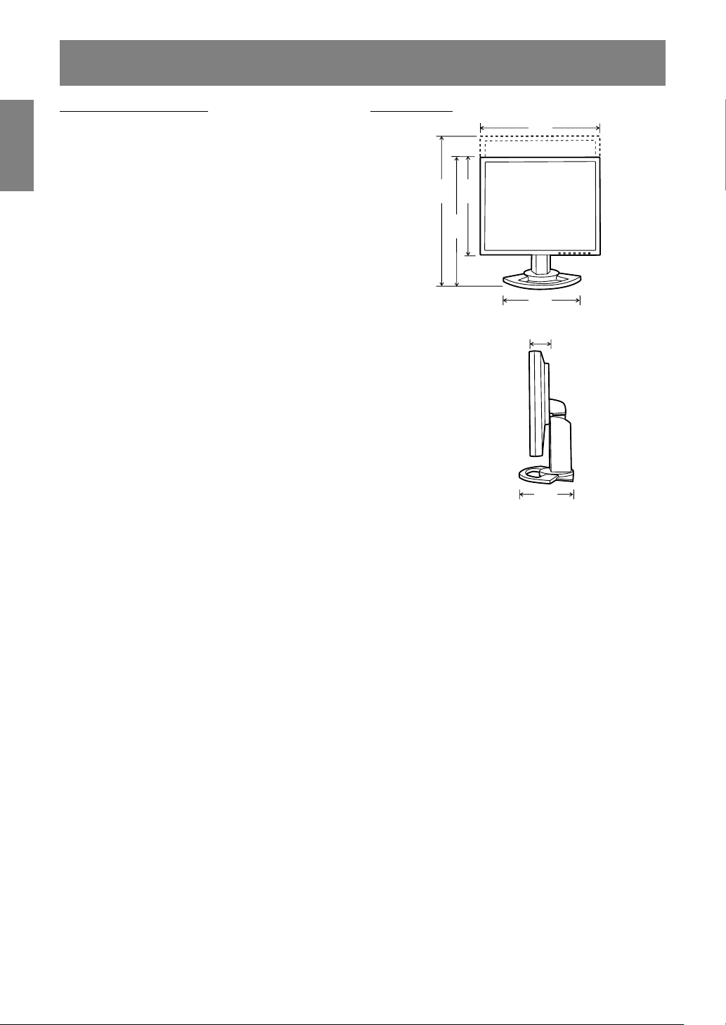
450
228
438
348
498
310
62
Product specifications
Model name
LL-T2015-H (Ivory)/LL-T2015-B (Black)
LCD display
51 cm measured diagonally TFT LCD module
Resolution (max.)
UXGA 1600 x 1200 pixels
Displayable colors (max.)
Approx. 16.77 million colors (8 bit)
Brightness (max.)
250 cd/m
2
Dot pitch
0.255(H) x 0.255(V) mm
Contrast ratio
400:1
Angle of visibility
Left-right 176°; Up-down 176°
>
(contrast ratio
=
10)
Screen display size
Horizontal 408 mm x Vertical 306 mm
Video signal
Analog: Analog RGB (0.7 Vp-p) [75 :]
Digital: DVI standard based on 1.0
Sync signal
Separate Sync (TTL level: +/-), Sync on
Green, Composite Sync (TTL level: +/-)
Expansion compensation
Digital scaling
Enlarging VGA/SVGA/XGA/SXGA etc. with a
compensation process. (no enlarging, based on a
fixed aspect ratio, and enlarging to full screen
size.)
Plug & Play
VESA DDC2B compatible
Power management
VESA: based on DPMS
DVI: based on DMPM
Input signal terminal
Analog: 15 pin mini D-sub (3 rows)
Digital/Analog: 29 pin DVI-I
Height adjustment
Adjustment range: approx. 60 mm
Screen tilt
Upward approx. 0 - 30°; downward approx. 0 - 5°
Screen swivel
Approx. 90° from left through right
Power supply
AC100 - 240 V, 50/60 Hz
Temperature of operating environment
5 - 35°C
Power consumption
53 W maximum, 4 W when in power-saving mode
Dimensions (W x D x H) (Units: mm)
Approx. 450 x 228 x 438 - 498
Weight
Approx. 9.8 kg
Display area only, approx. 6.2 kg
Dimensions (Units: mm)
- Analog signal cable: approx. 2.0 m
- Digital signal cable: approx. 2.0 m
- Analog signal cable, NL-C02E (purchased
separately): approx. 2.0 m
- 2-input cable, NL-C03J (purchased
separately): approx. 0.25 m
Note:
- As a part of our policy of continuous
improvement, SHARP reserves the right to make
design and specification changes for product
improvement without prior notice. The
performance specification figures indicated are
nominal values of production units. There may
be some deviations from these values in
individual units.
30
Page 31

Specifications
Relevant signal timings (analog)
60Hz
72Hz
75Hz
85Hz
85Hz
85Hz
56Hz
60Hz
72Hz
75Hz
85Hz
60Hz
70Hz
75Hz
85Hz
75Hz
60Hz
60Hz
75Hz
85Hz
60Hz
70Hz
75Hz
75Hz
60Hz
75Hz
60Hz
60Hz
66Hz
70Hz
66Hz
76Hz
66Hz
Dot
frequency
25.175MHz
31.5MHz
31.5MHz
36.0MHz
31.5MHz
35.5MHz
36.0MHz
40.0MHz
50.0MHz
49.5MHz
56.25MHz
65.0MHz
75.0MHz
78.75MHz
94.5MHz
108.0MHz
108.0MHz
108.0MHz
135.0MHz
157.5MHz
162.0MHz
28.3MHz
30.2MHz
57.3MHz
80.0MHz
100.0MHz
108.0MHz
135.0MHz
162.0MHz
64.13MHz
70.4MHz
74.25MHz
94.88MHz
108.23MHz
117.01MHz
134.99MHz
135.76MHz
Display mode
VESA
US text
Power
Macintosh
series
Sun Ultra
series
640x480
640x400
720x400
800x600
1024x768
1152
x864
1280
x960
1280x1024
1600x1200
720x400
640x480
832x624
1024
x768
1152
x870
1280x1024
1600x1200
1024
x768
1152
x900
1280x1024
1600x1000
Hsync
31.5kHz
37.9kHz
37.5kHz
43.3kHz
37.9kHz
37.9kHz
35.1kHz
37.9kHz
48.1kHz
46.9kHz
53.7kHz
48.4kHz
56.5kHz
60.0kHz
68.7kHz
67.5kHz
60.0kHz
64.0kHz
80.0kHz
91.1kHz
75.0kHz
31.5kHz
35.0kHz
49.7kHz
60.2kHz
68.7kHz
64.0kHz
80.0kHz
75.0kHz
48.3kHz
53.6kHz
56.6kHz
61.8kHz
71.8kHz
71.7kHz
81.1kHz
68.6kHz
Vsync
66.7Hz
74.6Hz
76.2Hz
67.2Hz
- Recommended resolution is 1600 x 1200.
- All are compliant only with non-interlaced.
- Frequencies for Power Macintosh and the Sun
Ultra series are reference values. To connect,
another adapter (commercially available) may be
required.
- If the monitor is receiving timing signals that are
not compatible, [OUT OF TIMING] will appear.
Follow your computer's instruction manual to set
the timing so that it is compatible with the
monitor.
- If the monitor is not receiving any signal (synch
signal), [NO SIGNAL] will appear.
Relevant signal timings (digital)
Display mode
VESA
US text
640x480
800x600
1024x768
1152x864
1280x960
1280x1024
1600x1200
720x400
Hsync
31.5kHz
37.9kHz
37.5kHz
37.9kHz
48.1kHz
46.9kHz
48.4kHz
56.5kHz
60.0kHz
67.5kHz
60.0kHz
64.0kHz
75.0kHz
31.5kHz
Vsync
60Hz
72Hz
75Hz
60Hz
72Hz
75Hz
60Hz
70Hz
75Hz
75Hz
60Hz
60Hz
60Hz
70Hz
Dot
frequency
25.175MHz
31.5MHz
31.5MHz
40.0MHz
50.0MHz
49.5MHz
65.0MHz
75.0MHz
78.75MHz
108.0MHz
108.0MHz
108.0MHz
162.0MHz
28.3MHz
- Recommended resolution is 1600 x 1200.
- All are compliant only with non-interlaced.
- A computer with an output terminal conforming to
DVI (DVI-D24 pin or DVI-I29 pin) and with UXGA
output capability can be connected here.
(Depending on the type of computer to be
connected, the display may not work correctly.)
- If the monitor is receiving timing signals that are
not compatible, [OUT OF TIMING] will appear.
Follow your computer's instruction manual to set
the timing so that it is compatible with the
monitor.
- If the monitor is not receiving any signal (synch
signal), [NO SIGNAL] will appear.
EnglishDeutschFrançaisItalianoEspañolEnglish
31
Page 32

Specifications
The analog RGB input connector pin
(Mini D-sub connector with 15 pins)
5 1234
10
15 11121314
6789
No. Function
1 Red video signal input
2 Green video signal input
3 Blue video signal input
4 GND
5 GND
6 For red video signal GND
7 For green video signal GND
8 For blue video signal GND
9 +5V
10 GND
11 GND
12 DDC data
13 For Hsync signal input
14 For Vsync signal input
15 DDC clock
The DVI-I input connector pin
(DVI-I connector with 29 pins)
C2
C1
1 765432 8
9
17 23
No. Function No. Function
1 TMDS data 2- 16 Hot plug detection
2 TMDS data 2+ 17 TMDS data 0-
3 TMDS data 2/4 shield 18 TMDS data 0+
4 N.C. 19 TMDS data 0/5 shield
5 N.C. 20 N.C.
6 DDC clock 21 N.C.
7 DDC data 22 TMDS clock shield
Analog vertically
8 23 TMDS clock +
synchronised signal
9 TMDS data 1- 24 TMDS clock -
10 TMDS data 1+ C1
11 TMDS data 1/3 shield C2
12 N.C. C3
13 N.C. C4
14 +5V C5 Analog GND
15 GND
151413121110 16
21201918 24
22
C5
C4
C3
Analog red image signal
Analog green image signal
Analog blue image signal
Analog horizontally
synchronised signal
Power management
The monitor is based on the VESA DPMS and the
DVI DMPM standards.
To activate the monitor's power management
function, both the video card and the computer
must conform to the VESA DPMS standard and the
DVI DMPM standard.
DPMS: Display Power Management Signalling
DPMS mode Screen
ON Display on 53 W Yes Yes
STANDBY No Yes
SUSPEND Display off 4 W Yes No
OFF No No
Power
consumption
H-sync V-sync
DMPM: Digital Monitor Power Management
DMPM mode Screen
ON Display on 53 W
OF F Display off 4 W
Power
consumption
DDC (Plug & Play)
This monitor supports the VESA DDC (Display
Data Channel) standard.
DDC is a signal standard for carrying out Plug &
Play functions on the monitor or PC. It transfers
information such as degree of resolution between
the monitor and PC. You can use this function if
your PC is DDC compliant and if it is set so that it
can detect the Plug & Play monitor.
There are many varieties of DDC due to the
differences between systems. This monitor works
with DDC2B.
32
Page 33

Installing set-up information and the ICC profile (For Windows)
Depending on the type of computer or OS, you
may need to install the monitor set-up information
on your system. If so, follow the steps below to
install the monitor set-up information. (Depending
on the type of computer or OS, command names
and methods may differ. Please follow the
computer's own operation manual while reading
this.)
About the ICC profile
An ICC (International Color Consortium) profile is
a file that describes the color reproduction
characteristics of the LCD monitor. Using an
application compatible with an ICC profile, highly
accurate color reproduction can be realized.
- Windows 98/2000/Me/XP all use the ICC profile.
- When installing Windows 98/2000/Me/XP set-up
information (described below), the ICC profile is
also installed. If you would like to install the ICC
profile only, please refer to Installing the ICC
profile on page 35.
- When using the ICC profile, set as follows:
- [DISPLAY MODE] [WHITE BALANCE]: [STD]
- [GAMMA]: [0]
For Windows 95
Installing monitor set-up information into Windows
95.
This explanation assumes that the CD-ROM drive
is "D" drive.
1. Load the accessory CD-ROM into the CD-ROM
drive of the computer.
2. Click on the [Start] button. From [Settings],
choose [Control Panel].
3. Double click on [Display].
4. Click on [Settings], [Advanced Properties], and
[Monitor], then [Change].
5. Click on [Have disk], confirm that [Copy
manufacturer's files from:] is [D:] then click
[OK].
6. Confirm that the monitor details are selected,
and click [OK].
7. Check that the monitor details are displayed,
then click [Apply].
8. Click [OK], and close the window.
For Windows 98
Installing monitor set-up information into Windows
98, and setting the monitor's ICC profile as a
predetermined value.
This explanation assumes that the CD-ROM drive
is "D" drive.
If the "Add New Hardware Wizard" has appeared:
1. Load the accessory CD-ROM into the CD-ROM
drive of the computer.
2. Click [Next].
3. Check [Display a list of all the drivers in a
specific location, so you can select the driver
you want.], then click [Next].
4. When [Models] is displayed, click on [Have
disk], confirm that [Copy manufacturer's files
from:] is [D:], and click [OK].
5. Confirm that the monitor details are selected,
then click [Next], [Next], and [Finish]. If the "Add
New Hardware Wizard" appears, repeat the
installation commands beginning from 2 above.
If the "Add New Hardware Wizard" has not
appeared:
1. Load the accessory CD-ROM into the CD-ROM
drive of the computer.
2. Click on the [Start] button. From [Settings],
choose [Control Panel].
3. Double click on [Display].
4. Click on [Settings], [Advanced] and [Monitor].
5. In [Options], check [Automatically detect Plug &
Play monitors] and click on [Change].
6. Click [Next].
7. Click on [Display a list of all the drivers in a
specific location, so you can select the driver
you want.], then click [Next].
8. When [Models] is displayed, click on [Have
disk], confirm that [Copy manufacturer's files
from:] is [D:], and click [OK].
9. Confirm that the monitor details are selected,
then click [Next], [Next], and [Finish].
10. Check that the monitor details are displayed,
then click [Apply].
11. Click [OK], and close the window.
EnglishDeutschFrançaisItalianoEspañolEnglish
33
Page 34

Installing set-up information and the ICC profile (For Windows)
For Windows 2000
Installing monitor set-up information into Windows
2000, and setting the monitor's ICC profile as a
predetermined value.
This explanation assumes that the CD-ROM drive
is "D" drive.
1. Load the accessory CD-ROM into the CD-ROM
drive of the computer.
2. Click on the [Start] button. From [Settings],
choose [Control Panel].
3. Double click on [Display].
4. Click on [Settings], [Advanced] and [Monitor].
5. Click on [Properties], [Driver] and [Update
Driver].
6. When [Upgrade Device Driver Wizard] appears,
click [Next].
7. Check [Display a list of the known drivers for
this device so that I can choose a specific
driver] and click [Next].
8. When [Models] is displayed, click on [Have
disk], confirm that [Copy manufacturer's files
from:] is [D:], and click [OK].
9. Select the monitor from the list displayed and
click [Next].
10. Click [Next], confirm that the monitor's name
appears on the screen, and click [Finish]. If
[The Digital Signature Not Found] appears, click
[Yes].
11. Click on [Close].
12. Click [OK], and close the window.
For Windows Me
Installing monitor set-up information into Windows
Me, and setting the monitor's ICC profile as a
predetermined value.
This explanation assumes that the CD-ROM drive
is "D" drive.
If the "Add New Hardware Wizard" has appeared:
1. Load the accessory CD-ROM into the CD-ROM
drive of the computer.
2. Check [Specify the location of the driver
[Advanced]] and click [Next].
3. Check [Display a list of all the drivers in a
specific location, so you can select the driver
you want.], then click [Next].
4. When [Models] is displayed, click on [Have
disk], confirm that [Copy manufacturer's files
from:] is [D:], and click [OK].
5. Select the monitor details from the list, then
click [Next], [Next], and [Finish]. If the "Add New
Hardware Wizard" appears, repeat the
installation commands beginning from 2 above.
If the "Add New Hardware Wizard" has not
appeared:
1. Load the accessory CD-ROM into the CD-ROM
drive of the computer.
2. Click on the [Start] button. From [Settings],
choose [Control Panel].
3. Double click on [Display].
4. Click on [Settings], [Advanced] and [Monitor].
5. In [Options], check [Automatically detect Plug &
Play monitors] and click on [Change].
6. Check [Specify the location of the driver
[Advanced]] and click [Next].
7. Check [Display a list of all the drivers in a
specific location, so you can select the driver
you want.] and click [Next].
8. When [Models] is displayed, click on [Have
disk], confirm that [Copy manufacturer's files
from:] is [D:], and click [OK].
9. Select the monitor details, then click [Next],
[Next], and [Finish].
10. Check that the monitor details are displayed,
then click [Apply].
11. Click [OK], and close the window.
34
Page 35

Installing set-up information and the ICC profile (For Windows)
For Windows XP
Installing monitor set-up information into Windows
XP, and setting the monitor's ICC profile as a
predetermined value.
This explanation assumes that the CD-ROM drive
is "D" drive.
1. Load the accessory CD-ROM into the CD-ROM
drive of the computer.
2. Click on the [Start] button. Choose [Control
Panel].
3. Switch to "Classic View".
4. Double click on [Display].
5. Click on [Settings], [Advanced] and [Monitor].
6. Click on [Properties], [Driver] and [Update
Driver].
7. When [Hardware Update Wizard] appears,
check [Install from a list or specific location
[Advanced]] and click [Next].
8. Check [Don't search. I will choose the driver to
install.] and click [Next].
9. Click on [Have Disk], confirm that [Copy
manufacturer's files from:] is [D:], and click [OK].
10. Select the monitor from the list displayed and
click [Next].
If [has not passed Windows Logo testing...]
appears, click [Continue Anyway].
11. Confirm that the monitor's name appears on the
screen.
12. Click on [Finish].
13. Click on [Close].
14. Click [OK], and close the window.
Installing the ICC profile
Installing the monitor's ICC profile. (If the set-up
information has already been installed, so too has
the profile, and there is no need to install it.)
This explanation assumes that the CD-ROM drive
is "D" drive.
1. Load the accessory CD-ROM into the CD-ROM
drive of the computer.
2. Click on the [Start] button. From [Settings],
choose [Control Panel].
3. Double click on [Display].
4. Click on [Settings] and [Advanced].
5. Click on [General] and from [Compatibility]
select [Apply the new display setting without
restarting], then click on [Color Management].
6. Click [Add], and select CD-ROM as the file
location.
7. Choose the color profile that you would like to
install, and click on [Add].
8. Choose the profile and click on [Set As Default].
9. Click [OK], and close the window.
- When using the ICC profile, set as follows:
- [DISPLAY MODE] [WHITE BALANCE]: [STD]
- [GAMMA]: [0]
EnglishDeutschFrançaisItalianoEspañolEnglish
35
Page 36

Information about the ColorSync profile (For MacOS)
About the ColorSync profile
ColorSync is Apple Computer's color management
system and enables color reproduction
characteristics to be realized when used with a
compatible application. A ColorSync profile
describes the color characteristics of the LCD
monitor.
Notes:
- This monitor's ColorSync profile works with
MacOS 8.5 or above.
- When using the ColorSync profile, set as
follows:
- [DISPLAY MODE] [WHITE BALANCE]: [STD]
- [GAMMA]: [0]
Setting up the ColorSync profile
Notes:
- It is necessary to have PC Exchange or File
Exchange installed in your system.
- Depending on the type of computer or OS,
command names and methods may differ. Please
follow the computer's own operation manual
while reading this.
1.Load the accessory CD-ROM into the CD-ROM
drive of the computer.
2.Copy the profile to be used from the CD-ROM to
the ColorSync profile folder in the system folder.
3.Using the ColorSync on the control panel,
choose the profile to be used.
36
Page 37

Instructions for attaching a VESA-compliant arm
An arm or stand based on the VESA standard
(commercially available) can be attached to the
monitor.
Procurement of the arm or stand is at the
customer's discretion.
Arms or stands able to be used
Attachments must satisfy the following:
- Compatible with the VESA standard.
- Have a gap of 100 mm x 100 mm between the
screw holes on the section to be attached.
- Not be likely to fall off or break off after being
attached to the monitor.
How to attach the arm or stand
- Be careful not to over bend the cable or add
extension cords as this could lead to
malfunction.
- While following these instructions, please also
refer to the installation instructions in the
operation manual included with the arm or stand.
1.Remove the cable.
2.Spread out a soft cloth on a suitable horizontal
surface.
3.Being careful not to damage the monitor, gently
lay the monitor on it display-side down.
Notes:
- The stand is specially made for use with this
monitor. Once having removed the stand, never
attempt to attach it to another device.
- Once having removed the screws, store them
together with the stand and if the stand is ever
re-attached be sure to use the original screws.
Using different screws could lead to a
malfunction.
CAUTION!
Do not disassemble the stand. Parts may
spring out and cause injury.
5.Attach the arm to the monitor with the four
screws.
EnglishDeutschFrançaisItalianoEspañolEnglish
CAUTION!
Securely grasp both the display and
stand, and gently tip over. When the
monitor is inclined, the stand may
suddenly pop out and cause injury.
4.Remove the four screws and then remove the
stand from the monitor.
Note:
- The screws used to attach the arm should be M4
screws with a length of 6 - 8 mm protruding from
the surface to be attached. Using different
screws could cause the monitor to fall off or to be
internally damaged.
6 - 8 mm
Screw used to attach arm
Arm
Part of monitor to which arm is
attached
37
Page 38

38
Page 39

Inhaltsverzeichnis
Tipp und Sicherheitsvorkehrungen . . . . . . . . . . . . . . . . . . . . . . . . . . . . . . . . . . . . . . . . . . . . . . . . . . . . . . 40
Produktbeschreibung . . . . . . . . . . . . . . . . . . . . . . . . . . . . . . . . . . . . . . . . . . . . . . . . . . . . . . . . . . . . . . . . 41
Höheneinstellung, Winkeleinstellung . . . . . . . . . . . . . . . . . . . . . . . . . . . . . . . . . . . . . . . . . . . . . . . . . . . . 42
Anschließen des Monitors und Ein- und Ausschalten des Monitors . . . . . . . . . . . . . . . . . . . . . . . . . . . . 43
Verbinden des Monitors mit einem Computer . . . . . . . . . . . . . . . . . . . . . . . . . . . . . . . . . . . . . . . . . . 44
Anschließen des Monitors an eine Stromquelle . . . . . . . . . . . . . . . . . . . . . . . . . . . . . . . . . . . . . . . . . 45
Einschalten des Monitors . . . . . . . . . . . . . . . . . . . . . . . . . . . . . . . . . . . . . . . . . . . . . . . . . . . . . . . . . . . 46
Umschalten zwischen Eingangsanschlüssen . . . . . . . . . . . . . . . . . . . . . . . . . . . . . . . . . . . . . . . . . . 47
Ausschalten des Monitors . . . . . . . . . . . . . . . . . . . . . . . . . . . . . . . . . . . . . . . . . . . . . . . . . . . . . . . . . . 47
Einstellen der Bildschirmanzeige . . . . . . . . . . . . . . . . . . . . . . . . . . . . . . . . . . . . . . . . . . . . . . . . . . . . . . . 48
Zurücksetzen der Einstellungen . . . . . . . . . . . . . . . . . . . . . . . . . . . . . . . . . . . . . . . . . . . . . . . . . . . . . 48
Einstellsperrfunktion. . . . . . . . . . . . . . . . . . . . . . . . . . . . . . . . . . . . . . . . . . . . . . . . . . . . . . . . . . . . . . . 48
Einstellen der Hintergrundbeleuchtung . . . . . . . . . . . . . . . . . . . . . . . . . . . . . . . . . . . . . . . . . . . . . . . 48
Einstellen des Displaymodus . . . . . . . . . . . . . . . . . . . . . . . . . . . . . . . . . . . . . . . . . . . . . . . . . . . . . . . 49
Überprüfen der Geräteinformationen . . . . . . . . . . . . . . . . . . . . . . . . . . . . . . . . . . . . . . . . . . . . . . . . . 49
Einstellen der Bildschirmanzeige (bei analogem Anschluss) . . . . . . . . . . . . . . . . . . . . . . . . . . . . . . . . . 50
Automatische Bildschirmeinstellung . . . . . . . . . . . . . . . . . . . . . . . . . . . . . . . . . . . . . . . . . . . . . . . . . . 50
Manuelle Bildschirmeinstellung . . . . . . . . . . . . . . . . . . . . . . . . . . . . . . . . . . . . . . . . . . . . . . . . . . . . . 51
Einstellen der Bildschirmanzeige (bei digitalem Anschluss) . . . . . . . . . . . . . . . . . . . . . . . . . . . . . . . . . . 55
Pflege des Monitors . . . . . . . . . . . . . . . . . . . . . . . . . . . . . . . . . . . . . . . . . . . . . . . . . . . . . . . . . . . . . . . . . . 58
Pflege des Monitors . . . . . . . . . . . . . . . . . . . . . . . . . . . . . . . . . . . . . . . . . . . . . . . . . . . . . . . . . . . . . . . 58
Lagerung . . . . . . . . . . . . . . . . . . . . . . . . . . . . . . . . . . . . . . . . . . . . . . . . . . . . . . . . . . . . . . . . . . . . . . . 58
Fehlersuche . . . . . . . . . . . . . . . . . . . . . . . . . . . . . . . . . . . . . . . . . . . . . . . . . . . . . . . . . . . . . . . . . . . . . 58
Informationen für Kunden über umweltfreundliche Entsorgung dieses SHARP-Produkts . . . . . . . . 59
Technische Daten . . . . . . . . . . . . . . . . . . . . . . . . . . . . . . . . . . . . . . . . . . . . . . . . . . . . . . . . . . . . . . . . . . . 60
Installieren der Setup-Informationen und des ICC-Profils (Für Windows) . . . . . . . . . . . . . . . . . . . . . . . 63
Informationen zum Profil ColorSync (Für MacOS) . . . . . . . . . . . . . . . . . . . . . . . . . . . . . . . . . . . . . . . . . . 66
Anweisungen zum Anbringen eines VESA-kompatiblen Monitorarms . . . . . . . . . . . . . . . . . . . . . . . . . . 67
EnglishDeutschFrançaisItalianoEspañolEnglish
39
Page 40

Tipp und Sicherheitsvorkehrungen
- Das TFT-Farb-LCD-Panel wurde unter Einsatz
hochentwickelter Technologie gefertigt. Es jann
jedoch vorkommen, dass an einigen Stellen
Bildpunkte nicht aufleuchten oder permanent
angezeigt werden. Wenn der Bildschirm von der Seite
aus angesehen wird, können die Farben
unregelmäßig oder zu hell erscheinen. Dies ist normal
bei LCD-Monitoren und hat keinen Einfluss auf die
Leistungsfähigkeit des Gerätes.
- Die Bildschirmanzeige sollte nicht über lange
Zeiträume hinweg stehenbleiben, da dies einen
Einbrenneffekt zur Folge haben könnte.
- Wenn die Helligkeit auf die Mindesteinstellung gesetzt
wird, ist der Bildschirm eventuell schlecht lesbar.
- Die Qualität des Computersignals kann die
Anzeigequalität beeinträchtigen. Wir empfehlen den
Einsatz eines Computers, der Videosignale hoher
Qualität aussenden kann.
- Der Monitor darf niemals mit harten Gegenständen
abgerieben oder berührt werden.
- Wir bitten um Ihr Verständnis, dass Sharp Corporation
über die gesetzlich anerkannte Leistungshaftung
hinaus keine Haftung für Fehler übernimmt, die sich
aus der Verwendung durch den Kunden oder einen
Dritten ergeben, und auch nicht für sonstige
Funktionsstörungen oder Schäden, die während der
Verwendung am Gerät entstehen.
- Eine Aktualisierung dieses Monitors und seines
Zubehörs ist vorbehalten.
Aufstellort
- Verwenden Sie den Monitor nicht an schlecht
belüfteten Orten mit hoher Staubentwicklung, hoher
Luftfeuchtigkeit oder an Orten, an denen der Monitor
mit Öl oder Dampf in Kontakt kommen könnte, da dies
ein Brandrisiko birgt.
- Achten Sie darauf, dass der Monitor nicht mit Wasser
oder anderen Flüssigkeiten in Berührung kommt.
Achten Sie darauf, dass keinerlei Gegenstände,
beispielsweise Büroklammern oder sonstige spitze
Gegenstände, in den Monitor gesteckt werden. Die
Folge könnte ein Brand oder Stromschlag sein.
- Stellen Sie den Monitor nicht auf wacklige Unterlagen
oder auf unsichere Stellen. Setzen Sie den Monitor
keinen starken Stößen oder Erschütterungen aus.
Wenn der Monitor herunterfällt oder umkippt, könnte er
Schaden nehmen.
- Stellen Sie den Monitor nicht an Stellen auf, die
direkter Sonneneinstrahlung ausgesetzt sind, und nicht
in der Nähe von Heizungen oder an anderen Stellen,
an denen hohe Temperaturen auftreten, da dies zu
einer übermäßig starken Erhitzung mit der Folge eines
Brandes führen könnte.
- Beim Transport des Monitors sollten sowohl das
Display als auch der Ständer fest gehalten werden.
Wenn der Monitor nur am Display angehoben wird,
kann der Ständer plötzlich herausspringen oder sich
bewegen, was zu Verletzungen führen kann. Wenn der
Monitor gekantet wird, kann sich der Ständer bewegen
und Verletzungen verursachen.
- Vorsichtig vorgehen und nicht die Finger zwischen das
Display und den Ständer bringen. (Besonders im
Befestigungsbereich.)
Das Netzkabel
- Beschädigen Sie das Netzkabel nicht, stellen Sie
keine schweren Gegenstände darauf, und
überdehnen oder knicken Sie es nicht. Verwenden Sie
keine Verlängerungskabel. Ein beschädigtes Kabel
kann einen Brand oder Stromschlag verursachen.
- Nur das mit dem Monitor mitgelieferte Netzkabel
verwenden.
- Stecken Sie den Netzstecker direkt in die
Netzsteckdose. Die Verwendung eines
Verlängerungskabels kann aufgrund von Überhitzung
zu einem Brand führen.
- Den Netzstecker nicht mit nassen Händen
abziehen oder einstecken. Dadurch können
elektrische Schläge verursacht werden.
Checkliste für Monitor und Zubehör
- Prüfen Sie den Kartoninhalt auf Vollständigkeit.
- LCD-Monitor (1)
- Analogsignalkabel (1)
(Modellbezeichnung: QCNW-1041MPZZ)
- Digitalsignalkabel (1)
(Modellbezeichnung: QCNW-1088MPZZ)
- CD-ROM (1)
- Bedienungsanleitung (1)
Hinweise:
- Das Analogsignalkabel (DVI-I29polig - Mini-D-Sub15polig) muss separat gekauft werden.
(Modellbezeichnung: NL-C02E)
- Das 2-Eingangskabel (DVI-I 29-polig - DVI-D 24-polig/
Mini-D-Sub15-polig) muss separat gekauft werden.
(Modellbezeichnung: NL-C03J)
- Stellen Sie sicher, dass Kabel mit weniger als 3 m
Länge verwendet werden.
- Bewahren Sie den Karton für einen eventuellen
Transport des Monitors auf.
- Sharp Corporation besitzt Urheberrechte am
Programm Utility Disk. Eine Reproduktion ist ohne
Genehmigung nicht zulässig.
- Die Form des mitgelieferten Zubehörs kann von den
Abbildungen in diesem Heft abweichen.
Inhalt des Handbuchs
- In dieser Anleitung wird Microsoft Windows XP als
"Windows XP" bezeichnet, Microsoft Windows
Millennium als "Windows Me", Microsoft Windows
2000 als "Windows 2000", Microsoft Windows 98 als
"Windows 98", Microsoft Windows 95 als "Windows
95" und Microsoft Windows Version 3.1 als "Windows
3.1". Falls keine Unterscheidung zwischen den
Programmen erforderlich ist, wird der Begriff
"Windows" verwendet.
- Microsoft und Windows sind eingetragene
Warenzeichen der Microsoft Corporation.
- Macintosh ist ein eingetragenes Warenzeichen der
Apple Computer, Inc.
- Alle andere Warenzeichen sind das Eigentum der
jeweiligen Gesellschaften.
40
Page 41

Produktbeschreibung
12
11
2 3 4 5 6
1
1. Taste INPUT ............................... Für die Umschaltung zwischen den Signaleingangsanschlüssen.
2. Taste MENU ............................... Mit dieser Taste öffnen, wählen und schließen Sie das OSD (On
screen Display) -Menü.
3. Taste
4. Tasten ................................. Wenn das OSD-Menü angezeigt wird:
5. Netzschalter ................................ Mit dieser Taste schalten Sie den Monitor ein.
6. Betriebsanzeige ......................... Diese LED leuchtet im Betrieb grün und im Energiesparmodus
7. DVI-I-Eingangsanschluss .......... Der digitale RGB-Ausgangsanschluss oder der analoge RGB-
(INPUT-2) Ausgangsanschluss des Computers kann hier angeschlossen
Analogen RGB-Eingangsanschluss
8.
(INPUT-1) Analogsignalkabel muss verwendet werden.
9. Sicherheitsverriegelung ............. Wenn Sie eine Sicherheitsverriegelung anbringen (im Handel
10.Netzanschluss
11.Hauptschalter
12.Ventilationsöffnung .................... Hinweis: Decken Sie nie die Belüftungsöffnungen ab, da sich das
/ MODE ......................... Wenn das OSD-Menü angezeigt wird:
Diese Taste wird zum Wählen der Menüoptionen verwendet.
Wenn kein OSD-Menü angezeigt wird:
Diese Taste wird zur Einstellung von DISPLAY MODE verwendet.
Mit diesen Tasten wählen Sie eine Option oder erhöhen oder
verringern den Wert einer ausgewählten Option.
Wenn kein OSD-Menü angezeigt wird:
Mit diesen Tasten stellen Sie die Helligkeit der
Hintergrundbeleuchtung ein.
Schalten Sie den Monitor über den Netzschalter wieder aus.
orange.
werden. Für einen digitalen Signaleingang: Er kann an einen
Computer mit DVI-kompatiblem Ausgangsanschluss (DVI-D24polig
oder DVI-I29polig) und UXGA-Ausgangsfunktionalität
angeschlossen werden. Ob die Anzeige einwandfrei erfolgt, hängt
von dem anzuschließenden Computer ab.
....
Hier wird der Analogsignalkabel eingesteckt. Das mitgelieferte
erhältlich), wird der Monitor so befestigt, dass er nicht
wegtransportiert werden kann.
Der Sicherheitssteckplatz wird in Verbindung mit dem KensingtonMikrosicherheitssystem eingesetzt.
Monitorinnere sonst zu stark erwärmen würde und dies
Funktionsstörungen zur Folge hätte.
7
8
10
9
EnglishDeutschFrançaisItalianoEspañolEnglish
41
Page 42

Höheneinstellung, Winkeleinstellung
ACHTUNG!
- Achten Sie darauf, den Monitor beim Einstellen
des Sichtwinkels immer an beiden Seiten zu
halten. Das in diesem Monitor verwendete LCDPanel besteht aus Glas. Durch Druck mit der
Hand auf das LCD-Panel können Schäden
hervorgerufen werden.
- Vorsichtig vorgehen und darauf achten, dass die
Finger nicht eingeklemmt werden.
Höheneinstellung
Auf eine angenehme Betrachtungshöhe einstellen.
ca. 60 mm
Winkeleinstellung
Auf einen angenehmen Betrachtungswinkel
einstellen.
ca. 30°
ca. 45°
ca. 5°
ca. 45°
Hinweis:
- Die Neigung des Displays kann fein eingestellt
werden.
ca. 1,0°
ca. 1,0°
42
Page 43

Anschließen des Monitors und Ein-
und Ausschalten des Monitors
ACHTUNG!
- Bevor Sie den Monitor anschließen, müssen Sie
den Monitor und den Computer ausschalten.
- Achten Sie darauf, dass Sie das Kabel nicht
überdehnen, und schließen Sie kein
Verlängerungskabel an, da dies
Funktionsstörungen hervorrufen kann.
Unterbringung der Kabel
Wenn notwendig, können die Kabel im Ständer
untergebracht werden.
1.Die Abdeckung entfernen.
Die Oberseite der Abdeckung vorsichtig abziehen.
3.Die Abdeckung wieder anbringen.
Vorsichtig vorgehen, damit die Kabel nicht
eingeklemmt werden.
- Wenn die Abdeckung nicht einfach
anzubringen ist, sollte keine Gewalt
angewendet werden. Überprüfen Sie, ob die
Kabel richtig verlegt sind.
EnglishDeutschFrançaisItalianoEspañolEnglish
2.Das Kabel auf die Rückseite des Ständers
legen.
43
Page 44

Anschließen des Monitors und Ein- und Ausschalten des Monitors
Verbinden des Monitors mit einem
Computer
Mit dem mitgelieferten Signalkabel können zwei
Computer angeschlossen werden.
(Eine analoge und eine digitale Verbindung.)
- Das im Handel erhältliche zusätzliche 2Eingangskabel ermöglicht den Anschluss von
zwei Computern am DVI-I-Eingangsanschluss.
- Bei Verwendung des 2-Eingangskabels stellen
Sie den Eingangsanschluss für den Anschluss
[INPUT-2] unter dem Menü MODE SELECT-2
auf [2LINES] ein. (S.54, 57)
Analoger Anschluss
Schließen Sie das als Zubehör mitgelieferte
Analogsignalkabel oder das getrennt erhältliche
Analogsignalkabel (Modellbezeichnung: NLC02E) an die analoge RGB-Ausgangsbuchse des
Computers an.
- Schließen Sie das als Zubehör mitgelieferte
Analogsignalkabel an den analogen RGBEingangsanschluss (INPUT-1) an.
- Schließen Sie das getrennt erhältliche
Analogsignalkabel (Modellbezeichnung: NLC02E) an den DVI-I Eingangsanschluss (INPUT-
2) an.
DVI-I-Eingangsanschluss
(INPUT-2)
Analoger RGB-Anschluss
(INPUT-1)
Beim Anschluss eines 15poligen, 2reihigen
D-Sub Apple Power Macintosh befestigen Sie am
Analogsignalkabel einen MacintoshWandlesadapter (im Handel erhältlich).
Macintosh-Wandlesadapter
Hinweis:
- Beim Anschluss an die Sun Ultra-Serie ist
eventuell ein Umwandlungsadapter (im Handel
erhältlich) erforderlich.
Digitaler Anschluss
Schließen Sie das als Zubehör mitgelieferte
Digitalsignalkabel an die digitale RGBAusgangsbuchse des Computers an.
- Der Monitor hat einen Eingang zum Anschließen
an einen Computer mit einem DVI-kompatiblen
Ausgangsanschluss (DVI-D-24polig oder DVI-I29polig) und UXGA-Ausgangsmöglichkeit.
(Abhängig vom anzuschliessenden Computer
kann es vorkommen, dass das Display nicht
richtig funktioniert.)
- Verwenden Sie das als Zubehör mitgelieferte
Digitalsignalkabel. Bei Verwendung anderer im
Fachhandel erhältlicher Digitalsignalkabel kann
korrekte Anzeige nicht erzielt werden.
Analogsignalkabel
- Achten Sie streng auf die Steckerrichtung,
führen Sie das Signalkabel hier fest ein und
ziehen die Schrauben an beiden Seiten fest.
Analoger RGBAusgangsanschluss
DVI-I-Eingangsanschluss
(INPUT-2)
Digitalsignalkabel
- Achten Sie streng auf die Steckerrichtung,
führen Sie das Signalkabel hier fest ein und
ziehen die Schrauben an beiden Seiten fest.
44
Digital RGBAusgangsanschluss
Page 45

Anschließen des Monitors und Ein- und Ausschalten des Monitors
Den Monitor folgendermassen einstellen, wenn ein
digitaler Anschluss mit einem Power Macintosh unter
Verwendung eines ADC-DVI-Adapters des
Herstellers Belkin ausgeführt wird. (Der Betrieb wurde
mit dem Power Macintosh G4 M7627J/A überprüft.)
- Die Einstellungen bei ausgeschaltetem Power
Macintosh ausführen.
1.Nach dem Anschluss des Netzkabels den
Hauptschalter des Monitors einschalten.
2.Drücken Sie gleichzeitig die Tasten und
sowie den Netzschalter (d. h. Monitor
einschalten).
MAC DIGITAL
INPUT-2 OFF ON
3.Stellen Sie mit den Tasten [ON] ein.
- Das Gerät nicht auf [ON] einstellen, wenn kein
Belkin ADC-DVI-Adapter verwendet wird, da
dies zu Fehlfunktionen bei der Wiedergabe
führen kann.
4.Drücken Sie die Taste MENU.
Damit sind die Einstellungen beendet.
Beim Anschluss eines separat erhältlichen
2-Eingangskabels
Das im Handel erhältliche 2-Eingangskabel
(Modellbezeichnung: NL-C03J) ermöglicht die
Verbindung zwischen dem DVI-IEingangsanschluss des Monitors und zwei
Computern. (Eine analoge und eine digitale
Verbindung.)
1.Schließen Sie das 2-Eingangskabel an den DVII-Eingangsanschluss des Monitors an.
2.Schließen Sie das als Zubehör mitgelieferte
oder im Fachhandel gekaufte Analogsignalkabel
und das als Zubehör mitgelieferte
Digitalsignalkabel an das 2-Eingangskabel an.
3.Die Signalkabel an den Computern
anschließen.
Analogsignalkabel
Digitalsignalkabel
Analoger RGBAusgangsanschluss
Digital RGBAusgangsanschluss
- Achten Sie streng auf die Steckerrichtung,
führen Sie das Signalkabel hier fest ein und
ziehen die Schrauben an beiden Seiten fest.
Hinweise:
- Bei Verwendung des 2-Eingangskabels stellen
Sie den Eingangsanschluss für den Anschluss
[INPUT-2] unter dem Menü MODE SELECT-2
auf [2LINES] ein. (S.54, 57)
- Der an der analogen Verbindung des 2Eingangskabels angeschlossene Monitor kann
möglicherweise nicht automatisch festgestellt
und mit Plug & Play eingestellt werden.
Speichern Sie die Einstellungsinformationen
manuell. (S.63)
Anschließen des Monitors an eine
Stromquelle
Netzanschluss
EnglishDeutschFrançaisItalianoEspañolEnglish
DVI-I-Eingangsanschluss
(INPUT-2)
Mini-D-Sub 15-polig
2-Eingangskabel
(separat erhältlich)
DVI-D 24-polig
- Bei Verwendung eines im Fachhandel
erhältlichen Analogsignalkabels müssen
beide Enden als Mini-D-Sub 15-polig
ausgelegt sein.
Steckdose
Netzkabel
45
Page 46

Anschließen des Monitors und Ein- und Ausschalten des Monitors
Einschalten des Monitors
1.Den Monitor mit dem Hauptschalter einschalten.
Hauptschalter
- Beim Aus- und Einschalten des Monitors mit
dem Hauptschalter sollten Sie mindestens fünf
Sekunden warten. Durch ein schnelles
Umschalten können Fehlfunktionen auftreten.
2.Drücken Sie den Netzschalter am Monitor.
Die Betriebsanzeige leuchtet orange auf.
3.Schalten Sie den Computer ein.
Hinweise:
- Bei der Verwendung eines Analogsignals führen
Sie eine automatische Bildschirmeinstellung
unter folgenden Bedingungen durch (S.50):
- Wenn der Monitor erstmalig in Betrieb
genommen wird.
- Wenn die Systemeinstellungen während des
Betriebs geändert werden.
- Je nach Computer oder Betriebssystem muss
die Installation der Monitor-Setup-Informationen
eventuell über einen Computer erfolgen. (S.63)
- Wenn bei Anschluss eines Notebooks der
Computerbildschirm das Notebooks zur
gleichzeitigen Anzeige eingestellt ist, kann der
MS-DOS-Bildschirm nicht richtig angezeigt
werden. Ändern Sie in diesem Fall die
Einstellungen so, dass die Anzeige nur auf dem
Monitor erfolgt.
Netzschalter betätigen.
Wenn ein Signal vom Computer eingegeben
wird, leuchtet die Betriebsanzeige grün auf und
die Wiedergabe wird aktiviert. (Nach dem
Einschalten des Gerätes kann es eine kurze Zeit
dauern, bis die Wiedergabe aktiviert wird.)
- Wenn der Eingangsanschluss, an den der
Computer angeschlossen ist, nicht gewählt ist,
wird auf dem Bildschirm nichts angezeigt.
Falls notwendig, sollte der Eingangsanschluss
umgeschaltet werden. (S.47)
Schalten Sie den
Computer ein.
ON
46
Page 47

Anschließen des Monitors und Ein- und Ausschalten des Monitors
Umschalten zwischen
Eingangsanschlüssen
Mit der Taste INPUT schalten Sie die
Signaleingangsanschlüsse um.
Wenn kein 2-Eingangskabel verwendet wird
Analogen
RGB-Eingangsanschluss DVI-I-Eingangsanschluss
INPUT-1
<ANALOG>
Wenn ein 2-Eingangskabel verwendet wird
RGB-Eingangsanschluss
INPUT
INPUT-2
< >
<ANALOG> oder <DIGITAL>
Analogen
Ausschalten des Monitors
1.Schalten Sie den Computer aus.
2.Drücken Sie den Netzschalter am Monitor.
Die Betriebsanzeige erlischt.
Schalten Sie den
Computer aus.
OFF
Wenn der Monitor längere Zeit nicht verwendet
wird, sollten Sie den Monitor mit dem
Hauptschalter ausschalten und den Netzstecker
von der Steckdose abtrennen.
Netzschalter betätigen.
EnglishDeutschFrançaisItalianoEspañolEnglish
INPUT-1
<ANALOG>
INPUT
DVI-I-Eingangsanschluss
(analog)
INPUT2-A
<ANALOG>
INPUT
DVI-I-Eingangsanschluss
INPUT
(digital)
INPUT2-D
<DIGITAL>
Hinweis:
- Wenn kein Eingangssignal vorhanden ist, wird
[NO SIGNAL] angezeigt.
47
Page 48

Einstellen der Bildschirmanzeige
Analogsignal
1.Führen Sie zunächst eine automatische
Einstellung durch. (S.50)
2.Führen Sie bei Bedarf eine manuelle Einstellung
durch. (S.51)
Digitalsignal
Der Monitor kann in der Regel ohne Einstellung
verwendet werden. Führen Sie bei Bedarf eine
manuelle Einstellung durch. (S.55)
Hinweis:
- Alle Einstellungen bleiben auch nach dem
Abschalten des Monitors gespeichert.
Zurücksetzen der Einstellungen
Zurücksetzen aller Einstellwerte
Alle Einstellwerte können mit einem Befehl auf die
werksseitigen Einstellungen zurückgesetzt werden.
1.Schalten Sie den Monitor aus.
2.Drücken Sie gleichzeitig die Tasten MENU und
/ MODE sowie den Netzschalter (d. h. Monitor
einschalten).
Drücken Sie die Tasten weiterhin, bis [ALL
RESET] auf dem Bildschirm angezeigt wird. Die
Rückstellung ist ausgeführt, wenn die
angezeigte Meldung erlischt.
Einstellsperrfunktion
Wenn Sie die Steuertasten deaktivieren (d. h. die
Sperre setzen), können keine Werte eingestellt werden.
1. Schalten Sie den Monitor aus.
2. Drücken Sie gleichzeitig die Taste MENU und den
Netzschalter (d. h. Monitor einschalten).
Drücken Sie die Tasten weiterhin, bis
[ADJUSTMENT LOCKED] auf dem Bildschirm
angezeigt wird. Die Sperre ist eingestellt, wenn
die Meldung angezeigt wird.
Hinweis:
- Wenn die Sperre aktiviert ist, sind alle Tasten mit
Ausnahme des Netzschalters deaktiviert.
Aufhebung der Einstellungssperre
1.Schalten Sie den Monitor aus.
2.Drücken Sie gleichzeitig die Taste MENU und
den Netzschalter (d. h. Monitor einschalten).
Drücken Sie die Tasten weiterhin, bis
[ADJUSTMENT UNLOCKED] auf dem
Bildschirm angezeigt wird. Die Sperre wird
aufgehoben, wenn die Meldung angezeigt wird.
Einstellen der Hintergrundbeleuchtung
Hinweise:
- Während [ALL RESET] angezeigt wird, sind die
Steuertasten deaktiviert.
- Falls sich die Werte nicht zurücksetzen lassen,
wenn die Einstellung gesperrt ist, gehen Sie
folgendermaßen vor. Heben Sie die
Einstellsperre auf, bevor Sie die Steuertasten
betätigen.
Zurücksetzen des Menüs ADJUSTMENT
Die Einstellungen im Menü ADJUSTMENT
(CLOCK, PHASE, H-POS, V-POS) können auf die
ursprünglichen Werkseinstellungen zurückgesetzt
werden.
1. Schalten Sie den Monitor ein.
2.Drücken Sie gleichzeitig die Taste MENU und die
Taste
angezeigt wird, ist der Reset abgeschlossen.
Hinweise:
- Während [RESET] angezeigt wird, sind die
Steuertasten deaktiviert.
- Falls sich die Werte nicht zurücksetzen lassen,
wenn die Einstellung gesperrt ist, gehen Sie
folgendermaßen vor. Heben Sie die
Einstellsperre auf, bevor Sie die Steuertasten
betätigen.
. Wenn [RESET] auf dem Bildschirm
1.Wenn das OSD-Menü nicht angezeigt wird,
drücken Sie die Taste oder die Taste .
BR I GHT 31
2.Stellen Sie die Helligkeit mit der Taste
(dunkler) oder der Taste (heller) ein.
Hinweis:
- Die Bildschirmanzeige für die Einstellung wird
einige Sekunden nach der letzten Einstellung
ausgeblendet.
-
+
48
Page 49

Einstellen der Bildschirmanzeige
Einstellen des Displaymodus
Der Farbton oder die Helligkeit kann mit einem
Befehl geändert werden.
STD
Der Farbton stammt vom Originalschema des
LCD-Bildschirms.
OFFICE
Die Display-Helligkeit wird verringert. (Dieser
Modus spart Energie.)
sRGB
sRGB ist ein internationaler Standard für die
Farbdarstellung, der von der IEC (International
Electrotechnical Commission) festgelegt wurde.
Es erfolgt eine Farbumwandlung anhand der
LCD-Eigenschaften, so dass ein Farbton
dargestellt wird, der dem Originalbild nahe
kommt.
VIVID
Ergibt ein Bild mit dynamischen und lebhaften
Primärfarben.
- Wenn [DISPLAY MODE] auf [sRGB] oder [VIVID]
eingestellt ist, ist [WHITE BALANCE] auf [STD]
eingestellt.
Überprüfen der Geräteinformationen
Die Modellbezeichnung (MODEL), die
Seriennummer (S/N) und die Verwendungszeit
(USAGE TIME) des Monitors kann überprüft
werden.
1.Schalten Sie den Monitor aus.
2.Während des Drückens der Taste / MODE
drücken Sie den Netzschalter am Monitor (d.h.
der Monitor wird eingeschaltet).
3.Überprüfung beendet: Drücken Sie die Taste
MENU.
Hinweis:
- Bitte beachten Sie, dass die Anzeige der
Verwendungszeit beim Kauf wegen der
Inspektionen im Werk und anderen Aktivitäten
während der Herstellung möglicherweise nicht 0
(Null) ist.
EnglishDeutschFrançaisItalianoEspañolEnglish
Einstellung
Drücken Sie die Taste
Menü nicht angezeigt wird. Jedesmal beim
Drücken der Taste wird das nächste Menü
angezeigt. (STD → OFFICE → sRGB → VIVID →
STD)
Die Bildschirmanzeige für die Einstellung wird
einige Sekunden nach der letzten Einstellung
ausgeblendet.
/ MODE, wenn das OSD-
49
Page 50

Einstellen der Bildschirmanzeige
(bei analogem Anschluss)
Automatische Bildschirmeinstellung
Die Optionen im Menü ADJUSTMENT können
automatisch eingestellt werden (CLOCK, PHASE,
H-POS, V-POS).
Hinweis:
- Wenn Sie den Monitor zum ersten Mal einrichten
oder eine Komponente des bestehenden Systems
geändert haben, führen Sie vor der Verwendung
eine automatische Bildschirmeinstellung durch.
OSD für die automatische Einstellung
Zeigen Sie zunächst ein Bild an, das den
gesamten Bildschirm sehr hell erscheinen lässt.
Wenn Sie mit Windows arbeiten, können Sie das
Einstellmuster auf der mitgelieferten CD-ROM
verwenden.
Öffnen des Einstellmusters (für Windows)
Die in den nachstehenden Bedienungshinweisen
erwähnten Windows-Meldungen basieren auf der
englischen Windows-Version.
Diese Anweisungen betreffen Windows 95/98/
2000/Me/XP. Dabei wird von "Laufwerk D" als CDROM laufwerk angenommen.
1.Die mitgelieferte CD-ROM in das CD-ROM
Laufwerk des Computer einlegen.
2.Öffnen Sie [My Computer], und wählen Sie CDROM. Unter Windows 3.1 öffnen Sie [File
Manager], und wählen Sie Laufwerk "D".
3.Doppelklicken Sie auf [Adj_uty.exe], um das
Einstellprogramm auszuführen. Das
Einstellmuster wird angezeigt.
Einstellmuster
Nach dem Ausführen aller Einstellungen
drücken Sie am Computer auf die Taste [Esc],
um das Einstellprogramm zu beenden.
Hinweis:
- Wenn der Anzeigemodus Ihres Computers auf
65K Farben eingestellt ist, lassen sich die
verschiedenen Farbgrade in den einzelnen
Farbmustern darstellen, oder die Graustufen
sehen farbig aus. (Dies liegt an der Spezifikation
des Eingangssignals und ist keine
Funktionsstörung.)
Automatisches Einstellen des Bildschirms
1.Drücken Sie die Taste MENU.
Das Menü ADJUSTMENT wird angezeigt.
ADJUSTMENT
MANUAL AUTO
CLOCK 127
PHASE 0
H-POS 250
V-POS 48
INPUT-1 ANALOG
1600 x 1200 V:60Hz H:75.0kHz
-
-
-
-
+
+
+
+
2.Drücken Sie die Taste .
Der Bildschirm wird dunkel, und [ADJUSTING]
wird angezeigt. Nach einigen Sekunden wird
wieder das Menü ADJUSTMENT angezeigt. (Die
automatische Einstellung ist hiermit
abgeschlossen.)
3.Drücken Sie die Taste MENU fünfmal, um das
OSD (On Screen Display)-Menü auszublenden.
Hinweise:
- In den meisten Fällen reicht eine automatische
Einstellung aus.
- Es ist möglich, dass mit der ersten
automatischen Einstellung keine richtige
Einstellung erzielt werden kann. In diesem Fall
sollte die automatische Einstellung zwei bis drei
Mal wiederholt werden.
- Falls erforderlich, können in folgenden Fällen
nach der automatischen Einstellung auch noch
manuelle Einstellungen vorgenommen werden
(S.51).
- Wenn eine weitere Feineinstellung
erforderlich ist.
- Wenn [OUT OF ADJUST] angezeigt wird.
(Wenn auf dem Bildschirm ein ganz dunkles
Bild angezeigt wird, ist die automatische
Bildschirmjustierung möglicherweise
deaktiviert. Vergewissern Sie sich beim
Ausführen einer automatischen Einstellung,
dass entweder das Einstellmuster verwendet
wird, oder versuchen Sie, ein Bild anzuzeigen,
das den gesamten Bildschirm sehr hell
erscheinen lässt.)
- Wenn das Videoeingangssignal des
Computers Composite Sync oder Sync on
Green ist. (Die automatische Einstellung ist
eventuell nicht möglich.)
- Es ist möglich, dass eine automatische
Einstellung abhängig von der auf dem
Bildschirm wiedergegebenen Anzeige bewegliche Bilder oder die MS-DOSEingabeaufforderung - nicht ausgeführt werden
kann.
50
Page 51

Einstellen der Bildschirmanzeige (bei analogem Anschluss)
Manuelle Bildschirmeinstellung
Die Einstellungen können über das OSD (On
Screen Display)-Menü vorgenommen werden.
OSD für die Einstellung
Wenn Sie mit Windows arbeiten, öffnen Sie das
Einstellmuster auf der mitgelieferten CD-ROM.
(S.50)
Falls Ihr System nicht unter Windows arbeitet,
können Sie das Einstellmuster nicht verwenden.
Zeigen Sie dann ein Bild an, das den gesamten
Bildschirm hell erscheinen lässt, und stellen Sie
ihn mit Hilfe einer visuellen Überprüfung des
tatsächlichen Tons ein.
Diese Anweisungen basieren auf der Verwendung
des Einstellmusters (für Windows) zum Vornehmen
der Einstellungen.
Einstellen
1.Drücken Sie die Taste MENU.
Das Menü ADJUSTMENT wird angezeigt.
ADJUSTMENT
MANUAL AUTO
CLOCK 127
PHASE 0
H-POS 250
V-POS 48
INPUT-1 ANALOG
1600 x 1200 V:60Hz H:75.0kHz
-
-
-
-
Jetzt können die gewünschten Menüoptionen
eingestellt werden.
Mit jedem Drücken der Taste MENU wird das
nächste Menü ausgewählt. (ADJUSTMENT
GAIN CONTROL COLOR CONTROL
MODE SELECT-1 MODE SELECT-2 OSDMenü wird ausgeblendet)
Hinweis:
- Das OSD-Menü wird ca. 30 Sekunden nach dem
letzten Befehl automatisch ausgeblendet.
+
+
+
+
Menü ADJUSTMENT
ADJUSTMENT
MANUAL AUTO
CLOCK 127
PHASE 0
H-POS 250
V-POS 48
INPUT-1 ANALOG
1600 x 1200 V:60Hz H:75.0kHz
-
-
-
-
+
+
+
+
MANUAL: Einzelne Menüoptionen werden
manuell eingestellt.
AUTO: Alle Menüoptionen werden automatisch
eingestellt.
Hinweise:
- Drücken Sie die Taste um [AUTO] auszuwählen.
- So wählen Sie eine Menüoption: Taste / MODE
- So gelangen Sie zum nächsten Menü: Taste MENU
CLOCK
Die untenstehende Abbildung zeigt, welche
Einstellung vorgenommen werden muss, um
vertikales Flimmern zu verhindern. (Tasten )
Vertikales Flimmern
PHASE
Die untenstehende Abbildung zeigt, welche
Einstellung vorgenommen werden muss, um
horizontales Flimmern zu verhindern. (Tasten )
Hinweis:
- Die Einstellungen unter [PHASE] dürfen erst erfolgen,
nachdem [CLOCK] korrekt eingestellt wurde.
EnglishDeutschFrançaisItalianoEspañolEnglish
Horizontales Flimmern
H-POS (horizontale Positionierung) und V-POS
(vertikale Positionierung)
Um das Einstellmuster innerhalb der Grenzen des Bildschirms zu
zentrieren, justieren Sie die Werte links-rechts (H-POS) und
oben-unten (V-POS).
(Tasten )
Bildschirmrahmen
Einstellmuster
51
Page 52

Einstellen der Bildschirmanzeige (bei analogem Anschluss)
Menü GAIN CONTROL
GAIN CONTROL
MANUAL AUTO
BLACK LEVEL 50
CONTRAST 50
INPUT-1 ANALOG
1600 x 1200 V:60Hz H:75.0kHz
-
-
+
+
MANUAL: Einzelne Menüoptionen werden
manuell eingestellt.
AUTO: Alle Menüoptionen werden mit der
Funktion Auto Gain Control*
automatisch eingestellt.
Hinweise:
- Drücken Sie die Taste
, um [AUTO] auszuwählen.
- So wählen Sie eine Menüoption: Taste / MODE
-
So gelangen Sie zum nächsten Menü: Taste MENU
* Funktion Auto Gain Control
- Die Funktion Auto Gain Control justiert den
Kontrast und den Schwarzwert basierend auf
der hellsten und dunkelsten Farbe des
angezeigten Bildes. Wenn Sie das
Einstellmuster nicht verwenden, müssen Sie
einen schwarzen und weißen Bereich in einer
Größe von 5 mm x 5 mm anzeigen lassen,
ansonsten ist keine Einstellung möglich.
- Wenn es sich bei dem vom Computer
kommenden Signal um das Signal Composite
Sync oder Sync on Green handelt, ist keine
automatische Einstellung möglich. Nehmen Sie
die Einstellung statt dessen manuell vor.
- Wenn [OUT OF ADJUST] angezeigt wird, sollte
die manuelle Einstellung durchgeführt werden.
BLACK LEVEL
Die gesamte Bildschirmhelligkeit kann während der
Anzeige des Farbmusters eingestellt werden
(Tasten )
Menü COLOR CONTROL
COLOR CONTROL
WHITE BALANCE
GAMMA 0
INPUT-1 ANALOG
1600 x 1200 V:60Hz H:75.0kHz
-
+
Hinweise:
- So wählen Sie eine Menüoption: Taste / MODE
-
So gelangen Sie zum nächsten Menü: Taste MENU
WHITE BALANCE
Nach der Wahl von [WHITE BALANCE] drücken Sie
die Taste
WHITE BALANCE
COOL STD WARM USER
R-CONTRAST
G-CONTRAST
B-CONTRAST
zur Anzeige des Einstellung-Menüs.
...
<
>
MENU
OK
Hinweise:
- Bei einer anderen Einstellung als [STD] können
nicht alle Abstufungen angezeigt werden. Um alle
Abstufungen anzuzeigen, stellen Sie [STD] ein.
- Wenn [DISPLAY MODE] auf [sRGB] oder [VIVID]
eingestellt ist, kann keine andere Einstellung als
[STD] gewählt werden.
- Wählen Sie [COOL], [·], [STD], [·], [WARM] oder
[USER] mit den Tasten aus.
- Wenn [USER] ausgewählt wird, werden die
Einstellwerte für [R-CONTRAST], [G-CONTRAST]
und [B-CONTRAST] angezeigt, damit die
Feineinstellung vorgenommen werden kann.
- Wählen Sie [R-CONTRAST], [G-CONTRAST]
und [B-CONTRAST] mit der Taste / MODE
aus.
- Nach Abschluss der Einstellung: Taste MENU
Farbmuster
CONTRAST
Während der Anzeige des Farbmusters können
die Einstellungen so erfolgen, dass alle
Abstufungen angezeigt werden. (Tasten )
52
Page 53

Einstellen der Bildschirmanzeige (bei analogem Anschluss)
COOL ... Farbton mit stärkerem Blaustich als
normal
• ......... Farbtonmit leicht stärkerem Blaustich
als normal
STD ...... Farbton entspricht der
Standardeinstellung
• ........ Farbton mit leicht stärkerem Rotstich
als normal
WARM .. Farbton mit stärkerem Rotstich als
normal
USER
R-CONTRAST ........
für blau-grün
für rot
G-CONTRAST ........
für violett
für grün
B-CONTRAST.........
für gelb
für blau
GAMMA
Das Bild so einstellen, dass dunkle und helle
Bildteile sichtbar wiedergegeben werden. Wenn
das Bild zu dunkel und schwer zu erkennen ist,
sollte der Zahlenwert erhöht werden. Wenn das
Bild zu hell und schwer zu erkennen ist, sollte der
Zahlenwert verringert werden. (Tasten
)
- Wenn [DISPLAY MODE] auf [sRGB] oder [VIVID]
gestellt ist, kann [GAMMA] nicht eingestellt
werden.
Menü MODE SELECT-1
MODE SELECT-1
OSD H-POSITION
OSD V-POSITION
EXPAND
SCALING 3
400LINES 640 720
LANGUAGE
INPUT-1 ANALOG
1600 x 1200 V:60Hz H:75.0kHz
OFF ON1 ON2
-
+
Hinweise:
- Abhängig von der Auflösung des
Eingangssignals ändert sich die Anzeige
eventuell selbst dann nicht, wenn die
Menüoptionen ausgewählt werden können.
- So wählen Sie eine Menüoption: Taste / MODE
- So gelangen Sie zum nächsten Menü: Taste
MENU
OSD H-POSITION (OSD horizontale Position)
Die Position der Menü OSD kann nach links und
rechts verschoben werden. (Tasten
)
OSD V-POSITION (OSD vertikale Position)
Die Position der Menü OSD kann nach oben und
unten verschoben werden. (Tasten
)
EXPAND (Bildschirmerweiterung)
Für Anzeigemodi von weniger als 1600 x 1200
Pixel läßt sich die Anzeige auf Wunsch erweitern.
(Tasten
)
OFF: Erweiterung aus
ON1: Mit dem festen Aspektverhältnis wird der
gesamte Bildschirm vergrößert.
ON2: Der gesamte Bildschirm wird vergrößert.
EnglishDeutschFrançaisItalianoEspañolEnglish
Hinweis:
- Wenn selbst nach einer Erweiterung keine
Auflösung von 1600 x 1200 erreicht werden
kann, wird der äußere Bildschirmrand schwarz
angezeigt. (Es handelt sich dabei nicht um eine
Funktionsstörung.)
SCALING (Skalierungsgrad)
Wenn EXPAND auf [ON1] oder [ON2] gesetzt ist,
läßt sich die Bildschärfe einstellen. (Tasten
400 LINES (Auflösungsgrad)
Sie können die horizontale Auflösung eines
Bildschirms mit 400 Zeilen festlegen, wenn Sie
US-Text usw. verwenden. (Tasten
)
640: 640 x 400 Punktemodus
720: 720 x 400 Punktemodus (US-Text usw.)
Hinweis:
- Da die Auflösungseingabe für einen anderen
Wert als 400 Zeilen automatisch erfolgt, muss
diese Auflösung nicht eingestellt werden.
53
)
Page 54

Einstellen der Bildschirmanzeige (bei analogem Anschluss)
LANGUAGE (Sprache)
Sie können die Sprache für das OSD-Menü
auswählen.
1.Drücken Sie die Taste
.
Das Sprachenauswahlmenü wird angezeigt.
2. Wählen Sie die Sprache mit der Taste / MODE
aus.
3.Drücken Sie die Taste MENU.
Das Sprachauswahlmenü wird ausgeblendet.
Menü MODE SELECT-2
MODE SELECT-2
INFORMATION
OFF TIMER
INPUT-2 1LINE 2LINES
INPUT-1 ANALOG
1600 x 1200 V:60Hz H:75.0kHz
Hinweise:
- So wählen Sie eine Menüoption: Taste / MODE
- Nach Abschluss der Einstellung: Taste MENU
INFORMATION
Die Modellbezeichnung (MODEL), die
Seriennummer (S/N) und die Verwendungszeit
(USAGE TIME) des Monitors kann überprüft
werden.
Nach der Wahl von [INFORMATION] drücken Sie
die Taste
.
(Überprüfung beendet: Drücken Sie die Taste
MENU)
Einschalten des Gerätes wird das Gerät erneut
automatisch ausgeschaltet, wenn die
eingestellte Zeit verstrichen ist.)
- Wenn der Monitor bei Einstellung des
Ausschalttimers [OFF TIMER] auf [ON]
eingeschaltet wird, wird die eingestellte Zeit
einige Sekunden lang angezeigt. (Wenn kein
Eingangssignal vorhanden ist, wird [NO SIGNAL]
angezeigt.)
INPUT-2
Stellen Sie [1LINE] ein, wenn Digital- oder
Analogsignalkabel am DVI-I-Eingangsanschluss
(INPUT-2) des Displays angeschlossen werden.
Stellen Sie [2LINES] ein, wenn ein 2Eingangskabel angeschlossen wird.
(Tasten
)
- Wenn die Anschlüsse und Einstellungen nicht
richtig ausgeführt werden, wird das Bild auf dem
Monitor nicht richtig wiedergegeben.
OFF TIMER
Das Gerät wird automatisch ausgeschaltet,
nachdem die eingestellte Zeit abgelaufen ist.
Nach der Wahl von [OFF TIMER] drücken Sie die
Taste
und stellen [ON]/[OFF] durch Drücken der
Tasten ein.
Wenn [ON] gewählt wird, drücken Sie die Taste
/ MODE
und stellen Sie die Ausschaltzeit durch
Drücken der Tasten ein. (Zwischen 1 und 23
Stunden können in Stunden eingestellt werden.)
(Einstellung beendet: Drücken Sie die Taste
MENU)
- Wenn [ON] gewählt wurde, wird die verbleibende
Zeit oben rechts auf dem Bildschirm während der
letzten fünf Minuten vor dem Ausschalten
angezeigt. (Die verbleibende Zeit wird ca. fünf
Sekunden lang jede Minute angezeigt.)
- Zum Löschen der Einstellung für die
automatische Ausschaltung drücken Sie den
Netzschalter zwischen der Anzeige der
verbleibenden Zeit und dem Ausschalten des
Gerätes.
Zum Ausschalten des Gerätes drücken Sie
erneut den Netzschalter. (Beim nächsten
54
Page 55

Einstellen der Bildschirmanzeige
(bei digitalem Anschluss)
Die Einstellungen können über das OSD (On
Screen Display)-Menü vorgenommen werden.
OSD für die Einstellung
Wenn Sie mit Windows arbeiten, öffnen Sie das
Einstellmuster auf der mitgelieferten CD-ROM.
(S.50)
Falls Ihr System nicht unter Windows arbeitet,
können Sie das Einstellmuster nicht verwenden.
Zeigen Sie dann ein Bild an, das den gesamten
Bildschirm hell erscheinen lässt, und stellen Sie
ihn mit Hilfe einer visuellen Überprüfung des
tatsächlichen Tons ein.
Einstellen
1.Drücken Sie die Taste MENU 3 Mal.
Das Menü COLOR CONTROL wird angezeigt.
COLOR CONTROL
WHITE BALANCE
GAMMA 0
INPUT-2 DIGITAL
1600 x 1200 V:60Hz H:75.0kHz
-
+
Jetzt können die gewünschten Menüoptionen
eingestellt werden.
Mit jedem Drücken der Taste MENU wird das
nächste Menü ausgewählt. (COLOR CONTROL
MODE SELECT-1 MODE SELECT-2
OSD-Menü wird ausgeblendet)
Hinweise:
- Wenn z.B. eine analoge Verbindung hergestellt
wird, werden das Menü ADJUSTMENT und
GAIN CONTROL gezeigt. Sie brauchen diese
Punkte aber nicht einzustellen.
- Das OSD-Menü wird ca. 30 Sekunden nach dem
letzten Befehl automatisch ausgeblendet.
COLOR CONTROL Menu
COLOR CONTROL
WHITE BALANCE
GAMMA 0
INPUT-2 DIGITAL
1600 x 1200 V:60Hz H:75.0kHz
-
+
Hinweise:
- So wählen Sie eine Menüoption: Taste / MODE
- So gelangen Sie zum nächsten Menü: Taste
MENU
WHITE BALANCE
Nach der Wahl von [WHITE BALANCE] drücken Sie
die Taste
WHITE BALANCE
COOL STD WARM USER
R-CONTRAST
G-CONTRAST
B-CONTRAST
zur Anzeige des Einstellung-Menüs.
...
<
>
MENU
OK
Hinweise:
- Bei einer anderen Einstellung als [STD] können
nicht alle Abstufungen angezeigt werden. Um alle
Abstufungen anzuzeigen, stellen Sie [STD] ein.
- Wenn [DISPLAY MODE] auf [sRGB] oder [VIVID]
eingestellt ist, kann keine andere Einstellung als
[STD] gewählt werden.
- Wählen Sie [COOL], [·], [STD], [·], [WARM] oder
[USER] mit den Tasten aus.
- Wenn [USER] ausgewählt wird, werden die
Einstellwerte für [R-CONTRAST], [G-CONTRAST]
und [B-CONTRAST] angezeigt, damit die
Feineinstellung vorgenommen werden kann.
- Wählen Sie [R-CONTRAST], [G-CONTRAST]
und [B-CONTRAST] mit der Taste / MODE
aus.
- Nach Abschluss der Einstellung: Taste MENU
EnglishDeutschFrançaisItalianoEspañolEnglish
55
Page 56

Einstellen der Bildschirmanzeige (bei digitalem Anschluss)
COOL ... Farbton mit stärkerem Blaustich als
normal
• ......... Farbtonmit leicht stärkerem Blaustich
als normal
STD ...... Farbton entspricht der
Standardeinstellung
• ........ Farbton mit leicht stärkerem Rotstich
als normal
WARM .. Farbton mit stärkerem Rotstich als
normal
USER
R-CONTRAST ........
für blau-grün
für rot
G-CONTRAST ........
für violett
für grün
B-CONTRAST.........
für gelb
für blau
GAMMA
Das Bild so einstellen, dass dunkle und helle
Bildteile sichtbar wiedergegeben werden. Wenn
das Bild zu dunkel und schwer zu erkennen ist,
sollte der Zahlenwert erhöht werden. Wenn das
Bild zu hell und schwer zu erkennen ist, sollte der
Zahlenwert verringert werden. (Tasten
)
- Wenn [DISPLAY MODE] auf [sRGB] oder [VIVID]
gestellt ist, kann [GAMMA] nicht eingestellt
werden.
Menü MODE SELECT-1
MODE SELECT-1
OSD H-POSITION
OSD V-POSITION
EXPAND
SCALING 3
400LINES 640 720
LANGUAGE
INPUT-2 DIGITAL
1600 x 1200 V:60Hz H:75.0kHz
OFF ON1 ON2
-
+
Hinweise:
- So wählen Sie eine Menüoption: Taste / MODE
- So gelangen Sie zum nächsten Menü: Taste
MENU
OSD H-POSITION (OSD horizontale Position)
Die Position der Menü OSD kann nach links und
rechts verschoben werden. (Tasten
)
OSD V-POSITION (OSD vertikale Position)
Die Position der Menü OSD kann nach oben und
unten verschoben werden. (Tasten )
EXPAND (Bildschirmerweiterung)
Für Anzeigemodi von weniger als 1600 x 1200
Pixel läßt sich die Anzeige auf Wunsch erweitern.
(Tasten
)
OFF: Erweiterung aus
ON1: Mit dem festen Aspektverhältnis wird der
gesamte Bildschirm vergrößert.
ON2: Der gesamte Bildschirm wird vergrößert.
Hinweis:
- Wenn selbst nach einer Erweiterung keine
Auflösung von 1600 x 1200 erreicht werden
kann, wird der äußere Bildschirmrand schwarz
angezeigt. (Es handelt sich dabei nicht um eine
Funktionsstörung.)
SCALING (Skalierungsgrad)
Wenn EXPAND auf [ON1] oder [ON2] gesetzt ist,
läßt sich die Bildschärfe einstellen. (Tasten
)
400 LINES (Auflösungsgrad)
Keine Einstellung erforderlich.
LANGUAGE (Sprache)
Sie können die Sprache für das OSD-Menü
auswählen.
1.Drücken Sie die Taste
.
Das Sprachenauswahlmenü wird angezeigt.
2. Wählen Sie die Sprache mit der Taste / MODE
aus.
3.Drücken Sie die Taste MENU.
Das Sprachauswahlmenü wird ausgeblendet.
56
Page 57

Einstellen der Bildschirmanzeige (bei digitalem Anschluss)
Menü MODE SELECT-2
MODE SELECT-2
INFORMATION
OFF TIMER
INPUT-2
INPUT-2 DIGITAL
1600 x 1200 V:60Hz H:75.0kHz
1LINE 2LINES
Hinweise:
- So wählen Sie eine Menüoption: Taste / MODE
- Nach Abschluss der Einstellung: Taste MENU
INFORMATION
Die Modellbezeichnung (MODEL), die
Seriennummer (S/N) und die Verwendungszeit
(USAGE TIME) des Monitors kann überprüft
werden.
Nach der Wahl von [INFORMATION] drücken Sie
die Taste
.
(Überprüfung beendet: Drücken Sie die Taste
MENU)
OFF TIMER
Das Gerät wird automatisch ausgeschaltet,
nachdem die eingestellte Zeit abgelaufen ist.
Nach der Wahl von [OFF TIMER] drücken Sie die
Taste
und stellen [ON]/[OFF] durch Drücken der
Tasten ein.
Wenn [ON] gewählt wird, drücken Sie die Taste
/ MODE
und stellen Sie die Ausschaltzeit durch
Drücken der Tasten ein. (Zwischen 1 und 23
Stunden können in Stunden eingestellt werden.)
(Einstellung beendet: Drücken Sie die Taste
MENU)
- Wenn [ON] gewählt wurde, wird die
verbleibende Zeit oben rechts auf dem
Bildschirm während der letzten fünf Minuten vor
dem Ausschalten angezeigt. (Die verbleibende
Zeit wird ca. fünf Sekunden lang jede Minute
angezeigt.)
- Zum Löschen der Einstellung für die
automatische Ausschaltung drücken Sie den
Netzschalter zwischen der Anzeige der
verbleibenden Zeit und dem Ausschalten des
Gerätes.
Zum Ausschalten des Gerätes drücken Sie
erneut den Netzschalter. (Beim nächsten
Einschalten des Gerätes wird das Gerät erneut
automatisch ausgeschaltet, wenn die
eingestellte Zeit verstrichen ist.)
- Wenn der Monitor bei Einstellung des
Ausschalttimers [OFF TIMER] auf [ON]
eingeschaltet wird, wird die eingestellte Zeit
einige Sekunden lang angezeigt. (Wenn kein
Eingangssignal vorhanden ist, wird [NO
SIGNAL] angezeigt.)
INPUT-2
Stellen Sie [1LINE] ein, wenn Digital- oder
Analogsignalkabel am DVI-I-Eingangsanschluss
(INPUT-2) des Displays angeschlossen werden.
Stellen Sie [2LINES] ein, wenn ein 2Eingangskabel angeschlossen wird.
(Tasten
)
- Wenn die Anschlüsse und Einstellungen nicht
richtig ausgeführt werden, wird das Bild auf dem
Monitor nicht richtig wiedergegeben.
EnglishDeutschFrançaisItalianoEspañolEnglish
57
Page 58

Pflege des Monitors
Pflege des Monitors
Ziehen Sie immer erst den Stecker aus der
Steckdose, bevor Sie Reinigungsarbeiten am
Monitor ausführen.
Gehäuse und Bedienfeld
Wischen Sie das Gehäuse und das Bedienfeld mit
einem weichen, trockenen Tuch vorsichtig sauber.
Falls starke Verschmutzungen auftreten, geben Sie
etwas neutrales Reinigungsmittel auf ein feuchtes,
weiches Tuch, wringen Sie es gut aus, und wischen
Sie den Monitor sauber.
LCD-Bildschirm
Wischen Sie Schmutz und Staub von der
Oberfläche des LCD-Bildschirms mit einem
weichen, trockenen Tuch vorsichtig ab. (Es eignet
sich ein weiches Tuch, beispielsweise ein GazeTuch, das auch zum Reinigen von Linsen
verwendet wird.)
ACHTUNG!
- Verwenden Sie auf keinen Fall Verdünner,
Benzin, Alkohol, Glasreiniger usw., da dies
Farb- oder Formveränderungen hervorrufen
kann.
- Verkratzen Sie den Monitor nicht mit harten
Gegenständen oder durch zu starken Andruck,
da dies bleibende Spuren hinterlassen oder
Funktionsstörungen hervorrufen kann.
Lagerung
Wenn der Monitor längere Zeit nicht verwendet
wird, ziehen Sie den Netzstecker aus der
Netzsteckdose.
ACHTUNG!
- Lassen Sie den Monitor nicht über längere Zeit
mit Gummi- oder Kunststoffgegenständen in
Berührung kommen, da dies Farb-oder
Formveränderungen verursachen kann.
Die Leuchtstoffröhren des Monitors weisen eine
begrenzte Lebensdauer auf.
- Wenn der Bildschirm dunkler wird, ständig
flimmert oder überhaupt nicht mehr leuchtet,
muss die Leuchtstoffröhre evtl. erneuert
werden. Wenden Sie sich an das Geschäft, in
dem Sie den Monitor gekauft haben, oder an
das nächste autorisierte SharpKundendienstzentrum. (Nehmen Sie diesen
Austausch niemals selber vor.)
- Am Anfang kann aufgrund der Eigenschaften
der Leuchtstoffröhre Flimmern auftreten. (Es
handelt sich dabei nicht um eine
Funktionsstörung.) Schalten Sie in diesem
Fall probeweise den Monitor aus und wieder
ein.
Auf dem Monitor wird nichts angezeigt
(Betriebsanzeige leuchtet nicht).
- Ist das Netzkabel richtig angeschlossen? (S.45)
Auf dem Monitor wird nichts angezeigt
(Betriebsanzeige leuchtet).
- Ist der Computer richtig angeschlossen? (S.44)
- Ist der Computer eingeschaltet?
- Wurde auf den richtigen
Signaleingangsanschluss umgeschaltet? (S.47)
- Ist [INPUT-2] richtig im Menü MODE SELECT-2
eingestellt worden? (S.54, 57)
- Entspricht der Signaltakt des Computers den
Monitorspezifikationen? (S.61)
- Wurde der Computer in den Stromsparmodus
gesetzt?
Das Bild wird verzerrt angezeigt.
- Entspricht der Signaltakt des Computers den
Monitorspezifikationen? (S.61)
- Wenn Sie das Analogsignal verwenden, führen
Sie die automatische Bildschirmeinstellung
durch. (S.50)
- Wenn die Auffrischungsrate im verwendeten
Computer geändert werden kann, sollte der Wert
auf eine tiefere Frequenz geändert werden.
(S.61)
Die Steuertasten funktionieren nicht.
- Ist die Einstellsperre aktiviert? (S.48)
Fehlersuche
Falls Störungen am Monitor auftreten, prüfen Sie
erst folgende Punkte, bevor Sie sich an den
Kundendienst wenden.
Falls sich die Störung hiermit nicht beheben lässt,
wenden Sie sich an das Geschäft, in dem Sie den
Monitor gekauft haben, oder an die nächstgelegene
autorisierte Sharp-Kundendienstzentrale.
58
Page 59

Pflege des Monitors
Informationen für Kunden über
umweltfreundliche Entsorgung
dieses SHARP-Produkts
Wenn dieses Produkt nicht mehr verwendet
werden kann, muss es auf legale und
umweltfreundliche Weise entsorgt werden.
ENTSORGEN SIE DIESES PRODUKT NICHT MIT
DEM HAUSHALTSMÜLL ODER GEMISCHT MIT
ANDEREM MÜLL! DABEI BESTEHT GEFAHR
FÜR DIE UMWELT!
Sharp Corporation ist zum Umweltschutz und zur
Einsparung von Energie entschlossen. Unser Ziel
ist, die Umweltbelastung durch unsere Produkte
zu minimieren, indem wir neue
Produkttechnologien entwickeln ud einsetzen, und
die Kunden auf umweltbewusstes Verhalten
hinweisen.
(1) Für unsere Kunden in Belgien, den
Niederlanden, Schweden und der Schweiz
SHARP nimmt an den nationalen
Recyclingsystemen für Elektronikmüll teil, die
auf der Basis der Umweltschutzgesetzgebung
in diesen Ländern eingerichtet wurden.
Einzelheiten über die betreffenden Länder
siehe hier.
(2) Für unsere Kunden in Großbritannien,
Deutschland, Frankreich und Italien
Bitte wenden Sie sich an die örtlichen
Behörden für Müllsammlung und Recycling
oder an eine Recylingfirma, die zum Recycling
von Elektronikgeräten lizensiert ist.
SHARP empfiehlt die Recyclingdienste von
MIREC; weitere Informationen über MIREC
siehe Website des Unternehmens bei
http://www.mirec.com/.
MIREC-Dienste müssen vom letzten Besitzer
des betreffenden Elektronikgeräts bezahlt
werden.
(3) Für unsere Kunden in den USA
In diesem Produkt ist Zinn-Blei-Lötmaterial und
eine Fluoreszenzlampe mit einer geringen
Menge Quecksilber verwendet. Die
Entsorgung dieser Materialien kann aufgrund
von Umweltvorschriften geregelt sein. Bitte
wenden Sie sich an die örtlichen Behörden
oder an die Electronics Industries Alliance:
http://www.eiae.org
(4) Für unsere Kunden in Japan
Rufen Sie gebührenfrei bei 0120-845-530 an,
um Recycling-Information zu erhalten.
EnglishDeutschFrançaisItalianoEspañolEnglish
Land
Schweden
Die Niederlande
Belgien Bitte verwenden Sie das belgische
Schweiz Bitte verwenden Sie das
Recycling-Information für das Land
Bitte verwenden Sie das
schwedische ElektronikRecyclingsystem namens
"
ELRETUR", siehe auch Website bei
http://www.el-kretsen.se
Bitte verwenden Sie das holländische
Elektronik-Recyclingsystem namens
"ICT-Milieu", siehe auch Website bei
http://www.nederlandict.nl/index.php
Elektronik-Recyclingsystem namens
"Recupel", siehe auch Website bei
http://www.recupel.be
schweizerische ElektronikRecyclingsystem namens "SWICO",
siehe auch Website bei
http://www.swico.ch
59
Page 60

Technische Daten
450
228
438
348
498
310
62
Produktspezifikationen
Modellbezeichnung
LL-T2015-H (Hellgrau)/LL-T2015-B (Schwarz)
LCD-Anzeige
51 cm diagonal gemessen TFT LCD-Modul
Auflösung (max.)
UXGA 1600 x 1200 Pixel
Anzeigbare Farben (max.)
Ca. 16,77 Millionen Farben (8 Bit)
Helligkeit (max.)
250 cd/m
2
Punktabstand
0,255 (H) x 0,255 (V) mm
Kontrastverhältnis
400:1
Blickwinkel
Links-rechts 176°, oben-unten 176°
>
(Kontrastverhältnis
=
10)
Bildschirmanzeigegröße
Horizontal 408 mm x vertikal 306 mm
Videosignal
Analog: Analog RGB (0,7 Vp-p) [75 Ω]
Digital: DVI-Standard basiert auf 1.0
Sync-Signal
Separate Sync (TTL-Pegel: +/-), Sync on
Green, Composite Sync (TTL-Pegel: +/-)
Erweiterungskompensation
Digitaler Skalierungsgrad
Vergrösserung von VGA/SVGA/XGA/SXGA usw.
unter Verwendung eines
Kompensationsprozesses. (Keine Vergrösserung,
basierend auf einem fixierten Seitenverhältnis und
Vergrösserung auf gesamte Bildschirmgrösse.)
Plug & Play
VESA: DDC2B-kompatibel
Power Management
VESA: basiert auf DPMS
DVI: basiert auf DMPM
Eingangssignalanschluss
Analog: 15poliger Mini-D-Sub-Anschluß (3 Reihen)
Digital/Analog: 29polig DVI-I
Einstellung der Höhe
Einstellungsbereich: ca. 60 mm
Bildschirmneigung
nach oben ca. 0 - 30°, nach unten ca. 0 - 5°
Bildschirmdrehung
Ca. 90° von links nach rechts
Stromversorgung
100 - 240 VAC, 50/60 Hz
Umgebungstemperatur
5 - 35 °C
Leistungsaufnahme
53 W max., 4 W im Energiesparmodus
Abmessungen (B x T x H) (Einheiten: mm)
Ca. 450 x 228 x 438 - 498
Gewicht
Ca. 9,8 kg
Nur Anzeigebereich, ca. 6,2 kg
Abmessungen (Einheiten: mm)
- Analogsignalkabel: ca. 2,0 m
- Digitalsignalkabel: ca. 2,0 m
- Analogsignalkabel, NL-C02E (separat
erhältlich): ca. 2,0 m
- 2-Eingangskabel, NL-C03J (separat
erhältlich): ca. 0,25 m
Hinweis:
- Bedingt durch fortlaufende technische
Verbesserungen behält sich SHARP das Recht
vor, das Design und die Spezifikationen ohne
vorherige Ankündigung ändern zu können. Die
angegebenen Leistungswerte stellen die
Nennwerte einer in Serienherstellung
produzierten Einheit dar. Geringe
Abweichungen bei einzelnen Geräten sind
möglich.
60
Page 61

Technische Daten
Relevante Signaltakte (analog)
Anzeigemodus Hsync Vsync Punktfrequenz
VESA
US-Text
Power
MacintoshSerie
Sun UltraSerie
640x480
640x400
720x400
800x600
1024x768
1152
x864
1280
x960
1280x1024
1600x1200
720x400
640x480
832x624
1024
x768
1152
x870
1280x1024
1600x1200
1024
x768
1152
x900
1280x1024
1600x1000
31,5kHz
37,9kHz
37,5kHz
43,3kHz
37,9kHz
37,9kHz
35,1kHz
37,9kHz
48,1kHz
46,9kHz
53,7kHz
48,4kHz
56,5kHz
60,0kHz
68,7kHz
67,5kHz
60,0kHz
64,0kHz
80,0kHz
91,1kHz
75,0kHz
31,5kHz
35,0kHz
49,7kHz
60,2kHz
68,7kHz
64,0kHz
80,0kHz
75,0kHz
48,3kHz
53,6kHz
56,6kHz
61,8kHz
71,8kHz
71,7kHz
81,1kHz
68,6kHz
60Hz
72Hz
75Hz
85Hz
85Hz
85Hz
56Hz
60Hz
72Hz
75Hz
85Hz
60Hz
70Hz
75Hz
85Hz
75Hz
60Hz
60Hz
75Hz
85Hz
60Hz
70Hz
66,7Hz
74,6Hz
75Hz
75Hz
60Hz
75Hz
60Hz
60Hz
66Hz
70Hz
66Hz
76,2Hz
67,2Hz
76Hz
66Hz
25,175MHz
31,5MHz
31,5MHz
36,0MHz
31,5MHz
35,5MHz
36,0MHz
40,0MHz
50,0MHz
49,5MHz
56,25MHz
65,0MHz
75,0MHz
78,75MHz
94,5MHz
108,0MHz
108,0MHz
108,0MHz
135,0MHz
157,5MHz
162,0MHz
28,3MHz
30,2MHz
57,3MHz
80,0MHz
100,0MHz
108,0MHz
135,0MHz
162,0MHz
64,13MHz
70,4MHz
74,25MHz
94,88MHz
108,23MHz
117,01MHz
134,99MHz
135,76MHz
- Die empfohlene Auflösung ist 1600 x 1200.
- Alle nur mit Non-Interlace.
- Die Frequenzen für die Serien Power Macintosh
und Sun Ultra sind lediglich Referenzwerte. Für
den Anschluss ist evtl. ein anderer Adapter (im
Handel erhältlich) notwendig.
- Wenn der Monitor Taktsignale empfängt, die nicht
kompatibel sind, wird [OUT OF TIMING]
angezeigt. Stimmen Sie den Takt anhand der
Anweisungen im Computer-Benutzerhandbuch
auf den Monitor ab.
- Wenn der Monitor überhaupt kein Signal
empfängt (Sync-Signal), wird [NO SIGNAL]
angezeigt.
Relevante Signaltakte (digital)
Anzeigemodus Hsync Vsync Punktfrequenz
VESA
US-Text
640x480
800x600
1024x768
1152x864
1280x960
1280x1024
1600x1200
720x400
31,5kHz
37,9kHz
37,5kHz
37,9kHz
48,1kHz
46,9kHz
48,4kHz
56,5kHz
60,0kHz
67,5kHz
60,0kHz
64,0kHz
75,0kHz
31,5kHz
60Hz
72Hz
75Hz
60Hz
72Hz
75Hz
60Hz
70Hz
75Hz
75Hz
60Hz
60Hz
60Hz
70Hz
25,175MHz
31,5MHz
31,5MHz
40,0MHz
50,0MHz
49,5MHz
65,0MHz
75,0MHz
78,75MHz
108,0MHz
108,0MHz
108,0MHz
162,0MHz
28,3MHz
- Die empfohlene Auflösung ist 1600 x 1200.
- Alle nur mit Non-Interlace.
- Ein Computer mit einem Ausgangsanschluss
gemäß DVI (DVI-D24polig oder DVI-I29polig)
und mit UXGA-Ausgangsfunktion kann hier
angeschlossen werden. Unter Umständen
erscheint die Anzeige nicht einwandfrei. Dies ist
vom Typ des angeschlossenen Computers
abhängig.
- Wenn der Monitor Taktsignale empfängt, die nicht
kompatibel sind, wird [OUT OF TIMING]
angezeigt. Stimmen Sie den Takt anhand der
Anweisungen im Computer-Benutzerhandbuch
auf den Monitor ab.
- Wenn der Monitor überhaupt kein Signal
empfängt (Sync-Signal), wird [NO SIGNAL]
angezeigt.
EnglishDeutschFrançaisItalianoEspañolEnglish
61
Page 62

Technische Daten
Pinbelegung des AnalogsignalEingangsanschlusses
(15poliger Mini-D-Sub-Stecker)
5 1234
10
15 11121314
6789
Nr. Funktion
1 Roter Videosignaleingang
2 Grüner Videosignaleingang
3 Blauer Videosignaleingang
4 GND
5 GND
6 Für rotes Videosignal GND
7 Für grünes Videosignal GND
8 Für blaues Videosignal GND
9 +5V
10 GND
11 GND
12 DDC-Daten
13 Für Hsync-Signaleingang
14 Für Vsync-Signaleingang
15 DDC-Takt
Pinbelegung des DVI-I-Eingangsanschluß
(29poliger DVI-I-Anschluß)
C2
C1
1 765432 8
9
17 23
Nr. Funktion Nr. Funktion
1 TMDS-Daten 2- 16 Hot-Plug-Erkennung
2 TMDS-Daten 2+ 17 TMDS-Daten 03
TMDS-Daten 2/4 abgeschirmt
4 nicht belegt 19
5 nicht belegt 20 nicht belegt
6 DDC-Takt 21 nicht belegt
7 DDC-Daten 22
Vertikal synchronisiertes
8 23 TMDS-Takt +
Analogsignal
9 TMDS-Daten 1- 24 TMDS-Takt -
10 TMDS-Daten 1+ C1
11
TMDS-Daten 1/3 abgeschirmtC2Analoges grünes Bildsignal
12 nicht belegt C3
13 nicht belegt C4
14 +5V C5 Analog-GND
15 GND
151413121110 16
21201918 24
22
C5
C4
C3
18 TMDS-Daten 0+
TMDS-Daten 0/5 abgeschirmt
TMDS-Takt abgeschirmt
Analoges rotes Bildsignal
Analoges blaues Bildsignal
Horizontal synchronisiertes
Analogsignal
Power Management
Der Monitor basiert auf den Standards VESA
DPMS und DVI DMPM.
Um die Power Management-Funktion des
Monitors zu aktivieren, müssen sowohl die
Videokarte als auch der Computer den Standards
VESA DPMS und DVI DMPM entsprechen.
DPMS: Display Power Management Signalling
DPMS- Bild- Leistungs- H-sync V-sync
Modus schirm aufnahme
EIN Anzeige ein 53 W Ja J a
STANDBY Nein Ja
SUSPEND Anzeige aus 4 W Ja Nein
AUS Nein Nein
DMPM: Digital Monitor Power Management
DMPM Bild- Leistungs-
-Modus schirm aufnahme
EIN Anzeige ein 53 W
AUS Anzeige aus 4 W
DDC (Plug & Play)
Dieser Monitor unterstützt den Standard VESA
DDC (Display Data Channel).
DDC ist ein Signalstandard zum Ausführen von
Plug & Play-Funktionen am Monitor oder PC. Er
überträgt Informationen, beispielsweise den
Auflösungsgrad, zwischen dem Monitor und dem
PC. Sie können diese Funktion anwenden, wenn
Ihr PC DDC-kompatibel und so gesetzt ist, dass er
den Plug & Play-Monitor erkennen kann.
Aufgrund der vielen verschiedenen Systeme gibt
es viele Varianten von DDC. Dieser Monitor arbeitet
mit DDC2B.
62
Page 63

Installieren der Setup-Informationen und des ICC-Profils (Für Windows)
Je nach dem verwendeten Computer oder
Betriebssystem muss die Installation der MonitorSetup-Informationen usw. eventuell über den
Computer erfolgen. Führen Sie in diesem Fall die
unten beschriebenen Schritte zum Installieren der
Monitor-Setup-Informationen aus. (Je nach dem
verwendeten Computertyp oder Betriebssystem
können die Befehlsnamen und Verfahren von den
hier beschriebenen abweichen. Lesen Sie auch
das Benutzerhandbuch Ihres Computers.)
Informationen zum ICC-Profil
Ein ICC-Profil (International Color Consortium) ist eine
Datei, in der die Farbwiedergabeeigenschaften des
LCD-Monitors beschrieben sind.
Durch Einsatz einer Anwendung, die mit einem
ICC-Profil zusammenarbeitet, lässt sich
hochgenaue Farbreproduktion erzielen.
- Windows 98/2000/Me/XP verwenden alle das
ICC-Profil.
- Beim Installieren der Setup-Informationen unter
Windows 98/2000/Me/XP (unten beschrieben)
wird auch das ICC-Profil installiert. Falls Sie nur
das ICC-Profil installieren möchten, lesen Sie
die Anweisungen unter Installieren des ICC-
Profils auf Seite 65.
- Bei Verwendung des ICC-Profils folgende
Einstellungen verwenden:
- [DISPLAY MODE] [WHITE BALANCE]: [STD]
- [GAMMA]: [0]
Für Windows 95
Installieren der Monitor-Setup-Informationen unter
Windows 95. Die in den nachstehenden
Bedienungshinweisen erwähnten WindowsMeldungen basieren auf der englischen WindowsVersion.
Dabei wird von Laufwerk "D" als CD-ROM
laufwerk angenommen.
1. Die mitgelieferte CD-ROM in das CD-ROM
Laufwerk des Computer einlegen.
2. Klicken Sie auf die Schaltfläche [Start]. Wählen
Sie unter [Settings] die Option [Control Panel].
3. Doppelklicken Sie auf [Display].
4. Klicken Sie auf [Settings], [Advanced
Properties] und [Monitor] und dann auf
[Change].
5. Klicken Sie auf [Have disk], bestätigen Sie,
dass neben [Copy manufacturer's files from:]
[D:] angezeigt wird, und klicken Sie dann auf
[OK].
6. Bestätigen Sie, dass die Monitordetails
ausgewählt sind, und klicken Sie auf [OK].
7. Prüfen Sie, ob der Monitor angezeigt wird, und
klicken Sie dann auf [Apply].
8. Klicken Sie auf [OK], und schließen Sie das
Fenster.
Für Windows 98
Installieren der Monitor-Setup-Informationen unter
Windows 98 und Festlegen des Monitor-ICCProfils als vorbestimmter Wert. Die in den
nachstehenden Bedienungshinweisen erwähnten
Windows-Meldungen basieren auf der englischen
Windows-Version.
Dabei wird von Laufwerk "D" als CD-ROM
laufwerk angenommen.
Wenn der "Add New Hardware Wizard" angezeigt
wird:
1. Die mitgelieferte CD-ROM in das CD-ROM
Laufwerk des Computer einlegen.
2. Klicken Sie auf [Next].
3. Aktivieren Sie [Display a list of all the drivers in
a specific location, so you can select the driver
you want.], und klicken Sie auf [Next].
4. Wenn [Models] angezeigt wird, klicken Sie auf
[Have disk], bestätigen Sie, dass neben [Copy
manufacturer's files from:] [D:] angezeigt wird,
und klicken Sie dann auf [OK].
5. Bestätigen Sie, dass die Monitordetails
ausgewählt sind, klicken Sie dann auf [Next],
[Next] und auf [Finish]. Wenn der "Add New
Hardware Wizard" angezeigt wird, wiederholen
Sie die Installationsschritte ab Schritt 2.
Wenn der "Add new Hardware Wizard" nicht
angezeigt wird:
1. Die mitgelieferte CD-ROM in das CD-ROM
Laufwerk des Computer einlegen.
2. Klicken Sie auf die Schaltfläche [Start]. Wählen
Sie unter [Settings] die Option [Control Panel].
3. Doppelklicken Sie auf [Display].
4. Klicken Sie auf [Settings], [Advanced] und
[Monitor].
5. Aktivieren Sie unter [Options] [Automatically
detect Plug & Play monitors], und klicken Sie
auf [Change].
6. Klicken Sie auf [Next].
7. Klicken Sie auf [Display a list of all the drivers in
a specific location, so you can select the driver
you want.] und dann auf [Next].
8. Wenn [Models] angezeigt wird, klicken Sie auf
[Have disk], bestätigen Sie, dass neben [Copy
manufacturer's files from:] [D:] angezeigt wird,
und klicken Sie dann auf [OK].
9. Bestätigen Sie, dass die Monitordetails
ausgewählt sind, klicken Sie dann auf [Next],
[Next] und auf [Finish].
10. Prüfen Sie, ob der Monitor angezeigt wird, und
klicken Sie dann auf [Apply].
11. Klicken Sie auf [OK], und schließen Sie das
Fenster.
63
EnglishDeutschFrançaisItalianoEspañolEnglish
Page 64

Installieren der Setup-Informationen und des ICC-Profils (Für Windows)
Für Windows 2000
Installieren der Monitor-Setup-Informationen unter
Windows 2000 und Festlegen des Monitor-ICCProfils als vorbestimmter Wert. Die in den
nachstehenden Bedienungshinweisen erwähnten
Windows-Meldungen basieren auf der englischen
Windows-Version.
Dabei wird von Laufwerk "D" als CD-ROM
laufwerk angenommen.
1. Die mitgelieferte CD-ROM in das CD-ROM
Laufwerk des Computer einlegen.
2. Klicken Sie auf die Schaltfläche [Start]. Wählen
Sie unter [Settings] die Option [Control Panel].
3. Doppelklicken Sie auf [Display].
4. Klicken Sie auf [Settings], [Advanced] und
[Monitor].
5. Klicken Sie auf [Properties], [Driver] und
[Update Driver].
6. Wenn [Upgrade Device Driver Wizard]
angezeigt wird, klicken Sie auf [Next].
7. Aktivieren Sie [Display a list of the known
drivers for this device so that I can choose a
specific driver], und klicken Sie auf [Next].
8. Wenn [Models] angezeigt wird, klicken Sie auf
[Have disk], bestätigen Sie, dass neben [Copy
manufacturer's files from:] [D:] angezeigt wird,
und klicken Sie dann auf [OK].
9. Wählen Sie den Monitor aus der angezeigten
Liste aus, und klicken Sie auf [Next].
10. Klicken Sie auf [Next], vergewissern Sie sich,
dass der Name des Monitors angezeigt wird,
und klicken Sie auf [Finish]. Wenn [The Digital
Signature Not Found] angezeigt wird, klicken
Sie auf [Yes].
11. Klicken Sie auf [Close].
12. Klicken Sie auf [OK], und schließen Sie das
Fenster.
Für Windows Me
Installieren der Monitor-Setup-Informationen unter
Windows Me und Festlegen des Monitor-ICCProfils als vorbestimmter Wert. Die in den
nachstehenden Bedienungshinweisen erwähnten
Windows-Meldungen basieren auf der englischen
Windows-Version.
Dabei wird von Laufwerk "D" als CD-ROM
laufwerk angenommen.
Wenn der "Add New Hardware Wizard" angezeigt
wird:
1. Die mitgelieferte CD-ROM in das CD-ROM
Laufwerk des Computer einlegen.
2. Aktivieren Sie [Specify the location of the driver
[Advanced]], und klicken Sie auf [Next].
3. Aktivieren Sie [Display a list of all the drivers in
a specific location, so you can select the driver
you want.], und klicken Sie auf [Next].
4. Wenn [Models] angezeigt wird, klicken Sie auf
[Have disk], bestätigen Sie, dass neben [Copy
manufacturer's files from:] [D:] angezeigt wird,
und klicken Sie dann auf [OK].
5. Wählen Sie die Monitordetails aus der Liste
aus, klicken Sie dann auf [Next], [Next] und auf
[Finish]. Wenn der "Add New Hardware
Wizard" angezeigt wird, wiederholen Sie die
Installationsschritte ab Schritt 2.
Wenn der "Add New Hardware Wizard" nicht
angezeigt wird:
1. Die mitgelieferte CD-ROM in das CD-ROM
Laufwerk des Computer einlegen.
2. Klicken Sie auf die Schaltfläche [Start]. Wählen
Sie unter [Settings] die Option [Control Panel].
3. Doppelklicken Sie auf [Display].
4. Klicken Sie auf [Settings], [Advanced] und
[Monitor].
5. Aktivieren Sie unter [Options] [Automatically
detect Plug & Play monitors], und klicken Sie
auf [Change].
6. Aktivieren Sie [Specify the location of the driver
[Advanced]], und klicken Sie auf [Next].
7. Aktivieren Sie [Display a list of all the drivers in
a specific location, so you can select the driver
you want.], und klicken Sie auf [Next].
8. Wenn [Models] angezeigt wird, klicken Sie auf
[Have disk], bestätigen Sie, dass neben [Copy
manufacturer's files from:] [D:] angezeigt wird,
und klicken Sie dann auf [OK].
9. Wählen Sie die Monitordetails, klicken Sie dann
auf [Next], [Next] und auf [Finish].
10. Prüfen Sie, ob die Monitordetails angezeigt
werden, und klicken Sie dann auf [Apply].
11. Klicken Sie auf [OK], und schließen Sie das
Fenster.
64
Page 65

Installieren der Setup-Informationen und des ICC-Profils (Für Windows)
Für Windows XP
Installieren der Monitor-Setup-Informationen unter
Windows XP und Festlegen des Monitor-ICCProfils als vorbestimmter Wert. Die in den
nachstehenden Bedienungshinweisen erwähnten
Windows-Meldungen basieren auf der englischen
Windows-Version.
Dabei wird von Laufwerk "D" als CD-ROM
laufwerk angenommen.
1. Die mitgelieferte CD-ROM in das CD-ROM
Laufwerk des Computer einlegen.
2. Klicken Sie auf die Schaltfläche [Start]. Wählen
[Control Panel].
3. Wechseln Sie auf "Classic View".
4. Doppelklicken Sie auf [Display].
5. Klicken Sie auf [Settings], [Advanced] und
[Monitor].
6. Klicken Sie auf [Properties], [Driver] und
[Update Driver].
7. Wenn [Hardware Update Wizard] angezeigt
wird, aktivieren Sie [Install from a list or specific
location [Advanced]], und klicken Sie auf [Next].
8. Aktivieren Sie [Don't search. I will choose the
driver to install.], und klicken Sie auf [Next].
9. Aktivieren Sie [Have Disk], bestätigen Sie,
dass neben [Copy manufacturer's files from:]
[D:] angezeigt wird, und klicken Sie dann auf
[OK].
10. Wählen Sie den Monitor aus der angezeigten
Liste aus, und klicken Sie auf [Next].
Wenn [has not passed Windows Logo testing...]
angezeigt wird, klicken Sie auf [Continue
Anyway].
11. Vergewissern Sie sich, dass der Name des
Monitors angezeigt wird, und klicken Sie auf
[Finish].
12. Klicken Sie auf [Close].
13. Klicken Sie auf [OK], und schließen Sie das
Fenster.
Installieren des ICC-Profils
Installieren des Monitor-ICC-Profils. (Wenn die
Setup-Informationen bereits installiert wurden, ist
auch das Profil bereits installiert. Es braucht dann
nicht mehr extra installiert zu werden.)
Die in den nachstehenden Bedienungshinweisen
erwähnten Windows-Meldungen basieren auf der
englischen Windows-Version.
Dabei wird von Laufwerk "D" als CD-ROM
laufwerk angenommen.
1. Die mitgelieferte CD-ROM in das CD-ROM
Laufwerk des Computer einlegen.
2. Klicken Sie auf die Schaltfläche [Start]. Wählen
Sie unter [Settings] die Option [Control Panel].
3. Doppelklicken Sie auf [Display].
4. Klicken Sie auf [Settings] und [Advanced].
5. Klicken Sie auf [General], und wählen Sie unter
[Compatibility] die Option [Apply the new
display setting without restarting]. Klicken Sie
dann auf [Color Management].
6. Klicken Sie auf [Add], und wählen Sie als
Dateipfad CD-ROM aus.
7. Wählen Sie das Farbprofil, das Sie installieren
möchten, und klicken Sie auf [Add].
8. Wählen Sie das Profil, und klicken Sie auf [Set
As Default].
9. Klicken Sie auf [OK], und schließen Sie das
Fenster.
- Bei Verwendung des ICC-Profils folgende
Einstellungen verwenden:
- [DISPLAY MODE] [WHITE BALANCE]: [STD]
- [GAMMA]: [0]
EnglishDeutschFrançaisItalianoEspañolEnglish
65
Page 66

Informationen zum Profil ColorSync (Für MacOS)
Informationen zum Profil ColorSync
ColorSync ist das Farbverwaltungssystem von
Apple Computers. Mit dieser Funktion erkennt das
System die Farbwiedergabeeigenschaften bei
Verwendung mit einer kompatiblen Anwendung.
Ein ColorSync-Profil beschreibt die
Farbeigenschaften des LCD-Monitors.
Hinweise:
- Das ColorSync-Profil dieses Monitors kann
zusammen mit MacOS 8.5 oder höher eingesetzt
werden.
- Bei Verwendung des ColorSync-Profils folgende
Einstellungen verwenden:
- [DISPLAY MODE] [WHITE BALANCE]: [STD]
- [GAMMA]: [0]
Einstellen des Profils ColorSync
Hinweise:
- Auf Ihrem System muss entweder PC Exchange
oder File Exchange installiert sein.
- Je nach dem verwendeten Computertyp oder
Betriebssystem können die Befehlsnamen und
Verfahren von den hier beschriebenen
abweichen. Lesen Sie auch das
Benutzerhandbuch Ihres Computers.
1.Die mitgelieferte CD-ROM in das CD-ROM
Laufwerk des Computer einlegen.
2.Kopieren Sie das zu verwendende Profil von der
CD-ROM zum Profilordner ColorSync im
Systemordner.
3.Wählen Sie mit Hilfe von ColorSync im
Kontrollfeld das zu verwendende Profil aus.
66
Page 67

Anweisungen zum Anbringen eines VESA-
kompatiblen Monitorarms
Ein Arm oder Fuß basierend auf dem VESAStandard (im Handel erhältlich) kann am Monitor
angebracht werden.
Der Arm oder Fuß muss vom Kunden gesondert
erworben werden.
Verwendbare Arme oder Füße
Wenn ein Arm oder Fuß installiert werden soll, ist
folgendes zu beachten.
- Kompatibilität mit dem VESA-Standard
- Zwischen den Schraubenbohrungen in dem zu
befestigenden Abschnitt muss ein Abstand von
mindestens 100 mm x 100 mm vorliegen.
- Er darf nicht abfallen oder abbrechen, nachdem
er am Monitor befestigt wurde.
Befestigen des Arms oder Fußes
-
Achten Sie darauf, dass Sie das Kabel nicht
überdehnen, und schließen Sie kein
Verlängerungskabel an, da dies
Funktionsstörungen hervorrufen kann.
- Neben diesen Anweisungen lesen Sie auch die
Installationsanweisungen in der Anleitung, die im
Lieferumfang des Arms oder Fußes enthalten ist.
1.Das Kabel abtrennen.
2. Breiten Sie ein weiches Tuch auf einer
waagerechten Oberfläche aus.
3.Legen Sie den Monitor mit der Anzeigeseite nach
unten darauf. Achten Sie dabei darauf, dass der
Monitor nicht beschädigt wird.
ACHTUNG:
Vorsicht: Das Display und den Ständer
fest anfassen und vorsichtig kippen.
Wenn der Monitor gekippt ist, kann der
Ständer plötzlich herausspringen und
Verletzungen verursachen.
4.Lösen Sie die vier Schrauben, und nehmen Sie
den Monitorfuß ab.
Hinweise:
- Der Fuß ist nur für diesen Monitor bestimmt,
verwenden Sie ihn für keine anderen Geräte oder
nutzen Sie ihn auf keine andere Weise.
- Wir empfehlen, die vier abgenommenen
Schrauben zusammen mit dem abgenommenen
Fuß aufzubewahren, damit Sie den Fuß wieder
mit den dazugehörigen Schrauben verwenden
können.
Die Verwendung anderer Schrauben kann den
Monitor im Innern beschädigen.
ACHTUNG:
Nicht den Ständer zerlegen.
Bauteile können herausspringen und
Verletzungen verursachen.
5.Befestigen Sie den Arm mit den vier Schrauben
am Monitor.
Hinweis:
- Zur Befestigung des Arms sollten M4-Schrauben
verwendet werden, die in einer Länge von 6 mm
- 8 mm über die Fläche, an der sie befestigt
werden, hervorstehen. Wenn Sie eine andere
Schraubenart verwenden, kann der Monitor
herunterfallen oder das Innere des Monitors
beschädigt werden.
6 - 8 mm
Schrauben zur Befestigung
des Arms
Arm
Teil des Monitors, an dem
der Arm befestigt wird
EnglishDeutschFrançaisItalianoEspañolEnglish
67
Page 68

68
Page 69

Table des matières
Conseils et mesures de sécurité . . . . . . . . . . . . . . . . . . . . . . . . . . . . . . . . . . . . . . . . . . . . . . . . . . . . . . . . 70
Description du produit . . . . . . . . . . . . . . . . . . . . . . . . . . . . . . . . . . . . . . . . . . . . . . . . . . . . . . . . . . . . . . . . 71
Réglage de la hauteur et de l'inclinaison . . . . . . . . . . . . . . . . . . . . . . . . . . . . . . . . . . . . . . . . . . . . . . . . . 72
Raccordement, activation et désactivation du moniteur . . . . . . . . . . . . . . . . . . . . . . . . . . . . . . . . . . . . . 73
Raccordement du moniteur à un ordinateur . . . . . . . . . . . . . . . . . . . . . . . . . . . . . . . . . . . . . . . . . . . . 74
Raccordement du moniteur à une source d'alimentation . . . . . . . . . . . . . . . . . . . . . . . . . . . . . . . . . . 75
Activation de l'alimentation . . . . . . . . . . . . . . . . . . . . . . . . . . . . . . . . . . . . . . . . . . . . . . . . . . . . . . . . . 76
Inversion entre les bornes d'entrée . . . . . . . . . . . . . . . . . . . . . . . . . . . . . . . . . . . . . . . . . . . . . . . . . . . 76
Désactivation de l'alimentation . . . . . . . . . . . . . . . . . . . . . . . . . . . . . . . . . . . . . . . . . . . . . . . . . . . . . . 77
Réglage de l'image au moniteur . . . . . . . . . . . . . . . . . . . . . . . . . . . . . . . . . . . . . . . . . . . . . . . . . . . . . . . . 78
Retour des paramètres aux valeurs initiales . . . . . . . . . . . . . . . . . . . . . . . . . . . . . . . . . . . . . . . . . . . 78
Fonction de verrouillage des réglages . . . . . . . . . . . . . . . . . . . . . . . . . . . . . . . . . . . . . . . . . . . . . . . . 78
Réglage du rétro-éclairage . . . . . . . . . . . . . . . . . . . . . . . . . . . . . . . . . . . . . . . . . . . . . . . . . . . . . . . . . 78
Réglage du mode d'affichage . . . . . . . . . . . . . . . . . . . . . . . . . . . . . . . . . . . . . . . . . . . . . . . . . . . . . . . 79
Confirmation des informations sur l'appareil . . . . . . . . . . . . . . . . . . . . . . . . . . . . . . . . . . . . . . . . . . . 79
Réglage de l'image du moniteur (avec un raccordement analogique) . . . . . . . . . . . . . . . . . . . . . . . . . . 80
Réglage automatique de l'image . . . . . . . . . . . . . . . . . . . . . . . . . . . . . . . . . . . . . . . . . . . . . . . . . . . . 80
Réglage manuel de l'image . . . . . . . . . . . . . . . . . . . . . . . . . . . . . . . . . . . . . . . . . . . . . . . . . . . . . . . . . 81
Réglage de l'image du moniteur (avec un raccordement numérique) . . . . . . . . . . . . . . . . . . . . . . . . . . 85
Entretien du moniteur . . . . . . . . . . . . . . . . . . . . . . . . . . . . . . . . . . . . . . . . . . . . . . . . . . . . . . . . . . . . . . . . 88
Entretien du moniteur . . . . . . . . . . . . . . . . . . . . . . . . . . . . . . . . . . . . . . . . . . . . . . . . . . . . . . . . . . . . . . 88
Stockage . . . . . . . . . . . . . . . . . . . . . . . . . . . . . . . . . . . . . . . . . . . . . . . . . . . . . . . . . . . . . . . . . . . . . . . . 88
Dépannage. . . . . . . . . . . . . . . . . . . . . . . . . . . . . . . . . . . . . . . . . . . . . . . . . . . . . . . . . . . . . . . . . . . . . . 88
Informations pour les clients à propos de l'environnement pour ce produit SHARP . . . . . . . . . . . . . . . . . . .
Caractéristiques techniques . . . . . . . . . . . . . . . . . . . . . . . . . . . . . . . . . . . . . . . . . . . . . . . . . . . . . . . . . . . 90
Installation des fichiers relatifs au paramétrage du moniteur et au profil ICC (Pour Windows) . . . . . . . 93
Informations sur le profil ColorSync (Pour MacOS) . . . . . . . . . . . . . . . . . . . . . . . . . . . . . . . . . . . . . . . . . 96
Instructions relatives à l'installation d'un bras conforme VESA . . . . . . . . . . . . . . . . . . . . . . . . . . . . . . . . 97
89
EnglishDeutschFrançaisItalianoEspañolEnglish
69
Page 70

Conseils et mesures de sécurité
- L'écran couleur LCD TFT utilisé dans ce moniteur est
fabriqué avec une technologie de haute précision.
Cependant, il peut avoir quelques points minuscules
sur l'écran où les pixels ne s'allument jamais ou sont
allumés en permanence. De plus, si l'écran est
regardé avec un angle aigu, les couleurs ou la
luminosité peuvent paraître inégales. Noter que ce
n'est pas un mauvais fonctionnement mais un
phénomène courant des écrans LCD et que cela
n'affecte aucunement les performances du moniteur.
- Ne pas laisser le moniteur en veille inutilement
pendant de longues périodes car cela pourrait
provoquer l'apparition d'image récurrente.
- Si la luminosité est ajustée à son réglage minimum, il
peut s'avérer difficile de consulter le moniteur.
- La qualité du signal de l'ordinateur peut influencer la
qualité de la diffusion du moniteur. Il est recommandé
d'utiliser un ordinateur capable d'émettre des signaux
vidéo de haute qualité.
- Ne jamais heurter ou taper sur l'ordinateur avec des
objets durs.
- Il faut savoir que la société Sharp décline toute
responsabilité en cas d'erreur survenue durant
l'utilisation par le client ou une tierce personne, ainsi
qu'en cas de dysfonctionnement ou d'un
endommagement causé au produit en cours
d'utilisation, excepté lorsque qu'un dédommagement
sous garantie est reconnu par la loi.
- Ce moniteur ainsi que ces accessoires sont
susceptibles d'évoluer sans avis préalable.
Lieu d'installation
- Ne pas utiliser le moniteur dans un endroit faiblement
ventilé, poussiéreux, relativement humide, ou encore là
où il est susceptible d'entrer en contact avec de l'huile
ou de la vapeur car cela pourrait provoquer un début
d'incendie.
- S'assurer que le moniteur ne sera pas entrer en
contact avec de l'eau ou d'autres fluides. S'assurer
que des agrafes ou des attaches trombones ne
pénètrent pas à l'intérieur du moniteur car cela
pourrait provoquer un début d'incendie ou des chocs
électriques.
- Ne pas installer le moniteur au-dessus d'objets
instables ou dans des endroits peu sûrs. Faire
attention que le moniteur ne reçoive pas de chocs
important ni de vibrations. Laisser tomber le moniteur
peut l'endommager sérieusement.
- Ne pas utiliser le moniteur dans des endroits où il est
susceptible d'être exposé à la lumière directe du
soleil, à proximité d'une source de chaleur ou partout
ailleurs où il risque d'être soumis à des températures
élevées ; cela peut mener à des dégagements
excessifs de chaleur et conduire à un début
d'incendie.
- Lors du transport du moniteur, le saisir fermement à la
fois par l'écran et par le support. S'il est soulevé par
l'écran seulement, le support risque de se détacher
brutalement ou de se déplacer, et de causer des
blessures corporelles. Si le moniteur subit une
inclinaison, le support risque de bouger et de blesser
quelqu'un.
- Prendre garde de ne pas se coincer les doigts entre
l'écran et le support. (Surtout au niveau de la fixation.)
Le cordon d'alimentation électrique
- Ne pas endommager le cordon d'alimentation, ne pas
déposer d'objets lourds sur le cordon, ne pas
l'étendre ni le plier de manière excessive. Ne pas y
ajouter de rallonge non plus. Tout endommagement du
cordon d'alimentation peut entraîner un début
d'incendie ou des chocs électriques.
- Utilisez uniquement le cordon d'alimentation fourni
avec le moniteur.
- Insérer la prise d'alimentation directement dans la
prise murale d'alimentation secteur. Ajouter une
rallonge peut entraîner une surchauffe, voire un début
d'incendie.
- Ne débranchez pas ni ne branchez la prise
d'alimentation avec des mains humides. En le faisant,
vous risquez l'électrocution.
Moniteur et liste des accessoires
- S'assurer que les éléments suivants sont bien
présents dans l'emballage :
- Moniteur LCD (1)
- Câble du signal analogique (1)
(nom du modèle : QCNW-1041MPZZ)
- Câble du signal numérique (1)
(nom du modèle : QCNW-1088MPZZ)
- CD-ROM (1)
- Mode d'emploi (1)
Remarques :
- Le câble de signal analogique (broche DVI-I29 - mini
D-sub 15 broches) est à acheter séparément. (nom
du modèle : NL-C02E)
- Le câble à 2 entrées (broche DVI-I29 - broche DVID24/mini D-sub 15 broches) est à acheter
séparément.(nom du modèle : NL-C03J)
- S'assurer que les câbles utilisés font moins de 3
mètres.
- Il est conseillé de conserver le carton d'emballage
pour le cas où le moniteur devrait être transporté.
- Sharp Corporation détient les droits d'auteur du
programme Utility Disk. Ne pas le reproduire sans
autorisation préalable.
- Il se peut que la forme des accessoires fournis diffère
légèrement de celle des accessoires décrits dans ce
manuel.
Étendue du mode d'emploi
- Dans ce manuel, "Windows XP" fera référence à
Microsoft Windows XP, "Windows Me" à Microsoft
Windows Millennium, "Windows 2000" à Microsoft
Windows 2000, "Windows 98" à Microsoft Windows
98, "Windows 95" à Microsoft Windows 95, et
"Windows 3.1" à la version 3.1 de Microsoft
Windows ; lorsqu'il n'y aura pas lieu de distinguer les
programmes, le terme "Windows" sera utilisé.
- Microsoft et Windows sont des marques déposées de
la Microsoft Corporation.
- Macintosh est une marque déposée de Apple
Computer, Inc.
- Toutes les autres marques sont la propriété des
compagnies respectives.
70
Page 71

Description du produit
12
11
2 3 4 5 6
1
1. Bouton INPUT ............................. Pour passer d'une borne d'entrée du signal à l'autre.
2. Bouton MENU ............................. Ce bouton est utilisé pour faire apparaître, sélectionner et refermer
le menu OSD (On Screen Display).
3. Bouton
4.
boutons ............................... Lorsque le menu OSD est affiché :
5. Bouton d'alimentation ................ Appuyez sur ce bouton pour mettre sous tension le moniteur.
6. Diode d'alimentation .................. Cette diode est éclairée en vert lorsque le moniteur est en cours
7. Borne d'entrée DVI-I ................... La borne de sortie numérique RVB ou la borne de sortie
(INPUT-2) analogique RVB de l'ordinateur peut être raccordée ici. Pour une
Borne d'entrée RVB analogique
8.
(INPUT-1) analogique fourni doit être utilisé.
9.
Ancrage du verrou de sécurité ......
10. Borne d'alimentation
11. Interrupteur principal
12. Ouvertures de ventilation ........... Remarque : Ne jamais obstruer les ouvertures de ventilation car
/ MODE ...................... Lorsque le menu OSD est affiché :
Ce bouton est utilisé pour sélectionner les options du menu.
Lorsque le menu OSD n'est pas affiché :
Ce bouton est utilisé pour régler DISPLAY MODE.
Ces boutons sont utilisés pour sélectionner une option ou pour
régler la valeur de l'option sélectionnée.
Lorsque le menu OSD n'est pas affiché :
Ces boutons sont utilisés pour ajuster la luminosité du rétroéclairage du moniteur.
Appuyez à nouveau sur ce bouton pour mettre le moniteur hors
tension.
d'utilisation, et en orange lorsqu'il se trouve en mode veille
(économie d'énergie).
entrée de signal numérique : Elle peut être raccordée à un
ordinateur avec une borne de sortie compatible DVI (broche DVID24 ou broche DVI-I29) et avec une capacité de sortie UXGA.
Selon l'ordinateur à raccorder, un affichage correct peut être
possible ou non.
......
Le câble de signal analogique est raccordé. Le câble de signal
En installant un verrou de sécurité (en vente dans le commerce) sur
le point d'ancrage du verrou, le moniteur reste fixé et ne peut donc
pas être transporté.
Les trous de prévention antivol sont adaptés aux systèmes de
sécurité Kensington Micro Saver.
cela peut entraîner une surchauffe à l'intérieur du moniteur et
provoquer un dysfonctionnement.
71
7
8
10
9
EnglishDeutschFrançaisItalianoEspañolEnglish
Page 72

Réglage de la hauteur et de l'inclinaison
ATTENTION !
- Assurez vous de bien saisir les deux bords du
moniteur lorsque vous réglez l'angle de vue. Le
panneau LCD de cet appareil est en verre.
Appuyer les mains sur l'écran LCD peut
provoquer son endommagement.
- Prendre garde de ne pas se coincer les doigts.
Réglage de la hauteur
Trouver la hauteur idéale pour bien voir.
approx. 60 mm
Réglage de l'inclinaison
Trouver l'inclinaison idéale pour bien voir.
approx. 30°
approx. 5°
approx. 45°
Remarque :
- L'inclinaison de l'affichage peut être réglée avec
précision.
approx. 45°
approx. 1,0°
approx. 1,0°
72
Page 73

Raccordement, activation et désactivation du moniteur
ATTENTION !
- Lors du raccordement, s'assurer que
l'alimentation tant du moniteur que de
l'ordinateur est désactivée.
- Ne pas courber le câble de manière excessive ni
y ajouter de rallonge car cela peut provoquer un
dysfonctionnement.
Rangement du câble
Au besoin, l'excédent de câble peut être logé dans
le support.
1.Retirer le cache.
Pousser doucement sur le dessus du cache, vers
soi.
3.Remettre le cache en place.
Attention de ne pas coincer le câble.
EnglishDeutschFrançaisItalianoEspañolEnglish
- En cas de difficulté pour remettre le cache, ne
pas forcer. Regarder où les câbles sont
coincés.
2.Disposer le câble à l'arrière du support.
73
Page 74

Raccordement, activation et désactivation du moniteur
Raccordement du moniteur à un
ordinateur
Le câble pour signal, fourni comme accessoire,
permet la connexion à deux ordinateurs.
(Une connexion analogique et une connexion
numérique.)
- Le câble à 2 entrées, vendu séparément, permet
la connexion de deux ordinateurs à la prise
d'entrée DVI-I.
- Pour utiliser un câble à 2 entrées, régler la
borne d'entrée de connexion [INPUT-2] à
[2LINES] avec le menu de MODE SELECT-2.
(p.84, 87)
Connexion analogique
Rccorder le câble du signal analogique fourni ou
un câble du signal analogique vendu séparément
(nom du modèle : NL-C02E) à la borne de sortie
RVB analogique de l'ordinateur.
- Raccorder le câble du signal analogique fourni
en accessoire à la borne d'entrée RVB
analogique (INPUT-1).
- Raccorder le câble du signal analogique vendu
séparément (nom du modèle : NL-C02E) à la
borne d'entrée DVI-I (INPUT-2).
Borne d'entrée DVI-I
(INPUT-2)
Borne de analogique RVB
(INPUT-1)
S'il s'agit d'un D-sub à 15 broches sur 2 rangées
pour Apple Power Macintosh, installer un adaptateur
de conversion Macintosh (en vente dans le
commerce) sur le câble de signal analogique.
Adaptateur de conversion Macintosh
Remarque :
- Si la connexion se fait sur la série Sun Ultra, il
se peut qu'un adaptateur de conversion (en
vente dans le commerce) soit indispensable.
Connexion numérique
Raccorder le câble du signal numérique (fourni en
accessoire) à la borne de sortie RVB numérique
de l'ordinateur.
- Le moniteur est équipé d'une entrée pour un
raccordement avec un ordinateur au moyen d'un
connecteur de sortie compatible DVI (DVI-D24
broches ou DVI-I29 broches) et une possibilité
de sortie UXGA. (En fonction du type
d'ordinateur à raccorder, l'écran risque de ne
pas fonctionner correctement.)
- Utiliser le câble du signal numérique fourni en
accessoire. Si d'autres câbles du signal
numérique vendus dans le commerce sont
utilisés, l'affichage peut ne pas être correct.
Câble du signal analogique Borne de sortie
analogique RVB
- Tout en prêtant attention à la direction du
connecteur, insérer fermement le câble de
signal à cet endroit et resserrer les vis des
deux côtés.
Borne d'entrée DVI-I
(INPUT-2)
Câble du signal numérique
- Tout en prêtant attention à la direction du
connecteur, insérer fermement le câble de
signal à cet endroit et resserrer les vis des
deux côtés.
74
Borne de sortie
numérique RVB
Page 75

Raccordement, activation et désactivation du moniteur
Configurer le moniteur comme suit lors de
l'établissement d'un raccordement numérique
avec un Power Mac au moyen d'un adaptateur
ADC-DVI fabriqué par Belkin. (Le fonctionnement
a été vérifié avec le Power Mac G4 M7627J/A.)
- Ces réglages doivent être effectués alors que le
Power Mac est éteint.
1.Après avoir branché le cordon d'alimentation,
activer la source d'alimentation principale du
moniteur.
2.Presser simultanément les boutons et , ainsi
que le bouton d'alimentation (c'est-à-dire
allumer le moniteur).
MAC DIGITAL
INPUT-2 OFF ON
3. Définir le paramètre sur [ON] avec les boutons .
- Ne pas régler sur [ON] si vous n'utilisez pas
d'adaptateur ADC-DVI Belkin ; cela risque de
perturber l'affichage.
4.Presser le bouton MENU.
Cette opération clôt la configuration.
Lors du raccordement au moyen d'un câble
à 2 entrées vendu séparément
Le câble (nom du modèle : NL-C03J) à 2 entrées,
vendu séparément, permet la connexion entre la
prise d'entrée DVI-I du moniteur et deux ordinateurs
personnels. (Une connexion analogique et une
connexion numérique.)
1.Raccorder le câble à 2 entrées à la prise
d'entrée DVI-I du moniteur.
2.Raccorder le câble du signal analogique (fourni
en accessoire ou vendu dans le commerce) et le
câble du signal numérique (fourni en
accessoire) au câble à 2 entrées.
3.Reliez chaque câble de signal à l'un des
ordinateurs.
Câble du signal
analogique
Câble du signal numérique
Borne de sortie
analogique RVB
Borne de sortie
numérique RVB
- Tout en prêtant attention à la direction du
connecteur, insérer fermement le câble de
signal à cet endroit et resserrer les vis des
deux côtés.
Remarques :
- Pour utiliser un câble à 2 entrées, régler la
borne d'entrée de connexion [INPUT-2] à
[2LINES] avec le menu de MODE SELECT-2
(p.84, 87).
- Le moniteur relié au câble à 2 entrées par le
truchement de la connexion analogique n'est
pas nécessairement reconnu ni pris en compte
par la fonction Plug & Play. En ce cas, effectuez
manuellement l'enregistrement des informations
de configuration (p.93).
Raccordement du moniteur à une
source d'alimentation
EnglishDeutschFrançaisItalianoEspañolEnglish
Borne d'entrée DVI-I
(INPUT-2)
mini D-sub 15 broches
Câble à 2 entrées
(vendu séparément)
24 broches DVI-D
- Si un câble du signal analogique vendu dans
le commerce est utilisé, ses deux extrémités
doivent être à 15 broches mini D-sub.
Borne d'alimentation
secteur
Cordon d'alimentation
75
Page 76

Raccordement, activation et désactivation du moniteur
Activation de l'alimentation
1.Activer la source d'alimentation principale du
moniteur.
Interrupteur principal
- Pour allumer et éteindre avec l'interrupteur
principal, toujours laisser un intervalle d'au
moins 5 secondes. Une manœuvre trop rapide
risque de causer des dysfonctionnements.
2.Appuyer sur le bouton d'alimentation du moniteur.
La diode d'alimentation s'allumera en orange.
3.Mettre l'ordinateur sous tension.
Remarques :
- Si le signal est analogique, effectuez un réglage
automatique d'écran si l'une des conditions
suivantes est satisfaite (p.80) :
- Il s'agit de la première utilisation du moniteur.
- Les paramètres système ont été modifiés en
cours d'utilisation.
- En fonction du système d'exploitation de
l'ordinateur, il peut s'avérer nécessaire d'utiliser
l'ordinateur pour installer l'information relative à
l'installation du moniteur. (p.93)
- En cas de raccordement à un ordinateur
portable, si l'écran de ce dernier est réglé de
façon à afficher en même temps, l'écran MSDOS peut ne pas s'afficher correctement. Dans
ce cas, modifier les paramètres afin que le
moniteur soit le seul à afficher.
Inversion entre les bornes d'entrée
Utiliser le bouton INPUT pour basculer entre les
bornes d'entrée.
Si vous n'utilisez pas un câble à 2 entrées
Borne d'entrée
RVB analogique Borne d'entrée DVI-I
Appuyer sur le
bouton
d'alimentation.
Mettre l'ordinateur
sous tension.
ON
Quand un signal arrive en entrée en provenance
de l'ordinateur, la diode d'alimentation s'allume
en vert, et l'écran s'affiche (après la mise sous
tension, il peut s'écouler un peu de temps avant
que l'image ne s'affiche).
- Si la borne d'entrée à laquelle l'ordinateur est
raccordé n'a pas été sélectionnée, l'image ne
s'affichera pas. Au besoin, intervertir la
sélection des bornes d'entrée. (colonne de
droite)
INPUT-1
<ANALOG>
INPUT
INPUT-2
< >
<ANALOG> ou <DIGITAL>
Si vous utilisez un câble à 2 entrées
Borne d'entrée
RVB analogique
INPUT-1
<ANALOG>
INPUT
Borne d'entrée DVI-I
(analogique)
INPUT2-A
<ANALOG>
Borne d'entrée DVI-I
INPUT
INPUT
(numérique)
INPUT2-D
<DIGITAL>
Remarque :
- Si aucun signal n'est appliqué à l'entrée, [NO
SIGNAL] s'affiche.
76
Page 77

Raccordement, activation et désactivation du moniteur
Désactivation de l'alimentation
1.Mettre l'ordinateur hors tension.
2.Appuyer sur le bouton d'alimentation du
moniteur.
La diode d'alimentation s'éteind.
Appuyer sur le
Mettre l'ordinateur
hors tension.
OFF
Si le moniteur devait ne pas être utilisé pendant
une période de temps prolongée, arrêter
l'alimentation principale du moniteur, puis
débrancher la prise d'alimentation de la prise
murale.
bouton
d'alimentation.
EnglishDeutschFrançaisItalianoEspañolEnglish
77
Page 78

Réglage de l'image au moniteur
Pour le signal analogique
1. Effectuer tout d'abord un réglage automatique. (p.80)
2.Effectuer au besoin un réglage manuel. (p.81)
Pour le signal numérique
Le moniteur peut généralement être utilisé sans
réglage. Effectuer au besoin un réglage manuel.
(p.85)
Remarque :
- Tous les réglages seront sauvegardés, même
après la mise hors tension du moniteur.
Retour des paramètres aux valeurs
initiales
Retour de tous les paramètres de réglage aux
valeurs initiales
Tous les paramètres peuvent être remis à leurs valeurs
initiales définies en usine par une seule commande.
1.Mettre l'ordinateur hors tension.
2.Appuyer simultanément sur les boutons MENU
et
/ MODE, ainsi que le bouton d'alimentation
(c'est-à-dire réactiver l'alimentation).
Continuer d'appuyer sur les boutons jusqu'à ce
que [ALL RESET] s'affiche sur l'écran. Le retour
aux valeurs initiales est terminé quand le
message affiché disparaît.
Fonction de verrouillage des réglages
En désactivant les boutons de commande (c'est-à-dire
en les verrouillant), toute tentative de modification des
valeurs sera vaine.
1.Mettre l'ordinateur hors tension.
2.Appuyer simultanément sur les boutons MENU
et d'alimentation (c'est-à-dire allumer le
moniteur).
Continuer d'appuyer sur les boutons jusqu'à ce
que [ADJUSTMENT LOCKED] s'affiche sur
l'écran. Le verrouillage est activé quand le
message est affiché.
Remarque :
- Lorsque le verrouillage est actif, tous les boutons
autres que le bouton d'alimentation ne sont plus
opérationnels.
Désactivation du verrouillage des réglages
1.Mettre l'ordinateur hors tension.
2.Appuyer simultanément sur les boutons MENU et
d'alimentation (c'est-à-dire allumer le moniteur).
Continuer d'appuyer sur les boutons jusqu'à ce
que [ADJUSTMENT UNLOCKED] s'affiche sur
l'écran. Le verrouillage est désactivé quand le
message est affiché.
Remarques :
- Pendant que [ALL RESET] est affiché sur l'écran
du moniteur, les bouton de commande ne sont
plus opérationnels.
- Il n'est pas possible de retourner aux valeurs
initiales lorsque le réglage est verrouillé.
Déverrouiller les réglages avant de tenter
d'utiliser les boutons de commande.
R.A.Z. du menu ADJUSTMENT
Les paramètres de réglage du menu
ADJUSTMENT (CLOCK, PHASE, H-POS, V-POS)
peuvent être remis à leurs valeurs initiales
définies en usine.
1.Mettre l'ordinateur sous tension.
2. Appuyer simultanément sur les boutons MENU
et
, ainsi que le bouton d'alimentation.
Lorsque [RESET] apparaît à l'écran du moniteur,
le retour aux valeurs initiales est exécuté.
Remarques :
- Pendant que [RESET] est affiché sur l'écran du
moniteur, les bouton de commande ne sont plus
opérationnels.
- Il n'est pas possible de retourner aux valeurs
initiales lorsque le réglage est verrouillé.
Déverrouiller les réglages avant de tenter
d'utiliser les boutons de commande.
Réglage du rétro-éclairage
1.Sans que le menu OSD ne soit affiché, appuyer
sur le bouton ou le bouton .
BR I GHT 31
2.Régler au moyen du bouton (plus sombre) ou
du bouton
Remarque :
- Le menu à l'écran pour le réglage disparaît
quelques secondes après la dernière opération.
78
(plus clair).
-
+
Page 79

Réglage de l'image au moniteur
Réglage du mode d'affichage
Le ton de couleur ou la luminosité peut être
changée avec une seule commande.
STD
Affiche une image dont les nuances de couleur
résultent des combinaisons originales d'un
écran à cristaux liquides.
OFFICE
La luminosité de l'affichage est baissée. (Ce
mode est un mode économie d'énergie.)
sRGB
sRGB est la norme internationale de la
représentation des couleurs spécifiée par la IEC
(International Electrotechnical Commission
(Commission Electrotechnique Internationale)).
La conversion des couleurs est réalisée en
tenant compte des caractéristiques d'un écran à
cristaux liquides et la représentation des
couleurs est très proche de l'image originale.
VIVID
Affiche une image avec des couleurs primaires
dynamiques et éclatantes.
Confirmation des informations sur
l'appareil
Le nom de modèle (MODEL), le numéro de série
(S/N) et la durée d'utilisation (USAGE TIME) du
moniteur peuvent être vérifiés.
1.Coupez l'alimentation.
2.Tout en appuyant sur le bouton / MODE,
appuyez sur le bouton d'alimentation du
moniteur (autrement dit mettez-le sous tension).
3.Confirmation terminée : bouton MENU
Remarque :
- Veuillez noter que la durée d'utilisation au
moment de l'achat n'est pas nécessairement
nulle (0) du fait des inspections usine et des
opérations intervenant au cours de la
fabrication.
EnglishDeutschFrançaisItalianoEspañolEnglish
- Si [DISPLAY MODE] est réglé sur [sRGB] ou
[VIVID], [WHITE BALANCE] est réglé sur [STD].
Comment effectuer le réglage
Appuyer sur le bouton
OSD n'est pas affiché.
À chaque fois que le bouton est appuyé, l'option
suivante du menu apparaît. (STD OFFICE
sRGB VIVID STD)
Le menu à l'écran pour le réglage disparaît
quelques secondes après la dernière opération.
/ MODE quand le menu
79
Page 80

Réglage de l'image du moniteur
(avec un raccordement analogique)
Réglage automatique de l'image
Les options CLOCK, PHASE, H-POS, V-POS du
menu ADJUSTMENT peuvent être ajustées
automatiquement.
Remarque :
- Lors de la toute première installation du moniteur,
ou après avoir changé un des paramètres de la
configuration du système, effectuer un réglage
automatique de l'écran avant l'utilisation.
Affichage à l'écran pour le réglage automatique
D'abord afficher une image qui rend la totalité de
l'écran du moniteur très lumineuse.
Si l'on se trouve sous un environnement Windows,
on peut se servir de la mire de réglage se trouvant
sur la CD-ROM fournie.
Ouverture de la mire de réglage (pour Windows)
Les messages Windows mentionnés dans le
mode d'emploi suivant se réfèrent à la version
anglaise de Windows.
Les explications qui suivent sont valables pour les
versions 95/98/Me/2000/XP de Windows et considèrent
que le lecteur de CD-ROM est le lecteur "D".
1.Placer le CD-ROM d'accessoires dans le lecteur
de CD-ROM de l'ordinateur.
2.Ouvrir [My Computer] et sélectionner CD-ROM.
S'il s'agit de Windows 3.1, ouvrir [File Manager]
et choisir le ecteur "D".
3.Double-cliquer sur [Adj_uty.exe] pour lancer le
programme de réglage. La mire de réglage
apparaîtra.
Mire de réglage
Après avoir effectué les réglages, appuyer sur la
touche [Esc] de l'ordinateur pour quitter le
programme de réglage.
Réglage automatique du moniteur
1.Appuyer sur le bouton MENU.
Le menu ADJUSTMENT s'affiche.
ADJUSTMENT
MANUAL AUTO
CLOCK 127
PHASE 0
H-POS 250
V-POS 48
INPUT-1 ANALOG
1600 x 1200 V:60Hz H:75.0kHz
-
-
-
-
+
+
+
+
2.Appuyer sur le bouton .
Le moniteur s'assombrit et [ADJUSTING] est
affiché. Au bout de quelques secondes, la boîte
de dialogue ADJUSTMENT réapparaît. (Le
réglage automatique est à présent terminé.)
3. Appuyer 5 fois sur le bouton MENU pour faire
disparaître le menu OSD.
Remarques :
- Dans la plupart des cas, le réglage automatique
s'avère suffisant.
- Il peut ne pas être possible de réaliser un
ajustement correct avec le premier ajustement
automatique. Dans ce cas, essayer de répéter
l'ajustement automatique 2 ou 3 fois.
- Si nécessaire, en raison d'un des facteurs
suivants, des réglages manuels peuvent être
effectués après un réglage automatique. (p.81)
- Lorsqu'un réglage fin est nécessaire.
- Lorsque [OUT OF ADJUST] est affiché.
(Lorsque le moniteur affiche une image
complètement noire, il se peut que le réglage
automatique de l'écran ne soit pas
opérationnel. Lors de la réalisation d'un
réglage automatique, veiller soit à utiliser le
Modèle de réglage, soit à essayer d'afficher
une image très claire.)
- Lorsque les signaux vidéo d'entrée de
l'ordinateur sont de type Composite Sync ou
Sync on Green. (Il se peut que le réglage
automatique soit impossible.)
- Il peut ne pas être possible de réaliser un
ajustement correct selon ce qui est affiché sur
l'écran - images animées, commandes MS-DOS,
etc.
Remarque :
- Si le mode d'affichage de l'ordinateur utilisé est
réglé sur 65K couleurs, il est possible de voir
différents niveaux de couleurs dans chaque mire
de couleurs ou il se peut que l'échelle de gris ait
l'air colorée. (Ceci est dû aux caractéristiques
techniques du signal d'entrée ; il ne s'agit pas
d'un dysfonctionnement.)
80
Page 81

Réglage de l'image du moniteur (avec un raccordement analogique)
Réglage manuel de l'image
Des réglages peuvent être effectués au moyen du
menu du moniteur actif (OSD) proposé.
Affichage à l'écran pour le réglage
Si l'on se trouve sous un environnement Windows,
ouvrir le Modèle de réglage se trouvant sur le CDROM. (p.80)
Si le système utilisé ne se trouve pas sous un
environnement Windows, il est impossible
d'utiliser le Modèle de Réglage. C'est pourquoi il
s'agit d'afficher une image rendant la totalité de
l'écran clair et de régler celui-ci en inspectant
visuellement sa nuance réelle.
Cette explication se base sur l'utilisation du
modèle de réglage (pour Windows) en vue de
réaliser des réglages.
Comment procéder aux réglages
1.Appuyer sur le bouton MENU.
Le menu ADJUSTMENT s'affiche.
ADJUSTMENT
MANUAL AUTO
CLOCK 127
PHASE 0
H-POS 250
V-POS 48
INPUT-1 ANALOG
1600 x 1200 V:60Hz H:75.0kHz
-
-
-
-
A ce moment des options de menu peuvent être
réglées.
À chaque fois que le bouton MENU est appuyé,
le menu suivant est sélectionné. (le menu
ADJUSTMENT GAIN CONTROL COLOR
CONTROL MODE SELECT-1 MODE
SELECT-2 le menu OSD disparaît)
Remarque :
- Le menu OSD disparaît automatiquement
environ 30 secondes après la dernière
commande.
+
+
+
+
Menu ADJUSTMENT
ADJUSTMENT
MANUAL AUTO
CLOCK 127
PHASE 0
H-POS 250
V-POS 48
INPUT-1 ANALOG
1600 x 1200 V:60Hz H:75.0kHz
-
-
-
-
+
+
+
+
MANUAL : Les options individuelles du menu
sont réglées manuellement.
AUTO : Chaque option du menu est réglée
automatiquement.
Remarques :
- Appuyer sur le bouton
pour sélectionner [AUTO].
- Pour choisir une option du menu : Bouton / MODE
- Pour passer au menu suivant : Bouton MENU
CLOCK (HORLOGE)
L'illustration suivante montre comment le réglage
doit s'opérer de manière à ce que le scintillement
vertical soit minimisé. (Boutons
)
Scintillement vertical
PHASE
L'illustration suivante montre comment le réglage
doit s'opérer de manière à ce que le scintillement
horizontal soit minimisé. (Boutons )
Remarque :
- Les réglages de la [PHASE] ne doivent être
effectués qu'après avoir réglé [CLOCK]
correctement.
EnglishDeutschFrançaisItalianoEspañolEnglish
Scintillement horizontal
H-POS (positionnement horizontal) et V-POS
(positionnement vertical).
Pour centrer le modèle d'ajustement dans les
limites de l'écran du moniteur, régler les valeurs
gauche et droite (H-POS) ainsi que les valeurs
haut et bas (V-POS). (Boutons )
Cadre de l'écran
Modèle
de réglage
81
Page 82

Réglage de l'image du moniteur (avec un raccordement analogique)
Menu GAIN CONTROL
GAIN CONTROL
MANUAL AUTO
BLACK LEVEL 50
CONTRAST 50
INPUT-1 ANALOG
1600 x 1200 V:60Hz H:75.0kHz
-
-
+
+
MANUAL : Les options individuelles du menu
sont réglées manuellement.
AUTO : Chaque option du menu est
automatiquement réglée via la fonction
de Auto Gain Control*.
Remarques :
- Appuyer sur le bouton
pour sélectionner
[AUTO].
- Pour choisir une option du menu : Bouton / MODE
- Pour passer au menu suivant : Bouton MENU
* Fonction de réglage automatique des couleurs
- La commande du réglage automatique des
couleurs ajuste le contraste et le niveau de noir
en se basant sur la couleur la plus claire et la
plus foncée de l'image diffusée. Si le Modèle de
réglage n'est pas utilisé, il est nécessaire de
préserver une zone de noir et une zone de blanc
d'au moins 5 x 5 mm sur l'écran, car les réglages
sont impossibles à effectuer sans ces zones.
- Si le signal émis par l'ordinateur est composite
sync ou sync sur vert, le réglage automatique ne
peut être exécuté. Exécuter un réglage manuel.
- Si [OUT OF ADJUST] est affiché, effectuer un
réglage manuel.
BLACK LEVEL
La luminosité totale du moniteur peut être réglée
tout en visualisant le modèle de couleurs.
(Boutons )
Modèle de couleurs
Menu COLOR CONTROL
COLOR CONTROL
WHITE BALANCE
GAMMA 0
INPUT-1 ANALOG
1600 x 1200 V:60Hz H:75.0kHz
-
+
Remarques :
- Pour choisir une option du menu : Bouton / MODE
- Pour passer au menu suivant : Bouton MENU
WHITE BALANCE
Après avoir sélectionné [WHITE BALANCE],
appuyer sur le bouton
et afficher le menu des
réglages.
WHITE BALANCE
COOL STD WARM USER
R-CONTRAST
G-CONTRAST
B-CONTRAST
...
<
>
MENU
OK
Remarques :
- En ce qui concerne les paramètres autres que
les [STD], toutes les gradations ne peuvent pas
être affichées. Pour afficher toutes les
gradations, définir le paramètre sur [STD].
- Si [DISPLAY MODE] est réglé sur [sRGB] ou
[VIVID], il n'est pas possible de sélectionner un
réglage autre que [STD].
- Utiliser les boutons pour sélectionner
[COOL], [·], [STD], [·], [WARM] ou [USER].
- Le fait de sélectionner [USER], permettra
d'afficher les valeurs de réglage pour [RCONTRAST], [G-CONTRAST] et [B-CONTRAST],
afin de pouvoir effectuer des réglages fins.
- Utiliser le bouton / MODE pour sélectionner
[R-CONTRAST], [G-CONTRAST] et
[B-CONTRAST].
- Lorsque le réglage est terminé : Bouton MENU
CONTRAST
Tout en visualisant le modèle de couleurs, des
réglages peuvent être effectués de manière à ce
que toutes les gradations apparaissent.
(Boutons )
82
Page 83

Réglage de l'image du moniteur (avec un raccordement analogique)
COOL ..... Nuance de couleur plus bleutée que
la couleur standard
• ...........Nuance de couleur légèrement plus
bleutée que la couleur standard
STD ........Paramètre standard de nuance de
couleurs
• ............Nuance de couleur légèrement plus
rougeâtre que la couleur standard
WARM ....Nuance de couleur plus rougeâtre
que la couleur standard
USER
R-CONTRAST ........
bouton pour le bleu-vert
bouton pour le rouge
G-CONTRAST ........ bouton pour le violet
bouton
B-CONTRAST......... bouton
pour le vert
pour le jaune
bouton pour le bleu
GAMMA
Faire en sorte que les images sombres et claires
soient faciles à regarder. Si l'écran est sombre et
difficile à regarder, augmenter la valeur
numérique. S'il est clair et difficile à regarder,
réduire la valeur numérique. (Boutons )
- Si [DISPLAY MODE] est réglé sur [sRGB] ou
[VIVID], [GAMMA] ne peut pas être réglé.
Menu MODE SELECT-1
MODE SELECT-1
OSD H-POSITION
OSD V-POSITION
EXPAND
SCALING 3
400LINES 640 720
LANGUAGE
INPUT-1 ANALOG
1600 x 1200 V:60Hz H:75.0kHz
OFF ON1 ON2
-
+
Remarques :
- En fonction de la résolution du signal d'entrée,
même si les options peuvent être sélectionnées,
l'affichage ne peut pas être modifié.
- Pour choisir une option du menu : Bouton
/ MODE
- Pour passer au menu suivant : Bouton MENU
OSD H-POSITION (positionnement horizontal OSD)
Le positionnement du menu OSD peut être modifié
vers la gauche et vers la droite.
(Boutons
)
OSD V-POSITION (positionnement vertical OSD)
Le positionnement du menu OSD peut être modifié
vers le haut et vers le bas. (Boutons
)
EXPAND (extension de la résolution du moniteur)
Pour les mode d'affichage inférieurrs à 1600 x 1200
pixels, l'écran peut être étendu. (Boutons
)
OFF : Extension désactivée
ON1 : Utilise le taux d'aspect fixe, l'écran entier
est agrandi.
ON2 : L'écran entier est agrandi.
EnglishDeutschFrançaisItalianoEspañolEnglish
Remarque :
- Si une résolution de 1600 x 1200 pixels ne peut
être obtenue, même après une tentative
d'extension de la résolution, le périmètre de
l'écran deviendra noir. (Il ne s'agit pas d'un
dysfonctionnement.)
SCALING (Niveau de cadrage)
Si [EXPAND] est réglé sur [ON1] ou [ON2], on peut
régler la précision de l'image. (Boutons )
400 LINES (degré de résolution)
Il est possible d'utiliser une résolution horizontale
d'écran de 400 lignes lors de la saisie de texte US,
etc. (Boutons
)
640 : Mode 640 x 400 points
720 : Mode 720 x 400 points
(saisie de texte US, etc.)
Remarque :
- Étant donné que la résolution du signal d'entrée
pour les moniteurs autres que les 400 lignes se
règle automatiquement, il n'y a aucune raison
de la définir.
83
Page 84

Réglage de l'image du moniteur (avec un raccordement analogique)
LANGUAGE (LANGUE)
Il est possible de choisir la langue d'affichage du
menu OSD.
1.Appuyer sur le bouton
.
Le Menu du choix de la langue sera affiché sur
l'écran du moniteur.
2.Utiliser le bouton
/ MODE pour choisir la
langue.
3.Appuyer sur le bouton MENU.
Le menu de sélection de la langue d'affichage
disparaîtra.
Menu MODE SELECT-2
MODE SELECT-2
INFORMATION
OFF TIMER
INPUT-2 1LINE 2LINES
INPUT-1 ANALOG
1600 x 1200 V:60Hz H:75.0kHz
Remarques :
- Pour choisir une option du menu : Bouton / MODE
- Lorsque le réglage est terminé : Bouton MENU
INFORMATION
Le nom de modèle (MODEL), le numéro de série
(S/N) et la durée d'utilisation (USAGE TIME) du
moniteur peuvent être vérifiés.
Après avoir sélectionné [INFORMATION], appuyez sur
le bouton
. (Confirmation terminée : bouton MENU)
- Si le moniteur est mis en service lorsque [OFF
TIMER] est sur [ON], la durée réglée s'affiche
pendant plusieurs secondes. (Si aucun signal
n'est appliqué à l'entrée, [NO SIGNAL] s'affiche.)
INPUT-2
Choisissez [1LINE] si vous reliez des câbles de
signaux numériques ou analogiques à la prise
d'entrée DVI-I (INPUT-2) de l'écran.
Choisissez [2LINES] si vous reliez un câble à 2
entrées.
(boutons )
- Si les raccordements et les réglages ne sont pas
correctement réalisés, l'image n'est pas
convenablement affichée.
OFF TIMER (Minuterie de mise hors service)
L'alimentation est coupée à l'expiration de la
durée prescrite.
Après avoir sélectionné [OFF TIMER], appuyez sur
le bouton
puis choisissez Marche [ON] ou Arrêt
[OFF] en utilisant les boutons .
Si vous choisissez Marche [ON], appuyez sur le
bouton / MODE. puis précisez la durée avant
coupure de l'alimentation en utilisant les boutons
. (La durée peut être réglée entre 1 et 23
heures par pas d'une heure.) (Réglage terminé :
bouton MENU)
- Si vous choisissez Marche [ON], le temps restant
avant la coupure de l'alimentation est indiqué
dans le coin supérieur droit de l'écran dès que
ce temps devient égal à 5 minutes. (Le temps
restant est affiché pendant environ 5 secondes
toutes les minutes.)
- Pour annuler momentanément la coupure
automatique de l'alimentation, appuyez sur le
bouton d'alimentation après affichage du temps
restant et avant expiration de ce temps. Pour
couper ensuite l'alimentation, appuyez une
nouvelle fois sur le bouton d'alimentation.
(Après une nouvelle mise sous tension, la
coupure de l'alimentation intervient à nouveau
lorsque la durée prescrite est écoulée.)
84
Page 85

Réglage de l'image du moniteur
(avec un raccordement numérique)
Des réglages peuvent être effectués au moyen du
menu interactif (OSD) proposé.
Affichage à l'écran pour le réglage
Si l'on se trouve sous un environnement Windows,
ouvrir le Modèle de réglage se trouvant sur le CDROM. (p.80)
Si le système utilisé ne se trouve pas sous un
environnement Windows, il est impossible
d'utiliser le Modèle de Réglage. C'est pourquoi il
s'agit d'afficher une image rendant la totalité de
l'écran clair et de régler celui-ci en inspectant
visuellement sa nuance réelle.
Comment procéder aux réglages
1.Appuyer sur le bouton MENU 3 fois.
Le menu COLOR CONTROL s'affiche.
COLOR CONTROL
WHITE BALANCE
GAMMA 0
INPUT-2 DIGITAL
1600 x 1200 V:60Hz H:75.0kHz
-
+
A ce moment des options de menu peuvent être
réglées.
À chaque fois que le bouton MENU est appuyé,
le menu suivant est sélectionné. (le menu
COLOR CONTROL MODE SELECT-1
MODE SELECT-2 le menu OSD disparaît)
Remarques :
- Comme lorsqu'un raccordement analogique est
effectué, le Menu ADJUSTMENT et le Menu
GAIN CONTROL sont affichés. Cependant, vous
n'avez pas besoin de régler ces articles.
- Le menu OSD disparaît automatiquement
environ 30 secondes après la dernière
commande.
Menu COLOR CONTROL
COLOR CONTROL
WHITE BALANCE
GAMMA 0
INPUT-2 DIGITAL
1600 x 1200 V:60Hz H:75.0kHz
-
+
Remarques :
- Pour choisir une option du menu : Bouton / MODE
- Pour passer au menu suivant : Bouton MENU
WHITE BALANCE
Après avoir sélectionné [WHITE BALANCE],
appuyer sur le bouton
et afficher le menu des
réglages.
WHITE BALANCE
COOL STD WARM USER
R-CONTRAST
G-CONTRAST
B-CONTRAST
...
<
>
MENU
OK
Remarques :
- En ce qui concerne les paramètres autres que
les [STD], toutes les gradations ne peuvent pas
être affichées. Pour afficher toutes les
gradations, définir le paramètre sur [STD].
- Si [DISPLAY MODE] est réglé sur [sRGB] ou
[VIVID], il n'est pas possible de sélectionner un
réglage autre que [STD].
- Utiliser les boutons pour sélectionner
[COOL], [·], [STD], [·], [WARM] ou [USER].
- Le fait de sélectionner [USER], permettra
d'afficher les valeurs de réglage pour [RCONTRAST], [G-CONTRAST] et [B-CONTRAST],
afin de pouvoir effectuer des réglages fins.
- Utiliser le bouton / MODE pour sélectionner
[R-CONTRAST], [G-CONTRAST] et
[B-CONTRAST].
- Lorsque le réglage est terminé : Bouton MENU
EnglishDeutschFrançaisItalianoEspañolEnglish
85
Page 86

Réglage de l'image du moniteur (avec un raccordement numérique)
COOL ..... Nuance de couleur plus bleutée que
la couleur standard
• ...........Nuance de couleur légèrement plus
bleutée que la couleur standard
STD ........Paramètre standard de nuance de
couleurs
• ............Nuance de couleur légèrement plus
rougeâtre que la couleur standard
WARM ....Nuance de couleur plus rougeâtre
que la couleur standard
USER
R-CONTRAST ........
bouton pour le bleu-vert
bouton pour le rouge
G-CONTRAST ........ bouton pour le violet
bouton
B-CONTRAST......... bouton
pour le vert
pour le jaune
bouton pour le bleu
GAMMA
Faire en sorte que les images sombres et claires
soient faciles à regarder. Si l'écran est sombre et
difficile à regarder, augmenter la valeur
numérique. S'il est clair et difficile à regarder,
réduire la valeur numérique. (Boutons )
- Si [DISPLAY MODE] est réglé sur [sRGB] ou
[VIVID], [GAMMA] ne peut pas être réglé.
Menu MODE SELECT-1
MODE SELECT-1
OSD H-POSITION
OSD V-POSITION
EXPAND
SCALING 3
400LINES 640 720
LANGUAGE
INPUT-2 DIGITAL
1600 x 1200 V:60Hz H:75.0kHz
OFF ON1 ON2
-
+
Remarques :
- Pour choisir une option du menu : Bouton
/ MODE
- Pour passer au menu suivant : Bouton MENU
OSD H-POSITION (positionnement horizontal OSD)
Le positionnement du menu OSD peut être modifié
vers la gauche et vers la droite.
(Boutons
)
OSD V-POSITION (positionnement vertical OSD)
Le positionnement du menu OSD peut être modifié
vers le haut et vers le bas. (Boutons
)
EXPAND (extension de la résolution du moniteur)
Pour les mode d'affichage inférieurrs à 1600 X 1200
pixels, l'écran peut être étendu. (Boutons
)
OFF : Extension désactivée
ON1 : Utilise le taux d'aspect fixe, l'écran entier
est agrandi.
ON2 : L'écran entier est agrandi.
Remarque :
- Si une résolution de 1600 X 1200 pixels ne peut
être obtenue, même après une tentative
d'extension de la résolution, le périmètre de
l'écran deviendra noir. (Il ne s'agit pas d'un
dysfonctionnement.)
SCALING (Niveau de cadrage)
Si [EXPAND] est réglé sur [ON1] ou [ON2], on peut
régler la précision de l'image. (Boutons
)
400 LINES (degré de résolution)
Aucun réglage n'est nécessaire.
LANGUAGE (LANGUE)
Il est possible de choisir la langue d'affichage du
menu OSD.
1.Appuyer sur le bouton
.
Le Menu du choix de la langue sera affiché sur
l'écran du moniteur.
2.Utiliser le bouton
/ MODE pour choisir la
langue.
3.Appuyer sur le bouton MENU.
Le menu de sélection de la langue d'affichage
disparaîtra.
86
Page 87

Réglage de l'image du moniteur (avec un raccordement numérique)
Menu MODE SELECT-2
MODE SELECT-2
INFORMATION
OFF TIMER
INPUT-2
INPUT-2 DIGITAL
1600 x 1200 V:60Hz H:75.0kHz
1LINE 2LINES
Remarques :
- Pour choisir une option du menu : Bouton / MODE
- Lorsque le réglage est terminé : Bouton MENU
INFORMATION
Le nom de modèle (MODEL), le numéro de série
(S/N) et la durée d'utilisation (USAGE TIME) du
moniteur peuvent être vérifiés.
Après avoir sélectionné [INFORMATION], appuyez sur
le bouton
. (Confirmation terminée : bouton MENU)
OFF TIMER (Minuterie de mise hors service)
L'alimentation est coupée à l'expiration de la
durée prescrite.
Après avoir sélectionné [OFF TIMER], appuyez sur
le bouton
puis choisissez Marche [ON] ou Arrêt
[OFF] en utilisant les boutons .
Si vous choisissez Marche [ON], appuyez sur le
bouton / MODE. puis précisez la durée avant
coupure de l'alimentation en utilisant les boutons
. (La durée peut être réglée entre 1 et 23
heures par pas d'une heure.) (Réglage terminé :
bouton MENU)
- Si vous choisissez Marche [ON], le temps restant
avant la coupure de l'alimentation est indiqué
dans le coin supérieur droit de l'écran dès que
ce temps devient égal à 5 minutes. (Le temps
restant est affiché pendant environ 5 secondes
toutes les minutes.)
- Pour annuler momentanément la coupure
automatique de l'alimentation, appuyez sur le
bouton d'alimentation après affichage du temps
restant et avant expiration de ce temps. Pour
couper ensuite l'alimentation, appuyez une
nouvelle fois sur le bouton d'alimentation.
(Après une nouvelle mise sous tension, la
coupure de l'alimentation intervient à nouveau
lorsque la durée prescrite est écoulée.)
- Si le moniteur est mis en service lorsque [OFF
TIMER] est sur [ON], la durée réglée s'affiche
pendant plusieurs secondes. (Si aucun signal
n'est appliqué à l'entrée, [NO SIGNAL] s'affiche.)
INPUT-2
Choisissez [1LINE] si vous reliez des câbles de
signaux numériques ou analogiques à la prise
d'entrée DVI-I (INPUT-2) de l'écran.
Choisissez [2LINES] si vous reliez un câble à 2
entrées.
(boutons )
- Si les raccordements et les réglages ne sont pas
correctement réalisés, l'image n'est pas
convenablement affichée.
EnglishDeutschFrançaisItalianoEspañolEnglish
87
Page 88

Entretien du moniteur
Entretien du moniteur
Toujours débrancher la prise de l'alimentation
murale en CA lors du nettoyage du moniteur.
Châssis et panneau de réglage
Utiliser un chiffon doux et sec pour éliminer la
poussière du chassis et du panneau de réglage.
Si le chassis et le panneau de commande
s'avèrent vraiment sales, imbiber le chiffon doux
avec un détergent neutre, le tordre et éliminer les
saletés.
Dalle LCD
Utiliser un chiffon doux et sec pour éliminer la
poussière de la surface de la dalle du moniteur.
(Un chiffon doux tel qu'une gaze utilisée pour le
nettoyage des lentilles est idéal.)
ATTENTION !
- Ne jamais utiliser de dissolvant, d'essence,
d'alcool, de nettoyant pour vitre, etc. car ceux-ci
peuvent décolorer ou altérer le moniteur.
- Ne jamais frotter le moniteur avec des matériaux
durs ni appliquer sur le moniteur des pressions
excessives car celui-ci peut laisser des marques
ou entraîner des dysfonctionnements.
Stockage
Si le moniteur devait ne pas être utilisé pendant
une période de temps prolongée, s'assurer que la
prise d'alimentation est débranchée de la prise
secteur murale.
ATTENTION !
- Ne pas laisser le moniteur en contact avec des
objets en caoutchouc ou en plastique pendant
des périodes de temps prolongées car ceux-ci
peuvent décolorer ou altérer le moniteur.
Dépannage
Les lampes de rétroéclairage du moniteur ont
une durée de vie limitée.
- Si l'écran du moniteur s'assombrit, s'il scintille
constamment ou ne s'éclaire plus, il peut
s'avérer nécessaire de remplacer la lampe de
rétroéclairage. Se renseigner auprès du
revendeur ou du réparateur agréé Sharp le
plus proche. (Ne jamais tenter d'effectuer ce
remplacement soi-même.)
- Au début de l'utilisation, en raison de la
conception des lampes de rétroéclairage, il se
peut que l'écran scintille. (Il ne s'agit pas d'un
dysfonctionnement.) Si cela se produit,
essayer d'abord d'éteindre et de rallumer le
moniteur.
Aucune image n'apparaît à l'écran du moniteur
(La diode d'alimentation ne s'éclaire pas).
- Le cordon d'alimentation est-il branché
correctement? (p.75).
Aucune image n'apparaît à l'écran du moniteur
(La diode est éclairée).
- L'ordinateur est-il branché correctement? (p.74)
- L'ordinateur est-il branché?
- La borne d'entrée du signal est-elle réglée sur la
bonne? (p.76)
- [INPUT-2] est-il correctement réglé dans le
menu MODE SELECT-2? (p.84, 87)
- La fréquence du signal de l'ordinateur
correspond-elle aux caractéristiques techniques
du moniteur? (p.91)
- L'ordinateur est-il en mode d'économie d'énergie?
L'image est déformée.
- La fréquence du signal de l'ordinateur
correspond-elle aux caractéristiques techniques
du moniteur? (p.91)
- Si on utilise le signal analogique, effectuer un
réglage automatique de l'image. (p.80)
- Si vous pouvez modifier la fréquence de
rafraîchissement de l'ordinateur utilisé,
choisissez une valeur plus basse. (p.91)
Les boutons de commande ne fonctionnent pas.
- Le verrouillage est-il actif? (p.78)
Si le moniteur est jugé défectueux, vérifier les
points suivants avant de l'emmener en réparation.
Si après cela, il ne fonctionne toujours pas
correctement, contacter le magasin où il a été
acheté ou votre réparateur agréé Sharp le plus
proche.
88
Page 89

Entretien du moniteur
Informations pour les clients à propos
de l'environnement pour ce produit
SHARP
Si ce produit n'est plus utilisable, il doit être mis au
rebut conformément aux dispositions légales et
environnementales concernant ce type de produit.
NE PAS JETER CE PRODUIT AVEC LES
ORDURES MENAGERES OU D'AUTRES
DECHETS. VOUS RISQUEZ DE DEGRADER
L'ENVIRONNEMENT.
La société Sharp s'implique dans la protection de
l'environnement et la sauvegarde de l'énergie.
Notre but est de minimiser l'impact sur
l'environnement de nos produits par le
développement et l'amélioration continue de nos
technologies et de la conception de nos produits.
De même, les instructions que nous donnons à
nos clients vont dans le sens de la conservation
de l'environnement.
(1) Pour notre clientèle en Belgique, aux Pays
Bas, en Suède et en Suisse
SHARP participe au système de reclyclage
national des équipements électroniques, mis
en place par chacun de ces pays à partir de
leur lois sur l'environnement. Voir ici les détails
pour chacun de ces pays.
(2) Pour notre clientèle au Royaume Uni, en
Allemagne, en France et en Italie
Veuillez contacter les autorités locales pour le
ramassage et le recyclage des équipements,
ou contacter une société de recyclage qui est
autorisée à recycler les équipements
électroniques.
SHARP recommande le service de recylage
MIREC. Vous trouverez des informations
générales sur MIREC sur le site Web :
http://www.mirec/com/
Les servires MIREC sont à payer par le dernier
propriétaire de l'équipement électronique
concerné.
(3) Pour notre clientèle aux Etats Unis
d'Amérique
Ce produit utilise un brasage tendre et une
lampe fluorescente contenant un peu de
mercure. La mise au rebut de ces matériaux
peut être réglementée en raison de
considérations environnementales. Pour les
informations concernant le ramassage et le
recyclage, veuillez contacter les autorités
locales ou l'Electronics Industries Alliance.
http://www.eiae.org
(4) Pour notre clientèle au Japon
Appelez le numéro de téléphone gratuit 0120845-530 pour obtenir des informations sur le
recyclage.
EnglishDeutschFrançaisItalianoEspañolEnglish
Pays
Suède Veuillez utiliser le système de
Pays-Bas Veuillez utiliser le système de
Belgique Veuillez utiliser le système de
Suisse Veuillez utiliser le système de
Informations sur le recyclage dans ce pays
recyclage suédois pour les appareils
électroniques appelé "ELRETUR" et
regardez le site web
http://www.el-kretsen.se
recyclage hollandais pour les
appareils électroniques appelé "ICTMilieu" et regardez le site web
http://www.nederlandict.nl/index.php
recyclage belge pour les appareils
électroniques appelé "Recupel" et
regardez le site web
http://www.recupel.be
recyclage suisse pour les appareils
électroniques appelé "SWICO" et
regardez le site web
http://www.swico.ch
89
Page 90

Caractéristiques techniques
450
228
438
348
498
310
62
Caractéristiques techniques du produit
Nom du modèle
LL-T2015-H (Ivoire)/LL-T2015-B (Noir)
Moniteur LCD
51 cm en diagonale
Module TFT à cristaux liquides
Résolution (max.)
UXGA 1600 x 1200 pixels
Couleurs affichables (max.)
Approx. 16,77 millions de couleurs (8 bits)
Luminosité (max.)
250 cd/m
2
Définition
0,255(H) x 0,255(V) mm
Rapport de contraste
400 :1
Angle de visibilité
Gauche-droite : 176° ; Haut-bas : 176°
>
(Rapport de contraste
=
10)
Surface d'affichage
Horizontal : 408 mm x Vertical : 306 mm
Signal vidéo
Analogique : Analogique RVB (0,7 Vp-p) [75 :]
Numérique : DVI standard basé sur 1.0
Signal sync.
Sync individuel (niveau TTL : +/-), type Sync
on green, Composite Sync (niveau TTL : +/-)
Compensation d'extension
Redimensionnement numérique
Elargissement VGA/SVGA/XGA/SXGA, etc. en
utilisant un procédé de compensation. (pas
d'élargissement, sur la base d'un format d'image
fixe, et élargissement à la taille maximale de
l'écran.)
Plug & Play
VESA : DDC2B compatible
Gestion de l'alimentation
VESA : basé sur le DPMS
DVI : basé sur le DMPM
Raccordement entrées vidéo
Analogique : Mini D-sub 15 broches sur 3 rangées
Numérique / Analogique : 29 broches DVI-I
Réglage de la hauteur
Plage : approx. 60 mm
Inclinaison du moniteur
Vers le haut approx. 0 - 30° ; vers le bas approx.
0 - 5°
Rotation du moniteur
Approx. 90° de gauche à droite
Alimentation
AC100-240 V, 50/60 Hz
Température recommandée du lieu d'utilisation
5 - 35°C
Consommation d'électricité
53 W Maximum, 4 W en mode économie d'énergie
Dimensions (L x P x H) (Unités : mm)
Approx. 450 x 228 x 438 - 498
Poids
Approx. 9,8 kg
Ecran uniquement, approx. 6,2 kg
Dimensions (Unités : mm)
- Câble de signal analogique : Approx. 2,0 m
- Câble du signal numérique : Approx. 2,0 m
- Câble de signal analogique, NL-C02E (à
acheter séparément) : Approx. 2,0 m
- Câble à 2 entrées, NL-C03J (à acheter
séparément) : Approx. 0,25 m
Remarque :
- SHARP se réserve le droit d'apporter des
modifications à la présentation et aux
caractéristiques des appareils à fin
d'amélioration. Les valeurs indiquées dans ce
document sont les valeurs nominales des
appareils de série mais de légères différences
peuvent être constatées d'un appareil à l'autre.
90
Page 91

Caractéristiques techniques
Fréquences des signaux (analogique)
Mode affichage
VESA
Saisie de texte US
Série
Macintosh
Série Sun
Ultra
640x480
640x400
720x400
800x600
1024x768
1152
x864
1280
x960
1280x1024
1600x1200
720x400
640x480
832x624
1024
x768
1152
x870
1280x1024
1600x1200
1024
x768
1152
x900
1280x1024
1600x1000
Hsync Vsync
31,5kHz
37,9kHz
37,5kHz
43,3kHz
37,9kHz
37,9kHz
35,1kHz
37,9kHz
48,1kHz
46,9kHz
53,7kHz
48,4kHz
56,5kHz
60,0kHz
68,7kHz
67,5kHz
60,0kHz
64,0kHz
80,0kHz
91,1kHz
75,0kHz
31,5kHz
35,0kHz
49,7kHz
60,2kHz
68,7kHz
64,0kHz
80,0kHz
75,0kHz
48,3kHz
53,6kHz
56,6kHz
61,8kHz
71,8kHz
71,7kHz
81,1kHz
68,6kHz
60Hz
72Hz
75Hz
85Hz
85Hz
85Hz
56Hz
60Hz
72Hz
75Hz
85Hz
60Hz
70Hz
75Hz
85Hz
75Hz
60Hz
60Hz
75Hz
85Hz
60Hz
70Hz
66,7Hz
74,6Hz
75Hz
75Hz
60Hz
75Hz
60Hz
60Hz
66Hz
70Hz
66Hz
76,2Hz
67,2Hz
76Hz
66Hz
Bande
passante
25,175MHz
31,5MHz
31,5MHz
36,0MHz
31,5MHz
35,5MHz
36,0MHz
40,0MHz
50,0MHz
49,5MHz
56,25MHz
65,0MHz
75,0MHz
78,75MHz
94,5MHz
108,0MHz
108,0MHz
108,0MHz
135,0MHz
157,5MHz
162,0MHz
28,3MHz
30,2MHz
57,3MHz
80,0MHz
100,0MHz
108,0MHz
135,0MHz
162,0MHz
64,13MHz
70,4MHz
74,25MHz
94,88MHz
108,23MHz
117,01MHz
134,99MHz
135,76MHz
- La résolution recommandée est 1600 x 1200.
- Toutes les fréquences sont non entrelacées.
- Les fréquences pour les séries Macintosh et Sun
Ultra sont des valeurs de référence. Pour le
raccordement, un autre adaptateur (en vente
dans le commerce) peut être nécessaire.
- Si le moniteur reçoit des signaux de fréquence
non compatibles, le message [OUT OF TIMING]
apparaîtra. Suivre le mode d'emploi de
l'ordinateur utilisé pour régler la fréquence de
manière à ce qu'elle soit compatible avec le
moniteur.
- Si le moniteur ne reçoit pas de signal de
fréquence (signal de synchronisation), le
message [NO SIGNAL] apparaîtra.
Fréquences des signaux (numérique)
Mode affichage Hsync Vsync
VESA
1024x768
1152x864
1280x960
1280x1024
1600x1200
Saisie de texte US
640x480
800x600
720x400
31,5kHz
37,9kHz
37,5kHz
37,9kHz
48,1kHz
46,9kHz
48,4kHz
56,5kHz
60,0kHz
67,5kHz
60,0kHz
64,0kHz
75,0kHz
31,5kHz
60Hz
72Hz
75Hz
60Hz
72Hz
75Hz
60Hz
70Hz
75Hz
75Hz
60Hz
60Hz
60Hz
70Hz
Bande
passante
25,175MHz
31,5MHz
31,5MHz
40,0MHz
50,0MHz
49,5MHz
65,0MHz
75,0MHz
78,75MHz
108,0MHz
108,0MHz
108,0MHz
162,0MHz
28,3MHz
- La résolution recommandée est 1600 x 1200.
- Toutes les fréquences sont non entrelacées.
- Un ordinateur avec une borne de sortie conforme
DVI (broche DVI-D24 ou DVI-I29) et avec une
capacité de sortie UXGA peut être raccordé ici.
Selon le type d'ordinateur raccordé, l'affichage
peut ne pas fonctionner correctement.
- Si le moniteur reçoit des signaux de fréquence
non compatibles, le message [OUT OF TIMING]
apparaîtra. Suivre le mode d'emploi de
l'ordinateur utilisé pour régler la fréquence de
manière à ce qu'elle soit compatible avec le
moniteur.
- Si le moniteur ne reçoit pas de signal de
fréquence (signal de synchronisation), le
message [NO SIGNAL] apparaîtra.
EnglishDeutschFrançaisItalianoEspañolEnglish
91
Page 92

Caractéristiques techniques
La broche du connecteur d'entrée du signal
analogique
(Mini connecteur de type D-sub 15 broches)
5 1234
10
15 11121314
6789
N° Fonction
1 Entrée du signal vidéo rouge
2 Entrée du signal vidéo vert
3 Entrée du signal vidéo bleu
4 GND
5 GND
6
Pour mise à la terre du signal vidéo rouge
7
Pour mise à la terre du signal vidéo vert
8
Pour mise à la terre du signal vidéo bleu
9 +5V
10 GND
11 GND
12 Données DDC
13 Pour entrée signal H-sync.
14 Pour entrée signal V-sync.
15 Horloge DDC
La broche du connecteur d'entrée DVI-I
(Connecteur DVI-I à 29 broches)
C2
C1
1 765432 8
9
17 23
N° Fonction N° Fonction
1 TMDS données 2- 16
2 TMDS données 2+ 17 TMDS données 03 Ecran TMDS data 2/4 18 TMDS données 0+
4 N.C. 19 Ecran TMDS data 0/5
5 N.C. 20 N.C.
6 DDC horloge 21 N.C.
7 DDC données 22 Ecran horloge TMDS
Signal analogique synchronisé
8 23 Horloge TMDS +
verticalement
9 TMDS données 1- 24 Horloge TMDS 10 TMDS données 1+ C1
11 Ecran TMDS data 1/3 C2
12 N.C. C3
13 N.C. C4
14 +5V C5 GND analogique
15 GND
151413121110 16
21201918 24
22
C5
C4
C3
Détection de surchauffe de la
prise
Signal analogique d'image rouge
Signal analogique d'image vert
Signal analogique d'image bleu
Signal analogique synchronisé
horizontalement
Gestion de l'alimentation
Le moniteur est basé sur les normes VESA DPMS
et DVI DMPM.
Pour activer la fonction de gestion de
l'alimentation du moniteur, la carte vidéo et
l'ordinateur doivent être conformes aux normes
VESA DPMS et DVI DMPM.
DPMS : Display Power Management Signalling
Mode DPMS Ecran
Activé
Affichage activé 53 W Oui Oui
En veille
Affichage
Suspendu
désactivé
Désactivé
Consommation
électrique
H-sync V-sync
4 W
Non Oui
Oui Non
Non Non
DMPM: Digital Monitor Power Management
Mode DMPM Ecran
Activé
Désactivé
Affichage activé 53 W
Affichage désactivé
Consommation
électrique
4 W
DDC (Plug & Play)
Ce moniteur supporte la norme VESA DDC
(Display Data Channel).
Le DDC est une norme de signal servant à
exécuter les fonctions Plug & Play sur un moniteur
ou un ordinateur. Il transfère des informations telles
que le degré de résolution entre le moniteur et
l'ordinateur. Il est possible d'utiliser cette fonction
si l'ordinateur utilisé est conforme à la norme DDC
et s'il est réglé de manière à pourvoir détecté un
moniteur Plug & Play.
Il existe de nombreuses variétés de DDC en raison
des différences entre les systèmes. Ce moniteur
fonctionne selon les DDC2B.
92
Page 93

Installation des fichiers relatifs au paramétrage du
moniteur et au profil ICC (Pour Windows)
En fonction du type d'ordinateur ou du système
d'exploitation, il peut parfois s'avérer nécessaire
d'utiliser l'ordinateur pour consulter les paramètres
relatifs à la configuration du moniteur. Si c'est le
cas, il convient de procéder comme suit pour
installer sur l'ordinateur les fichiers relatifs à la
configuration du moniteur. (Le nom des
commandes et les procédures peuvent varier en
fonction du type d'ordinateur ou du système
d'exploitation. Veiller à suivre le propre mode
d'emploi de l'ordinateur tout en lisant ce qui suit.)
A propos du profil ICC
Le profil ICC (International Color Consortium) est
un fichier qui décrit les caractéristiques de
l'affichage des couleurs du moniteur LCD.
L'utilisation d'une application compatible avec un
profil ICC permet de réaliser un affichage très
fidèle des couleurs.
- Windows 98/2000/Me/XP utilisent tous les trois
le profil ICC.
- Lors de l'installation de Windows 98/2000/Me/
XP (décrite ci-après), le profil ICC s'installe
également. Si l'on veut uniquement installer le
profil ICC, il faut se reporter à la section
Installation du profil ICC à la page 95.
- Si vous utilisez le profil ICC, effectuez les
réglages suivants :
- [DISPLAY MODE] [WHITE BALANCE] : [STD]
- [GAMMA] : [0]
Pour Windows 95
Installation des fichiers relatifs au paramétrage du
moniteur sous Windows 95. Les messages Windows
mentionnés dans le mode d'emploi suivant se
réfèrent à la version anglaise de Windows.
Les explications qui suivent considèrent que le
lecteur de CD-ROM est le lecteur "D".
1. Placer le CD-ROM d'accessoires dans le
lecteur de CD-ROM de l'ordinateur.
2. Cliquer sur le bouton [Start]. Dans le menu
[Settings], choisir l'option [Control Panel].
3. Double-cliquer sur [Display].
4. Cliquer sur [Settings], sur [Advanced Properties],
et sur [Monitor], et enfin sur [Change].
5. Cliquer sur [Have disk], confirmer que le [Copy
manufacturer's files from:] est [D:] et ensuite
cliquer sur [OK].
6. Confirmer la sélection des caractéristiques du
moniteur et ensuite cliquer sur [OK].
7. S'assurer que le moniteur affiche une image,
ensuite cliquer sur [Apply].
8. Cliquer sur [OK] et refermer la fenêtre.
Pour Windows 98
Installation des fichiers relatifs au paramétrage du
moniteur sous Windows 98, et au réglage du profil
ICC du moniteur en tant que valeur par défaut. Les
messages Windows mentionnés dans le mode
d'emploi suivant se réfèrent à la version anglaise
de Windows.
Les explications qui suivent considèrent que le
lecteur de CD-ROM est le lecteur "D".
Si la boîte de dialogue "Add New Hardware
Wizard" est affichée :
1. Placer le CD-ROM d'accessoires dans le
lecteur de CD-ROM de l'ordinateur.
2. Cliquer sur [Next].
3. Cocher la case [Display a list of all the drivers
in a specific location, so you can select the
driver you want.], ensuite cliquer sur [Next].
4. Lorsque [Models] apparaît, cliquer sur [Have
disk], confirmer que le [Copy manufacturer's
files from:] est [D:] et ensuite cliquer sur [OK].
5. Confirmer la sélection des caractéristiques du
moniteur et ensuite cliquer sur [Next], [Next] et
[Finish]. Si la boîte de dialogue "Add New
Hardware Wizard" apparaît, répéter les
commandes d'installation à partir du point 2.
Si la boîte de dialogue "Add New Hardware
Wizard" n'est pas affichée :
1. Placer le CD-ROM d'accessoires dans le
lecteur de CD-ROM de l'ordinateur.
2. Cliquer sur le bouton [Start]. Dans le menu
[Settings], choisir l'option [Control Panel].
3. Double-cliquer sur [Display].
4. Cliquer sur [Settings], sur [Advanced], et sur
[Monitor].
5. Dans [Options], cocher [Automatically detect
Plug & Play monitors] et cliquer sur [Change].
6. Cliquer sur [Next].
7. Cocher la case [Display a list of all the drivers
in a specific location, so you can select the
driver you want.], ensuite cliquer sur [Next].
8. Lorsque [Models] apparaît, cliquer sur [Have
disk], confirmer que le [Copy manufacturer's
files from:] est [D:] et ensuite cliquer sur [OK].
9. Confirmer la sélection des caractéristiques du
moniteur et ensuite cliquer sur [Next], [Next] et
[Finish].
10. S'assurer que le moniteur diffuse une image,
ensuite cliquer sur [Apply].
11. Cliquer sur [OK] et refermer la fenêtre.
EnglishDeutschFrançaisItalianoEspañolEnglish
93
Page 94

Installation des fichiers relatifs au paramétrage du moniteur et
au profil ICC (Pour Windows)
Pour Windows 2000
Installation des fichiers relatifs au paramétrage du
moniteur sous Windows 2000, et au réglage du
profil ICC du moniteur en tant que valeur par
défaut. Les messages Windows mentionnés dans
le mode d'emploi suivant se réfèrent à la version
anglaise de Windows.
Les explications qui suivent considèrent que le
lecteur de CD-ROM est le lecteur "D".
1. Placer le CD-ROM d'accessoires dans le
lecteur de CD-ROM de l'ordinateur.
2. Cliquer sur le bouton [Start]. Dans le menu
[Settings], choisir l'option [Control Panel].
3. Double-cliquer sur [Display].
4. Cliquer sur [Settings], sur [Advanced], et sur
[Monitor].
5. Cliquer sur [Properties], sur [Driver], et sur
[Update Driver].
6. Lorsque [Upgrade Device Driver Wizard]
apparaît, cliquer sur [Next].
7. Cocher la case [Display a list of the known
drivers for this device so that I can choose a
specific driver] et cliquer sur [Next].
8. Lorsque [Models] apparaît, cliquer sur [Have
disk], et s'assurer que [Copy manufacturer's
files from:] est [D:] et cliquer sur [OK].
9. Sélectionner le moniteur dans la liste
déroulante et cliquer sur [Next].
10. Cliquer sur [Next], s'assurer que le nom du
moniteur apparaît dans l'écran et cliquer sur
[Finish]. Si [The Digital Signature Not Found]
apparaît, cliquer [Yes].
11. Cliquer sur [Close].
12. Cliquer sur [OK] et refermer la fenêtre.
Pour Windows Me
Installation des fichiers relatifs au paramétrage du
moniteur sous Windows Me, et au réglage du
profil ICC du moniteur en tant que valeur par
défaut. Les messages Windows mentionnés dans
le mode d'emploi suivant se réfèrent à la version
anglaise de Windows.
Les explications qui suivent considèrent que le
lecteur de CD-ROM est le lecteur "D".
Si la boîte de dialogue "Add New Hardware
Wizard" est apparue :
1. Placer le CD-ROM d'accessoires dans le
lecteur de CD-ROM de l'ordinateur.
2. Cocher la case [Specify the location of the
driver [Advanced]] et cliquer [Next].
3. Cocher la case [Display a list of all the drivers
in a specific location, so you can select the
driver you want.], ensuite cliquer sur [Next].
4. Lorsque [Models] apparaît, cliquer sur [Have
disk], et s'assurer que [Copy manufacturer's
files from:] est [D:] et cliquer sur [OK].
5. Sélectionner les caractéristiques du moniteur
dans la liste et ensuite cliquer sur [Next], [Next]
et [Finish]. Si la boîte de dialogue "Add New
Hardware Wizard" apparaît, répéter les
commandes d'installation à partir du point 2.
Si la boîte de dialogue "Add New Hardware
Wizard" n'est pas apparue :
1. Placer le CD-ROM d'accessoires dans le
lecteur de CD-ROM de l'ordinateur.
2. Cliquer sur le bouton [Start]. Dans le menu
[Settings], choisir l'option [Control Panel].
3. Double-cliquer sur [Display].
4. Cliquer sur [Settings], sur [Advanced], et sur
[Monitor].
5. Dans [Options], cocher [Automatically detect
Plug & Play monitors] et cliquer sur [Change].
6. Cocher la case [Specify the location of the
driver [Advanced]] et cliquer sur [Next].
7. Cocher la case [Display a list of all the drivers
in a specific location, so you can select the
driver you want.] et cliquer sur [Next].
8. Lorsque [Models] apparaît, cliquer sur [Have
disk], et s'assurer que [Copy manufacturer's
files from:] est [D:] et cliquer sur [OK].
9. Sélectionner les caractéristiques du moniteur et
ensuite cliquer sur [Next], [Next] et [Finish].
10. S'assurer que les caractéristiques du moniteur
sont affichés, ensuite cliquer sur [Apply].
11. Cliquer sur [OK] et refermer la fenêtre.
94
Page 95

Installation des fichiers relatifs au paramétrage du moniteur et
au profil ICC (Pour Windows)
Pour Windows XP
Installation des fichiers relatifs au paramétrage du
moniteur sous Windows XP, et au réglage du profil
ICC du moniteur en tant que valeur par défaut. Les
messages Windows mentionnés dans le mode
d'emploi suivant se réfèrent à la version anglaise
de Windows.
Les explications qui suivent considèrent que le
lecteur de CD-ROM est le lecteur "D".
1. Placer le CD-ROM d'accessoires dans le
lecteur de CD-ROM de l'ordinateur.
2. Cliquer sur le bouton [Start]. Sélectionner
[Control Panel].
3. Commutation sur "Classic View".
4. Double-cliquer sur [Display].
5. Cliquer sur [Settings], sur [Advanced], et sur
[Monitor].
6. Cliquer sur [Properties], sur [Driver], et sur
[Update Driver].
7. Lorsque [Hardware Update Wizard] apparaît,
cocher la case [Install from a list or specific
location [Advanced]] et cliquer sur [Next].
8. Cocher la case [Don't search. I will choose the
driver to install.] et cliquer sur [Next].
9. Cliquer sur [Have disk], et s'assurer que [Copy
manufacturer's files from:] est [D:] et cliquer sur
[OK].
10. Sélectionner le moniteur dans la liste
déroulante et cliquer sur [Next].
Si [has not passed Windows Logo testing...]
apparaît, cliquer [Continue Anyway].
11. S'assurer que le nom du moniteur apparaît
dans l'écran et cliquer sur [Finish].
12. Cliquer sur [Close].
13. Cliquer sur [OK] et refermer la fenêtre.
Installation du profil ICC
Installation du profil ICC du moniteur. (Si
l'information relative à l'installation a déjà été
installée, alors le profil l'a été également, et il n'est
donc plus nécessaire de l'installer.)
Les messages Windows mentionnés dans le
mode d'emploi suivant se réfèrent à la version
anglaise de Windows.
Les explications qui suivent considèrent que le
lecteur de CD-ROM est le lecteur "D".
1. Placer le CD-ROM d'accessoires dans le
lecteur de CD-ROM de l'ordinateur.
2. Cliquer sur le bouton [Start]. Dans le menu
[Settings], choisir l'option [Control Panel].
3. Double-cliquer sur [Display].
4. Cliquer sur [Settings] et sur [Advanced].
5. Cliquer sur [General] et dans [Compatibility]
sélectionner [Apply the new display setting
without restarting], ensuite cliquer sur [Color
Management].
6. Cliquer sur [Add], et sélectionner CD-ROM
comme emplacement du fichier.
7. Choisir le profile de couleur souhaité et cliquer
sur [Add].
8. Choisir le profil et cliquer sur [Set As Default].
9. Cliquer sur [OK] et refermer la fenêtre.
- Si vous utilisez le profil ICC, effectuez les
réglages suivants :
- [DISPLAY MODE] [WHITE BALANCE] : [STD]
- [GAMMA] : [0]
EnglishDeutschFrançaisItalianoEspañolEnglish
95
Page 96

Informations sur le profil ColorSync (Pour MacOS)
A propos du profil ColorSync
ColorSync est le système de gestion des couleurs
de Apple Computer et il permet de réaliser les
caractéristiques de l'affichage de couleurs lors
d'une utilisation avec une application compatible.
Un profil ColorSync décrit les caractéristiques de
couleur du moniteur LCD.
Remarques :
- Le profil ColorSync de ce moniteur fonctionne
sous MacOS 8.5 ou version ultérieure.
- Si vous utilisez le profil ColorSync, effectuez les
réglages suivants :
- [DISPLAY MODE] [WHITE BALANCE] : [STD]
- [GAMMA] : [0]
Configuration du profil ColorSync
Remarques :
- Il est nécessaire que PC Exchange ou File
Exchange soient installés sur votre ordinateur.
- Le nom des commandes et les procédures
peuvent varier en fonction du type d'ordinateur
ou du système d'exploitation. Veiller à suivre le
propre mode d'emploi de l'ordinateur tout en
lisant ce qui suit :
1.Placer le CD-ROM d'accessoires dans le lecteur
de CD-ROM de l'ordinateur.
2.Copiez le profil à utiliser du CD-ROM dans le
dossier profil de ColorSync du dossier système.
3.En utilisant ColorSync sur le panneau de
configuration, choisir le profil souhaité.
96
Page 97

Instructions relatives à l'installation d'un bras
conforme VESA
Un bras ou un support conforme à la norme VESA
(en vente dans le commerce) peut servir de
support au moniteur.
L'acquisition du bras ou du support est laissée à
l'appréciation du client.
Bras ou supports pouvant être utilisés
Les fixations doivent satisfaire aux points suivants :
- Compatibilité avec la norme VESA
- Subsistance d'un écart d'au moins 100 mm x
100 mm entre les trous des vis présents sur la
section à fixer
- Le bras ou le support ne doit ni tomber ni se
rompre après l'installation du moniteur.
Comment fixer le bras ou le support
- Ne pas courber le câble de manière excessive ni
y ajouter de rallonge car cela peut provoquer un
dysfonctionnement.
- Tout en suivant ces instructions, se reporter aux
instructions relatives à l'installation dans le mode
d'emploi qui accompagne le bras ou le support.
1.Câble amovible.
2.Étendre un drap doux sur une surface
horizontale adéquate.
3.Tout en prenant garde de ne pas endommager le
moniteur, déposer avec précautions le moniteur
l'écran tourné vers le bas.
Attention :
Saisir fermement l'écran et le support en
même temps, et renverser doucement
l'ensemble. Quand le moniteur subit une
inclinaison, le support risque de se
détacher brutalement et de blesser
quelqu'un.
4.Enlever les quatre vis et ensuite le support du
moniteur.
Remarques :
- Le support est conçu spécifiquement pour ce
moniteur, ne pas l'utiliser pour un autre
équipement ou à d'autres fins.
- il est conseillé de conserver ensemble les quatre
vis retirées avec le support afin de pouvoir
réutiliser le support en le fixant à l'aide des
quatre vis adaptées. L'utilisation d'autres vis
risque d'endommager le moniteur.
Attention :
Ne pas démonter le support. Les pièces
risquent de jaillir partout et de blesser
quelqu'un.
5.Fixer le bras au moniteur à l'aide des quatre vis.
Remarque :
- Les vis servant à fixer le bras doivent être de
type M4 d'une longueur de 6 mm à 8 mm
dépassant de la surface à fixer. Utiliser d'autres
types de vis peut provoquer la chute du moniteur
ou un endommagement des pièces internes.
6 - 8 mm
Vis de fixation du bras
Bras
Partie du moniteur à laquelle
vient se fixer le bras
EnglishDeutschFrançaisItalianoEspañolEnglish
97
Page 98

98
Page 99

Indice
Suggerimenti e precauzioni per la sicurezza . . . . . . . . . . . . . . . . . . . . . . . . . . . . . . . . . . . . . . . . . . . . . 100
Descrizione del prodotto . . . . . . . . . . . . . . . . . . . . . . . . . . . . . . . . . . . . . . . . . . . . . . . . . . . . . . . . . . . . . 101
Regolazione dell'altezza, regolazione dell'angolazione . . . . . . . . . . . . . . . . . . . . . . . . . . . . . . . . . . . . 102
Collegamento del monitor ed accensione e spegnimento del monitor . . . . . . . . . . . . . . . . . . . . . . . . . 103
Collegamento del monitor ad un computer. . . . . . . . . . . . . . . . . . . . . . . . . . . . . . . . . . . . . . . . . . . . 104
Collegamento del monitor ad una sorgente di alimentazione elettrica . . . . . . . . . . . . . . . . . . . . . . 105
Accensione . . . . . . . . . . . . . . . . . . . . . . . . . . . . . . . . . . . . . . . . . . . . . . . . . . . . . . . . . . . . . . . . . . . . . 106
Commutare tra i terminali di ingresso . . . . . . . . . . . . . . . . . . . . . . . . . . . . . . . . . . . . . . . . . . . . . . . . 106
Spegnimento . . . . . . . . . . . . . . . . . . . . . . . . . . . . . . . . . . . . . . . . . . . . . . . . . . . . . . . . . . . . . . . . . . . 107
Regolazione della visualizzazione sullo schermo . . . . . . . . . . . . . . . . . . . . . . . . . . . . . . . . . . . . . . . . . 108
Ripristino dei valori di regolazione . . . . . . . . . . . . . . . . . . . . . . . . . . . . . . . . . . . . . . . . . . . . . . . . . . 108
Funzione di blocco delle regolazioni . . . . . . . . . . . . . . . . . . . . . . . . . . . . . . . . . . . . . . . . . . . . . . . . 108
Regolazione della retroilluminazione . . . . . . . . . . . . . . . . . . . . . . . . . . . . . . . . . . . . . . . . . . . . . . . . 108
Impostazione della modalità del display . . . . . . . . . . . . . . . . . . . . . . . . . . . . . . . . . . . . . . . . . . . . . . 109
Verifica delle informazioni relative al prodotto . . . . . . . . . . . . . . . . . . . . . . . . . . . . . . . . . . . . . . . . . 109
Regolazione della visualizzazione sullo schermo (con collegamento analogico) . . . . . . . . . . . . . . . . 110
Regolazione automatica dello schermo . . . . . . . . . . . . . . . . . . . . . . . . . . . . . . . . . . . . . . . . . . . . . . 110
Regolazione manuale dello schermo . . . . . . . . . . . . . . . . . . . . . . . . . . . . . . . . . . . . . . . . . . . . . . . . 111
Regolazione della visualizzazione sullo schermo (con collegamento digitale) . . . . . . . . . . . . . . . . . . 115
Cura del monitor . . . . . . . . . . . . . . . . . . . . . . . . . . . . . . . . . . . . . . . . . . . . . . . . . . . . . . . . . . . . . . . . . . . 118
Cura del monitor . . . . . . . . . . . . . . . . . . . . . . . . . . . . . . . . . . . . . . . . . . . . . . . . . . . . . . . . . . . . . . . . . 118
Immagazzinamento . . . . . . . . . . . . . . . . . . . . . . . . . . . . . . . . . . . . . . . . . . . . . . . . . . . . . . . . . . . . . . 118
Ricerca ed eliminazione di inconvenienti . . . . . . . . . . . . . . . . . . . . . . . . . . . . . . . . . . . . . . . . . . . . . 118
Le informazioni per i clienti sull'eliminazione di questo prodotto SHARP in condizioni di protezione ambientale . . . . . .
Specifiche . . . . . . . . . . . . . . . . . . . . . . . . . . . . . . . . . . . . . . . . . . . . . . . . . . . . . . . . . . . . . . . . . . . . . . . . . 120
Installazione delle informazioni per il setup e del profilo ICC (Per Windows) . . . . . . . . . . . . . . . . . . . 123
Informazioni sul profilo ColorSync (Per MacOS) . . . . . . . . . . . . . . . . . . . . . . . . . . . . . . . . . . . . . . . . . . 126
Istruzioni per collegare un braccio compatibile VESA . . . . . . . . . . . . . . . . . . . . . . . . . . . . . . . . . . . . . . 127
119
EnglishDeutschFrançaisItalianoEspañolEnglish
99
Page 100

Suggerimenti e precauzioni per la sicurezza
- Lo schermo LCD-TFT a colori usato in questo monitor è
stato fabbricato applicando tecnologia di alta precisione.
Ciononostante sullo schermo potrebbero apparire
piccolissimi punti dove i pixel o non s'illuminano o
rimangono sempre illuminati. Inoltre, nel caso che la
visione avviene da un'angolazione molto alta potrebbero
notarsi disuniformità di colori o luminosità. Vogliate notare
che queste cose non sono sintomi di cattivo
funzionamento ma rientrano nella norma per gli schermi
a cristalli liquidi e non hanno effetto alcuno sul
rendimento del funzionamento del monitor.
- Non lasciate che lo schermo visualizzi inutilmente per
lunghi periodi di tempo, in quanto ciò può lasciare una
persistenza dell'immagine.
- Se la luminosità è regolata sull'impostazione minima,
sarà difficile vedere lo schermo.
- La qualità del segnale del computer può esercitare
un'influenza sulla qualità del display. Consigliamo l'uso
di un computer in grado di emettere dei segnali video
di alta qualità.
- Non strofinate e non battete mai il monitor con oggetti
duri.
- Per favore abbiate comprensione per il fatto che la
Sharp Corporation non si assume nessuna
responsabilità per errori fatti nell'uso da parte del
cliente o di terzi, né per altri difetti di funzionamento o
danni a questo prodotto, che si verifichino durante
l'uso, ad eccezione dei casi nei quali la responsabilità
per un indennizzo è riconosciuta dalla legge.
- Il monitor ed i suoi accessori possono venire aggiornati
con ampliamenti senza preavviso.
Collocazione
- Non utilizzate il monitor in luoghi nei quali la
ventilazione è scadente, vi è molta polvere, l'umidità è
elevata e nei quali il monitor può venire a contatto con
olio o vapore, in quanto ciò può dar luogo ad un
incendio.
- Assicuratevi che il monitor non venga a contatto con
acqua oppure altri liquidi. Assicuratevi che nessun
oggetto come graffette o spilli penetri nel monitor, in
quanto ciò può dare luogo a incendio oppure
folgorazione.
- Non collocate il monitor su oggetti instabili oppure in
posti insicuri. Non consentite che il monitor venga
sottoposto a forti urti e vibrazioni. Provocando la
caduta oppure il rovesciamento del monitor lo si può
danneggiare.
- Non utilizzate il monitor in luoghi, nei quali esso può
essere esposto alla luce solare diretta, trovarsi vicino
ad apparecchi di riscaldamento oppure in qualsiasi
altro luogo, nel quale un'alta temperatura è probabile,
in quanto ciò può dare luogo ad un'eccessiva
generazione di calore ed allo scoppio di un incendio.
- Per trasportare il monitor, afferrare saldamente sia la
parte dello schermo che quella di supporto. Se si
solleva il monitor afferrandolo solo dalla parte dello
schermo, la parte che fa da supporto potrebbe
improvvisamente muoversi o staccarsi, e questo
potrebbe essere causa d'infortunio. Se il monitor è
inclinato, la parte di supporto potrebbe muoversi ed
essere causa d'infortunio.
- Fare attenzione a non rimanere con le dita incastrate
tra lo schermo e il supporto. (Con riferimento in
particolare alla zona dove le due parti sono attaccate.)
Il cavo di alimentazione rete
- Non danneggiate il cavo alimentazione rete, non
mettete degli oggetti pesanti su di esso, non tiratelo e
non piegatelo eccessivamente. Non aggiungete inoltre
dei cavi di prolunga. Danni al cavo possono dare luogo
ad incendi o folgorazioni.
- Usare solamente il cavo di alimentazione fornito
insieme al monitor.
- Inserite il cavo di alimentazione rete direttamente nella
presa di corrente alternata. L'aggiunta di un cavo di
prolunga può dare luogo ad un incendio, derivante da
surriscaldamento.
- Non rimuovere o non inserire la spina di alimentazione
con le mani bagnate. Si rischia di provocare una
scossa elettrica.
Lista di controllo del monitor e degli accessori
- Per favore controllate che la confezione contenga i
seguenti articoli.
- Monitor LCD (1)
- Cavo segnale analogico (1)
(nome del modello: QCNW-1041MPZZ)
- Cavo segnali digitale (1)
(nome del modello: QCNW-1088MPZZ)
- CD-ROM (1)
- Manuale operativo (1)
Note
- Il cavo segnale analogico (DVI-I29 pin - Mini D-sub 15
pin) va acquistato separatamente. (nome del modello:
NL-C02E)
- Il cavo a due ingressi (DVI-I29 pin, e DVI-D24 pin o
Mini D-sub 15 pin) va acquistato separatamente.
(nome del modello: NL-C03J)
- Utilizzare solo cavi di lunghezza inferiore a 3 m.
- Vi si suggerisce di conservare il cartone per il caso in
cui risulti necessario trasportare il monitor.
- La Sharp Corporation è proprietaria dei diritti d'autore
per i programmi del dischetto delle utilità. Non
riproducetelo senza averne il permesso.
- La forma degli accessori forniti può non corrispondere
esattamente a quanto illustrato in questo opuscolo.
Presentazione del manuale
- In questo manuale si farà riferimento a Microsoft
Windows XP come "Windows XP", a Microsoft
Windows Millennium come "Windows Me", a Microsoft
Windows 2000 come "Windows 2000", a Microsoft
Windows 98 come "Windows 98", a Microsoft
Windows 95 come "Windows 95", ed a Microsoft
Windows Versione 3.1 come " Windows 3.1". Quando
non occorre fare una distinzione tra programmi, si
userà il termine "Windows".
- Microsoft e Windows sono marchi registrati della
Microsoft Corporation.
- Macintosh è un marchio registrato della Apple
Computer, Inc.
- Tutti gli altri nomi di marca o di prodotto sono marchi o
marchi registrati dei rispettivi titolari.
100
 Loading...