

Page 1
LCD MONITOR
LL-T2000A
OPERATION MANUAL
Page 2

Page 3

Table of Contents
Notice for Users in the USA ............................................................................................................................ 4
Notice for Users in Europe .............................................................................................................................. 5
Notice for Users in the UK ............................................................................................................................... 6
Notice for Users in Australia ............................................................................................................................ 6
Tips and safety precautions ............................................................................................................................ 7
Product description ......................................................................................................................................... 8
Connecting the monitor and turning the monitor on and off ........................................................................... 10
Connecting the monitor to a power source ............................................................................................... 10
Connecting the monitor to a computer (PC etc.) ....................................................................................... 11
Connecting to a second computer ............................................................................................................ 11
Connecting a USB device ......................................................................................................................... 11
Turning the power on ................................................................................................................................ 12
Turning the power off ................................................................................................................................ 15
Adjusting the screen display.......................................................................................................................... 16
Automatic screen adjustment ................................................................................................................... 17
Adjusting the backlight .............................................................................................................................. 17
Manual screen adjustment........................................................................................................................ 18
Monitor care and repair ................................................................................................................................. 21
Monitor care ............................................................................................................................................. 21
Storage..................................................................................................................................................... 21
Troubleshooting ........................................................................................................................................ 21
Specifications ................................................................................................................................................ 22
Instructions for attaching a VESA compliant arm .......................................................................................... 25
3
Page 4

Notice for Users in the USA
FCC Statement
WARNING – FCC Regulations state that any unauthorized changes or modifications to this equipment
not expressly approved by the manufacturer could void the user's authority to operate this equipment.
Note: This equipment has been tested and found to comply with the limits for a Class B digital device
pursuant to Part 15 of the FCC Rules.
These limits are designed to provide reasonable protection against harmful interference in a residential
installation. This equipment generates, uses and can radiate radio frequency energy and, if not installed
and used in accordance with the instructions, may cause harmful interference to radio communications.
However, there is no guarantee that interference will not occur in a particular installation. If this equip-
ment does cause harmful interference to radio or television reception, which can be determined by
turning the equipment off and on, the user is encouraged to try to correct the interference by one or more
of the following measures:
- Reorient or relocate the receiving antenna.
- Increase the distance between the equipment and receiver.
- Connect the equipment into an outlet on a circuit different from that to which the receiver is connected.
- Consult the dealer or an experienced radio/TV technician for help.
Use nothing but the included cables and AC cord to insure compliance with FCC regulation for Class B
computing equipment.
Declaration of Conformity
SHARP LCD Color Monitor LL-T2000A
This device complies with part 15 of the FCC rules. Operation is subject to the following conditions: (1)
this device may not cause harmful interference, and (2) this device must accept any interference re-
ceived, including interference that may cause undersized operation.
Responsible Party : SHARP ELECTRONICS CORPORATION
Sharp Plaza, Mahwah, New Jersey 07430
TEL :1-800-BE-SHARP
* As an ENERGY STAR Partner, SHARP has determined that this product meets the ENERGY STAR
guidelines for energy efficiency.
This product utilizes tin-lead solder, and fluorescent lamp containing a small amount of mercury. Disposal
of these materials may be regulated due to environmental considerations. For disposal or recycling
information, please contact your local authorities or the Electronics Industries Alliance:www.eiae.org
4
Page 5

Notice for Users in Europe
This equipment complies with the requirements of Directives 89/336/EEC and 73/23/EEC as amended by
93/68/EEC.
Dieses Gerät entspricht den Anforderungen der EG-Richtlinien 89/336/EWG und 73/23/EWG mit
Änderung 93/68/EWG.
Ce matériel répond aux exigences contenues dans les directives 89/336/CEE et 73/23/CEE modifiées
par la directive 93/68/CEE.
Dit apparaat voldoet aan de eisen van de richtlijnen 89/336/EEG en 73/23/EEG, gewijzigd door 93/68/
EEG.
Dette udstyr overholder kravene i direktiv nr. 89/336/EEC og 73/23/EEC med tillæg nr. 93/68/EEC.
Quest' apparecchio è conforme ai requisiti delle direttive 89/336/EEC e 73/23/EEC, come emendata dalla
direttiva 93/68/EEC.
Η εγκατασταση ανταποκρινεται στιζ απαιτησειζ των οδηγιων τηζ Ευρωπαïκηζ Ενωσηζ 89/336/ΕΟΚ κατ 73/23/ΕΟΚ,
óπωζ οι κανονισµοι αυτοι συµπληρωθηκαν απó την οδηγια 93/68/ΕΟΚ.
Este equipamento obedece às exigências das directivas 89/336/CEE e 73/23/CEE, na sua versão
corrigida pela directiva 93/68/CEE.
Este aparato satisface las exigencias de las Directivas 89/336/CEE y 73/23/CEE, modificadas por medio
de la 93/68/CEE.
Denna utrustning uppfyller kraven enligt riktlinjerna 89/336/EEC och 73/23/EEC så som komplette ras av
93/68/EEC.
Dette produktet oppfyller betingelsene i direktivene 89/336/EEC og 73/23/EEC i endringen 93/68/EEC.
Tämä laite täyttää direktiivien 89/336/EEC ja 73/23/EEC vaatimukset, joita on muutettu direktiivillä 93/68/
EEC.
CAUTION :
TO PREVENT ELECTRICAL SHOCK, DISCONNECT THE AC CORD BEFORE SERVICING.
CAUTION :
FOR A COMPLETE ELECTRICAL DISCONNECTION, PULL OUT THE MAIN PLUG.
VORSICHT :
UM DIE STROMZUFUHR VOLLSTÄNDIG ZU UNTERBRECHEN, DEN NETZSTECKER HERAUSZIEHEN
ENTFERNEN.
ATTENTION :
POUR UN ARRET TOTAL DU SYSTEMS, DECONNECTEZ LA PRISE DE COURANT SECTEUR.
VARNING :
FÖR TOTAL ELEKTRISK URKOPPLING, KOPPLA UR KONTAKTEN OCH.
PRECAUCION :
PARA UNA COMPLETA DESCONEXION ELECTRICA DESENCHUFE LA CLAVIJA DE LA RED.
5
Page 6
Notice for Users in the UK
FOR CUSTOMERS IN U.K.
IMPORTANT
The wires in this mains lead are coloured in accordance with the following code :
GREEN-AND-YELLOW : Earth
BLUE : Neutral
BROWN : Live
As the colours of the wires in the mains lead of this apparatus may not correspond with the coloured
markings identifying the terminals in your plug proceed as follows. The wire which is coloured GREENAND-YELLOW must be connected to the terminal in the plug which is marked by the letter E or by the
safety earth or coloured green or green-and-yellow.
The wire which is coloured BLUE must be connected to the terminal which is marked with the letter N
or coloured black.
The wire which is coloured BROWN must be connected to the terminal which is marked with the letter
L or coloured red.
Ensure that your equipment is connected correctly-if you are in any doubt consult a qualified
electrician.
"WARNING :THIS APPARATUS MUST BE EARTHED"
Notice for Users in Australia
Service Inquiries
Please contact your dealer for service if required or contact Sharp Corporation of Australia on
1 300 13 50 22 for referral to your nearest Sharp authorized Service Center.
6
Page 7

Tips and safety precautions
- Under certain display conditions, minute specks
or spots may be noticeable. This is common for
liquid crystal monitors and is not a malfunction.
- The LCD panel has been manufactured using
highly elaborate technology. Properly working
pixels comprise 99.99% of total pixels. However,
please understand that 0.01% or less of pixels
may be missing or be brighter than usual.
- Do not leave the screen displaying idly for long
periods of time, as this could cause afterimage to
remain.
- If the brightness is adjusted to the minimum setting it may be difficult to see the screen.
- The quality of the computer signal may influence
the quality of the display. We recommend using a
computer able to emit high quality video signals.
- Never rub or tap the monitor with hard objects.
- Please understand that Sharp Corporation bears
no responsibility for errors made during use by
the customer or a third party, nor for any other
malfunctions or damage to this product arising
during use, except where indemnity liability is
recognized under law.
- This monitor and its accessories may be upgraded without advance notice.
Location
- Do not use the monitor where ventilation is poor,
where there is a lot of dust, where humidity is
high, or where the monitor may come into
contact with oil or steam, as this could lead to
fire.
- Ensure that the monitor does not come into
contact with water or other fluids. Ensure that no
objects such as paper clips or pins enter the
monitor as this could lead to fire or electric
shock.
- Do not place the monitor on top of unstable
objects or in unsafe places. Do not allow the
monitor to come into contact with strong shocks
or vibrations. Causing the monitor to fall or topple
over may damage it.
- Do not use in places where the monitor will be
subject to direct sunlight, near heating equipment
or anywhere else where there is likelihood of
high temperature, as this may lead to generation
of excessive heat and outbreak of fire
The Power Cord
- Do not damage the power cord nor place heavy
objects on it, stretch it or overly bend it. Also, do
not add extension cords. Damage to the cord
may result in fire or electric shock.
- Use only the AC adapter supplied with the
monitor. Using an AC adapter other than that
supplied may lead to fire.
- Insert the power plug directly into the AC outlet.
Adding an extension cord may lead to fire as a
result of overheating
Monitor and accessory checklist
- Please check that the following items are
included in the package.
- LCD monitor (1)
- AC adapter (1)
- USB cable (1)
- Utility Disk for Windows and Macintosh (1)
- Operation manual (1)
Notes:
- You are advised to retain the carton in case the
monitor needs to be transported.
- Authorship rights to the Monitor Settings
Adjustment Disk's program are held by Sharp
Corporation. Do not reproduce it without
permission.
Manual Scope
- In this booklet, Microsoft Windows 2000 will be
referred to as [Windows2000], Microsoft
Windows Millenium as [WindowsMe], Microsoft
Windows 98 as [Windows98], Microsoft Windows
95 as [Windows95], and Microsoft Windows
Version 3.1 as [Windows3.1]. When there is no
need to distinguish between programs, the term
[Windows] will be used.
- Microsoft and Windows are registered
trademarks of Microsoft Corporation.
- Macintosh is a registered trademark of Apple
Computer, Inc.
7
Page 8
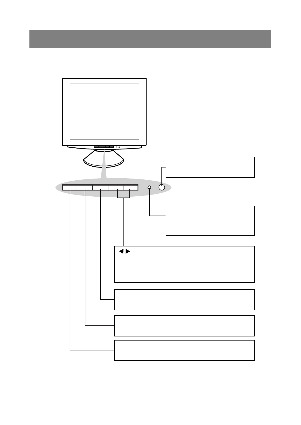
Front view
Control Panel
Product description
Power button (p. 12)
This button switches the monitor ON
and OFF.
Power LED (p. 12)
Green light: In use
Orange light: Power saving mode or
signal failure
Lamp off: Power OFF
buttons
When the On Screen Display (OSD) Menu is displayed:
These buttons are used to increase or decrease the value of a
selected option. (p. 18)
When the OSD Menu is not displayed:
These buttons are used to adjust backlight brightness (p. 17).
SELECT button (p. 18)
This button is used to select menu options when the OSD Menu is
displayed.
MENU button (p. 18)
This button is used to pop-up, select and close the OSD Menu.
INPUT button (p. 12)
Use this button to switch between input signal terminals.
(INPUT 1
↔
INPUT 2)
8
Page 9
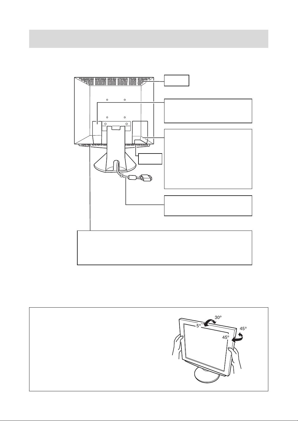
Front view
Product description
Ventilation
openings
Power terminal (p. 10)
Remove the cover to see the power
terminal. The AC adapter is connected
here.
INPUT 2 terminal and USB port
Remove the cover to view the computer
input terminal (INPUT 2) and USB port.
INPUT 2 terminal (p. 11)
Ventilation
openings
Security lock anchor
By connecting a security lock (purchased separately) to the security lock anchor, the
monitor is fixed so that it cannot be transported.
A second computer can be connected
here.
USB port: Downstream (Port 2) (p. 11)
A USB device can be connected here.
USB port: Upstream (Port 1) (p. 11)
A USB-ready computer or self-powered
USB hub can be connected here.
RGB signal cable: INPUT 1 (p. 11)
This is to be connected to the computer's
(i.e. PC etc) analog RGB output terminal.
Note: Never block the ventilation
openings as this may lead to
overheating inside the monitor
and result in malfunction.
The theft prevention hole works in conjunction with Kensington Micro Saver Security
Systems.
Adjusting the angle of the monitor
Lightly holding both sides of the monitor, adjust
it to a suitable viewing angle.
9
Page 10
Connecting the monitor and turning
the monitor on and off
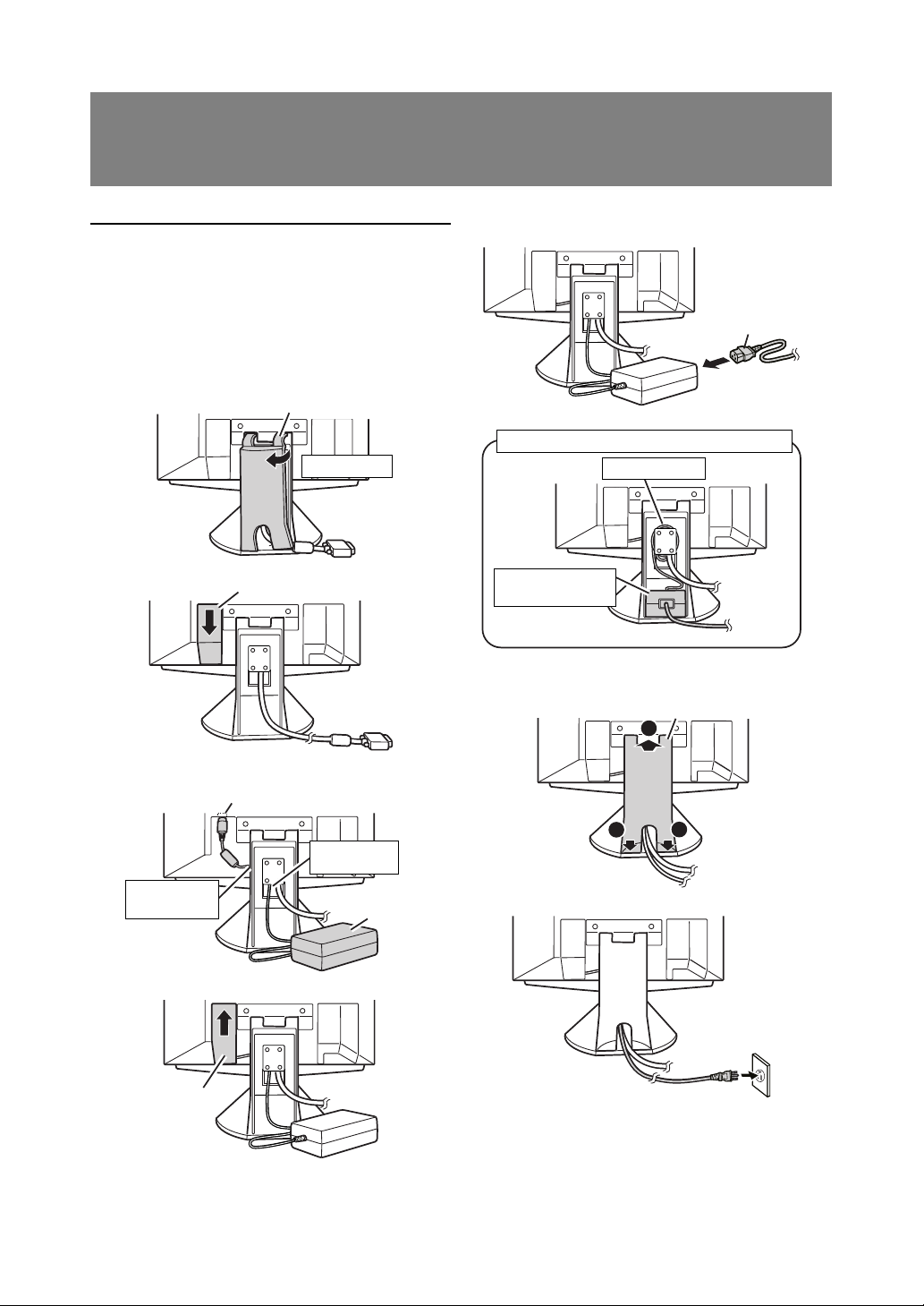
Connecting the monitor to a power source
Use only the AC adapter supplied.
Note:
- Do not overly bend the cable or add extension
cords as this could lead to malfunction.
1. Remove the stand cover.
(Rear View)
2. Remove the cover.
Stand cover
Lift one side
Cover
5. Connect power cord to AC adapter.
Power cord
Fitting the AC adapter inside the stand
Wind the cord
Place adapter
inside stand cavity.
6. Replace stand cover.
Stand cover
2
3. Connect the AC adapter to the monitor's power
terminal.
Power terminal
Run cord
through hole.
Place cord
on hook
AC adapter
4. Replace cover.
Cover
1
7. Place power plug into AC outlet.
10
1
Page 11

Connecting the monitor and turning the monitor on and off
Connecting the monitor to a computer
(PC etc.)
When connecting, ensure that both the monitor and
computer are switched off.
Note:
- Do not overly bend the cable or add extension
cords as this could lead to malfunction.
Firmly insert the analog RGB output
terminal (mini D-sub 15 pin with 3 rows)
then tighten the screws each side.
RGB cable
If connecting to a D-sub 15 pin 2 row Apple
Power Macintosh, attach a Macintosh conversion adapter (to be purchased separately) to
the RGB signal cable.
Macintosh conversion adapter
Connecting to a second computer
A RGB signal cable (to be purchased separately) is
needed to connect a second computer.
Note:
- Do not overly bend the cable or add extension
cords as this could lead to malfunction.
1. Remove the cover
(Rear View)
2. Connect the RGB signal cable (purchased
separately) to the INPUT 2 terminal.
Cover
INPUT 2 terminal
RGB signal cable
(purchased separately)
To the computer's
RGB output terminal
RGB signal cable
After connecting the adapter, tighten the
screws on each side to fix into place.
Note:
- If connecting to the Sun Ultra series, a
conversion adapter (purchased separately) may
be required.
3. Replace the cover.
Connecting a USB device
This monitor can be used with hubs which use the
USB standard (Rev. 1.1).
Downstream (2 ports)
USB devices such as keyboard and mouse can be
connected here. Up to 100mA of power is able to be
supplied per port. Devices requiring more than
100mA cannot be connected.
Upstream (1 port)
USB compatible computers and self-powered hubs
can be connected. (Bus-powered hubs cannot be
connected.)
11
Page 12

Connecting the monitor and turning the monitor on and off
Notes:
- Before connecting, ensure that the shape of the
USB cable connector is correct.
- For information regarding the USB function (such
as set-up) please refer to the operation manual of
the computer to be connected.
- Some computers, OS and other devices may not
be able to be activated. To ascertain a certain
device's USB compatibility, please contact the
manufacturer of the device.
1. Remove the cover.
(Rear View)
Cover
2. Plug one end of the USB cable (provided) into the
monitor's USB upstream port.
Turning the power on
1. Turn on the computer.
2. Press the monitor's power button. The power
LED will be lit green, and the screen will display
an image.
Press power button
Power LED
Green light: In use
Orange light: Power saving mode or signal
failure
Lamp off: Power OFF
Notes:
- Depending on the computer or OS, it may be
necessary to use the computer to install monitor
set-up information. If so, follow the steps below to
install the monitor set-up information. (p. 13)
- When setting up the monitor or a connected
computer for the first time, connecting an
additional computer or after having changed an
aspect of the current system, perform an
automatic screen adjustment before use (p. 17).
USB port: Upstream
(1 port)
3. Connect the other end of the USB cable into the
computer or the USB downstream port.
4. Plug the USB device into the monitor’s USB
downstream port.
USB port: Downstream
(2 ports)
5. Replace the cover.
Changing between input terminals
(INPUT 1
↔↔
↔ 2)
↔↔
When connected to two computers, use the INPUT
button to switch between input signal terminals (i.e.
to choose which computer's screen you want displayed.)
INPUT button
Pushing this button switches between input
signal terminals, so that the screen changes
to display any of the machines connected.
12
Page 13

Connecting the monitor and turning the monitor on and off
Installing set-up information and the ICC profile
(for Windows)
Depending on the computer or OS, it may be necessary to use the computer to operate the installation
of monitor set-up information etc. If so, follow the
steps below to install the monitor set-up information.
(Depending on the computer type, command names
and methods may differ. Please follow the computer’s own operation manual while reading this.)
Note:
This explanation assumes that the floppy disk drive
is "A drive". If the floppy disk drive of your computer
is not "A drive", please read the below substituting
the floppy disk drive you are using in place of "A
drive" or "A".
About ICC profiles
An ICC (International Color Consortium) profile
is a file that describes the color characteristics of
the LCD monitor. By using an application that
works together with an ICC profile, a high color
resolution can be realized.
Notes:
- Windows 98/2000/Me use the ICC profile.
- When the storing Windows 98/2000/Me set-
up information, the ICC profile is also
installed. If you would like to install the ICC
profile only, please refer to Installing the ICC
profile on the following page.
- When using the ICC profile, please set the
[WHITE BALANCE] to [STD] and set the
[COLOR MODE] to [OFF].
[ For Windows 95 ]
Installing monitor set-up information into Windows 95.
This explanation assumes that the floppy disk drive
is "A drive".
1. Place the Utility Disk (provided) into the
computer's A drive.
2. Click on the [Start] button. From [Settings],
choose [Control Panel].
3. Double click on [Display].
4. Click on [Settings], [Advanced Properties], and
[Monitor], then [Change].
5. Click on [Have Disk], confirm that [Copy
manufacturer's files from:] is [A:] then click [OK].
6. Confirm that the monitor details are selected, and
click [OK].
7. Check that the monitor details are displayed, then
click [Apply].
8. Click [OK], and close the window.
9. Remove the Utility Disk from the A drive.
[ For Windows98 ]
Installing monitor set-up information into Windows
98, and setting the monitor's ICC profile as a predetermined value.
This explanation assumes that the floppy disk drive
is "A drive".
If the "Add New Hardware Wizard" has appeared:
1. Place the Utility Disk (provided) into the
computer's A drive.
2. Click [Next].
3. Check [Display a list of all the drivers in a specific
location, so you can select the driver you want.],
then click [Next].
4. When [Models] is displayed, click on [Have Disk],
confirm that [Copy manufacturer's files from:] is
[A:], and click [OK].
5. Confirm that the monitor details are selected,
then click [Next], [Next], and [Finish]. If the "Add
New Hardware Wizard" appears, repeat the
installation commands beginning from 2 above.
6. Remove the Utility Disk from the A drive.
If the "Add New Hardware Wizard" has not appeared:
1. Place the Utility Disk (provided) into the
computer's A drive.
2. Click on the [Start] button. From [Settings],
choose [Control Panel].
3. Double click on [Display].
4. Click on [Settings], [Advanced] and [Monitor].
5. In [Options], check [Automatically detect Plug &
Play monitors] and click on [Change].
6. Click [Next].
7. Click on [Display a list of all the drivers in a
specific location, so you can select the driver you
want.], then click [Next].
8. When [Models] is displayed, click on [Have Disk],
confirm that [Copy manufacturer's files from:] is
[A:], and click [OK].
9. Confirm that the monitor details are selected,
then click [Next], [Next], and [Finish].
10.Check that the monitor details are displayed, then
click [Apply].
11.Click [OK], and close the window.
12.Remove the Utility Disk from the A drive.
[ For Windows2000 ]
Installing monitor set-up information into Windows
2000, and setting the monitor's ICC profile as a
predetermined value.
This explanation assumes that the floppy disk drive
is "A drive".
13
Page 14

Connecting the monitor and turning the monitor on and off
1. Place the Utility Disk (provided) into the
computer's A drive.
2. Click on the [Start] button. From [Settings],
choose [Control Panel].
3. Double click on [Display].
4. Click on [Settings], [Advanced] and [Monitor].
5. Click on [Properties], [Driver] and [Update
Driver].
6. When [Upgrade Device Driver Wizard] appears,
click [Next].
7. Check [Display a list of the known drivers for this
device so that I can choose a specific driver] and
click [Next].
8. When [Models] is displayed, click on [Have disk],
confirm that [Copy manufacturer's files from:] is
[A:], and click [OK].
9. Select the monitor from the list displayed and
click [Next].
10.Click [Next], confirm that the monitor's name
appears on the screen, and click [Finish]. If
[Digital Signature Not Found] appears, click [Yes].
11.Click on [Close].
12.Click [OK], and close the window.
13.Remove the Utility Disk from the A drive.
[ For WindowsMe ]
Installing monitor set-up information into Windows
Me, and setting the monitor's ICC profile as a
predetermined value.
This explanation assumes that the floppy disk drive
is "A drive".
If the "Add New Hardware Wizard" has appeared:
1. Place the Utility Disk (provided) into the
computer's A drive.
2. Check [Specify the location of the driver
[Advanced]] and click [Next].
3. Check [Display a list of all the drivers in a specific
location, so you can select the driver you want.],
then click [Next].
4. When [Models] is displayed, click on [Have Disk],
confirm that [Copy manufacturer's files from:] is
[A:], and click [OK].
5. Select the monitor details from the list, then click
[Next], [Next], and [Finish]. If the "Add New
Hardware Wizard" appears, repeat the
installation commands beginning from 2 above.
6. Remove the Utility Disk from the A drive.
If the "Add New Hardware Wizard" has not appeared:
1. Place the Utility Disk (provided) into the
computer's A drive.
2. Click on the [Start] button. From [Settings],
choose [Control Panel].
3. Double click on [Display].
4. Click on [Settings], [Advanced] and [Monitor].
5. In [Options], check [Automatically detect Plug &
Play monitors] and click on [Change].
6. Check [Specify the location of the driver
[Advanced]] and click [Next].
7. Check [Display a list of all the drivers in a specific
location, so you can select the driver you want.]
and click [Next].
8. When [Models] is displayed, click on [Have Disk],
confirm that [Copy manufacturer's files from:] is
[A:], and click [OK].
9. Select the monitor details, then click [Next],
[Next], and [Finish].
10.Check that the monitor details are displayed, then
click [Apply].
11.Click [OK], and close the window.
12.Remove the Utility Disk from the A drive.
[ Installing the ICC profile ]
Installing the monitor’s ICC profile. (If the set-up
information has already been installed, so too has
the profile, and there is no need to install it.)
This explanation assumes that the floppy disk drive
is "A drive".
1. Place the Utility Disk (provided) into the
computer's A drive.
2. Click on the [Start] button. From [Settings],
choose [Control Panel].
3. Double click on [Display].
4. Click on [Settings] and [Advanced].
5. Click on [General] and from [Compatibility] select
[Apply the new display settings without
restarting], then click on [Color Management].
6. Click [Add], and select [3 ½ Floppy [A:]] as the
file location.
7. Choose the color profile that you would like to
install, and click on [Add].
8. Choose the profile and click on [Set As Default].
9. Click [OK], and close the window.
10.Remove the Utility Disk from the A drive.
When using the ICC profile, please set the [WHITE
BALANCE] to [STD] and set the [COLOR MODE] to
[OFF].
14
Page 15

Connecting the monitor and turning the monitor on and off
Installing ColorSync profile (for MacOs)
About ColorSync profiles
ColorSync is the color management system of
Apple Computer, Inc.ColorSync is the function to
realize color reappearance with the application
which coped with it.A ColorSync profile is a file
that describes the color characteristics of the
LCD monitor.
Notes:
- The ColorSync profile of this opportunity
copes with it after MacOS8.5.
- When using the ColorSync profile, please set
the [WHITE BALANCE] to [STD] and set the
[COLOR MODE] to [OFF].
Setting ColorSync profile
- A floppy disk drive is necessary.And, "PC
Exchange" or "File Exchange" must be installed
in the system.
- Depending on the computer or OS, command
names and methods may differ. Please follow the
computer's own operation manual while reading
this.
1. Place the Utility Disk (provided) into the
computer's floppy disk drive.
2. The profile used is copied onto the ColorSync
profile folder in the system folder.
3. The profile used is chosen with ColorSync of the
control panel.
Turning the power off
1. Turn the computer off.
2. Press the monitor's power button.
The Power LED will disappear.
CAUTION!
Do not leave the monitor in contact with rubber or
plastic items for long periods of time as this could
lead to color change or change in shape.
15
Page 16

Adjusting the screen display
If necessary, the screen can be adjusted as follows.
Automatic screen adjustment (p. 17)
The CLOCK, PHASE, H-POS (horizontal positioning) and V-POS (vertical positioning) functions can
be adjusted automatically.
Adjustment of backlight (p. 17)
Brightness of backlight can be adjusted.
Manual adjustment (p. 18)
Fine adjustments can be made using the On Screen
Display (OSD) Menu.
Note:
- All adjustments will be saved even after turning
the power off.
Useful functions and tips
Resetting MENU 1 (ADJUSTMENT)
MENU 1 (ADJUSTMENT) values can be returned to
their original ex-factory values in one command.
1. Turn on the monitor power.
2. Press the MENU button and the
simultaneously. When [RESET] appears on the
screen, the reset is complete.
Resetting all adjustment values
All adjustment values can be returned to their
original ex-factory values in one command.
1. Turn off the monitor power.
2. Press the MENU button and the SELECT button
simultaneously, and while doing this press the
power button (i.e. turn the power on). When [ALL
RESET] appears on the screen, the reset is
complete.
Note:
- While ALL RESET is displayed, the control
buttons are disabled.
- It is not possible to reset values when the
adjustment lock is in place. Remove the
adjustment lock before attempting to operate
control buttons.
button
Adjustment lock function
By disabling the control buttons (i.e. setting the lock)
any attempted changes to adjusted values will be
voided.
1. Turn off the monitor power.
2. While pressing the MENU button, press the
power button (i.e. turn the power on).
When the menu is unlocked:
[ADJUSTMENT LOCKED] will appear on the
screen, and the lock will be set.
When the menu is locked:
[ADJUSTMENT UNLOCKED] will appear on the
screen, and the lock will be removed.
Note:
- When the lock is in place, all buttons other than
the power button are disabled.
Choosing a message language
Messages displayed on the screen and OSD Menu
contents can be changed to the following languages.
Dutch, English, French, German, Spanish, Italian,
Swedish.
1. Turn off the monitor.
2. Pressing the
press the power button (i.e. turn the power on).
The Language Selection Menu (LANGUAGE) will
be displayed on the screen.
3. Use the SELECT button to choose a language.
4. Press the MENU button.
The setting is complete. From now, messages
and adjustment menus will be displayed in the
chosen language.
and buttons simultaneously,
16
Page 17

Adjusting the screen display
Automatic screen adjustment
Options in MENU 1 (ADJUSTMENT) can be adjusted automatically (CLOCK, PHASE, H-POS, VPOS).
Note:
- When setting up the monitor or a connected
computer for the first time, connecting an
additional computer or after having changed an
aspect of the current system, perform an
automatic screen adjustment before use
Automatic adjustment screen display
To perform an automatic adjustment, first display an
image that makes the entire screen very bright. If
you are using Windows, you can also use the
Adjustment Pattern on the accompanying Utility Disk
for Windows.
Displaying the Adjustment Pattern (for Windows)
This explanation is for Windows 95/98/2000/Me, and
assumes that the floppy disk drive is [A drive].
Note:
- If the floppy disk drive of your computer is not
"A drive", please read the below substituting the
floppy disk drive you are using in place of
"A drive" or "A".
1. Place the Utility Disk (provided) into the
computer's A drive.
2. Open [My Computer] and select [3 ½ Floppy
(A:)]. If using Windows 3.1, open [File Manager]
and choose "A drive".
3. Double click on [Adj_uty.exe] to run the
Adjustment Program. The Adjustment Pattern will
appear.
Adjustment pattern
Adjusting the screen automatically
1. Press the MENU button.
The ADJUSTMENT Menu will be displayed.
2. Press the button.
The screen will become dark and [ADJUSTING]
will be displayed. After a few seconds the
ADJUSTMENT Menu will return. (The automatic
adjustment is now complete.)
3. Press the MENU button 4 times to make the On
Screen Display (OSD) Menu disappear.
Notes:
- In most cases the monitor is ready to be used
after automatic adjustment.
- If necessary due to any of the following, manual
adjustments (p. 18) can be made after the
automatic adjustment.
- When further fine adjustment is needed.
- When the computer's video input signals are
Composite Sync or Sync On Green.
(Automatic adjustments may not be possible.)
- When [OUT OF ADJUST] is displayed.
(When the screen displays an entirely dark
image, the automatic screen adjustment may
be disabled. When making an automatic
adjustment, be sure to either use the
Adjustment Pattern or try displaying an image
that makes the entire screen very bright.)
Adjusting the backlight
Notes:
- After completing the adjustment, press the
computer's [Esc] key to exit the Adjustment
Program.
- If your computer's display mode is set to 65K
colors, you may see the different color levels in
each color pattern or the gray scale may look
colored. (This is due to the input signal
specification and is not a malfunction.)
The backlight brightness can be adjusted.
Carry out the commands without the On Screen
Display (OSD) Menu displayed. If the OSD Menu is
displayed, press the MENU button (several times
may be required) and begin when the OSD Menu
has disappeared.
1. Without the OSD Menu being displayed, push the
or the button. At the bottom of the screen the
BRIGHT bar will appear.
2. Adjust by pressing the button (darker) or
button (lighter).
The BRIGHT bar automatically disappears several
seconds after the last command.
17
Page 18

Adjusting the screen display
Manual screen adjustment
Fine adjustments can be made using the On Screen
Display (OSD) Menu provided.
The screen display during adjustment
If using Windows, the Adjustment Pattern on the
accompanying Utility Disk for Windows can be used.
(p. 17)
If using a computer other than Windows, the adjustment pattern cannot be used. Display an image that
makes the entire screen very bright, and adjust
while watching the screen.
Note:
- This explanation is based on using the Adjust-
ment Pattern (for Windows) to make adjustments.
Adjusting
1. Press the MENU button. The ADJUSTMENT
Menu will be displayed.
MENU 1: ADJUSTMENT
MANUAL: Individual menu options are manually
adjusted.
AUTO: Every menu option is automatically
adjusted
Notes:
- Press the
- To choose a menu option: SELECT button
- To go to MENU 2: MENU button
CLOCK
The figure below demonstrates how to adjust so that
vertical flicker noise is not emitted. (
button to select AUTO.
buttons)
Vertical flicker noise
At this point relevant menu options can be adjusted.
Each time the MENU button is pressed, the next
menu is selected. (MENU 1 → 2 → 3 → 4 → OSD
Menu disappears)
Note:
- The OSD Menu automatically disappears ap-
proximately 20 seconds after the last command.
PHASE
The figure below demonstrates how to adjust so that
horizontal flicker noise is not emitted. (
Note:
- Adjustments to PHASE should be made only
after CLOCK has been correctly set.
Horizontal flicker noise
H-POS (horizontal positioning) and V-POS
(vertical positioning)
To center the screen image within the boundaries of
the screen, adjust the left-right (H-POS) values and
the up-down (V-POS) values. (
buttons)
buttons)
Screen frame
18
Page 19

Adjusting the screen display
MENU 2: GAIN CONTROL
BRIGHT (brightness) and CONT (contrast) are
optimized before shipment, but depending on the
type of computer being used, further adjustment
may be necessary.
MANUAL: Individual menu options are manually
adjusted.
AUTO: Every menu option is automatically
adjusted using the Auto Gain Control*
function,
Notes:
- Press the
- To choose a menu option: SELECT button
- To go to MENU 3: MENU button
*Auto Gain Control function
The Auto Gain Control adjusts contrast and
brightness based on the brightest color of the
image displayed. If you are not using the
Adjustment Pattern it is necessary to have an
area of at least 5 mm x 5 mm of white image
displayed, and if not adjustments may not be
possible. (In such case, [OUT OF ADJUST] will
appear and setting values remain unchanged.)
BRIGHT (brightness)
Total screen brightness can be adjusted while
watching the color pattern. (
button to select AUTO.
buttons)
MENU 3: WHITE BALANCE
WHITE BALANCE can be adjusted as necessary.
(As adjustments are made before shipment, there is
no real necessity for further alteration.)
Notes:
- On settings other than [STD] not all graduations
can be displayed. To display all graduations, set
to STD.
- Selecting USER will display the setting values for
R-CONT, G-CONT and B-CONT, enabling fine
adjustments.
- To choose a menu option: SELECT button
- To go to MENU 4: MENU button
COOL . . . Color tone bluer than standard
- . . . . . . Color tone slightly bluer than standard
STD . . . . . Color tone standard setting
- . . . . . . Color tone slightly redder than standard
WARM . . . Color tone redder than standard
USER
R-CONT . . . . . . .
G-CONT . . . . . . .
B-CONT . . . . . . .
button for blue-green
button for red
button for purple
button for green
button for yellow
button for blue
Color pattern
CONT (Contrast)
While watching the color pattern, adjustments can be
made so that all graduations appear. (
buttons)
19
Page 20

Adjusting the screen display
MENU 4: MODE SELECT
The resolution can be adjusted
Notes:
- To choose a menu option: SELECT button
- When adjustment complete: MENU button
OSD H-POSITION (OSD horizontal position)
The position of the OSD display can be moved to
the left and right. (
OSD V-POSITION (OSD vertical position)
The position of the OSD display can be moved up
and down. (
INPUT (Input mode)
The input mode can be set (
VESA: VESA mode
MAC: Power Macintosh mode
400 LINES (degree of resolution)
You can specify the horizontal resolution of a 400-line
screen when using US text, etc. (
640 640 X 400 dot mode
720 720 X 400 dot mode (US text etc.)
buttons)
buttons)
buttons)
buttons)
LEVEL (Level of scaling)
When EXPAND is ON1 or ON2, the sharpness of
the image can be adjusted. (
Note:
- When EXPAND is OFF, no adjustments can be
made.
COLOR MODE
OFF It is indicated in the color of the LCD
monitor origin.
ON It is corrected in the more suitable color,
and indicated in the computer image.
Note:
- Set up WHITE BALANCE in STD when you turn
on COLOR MODE.
buttons)
Note:
- As the resolution input for other than 400 lines is
done automatically, there is no need to set it.
EXPAND (Screen expansion)
For display modes of less than 1600 X 1200 pixels,
the display can be expanded if desired.
buttons)
(
OFF It doesn't expand.
ON1 It expands by the aspect ratio fixation.
ON2 It spreads throughout the whole of the
screen.
Notes:
- Display modes of 1600 X 1200 pixels cannot be
changed.
- If a resolution of 1600 X 1200 pixels cannot be
achieved even after expansion is attempted, the
screen's perimeter will display black. (This is not
a malfunction.)
20
Page 21

Monitor care and repair
Monitor care
Always remove the plug from the AC outlet when
cleaning the monitor.
Cabinet and control panel section
Use a soft dry cloth to lightly wipe away any grime
from the cabinet and control panel.
If they are very dirty, apply neutral detergent to a
dampened soft cloth, wring it out well and wipe away
grime.
LCD panel section
Use a soft dry cloth to lightly wipe away dirt and dust
from the surface of the LCD panel. (A soft cloth such
as gauze or that used for lens cleaning is suitable.)
CAUTION!
- Never use thinner, benzine, alcohol, glass
cleaner, etc, as this could lead to color change or
change in shape.
- Never scratch the monitor with anything hard or
apply strong pressure as this could leave marks
or result in malfunction.
Storage
If the monitor will not be used for a long period of
time, be sure to remove the power plug from the AC
outlet.
CAUTION!
Do not leave the monitor in contact with rubber or
plastic items for long periods of time as this could
lead to color change or change in shape.
Troubleshooting
If you think the monitor may be faulty, please check
the following points before taking it to be repaired.
If afterwards it still does not work, please contact the
shop where you purchased the monitor or your
nearest Sharp authorized Service Center.
The monitor's florescent tubes have a limited life
span.
- If the screen darkens, persistently flickers or
does not light up, it may be necessary to
replace the florescent tube unit. Please
inquire at the shop where you purchased the
monitor or your nearest Sharp authorized
Service Center. (Never attempt this
replacement on your own.)
- In the initial period of use, due to the
characteristics of florescent tubes the screen
may flicker. (This is not a malfunction.)
Should this happen, check by first turning off
the power, then turning it on again.
No image appears on the monitor (Power LED is not
lit)
- Are the AC adapter and power cord connected
properly? (p. 10)
No image appears on the monitor (Power LED is lit)
- Try pressing the INPUT button to switch between
incoming power terminals. (p. 12)
- Is the computer connected properly? (p. 11)
- Is the computer turned on?
- Does the computer's signal timing correspond to
monitor specifications? (p. 23)
- Is the computer in power-saving mode?
Control buttons do not work
- Is the adjustment lock on? (p. 16)
Only VGA image is displayed
- Does the Windows display timing setting meet
monitor specifications? Refer to the monitor
signal timings (p. 23) and set to appropriate
timing.
The image appears distorted
- Does the computer's signal timing correspond to
monitor specifications? (p. 23)
- Perform automatic adjustment. (p. 17)
21
Page 22

Specifications
Product specifications Dimensions (Units: mm)
LCD display
19.6 inches (50 cm measured diagonally)
Super High resolution and Anti Glare Low
Reflection TFT LCD module
Resolution (max.)
UXGA 1600 x 1200 pixels
Displayable colors (max.)
16.77 million colors (8 bit)
Brightness (max.)
200cd/m
2
Dot pitch
0.249(H) 0.249(V) mm
Contrast ratio
300:1
Angle of visibility
Left-right 150°; Up-down 150°
Screen display size
Horizontal 398.4 mm x Vertical 298.8 mm
Video signal
Analog RGB (0.7Vp-p) [75Ω]
Sync signal
Separate Sync (TTL level: +/-), Sync on
Green, Composite Sync (TTL level: +/-)
Expansion compensation
Digital screening (enlargement of display to
correct VGA/SVGA/XGA/SXGA)
Plug & Play
VESA: DDC1/DDC2B compatible
Power management
VESA: based on DPMS
Computer signal input terminal
2 x 15 pin mini D-sub (3 rows)
USB hub function
1 upstream port, 2 downstream ports (buspowered hub based on USB standard Rev 1.1)
Screen tilt
Upward 0° -30°; downward 0° - 5°
Screen swivel
90° from left through right
Power supply
AC100-240V (Use special AC adapter)
Temperature of operating environment
5 - 35°C
Power consumption
48W max. (3.5W when in power-saving mode)
Dimensions (W x D x H, excluding rubber base)
483 mm x 218 mm x 478 mm
Weight
Approx. 10.5 kg (excluding AC adapter)
397
478
218
483
227
73
22
Page 23

Specifications
Signal timings The connector pin
Display mode
VESA
US TEXT
Power
Macintosh
series
Sun Ultra
series
640x480
640x400
720x400
800x600
1024x768
1152
x864
1280
x960
1280x1024
x
1200
1600
720x400
640x480
832x624
1024
x768
1152
x870
1280x1024
x
1200
1600
x768
1024
1152
x900
1280x1024
1600
x
1000
Hsync
31.5kHz
37.9kHz
37.5kHz
43.3kHz
37.9kHz
37.9kHz
35.1kHz
37.9kHz
48.1kHz
46.9kHz
53.7kHz
48.4kHz
56.5kHz
60.0kHz
68.7kHz
67.5kHz
60.0kHz
85.9kHz
64.0kHz
80.0kHz
91.1kHz
75.0kHz
31.5kHz
35.0kHz
49.7kHz
60.2kHz
68.7kHz
64.0kHz
80.0kHz
91.1kHz
75.0kHz
48.3kHz
53.6kHz
56.6kHz
61.8kHz
71.8kHz
71.7kHz
81.1kHz
68.6kHz
Vsync
60.0Hz
72.0Hz
75.0Hz
85.0Hz
85.0Hz
85.0Hz
56.0Hz
60.0Hz
72.0Hz
75.0Hz
85.0Hz
60.0Hz
70.0Hz
75.0Hz
85.0Hz
75.0Hz
60.0Hz
85.0Hz
60.0Hz
75.0Hz
85.0Hz
60.0Hz
70.0Hz
66.7Hz
74.6Hz
75.0Hz
75.0Hz
60.0Hz
75.0Hz
85.0Hz
60.0Hz
60.0Hz
66.0Hz
70.0Hz
66.0Hz
76.1Hz
67.2Hz
76.0Hz
66.0Hz
Dot frequency
25.175MHz
31.5MHz
31.5MHz
36.0MHz
31.5MHz
35.5MHz
36.0MHz
40.0MHz
50.0MHz
49.5MHz
56.25MHz
65.0MHz
75.0MHz
78.75MHz
94.5MHz
108.0MHz
108.0MHz
148.5MHz
108.0MHz
135.0MHz
157.5MHz
162.0MHz
28.3MHz
30.2MHz
57.3MHz
80.0MHz
100.0MHz
108.0MHz
135.0MHz
157.5MHz
162.0MHz
64.13MHz
70.4MHz
74.25MHz
108.01MHz
117.01MHz
117.01MHz
134.99MHz
135.76MHz
Input connector diagram (Mini D-sub connector with 15 pins)
Number Function
1 Red video signal input
2 Green video signal input
3 Blue video signal input
4 GND
5 GND
6 For red video signal GND
7 For green video signal GND
8 For blue video signal GND
9 N.C.
10 GND
11 GND
12 DDC data
13 For Hsync signal input
14 For Vsync signal input
15 DDC clock
Notes:
- All are compliant only with non-interlace.
- Frequencies for Power Macintosh and the Sun
Ultra series are reference values.
- If the monitor is receiving timing signals that are
not compatible, [OUT OF TIMING] will appear.
Follow your computer’s instruction manual to set
the timing to be compatible with the monitor.
- If the monitor is not receiving any signal (synch
signal), [NO SIGNAL] will appear.
23
Page 24

Specifications
Standards and compatibility
Power management
The monitor is based on VESA DPMS (Display
Power Management Signaling).
To activate the monitor's Power Management function, both the video card and the computer must
conform to the VESA DPMS standard.
DPMS mode Screen Power H-sync V-sync
ON Display on 48W Yes Yes
STANDBY No Yes
SUSPEND Display off
OFF No No
consumption
Less than
3.5W
Ye s N o
DDC (Plug & Play)
This monitor supports the VESA DDC (Display Data
Channel) standard.
DDC is a signal standard for carrying out Plug &
Play functions on the monitor or PC. It transfers
information such as degree of resolution between
the monitor and PC. You can use this function if your
PC is DDC compliant and if it is set so that it can
detect the Plug & Play monitor.
There are many varieties of DDC due to the differences between systems. This monitor works with
DDC1 and DDC2B.
24
Page 25

Instructions for attaching a VESA compliant arm
An arm or stand based on the VESA standard
(purchased separately) can be attached to the
monitor.
Procurement of the arm or stand is at the customer's discretion.
Arms or stands able to be used
Attachments must satisfy the following.
- Compatible with the VESA standard
- Have a gap of at least 100 mm x 100 mm
between the screw holes on the section to be
attached
- Not be likely to fall off or break off after being
attached to the monitor.
How to attach the arm or stand
Note:
- While following these instructions, please also
refer to the installation instructions in the
operation manual included with the arm or stand
- Do not overly bend the cable or add extension
cords as this could lead to malfunction.
1. Spread out a soft cloth on a suitable horizontal
surface.
2. Being careful not to damage the monitor, gently
lay the monitor on it display-side down.
5. Remove the four screws and then remove the
stand from the monitor.
Four screws
Stand
6. Attach the arm to the monitor with the four
screws.
The screws used to attach the arm should be M4
screws with a length of 8 mm ~ 10 mm protruding
from the surface to be attached.
Using any other kind of screw may lead to the
monitor falling off or damage to the internal part of
the monitor
3. Remove the stand cover.
(Rear view)
Stand cover
Lift one side
4. Remove the two screws, and remove the cover.
Cover
Two screws
Screw used to attach arm
Arm
Part of monitor to which arm
is attached
25
Page 26

Memo
26
Page 27

Memo
27
Page 28

SHARP CORPORATION
© 2001 SHARP CORPORATION
 Loading...