

Page 1
q
SERVICE MANUAL
MODEL
CONTENTS
CHAPTER 1. OUTLINE OF THE PRODUCT,
NOMENCLATURE AND FUNCTION. . . . . . . . . . . . . . . . . .1 - 1
CODE : 00Z
LLT17A4SME
LCD MONITOR
LL-T17A4-H
LL-T17A4-B
CHAPTER 2. CONNECTION, ADJUSTMENT,
OPERATION, AND FUNCTIONS. . . . . . . . . . . . . . . . . . . . .2 - 1
CHAPTER 3. DISASSEMBLY AND ASSEMBLY. . . . . . . . . . . . . . . . . . . .3 - 1
CHAPTER 4. BLOCK DIAGRAM . . . . . . . . . . . . . . . . . . . . . . . . . . . . . . . .4 - 1
CHAPTER 5. TROUBLE SHOOTING . . . . . . . . . . . . . . . . . . . . . . . . . . . .5 - 1
CHAPTER 6. CIRCUIT DIAGRAM. . . . . . . . . . . . . . . . . . . . . . . . . . . . . . .6 - 1
CHAPTER 7. PWB LAYOUT . . . . . . . . . . . . . . . . . . . . . . . . . . . . . . . . . . .7 - 1
Model Name
LL-T17A4H LL-T17A4U LL-T17A4E Ivory
LL-T17A4B LL-T17A4Y LL-T17A4P Black
Product Name
For USA For Other
Color
Parts mark ed w ith "!" are important for maintaining the safety of the set. Be sure to replace these parts with specified
ones for maintaining the safety and performance of the set.
This document has been pub lished to be used
SHARP CORPORATION
for after sales service only.
The contents are subject to change without notice.
Page 2
CHAPTER 1. OUTLINE OF THE PRODUCT, NOMENCLATURE AND FUNCTION
1. SPECIFICATIONS
■
■ Product specifications
■ ■
• Model name
LL-T
17A4
-H (Ivory)/LL-T
17A4
-B (Black)
• LCD display
43 cm measured diagonally
TFT LCD module
• Resolution (max.)
SXGA 1280 x 102 4 pixels
• Displayable colors (max.)
Approx. 16.19 million colors (6bit+FRC)
• Brightness (max.)
2
250cd/m
• Dot pitch
0.264 (H) x 0.264 (V) mm
• Contrast ratio
430 : 1
• Angle of visibility
Left-right 170°; Up- down 150° (co ntrast rat io > 5)
• Screen display size
Horizonta l 337.9 mm x Ver t ical 270.3 m m
• Video signal
Analog RGB (0.7Vp- p ) [7 5Ω]
• Sync signal
Separate Sync (TTL level: +/-), Sync on Green, Composite Sync (TTL
level: +/-)
• Expansion compensation
Digital sca li ng ( Enla r ges VGA/ SVGA /XGA etc. to ful l s cr een si ze .)
• Plug & Play
VESA DDC2B compatible
• Power management
VESA: based on DPMS
• Speaker output
1W + 1W
• Input signal terminal
Mini D-sub 15 pin (3 row)
• Audio input terminal
Mini stereo jack
• Headphone terminal
Mini stereo jack
• Screen tilt
Upward approx. 0° - 20° ; down ward appro x. 0° - 5°
• Screen swivel
Approx. 90° from lef t th ro ugh ri g ht (T urn t abl e ty pe)
• Power supply
AC100 - 240V, 50/60Hz
• Temperature of operating environment
5 - 35°C
• Power consumption
33 W (with no audio inp ut)
(36 W maximum, 1.6 W when in power-savin g mode)
• Dimensions
Approx.
381 (W) x 222 (D) x 365 - 412 (H) mm
• Weight
Approx. 6.3kg (approx. 4.1kg excluding stand)
(Excluding signal cable.)
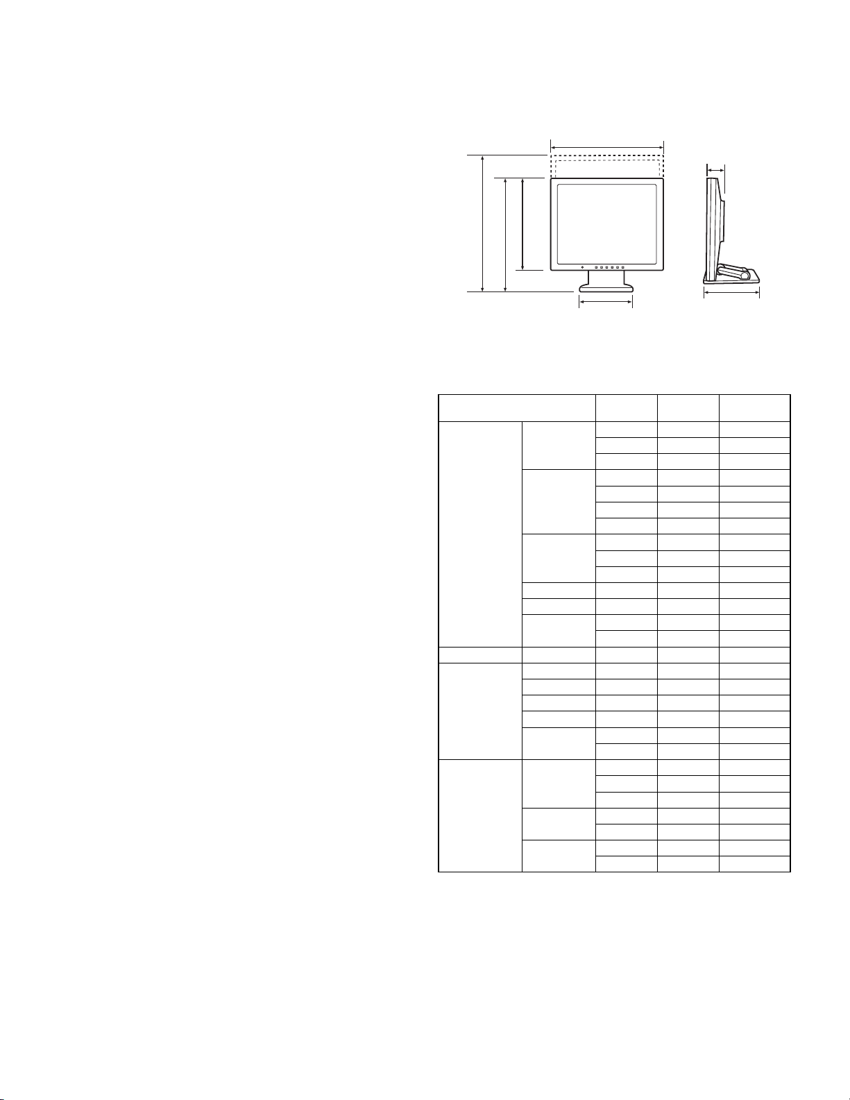
■
■ Dimensions (Units: mm)
■ ■
381
68
412
365
321
222202
• Analog signal cable: approx. 1.8 m
• Audio cable: approx. 1.8 m
■
■ Relevant signal timings
■ ■
Display mode Hsync Vsync
VESA 640 x 480 31.5kHz 60Hz 25.175MHz
37.9kHz 72Hz 31.5MHz
37.5kHz 75Hz 31.5MHz
800 x 600 35.1kHz 56Hz 36.0MHz
37.9kHz 60Hz 40.0MHz
48.1kHz 72Hz 50.0MHz
46.9kHz 75Hz 49.5MHz
1024 x 768 48.4kHz 60Hz 65.0MHz
56.5kHz 70Hz 75.0MHz
60.0kHz 75Hz 78.75MHz
1152 x 864 67.5kHz 75Hz 108.0MHz
1280 x 960 60.0kHz 60Hz 108.0MHz
1280 x 1024 64.0kHz 60Hz 108.0MHz
80.0kHz 75Hz 135.0MHz
US text 720 x 400 31.5kHz 70Hz 28.3MHz
Power
Macintosh
series
Sun
Ultra series
640 x 480 35.0kHz 66.7Hz 30.2MHz
832 x 624 49.7kHz 74.6Hz 57.3MHz
1024 x 768 60.2kHz 75Hz 80.0MHz
1152 x 870 68.7kHz 75Hz 100.0MHz
1280 x 1024 64.0kHz 60Hz 108.0MHz
80.0kHz 75Hz 135.0MHz
1024 x 768 48.3kHz 60Hz 64.13MHz
53.6kHz 66Hz 70.4MHz
56.6kHz 70Hz 74.25MHz
1152 x 900 61.8kHz 66Hz 94.88MHz
71.8kHz 76.2Hz 108.23MHz
1280 x 1024 71.7kHz 67.2Hz 117.01MHz
81.1kHz 76Hz 134.99MHz
Dot
frequency
• Recommended resolution is 1280 x 1024.
• All are compliant only with non-interlaced.
• Frequencies for Power Macintosh and Sun Ultra series are reference
values. To connect, another adapter (commercially available) may be
required.
• If the monitor is receiving timing signals that are not compatible, [OUT
OF TIMING] will appear.
Follow your computer's instruction manual to set the timing so that it
is compatible with the monitor.
• If the monitor is not receiving any signal (synch signal), [NO SIGNAL]
will appear.
LL-T17A4-H/B OUTLINE OF THE PRODUCT, NOMENCLATURE AND FUNCTION
1 – 1
Page 3
■
12 3 4
5
89FGH
■ The analog RGB input connector pin
■ ■
(Mini D-sub connector with 15 pins)
5 1234
10
15 11121314
6789
2. PRODUCT DESCRIPTION
I
No. Function No. Function
1 Red video signal input 9 +5V
2 Green video signal input 10 GND
3 Blue video signal input 11 GND
4 GND 12 DDC data
5 GND 13 For Hsync signal input
6 For red video signal GND 14 For Vsync signal input
7 For green video signal GND 15 DDC clock
8 For blue video signal GND
■
■ Power management
■ ■
The monitor is based on VESA DPMS (Display Power Managemant
Signaling).
To activate the monitor's Power Management function, both the video
card and the computer must conform to the VESA DPMS standard.
DPMS mode Screen
ON Display on 36W Yes Yes
STANDBY
SUSPEND Yes No
OFF No No
■
■ DDC (Plug & Play)
■ ■
This monitor supports the VESA DDC (Display Data Channel) standard.
DDC is a signal standard for carrying out Plug & Play functions on the
monitor or PC. It transfers information such as degree of resolution
between the monitor and PC. You can use this function if your PC is
DDC compliant and if it is set so that it can detect the Plug & Play monitor.
There are many varieties of DDC due to the differences between systems. This monitor works with DDC2B.
Display off 1.6W
Power
consumption
H-sync V-sync
No Yes
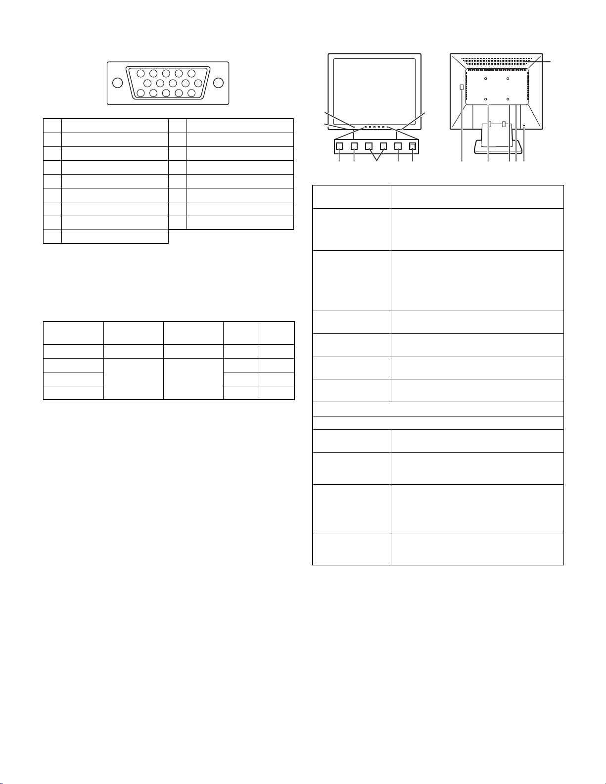
7
6
1 ME NU button This button is us ed t o po p-u p, s ele ct an d cl ose
2 c/MODE button When the OSD Menu is displayed:
3 e d buttons When the OSD Menu is displayed:
4 Power but ton Pressing this button turns the power on.
5 Power LED This LED is lit green when in use and orange
6
Speakers
7 Headphone ter-
minal
8 Main power switch
9 Power t erminal
F Analog RG B
input term i n al
G Audio input termi-
nal
H Security lock
anchor
I Ventilation
openings
the OSD (On Screen Display) Menu.
When the OSD Menu is not displayed:
When the OSD Menu is not displayed:
Press the button again to turn the power on.
when in power-saving mode.
Audio enterin g via the exter nal device co n-
nected to the monitor can be heard.
Headphones (commercially available) can be
connected here.
The analog signal cable is connected here. The
analog signal cable included should be used.
A computer's audio o utput t erm inal can be connected here. The aud io cable inc luded shou ld
be used.
By connecting a security lock (commercially
available) to the se cur i ty lock anchor, the m onitor is fixed so that it cannot be transported.
The security slot works in conjunction with
Kensington Micro Saver Security Systems.
Note: Never blo ck th e ventil ation o pening s as
this may lead to overheating inside the monitor
and result in malfunction.
6
This button is used to select menu options.
This button is used to set DISPLAY MODE.
These buttons are used to select an option or
adjust the value of the selected option.
These buttons are used to adjust backlight
brightness and speaker volume.
LL-T17A4-H/B OUTLINE OF THE PRODUCT, NOMENCLATURE AND FUNCTION
1 – 2
Page 4
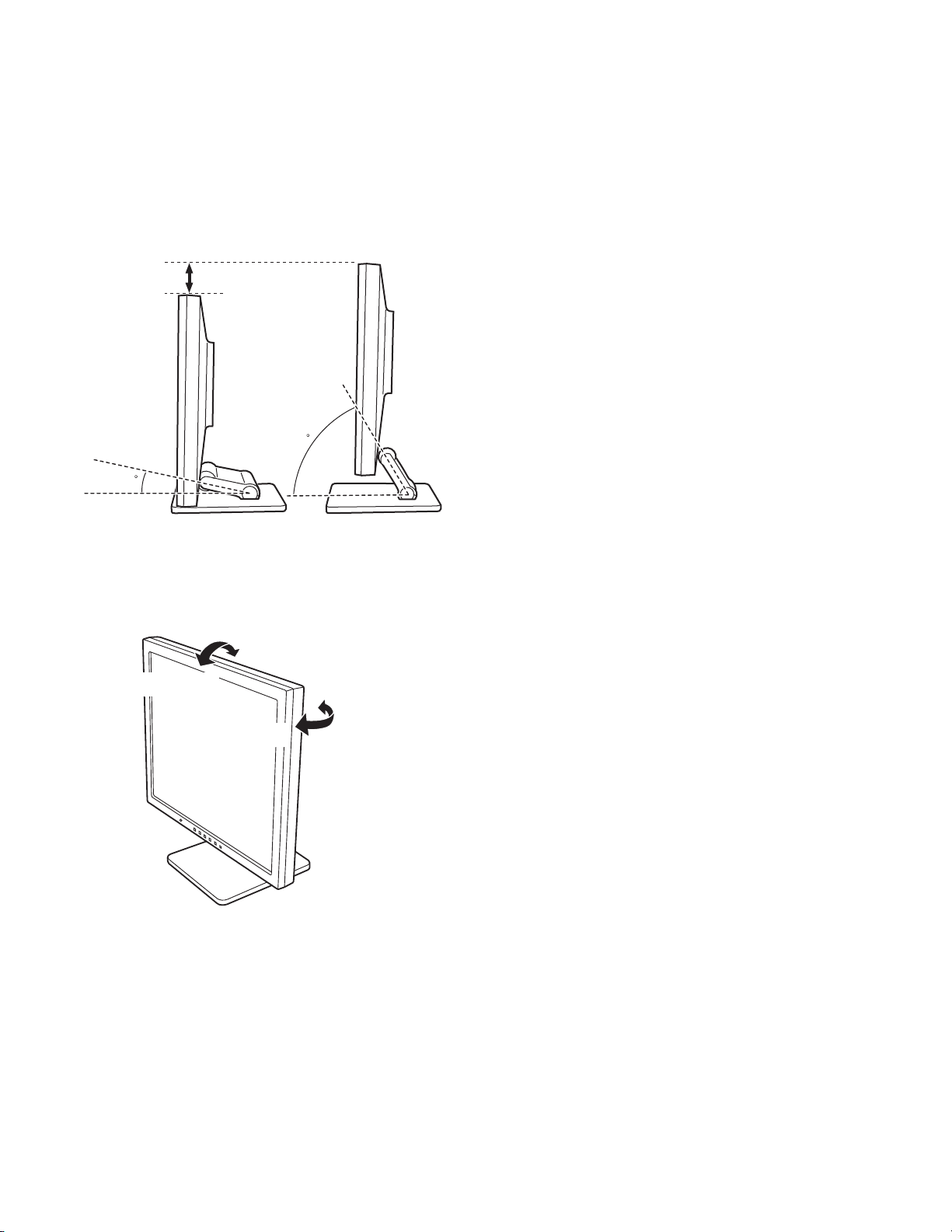
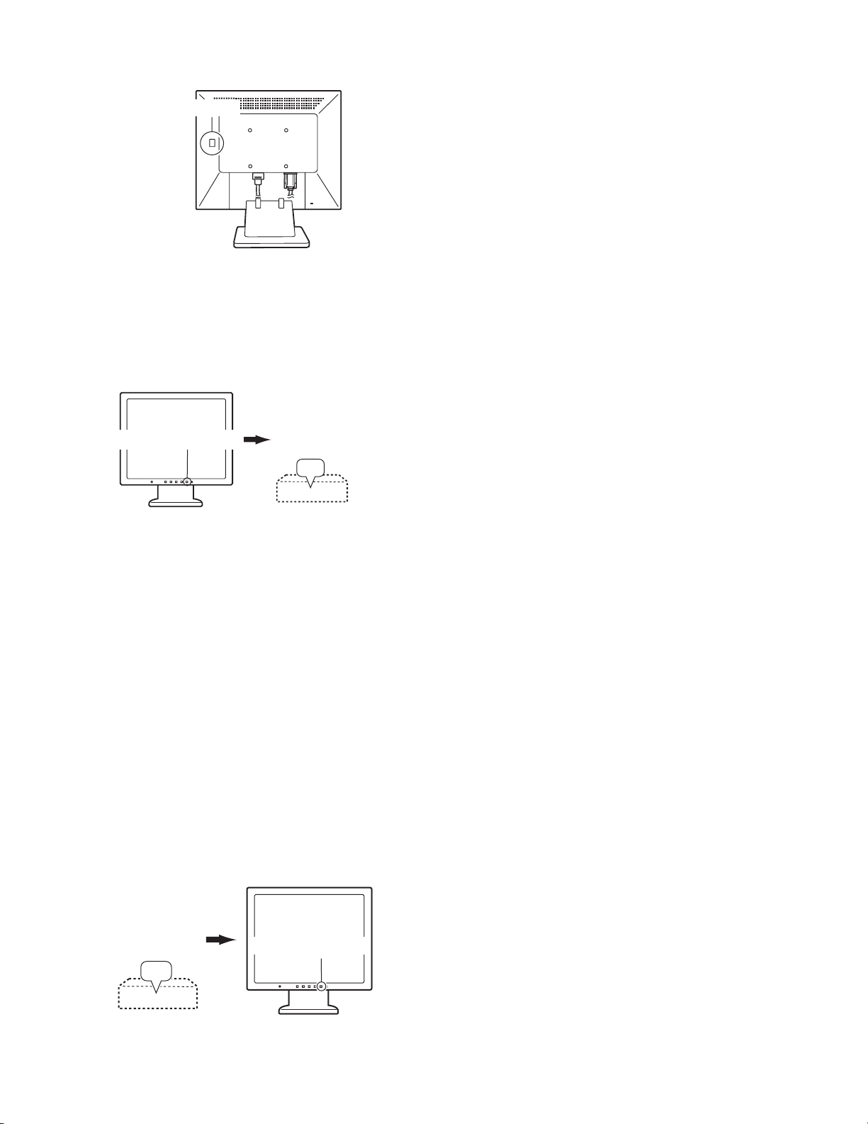
■
■ Height adjustment, angle adjustment
■ ■
Caution:
• Pressure from hands on the LCD panel could cause damage.
• Do not attempt to move the monitor beyond its movement range.
Applying excessive force to move the monitor may damage the
product.
• Be careful not to allow your fingers to be pinched.
Height adjustment
Lowest position Highest position
approx. 47mm
approx. 60
approx. 20
• When positioning the display higher, hold the stand tight so that it
does not move together with the display.
Angle adjustment
approx. 20˚
approx. 5˚
approx. 45˚
approx. 45˚
LL-T17A4-H/B OUTLINE OF THE PRODUCT, NOMENCLATURE AND FUNCTION
1 – 3
Page 5
CHAPTER 2. CONNECTION, ADJUSTMENT, OPERATION, AND FUNCTIONS
1. CONNECTION
Caution:
• When connecting, ensure that both the monitor and computer are switched off.
• Be careful not to overly bend the cable or add extension cords as this could lead to a malfunction.
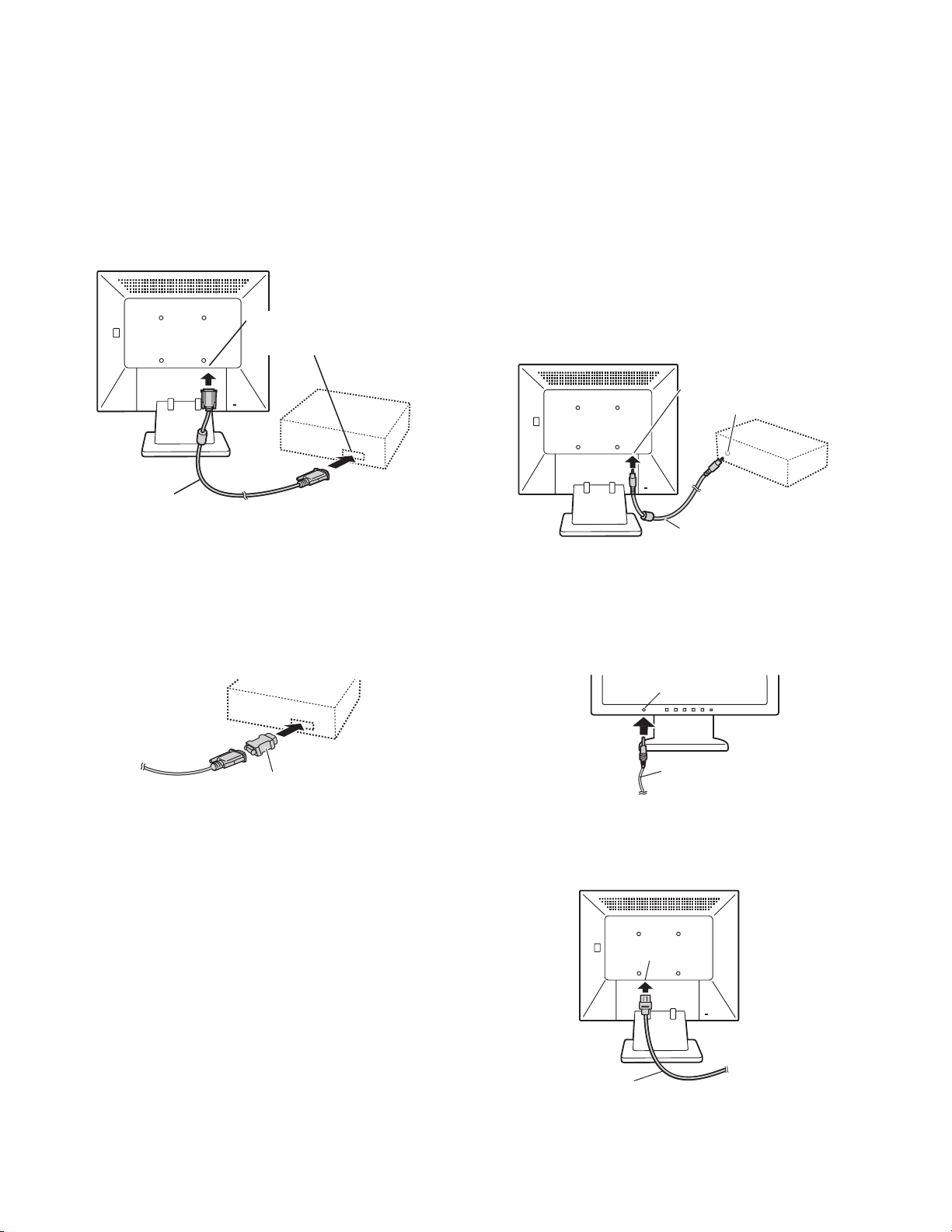
1-1. Connecting the monitor to a computer
Analog RGB terminal
(Mini D-sub 15 pin, 3 row)
Analog signal cab le
• Paying att ention to connector direction, firmly insert the signal cable
vertically into the connector, and then tighten the screws at both
sides.
If connecting to a D-sub 15 pin 2 row Apple P ower Macint osh, attach a
Macintosh conversion adapter (commercially available) to the analog
signal cable.
■ Connect the accessory audio cable
When the accessory audio cable is connected to the audio output terminal of the computer, the sound of the connected computer is output
from the monitor speakers. You can also use the headphone jack of the
display.
Audio input terminal
Audio output ter minal
Audio cable
1-2. Connection of headphones
(commercially available)
Headphones (commercially available) can be connected.
Headphone ter minal
Macintosh conversion adapter
Note: If connecting to the Sun Ultra series, a conversion adapter (com-
mercially available) may be required.
LL-T17A4-H/B CONNECTION, ADJUSTMENT, OPERATION, AND FUNCTIONS
Headphones
Note: When the headphones are connected, no sound can be heard
from the monitor speakers.
1-3. Connecting the monitor to a power source.
Power terminal
Power cord
2 – 1
AC outlet
Page 6
1-4. Turning the power on
1. Turn on the main power of the monitor.
Main power switch
• When switching the main power switch on and off, always wait for an
interval of at least 5 seconds. Rapid switching may result in malfunction.
2.Press the monitor's power button.
The power LED will light up orange.
3.Turn on the computer.
Turn on the
computer power
Press power button.
supply.
ON
• When a signal is input from the computer, the power LED lights
up green, and the screen is displayed. (After power is turned on, it
may take a little time until the screen is displayed.)
Note:
• If using the monitor for the first time or after having changed the
system settings during use, perform an automatic screen adjustment.
• Depending on the type of computer or OS, you may need to
install the monitor set-up information on your system.
• When connecting to a notebook, if the notebook computer's
screen is set to display at the sam e time, the MS-DOS screen
may not be able to display properly. In this ca se, change th e settings so that only on the monitor.
1-5. Turning the power off
1. Turn the computer off.
2. Press the monitor's POWER button.
The Power LED will disappear.
Turn the
computer off.
Press power button.
OFF
If the monitor will not be used for a long time, turn off the main power
switch of the monitor, and remove the power plug from the outlet.
LL-T17A4-H/B CONNECTION, ADJUSTMENT, OPERATION, AND FUNCTIONS
2 – 2
Page 7
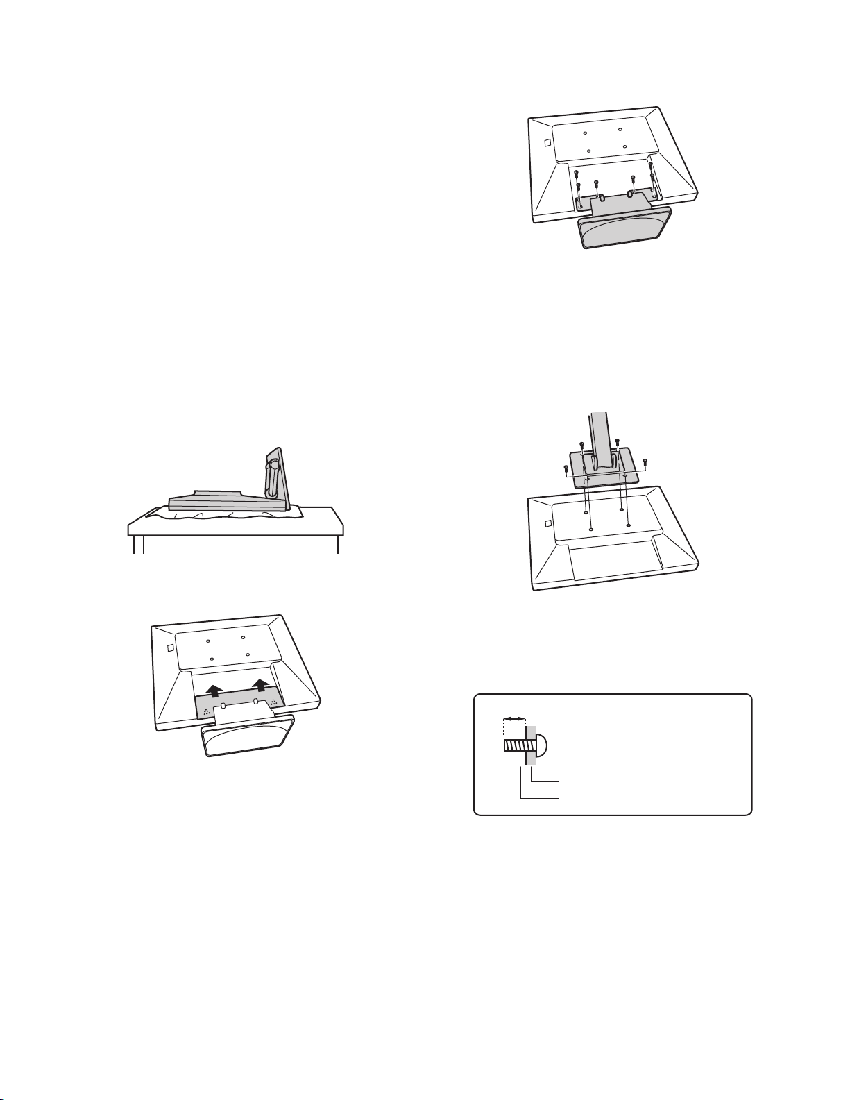
1-6. Instructions for attaching a VESA compliant arm
An arm or stand based on the VESA standar d (comme rcially available)
can be attached to the monitor.
Procurement of the arm or stand is at the customer's discretion.
Arms or stands able to be used
Attachments must satisfy the following.
• Compatible with the VESA standard
• Have a gap of 100 mm x 100 mm between the screw holes on the
section to be attached.
• Not be likely to fall off or break off after being attached to the monitor.
How to attach the arm or stand
• Be careful not to overly bend the cable or add extension cords as this
could lead to malfunction.
• While following these instructions, please also refer to the installation
instructions in the operation manual included with the arm or stand.
Caution: Be careful not to get your fingers pinched between the display
and stand nor to let the stand drop. These could lead to injury.
1. Remove the cables.
2. Spread out a soft cloth on a suitable horizontal surface.
3. Being careful not to damage the monitor, gently lay the monitor on it
display-side down.
5. Remove the six screws and then remove the stand from the monitor.
Note:
• The stand is specially made for use with this monitor. Once having
removed the stand, never attempt to attach it to another device.
• Once having removed the screws, store them together with the
stand and if the stand is ever re-attached be sure to use the original
screws.
Using different screws could lead to a malfunction.
6. Attach the arm to the monitor with the four screws.
4. Remove the cover.
• While pressing the A areas on the sides, push it up.
Note: The screws used to attach the arm should be M4 screws with a
length of 6 mm ~ 8 mm protruding from the surface to be
attached.
Using different screws could cause the monitor to fall off or to be
internally damaged.
6 - 8 mm
Screw used to attach arm
Arm
Part of monitor to which arm is attached
LL-T17A4-H/B CONNECTION, ADJUSTMENT, OPERATION, AND FUNCTIONS
2 – 3
Page 8
2. ADJUSTMENT
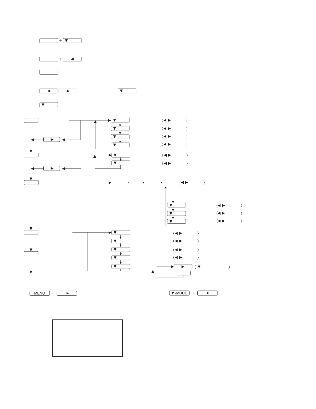
2-1. ADJUSTMENT METHOD
1) Resetting all adjustment values
MENU
Press the above two buttons at same time, and while turn the power on.
2) ADJUSTMENT menu reset
MENU
3) Adjustment lock function
MENU
While pressing the MENU button, turn the power on.
4) Adjusting the backlight and speaker volume
5) Setting display mode
/MODE
6) Screen adjustment
MENU
ADJUSTMENT
AUTO
/MODE
Power ON
Press the two buttons at same time.
Power ON
buttons (Press the button and select "BRIGHT" or "VOLUME".)
button (STD, OFFICE, sRGB, VIVID)
/MODE
/MODE
/MODE
/MODE
/MODE
CLOCK
PHASE
H-POS
V-POS
buttons
buttons
buttons
buttons
MENU
GAIN CONTROL
/MODE
/MODE
BLACK LEVEL
CONTRAST
AUTO
MENU
MENU
MENU
MODE SELECT
WHITE BALANCE
(COOL STD
/MODE
/MODE
/MODE
/MODE
/MODE
OSD H-POSITION
OSD V-POSITION
SCALING
400 LINES
LANGUAGE
END
7) Version display (for service)
Power ON.
Display the software version.
Press the above two buttons at same time, and while turn the power
on.
MODEL NAME : LL-T17A4E
VERSION : V1.000
DATE : 23/05/2003
CHECK SUM : 595D
V-Sync : 75 Hz
H-Sync : 46 kHz
buttons
buttons
WARM USER)
/MODE
/MODE
/MODE
8) Aging (for service)
Press the d button, Screen color is changed as following.
Red 3 Green 3 Blue3 Yellow 3 P urple 3 Light Blue 3 White
3 Black
When the test is terminate, Power off
buttons
CONTRAST
(R/G/B)
R-CONTRAST
G-CONTRAST
B-CONTRAST
buttons
buttons
buttons
buttons
MENU
/MODE
buttons
buttons
buttons
buttons
Power ON
LL-T17A4-H/B CONNECTION, ADJUSTMENT, OPERATION, AND FUNCTIONS
2 – 4
Page 9

2-2. ADJUSTMENT ITEM LIST
BUTTON ITEM ADJUSTMENT DESCRIPTION
MENU MENU 1:
ADJUSTMENT
MENU 2:
GAIN CONTROL
MENU 1
4
MENU 2
MENU 3:
WHITE BALANCE
4
MENU 3
4
MENU 4
4
MENU END
MENU 4:
MODE SELECT
c/MODE Select the item
e d
POWER OFF
MANUAL CLOCK 0~255 CLOCK:Adjust so that vertical flicker noise is not emit-
ted. (e d buttons)
PHASE 0~31 PHASE: Adjust so that horizontal flicker noise is not
emitted. (e d
e d buttons)
e de d
H-POS 0~255 H-POS (horizontal positioning) and
V-POS 0~63
V-POS (vertical positioning)
To center the screen image within the boundaries of
the screen, adjust the left-right (H-POS) values a nd
the up-down (V-POS) values. (e d
AUTO Automatic screen adjustment
Options in the ADJUSTMENT Menu can be adjus ted
automatically
(CLOCK, PHASE, H-POS V-POS).
MANUAL BLACK LEVEL 0~63
BLACK LEVEL: Total screen brightness can be adjusted
while watching the color pattern.
e d
buttons)
(
CONTRAST 0~63 CONTRAST: While watching the color pattern,
adjustments can be made so that all
graduations appear. (e d
AUTO GAIN CONTROL Menu
AUTO:Every menu option is automatically adjusted
using the Auto Gain Control function.
COOL • STD • WARM
(5 levels),
USER R • G • B: 0~63
WHITE BALANCE Menu
COOL : Color tone bluer than standard
• : Color tone slightly bluer than standard
STD : Color tone standard setting
• : Color tone slightly redder than standard
WARM : Color tone redder than standard
USER
R-CONTRAST: e but ton for blue-green
d button for red
G-CONTRAST: e button for purple
d button for green
B-CONTRAST: e button for yellow
d button for blue
OSD H-POSITION
(OSD horizontal position)
OSD V-POSITION
(OSD vertical position)
SCALING
(Level of scaling)
0~2 SCALING (Level of scaling)
The position of the OSD display can be moved to the
left and right. (e d buttons)
The position of the OSD display can be moved up and
down. (e d buttons)
Adjusts the image to optimum sharpness when Screen
expansion is taken. (e dbuttons)
400 LINES
640, 720
(degree of resolution)
LANGUAGE 7 countrys
DEUTSCH, ENGL ISH,
ESPANOL, FRANCAIS,
ITALIANO, NETHERLAND, SVENSKA
sRGB, OFFICE, STD,
VIVID
You can specify the horizonal resolution of a 400 line
screen when using US text, etc. (e dbuttons)
LANGUAGE
Messages displayed on the screen and OSD Menu
contents can be changed to the following languages.
Dutch, English, French, German, Spanish, Italian,
Swedish.
Setting color mode when the ADJUSTMENT Menu is
not displayed.
STD: Displays image with the color tone results
from original scheme of liquid crystal panel.
OFFICE:Display brightness is lowered. The brightness
is set to a level that is easier on the eyes than
with other modes and saves power.
sRGB: sRGB is international standard of color repre-
sentation specified by IEC (International Electrotechnical Commission). Color conversion is
made in taking account of liquid crystals characteristics and represents color tone close to
it original image.
VIVID: Displays an image with dynamic and VIVID
primary colors.
Bright: 0~31
Volume: 0~22
Adjusting the backlight
Adjusting the speaker volume
e d buttons)
e de d
e d buttons)
e de d
LL-T17A4-H/B CONNECTION, ADJUSTMENT, OPERATION, AND FUNCTIONS
2 – 5
Page 10

CHAPTER 3. DISASSEMBLY AND ASSEMBLY
1. STAND UNIT REMOVAL
1) Remove the rear cover (A) by sli ding i t upwar d.
2) Remove the screws, and remove t he stan d unit (B).
B
2. I/F PWB REMOVAL
1) Remove the screws, and remove the rear cabine t.
3) Remove all the conn ectors an d flat cab les o n the PWB.
4) Remove the hex. screws, washer and screws, and remove the I/F
PWB by sliding it upward.
A
3. P/I PWB REMOVAL
1) Remove the connector covers (A), and remove all the connectors on
the PWB.
2) Remove the screws, an d remove the P/I PWB (B).
2) Remove the screws, and remove the shield by slid ing it upward.
A
B
A
4. LCD UNIT REMOVAL
1) Remove the screws, and remove the front cabinet (A).
2) Remove the screws, and remove the LCD unit (C) from the bracket
panel (B).
A
C
B
LL-T17A4-H/B DISASSEMBLY AND ASSEMBLY
3 – 1
Page 11

CHAPTER 4. BLOCK DIAGRAM
LCD MONITOR
LL-T17A4-H/B BLOCK DIAGRAM
4 – 1
Page 12

CHAPTER 5. TROUBLE SHOOTING
S
1. No Power
Is there 13V on C203
positive terminal ?
YES
Is there 5V on C205
positive terminal ?
YES
1. Is there 3.3V on C233 positeve
terminal ?
2. 2.5V on C213 positeve terminal ?
YES
IC400, IC300 failure.
1. IC202, D205 failure.
2. IC203, D206 failure.
NO
2. No Display on Screen (LED is green)
Is the backlight lighted ?
NO
Is there any voltage
waveform on IC201
PIn2 ?
YES
L201, D201 failure.
Is there 13V on CN201
connection ?
YES
F201, FB205
failure.
IC201 failure.
NO
NO
NO
Power board
failure.
YES
Check signal cable is fully connected to CN400
The s ignal cable
is disconnected
YE
1. IC40 0
Pin126,127H&V sync
2. IC400 Pin122
YES
Is there 5V on CN400
Pin 1~3
YES
400 failure
NO
NO
NO
NO
Check wire harness is fully connected
between the Lamp and P-I board
YES
The cable is desconnected
Check that C205 positive is
5V, CN01 pin8 is 5V
YES NO
Check IC01 pin15
IC02, IC03, IC04, IC05
T01, T02 failure
IC301, Q306 failure
NO
NO
IC01 failure
Panel cable, IC400
Panel failure
Q203 failure
LL-T17A4-H/B TROUBLE SHOOTING
5 – 1
Page 13

3. Show “No Signal ” on screen
Check CN602 Pin13, Pin14
NO
Check IC400 Pin127 same as
V-sync of input
YES
Check IC400 Pin126 same as
H-sync of input
YES
IC400 failure
4. color interference
(Test patern: 32 Gray 1280 x 1024@60Hz)
Signal cable is not
fully connected
NO
D619 failure
NO
D618 failure
Check signal cable fully connected between
signal source and Interface Board
YES
Check CN602 Pin1, 2, 3
RIN, GIN, BIN
IC400 failure
LL-T17A4-H/B TROUBLE SHOOTING
NO
The Signal cable not fully
connected
NO
D614, D615, D616 failure
5 – 2
Page 14

5. Function key can not work
YES
Check wire harness
is connected form I/F
board to Key
NO
Check voltage of IC301
pin38, 39, 40, 41, 42, 43 while key is
pressing
INPUT
MENU
MODE/DOWN
LEFT
RIGHT
Power-ON/OFF
YES
IC301 fail
ure
6. No Sound
(Test signal: Vrms sine waveform)
Check IC801 Pin15, 16 is approximately 12V
YES
The key cable is disconnected
NO
KeyBoard failure
NO
Adjust VOLUME to max and check
IC801 pin 14, 17
YES
Check wire harness is connected
from CN804, CN802 to earphone board
YES
Earphone output normal
The speakers are failure
D807 failure
NO
Check IC801 Pin 12 is Low voltage
YES
IC801failure
NO
The cable is deiconnected
NO
CN805 is failure
IC301failure
NO
LL-T17A4-H/B TROUBLE SHOOTING
5 – 3
Page 15

POWER + INVERTER
13V
CN101
CN102
CN103
F101
F102
FL102, FL101
CX101, R113
R109, R110, R111
CY102, CY103
EMT FILTER
F01, Q01, R03, D01, Q02
D11, R44, R31, R04, R19
REGULATOR & BROWN
OUT CIRCUIT
Q03, Q04, Q05, Q06,
R24, D07, D08
LAMP OUTPUT
SENSOR
13V
5V
VA101, V A104
VARISTOR
IC01
OZ960G
BURST MODE IC
OVP SENSOR
CR101
C101
RECTIFER
IC101
SG6841
PWM
CONTROLLER
IC02, IC03, T01
DRIVER
IC04, IC05, T02
DRIVER
T101, Q101
TRANSFORMER
DRIVER
D101, C103, C104
DC OUTPUT
R120, R122, R124, R125
C110, IC102, IC103
CN02
OUT PUT CONNECTOR
CN03
OUT PUT CONNECTOR
CN04
OUT PUT CONNECTOR
CN05
OUT PUT CONNECTOR
13V
LAMP
LAMP
LAMP
LAMP
LL-T17A4-H/B BLOCK DIAGRAM
4 – 2
Page 16

B
B
B
D
D
D
D
1/7
12345678
12345678
12345678
12345678
C
C
C
C
B
A
21
21
21
21
3
3
3
3
CHAPTER 6. CIRCUIT DIAGRAM
87654
87654
87654
87654
B
B
B
D
D
D
D
C
C
C
C
LL-T17A4-H/B CIRCUIT DIAGRAM
6 – 1
B
A A
A A
A A
A
Page 17

B
B
B
D
D
D
D
2/7
12345678
12345678
12345678
12345678
C
C
C
C
B
A
21
21
21
21
3
3
3
3
87654
87654
87654
87654
B
B
B
D
D
D
D
C
C
C
C
LL-T17A4-H/B CIRCUIT DIAGRAM
6 – 2
B
A A
A A
A A
A
Page 18

B
B
B
D
D
D
D
3/7
12345678
12345678
12345678
12345678
C
C
C
C
B
A
21
21
21
21
3
3
3
3
87654
87654
87654
87654
B
B
B
D
D
D
D
C
C
C
C
LL-T17A4-H/B CIRCUIT DIAGRAM
6 – 3
B
A A
A A
A A
A
Page 19

B
B
B
D
D
D
D
4/7
12345678
12345678
12345678
12345678
C
C
C
C
B
A
21
21
21
21
3
3
3
3
87654
87654
87654
87654
B
B
B
D
D
D
D
C
C
C
C
LL-T17A4-H/B CIRCUIT DIAGRAM
6 – 4
B
A A
A A
A A
A
Page 20

B
B
B
D
D
D
D
5/7
12345678
12345678
12345678
12345678
C
C
C
C
B
A
21
21
21
21
3
3
3
3
87654
87654
87654
87654
B
B
B
D
D
D
D
C
C
C
C
LL-T17A4-H/B CIRCUIT DIAGRAM
6 – 5
B
A A
A A
A A
A
Page 21

B
B
B
D
D
D
D
6/7
12345678
12345678
12345678
12345678
C
C
C
C
B
A
21
21
21
21
3
3
3
3
87654
87654
87654
87654
B
B
B
D
D
D
D
C
C
C
C
LL-T17A4-H/B CIRCUIT DIAGRAM
6 – 6
B
A A
A A
A A
A
Page 22

B
B
B
D
D
D
D
7/7
12345678
12345678
12345678
12345678
C
C
C
C
B
A
21
21
21
21
3
3
3
3
87654
87654
87654
87654
B
B
B
D
D
D
D
C
C
C
C
LL-T17A4-H/B CIRCUIT DIAGRAM
6 – 7
B
A A
A A
A A
A
Page 23

CHAPTER 7. PWB LAYOUT
1. MAIN PWB
A side
B side
LL-T17A4-H/B PWB LAYOUT
7 – 1
Page 24

2. POWER SUPPLY PWB
A side
B side
LL-T17A4-H/B PWB LAYOUT
7 – 2
Page 25

q
COPYRIGHT
No part of this publication may be reproduced,
electronic, mechanical, photocopying, recording, or otherwise,
without prior written permission of the publisher.
2003 BY SHARP CORPORATION
All rights reserved.
Printed in Japan.
stored in a retrieval system, or transmitted.
In any form or by any means,
SHARP CORPORATION
Digital Document Systems Group
Products Quality Assurance Department
Yamatokoriyama, Nara 639-1186, Japan
2003 July Printed in Japan t
 Loading...