

Page 1
SERVICE MANUAL
LCD COLOR MONITOR
MODEL LL-T1610W
CONTENTS
CHAPTER 1. OUTLINE OF THE PRODUCT,
NOMENCLATURE AND FUNCTION.................. .. .................... .1
CHAPTER 2. CONNECTION, ADJUSTMENT,
OPERATION AND FUNCTIONS................................................5
CHAPTER 3. DISSASEMBLY AND REASSEMBLY......................................16
CHAPTER 4. TROUBLE SHOOTING ............................................................18
CHAPTER 5. HARDWARE ............................................................................20
CHAPTER 6. CIRCUIT DIAGRAM.................................................................23
CHAPTER 7. PARTS LAYOUT......................................................................30
Parts marked with " " are important for maintaining the safety of the set. Be sure to replace these parts with specified
ones for maintaining the safety and performance of the set.
This document has been published to be used
SHARP CORPORATION
for after sales service only.
The contents are subject to change without notice.
Page 2
Symbol/PartsCod)
- - - - - - - - - - - - - - - - - - - - - - - - - - - - - - - - - - - - - - - - - - - - - - - - - - - - - - -
CHAPTER 1. OUTLINE OF THE PRODUCT, NOMENCLATURE AND FUNCTION
1. SPECIFICATIONS
■ PRODUCT SPECIFICATIONS
•
LCD display
40 cm measured diagonally
Anti Glare Low Reflection TFT LCD module
• Resolution (max.)
SXGA 1280 x 1024
• Displayable colors (max.)
Approximately 16.77 million colors (8 bit)
• Brightness (max.)
230cd/m
2
• Dot pitch
0.248(H) 0.248(V) mm
• Contrast ratio
300:1
• Angle of visibility
Left-right 160° ; Up-down 130°
• Screen display size
Horizontal 317.8 mm x Vertical 254.2 mm
• Video signal
Analog: Analog RGB (0.7Vp-p) [75Ω]
Digital: DVI standard based on 1.0
• Sync signal
Separate Sync (TTL level: +/-), Sync on Green,
Composite Sync (TTL level: +/-)
• Expansion compensation
Digital screening (enlargement of display to correct VGA / SVGA /
XGA)
• Plug & Play
VESA: DDC1/DDC2B compatible
• Power management
VESA: based on DPMS
DVI: based on DMPM
• Input signal terminal
Analog: 15 pin mini D-sub (3 rows)
Digital: 24 pin DVI-D
• USB hub function
1 upstream port, 2 downstream ports (bus-powered hub based on
USB standard Rev 1.1)
• Screen angle adjustment
Tilt: Upward: 0° - 30°
Swivel: Total from left through right: 90° (turntable form)
• Power supply
AC100-240V, 50/60Hz (Use special AC adapter, type NL-A54J of
Sharp Corporation.)
• Temperature of operating environment
5 - 35°C
• Power consumption
Maximum 32W (approximately 3W when in power-saving mode)
(Use special AC adapter.)
• Dimensions (excluding rubber base)
377 mm (W) x 180 mm (D) x 390 mm (H)
• Weight
Approx. 5.4 kg (excluding AC adapter)
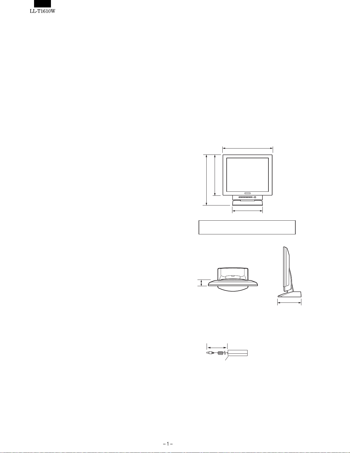
■ DIMENSIONS (Units: mm)
377
310
390
230
Length of analog signal cable: approx. 1.8 m*
Length of USB cable included: approx. 1.8 m
*Length from analog signal input terminal
45
180
Special AC adapter
Approx. 2.0 m
Approx. H 125 mm u D 60 mm u H 33 mm
Page 3
Relevant signal timings (analog)
Relevant signal timings (digital)
Display mode Hsync (kHz) Vsync (Hz) Dot frequency (MHz)
VESA 640 x 480 31.5kHz 60Hz 25.175MHz
37.9kHz 72Hz 31.5MHz
37.5kHz 75Hz 31.5MHz
43.3kHz 85Hz 36.0MHz
640 x 400 37.9kHz 85Hz 31.5MHz
720 x 400 37.9kHz 85Hz 35.5MHz
800 x 600 35.1kHz 56Hz 36.0MHz
37.9kHz 60Hz 40.0MHz
48.1kHz 72Hz 50.0MHz
46.9kHz 75Hz 49.5MHz
53.7kHz 85Hz 56.25MHz
1024 x 768 48.4kHz 60Hz 65.0MHz
56.5kHz 70Hz 75.0MHz
60.0kHz 75Hz 78.75MHz
68.7kHz 85Hz 94.5MHz
1152 x 864 67.5kHz 75Hz 108.0MHz
1280 x 960 60.0kHz 60Hz 108.0MHz
1280 x 1024 64.0kHz 60Hz 108.0MHz
80.0kHz 75Hz 135.0MHz
US text 720 x 400 31.5kHz 70Hz 28.3MHz
Power
Macintosh
series
Sun Ultra
series
640x480 35.0kHz 66.7Hz 30.2MHz
832 x 624 49.7kHz 74.6Hz 57.3MHz
1024 x 768 60.2kHz 75Hz 80.0MHz
1152 x 870 68.7kHz 75Hz 100.0MHz
1024 x 768 48.3kHz 60Hz 64.13MHz
53.6kHz 66Hz 70.4MHz
56.6kHz 70Hz 74.25MHz
1152 x 900 61.8kHz 66Hz 108.01MHz
71.8kHz 76.1Hz 117.01MHz
1280 x 1024 71.7kHz 67.2Hz 117.01MHz
81.1kHz 76Hz 134.99MHz
• All are compliant only with non-interlaced.
• Frequencies for Power Macintosh and the Sun Ultra series are
reference values. To connect, another adapter (purchased separately) may be required.
• If the monitor is receiving timing signals that are not compatible,
[OUT OF TIMING] will appear. Follow your computer’s instruction
manual to set the timing so that it is compatible with the monitor.
• If the monitor is not receiving any signal (synch signal), [NO SIG-
NAL] will appear.
Display mode Hsync (kHz) Vsync (Hz) Dot frequency(MHz)
VESA 640 x 480 31.5kHz 60Hz 25.175MH
37.9kHz 72Hz 31.5MHz
37.5kHz 75Hz 31.5MHz
800 x 600 37.9kHz 60Hz 40.0MHz
48.1kHz 72Hz 50.0MHz
46.9kHz 75Hz 49.5MHz
1024 x 768 48.4kHz 60Hz 65.0MHz
56.5kHz 70Hz 75.0MHz
60.0kHz 75Hz 78.75MHz
1152 x 864 67.5kHz 75Hz 108.0MHz
1280 x 960 60.0kHz 60Hz 108.0MHz
1280 x 1024 64.0kHz 60Hz 108.0MHz
US text 720 x 400 31.5kHz 70Hz 28. 3MHz
• All are compliant only with non-interlaced.
• A computer with an output terminal conforming to DVI (DVI-D24
pin or DVI-I29 pin) and with SXGA output capability can be connected here. Depending on the type of computer to be connected,
the display may not work correctly. In order to connect, it is necessary to purchase a digital signal cable (model name: NL-C01E)
separately.
• If the monitor is receiving timing signals that are not compatible,
[OUT OF TIMING] will appear. Follow your computer’s instruction
manual to set the timing so that it is compatible with the monitor.
• If the monitor is not receiving any signal (synch signal), [NO SIG-
NAL] will appear.
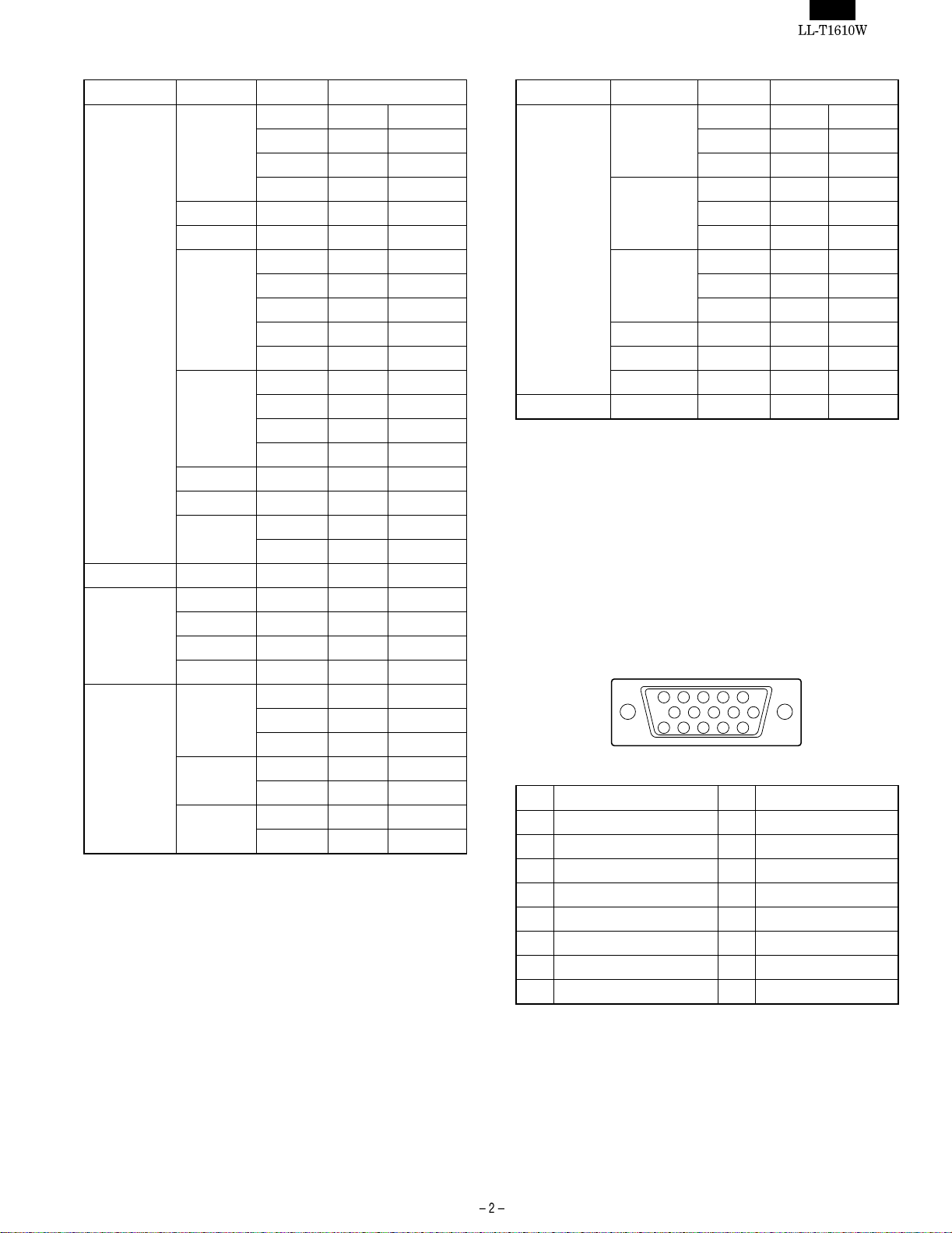
The analog signal input connector pin
10
15 11121314
(Mini D-sub connector with 15 pins)
No. Function No. Function
1 Red video signal input 9 DDC/VCC
2 Green video signal input 10 GND
3 Blue video signal input 11 N.C.
4 GND 12 DDC data
5 GND 13 For Hsync signal input
6 For red video signal GND 14 For Vsync signal input
7 For green video signal GND 15 DDC clock
8 For blue video signal GND
25134
6789
Page 4
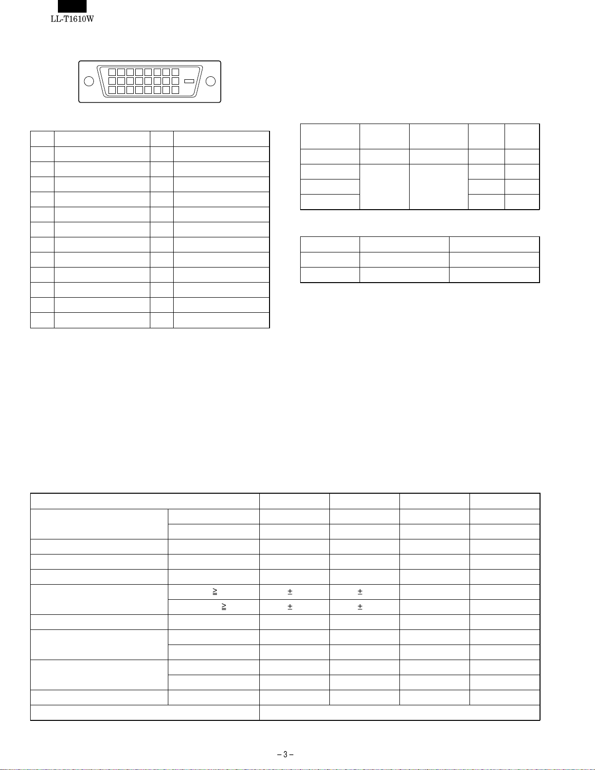
The digital signal input connector pin
1 7
9
17 23
(DVI-D connector with 24 pins)
5432 8
6
151413121110 16
21201918 24
22
Power management
The monitor is based on the VESA DPMS*1 and the DVI DMPM*2
standards.
To activate the monitor’s Power Management function, both the video
card and the computer must conform to the VESA DPMS standard
and the DVI DMPM standard.
*1 DPMS: Display Power Management Signalling
No. Function No. Function
1 TMDS data 2- 13 N.C.
2 TMDS data 2+ 14 +5V
3 TMDS data 2 shield 15 GND
4 N.C. 16 Hot plug detection
5 N.C. 17 TMDS data 06 DDC clock 18 TMDS data 0+
7 DDC data 19 TMDS data 0 shield
8 N.C. 20 N.C.
9 TMDS data 1- 21 N.C.
10 TMDS data 1+ 22 TMDS clock shield
11 TMDS data 1 shield 23 TMDS clock +
12 N.C. 24 TMDS clock -
DPMS mode Screen
Power
consumption
H-sync V-sync
ON Display on 32W Yes Yes
STANDBY Display off 1.5W No Yes
SUSPEND Yes No
OFF No No
*2 DMPM: Digital Monitor Power Management
DPMS mode Screen Power consumption
ON Display on 32W
OFF Display off 3W
DDC (Plug & Play)
This monitor supports the VESA DDC (Display Data Channel) standard.
DDC is a signal standard for carrying out Plug & Play functions on the
monitor or PC. It transfers information such as degree of resolution
between the monitor and PC. You can use this function if your PC is
DDC compliant and if it is set so that it can detect the Plug & Play
monitor.
There are many varieties of DDC due to the differences between
systems. This monitor works with DDC1 and DDC2B.
2. TECHNICAL SPECIFICATIONS
Item MIN TYP MAX Unit
Power supply voltage AC 90 100 264 V
DC 12.0 12.5 13.0 V
Working temperature range +5 – +35 °C
Storing temperature range -20 – +60 °C
Humidity range 20 – 85 %RH
Visual angle range Vertical (CR
Horizontal (CR
Contrast ratio (CR) (θ = 0°) 230 300 – –
Response speed Leading (τr) – 10 25 ms
Trailing (τd) – 35 50 ms
Screen white chromaticity (X) 0.273 0.303 0.333 –
(Y) 0.289 0.319 0.349 –
White surface luminance (Y
) 190 230 – cd/m
L
Module model number LQ160E1DR10
5) 45 65 – Temperature
5) 60 80 – Temperature
2
Page 5

3. PRODUCT DESCRIPTION
Front view Rear view
1 2 3 4 5 6
7 8 9
10
1. INPUT button
Use this button to switch between input signals.
(analog
digital)
2. MENU button
This button is used to pop-up, select and close the On Screen
Display (OSD) Menu.
3. SELECT button
Selects the menu option to be adjusted.
4.
buttons
These buttons are used to adjust backlight brightness. When the
OSD Menu is displayed these buttons are used to increase or
decrease the value of a selected option.
5. Power LED
This LED is lit green when in use and orange when in power-
saving mode.
6. Power button
Pressing this button turns the power on. (After turning the power
on, it may take a little time before the screen displays.)
Press the button again to turn the power off.
7. Security lock anchor
By connecting a security lock (purchased separately), the moni-
tor is fixed so that it cannot be transported.
12. Digital signal input terminal
13
Remove the rear cover to see the digital signal input terminal
(DVI-D24 pin). Use this when connecting to the PC’s digital RGB
output terminal.
A computer with an output terminal conforming to DVI (DVI-D24
pin or DVI-I29 pin) and with SXGA output capability can be
connected here. Depending on the type of computer to be con-
12
11
nected, the display may not work correctly. In order to connect, it
is necessary to purchase a digital signal cable separately.
(model name: NL-C01E)
13. Ventilation openings
Note: Never block the ventilation openings as this may lead to
overheating inside the monitor and result in malfunction.
Security lock anchor
By connecting a security lock (purchased separately) to the security
lock anchor, the monitor is fixed so that it cannot be transported.
The security slot works in conjunction with Kensington Micro Saver
Security Systems.
8. Power terminal
Remove the rear cover to see the power terminal. The AC
adapter supplied is connected here.
9. Analog signal input terminal
Remove the rear cover to see the analog signal input terminal.
At the time of leaving the factory the analog signal cable is
connected.
10. Analog signal cable
Connects to the computer’s analog RGB output terminal.
11. USB port
Remove the rear cover to see the USB port (upstream: 1 port,
downstream: 2 ports).
Page 6
CHAPTER 2. CONNECTION, ADJUSTMENT, OPERATION AND FUNCTIONS
1. CONNECTING THE MONITOR AND
TURNING THE MONITOR ON AND OFF
1-1. CONNECTING THE MONITOR TO A POWER
SOURCE
Use only the AC adapter and power cord supplied.
• Do not overly bend the cable or add extension cords as
Notes:
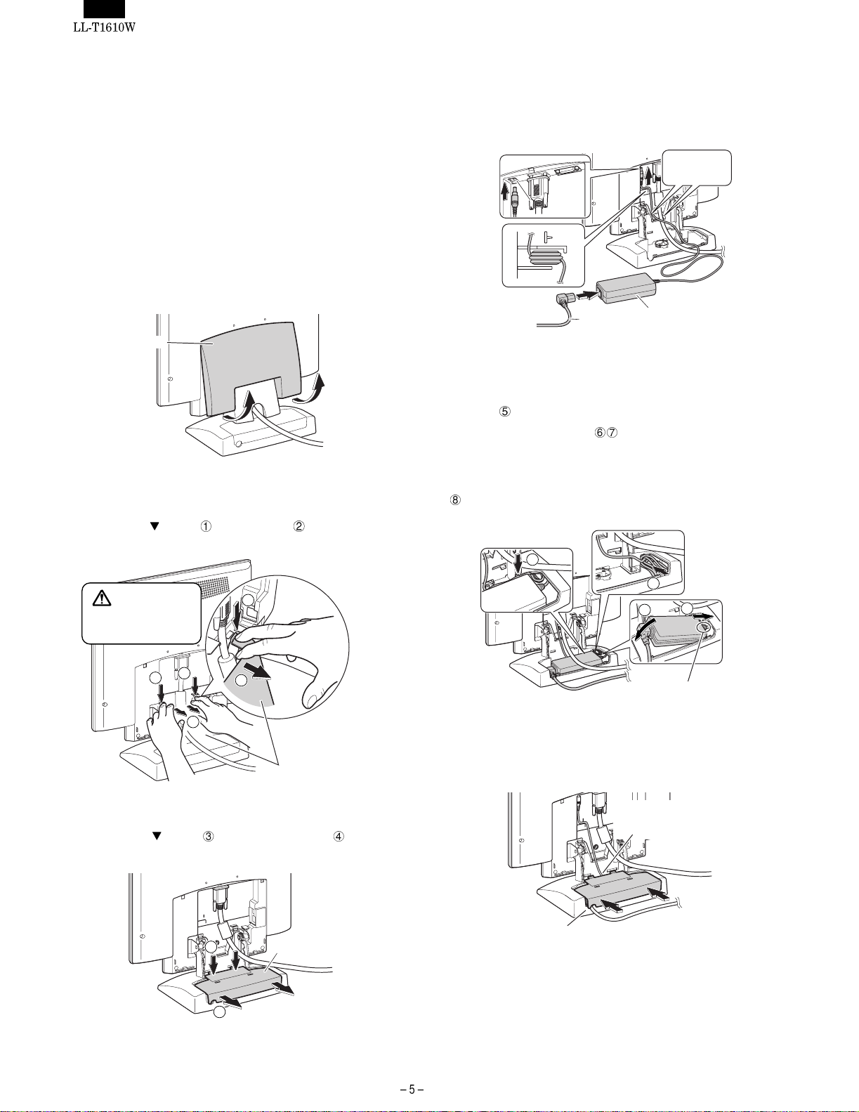
1. Remove the rear cover.
2. Remove the stand cover.
this could lead to malfunction.
• Do not remove the label next to the power-input terminal.
Also do not touch the switch covered by the label.
Rear cover
As in the diagram below, place two fingers on the stand cover and
while pushing the
section , pull it forwards .
4. Connect the AC adapter to the monitor’s power terminal, and
connect the power cord to the AC adapter.
Run cord
through hole
Power cord
5. Place the AC adapter inside the stand.
Wind the AC adapter cable and place it in the right-hand end of
the stand
Place the AC adapter inside
to place the AC adapter on top of the cable as this will make it
difficult to replace the adapter cover.
Run the AC adapter cable between the AC adapter and the stand
.
.
AC adapter
. When doing this be careful not
CAUTION!
Be careful not to
cut or jam your
fingers.
1
1
3. Remove the adapter cover.
While pushing the
section , pull it forwards and off .
8
5
1
2
2
6. Replace the adapter cover.
Stand cover
3
Adapter cover
Run the powerr cord through here.
7
Note: Take care not bend
Run the AC adapter
cord through here.
6
or twist the cord
4
Page 7
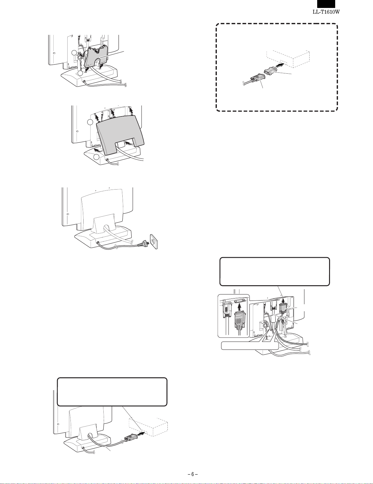
7. Replace the stand cover.
10
Run the analog signal
cable through here.
If connecting to a D-sub 15 pin 2 row Apple Pow er
Macintosh, attach a Macintosh conversion adapter (to
be purchased separately) to the analog signal cable.
9
8. Replace the rear cover.
11
12
9. Place power plug into AC outlet.
Macintosh
conversion adapter
Analog signal cable
After connecting the adapter, tighten the
screws on each side to fix into place
Note: If connecting to the Sun Ultra series, a conversion adapter
(purchased separately) may be required.
For digital RGB output te rminal
Connecting to a computer with digital RGB output. When connecting,
ensure that both the monitor and computer are switched off.
Notes:
• A computer with an output terminal conforming to DVI
(DVI-D24 pin or DVI-I29 pin) and with SXGA output capability can be connected here. Depending on the type of
computer to be connected, the display may not work correctly. In order to connect, it is necessary to purchase a
digital signal cable separately. (model name: NL-C01E)
• Be caref ul not to overly bend the cable or add extension
cords as this could lead to malfunction.
1. Remove the rear cover and the stand cover.
To remove them follow steps 1 and 2 of Connecting the monitor
to a power source.
2. Attach the digital signal cable (sold separately from monitor).
1-2. CONNECTING THE MONITOR TO A
COMPUTER (PC ETC.)
For analog RGB output terminal
Connecting to a computer with analog RGB output. When connecting,
ensure that both the monitor and computer are switched off.
Notes:
• If using the monitor for the first time or after having
changed the system settings during use, perform an automatic screen adjustment.
• Be careful not to overly bend the cable or add extension
cords as this could lead to malfunction.
• When connecting to a notebook, if the notebook com-
puter’s screen is set so that it is displaying at the same
time, the MS-DOS screen may not be able to display
properly. In this case, change the settings so that only the
monitor is displaying.
Analog RGB output terminal (mini D-sub 15 pin
with 3 rows)
Firmly insert the plug then tighten the screws
each side.
Computer
Digital signal input terminal (DV-D24 pin)
Firmly insert the plug than tighten the screws
each side.
Digital signal cable
Analog signal cable
Run cable through hole
If you are not using the analog signal cable, you can remove it.
Loosen all screws on the plug and disconnect it.
Analog signal cable
Page 8
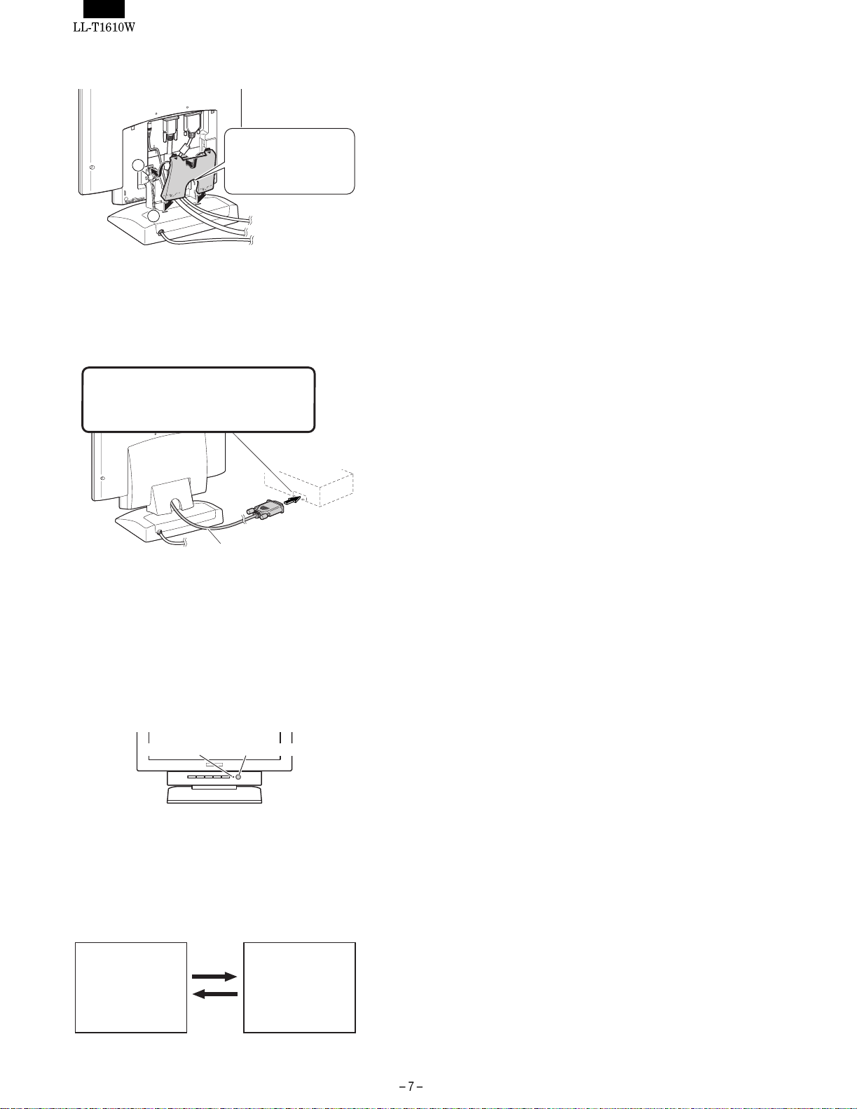
3. Replace the stand cover.
Run the digital signal
2
1
4. Replace the rear cover.
To replace it follow step 8 of Connecting the monitor to a power
source.
5. Connect the digital signal cable to the computer.
Digital RGB output terminal (DVI-D24 pin
or DVI-129 pin)
Firmly insert the plug then tighten the
screw each side.
Note: After turning the monitor on, use the INPUT button to switch
the incoming signal over to DIGITAL.
cable or the analog
signal cable through
here
Computer
Digital signal cable
1-3. TURNING THE POWER ON
1. Press the monitor’s power button.
2. Turn on the computer.
The power LED will be lit green, and the screen will display an
image.
Power LED Power button
Switching between input signals
To obtain the desired signal use the INPUT button to switch over to it.
Within a matter of seconds the signal type will be displayed on the
upper right-hand part of the screen.
Analog signal Digital signal
ANALOG
INPUT
INPUT
DIGITAL
Installing set-up information and the ICC profile
(Windows)
Depending on the computer or OS, it may be necessary to use the
computer to operate the installation of monitor set-up information etc.
If so, follow the steps below to install the monitor set-up information.
(Depending on the type of computer or OS, command names and
methods may differ. Please follow the computer’s own operation
manual while reading this.)
About the ICC profile
An ICC (International Color Consortium) profile is a file that describes
the color characteristics of the LCD monitor. By using an application
that works together with an ICC profi le, a high color resolution can be
realized.
• Windows98, WindowsMe and Windows2000 all use the ICC pro-
file.
• When installing Windows98, WindowsMe and Windows2000 set-
up information (described below), the ICC profile is also installed. If
you would like to install the ICC program only, please refer to
Installing the ICC profile.
• When using the I CC profile, please set the [WHITE BALANCE] to
[STD] and the [COLOR MODE] to [OFF].
■ For Windows95
Installing monitor set-up information into Windows95.
This explanation assumes that the floppy disk drive is "A drive".
1. Place the Utility Disk (provided) into the computer’s A drive.
2. Click on the [Start] button. From [Settings], choose [Control
Panel].
3. Double click on [Display].
4. Click on [Settings], [Advanced Properties], and [Monitor], then
[Change].
5. Click on [Have disk], confirm that [Copy manufacturer’s files
from:] is [A:] then click [OK].
6. Confirm that the monitor details are selected, and click [OK].
7. Check that the monitor details are displayed, then click [Apply].
8. Click [OK], and close the window.
9. Remove the Utility Disk from the A drive.
■ For Windows98
Installing monitor set-up information into Windows98, and setting the
monitor’s ICC profile as a predetermined value.
This explanation assumes that the floppy disk drive is "A drive".
If the "Add new Hardware Wizard" has appeared:
1. Place the Utility Disk (provided) into the computer’s A drive.
2. Click [Next].
3. Check [Display a list of all the drivers in a specific location, so
you can select the driver you want.], then click [Next].
4. When [Models] is displayed, click on [Have disk], confirm that
[Copy manufacturer’s files from:] is [A:], and click [OK].
5. Confirm that the m onitor details are selected, then click [Next],
[Next], and [Finish]. If the "Add New Hardware Wizard" appears,
repeat the installation commands beginning from 2 above.
6. Remove the Utility Disk from the A drive.
If the "Add New Hardware Wizard" has not appeared:
1. Place the Utility Disk in the computer’s A drive.
2. Click on the [Start] button. From [Settings], choose [Control
Panel].
3. Double click on [Display].
Page 9

4. Click on [Settings], [Advanced] and [Monitor].
5. In [Options] , check [Automatically detect Plug & Play monitors]
and click on [Change].
6. Click [Next].
7. Click on [Display a list of all the drivers in a specific location, so
you can select the driver you want.], then click [Next].
8. When [Models] is displayed, click on [Have disk], confirm that
[Copy manufacturer’s files from:] is [A:], and click [OK].
9. Confirm that the m onitor details are selected, then click [Next],
[Next], and [Finish].
10. Check that the monitor details are displayed, then click [Apply].
11. Click [OK], and close the window.
12. Remove the Utility Disk from the A drive.
■ For Windows2000
Installing monitor set-up information into Windows2000, and setting
the monitor’s ICC profile as a predetermined value.
This explanation assumes that the floppy disk drive is "A drive".
1. Place the Utility Disk (provided) into the computer’s A drive.
2. Click on the [Start] button. From [Settings], choose [Control
Panel].
3. Double click on [Display].
4. Click on [Settings], [Advanced] and [Monitor].
5. Click on [Properties], [Driver] and [Update Driver].
6. When [Upgrade Device Driver Wizard] appears, click [Next].
7. Check [Display a l ist of the known drivers for this device so that I
can choose a specific driver] and click [Next].
8. When [Models] is displayed, click on [Have disk], confirm that
[Copy manufacturer’s files from:] is [A:], and click [OK].
9. Select the monitor from the list displayed and click [Next].
10. Click [Next], confirm that the monitor’s name appears on the
screen, and click [Finish]. If [The Digital Signature Not Found]
appears, click [Yes].
11. Click on [Close].
12. Click [OK], and close the window.
13. Remove the Utility Disk from the A drive.
■ For WindowsMe
Installing monitor set-up information into WindowsMe, and set ting the
monitor’s ICC profile as a predetermined value.
This explanation assumes that the floppy disk drive is "A drive".
If the "Add new Hardware Wizard" has appeared:
1. Place the Utility Disk (provided) into the computer’s A drive.
2. Check [Specify the location of the driver [Advanced]] and click
[Next].
3. Check [Display a list of all the drivers in a specific location, so
you can select the driver you want.], then click [Next].
4. When [Models] is displayed, click on [Have disk], confirm that
[Copy manufacturer’s files from:] is [A:], and click [OK].
5. Select the moni tor details from the list, then click [Next], [Next],
and [Finish]. If the "Add new Hardware Wizard" appears, repeat
the installation commands beginning from 2 above.
6. Remove the Utility Disk from the A drive.
If the "Add New Hardware Wizard" has not appeared:
1. Place the Utility Disk in the computer’s A drive.
2. Click on the [Start] button. From [Settings], choose [Control
Panel].
3. Double click on [Display].
4. Click on [Settings], [Advanced] and [Monitor].
5. In [Options] , check [Automatically detect Plug & Play monitors]
and click on [Change].
6. Check [Specify the location of the driver [Advanced]] and click
[Next].
7. Check [Display a list of all the drivers in a specific location, so
you can select the driver you want.] and click [Next].
8. When [Models] is displayed, click on [Have disk], confirm that
[Copy manufacturer’s files from:] is [A:], and click [OK].
9. Select the monitor details, then click [Next], [Next] , and [Finish] .
10. Check that the monitor details are displayed, then click [Apply].
11. Click [OK], and close the window.
12. Remove the Utility Disk from the A drive.
Installing the ICC profile
Installing the monitor’s ICC profile. (If the set-up inform ation has already been installed, so too has the profile, and there is no need to
install it.)
This explanation assumes that the floppy disk drive is "A drive".
1. Place the Utility Disk in the computer’s A drive.
2. Click on the [Start] button. From [Settings], choose [Control
Panel].
3. Double click on [Display].
4. Click on [Settings] and [Advanced].
5. Click on [General] and from [Compatibility] select [Apply the new
display setting without restarting], then click on [Color Management].
1
6. Click [Add], and select [3
7. Choose the color profile that you would like to install, and click
on [Add].
8. Choose the profile and click on [Set As Default].
9. Click [OK], and close the window.
10. Remove the Utility Disk from the A drive.
/2 Floppy [A:]] as the file location.
• When using the I CC profile, please set the [WHITE BALANCE] to
[STD] and the [COLOR MODE] to [OFF].
Information about the ColorSyn c profile (MacOS)
About the ColorSync profile
ColorSync is the Apple Corporation’s color management system and
is a function that enables color resolution to be realized when used
with a compatible application. A ColorSync profile describes the color
characteristics of the LCD monitor.
Notes:
• Thi s monitor’s ColorSync profile works with MacOS8.5 or
above.
• When using the ColorSync profile, please set the [WHITE
BALANCE] to [STD] and the [COLOR MODE] to [OFF].
Page 10

Setting up the ColorSync profile
Notes: • A floppy disk drive is necessary. In addition, it is neces-
sary to have PC Exchange or File Exchange installed in
your system.
• Depending on the type of computer or OS, command
names and methods may differ. Please follow the computer’s own operation manual while reading this.
1. Place the Utility Disk (provided) into the computer’s floppy disk drive.
2. Copy the profile to be used from t he Mac folder on the Ut ility Disk
to the ColorSync profile folder located within the system folder.
3. Using the ColorSync on the control panel, choose the profile to be used.
1-4. TURNING THE POWER OFF
1. Turn the computer off.
2. Press the monitor’s power button.
The Power LED will disappear.
If the monitor is not going to be used for a long period of time, be
sure to unplug it from the AC outlet.
1-5. CONNECTING A USB DEVICE
This monitor is manufactured to work with a bus-powered hub that is
compatible with the USB standard (based on Rev.1.1).
Downstream (2 ports)
A USB device for currents of up to 100mA can be connected.
(Devices that exceed 100mA and USB hubs with bus-powered
specifications cannot be connected.)
Upstream (1 port)
A USB compatible computers or USB hub with self-powered
specifications is connected here. (USB hubs with bus-powered
specifications cannot be connected.)
Notes:
• Before connecting, ensure that the shape of the USB ca-
ble connector is correct.
• For inform ation regarding the USB function (such as set-
up) please refer to the operation manual of the computer
to be connected.
• Some computers, OS and other devices may not be able
to be activated. To ascertain a certain device’s USB compatibility, please contact the manufacturer of the device.
1. Remove the rear cover and the stand cover.
To remove them follow steps 1 and 2 of Connecting the monitor
to a power source.
2. Plug the USB cable (provided) into the monitor’s USB upstream port.
3. Connect the second USB cable (provided) to the comput er or the
USB downstream port.
USB upstream port
USB cable (provided)
Run through hole
To the computer or another
USB hub's downstream port
4. Plug the USB device into the monitor’s USB downstream port.
USB downstream port
USB device
Run through hole
5. Replace stand cover.
Run signal cable
2
1
6. Replace rear cover.
To replace it follow step 8 of Connecting the monitor to a power
source.
and USB cable
through here
2. ADJUSTMENT
2-1. BEFORE ADJUSTING THE SCREEN DISPLAY
■ About screen ad justment
The method of adjustment differs depending on whether the analog
signal or the digital signal is being used.
For analog signal
1. First perform an automatic adjustment.
2. Perform manual adjustment where necessary.
For digital signal
The monitor can generally be used without adjustment. If necessary
perform manual adjustment.
Note: The OS D c o n te nt s a re s a v e d e ve n a ft e r th e po w er i s tu r ned off.
However, if the power is turned off while the OSD menu is
displayed, the contents are not saved.
■ Resetting all adjustm en t val ue s
All adjustment values can be returned to their original ex-factory values in one command.
1. Press the power button to turn off the monitor power.
2. Press the MENU button and the SELECT button simultaneously, and
while doing this press the power button (i.e. turn the monitor on).
Continue to press the button until [ALL RESET] appears on the
screen. When [ALL RESET END] appears the reset is complete.
Page 11

3. After the reset has been completed, press the power button to
turn off the power.
4. After a period of several seconds press the power button to turn
the monitor back on.
Notes:
• While [ALL RESET] is displayed, the control buttons do
not function.
• It is not possible to reset values when the adjustment lock
is in place. Remove the adjustment lock before attem pting
to operate control buttons.
■ Adjustment lock function
By disabling the control buttons (i.e. setting the lock) any attempted
changes to adjusted values will be avoided.
1. Press the power button to turn off the monitor power.
2. While pressing the MENU button, press the power but ton (i.e. turn
the power on).
Continue to press the button until the message appears on the
screen.
When the menu is unlocked:
[ADJUSTENT LOCKED] will appear on the screen, and the lock
will be set.
When the menu is locked:
[ADJUSTENT UNLOCKED] will appear on the screen, and the
lock will be removed.
Note: When the lock is in place, all buttons other than the power
button are disabled.
■ Choosing a langu ag e for me ss ages
Messages displayed on the screen and OSD Menu contents can be
changed to the following languages.
Dutch, English, French, German, Italian, Spanish, Swedish.
1. Press the power button to turn the monitor off.
2. Pressing the
button (i.e. turn the monitor on).
Continue pressing the button until the Language Selection Menu
(LANGUAGE) is displayed on the screen.
3. Use the SELECT button to choose a language.
4. Press the MENU button.
The setting is complete. From now, messages and adjustment
menus will be displayed in the chosen language.
Note: The language selection menu disappears approximately 30
seconds after the last command has been made.
and buttons simultaneously, press the power
2-2. ADJUSTING THE SCREEN DISPLAY
(WHEN USING AN ANALOG SIGNAL)
(1) AUTOMATIC SCREEN ADJUSTMENT
Options in the ADJUSTMENT Menu can be adjusted automatically
(CLOCK, PHASE, H-POS V-POS).
Note: When setting up this monitor for the first time or after having
changed an aspect of the current system, perform an automatic screen adjustment before use.
1. First display an image that makes t he entire screen very bright. If
you are using Windows, you can use the Adjustment Pattern on
the accompanying Utility Disk (right column).
2. Press the MENU button.
The ADJUSTMENT Menu will be displayed.
3. Press the
The screen will become dark and [ADJUSTING] will be displayed.
After a few seconds the ADJUSTMENT Menu will return. (The
automatic adjustment is now complete.)
4. Press the MENU button 4 times to make the OSD Menu disappear.
Notes:
button.
• In most cases automatic adjustment is sufficient.
• If necessary due to any of the following, manual adjust-
ments can be performed after the automatic adjustment.
• When further fine adjustment is needed.
• When the computer’s video input signals are Composite
Sync or Sync On Green. (Automatic adjustments may
not be possible.)
• When [OUT OF ADJUST] is displayed. (When the
screen displays an entirely dark image, the automatic
screen adjustment may be disabled. When making an
automatic adjustment, be sure to either use the Adjustment Pattern or try displaying an image that makes the
entire screen very bright.)
Opening the Adjustment Pattern (for Wi ndows)
If you are using Windows, you can use the Adjustment Pattern (for
Windows) on the accompanying Utility Disk.
This explanation is for Windows 95/98/Me/2000, and assumes that
the floppy disk drive is "A drive".
1. Place the Utility Disk (provided) into the computer’s A drive.
1
2. Open [My Computer] and select [3
dows 3.1, open [File Manager] and choose "A drive".
/2 Floppy [A:]]. If using Win-
Page 12

3. Double click on [Adj_uty.exe] t o run the Adjustment Program. The
Adjustment Pattern will appear.
Adjustment pattern
ADJUSTME NT Menu
Notes:
• After completing the adjustments, press the computer’s
[Esc] key to exit the Adjustment Program.
• If the floppy disk drive of your computer is not "A drive",
please read the below substituting the floppy disk drive
you are using in place of "A drive" or "A".
• If your computer’s display mode is set to 65K colors, you
may see the different color levels in each color pattern or
the gray scale may look colored. (This is due to the specification of the input signal and is not a malfunction.)
(2) MANUAL SCREEN ADJUSTMENT
Adjustments can be made using On Screen Display (OSD) Menu
provided.
1. Display an i mage that makes the entire screen very bright. If using
Windows, you can open and use the Adjustment Pattern on the
accompanying Utility Disk.
2. Press the MENU button.
The ADJUSTMENT Menu will be displayed.
MANUAL:Individual menu options are manually adjusted.
AUTO: Every menu option is automatically adjusted.
• Press the button to select [AUTO].
Notes:
• To choose a menu option : SELECT button
• To go to the next menu : MENU button
CLOCK
The figure below demonstrates how to adjust so that vertical flicker
noise is not emitted. (
PHASE
The figure below demonstrates how to adjust so that horizontal flicker
noise is not emitted. (
Note: Adjustments to PHASE should be made only after CLOCK has
been correctly set.
buttons)
Vertical flicker noise
buttons)
At this point relevant menu options can be adjusted. Each time the
MENU button is pressed the next menu is selected. (ADJUSTMENT
LECT
Notes:
GAIN CONTROL WHITE BALANCE MODE SE-
OSD Menu disappears)
• The OSD Menu automatically disappears approximately
30 seconds after the last command.
• This expl anati on i s based on using the Adjustment Pattern
(for Windows) to make adjustments.
Horizontal flicker noise
Page 13

H-POS (horizontal positioning) and V-POS (vertical positioning)
To center the screen image within the boundaries of the screen,
adjust the left-right (H-POS) values and the up-down (V-POS) values.
(
buttons)
Screen frame
Adjustment
Pattern
Notes:About the ADJUSTMENT Menu
The ADJUSTMENT Menu can be reset to its ex-factory values
in one command.
1. Turn the monitor power on.
2. Press the MENU button and the
When [RESET] appears on the screen the reset is complete.
GAIN CONTROL Menu
MANUAL:Individual menu options are manually adjusted.
AUTO: Every menu option i s automatically adjusted using the Auto
Gain Control* function,
Notes:
• Press the button to select [AUTO].
button at the same time.
• To choose a menu option : SELECT button
• To go to the next menu : MENU button
* Auto Gain Control function
• The Auto Gain Control adjusts contrast and black level based on
the brightest color of the image displayed. I f you are not using the
Adjustment Pattern it is necessary to have an area of 5 mm x 5
mm of white displayed, and if not adjustments may not be possible. (In such case, [OUT OF ADJUST] will appear and setting
values remain unchanged.)
• If the signal coming from the computer i s composite sync or sync
on green, automatic adjustment cannot be performed. Please perform manual adjustment instead.
BLACK LEVEL
Total screen brightness can be adjusted while watching the color
pattern. (
buttons)
CONTRAST
While watching the color pattern, adjustments can be made so that all
graduations appear. (
WHITE BALANCE Menu
• On settings other than [STD] not all graduations can be
Notes:
displayed. To display all graduations, set to [STD].
buttons)
• Use the buttons to select [COOL], [ ], [STD], [ ],
[WARM] or [USER].
• Selecting USER will display the setting values for [R-CON-
TRAST], [G-CONTRAST] and [B-CONTRAST], in order to
make fine adjustments.
• Use the SELECT button to select [R-CONTRAST], [G-
CONTRAST] and [B-CONTRAST].
• To go to the next menu : MENU button
COOL : Color tone bluer than standard
: Color tone slightly bluer than standard
STD : Color tone standard setting
: Color tone slightly redder than standard
WARM : Color tone redder than standard
USER
R-CONTRAST :
G-CONTRAST :
B-CONTRAST :
MODE SELECT Menu
button for blue-green
button for red
button for purple
button for green
button for yellow
button for blue
Color pattern
• Depending on the resolution of the input signal, even if
Notes:
menu options can be selected, the display may not
change.
• To choose a menu option : SELECT button
• When adjustment complete : MENU button
Page 14

OSD H-POSITION (OS D horizontal position)
The position of the OSD display can be moved to the left and right.
buttons)
(
OSD V-POSITION (OSD vertical position)
The position of the OSD display can be moved up and down.
buttons)
(
EXPAND (Screen expansion)
For display modes of less than 1280 x 1024 pixels, the display can be
expanded if desired. (
OFF: Expansion off
ON1: Using the fixed aspect ratio, the entire screen is enlarged.
ON2: The entire screen is enlarged.
Note: If a resolution of 1280 x 1024 pixels cannot be achieved even
after expansion is attempted, the screen’s perimeter will display black. (This is not a malfunction.)
SCALING (Level of scaling)
If [EXPAND] is set on [ON1] or [ON2], the sharpness of the image
can be adjusted. (
Note: If [EXPAND] is set on [OFF], [SCALING] cannot be adjusted.
COLOR MODE
If this is set on [OFF], the ori ginal color scheme of the LCD monitor
will be displayed. If this i s set on [ON], the col ors of will be corrected
according to the computer image. (
Note: To set [COLOR MODE] to [ON], set the [WHITE BALANCE] to
[STD].
buttons)
buttons)
buttons)
2-3. ADJUSTING THE SCREEN DISPLAY (WHEN
USING A DIGITAL SIGNAL)
MANUAL SCREEN ADJUSTMENT
Adjustments can be made using the On Screen Display (OSD) Menu
provided.
1. Display an i mage that makes the entire screen very bright. If using
Windows, you can open and use the Adjustment Pattern on the
accompanying Utility Disk.
2. Press the MENU button.
The WHITE BALANCE Menu will be di splayed.
WHITE BALANCE Menu
Notes: • On settings other than [STD] not all graduations can be
displayed. To display all graduations, set to [STD].
• Use the buttons to select [COOL], [ ], [STD], [ ],
[WARM] or [USER].
• Selecting USER will display the setting values for [R-CON-
TRAST], [G-CONTRAST] and [B-CONTRAST], in order to
make fine adjustments.
• Use the SELECT button to select [R-CONTRAST], [G-
CONTRAST] and [B-CONTRAST].
• To go to the next menu : MENU button
COOL : Color tone bluer than standard
: Color tone slightly bluer than standard
STD : Color tone standard setting
: Color tone slightly redder than standard
WARM : Color tone redder than standard
USER
R-CONTRAST :
G-CONTRAST :
B-CONTRAST :
MODE SELECT Menu
button for blue-green
button for red
button for purple
button for green
button for yellow
button for blue
At this point relevant menu options can be adjusted.
Each time the MENU button is pressed the next menu is se-
lected. (WHITE BALANCE
disappears)
Notes:
• The OSD Menu automatically disappears approximately
30 seconds after the last command.
MODE SELECT OSD Menu
• This explanation is based on use of t he Adjustment Pat-
tern (for Windows) to make adjustments
Notes:
• Depending on the resolution of the input signal, even if
menu options can be selected, the display may not
change.
• To choose a menu option : SELECT button
• When adjustment complete : MENU button
OSD H-POSITION (OS D horizontal position)
The position of the OSD display can be moved to the left and right.
(
buttons)
OSD V-POSITION (OSD vertical position)
The position of the OSD display can be moved up and down.
(
buttons)
Page 15

INPUT (Input mode)
The input mode can be set. (
VESA : VESA mode
MAC : Power Macintosh mode
400 LINES (degree of resolution)
You can specify the horizontal resolution of a 400-line screen when
using US text, etc. (
640 : 640 x 400 dot mode
720 : 720 x 400 dot mode (US text etc.)
Note: As the resolution input for other than 400 lines is done auto-
matically, there is no need to set it.
EXPAND (Screen expansion)
For display modes of less than 1280 x 1024 pixels, the display can be
expanded if desired. (
OFF: Expansion off
ON1: Using the fixed aspect ratio, the entire screen is enlarged.
ON2: The entire screen is enlarged.
Note: If a resolution of 1280 x 1024 pixels cannot be achieved even
after expansion is attempted, the screen’s perimeter will display black. (This is not a malfunction.)
SCALING (Level of scaling)
If [EXPAND] is set on [ON1] or [ON2], the sharpness of the image
can be adjusted. (
Note: If [EXPAND] is set on [OFF], [SCALING] cannot be adjusted.
COLOR MODE
If this is set on [OFF], the ori ginal color scheme of the LCD monitor
will be displayed. If this i s set on [ON], the col ors of will be corrected
according to the computer image. (
Note: To set [COLOR MODE] to [ON], set the [WHITE BALANCE] to
[STD].
buttons)
buttons)
buttons)
buttons)
buttons)
2-4. ADJUSTING MONITOR BRIGHTNESS AND
ANGLE
(1) ADJUSTING THE BACKLIGHT
Carry out the commands without the On Screen Display (OSD) Menu
displayed. If the OSD Menu is displayed, press the MENU button
(several times may be required) and begin when the OSD Menu has
disappeared.
1. Without the OSD Menu being displayed, push the
button.
The [BRIGHT] bar will be displayed on the screen.
or the
(2) ADJUSTING THE ANGLE OF THE MONITOR
Lightly holding both sides of the monitor, adjust it to a suitable viewing
angle.
CAUTION
Pressure from hands on the LCD panel could cause damage.
30
45
45
2-5. INSTRUCTIONS FOR INSTALLING A VESA
COMPLIANT ARM
An arm based on the VESA standard can be attached to the monitor.
The arm must be purchased separately.
When choosing the arm to be installed please take note of t he following points.
• The arm should be compatible with the VESA standard, and there
must be a gap of 75mm x 75mm between the screw holes on the
section to be attached.
• The arm must not fall off or break off after being attached to the
monitor.
CAUTION
Be careful not to cut or jam your fingers.
Note: Do not bend the signal cable or the AC adapter cable nor
place weight on them. Doing so could lead to damage.
1. Turn off the power switch and remove the power plug from the
power source.
2. Remove the rear cover, stand cover and adapter cover.
To remove them follow steps 1, 2, and 3 of Connecting the monitor
to a power source.
3. Remove the AC adapter from the stand.
4. Being careful not t o damage the monitor, spread out a soft cloth
and lay the monitor on it display-side down.
2. Adjust by pressing the
Note: The BRIGHT bar automatically disappears several seconds
after the last command.
button (darker) or button (lighter).
Page 16

5. Remove the four screws and then remove the stand from the
monitor.
Information
The stand is specially made for use with this
monitor. Once having removed the stand, never
attempt to attach it to another device.
Once having removed the screws, store them
together with the stand and if the stand is ever
reattached be sure to use the original screws.
Using different screws could lead to malfunction.
6. Attach the rear cover.
To attach it follow step 8 of Connecting the monitor to a power
source.
7. Attach the arm to the monitor with four screws.
Information
The screws used to
attach the arm should be
M4 screws with a length
of 4 mm ~ 6 mm
protruding from the
surface to be attached.
Using different screws
could lead to malfunction
or may lead to the
monitor falling off, internal
damaged, personal injury.
4~6mm
Screw used to
attach arm
Arm
Part of monitor
to which arm is
attached
Page 17

CHAPTER 3. DISASSEMBLY AND REASSEMBLY
[1] Separating LCD and stand
1. Pull the cover downward to remove.
2. Slide the rear arm
3. Remove the AC adapter
the hinge.
Separate the LCD from the stand.
rearward to remove.
and remove the 4 screws securing
[2] Disassembling and reassembling the
LCD
1. Remove t he 5 screws and 2 screws and pull up the rear
panel
in the direction indicated by the arrow, to remove.
1
1
3
2
2. Remove the 2 screws
and remove the sheet .
1
2
1
2
1
3. Remove the 7 screws
4. Remove the 6 screws
and remove the shield plate .
and remove the inverter PWB cover .
4
2
2
3
2
2
4
5
Page 18

5. Remove the 6 screws and 2 screws and cables and then
remove the I/F PWB
Pay attention to the joint between the I /F PWB and the LCD PWB
indicated by the letter "A".
6. Remove the 3 screws
the inverter PWB
.
and cables and sheet and then remove
.
9. Remove t he 5 screws
.
1
and then remove the LCD PWB cover
1
3
2
7. Remove t he 2 screws
PWB
.
8. Remove t he 4 screws
PWB
.
5
3
1
5
4
1
and 2 washers and then remove the SW
and angle and then remove the USB
2
3
1
4
2
1
10. Remove the 1 screw
PWB
.
When removing the cable, pay attention to the lock of the cable
.
and cable and then remove the LCD
2
1
4
3
3
Page 19

CHAPTER 4. TROUBLESHOOTING
Nothing is displayed on screen
LED does not come on.
No
LED (orange) stays in orange.
No
B/L does not come on.
No
OSD does not appear with
MENU, INPUT.
No
Press "All reset".
1
3.3 V (main PWB FB202) is
outputted?
Yes
LEDY or LEDR signal is
outputted?
Yes
Yes
Yes
Yes
Yes
No
No
Go to procedure 1.
Go to procedure 2.
Go to procedure 3.
Go to procedure 4.
Go to procedure 5.
Check M62334FP
(main PWB IC19)
and its peripheral circuits.
3
VON (main PWB CN4,7) are
outputted (High)?
Yes
Inverter PWB is normal?
Yes
Go to procedure 4.
4
12 V (main PWB FB201) is
outputted?
Yes
Control signal are outputted to
LCD connector (CN9)?
Yes
LCD is defective.
No
No
No
No
Check M62334FP
(main PWB IC19)
and its peripheral circuits.
Inverter PWB is defective.
Check IC2, IP1 and peripheral
circuits.
Check the circuit between
PW164 (IC9) and connector
(CN9).
LCD is defective.
2
RESET (main PWB IC3)
operates with power ON?
Yes
MCLK (main PWB R6)
oscillates?
Yes
MCLK frequencies are
43.2MHz/129.6MHz?
129.6MHz
DCLK (main PWB R7)
oscillates (108 MHz)?
Yes
OSD is displayed?
Yes
LCD is defective.
No
No
43.2MHz
No
No
Check MB3111
(main PWB IC3)
and its peripheral circuits.
Check ICS512
(main PWB IC6)
and its peripheral circuits.
Check flash memory
(main PWB IC27)
and its peripheral circuits.
Check ICS511
(main PWB IC1)
and its peripheral circuits.
Go to procedure 3.
5
Adapter outputted normal?
Yes
ICP broken (main PWB IP2)?
No
Check IC7 and its peripheral
circuits.
No
Yes
Adapter is defective.
Replace ICP.
Page 20

Nothing is displayed on the PC screen (analog
RGB)
HSYNC and VSYNC are
inputted (LVC126, IC15)?
Yes
GHS and GVS are outputted
(LVC126, IC15)?
Yes
PW164 control signals
(TP102, TP106, TP109) are
outputted?
Yes
5 V (main PWB FB203) is
outputted?
Yes
PVDD and AVDD (main PWB
FB4, FB3) are outputted?
Yes
ADC9884 (main PWB IC11)
outputted is generated
(55 -112, 116)
Yes
PW164 (main PWB IC11) is
defective.
No
No
No
No
No
No
Go to procedure 6.
Check the main PWB IC15
and its peripheral circuits.
PW164 (main PWB IC9) is
defective.
Check IC13 and IP3 and their
peripheral circuits.
Check UPC2933 (IC17, IC10)
and their peripheral circuits.
ADC9884 (main PWB IC11)
is defective.
Nothing is displayed on the PC screen (digital DVI).
SiI151A outputs GHS and
VSYNC?
(main PWB R26, R25)
Yes
GFBK and GVS are outputted?
(main PWB R534, R535)
Yes
PW164 control signals
(TP102, TP106, and TP109)
are outputted?
Yes
5 V (main PWB FB203) is
outputted?
Yes
TV 3.3 (main PWB FB5) is
outputted?
Yes
SiI151A (main PWB IC18)
output is generated? (10 - 77)
Yes
PW164 (main PWB IC11) is
defective.
No
No
No
No
No
No
Go to procedure 7.
Check the main PWB IC12
and IC14 and their peripheral
circuits.
PW164 (main PWB IC9) is
defective.
Check IC13, IP3 and their
peripheral circuits.
Check UPC2933 (IC21) and
its peripheral circuits.
SiI151A (main PWB IC18) is
defective.
6
PC is Sync ON Green?
No
Check RGB cable and main
PWB CN6.
Yes
Check main PWB Q502 and
Q503 and their peripheral
circuits.
7
PC is set for digital outputted
mode?
Yes
Check digital cable and main
PWB CN5.
USB is inoperative.
3.3 V output is generated?
(USB PWB IC13 pin)
Yes
Clock is generated
(4 MHz: USB PWB IC3, pin 25)
Yes
RESET
(USB PWB IC3, pin 6) is High?
Yes
No
No
No
No
Set PC to digital outputted
mode.
Check regulator
(USB PWB IC1)
and its peripheral circuits.
Check clock generator
(USB PWB X1)
and its peripheral circuits.
Check USB PWB R3, C203,
and D7.
Data input
(USB PWB IC3, pins 7 and 8)?
Yes
Data output
(USB PWB IC3, pins 9, 10, 12,
and 13)?
No
No
Check the path from USB
PWB CN1 to IC3.
Check the path from USB
PWB IC3 to CN2.
Page 21

CHAPTER 5. HARDWARE
[1] System description
1. Hardware specification
Item Description
CPU incorporated in PW164 (80186
compatible)
CPU clock speed 43.2 MHz
Memory RAM 32 KByte DRAM is incorporated in
Flash memory NOR type flash with 1Mbyte boot
2
E
PROM (DATA) 16 Kbit E2PROM (I2C control)
2
E
PROM (DDC) 1Kbit E2PROM (DD1/DDC2B) x 2
Scaler PW164-20R
AD
converter
TMDS Receiver SiI151A
USB USB hub uPD72012
USB switch uPD16875
[2] PW164
2-1. CPU
The PW164 incorporates an 80186-compatible CPU.
The CPU incorporates 32-Kbyte RAM in addition to peripheral de-
vices.
The CPU directly controls the following memory and I/O: built-in RAM,
flash memory, built-in peripheral devices, scaler-contained 10 registers. The other devices are controlled from the general port through
2
the I
C bus.
The memory space of the CPU is equal to the capacity of the flash
memory.
Allocated on the memory space are flash memory, main memory,
PW164-incorporated I/Os, external chip select. You cannot access to
the area of flash memory with which these spaces overlap.
The clock speed of the CPU is 43.2 MHz (14.4 MHz in the power
save mode).
2-2. Peripheral device incorporated in the CPU
The PW164 incorporates general I/O ports (16 bits), timer (2 ch +
watchdog), interrupt controller, UART, and IR decoder.
PW164
block, 8Mb x 1:16-bit bus
MCLK: 129.6 MHz
DCLK: 108 MHz
ADC9884ASK-140
2-2-1. General ports
The PW164 incorporates 16-bit I/O ports which can be set for every
bit.
Here are applications of the general ports .
CPU port
PORTA0 SDA I/O I
PORTA1 SCL I/O I
PORTA2 BOOTWE O Write protects flash memory BOOT
PORTA3 VPPEN O Write protects flash memory
PORTA4 CLKEN O Sel ects clock (MCK, DCK) frequency.
PORTA5 LCDON O Controls LCD power
PORTA6 XVPWDN O Cont ro ls ADC power
PORTA7 TMDSON O Controls SiI151A power
PORTB0 MENU I Menu key input 0: Key input
PORTB1 SELECT I Select key input 0: Key input
PORTB2 + I Left arrow key input 0: Key input
PORTB3 - I Right arrow key input 0: Key input
PORTB4 INPUT I Input select key input 0: Key input
PORTB5 SCDT I Detects DVI data input
PORTB6 DPMS O Selects V and H in DPMS mode
PORTB7 T5V O Detects DVI 5 V
The devices not assigned on the CPU’s map are controlled by the I
interface which uses PORTA0 and PORTA1 of the general port.
The I
dress from the host determines which device should be activated.
The addresses for devices connected to the I
Part name Type A6 A5 A4 A3 A2 A1 A0
AD9884A ADC 1 0 0 1 1 0 1 9BH 9AH
HN58X2416 16K
M62334FP DA
: a10, a9, and a8 are memory addresses.
For more information about the I
manual and the guide book about the I
BOOTWE and VPPEN
The BOOTWE signal can be connected to flash memory on the PWB.
When this signal is connected flash memory, it becomes possible to
control the #WP of flash memory on the PWB by software (it is
Signal
name
I/O Function
2
C data
2
C clock
area
0: Write to BOOT area is prohibited.
1: Write to BOOT area is allowed.
0: Write to flash memory is prohibited.
1: Write to flash memory is allowed.
0: Low speed (power save)
1: Normal speed (during operation)
0: LCD, TMDS off
1: LCD, TMDS on
0: ADC on
1: ADC off
0: TMDS off
1: TMDS on
0: Analog V, H
1: Digital V, H
2
C is a 2-wire type directional serial interface. The device ad-
2
C are as follows:
2
E
PROM
Converter
Read
address
1010a10a9a8AXH
1 0 0 1 1 0 0 99H 98H
2
C, refer to each device’s instruction
2
C published by Phillips.
Write
address
AXH
2
C
Page 22

possible to rewrite the boot area).
The VPPEN signal is used to mask the WE signal of flash memory,
instead of controls the VPP of flash memory (VPP is always applied).
Therefore, when the VPPEN is at l ow level, data cannot be written to
flash memory and no command is issued.
2-2-2. IR decoder
The IR decoder of the PW164 has 2 lines of input.
This model does not use the IR decoder.
2-3. Scaler engine
On the PW164, the DCK is 108 MHz and MCK is 129.6 MHz.
[3] AD9884A
The AD9884A converts the analog RGB output from the PC to digital
48-bit data and outputs it to the PW164.
Data from the PC is compatible with a dot clock of up to 140 MHz.
The AD 9884A can receive up to 75 MHz (dot clock of 135 MHz) at
SXGA.
The AD9884A is controlled by the I
In the power save mode including the DPMS mode, the AD9884A is
put in the power-down mode by the XVPWDN signal (general port of
the PW164).
The AD9884A is connected to the PW164 with the dual channel
mode (48 bits).
2
C (slave address 9AH/9BH).
[4] SiI151A
The SiI151A converts serial data outputted from the PC into digital
48-bit data and then outputs it to the PW164.
In the power save mode including the DPMS mode, the SiI151A is
put in the power-down mode by the TMDSON signal (general port of
the PW164).
There is no software-controlled item other than the power-down
mode.
[5] LH28F800BVE
For the program ROM, an 8-Mbit flash memory LH28F800BVE is
used. The LH28F800BVE consists of two 4K-word boot block, six
4K-word parameter block and 15 32K-word main block.
Put the VPPEN signal (PW164 general port) in High level before
issuing the command or writing data to flash memory.
[7] M62334
The M62334, a 4-channel, 8-bit DA converter which is controlled by
2
the I
C, controls the backlight and LED. (slave addresses 98H/99H).
The output of the M62334 is set as follows:
D7 D6 D5 D4 D3 D2 D1 D0 M62334 output
0 0 0 0 0 0 0 0 Vcc/256
0 0 0 0 0 0 0 1 Vcc/256: 2
0 0 0 0 0 0 1 0 Vcc/256
... ... ... ... ... ... ... ... ...
1 1 1 1 1 1 1 0 Vcc/256
11111111Vcc
Vcc=3.3V
Each channel is connected as follows:
Signal name Connected to Function
A01 VBR Inverter Sets backlight lighting
00: brightness max.
7F: brightness min
A02 BACKON Inverter Inverter ON/OFF
00: inverter OFF
FF: inverter ON
A03 LEDG LED Green LED Green ON/OFF
00: LED ON
FF: LED OFF
A04 LEDR LED Red LED Red ON/OFF
00: LED ON
FF: LED OFF
: DAC channels are set to 00h after resetting.
: The "brightness min." of the backlight is a temporary value (about
20%).
1
3
255
[8] BR24C21, BR24C01A
A 1-Kbit E2PROM BR24C21 is used for analog DDC, and a 1-Kbit
2
E
PROM BR24C01A is used for digital DDC.
Analog supports DDC1/DDC2B, and digital supports DDC2B alone.
In the DDC1 mode, data can be read from the SDA (RGSA) by
inputting a clock to the VCLK (GVS1).
In the DDC1 mode after the power is turned on, data can be read in
the order of "last address", "0h address data", and "1h address data"
with addresses automatically incremented.
When the SCL (RGSL) is changed from H to L, the DDC1 mode is
changed to DDC2B mode after this clock.
To change the DDC2B mode to the DDC1 mode, turn the power off
and on again.
Digital supports DDC2B mode alone.
[6] HN58X2416
A 16-Kbit E2PROM HN58x2416 is used for storing data such as user
information.
The HN58x2416 uses I
The slave addresses for the HN58x2416 are A0H - AFH and they
need to be changed according to memory addresses which data is
read from or written to.
The WP (write protect) pin of the HN58x2416 is not used and thus it
is possible to rewrite all areas.
2
C for reading and writing data.
Page 23

[9] uPD72012
This is a Bus-Powered hub controller which conforms Rev.1.1. This
block is independent from the system and thus there is no need for
software control.
Inverter unit
1. Outline
1-1. Outline
The inverter unit is a lighting unit consisting of 4 cold cathode tubes,
with the brightness control function and operation stop function (20%
- 100%).
1-2. Part code
RUNTZ1002MPZZ
1-3. Applicable load
4-tube CCFT incorporated in 15-inch high-brightness TFT LCD unit.
2. I/O connectors
2-1. I/O connector sp ec ifi ca t io n
Input (CN1)
Product name: S7B-PH-SM3 (Nihon Acchakutanshi)
3-1-5. Minimum starting voltage
10.0 V DC (0 °C)
3-2. Operation control input Von
OFF when Von = 0 - 0.5 V (current consumption is less than 10 mA)
ON when Von = 2.0 - Vin
3-3. Brightness control input Vbr
The tube current is the maximum when Vbr = 0 - 0.6 V (max. brightness, 100%)
The tube current is the minimum when Vbr = 2. 5 V (min. brightness,
20%)
3-4. Protection circuit
The protection circuit functions when the CCFT output is open or
shorted for more than 1 second.
Pin Signal name
1, 2 Circuit power supply voltage Vin (+12V)
3, 4 Circuit power supply (GND)
5 Brightness control voltage Vbr input
6 N.C.
7 Operation control input Von
CCFT output high-voltage side (CN2, CN4)
Product name: SM02B-BHSS-1 (Nihon Acchakutansi)
Pin Signal name
1 CCFT1 output (high-voltage side)
2 CCFT2 output (high-voltage side)
CCFT output low-voltage side (CN3, CN5)
Product name: SM02(4.0) B-BHS (Nihon Acchakutansi)
Pin Signal name
1 CCFT1 output (low-voltage side)
2 CCFT2 output (low-voltage side)
3. Electric characteristics
3-1. Inverter circuit
3-1-1. Input voltage range
11.0 V - 13.2 V DC (12.0 V typ)
3-1-2. Output current (per tub e)
6.0 mA (Vbr = 0 V)
2.0 mA (Vbr = 2.5 V)
3-1-3. Efficiency
more than 75%
3-1-4. Output voltage
more than 1600 V (at 0 °C and 12 V DC input)
Page 24

1/5
D[15:0] 4
C9
27
GND
A3
22
TP55
A16
1 8
TP61
A16
PORTA0
C2
TP60
R529 33
SDA2,4
56
CLKS0
TP57
A3
BR21
A17
2 7
TP64
B1B2A1
TP63
R530 33
A1
TP7
0.1u
A0
XCE
A2
A1
TP59
A2
100*4
A19
A18
3 6
4 5
TP65
TP66
A17
A18
PORTA1
PORTA2
TP290
TP291
SCL2,4
BOOTWE4
S1
X1
1
R3
D[15:0]
A19
PORTA3
PORTA4
C4
TP292
VPPEN
GND
X2
8
NU
XMCS 4
R555 10K
R8
TP73
IC9-2
C24
R16 33
BR36
100*4
BR35
100*4
D3
D6
D2
D1D1D0
D4
D5
1 8
2 7
3 6
182 7
3 6
4 5
TP69
TP70
TP71
TP72
TP74
TP67
TP68
D0D1D2D3D4D5D6D7D8
PORTA5
PORTA6
PORTA7
PORTB0
PORTB1
PORTB2
A3
B3
A2
C5
D6
D5
TP293
TP294
TP295
TP296
TP297
TP298
TMDSON3XVPWDN2LCDON
MENU4SELECT4+4-4INPUT4DPMS
5
ICS511
R1 NU
X1
33
W12
100p
D7
4 5
TP76
B4
TP299
R2 NU
1 2
DCLK 5
R9
TP75
V13
U13
DVS
DCLK
BR27
D8
D9
1 8
2 7
TP78
TP79
PORTB3
PORTB4
A4C6B5
TP300
TP301
Use short line
NU
DEN 5
33
TP77
DHS
100*4
D10
3 6
TP81
D9
D10
PORTB5
PORTB6
TP302
SCDT3T5V
2,3
1 4
2 3
BR33 4.7K*2
V3.3
"R161" and "R162".
C10
C4
A[19:0] 4
A19
D8
D9
D0
D10
D11
D5
D13
D14D7D12
D6
D15
TP62
TP10
TP6
TP17
TP13
V3.3
48
472346
452444
432542
D7
A16
D15
D14
GND
XBYTE
A15
A14
A13
A12
A11
A10A9A8
IC27 LHF80V01
A[19:0]
1234567
TP9
TP22
TP26
TP30
TP12
TP16
TP19
A15
A14
A11
A13A9A10
A16
A12
0
BR31
A1
A0
XRESET4
1 8
2 7
TP11
TP15
P1P2N3N4R1R2T1T2R3U1U2R4T3V1W1V2T4U3Y1W2F4F3E1F2F1G2G1H1H4H3H2J1J2J4J3
A0A1A2A3A4A5A6A7A8
IC9-3
E3
V3.3
Main PWB
TP14
129.6MHz/43.2MHz
C507
0.1u
C12
10u
BLM21A121
FB2
V3.3
PW164
IC4
7
8
VCC
XG1A1Y2
123
234
TP360
IC6
6
6
Y1
XG2
GND A2
TC7W126FU
4 5
CHAPTER 6. CIRCUIT DIAGRAM
D4
TP20
TP31
TP37
TP34
TP23
412640
39
D6
D5
D4
D13
D12
D11D2D10
VCC
NUNUXWE
XRP
VPP
9
8
1011121314151617181920
TP33
V3.3
R543
BR25
100*4
100*4
A4
A3
A6
A2
1 8
2 7
3 6
4 5
3 6
4 5
TP32
TP35
TP18
TP21
TP25
TP29
RESET
MCKEXT
DCKEXT
Y13
W13
TP28
TP24
RESET
100MHz
4
R7 68
R6 68
TP361
TP362
FL15
BK2125150
(3216*2)
V3.3
5
CLK
REF
VCC
GND
X1
S0
S1
X2
1
7
8
12
D3
D2
TP40
TP27
TP44
TP48
353837323633342930
D3
D9
XWP
RY/BY
A18
A17A7A6A5A4
TP36
TP39
A17A8A6A4A7A5A18
BR24
100*4
A8A5A7
A11
A9
A10
1 8
2 7
3 6
4 5
TP38
TP42
TP527
TP49
A9
A10
A11
RXD
TXD
C1
D3E4D2
TP526
TP45
TXD
RXD
4
4
FL16
BK2125150
FB1
ICS512
IC1
NU
X2
21.6MHz
NU
TP8
31
TP43
A12
1 8
TP52
A12
IRRCVR0
TP51
R521 NU
BLM21A121
TP4
TP47
BR20
A14
A13
2 7
TP54
A13
IRRCVR1
TP289
R531 NU
108MHz
C1
234
7
C504
C505
TP2
TP50
100*4
3 6
TP56
D0D8D1
A14
10u
VCC
OE
28
XOE
21
TP53
A15
4 5
TP58
A15
R5 68
TP80
Y15
DEN
C509 100p
D11
D12
1 8
4 5
TP82
TP84
D11
PORTB7
A5
TP303
3
Place "R162" near "1
NU
NU
pin" of "IC11".
DRE[7:0]
V3.3
D12
TP478
DRE0
45
TP83
R19
DRE0
BR30
D13
2 7
TP86
D13
5
BR4
TP479
DRE1
DRE2
TP85
T20
DRE1
100*4
D14
3 6
TP88
D14
B6
TP375
TP87
R18
D15
4 5
TP90
K1
5
DGE[7:0]
BR2
51*4
TP378
TP379
TP380
DRE7
DRE5
DRE6
182736
TP98
TP95
TP93
U19
T17
V20
DRE4
DRE5
DRE6
51243
VCCIN1
IC8 TC7SH32F
XBHEN 4
R508 33
R509 33
TP103
TP97
TP100
XRD
XWR
XBHEN
DTCLK
A13
R520 47
TP102
H17
H18
GFBK
GCLK
GPENSOG
J17
H19
G20
TP96
TP99
TP101
GCLK
GPENSOG
2,3
2,3
TP480
DGE0
45
TP104
U18
DRE7
DGE0
OUTGND
IN2
XMRD 4
XMWR 4
R516 33
TP107
TP110
XRAMOE
XROMOE
XROMWE
SCANMOD
PTSTEN
W3
GREF 2
GBLKSPL 2
GCOAST 2
R519 47
R518 47
TP106
TP109
F19
F20
GREF
GCOAST
GBLKSPL
GVS
GHS
G19
TP105
GVS
GHS
2,3
2,3
BR11
TP481
TP369
DGE1
DGE2
TP108
TP111
V19
W20
DGE1
TP112
TP114
XRAMWE
GRE[7:0]2,3
51*4
TP376
TP377
DRE4
DRE3
45
182736
TP91
TP89
R17
T18
DRE2
DRE3
R14 NU
TP94
M3M4N2M1L2L1K2M2N1E2D1
D15
XDTMB
A6
IC9-1
TP92
GFBK
2,3
51*4
TP370
DGE3
182736
TP113
W19
DGE2
TP117
XCS0
M20
TP116
GRE0
TP371
DGE4
45
TP115
Y20
DGE3
IC9-5
R510
XCS1
GRE0
N19
TP119
GRE1
DGE4
C23
TP122
GRE1
TP372
DGE5
TP118
V17
DGE5
0.1u
33
EXTINT
GRE2
N18
TP121
GRE2
BR12
51*4
TP373
DGE6
DGE7
182736
TP120
TP123
U16
DGE6
D12
C506
NMI 4
TP125
NMI
GRE3
N17
TP124
TP126
GRE4
GRE3
TP374
W18
DGE7
VCLK
100p
GRE4
N20
DBE[7:0]
VCLKEN
D13
GRE5
P20
TP128
GRE5
TP482
DBE0
45
TP127
Y19
DBE0
VPEN
C13
4
BLON
VPPEN
PW164
GRE6
P19
TP130
GRE6
5
TP483
DBE1
TP129
Y18
DBE1
GRE7
R20
TP132
GRE7
BR1
TP368
DBE2
TP131
V16
DBE2
VVS
A14
GGE[7:0]2,3
51*4
TP367
DBE3
182736
TP133
U15
DBE3
VHS
B14
V3.3
GGE0
F18
TP135
GGE0
TP366
DBE4
45
TP134
Y16
DBE4
VFIELD
A15
GGE1
E19
TP137
GGE1
BR3
TP364
TP365
DBE5
TP139
TP136
V15
DBE5
GGE2
E20
TP140
TP142
GGE2
DBE6
W16
DBE6
VY0
D8
GGE3
J18
GGE3
51*4
TP363
DBE7
182736
TP141
W15
DBE7
VY1
C8
GGE4
H20
TP144
GGE4
DRO[7:0]
TP484
DRO0
45
TP145
VY2
B7A7B8
GGE5
J19
TP146
TP149
GGE6
GGE5
Y12
DRO0
VY3
GGE6
J20
5
TP485
DRO1
TP148
W11
DRO1
VY4
GGE7
K19
TP152
GGE7
BR9
TP486
DRO2
TP151
Y11
D9
GBE[7:0]2,3
51*4
TP487
DRO3
182736
TP154
U10
DRO2
VY5
C9
D16
TP156
GBE0
DRO3
VY6
PC3 0.1U
PC2 0.1U
GBE0
TP488
DRO4
45
TP155
V10
DRO4
VY7
A8B9A9
PC507 0.1U
PC530 0.1U
PC519 0.1U
PC515 0.1U
PC501 0.1U
PC503 0.1U
PC505 0.1U
PC523 0.1U
GBE1
A18
TP159
GBE1
5
DGO[7:0]
BR7
51*4
BR10
51*4
TP493
TP494
TP492
TP495
TP491
TP489
TP490
DGO0
DRO5
DGO1
DGO2
DGO3
DRO6
DRO7
182736
45
182736
TP169
TP161
TP175
TP164
TP158
W10
C17
TP162
GBE2
TP178
TP172
Y10W9Y9W8V8U8Y8Y7W7
DRO5
DRO6
DRO7
DGO0
DGO1
DGO2
DGO3
VUV0
VUV1
VUV2
VUV3
VUV4
VUV5
VUV6
B10
A10
A11
D11
C12
V2.5
IC5
123
V3.3
GBE2
GBE3
GBE4
GBE5
GBE6
GBE7
GRO0
B18
A19
B19
A20
K20
D18
TP180
TP170
TP167
TP173
TP176
TP165
GRO0
GBE5
GBE3
GBE4
GBE6
GBE7
GRO[7:0]2,3
TP496
DGO4
45
TP179
DGO4
VUV7
B13
VOUT
INNCIN
V3.3
V2.5
GRO1
L17
TP183
GRO1
TP497
DGO5
TP182
DGO5
678
VOUT
GRO2
L18
TP186
GRO2
BR8
TP498
DGO6
TP185
L19
TP189
GRO3
51*4
TP499
DGO7
182736
TP188
Y5
DGO6
GND
4 5
GRO3
L20
TP191
GRO4
DGO7
PW164
VC GND
GRO4
DBO[7:0]
GRO5
M18
TP194
GRO5
5
BR5
51*4
TP502
TP500
TP505
TP503
TP504
TP501
DBO0
DBO1
DBO2
DBO3
DBO4
DBO5
45
182736
45
TP199
TP205
TP202
TP196
TP193
TP203
V6U6W5Y4V5Y3V4
DBO0
DBO1
DBO2
DBO3
DBO4
C13 33u/10V
C11 33u/10V
SI3025L
33u/10V
C14
IC9-4
K3
V3
Y6
V9
V12
Y17
V18
U20
C18
C7
P18
G3
L3
P3
U5
V7
V11
Y14
V14
K18
G18
C14
B12
C11
C10
C3
GRO6
GRO7
GGO0
GGO1
E17
B20
C19
M17
M19
TP197
TP200
TP204
TP206
TP208
GGO0
GRO7
GGO2
GGO1
GRO6
GGO[7:0]2,3
BR6
TP506
DBO6
TP207
DBO5
PW164
VDD
VDD
VDD
VDD
VDD
VDD
VDD
VDD
VDD
VDD
VCC
VCC
VCC
VCC
VCC
VCC
VCC
VCC
VCC
VCC
VCC
VCC
VCC
VCC
VCC
VCC
GGO2
C20
TP210
GGO3
51*4
TP507
DBO7
182736
TP209
Y2
DBO6
GGO3
E18
TP211
GGO4
DBO7
GGO4
F17
TP212
GGO5
V2.5
GGO5
D19
TP213
GGO6
PW164
GGO6
D20
GGO7
GGO7
TP214
GBO[7:0]2,3
GND
GND
GND
GND
GND
GND
GND
GND
GND
GND
GND
GND
GND
GND
GND
GND
GND
GND
GND
GND
GND
GND
GND
GND
GND
GND
GBO0
B15
TP215
GBO0
G4
K4
L4
P4
U4
U7
U9
D7
D4
GBO1
A16
TP216
GBO1
W4
W6
U11
U12
U14
T19
U17
P17
K17
G17
D17
D14
A12
B11
D10
C15
TP217
GBO2
W14
W17
GBO2
D15
TP218
GBO3
GBO3
B16
TP219
GBO4
GBO4
A17
TP220
GBO5
PC1 0.1U
GBO5
C16
TP221
GBO6
PC525 0.1U
PC508 0.1U
PC521 0.1U
PC522 0.1U
PC524 0.1U
PC514 0.1U
PC513 0.1U
PC502 0.1U
PC509 0.1U
PC510 0.1U
PC520 0.1U
PC504 0.1U
PC506 0.1U
PC511 0.1U
GBO6
B17
TP222
GBO7
GBO7
PW164
Page 25

2/5
PVDD
+5V
IC17 UPC2933T
FB4
3
1
BLM21A121
OUT
GND
IN
PC18
0.1u
GRE1
2 7
TP240
111
GRE2
3 6
TP241
110
GRE3
4 5
TP242
109
BR18
GRE4
1 8
TP243
108
GRE6
GRE5
2 7
3 6
TP244
TP245
106
107
1,3
GRO[7:0]
GRE7
4 5
TP246
105
BR17
TP247
102
GRO0
45
1,3
GRE[7:0]
9
8
7
C516
0.1u
33u/10V
C28
33u/10V
C27
2
6
4
3
BR13 NU
2
1
5,10
9
8
7
6
4
3
BR14 NU
2
1
5,10
BR191 8
GRE0
33*4 12
TP239
112
GRO1
GRO2
TP248
TP249
100
101
GRO3
182736
TP250
BR16
GRO4
45
TP251
GRO5
TP252
GRO6
182736
TP253
TP254
9596979899
GRO7
1,3
GGE[7:0]
BR23
GGE0
45
TP255
92
GGE1
TP256
GGE2
TP257
GGE3
182736
TP258
BR22
GGE4
45
TP259
GGE5
TP260
GGE6
TP261
GGO[7:0] 1,3
GGE7
182736
TP262
BR29
GGO0
1 8
TP263
GGO1
2 7
TP264
5,10
GGO2
3 6
TP265
BR32 NU
GGO4
GGO3
1 8
4 5
TP266
TP267
BR28
GGO5
2 7
TP268
GGO7
GGO6
3 6
TP269
TP270
9
8
7
6
4
3
2
1
BR381 8
BR371 8
BR441 8
GBE3
GBE4
GBE6
GBE0
GBE2
GBE1
2 7
3 6
4 5
TP274
TP271
TP272
TP273
GBO1
GBE5
GBO0
GBO2
GBE7
4 5
2 7
3 6
4 5
2 7
3 6
TP275
TP276
TP277
TP278
TP279
TP280
TP281
62
6566676869707172757677787980818285868788899091
GBO3
4 5
TP282
BR45
GBO4
1 8
TP283
GBO5
2 7
TP284
GBO6
GBO7
3 6
4 5
TP285
TP286
55565758596061
9
8
7
6
4
3
2
1
1
2
3
4
6
7
8
9
9
8
7
6
4
3
2
1
R515 33
TP287
115
BR49 NU
5,10
5,10
BR15NU
BR26 NU
5,10
R514 NU
R513 33
TP288
116
117
118
R512
GFBK 1,3
GCLK 1,3
GBE[7:0]1,3
GBO[7:0]1,3
33
C19
0..1u
33u/10V
C20
0.022u
C515
PVDD
R30
NU
0.1u
PC532
D10
RB715F
3
+5V
Main PWB
TP384
1 2
AD9884
PVDD
V3.3
AVDD
IC16
DDC5V
123
NCNCNC
VCLK
VCC
TP381
R46 10K
R45 10K
R44 10K
PVDD
50
ROUTA2
ROUTA1
ROUTA0
PVDD
48
PVDD
43
PVDD
34
PVDD
33
VDD25
120
VDD25
114
VDD25
104
VDD25
94
VDD25
84
VDD25
74
VDD25
64
VDD25
54
VDD
128
VDD
124
VDD
19
VDD
18
VDD
11
VDD
10
VDDGND
89
VDD
4
FILT
45
45
GNDSDA
TP383
DDC5V
D9
D8
D7
V3.3
V3.3
BR24C21
D3
1
23
DAN217U
DAN217U
DAN217U
IC15 LVC126ANS
NU
R528
12K
C514
R29
SCL
678
TP382
4700p
0
ROUTA5
ROUTA4
ROUTA3
SDA
SCLA0A1
293031
SCL1,4
SDA1,4
14
4C
VCC
1C1A1Y2C2A2YGND 3Y
1234567 8
1
2 3
1
2 3
1
2 3
ROUTB0
ROUTA7
ROUTA6
32
111213
9
10
4Y
4A
3A
3C
R27 47
GHS1,3
ROUTB7
ROUTB6
ROUTB5
ROUTB4
ROUTB3
ROUTB2
ROUTB1
GOUTA0
GOUTA1
GOUTA2
GOUTA3
GOUTA4
GOUTA5
GOUTA6
GOUTA7
GOUTB0
GOUTB1
GOUTB2
GOUTB3
GOUTB4
IC11
CLAMP
HSYNC
COAST
40
41
GREF1
GCOAST1
GPENSOG 1,3
R43 47
XDPMS 3
PC19 0.1u
V3.3
5
4
VCC
GND
NC
R28 47
IC24 7404
132
GVS1,3
DPMS1,3
CKINV
CKEXT
XPWRDN
28
27
44
125
R527
10K
GBLKSPL1
R575 33
R40 150
R39 100
GVSI
RGSL
XVPWDN
R576 33
1
V3.3
BR56
1 4
2 3
3 6
2 5
1 4
SW1
47pF
C526
R36 10K
R38 0
R42 100
R41 150
NC
GHS
RGSA
GND
GND
GND
GNDNUGND
BOUTA2
BOUTA1
BOUTA0
GOUTB7
GOUTB6
GOUTB5
AD9884A-140
RIN
BIN
GIN
7
22
15
C36 0.047u
C35 0.047u
C33 0.047u
C34 0.068u
TP386
TP387
TP388
4.7K*2
R35 0
R34 0
R33 0
(2125*)
FB9 NU
FB8 NU
FB7 NU
123456789101112131415
BIN
RIN
GIN
GND
CN6
BOUTB0
BOUTA7
BOUTA6
BOUTA5
BOUTA4
BOUTA3
SOGIN
REFOUT
REFIN
14
126
127
AVDD
D6
D5
D4
DDC5V
BOUTB7
BOUTB6
BOUTB5
BOUTB4
BOUTB3
BOUTB2
BOUTB1
NCNCNC
NC
363738
46
Q503
R517
82K
Q502
75
1
NU
2 3
1
NU
2 3
1
NU
2 3
DATACK
123
C2412
C2412
R50 75
R51
R52 75
HSOUT
XDATACK
NCNCNC
C508
TP385
SOGOUT
0.1UF
GND
GND
GND
GND
GND
GND
GND
GND
GND
GND
GND
GND
GND
GND
GND
GND
GND
GND
GND VDD
GND VDD
GND
GND
GND VDD
GND
GND
GND
GND
R537
C511
100K
47000P-K
IC28
123
122
121
119
113
103
93
83
73
63
53
52
51
49
47
42
39
35
26 25
24 23
21
20
17 16
13
12
6
5
V3.3
89
1011
1213
O3I3
O4I4
I0 O0
I1 O1
I2 O2
1 2
3 4
5 6
AVDD
IC10 UPC2933T
+5V
V3.3
PVDD
AVDD
147
O5
VCCGND
I5
74LVC14
FB3
3
1
BLM21A121
OUT
GND
IN
PC9
0.1u
33u/10V
C21
2
PC512 0.1u
PC518 0.1u
PC529 0.1u
PC526 0.1u
PC14 NU
PC16 0.1u
PC17 0.1u
PC15 0.1u
PC12 0.1u
PC13 0.1u
PC528 0.1u
PC531 0.1u
PC527 0.1u
PC516 NU
PC517 0.1u
PC4 0.1u
PC5 0.1u
PC6 0.1u
PC7 0.1u
PC8 0.1u
PC10 0.1u
PC11 0.1u
Page 26

3/5
1,2
R31 NU
14
VCC
1C1A1Y2C2A2YGND
IC14
1234567 8
DPMS 1,2
111213
9
10
4Y
4A
3Y
3A
4C
3C
GPENSOG
1,2
GRO[7:0] 1,2
GGO[7:0] 1,2
GBO[7:0] 1,2
GHS
1,2
1,2
GCLK
GRE[7:0]
V3.3
33
R32
LVC126
1,2
1,2
GFBK
GVS
R19 NU
NU
R536
R535 33
R534 33
C30 0.1U
GRO4
GRO6
GRO7
GRO2
GRO0
GRO5
GRO1
GRO3
182736
45
182736
45
BR54 33*4
TP510
TP511
Main PWB
SiI151
TP508
TP509
TP465
TV3.3
IC21 UPC2933T
+5V
TP464
TP463
TP462
FB5
R20 NU
GRE7
GRE6
GRE5
GRE4
GRE1
GRE0
GRE3
330pF
GND
AGND
TV3.3
TX3-
BR43 33*4
IC18
VCC
AVCC
TX3+
R22 NU
R24 NU
45
TP444
QE23
Sil 151A
AGND
VDD
TP443
QE22
RX0+
TP46
GND
TP442
QE21
RX0-
HPDETECT
182736
TP441
QE20
AGND
TX0-
45
TP440
QE19
RXC+
TX0+
GRE2
TP439
QE18
RXC-
TV3.3
GND
182736
TP437
TP438
QE17
AVCC
R556 560
FB10
TX5-
QE16
OVCC
EXT_RES
PVCC
BEZU
GND
TX5+
GBO7
GBO6
GBO5
GBO4
GBO2
GBO1
GBO0
BR51 33*4
GBO3
182736
45
BR48 33*4
TP452
TV3.3
TP451
FB6
TV3.3
TP450
TP449
BEZU
TP448
45
TP447
C520 330pF
C519 330pF
33u/10V
100pF
100pF
100pF
100pF
1uF
182736
BR47 33*4
TV3.3
51
52
53
54
55
56
57
58
59
60
61
62
63
64
65
66
67
68
69
70
71
72
73
74
75
C38
C531
C530
C529
C528
C37
1
23
D506
1
23
D507
1
23
D505
1
23
D504
R25 33
R21 33
R23 33
R26 33
TP512
TP513
TP446
TP514
TP515
TP445
C517
C521
330pF
39
401541
42143
441645
46247
481749
50
DE
QO0
QO1
QO2
HSYNC
QO3
QO4
QO5
QO6
QO7
OGND
QO8
QO9
QO10
QO11
QO12
QO13
QO14
QO15
VCC
GND
QO16
QO17
QO18
QO19
QO20
QO21
QO22
OGND
QO23
OVCC
7677787980818283848586878889909192939495969798
C527
330pF
NU
NU
NU
NU
123456789101112131415161718192021222324C1C2C3
TX2-
CN5
GND
TX2+
VSYNC
AGND
TX4-
RX2+
TX4+
OGND
RX2-
DCLK
OVCC
ODCK
AVCC
AGND
NU
DDATA
CTL3
AVCC
TX1-
CTL2
RX1+
TX1+
CTL1
RX1-
GND
GGO0
GGO6
GGO5
GGO2
GGO4
GGO3
GGO1
GGO7
182736
45
182736
45
BR53 33*4
BR52 33*4
TP459
TP460
TP461
TP453
TP454
TP455
TP456
TP457
TP458
C31 33u/10V
C32 33u/10V
C523 0.1u
BEZU
3
OUT
GND
2
IN
1
C39
33u/10V
BR42 33*4
OGND
PGND
TXC+
V3.3
111213
141
9
10
2D
2Q
2CK
2PR
VCC1CLR
0.1U
C534
C518 330pF
271228132914303132333435363738
26
QE15
QE14
QE13
25
QE12
24
QE11
23
QE10
22
QE9
21
QE8
20
OGND OVCC
19
OVCC
18
QE7
QE6
QE5
QE4
QE3
QE2
QE1
11
QE0
10
PD0
9
SCDT
8
STAG_OUT
7
VCC
6
GND
5
PIXS
4
ST
3
PD
RSVD
RESERVED
OCK_INV
99
100
NU
R559
R557 NU
R558 NU
C42
NU
100pF
C43
TV3.3
C40
33u/10V
33u/10V
C41
D502
NU
D503
NU
D509
NU
D508
NU
+5V
R53
1K
TP46
C5
C4
10K
R571
A B
A H
A R
A G
TXC-
TMDS
A GND
2CLR
74LVC74
1D
1CK
1PR1Q-1Q
23456
TP238
TP237
TP236
TP235
TP234
TP233
TP232
TP231
C522 330pF
TP230
TP229
TP228
TP227
TP226
TP225
TP224
TP223
TP1
0.1U
RB715F
NU
1 2
7 8
10K
R551
NU
NU
NU
NU
NU
123
IC22
8
GND -2Q
8
330pF
C532
R553
NCNCNC
VCLK
VCC
6
7
NU
R561
10K
R570
10K
R560
SCL
R539
R540
R541
R542
R552
GGE[7:0] 1,2
GBE[7:0] 1,2
BR41 33*4
4 5
3 6
2 7
1 8
4 5
3 6
2 7
1 8
BR40 33*4
BR46 33*4
4 5
3 6
2 7
1 8
4 5
3 6
2 7
1
BR50 33*4
45
GNDSDA
TP3
TP5
BR24C21
TP41
GGE7
GGE6
GGE5
GGE4
GGE3
GGE2
GGE1
GGE0
GBE7
GBE6
GBE5
GBE4
GBE3
GBE2
GBE1
GBE0
V3.3
5
VCC
TC7S02
IN1
IN2
GND OUT
IC23
33
R18
SCDT
TMDSON
1
1
V3.3
R577
IC26
10K
123 4
XVPWDN
10K
1
R538
51243
VCC1C1AOUTGND
XDPMS
2
T5V 1
100K
R572
TC7SZ125F
IC12
NU
R554
1
2 3
1
2 3
1
C535
2 3
1
2 3
3
D510
Page 27

4/5
123
IC20
8
V3.3
V12.5
NCNCNC
WP
VCC
6
7
GND
D0D1D2D3D4D5D6D7D8D9D10
BR39
5,10
BR34
5,10
A2
A3
CN2
1202345678
9
8
7
6
10K*8
4
3
2
1
9
8
7
6
4
10K*8
3
2
1
D0
D3
D1
D[15:0]1
A11
A12
A13
A14
101112131415161718192021222324252627282930
A4
A8
A11
A9
A5A0A7A6A10
A14
A13
A12
LEDY
LEDR
+12V
GND
GND
TP528
123
IC19
8
0.1u
C44
VBRNUVON
AO1
VCC
TP529
TP530
AO2
SCL
BL
675
TP531
TP532
AO3
SDA
4
TP533
AO4
GND
R37
M62334FP
C524 NU
C525 NU
NU
V3.3
V3.3
IC25
51243
VCC
IN1
+12V
CN4
1234567
IP4
S2.3
45
GNDSDA
SCL
HN58X2416
V3.3
Q1
IN2
R48
21
DTA114EUA
3
OUT
GND
TC7SH08FU
360
Q2
3
360
R47
21
DTA114EUA
C45
0.1u
V3.3
GNDA1A2A3A4A5A6A7A8A9A10
CN3
123456789
A1
9
101112131415161718
D5
D6D8D7
D9
A15
A16
A17
A18
A15
A17
A16
A18
A19
V3.3
D11
D10
D11
A19
A20
A21
R573 10K
R562 10K
D12
D12D4D13
A22
R563 10K
D13
D14D2D15
VDD
D14
VDD
D15
VDD
XCS15
R17 10K
XOE
XCS14
19
XRESET
GND
FLASH 20P
GND
GND
LCD 30P
XMCS
XMRD
R544
4.7K
XRESET
1
1
1
XRESET 1
1000p
C533
RRST
C18
1000p
TP471
R11
10K
R10
IC3
15K
8
XRESET
CR
123
R12
10K
6
7
VSA
MB3771
XRESIN
VSC
OUT
GND VCC
4 5
CN1
GND
+5V
V3.3
BOOTA0XMWR
123456789
+5VV3.3
BOOTWE1
A[19:0]1
BR55
10K
10K
R49
A[19:0]1
ICE
BHE
RRST
RXD
TXD
GND
NMI
101112
R15 10K
R511 1K
NMI1
TXD1
RXD1
RRST
XMWR1
XBHEN1
KEY 9P
GND
4 5
3 6
2 7
1 8
NU
FB18
XPON
NU
FB17
V3.3
CN8
LEDR
LEDY
MENU
SELECT+-
INPUT
NU
NU
NU
FB15
FB16
FB13NUFB14
NU
FB12
123456789
NU
FB11
LEDY
V3.3
V3.3
LEDR
BLON1
SCL
SDA
1,2
1,2
V3.3
Main PWB
RESET,ICE
C2
R566 33
R567 33
R569 33
R568 33
R564 33
R565 33
R13
10K
-1
+1
XPON5
MENU1
INPUT1
SELECT1
V3.3
0.1u
C3
0.1u
RESET1
Page 28

5/5
DBE5
DBE7
DBE4
DGE0
DGE1
DGE2
DRE7
DRE6
DRE5
DRE4
DRE3
ACA3216M300
1892345
DGE7
DRE2
DRE1
DRE0
ACA3216M300
1892345
DGE3
DGE4
DGE6
DGE5
ACA3216M300
1892345
1892345
DBE6
DBE2
DBE3
DBE1
DBE0
1892345
1892345
+12V
DBE[7:0]1
IP1
FB201
10
RB0 RA0
37 383941
TP575
GND GND
TP549
DGO7
40
FL6
6
7
10
TP582
TP581
TP579
TP580
TP578
GND GND
GND GND
GB5 GA5
GB4 GA4
GND GND
GND GND
GB3 GA3
BG2 GA2
45 46
47 48
TP552
1 89234 5
DGO4
NU
S1.0
GND GND
49 50
51525354555657585960616263646566676869707172737475767778798081828384858687888990919293949596979899
TP555
ACA3216M300
TP553
TP554
6710
1 89234 5
FL12
DGO0
DGO3
DGO2
DGO1
UDZS6.8
ZD2
10000p
C512
TP537
R524
3K-F
0.1u
C510
470u/16V
C25
470u/16V
C26
FL5
GB1 GA1
TP556
FL11
FL8
ACA3216M300
GB0 GA0
ACA3216M300
BK2125150
GND GND
TP557
R523
R525
CLKB CLKA
DCLK1
NU
1K-F
GND GND
TP558
DEB DEA
TP559
DBO7
GND GND
10
GND GND
TP560
TP561
6710
DBO5
DBO6
TP583
GA7
GB7
6
TP576
42
RA6
GB6
TP550
6710
DGO6
FB203
IP3
7
TP577
43 44
TP551
DGO5
6
TP584
BB7 BA7
TP562
1 89234 5
DBO4
BB6 BA6
R522
7
TP585
GND GND
FL10
NU
TP586
BB5 BA5
ACA3216M300
6
7
10
ACA3216M300
FL4
BB4 BA4
GND GND
BB3 BA3
TP563
TP564
6710
DBO2
DBO3
BB2 BA2
TP565
DBO1
TP588
TP587
GND GND
TP566
1 89234 5
DBO0
GND GND
TP590
TP589
BB1 BA1
FL9
ACA3216M300
FL3
100
BB0 BA0
GND GND
GND GND
GND GND
ACA3216M300
NU
FL2
DEN1
10K
R533
V12.5
V3.3
FB202
IP2
NU
UDZS5.1
ZD1
1K
S1.0
R574
10000p
TP540
C502
R505 1.8K-F
0.1u
C501
470u/16V
C16
470u/16V
C17
XPON 4
10K
R526
3
Q504
DTC114EUA
2 1
1.1K-F
R506
3
Q501
DTC114EUA
2 1
FL1
6
7
10
TP568
TP569
TP570
TP567
GND GND
VCC VCC
VCC VCC
VCC VCC
GND GND
WHT BLON
GND GND
RB7 RA7
RB6 RA6
GND GND
RB5 RA5
CN9
1 2
3 4
5 6
7 8
9 10
+12V
C5
47u/25V
DRE[7:0]1
DGE[7:0]1
NU
S2.3
C6
DRO[7:0]1
47u/25V
R501
R503
13K-F
DGO[7:0]1
TP535
DBO[7:0]1
LCDON 1
R504
10K
NU
C8
0.1u
1.5K-F
R502
RB4 RA4
11 12
13 14
15 16
17 18
19 20
21 22
23 24
R4 0
V12.5
TP541
6710
DRO7
FB204
TP542
TP543
DRO6
DRO5
CN7
FBR07VA121NB-00
TP544
1 89234 5
DRO4
12.5V
ACA3216M300
FL14
GND
GND
321
FB205
FL7
6
7
10
TP574
TP572
TP573
TP571
GND GND
GND GND
RB3 RA3
RB1 RA2
GND GND
GND GND
RB1 RA1
25 26
27 28
29 30
31 32
33 34
35 36
ACA3216M300
TP545
TP546
TP547
TP548
6710
1 89234 5
FL13
DRO1
DRO2
DRO3
DRO0
+5V
DC JACK
FBR07VA121NB-00
3
D501 DAN202U
1 2
Main PWB
PS,LCD
V12.5
OADJ
TP536
3
C29
SFPB76
D2
0.1u
C513
ON/OFF
PQ1CZ1
GND
100u/25V
L202
4531
NU
VOUTVIN
IC2
100u/25V
ON/OFF
GND
PQ20VZ1U
100u/25V
C15
V12.5
C7
2
LHL13-221K
245
NU
R532
VOUT
VIN
IC13
1
L201
LHL13-221K
245
VOUT
NU
R507
VIN
IC7
1
V12.5
OADJ
3
C22
TP539
GND
SFPB76
D1
0.1u
C503
ON/OFF
PQ1CZ1
100u/25V
Page 29

1/1
14
23
BR5
100K*2
14
23
BR4
100K*2
0.1u
PC2
34
35
36
37
38
39
40
41
42
43
44
C204 33u/10V
31
32
33
XCS3
XCS1
XCS2
DGND
XCS4
XCS5
CLKSEL
DVDD
DVDD
XPP1
XPP2
XPP3
XPP4
XPP5
DVDD
DGND
PSSEL
123456789
C7
C8
10p
10p
X1
4MHz
1 2
23
24
25
26
27
28
29
30
DVDD
AVDD2
PVSEL
DGND
AGND2
XRST
AGND1
IC3
UPD72012
UDO
X1
UD1
X2
OSL
DGND
22
AVDD1
D51
21
D50
20
D41
19
D40
18
DGND
17
DGND
16
D31
15
D30
14
D21
13
D20
12
D10
D11
DGND
10
11
PC3
0.1u
TP7
TP8
C4 0.1uF
3
OUT
GND
2
IN
IC1 X62FP3302
1
R6
1.5K
TP1
TP2
C3 0.1uF
D7
C202 33uF/10V
12
3.3K
R3
D2
DAN217U
D1
DAN202
3
DAN217U
3.3u/50V
C203
1
2 3
1
2 3
BR2 15*2
TP5
TP6
TP3
TP4
14
23
1 8
BR3 15*4
2 7
3 6
4 5
D5
D6
D3
D4
DAN217
DAN217
DAN217U
DAN217U
0.1u
100u/10V
0.1u
100u/10V
BR1
15K*4
4 5
3 6
2 7
1 8
1
2 3
1
2 3
1
2 3
1
2 3
C2
C201
C1
C200
R7
100K
R8
100K
IC2
TP9
TP10
123
CTL2
OUT2
7
8
TP11
TP12
45
CTL1OUT1
FLG2
FLG1
GND
IN
UPD16875
6
0.1u
PC1
SUB PWB
CN1
123
VCC
4
GND
DATA-
DATA+
USB
1234567
CN2
VCC
DATA-
8
VCC
GND
GND
DATA-
DATA+
USB
DATA+
Page 30

1/1
LED1
123
YKR
GL3ED8
SW6
SW5
SW4
SW3
SW2
SW1
SW DIP-BCD
2 5
1 4
3 6
1 4
2 3
1 4
2 3
1 4
2 3
1 4
2 3
1 4
2 3
KEY LED PWB
123456789
CN1
LEDY
LEDR
MENU
SELECT
-
+
GND
XPON
INPUT
KEY 9P
Page 31

n PWB (Front surface)
Mai
CHAPTER 7. PARTS LATOUT
Page 32

Main PWB (Rear surface)
Page 33

COPYRIGHT 2001 BY SHARP CORPORATION
All rights reserved.
Printed in Ja pan.
No part of this public ation may be reproduced,
stored in a retrieval system, or transmitted.
In any form or by any means ,
electronic, mechanical, photocop ying, recording, or oth erwise,
without prior written permission of the publisher.
SHARP CORPORATION
Digital Document Systems Group
Quality & Reliability Control Center
Yamatokoriyama, Nara 639-1186, Japan
2001 May Printed in Japan
 Loading...