


LCD MONITOR
LCD FARBMONITOR
MONITEUR LCD
MONITOR LCD
MONITOR LCD
LL-T15V1
OPERATION MANUAL
BEDIENUNGSANLEITUNG
MODE D’EMPLOI
MANUALE D’USO
MANUAL DE FUNCIONAMIENTO

Table of Contents / Inhaltsverzeichnis / Table des matières / Indice / Índice
English . . . . . . . . . . . . . . . . . . . . . . . . . . . . . . . . . . . . . . . . . . . . . . . . . . . . . . . . . . . . . . . . . . . . . . 3
Deutsch . . . . . . . . . . . . . . . . . . . . . . . . . . . . . . . . . . . . . . . . . . . . . . . . . . . . . . . . . . . . . . . . . . . . 27
Français . . . . . . . . . . . . . . . . . . . . . . . . . . . . . . . . . . . . . . . . . . . . . . . . . . . . . . . . . . . . . . . . . . . . 51
Italiano . . . . . . . . . . . . . . . . . . . . . . . . . . . . . . . . . . . . . . . . . . . . . . . . . . . . . . . . . . . . . . . . . . . . . 75
Español . . . . . . . . . . . . . . . . . . . . . . . . . . . . . . . . . . . . . . . . . . . . . . . . . . . . . . . . . . . . . . . . . . . . 99
2

Table of Contents
Notice for Users in the USA .................................................................................................... ........................ 4
TCO'99 ............................................................................................................................................................ 5
Notice for Users in Europe .............................................................................................................................. 7
Notice for Users in the UK............................................................................................................................... 8
Notice for Users in Australia............................................................................................................................ 8
Tips and safety precautions ............................................................................................................................ 9
Product description ....................................................................................................................................... 10
Connecting the monitor and turning the monitor on and off ........................................................................... 12
Connecting the monitor to a computer (PC etc.)....................................................................................... 12
Connecting the monitor to a power source ............................................................................................... 12
Turning the power on ................................................................................................................................ 12
Turning the power off ................................................................................................................................ 13
Installing set-up information and the ICC profile (for Windo ws).................................................................13
Information about the ColorSync profile (for MacOS) ............................................................................... 15
Adjusting the screen display.......................................................................................................................... 16
Adjusting the backlight.............................................................................................................................. 16
Automatic screen adjustment ................................................................................................................... 17
Manual screen adjustment........................................................................................................................ 18
Monitor care and repair ................................................................................................................................. 21
Monitor care ............................................................................................................................................. 21
Storage..................................................................................................................................................... 21
Troubleshooting ........................................................................................................................................ 21
Specifications ................................................................................................................................................ 22
Instructions for attaching a VESA compliant arm .......................................................................................... 25
English
3

Notice for Users in the USA
FCC Statement
WARNING – FCC Regulations state that any unauthorized changes or modifications to this equipment
not expressly approved by the manufacturer could void the user's authority to operate this equipment.
Note: This equipment has been tested and found to comply with the limits for a Class B digital device
pursuant to Part 15 of the FCC Rules.
These limits are designed to provide reasonable protection against harmful interference in a residential
installation. This equipment generates, uses and can radiate radio frequency energy and, if not installed
and used in accordance with the instructions, may cause harmful interference to radio communications.
Howev e r, there is no guarantee that interference will not occur in a particular installation. If this equip-
ment does cause harmful interference to radio or television reception, which can be determined by
turning the equipment off and on, the user is encouraged to try to correct the interference by one or more
of the following measures:
- Reorient or relocate the receiving antenna.
- Increase the distance between the equipment and receiver.
- Connect the equipment into an outlet on a circuit different from that to which the receiver is connected.
- Consult the dealer or an experienced radio/TV technician for help.
Use nothing but the included cables and A C cord to insure compliance with FCC regulation for Class B
computing equipment.
Declaration of Conformity
SHARP LCD Color Monitor LL-T15V1
This device complies with part 15 of the FCC rules. Operation is subject to the following conditions: (1)
this device may not cause harmful interference , and (2) this device must accept any interference re-
ceived, including interference that may cause undersized operation.
Responsible Party : SHARP ELECTRONICS CORPORATION
Sharp Plaza, Mahwah, New Jersey 07430
TEL :1-800-BE-SHARP
* As an ENERGY STAR Partner, SHARP has determined that this product meets the ENERGY STAR
guidelines for energy efficiency.
This product utilizes tin-lead solder, and fluorescent lamp containing a small amount of mercury. Disposal
of these materials may be regulated due to environmental considerations. For disposal or recycling
information, please contact your local authorities or the Electronics Industries Alliance:www.eiae .org
4

Congratulations!
You hav e just purchased a TCO'99 approved and labelled product! Your choice has provided you with a
product developed f or professional use. Your purchase has also contrib uted to reducing the b urden on the
environment and also to the further development of environmentally adapted electronics products .
Why do we have en vir onmentall y labelled computer s?
In many countries, environmental labelling has become an established method f or encour aging the adaptation of goods and services to the environment. The main problem, as far as computers and other electronics
equipment are concerned, is that environmentally harmful substances are used both in the products and
during their manufacture. Since it is not so far possible to satisf actorily recycle the majority of electronics
equipment, most of these potentially damaging substances sooner or later enter nature.
There are also other characteristics of a computer, such as energy consumption le vels, that are important
from the viewpoints of both the work (internal) and natural (external) environments. Since all methods of
electricity generation have a negative effect on the environment (e.g. acidic and climate-influencing emissions, radioactive waste), it is vital to save energy. Electronics equipment in offices is often left running
continuously and thereby consumes a lot of energy.
English
What does labelling inv olve?
This product meets the requirements for the TCO'99 scheme which pro vides for international and environmental labelling of personal computers. The labelling scheme was developed as a joint effort by the TCO
(The Swedish Confederation of Prof essional Emplo y ees), Sv enska Naturskyddsf oreningen (The Swedish
Society for Nature Conservation) and Statens Energimyndighet (The Swedish National Energy Administration).
Approval requirements cov er a wide range of issues: environment, ergonomics, usability, emission of electric
and magnetic fields, energy consumption and electrical and fire safety.
The environmental demands impose restrictions on the presence and use of heavy metals, brominated and
chlorinated flame retardants, CFCs (freons) and chlorinated solvents, among other things. The product must
be prepared for recycling and the manufacturer is obliged to have an environmental policy which must be
adhered to in each country where the company implements its operational policy .
The energy requirements include a demand that the computer and/or display, after a certain period of inactivity, shall reduce its power consumption to a lower level in one or more stages. The length of time to reactivate the computer shall be reasonable f or the user.
Labelled products must meet strict environmental demands, for example, in respect of the reduction of
electric and magnetic fields, physical and visual ergonomics and good usability.
Below you will find a brief summary of the environmental requirements met by this product. The complete
environmental criteria document may be ordered from:
5

TCO Development
SE-114 94 Stockholm, Sweden
Fax: +46 8 782 92 07
Email (Internet): dev elopment@tco.se
Current information regarding TCO'99 approved and labelled products may also be
obtained via the Internet, using the address: http://www .tco-inf o.com/
Environmental requirements
Flame retardants
Flame retardants are present in printed circuit boards, cables, wires, casings and housings. Their purpose is
to prevent, or at least to delay the spread of fire. Up to 30% of the plastic in a computer casing can consist of
flame retardant substances. Most flame retardants contain bromine or chloride, and those flame retardants
are chemically related to another group of environmental toxins , PCBs. Both the flame retardants containing
bromine or chloride and the PCBs are suspected of giving rise to severe health effects, including reproductive damage in fish-eating birds and mammals, due to the bio-accumulativ e* processes . Flame retardants
have been f ound in human blood and researchers fear that disturbances in foetus development may occur.
The relevant TCO'99 demand requires that plastic components weighing more than 25 grams must not
contain flame retardants with organically bound bromine or chlorine. Flame retardants are allo wed in the
printed circuit boards since no substitutes are available.
Cadmium**
Cadmium is present in rechargeable batteries and in the colour-generating layers of certain computer
displays. Cadmium damages the nervous system and is toxic in high doses. The relevant TCO'99 requirement states that batteries, the colour-generating layers of displa y screens and the electrical or electronics
components must not contain any cadmium.
Mercury**
Mercury is sometimes found in batteries, relays and switches . It damages the nervous system and is toxic in
high doses. The relevant TCO'99 requirement states that batteries may not contain any mercury. It also
demands that mercury is not present in any of the electrical or electronics components associated with the
labelled unit. There is howev er one exception. Mercury is, for the time being, permitted in the back light
system of flat panel monitors as there today is no commercially av ailable alternative. TCO aims on removing
this exception when a mercury free alternative is availab le.
CFCs (freons)
The relevant TCO'99 requirement states that neither CFCs nor HCFCs may be used during the manufacture
and assembly of the product. CFCs (freons) are sometimes used for washing printed circuit boards. CFCs
break down ozone and thereby damage the ozone layer in the stratosphere, causing increased reception on
earth of ultraviolet light with e.g. increased risks of skin cancer (malignant melanoma) as a consequence.
Lead**
Lead can be found in picture tubes, displa y screens , solders and capacitors . Lead damages the nervous
system and in higher doses, causes lead poisoning. The relevant TCO´99 requirement permits the inclusion
of lead since no replacement has yet been dev eloped.
*
Bio-accumulative is defined as substances which accumulate within living organisms
**
Lead, Cadmium and Mercury are heavy metals which are Bio-accumulative.
6

Notice for Users in Europe
This equipment complies with the requirements of Directives 89/336/EEC and 73/23/EEC as amended by
93/68/EEC.
Dieses Gerät entspricht den Anforderungen der EG-Richtlinien 89/336/EWG und 73/23/EWG mit
Änderung 93/68/EWG.
Ce matériel répond aux exigences contenues dans les directives 89/336/CEE et 73/23/CEE modifiées
par la directive 93/68/CEE.
Dit apparaat voldoet aan de eisen van de richtlijnen 89/336/EEG en 73/23/EEG, ge wijzigd door 93/68/
EEG.
Dette udstyr overholder kra v ene i direktiv nr. 89/336/EEC og 73/23/EEC med tillæg nr. 93/68/EEC .
Quest' apparecchio è conforme ai requisiti delle direttive 89/336/EEC e 73/23/EEC, come emendata dalla
direttiva 93/68/EEC.
Η εγκατασταση ανταποκρινεται στιζ απαιτησειζ των οδηγιων τηζ Ευρωπαïκηζ Ενωσηζ 89/336/ΕΟΚ κατ 73/23/ΕΟΚ,
óπωζ οι κανονισµοι αυτοι συµπληρωθηκαν απó την οδηγια 93/68/ΕΟΚ.
Este equipamento obedece às exigências das directivas 89/336/CEE e 73/23/CEE, na sua v ersão
corrigida pela directiva 93/68/CEE.
Este aparato satisface las e xigencias de las Directiv as 89/336/CEE y 73/23/CEE, modificadas por medio
de la 93/68/CEE.
English
Denna utrustning uppfyller kraven enligt riktlinjerna 89/336/EEC och 73/23/EEC så som komplette ras av
93/68/EEC.
Dette produktet oppfyller betingelsene i direktivene 89/336/EEC og 73/23/EEC i endringen 93/68/EEC.
Tämä laite täyttää direktiivien 89/336/EEC ja 73/23/EEC vaatim ukset, joita on muutettu direktiivillä 93/68/
EEC.
CAUTION :
TO PREVENT ELECTRICAL SHOCK, DISCONNECT THE AC CORD BEFORE SERVICING.
CAUTION :
FOR A COMPLETE ELECTRICAL DISCONNECTION, PULL OUT THE MAIN PLUG.
VORSICHT :
UM DIE STROMZUFUHR VOLLSTÄNDIG ZU UNTERBRECHEN, DEN NETZSTECKER HERAUSZIEHEN
ENTFERNEN.
ATTENTION :
POUR UN ARRET TOTAL DE L’APPAREIL, DEBRANCHEZ LA PRISE DU COURANT SECTEUR.
VARNING :
FÖR TOTAL ELEKTRISK URKOPPLING, KOPPLA UR KONTAKTEN OCH.
PRECAUCION :
PARA UNA COMPLETA DESCONEXION ELECTRICA DESENCHUFE LA CLAVIJA DE LA RED.
7

Notice for Users in the UK
FOR CUSTOMERS IN U .K.
IMPORTANT
The wires in this mains lead are coloured in accordance with the following code :
GREEN-AND-YELLOW : Earth
BLUE : Neutral
BROWN : Live
As the colours of the wires in the mains lead of this apparatus may not correspond with the coloured
markings identifying the terminals in your plug proceed as follows. The wire which is coloured GREENAND-YELLOW must be connected to the terminal in the plug which is marked by the letter E or by the
safety earth or coloured green or green-and-yellow.
The wire which is coloured BLUE must be connected to the terminal which is marked with the letter N
or coloured black.
The wire which is coloured BROWN must be connected to the terminal which is marked with the letter
L or coloured red.
Ensure that your equipment is connected correctly-if you are in any doubt consult a qualified
electrician.
"WARNING :THIS APPARA TUS MUST BE EARTHED"
Notice for Users in Australia
Service Inquiries
Please contact your dealer for service if required or contact Sharp Corporation of Australia on
1 300 13 50 22 for referr al to y our nearest Sharp authorized Service Center.
8

Tips and safety precautions
- Under certain display conditions, minute specks or
spots may be noticeable. This is common for liquid
crystal monitors and is not a malfunction.
- The LCD panel has been manufactured using
highly elaborate technology. Properly working
pixels comprise 99.99% of total pixels. However,
please understand that 0.01% or less of pixels may
be missing or be brighter than usual.
- Do not leave the screen displaying idly for long
periods of time, as this could cause afterimage to
remain.
- If the brightness is adjusted to the minimum setting
it may be difficult to see the screen.
- The quality of the computer signal may influence
the quality of the display. We recommend using a
computer able to emit high quality video signals.
- Never rub or tap the monitor with hard objects.
- Please understand that Sharp Corporation bears
no responsibility for errors made during use by the
customer or a third party, nor for any other
malfunctions or damage to this product arising
during use, except where indemnity liability is
recognized under law.
- This monitor and its accessories may be upgraded
without advance notice.
Location
- Do not use the monitor where ventilation is poor,
where there is a lot of dust, where humidity is high,
or where the monitor may come into contact with
oil or steam, as this could lead to fire.
- Ensure that the monitor does not come into
contact with water or other fluids. Ensure that no
objects such as paper clips or pins enter the
monitor as this could lead to fire or electric shock.
- Do not place the monitor on top of unstable objects
or in unsafe places. Do not allow the monitor to
come into contact with strong shocks or vibrations.
Causing the monitor to fall or topple over may
damage it.
- Do not use in places where the monitor will be
subject to direct sunlight, near heating equipment
or anywhere else where there is likelihood of high
temperature, as this may lead to generation of
excessive heat and outbreak of fire
Monitor and accessory checklist
- Please check that the following items are included
in the package.
- LCD monitor (1)
- AC adapter (1)
(model name: NL-A60J)
- RGB signal cable (1)
- Utility Disk (For Windows/Macintosh) (1)
- Operation manual (1)
Notes:
- You are advised to retain the carton in case the
monitor needs to be transported.
- Sharp Corporation holds authorship rights to the
Utility Disk program. Do not reproduce it without
permission.
Use of AC adapter
- Do not use the AC adapter for other than the
specified equipment.
- Unplug the AC adapter if it is not used for long
time.
- Do not place any objects on the AC adapter.
- Do not use the AC adapter outdoors.
- Do not attempt to repair the AC adapter if it is
broken or malfunctioning. Refer the servicing to the
service representative.
- Do not try to open the AC adapter.
- Do not use water or wet cloth for cleaning the AC
adapter.
Manual Scope
- In this booklet, Microsoft Windows 2000 will be
referred to as [Windows2000], Microsoft Windows
Millenium as [WindowsMe], Microsoft Windows 98
as [Windows98], Microsoft Windows 95 as
[Windows95], and Microsoft Windows Version 3.1
as [Windows3.1]. When there is no need to
distinguish between programs, the term [Windows]
will be used.
- Microsoft and Windows are registered trademarks
of Microsoft Corporation.
- Macintosh is a registered trademark of Apple
Computer, Inc.
English
The Power Cor d
- Do not damage the power cord nor place heavy
objects on it, stretch it or overly bend it. Also, do
not add extension cords. Damage to the cord may
result in fire or electric shock.
- Use only the AC adapter supplied with the monitor.
Using an AC adapter other than that supplied may
lead to fire.
- Insert the power plug directly into the AC outlet.
Adding an extension cord may lead to fire as a
result of overheating
9

Control Panel
Product description
9
MENU SELECT
2
1
3
45
67 8
1. MENU button This button is used to pop-up, select and close the OSD (On Screen
Display) Menu.
2. SELECT b utton This button is used to select menu options when the OSD Menu is
displayed.
buttons When the OSD Menu is displayed:
3.
These buttons are used to increase or decrease the value of a selected
option.
When the OSD Menu is not displayed:
These buttons are used to adjust backlight brightness .
4. P o w er LED This LED is lit green when in use and orange when in pow er-saving
mode.
5. P o w er b utton Pressing this button turns the power on. (After turning the power on, it
may take a little time before the screen displays.)
Press the button again to turn the power off.
6. P o w er terminal The AC adapter is connected here.
7. RGB input terminal The RGB signal cable is connected here.
8. Security lock anchor By connecting a security lock (purchased separately) to the security lock
anchor, the monitor is fix ed so that it cannot be tr ansported.
The security slot works in conjunction with Kensington Micro Saver
Security Systems.
9. Ventilation openings Note: Ne ver block the ventilation openings as this ma y lead to overheating inside the monitor and result in malfunction.
10

Product description
Standing up and adjusting the monitor
CAUTION!
- Pressure from hands on the LCD panel could
cause damage.
Standing up the monitor
Press down on the stand and lift up the top section
of the monitor.
Adjusting the monitor
Press down on the stand and adjust it to a suitable
viewing angle.
5
25
English
Folding up the monitor
1. Remove the AC adapter and the RGB signal
cable.
2. Press down on the stand and gently f old bac k the
monitor.
11
Connecting the monitor and turning
the monitor on and off
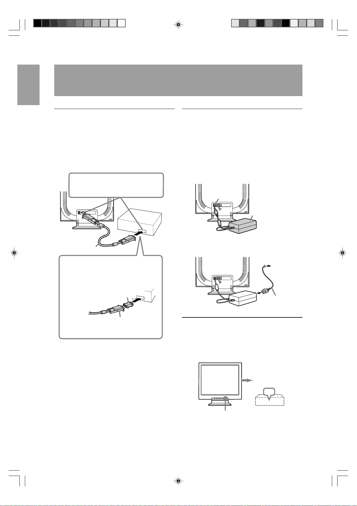
Connecting the monitor to a computer
(PC etc.)
When connecting, ensure that both the monitor and
computer are switched off.
Note:
- Do not overly bend the cable or add extension
cords as this could lead to malfunction.
Firmly insert the analog RGB ter minal
(mini D-sub 15 pin with 3 rows) then
tighten the screws each side.
RGB signal cable
If connecting to a D-sub 15 pin 2 row Apple
Power Macintosh, attach a Macintosh conversion adapter (to be purchased separately) to
the RGB signal cable.
Connecting the monitor to a power source
Before connecting, first turn off the monitor's main
power switch.
Note:
- Do not overly bend the cable or add extension
cords as this could lead to malfunction.
1. Connect the AC adapter to the monitor's power
terminal.
Power terminal
AC adapter
2. Attach the power cord to the AC adapter and
place the power plug into the AC terminal.
AC terminal
Macintosh conversion adapter
RGB signal cable
After connecting the adapter, tighten the
screws on each side to fix into place.
Power cord
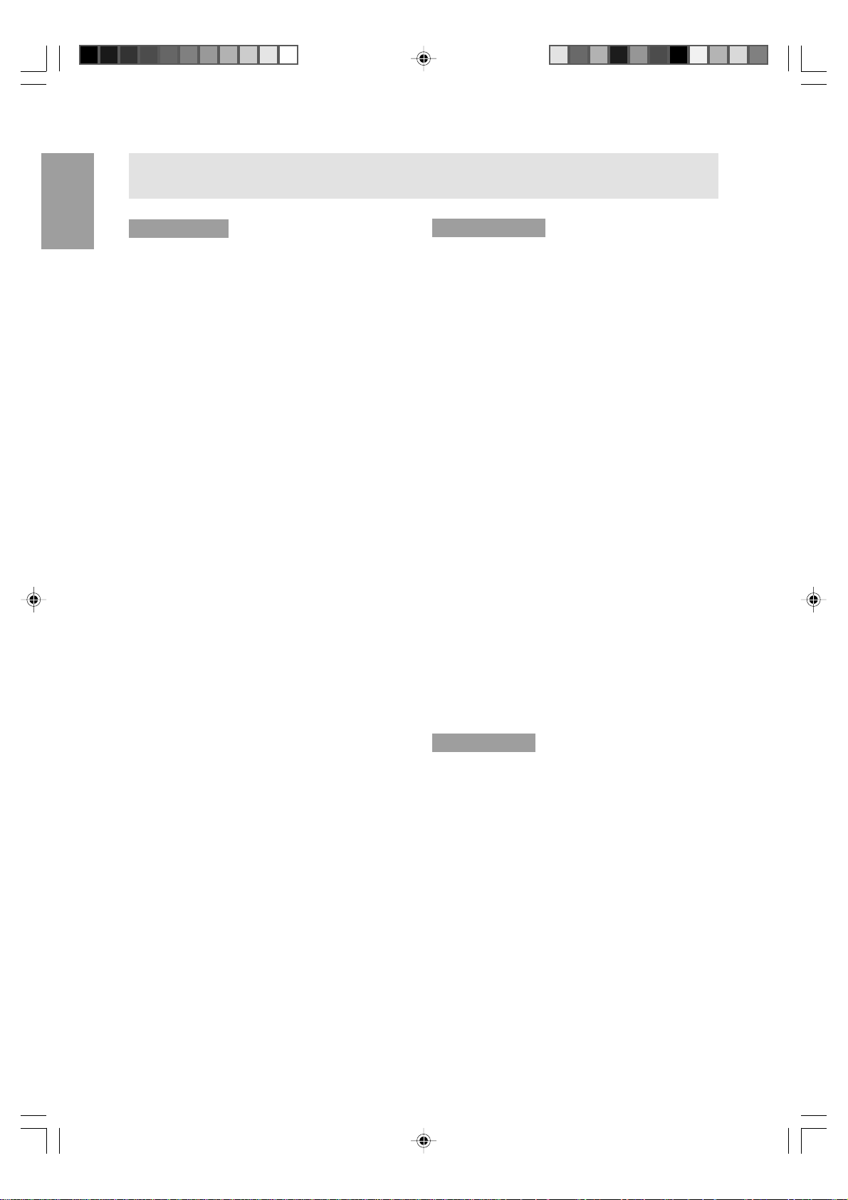
Turning the power on
1 . Press the monitor's power button.
2 . Turn on the computer.
The power LED will be lit green, and the screen
will display an image.
Turn on device to
which monitor is
connected
ON
Press power button
12

Connecting the monitor and turning the monitor on and off
Note:
- If using the monitor for the first time or after
having changed the system settings during use,
perform an automatic screen adjustment.
- Depending on the computer or OS, it may be
necessary to use the computer to install monitor
set-up information. If so, follow the steps below to
install the monitor set-up information.
Turning the power off
1 . Turn the computer off.
2 . Press the monitor's power button.
The Pow er LED will disappear.
If the monitor is not going to be used for a long
period of time, be sure to unplug it from the AC
outlet.
Turn off device
to which monitor
is connected
OFF
Press power button
Installing set-up information and the ICC
profile (for Windows)
Depending on the computer or OS, it may be necessary to use the computer to operate the installation
of monitor set-up information etc. If so , follow the
steps below to install the monitor set-up information.
(Depending on the type of computer or OS, command names and methods may differ. Please follow
the computer’s own oper ation manual while reading
this.)
About the ICC profile
An ICC (International Color Consortium) profile
is a file that describes the color characteristics of
the LCD monitor. By using an application that
works together with an ICC profile, a high color
resolution can be realized.
- Windows98, WindowsMe and Windows2000
all use the ICC profile.
- When installing Windows98, WindowsMe and
Windows2000 set-up information (described
below), the ICC profile is also installed. If y ou
would like to install the ICC program only,
please refer to Installing the ICC profile on
page 15.
- When using the ICC profile, please set the
[WHITE BALANCE] to [STD] .
English
Installing set-up information
For Windows95
Installing monitor set-up information into Windows95.
This explanation assumes that the floppy disk driv e
is "A drive".
1 . Place the Utility Disk (provided) into the compu-
ter's A drive.
2 . Click on the [Start] button. From [Settings],
choose [Control Panel].
3 . Double click on [Display].
4 . Click on [Settings], [Advanced Properties], and
[Monitor], then [Change].
5 . Click on [Have disk], confirm that [Copy manufac-
turer's files from:] is [A:] then click [OK].
6. Confirm that the monitor details are selected, and
click [OK].
7 . Check that the monitor details are display ed, then
click [Apply].
8 . Click [OK], and close the window.
9 . Remove the Utility Disk from the A driv e .
13
Connecting the monitor and turning the monitor on and off
For Windo ws98
Installing monitor set-up information into Windows98, and setting the monitor's ICC profile as a
predetermined value.
This explanation assumes that the floppy disk driv e
is "A drive".
If the "Add new Hardware Wizard" has appeared:
1 . Place the Utility Disk (provided) into the compu-
ter's A drive.
2 . Click [Next].
3. Check [Displa y a list of all the drivers in a specific
location, so you can select the driver you w ant.],
then click [Next].
4. When [Models] is display ed, clic k on [Have disk],
confirm that [Copy manufacturer's files from:] is
[A:], and click [OK].
5. Confirm that the monitor details are selected,
then click [Next], [Next], and [Finish]. If the "Add
New Hardware Wizard" appears , repeat the
installation commands beginning from 2 above.
6 . Remove the Utility Disk from the A drive .
If the "Add New Hardware Wizard" has not appeared:
1 . Place the Utility Disk in the computer's A drive.
2 . Click on the [Start] button. From [Settings],
choose [Control Panel].
3 . Double click on [Displa y].
4 . Click on [Settings], [Advanced] and [Monitor].
5 . In [Options], check [Automatically detect Plug &
Play monitors] and click on [Change].
6 . Click [Next].
7 . Click on [Display a list of all the drivers in a
specific location, so you can select the driver you
want.], then click [Next].
8 . When [Models] is displayed, clic k on [Have disk],
confirm that [Copy manufacturer's files from:] is
[A:], and click [OK].
9 . Confirm that the monitor details are selected,
then click [Next], [Ne xt], and [Finish].
10 .Check that the monitor details are displayed, then
click [Apply].
11 .Click [OK], and close the window .
12 .Remove the Utility Disk from the A drive.
For Windo ws2000
Installing monitor set-up information into Windows2000, and setting the monitor's ICC profile as a
predetermined value.
This explanation assumes that the floppy disk driv e
is "A drive".
1 . Place the Utility Disk (provided) into the compu-
ter's A drive.
2 . Click on the [Start] button. From [Settings],
choose [Control Panel].
3 . Double click on [Displa y].
4 . Click on [Settings], [Advanced] and [Monitor].
5 . Click on [Properties], [Driver] and [Update
Driver].
6 . When [Upgrade Device Driver Wizard] appears,
click [Next].
7 . Check [Displa y a list of the known drivers for this
device so that I can choose a specific driver] and
click [Next].
8 . When [Models] is displayed, clic k on [Have disk],
confirm that [Copy manufacturer's files from:] is
[A:], and click [OK].
9 . Select the monitor from the list displayed and
click [Next].
10 .Click [Next], confirm that the monitor's name
appears on the screen, and click [Finish]. If [The
Digital Signature Not Found] appears, click [Yes].
11 .Click on [Close].
12 .Click [OK], and close the window .
13 .Remove the Utility Disk from the A drive.
For WindowsMe
Installing monitor set-up information into
WindowsMe, and setting the monitor's ICC profile as
a predetermined value.
This explanation assumes that the floppy disk driv e
is "A drive".
If the "Add new Hardware Wizard" has appeared:
1 . Place the Utility Disk (provided) into the compu-
ter's A drive.
2 . Check [Specify the location of the driver [Ad-
vanced]] and click [Next].
3 . Check [Displa y a list of all the driv ers in a specific
location, so you can select the driver you w ant.],
then click [Next].
4 . When [Models] is displayed, clic k on [Have disk],
confirm that [Copy manufacturer's files from:] is
[A:], and click [OK].
14

Connecting the monitor and turning the monitor on and off
5 . Select the monitor details from the list, then click
[Next], [Next], and [Finish]. If the "Add new
Hardware Wizard" appears, repeat the installation commands beginning from 2 above.
6 . Remove the Utility Disk from the A drive .
If the "Add New Hardware Wizard" has not appeared:
1 . Place the Utility Disk in the computer's A drive.
2 . Click on the [Start] button. From [Settings],
choose [Control Panel].
3 . Double click on [Displa y].
4 . Click on [Settings], [Advanced] and [Monitor].
5 . In [Options], check [Automatically detect Plug &
Play monitors] and click on [Change].
6 . Check [Specify the location of the driver
[Advanced]] and click [Ne xt].
7 . Check [Display a list of all the drivers in a specific
location, so you can select the driver you w ant.]
and click [Next].
8 . When [Models] is displayed, clic k on [Have disk],
confirm that [Copy manufacturer's files from:] is
[A:], and click [OK].
9 . Select the monitor details, then click [Next],
[Next], and [Finish].
10 .Check that the monitor details are displayed, then
click [Apply].
11 .Click [OK], and close the window .
12 .Remove the Utility Disk from the A drive.
Installing the ICC profile
Installing the monitor’s ICC profile. (If the set-up
information has already been installed, so too has
the profile, and there is no need to install it.)
This explanation assumes that the floppy disk driv e
is "A drive".
1. Place the Utility Disk in the computer’ s A driv e.
2. Click on the [Start] button. From [Settings],
choose [Control Panel].
3. Double click on [Display].
4. Click on [Settings] and [Adv anced].
5. Click on [General] and from [Compatibility] select
[Apply the new display setting without restarting],
then click on [Color Management].
6. Click [Add], and select [3 ½ Flopp y [A:]] as the
file location.
7. Choose the color profile that you would lik e to
install, and click on [Add].
8. Choose the profile and click on [Set As Def ault].
9. Click [OK], and close the window.
10.Remove the Utility Disk from the A drive.
Information about the ColorSync profile
(for MacOS)
About the ColorSync profile
ColorSync is the Apple Corporation's color
management system and is a function that
enables color resolution to be realized when
used with a compatible application. A ColorSync
profile describes the color characteristics of the
LCD monitor.
Notes:
- This monitor's ColorSync profile works with
MacOS8.5 or above.
- When using the ColorSync profile, please set
the [WHITE BALANCE] to [STD] .
Setting up the ColorSync profile
Notes:
- A floppy disk drive is necessary. In addition, it is
necessary to have PC Exchange or File
Exchange installed in your system.
- Depending on the type of computer or OS,
command names and methods may differ. Please
follow the computer’s own operation manual while
reading this.
1. Place the Utility Disk (provided) into the
computer’s floppy disk drive.
2. Copy the profile to be used from the Mac folder
on the Utility Disk to the ColorSync profile folder
located within the system folder .
3. Using the ColorSync on the control panel,
choose the profile to be used.
English
- When using the ICC profile, please set the
[WHITE BALANCE] to [STD].
15

Adjusting the screen display
Adjustment the backlight (right column)
Brightness of backlight can be adjusted.
Automatic screen adjustment (p.17)
The CLOCK, PHASE, H-POS (horizontal positioning) and V-POS (vertical positioning) functions can
be adjusted automatically .
Manual screen adjustment (p. 18)
Fine adjustments can be made using the On Screen
Display (OSD) Menu.
Note:
- All adjustments will be saved even after turning
the power off.
Resetting all adjustment values
All adjustment values can be returned to their
original ex-factory values in one command.
1 . Turn off the monitor power.
2 . Press the MENU button and the SELECT button
simultaneously, and while doing this press the
power button (i.e. turn the power on). When [ALL
RESET] appears on the screen, the reset is
complete.
3. Turn off the monitor power.
Note:
- While ALL RESET is displayed, the control
buttons are disabled.
- It is not possible to reset values when the
adjustment lock is in place. Remove the
adjustment lock before attempting to operate
control buttons.
Adjustment lock function
By disabling the control buttons (i.e. setting the lock)
any attempted changes to adjusted values will be
voided.
1 . Turn off the monitor power.
2. While pressing the MENU button, press the
power button (i.e. turn the power on).
Continue to press the button until the message
appears on the screen.
When the menu is unlocked:
[ADJUSTMENT LOCKED] will appear on
the screen, and the lock will be set.
When the menu is locked:
[ADJUSTMENT UNLOCKED] will appear
on the screen, and the lock will be
removed.
Note:
- When the lock is in place, all b uttons other than
the power button are disab led.
Adjusting the backlight
1 . Without the OSD Menu being displayed, press
button or the button.
the
BRIGHT 31
2 . Adjust by pressing the
button (lighter).
The BRIGHT bar automatically disappears
several seconds after the last command.
button (darker) or the
ADJUSTMENT menu reset
The adjustment values of the analogue signal time’ s
ADJUSTMENT menu can be returned to their
original ex-factory values.
1 . Turn on the monitor power.
2 . Press the MENU button and the
simultaneously. When [RESET] appears on the
screen, the reset is complete.
button
16

Adjusting the screen display
Automatic screen adjustment
Options in the ADJUSTMENT Menu can be adjusted
automatically (CLOCK, PHASE, H-POS V-POS).
Note:
- When setting up this monitor for the first time or
after having changed an aspect of the current
system, perform an automatic screen adjustment
before use.
Automatic adjustment screen display
To perform an automatic adjustment, first display an
image that makes the entire screen very bright. If
you are using Windows, you can also use the
Adjustment Pattern on the accompanying Utility Disk
for Windows.
Displaying the Adjustment Pattern (f or Windows)
This explanation is for Windo ws 95/98/2000/Me, and
assumes that the floppy disk drive is [A drive].
Note:
- If the floppy disk drive of your computer is not
"A drive", please read the below substituting the
floppy disk drive you are using in place of
"A drive" or "A".
1 . Place the Utility Disk (provided) into the
computer's A drive.
2 . Open [My Computer] and select [3 ½ Floppy
(A:)]. If using Windows 3.1, open [File Manager]
and choose "A drive".
3 . Double click on [Adj_uty.exe] to run the
Adjustment Program. The Adjustment Pattern will
appear.
Adjustment pattern
Adjusting the screen automatically
1 . Press the MENU button.
The ADJUSTMENT Menu will be displayed.
ADJ USTMENT
MANUAL AUTO
CLOCK
PHASE 16
H
-
POS 200
-
POS 29
V
1024X768
V: 75Hz H: 60.0kHz
127
2 . Press the button.
The screen will become dark and [ADJUSTING]
will be displayed. After a few seconds the
ADJUSTMENT Menu will return. (The automatic
adjustment is now complete.)
3 . Press the MENU button 4 times to make the On
Screen Display (OSD) Menu disappear.
Notes:
- In most cases automatic adjustment is sufficient.
- If necessary due to any of the following, manual
adjustments (p. 18) can be performed after the
automatic adjustment.
- When further fine adjustment is needed.
- When the computer’s video input signals are
Composite Sync or Sync On Green.
(Automatic adjustments may not be possib le .)
- When [OUT OF ADJUST] is displayed.
(When the screen displays an entirely dark
image, the automatic screen adjustment may
be disabled. When making an automatic
adjustment, be sure to either use the
Adjustment Pattern or try displaying an image
that makes the entire screen very bright.)
English
Notes:
- After completing the adjustment, press the
computer's [Esc] key to e xit the Adjustment
Program.
- If your computer's display mode is set to 65K
colors, you may see the different color levels in
each color pattern or the gray scale may look
colored. (This is due to the input signal
specification and is not a malfunction.)
17

Adjusting the screen display
Manual screen adjustment
Adjustments can be made using On Screen Display
(OSD) Menu provided.
1. Display an image that mak es the entire screen
very bright. If using Windows, you can open and
use the Adjustment Pattern on the accompanying
Utility Disk. (p. 17)
2.Press the MENU button.
The ADJUSTMENT Menu will be displayed.
ADJ USTMENT
MANUAL AUTO
CLOCK
PHASE 16
H
-
POS 200
-
POS 29
V
1024X768
V: 75Hz H: 60.0kHz
At this point relevant menu options can be
adjusted.
Each time the MENU button is pressed the next
menu is selected. (ADJUSTMENT → GAIN
CONTROL → WHITE BALANCE → MODE
SELECT → OSD Menu disappears)
Notes:
- The OSD Menu automatically disappears
approximately 30 seconds after the last
command.
- This explanation is based on using the
Adjustment Pattern (for Windo ws) to mak e
adjustments.
127
ADJUSTMENT Menu
ADJ USTMENT
MANUAL AUTO
CLOCK
PHASE 16
H
-
POS 200
-
POS 29
V
1024X768
V: 75Hz H: 60.0kHz
127
MANUAL:Individual menu options are manually
adjusted.
A UTO: Every menu option is automatically
adjusted.
Notes:
- Press the
button to select [A U TO].
- To choose a menu option: SELECT button
- To go to the next menu: MENU button
CLOCK
The figure below demonstrates how to adjust so that
vertical flicker noise is not emitted. (
Ver tical flicker noise
buttons)
PHASE
The figure below demonstrates how to adjust so that
horizontal flicker noise is not emitted. (
buttons)
Note:
- Adjustments to PHASE should be made only
after CLOCK has been correctly set.
Horizontal flicker noise
H-POS (horizontal positioning) and V-POS
(vertical positioning)
To center the screen image within the boundaries of
the screen, adjust the left-right (H-POS) values and
the up-down (V-POS) values. (
buttons)
Screen frame
18

Adjusting the screen display
GAIN CONTROL Menu
GAIN CONTROL
MANUAL AUTO
BL ACK
CONTRAST 80
1024X768
V: 75Hz H: 60.0kHz
LEVEL 16
MANUAL:Individual menu options are manually
adjusted.
A UTO: Every menu option is automatically
adjusted using the Auto Gain Control*
function,
Notes:
- Press the
button to select [A U TO].
- To choose a menu option: SELECT button
- To go to the next menu: MENU button
* Auto Gain Control function
- The Auto Gain Control adjusts contrast and b lac k
level based on the brightest color of the image
displayed. If you are not using the Adjustment
Pattern it is necessary to have an area of 5 mm x
5 mm of white displayed, and if not adjustments
may not be possible. (In such case, [OUT OF
ADJUST] will appear and setting values remain
unchanged.)
- If the signal coming from the computer is
composite sync or sync on green, automatic
adjustment cannot be performed. Please perform
manual adjustment instead.
BLACK LEVEL
Total screen brightness can be adjusted while
watching the color pattern. (
buttons)
WHITE BALANCE Menu
WHITE BALANCE
STD WARM USER
COOL
-
CONTRAST
R
-
CONTRAST
G
-
CONTRAST
B
1024X768
V: 75Hz H: 60.0kHz
Notes:
- On settings other than [STD] not all graduations
can be displayed. To display all graduations, set
to [STD].
- Use the
buttons to select [COOL], [·], [STD],
[·], [WARM] or [USER].
- Selecting USER will display the setting v alues for
[R-CONTRAST], [G-CONTRAST] and [BCONTRAST], in order to make fine adjustments.
- Use the SELECT button to select
[R-CONTRAST], [G-CONTRAST] and
[B-CONTRAST].
- To go to the next menu: MENU button
COOL . . . Color tone bluer than standard
• . . . . . . Color tone slightly bluer than standard
STD . . . . . Color tone standard setting
• . . . . . . Color tone slightly redder than standard
WAR M. . . Color tone redder than standard
USER
R-CONTRAST. . .
button for b lue-g reen
button for red
G-CONTRAST . .
button for purple
button for g reen
B-CONTRAST. . .
button for yellow
button for blue
English
Color pattern
CONTRAST
While watching the color pattern, adjustments can be
made so that all graduations appear. (
buttons)
19

Adjusting the screen display
MODE SELECT Menu
MODE SELECT
OS D
H-
POSITION
V-
OS D
400
SCAL I NG 3
LANGUAGE
1024X768
V: 75Hz H: 60.0kHz
POSITION
L I NES 640 720
Notes:
- Depending on the resolution of the input signal,
even if menu options can be selected, the display
may not change.
- To choose a menu option: SELECT button
- When adjustment complete: MENU button
OSD H-POSITION (OSD horizontal position)
The position of the OSD display can be moved to the
left and right. (
buttons)
OSD V-POSITION (OSD vertical position)
The position of the OSD display can be moved up
and down. (
buttons)
400 LINES (degree of resolution)
You can specify the horizontal resolution of a 400line screen when using US text, etc.
buttons)
(
640: 640 X 400 dot mode
720: 720 X 400 dot mode (US text etc.)
LANGUAGE
Messages displayed on the screen and OSD Menu
contents can be changed to the following languages.
Dutch, English, French, German, Spanish, Italian,
Swedish.
1 . Press the
button.
The Language Selection Menu will be displayed
on the screen.
2 . Use the SELECT button to choose a language.
3 . Press the MENU button or the
button.
The setting is complete.
Note:
- As the resolution input for other than 400 lines is
done automatically, there is no need to set it.
SCALING (Level of scaling)
The sharpness of the image can be adjusted. (
buttons)
Note:
- When the display mode is set to less than
1024 x 768 pixels, the display is enlarged to
cover the whole screen (i.e. the side ratio of the
display may change).
- If a resolution of 1024 x 768 pixels cannot be
achieved even after expansion is attempted, the
screen's perimeter will display black. (This is not
a malfunction.)
20

Monitor care and repair
Monitor care
Always remove the plug from the AC outlet when
cleaning the monitor.
Cabinet and control panel section
Use a soft dry cloth to lightly wipe away any grime
from the cabinet and control panel.
If they are very dirty , apply neutral detergent to a
dampened soft cloth, wring it out well and wipe away
grime.
LCD panel section
Use a soft dry cloth to lightly wipe away dirt and dust
from the surface of the LCD panel. (A soft cloth such
as gauze or that used for lens cleaning is suitab le.)
CAUTION!
- Nev er use thinner, benzine, alcohol, glass
cleaner, etc , as this could lead to color change or
change in shape.
- Nev er scratch the monitor with an ything hard or
apply strong pressure as this could leave marks
or result in malfunction.
Storage
If the monitor will not be used for a long period of
time, be sure to remove the pow er plug from the AC
outlet.
CAUTION!
- Do not leave the monitor in contact with rubber or
plastic items for long periods of time as this could
lead to color change or change in shape.
Troubleshooting
If you think the monitor may be faulty, please check
the following points before taking it to be repaired.
If afterwards it still does not work, please contact the
shop where you purchased the monitor or your
nearest Sharp authorized Service Center.
The monitor's florescent tubes have a limited lif e
span.
- If the screen darkens, persistently flickers or
does not light up, it ma y be necessary to
replace the florescent tube unit. Please
inquire at the shop where you purchased the
monitor or your nearest Sharp authorized
Service Center. (Never attempt this
replacement on your own.)
- In the initial period of use, due to the
characteristics of florescent tubes the screen
may flick er. (This is not a malfunction.)
Should this happen, check by first turning off
the power , then turning it on again.
No image appears on the monitor (Po wer LED is not
lit)
- Are the AC adapter and the pow er cord
connected properly? (p. 12)
No image appears on the monitor (Po wer LED is lit)
- Is the computer connected properly? (p. 12)
- Is the computer turned on?
- Does the computer's signal timing correspond to
monitor specifications? (p. 23)
- Is the computer in power-saving mode?
Control buttons do not work
- Is the adjustment lock on? (p . 16)
English
The image appears distorted
- Does the computer's signal timing correspond to
monitor specifications? (p. 23)
- P erf orm automatic adjustment. (p . 17)
21

Specifications
Product specifications Dimensions (Units: mm)
LCD display
38 cm measured diagonally
TFT LCD module
Resolution (max.)
XGA 1024 x 768 pixels
Displayab le colors (max.)
16.77 million colors (8 bit)
Brightness (max.)
260cd/m
Dot pitch
0.297(H) 0.297(V) mm
Contrast ratio
400:1
Angle of visibility
Left-right 160°; Up-down 150°
Screen display size
Horizontal 304.1 mm x Vertical 228.1 mm
Video signal
Analog RGB (0.7Vp-p) [75Ω]
Sync signal
Separate Sync (TTL level: +/-), Sync on
Green, Composite Sync (TTL level: +/-)
Expansion compensation
Digital screening (enlargement of display to
correct VGA/SV GA)
Plug & Play
VESA: DDC1/DDC2B compatib le
Pow er management
VESA: based on DPMS
Input signal terminal
15 pin mini D-sub (3 rows)
Screen tilt
Upward 0° - 25°; downw ard 0° - 5°
Pow er supply
AC100-240V, 50/60Hz (Use special AC adapter,
type NL-A60J of Sharp Corporation.)
Temperature of operating environment
5 - 35°C
Pow er consumption
Maximum 29W (3W when in power-saving mode)
(Use special AC adapter .)
Dimensions (W x D x H)
339 mm x 187 mm x 322 mm
Weight
Approx. 3.4 kg
(Excluding AC adapter and RGB signal cable.)
2
339
283
322
187
47
187
RGB signal cable: Appro x.1.8m
Special AC adapter:
Approx.1.5m
Approx. H 124mm x D 62 mm x H 36mm
22

Specifications
Signal timings
Display mode Hsync (kHz) Vsync (Hz)
31.5kHz 60Hz 25.175MHz
640x480 37.9kHz 72Hz 31.5MHz
37.5kHz 75Hz 31.5MHz
VESA 35.1kHz 56Hz 36.0MHz
800x600
37.9kHz 60Hz 40.0MHz
48.1kHz 72Hz 50.0MHz
46.9kHz 75Hz 49.5MHz
48.4kHz 60Hz 65.0MHz
1024x768 56.5kHz 70Hz 75.0MHz
60.0kHz 75Hz 78.75MHz
US text 720x400 31.5kHz 70Hz 28.3MHz
Power Macintosh 640x480 35.0kHz 66.7Hz 30.2MHz
series 832x624 49.7kHz 74.6Hz 57.3MHz
1024x768 60.2kHz 75Hz 80.0MHz
Dot frequency
(MHz)
Notes:
- All are compliant only with non-interlaced.
- Frequencies for Power Macintosh are reference values.
- If the monitor is receiving timing signals that are not compatible, [OUT OF TIMING] will appear. Follow
your computer's instruction manual to set the timing to be compatible with the monitor.
- If the monitor is not receiving any signal (synch signal), [NO SIGNAL] will appear .
English
The connector pin
Mini D-sub connector with 15 pins
5
10
15 11121314
1234
6789
Number Function
1 Red video signal input
2 Green video signal input
3 Blue video signal input
4 GND
5 GND
6 For red video signal GND
7 For green video signal GND
8 For blue video signal GND
9+ 5V
10 GND
11 N.C.
12 DDC data
13 For H-sync signal input
14 For V-sync signal input
15 DDC clock
23

Specifications
Power management
The monitor is based on VESA DPMS (Displa y
Pow er Management Signaling).
To activate the monitor's Power Management function, both the video card and the computer must
conform to the VESA DPMS standard.
DPMS mode Screen Power H-sync V-sync
consumption
ON Display on 29W Yes Ye s
STANDBY No Yes
SUSPEND Display off 3W Yes No
OFF No No
DDC (Plug & Play)
This monitor supports the VESA DDC (Display Data
Channel) standard.
DDC is a signal standard for carrying out Plug &
Play functions on the monitor or PC. It transfers
information such as degree of resolution between
the monitor and PC. You can use this function if your
PC is DDC compliant and if it is set so that it can
detect the Plug & Play monitor .
There are many varieties of DDC due to the differences between systems. This monitor works with
DDC1 and DDC2B.
24

Instructions for attaching a VESA compliant arm
An arm based on the VESA standard can be attached to the monitor. The arm must be purchased
separately.
When choosing the arm to be installed please take
note of the following points.
- The arm should be compatible with the VESA
standard, and there must be a gap of 75mm x
75mm between the screw holes on the section to
be attached.
- The arm must not fall off or break off after being
attached to the monitor.
1 . Ensure that both the monitor and computer are
switched off.
2. Remove the AC adapter and the RGB signal
cable.
3 . Press down on the stand and gently fold bac k the
monitor.
5 . Attach the arm to the monitor with four screws.
Information
The screws used to
attach the arm should be
M4 screws with a length
of 4 mm ~ 6 mm protruding from the surface to be
attached. Using any other
kind of screw may lead to
the monitor falling off or
damage to the internal
part of the monitor.
4 ~ 6 mm
Screw used to
attach arm
Arm
Part of monitor to
which arm is
attached
6 . Connect the AC adapter and the RGB signal
cable.
English
4 . Being careful not to damage the monitor, spread
out a soft cloth and lay the monitor on it displayside down.
25

26

Inhaltsverzeichnis
Hinweis für Benutzer in den USA . . . . . . . . . . . . . . . . . . . . . . . . . . . . . . . . . . . . . . . . . . . . . . . . . . . . . . 28
TCO'99. . . . . . . . . . . . . . . . . . . . . . . . . . . . . . . . . . . . . . . . . . . . . . . . . . . . . . . . . . . . . . . . . . . . . . . . . . 29
Hinweis für Benutzer in Europa . . . . . . . . . . . . . . . . . . . . . . . . . . . . . . . . . . . . . . . . . . . . . . . . . . . . . . . 31
Hinweis für Benutzer in GB . . . . . . . . . . . . . . . . . . . . . . . . . . . . . . . . . . . . . . . . . . . . . . . . . . . . . . . . . . 32
Hinweis für Benutzer in Australien . . . . . . . . . . . . . . . . . . . . . . . . . . . . . . . . . . . . . . . . . . . . . . . . . . . . . 32
Tips und Sicherheitsvorkehrungen . . . . . . . . . . . . . . . . . . . . . . . . . . . . . . . . . . . . . . . . . . . . . . . . . . . . . 33
Produktbeschreibung . . . . . . . . . . . . . . . . . . . . . . . . . . . . . . . . . . . . . . . . . . . . . . . . . . . . . . . . . . . . . . . 34
Anschließen des Monitors und Ein- und Ausschalten des Monitors. . . . . . . . . . . . . . . . . . . . . . . . . . . . 36
Verbinden des Monitors mit einem Computer (PC usw.) . . . . . . . . . . . . . . . . . . . . . . . . . . . . . . . . . 36
Anschließen des Monitors an eine Stromquelle . . . . . . . . . . . . . . . . . . . . . . . . . . . . . . . . . . . . . . . 36
Einschalten des Monitors . . . . . . . . . . . . . . . . . . . . . . . . . . . . . . . . . . . . . . . . . . . . . . . . . . . . . . . . 36
Ausschalten des Monitors . . . . . . . . . . . . . . . . . . . . . . . . . . . . . . . . . . . . . . . . . . . . . . . . . . . . . . . . 37
Installieren der Setup-Informationen und des ICC-Profils (für Windows) . . . . . . . . . . . . . . . . . . . . 37
Informationen zum Profil ColorSync (für MacOS) . . . . . . . . . . . . . . . . . . . . . . . . . . . . . . . . . . . . . 39
Einstellen der Bildschirmanzeige . . . . . . . . . . . . . . . . . . . . . . . . . . . . . . . . . . . . . . . . . . . . . . . . . . . . . . 40
Einstellen der Hintergrundbeleuchtung . . . . . . . . . . . . . . . . . . . . . . . . . . . . . . . . . . . . . . . . . . . . . . 40
Automatische Bildschirmeinstellung . . . . . . . . . . . . . . . . . . . . . . . . . . . . . . . . . . . . . . . . . . . . . . . . 41
Manuelle Bildschirmeinstellung. . . . . . . . . . . . . . . . . . . . . . . . . . . . . . . . . . . . . . . . . . . . . . . . . . . . 42
Pflege des Monitors und Reparaturen . . . . . . . . . . . . . . . . . . . . . . . . . . . . . . . . . . . . . . . . . . . . . . . . . . 45
Pflege des Monitors . . . . . . . . . . . . . . . . . . . . . . . . . . . . . . . . . . . . . . . . . . . . . . . . . . . . . . . . . . . . 45
Lagerung . . . . . . . . . . . . . . . . . . . . . . . . . . . . . . . . . . . . . . . . . . . . . . . . . . . . . . . . . . . . . . . . . . . . . 45
Fehlersuche . . . . . . . . . . . . . . . . . . . . . . . . . . . . . . . . . . . . . . . . . . . . . . . . . . . . . . . . . . . . . . . . . . 45
Technische Daten. . . . . . . . . . . . . . . . . . . . . . . . . . . . . . . . . . . . . . . . . . . . . . . . . . . . . . . . . . . . . . . . . . 46
Anweisungen zum Anbringen eines VESA-kompatiblen Monitorarms . . . . . . . . . . . . . . . . . . . . . . . . . . 49
GBFIE
Deutsch
27

Hinweis für Benutzer in den USA
FCC-Hinweis
ACHTUNG – Änderungen oder Modifikationen an diesem Gerät, die nicht ausdrücklich vom Hersteller
genehmigt wurden, können laut FCC-Richtlinie zum Erlöschen der Betriebsberechtigung führen.
Hinweis: Dieses Gerät wurde geprüft und entspricht den Grenzwerten für digitale Geräte der Klasse B
gemäß Teil 15 der FCC-Richtlinien.
Diese Grenzwerte dienen dem ausreichenden Schutz gegen Störungen bei einer Installation in
Wohnbereichen. Dieses Gerät erz eugt Funkfrequenzenergie , arbeitet damit und kann diese abstrahlen.
Falls bei der Installation die Anweisungen in der Anleitung k eine Beachtung finden, k önnen
schwerwiegende Störungen beim Funkverkehr hervorgerufen werden. Es kann jedoch k eine Gar antie
gegeben werden, daß in bestimmten Installationen nicht doch Störungen auftreten. Sollte das Gerät
Störungen beim Radio- oder Fernsehempfang hervorrufen, die durch Ein- und Ausschalten des Gerätes
festgestellt werden können, sollte der Anw ender v ersuchen, die Störung durch eine der f olgenden
Maßnahmen zu beheben.
- Die Empfangsantenne neu ausrichten oder deren Standort ändern.
- Den Abstand zwischen dem Gerät und dem Empfänger vergrößern.
- Das Gerät an eine andere Steckdose anschließen, die nicht zum Stromkreis des Empfängers gehört.
- Den Händler oder einen erfahrenen Rundfunk-/Fernsehtechniker zu Rate ziehen.
Nur die mitgelieferten Kabel und das Netzkabel verwenden, um eine Einhaltung der FCC-Richtlinien für
Computer-Geräte der Klasse B sicherzustellen.
Konf ormitätserklärung
SHARP LCD-Farbmonitor LL-T15V1
Dieses Gerät entspricht Teil 15 der FCC-Richtlinien. Um dieses Gerät in Betrieb nehmen zu dürfen,
müssen folgende Bedingungen eingehalten werden: (1) Dieses Gerät darf keine Störungen hervorrufen,
und (2) dieses Gerät darf nicht anfällig für Störungen sein, darunter Störungen, die zu einer Verkleinerung
des Anzeigeformats führen können.
V erantwortlicher Hersteller: SHARP ELECTRONICS CORPORA TION
Sharp Plaza, Mahwah, New Jersey 07430
TEL :1-800-BE-SHARP
* Als ENERGY STAR-Partner bestätigt SHARP, daß dieses Produkt die Richtlinien des ENERGY STAR
für sparsamen Verbrauch einhält.
In diesem Produkt wird bleihaltiger Lötzinn und eine Leuchtstofflampe mit einem geringen
Quecksilberanteil verwendet. Die Entsorgung dieser Materialien unterliegt möglicherweise bestimmten
Umweltrichtlinien. Inf ormationen zur Entsorgung bzw. zum Recycling können von den örtlichen Behörden
oder von der Electronics Industries Alliance unter www.eiae .org angefordert werden
28

Herzlichen Glückwunsch!
Sie haben gerade ein Gerät mit TCO‘99-Zulassung und entsprechender Kennzeichnung erworben! Damit
haben Sie sich für ein Produkt entschieden, das für professionelle Anwendungen konzipiert ist. Mit Ihrem
Kauf leisten Sie auch einen Beitrag zum Umweltschutz und zur W eiterentwic klung v on umw eltfreundlichen
Elektronikprodukten.
Warum verkaufen wir Computer mit Umweltkennzeichnung?
In vielen Ländern dient die Kennzeichnung mit Umweltzeichen als Anreiz für die F ertigung und Bereitstellung
umweltverträglicher Konsumgüter und Dienste. Das Hauptproblem im Zusammenhang mit Computern und
anderen elektronischen Geräten besteht darin, daß umweltschädliche Stoffe in den Produkten enthalten sind
und auch während der Fertigung eingesetzt werden. Da es bis jetzt noch nicht möglich ist, den Großteil der
elektronischen Geräte hinlänglich zu recyceln, gelangen fast alle dieser möglicherweise schädigenden
Substanzen früher oder später in den Naturkreislauf.
Weitere Eigenschaften eines Computers, beispiels weise sein Energie verbrauch, sind aus Sicht der Arbeitsumgebung (intern) und natürlichen Umgebung (extern) ebenfalls v on Bedeutung. Da alle Verfahren zur
Stromerzeugung negative Auswirkungen auf die Umwelt haben (beispielsweise saurer Regen, klimabeeinflussende Emissionen, radioaktiver Abfall), k ommt es darauf an, möglichst Energie zu sparen. Elektronische Geräte in Büros sind oft durchgehend eingeschaltet und verbrauchen deshalb viel Strom.
GBFIE
Deutsch
Welche Bedeutung hat die Kennzeichn ung?
Dieses Produkt entspricht den Anforderungen der TCO‘99-Verordnung, die sich mit internationalen Kennzeichnungen und Umweltzeichen für PCs bef aßt. Die Kennzeichnungen wurden gemeinsam v on der TCO
(Schwedische Zentralorganisation für Angestellte und Beamte), Svenska Naturskyddsf oreningen (Schwedische Gesellschaft für Naturschutz) und Statens Energimyndighet (Schwedische Nationale Energiebehörde)
entwickelt.
Zulassungsanforderungen beschäftigen sich mit den unterschiedlichsten Belangen: Umw elt, Ergonomie,
Nutzbarkeit, Emission elektrischer und magnetischer Felder , Energie v erbrauch und elektrische Sicherheit
sowie Brandschutz.
Die Umweltanforderungen beschränken u.a. das V orkommen und die V erwendung v on Schwermetallen,
brom- und chlorhaltigen Flammschutzmitteln, FCKW (Freon) und Chlorlösungsmitteln. Das Produkt muß
recyclingfähig sein, und der Hersteller muß einen Umweltplan ausgearbeitet haben, der in allen Ländern, in
denen das Unternehmen seine Betriebsstrategie realisiert, eingehalten werden muß.
Die Energieanforderungen beinhalten die Forderung, daß der Computer und/oder sein Anzeigegerät nach
einer bestimmten Zeit der Inaktivität die Leistungsaufnahme in einer oder mehreren Stufen verringern muß.
Die Reaktivierungszeit des Computers muß für den Benutzer in einem vernünftigen Rahmen liegen.
Gekennzeichnete Produkte müssen strenge Umweltanf orderungen einhalten, beispielsw eise hinsichtlich der
V erringerung elektrischer und magnetischer Felder , physikalischer und visueller Ergonomie und guter
Nutzbarkeit.
Nachfolgend finden Sie eine kurze Zusammenf assung der Umweltanf orderungen, die v on diesem Produkt
eingehalten werden. Ein Dokument mit allen Umweltkriterien können Sie unter f olgender Adresse anf ordern:
29

TCO Development
SE-114 94 Stockholm, Sweden
Fax: +46 8 782 92 07
Email (Internet): dev elopment@tco.se
Aktuelle Informationen zu Produkten mit TCO‘99-Zulassung und -K ennz eichnung erhalten Sie auch im
Internet unter folgender Adresse: http://www.tco-info .com/
Umweltanforderungen
Flammschutzmittel
Flammschutzmittel kommen in Platinen, Kabeln, Drähten, Verkleidungen und Gehäusen vor . Sie sollen die
Ausbreitung eines Brandes verhindern oder zumindest verz ögern. Bis zu 30 % der Kunststoffteile in einem
Computergehäuse können aus Flammschutzsubstanzen bestehen. Die meisten Flammschutzmittel enthalten Brom oder Chlorid und lassen sich in chemischer Hinsicht mit einer anderen Gruppe umweltschädigender Stoffe, den PCBs, in V erbindung bringen. Brom- und chlorhaltige Flammschutzmittel und die
PCBs stehen im Verdacht, schwere gesundheitliche Störungen hervorzurufen, darunter aufgrund des
bioakkumulativen* Prozesses reproduktiv e Schädigungen v on fischfressenden Vögeln und Säugetieren.
Flammschutzmittel wurden bereits im menschlichen Blut nachgewiesen. F orscher fürchten, daß es zu einer
Schädigung der Fötusentwicklung k ommen kann.
Die relevanten Anf orderungen der TCO’99 verlangen, daß Kunststoffbauteile mit einem Gewicht v on über
25 g keine Flammschutzmittel mit organisch gebundenem Brom oder Chlor enthalten dürf en.
Flammschutzmittel bei Platinen sind zulässig, da keine alternativen Lösungen zur Verfügung stehen.
Cadmium**
Cadmium kommt in Akkus und in den farberzeugenden Schichten bestimmter Computerbildschirme vor.
Cadmium schädigt das Nervensystem und ist in hoher Dosierung giftig. Die relevante TCO’99-Anforderung
verlangt, daß Batterien, die farberzeugenden Schichten von Anz eigebildschirmen und elektrische oder
elektronische Komponenten kein Cadmium enthalten dürf en.
Quecksilber**
Quecksilber kommt manchmal in Batterien, Relais und Schaltern vor . Es schädigt das Nervensystem und ist
in hoher Dosierung giftig. Die rele v ante TCO‘99-Anforderung verlangt, daß Batterien kein Quecksilber
enthalten dürfen. Außerdem verlangt sie, daß Quecksilber weder in elektrischen noch elektronischen Komponenten vorkommen darf, die zu gek ennz eichneten Einheiten gehören. Dabei gibt es jedoch eine Ausnahme. Im A ugenb lic k ist der Einsatz von Quecksilber in der Hintergrundbeleuchtung von Flachbildschirmen
zulässig, da es derzeit noch keine wirtschaftliche Alternative gibt. Die TCO bemüht sich um eine Abschaffung dieser Ausnahme, sobald eine quecksilberfreie Alternative zur V erfügung steht.
FCKW (Freon)
Die relevante TCO‘99-Anforderung verlangt, daß weder FCKW noch HFCKW während der F ertigung und
beim Zusammenbau des Produkts verwendet werden darf. FCKW (Freon) wird manchmal zum Waschen von
Platinen eingesetzt. FCKW z erstört Ozon und schädigt dadurch die Ozonschicht in der Stratosphäre. Die
Folge sind höhere ultraviolette Str ahlenbelastungen auf der Erde, w as beispiels w eise das Hautkrebsrisiko
(Malignes Melanom) erhöht.
Blei**
Blei findet man in Bildröhren, Anzeigebildschirmen, Lötverbindungen und Kondensatoren. Blei schädigt das
Nervensystem und führt in höherer Dosierung zu einer Bleivergiftung. Die relev ante TCO‘99-Anforderung
gestattet die Verwendung von Blei, da noch keine Ersatzstoffe entwick elt wurden.
*
Bioakkumulativ definiert man als Substanzen, die sich in lebenden Organismen ansammeln.
**
Blei, Cadmium und Quecksilber sind bioakkumulative Schw ermetalle.
30
 Loading...