

Page 1
SERVICE MANUAL
LCD COLOR MONITOR
MODEL LL-T155A
CONTENTS
NOTES TO SERVICE PERSONNEL................................................................................. 1
CAUTIONS IN SERVICING............................................................................................... 1
CHAPTER 1: OUTLINE OF THE PRODUCT AND NOMENCLATURE................................. 4
CHAPTER 2: REPLACING LAMPS....................................................................................... 6
CHAPTER 3: CONNECTION, ADJUSTMENT, OPERATION, AND FUNCTIONS................ 8
CHAPTER 4: TROUBLESHOOTING....................................................................................12
CHAPTER 5: TRIMING AND PROCESSING LEAD WIRES................................................14
CHAPTER 6: BLOCK DIAGRAM/UNIT TERMINALS ...........................................................15
CHAPTER 7: APPAEARANCE AND DISASSEMBLY DRAWINGS OF MECHANISMS......17
CHAPTER 8: PACKAGING METHOD..................................................................................18
Parts marked with " " is important for maintaining the safety of the set. Be sure to replace these parts with specified
ones for maintaining the safety and performance of the set.
This document has been published to be used
SHARP CORPORATION
for after sales service only.
The contents are subject to change without notice.
Page 2
■Notes to service personnel
·Pictorials
· This servic e manual and th e product us e a variety of pic torials in or der to assure the s afety of repair op erations and of the product
repaired.
· If those pictorials are ignored in repairing, the following troub les might occur:
· Understand the meaning of those pictorials and read this manual carefully before trying to repair the product.
DANDER:
WARNING:
CAUTION:
Failure to follow the instructions in the message might cause a serious accident or death.
Failure to follow the instructions in the message might cause a serious accident or death.
Failure to follow the instructions in the message may cause personal injury or damage to the asset.
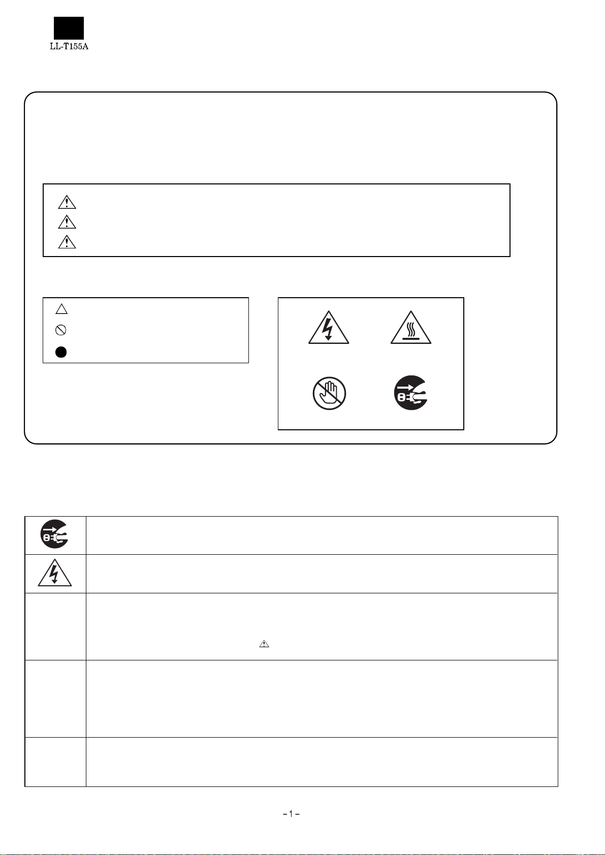
·Meaning of symbols ·Pictorial example
symbols mean the necessi t y of using caution.
symbols mean actions wh ich are prohibited.
symbols mean actions to b e required.
■Cautions in servicing
Locations which requi r e a special caution carry safety instructions using labels and stamps on the cabinet, chassis and components.
When servicing, observe t he instructions on such labels and stamps.
Electrical shock Hot surface
Don’t touch Remove power plug
Electrical shock and burn
1. Prior to servicing, make sure to remove the powe r supply plug.
Electrical shock
2. Some parts inside the unit have a high voltage. Use caution to avoid an electrical shock accident when servicing an energized
unit.
Use specified parts
3. The component pa rts of this unit have saf et y characteristics such as flam e resistance and dielectric st rength.
· Use replacement parts which have the same characteristics as those of the components parts used for this unit.
· In particular, component parts marked with in the circuit drawing parts list are important for mainta ining the safety of the
product. Make sure to use specified replacement parts.
Reinstall component parts in their original locations and return wires which have been rerouted for servicing
purposes to their original positions.
4. Some com ponent par ts us e ins ulati ng ma terial s suc h as tu bes or tape f or sa fety pur pose s, or a re mo unted , a bit fl oated , on the
printed wiring bo ard.
· When rerouting inside wiring or clamping the wires, use caution not to bring the wires too close t o heating or high-voltage parts.
· Make sure to return inside wiring to their original locations.
Check for safety after servicing.
5. After finishing servicing, check whether the screws, parts, wires which have been removed for servicing are reinstalled properly.
In addition , chec k to see i f yo u hav e not d eter iorate d par ts a round the pa rt yo u ser vic ed, a nd als o ch eck f or in sulati on be tween
each of the attachment plug terminals and the external metal section.
Page 3
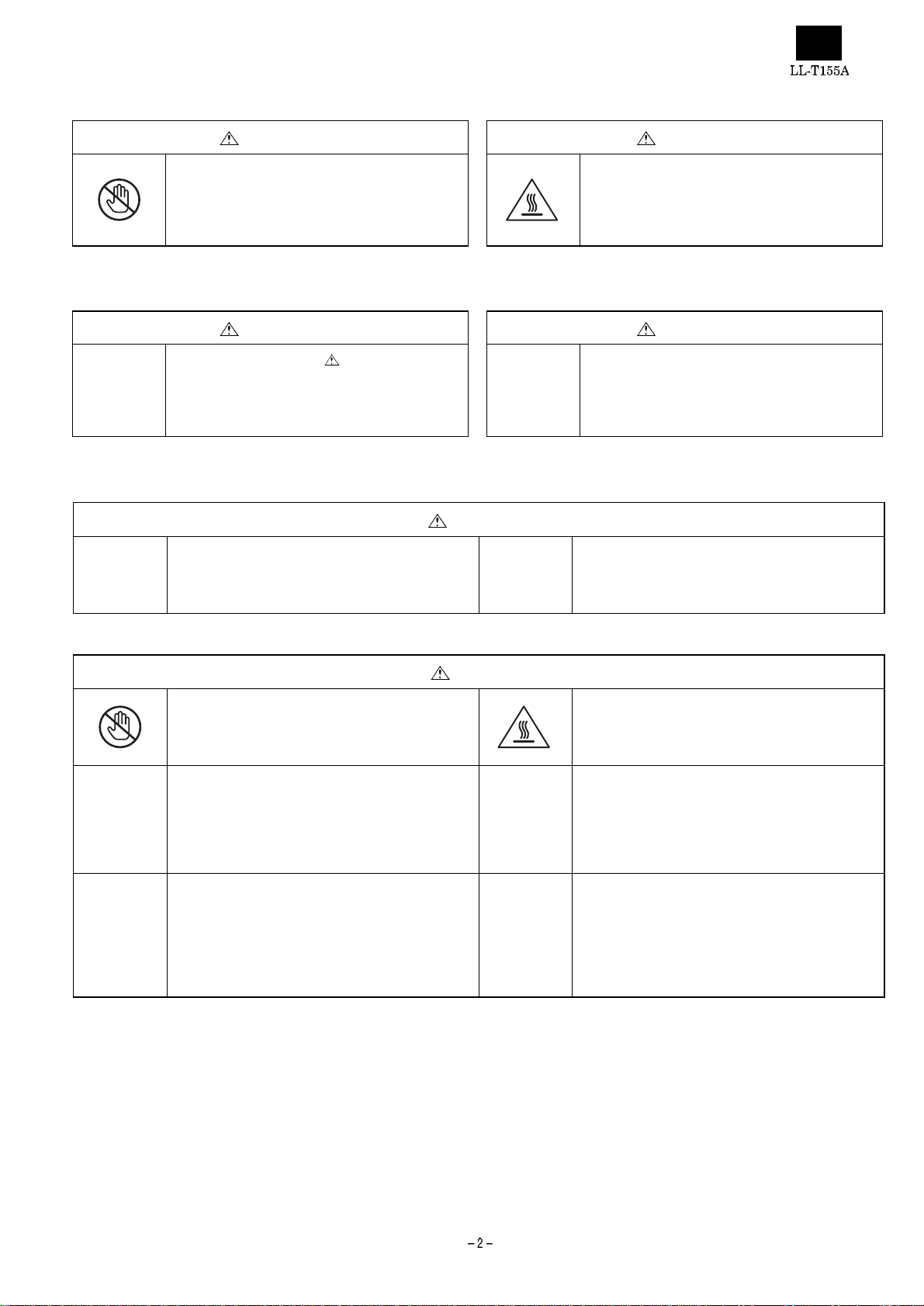
·Cautions to be taken when making adjustments
WARNING CAUTION
1. Use caution to avoid shorts due to the probe of an
oscilloscope or jigs and do not touch high-voltage
circuits directly.
(There is fear of causing a fire or your getting an
electric short accident)
·Cautions to be taken when replacing electrical parts
WARNING CAUTION
1. Parts marked with are important for
maintaining the safety of the product. Use
specified parts when replacement of such parts is
required. (There is fear of giving off smoke,
catching fire, or your getting an electric shock)
·Cautions to be taken when soldering
WARNING
1. Do not try to solder when th e parts are energized or
the unit is turned on.
(There is fear of causing fire or your getting an
electric shock.)
2. Use caution not to touch heating parts like the
radiating plate directly.
(You could get a burn.)
2. Use caution not to damage the LCD unit when
handling it.
2. Use caution not to damage peripheral parts and
lead wires (e.g., burning peeling o f coating).
(There is fear of causing a fire or your getting an
electric shock accident.)
CAUTION
1. Use caution not to touch a soldering iron directly.
(You could get a burn.)
3. Use caution not to have the wrong direction when
installing parts, if they need the installation of a
correct direction.
(There is fear of causing a fire.)
5. Some parts need to be installed at a specified
intervals or by a specified method for safety
purposes (they may be a bit floated from the board
for dissipating heat.). They mu st be reinstalled to
the original conditions.
(There is fear of causing a fire or your getting an
electrical shock accident.)
2. Make sure the radiating plate or heating parts are
cool enough not to get a burn before touching such
a part.
(You could get a burn.)
4. Use caution to avoid shorts due to an improperly
cut length of parts’ lead legs after soldering and
exercise care not to cut your finger with the edge of
cut surface.
(There is fear of causing a fire or your getting an
injury.
6. Use caution to solder in a correct manner so that
areas other than the part you want to solder are
contaminated with solder, like a solder ball or
bridge.
Page 4
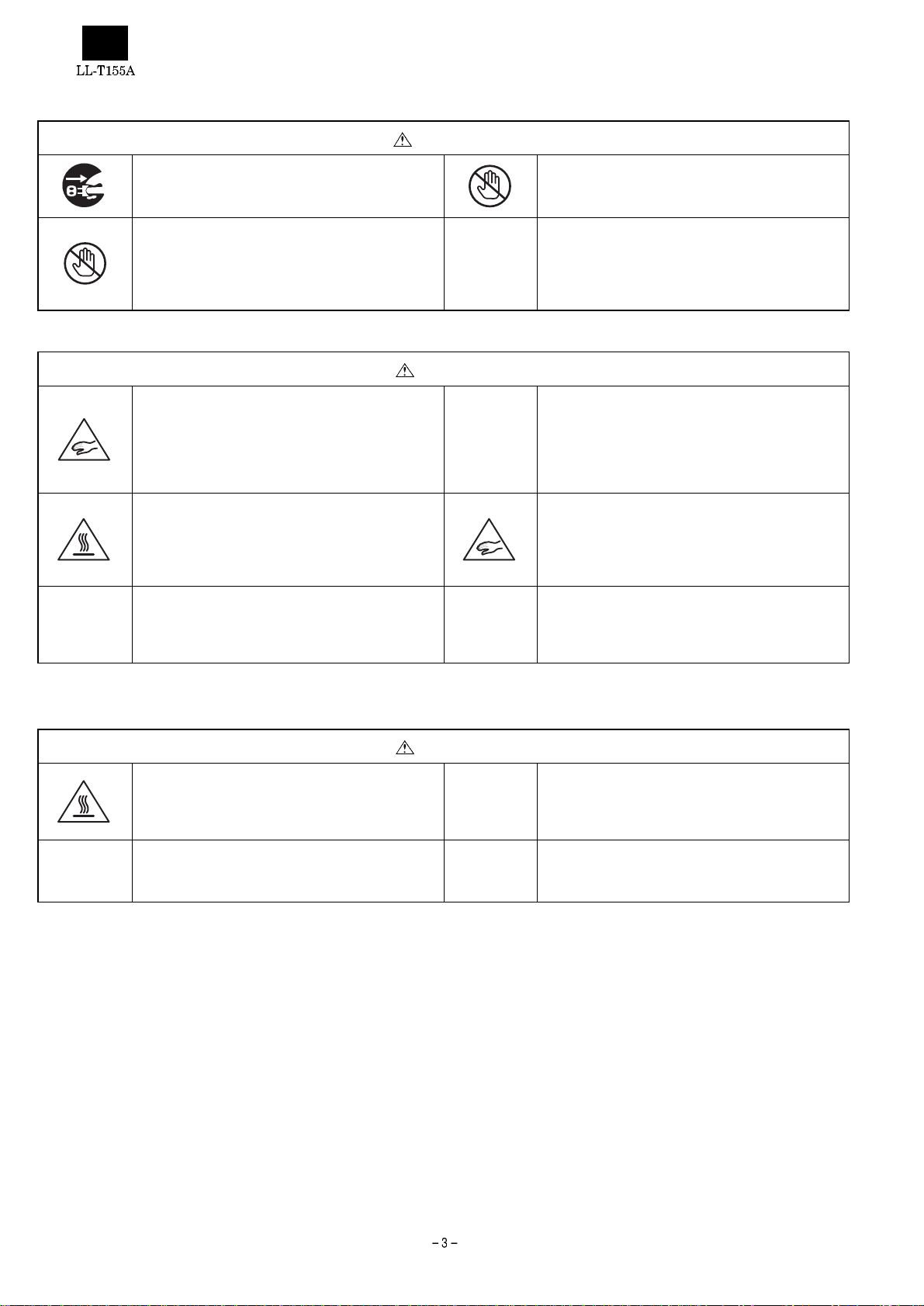
·Cautions to be taken when disassembling or reassembling the unit
WARNING
1. Prior to servicing, make sure to remove the power
supply plug.
(You could get an electrical shock accident.)
3. Before servicing, make sure you know the locations
of high-voltage p art s.
(You could get an electrical shock accident.)
CAUTION
1. When disassembling or reassembling the unit,
make sure to put the front c abinet side (LCD unit
side) downward and carry out work using caution
not to get your fingers caught.
(Since the LCD unit side is heavier, there is fear of
your getting an injury due to tipping or falling.)
3. When disassembling th e unit, use caution not to get
a burn because r adiating plates and areas around
lamps on the PWB are hot immediately after
unplugging.
(You could get a burn.)
5. Pay attention to burrs or edges of the resin (c ab inet
and PWBs) and metal (chassis and others) parts.
(You could cut your finger with them.)
2. Use caution not to touch the inside of the product
with a wet hand or foot.
(You could get an electrical shock accident.)
4. Do not work on an un stab le plac e or with the stan d
put upright. In particular, fix the cabinet before
replacing PWBs or fan.
(There is fear of your getting an injury due to
tipping or falling.
2. Use caution to avoid a reaction due to your
applying too much force when removing or
reinstalling screws.
(You could get an injury.)
4. Use caution not to get you fingers caught in the
stand pole, between the stand and angles or under
the cabinet.
(You could get an injury.)
6. Use caution to the deformation of the grounding
spring or the displacement of the ferrite core.
(There is fear of causing radio noises to other
equipment.)
·Cautions to be taken when replacing fluorescent lamp
CAUTION
1. Make sure the fluorescent lamp is cool enough not
to get a burn before you are going to touch the
lamp or areas around it .
(You could get a burn.)
3. Use caution not to break the fluorescent lamp when
handling it.
(You could get an injury.)
2. Use caution to avoid a reaction due to your
applying too much force when removing the
connector.
(You could get an injury.)
Page 5
CHAPTER1. OTLINE OF HE PRODUCT, NOMENCLATURE AND FUNCTIONS
[1] Features
· 38 cm [15 ty pe] 1024-dots x RGB x 7 68-line high-resolu tion TFT
color LCD panel
· 200 cd/m
2
high-luminance d esign
· Connectable to analog RGB output (for CRT)
Multi display mode function that supports resolutions from 640-dot
x RGB x 400-line to up to 1024-dot x RGB x 768-line
In modes l ower than 800 x 600 dots, it is possib le to enlarge the
screen that offers smooth and excellent visibility.
Supports VESA specification, PC9800 series, Power Ma cin tosh.
· Up to 16 million colors can be displayed.
· Automatic screen adjustment
· The display timing and RGB gain can be more finely adjusted due
to the OSD guide functi on, in addition to the automati c adjustment
function.
· Power management fu nction
· Supports Plug&Play (VESA:DDC1, DDC2B specifications)
[2] Safe servicing and safe inspection,
<When servicing or inspecting,
observe the safety instructions.>
1. Observe the cautions.
Locations which require a special caution carry safety instructions
using labels and stamps on the cabinet, chassis and components.
When servicing, observe the instructions on such labels and
stamps as well as those in the Instruction manual.
2. Exercise care not to get an electric al shock
accident.
Some parts have a high voltage inside the unit. Use caution when
handling them while they are energized.
3. Use specified parts.
The component parts of this unit have safety characteristics such
as flame resistance and dielectric strength. Use replacement parts
which have the same characteristics as those of the components
parts used for th is un it. In particular, component parts marked with
in the cir cuit dr awing parts list ar e imp ortant for m aintain ing th e
safety of the product. Make sure to use specified replacement
parts.
5. Check for safety after servicing.
After finishing servicing, check whether the screws, parts, wires
which have be en r em ove d f or serv ic ing a re r ein s talle d p rop erl y. In
addition, check to see if you have not deteriorated parts around th e
part you serviced, and also check for insulation between each of
the attachment plug terminals and the external metal section.
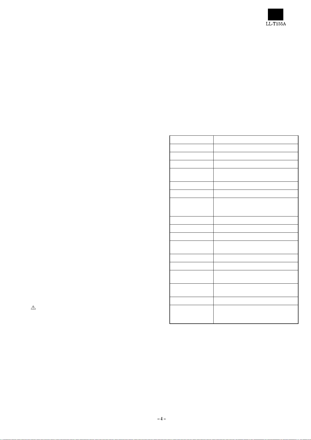
[3] Specifications
1. General specification s
Name of the product: LCD color monitor
Model: LL-T155A, LL-T155B
Item Specifications
LCD display device 38 cm (15 type) TFT color LCD
Picture element pitch 0.297 mm (horizontal) x 0.297 mm (vertical)
Display area 304.1 mm (horizontal) x 228.1 mm (vertical)
Number of picture
elements
Display color approx. 16 million colors (max.)
Input vide signal Analog RGB (0.7 Vp-p/75
Input synchronizing
signal
Input terminal 15-pin mini D-sub connector
USB USB cable relay connector
Plug&Play VESA DDC1/DDC2B
Power management
function
Working temperatu re 5 ~ 35°C
Power supply 100 V AC 50/60 Hz
Power consumption approx. 22 W/ abo ut 3 W in power sav e
Outer dimen sions about 385 mm (width) x 203 mm (depth) x
Weight approx. 6 kg
Accessories AC power supply cord (1), Instruction
1024 x RGB x 768 dots
W )
Horizontal synchronizing sign al TTL level
(positive, negative), vertical synchronizing
signal TTL level (positive, neg ative)
Compatible with VESA DPMS
mode
373 mm (height)
manual (1), warranty (1), adjustment disk
(1), USB cable (1)
4. Reinstall component parts in their original
locations and return wires which have been
rerouted for servicing purposes to their original
positions.
Some component parts use insulating materials such as tubes or
tape for safety purposes, or are mounted, a bit floated, on the
printed wiring bo ard.
When rerouting inside wiring or clamping the wires, use caution not
to bring the wires too close to heati ng or high-voltage pa rts.
Make sure to return inside wiring to their original locations.
· Specifications and a part of the appearance are subject to change
without notice.
Page 6
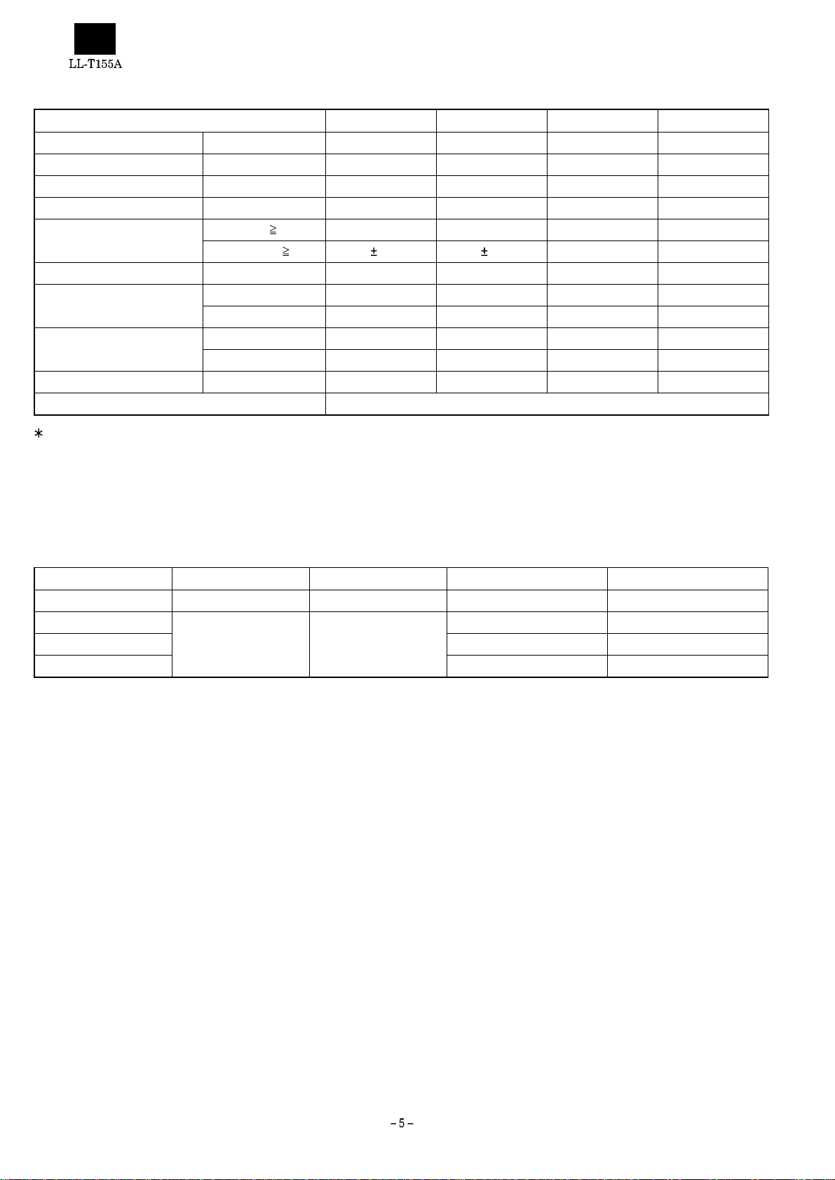
2. Technical specifications
Item MIN TYP MAX Unit
Power supply voltage AC 90 100 110 V
Working temperatur e range +5 — +35 °C
Storing temperature range -20 — +60 °C
Humidity range 20 — 85 %RH
Visual angle range Vertical (CR
Horizontal (CR
Contrast ratio(CR) (
Response speed Leading (
Screen white chromaticity (X) 0.283 0.313 0.343 —
White surface lumina nce (Y
Module model number LQ150X1DH10
Specifications and a part of the appearance are subject to change without notice.
q = 0°) 150 — — —
Trailing (
(Y) 0.299 0.329 0.359 —
) 150 200 — cd/m
L
[Power management]
This unit supports VESA*1 DPMS*2.
To use the power management funct ion of this unit, the video card and
the computer must be compatible with the DPMS specifications.
*1 VESA: Video Electronics Standards Association
*2 DPMS:Display Power Management Signaling
5) +20 ~ -50 +35 ~ -60 — Temperature
5) 50 55 — Temperature
t r) — 10 25 ms
t d) — 35 50 ms
2
DPMS mode Screen condition Power consumption Horizontal synchronizati on Vertical synchronization
ONSTATE Displayed state approx. 22 W Yes Yes
STANDBY
SUSPEND Yes No
OFFSTATE No No
No display approx. 3 W
No Yes
[DDC*3]
This unit supports VESA’s DDC specifications
DDC means a signal specification that offers Plug&Play function to the
monitor and the personal computer.
Information about resolution and others are communicated between
the monitor and the personal computer.
This function is available when the personal computer supports DDC.
There are some DDC types depending on different communication
methods.
This unit supports DDC1 and .DDC2B.
*3 DDC: Display Data Channel
Page 7

[4] Nomenclature and functions
[Front part]
1
1
2
3
Power-on lamp
Light comes on when the power supply is turned on.
The light is green in the normal display mode and orange in the
power save mode.
and buttons
1) Display the adjustment menus.
2) Switch over the adjustment menus (MAIN MANU and SUB
MENU)
3) Change the setting of the adjustment option selected.
DOWN and UP buttons
1) Display the adjustment menus
2) Select adjustment items
[Rear part]
Power supply connector
Make sure to use the AV power supply cord supplied with the unit.
Power supply switch
( | ) : The power is turned on. (T he power-on lamp comes on.)
) : The power is turned off.
(
Signal cable
This cable is used to connect the monitor to the analog RGB output
connector of the computer.
USB DOWN connector
This is sued to connect the monitor to USB devices.
USB UP connector
This is used to connect the monitor to a computer.
CHAPTER2. REPLACING LAMPS
(Removing LCD module)
1. Replacing lamps
· After removi ng the LCD module from the unit according to 2. Re-
moving the LCD modu le, replace the lamp units.
· Replace the lam p units using the following replacemen t procedur e,
referring to Fig.1 (enlarged view) and Fig. 2 (overall view).
· There are two lamp units at the top and bottom of the monitor.
· Wear finger sacks when doing this work, not to contaminate or
damage the LCD panel. Use caut i on prevent the entr an c e of dirt
or dust into the module.
[Replacement procedure]
Turn the module over and remove the screw s A in F igs. 1. (1 screw
for each unit). Put a finger on the concave B and remove the lamp
unit in a straight line.
· Use caution not to apply undue force on the lamp.
Replace the lamp unit with a new one.
Reinstall in the reverse order of disassembly.
· Tighten the screw and make sure the lamp unit won’t move.
Drawing
direction
4
5
21
3
B
Fluorescent
lamp lead wire
Screw A
Fig. 1
Page 8

2. Removing LCD module
Procedure
· Disassembly
1. Remove the 4 screws in
cabinet).
· Use caution not to break the latches in when removing the
front cabinet.
2. Remove the 4 screws in
· Use caution not to drop the LCD module.
3. Remove the 2 screws in
from the module.
· Reassembly
Reassemble the LCD module using the steps from 1 to 3 in reverse.
· Use caution not to get the cables caught in the cabinet when
reassembling.
and remove the display mask (front
and remove the module.
and remove the LCD cable connec tor
1
3
2
4
Page 9

Upper fluorescent lamp lead wire
Screw A (upper)
CN2
CN2
Lower fluorescent lamp
lead wire
Cover
Cover
Tape
Screw A (lower)
Fig. 2
CHAPTER3. CONNECTION, ADJUSTMENT, OPERATION AND FUNCTIONS
Connection to the power supply and the
computer
[Rear part]
· Make sure the computer and the monitor are turned off ( ).
Connect the signal cab le to th e compu ter. Make su re to tig hten the
connector screws.
Connect the AC power supply cord to the monitor. Connect the
other end of the cord to the wall outlet.
Turn the power supply switch on ( | ) to turn on the monitor. Then,
turn on the computer.
When adjustment of the monitor’s picture quality is required, refer to
Paragraph [Adjusting the screen].
Note: Make sure that both the monitor an d compute r are turn ed off
before conn ecting or d isconnecti ng the cord or c able. When
connecting or disconnecting the cord and cable, make sure
1
2
3
to hold their plug, not the cord or cable.
Page 10

Connecting USB cable
[Rear part]
USB DOWN
3
connector
2
USB UP
connector
to computer
USB
device
The monitor has a USB cable relay connector.
The following requirements need to be satisfied in order to use the
USB cable relay connector of this monitor.
· The computer to be connected and its OS (operating system) sup-
ports USB.
· Or a USB hub connected to a computer (and OS) that supports
USB.
When connecting a USB device to the monitor, use the USB cable
supplied with the monitor and follow the steps given below.
Connect the connector at one en d of the USB cable to the USB
DOWN connector of the computer.
Connect the connector at the other end to the USB UP connector
of the monitor.
Connect the cable connected to the USB device to the USB DOWN
connector of the monitor.
1
Press the or button to change the setting of the adjustment
option you selected.
To store the adjustment setting, wait for a while until the adjustment
menu automatically disappear, in the screen mode (resolution, refresh rate or others) for the adjustment.
If any adjustment operation is not carried out for about more than
10 seconds , the adjus tment menu autom atical ly d isapp ear an d the
setting is stored in memory.
If you want to adjust the screen, make an automatic screen adjustment as follows:
Select AUTO ADJUSTMENT from the MAIN MENU and press
or button. The automatic adjustment fu nction starts to
either
automatically adjust the CLOCK, PHASE, HO-POSITION, V-POSITION to the optimal states.
It is necessary to adjust the screen for every screen mode (RESOLUTION, REFRESH RAT, but th e setting is automatic ally stored in
memory and is v alid even after the power is turned off. Once the
adjustment is made, there is no need to adjust thereafter.
If a fine adjus tment of the screen is requi red, use the adjustment
disk (for Windows) supplied with the monitor to make such an adjustment m an ually. If you use an OS other than Windows, you need
to make a fine adjustment of the screen, observing the actual
screen.
How to use the adjustment program
In this manual, the de scriptions are wr itten on the assumption that
you use Windows 95/98.
In addition, it is assumed that the floppy disk drive is drive A.
Insert the attached "Adjustment disk" into drive A.
Open "3.5 inch FD (A):" in "My computer".
(In the case of Windows 3.1, open "File manager" and select drive
A.)
Double click "Adj_uty.exe" to start the adjustment program.
When the adjustment program starts up, the adjustment pattern
shown on the next appears on the screen. Make an adjustment
according to the instructions on the screen.
Note: Some USB device s might not work properly with the com-
puter, OS or per ipheral equipment use d. For the USB support of devices and OS’s, please ask their respective manufacturers or suppliers. The USB device connected to the USB
cable relay connector is operative even if the monit or is in the
power save mode or it is turned off.
Adjustment
In the case of setting up for the first time, or in the case of changin g
the setting of the computer used, it is necessary to adjust the screen.
Adjust the screen in the following manner.
Adjusting procedure:
Press any of the DOWN/ UP/ / buttons to display the MAIN
MENU shown on the ne xt page.
Switch over the two menus (MAIN and SUB) by pr essing the or
button.
Press the DOWN or UP button to select the adjustment item you
want to adjust.
Color pattern
Display frame
White and black
lines alternate.
Screen showing the adjustment program
You can exit the adjustment program by pressing the [Esc] key on
the keyboard of the computer.
When the di spl ay mod e of the co mpu ter us ed is in t he 6 5,0 00- col or
mode, you might see different tones of each color of the color
pattern or a colored gray scale. This is a specificatio n of the input
signal, not a trouble.
Page 11

Adjustment options
Adjustment option 1: MAIN MENU
TO SUB MENU (switching to SUB MENU)
Press the or button to switch over to SUB MENU.
AUTO ADJUSTMENT
Press the or button to start the AUTO ADJUSMENT function, thus
adjusting CLOCK, PHASE, H-POSITION, and V-POSITION to their
respective optimal stat es.
CLOCK
Use the or button to adjust the CLOCK so that you cannot see
vertical stripes-like noses in the pattern where white and black lines
alternate. (See the sketches on the right.)
Vertical stripe-like noise
PHASE
Use the or button to adjust the PHASE so that you can see a clear
white and blac k pattern on the scr een with the horizontal stripes-like
noises minimized.
H-POSITION
The screen moves to the left by pressing the button and to the right
by pressing the
both the frame lines at the right and left edges of the adjustment
pattern.
button. Adjust the H-POSITION so that you can see
V-POSITION
The screen mov e s d ownw ard by pr ess ing th e button an d upw ard by
pressing th e
both the fr ame lines at the to p and bottom edges o f the adjustment
pattern.
button. Adjust the V-POSITION so that you can see
720 x 400 LINE (switching over resolutions)
Use the or button to set the horizontal resolution of the 400-line
screen of PC98 series, US TEXT and other machines.
640 x 400: PC98 series
720 x 400: US TEXT and others
You can switch over the horizontal resolutions of 720 x 400 LINE and
640 x 400 LINE only t hose two modes.
OSD WINDOW LOCATION (movement of adjustment
menu window)
Press the or button to move the adjustment menu on the screen.
RESET
Press the or button to return the screen se ttings to the default
state.
Horizontal stripes-like noise
Adjust the CLOCK first, and then proceed with the adjustment of the
PHASE.
Page 12

Adjustment option 2: SUB MENU
TO MAIN MENU (switching to MAIN MENU)
Press the or button to switch over to MAIN MENU.
AUTO BALANCE
Press or button to function AUTO BALANCE so that the contrast is
automatically optimized. The monitor is factory adjusted for the optimal
condition. However, the adjustment of the contrast may be required
depending on the type of the computer connected. If contrast adjustment is required, use the color pattern in the adjustment program.
Note: There is a possibility that you cannot optimize the contrast
depending on the video output level of the computer used.
COLOR
Use the or button to set the maxi mum number of colors that can
be displayed (approx. 16 million or approx. 260 thousand co lors)
16M: approx. 16 million colors
260K: approx. 260 thousand colors
BRIGHTNESS
Use the or button to adjust the brightness of the entire screen.
Press the
CONTRAST
Press the or butto n to adjust the contrast of the entir e s c re en . U s e
the color pa ttern of the adjustme nt program so that al l tones can be
displayed. Press button to make it weaker and the button to make
stronger.
button to darken and the button to brighten.
RED, GREEN, BLUE
Press the or button to adjust the brightness of each of the
red, green and blue colors.
RED, GREEN, BLUE
Press the or button to adjust the contrast of each of the red,
green and blue colors.
1. Signal timing list
Display mode
31.5 kHz 60 Hz 25.175 MHz
640 x 480
VESA
(IBM AT
compatible
machines and
PC9800 series)
PC-9800 series
640 x 400
US TEXT
720 x 400 31.5 kHz 70 Hz 28.3 MHz
Power Macintosh
640 x 480 35.0 kHz 67 Hz 30.5 MHz
382 x 624 49.7 kHz 74.6 Hz 57.3 MHz
1024 x 768 60.2 kHz 75 Hz 80.0 MHz
The frequencies listed for Power Macintosh are reference values.
For connecting this monitor to Power Macintosh, the conversion
adapter is required.
However, Power Macintosh G3 (Blue & White) model does not
require any conversion adapter.
If a signal timing that is not supported by this monitor is entered, the
message "OUT OF RANGE" appears on the screen for about 5
seconds. In this case, set the computer for any of the signal timings
that are supported by this monitor, referring to the Instruction manual of the computer used.
800 x 600
1024 x 768
37.9 kHz 72 Hz 31.5 MHz
37.5 kHz 75 Hz 31.5 MHz
35.1 kHz 56 Hz 36.0 MHz
37.9 kHz 60 Hz 40.0 MHz
48.1 kHz 72 Hz 50.0 MHz
46.9 kHz 75 Hz 49.5 MHz
48.4 kHz 60 Hz 65.0 MHz
56.5 kHz 70 Hz 75.0 MHz
60.0 kHz 75 Hz 78.75 MHz
24.8 kHz 56 Hz 21.053 MHz
31.5 kHz 70 Hz 25.175 MHz
Non-interlace support only.
2. Connector pin layout
15-pin mini D-sub conn ector
Input connector
Pin No. Function
1 Red video signal input
2 Green video signal input
3 Blue video signal input
4GND
5GND
6 GND for red video signal
7 GND for green video signal
8 GND for blue video signal
9N.C.
10 GND for synchronizing signal
11 GND
12 DDC data
13 Horizontal synchronizing signal input
14 Vertical synchronizing signal input
15 DDC clock
Page 13

CHAPTER4. TROUBLESHOOTING
No power supply
LED comes on in green when
power switch is turned on?
Yes
LED comes on in red.
LED comes on in orange.
Backlight comes on?
Yes
No
No
No
No
Yes
Yes
Is LED in key switch unit normal?
(Check for disconnected cable.)
Is the unit in power save mode (No synchronizing
signal input)
Check if personal computer is turned on?
Check if RGB cable is connected.
Check if synchronizing signal is applied.
Is voltage output to key
switch unit connector
terminal (J4)?
+12 V/+5 V output at power
No
unit connector terminal
CN-JP5) ?
No
Yes
Yes
Key switch unit
defective
Defective
interface unit
No
100 V AC input to power unit
1
Yes
High voltage
*1 output to inverter PWB output
terminal?
Yes
Check LCD module lamp.
Note 1: Note that up to about 1.4 kVrms is applied when the inverter is started or in normal operation.
+12 V and On signal "H" at
inverter terminal (JP5)?
No
input connector?
No
Defective inverter unit
Yes
Check AC
switch and cord.
Defective
power unit
Page 14

Screen is not normal
Check the screen condition by changing the display modes.
Reset the microprocessor to check to see if the screen condition changes.
1
Screen stays in black. Screen stays in white
Check the following signals
(LCD signal input terminals):
+5V power check for LCD
Clock signal
DE signal
H sync/ V sync signal
Jittering screen and
flickering characters
Are OSD adjustment PHASE,
CLOCK settings appropriate?
(If not, adjust according to
Instruction manual.)
Normal
Normal
Abnormal
Abnormal color
Is RGB setting in OSD
adjustment appropriate?
Check LCD signal input terminal
corresponding to the color
condition on screen.
Abnormal
Backlight system normal
LED lights in green
Brighten screen condition.
Under the above conditions,
check LCD signal input terminal.
Abnormal
Normal
Defective interface unit Defective LCD module
Page 15

CHAPTER5. TRIMING AND PROCESSING LEAD WIRES
Step 1
Put the CCF T cable and LCD cab le into shield plate bu shings to
prevent them from getting caught when installing the shield plate.
(Figs. 1 and 2)
Put the CCFT cable at the back of the LCD module to prevent it
from getting cau ght when installing the LCD module.
CCFT cable
Fig. 1 Fig. 2
Step 2
Use caution to prevent the power supply cable and switch cable
from getting caugh t when installing arm rear cover (Fig. 3).
Use caution to prevent the power supply and switch cable from
getting caught when installing the base metal.
Power supply cable
Inverter cable
Power supply cable
Switch cable
LCD cable
Power supply cable
Switch cable
Fig. 3 Fig. 4
Page 16

CHAPTER6. BLOCK DIAGRAM/UNIT TERMINSL
LCD UNIT
LANP
1 LCD SIGNAL INPUT
RGB, H/V
IN PUT
15 inch LCD
LANP
INTERFACE
UNIT
5J1
KEY-SWITCH UNIT
INVERTER
2JP5
4 CN-JP5
3J4
AC 100V
INPUT
POWER UNIT
AC SW
1 5 Connector Symbol Function
AC SOKET
Page 17

Unit terminals
LCD SIGNAL INPUT
Used connector : FX8-60P-SV (HIROSE)
Pin No. Symbol Function
1 GND GND
2 RB0 RED Even-number picture
element signal
3RB1RED
4RB2RED
5RB3RED
6RB4RED
7 RB5 RED (MSB)
8 GND GND
9 GB0 GREEN Even-numb er picture
element signal
10 GB1 GREEN
11 GB2 GREEN
12 GB3 GREEN
13 GB4 GREEN
14 GB5 GREEN (MSB)
15 GND GND
16 BB0 BLUE Even-number picture
element signal
17 BB1 BLUE
18 BB2 BLUE
19 BB3 BLUE
20 BB4 BLUE
21 BB5 BLUE (MSB)
22 GND GND
23 RA0 RED Odd-number picture
element signal
24 RA1 RED
25 RA2 RED
26 RA3 RED
27 RA4 RED
28 RA5 RED (MSB)
29 GND GND
30 GA0 GREEN O dd-number pi cture
element signal
31 GA1 GREEN
32 GA2 GREEN
33 GA3 GREEN
34 GA4 GREEN
35 GA5 GREEN (MSB)
36 GND GND
37 BA0 BLUE Odd-number picture
element signal
38 BA1 BLUE
39 BA2 BLUE
40 BA3 BLUE
41 BA4 BLUE
42 BA5 BLUE (MSB)
43 GND GND
44 REV1 (GND)
45 GND GND
46 Vsync Vertical synchronizing signal
47 Hsync Horizontal synchronizing signal
48 DE Data enable signal
49 GND GND
50 GND GND
51 CKB Sampling clock
(LSB)
(LSB)
(LSB)
(LSB)
(LSB)
(LSB)
Pin No. Symbol Function
52 CKA Sampling clock
53 GND GND
54 GND GND
55 REV2 (GND)
56 REV3 (GND)
57 Vcc +5V power supply
58 Vcc +5V power supply
59 Vcc +5V power supply
60 Vcc +5V power supply
JP5 (To Inver ter Terminal)
Used connector : PH5PS (JST)
Pin No. Symbol Functi on
1 ON / OFF HIGH = ON, LOW = OFF
2NC
3 BRIGHT Brightness control of inverter
4 GND GND
5 +12V B + of inverter
JP4 (To Key Switch Board Termin a l )
Used connector : PH8PS (JST)
Pin No. Symbol Functi on
1NC
2 GND
3LED 1
4LED 2
5DOWN
6 +
7
8UP
–
CN-JP5 (Power Supply Input Terminal)
Used connector : PH6PS (JST)
Pin No. Symbol Functi on
1 +12V +12V supply from power BD
2 +12V +12V supply from power BD
3 GND GND
4 GND GND
5NC
6 Vcc +5V supply from power BD
J1 (Signal Input Terminal)
Used connector : PH12PS (JST)
Pin No. Symbol Functi on
1 SCL DDC
2SDADDC
35VDDC
4 V-SYNC5 H-SYNC
6 GND
7BLUE
8 GND
9 GREEN
10 GND
11 RED
12 GND
Page 18

CHAPTER7. APPEARANCE AND DISASSEMBLY DRAWING OF MECHANISMS
86
24
21
3
31
44
57
32
23
56
85
29
56
29
36
90
26
67
44
51
61
70
60
63
50
59
41
49
20
53
67
44
62
51
33
63
35
52
46
34
91
3733
58
19
84
22
17
77
33
33
33
87
33
6
44
5
43
87
19
33
78
87
79
33
10
33
45
43
2
TP000005
1
36
89
70
4
35
No. Part name Part code New/Conti.
1 Panel, front
2 Panel, rear
3 Base cover
4 Arm, front
5 Arm, rear
New
New
New
New
New
6 Wire ass’y
10 LCD metal ass’y New
17 Interface PWB
New
19 Screw
20 Power PWB New
21 Base controller PWB
22 Wire ass’y New
23 LCD unit
24 Key frame
New
New
26 Rubber, base
29 T-screw
31 Switch, tact
32 LED
33 Screw
34 Connector
35 Connector
36 Screw
37 PCB ass’y New
41 Connector
43 Screw
44 T-screw
45 Cable ass’y New
No. Part name Part code New/Conti.
46 VR
49 Heat sink-1
50 Heat sink-2
51 T-screw
52 Connector
53 Connector
56 T-screw
57 LED holder
58 Switch, locker
59 Connector
60 Wire ass’y
61 Wire ass’y New
62 Wire ass’y
63 Shrink tube
67 Screw
70 Screw New
77 USB A and B
78 Connector
79 Connector
84 Conductive tape
85 Conductive tape
86 Gasket
87 Tape
89 Bracket
90 Bracket
New
New
New
New
New
New
New
New
New
91 Screw
Page 19

CHAPTER8. PACKAGING METHOD
21
3
1
5
ON LCD METAL
13
4
15
11
16
2
8
6
TP000006
No. Part name Part code New/Conti.
1 Power cord
2 End cap R
3 End cap L
4 PE bag
5 PE bag
6Carton New
8 Label, bar code
11 Label, rating
13 Label, bar code
15 Manual New
16 End cap
21 Cable ass’y
New
New
New
New
New
New
New
New
Page 20

COPYRIGHT ã 1999 BY SHARP CORPORATION
All rights reserved.
Printed in Japan.
No part of this publication may be reproduced,
stored in a retrieval system, or transmitted.
In any form or by any means,
electronic, mechanical, photocopying, recording, or otherwise,
without prior written permission of the publisher.
SHARP CORPORATION
Information Systems Group
Quality & Reliability Control Center
Yamatokoriyama, Nara 639-1186, Japan
1999 July Printed in Ja pan
 Loading...