

Page 1
R
LCD MONITOR
LCD FARBMONITOR
MONITEUR LCD
MONITOR LCD
MONITOR LCD
LL-T1511A
LL-T1501A
OPERATION MANUAL
BEDIENUNGSANLEITUNG
MODE D’EMPLOI
MANUALE D’USO
MANUAL DE FUNCIONAMIENTO
(Figure shown is LL-T1511A.)
(Die Abbildung zeigt das Modell LL-T1511A.)
(Le modèle illustré ici est le LL-T1511A.)
(La figura illustrata è LL-T1511A.)
(La ilustración muestra el modelo LL-T1511A.)
Page 2

Table of Contents / Inhaltsverzeichnis / Table des matières / Indice / Índice
English . . . . . . . . . . . . . . . . . . . . . . . . . . . . . . . . . . . . . . . . . . . . . . . . . . . . . . . . . . . . . . . . . . . . . . . . 3
Deutsch . . . . . . . . . . . . . . . . . . . . . . . . . . . . . . . . . . . . . . . . . . . . . . . . . . . . . . . . . . . . . . . . . . . . . . 27
Français . . . . . . . . . . . . . . . . . . . . . . . . . . . . . . . . . . . . . . . . . . . . . . . . . . . . . . . . . . . . . . . . . . . . . . 51
Italiano . . . . . . . . . . . . . . . . . . . . . . . . . . . . . . . . . . . . . . . . . . . . . . . . . . . . . . . . . . . . . . . . . . . . . . . 75
Español . . . . . . . . . . . . . . . . . . . . . . . . . . . . . . . . . . . . . . . . . . . . . . . . . . . . . . . . . . . . . . . . . . . . . . 99
2
Page 3

Table of Contents
Notice for Users in the USA . . . . . . . . . . . . . . . . . . . . . . . . . . . . . . . . . . . . . . . . . . . . . . . . . . . . . . . . . . . 4
TCO'99. . . . . . . . . . . . . . . . . . . . . . . . . . . . . . . . . . . . . . . . . . . . . . . . . . . . . . . . . . . . . . . . . . . . . . . . . . . 5
Notice for Users in Europe . . . . . . . . . . . . . . . . . . . . . . . . . . . . . . . . . . . . . . . . . . . . . . . . . . . . . . . . . . . . 7
Notice for Users in the UK . . . . . . . . . . . . . . . . . . . . . . . . . . . . . . . . . . . . . . . . . . . . . . . . . . . . . . . . . . . . 8
Notice for Users in Australia. . . . . . . . . . . . . . . . . . . . . . . . . . . . . . . . . . . . . . . . . . . . . . . . . . . . . . . . . . . 8
Tips and safety precautions . . . . . . . . . . . . . . . . . . . . . . . . . . . . . . . . . . . . . . . . . . . . . . . . . . . . . . . . . . . 9
Product description . . . . . . . . . . . . . . . . . . . . . . . . . . . . . . . . . . . . . . . . . . . . . . . . . . . . . . . . . . . . . . . . 10
Connecting the monitor and turning the monitor on and off . . . . . . . . . . . . . . . . . . . . . . . . . . . . . . . . . . 12
Connecting the monitor to a computer (PC etc.). . . . . . . . . . . . . . . . . . . . . . . . . . . . . . . . . . . . . . . 12
Connecting the monitor to a power source . . . . . . . . . . . . . . . . . . . . . . . . . . . . . . . . . . . . . . . . . . . 12
Turning the power on. . . . . . . . . . . . . . . . . . . . . . . . . . . . . . . . . . . . . . . . . . . . . . . . . . . . . . . . . . . . 12
Turning the power off. . . . . . . . . . . . . . . . . . . . . . . . . . . . . . . . . . . . . . . . . . . . . . . . . . . . . . . . . . . . 15
Connecting a USB device . . . . . . . . . . . . . . . . . . . . . . . . . . . . . . . . . . . . . . . . . . . . . . . . . . . . . . . . 15
Adjusting the screen display. . . . . . . . . . . . . . . . . . . . . . . . . . . . . . . . . . . . . . . . . . . . . . . . . . . . . . . . . . 16
Automatic screen adjustment . . . . . . . . . . . . . . . . . . . . . . . . . . . . . . . . . . . . . . . . . . . . . . . . . . . . . 16
Adjusting the backlight . . . . . . . . . . . . . . . . . . . . . . . . . . . . . . . . . . . . . . . . . . . . . . . . . . . . . . . . . . 17
Manual screen adjustment . . . . . . . . . . . . . . . . . . . . . . . . . . . . . . . . . . . . . . . . . . . . . . . . . . . . . . . 18
Monitor care and repair . . . . . . . . . . . . . . . . . . . . . . . . . . . . . . . . . . . . . . . . . . . . . . . . . . . . . . . . . . . . . 21
Monitor care . . . . . . . . . . . . . . . . . . . . . . . . . . . . . . . . . . . . . . . . . . . . . . . . . . . . . . . . . . . . . . . . . . 21
Storage . . . . . . . . . . . . . . . . . . . . . . . . . . . . . . . . . . . . . . . . . . . . . . . . . . . . . . . . . . . . . . . . . . . . . . 21
Troubleshooting. . . . . . . . . . . . . . . . . . . . . . . . . . . . . . . . . . . . . . . . . . . . . . . . . . . . . . . . . . . . . . . . 21
Specifications . . . . . . . . . . . . . . . . . . . . . . . . . . . . . . . . . . . . . . . . . . . . . . . . . . . . . . . . . . . . . . . . . . . . . 22
Instructions for installing a VESA compliant arm . . . . . . . . . . . . . . . . . . . . . . . . . . . . . . . . . . . . . . . . . . 25
English
3
Page 4

Notice for Users in the USA
FCC Statement
WARNING – FCC Regulations state that any unauthorized changes or modifications to this equipment
not expressly approved by the manufacturer could void the user's authority to operate this equipment.
Note: This equipment has been tested and found to comply with the limits for a Class B digital device
pursuant to Part 15 of the FCC Rules.
These limits are designed to provide reasonable protection against harmful interference in a residential
installation. This equipment generates, uses and can radiate radio frequency energy and, if not installed
and used in accordance with the instructions, may cause harmful interference to radio communications.
However, there is no guarantee that interference will not occur in a particular installation. If this
equipment does cause harmful interference to radio or television reception, which can be determined by
turning the equipment off and on, the user is encouraged to try to correct the interference by one or more
of the following measures:
– Reorient or relocate the receiving antenna.
– Increase the distance between the equipment and receiver.
– Connect the equipment into an outlet on a circuit different from that to which the receiver is connected.
– Consult the dealer or an experienced radio/TV technician for help.
Use nothing but the included cables and A C cord to insure compliance with FCC regulation for Class B
computing equipment.
Declaration of Conformity
SHARP LCD Color Monitor LL-T1511A,LL-T1501A
This device complies with part 15 of the FCC rules. Operation is subject to the following conditions: (1)
this device may not cause harmful interference , and (2) this device must accept any interference
received, including interference that ma y cause undersiz ed operation.
Responsible Party : SHARP ELECTRONICS CORPORATION
Sharp Plaza, Mahwah, New Jersey 07430
TEL :1-800-BE-SHARP
* As an ENERGY STAR Partner , SHARP has determined that this product meets the ENERGY STAR
guidelines for energy efficiency.
This product utilizes tin-lead solder, and fluorescent lamp containing a small amount of mercury. Disposal
of these materials may be regulated due to environmental considerations. For disposal or recycling
information, please contact your local authorities or the Electronics Industries Alliance:www.eiae.org
4
Page 5

Congratulations!
You hav e just purchased a TCO'99 approved and labelled product! Your choice has pro vided you with a
product developed for professional use. Your purchase has also contributed to reducing the burden on the
environment and also to the further development of environmentally adapted electronics products .
Why do we have en vironmentally labelled computers?
In many countries, environmental labelling has become an established method f or encour aging the
adaptation of goods and services to the environment. The main problem, as far as computers and other
electronics equipment are concerned, is that environmentally harmful substances are used both in the
products and during their manufacture. Since it is not so far possible to satisf actorily recycle the majority of
electronics equipment, most of these potentially damaging substances sooner or later enter nature.
There are also other characteristics of a computer, such as energy consumption levels, that are important
from the viewpoints of both the work (internal) and natural (external) environments. Since all methods of
electricity generation have a negativ e eff ect on the en vironment (e .g. acidic and climate-influencing
emissions, radioactive waste), it is vital to sa ve energy . Electronics equipment in offices is often left running
continuously and thereby consumes a lot of energy.
English
What does labelling inv olve?
This product meets the requirements for the TCO'99 scheme which pro vides for international and
environmental labelling of personal computers. The labelling scheme was de veloped as a joint effort by the
TCO (The Swedish Confederation of Professional Employees), Svenska Naturskyddsforeningen (The
Swedish Society for Nature Conservation) and Statens Energimyndighet (The Swedish National Energy
Administration).
Approval requirements cov er a wide range of issues: environment, ergonomics, usability, emission of electric
and magnetic fields, energy consumption and electrical and fire safety.
The environmental demands impose restrictions on the presence and use of heavy metals, brominated and
chlorinated flame retardants, CFCs (freons) and chlorinated solvents, among other things. The product must
be prepared for recycling and the manufacturer is obliged to have an environmental policy which must be
adhered to in each country where the company implements its operational policy.
The energy requirements include a demand that the computer and/or display, after a certain period of
inactivity, shall reduce its power consumption to a lower level in one or more stages. The length of time to
reactivate the computer shall be reasonable f or the user.
Labelled products must meet strict environmental demands, for example, in respect of the reduction of
electric and magnetic fields, physical and visual ergonomics and good usability.
Below you will find a brief summary of the environmental requirements met by this product. The complete
environmental criteria document may be ordered from:
5
Page 6

TCO Development
SE-114 94 Stockholm, Sweden
Fax: +46 8 782 92 07
Email (Internet): dev elopment@tco .se
Current information regarding TCO'99 approved and labelled products may also be
obtained via the Internet, using the address: http://www .tco-inf o.com/
Environmental requirements
Flame retardants
Flame retardants are present in printed circuit boards, cables, wires, casings and housings. Their purpose is
to prevent, or at least to delay the spread of fire. Up to 30% of the plastic in a computer casing can consist of
flame retardant substances. Most flame retardants contain bromine or chloride, and those flame retardants
are chemically related to another group of environmental toxins , PCBs. Both the flame retardants containing
bromine or chloride and the PCBs are suspected of giving rise to severe health effects , including
reproductive damage in fish-eating birds and mammals, due to the bio-accumulativ e* processes . Flame
retardants have been f ound in human b lood and researchers fear that disturbances in foetus dev elopment
may occur.
The relevant TCO'99 demand requires that plastic components weighing more than 25 grams must not
contain flame retardants with organically bound bromine or chlorine. Flame retardants are allow ed in the
printed circuit boards since no substitutes are available .
Cadmium**
Cadmium is present in rechargeable batteries and in the colour-generating lay ers of certain computer
displays. Cadmium damages the nervous system and is toxic in high doses. The relevant TCO'99
requirement states that batteries, the colour-generating layers of display screens and the electrical or
electronics components must not contain any cadmium.
Mercury**
Mercury is sometimes found in batteries, relays and switches . It damages the nervous system and is toxic in
high doses. The relevant TCO'99 requirement states that batteries may not contain any mercury. It also
demands that mercury is not present in any of the electrical or electronics components associated with the
labelled unit. There is howev er one exception. Mercury is, for the time being, permitted in the back light
system of flat panel monitors as there today is no commercially av ailable alternative. TCO aims on removing
this exception when a mercury free alternative is availab le.
CFCs (freons)
The relevant TCO'99 requirement states that neither CFCs nor HCFCs may be used during the manufacture
and assembly of the product. CFCs (freons) are sometimes used for washing printed circuit boards. CFCs
break down ozone and thereby damage the ozone layer in the stratosphere, causing increased reception on
earth of ultraviolet light with e.g. increased risks of skin cancer (malignant melanoma) as a consequence.
Lead**
Lead can be found in picture tubes, displa y screens , solders and capacitors . Lead damages the nervous
system and in higher doses, causes lead poisoning. The relevant TCO´99 requirement permits the inclusion
of lead since no replacement has yet been dev eloped.
*
Bio-accumulative is defined as substances which accumulate within living organisms
**
Lead, Cadmium and Mercury are heavy metals which are Bio-accumulative.
6
Page 7

Notice for Users in Europe
This equipment complies with the requirements of Directives 89/336/EEC and 73/23/EEC as amended by
93/68/EEC.
Dieses Gerät entspricht den Anforderungen der EG-Richtlinien 89/336/EWG und 73/23/EWG mit
Änderung 93/68/EWG.
Ce matériel répond aux exigences contenues dans les directives 89/336/CEE et 73/23/CEE modifiées
par la directive 93/68/CEE.
Dit apparaat voldoet aan de eisen van de richtlijnen 89/336/EEG en 73/23/EEG, ge wijzigd door 93/68/
EEG.
Dette udstyr overholder kra v ene i direktiv nr. 89/336/EEC og 73/23/EEC med tillæg nr. 93/68/EEC.
Quest' apparecchio è conforme ai requisiti delle direttive 89/336/EEC e 73/23/EEC, come emendata dalla
direttiva 93/68/EEC.
Η εγκατασταση ανταποκρινεται στιζ απαιτησειζ των οδηγιων τηζ Ευρωπαïκηζ Ενωσηζ 89/336/ΕΟΚ κατ 73/23/ΕΟΚ,
óπωζ οι κανονισµοι αυτοι συµπληρωθηκαν απó την οδηγια 93/68/ΕΟΚ.
Este equipamento obedece às exigências das directivas 89/336/CEE e 73/23/CEE, na sua v ersão
corrigida pela directiva 93/68/CEE.
Este aparato satisface las e xigencias de las Directivas 89/336/CEE y 73/23/CEE, modificadas por medio
de la 93/68/CEE.
English
Denna utrustning uppfyller kraven enligt riktlinjerna 89/336/EEC och 73/23/EEC så som komplette ras av
93/68/EEC.
Dette produktet oppfyller betingelsene i direktivene 89/336/EEC og 73/23/EEC i endringen 93/68/EEC.
Tämä laite täyttää direktiivien 89/336/EEC ja 73/23/EEC v aatimukset, joita on muutettu direktiivillä 93/68/
EEC.
CAUTION :
TO PREVENT ELECTRICAL SHOCK, DISCONNECT THE AC CORD BEFORE SER VICING.
CAUTION :
FOR A COMPLETE ELECTRICAL DISCONNECTION, PULL OUT THE MAIN PLUG.
VORSICHT :
UM DIE STROMZUFUHR VOLLSTÄNDIG ZU UNTERBRECHEN, DEN NETZSTECKER HERAUSZIEHEN
ENTFERNEN.
ATTENTION :
POUR UN ARRET TOTAL DU SYSTEMS, DECONNECTEZ LA PRISE DE COURANT SECTEUR.
VARNING :
FÖR TOTAL ELEKTRISK URKOPPLING, KOPPLA UR KONTAKTEN OCH.
PRECAUCION :
PARA UNA COMPLETA DESCONEXION ELECTRICA DESENCHUFE LA CLAVIJA DE LA RED.
7
Page 8
Notice for Users in the UK
FOR CUSTOMERS IN U.K.
IMPORTANT
The wires in this mains lead are coloured in accordance with the following code :
GREEN-AND-YELLOW : Earth
BLUE : Neutral
BROWN : Live
As the colours of the wires in the mains lead of this apparatus may not correspond with the coloured
markings identifying the terminals in your plug proceed as follows. The wire which is coloured GREENAND-YELLOW must be connected to the terminal in the plug which is marked by the letter E or by the
safety earth or coloured green or green-and-yellow.
The wire which is coloured BLUE must be connected to the terminal which is marked with the letter N
or coloured black.
The wire which is coloured BROWN must be connected to the terminal which is marked with the letter
L or coloured red.
Ensure that your equipment is connected correctly-if you are in any doubt consult a qualified
electrician.
"WARNING :THIS APPARATUS MUST BE EARTHED"
Notice for Users in Australia
Service Inquiries
Please contact your dealer for service if required or contact Sharp Corporation of Australia on
1 300 13 50 22 for referr al to y our nearest Sharp authorized Service Center.
8
Page 9

Tips and safety precautions
• Under certain display conditions, minute specks
or spots may be noticeable. This is common for
liquid crystal monitors and is not a malfunction.
• The LCD panel has been manufactured using
highly elaborate technology. Properly working
pixels comprise 99.99% of total pixels. However,
please understand that 0.01% or less of pixels
may be missing or be brighter than usual.
• Do not leave the screen displaying idly for long
periods of time, as this could cause afterimage to
remain.
• If the brightness is adjusted to the minimum
setting it may be difficult to see the screen.
• The quality of the computer signal may influence
the quality of the display. We recommend using a
computer able to emit high quality video signals.
• Never rub or tap the monitor with hard objects.
• Please understand that Sharp Corporation bears
no responsibility for errors made during use by
the customer or a third party, nor for any other
malfunctions or damage to this product arising
during use, except where indemnity liability is
recognized under law.
• This monitor and its accessories may be
upgraded without advance notice.
Location
• Do not use the monitor where ventilation is poor ,
where there is a lot of dust, where humidity is
high, or where the monitor may come into contact
with oil or steam, as this could lead to fire.
• Ensure that the monitor does not come into
contact with water or other fluids. Ensure that no
objects such as paper clips or pins enter the
monitor as this could lead to fire or electric
shock.
• Do not place the monitor on top of unstable
objects or in unsafe places. Do not allow the
monitor to come into contact with strong shocks
or vibrations. Causing the monitor to fall or topple
over ma y damage it.
• Do not use in places where the monitor will be
subject to direct sunlight, near heating equipment
or anywhere else where there is likelihood of high
temperature, as this may lead to generation of
excessive heat and outbreak of fire.
The Power Cord
• Do not damage the power cord nor place heavy
objects on it, stretch it or overly bend it. Also, do
not add extension cords. Damage to the cord
may result in fire or electric shock.
• Insert the power plug directly into the AC outlet.
Adding an extension cord may lead to fire as a
result of overheating.
Monitor and accessory checklist
• Please check that the following items are
included in the package.
• LCD monitor (1)
• USB cable (1)
• Monitor Settings Adjustment Disk for
Windows (1)
• Operation manual (1)
Notes:
• You are advised to retain the carton in case the
monitor needs to be transported.
• Authorship rights to the Monitor Settings
Adjustment Disk’s program are held by Sharp
Corporation. Do not reproduce it without
permission.
Manual Scope
• This booklet is the operation manual for both LLT1511A and LL-T1501A. Unless specifically
indicated, the explanation refers to both devices,
and the figure shown is LL-T1511A. Where the
instructions differ for each device type, the device
name is indicated.
• In this booklet, Microsoft Windows 2000 will be
referred to as [Windows2000], Microsoft
Windows Millenium as [WindowsMe], Microsoft
Windows 98 as [Windows98], Microsoft Windo ws
95 as [Windows95], and Microsoft Windows
V ersion 3.1 as [Windows3.1]. When there is no
need to distinguish between programs, the term
[Windows] will be used.
• Microsoft and Windows are registered
trademarks of Microsoft Corporation.
• Macintosh is a registered trademark of Apple
Computer, Inc.
English
9
Page 10
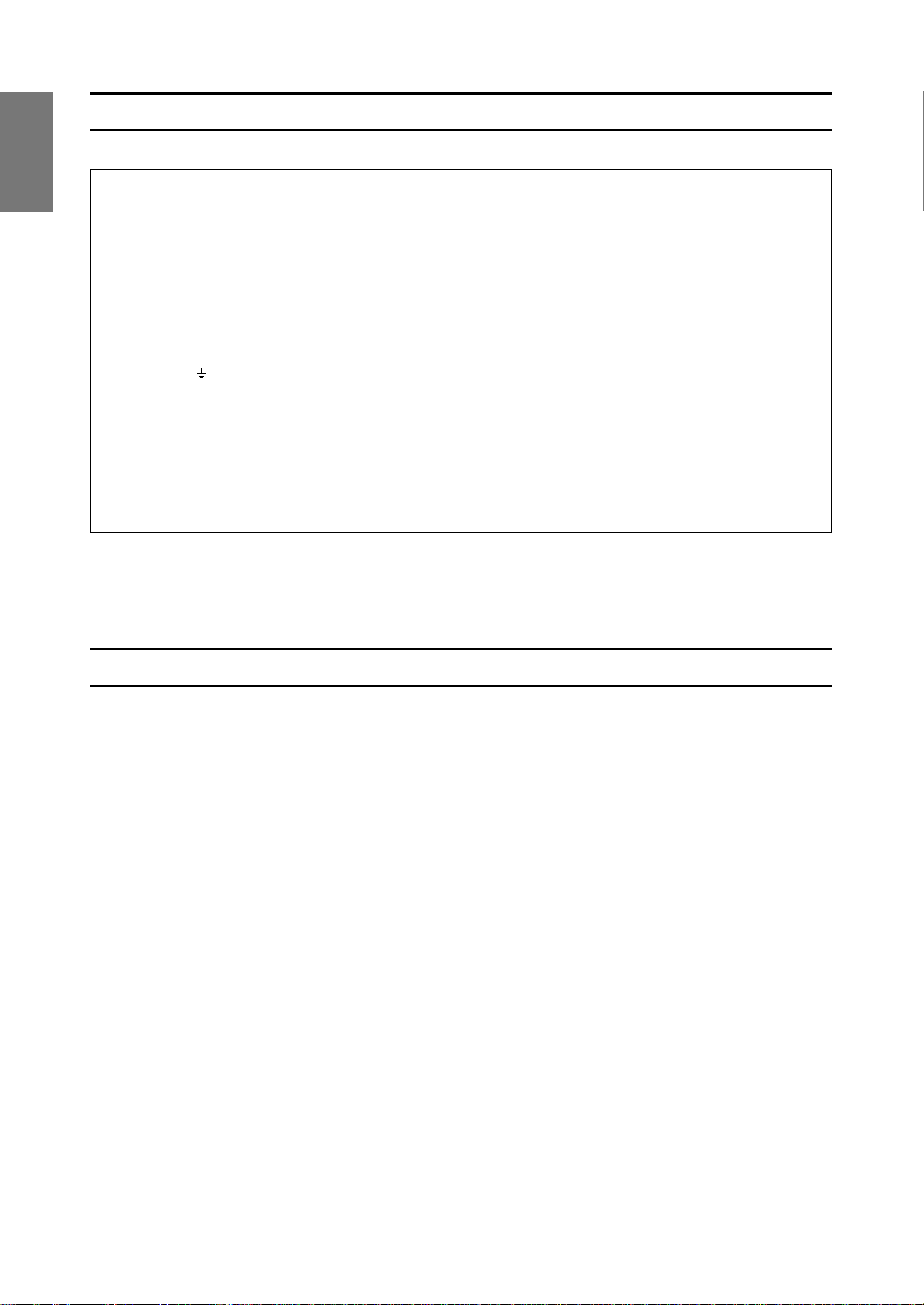
Product description
Front view
1. Power button Pressing this button turns the power on when the main power switch (p. 11) is
on. (After turning the power on, it may take a little time before the screen displays.) Press the b utton again to turn the power off.
2. Power LED This LED is lit green when in use and orange when in power-sa ving mode.
buttons When the On Screen Display (OSD) Menu is displayed:
3.
4. SELECT button Selects the menu option to be adjusted.
5. MENU button This button is used to pop-up, select and close the OSD Menu.
These buttons are used to increase or decrease the value of a selected option.
When the OSD Menu is not displayed:
These buttons are used to adjust backlight brightness.
LL-T1511A LL-T1501A
126543 7
1254 3
6. BRIGHT button This button is used to change the backlight to any of three levels of brightness.
(LL-T1511A only.)
7. Brightness sensor Measures the brightness of the surrounding environment.
(LL-T1511A only.)
Adjusting the angle of the monitor
Lightly holding both sides of the monitor, adjust
it to a suitable viewing angle.
On [AUTO] setting the brightness sensor will automatically adjust to the right
brightness.
30°
30°
30°
10
Page 11
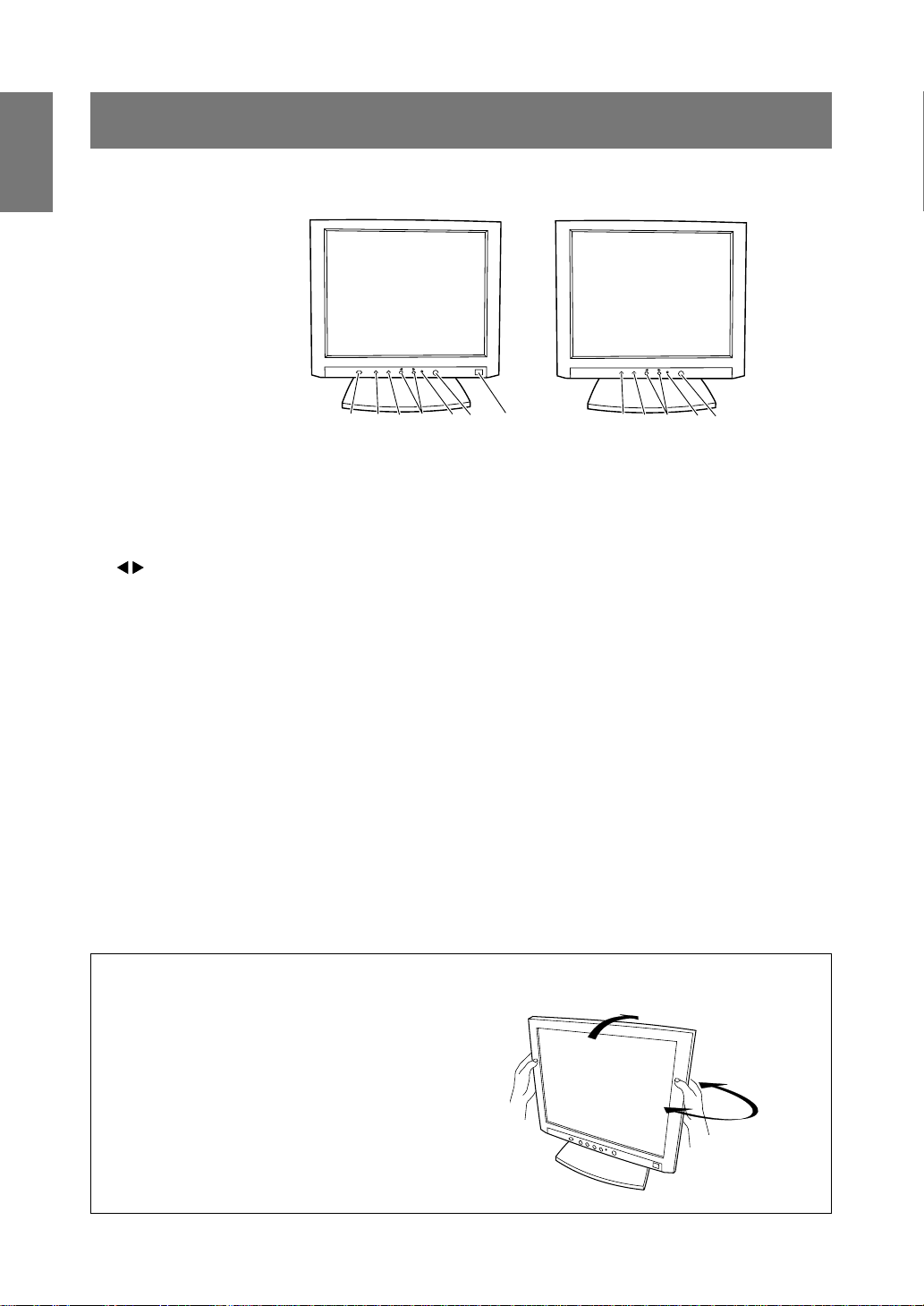
Product description
Rear View
USB port: Upstream (1 Port)
A USB-ready computer or
self-powered USB hub can be
connected here.
Ventilation
openings
Security lock anchor
By connecting a security lock (purchased separately) to the security lock anchor, the monitor is
fixed so that it cannot be transported.
The theft prevention hole works in conjunction with
Kensington Micro Saver Security Systems.
Note: Never block the
ventilation openings as this
may lead to overheating
inside the monitor and result
in malfunction
Power connector
The power cord is
connected here.
RGB signal cable
This is to be connected to
the computer's analog RGB
output terminal.
English
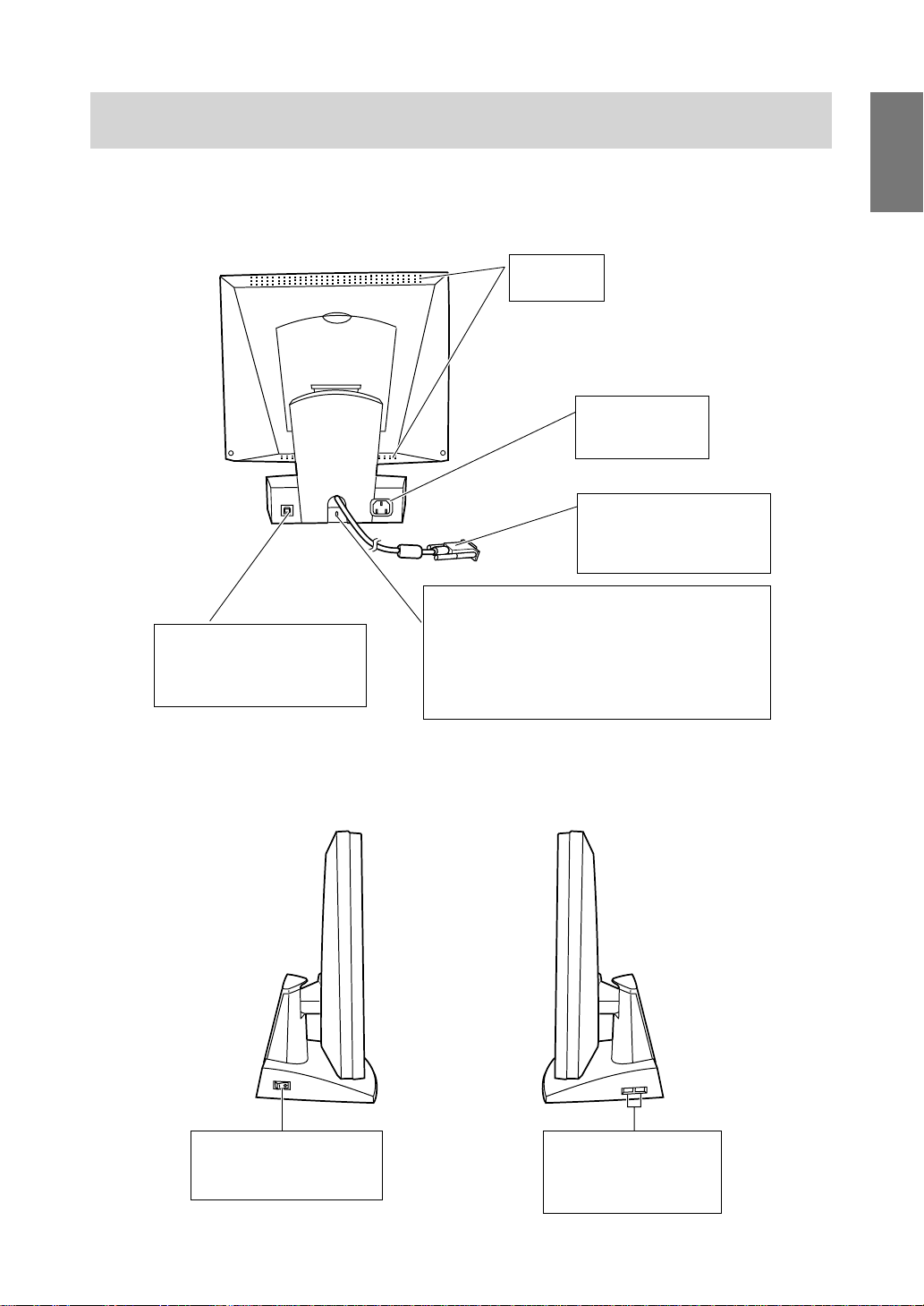
Side view
Main power switch
(I) Turns the monitor on.
(O) Turns the monitor off.
USB port: Downstream
(2 ports)
A USB device can be connected here.
11
Page 12
Connecting the monitor and turning
the monitor on and off
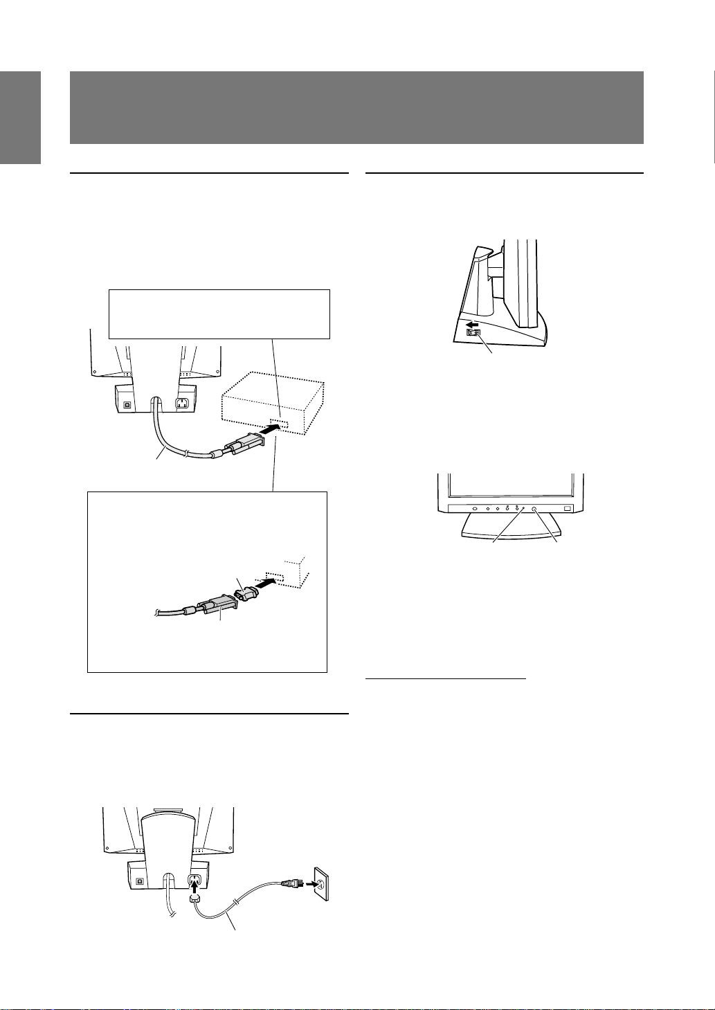
Connecting the monitor to a computer
(PC etc.)
When connecting, ensure that both the monitor and
computer are switched off.
Firmly insert the analog RGB output
terminal (mini D-sub 15 pin with 3 rows)
then tighten the screws each side.
RGB cable
If connecting to a D-sub 15 pin 2 row Apple
Power Macintosh, attach a Macintosh conversion adapter (to be purchased separately) to
the RGB signal cable.
Macintosh conversion adapter
RGB signal cable
After connecting the adapter, tighten the
screws on each side to fix into place.
Connecting the monitor to a power source
Before connecting, first turn off the monitor's main
power switch.
AC outlet
2
1
Turning the power on
1. Turn on the monitor's main switch.
Main power switch
2. Turn on the computer.
3. Press the monitor's power button. The power
LED will be lit green, and the screen will display
an image.
Power LED
Note:
• When setting up this monitor for the first time or
after having changed an aspect of the current
system, perform an automatic screen adjustment
before use (p . 16).
Installing set-up information
Depending on the computer or OS, it may be necessary to use the computer to operate the installation
of monitor set-up information etc. If so, follow the
steps below to install the monitor set-up information.
Notes:
• Depending on the computer type, command
names and methods may differ. Please follow the
computer’s own oper ation manual while reading
this.
• This explanation assumes that the floppy disk
drive is "A drive". If the floppy disk drive of your
computer is not "A drive", please read the below
substituting the floppy disk drive y ou are using in
place of "A drive" or "A ".
Power button
Power cord
12
Page 13

Connecting the monitor and turning the monitor on and off
For Windows95
Installing monitor set-up information into Windows95.
This explanation assumes that the floppy disk driv e
is "A drive".
1. Place the Monitor Settings Adjustment Disk
(provided) into the computer's A drive.
2. Click on the [Start] button. From [Settings],
choose [Control Panel].
3. Double click on [Display].
4. Click on [Settings], [Advanced Properties], and
[Monitor], then [Change].
5. Click on [Have Disk], confirm that [Copy manufacturer's files from:] is [A:] then click [OK].
6. Confirm that the monitor details are selected, and
click [OK].
7. Check that the monitor details are displayed, then
click [Apply].
8. Click [OK], and close the window.
9. Remove the Monitor Settings Adjustment
Disk from the A drive.
For Windows98
Installing monitor set-up information into Windows98.
If the "Add New Hardware Wizard" has appeared:
(This explanation assumes that the floppy disk driv e
is "A drive")
1. Place the Monitor Settings Adjustment Disk
(provided) into the computer's A drive.
2. Click [Next].
3. Check [Display a list of all the drivers in a specific
location, so you can select the driver you w ant.],
then click [Next].
4. When [Models] is displayed, click on [Have Disk],
confirm that [Copy manufacturer's files from:] is
[A:], and click [OK].
5. Confirm that the monitor details are selected,
then click [Next], [Next], and [Finish]. If the "Add
New Hardware Wizard" appears, repeat the
installation commands beginning from 2 above.
6. Remove the Monitor Settings Adjustment Disk
from the A drive.
If the "Add New Hardware Wizard" has not appeared:
(This explanation assumes that the floppy disk driv e
is "A drive")
1. Place the Monitor Settings Adjustment Disk in the
computer's A drive.
2. Click on the [Start] button. From [Settings],
choose [Control Panel].
3. Double click on [Display].
4. Click on [Settings], [Advanced] and [Monitor].
5. In [Options], check [Automatically detect Plug &
Play monitors] and click on [Change].
6. Click [Next].
7. Click on [Display a list of all the drivers in a
specific location, so you can select the driver you
want.], then click [Next].
8. When [Models] is displayed, click on [Have Disk],
confirm that [Copy manufacturer's files from:] is
[A:], and click [OK].
9. Confirm that the monitor details are selected,
then click [Next], [Next], and [Finish].
10.Check that the monitor details are display ed, then
click [Apply].
11.Click [OK], and close the window.
12.Remove the Monitor Settings Adjustment Disk
from the A drive.
English
13
Page 14

Connecting the monitor and turning the monitor on and off
For Windows2000
Installing monitor set-up information into Windows2000.
This explanation assumes that the floppy disk driv e
is "A drive".
1. Place the Monitor Settings Adjustment Disk
(provided) into the computer's A drive.
2. Click on the [Start] button. From [Settings],
choose [Control Panel].
3. Double click on [Display].
4. Click on [Settings], [Advanced] and [Monitor].
5. Click on [Properties], [Driver] and [Update
Driver].
6. When [Upgrade Device Driver Wizard] appears,
click [Next].
7. Check [Display a list of the known driv ers for this
device so that I can choose a specific driver] and
click [Next].
8. When [Models] is displayed, click on [Have Disk],
confirm that [Copy manufacturer's files from:] is
[A:], and click [OK].
9. Select the monitor from the list displayed and
click [Next].
10.Click [Next], confirm that the monitor's name
appears on the screen, and click [Finish]. If
[Digital Signature Not Found] appears, click [Yes].
11.Click on [Close].
12.Click [OK], and close the window .
13.Remove the Monitor Settings Adjustment Disk
from the A drive.
For WindowsMe
Installing monitor set-up information into
WindowsMe.
If the "Add New Hardware Wizard" has appeared:
(This explanation assumes that the floppy disk driv e
is "A drive")
1. Place the Monitor Settings Adjustment Disk
(provided) into the computer's A drive.
2. Check [Specify the location of the driver [Advanced]] and click [Next].
3. Check [Display a list of all the drivers in a specific
location, so you can select the driver you w ant.],
then click [Next].
4. When [Models] is displayed, click on [Have Disk],
confirm that [Copy manufacturer's files from:] is
[A:], and click [OK].
5. Select the monitor details from the list, then click
[Next], [Next], and [Finish]. If the "Add New
Hardware Wizard" appears, repeat the installation commands beginning from 2 above.
6. Remove the Monitor Settings Adjustment Disk
from the A drive.
If the "Add New Hardware Wizard" has not appeared:
(This explanation assumes that the floppy disk driv e
is "A drive")
1. Place the Monitor Settings Adjustment Disk in the
computer's A drive.
2. Click on the [Start] button. From [Settings],
choose [Control Panel].
3. Double click on [Display].
4. Click on [Settings], [Advanced] and [Monitor].
5. In [Options], check [Automatically detect Plug &
Play monitors] and click on [Change].
6. Check [Specify the location of the driver [Advanced]] and click [Next].
7. Check [Display a list of all the drivers in a specific
location, so you can select the driver you w ant.]
and click [Next].
8. When [Models] is displayed, click on [Have Disk],
confirm that [Copy manufacturer's files from:] is
[A:], and click [OK].
9. Select the monitor details, then click [Next],
[Next], and [Finish].
10.Check that the monitor details are display ed, then
click [Apply].
11.Click [OK], and close the window.
12.Remove the Monitor Settings Adjustment Disk
from the A drive.
14
Page 15
Connecting the monitor and turning the monitor on and off
Turning the power off
1. Turn the computer off.
2. Press the monitor's power button.
The Pow er LED will disappear.
3. Turn the monitor off at the main switch.
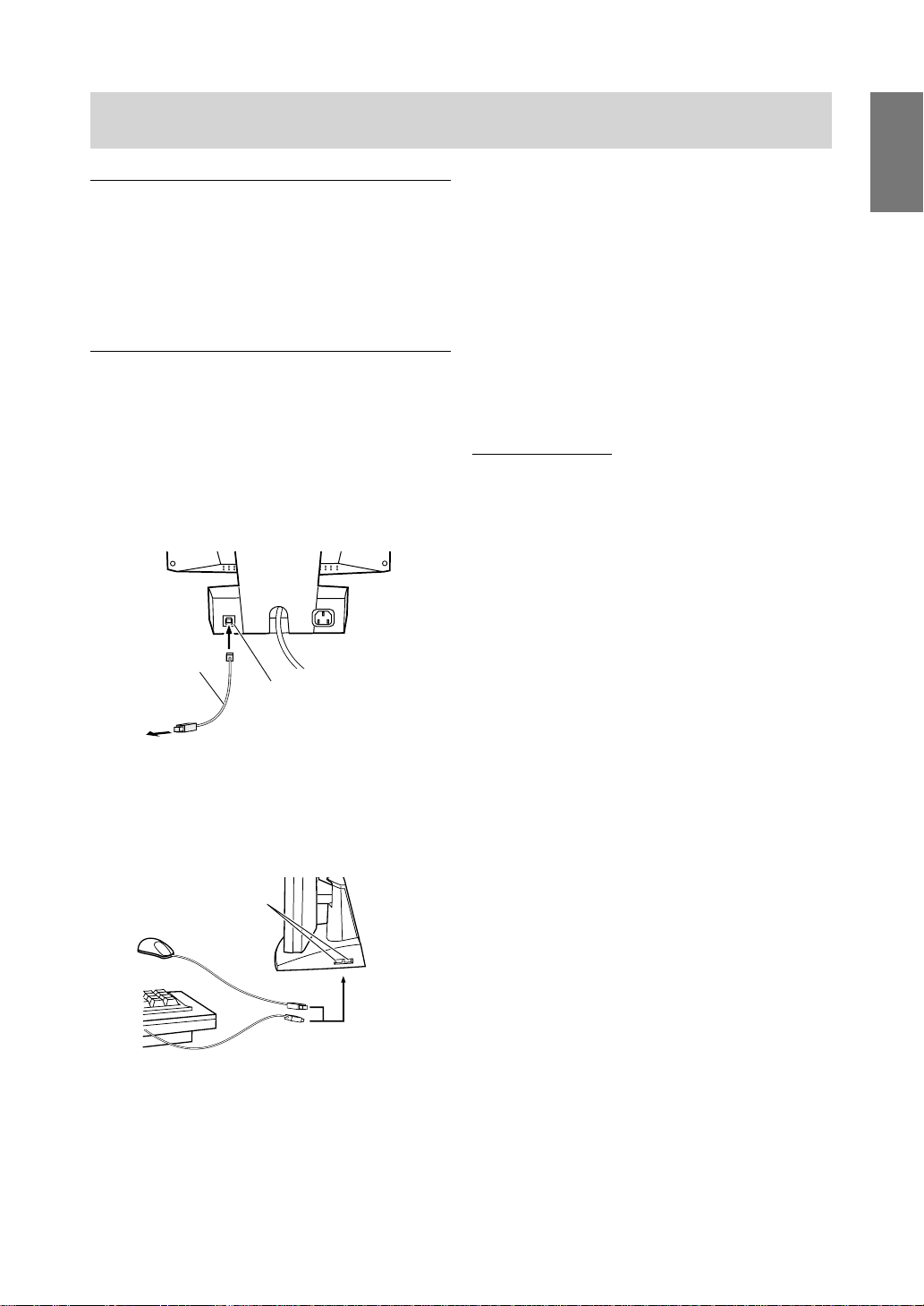
Connecting a USB device
If your computer or computer's OS is USB compatible, the monitor can be connected to a USB device .
1. Plug one end of the USB cable (provided) into
the monitor's USB upstream port.
2. Connect the other end of the USB cable into the
computer or the USB downstream port.
USB cable
(provided)
USB upstream port
Notes:
• Please use a USB cable that has a length of less
than 3 metres.
• Before connecting, ensure that the shape of the
USB cable connector is correct.
• For information regarding the USB function (such
as set-up) please refer to the operation manual of
the computer to be connected.
• Some computers, OS and other devices may not
be able to be activated. To ascertain a certain
device's USB compatibility, please contact the
manufacturer of the de vice.
USB specifications
Standard: Based on USB standard
(Rev. 1.1), b us-po w ered hub
Downstream port
power supply: 100 mA per port maximum
English
To the computer or another USB
hub’s downstream port
3. Plug the USB device into the monitor’s USB
downstream port.
USB downstream port
15
Page 16
Adjusting the screen display
If necessary , the screen can be adjusted as follows.
Automatic screen adjustment (right column)
The clock, phase, H-POS (horizontal positioning)
and V-POS (vertical positioning) functions can be
adjusted automatically .
Adjustment of backlight (p.17)
Brightness of backlight can be adjusted.
Manual adjustment (p. 18)
Fine adjustments can be made using the On Screen
Display (OSD) Menu.
Note:
• All adjustments will be saved e ven after turning
the power off.
All Reset MENU
All adjustment values can be returned to their
original ex-factory values in one command.
1. Press the power button to turn off the monitor
power.
2. Press the MENU button and the SELECT button
simultaneously, and while doing this press the
power button (i.e. turn the power on). When
[ALL RESET] appears on the screen, the reset is
complete.
Notes:
• While ALL RESET is displayed, the control
buttons do not function.
• It is not possible to reset values when the
adjustment lock is in place. Remove the
adjustment lock before attempting to operate
control buttons.
Adjustment lock function
By disabling the control buttons (i.e. setting the lock)
any attempted changes to adjusted values will be
voided.
1. Press the power button to turn off the monitor
power.
2. While pressing the MENU button, press the
power button (i.e. turn the power on).
When the menu is unlocked:
[ADJUSTMENT LOCKED] will appear on the
screen, and the lock will be set.
When the menu is locked:
[ADJUSTMENT UNLOCKED] will appear on the
screen, and the lock will be removed.
Note:
• When the lock is in place, all buttons other than
the power button are disabled.
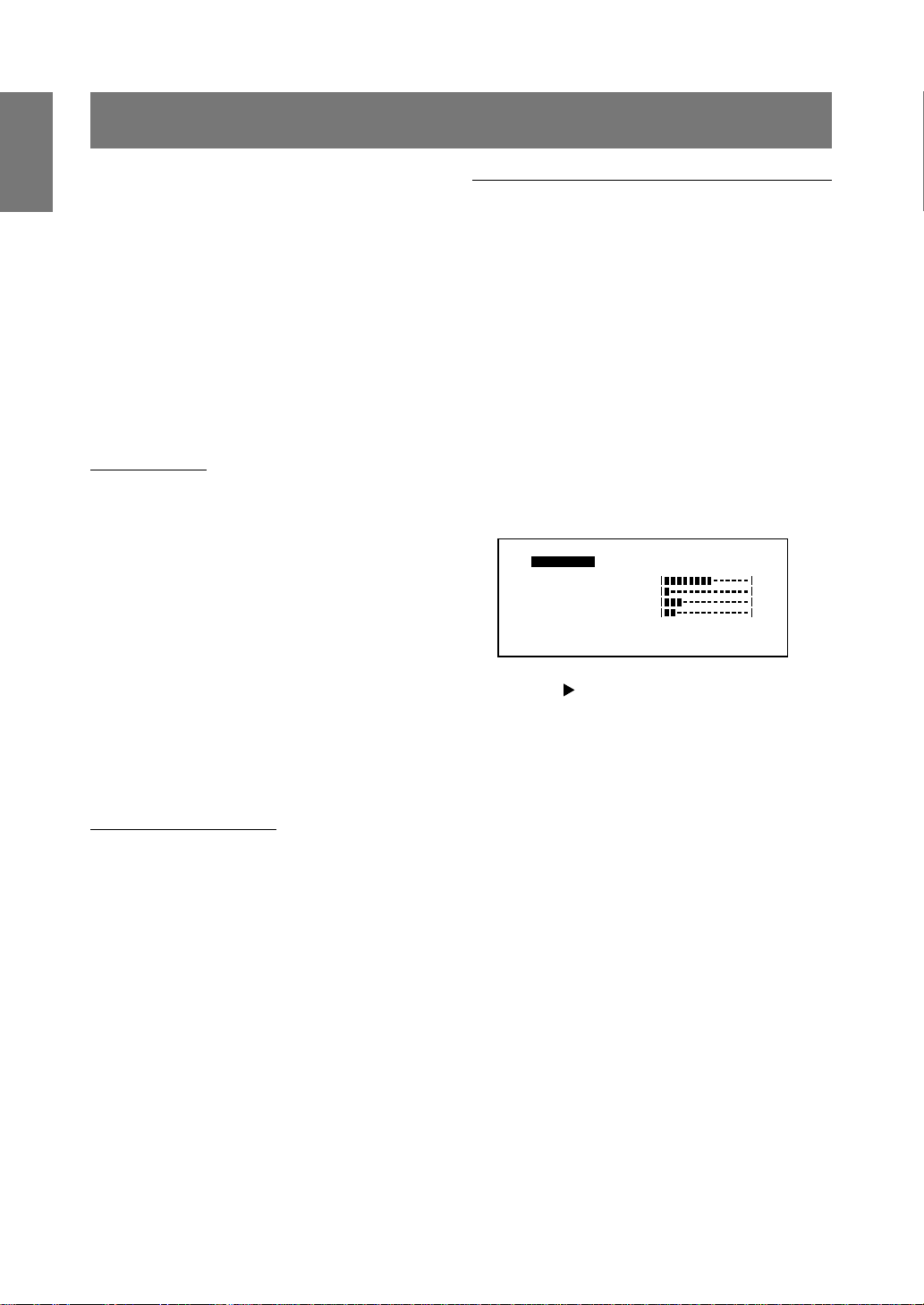
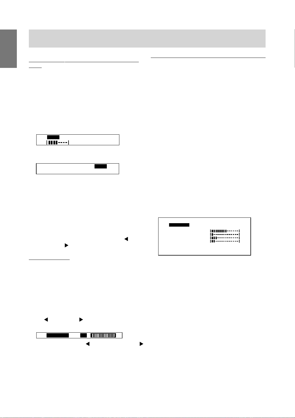
Automatic screen adjustment
Options in MENU 1 (ADJUSTMENT) can be adjusted automatically (Clock, Phase, H-POS, V-POS).
Note:
• When setting up this monitor for the first time or
after having changed an aspect of the current
system, perform an automatic screen adjustment
before use.
1. First display an image that makes the entire
screen very bright. If y ou are using Windows, you
can use the Adjustment Pattern on the
accompanying Monitor Settings Adjustment Disk
(p. 17).
2. Press the MENU button.
The ADJUSTMENT Menu will be displayed.
ACCD
[
LOO
H
H
V
0x
12
3. Press the button.
The screen will become dark and [ADJUSTING]
will be displayed. After a few seconds the
ADJUSTMENT Menu will return. (The automatic
adjustment is now complete.)
4. Press the MENU button four times to mak e the
Adjustment (OSD) Menu disappear.
Notes:
1. In most cases automatic adjustment is sufficient.
2. If necessary due to any of the following, manual
adjustments (p. 18) can be performed after the
automatic adjustment.
• When further fine adjustment is needed.
• When [OUT OF ADJUST] is displayed.
(When the screen displays an entirely dark
image, the automatic screen adjustment may
be disabled. When making an automatic
adjustment, be sure to either use the
Adjustment Pattern or try displaying an image
that makes the entire screen very bright.)
3. For LL-T1511A, pushing the BRIGHT button can
also make the Adjustment (OSD) Menu
disappear.
E
J
STTT
U
AA
LMMN
U
K
A
E
S
-
PPS
OPS4H6708
:k:4Hz
6
N
1
4
0
60
0 5
A
O
U
0
5
HV
z
8
]
16
Page 17
Adjusting the screen display
Opening the Adjustment Pattern (for Windows)
If you are using Windo ws , you can use the Adjustment Pattern on the accompanying Monitor Settings
Adjustment Disk.
This explanation is for Windows 95/98/Me/2000, and
assumes that the floppy disk drive is "A drive".
1. Place the Monitor Settings Adjustment Disk
(provided) into the computer’s A driv e .
2. Open [My Computer] and select [3 ½ Floppy
(A:)]. If using Windows 3.1, open [File Manager]
and choose "A drive".
3. Double click on [Adj_uty.exe] to run the
Adjustment Program. The Adjustment Pattern will
appear.
Adjustment pattern
Notes:
• After completing the adjustments, press the
computer’s [Esc] key to exit the Adjustment
Program.
• If the floppy disk drive of y our computer is not
"A drive", please read the below substituting the
floppy disk drive you are using in place of
"A drive" or "A".
• If your computer’s display mode is set to 65K
colors, you may see the different color levels in
each color pattern or the gray scale may look
colored. (This is due to the specification of the
input signal and is not a malfunction.)
Adjusting the backlight
Adjusting the backlight brightness
For LL-T1511A
Adjustments can be made in the following ways:
• Automatic adjustment based on the brightness of
the surrounding environment
• Switching between pre-set brightness modes
• Fine adjustment
For LL-T1501A
Adjustments can be made in the following way:
• Fine adjustment
Adjusting the backlight according to
surroundings (LL-T1511A only.)
The backlight brightness can be set to change
automatically for use in different surroundings .
Carry out the commands without the On Screen
Display (OSD) Menu displa yed. If the OSD Menu is
displayed, press the BRIGHT button. (You can also
make it disappear by pressing the MENU b utton a
number of times.)
1. Without the OSD Menu being displayed, push the
BRIGHT button.
2. Confirm that [AUTO] is selected.
If [AUTO] is not selected, press the BRIGHT
button a number of times until [AUTO] is
selected.
AUTO LOW MID HIGH
[]
You can also change the brightness of a
backlight that has been set according to the
current surroundings. (But from no w, the
backlight will adjust automatically using the
current backlight brightness as the base
standard.)
button (lighter)
button (darker)
3. Press the MENU button.
The OSD will disappear.
+–
English
If the brightness of the surroundings changes:
If the surroundings become brighter, the backlight
will become brighter.
If the surroundings become darker, the bac klight will
become darker .
Notes:
• The OSD Menu automatically disappears sev eral
seconds after the last command.
• The extent of change in brightness depends on
the brightness of the surrounding environment.
• Do not place anything in front of the brightness
sensor.
17
Page 18
Adjusting the screen display
Easy steps to changing brightness (LL-T1511A
only.)
The brightness can be changed to any one of three
settings.
Manual screen adjustment
Fine adjustments can be made using On Screen
Display (OSD) Menu provided.
Carry out the commands without the On Screen
Display (OSD) Menu displa yed. If the OSD Menu is
MENU 1: ADJUSTMENT
displayed, press the BRIGHT b utton and begin when
it has disappeared. (You can also make it disappear
by pressing the MENU button se veral times.)
MENU 2: GAIN CONTROL
1. Without the OSD Menu being displayed, push the
BRIGHT button.
AUTO LOW MID HIGH
[]
+–
MENU 3: WHITE BALANCE
MENU 4: MODE SELECT
2. Press the BRIGHT button seve ral times to
choose the brightness.
AUTO LOW MID HIGH
[]
3. Press the MENU button.
The OSD will disappear.
Notes:
• The OSD Menu automatically disappears sever al
seconds after the last command.
• If [AUTO] is selected, the backlight brightness
changes automatically for use in different
surroundings.
• After selecting the brightness (LOW, MID, HIGH),
fine adjustments can be made using the
button or the button.
Fine adjustments
Carry out the command when the Adjustment (OSD)
Menu is not displayed.
If the OSD Menu is displayed, press the MENU
button (sev er al times may be required) and carry out
1. Display an image that makes the entire screen
very bright. If using Windows, you can open and
use the Adjustment Pattern on the accompanying
Monitor Settings Adjustment Disk. (p. 17)
2. Press the MENU button.
ACCD
J
[
LOO
H
-
H
V
0x
12
:k:4Hz
The ADJUSTMENT Menu will be displayed. At
this point relevant men u options can be adjusted.
Each time the MENU button is pressed, the next
menu is selected. (MENU 1 → 2 → 3 → 4 →
OSD Menu disappears)
the command once the OSD Menu has disappeared.
(For LL-T1511A, the BRIGHT button can be used to
make the menu disappear .)
Notes:
1. The OSD Menu automatically disappears
approximately 15 seconds after the last
1. Without the OSD Menu being displayed, press
button or the button. The BRIGHT bar
the
will appear at the bottom section of the screen.
[]
BRIGHT 31
2. Adjust by pressing the button (darker) or the
button (lighter).
3. Press the MENU button.
The BRIGHT button will disappear .
command.
2. This explanation is based on using the
Adjustment Pattern (for Windo ws) to mak e
adjustments.
3. Press the BRIGHT button to make the OSD
Menu disappear.
4. For LL-T1511A, pushing the BRIGHT button can
also make the Adjustment (OSD) Menu
disappear.
E
N
STTT
U
AA
LMMN
U
K
A
E
S
PPS
OPS4H6708
6
Clock, Phase, H-POS (horizontal
positioning) and V-POS (vertical
positioning)
BLACK LEVEL, CONTRAST,
DISPLAY COLORS
WHITE BALANCE (color tone)
OSD H-POSITION (OSD
horizontal position), OSD
V -POSITION (OSD vertical
position), 400LINES (resolution),
SCALING (level of scaling)
]
1
4
0
60
0 5
A
O
U
0
5
HV
z
8
Note:
• The BRIGHT bar automatically disappears
several seconds after the last command.
18
Page 19
Adjusting the screen display
MENU 1: ADJUSTMENT
STTT
U
ACCD
[
LOO
H
H
-
V
12
0x
:k:4Hz
J
A
PPS
6
U
AA
K
S
E
OPS-
4H6708
N
E
LMMN
4
0
1
5
60
0
0 5
HV
U
A
O
8
z
]
MANUAL: Individual menu options are manually
adjusted.
AU TO: Every menu option is automatically
adjusted
Notes:
• Press the
button to select A UTO.
• To choose a menu option: SELECT button
• To go to MENU 2: MENU button
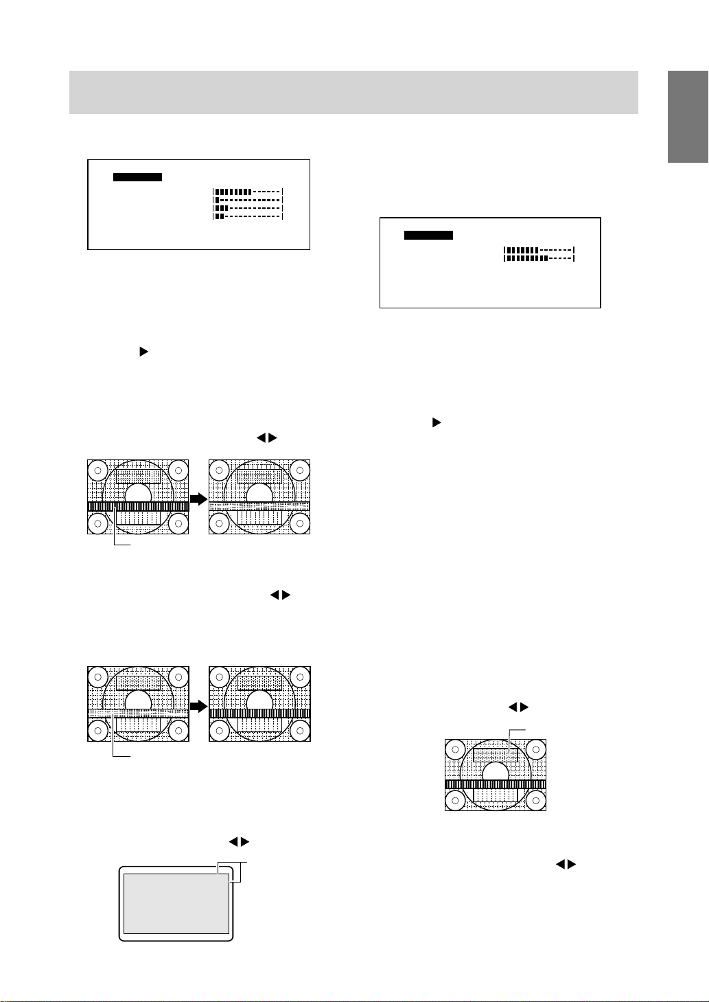
CLOCK
The figure below demonstrates how to adjust so that
vertical flicker noise is not emitted. (
Ver tical flicker noise
buttons)
PHASE
The figure below demonstrates how to adjust so that
horizontal flicker noise is not emitted. (
buttons)
Note:
• Adjustments to PHASE should be made only
after CLOCK has been correctly set.
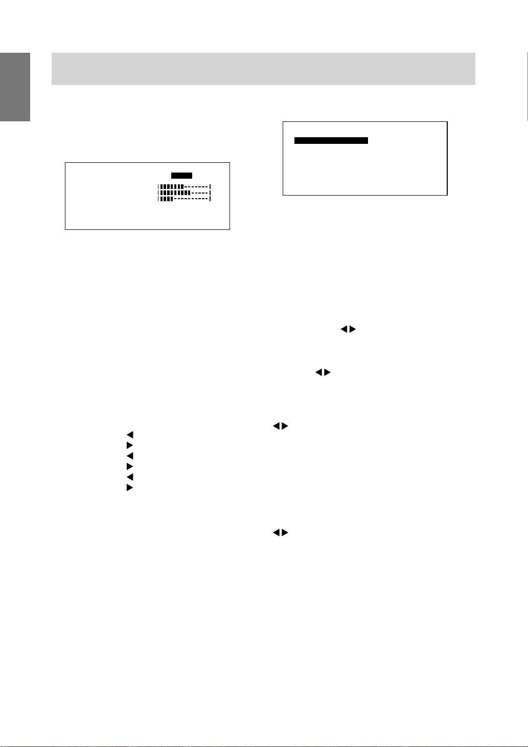
MENU 2: GAIN CONTROL
English
BLACK LEVEL and CONTRAST are optimized
before shipment, but depending on the type of
computer being used, further adjustment may be
necessary.
GA ILMONT
CROL
N
[]
BLACK LEVEL
CONTRAST
DISPLAY COLORS
12
N
AA A
U U
4678
0x
3
4
HV60:Hz 8Hzk:4
0
0
OT
620K 16M
MANUAL: Individual menu options are manually
adjusted.
AU TO: Every menu option is automatically
adjusted using the Auto Gain Control*
function,
Notes:
• Press the
button to select A UTO.
• To choose a menu option: SELECT button
• To go to MENU 3: MENU button
* Auto Gain Control function
• The Auto Gain Control adjusts contrast and b lac k
level based on the brightest color of the image
displayed. If you are not using the Adjustment
Pattern it is necessary to have an area of 5 mm x
5 mm of white displayed, and if not adjustments
may not be possible . (In such case, [OUT OF
ADJUST] will appear and setting values remain
unchanged.)
• To perform the Auto Gain Control function, first
go to MENU 3 and set [WHITE BALANCE] to
something other than [USER]. If [USER] is set,
Auto Gain Control will be disabled.
Horizontal flicker noise
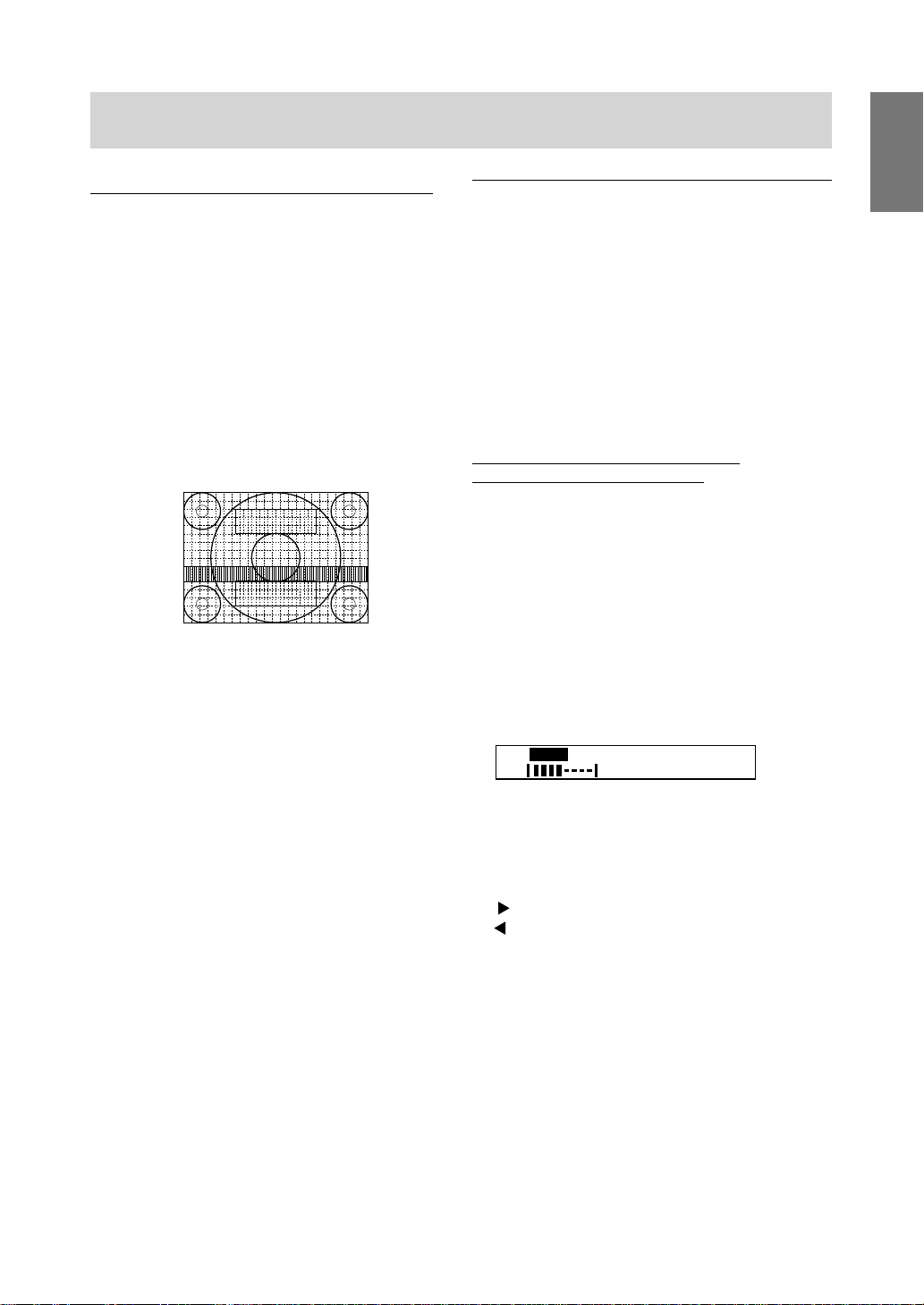
H-POS (horizontal positioning) and V-POS
(vertical positioning)
To center the screen image within the boundaries of
the screen, adjust the left-right (H-POS) values and
the up-down (V-POS) values. (
Adjustment
Pattern
buttons)
Screen frame
BLACK LEVEL
Total screen brightness can be adjusted while
watching the color pattern. (
buttons)
Color pattern
CONTRAST
While watching the color pattern, adjustments can be
made so that all graduations appear . (
buttons)
DISPLAY COLORS
Maximum display colors can be set.
260K (260,000) and 16M (16.19 million)
19
Page 20
Adjusting the screen display
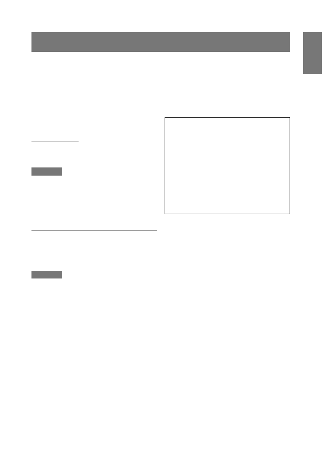
MENU 3: WHITE BALANCE
MENU 4: MODE SELECT
WHITE BALANCE (color tone) can be adjusted as
E
necessary. (As adjustments are made before shipment, there is no real necessity for further alteration.)
WH I
TEA
[]
OR
CBO
LM
R-CONTRAST
G-CONTRAST
B-CONTRAST
124 6780x
NE
L
A
C
.
.
W
D
S
AT
U ESR
340
0
20
HV60:Hz 8Hzk:4
M OO0D
[]
H-SO
V-
SD
LS
0
SCAL I NG
124 6780x
Notes:
• Depending on the resolution of the input signal,
even if men u options can be selected, the display
Notes:
• On settings other than [STD] not all graduations
can be displayed. To display all graduations, set
to STD.
• Selecting USER will display the setting values for
may not change.
• To choose a menu option:
SELECT button
• When adjustment complete:
MENU button
[R-CONTRAST], [G-CONTRAST] and
[B-CONTRAST], in order to make fine
adjustments.
• To choose a menu option: SELECT button
OSD H-POSITION (OSD horizontal position)
The position of the OSD display can be mov ed to
the left and right. (
• To go to MENU 4: MENU button
OSD V-POSITION (OSD vertical position)
COOL . . . Color tone bluer than standard
• . . . . . . Color tone slightly bluer than standard
The position of the OSD display can be mov ed up
and down. (
STD . . . . . Color tone standard setting
• . . . . . . Color tone slightly redder than standard
WARM. . . Color tone redder than standard
400 LINES (degree of resolution)
You can specify the horizontal resolution of a
400-line screen when using US text, etc.
USER
R-CONTRAST. . .
G-CONTRAST . .
B-CONTRAST. . .
button for blue-green
button for red
button for purple
button for green
button for y ello w
button for blue
buttons)
(
640 640 X 400 dot mode
720 720 X 400 dot mode (US text etc.)
Note:
• As the resolution input for other than 400 lines is
done automatically, there is no need to set it.
SLETCE
POD
T4IS
OPTIS
NI
E
buttons)
buttons)
NOI
NOI
HV60:Hz 8Hzk:4
046027
GIHOLW H
SCALING (Level of scaling)
The sharpness of the image can be adjusted.
buttons)
(
Note:
• Display modes of 1024 X 768 pixels cannot be
changed.
20
Page 21
Monitor care and repair
Monitor care
Always remove the plug from the AC outlet when
cleaning the monitor.
Cabinet and control panel section
Use a soft dry cloth to lightly wipe away any grime
from the cabinet and control panel.
If very dirty, apply neutral detergent to a dampened
soft cloth, wring it out well and wipe away grime.
LCD panel section
Use a soft dry cloth to lightly wipe away dirt and dust
from the surface of the LCD panel. (A soft cloth such
as gauze or that used for lens cleaning is suitable .)
CAUTION!
• Never use thinner, benzine, alcohol, glass
cleaner, etc , as this could lead to color change or
change in shape.
• Never scratch the monitor with an ything hard or
apply strong pressure as this could leave marks
or result in malfunction.
Storage
Troubleshooting
If you think the monitor may be faulty , please check
the following points bef ore taking it to be repaired.
If afterwards it still does not work, please contact the
shop where you purchased the monitor or your
nearest Sharp authorized Service Center.
The monitor’s florescent tubes ha v e a limited life
span.
• If the screen darkens, persistently flickers or
does not light up, it ma y be necessary to
replace the florescent tube unit. Please
inquire at the shop where you purchased the
monitor or your nearest Sharp authorized
Service Center. (Never attempt this
replacement on your own.)
• In the initial period of use, due to the
characteristics of florescent tubes the screen
may flick er. (This is not a malfunction.)
Should this happen, check by first turning off
the power , then turning it on again.
No image appears on the monitor (Po w er LED is not
lit)
• Is the power cord connected properly? (p. 12)
English
If the monitor will not be used for a long period of
time, be sure to remove the pow er plug from the AC
outlet.
CAUTION!
Do not leave the monitor in contact with rubber or
plastic items for long periods of time as this could
lead to color change or change in shape.
No image appears on the monitor (Po w er LED is lit)
• Is the computer connected properly? (p. 12)
• Is the computer turned on?
• Does the computer’s signal timing correspond to
monitor specifications? (p.23)
• Is the computer in power-saving mode?
Control buttons do not work
• Is the adjustment lock on? (p. 16)
Only VGA image is displayed
• Does the Windows display timing setting meet
monitor specifications? Refer to the monitor
signal timings (p. 23) and set to appropriate
timing.
The image appears distorted
• Does the computer’s signal timing correspond to
monitor specifications? (p.23)
• Perf orm automatic adjustment. (p. 16)
21
Page 22
Specifications
Product specifications
Item Specification
Name LL-T1511A
LCD display 38 cm (15 inches) Super-V and
Anti Glare Low Reflection
TFT LCD module
Dot pitch 0.297(H) x 0.297(V) mm
Screen display size Horizontal 304.1 mm X Vertical 228.1 mm
Resolution (max.) XGA 1024 X 768 pixels
Displayab le colors 16.19 million colors (max.)
Video signal Analog RGB (0.7Vp-p/75Ω)
Sync signals H-Sync (TTL level: +/-), V-Sync (TTL level: +/-)
Input terminal 15 pin Mini D-sub connector
Plug & Play function VESA DDC1 / DDC2B
Pow er management VESA DPMS based
Temperature of operating
environment 5–35°C
Pow er supply 100-240V
Pow er consumption 23W max. (3W po wer-saving mode)
Dimensions (W x D x H) 362 mm x 185 mm x 343 mm
Weight Approx. 5.2 kg
LL-T1501A
38 cm (15 inches) TFT LCD module
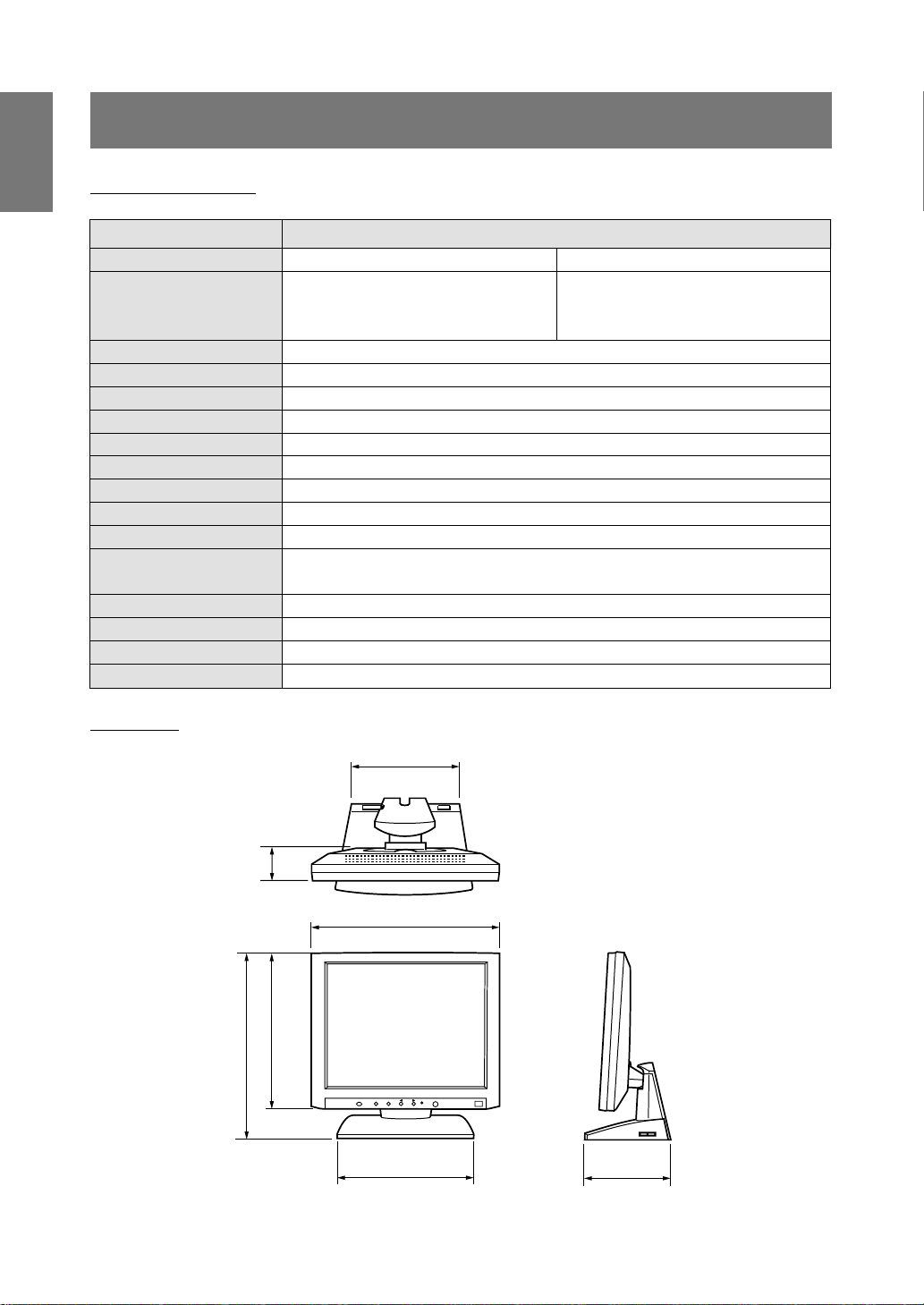
Dimensions (Units: mm)
343
174
50
362
292
240 185
22
Page 23
Specifications
Signal timings
Display mode Hsync (kHz) Vsync (Hz)
31.5kHz 60Hz 25.175MHz
640x480 37.9kHz 72Hz 31.5MHz
37.5kHz 75Hz 31.5MHz
VESA 35.1kHz 56Hz 36.0MHz
800x600
37.9kHz 60Hz 40.0MHz
48.1kHz 72Hz 50.0MHz
46.9kHz 75Hz 49.5MHz
48.4kHz 60Hz 65.0MHz
1024x768 56.5kHz 70Hz 75.0MHz
60.0kHz 75Hz 78.75MHz
US text 720x400 31.5kHz 70Hz 28.3MHz
Power Macintosh 640x480 35.0kHz 66.7Hz 30.5MHz
series 832x624 49.7kHz 74.6Hz 57.3MHz
1024x768 60.2kHz 75Hz 80.0MHz
Dot frequency
(MHz)
Notes:
• All are compliant only with non-interlace.
• Frequencies f or the Power Macintosh series are reference v alues .
• If the monitor is receiving timing signals that are not compatible, [OUT OF TIMING] will appear. Follow
your computer’s instruction manual to set the timing to be compatib le with the monitor.
• If the monitor is not receiving any signal (synch signal), [NO SIGNAL] will appear .
English
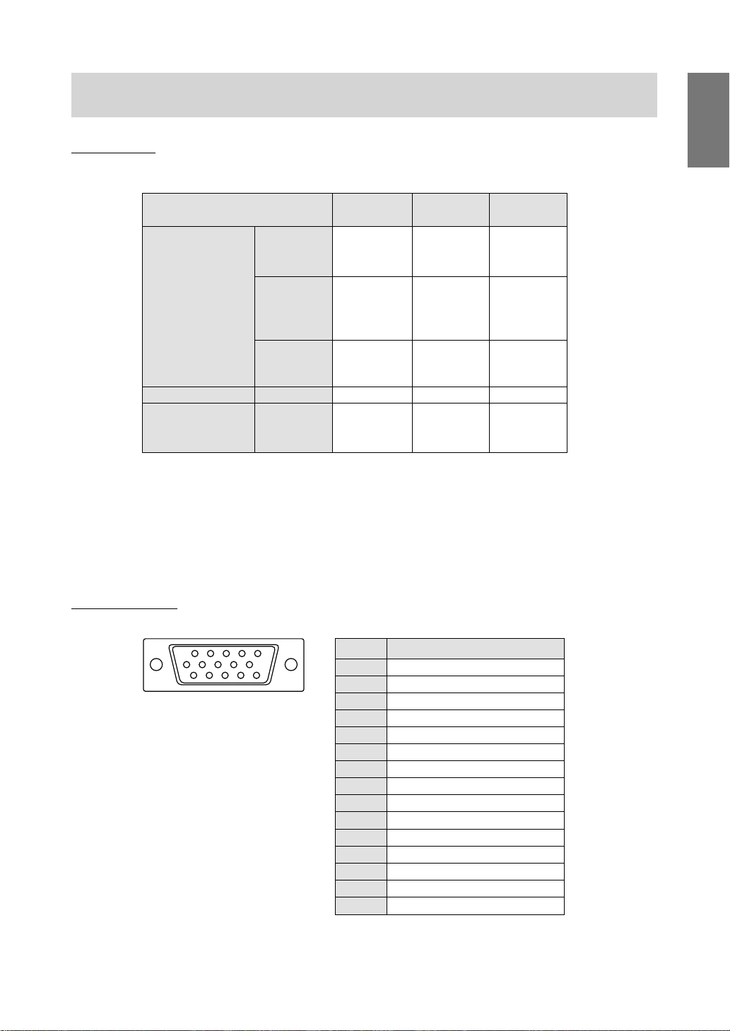
The connector pin
(Mini D-sub connector with 15 pins)
54321
10
9876
14131211
15
Number Function
1 Red video signal input
2 Green video signal input
3 Blue video signal input
4 N.C.
5 N.C.
6 For red video signal GND
7 For green video signal GND
8 For blue video signal GND
9 DDC + 5V
10 N.C.
11 GND
12 DDC data
13 For H-sync signal input
14 For V-sync signal input
15 DDC clock
23
Page 24
Specifications
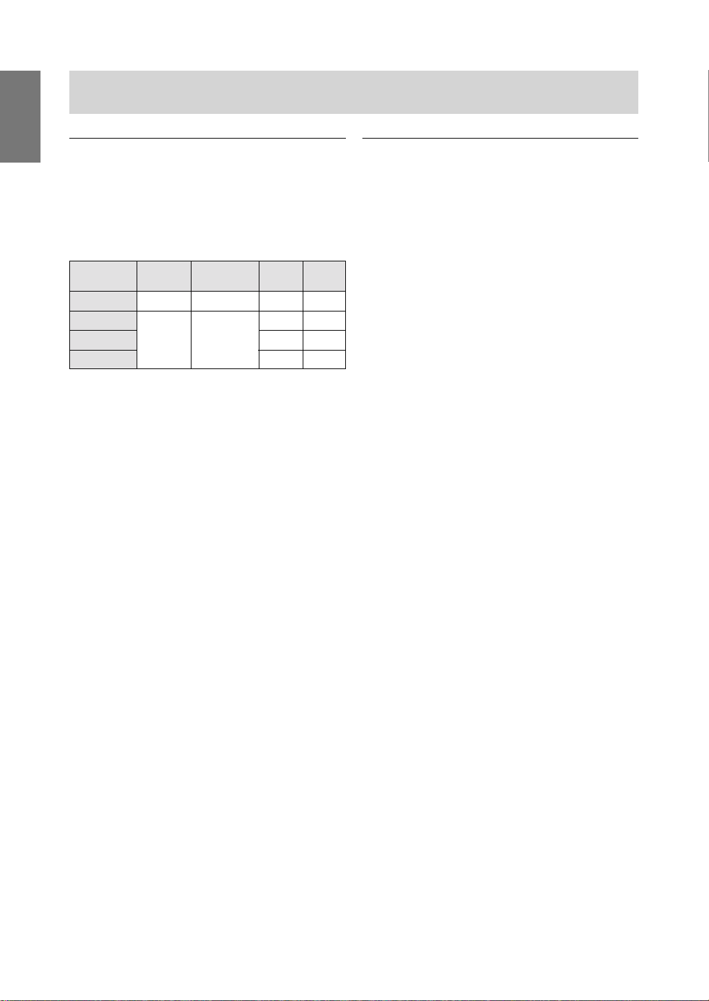
Power management
The monitor is based on VESA DPMS (Display
Pow er Management Signaling).
To activate the monitor's Power Management function, both the video card and the computer must
conform to the VESA DPMS standard.
DPMS mode Screen Power H-sync V-sync
consumption
ON Display on 23W Yes Yes
STANDBY No Yes
SUSPEND Display off 3W Yes No
OFF No No
DDC (Plug & Play)
This monitor supports the VESA DDC (Display Data
Channel) standard.
DDC is a signal standard for carrying out Plug &
Play functions on the monitor or PC. It transfers
information such as degree of resolution between
the monitor and PC. You can use this function if your
PC is DDC compliant and if it is set so that it can
detect the Plug & Play monitor .
There are many varieties of DDC due to the differences between systems. This monitor works with
DDC1 and DDC2B.
24
Page 25
Instructions for installing a VESA compliant arm
An arm or stand based on the VESA standard
(purchased separately) can be attached to the
monitor. To install the arm an AC adapter (purchased
separately) is required.
When choosing the arm to be installed take note of
the following points.
• The arm should be compatible with the VESA
standard, and there must be a gap of at least
75 mm x 75 mm between the screw holes on the
section to be attached.
• The arm must not fall off or break off after being
attached to the monitor.
If an arm is attached, a USB hub cannot be used.
(This is because the arm is installed inside the
monitor stand.)
Please be careful not to hurt your fingers or injure
yourself.
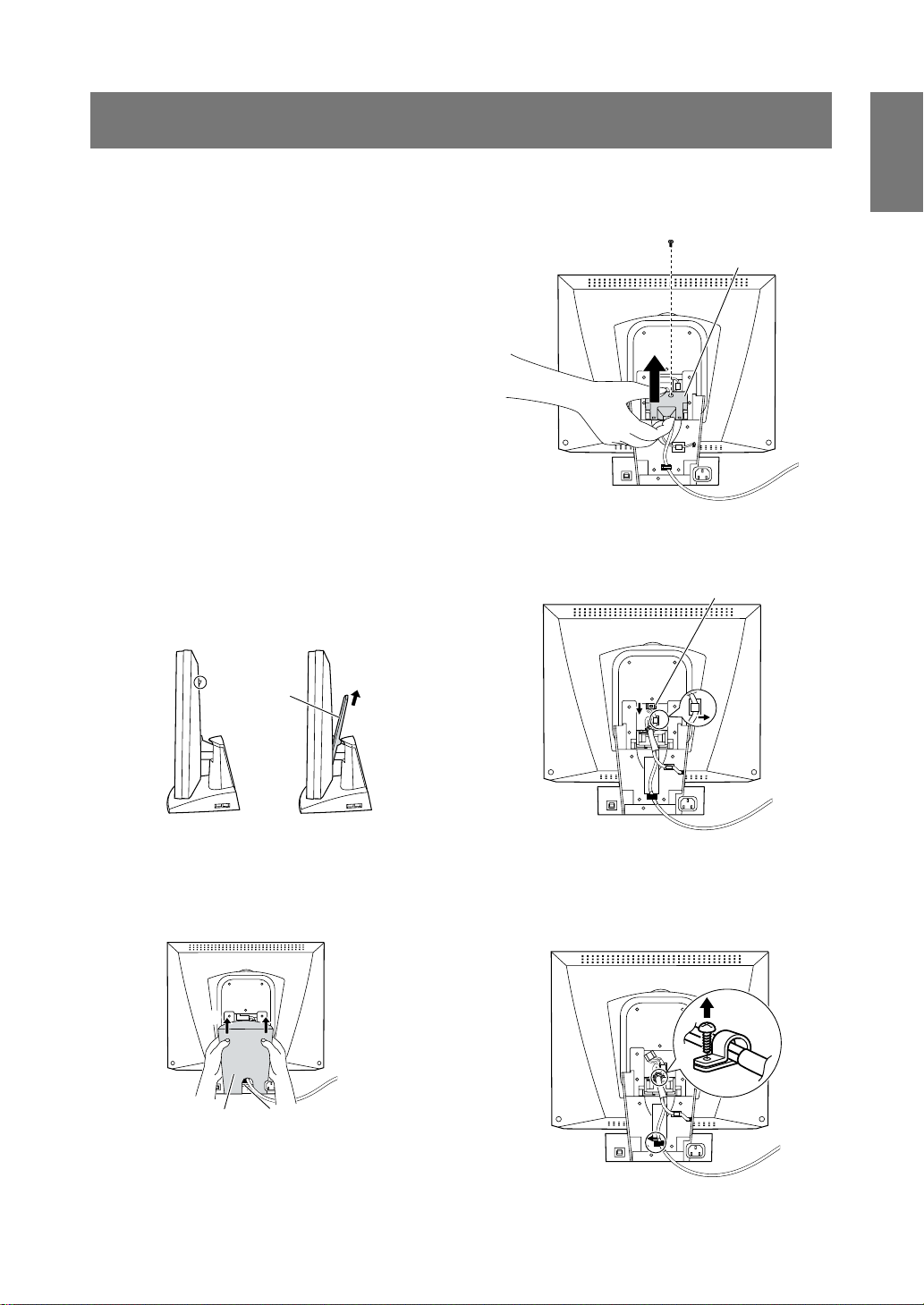
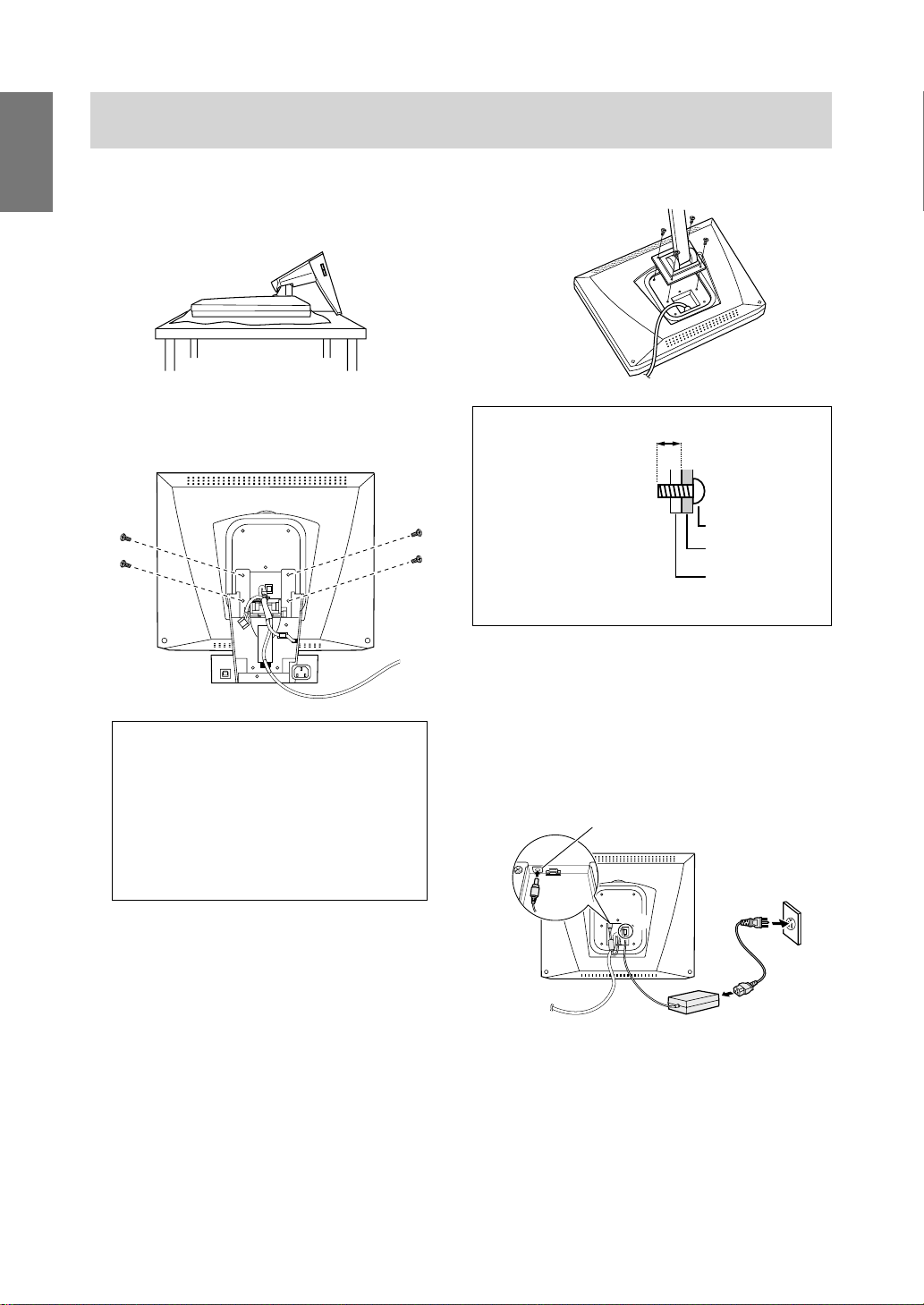
1. Turn off the main power switch and remov e the
power plug.
2. Remove the rear cov er.
Place your hand on the upper opening of the rear
cover 1 and pull it upward 2.
1
Rear cover
2
4. Remove the connector cove r.
Remove the screws and lift it upw ard.
Connector cover
5. Remove the DC connector 5.
6. Remove the DC cord from its hook 6.
DC connector
5
6
English
3. Remove the stand cov er.
Pull the stand cover upward to remove it 3.
If removal is difficult, place a finger inside the
lower opening 4 and lift it.
3
Stand cover
4
7. Remove the screws fixing the connector holder
and remove the connector holder 7.
8. Remove the signal cable from the cord holder
inside the stand 8.
7
8
25
Page 26
Instructions for installing a VESA compliant arm
9. Being careful not to damage the monitor, spread
out a soft cloth and lay the monitor on it displayside down.
10.Remove the four screws and then remove the
stand from the monitor.
Information
The stand is specially made for use with this
monitor. Once having removed the stand, never
attempt to attach it to another device.
Once having removed the screws, store them
together with the stand and if the stand is ever
re-attached be sure to use the original screws.
Using different screws could lead to malfunction.
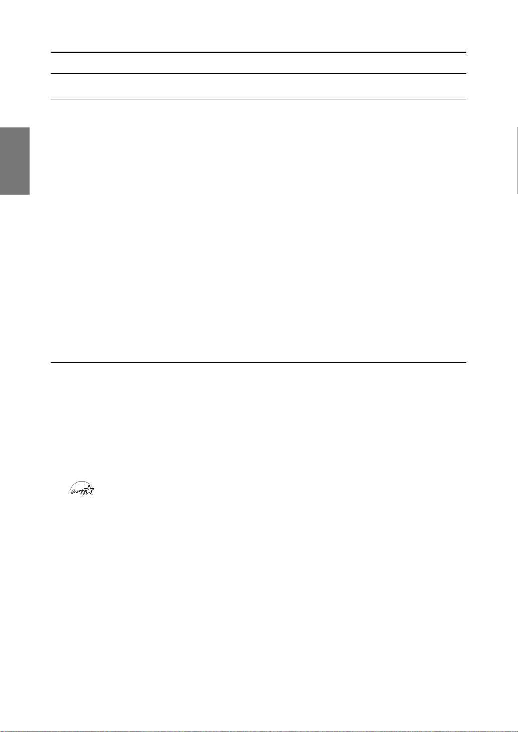
11.Attach the arm to the monitor with four screws.
Information
The screws used to
attach the arm should be
M4 screws with a length
of 4 ~ 6 mm protruding
from the surface to be
attached. Using any
other kind of screw may
lead to the monitor
falling off or damage to
the internal part of the
monitor.
4 ~ 6 mm
Screw used to
attach arm
Arm
Part of monitor
to which arm is
attached
12.Connect the AC adapter (purchased separately).
Connect the AC adapter's DC plug to the AC
adapter's connection terminal 9, and place the
cord inside the cord hook 0.
Coonect the power cord to the AC adapter q,
and connect the AC plug to the AC outlet w.
AC adapter connection terminal
9
0
w
26
q
Page 27

Inhaltsverzeichnis
Hinweis für Benutzer in den USA . . . . . . . . . . . . . . . . . . . . . . . . . . . . . . . . . . . . . . . . . . . . . . . . . . . . . . 28
TCO'99. . . . . . . . . . . . . . . . . . . . . . . . . . . . . . . . . . . . . . . . . . . . . . . . . . . . . . . . . . . . . . . . . . . . . . . . . . 29
Hinweis für Benutzer in Europa . . . . . . . . . . . . . . . . . . . . . . . . . . . . . . . . . . . . . . . . . . . . . . . . . . . . . . . 31
Hinweis für Benutzer in GB . . . . . . . . . . . . . . . . . . . . . . . . . . . . . . . . . . . . . . . . . . . . . . . . . . . . . . . . . . 32
Hinweis für Benutzer in Australien . . . . . . . . . . . . . . . . . . . . . . . . . . . . . . . . . . . . . . . . . . . . . . . . . . . . . 32
Tips und Sicherheitsvorkehrungen. . . . . . . . . . . . . . . . . . . . . . . . . . . . . . . . . . . . . . . . . . . . . . . . . . . . . 33
Produktbeschreibung . . . . . . . . . . . . . . . . . . . . . . . . . . . . . . . . . . . . . . . . . . . . . . . . . . . . . . . . . . . . . . . 34
Anschließen des Monitors und Ein- und Ausschalten des Monitors. . . . . . . . . . . . . . . . . . . . . . . . . . . . 36
Verbinden des Monitors mit einem Computer (PC usw.) . . . . . . . . . . . . . . . . . . . . . . . . . . . . . . . . . 36
Anschließen des Monitors an eine Stromquelle . . . . . . . . . . . . . . . . . . . . . . . . . . . . . . . . . . . . . . . 36
Einschalten des Monitors . . . . . . . . . . . . . . . . . . . . . . . . . . . . . . . . . . . . . . . . . . . . . . . . . . . . . . . . 36
Ausschalten des Monitors . . . . . . . . . . . . . . . . . . . . . . . . . . . . . . . . . . . . . . . . . . . . . . . . . . . . . . . . 39
Anschließen eines USB-Geräts . . . . . . . . . . . . . . . . . . . . . . . . . . . . . . . . . . . . . . . . . . . . . . . . . . . 39
Einstellen der Bildschirmanzeige . . . . . . . . . . . . . . . . . . . . . . . . . . . . . . . . . . . . . . . . . . . . . . . . . . . . . . 40
Automatische Bildschirmeinstellung . . . . . . . . . . . . . . . . . . . . . . . . . . . . . . . . . . . . . . . . . . . . . . . . 40
Einstellen der Hintergrundbeleuchtung . . . . . . . . . . . . . . . . . . . . . . . . . . . . . . . . . . . . . . . . . . . . . . 41
Manuelle Bildschirmeinstellung. . . . . . . . . . . . . . . . . . . . . . . . . . . . . . . . . . . . . . . . . . . . . . . . . . . . 42
Pflege des Monitors und Reparaturen . . . . . . . . . . . . . . . . . . . . . . . . . . . . . . . . . . . . . . . . . . . . . . . . . . 45
Pflege des Monitors . . . . . . . . . . . . . . . . . . . . . . . . . . . . . . . . . . . . . . . . . . . . . . . . . . . . . . . . . . . . 45
Lagerung . . . . . . . . . . . . . . . . . . . . . . . . . . . . . . . . . . . . . . . . . . . . . . . . . . . . . . . . . . . . . . . . . . . . . 45
Fehlersuche . . . . . . . . . . . . . . . . . . . . . . . . . . . . . . . . . . . . . . . . . . . . . . . . . . . . . . . . . . . . . . . . . . 45
Technische Daten. . . . . . . . . . . . . . . . . . . . . . . . . . . . . . . . . . . . . . . . . . . . . . . . . . . . . . . . . . . . . . . . . . 46
Anweisungen zum Installieren eines VESA-kompatiblen Arms . . . . . . . . . . . . . . . . . . . . . . . . . . . . . . . 49
GB
Deutsch
FIE
27
Page 28
Hinweis für Benutzer in den USA
FCC-Hinweis
ACHTUNG – Änderungen oder Modifikationen an diesem Gerät, die nicht ausdrücklich vom Hersteller
genehmigt wurden, können laut FCC-Richtlinie zum Erlöschen der Betriebsberechtigung führen.
Hinweis: Dieses Gerät wurde geprüft und entspricht den Grenzwerten für digitale Geräte der Klasse B
gemäß Teil 15 der FCC-Richtlinien.
Diese Grenzwerte dienen dem ausreichenden Schutz gegen Störungen bei einer Installation in
Wohnbereichen. Dieses Gerät erz eugt Funkfrequenzenergie , arbeitet damit und kann diese abstrahlen.
Falls bei der Installation die Anweisungen in der Anleitung k eine Beachtung finden, k önnen
schwerwiegende Störungen beim Funkverkehr hervorgerufen werden. Es kann jedoch keine Garantie
gegeben werden, daß in bestimmten Installationen nicht doch Störungen auftreten. Sollte das Ger ät
Störungen beim Radio- oder Fernsehempfang hervorrufen, die durch Ein- und Ausschalten des Gerätes
festgestellt werden können, sollte der Anw ender v ersuchen, die Störung durch eine der f olgenden
Maßnahmen zu beheben.
– Die Empfangsantenne neu ausrichten oder deren Standort ändern.
– Den Abstand zwischen dem Gerät und dem Empfänger vergrößern.
– Das Gerät an eine andere Steckdose anschließen, die nicht zum Stromkreis des Empfängers gehört.
– Den Händler oder einen erfahrenen Rundfunk-/Fernsehtechniker zu Rate ziehen.
Nur die mitgelieferten Kabel und das Netzkabel verwenden, um eine Einhaltung der FCC-Richtlinien für
Computer-Geräte der Klasse B sicherzustellen.
Konformitätserklärung
SHARP LCD -Farbmonitor LL-T1511A,LL-T1501A
Dieses Gerät entspricht Teil 15 der FCC-Richtlinien. Um dieses Gerät in Betrieb nehmen zu dürfen,
müssen folgende Bedingungen eingehalten werden: (1) Dieses Gerät darf keine Störungen hervorrufen,
und (2) dieses Gerät darf nicht anfällig für Störungen sein, darunter Störungen, die zu einer Verkleinerung
des Anzeigeformats führen können.
V erantwortlicher Hersteller: SHARP ELECTRONICS CORPORA TION
Sharp Plaza, Mahwah, New Jersey 07430
TEL :1-800-BE-SHARP
* Als ENERGY STAR-Partner bestätigt SHARP, daß dieses Produkt die Richtlinien des ENERGY STAR
für sparsamen Verbrauch einhält.
In diesem Produkt wird bleihaltiger Lötzinn und eine Leuchtstofflampe mit einem geringen
Quecksilberanteil verwendet. Die Entsorgung dieser Materialien unterliegt möglicherweise bestimmten
Umweltrichtlinien. Inf ormationen zur Entsorgung bzw. zum Recycling können von den örtlichen Behörden
oder von der Electronics Industries Alliance unter www .eiae .org angef ordert werden
28
Page 29

GB
Deutsch
Herzlichen Glückwunsch!
Sie haben gerade ein Gerät mit TCO‘99-Zulassung und entsprechender Kennzeichnung erworben! Damit
haben Sie sich für ein Produkt entschieden, das für professionelle Anwendungen konzipiert ist. Mit Ihrem
Kauf leisten Sie auch einen Beitrag zum Umweltschutz und zur W eiterentwic klung von umweltfreundlichen
Elektronikprodukten.
Warum verkaufen wir Computer mit Umweltkennzeichnung?
In vielen Ländern dient die Kennzeichnung mit Umweltzeichen als Anreiz für die F ertigung und Bereitstellung
umweltverträglicher Konsumgüter und Dienste. Das Hauptproblem im Zusammenhang mit Computern und
anderen elektronischen Geräten besteht darin, daß umweltschädliche Stoffe in den Produkten enthalten sind
und auch während der Fertigung eingesetzt werden. Da es bis jetzt noch nicht möglich ist, den Großteil der
elektronischen Geräte hinlänglich zu recyceln, gelangen fast alle dieser möglicherweise schädigenden
Substanzen früher oder später in den Naturkreislauf.
Weitere Eigenschaften eines Computers, beispiels weise sein Energieverbrauch, sind aus Sicht der Arbeitsumgebung (intern) und natürlichen Umgebung (extern) ebenfalls von Bedeutung. Da alle Verfahren zur
Stromerzeugung negative Auswirkungen auf die Umwelt haben (beispielsweise saurer Regen, klimabeeinflussende Emissionen, radioaktiver Abfall), k ommt es darauf an, möglichst Energie zu sparen. Elektronische Geräte in Büros sind oft durchgehend eingeschaltet und verbrauchen deshalb viel Strom.
Welche Bedeutung hat die Kennzeichn ung?
Dieses Produkt entspricht den Anforderungen der TCO‘99-Verordnung, die sich mit internationalen Kennzeichnungen und Umweltzeichen für PCs bef aßt. Die Kennzeichnungen wurden gemeinsam v on der TCO
(Schwedische Zentralorganisation für Angestellte und Beamte), Svenska Naturskyddsf oreningen (Schwedische Gesellschaft für Naturschutz) und Statens Energimyndighet (Schwedische Nationale Energiebehörde)
entwickelt.
Zulassungsanforderungen beschäftigen sich mit den unterschiedlichsten Belangen: Umwelt, Ergonomie,
Nutzbarkeit, Emission elektrischer und magnetischer Felder , Energie verbrauch und elektrische Sicherheit
sowie Brandschutz.
Die Umweltanforderungen beschränken u.a. das Vorkommen und die Verwendung von Schwermetallen,
brom- und chlorhaltigen Flammschutzmitteln, FCKW (Freon) und Chlorlösungsmitteln. Das Produkt muß
recyclingfähig sein, und der Hersteller muß einen Umweltplan ausgearbeitet haben, der in allen Ländern, in
denen das Unternehmen seine Betriebsstrategie realisiert, eingehalten werden muß.
Die Energieanforderungen beinhalten die Forderung, daß der Computer und/oder sein Anzeigegerät nach
einer bestimmten Zeit der Inaktivität die Leistungsaufnahme in einer oder mehreren Stufen verringern muß.
Die Reaktivierungszeit des Computers muß für den Benutzer in einem vernünftigen Rahmen liegen.
Gekennzeichnete Produkte müssen strenge Umweltanf orderungen einhalten, beispielsweise hinsichtlich der
V erringerung elektrischer und magnetischer Felder, physikalischer und visueller Ergonomie und guter
Nutzbarkeit.
Nachfolgend finden Sie eine kurze Zusammenf assung der Umweltanforderungen, die von diesem Produkt
eingehalten werden. Ein Dokument mit allen Umweltkriterien können Sie unter f olgender Adresse anf ordern:
FIE
29
Page 30

TCO Development
SE-114 94 Stockholm, Sweden
Fax: +46 8 782 92 07
Email (Internet): dev elopment@tco .se
Aktuelle Informationen zu Produkten mit TCO‘99-Zulassung und -K ennz eichnung erhalten Sie auch im
Internet unter folgender Adresse: http://www.tco-info .com/
Umweltanforderungen
Flammschutzmittel
Flammschutzmittel kommen in Platinen, Kabeln, Drähten, Verkleidungen und Gehäusen vor. Sie sollen die
Ausbreitung eines Brandes verhindern oder zumindest verz ögern. Bis zu 30 % der Kunststoffteile in einem
Computergehäuse können aus Flammschutzsubstanzen bestehen. Die meisten Flammschutzmittel enthalten Brom oder Chlorid und lassen sich in chemischer Hinsicht mit einer anderen Gruppe umweltschädigender Stoffe, den PCBs, in V erbindung bringen. Brom- und chlorhaltige Flammschutzmittel und die
PCBs stehen im Verdacht, schwere gesundheitliche Störungen hervorzurufen, darunter aufgrund des
bioakkumulativen* Prozesses reproduktiv e Schädigungen v on fischfressenden Vögeln und Säugetieren.
Flammschutzmittel wurden bereits im menschlichen Blut nachgewiesen. Forscher fürchten, daß es zu einer
Schädigung der Fötusentwicklung k ommen kann.
Die relevanten Anforderungen der TCO’99 verlangen, daß Kunststoffbauteile mit einem Gewicht von über
25 g keine Flammschutzmittel mit organisch gebundenem Brom oder Chlor enthalten dürf en.
Flammschutzmittel bei Platinen sind zulässig, da keine alternativen Lösungen zur Verfügung stehen.
Cadmium**
Cadmium kommt in Akkus und in den farberzeugenden Schichten bestimmter Computerbildschirme vor.
Cadmium schädigt das Nervensystem und ist in hoher Dosierung giftig. Die rele v ante TCO’99-Anforderung
verlangt, daß Batterien, die farberzeugenden Schichten von Anz eigebildschirmen und elektrische oder
elektronische Komponenten kein Cadmium enthalten dürf en.
Quecksilber**
Quecksilber kommt manchmal in Batterien, Relais und Schaltern vor. Es schädigt das Nervensystem und ist
in hoher Dosierung giftig. Die rele v ante TCO‘99-Anforderung verlangt, daß Batterien kein Quec ksilber
enthalten dürfen. Außerdem verlangt sie, daß Quecksilber weder in elektrischen noch elektronischen Komponenten vorkommen darf, die zu gekennzeichneten Einheiten gehören. Dabei gibt es jedoch eine A usnahme. Im A ugenblick ist der Einsatz von Quecksilber in der Hintergrundbeleuchtung von Flachbildschirmen
zulässig, da es derzeit noch keine wirtschaftliche Alternative gibt. Die TCO bemüht sich um eine Abschaffung dieser Ausnahme, sobald eine quecksilberfreie Alternative zur V erfügung steht.
FCKW (Freon)
Die relevante TCO‘99-Anforderung verlangt, daß weder FCKW noch HFCKW während der F ertigung und
beim Zusammenbau des Produkts verwendet werden darf. FCKW (Freon) wird manchmal zum Waschen von
Platinen eingesetzt. FCKW z erstört Ozon und schädigt dadurch die Ozonschicht in der Stratosphäre . Die
Folge sind höhere ultraviolette Strahlenbelastungen auf der Erde , w as beispiels w eise das Hautkrebsrisik o
(Malignes Melanom) erhöht.
Blei**
Blei findet man in Bildröhren, Anzeigebildschirmen, Lötverbindungen und Kondensatoren. Blei schädigt das
Nervensystem und führt in höherer Dosierung zu einer Bleivergiftung. Die relev ante TCO‘99-Anforderung
gestattet die Verwendung von Blei, da noch k eine Ersatzstoffe entwickelt wurden.
*
Bioakkumulativ definiert man als Substanzen, die sich in lebenden Organismen ansammeln.
**
Blei, Cadmium und Quecksilber sind bioakkumulative Schw ermetalle.
30
Page 31

Hinweis für Benutzer in Europa
This equipment complies with the requirements of Directives 89/336/EEC and 73/23/EEC as amended by
93/68/EEC.
Dieses Gerät entspricht den Anforderungen der EG-Richtlinien 89/336/EWG und 73/23/EWG mit
Änderung 93/68/EWG.
Ce matériel répond aux exigences contenues dans les directives 89/336/CEE et 73/23/CEE modifiées
par la directive 93/68/CEE.
Dit apparaat voldoet aan de eisen van de richtlijnen 89/336/EEG en 73/23/EEG, ge wijzigd door 93/68/
EEG.
Dette udstyr overholder kra v ene i direktiv nr. 89/336/EEC og 73/23/EEC med tillæg nr. 93/68/EEC.
Quest' apparecchio è conforme ai requisiti delle direttive 89/336/EEC e 73/23/EEC, come emendata dalla
direttiva 93/68/EEC.
Η εγκατασταση ανταποκρινεται στιζ απαιτησειζ των οδηγιων τηζ Ευρωπαïκηζ Ενωσηζ 89/336/ΕΟΚ κατ 73/23/ΕΟΚ,
óπωζ οι κανονισµοι αυτοι συµπληρωθηκαν απó την οδηγια 93/68/ΕΟΚ.
Este equipamento obedece às exigências das directivas 89/336/CEE e 73/23/CEE, na sua v ersão
corrigida pela directiva 93/68/CEE.
Este aparato satisface las e xigencias de las Directivas 89/336/CEE y 73/23/CEE, modificadas por medio
de la 93/68/CEE.
Denna utrustning uppfyller kraven enligt riktlinjerna 89/336/EEC och 73/23/EEC så som komplette ras av
93/68/EEC.
GB
Deutsch
FIE
Dette produktet oppfyller betingelsene i direktivene 89/336/EEC og 73/23/EEC i endringen 93/68/EEC.
Tämä laite täyttää direktiivien 89/336/EEC ja 73/23/EEC v aatimukset, joita on muutettu direktiivillä 93/68/
EEC.
CAUTION :
TO PREVENT ELECTRICAL SHOCK, DISCONNECT THE AC CORD BEFORE SER VICING.
CAUTION :
FOR A COMPLETE ELECTRICAL DISCONNECTION, PULL OUT THE MAIN PLUG.
VORSICHT :
UM DIE STROMZUFUHR VOLLSTÄNDIG ZU UNTERBRECHEN, DEN NETZSTECKER HERAUSZIEHEN
ENTFERNEN.
ATTENTION :
POUR UN ARRET TOTAL DU SYSTEMS, DECONNECTEZ LA PRISE DE COURANT SECTEUR.
VARNING :
FÖR TOTAL ELEKTRISK URKOPPLING, KOPPLA UR KONTAKTEN OCH.
PRECAUCION :
PARA UNA COMPLETA DESCONEXION ELECTRICA DESENCHUFE LA CLAVIJA DE LA RED.
31
Page 32

Hinweis für Benutzer in GB
FÜR KUNDEN IN GB
WICHTIG
Die Drähte in diesem Netzkabel sind nach folgendem Code farbig gekennzeichnet:
GRÜN/GELB : Masse
BLAU : Nulleiter
BRAUN : Stromführend
Da die Farben der Drähte im Netzkabel dieses Gerätes möglicherw eise nicht den
Farbk ennzeichn ungen der Anschlüsse in Ihrem Stec k er entsprechen, müssen Sie folgendermaßen
vorgehen. Der GRÜN/GELB gekennzeichnete Draht muß im Stecker mit dem Anschluß verbunden
werden, der mit dem Buchstaben EE oder mit der Sicherheitserdung gekennzeichnet ist oder grün
oder grün/gelb ist.
Der BLAUE Draht m uß mit dem Anschluß verbunden werden, der mit dem Buchstaben N gekennzeichnet oder schwarz ist.
Der BRAUNE Draht muß mit dem Anschluß verbunden werden, der mit dem Buchstaben L gekennzeichnet oder rot ist.
Ein ordnungsgemäßer Anschluß des Gerätes muß sichergestellt werden. Im Zweifelsfall wenden Sie
sich an einen Elektrofachmann.
“WARNUNG: DIESES GERÄT MUSS GEERDET WERDEN.”
Hinweis für Benutzer in Australien
Serviceanfragen
Wenden Sie sich an Ihren Händler , falls Reparaturen anfallen, oder setzen Sie sich mit Sharp
Corporation of Australia unter 1 300 13 50 22 in Verbindung, um die Adresse des nächstgelegenen
autorisierten Sharp-Kundendienstzentrums zu erfragen.
32
Page 33

Tips und Sicherheitsvorkehrungen
• Unter bestimmten Anzeigebedingungen können
kleine Flecken oder Punkte sichtbar sein. Dies ist
normal bei LCD-Monitoren und es handelt sich
um keine Funktionsstörung.
• Das LCD-Panel wurde unter Einsatz
hochentwickelter Technologie gefertigt. 99,99 %
der Bildpunkte werden einwandfrei angezeigt. Es
kann jedoch vorkommen, daß max. 0,01% der
Bildpunkte fehlen oder heller als normal angezeigt
werden.
• Die Bildschirmanzeige sollte nicht über lange
Zeiträume hinweg stehenbleiben, da dies einen
Einbrenneffekt zur Folge haben k önnte.
• Wenn die Helligkeit auf die Mindesteinstellung
gesetzt wird, ist der Bildschirm eventuell schlecht
lesbar.
• Die Qualität des Computersignals kann die
Anzeigequalität beeinträchtigen. Wir empf ehlen
den Einsatz eines Computers, der Videosignale
hoher Qualität aussenden kann.
• Der Monitor darf niemals mit harten
Gegenständen abgerieben oder berührt werden.
• Wir bitten um Ihr Verständnis, daß Sharp Corporation über die gesetzlich anerkannte
Leistungshaftung hinaus keine Haftung für Fehler
übernimmt, die sich aus der Verwendung durch
den Kunden oder einen Dritten ergeben, und
auch nicht für sonstige Funktionsstörungen oder
Schäden, die während der Verwendung am Gerät
entstehen.
• Eine Aktualisierung dieses Monitors und seines
Zubehörs ist vorbehalten.
und nicht in der Nähe von Heizungen oder an
anderen Stellen, an denen hohe Temperaturen
auftreten, da dies zu einer übermäßig starken
Erhitzung mit der Folge eines Brandes führen
könnte.
Das Netzkabel
• Beschädigen Sie das Netzkabel nicht, stellen Sie
keine schweren Gegenstände darauf , und überdehnen oder knicken Sie es nicht. Verwenden Sie
keine Verlängerungskabel. Ein beschädigtes
Kabel kann einen Brand oder Stromschlag
verursachen.
• Stecken Sie den Netzstecker direkt in die Netzsteckdose. Die Verwendung eines V erlängerungskabels kann aufgrund von Überhitzung zu einem
Brand führen.
Checkliste für Monitor und Zubehör
• Prüfen Sie den Kartoninhalt auf Vollständigkeit.
• LCD-Monitor (1)
• USB-Kabel (1)
• Monitor-Einstelldiskette für Windows (1)
• Bedienungsanleitung (1)
Hinweise:
• Bewahren Sie den Karton für einen eventuellen
Transport des Monitors auf.
• Die Urheberrechte am Programm auf der Monitor-Einstelldiskette sind Sharp Corporation
vorbehalten. Eine Reproduktion ist ohne Genehmigung nicht zulässig.
GB
Deutsch
FIE
Aufstellort
• V erwenden Sie den Monitor nicht an schlecht
belüfteten Orten mit hoher Staubentwicklung,
hoher Luftfeuchtigkeit oder an Orten, an denen
der Monitor mit Öl oder Dampf in Kontakt kommen könnte, da dies ein Brandrisiko birgt.
• Achten Sie darauf, daß der Monitor nicht mit
Wasser oder anderen Flüssigkeiten in Berührung
kommt. Achten Sie dar auf, daß keinerlei Gegenstände, beispielsweise Büroklammern oder
sonstige spitze Gegenstände, in den Monitor
gesteckt werden. Die Folge könnte ein Brand
oder Stromschlag sein.
• Stellen Sie den Monitor nicht auf wacklige Unterlagen oder auf unsichere Stellen. Setz en Sie den
Monitor keinen starken Stößen oder Erschütterungen aus. Wenn der Monitor herunterfällt oder
umkippt, könnte er Schaden nehmen.
• Stellen Sie den Monitor nicht an Stellen auf, die
direkter Sonneneinstrahlung ausgesetzt sind,
Inhalt des Handbuchs
• Diese Bedienungsanleitung gilt für die Modelle
LL-T1511A und LL-T1501A. Sofern nicht anders
angegeben, bezieht sich die Beschreibung auf
beide Geräte, abgebildet wird jedoch das Modell
LL-T1511A. Wenn die Anweisungen nur für eines
der Geräte gelten, wird der Name des
betreffenden Gerätes angegeben.
• In diesem Handbuch wird Microsoft Windo ws
2000 als [Windows 2000] bezeichnet, Microsoft
Windows Millennium als [Windows Me], Microsoft
Windows 98 als [Windows 98], Microsoft
Windows 95 als [Windows 95] und Microsoft
Windows Version 3.1 als [Windows 3.1]. Falls
keine Unterscheidung zwischen den Programmen erforderlich ist, wird der Begriff [Windows]
verwendet.
• Microsoft und Windows sind eingetr agene Warenzeichen der Microsoft Corporation.
• Macintosh ist ein eingetragenes Warenzeichen
der Apple Computer, Inc.
33
Page 34

Produktbeschreibung
Vorderansicht
1. Netzschalter Mit diesem Schalter wird der Monitor eingeschaltet, wenn der Hauptschalter
(S. 35) eingeschaltet ist. (Nach dem Einschalten des Monitors kann es kurze
Zeit dauern, bis auf dem Bildschirm etwas angezeigt wird.) Schalten Sie den
Monitor über den Netzschalter wieder aus.
2. Betriebsanzeige Diese LED leuchtet im Betrieb grün und im Energiesparmodus orange.
3. Tasten
4. T aste SELECT Hiermit wählen Sie die einzustellende Menüoption aus.
Wenn das OSD-Menü angezeigt wird:
Mit diesen Tasten erhöhen oder verringern Sie den Wert einer ausgewählten
Option.
Wenn kein OSD-Menü angez eigt wird:
Mit diesen Tasten stellen Sie die Helligkeit der Hintergrundbeleuchtung ein.
LL-T1511A LL-T1501A
126543 7
1254 3
5. Taste MENU Mit dieser Taste öffnen, wählen und schließen Sie das OSD-Menü.
6. Taste BRIGHT Mit dieser Taste ändern Sie die Hintergrundbeleuchtung in drei Helligkeits-
(Nur LL-T1511A.)
7. Helligkeitssensor Mißt die Helligkeit der Umgeb ung.
(Nur LL-T1511A.)
Einstellen des Monitorwinkels
Halten Sie beide Seiten des Monitors fest, und
stellen Sie den Monitor auf einen angenehmen
Blickwinkel ein.
stufen.
In der Einstellung [AUTO] stellt der Helligkeitssensor automatisch die richtige
Helligkeit ein.
30°
30°
30°
34
Page 35

Rückansicht
Produktbeschreibung
GB
USB-Anschluß:
Vorgeschaltet (1 Anschluß)
Ein USB-fähiger Computer
oder USB-Hub mit eigener
Stromversorgung kann hier
angeschlossen werden.
Belüftungsöffnungen
Sicherheitsverriegelung
Wenn Sie eine Sicherheitsverriegelung anbringen
(separat erhältlich), wird der Monitor so befestigt,
daß er nicht wegtransportiert werden kann.
Die Diebstahlsicherung wird in Verbindung mit dem
Kensington-Mikrosicherheitssystem eingesetzt.
Hinweis: Decken Sie nie die
Belüftungsöffnungen ab, da
sich das Monitorinnere
sonst zu stark erwärmen
würde und dies Funktionsstörungen zur Folge hätte
Netzanschluß
Hier wird das Netzkabel
eingesteckt
RGB-Signalkabel
Muß an den analogen RGBAusgangsanschluß des Computers angeschlossen werden.
Deutsch
FIE
Seitenansicht
Hauptschalter
(I) Einschalten des Monitors.
(O) Ausschalten des Monitors.
USB-Anschluß: Nachgeschaltet
(2 Anschlüsse)
Hier kann ein USB-Gerät
angeschlossen werden.
35
Page 36

Anschließen des Monitors und Ein- und
Ausschalten des Monitors
Verbinden des Monitors mit einem
Computer (PC usw.)
Bevor Sie den Monitor anschließen, müssen Sie den
Monitor und den Computer ausschalten.
Stecken Sie den analogen RGB-Ausgangsanschluß (Mini-D-Sub 15polig mit 3 Reihen)
fest ein, und ziehen Sie die Schrauben auf
beiden Seiten fest.
RGB-Kabel
Beim Anschluß eines 15poligen, 2reihigen
D-Sub Apple Power Macintosh befestigen Sie
am RGB-Signalkabel einen MacintoshUmwandlungsadapter (separat erhältlich).
Macintosh-Umwandlungsadapter
RGB-Signalkabel
Nach dem Anschluß des Adapters
ziehen Sie die Schrauben auf beiden
Seiten fest.
Anschließen des Monitors an eine
Stromquelle
Einschalten des Monitors
1. Schalten Sie den Hauptschalter des Monitors ein.
Hauptschalter
2. Schalten Sie den Computer ein.
3. Drücken Sie den Netzschalter am Monitor. Die
Betriebsanzeige leuchtet grün, und auf dem
Bildschirm wird ein Bild angezeigt.
Betriebsanzeige
Hinweis:
• Wenn Sie den Monitor zum ersten Mal einrichten
oder eine Komponente des bestehenden
Systems geändert haben, führen Sie vor der
V erwendung eine automatische Bildschirmeinstellung (S. 40) durch.
Installieren der Setup-Informationen
Je nach dem verwendeten Computer oder Betriebssystem muß die Installation der Monitor-SetupInformationen usw. e v entuell über den Computer
erfolgen. Führen Sie in diesem Fall die unten beschriebenen Schritte zum Installieren der MonitorSetup-Informationen aus.
Netzschalter
V or dem Anschließen schalten Sie zuerst den
Hauptschalter des Monitors aus.
Steckdose
2
1
Netzkabel
Hinweise:
• Je nach dem verwendeten Computertyp können
die Befehlsnamen und Verfahren von den hier
beschriebenen abweichen. Lesen Sie auch das
Benutzerhandbuch Ihres Computers.
• Bei dieser Beschreibung wird als Laufwerksbuchstabe für das Diskettenlaufwerk "Laufwerk
A" angenommen. Falls dem Diskettenlaufwerk
Ihres Computers nicht der Laufwerksbuchstabe
"A" zugewiesen ist, verwenden Sie anstelle des
"A" den entsprechenden Laufwerksbuchstaben
Ihres Diskettenlaufwerks.
36
Page 37

Anschließen des Monitors und Ein- und Ausschalten des Monitors
Für Windows 95
Installieren der Monitor-Setup-Informationen unter
Windows 95.
Die in den nachstehenden Bedienungshinweisen
erwähnten Windows-Meldungen basieren auf der
englischen Windows-V ersion.
Bei dieser Beschreibung wird als Laufwerksbuchstabe für das Diskettenlaufwerk "Laufwerk A"
angenommen.
1. Legen Sie die (mitgelieferte) Monitor-Einstelldiskette in Laufwerk A des Computers ein.
2. Klicken Sie auf die Schaltfläche [Start]. Wählen
Sie unter [Settings] die Option [Control Panel].
3. Doppelklicken Sie auf [Display].
4. Klicken Sie auf [Settings], [Advanced Properties]
und [Monitor] und dann auf [Change].
5. Klicken Sie auf [Hav e Disk], bestätigen Sie , daß
neben [Copy manufacturer's files from:] [A:]
angezeigt wird, und klicken Sie dann auf [OK].
6. Bestätigen Sie, daß die Monitordetails ausgewählt sind, und klicken Sie auf [OK].
7. Prüfen Sie, ob der Monitor angezeigt wird, und
klicken Sie dann auf [Apply].
8. Klicken Sie auf [OK], und schließen Sie das
Fenster.
9. Entnehmen Sie die Monitor-Einstelldiskette aus
Laufwerk A.
Für Windows 98
Installieren der Monitor-Setup-Informationen unter
Windows 98.
Die in den nachstehenden Bedienungshinweisen
erwähnten Windows-Meldungen basieren auf der
englischen Windows-V ersion.
Wenn der "Add New Hardware Wizard" angezeigt
wird:
(Bei dieser Beschreibung wird als Laufwerksbuchstabe für das Diskettenlaufwerk "Laufwerk A"
angenommen.)
1. Legen Sie die (mitgelieferte) Monitor-Einstelldiskette in Laufwerk A des Computers ein.
2. Klicken Sie auf [Next].
3. Aktivieren Sie [Display a list of all the drivers in a
specific location, so you can select the driver you
want.], und klicken Sie auf [Next].
4. Wenn [Models] angezeigt wird, klick en Sie auf
[Have Disk], bestätigen Sie, daß neben [Copy
manufacturer's files from:] [A:] angezeigt wird,
und klicken Sie dann auf [OK].
5. Bestätigen Sie, daß die Monitordetails ausgewählt sind, klicken Sie dann auf [Next], [Next] und
auf [Finish]. Wenn der "Add New Hardware
Wizard" angezeigt wird, wiederholen Sie die
Installationsschritte ab Schritt 2.
6. Entnehmen Sie die Monitor-Einstelldiskette aus
Laufwerk A.
Wenn der "Add New Hardware Wizard" nicht angezeigt wird:
(Bei dieser Beschreibung wird als Laufwerksbuchstabe für das Diskettenlaufwerk "Laufwerk A"
angenommen.)
1. Legen Sie die Monitor-Einstelldiskette in Laufwerk A des Computers ein.
2. Klicken Sie auf die Schaltfläche [Start]. Wählen
Sie unter [Settings] die Option [Control Panel].
3. Doppelklicken Sie auf [Display].
4. Klicken Sie auf [Settings], [Advanced] und [Monitor].
5. Aktiveren Sie unter [Options] [Automatically
detect Plug & Play monitors], und klick en Sie auf
[Change].
6. Klicken Sie auf [Next].
7. Klicken Sie auf [Display a list of all the driv ers in
a specific location, so you can select the driver
you want.] und dann auf [Next].
8. Wenn [Models] angezeigt wird, klick en Sie auf
[Have Disk], bestätigen Sie, daß neben [Copy
manufacturer's files from:] [A:] angezeigt wird,
und klicken Sie dann auf [OK].
9. Bestätigen Sie, daß die Monitordetails ausgewählt sind, klicken Sie dann auf [Next], [Next] und
auf [Finish].
10.Prüfen Sie, ob der Monitor angezeigt wird, und
klicken Sie dann auf [Apply].
11.Klicken Sie auf [OK], und schließen Sie das
Fenster.
12.Entnehmen Sie die Monitor-Einstelldiskette aus
Laufwerk A.
GB
Deutsch
FIE
37
Page 38

Anschließen des Monitors und Ein- und Ausschalten des Monitors
Für Windows 2000
Installieren der Monitor-Setup-Informationen unter
Windows 2000.
Die in den nachstehenden Bedienungshinweisen
erwähnten Windows-Meldungen basieren auf der
englischen Windows-V ersion.
Bei dieser Beschreibung wird als Laufwerksbuchstabe für das Diskettenlaufwerk "Laufwerk A"
angenommen.
1. Legen Sie die (mitgelieferte) Monitor-Einstelldiskette in Laufwerk A des Computers ein.
2. Klicken Sie auf die Schaltfläche [Start]. Wählen
Sie unter [Settings] die Option [Control Panel].
3. Doppelklicken Sie auf [Display].
4. Klicken Sie auf [Settings], [Advanced] und [Monitor].
5. Klicken Sie auf [Properties], [Driver] und [Update
Driver].
6. Wenn [Upgrade Device Driv er Wizard] angezeigt
wird, klicken Sie auf [Ne xt].
7. Aktivieren Sie [Display a list of the known drivers
for this device so that I can choose a specific
driver], und klicken Sie auf [Next].
8. Wenn [Models] angezeigt wird, klick en Sie auf
[Have Disk], bestätigen Sie, daß neben [Cop y
manufacturer's files from:] [A:] angezeigt wird,
und klicken Sie dann auf [OK].
9. Wählen Sie den Monitor aus der angezeigten
Liste aus, und klicken Sie auf [Next].
10.Klicken Sie auf [Next], vergewissern Sie sich,
daß der Name des Monitors angezeigt wird, und
klicken Sie auf [Finish]. Wenn [Digital Signature
Not Found] angezeigt wird, klicken Sie auf [Yes].
11.Klicken Sie auf [Close].
12.Klicken Sie auf [OK], und schließen Sie das
Fenster.
13.Entnehmen Sie die Monitor-Einstelldiskette aus
Laufwerk A.
Für Windows Me
Installieren der Monitor-Setup-Informationen unter
Windows Me.
Die in den nachstehenden Bedienungshinweisen
erwähnten Windows-Meldungen basieren auf der
englischen Windows-V ersion.
Wenn der "Add New Hardware Wizard" angezeigt
wird:
(Bei dieser Beschreibung wird als Laufwerksbuchstabe für das Diskettenlaufwerk "Laufwerk A"
angenommen.)
1. Legen Sie die (mitgelieferte) Monitor-Einstelldiskette in Laufwerk A des Computers ein.
2. Aktivieren Sie [Specify the location of the
driver[Advanced]], und klicken Sie auf [Next].
3. Aktivieren Sie [Display a list of all the drivers in a
specific location, so you can select the driver you
want.], und klicken Sie auf [Next].
4. Wenn [Models] angezeigt wird, klick en Sie auf
[Have Disk], bestätigen Sie, daß neben [Copy
manufacturer's files from:] [A:] angezeigt wird,
und klicken Sie dann auf [OK].
5. Wählen Sie die Monitordetails aus der Liste aus,
klicken Sie dann auf [Ne xt], [Next] und auf
[Finish]. Wenn der "Add New Hardware Wizard"
angezeigt wird, wiederholen Sie die Installationsschritte ab Schritt 2.
6. Entnehmen Sie die Monitor-Einstelldiskette aus
Laufwerk A.
Wenn der "Add New Hardware Wizard" nicht angezeigt wird:
(Bei dieser Beschreibung wird als Laufwerksbuchstabe für das Diskettenlaufwerk "Laufwerk A"
angenommen.)
1. Legen Sie die Monitor-Einstelldiskette in Laufwerk A des Computers ein.
2. Klicken Sie auf die Schaltfläche [Start]. Wählen
Sie unter [Settings] die Option [Control Panel].
3. Doppelklicken Sie auf [Display].
4. Klicken Sie auf [Settings], [Advanced] und [Monitor].
5. Aktiveren Sie unter [Options] [Automatically
detect Plug & Play monitors], und klick en Sie auf
[Change].
6. Aktivieren Sie [Specify the location of the driver
[Advanced]], und klick en Sie auf [Next].
7. Aktivieren Sie [Display a list of all the drivers in a
specific location, so you can select the driver you
want.], und klicken Sie auf [Next].
8. Wenn [Models] angezeigt wird, klick en Sie auf
[Have Disk], bestätigen Sie, daß neben [Copy
manufacturer's files from:] [A:] angezeigt wird,
und klicken Sie dann auf [OK].
9. Wählen Sie die Monitordetails, klicken Sie dann
auf [Next], [Ne xt] und auf [Finish].
10.Prüfen Sie, ob die Monitordetails angezeigt
werden, und klicken Sie dann auf [Apply].
11.Klicken Sie auf [OK], und schließen Sie das
Fenster.
12.Entnehmen Sie die Monitor-Einstelldiskette aus
Laufwerk A.
38
Page 39

Anschließen des Monitors und Ein- und Ausschalten des Monitors
Ausschalten des Monitors
1. Schalten Sie den Computer aus.
2. Drücken Sie den Netzschalter am Monitor.
Die Betriebsanzeige erlischt.
3. Schalten Sie den Monitor mit dem Hauptschalter
aus.
Anschließen eines USB-Geräts
Wenn Ihr Computer oder das Betriebssystem des
Computers USB-fähig ist, kann der Monitor an ein
USB-Gerät angeschlossen werden.
1. Schließen Sie das eine Ende des USB-Kabels
(mitgeliefert) am vorgeschalteten USB-Anschluß
des Monitors an.
2. Schließen Sie das andere Ende des USB-Kabels
am Computer oder am nachgeschalteten USBAnschluß an.
Hinweise:
• V erw enden Sie ein max. 3 m langes USB-Kabel.
• Vergewissern Sie sich vor dem Anschließen, daß
die Form des USB-Kabelsteckers stimmt.
• Informationen zur USB-Funktion (beispielsweise
Setup) finden Sie in der Bedienungsanleitung des
Computers, an den der Monitor angeschlossen
werden soll.
• Einige Computer, Betriebssysteme und andere
Geräte lassen sich evtl. nicht aktivieren. Um die
USB-Fähigk eit eines bestimmten Geräts sicherzustellen, wenden Sie sich an den Hersteller des
Geräts.
Technische Daten zu USB
Standard: Basierend auf dem
USB-Standard (Rev. 1.1),
Bus-betriebener Hub
Stromversorgung
des nachgeschalteten
Anschlusses: max. 100 mA pro Anschluß
GB
Deutsch
FIE
USB-Kabel
(mitgeliefert)
Vorgeschalteter USBAnschluß
Zum Computer oder zum
nachgeschalteten Anschluß
eines anderen USB-Hubs
3. Schließen Sie das USB-Gerät am nachgeschalteten USB-Anschluß des Monitors an.
Nachgeschalteter
USB-Anschluß
39
Page 40

Einstellen der Bildschirmanzeige
Falls erf orderlich, kann der Bildschirm folgendermaßen eingestellt werden.
Automatische Bildschirmeinstellung (rechte
Spalte)
Die Funktionen Clock, Phase, H-POS (horizontale
Positionierung) und V-POS (vertikale Positionierung)
können automatisch eingestellt werden.
Einstellung der Hintergrundbeleuchtung (S.41)
Die Helligkeit der Hintergrundbeleuchtung läßt sich
einstellen.
Manuelle Einstellung (S. 42)
Die Feineinstellung kann über das OSD-Menü
vorgenommen werden.
Hinweis:
• Alle Einstellungen bleiben auch nach dem Abschalten des Monitors gespeichert.
Alles Zurücksetzen - MENU
Alle Einstellwerte können mit einem Befehl auf die
werksseitigen Einstellungen zurückgesetzt werden.
1. Schalten Sie den Monitor über den Netzschalter
aus.
2. Drücken Sie gleichzeitig die Tasten MENU und
SELECT sowie den Netzschalter (d. h. Monitor
einschalten). Wenn [ALL RESET] auf dem Bildschirm angezeigt wird, ist der Reset abgeschlossen.
Hinweise:
• Während ALL RESET angezeigt wird, k önnen die
Steuertasten nicht betätigt werden.
• Falls sich die Werte nicht zurücksetzen lassen,
wenn die Einstellung gesperrt ist, gehen Sie
folgendermaßen vor . Heben Sie die Einstellsperre
auf, bev or Sie die Steuertasten betätigen.
Einstellsperrfunktion
Wenn Sie die Steuertasten deaktivieren (d. h. die
Sperre setzen), können keine Werte eingestellt
werden.
1. Schalten Sie den Monitor über den Netzschalter
aus.
2. Drücken Sie gleichzeitig die Taste MENU und den
Netzschalter (d. h. Monitor einschalten).
Wenn das Menü nicht gesperrt ist:
[ADJUSTMENT LOCKED] wird auf dem Bildschirm angezeigt, und die Sperre wird gesetzt.
Wenn das Menü gesperrt ist:
[ADJUSTMENT UNLOCKED] wird auf dem
Bildschirm angezeigt, und die Sperre wird aufgehoben.
Hinweis:
• Wenn die Sperre aktiviert ist, sind alle Tasten mit
Ausnahme des Netzschalters deaktiviert.
Automatische Bildschirmeinstellung
Die Optionen im MENU 1 (ADJUSTMENT) können
automatisch eingestellt werden (Clock, Phase, HPOS, V -POS).
Hinweis:
• Wenn Sie den Monitor zum ersten Mal einrichten
oder eine Komponente des bestehenden Systems
geändert haben, führen Sie vor der Verwendung
eine automatische Bildschirmeinstellung durch.
1. Zeigen Sie zunächst ein Bild an, das den gesamten Bildschirm sehr hell erscheinen läßt. Wenn Sie
mit Windows arbeiten, k önnen Sie das Einstellmuster auf der mitgelieferten Monitor-Einstelldiskette verwenden (S . 41).
2. Drücken Sie die Taste MENU.
Das Menü ADJUSTMENT wird angezeigt.
ACCD
[
LOO
H
H
V
0x
12
3. Drücken Sie die Taste .
Der Bildschirm wird dunkel, und [ADJUSTING]
wird angezeigt. Nach einigen Sekunden wird
wieder das Menü ADJUSTMENT angezeigt. (Die
automatische Einstellung ist hiermit abgeschlossen.)
4. Drücken Sie viermal die Taste MENU, um das
Einstellmenü (OSD) auszublenden.
Hinweise:
1. In den meisten Fällen reicht eine automatische
Einstellung aus.
2. Falls erforderlich, k önnen in f olgenden Fällen nach
der automatischen Einstellung auch noch manuelle Einstellungen vorgenommen werden (S. 42).
• Wenn eine weitere Feineinstellung erf orderlich
ist.
• Wenn [OUT OF ADJUST] angezeigt wird.
(Wenn auf dem Bildschirm ein ganz dunkles
Bild angezeigt wird, ist die automatische
Bildschirmjustierung möglicherweise
deaktiviert. Vergewissern Sie sich beim
Ausführen einer automatischen Einstellung,
daß entweder das Einstellmuster verwendet
wird, oder versuchen Sie, ein Bild anzuzeigen,
das den gesamten Bildschirm sehr hell
erscheinen läßt.
3. Beim LL-T1511A kann das Einstellmenü (OSD)
auch mit der Taste BRIGHT ausgeblendet
werden.
E
J
STTT
U
AA
LMMN
U
K
A
E
S
-
PPS
OPS4H6708
:k:4Hz
6
N
1
4
0
60
0 5
A
O
U
0
5
HV
z
8
]
40
Page 41

Einstellen der Bildschirmanzeige
Öffnen des Einstellmusters (für Windows)
Wenn Sie mit Windo ws arbeiten, k önnen Sie das
Einstellmuster auf der mitgelieferten Monitor-Einstelldiskette verwenden.
Die in den nachstehenden Bedienungshinweisen
erwähnten Windows-Meldungen basieren auf der
englischen Windows-V ersion.
Diese Anweisungen betreffen Windows 95/98/Me/
2000. Dabei wird v on "Laufw erk A" als Diskettenlaufwerk ausgegangen.
1. Legen Sie die (mitgelieferte) Monitor-Einstelldiskette in Laufwerk A des Computers ein.
2. Öffnen Sie [My Computer], und wählen Sie
[3 ½ Floppy (A:)]. Unter Windows 3.1 öffnen Sie
[File Manager], und wählen Sie "Laufwerk A".
3. Doppelklicken Sie auf [Adj_uty.ex e], um das
Einstellprogramm auszuführen. Das Einstellmuster wird angezeigt.
Einstellmuster
Hinweise:
• Nach dem Ausführen aller Einstellungen drücken
Sie am Computer auf die Taste [Esc], um das
Einstellprogramm zu beenden.
• Falls dem Disk ettenlaufwerk Ihres Computers
nicht der Laufwerksbuchstabe "A" zugewiesen
ist, verwenden Sie anstelle des "A" den entsprechenden Laufwerksbuchstaben Ihres Diskettenlaufwerks.
• Wenn der Anzeigemodus Ihres Computers auf
65K Farben eingestellt ist, lassen sich die v erschiedenen Farbgrade in den einz elnen
Farbmustern darstellen, oder die Graustuf en
sehen farbig aus. (Dies liegt an der Spezifikation
des Eingangssignals und ist keine Funktionsstörung.)
Einstellen der Hintergrundbeleuchtung
Einstellen der Hintergrundhelligkeit
Für LL-T1511A
Einstellungen können folgendermaßen
vorgenommen werden:
• Automatische Einstellung basierend auf der
Helligkeit der Umgebung
• Umschaltung zwischen den voreingestellten
Helligkeitsmodi
• Feineinstellung
Für LL-T1501A
Einstellungen können folgendermaßen
vorgenommen werden:
• Feineinstellung
Abstimmen der Hintergrundbeleuchtung auf die
Umgebung (Nur LL-T1511A.)
Die Helligkeit der Hintergrundbeleuchtung kann so
eingestellt werden, daß sie sich automatisch an die
unterschiedlichen Umgebungsbedingungen anpaßt.
Führen Sie die Befehle aus, wenn k ein OSD-Menü
angezeigt wird. Wenn das OSD-Menü angezeigt
wird, drücken Sie die Taste BRIGHT. (Sie können es
auch ausblenden, indem Sie die Taste MENU
mehrmals drücken.)
1. Wenn das OSD-Menü nicht angezeigt wird,
drücken Sie die Taste BRIGHT.
2. V erge wissern Sie sich, daß [AUTO] ausgewählt
ist.
Wenn [AUTO] nicht ausgewählt ist, drück en Sie
die Taste BRIGHT mehrmals, bis [AUTO] ausgewählt ist.
AUTO LOW MID HIGH
[]
Sie können die entsprechend der derzeitigen
Umgebungsbedingungen eingestellte Helligkeit
der Hintergrundbeleuchtung auch ändern. (Ab
diesem Zeitpunkt erfolgt die automatische Einstellung der Hintergrundbeleuchtung jedoch
basierend auf der derzeitigen Helligkeit der
Hintergrundbeleuchtung.)
(heller)
Taste
Taste
3. Drücken Sie die Taste MENU.
Das OSD wird ausgeblendet.
Wenn sich die Helligkeit der Umgeb ung ändert:
Wenn die Umgebung heller wird, wird die
Hintergrundbeleuchtung ebenfalls heller .
Wenn die Umgebung dunkler wird, wird die
Hintergrundbeleuchtung ebenfalls dunkler .
Hinweise:
• Das OSD-Menü wird einige Sekunden nach dem
letzten Befehl automatisch ausgeblendet.
• Wie sehr die Helligkeit verändert wird, hängt von
der Helligkeit der Umgebung ab .
• Stellen Sie nichts vor den Helligkeitssensor.
+–
(dunkler)
GB
Deutsch
FIE
41
Page 42

Einstellen der Bildschirmanzeige
Einfache Schritte zum Ändern der Helligkeit (Nur
LL-T1511A.)
Die Helligkeit kann in drei Stufen geändert werden.
Führen Sie die Befehle aus, wenn kein OSD-Menü
Manuelle Bildschirmeinstellung
Die Feineinstellung kann über das OSD-Menü
vorgenommen werden.
angezeigt wird. Wenn das OSD-Menü angezeigt
wird, drücken Sie die Taste BRIGHT, und beginnen
Sie mit der Einstellung, nachdem es ausgeblendet
wurde. (Sie k önnen es auch ausb lenden, indem Sie
die Taste MENU mehrmals drücken.)
1. Wenn das OSD-Menü nicht angezeigt wird,
drücken Sie die Taste BRIGHT.
AUTO LOW MID HIGH
[]
+–
2. Drücken Sie die Taste BRIGHT mehrmals, um
die Helligkeit auszuwählen.
AUTO LOW MID HIGH
[]
3. Drücken Sie die Taste MENU.
Das OSD wird ausgeblendet.
Hinweise:
• Das OSD-Menü wird einige Sekunden nach dem
letzten Befehl automatisch ausgeblendet.
• Wenn [AUTO] ausgewählt ist, paßt sich die
Helligkeit der Hintergrundbeleuchtung automa-
1. Zeigen Sie ein Bild an, das den gesamten Bildschirm sehr hell erscheinen läßt. W enn Sie mit
Windows arbeiten, können Sie das Einstellmuster
auf der mitgelieferten Monitor-Einstelldiskette
öffnen und verwenden. (S. 41)
2. Drücken Sie die Taste MENU.
tisch an die verschiedenen Umgebungsbedingungen an.
• Nach der Ausw ahl der Helligkeit (LOW, MID,
HIGH) kann die Feineinstellung mit der Taste
oder der Taste erfolgen.
Feineinstellungen
Führen Sie den Befehl aus, wenn kein Einstellmen ü
(OSD) eingeblendet ist.
Wenn das OSD-Menü angezeigt wird, drück en Sie
die Taste MENU (bei Bedarf mehrmals), und führen
Sie den Befehl aus, nachdem das OSD-Menü
ausgeblendet wurde. (Beim LL-T1511A k önnen Sie
das Menü mit der Taste BRIGHT ausblenden.)
Das Menü ADJUSTMENT wird angezeigt. Jetzt
können die gewünschten Menüoptionen eingestellt werden.
Mit jedem Drücken der Taste MENU wird das
nächste Menü ausgewählt.
(MENU 1 → 2 → 3 → 4 → OSD-Menü wird
ausgeblendet)
MENU 1: ADJUSTMENT
Clock, Phase, H-POS
(horizontale Positionierung) und
V -POS (v ertikale Positionierung)
MENU 2: GAIN CONTROL
BLACK LEVEL, CONTRAST,
DISPLAY COLORS
MENU 3: WHITE BALANCE
WHITE BALANCE (Farbton)
MENU 4: MODE SELECT
OSD H-POSITION (OSD horizontale Position), OSD
V -POSITION (OSD vertikale
Position), 400LINES (A uflösung),
SCALING (Skalierungsgrad)
ACCD
[
LOO
H
H
V
0x
12
E
J
STTT
U
AA
LMMN
U
K
A
E
S
-
PPS
OPS4H6708
:k:4Hz
6
N
1
4
0
60
0 5
A
O
U
0
5
HV
z
8
]
1. Wenn das OSD-Menü nicht angezeigt wird,
drücken Sie die Taste
oder die Taste .
Der Balken BRIGHT wird im unteren Teil des
Bildschirms angezeigt.
[]
BRIGHT 31
2. Stellen Sie die Helligkeit mit der Taste
(dunkler) oder der Taste (heller) ein.
3. Drücken Sie die Taste MENU.
Die Taste BRIGHT wird ausgeblendet.
Hinweise:
1. Das OSD-Menü wird ca. 15 Sekunden nach dem
letzten Befehl automatisch ausgeblendet.
2. Diese Anweisungen basieren auf der Verwendung des Einstellmusters (für Windows) zum
V ornehmen der Einstellungen.
3. Drücken Sie die Taste BRIGHT, um das
OSD-Menü auszublenden.
4. Beim LL-T1511A kann das Einstellmenü (OSD)
auch mit der Taste BRIGHT ausgeblendet
werden.
Hinweis:
• Der Balken BRIGHT wird einige Sekunden nach
dem letzten Befehl automatisch ausgeblendet.
42
Page 43

Einstellen der Bildschirmanzeige
MENU 1: ADJUSTMENT
STTT
U
ACCD
J
[
LOO
A
H
PPS
H
-
V
12
0x
6
:k:4Hz
MANUAL: Einzelne Menüoptionen werden manuell
AU T O: Alle Menüoptionen werden automatisch
Hinweise:
• Drücken Sie die Taste
• So wählen Sie eine Menüoption: T aste SELECT
• So gelangen Sie zu MENU 2: Taste MENU
N
E
U
AA
LMMN
K
S
E
OPS-
4H6708
eingestellt.
eingestellt
U
A
O
4
0
1
5
60
0
0 5
8
HV
z
, um AUTO auszuwählen.
]
GB
MENU 2: GAIN CONTROL
V or der Auslieferung werden die W erte für BLACK
LEVEL und CONTRAST optimal eingestellt. Je nach
dem verwendeten Computertyp können jedoch
weitere Einstellungen erforderlich werden.
GA ILMONT
CROL
N
[]
BLACK LEVEL
CONTRAST
DISPLAY COLORS
12
MANUAL: Einzelne Menüoptionen werden manuell
AU TO: Alle Menüoptionen werden mit der
N
AA A
U U
4678
0x
3
0
4
0
HV60:Hz 8Hzk:4
OT
620K 16M
eingestellt.
Funktion Auto Gain Control* automatisch
eingestellt,
Deutsch
FIE
CLOCK
Die untenstehende Abbildung zeigt, welche Einstellung vorgenommen werden muß, um vertikales
Flimmern zu verhindern. (Tasten
Vertikales Flimmern
)
PHASE
Die untenstehende Abbildung zeigt, welche Einstellung vorgenommen werden muß, um horizontales
Flimmern zu verhindern. (Tasten )
Hinweis:
• Die Einstellungen unter PHASE dürfen erst erfolgen, nachdem CLOCK korrekt eingestellt wurde.
Horizontales Flimmern
H-POS (horizontale Positionierung) und V-POS
(vertikale Positionierung)
Um das Bildschirmbild innerhalb der Grenzen des
Bildschirms zu zentrieren, justieren Sie die Werte
links-rechts (H-POS) und oben-unten (V -POS).
(Tasten
)
Bildschirmrahmen
Einstellmuster
Hinweise:
• Drücken Sie die Taste
, um AUTO auszuwählen.
• So wählen Sie eine Menüoption: T aste SELECT
• So gelangen Sie zu MENU 3: Taste MENU
* Funktion Auto Gain Control
• Die Funktion Auto Gain Control justiert den
Kontrast und den Schw arzwert basierend auf der
hellsten Farbe des angez eigten Bildes. W enn Sie
das Einstellmuster nicht verwenden, müssen Sie
einen weißen Bereich in einer Größe von 5 mm x
5 mm anzeigen lassen, ansonsten ist keine
Einstellung möglich. (In diesem Fall wird [OUT OF
ADJUST] angezeigt, und die Einstellwerte bleiben
unverändert.)
• Um die Funktion Auto Gain Control auszuführen,
gehen Sie zuerst zu MENU 3, und stellen Sie
[WHITE BALANCE] auf einen anderen W ert als
[USER] ein. Wenn [USER] eingestellt wird, dann
wird die Funktion Auto Gain Control deaktiviert.
BLACK LEVEL
Die gesamte Bildschirmhelligkeit kann während
der Anzeige des F arbmusters eingestellt werden
(Tasten
)
Farbmuster
CONTRAST
Während der Anzeige des Farbmusters können die
Einstellungen so erfolgen, daß alle Abstufungen
angezeigt werden. (Tasten
)
43
Page 44

Einstellen der Bildschirmanzeige
DISPLAY COLORS
MENU 4: MODE SELECT
Es können maximale Anzeigefarben eingestellt
E
werden.
260K (260.000) und 16M (16,19 Millionen)
M OO0D
[]
H-SO
V-
SD
LS
0
SCAL I NG
MENU 3: WHITE BALANCE
WHITE BALANCE (Farbton) kann nach Bedarf
124 6780x
eingestellt werden. (Da die Einstellungen v or der
Auslieferung erf olgen, ist normalerweise keine
Änderung erforderlich.)
Hinweise:
• Abhängig von der Auflösung des Eingangs-
WH ICBOL
TEA
[]
OR
LM
R-CONTRAST
G-CONTRAST
B-CONTRAST
124 6780x
NE
A
C
.
.
W
D
S
AT
U ESR
340
0
20
signals ändert sich die Anzeige eventuell selbst
dann nicht, wenn die Menüoptionen ausgewählt
werden können.
• So wählen Sie eine Menüoption:
Taste SELECT
HV60:Hz 8Hzk:4
• Nach Abschluß der Einstellung:
Taste MENU
Hinweise:
• Bei einer anderen Einstellung als [STD] können
nicht alle Abstufungen angezeigt werden. Um alle
Abstufungen anzuzeigen, stellen Sie STD ein.
OSD H-POSITION (OSD horizontale Position)
Die Position der OSD-Anz eige kann nach links und
rechts verschoben werden. (Tasten
• Wenn USER ausgewählt wird, w erden die Einstellwerte für [R-CONTRAST], [G-CONTRAST]
und [B-CONTRAST] angezeigt, damit die Feineinstellung vorgenommen werden kann.
OSD V-POSITION (OSD vertikale Position)
Die Position der OSD-Anzeige kann nach oben und
unten verschoben werden. (Tasten
• So wählen Sie eine Menüoption: Taste SELECT
• So gelangen Sie zu MENU 4: Taste MENU
400 LINES (Auflösungsgrad)
Sie können die horizontale Auflösung eines
400zeiligen Bildschirms bei Verwendung von
COOL . . Farbton mit stärkerem Blaustich als
normal
• . . . . . Farbton mit leicht stärkerem Blaustich als
normal
STD . . . . Farbton entspricht der Standardeinstellung
• . . . . . Farbton mit leicht stärkerem Rotstich als
normal
WARM . . Farbton mit stärkerem Rotstich als normal
US-Text usw. einstellen. (Tasten
640 640 X 400 Punkte-Modus
720 720 X 400 Punkte-Modus (US-Text usw .)
Hinweis:
• Da die Auflösungseingabe für einen anderen
Wert als 400 Zeilen automatisch erfolgt, muß
diese Auflösung nicht eingestellt werden.
SLETCE
POD
OPTIS
NI
E
T4IS
NOI
NOI
046027
HV60:Hz 8Hzk:4
GIHOLW H
)
)
)
USER
R-CONTRAST. . . Taste
Taste
G-CONTRAST . . Taste
Taste
B-CONTRAST. . . Taste
Taste
für blau-grün
für rot
für violett
für grün
für gelb
für blau
SCALING (Skalierungsgrad)
Die Bildschärfe läßt sich einstellen. (Tasten
Hinweis:
• Der Anzeigemodus 1024 x 768 Pixel läßt sich
nicht ändern.
44
)
Page 45

Pflege des Monitors und Reparaturen
GB
Pflege des Monitors
Ziehen Sie immer erst den Stecker aus der Steckdose, bevor Sie Reinigungsarbeiten am Monitor ausführen.
Gehäuse und Bedienfeld
Wischen Sie das Gehäuse und das Bedienfeld mit
einem weichen, trockenen Tuch vorsichtig sauber .
Falls starke V erschm utzungen auftreten, geben Sie
etwas neutrales Reinigungsmittel auf ein feuchtes,
weiches Tuch, wringen Sie es gut aus, und wischen
Sie den Monitor sauber.
LCD-Bildschirm
Wischen Sie Schmutz und Staub von der Oberfläche
des LCD-Bildschirms mit einem weichen, trockenen
Tuch vorsichtig ab. (Es eignet sich ein weiches Tuch,
beispielsweise ein Gaze-Tuch, das auch zum Reinigen von Linsen verwendet wird.
ACHTUNG!
• V erwenden Sie auf keinen Fall Verdünner, Benzin, Alkohol, Glasreiniger usw., da dies Farboder Formveränderungen hervorrufen kann.
• V erkratzen Sie den Monitor nicht mit harten
Gegenständen oder durch zu starken Andruck,
da dies bleibende Spuren hinterlassen oder
Funktionsstörungen hervorrufen kann.
Fehlersuche
Falls Störungen am Monitor auftreten, prüfen Sie
erst folgende Punkte, be v or Sie sich an den Kundendienst wenden.
Falls sich die Störung hiermit nicht beheben läßt,
wenden Sie sich an das Geschäft, in dem Sie den
Monitor gekauft haben, oder an die nächstgelegene
autorisierte Sharp-Kundendienstzentrale.
Die Leuchtstoffröhren des Monitors besitzen
eine begrenzte Lebensdauer.
• Wenn der Bildschirm dunkler wird, ständig
flimmert oder überhaupt nichts mehr anzeigt,
muß die Leuchtstoffröhre evtl. erneuert
werden. Wenden Sie sich an das Geschäft, in
dem Sie den Monitor gekauft haben, oder an
das nächste autorisierte SharpKundendienstzentrum. (Nehmen Sie diesen
Austausch niemals selber vor.)
• Am Anfang kann aufgrund der Eigenschaften
der Leuchtstoffröhre Flimmern auftreten. (Es
handelt sich dabei nicht um eine Funktionsstörung.) Schalten Sie in diesem Fall probeweise den Monitor aus und wieder ein.
Auf dem Monitor wird nichts angezeigt (Betriebsanzeige leuchtet nicht).
• Ist das Netzkabel richtig angeschlossen? (S. 36)
Deutsch
FIE
Lagerung
Wenn der Monitor längere Zeit nicht verwendet wird,
ziehen Sie den Netzstecker aus der Netzsteckdose .
ACHTUNG!
Lassen Sie den Monitor nicht über längere Zeit mit
Gummi- oder Kunststoffgegenständen in Berührung
kommen, da dies F arb- oder F o rmveränderungen
verursachen kann.
Auf dem Monitor wird nichts angezeigt (Betriebsanzeige leuchtet).
• Ist der Computer richtig angeschlossen? (S. 36)
• Ist der Computer ausgeschaltet?
• Entspricht der Signaltakt des Computers den
Monitorspezifikationen? (S. 47)
• Wurde der Computer in den Stromsparmodus
gesetzt?
Die Steuertasten funktionieren nicht
• Ist die Einstellsperre aktiviert? (S. 40)
Es wird nur ein VGA-Bild angezeigt
• Entspricht der Anzeigetakt von Windows den
Monitorspezifikationen? Schlagen Sie den
Monitorsignaltakt (S. 47) nach, und stellen Sie
den entsprechenden Takt ein.
Das Bild wird verzerrt angezeigt
• Entspricht der Signaltakt des Computers den
Monitorspezifikationen? (S. 47)
• Führen Sie die automatische Einstellung durch.
(S. 40)
45
Page 46

Technische Daten
Produktspezifikationen
Element Tec hnische Daten
Name LL-T1511A
LCD-Anzeige 38 cm (15 Zoll) TFT-LCD-Modul mit
Super-V und Antireflexbeschichtung
Punktabstand 0,297(H) x 0,297(V) mm
Bildschirmanzeigegröße Horizontal 304,1 mm x vertikal 228,1 mm
Auflösung (max.) XGA 1024 x 768 Pixel
Anzeigbare F arben 16,19 Millionen Farben (max.)
Videosignal Analog RGB (0,7Vp-p/75 Ω)
Sync-Signale H-Sync (TTL-Pegel: +/-), V-Sync (TTL-P egel: +/-)
Eingangsanschluß 15poliger Mini D-Sub-Stecker
Plug & Play-Funktion VESA DDC1 / DDC2B
Po wer Management VESA DPMS-basiert
Umgebungstemperatur 5 - 35 °C
Stromversorgung 100 - 240 V
Leistungsaufnahme max. 23 W (Energiesparmodus 3 W)
Abmessungen (B x T x H) 362 mm x 185 mm x 343 mm
Gewicht ca. 5,2 kg
LL-T1501A
38 cm (15 Zoll) TFT-LCD-Modul
Abmessungen (Einheiten: mm)
50
292
343
174
362
240 185
46
Page 47

Signaltakte
Technische Daten
GB
Anzeigemodus Hsync (kHz) Vsync (Hz)
31,5kHz 60Hz 25,175MHz
640x480 37,9kHz 72Hz 31,5MHz
37,5kHz 75Hz 31,5MHz
VESA 35,1kHz 56Hz 36,0MHz
800x600
1024x768 56,5kHz 70Hz 75,0MHz
US text 720x400 31,5kHz 70Hz 28,3MHz
Power Macintosh- 640x480 35,0kHz 66,7Hz 30,5MHz
Series 832x624 49,7kHz 74,6Hz 57,3MHz
1024x768 60,2kHz 75Hz 80,0MHz
37,9kHz 60Hz 40,0MHz
48,1kHz 72Hz 50,0MHz
46,9kHz 75Hz 49,5MHz
48,4kHz 60Hz 65,0MHz
60,0kHz 75Hz 78,75MHz
Punktfrequenz
(MHz)
Hinweise:
• Alle nur mit Non-Interlace.
• Die Frequenzen für die Serie Power Macintosh sind lediglich Referenzwerte.
• Wenn der Monitor Taktsignale empfängt, die nicht kompatibel sind, wird [OUT OF TIMING] angez eigt.
Stimmen Sie den Takt anhand der Anweisungen im Computer-Benutzerhandbuch auf den Monitor ab.
• Wenn der Monitor überhaupt kein Signal empf ängt (Sync-Signal), wird [NO SIGNAL] angezeigt.
Anschluß-Pins
Deutsch
FIE
54321
10
9876
14131211
15
(15poliger Mini-D-Sub-Stecker)
Nummer Funktion
1 Roter Videosignaleingang
2Grüner Videosignaleingang
3 Blauer Videosignaleingang
4 Nicht belegt
5 Nicht belegt
6Für rotes Videosignal GND
7Für grünes Videosignal GND
8Für blaues Videosignal GND
9 DDC + 5 V
10 Nicht belegt
11 GND
12 DDC-Daten
13 Für H-Sync-Signaleingang
14 Für V-Sync-Signaleingang
15 DDC-Takt
47
Page 48

Technische Daten
Power Management
Der Monitor basiert auf VESA DPMS (Display Power
Management Signaling).
Um die Po wer Management-Funktion des Monitors
zu aktivieren, müssen sowohl die Videokarte als
auch der Computer dem Standard VESA DPMS
entsprechen.
DPMS- Bildschirm Leistungs H-Sync V-Sync
Modus -aufnahme
ON Display ein 23W Ja Ja
STANDBY Nein Ja
SUSPEND Anzeige 3W Ja Nein
OFF
aus
Nein Nein
DDC (Plug & Play)
Dieser Monitor unterstützt den Standard VESA DDC
(Display Data Channel).
DDC ist ein Signalstandard zum Ausführen von Plug
& Play-Funktionen am Monitor oder PC. Er überträgt
Informationen, beispielsweise den A uflösungsgrad,
zwischen dem Monitor und dem PC. Sie können
diese Funktion anwenden, wenn Ihr PC DDCkompatibel und so gesetzt ist, daß er den Plug &
Play-Monitor erkennen kann.
Aufgrund der vielen verschiedenen Systeme gibt es
viele Varianten von DDC. Dieser Monitor arbeitet mit
DDC1 und DDC2B.
48
Page 49

Anweisungen zum Installieren eines VESA-kompatiblen Arms
Ein Arm oder Fuß basierend auf dem VESA-Standard (separat erhältlich) kann am Monitor angebracht werden. Wenn Sie den Arm installieren
möchten, benötigen Sie einen Netzadapter (separat
erhältlich).
Falls Sie sich dafür entscheiden, einen Arm zu
installieren, müssen Sie folgende Punkte beachten.
• Der Arm muß mit dem VESA-Standard kompatibel sein, und zwischen den Schraubenbohrungen
und dem zu befestigenden Abschnitt muß ein
Abstand von mindestens 75 mm x 75 mm vorliegen.
• Der Arm darf nicht abfallen oder abbrechen,
nachdem er am Monitor befestigt wurde.
Wenn ein Arm angebracht wird, kann kein USB-Hub
verwendet werden. (Das kommt daher , daß der Arm
im Monitorfuß installiert wird.)
Achten Sie darauf, daß Sie sich nicht die Finger
einquetschen oder anderweitig verletzen.
1. Schalten Sie den Hauptschalter aus, und ziehen
Sie den Netzstecker.
2. Bauen Sie die rückwärtige Verkleidung ab.
Legen Sie Ihre Hand auf die obere Öffnung an
der rückwärtigen Verkleidung 1, und ziehen Sie
sie nach oben 2.
4. Bauen Sie die Anschlußabdeckung ab.
Lösen Sie die Schrauben, und heben Sie die
Anschlußabdeckung nach oben ab.
Anschlußabdeckung
5. Entfernen Sie den DC-Anschluß 5.
6. Haken Sie das Netzkabel aus 6.
DC-Anschluß
GB
Deutsch
FIE
1
Rückwärtige
Verkleidung
2
3. Bauen Sie die Monitorfußabdeckung ab.
Ziehen Sie die Monitorfußabdeckung nach oben
ab 3.
Falls sie sich nur schw er entfernen läßt, legen
Sie einen Finger in die untere Öffnung 4, und
heben Sie sie an.
3
Monitorfußabdeckung
4
5
6
7. Lösen Sie die Schrauben, mit denen die Anschlußhalterung befestigt ist, und entfernen Sie
die Anschlußhalterung 7.
8. Ziehen Sie das Signalkabel aus der Kabelhalterung im Monitorfuß heraus 8.
7
8
49
Page 50

Anweisungen zum Installieren eines VESA-kompatiblen Arms
9. Achten Sie dabei darauf, daß der Monitor nicht
beschädigt wird. Breiten Sie ein w eiches Tuch
aus, und legen Sie den Monitor mit der Anzeigeseite nach unten darauf.
10.Lösen Sie die vier Schrauben, und nehmen Sie
den Monitorfuß ab.
Information
Der Fuß ist speziell zur Verwendung mit diesem
Monitor konzipiert. Der abgebaute Fuß darf
niemals an einem anderen Gerät befestigt
werden. Heben Sie die Schrauben zusammen
mit dem Fuß auf. Verwenden Sie beim erneuten
Anbringen des Monitorfußes wieder die
Originalschrauben.
Die Verwendung anderer Schrauben kann
Funktionsstörungen hervorrufen.
11.Befestigen Sie den Arm mit vier Schrauben am
Monitor.
Information
Zur Befestigung des
Arms sollten M4Schrauben verwendet
werden, die in einer
Länge von 4 mm ~ 6 mm
über die Fläche, an der
sie befestigt werden,
hervorstehen. W enn Sie
eine andere Schraubenart verwenden, kann der
Monitor herunterfallen
oder das Innere des
Monitors beschädigt
werden.
4 ~ 6 mm
Schrauben zur
Befestigung des
Arms
Arm
Teil des Monitors,
an dem der Arm
befestigt wird
12.Schließen Sie den Netzadapter an (separat
erhältlich).
Schließen Sie den DC-Stecker des Netzadapters
am Netzadapteranschluß 9 an, und setzen Sie
das Kabel in den Kabelhalter 0 ein.
V erbinden Sie das Netzkabel mit dem
Netzadapte q, und stecken Sie den Netzstec ker
in die Steckdose w.
Netzadapteranschluß
50
9
0
w
q
Page 51

Table des matières
Avis aux utilisateurs américains . . . . . . . . . . . . . . . . . . . . . . . . . . . . . . . . . . . . . . . . . . . . . . . . . . . . . . . 52
TCO'99. . . . . . . . . . . . . . . . . . . . . . . . . . . . . . . . . . . . . . . . . . . . . . . . . . . . . . . . . . . . . . . . . . . . . . . . . . 53
Avis aux utilisateurs européens . . . . . . . . . . . . . . . . . . . . . . . . . . . . . . . . . . . . . . . . . . . . . . . . . . . . . . . 55
Avis aux utilisateurs britanniques . . . . . . . . . . . . . . . . . . . . . . . . . . . . . . . . . . . . . . . . . . . . . . . . . . . . . . 56
Avis aux utilisateurs australiens . . . . . . . . . . . . . . . . . . . . . . . . . . . . . . . . . . . . . . . . . . . . . . . . . . . . . . . 56
Astuces et mesures de sécurité. . . . . . . . . . . . . . . . . . . . . . . . . . . . . . . . . . . . . . . . . . . . . . . . . . . . . . . 57
Description du produit . . . . . . . . . . . . . . . . . . . . . . . . . . . . . . . . . . . . . . . . . . . . . . . . . . . . . . . . . . . . . . 58
Raccordement , activation et désactivation du moniteur . . . . . . . . . . . . . . . . . . . . . . . . . . . . . . . . . . . . 60
Raccordement du moniteur à un ordinateur (PC, etc.) . . . . . . . . . . . . . . . . . . . . . . . . . . . . . . . . . . 60
Raccordement du moniteur à une source d'alimentation . . . . . . . . . . . . . . . . . . . . . . . . . . . . . . . . 60
Activation de l'alimentation . . . . . . . . . . . . . . . . . . . . . . . . . . . . . . . . . . . . . . . . . . . . . . . . . . . . . . . 60
Désactivation de l'alimentation . . . . . . . . . . . . . . . . . . . . . . . . . . . . . . . . . . . . . . . . . . . . . . . . . . . . 63
Connexion d'un appareil USB . . . . . . . . . . . . . . . . . . . . . . . . . . . . . . . . . . . . . . . . . . . . . . . . . . . . . 63
Réglage de l'image au moniteur. . . . . . . . . . . . . . . . . . . . . . . . . . . . . . . . . . . . . . . . . . . . . . . . . . . . . . . 64
Réglage automatique du moniteur . . . . . . . . . . . . . . . . . . . . . . . . . . . . . . . . . . . . . . . . . . . . . . . . . 64
Réglage du rétro-éclairage . . . . . . . . . . . . . . . . . . . . . . . . . . . . . . . . . . . . . . . . . . . . . . . . . . . . . . . 65
Réglage manuel du moniteur . . . . . . . . . . . . . . . . . . . . . . . . . . . . . . . . . . . . . . . . . . . . . . . . . . . . . 66
Entretien et réparation du moniteur . . . . . . . . . . . . . . . . . . . . . . . . . . . . . . . . . . . . . . . . . . . . . . . . . . . . 69
Entretien du moniteur . . . . . . . . . . . . . . . . . . . . . . . . . . . . . . . . . . . . . . . . . . . . . . . . . . . . . . . . . . . 69
Stockage . . . . . . . . . . . . . . . . . . . . . . . . . . . . . . . . . . . . . . . . . . . . . . . . . . . . . . . . . . . . . . . . . . . . . 69
Dépannage . . . . . . . . . . . . . . . . . . . . . . . . . . . . . . . . . . . . . . . . . . . . . . . . . . . . . . . . . . . . . . . . . . . 69
Caractéristiques techniques. . . . . . . . . . . . . . . . . . . . . . . . . . . . . . . . . . . . . . . . . . . . . . . . . . . . . . . . . . 70
Instructions relatives à l'installation d'un bras conforme VESA . . . . . . . . . . . . . . . . . . . . . . . . . . . . . . . 73
GBD
Français
IE
51
Page 52

Avis aux utilisateurs américains
Déclaration FCC
A VER TISSEMENT – La réglementation FCC stipule que toute modification/changement non autorisé(e)
apporté(e) à cet équipement et non expressément approuvé(e) par le fabricant peut annuler la capacité
de l'utilisateur à se servir dudit équipement.
Remarque : Cet équipement a été testé et jugé conforme aux limites d'un appareil numérique de Classe
B, conformément à la section 15 de la réglementation FCC.
Ces limites sont destinées à assurer une protection raisonnable contre toute interférence nocive dans le
cadre d'une installation résidentielle. Cet équipement génère, utilise et est susceptib le d'irradier de
l'énergie sous forme de radiofréquences et, s'il n'est pas installé et utilisé conformément aux instructions,
est susceptible de provoquer des interférences dommageables aux communications radio. Toutefois, il
n'est pas garanti qu'aucune interférence ne surviendra dans le cadre d'une installation particulière. Si cet
équipement provoque des interférences dommageab les aux réceptions r adio ou télé vision (interférences
pouvant être déterminées en éteignant puis en rallumant le matériel), l'utilisateur est invité à essayer de
corriger ces interférences en adoptant une ou plusieurs des mesures suivantes :
– Réorienter ou changer la position de l'antenne réceptrice.
– Augmenter la distance entre l'équipement et le récepteur.
– Brancher l'équipement à une prise électrique située sur un circuit différent de celui auquel le récepteur est connecté.
– Consulter le revendeur ou un technicien spécialisé en TV/radio.
N'utilisez que les câbles et le cordon d'alimentation CA joints av ec l'appareil afin de garantir la conf ormité
à la réglementation FCC relative aux équipements de calcul de classe B.
Déclaration de conformité
Moniteur LCD couleurs SHARP LL-T1511A,LL-T1501A
Cet appareil répond à la section 15 de la réglementation FCC. Son utilisation est soumise aux conditions
suivantes : (1) cet appareil ne peut causer d'interférences dommageables, et (2) cet appareil doit accepter toutes les interférences reçues, y compris les interférences susceptibles de provoquer un fonctionnement de moindre capacité.
Tiers responsable : SHARP ELECTRONICS CORPORATION
Sharp Plaza, Mahwah, New Jersey 07430
TEL :1-800-BE-SHARP
* En sa qualité de partenaire du programme ENERGY STAR, SHARP a fait en sorte que ce produit
réponde aux directives ENERGY STAR en matière d'économie d'énergie.
Ce produit contient des soudures étain-plomb ainsi qu'une lampe fluorescente contenant une petite
quantité de mercure. Il se peut que la mise au reb ut de ces composants soit régie par des réglementations d'ordre environnemental. Pour prendre connaissance des informations relatives à la mise au rebut
ou au recyclage, il convient de contacter les autorités locales de votre région ou l'Electronics Industries
Alliance à l'adresse suivante : www.eiae.org
52
Page 53

Félicitations !
V ous venez d'acquérir un produit agréé et estampillé TCO'99 ! Votre choix vous permet de disposer désormais d'un produit développé pour être utilisé dans un en vironnement professionnel. Votre achat a également
contribué à réduire les nuisances pesant sur l'environnement et à f a voriser le développement de produits
électroniques adaptés à ce dernier.
Pourquoi a vons-nous des ordinateurs certifiés "respectueux de l'environnement" ?
Dans de nombreux pays, la labellisation environnementale est devenue une méthode bien établie pour
encourager l'adaptation des biens de consommation et des services à l'environnement. En ce qui concerne
les ordinateurs et d'autres éléments électroniques, le problème principal réside dans le fait que des substances nocives pour l'environnement sont utilisées à la f ois pour le produit en lui-même et pour son processus
de fabrication. Étant donné qu'il n'est jusqu'à présent pas possible de recycler de façon satisfaisante la
majorité des pièces d'équipement électronique, la majeure partie de ces substances potentiellement nuisibles finissent tôt ou tard dans la nature.
D'autres caractéristiques d'un ordinateur, comme ses niv eaux de consommation électrique, re vêtent également une grande importance du double point de vue de l'environnement de travail (interne) et de l'environnement naturel (externe). Étant donné que toutes les méthodes de production d'électricité e xercent un effet
négatif sur l'environnement (notamment des pluies acides, des rejets à effet de serre , des déchets r adioactifs), il est vital d'économiser l'énergie. Dans les bureaux, les appareils électriques sont souvent laissés
allumés en permanence, et gaspillent dès lors une certaine quantité d'énergie.
GBD
Français
IE
Qu'implique la labellisation?
Ce produit répond aux critères exigés par le programme TCO'99, qui assure la labellisation internationale et
environnementale des ordinateurs personnels. Le programme de labellisation a été développé sous la f orme
d'une initiative conjointe mise sur pied par la TCO (Confédération suédoise des employés professionnels),
Svenska Naturskyddsforeningen (Société suédoise pour la conservation de la nature) et Statens
Energimyndighet (l'Administration nationale suédoise de l'énergie).
Les critères d'agrément couvrent un large éventail de domaines : environnement, ergonomie, facilité d'utilisation, émission de champs électriques et magnétiques, consommation énergétique et électrique, et sécurité
incendie.
Les exigences environnementales imposent des restrictions à la présence et à l'usage de métaux lourds, de
retardateurs de flamme au brome et au chlore, des CFC (fréons) et des solvants chlorés - parmi d'autres
choses. Le produit doit être préparé pour être recyclé et le fabricant est dans l'obligation de mener une
politique environnementale à laquelle il doit souscrire dans chaque pays où la société met sa politique
opérationnelle en œuvre.
Les impératifs énergétiques englobent l'exigence qu'au terme d'une certaine période d'inactivité, l'ordinateur
et/ou l'écran limite sa consommation électrique à un niveau inférieur (en une ou plusieurs phases). La durée
de réactivation de l'ordinateur devra être raisonnab le pour l'utilisateur.
Les produits labellisés doivent satisfaire à des exigences environnementales strictes, se rapportant par
exemple à la réduction des champs électriques et magnétiques, à l'ergonomie physique et visuelle, ainsi
qu'à leur facilité d'utilisation.
V ous trouv erez ci-dessous un bref résumé des exigences environnementales auxquelles répond ce produit.
Le document répertoriant l'ensemble des critères environnementaux peut être commandé à l'adresse
suivante :
53
Page 54

TCO Development
SE-114 94 Stockholm, Sweden
Fax: +46 8 782 92 07
Email (Internet): dev elopment@tco .se
Les informations actualisées relatives aux produits agréés et labellisés TCO'99 peuvent également être
obtenues via Internet, à l'adresse : http://www .tco-info.com/
Exigences environnementales
Retardateurs de flamme
Les retardateurs de flamme sont présents dans les cartes à circuits imprimés, les câbles, les fils, les boîtiers
et enceintes closes. Leur objectif est de prévenir, ou tout au moins de retarder, la propagation du feu. Jusqu'à 30% du plastique contenu dans un boîtier d'ordinateur peut être composé de substances retardatrices
de flamme. La plupart des retardateurs de flamme contiennent du brome ou du chlore, lesquels sont chimiquement apparentés à un autre groupe de produits toxiques pour l'environnement, les PCB . Tant les retardateurs de flamme contenant du brome ou du chlore que les PCB sont soupçonnés de provoquer des effets
graves sur la santé, en ce compris des dommages au mode de reproduction des oiseaux et des mammifères piscivores - dommages dus aux processus d'accumulation biologique*. Des retardateurs de flamme ont
été trouvés dans le sang humain et les chercheurs redoutent les perturbations qui pourraient survenir dans
le développement des fœtus.
Le critère TCO'99 ad hoc exige que les composants plastiques pesant plus de 25 g r ammes ne contiennent
pas de retardateurs de flamme à base de brome ou de chlore à liaison organique. Les retardateurs de
flamme sont autorisés dans les cartes de circuits imprimés étant donné qu'il n'existe aucune substance de
substitution disponible.
Cadmium**
Le cadmium est présent dans les batteries rechargeables et dans les couches génératrices de couleur de
certains écrans d'ordinateur. Le cadmium affecte le système nerveux et est toxique à doses éle vées. Le
critère TCO'99 correspondant stipule que les batteries, les couches génératrices de couleur des écrans
d'affichage ainsi que les éléments électriques ou électroniques ne peuvent contenir de cadmium.
Mercury**
On trouve parfois du mercure dans les batteries, les relais et les commutateurs . Il affecte le système nerveux et est toxique à doses élevées. Le critère TCO'99 approprié stipule que les batteries ne peuvent contenir de mercure. Il exige également qu'aucune trace de mercure ne soit présente dans aucun des composants électriques ou électroniques liés à l'unité labellisée. Il y a cependant une exception à ce principe. P our
l'instant, le mercure reste autorisé dans le système rétroéclairé des moniteurs plats, étant donné qu'il
n'existe actuellement aucune substance de substitution disponible dans le commerce. TCO envisage d'éliminer cette exception dès qu'une alternative sans mercure sera disponible .
CFC (fréons)
Le critère TCO'99 ad hoc stipule que l'on ne peut utiliser ni CFC , ni HCFC durant les processus de fabrication et d'assemblage du produit. Les CFC (fréons) sont parfois utilisés pour nettoyer les cartes de circuits
imprimés. Les CFC dégr adent l'ozone et endommagent dès lors la couche d'oz one de la str atosphère ,
provoquant une intensification du ra y onnement ultraviolet sur la Terre, laquelle génère à son tour une augmentation du risque de cancer de la peau (mélanome malin).
Plomb**
On trouve du plomb dans les tubes cathodiques, les écrans d'affichage, les soudures et les condensateurs .
Le plomb affecte le système nerveux et, à doses plus élev ées , est responsable du saturnisme (empoisonnement au plomb). Le critère TCO'99 approprié autorise le recours au plomb étant donné qu'aucun produit de
remplacement n'a encore été développé .
*
La "bio-accumulation" se définit comme étant l'accumulation de substances dans les organismes vivants.
**
Le plomb, le cadmium et le mercure sont des métaux lourds s'accumulant dans les organismes biologi-
ques.
54
Page 55

Avis aux utilisateurs européens
This equipment complies with the requirements of Directives 89/336/EEC and 73/23/EEC as amended by
93/68/EEC.
Dieses Gerät entspricht den Anforderungen der EG-Richtlinien 89/336/EWG und 73/23/EWG mit
Änderung 93/68/EWG.
Ce matériel répond aux exigences contenues dans les directives 89/336/CEE et 73/23/CEE modifiées
par la directive 93/68/CEE.
Dit apparaat voldoet aan de eisen van de richtlijnen 89/336/EEG en 73/23/EEG, ge wijzigd door 93/68/
EEG.
Dette udstyr overholder kra v ene i direktiv nr. 89/336/EEC og 73/23/EEC med tillæg nr. 93/68/EEC.
Quest' apparecchio è conforme ai requisiti delle direttive 89/336/EEC e 73/23/EEC, come emendata dalla
direttiva 93/68/EEC.
Η εγκατασταση ανταποκρινεται στιζ απαιτησειζ των οδηγιων τηζ Ευρωπαïκηζ Ενωσηζ 89/336/ΕΟΚ κατ 73/23/ΕΟΚ,
óπωζ οι κανονισµοι αυτοι συµπληρωθηκαν απó την οδηγια 93/68/ΕΟΚ.
Este equipamento obedece às exigências das directivas 89/336/CEE e 73/23/CEE, na sua v ersão
corrigida pela directiva 93/68/CEE.
Este aparato satisface las e xigencias de las Directivas 89/336/CEE y 73/23/CEE, modificadas por medio
de la 93/68/CEE.
Denna utrustning uppfyller kraven enligt riktlinjerna 89/336/EEC och 73/23/EEC så som komplette ras av
93/68/EEC.
GBD
Français
IE
Dette produktet oppfyller betingelsene i direktivene 89/336/EEC og 73/23/EEC i endringen 93/68/EEC.
Tämä laite täyttää direktiivien 89/336/EEC ja 73/23/EEC v aatimukset, joita on muutettu direktiivillä 93/68/
EEC.
CAUTION :
TO PREVENT ELECTRICAL SHOCK, DISCONNECT THE AC CORD BEFORE SER VICING.
CAUTION :
FOR A COMPLETE ELECTRICAL DISCONNECTION, PULL OUT THE MAIN PLUG.
VORSICHT :
UM DIE STROMZUFUHR VOLLSTÄNDIG ZU UNTERBRECHEN, DEN NETZSTECKER HERAUSZIEHEN
ENTFERNEN.
ATTENTION :
POUR UN ARRET TOTAL DU SYSTEMS, DECONNECTEZ LA PRISE DE COURANT SECTEUR.
VARNING :
FÖR TOTAL ELEKTRISK URKOPPLING, KOPPLA UR KONTAKTEN OCH.
PRECAUCION :
PARA UNA COMPLETA DESCONEXION ELECTRICA DESENCHUFE LA CLAVIJA DE LA RED.
55
Page 56

Avis aux utilisateurs britanniques
Destiné aux clients britanniques
IMPORTANT
Les fils du câble d'alimentation portent le code de couleurs suivant :
VERT/JA UNE : T erre
BLEU : Neutre
BRUN : Phase
Étant donné que les fils du câble d'alimentation de cet appareil peuvent ne pas correspondre aux
marques colorées identifiant les bornes de votre prise, veuillez procéder de la manière suivante.
Le fil VERT/JAUNE doit être connecté à la borne de la prise marquée de la lettre E ou du symbole de
terre ou colorée en vert ou en vert/jaune.
Le fil BLEU doit être connecté à la borne marquée de la lettre N ou colorée en noir.
Le fil BRUN doit être connecté à la borne marquée de la lettre L ou colorée en rouge.
Assurez-vous que votre appareil est correctement connecté; si vous avez le moindre doute, consultez
un électricien qualifié.
"ATTENTION : CET APPAREIL DOIT ÊTRE CONNECT ÉÀ LA TERRE "
Avis aux utilisateurs australiens
Demandes d'intervention
Si une intervention sur l'appareil s'avère nécessaire, v euillez contacter votre revendeur ou Sharp
Corporation of Australia au numéro 1 300 13 50 22, qui vous comm uniquer a les coordonnées du Centre
d'entretien agréé Sharp le plus proche de votre domicile.
56
Page 57

Astuces et mesures de sécurité
• Il arrive parfois que de minuscules taches ou
points soient présents à l'écran du moniteur. Il
s'agit d'une caractéristique courante des
moniteurs à cristaux liquides, mais il ne s'agit pas
d'un dysfonctionnement.
• Le moniteur LCD a été conçu à partir d'une
technologie très élaborée. Les pix els parf aitement
opérationnels comptent pour 99,99 % du nombre
total de pixels. Cependant, il faut admettre que le
0,01 % de pixels restants peuvent être absents ou
plus lumineux qu'à l'habitude.
• Ne pas laisser le moniteur en veille inutilement
pendant de longues périodes car cela pourrait
provoquer l'apparition d'image récurrente.
• Si la luminosité est ajustée à son réglage minimum, il peut s'avérer difficile de consulter le
moniteur.
• La qualité du signal de l'ordinateur peut influencer
la qualité de la diffusion du moniteur. Il est
recommandé d'utiliser un ordinateur capable
d'émettre des signaux vidéo de haute qualité.
• Ne pas faire subir de coups, légers ou f orts au
moniteur avec des objets durs.
• Il faut sav oir que la société Sharp décline toute
responsabilité en cas d'erreur survenue durant
l'utilisation par le client ou une tierce personne,
ainsi qu'en cas de dysfonctionnement ou d'un
endommagement causé au produit en cours
d'utilisation, excepté lorsque qu'un
dédommagement sous garantie est reconnu par
la loi.
• Ce moniteur ainsi que ces accessoires sont
susceptibles d'év oluer sans a vis préalab le .
dégagements excessifs de chaleur et conduire à
un début d'incendie.
Le cordon d'alimentation électrique
• Ne pas endommager le cordon d'alimentation, ne
pas déposer d'objets lourds sur le cordon, ne pas
l'étendre ni le plier de manière excessive . Ne pas
y ajouter de prolongateur non plus. Tout endommagement au cordon d'alimentation peut entraîner un début d'incendie ou des chocs électriques.
• Insérer la prise d'alimentation directement dans
la prise murale d'alimentation en c.a. L'ajout d'un
prolongateur peut entraîner une surchauffe, v oire
un début d'incendie.
Moniteur et liste des accessoires
• S'assurer que les éléments suivants sont bien
présents dans l'emballage:
• Moniteur LCD (1)
• Câble USB (1)
• Disque d'installation et de réglage du moniteur
pour l'environnement Windows (1)
• Mode d'emploi (1)
Remarques :
• Il est conseiller de ne pas se débarrasser du
carton d'emballage au cas où le moniteur doit
être transporter.
• Les droits d'auteur relatifs aux programmes
présents sur le disque d'installation et de réglage
du moniteur appartiennent à la société Sharp. Ne
pas reproduire sans accord préalable.
GBD
Français
IE
Lieu d'installation
• Ne pas utiliser le moniteur dans un endroit
faiblement v entilé, poussiéreux, relativ ement
humide, ou encore là où il est susceptible d'entrer en contact avec de l'huile ou de la v apeur car
cela pourrait provoquer un début d'incendie .
• S'assurer que le moniteur ne va pas entrer en
contact avec de l'eau ou d'autres fluides. S'assurer que des agrafes ou des attaches trombones
ne pénètrent pas à l'intérieur du moniteur car
cela pourrait provoquer un début d'incendie ou un
risque de chocs électriques.
• Ne pas installer le moniteur au-dessus d'objets
instables ou dans des endroits peu sûrs. Ne pas
permettre au moniteur de subir des chocs importants ou l'influence de vibrations. Laisser tomber
le moniteur peut l'endommager sérieusement.
• Ne pas utiliser le moniteur dans des endroits où il
est susceptible d'être exposé à la lumière directe
du soleil, à proximité d'une source de chaleur ou
partout ailleurs où il risque d'être soumis à des
températures élevées ; cela peut mener à des
Étendue du mode d'emploi
• Ce livret constitue le manuel d’utilisation tant
pour le modèle LL-T1511A que pour le modèle
LL-T1501A. Sauf spécification implicite , les
explications se rapportent aux deux appareils,
même si le modèle illustré est le LL-T1511A.
Lorsque les instructions diffèrent en fonction du
modèle de l’appareil, le nom du modèle est
indiqué.
• Dans ce manuel, [Windows2000] fe ra réf érence à
Microsoft Windows 2000, [WindowsMe] à
Microsoft Windows Millenium, [Windows98] à
Microsoft Windows 98, [Windows95] à Microsoft
Windows 95, et [Windows3.1] à la version 3.1 de
Microsoft Windows ; lorsqu'il n'y aura pas lieu de
distinguer les programmes le terme [Windows]
sera utilisé.
• Microsoft et Windows sont des marques déposées de la Microsoft Corporation.
• Macintosh est une marque déposée de la société
Appel Computer Inc.
57
Page 58

Description du produit
Vue a vant
1. Bouton d'alimentation Le fait de presser ce bouton active l'alimentation lorsque le bouton principal
d'alimentation (p. 59) est en position ON. (Après av oir activ é l'alimentation, il
se peut que l'allumage du moniteur nécessite un peu de temps). Presser à
nouveau ce bouton pour désactiver l'alimentation.
2. DEL d'alimentation Cette DEL est éclairée en vert lorsque le moniteur est en cours d'utilisation,
et en orange lorsqu'il se trouve en mode de veille (économie d'énergie).
3.
Boutons Lorsque le menu du moniteur actif (OSD) est affiché :
Ces boutons sont utilisés pour augmenter ou diminuer la valeur de l'option
sélectionnée.
Lorsque le menu OSD n'est pas affiché :
Ces boutons sont utilisés pour ajuster la luminosité du rétro-éclairage du
moniteur.
LL-T1511A LL-T1501A
126543 7
1254 3
4. Bouton SELECT Sélectionne l'option du menu qui doit être ajustée.
5. Bouton MENU Ce bouton est utilisé pour faire apparaître , sélectionner et ref ermer le menu
OSD .
6. Bouton BRIGHT Ce bouton est utilisé pour modifier le rétro-éclairage de n'importe lequel des
(LL-T1511A uniquement.)
7. Capteur de luminosité Mesure la luminosité de l'environnement de trav ail.
(LL-T1511A uniquement.)
Réglage de l'angle du moniteur
Maintenir légèrement les deux côtés du moniteur
et l'ajuster jusqu'à obtenir un angle de visualisation
adéquat.
trois niveaux de luminosité.
En mode [AUT O], le capteur de luminosité ajuster a automatiquement la
luminosité au niveau adéquat.
30°
30°
30°
58
Page 59

Vue arrière
Description du produit
GBD
Port USB : Amont (1 port)
Un ordinateur déjà préparé
pour recevoir un appareil
USB ou un centre d'activité
USB peut être connecté ici.
Ouvertures
de ventilation
Ancrage du verrou de sécurité
En installant un verrou de sécurité (à acheter séparément) sur le point d'ancrage du verrou, le moniteur reste
fixé et ne peut donc pas être transporté.
Les trous de prévention antivol sont adaptés aux
systèmes de sécurité Kensington Micro Saver.
Remarque : Ne jamais
obstruer les ouvertures de
ventilation car cela peut
entraîner une surchauffe à
l'intérieur du moniteur et
conduire un dysfonctionnement
Connecteur d'alimentation
Le cordon d'alimentation est
raccordé ici.
Câble de signal RGB
Doit être connecté à la bor ne
de sortie RGB analogique de
l'ordinateur.
Français
IE
Vue de côté
Interrupteur principal
(I) Met le moniteur sous tension
(O) Met le moniteur hors tension
Port USB : Aval (2 ports)
Un appareil USB peut être
connecté ici.
59
Page 60

Raccordement, activation et
désactivation du moniteur
Raccordement du moniteur à un
ordinateur (PC, etc.)
Lors du raccordement, s'assurer que l'alimentation
tant du moniteur que de l'ordinateur est désactivée.
Insérer fermement la borne de sortie
analogique RGB (mini D-sub à 15 broches
sur 3 rangées), ensuite serrer les vis de
chaque côté.
Câble RGB
S'il s'agit d'un D-sub à 15 broches sur 2
rangées pour Appel Power Macintoch, installer
un adaptateur de conversion Macintosh (à
acheter séparément) sur le câble de signal
RGB.
Adaptateur de conversion
Macintosh
Câble de signal RGB
Après avoir connecté l'adaptateur, serrer
les vis de chaque côté pour le fixer.
Raccordement du moniteur à une source
d'alimentation
Avant tout r accordement, d'abord mettre l'interrupteur principal du moniteur en position OFF.
Prise en c.a.
2
1
Cordon d'alimentation
Activation de l'alimentation
1. Mettre l'interrupteur principal en position ON.
Interrupteur principal
2. Mettre l'ordinateur sous tension.
3. Enfoncer le bouton d'activation du moniteur. La
DEL d'alimentation s'éclairera en vert, et le
moniteur affichera une image.
DEL d'alimentation
Remarque :
• Lors de la toute première installation du moniteur,
ou après avoir changé un des aspects de la
configuration du système, effectuer un réglage
automatique du moniteur avant de commencer
l'utilisation. (p. 64)
Informations relatives à l'installation
En fonction du type d'ordinateur ou du système
d'exploitation, il peut parfois s'a vérer nécessaire
d'utiliser l'ordinateur pour consulter l'information
relative à l'installation du moniteur. Si c'est le cas, il
convient de procéder comme suit pour installer sur
l'ordinateur l'information relative à l'installation du
moniteur.
Remarques :
• Le nom des commandes et les procédures
peuvent varier en f onction du type d'ordinateur.
Veiller à suivre le propre mode d'emploi de
l'ordinateur tout en lisant ce qui suit :
• Les explications qui suivent considèrent que le
lecteur de disquettes est le "lecteur A". Si le
lecteur de disquettes de l'ordinateur utilisé n'est
pas le "lecteur A", lire ci-après comment substituer le lecteur de disquettes utilisé au lieu du
"lecteur A" ou "A".
Bouton d'activation de
l'alimentation
60
Page 61

Raccordement, activation et désactivation du moniteur
Pour Windows 95
Installation de l'information relative à l'installation du
moniteur sous Windows 95.
Les messages Windows mentionnés dans le mode
d'emploi suivant se réfèrent à la v ersion anglaise de
Windows.
Les explications qui suivent considèrent que le
lecteur de disquettes est le "lecteur A".
1. Placer la disquette (fournie) de réglage des
paramètres du moniteur dans le lecteur A de
l'ordinateur.
2. Cliquer sur le bouton [Start]. Dans le menu
[Settings], choisir l'option [Control Panel].
3. Double-cliquer sur [Display].
4. Cliquer sur [Settings], sur [Advanced Properties],
et sur [Monitor], et enfin sur [Change].
5. Cliquer sur [Have Disk], confirmer que le [Copy
manufacturer's files from:] est [A:] et ensuite
cliquer sur [OK].
6. Confirmer la sélection des caractéristiques du
moniteur et ensuite cliquer sur [OK].
7. S'assurer que le moniteur diffuse une image,
ensuite cliquer sur [Apply].
8. Cliquer sur [OK] et refermer la fenêtre.
9. Enlever la disquette de réglage des paramètres
du moniteur du lecteur A.
Pour Windows 98
Installation de l'information relative à l'installation du
moniteur sous Windows 98.
Les messages Windows mentionnés dans le mode
d'emploi suivant se réfèrent à la v ersion anglaise de
Windows.
Si la boîte de dialogue " Add New Hardware Wizard
" est apparue :
(Les explications qui suivent considèrent que le
lecteur de disquettes est le "lecteur A").
1. Placer la disquette (fournie) de réglage des
paramètres du moniteur dans le lecteur A de
l'ordinateur.
2. Cliquer sur [Next].
3. Cocher la case [Display a list of all the drivers in
a specific location, so you can select the driver
you want.], ensuite cliquer sur [Next].
4. Lorsque [Models] apparaît, cliquer sur [Have
Disk], confirmer que le [Copy manufacturer's files
from:] est [A:] et ensuite cliquer sur [OK].
5. Confirmer la sélection des caractéristiques du
moniteur et ensuite cliquer sur [Next], [Next] et
[Finish]. Si la boîte de dialogue "Add Ne w Hardware Wizard" apparaît, répéter les commandes
d'installation à partir du point 2.
6. Enlever la disquette de réglage des paramètres
du moniteur du lecteur A.
Si la boîte de dialogue "Add New Hardware Wizard"
n'est pas apparue :
(Les explications qui suivent considèrent que le
lecteur de disquettes est le "lecteur A").
1. Placer la disquette (fournie) de réglage des
paramètres du moniteur dans le lecteur A de
l'ordinateur.
2. Cliquer sur le bouton [Start]. Dans le menu
[Settings], choisir l'option [Control Panel].
3. Double-cliquer sur [Display].
4. Cliquer sur [Settings], sur [Advanced], et sur
[Monitor].
5. Dans [Options], cocher la case [Automatically
detect Plug & Play monitors] et cliquer sur
[Change].
6. Cliquer sur [Next].
7. Cocher la case [Display a list of all the drivers in
a specific location, so you can select the driver
you want.], ensuite cliquer sur [Next].
8. Lorsque [Models] apparaît, cliquer sur [Have
Disk], confirmer que le [Copy manufacturer's files
from:] est [A:] et ensuite cliquer sur [OK].
9. Confirmer la sélection des caractéristiques du
moniteur et ensuite cliquer sur [Next], [Next] et
[Finish].
10.S'assurer que le moniteur diffuse une image,
ensuite cliquer sur [Apply].
11.Cliquer sur [OK] et refermer la fenêtre.
12.Enlever la disquette de réglage des paramètres
du moniteur du lecteur A.
GBD
Français
IE
61
Page 62

Raccordement, activation et désactivation du moniteur
Pour Windows 2000
Installation de l'information relative à l'installation du
moniteur sous Windows 2000.
Les messages Windows mentionnés dans le mode
d'emploi suivant se réfèrent à la v ersion anglaise de
Windows.
Les explications qui suivent considèrent que le
lecteur de disquettes est le "lecteur A".
1. Placer la disquette (fournie) de réglage des
paramètres du moniteur dans le lecteur A de
l'ordinateur.
2. Cliquer sur le bouton [Start]. Dans le menu
[Settings], choisir l'option [Control Panel].
3. Double-cliquer sur [Display].
4. Cliquer sur [Settings], sur [Advanced], et sur
[Monitor].
5. Cliquer sur [Properties], sur [Driver], et sur
[Update Driver].
6. Lorsque [Upgrade Device Driver Wizard] apparaît, cliquer sur [Next].
7. Cocher la case [Display a list of the known
drivers for this de vice so that I can choose a
specific driver] et cliquer sur [Next].
8. Lorsque [Models] apparaît, cliquer sur [Have
Disk], confirmer que le [Copy manufacturer's files
from :] est [A:] et ensuite cliquer sur [OK].
9. Sélectionner le moniteur dans la liste déroulante
et cliquer sur [Next].
10.Cliquer sur [Next], s'assurer que le nom du
moniteur apparaît dans l'écran et cliquer sur
[Finish]. Si [Digital Signature Not F ound] appar aît,
cliquer [Yes].
11.Cliquer sur [Close].
12.Cliquer sur [OK] et refermer la fenêtre.
13.Enlever la disquette de réglage des paramètres
du moniteur du lecteur A.
Pour Windows Me
Installation de l'information relative à l'installation du
moniteur sous Windows Me.
Les messages Windows mentionnés dans le mode
d'emploi suivant se réfèrent à la v ersion anglaise de
Windows.
Si la boîte de dialogue "Add New Hardware Wizard"
est apparue :
(Les explications qui suivent considèrent que le
lecteur de disquettes est le "lecteur A").
1. Placer la disquette (fournie) de réglage des
paramètres du moniteur dans le lecteur A de
l'ordinateur.
2. Cocher la case [Specify the location of the driver
[Advanced]] et cliquer [Next].
3. Cocher la case [Display a list of all the drivers in
a specific location, so you can select the driver
you want.], ensuite cliquer sur [Next].
4. Lorsque [Models] apparaît, cliquer sur [Have
Disk], confirmer que le [Copy manufacturer's files
from:] est [A:] et ensuite cliquer sur [OK].
5. Sélectionner les caractéristiques du moniteur
dans la liste et ensuite cliquer sur [Next], [Next]
et [Finish]. Si la boîte de dialogue "Add Ne w
Hardware Wizard" apparaît, répéter les commandes d'installation à partir du point 2.
6. Enlever la disquette de réglage des paramètres
du moniteur du lecteur A.
Si la boîte de dialogue "Add New Hardware Wizard"
n'est pas apparue :
(Les explications qui suivent considèrent que le
lecteur de disquettes est le "lecteur A").
1. Placer la disquette (fournie) de réglage des
paramètres du moniteur dans le lecteur A de
l'ordinateur.
2. Cliquer sur le bouton [Start]. Dans le menu
[Settings], choisir l'option [Control Panel].
3. Double-cliquer sur [Display].
4. Cliquer sur [Settings], sur [Advanced], et sur
[Monitor].
5. Dans [Options], cocher [Automatically detect
Plug & Play monitors] et cliquer sur [Change].
6. Cocher la case [Specify the location of the driver
[Advanced]] et cliquer [Next].
7. Cocher la case [Display a list of all the drivers in
a specific location, so you can select the driver
you want.] et cliquer [Next].
8. Lorsque [Models] apparaît, cliquer sur [Have
Disk], confirmer que le [Copy manufacturer's files
from:] est [A:] et ensuite cliquer sur [OK].
9. Sélectionner les caractéristiques du moniteur et
ensuite cliquer sur [Next], [Next] et [Finish].
10.S'assurer que les caractéristiques du moniteur
sont affichés, ensuite cliquer sur [Apply].
11.Cliquer sur [OK] et refermer la fenêtre.
12.Enlever la disquette de réglage des paramètres
du moniteur du lecteur A.
62
Page 63

Raccordement, activation et désactivation du moniteur
Désactivation de l'alimentation
1. Mettre l'ordinateur hors tension.
2. Enfoncer le bouton d'activation du moniteur.
La DEL d'alimentation s'éteindra.
3. Désactiver le moniteur via l'interrupteur principal.
Connexion d'un appareil USB
Si votre ordinateur ou le système d'exploitation de
votre ordinateur est compatible USB, le moniteur
peut être connecté à un appareil USB.
1. Brancher une des extrémités du câble USB dans
le port USB amont du moniteur
2. Connecter l'autre extrémité du câble USB à
l'ordinateur ou au port USB aval.
Câble USB
(fourni)
Remarques :
• Il convient d’utiliser un câble USB dont la
longueur ne dépasse pas trois mètres.
• Av ant toute connexion, s'assurer que la forme du
connecteur de câble USB est correcte.
• Pour toute inf ormation concernant la fonction
USB (telle que l'installation), se reporter au mode
d'emploi de l'ordinateur qui doit être connecté.
• Certains ordinateurs, systèmes d'exploitation et
autres appareils ne peuvent pas être activés. De
manière à s'assurer de la compatibilité de certains appareil USB, contacter le fabricant de
l'appareil en question.
Caractéristiques techniques USB
Norme : Basée sur la norme USB
(Rév. 1.1), relative aux
centres d'activité alimentés
par bus
Port d'alimentation av al : 100 mA par port maximum
GBD
Français
IE
Port USB amont
Vers le por t USB aval de
l'ordinateur ou de tout autre
centre d'activité.
3. Brancher l'appareil USB dans le port USB aval
du moniteur.
Port USB aval
63
Page 64

Réglage de l'image au moniteur
Si nécessaire, le moniteur peut être réglé comme
suit.
Réglage automatique du moniteur (colonne droite)
L'horloge, la phase, le H-POS (positionnement
horizontal) et le V-POS (positionnement vertical)
peuvent être ajustés automatiquement.
Réglage du rétro-éclairage (p. 65)
La luminosité du rétro-éclairage peut être ajustée.
Réglage manuel (p. 66)
Un ajustement fin peut être effectué au moy en du
menu du moniteur actif (OSD).
Remarque :
• Tous les réglages seront sauvegardés, même
après mise hors tension du moniteur.
MENU de retour aux valeurs par défaut
Tous les paramètres peuvent re venir à leurs valeurs
initiales définies en usine par une seule commande.
1. Presser le bouton d'alimentation pour désactiver
l'alimentation du moniteur.
2. Enfoncer simultanément les boutons MENU et
SELECT, ainsi que le bouton d'alimentation (c'està-dire réactiver l'alimentation). Lorsque [ALL
RESET] apparaît à l'écran du moniteur, le retour
aux valeurs initiales est ex écuté.
Remarques :
• Pendant que ALL RESET est affiché à l'écran du
moniteur, les bouton de commande ne sont plus
opérationnels.
• Il n'est pas possible de retourner aux valeurs
initiales lorsque le réglage est verrouillé. Déverrouiller les réglages avant de tenter d'utiliser les
boutons de commande.
Fonction de verrouillage des réglages
En désactivant les boutons de commande (c'est-àdire en les verrouillant), toute tentative de modification des valeurs sera vaine .
1. Presser le bouton d'alimentation pour désactiver
l'alimentation du moniteur.
2. Enfoncer simultanément les boutons MENU et
d'alimentation (c'est-à-dire activer l'alimentation).
Lorsque le menu est dév errouillé :
[ADJUSTMENT LOCKED] apparaîtra à l'écran du
moniteur, et le v errouillage sera activ é.
Lorsque le menu est verrouillé :
[ADJUSTMENT UNLOCKED] apparaîtra à l'écran
du moniteur, et le v errouillage sera désactivé.
Remarque :
• Lorsque le verrouillage est actif, tous les boutons
autres que le bouton d'alimentation ne sont plus
opérationnels.
Réglage automatique du moniteur
Les options du MENU 1 (RÉGLAGE
(ADJUSTMENT)) peuvent être ajustées automatiquement (horloge, phase, positionnements horizontal et vertical).
Remarque :
• Lors de la toute première installation du moniteur,
ou après avoir changé un des aspects de la
configuration du système, effectuer un r églage
automatique de l'écran avant de commencer
l'utilisation.
1. D'abord afficher une image qui rend la totalité de
l'écran du moniteur très lumineuse. Si l'on se
trouve sous un environnement Windo ws, on peut
se servir du Modèle de réglage se trouvant sur la
disquette de réglage des paramètres du moniteur
(p.65).
ACCD
[
LOO
H
H
V
0x
12
2. Enfoncer le bouton MENU.
Le menu ADJUSTMENT apparaîtra.
3. Enfoncer le bouton
Le moniteur s'assombrira et [ADJUSTING] sera
affiché. Après quelques secondes , le menu
ADJUSTMENT réapparaîtra. (Le réglage automatique est à présent terminé.)
4 . Enfoncer le bouton MENU quatre fois pour faire
disparaître le menu de réglage (OSD).
Remarques :
1. Dans la plupart des cas, le réglage automatique
s'avère suffisant.
2. Si nécessaire en raison d'un des facteurs suivants, des réglages manuels (p.66) peuvent être
effectués après un réglage automatique.
• Lorsqu'un réglage fin est nécessaire.
• Lorsque [OUT OF ADJUST] est affiché.
(Lorsque le moniteur affiche une image
complètement noire, il se peut que le réglage
automatique de l'écran ne soit pas opérationnel. Lors de la réalisation d'un réglage automatique, veiller soit à utiliser le Modèle de
réglage, soit essay er d'afficher une image qui
rend l'écran entier très clair.)
3. Pour le modèle LL-T1511A, le fait de pousser le
bouton BRIGHT peut également faire disparaître
le menu de réglage (OSD).
E
J
STTT
U
AA
LMMN
U
K
A
E
S
-
PPS
OPS4H6708
:k:4Hz
6
N
1
4
0
60
0 5
A
O
U
0
5
HV
z
8
]
.
64
Page 65

Réglage de l'image au moniteur
Ouverture du modèle de réglage (pour Windows)
Si l'on se trouve sous un environnement Windo ws ,
on peut se servir du Modèle de réglage se trouvant
sur la disquette de réglage des paramètres du
moniteur.
Les messages Windows mentionnés dans le mode
d'emploi suivant se réfèrent à la v ersion anglaise de
Windows.
Les explications qui suivent sont v alables pour les
versions 95/98/Me/2000 de Windo ws et considèrent
que le lecteur de disquettes est le "lecteur A".
1. Placer la disquette (fournie) de réglage des
paramètres du moniteur dans le lecteur A de
l'ordinateur.
2. Ouvrir [My Computer] et sélectionner [3 ½ Floppy
(A:)]. S'il s'agit de Windows 3.1, ouvrir [File
Manager] et choisir "lecteur A".
3. Double-cliquer sur [Adj_uty.exe] pour lancer le
programme de réglage. Le Modèle de réglage
apparaîtra.
Modèle d'ajustement
Remarques :
• Après avoir eff ectué les réglages, enfoncer la
touche [Esc] de l'ordinateur pour quitter le programme de réglage.
• Si le lecteur de disquettes de l'ordinateur utilisé
n'est pas le "lecteur A", lire ci-après comment
substituer le lecteur de disquettes utilisé au lieu
du "lecteur A" ou "A".
• Si le mode d'affichage de l'ordinateur utilisé est
réglé sur 65K couleurs, il est possible de voir
différents niveaux de couleurs dans chaque
modèle de couleur ou il se peut que l'échelle des
gris ait l'air colorée. (Ceci est dû aux car actéristiques techniques du signal d'entrée ; il ne s'agit
pas d'un dysfonctionnement.)
Réglage du rétro-éclairage
Réglage de la luminosité du rétro-éclairage
Pour le modèle LL-T1511A
Les réglages peuvent être effectués comme suit :
• Réglage automatique en fonction de la luminosité
de l’environnement de trav ail.
• Commutation entre les modes prédéfinis de
luminosité
• Réglage fin
Pour le modèle LL-T1501A
Les réglages peuvent être effectués comme suit :
• Réglage fin
Réglage du rétro-éclairage en fonction du lieu de
travail (LL-T1511A uniquement.)
La luminosité du rétro-éclairage peut être réglée
pour changer automatiquement en fonction du lieu
de travail.
Opérer les commandes sans que le menu du
moniteur actif (OSD) ne soit affiché. Si le menu OSD
est affiché, enfoncer le bouton BRIGHT. (Il est
également possible de le faire disparaître en enfonçant le bouton MENU plusieurs fois consécutivement.)
1. Sans que le menu OSD ne soit affiché, enfoncer
le bouton BRIGHT.
2. S'assurer que [AUT O] est sélectionné.
Si [AUTO] n'est pas sélectionné, enfoncer le
bouton BRIGHT plusieurs fois consécutivement
jusqu'à ce que [AUT O] soit sélectionné.
AUTO LOW MID HIGH
[]
Il est également possible de modifier la luminosité d'un rétro-éclairage qui a été défini en
fonction du lieu actuel de travail. (Mais dorénavant, le rétro-éclairage se réglera automatiquement utilisant la luminosité de rétro-éclairage
actuelle comme référence de base.)
Bouton
Bouton
3. Enfoncer le bouton MENU.
Le menu OSD disparaîtra.
Si la luminosité du lieu de travail change .
Si la luminosité du lieu de travail devient plus claire,
le rétro-éclairage deviendra aussi plus clair.
Si la luminosité du lieu de travail de vient plus sombre, le rétro-éclairage deviendra aussi plus sombre.
Remarques :
• Le menu OSD disparaît automatiquement
quelques secondes après la dernière commande.
• L'importance du changement de luminosité
dépend de la luminosité du lieu de travail.
• Ne rien placer face au capteur de luminosité.
+–
(plus clair)
(plus sombre)
GBD
Français
IE
65
Page 66

Réglage de l'image au moniteur
Méthode facile de changement de la luminosité
(LL-T1511A uniquement.)
La luminosité peut être modifiée sur n'importe lequel
de ces trois paramètres.
Réglage manuel du moniteur
Des réglages fins peuvent être effectués au moyen
du menu du moniteur actif (OSD) proposé.
Opérer les commandes sans que le menu du moniteur actif (OSD) ne soit affiché. Si le menu OSD est
MENU 1: ADJUSTMENT
affiché, enfoncer le bouton BRIGHT et commencer la
procédure lorsque le menu a disparu. (Il est également possible de le faire disparaître en enfonçant le
bouton MENU plusieurs fois consécutivement.)
MENU 2: GAIN CONTROL
1. Sans que le menu OSD ne soit affiché, enfoncer le
bouton BRIGHT .
AUTO LOW MID HIGH
[]
+–
2. Enfoncer le bouton BRIGHT plusieurs fois pour
MENU 3: WHITE BALANCE
MENU 4: MODE SELECT
sélectionner la luminosité désirée.
AUTO LOW MID HIGH
[]
3. Enfoncer le bouton MENU.
Le menu OSD disparaîtra.
Remarques :
• Le menu OSD disparaît automatiquement quel-
ques secondes après la dernière commande.
• Si [AUT O] est sélectionné, la luminosité du rétro-
éclairage se modifiera automatiquement en
fonction du lieu de trav ail.
• Après avoir sélectionné la luminosité (LOW, MID,
HIGH), un réglage fin peut être effectué au mo ye n
du bouton ou du bouton .
Réglage fin
Lancer la commande lorsque le menu de réglage
(OSD) n’est pas affiché.
Si le menu OSD est affiché, enfoncer le bouton
MENU (plusieurs fois si nécessaire) et lancer la
commande lorsque le menu OSD a disparu. (Pour le
modèle LL-T1511A, le bouton BRIGHT peut
également être utilisé pour faire disparaître le menu.
1. Sans que le menu OSD ne soit affiché, enfoncer le
bouton
ou le bouton .
La barre de luminosité (BRIGHT) apparaîtra dans
la partie inférieure de l'écran du moniteur.
[]
BRIGHT 31
2. Régler au moyen du bouton (plus sombre) ou
du bouton
(plus clair)
3. Enfoncer le bouton MENU.
Le menu BRIGHT disparaîtra.
Remarque :
• La barre de luminosité (BRIGHT) disparaît automatiquement quelques secondes après la der-
1. Afficher une image qui rend la totalité de l'écran
du moniteur très lumineuse. Si l'on se trouv e sous
un environnement Windo ws, on peut ouvrir et se
servir du Modèle de réglage se trouvant sur la
disquette de réglage des paramètres du moniteur .
(p. 65)
2. Enfoncer le bouton MENU.
ACCD
J
[
LOO
H
-
H
V
0x
12
:k:4Hz
Le menu ADJUSTMENT apparaîtra. À ce stage,
les options principales du menu peuvent être
réglées.
À chaque fois que le bouton MENU est enf oncé, le
menu suivant est sélectionné.
(MENU 1 → 2 → 3 → 4 → disparition Menu OSD)
Remarques :
1. Le menu OSD disparaît automatiquement environ
15 secondes après la dernière commande.
2. Cette explication se base sur l'utilisation du
Modèle de réglage (pour Windows) en vue de
réaliser des réglages.
3. Enfoncer le bouton BRIGHT pour faire disparaître
le menu OSD .
4. Pour le modèle LL-T1511A, le fait de pousser le
bouton BRIGHT peut également faire disparaître
le menu de réglage (OSD).
nière commande.
66
E
N
STTT
U
AA
LMMN
U
K
A
E
S
PPS
OPS4H6708
6
Clock, Phase, H-POS (positionnement horizontal) et V-POS
(positionnement vertical)
BLACK LEVEL, CONTRAST,
DISPLAY COLORS
WHITE BALANCE (nuances de
couleurs)
OSD H-POSITION (positionnement horizontal OSD), OSD
V -POSITION (positionnement
vertical OSD), 400LINES (résolution), SCALING (niveau de
cadrage)
]
1
4
0
60
0 5
A
O
U
0
5
HV
z
8
Page 67

Réglage de l'image au moniteur
MENU 1: ADJUSTMENT
ACCD
[
LOO
H
H
V
0x
12
MANUAL: Les options individuelles du menu sont
AU T O : Chaque option du menu est réglée
Remarques :
• Enfoncer le bouton
• Pour choisir une option
du menu : bouton SELECT
• Pour passer au MENU 2: bouton MENU
CLOCK
L'illustration suivante montre comment le réglage doit
s'opérer de manière à ce que le papillotement vertical
soit évité. (Boutons
PHASE
L'illustration suivante montre comment le réglage doit
s'opérer de manière à ce que le papillotement horizontal soit évité. (Boutons
Remarque :
• Les réglages de la PHASE ne doivent être effectué
qu'après avoir réglé CLOCK correctement.
E
J
A
-
PPS
:k:4Hz
6
N
STTT
U
AA
LMMN
U
1
K
E
S
OPS-
4H6708
0
0 5
4
0
5
60
HV
réglées manuellement.
automatiquement
pour sélectionner AUTO.
)
Papillotement vertical
8
)
A
O
U
z
]
GBD
MENU 2: GAIN CONTROL
Le BLACK LEVEL et le CONTRAST sont optimisés
avant e xpédition, mais en f onction de l'ordinateur qui
va être utilisé, des réglages supplémentaires seront
peut-être nécessaires.
GA ILMONT
CROL
N
[]
BLACK LEVEL
CONTRAST
DISPLAY COLORS
12
MANUAL: Les options individuelles du menu sont
AU T O: Chaque option du menu est automatique-
Remarques :
• Enfoncer le bouton
• Pour choisir une option
du menu : bouton SELECT
• Pour passer au MENU 3: bouton MENU
* Fonction de Auto Gain Control
• La commande du gain automatique ajuste le
contraste et le niveau de noir en se basant sur la
couleur la plus claire de l'image diffusée. Si le
modèle de réglage n'est pas utilisé, il est nécessaire de préserver une zone de blanc d'au moins
5 x 5 mm ; si ce n'est pas le cas , il se peut que les
réglages ne soient pas possibles. (Dans pareil
cas, le message [OUT OF ADJUST] apparaîtra et
les valeurs des paramètres resteront inchagées.)
• Pour opérer la f onction de commande automatique de gain, se rendre d'abord au MENU 3 et
définir la [WHITE BALANCE] sur une autre
paramètre que [USER]. Si [USER] est le paramètre défini, la commande de gain automatique ne
sera pas opérationnelle.
N
AA A
U U
4678
0x
3
0
4
0
HV60:Hz 8Hzk:4
OT
620K 16M
réglées manuellement.
ment réglée via la fonction de A uto Gain
Control*.
pour sélectionner AUTO.
Français
IE
Papillotement horizontal
H-POS (positionnement horizontal) et V-POS
(positionnement vertical)
Pour centrer l'image dans les limites de l'écran du
moniteur, régler les v aleur gauche et droite (H-POS)
ainsi que les valeurs haut et bas (V-POS).
(Boutons
)
Cadre de
l'écran
Modèle de
réglage
BLACK LEVEL
La luminosité totale du moniteur peut être réglée tout
en visualisant le modèle de couleurs. (Boutons
Modèle de couleurs
CONTRAST
Tout en visualisant le modèle de couleurs, des
réglages peuvent être eff ectués de manière à ce que
toutes les graduations apparaissent. (Boutons
67
)
)
Page 68

Réglage de l'image au moniteur
DISPLAY COLORS
MENU 4: MODE SELECT
Des couleurs maximales d'affichage peuvent être
E
définies.
260K (260.000) et 16M (16,19 millions)
M OO0D
[]
H-SO
V-
SD
LS
0
SCAL I NG
MENU 3: WHITE BALANCE
La WHITE BALANCE (nuances des couleurs) peut
124 6780x
être réglée si nécessaire. (Étant donné que les
réglages ont été réalisés en usine avant expédition,
il n'y a pas de réelle nécessité de modifier davantage ces réglages).
WH ICBOL
TEA
[]
OR
LM
R-CONTRAST
G-CONTRAST
B-CONTRAST
124 6780x
NE
A
C
.
.
W
D
S
AT
U ESR
340
0
20
HV60:Hz 8Hzk:4
Remarques :
• En fonction de la résolution du signal d'entrée,
même si les options peuvent être sélectionnées,
l'affichage ne peut pas être modifié.
• Pour choisir une option
du menu : bouton SELECT
• Lorsque le réglage est terminé : bouton MENU
OSD H-POSITION
Remarques :
• En ce qui concerne les paramètres autres que
les [STD], toutes les graduations ne peuvent pas
être affichées. Pour afficher toutes les gradua-
(positionnement horizontal OSD)
Le positionnement de l'affichage OSD peut être
modifié vers la gauche et vers la droite.
(Boutons
)
tions, définir le paramètre sur [STD].
• Le fait de sélectionner [USER], les valeurs de
réglage pour [R-CONTRAST], [G-CONTRAST] et
[B-CONTRAST], de manière à pouvoir eff ectuer
OSD V-POSITION (positionnement vertical OSD)
Le positionnement de l'affichage OSD peut être
modifié vers le haut et vers le bas. (Boutons
des réglages fins.
• Pour choisir une option
du menu : bouton SELECT
• Pour passer au MENU 4: bouton MENU
400 LINES (degré de résolution)
Il est possible de spécifier la résolution horizontale
d'un moniteur 400 lignes avec une saisie de te xte
US, etc. (Boutons
COOL . . Nuance de couleur plus bleutée que la
couleur standard
• . . . . . . Nuance de couleur légèrement plus
bleutée que la couleur standard
STD . . . . Paramètre standard de nuance de cou-
leurs
• . . . . . . Nuance de couleur légèrement plus
rougeâtre que la couleur standard
WARM . . Nuance de couleur plus rougeâtre que la
couleur standard
USER
R-CONTRAST. . . bouton
bouton
G-CONTRAST . . bouton
bouton
B-CONTRAST. . . bouton
bouton
pour le bleu-vert
pour le rouge
pour le violet
pour le vert
pour le jaune
pour le bleu
640 Mode 640 x 400 points
720 Mode 720 x 400 points
(saisie de texte US, etc.)
Remarque :
•Étant donné que la résolution du signal d'entrée
pour les moniteurs autres que les 400 lignes se
règle automatiquement, il n'y a aucune raison de
la définir.
SCALING (Niveau de cadrage)
La netteté de l'image peut être réglée.
(Boutons
)
Remarque :
• Les modes d'affichage de 1024 x 768 pixels ne
peuvent pas être modifiés.
SLETCE
POD
OPTIS
NI
E
T4IS
)
NOI
NOI
HV60:Hz 8Hzk:4
046027
GIHOLW H
)
68
Page 69

Entretien et réparation du moniteur
GBD
Entretien du moniteur
Toujours débrancher la prise d'alimentation
éléctrique lors du nettoyage du moniteur .
Carcasse et section du panneau de commande
Utiliser un chiffon doux et sec pour éliminer les
poussières de la carcasse et du panneau de commande.
Si la carcasse s'avère vraiment sale, imbiber le
chiffon doux av ec un détergent neutre , le tordre et
éliminer les saletés.
Section de l'écran LCD
Section de l'écran LCD
Utiliser un chiffon doux et sec pour éliminer les
poussières de la surface vitrée (écran) du moniteur .
(Un chiffon doux tel qu'une gaze utilisée pour le
nettoyage des lentilles est idéal).
ATTENTION !
• Ne jamais utiliser de dissolvant, d'essence,
d'alcool, de nettoyant pour vitre, etc. car ceux-ci
peuvent décolorer ou déformer le moniteur .
• Ne jamais griffer le moniteur av ec des matériaux
durs ni appliquer au moniteur des pressions
excessives car celui-ci peut resté marqué ; cela
peut également entraîner des dysfonctionnements.
Stockage
Si le moniteur devait ne pas être utilisé pendant une
période de temps prolongée, s'assurer que la prise
d'alimentation éléctrique est bien débranchée.
ATTENTION !
Ne pas laisser le moniteur en contact avec des
objets de caoutchouc ou de plastique pendant des
périodes de temps prolongées car ceux-ci peuvent
décolorer ou déformer le moniteur.
Dépannage
Si le moniteur est jugé défectueux, vérifier les points
suivants av ant de l'emmener en réparation.
Si après cela, il ne fonctionne toujours pas correctement, contacter le magasin où il a été acheté ou
votre centre Sharp agréé le plus proche.
Les tubes fluorescents du moniteur ont une
durée de vie limitée.
• Si l'écran du moniteur s'assombrit, s'il papillote constamment ou ne s'éclaire plus, il
peut s'avérer nécessaire de remplacer l'unité
du tube fluorescent. Se renseigner auprès du
revendeur ou du centre Sharp agréé le plus
proche. (Ne jamais tenter d'eff ectuer ce
remplacement soi-même.)
• Au début de l'utilisation, en raison de la
conception des tubes fluorescents, il se peut
que l'écran papillote. (Il ne s'agit pas d'un
dysfonctionnement.) Si cela se produit,
essayer d'abord en désactivant et en réactivant.
Aucune image n'apparaît à l'écran du moniteur (La
DEL d'alimentation ne s'éclaire pas).
• Le cordon d'alimentation est-il branché correctement ? (p. 60)
Aucune image n'apparaît à l'écran du moniteur (La
DEL est éclairée)
• L'ordinateur est-il branché correctement ? (p. 60)
• L'ordinateur est-il branché ?
• La fréquence du signal de l'ordinateur correspond-elle aux caractéristiques techniques du
moniteur ? (p. 71)
• L'ordinateur est-il en mode d'économie d'énergie ?
Les boutons de commande ne fonctionnent pas
• Le verrouillage est-il actif ? (p. 64)
Seule une image VGA est diffusée
• Est-ce que les paramètres d'affichage de
Windows correspondent aux caractéristiques
techniques de l'ordinateur utilisé ? Se reporter
aux paramètres du signal du moniteur (p.71) et
définir les paramètres corrects
Français
IE
L'image est déformée
• La fréquence du signal de l'ordinateur correspond-elle aux caractéristiques techniques du
moniteur ? (p. 71)
• Effectuer un réglage automatique. (p. 64)
69
Page 70

Caractéristiques techniques
Caractéristiques techniques du produit
Élément Caractéristique technique
Nom LL-T1511A
Moniteur LCD Module TFT à cristaux liquides
Super V et anti-éblouissement,
anti-reflet de 38 cm (15 pouces)
Définition 0,297(H) x 0,297(V) mm
Taille de l'écran d'affichage Horizontal : 304,1 mm X Vertical : 228,1 mm
Résolution (max.) XGA 1024 X 768 pixels
Couleurs affichables 16,19 millions de couleurs (max.)
Signal vidéo Analogique RGB (0,7Vp-p/75Ω)
Signal sync. H-Sync (niveau TTL : +/-), V-Sync (niveau TTL : +/-)
Borne d'entrée Connecteur 15 broches Mini D-sub
Fonction Plug & Play VESA DDC1 / DDC2B
Gestion de l'alimentation Type VESA DPMS
Température recommandée5 – 35°C
du lieu d'utilisation
Alimentation 100-240V
Consommation d'électricité 23W max. (3W en mode économie d'énergie)
Dimensions (l x p x h) 362 mm X 185 mm x 343 mm
Poids Approx. 5,2 kg
LL-T1501A
Module TFT à cristaux liquides
de 38 cm (15 pouces)
Dimensions (Unités : mm)
343
174
50
362
292
240 185
70
Page 71

Fréquence des signaux
Caractéristiques techniques
GBD
Mode affichage Hsync (kHz) Vsync (Hz)
31,5kHz 60Hz 25,175MHz
640x480 37,9kHz 72Hz 31,5MHz
37,5kHz 75Hz 31,5MHz
VESA 35,1kHz 56Hz 36,0MHz
800x600
1024x768 56,5kHz 70Hz 75,0MHz
Saisie de texte US 720x400 31,5kHz 70Hz 28,3MHz
Série Macintosh 640x480 35,0kHz 66,7Hz 30,5MHz
832x624 49,7kHz 74,6Hz 57,3MHz
1024x768 60,2kHz 75Hz 80,0MHz
37,9kHz 60Hz 40,0MHz
48,1kHz 72Hz 50,0MHz
46,9kHz 75Hz 49,5MHz
48,4kHz 60Hz 65,0MHz
60,0kHz 75Hz 78,75MHz
Fréquence par
point (MHz)
Remarques :
• Tous sont compatibles sans entrecroisement.
• Les fréquences pour la série Macintosh sont des valeurs de référence.
• Si le moniteur reçoit des signaux de fréquence non compatibles, le message [OUT OF TIMING] appar aîtra. Suivre le mode d'emploi de l'ordinateur utilisé pour régler la fréquence de manière à ce qu'elle soit
compatible avec le moniteur.
• Si le moniteur ne reçoit pas de signal de fréquence (signal de synchonisation), le message [NO SIGNAL]
apparaîtra.
Français
IE
La broche de connexion
54321
10
9876
14131211
15
(Mini connecteur de type D-sub à 15 broches)
Numéro Fonction
1 Entrée du signal vidéo rouge
2 Entrée du signal vidéo vert
3 Entrée du signal vidéo bleu
4 N.C.
5 N.C.
6 Pour mise à la terre du signal vidéo rouge
7 Pour mise à la terre du signal vidéo vert
8 Pour mise à la terre du signal vidéo bleu
9 Canal de transfert de données d'affichage + 5V
10 N.C.
11 Mise à la terre
12 Données du canal de transfert de
données d'affichage
13 Pour entrée signal H-sync.
14 Pour entrée signal V-sync.
15 Horloge du canal de transferts de données
d'affichage
71
Page 72

Caractéristiques techniques
Gestion de l'alimentation
Le moniteur est basé sur un système VESA DPMS
(signalisation de la gestion d'alimentation de l'affichage).
Pour activ er la fonction de gestion de l'alimentation
du moniteur, tant la carte vidéo que l'ordinateur
doivent être conformes à la norme VESA DPMS .
Mode Écran du Consommation H-sync V-sync
DPMS moniteur d'électricité
ON Affichage 23W Oui Oui
STANDBY Non Oui
SUSPEND Affichage 3W Oui Non
OFF
activé
désactivé
Non Non
Canal de transfert de données d'affichage
(Plug & Play)
Ce moniteur supporte la norme VESA DDC (Canal
de transfert de données d'affichage).
Le DDC est une norme de signal servant à exécuter
les fonctions Plug & Play sur un moniteur ou un
ordinateur. Il transfère des inf ormations telles que le
degré de résolution entre le moniteur et l'ordinateur.
Il est possible d'utiliser cette fonction si l'ordinateur
utilisé est conforme à la norme DDC et s'il est réglé
de manière à pourvoir détecté un moniteur Plug &
Play.
Il existe de nombreuses variété de DDC en raison
des différences entre les systèmes. Ce moniteur
fonctionne selon les DDC1 et DDC2B.
72
Page 73

Instructions relatives à l'installation d'un bras conforme VESA
Un bras ou un support conforme à la norme VESA
(à acheter séparément) peut servir de support au
moniteur. Pour installer le bras , un adaptateur de c.a.
(à acheter séparément) est requis.
Lors du choix du bras à installer, tenir compte des
points suivants :
• Le bras doit est compatible avec la norme VESA,
et il doit rester un écart d'au moins 75 mm x 75
mm entre les trouves prévus pour les vis sur la
section à attacher .
• Le bras ne doit ni tomber ni se rompre après
l'installation du moniteur.
Si un bras est installé, un centre d'activité USB ne
peut pas être utilisé. (Ceci en r aison du fait que le
bras est installé dans le support du moniteur).
Veiller à ne pas se coincer les doigts ou à se blesser.
1. Désactiver l'interrupteur principal d'alimentation
et débrancher le prise d'alimentation.
2. Retirer le couvercle arrière.
Placer la main sur l'ouverture supérieure du
panneau arrière 1 et tirer vers le haut 2.
4. Retirer le couvercle du connecteur .
Retirer les vis et lever.
Couvercle du connecteur
5. Enlever le connecteur c.c. 5.
6. Enlever le cordon c.c. de son crochet 6.
Connecteur c.c.
GBD
Français
IE
1
Panneau
arrière
2
3. Retirer le couvercle du support.
Tirer le couvercle du support vers le haut pour le
retirer 3.
Si la dépose s'avère difficile, placer un doigt dans
l'ouverture inférieure 4 et lever.
3
Couvercle
du support
4
5
6
7. Enlever les vis de fixation du support du connecteur et l'enlever à son tour 7.
8. Enlever le câble de signal du support de cordon à
l'intérieur du support 8.
7
8
73
Page 74

Instructions relatives à l'installation d'un bras conforme VESA
9. Tout en prenant garde de ne pas endommager le
moniteur, étendre un chiffon et y déposer le
moniteur l'écran tourné vers le bas.
10.Enlever les quatre vis et ensuite le support du
moniteur.
Information
Le support est spécialement conçu pour être
utilisé avec ce moniteur. Une fois le support
enlevé, ne jamais enter de le fixer à un autre
appareil.
Une fois les vis ôtées, les stocker avec le
support ; si celui devait être refixé, s'assurer
d'utiliser les vis d'origine.
L'utilisation d'autres vis peuvent entraîner un
dysfonctionnement.
11.Fixer le bras au moniteur à l'aide de quatre vis.
Information
Les vis servant à fixer
le bras doivent être de
type M4 d'une longueur
de 4 à 6 mm dépassant
de la surface à fixer.
Utiliser d'autres types
de vis peut provoquer la
chute du moniteur ou
un endommagement
des pièces internes.
4 ~ 6 mm
Vis de fixation
du bras
Bras
Partie du moniteur
à laquelle vient se
fixer le bras
12.Comment connecter l'adaptateur secteur (à
acheter séparément).
Connecter la prise c.c. de l'adaptateur secteur à
l'embase prévu à cet effet 9, et placer le cordon
dans son crochet 0.
Connecter le cordon d'alimentation éléctrique à
l'adaptateur secteur q puis le raccorder au
réseau w.
Borne de connexion de
l'adaptateur secteur
74
9
0
w
q
Page 75

Indice
Avviso per gli utenti negli in USA . . . . . . . . . . . . . . . . . . . . . . . . . . . . . . . . . . . . . . . . . . . . . . . . . . . . . . 76
TCO'99. . . . . . . . . . . . . . . . . . . . . . . . . . . . . . . . . . . . . . . . . . . . . . . . . . . . . . . . . . . . . . . . . . . . . . . . . . 77
Avviso per gli utenti in Europa . . . . . . . . . . . . . . . . . . . . . . . . . . . . . . . . . . . . . . . . . . . . . . . . . . . . . . . . 79
Avviso per gli utenti nel Regno Unito . . . . . . . . . . . . . . . . . . . . . . . . . . . . . . . . . . . . . . . . . . . . . . . . . . . 80
Avviso per gli utenti in Australia . . . . . . . . . . . . . . . . . . . . . . . . . . . . . . . . . . . . . . . . . . . . . . . . . . . . . . . 80
Suggerimenti e precauzioni per la sicurezza . . . . . . . . . . . . . . . . . . . . . . . . . . . . . . . . . . . . . . . . . . . . . 81
Descrizione del prodotto . . . . . . . . . . . . . . . . . . . . . . . . . . . . . . . . . . . . . . . . . . . . . . . . . . . . . . . . . . . . 82
Collegamento del monitor ed accensione e spegnimento del monitor . . . . . . . . . . . . . . . . . . . . . . . . . . 84
Collegamento del monitor ad un computer (PC ecc.) . . . . . . . . . . . . . . . . . . . . . . . . . . . . . . . . . . . 84
Collegamento del monitor ad una sorgente di alimentazione elettrica . . . . . . . . . . . . . . . . . . . . . . 84
Accensione . . . . . . . . . . . . . . . . . . . . . . . . . . . . . . . . . . . . . . . . . . . . . . . . . . . . . . . . . . . . . . . . . . . 84
Spegnimento . . . . . . . . . . . . . . . . . . . . . . . . . . . . . . . . . . . . . . . . . . . . . . . . . . . . . . . . . . . . . . . . . . 87
Collegare un dispositivo USB . . . . . . . . . . . . . . . . . . . . . . . . . . . . . . . . . . . . . . . . . . . . . . . . . . . . . 87
Regolazione della visualizzazione sullo schermo . . . . . . . . . . . . . . . . . . . . . . . . . . . . . . . . . . . . . . . . . 88
Regolazione automatica dello schermo . . . . . . . . . . . . . . . . . . . . . . . . . . . . . . . . . . . . . . . . . . . . . 88
Regolazione della retroilluminazione. . . . . . . . . . . . . . . . . . . . . . . . . . . . . . . . . . . . . . . . . . . . . . . . 89
Regolazione manuale dello schermo . . . . . . . . . . . . . . . . . . . . . . . . . . . . . . . . . . . . . . . . . . . . . . . 90
Cura e riparazione del monitor . . . . . . . . . . . . . . . . . . . . . . . . . . . . . . . . . . . . . . . . . . . . . . . . . . . . . . . . 93
Cura del monitor . . . . . . . . . . . . . . . . . . . . . . . . . . . . . . . . . . . . . . . . . . . . . . . . . . . . . . . . . . . . . . . 93
Immagazzinamento. . . . . . . . . . . . . . . . . . . . . . . . . . . . . . . . . . . . . . . . . . . . . . . . . . . . . . . . . . . . . 93
Ricerca ed eliminazione di inconvenienti. . . . . . . . . . . . . . . . . . . . . . . . . . . . . . . . . . . . . . . . . . . . . 93
Specifiche. . . . . . . . . . . . . . . . . . . . . . . . . . . . . . . . . . . . . . . . . . . . . . . . . . . . . . . . . . . . . . . . . . . . . . . . 94
Istruzioni per l’installazione di un braccio compatibile VESA . . . . . . . . . . . . . . . . . . . . . . . . . . . . . . . . . 97
GBDF
Italiano
E
75
Page 76

Avviso per gli utenti negli in USA
Dichiarazione FCC
A VVER TIMENTO – I regolamenti FCC stabiliscono che qualsiasi cambiamento o modifica, apportati a
quest'apparecchio senza l'espressa approvazione del fab bricante, possono in v alidare la f acoltà dell'utente di mettere in funzione questo apparecchio.
Nota : Questo apparecchio è stato sottoposto a prova e si è constatato che esso rientra nei limiti stabiliti
per un dispositivo digitale di classe B in conformità alla Parte 15 dei regolamenti FCC.
Questi limiti sono calcolati in modo da provvedere ad una protezione ragione v ole contro un'interferenza
dannosa in un'installazione residenziale. Quest'apparecchiatura genera, utilizza e può irr adiare
dell'energia a radiofrequenza e, se non installata ed utilizzata in conformità alle istruzioni, può provocare
un'interferenza dannosa alle radiocomunicazioni. Tuttavia, non vi è nessuna garanzia che l'interferenza
non possa verificarsi in un'installazione particolare. Se quest'apparecchiatura provoca un'interferenza
dannosa per la ricezione radiofonica o televisiv a, e quest'interferenza si può rilevare spegnendo ed
accendendo l'apparecchiatura stessa, si invita l'utente a correggere l'interferenza mediante uno o più
provvedimenti tra i seguenti.
– Cambiare l'orientamento dell'antenna ricevente oppure spostarla.
– Aumentare la distanza tra l'apparecchiatura ed il ricevitore.
– Collegare l'apparecchiatura ad una presa di corrente posta su un circuito diverso da quello al quale il ricevitore è
collegato.
– Consultare il rivenditore oppure un tecnico radio / TV con esperienza per ricevere un aiuto.
Non usate nulla di diverso dai cavi e dal cordone rete in alternata acclusi, per assicurare la conf ormità
con i regolamenti FCC per apparecchiature di elaborazione dati di classe B.
Dichiarazione di conformità
Monitor LCD a colori SHARP LL-T1511A,LL-T1501A
Quest'apparecchio è conforme alla parte 15 dei regolamenti FCC. Il funzionamento è sottoposto alle
seguenti condizioni :(1) questo dispositivo non dev e causare nessun'interferenza dannosa e (2) questo
dispositivo dev e accettare qualsiasi interferenza ricevuta, ivi compresa l'interferenza che possa provocare
un funzionamento in misura inferiore al normale.
Parte interessata responsabile: SHARP ELECTRONICS CORPORATION
Sharp Plaza, Mahwah, New Jersey 07430
TEL :1-800-BE-SHARP
* Nella sua qualità di partner dell'ENERGY STAR, la SHARP ha accertato che questo prodotto soddisfa
le esigenze poste dalle direttive ENERGY STAR per la gestione efficiente dell'energia.
Questo prodotto utilizza una lega per saldatura allo stagno-piombo ed una lampada fluorescente contenente una piccola quantità di mercurio. Lo smaltimento di questo materiale potrebbe essere sottoposto a
regolamentazione dovuta a considerazioni di carattere ecologico. P er le inf ormazioni riguardanti lo
smaltimento oppure il riciclaggio, per fa vore mettetevi in contatto con le vostre autorità locali oppure con
la Electronic Industries Alliance:www.eiae.org
76
Page 77

Congratulazioni!
Lei ha appena acquistato un prodotto riconosciuto e approvato con marchio TCO'99! Scegliendo questo
prodotto, Lei ha acquistato uno strumento d'uso professionale ed ha contrib uito a diminuire la presenza
nell'ambiente di sostanze nocive f avorendo lo sviluppo di prodotti elettronici adattati, per un maggior rispetto
ambientale.
Perché un computer con marchio ambientale?
In molti paesi, i marchi ambientali sono divenuti un efficace strumento per incoraggiare i produttori ad adattare i propri prodotti e servizi alle principali norme di rispetto ambientale. Il prob lema principale, per quanto
riguarda i computer ed altre apparecchiature elettroniche, consiste nell'uso di sostanze tossiche all'interno
del prodotto e in fase di produzione e, non essendo tuttora possibile riciclare in modo soddisfacente tali
apparecchiature, la maggior parte di queste sostanze potenzialmente dannose - presto o tardi - sarà
immessa nel ciclo della natura.
Esistono tuttavia altre caratteristiche dei computer da non sottovalutare come ad esempio i liv elli di consumo
energetico; importanti sia dal punto di vista dell'ambiente di lavoro (interno) che dal punto di vista della
natura (esterno). La possibilità di un maggior risparmio energetico è di importanza vitale se consideriamo
che tutti i metodi per la generazione di elettricità hanno effetti negativi sull'ambiente (ad es. emissioni capaci
di alterare i livelli di acidità e le caratteristiche climatiche, scorie radioattive ecc.). Se pensiamo inoltre al fatto
che spesso le apparecchiature elettroniche presenti negli uffici rimangono accese ventiquattro ore su ventiquattro, dobbiamo per f orza considerarle ad alto consumo energetico .
GBDF
Italiano
E
Qual è il significato del marchio?
Il marchio indica la conformità del prodotto ai requisiti del progetto TCO'99 che pre vede l'attribuzione di un
marchio internazionale e ambientale ai personal computer. Il progetto di attrib uzione del marchio è frutto
della collaborazione tra la Confederazione svedese dei lavoratori professionisti TCO The Swedish
Confederation of Prof essional Emplo yees, la Società svedese per la conservazione della natura Svenska
Naturskyddsforeningen e il Comitato nazionale svedese per l'amministrazione dell'energia Statens
Energimyndighet.
Per ottenere il riconoscimento del marchio occorre soddisf are vari requisiti riguardanti diversi settori: ambientale, ergonomico, frequenza di utilizzo, campo delle emissioni elettriche ed elettromagnetiche e resistenza alle fiamme.
I requisiti ambientali impongono restrizioni sulla presenza e l'uso di metalli pesanti, di sostanze ignifughe al
bromo e cloruro e di solventi clorurati CFC (freon). I processi produttivi devono prevedere il riciclaggio del
prodotto e il costruttore ha l'obbligo di seguire e applicare una politica ambientale specifica in ogni paese di
esportazione della propria politica operativa.
I requisiti di risparmio energetico prevedono inoltre una funzione di riduzione del consumo ad uno o due
livelli che viene attivata dopo un certo periodo di inattività del computer e/o del monitor. Il tempo per la
riattivazione delle funzioni non deve disturbare l'attività dell'utente .
Per ottenere il riconoscimento del marchio infine i prodotti devono attenersi a rigide norme di protezione
ambientale relative alla riduzione di campi elettrici e magnetici, all'applicazione delle teorie ergonomiche
fisiche e della vista, nonché a quelle per l'alta frequenza d'uso.
Di seguito viene riportato un breve riassunto di alcuni requisiti di rispetto ambientale, ai quali il prodotto deve
conformarsi. Il documento completo delle norme può essere ordinato a:
77
Page 78

TCO Development
SE-114 94 Stockholm, Sweden
Fax: +46 8 782 92 07
Email (Internet): dev elopment@tco .se
È possibile inoltre ricevere via Internet le informazioni relative ai prodotti approv ati e dotati di marchio
TCO'99 scrivendo all'indirizzo: http://www.tco-info .com/
Requisiti ambientali
Additivi ignifughi
Gli additivi ignifughi sono presenti nelle schede a circuito stampato, nei cavi, nei riv estimenti e negli
alloggiamenti. Il loro scopo consiste nel prevenire o almeno ritardare l'espandersi delle fiamme. Fino al 30%
dei materiali plastici di cui sono formati i rivestimenti e gli alloggiamenti del computer è costituito da additivi
ignifughi. La maggior parte degli additivi contiene bromo e cloruro oltre a sostanze chimicamente collegate a
un altro gruppo di sostanze altamente tossiche e nocive per l'ambiente: i PCB (policlorodifenili). Sia gli
additivi ignifughi contenenti bromo e cloruro, sia quelli contenenti PCB, sono all'origine di molti eff etti dannosi
per la salute, inclusi danni al sistema riproduttivo degli uccelli e dei mammiferi che si cibano di pesce, a
causa dei processi bioaccumulativi *. Inoltre , sono state trovate tracce di tali additivi anche nel sangue
umano, e i ricercatori temono che ciò potrà causare disturbi allo sviluppo del feto nel v entre materno .
Il progetto TCO'99 contiene un'importante norma che stabilisce che i componenti di materie plastiche di
peso superiore a 25 grammi non devono contenere additivi ignifughi con sostanz e organicamente vietate
quali bromo e cloruro. Sono ammessi additivi ignifughi esclusivamente nelle schede a circuito stampato in
quanto non si conoscono ancora valide soluzioni alternative.
Cadmio **
Il cadmio è presente nelle batterie ricaricabili e negli strati di generazione del colore presenti nei monitor di
certi computer. Il cadmio provoca danni al sistema nervoso ed è tossico se consumato ad alte dosi. Il progetto TCO'99 contiene un'importante norma che stabilisce che le batterie, gli strati di generazione del colore
presenti nei monitor e i componenti elettrici o elettronici non devono contenere cadmio .
Mercurio **
Il mercurio è talvolta presente nelle batterie, nei relè e nei commutatori. Questa sostanza danneggia il
sistema nervoso ed è tossica se presente in alte dosi. Il progetto TCO'99 prevede un'importante norma che
stabilisce che le batterie non devono contenere mercurio . Inoltre viene richiesto di non fare uso di mercurio
in nessun componente elettrico o elettronico dell'unità alla quale verrà applicato il marchio. Esiste tuttavia
un'eccezione: il mercurio , al momento , è consentito nel sistema di retroilluminazione dei monitor a pannello
piatto in quanto il mercato non offre ancora valide alternative. Non appena verrà trovata una valida alternativa priva di mercurio, si provvederà ad eliminare questa eccezione dalle norme TCO .
CFC (freon)
Il progetto TCO'99 include un'importante norma che vieta l'uso di sostanze CFC e HCFC nella produzione e
nell'assemblaggio del prodotto. I CFC (freon) vengono talvolta utilizzati per il la vaggio delle schede a circuito
stampato in quanto sono in grado di eliminare l'ozono, ma pro v ocano contempor aneamente danni alla f ascia
di ozono della stratosfera causando un aumento dell'incidenza dei raggi ultr a violetti sulla terra con conseguente aumento dei rischi di tumore per la pelle (melanoma maligno).
Piombo **
Il piombo si trova nei tubi catodici di trasporto immagini, nei display dei monitor, nelle saldature e nei condensatori elettrici. Il piombo prov oca danni al sistema nervoso e in alte dosi causa intossicazione da piombo .
Il progetto TCO´99 pre vede ancora l'uso del piombo in quanto non è stato tuttora sviluppato alcun valido
sostituto.
*
Sono sostanze bioaccumulative quelle sostanze che vengono accumulate all'interno dell'organismo degli
esseri viventi.
**
Il piombo il cadmio e il mercurio sono metalli pesanti bioaccumulativi.
78
Page 79

Avviso per gli utenti in Europa
This equipment complies with the requirements of Directives 89/336/EEC and 73/23/EEC as amended by
93/68/EEC.
Dieses Gerät entspricht den Anforderungen der EG-Richtlinien 89/336/EWG und 73/23/EWG mit
Änderung 93/68/EWG.
Ce matériel répond aux exigences contenues dans les directives 89/336/CEE et 73/23/CEE modifiées
par la directive 93/68/CEE.
Dit apparaat voldoet aan de eisen van de richtlijnen 89/336/EEG en 73/23/EEG, ge wijzigd door 93/68/
EEG.
Dette udstyr overholder kra v ene i direktiv nr. 89/336/EEC og 73/23/EEC med tillæg nr. 93/68/EEC.
Quest' apparecchio è conforme ai requisiti delle direttive 89/336/EEC e 73/23/EEC, come emendata dalla
direttiva 93/68/EEC.
Η εγκατασταση ανταποκρινεται στιζ απαιτησειζ των οδηγιων τηζ Ευρωπαïκηζ Ενωσηζ 89/336/ΕΟΚ κατ 73/23/ΕΟΚ,
óπωζ οι κανονισµοι αυτοι συµπληρωθηκαν απó την οδηγια 93/68/ΕΟΚ.
Este equipamento obedece às exigências das directivas 89/336/CEE e 73/23/CEE, na sua v ersão
corrigida pela directiva 93/68/CEE.
Este aparato satisface las e xigencias de las Directivas 89/336/CEE y 73/23/CEE, modificadas por medio
de la 93/68/CEE.
Denna utrustning uppfyller kraven enligt riktlinjerna 89/336/EEC och 73/23/EEC så som komplette ras av
93/68/EEC.
GBDF
Italiano
Dette produktet oppfyller betingelsene i direktivene 89/336/EEC og 73/23/EEC i endringen 93/68/EEC.
Tämä laite täyttää direktiivien 89/336/EEC ja 73/23/EEC v aatimukset, joita on muutettu direktiivillä 93/68/
EEC.
CAUTION :
TO PREVENT ELECTRICAL SHOCK, DISCONNECT THE AC CORD BEFORE SER VICING.
CAUTION :
FOR A COMPLETE ELECTRICAL DISCONNECTION, PULL OUT THE MAIN PLUG.
VORSICHT :
UM DIE STROMZUFUHR VOLLSTÄNDIG ZU UNTERBRECHEN, DEN NETZSTECKER HERAUSZIEHEN
ENTFERNEN.
ATTENTION :
POUR UN ARRET TOTAL DU SYSTEMS, DECONNECTEZ LA PRISE DE COURANT SECTEUR.
VARNING :
FÖR TOTAL ELEKTRISK URKOPPLING, KOPPLA UR KONTAKTEN OCH.
PRECAUCION :
PARA UNA COMPLETA DESCONEXION ELECTRICA DESENCHUFE LA CLAVIJA DE LA RED.
ATTENZIONE:
PER EVITARE FOLGORAZIONI, SCOLLEGATE IL CAVO DI COLLEGAMENTO ALLA RETE IN ALTERNATA PRIMA DI EFFETTUARE UN INTERVENTO DI SERVIZIO TECNICO.
ATTENZIONE:
PER UNO SCOLLEGAMENTO ELETTRICO COMPLET O, TIRATE FUORI LA SPINA PRINCIP ALE.
E
79
Page 80

Avviso per gli utenti nel Regno Unito
PER CLIENTI NEL REGNO UNITO
IMPORTANTE
I conduttori in questo cavo di collegamento alla rete sono colorati conf ormemente al seguente codice:
VERDE E GIALLO : Terra
BLU : Neutro
MARRONE : Sotto tensione
Dato che i colori dei conduttori nel cavo rete di quest'apparecchiatura potrebbero non corrispondere ai
contrassegni colorati che identificano i terminali nella vostra spina, procedete come segue. Il conduttore che è colorato in VERDE E GIALLO deve essere collegato al terminale nella spina, che è contrassegnato con la lettera E oppure con la terra di sicurezza oppure colorato in verde oppure in verde e
giallo.
Il conduttore che è colorato in BLU deve essere collegato al terminale che è contrassegnato con la
lettera N oppure colorato in nero.
Il conduttore che è colorato in MARRONE, dev e essere collegato al terminale che è contrassegnato
con la lettera L oppure colorato in rosso.
Assicuratevi che il vostro apparecchio sia collegato correttamente . Se avete dei dubbi, consultate un
elettricista qualificato.
"AVVERTIMENTO: QUEST'APPARECCHIATURA DEVE ESSERE MESSA ATERRA"
Avviso per gli utenti in Australia
Richieste di informazioni riguardanti il servizio assistenza clienti
Per il servizio di assistenza tecnica , qualora se ne presentasse la necessità, per favore mettetevi in
contatto con il vostro rivenditore oppure con la Sharp Corporation of Australia sull'1 300 13 50 22 per
farvi indirizzare al Centro del Servizio Tecnico Assistenza Clienti autorizzato più vicino a voi.
80
Page 81

Suggerimenti e precauzioni per la sicurezza
• In certe condizioni di visualizzazione si possono
notare dei piccoli puntini oppure delle piccole
macchie. Questo è normale per i monitor a
cristalli liquidi e non è un difetto di funzionamento.
• Il pannello LCD è stato prodotto con una
tecnologia altamente elaborata. I pixel che
funzionano correttamente costituiscono il 99.99%
del numero totale di pixel. Tuttavia vi preghiamo di
avere comprensione per il f atto che lo 0.01% dei
pixel oppure meno potrebbero mancare oppure
essere più luminosi del solito.
• Non lasciate che lo schermo visualizzi inutilmente
per lunghi periodi di tempo, in quanto ciò può
lasciare una persistenza dell'immagine.
• Se la luminosità è regolata sull'impostazione
minima, sarà difficile vedere lo schermo.
• La qualità del segnale del computer può
esercitare un'influenza sulla qualità del display.
Consigliamo l'uso di un computer in grado di
emettere dei segnali video di alta qualità.
• Non strofinate e non battete mai il monitor con
oggetti duri.
• Per f avore abbiate comprensione per il fatto che
la Sharp Corporation non si assume nessuna
responsabilità per errori fatti nell'uso da parte del
cliente o di terzi, né per altri difetti di
funzionamento o danni a questo prodotto, che si
verifichino durante l'uso, ad eccezione dei casi nei
quali la responsabilità per un indennizzo è
riconosciuta dalla legge.
• Il monitor ed i suoi accessori possono venire
aggiornati con ampliamenti senza preavviso.
Collocazione
• Non utilizzate il monitor in luoghi nei quali la
ventilazione è scadente, vi è molta polvere ,
l'umidità è elevata e nei quali il monitor può
venire a contatto con olio o vapore, in quanto ciò
può dar luogo ad un incendio.
• Assicuratevi che il monitor non v enga a contatto
con acqua oppure altri liquidi. Assicurate vi che
nessun oggetto come graffette o spilli penetri nel
monitor, in quanto ciò può dare luogo a incendio
oppure folgorazione.
• Non collocate il monitor su oggetti instabili
oppure in posti insicuri. Non consentite che il
monitor venga sottoposto a forti urti e vibrazioni.
Provocando la caduta oppure il rov esciamento
del monitor lo si può danneggiare.
• Non utilizzate il monitor in luoghi, nei quali esso
può essere esposto alla luce solare diretta,
trovarsi vicino ad apparecchi di riscaldamento
oppure in qualsiasi altro luogo, nel quale un'alta
temperatura è probabile, in quanto ciò può dare
luogo ad un'eccessiva generazione di calore ed
allo scoppio di un incendio.
Il cavo di alimentazione rete
• Non danneggiate il cavo alimentazione rete, non
mettete degli oggetti pesanti su di esso, non
tiratelo e non piegatelo eccessivamente. Non
aggiungete inoltre dei cavi di prolunga. Danni al
cavo possono dare luogo ad incendi o
folgorazioni.
• Inserite il cavo di alimentazione rete direttamente
nella presa di corrente alternata. L'aggiunta di un
cavo di prolunga può dare luogo ad un incendio,
derivante da surriscaldamento.
Lista di controllo del monitor e degli accessori
• Per favore controllate che la confezione contenga
i seguenti articoli.
• Monitor LCD (1)
• Cavo USB (1)
• Disco di regolazione delle impostazioni del
monitor per Windows (1)
• Manuale operativo (1)
Note:
• Vi si suggerisce di conservare il cartone per il
caso in cui risulti necessario trasportare il monitor.
• I diritti d'autore per il Disco per la regolazione
delle impostazioni del monitor sono detenuti dalla
Sharp Corporation. Non riproducetelo senza
averne il permesso.
Presentazione del manuale
• Questo opuscolo è il manuale operativo sia per il
modello LL-T1511A che per il modello LLT1501A. Salv o indicazione specifica contr aria la
spiegazione si riferisce ad entrambi gli
apparecchi e la figura illustrata è quella dell’LT1511A. Quando le istruzioni si riferiscono a
ciascuno dei modelli, il nome dell’apparecchio è
indicato.
• In questo opuscolo si farà rife rimento a Microsoft
Windows 2000 come [Windows2000], a Microsoft
Windows Millenium come [WindowsMe], a
Microsoft Windows 98 come [Windo ws98], a
Microsoft Windows 95 come [Windo ws95], ed a
Microsoft Windows V ersione 3.1 come
[Windows3.1]. Quando non occorre f are una
distinzione tra programmi, si userà il termine
[Windows].
• Microsoft e Windows sono marchi registrati della
Microsoft Corporation.
• Macintosh è un marchio registrato della Apple
Computers, Inc.
GBDF
Italiano
E
81
Page 82

Descrizione del prodotto
Vista frontale
1. Tasto di alimentazione (POWER) Premendo questo tasto si accende l'alimentazione, se l'interruttore
principale rete (p. 83) è acceso. (Dopo aver acceso l'alimentazione,
potrà trascorrere un breve tempo prima che lo schermo visualizzi.)
Premete il tasto ancora una volta, per spegnere l'alimentazione.
2. LED di alimentazione Questo LED si illumina in verde durante l'uso ed in arancione nel
modo risparmio energetico.
3. Tasti
Quando il menu On Screen Display (OSD) è visualizzato:
questi tasti si usano per aumentare o ridurre il valore dell'opzione
selezionata.
Quando il menu OSD non è visualizzato:
questi tasti si usano per regolare la luminosità della
retroilluminazione.
LL-T1511A LL-T1501A
126543 7
1254 3
4. Tasto SELECT seleziona l'opzione di menu da regolare.
5. Tasto MENU Questo tasto si usa per visualizzare, selezionare e chiudere il men u
OSD.
6. Tasto BRIGHT Questo tasto si usa per variare la retroilluminazione, impostandola
(Solo LL-T1511A.)
7. Sensore della luminosità Misura la luminosità dell'ambiente circostante.
(Solo LL-T1511A.)
Regolazione dell'angolo del monitor
Tenendo delicatamente da entrambi i lati il
monitor, regolatelo su un angolo visiv o adatto.
su uno dei tre livelli di luminosità.
Nell'impostazione [AUT O] il sensore della luminosit à regolerà
automaticamente la luminosità al valore giusto.
30°
30°
30°
82
Page 83

Vista posteriore
Descrizione del prodotto
GBDF
Porta USB:
upstream (1 porta)
Consente di collegare un
computer predisposto USB
oppure un hub USB
autoalimentato.
Fori per la
ventilazione
Ancoraggio di sicurezza
Collegando una serratura di sicurezza (acquistata
separatamente) al foro di ancoraggio di sicurezza, il monitor
rimane bloccato, in modo da non poter essere trasportato.
Il foro antifurto funziona unitamente ai sistemi di sicurezza
Kensington Micro Saver
Nota: non ostruite mai i fori
per la ventilazione, in quanto
ciò può provocare un
surriscaldamento all'interno
del monitor e dare luogo a
disturbi al funzionamento.
Connettore dell'alimentazione
Il cavo dell'alimentazione rete si
collega a questo connettore
Cavo segnale RGB
Questo va collegato al terminale di
uscita analogica RGB del computer.
Italiano
E
Vista laterale
Interruttore principale rete
(I) Accende il monitor.
(O) Spegne il monitor.
Porta USB: downstream (2 porte)
Consente di collegare un dispositivo
USB
83
Page 84

Collegamento del monitor ed accensione e
spegnimento del monitor
Collegamento del monitor ad un
computer (PC ecc.)
Quando eseguite i collegamenti, assicuratevi che sia
il monitor che il computer siano spenti.
Inserite saldamente il terminale di uscita
analogica RGB (D sub mini a 15 pin in 3
file) e quindi serrate le viti da entrambi i lati.
Cavo RGB
Se eseguite il collegamento ad un D sub a 15
pin in 2 file per un Apple Power Macintosh,
collegate un adattatore di conversione
Macintosh (da acquistare separatamente) al
cavo segnale RGB
Adattatore di conversione
Macintosh
Cavo segnale RGB
Dopo aver collegato l'adattatore, serrate
le viti su ciascuno dei due lati per fissare
al posto
Collegamento del monitor ad una
sorgente di alimentazione elettrica
Prima di collegare, spegnete il monitor con il suo
interruttore principale rete.
Presa di corrente
alternata a muro
2
1
Accensione
1. Posizionate su acceso l'interruttore principale
rete del monitor.
Interruttore principale rete
2. Accendete il computer.
3. Premete il tasto di alimentazione del monitor. Il
LED di alimentazione si illuminerà in verde, lo
schermo visualizzerà un'immagine.
LED di alimentazione
Nota:
• Quando impostate questo monitor per la prima
volta oppure dopo av er cambiato un aspetto del
sistema corrente, prima dell'uso, eseguite una
regolazione automatica dello schermo (p. 88).
Installazione delle informazioni per il setup
A seconda del computer oppure del sistema operativo può essere necessario usare il computer per
eseguire l'installazione delle informazioni di setup
del monitor, ecc. In questo caso, seguite i passi
indicati sotto per installare le informazioni di setup
del monitor.
Note:
• A seconda del tipo di computer i nomi dei comandi ed i metodi possono essere differenti. Per
fav ore seguite il man uale operativ o proprio del
computer, mentre leggete questo.
• In questa spiegazione si parte dall'ipotesi che
l'unità per dischetti floppy sia "A". Se l'unità per
dischetti floppy del vostro computer non è "A",
prego leggete le istruzioni che seguono, sostituendo l'unità per dischetti floppy che state
usando in luogo di "A".
Tasto di alimentazione
Cavo di alimentazione rete
84
Page 85

Collegamento del monitor ed accensione e spegnimento del monitor
Per Windows95
Installazione delle informazioni per il setup del
monitor in Windows95.
I messaggi di Windows, citati nelle istruzioni per
l'uso che seguono, si basano sulla versione inglese
di Windows.
In questa spiegazione si parte dall'ipotesi che l'unità
per dischetti floppy sia "A".
1. Inserite il Disco di regolazione delle impostazioni
del monitor (fornito) nell'unità A del computer.
2. Fate clic sul pulsante [Start]. Da [Settings],
scegliete [Control Panel].
3. Fate doppio clic su [Displa y].
4. Fate clic su [Settings], [Advanced Properties], e
[Monitor], e quindi [Change].
5. Fate clic su [Have Disk], confermate che [Copy
manufacturer's files from:] è [A:] quindi fate clic
su [OK].
6. V erificate che le impostazioni del monitor siano
selezionate e fate clic su [OK].
7. Controllate che il monitor stia visualizzando,
quindi fate clic su [Apply].
8. Fate clic su [OK], e chiudete la finestra.
9. Rimuovete il Disco di regolazione delle
impostazioni del monitor dall'unità A.
Per Windows98
Installazione delle informazioni per il setup del
monitor in Windows98.
I messaggi di Windows, citati nelle istruzioni per
l'uso che seguono, si basano sulla versione inglese
di Windows.
Se è apparsa la schermata "Add New Hardware
Wizard":
(In questa spiegazione si parte dall'ipotesi che l'unità
per dischetti floppy sia "A").
1. Inserite il Disco di regolazione delle impostazioni
del monitor (fornito) nell'unità A del computer.
2. Fate clic su [Next].
3. Spuntate [Display a list of all the drivers in a
specific location, so you can select the driver you
want.], quindi fate clic su [Ne xt].
4. Quando viene visualizzato [Models], fate clic su
[Have Disk], confermate che [Copy
manufacturer's files from:] è [A:], e fate clic su
[OK].
5. Confermate che i particolari del monitor sono
selezionati, fate quindi clic su [Ne xt], [Next], e
[Finish]. Se appare "Add Ne w Hardw are Wizard",
ripetete i comandi dell'installazione, cominciando
da 2 sopra.
6. Rimuovete il Disco di regolazione delle
impostazioni del monitor dall'unità A.
Se la schermata "Add New Hardware Wizard" non è
apparsa:
(In questa spiegazione si parte dall'ipotesi che l'unità
per dischetti floppy sia "A").
1. Inserite il Disco di regolazione delle impostazioni
del monitor nell'unità A del computer.
2. Fate clic sul pulsante [Start]. Da [Settings],
scegliete [Control Panel].
3. Fate doppio clic su [Displa y].
4. Fate clic su [Settings], [Adv anced] e [Monitor].
5. In [Options], spuntate [Automatically detect Plug
& Play monitors] e fate clic su [Change].
6. Fate clic su [Ne xt].
7. Fate clic su [Display a list of all the drivers in a
specific location, so you can select the driver you
want.], quindi fate clic su [Ne xt].
8. Quando viene visualizzato [Models], fate clic su
[Have Disk], confermate che [Copy
manufacturer's files from:] è [A:], e fate clic su
[OK].
9. Confermate che i particolari del monitor sono
selezionati, fate quindi clic su [Ne xt], [Next], e
[Finish].
10.Controllate che il monitor visualizzi, quindi fate
clic su [Apply].
11.Fate clic su [OK], e chiudete la finestra.
12.Rimuovete il Disco di regolazione delle
impostazioni del monitor dall'unità A.
GBDF
Italiano
E
85
Page 86

Collegamento del monitor ed accensione e spegnimento del monitor
Per Windows2000
Installazione delle informazioni per il setup del
monitor in Windows2000.
I messaggi di Windows, citati nelle istruzioni per
l'uso che seguono, si basano sulla versione inglese
di Windows.
In questa spiegazione si parte dall'ipotesi che l'unità
per dischetti floppy sia "A".
1. Inserite il Disco di regolazione delle impostazioni
del monitor (fornito) nell'unità A del computer.
2. Fate clic sul pulsante [Start]. Da [Settings],
scegliete [Control Panel].
3. Fate doppio clic su [Displa y].
4. Fate clic su [Settings], [Adv anced] e [Monitor].
5. Fate clic su [Properties], [Driver] e [Update
Driver].
6. Quando appare [Upgrade Device Driver Wizard],
fate clic su [Next].
7. Spuntate [Display a list of the known drivers f or
this device so that I can choose a specific driver]
e fate clic su [Next].
8. Quando viene visualizzato [Models], fate clic su
[Have Disk], conf ermate [Copy man uf acturer's
files from:] è [A:], e fate clic su [OK].
9. Selezionate il monitor dall'elenco visualizzato e
fate clic su [Next].
10.Fate clic su [Ne xt], verificate che il nome del
monitor appaia sullo schermo, e fate clic su
[Finish]. Se appare [Digital Signature Not F ound],
Fate clic su [OK].
11.Fate clic su [Close].
12.Fate clic su [OK], e chiudete la finestra.
13.Rimuovete il Disco di regolazione delle
impostazioni del monitor dall'unità A.
Per WindowsMe
Installazione delle informazioni di setup del monitor
in WindowsMe.
I messaggi di Windows, citati nelle istruzioni per
l'uso che seguono, si basano sulla versione inglese
di Windows.
Se è apparsa la schermata "Add New Hardware
Wizard":
(In questa spiegazione si parte dall'ipotesi che l'unità
per dischetti floppy sia "A").
1. Inserite il Disco di regolazione delle impostazioni
del monitor (fornito) nell'unità A del computer.
2. Spuntate [Specify the location of the driver
[Advanced]] e fate clic su [Next].
3. Spuntate [Display a list of all the drivers in a
specific location, so you can select the driver you
want.], quindi fate clic su [Ne xt].
4. Quando viene visualizzato [Models], fate clic su
[Have Disk], confermate che [Copy
manufacturer's files from:] è [A:], e fate clic su
[OK].
5. Selezionate i dettagli del monitor dalla lista, fate
quindi clic su [Next], [Next], e [Finish]. Se appare
"Add New Hardware Wizard", ripetete i comandi
dell'installazione, cominciando da 2 sopra.
6. Rimuovete il Disco di regolazione delle
impostazioni del monitor dall'unità A.
Se la schermata "Add New Hardware Wizard" non è
apparsa:
(In questa spiegazione si parte dall'ipotesi che l'unità
per dischetti floppy sia "A").
1. Inserite il Disco di regolazione delle impostazioni
del monitor nell'unità A del computer.
2. Fate clic sul pulsante [Start]. Da [Settings],
scegliete [Control Panel].
3. Fate doppio clic su [Displa y].
4. Fate clic su [Settings], [Adv anced] e [Monitor].
5. In [Options], spuntate [Automatically detect Plug
& Play monitors] e fate clic su [Change].
6. Spuntate [Specify the location of the
driver[Advanced]] e f ate clic su [Next].
7. Spuntate [Display a list of all the drivers in a
specific location, so you can select the driver you
want.] e fate clic su [Next].
8. Quando viene visualizzato [Models], fate clic su
[Have Disk], confermate che [Copy
manufacturer's files from:] è [A:], e fate clic su
[OK].
9. Selezionate i dettagli del monitor, quindi f ate clic
su, [Next], [Next], e [Finish].
10.Controllate che i dettagli del monitor siano
visualizzati, fate quindi clic su [Apply].
11.Fate clic su [OK], e chiudete la finestra.
12.Rimuovete il Disco di regolazione delle
impostazioni del monitor dall'unità A.
86
Page 87

Collegamento del monitor ed accensione e spegnimento del monitor
Spegnimento
1. Spegnete il computer
2. Premete il tasto di alimentazione del monitor.
Il LED di alimentazione si spegnerà.
3. Spegnete il monitor, servendovi dell'interruttore
principale.
Collegare un dispositivo USB
Se il sistema operativo del vostro computer è compatibile con USB, il monitor può essere collegato ad
un dispositivo USB.
1. Inserite il cavo USB (fornito) nella porta USB
upstream del monitor.
2. Collegate il cavo USB al computer oppure ad una
porta USB downstream.
Note:
• Per favore utilizzate un cav o USB di lunghezza
inferiore a 3 metri.
• Prima di eseguire il collegamento, assicuratevi
che la forma del connettore del cavo USB sia
corretta.
• Per inf ormazioni sulla funzione USB (come il
setup) per fav ore fate riferimento al manuale
operativo del computer da collegare.
• Certi computer, sistemi operativi ed altri
dispositivi potrebbero non essere in grado di
venire attivati. Per accertare la compatibilità USB
di un dato dispositivo , per f avore contattate il
produttore del dispositivo stesso .
Specifiche USB
Standard: Basato sullo standard USB
(Rev. 1.1), hub alimentato
dal bus
GBDF
Cavo USB
(fornito)
Porta USB upstream
Al computer oppure ad una
porta downstream di un altro
hub USB
3. Inserite il dispositivo USB nella porta USB
downstream del monitor.
Porta USB
downstream
Alimentazione della
porta downstream: 100 mA per port al massimo
Italiano
E
87
Page 88

Regolazione della visualizzazione sullo schermo
Se necessario, è possibile regolare lo schermo come
segue.
Regolazione automatica dello schermo (colonna
destra)
Le funzioni clock, fase, H-POS (posizionamento
orizzontale) e V-POS (posizionamento verticale) si
possono regolare automaticamente.
Regolazione della retroilluminazione (p. 89)
La luminosità della retroilluminazione si può regolare.
Regolazione manuale (p. 90)
Regolazioni fini si possono fare mediante il menu On
Screen Display (OSD).
Nota:
• Tutte le regolazioni verranno conservate anche
dopo che si è spenta l'alimentazione.
MENU ALL RESET
Tutti i valori delle regolazioni si possono riportare ai
loro valori originali di fabbrica in un comando.
1. Premete il tasto di alimentazione per spegnere
l'alimentazione del monitor.
2. Premete il tasto MENU ed il tasto SELECT simultaneamente, e, nel farlo , premete il tasto di alimentazione (cioè accendete l'alimentazione). Quando
sullo schermo appare [ALL RESET], il ripristino è
completo.
Note:
• Mentre ALL RESET viene visualizzato, i tasti di
controllo non funzionano.
• Non è possibile resettare dei valori, mentre il
blocco delle regolazioni è in funzione. Rimuovete il
blocco delle regolazioni, prima di tentare di far
funzionare i tasti di controllo.
Funzione di blocco delle regolazioni
Disattivando i tasti di controllo (cioè settando il
blocco) si impedirà ogni tentativo di cambiare i v alori
regolati.
1. Premete il tasto di alimentazione per spegnere
l'alimentazione del monitor.
2. Mentre premete il tasto MENU, premete il tasto di
alimentazione (cioè accendete l'alimentazione).
Quando il menu è sbloccato:
sullo schermo apparirà [ADJUSTMENT LOCKED]
ed il blocco verrà attivato.
Quando il menu è bloccato:
sullo schermo apparirà [ADJUSTMENT
UNLOCKED] ed il blocco verrà disattiv ato.
Nota:
• Quando il blocco è attivato, tutti i tasti, ad eccezione del tasto di alimentazione sono disabilitati.
Regolazione automatica dello schermo
Le opzioni nel MENU 1 (ADJUSTMENT
(REGOLAZIONE)) si possono regolare automaticamente (clock, fase, H-POS V-POS).
Nota:
• Quando impostate questo monitor per la prima
volta oppure dopo av er cambiato un aspetto del
sistema corrente, prima dell'uso, eseguite una
regolazione automatica dello schermo.
1. Prima di tutto visualizzate un'immagine che rende
l'intero schermo molto luminoso. Se utilizzate
Windows, potete utilizzare il monoscopio sul
dischetto allegato per la regolazione delle
impostazioni del monitor (p. 89).
2. Premete il tasto MENU.
Il menu ADJUSTMENT verrà visualizzato .
ACCD
[
LOO
H
H
V
0x
12
3. Premete il tasto .
Lo schermo diventerà scuro e verrà visualizzato
[ADJUSTING]. Pochi secondi dopo il menu
ADJUSTMENT ritornerà. (La regolazione automatica è ora completa.)
4. Premete il tasto MENU quattro volte per far
scomparire il menu di impostazione (OSD).
Note:
1. Nella maggioranza dei casi la regolazione automatica è sufficiente.
2. Se necessario, per una qualsiasi delle cause
seguenti, si possono eseguire delle regolazioni
manuali (p. 90) dopo aver eseguito la regolazione
automatica.
• Quando occorre un'ulteriore regolazione fine.
• Quando [OUT OF ADJUST] viene
visualizzato. (Quando lo schermo visualizza
un'immagine completamente scura, la
regolazione automatica dello schermo può
essere disattivata. Quando eseguite una
regolazione automatica, assicuratevi di usare
il monoscopio oppure tentate di visualizzare
un'immagine che rende lo schermo molto
luminoso).
3. Nel caso dell’LL-T1511A si può far scomparire il
menu di impostazione (OSD) anche premendo il
pulsante BRIGHT (luminosità).
E
J
STTT
U
AA
LMMN
U
K
A
E
S
-
PPS
OPS4H6708
:k:4Hz
6
N
1
4
0
60
0 5
A
O
U
0
5
HV
z
8
]
88
Page 89

Regolazione della visualizzazione sullo schermo
Apertura del monoscopio (per Windows)
Se utilizzate Windows, potete utilizzare il
monoscopio sul dischetto allegato per la regolazione
delle impostazioni del monitor.
I messaggi di Windows, citati nelle istruzioni per
l'uso che seguono, si basano sulla versione inglese
di Windows.
Questa spiegazione è per Windows 95/98/Me/2000,
e parte dall'ipotesi che l'unità per dischetti floppy sia
"A".
1. Inserite il Disco di regolazione delle impostazioni
del monitor (fornito) nell'unità A del computer.
2. Aprite [My Computer] e selezionate [3 ½ Floppy
(A:)]. Se state usando Windows 3.1, aprite [File
Manager] e selezionate "Unità A".
3. Fate un doppio clic su [Adj_uty.exe], per eseguire
il Programma di regolazione. Il monoscopio
apparirà.
Monoscopio
Note:
• Dopo aver completato le regolazioni, premete il
tasto [Esc] del computer, per uscire dal Progr amma di regolazione.
• Se l'unità per dischetti floppy del vostro computer
non è "A", prego leggete le istruzioni che seguono, sostituendo l'unità per dischetti floppy che
state usando in luogo di "A".
• Se il modo di visualizzazione del vostro computer
è impostato su 65K colori, potrete vedere i valori
differenti del colore in ogni tracciato del colore
oppure la scala dei grigi potrà apparire colorata.
(Ciò è dovuto alle specifiche del segnale di
ingresso e non ad un difetto del funzionamento .)
Regolazione della retroilluminazione
Regolazione della luminosità della retroilluminazione
Per LL-T1511A
La regolazione può essere fatta nei modi seguenti.
• Regolazione automatica basata sulla luminosità
dell’ambiente circostante
• Commutando tra i modi di luminosità preimpostati
• Regolazione fine
Per LL-T1501A
La regolazione si può fare nel modo seguente:
• Regolazione fine
Regolazione della retroilluminazione in funzione
dell'ambiente circostante (Solo LL-T1511A.)
La luminosità della retroilluminazione si può impostare in modo da variare automaticamente per l'uso
in ambienti circostanti differenti.
Eseguite i comandi senza che il menu On Screen
Display (OSD) sia visualizzato . Se il menu OSD è
visualizzato, premete il tasto BRIGHT. (Potete anche
farlo scomparire, premendo il tasto MENU un certo
numero di volte.)
1. Quando il menu OSD non è visualizzato, premete
il tasto BRIGHT.
2. V erificate che [AUTO] sia selezionato.
Se [AUTO] non è selezionato, premete il tasto
BRIGHT un certo numero di volte, fino a quando
[AUTO] è selezionato.
AUTO LOW MID HIGH
[]
Potete anche v ariare la luminosità di una
retroilluminazione che è stata impostata in
funzione dell'ambiente circostante attuale. (Ma, a
partire da questo momento, la retroilluminazione
si regolerà automaticamente, usando la luminosità attuale della retroilluminazione come standard
base.)
(più chiaro)
tasto
(più scuro)
tasto
3. Premete il tasto MENU.
L'OSD scomparirà.
Se la luminosità dell'ambiente circostante varia:
Se l'ambiente circostante diventa più luminoso, la
retroilluminazione diventerà più luminosa.
Se l'ambiente circostante diventa più scuro, la
retroilluminazione diventerà più scura.
Note:
• Il menu OSD scompare automaticamente vari
secondi dopo l'ultimo comando.
• L'ampiezza della variazione in luminosità dipende
dalla luminosità dell'ambiente circostante.
• Non collocate nulla di fronte al sensore della
luminosità.
+–
GBDF
Italiano
E
89
Page 90

Regolazione della visualizzazione sullo schermo
Passi facili per variare la luminosità (Solo LLT1511A.)
La luminosità si può variare portandola su una
qualsiasi di tre impostazioni.
Regolazione manuale dello schermo
Regolazioni fini si possono fare mediante il menu On
Screen Display (OSD) fornito .
Eseguite i comandi senza che il menu On Screen
Display (OSD) sia visualizzato . Se il Menu OSD è
MENU 1: ADJUSTMENT
visualizzato, premete il tasto BRIGHT e cominciate
quando esso è scomparso. (Lo potete far scomparire anche premendo il tasto MENU varie volte.)
MENU 2: GAIN CONTROL
1. Quando il menu OSD non è visualizzato, premete
il tasto BRIGHT.
AUTO LOW MID HIGH
[]
+–
2. Premete ripetutamente il tasto BRIGHT per
MENU 3: WHITE BALANCE
MENU 4: MODE SELECT
selezionare la luminosità.
AUTO LOW MID HIGH
[]
3. Premete il tasto MENU.
L'OSD scomparirà.
Note:
• Il menu OSD scompare automaticamente vari
secondi dopo l'ultimo comando.
• Se [AUTO] è selezionato, la luminosità della
retroilluminazione varia automaticamente, per
l'uso in diversi ambienti circostanti.
• Dopo aver selezionato la luminosità (LO W, MID,
HIGH), si possono eseguire delle regolazioni fini,
mediante il tasto oppure il tasto .
Regolazioni fini
Eseguite il comando quando il menu di regolazione
(OSD) non è visualizzato.
Se il menu OSD è visualizzato, premete il pulsante
MENU (può essere necessario farlo varie volte) ed
eseguitelo una volta che il menu OSD è scomparso .
(Per l’LL-T1511A si può utilizzare il pulsante
BRIGHT (luminosità) per far scomparire il menu.)
1. Quando il menu OSD non è visualizzato, premete
il tasto
oppure il tasto .
La barra BRIGHT apparirà nella parte inferiore
dello schermo.
[]
BRIGHT 31
2. Eseguite la regolazione premendo il tasto (più
scuro) oppure il tasto
(più chiaro).
3. Premete il tasto MENU.
Il tasto BRIGHT scomparirà.
Nota:
• La barra BRIGHT scompare automaticamente
vari secondi dopo l'ultimo comando.
1. Visualizzate un'immagine che rende l'intero
schermo molto luminoso. Se state usando
Windows, potete aprire ed utilizzare il
monoscopio sul Disco di regolazione delle
impostazioni del monitor allegato. (p. 89)
2. Premete il tasto MENU.
ACCD
J
[
LOO
H
-
H
V
0x
12
:k:4Hz
Il menu ADJUSTMENT verrà visualizzato. A
questo punto si possono regolare le opzioni di
menu rilevanti.
Ogni volta che si preme il tasto MENU , viene
selezionato il menu successivo .
(MENU 1 → 2 → 3 → 4 → il Menu OSD scompare)
Note:
1. Il menu OSD scompare automaticamente circa
15 secondi dopo l'ultimo comando.
2. Questa spiegazione si basa sull'uso del
monoscopio (per Windows) per eseguire le
regolazioni.
3. Premete il tasto BRIGHT per far scomparire il
menu OSD .
4. Nel caso dell’LL-T1511A si può far scomparire il
menu di impostazione (OSD) anche premendo il
pulsante BRIGHT (luminosità).
Clock, Phase, H-POS
(posizionamento orizzontale) e
V -POS (posizionamento v erticale)
BLACK LEVEL, CONTRAST,
DISPLAY COLORS
WHITE BALANCE (tonalità del
colore)
OSD H-POSITION (OSD: posizione
orizzontale), OSD
V -POSITION (OSD: posizione
verticale), 400LINES (risoluzione),
SCALING (livello del cambiamento
di scala)
E
N
STTT
U
U
K
A
E
S
PPS
OPS4H6708
6
AA
LMMN
1
4
0
60
0 5
A
O
U
0
5
HV
z
8
]
90
Page 91

Regolazione della visualizzazione sullo schermo
MENU 1: ADJUSTMENT
STTT
U
ACCD
J
[
LOO
A
H
PPS
H
-
V
12
0x
6
:k:4Hz
MANUAL: le singole opzioni del menu vengono
AU TO: ogni opzione di menu viene regolata
Note:
• Premete il tasto
• Per selezionare un'opzione
di menu: tasto SELECT
• Per passare al MENU 2: tasto MENU
CLOCK
La figura seguente dimostra come eseguire la
regolazione in modo che non venga emesso del
rumore di sfarfallamento verticale. (tasti
PHASE
La figura seguente dimostra come eseguire la
regolazione in modo che non venga emesso del
rumore di sfarfallamento orizzontale. (tasti
Nota:
• La regolazione della FASE (PHASE) si dovrebbe
eseguire solo dopo che si è impostato correttamente il CLOCK.
N
U
AA
K
S
E
OPS-
4H6708
E
LMMN
4
0
1
5
60
0
0 5
HV
U
A
O
8
z
regolate manualmente.
automaticamente
per selezionare AUTO.
Rumore di sfarfallamento verticale
]
)
)
GBDF
MENU 2: GAIN CONTROL
BLACK LEVEL e CONTRAST vengono ottimizzati
prima della spedizione, ma, a seconda del tipo di
computer usato, potrebbero rendersi necessarie
ulteriori regolazioni.
GA ILMONT
CROL
N
[]
BLACK LEVEL
CONTRAST
DISPLAY COLORS
12
MANUAL: le singole opzioni del menu vengono
AU TO: ogni opzione del menu viene regolata
Note:
• Premete il tasto
• Per selezionare un'opzione
di menu: tasto SELECT
• Per passare al MENU 3: tasto MENU
* Auto Gain Control function (funzione controllo
automatico del guadagno)
• Il Controllo automatico del guadagno regola il
contrasto ed il livello del nero sulla base del colore
più luminoso dell'immagine visualizzata. Se non
utilizzate il monoscopio, è necessario av ere
un'area di 5 mm x 5 mm di bianco visualizzata, in
caso contrario le regolazioni potrebbero non
essere possibili. (In questi casi verrà visualizzato,
[OUT OF ADJUST] ed i valori dell'impostazione
rimarranno invariati.)
• Per eseguire la funzione di Controllo automatico
del guadagno, prima di tutto passate al MENU 3
ed impostate [WHITE BALANCE]
(BILANCIAMENTO DEL BIANCO) su qualcosa di
diverso da [USER]. Se [USER] è impostato, il
controllo automatico del guadagno è disattivato .
N
AA A
U U
4678
0x
3
0
4
0
HV60:Hz 8Hzk:4
OT
620K 16M
regolate manualmente.
automaticamente, utilizzando la funzione
Auto Gain Control*.
per selezionare AUTO.
Italiano
E
Rumore di sfarfallamento orizzontale
H-POS (posizionamento orizzontale) e V-POS
(posizionamento verticale)
Per centrare l'immagine sullo schermo all'interno dei
bordi dello schermo, regolate i valori sinistra - destra
(H-POS) ed i valori su - giù (V-POS). (tasti
regolazione
Monoscopio
)
BLACK LEVEL
La luminosità totale dello schermo si può regolare,
osservando il tracciato del colore. (tasti
Tracciato del colore
)
CONTRAST
Mentre state osservando il tracciato del colore, si
possono eseguire le regolazioni in modo che tutte le
gradazioni appaiano. (tasti
)
91
Page 92

Regolazione della visualizzazione sullo schermo
DISPLAY COLORS
MENU 4: MODE SELECT
Si può impostare il numero massimo dei colori del
E
display.
260K (260,000) e 16M (16.19 milioni)
M OO0D
[]
H-SO
V-
SD
LS
0
SCAL I NG
MENU 3: WHITE BALANCE
WHITE BALANCE (tonalità del colore) si può regola-
124 6780x
re a seconda delle necessità. (Dato che le
regolazioni vengono fatte prima della spedizione,
non vi è una necessità reale di ulteriori modifiche.)
WH I
TEA
[]
OR
CBO
LM
R-CONTRAST
G-CONTRAST
B-CONTRAST
124 6780x
NE
L
A
C
.
.
W
D
S
AT
U ESR
340
0
20
HV60:Hz 8Hzk:4
Note:
• Nelle impostazioni diverse da [STD] non tutte le
gradazioni possono essere visualizzate. Per
visualizzare tutte le gradazioni, impostate su
Note:
• A seconda della risoluzione del segnale di input,
anche se si possono selezionare delle opzioni di
menu, il display potrebbe non cambiare.
• Per selezionare un'opzione
di menu: tasto SELECT
• Quando la regolazione è
stata completata: tasto MENU
OSD H-POSITION (posizione orizzontale
dell'OSD)
La posizione del display dell'OSD si può spostare
verso sinistra e verso destr a. (tasti
STD.
• Selezionando USER si visualizzano i valori delle
impostazioni per [R-CONTRAST], [GCONTRAST] e [B-CONTRAST], allo scopo di
OSD V-POSITION (posizione verticale dell'OSD)
La posizione del display dell' OSD si può spostare in
su ed in giù. (tasti
eseguire delle regolazioni fini.
• Per selezionare un'opzione
di menu: tasto SELECT
• Per passare al MENU 4: tasto MENU
COOL . . tonalità del colore più tendente al blu
rispetto allo standard
• . . . . . tonalità del colore leggermente più ten-
dente al blu rispetto allo standard
STD . . . . Impostazione standard della tonalità di
colore
• . . . . . tonalità di colore leggermente più tendente
al rosso rispetto allo standard
WARM . . tonalità di colore più tendente al rosso
rispetto allo standard
400 LINES (grado di risoluzione)
Potete specificare la risoluzione orizzontale di uno
schermo a 400 righe quando usate del testo US ecc.
)
(tasti
640 modo 640 X 400 dot
720 modo 720 X 400 dot (testo US ecc.)
Nota:
• Dato che l'input della risoluzione in casi diversi
dalle 400 righe è eseguito automaticamente, non
vi è l'esigenza di impostarlo.
SCALING (livello della scala)
Si può regolare la definizione dell'immagine.
)
(tasti
SLETCE
POD
OPTIS
NI
E
T4IS
)
NOI
NOI
HV60:Hz 8Hzk:4
046027
GIHOLW H
)
USER
R-CONTRAST. . .
G-CONTRAST . .
B-CONTRAST. . .
tasto per blu - verde
tasto per rosso
tasto per porpora
tasto per verde
tasto per giallo
tasto per blu
Note:
• I modi della visualizzazione di 1024 X 768 pixels
non possono essere cambiati.
92
Page 93

Cura e riparazione del monitor
GBDF
Cura del monitor
Quando pulite il monitor, scollegate sempre la spina
dalla presa di corrente alternata.
Sezione carrozzeria e pannello di controllo
Usate un panno morbido ed asciutto per portare via
ogni sporcizia dalla carrozzeria e dal pannello di
controllo.
Se sono molto sporchi, applicate del detersivo
neutro ad un panno morbido inumidito, strizzatelo
bene, e portate via la sporcizia, detergendo.
Sezione pannello LCD
Usate un panno morbido ed asciutto per portare via
la sporcizia e la polvere dalla superficie del pannello
LCD. (E' adatto un panno morbido come la garza
oppure quello che si usa per pulire le lenti.).
ATTENZIONE!
• Non usate mai dei solventi, della benzina,
dell'alcol, del detersivo per vetri, ecc. in quando
ciò può dare luogo a cambiamenti di colore o di
forma.
• Non graffiate mai il monitor con qualcosa di duro
e non esercitate mai una forte pressione, in
quanto ciò può lasciare dei segni o dare luogo a
difetti di funzionamento .
Immagazzinamento
Se il monitor non verrà usato per lungo tempo ,
assicuratevi di aver scollegato la spina rete dalla
presa di corrente alternata.
ATTENZIONE!
Non lasciate il monitor a contatto con gomma o
plastica per periodi di tempo prolungati in quanto ciò
può dare luogo a cambiamenti del colore o della
forma.
Ricerca ed eliminazione di inconvenienti
Se pensate che il monitor possa avere dei difetti di
funzionamento, per favore controllate i punti seguenti, prima di portarlo a riparare.
Se, dopo questo, esso contin ua a non funzionare,
per fav ore mettetevi in contatto con il negozio dove
avete acquistato il monitor oppure al più vicino
centro autorizzato del Servizio Tecnico Assistenza
Clienti della Sharp
.
I tubi fluorescenti del monitor hanno una durata
di vita limitata.
• Se lo schermo diventa scuro, presenta uno
sfarfallamento persistente oppure non si
accende, può essere necessario sostituire
l'unità tubo fluorescente. Per fav ore inf ormatevi presso il negozio dal quale av ete acquistato il monitor oppure al più vicino centro
autorizzato del Servizio Tecnico Assistenza
Clienti della Sharp. (Non tentate mai di fare la
sostituzione da voi.)
• Nel periodo iniziale dell'uso, per effetto delle
caratteristiche dei tubi fluorescenti lo schermo può sfarfallare. (Questo non è un difetto
del funzionamento.) Se ciò dov esse v erificarsi, controllate prima spegnendo e poi
riaccendendo di nuovo .
Nel monitor non appare nessun'immagine (il LED
dell'alimentazione non è acceso)
• Il cavo di alimentazione rete è collegato correttamente? (p. 84)
Nel monitor non appare nessun'immagine (il LED
dell'alimentazione è acceso
• Il computer è collegato correttamente? (p. 84)
• Il computer è acceso?
• La sincronizzazione del segnale del computer
corrisponde alle specifiche del monitor? (p. 95)
• Il computer si trova nel modo risparmio
energetico?
I tasti di controllo non funzionano
• Il blocco delle regolazioni è attivo? (p. 88)
Italiano
E
Viene visualizzata solo l'immagine VGA
• L'impostazione della sincronizzazione del display
in Windows corrisponde alle specifiche del
monitor? Fate rif erimento alle temporizzazioni dei
segnali del monitor (p. 95) ed impostate le
temporizzazioni appropriate.
L'immagine appare distorta
• La sincronizzazione del segnale del computer
corrisponde alle specifiche del monitor? (p. 95)
• Eseguite la regolazione automatica. (p. 88)
93
Page 94

Specifiche
Specifiche del prodotto
Voce Specifica
Nome LL-T1511A
Display LCD Modulo TFT LCD da 38 cm
(15 pollici) Super V ed anti
abbagliamento a bassa riflessione
Dimensione pixel 0,297(H) x 0,297(V) mm
Dimensioni di visualizzazione
dello schermo Orizzontale 304,1 mm x Verticale 228,1 mm
Risoluzione (max.) XGA 1024 x 768 pixel
Colori visualizzati 16,19 milioni di colori (max.)
Segnale video RGB analogico (0,7Vp-p/75Ω)
Segnali di sincronismo Sincronismo orizzontale (livello TTL: +/-),
Sincronismo verticale (livello TTL: +/-)
Terminale di ingresso Connettore Mini D-sub a 15 pin
Funzione Plug & Play VESA DDC1 / DDC2B
Gestione dell'energia Basata su VESA DPMS
T emper atura dell'ambiente
operativo 5 – 35°C
Alimentazione 100 - 240V
Potenza assorbita 23W max. (3W nel modo risparmio energetico)
Dimensioni (L x P x A) 362 mm x 185 mm x 343 mm
Peso circa 5,2 kg
LL-T1501A
Modulo TFT LCD da 38 cm
(15 pollici)
Dimensioni (Unità: mm)
343
174
50
362
292
240 185
94
Page 95

Sincronizzazione dei segnali
Modalità di visualizzazione Frequenza Frequenza Frequenza
VESA 35,1kHz 56Hz 36,0MHz
testo US 720x400 31,5kHz 70Hz 28,3MHz
serie Power 640x480 35,0kHz 66,7Hz 30,5MHz
Macintosh 832x624 49,7kHz 74,6Hz 57,3MHz
Specifiche
orizzontale (kHz) verticale (Hz) punti (MHz)
31,5kHz 60Hz 25,175MHz
640x480 37,9kHz 72Hz 31,5MHz
37,5kHz 75Hz 31,5MHz
800x600
1024x768 56,5kHz 70Hz 75,0MHz
1024x768 60,2kHz 75Hz 80,0MHz
37,9kHz 60Hz 40,0MHz
48,1kHz 72Hz 50,0MHz
46,9kHz 75Hz 49,5MHz
48,4kHz 60Hz 65,0MHz
60,0kHz 75Hz 78,75MHz
GBDF
Italiano
Note:
• Tutti sono conformi solo al non interlacciamento.
• Le frequenze per le serie Pow er Macintosh sono valori di riferimento.
• Se il monitor riceve dei segnali di sincronizzazione che non sono compatibili, v errà visualizzato
[OUT OF TIMING]. Seguite il manuale di istruzioni del vostro computer per impostare la sincronizzazione
in modo che sia compatibile con quella del monitor.
• Se il monitor non riceve nessun segnale (segnale di sincronismo), v errà visualizzato [NO SIGNAL].
I pin del connettore
54321
10
9876
14131211
15
(Connettore Mini D sub a 15 pins)
Numero Funzione
1 Segnale video rosso in ingresso
2 Segnale video verde in ingresso
3 Segnale video blu in ingresso
4 N.C.
5 N.C.
6 GND (massa) per il segnale video rosso
7 GND (massa) per il segnale video verde
8 GND (massa) per il segnale video blu
9 DDC + 5V
10 N.C.
11 GND (massa)
12 Dati DDC
13 Ingresso segnale Sync. orizzontale
14 Ingresso segnale Sync. verticale
15 clock DDC
E
95
Page 96

Specifiche
Gestione dell'energia
Il monitor è basato su VESA DPMS (Displa y Power
Management Signaling) (Segnalazioni della gestione
dell'energia del display).
Per attiv are la funzione di gestione dell'energia del
monitor, sia la scheda video che il computer devono
essere conformi alle norme dello standard VESA
DPMS.
Modo DPMS Schermo Potenza Sync. Sync.
assorbita orizzontale Verticale
ON Attivo 23W Sì Sì
STANDBY No Sì
SUSPEND Non attivo 3W Sì No
OFF No No
DDC (Plug & Play)
Questo monitor supporta lo standard VESA DDC
(Display Data Channel).
DDC è uno standard per i segnali per eseguire le
funzioni Plug & Play sul monitor o sul PC. Esso
trasferisce delle informazioni, come il grado di
risoluzione, tra il monitor ed il PC. Potete utilizzare
questa funzione se il vostro PC è conforme al DDC
e se è impostato in modo da rilevare il monitor Plug
& Play.
Vi sono molte varietà di DDC dovute alle differenze
tra i sistemi. Questo monitor funziona con DDC1 e
DDC2B.
96
Page 97

Istruzioni per l'installazione di un braccio compatibile VESA
Un braccio oppure un supporto basato sullo
standard VESA (acquistato separatamente) si può
collegare al monitor. Per installare il braccio occorre
un adattatore AC (acquistato separatamente).
Nello scegliere il braccio da installare, prendete nota
dei seguenti punti.
• Il braccio dovrebbe essere compatibile con lo
standard VESA, e dovreb be esservi uno spazio
di almeno 75 mm x 75 mm tra i fori delle viti sulla
parte da collegare.
• Il braccio non deve cadere o rompersi dopo che è
stato collegato al monitor.
Se un braccio è collegato, non si può usare un hub
USB. (Questo è do vuto al fatto che il braccio è
installato all'interno del supporto del monitor.)
Per favore fate attenzione a non ferire le vostre dita
o voi stessi.
1. Spegnete con l'interruttore principale rete e
scollegate la spina elettrica.
2. Rimuovete la copertura posteriore.
Mettete la vostra mano sull'apertura superiore
della copertura posteriore 1 e tiratela verso l'alto
2.
4. Rimuovete la copertura del connettore.
Rimuovete le viti e sollevatela verso l'alto .
Copertura del connettore
5. Rimuovete il connettore DC 5.
6. Rimuovete il cavo DC dal suo gancio 6.
Connettore DC
GBDF
Italiano
1
Copertura
posteriore
2
3. Rimuovete la copertura del supporto.
Tirate verso l'alto la copertura del supporto, per
rimuoverla 3.
Se la rimozione risulta difficile, mettete un dito
dentro l'apertura inferiore 4 e sollevatela.
3
Copertura
del supporto
4
5
E
6
7. Rimuovete le viti che fissano il porta connettore e
rimuovete il porta connettore. 7.
8. Rimuovete il cavo del segnale dal fissaggio del
cavo all'interno del supporto 8.
7
8
97
Page 98

Istruzioni per l'installazione di un braccio compatibile VESA
9. Facendo attenzione a non danneggiare il monitor ,
stendete un panno morbido ed appoggiate su di
esso il monitor con il lato display verso il basso.
10.Rimuovete le quattro viti e rimuov ete quindi il
supporto dal monitor.
Informazione
Il supporto è costruito in modo speciale per
l'uso con questo monitor. Una volta che avete
rimosso il supporto, non tentate mai di collegarlo ad un altro dispositivo.
Una volta che avete rimosso le viti, riponetele
insieme al supporto e se si dovesse ricollegare
il supporto, assicuratevi di usare le viti originali.
L'uso di viti diverse può dare luogo a difetti di
funzionamento.
11.Attaccate il braccio al monitor con quattro viti.
Informazione
Le viti usate per collegare
il braccio dovrebbero
essere viti M4 di lunghezza pari a 4 mm ~ 6 mm,
sporgenti dalla superficie
da collegare. L'uso di
qualsiasi altro tipo di vite
potrebbe provocare la
caduta del monitor oppure
dei danni alla parte interna
del monitor.
4 ~ 6 mm
Vite usata per
collegare il braccio
Braccio
Parte del monitor
alla quale il braccio
è collegato
12.Collegate l'adattatore AC (acquistato
separatamente).
Collegate la spina DC dell'adattatore AC al
terminale di collegamento dell'adattatore AC 9, e
mettete il cavo all'interno del gancio del cav o 0.
Collegate il cavo di alimentazione rete all'adattatore AC q, e collegate la spina AC alla presa di
corrente AC w.
Terminale di collegamento
dell'adattatore AC
98
9
0
w
q
Page 99

Índice
Nota para usuarios en EE.UU. . . . . . . . . . . . . . . . . . . . . . . . . . . . . . . . . . . . . . . . . . . . . . . . . . . . . . . . 100
TCO'99. . . . . . . . . . . . . . . . . . . . . . . . . . . . . . . . . . . . . . . . . . . . . . . . . . . . . . . . . . . . . . . . . . . . . . . . . 101
Nota para usuarios en Europa . . . . . . . . . . . . . . . . . . . . . . . . . . . . . . . . . . . . . . . . . . . . . . . . . . . . . . . 103
Nota para usuarios en el Reino Unido . . . . . . . . . . . . . . . . . . . . . . . . . . . . . . . . . . . . . . . . . . . . . . . . . 104
Nota para usuarios en Australia . . . . . . . . . . . . . . . . . . . . . . . . . . . . . . . . . . . . . . . . . . . . . . . . . . . . . . 104
Sugerencias y precauciones de seguridad . . . . . . . . . . . . . . . . . . . . . . . . . . . . . . . . . . . . . . . . . . . . . 105
Descripción del producto . . . . . . . . . . . . . . . . . . . . . . . . . . . . . . . . . . . . . . . . . . . . . . . . . . . . . . . . . . . 106
Conexión del monitor y conmutación/desconmutación del mismo . . . . . . . . . . . . . . . . . . . . . . . . . . . . 108
Conexión del monitor a un ordenador (PC, etc.) . . . . . . . . . . . . . . . . . . . . . . . . . . . . . . . . . . . . . . 108
Conexión del monitor a una toma de corriente . . . . . . . . . . . . . . . . . . . . . . . . . . . . . . . . . . . . . . . 108
Conexión de la corriente . . . . . . . . . . . . . . . . . . . . . . . . . . . . . . . . . . . . . . . . . . . . . . . . . . . . . . . . 108
Desconexión de la corriente . . . . . . . . . . . . . . . . . . . . . . . . . . . . . . . . . . . . . . . . . . . . . . . . . . . . . 111
Conexión de un dispositivo USB . . . . . . . . . . . . . . . . . . . . . . . . . . . . . . . . . . . . . . . . . . . . . . . . . . 111
Ajuste de la pantalla . . . . . . . . . . . . . . . . . . . . . . . . . . . . . . . . . . . . . . . . . . . . . . . . . . . . . . . . . . . . . . . 112
Regulación automática de la pantalla . . . . . . . . . . . . . . . . . . . . . . . . . . . . . . . . . . . . . . . . . . . . . . 112
Regulación de la retroiluminación . . . . . . . . . . . . . . . . . . . . . . . . . . . . . . . . . . . . . . . . . . . . . . . . . 113
Ajuste manual de la pantalla . . . . . . . . . . . . . . . . . . . . . . . . . . . . . . . . . . . . . . . . . . . . . . . . . . . . . 114
Conservación y reparación del monitor . . . . . . . . . . . . . . . . . . . . . . . . . . . . . . . . . . . . . . . . . . . . . . . . 117
Conservación del monitor . . . . . . . . . . . . . . . . . . . . . . . . . . . . . . . . . . . . . . . . . . . . . . . . . . . . . . . 117
Almacenamiento . . . . . . . . . . . . . . . . . . . . . . . . . . . . . . . . . . . . . . . . . . . . . . . . . . . . . . . . . . . . . . 117
Localización de anomalías . . . . . . . . . . . . . . . . . . . . . . . . . . . . . . . . . . . . . . . . . . . . . . . . . . . . . . 117
Especificaciones . . . . . . . . . . . . . . . . . . . . . . . . . . . . . . . . . . . . . . . . . . . . . . . . . . . . . . . . . . . . . . . . . 118
Instrucciones para la instalación de un brazo de compatibilidad VESA . . . . . . . . . . . . . . . . . . . . . . . . 121
GBDFI
Español
99
Page 100

Nota para usuarios en EE.UU.
Certificación FCC
PRECAUCIÓN - Las regulaciones FCC determinan que cualquier cambio o modificación introducida en
el presente equipo no autorizada expresamente por la marca puede conducir a la anulación del permiso
de uso del mismo.
Nota: Este equipo ha sido comprobado y cumple los valores límites para equipos digitales de la
Categoría B conforme a la Sección 15 de las normas FCC.
Estas limitaciones están destinadas a proveer una protección razonab le contra par asitaje interf erente en
una instalación doméstica. El equipo gener a, emplea y puede irradiar frecuencia radio-energética y, caso
de instalación y uso disconforme con las instrucciones, puede provocar interf erencias en la
comunicación vía radio. Ello, sin embargo , no es gar antía de que no ocurran interferencias en una
instalación específica. Si el presente equipo pro v ocar a interf erencias en la recepción r adiof ónica o
televisiva que puede constatarse por la conm utación y desconmutación del mismo, se recomienda al
usuario intentar corregir la interferencia mediante una o más de las siguientes medidas.
– Nueva orientación o ubicación de la antena de recepción.
- Aumento de la distancia entre el equipo y el aparato receptor.
- Conexión del equipo a una toma de corriente de un circuito eléctrico diferente al que se encuentra conectado el
aparato receptor.
- Solicite la asistencia del concesionario o de un técnico en radio/TV experimentado.
No se sirva de otros cables y cordones para CA que los adjuntos a fin de garantizar el cumplimiento de
las normas FCC para equipos de informática de la Categoría B.
Declaración de conformidad
Monitor a color SHARP LL-T1511A,LL-T1501A
El presente equipo cumple las condiciones de la Sección 15 de las normas FCC. El servicio está sujeto a
las siguientes condiciones:
(1) el presente equipo no debe generar interferencia parásita y (2) el presente equipo debe aceptar
cualquier interferencia recibida, inclusive aquella que pueda prov ocar un servicio deficiente en el sentido
de una reducción de la pantalla.
Marca responsable: SHARP ELECTRONICS CORPORA TION
Sharp Plaza, Mahwah, New Jersey 07430
TEL :1-800-BE-SHARP
* Como empresa asociada a ENERGY STAR, SHARP certifica que el presente producto cumple las
directivas de ENERGY STAR sobre el ahorro energético.
El presente producto se sirve de soldador de hilo de estaño y lámpara fluorescente que contiene una
pequeña cantidad de mercurio.
El desecho de estos materiales puede estar regulado debido a consideraciones medioambientales.
Para inf ormación sobre su desecho o reciclaje, sírvase tomar contacto con su correspondiente negociado local o nacional o con Electronics Industries Alliance:www.eiae.org
100
 Loading...