

Page 1
SERVICE MANUAL
LCD COLOR MONITOR
MODEL LL-T1510A
CONTENTS
■ NOTES TO SERVICE PERSONNEL...................................................................................1
■ COUTIONS IN SERVICING.................................................................................................1
CHAPTER 1. OUTLINE OF THE PRODUCT, NOMENCLATURE AND FUNCTION..............4
CHAPTER 2. REPLACING LAMPS.........................................................................................7
CHAPTER 3. CONNECTION, ADJUSTMENT, OPERATION, AND FUNCTIONS..................9
CHAPTER 4. TROUBLESHOOTING.....................................................................................15
CHAPTER 5. TRIMMING AND PROCESSING LEAD WIRES..............................................18
CHAPTER 6. WAVE FORM...................................................................................................19
CHAPTER 7. BLOCK DIAGRAM/UNIT TERMINALS............................................................22
CHAPTER 8. CIRCUIT DIAGRAM.........................................................................................24
CHAPTER 9. PARTS LAYOUT..............................................................................................36
Parts marked with " " are important for maintaining the safety of the set. Be sure to replace these parts with specified
ones for maintaining the safety and performance of the set.
This document has been published to be used
SHARP CORPORATION
for after sales service only.
The contents are subject to change without notice.
Page 2
■Notes to service personnel
·Pictorials
·
This service manual and the product use a variety of pictorials in order to assure the safety of repair operations and of t he product
repaired.
· If those pictorials are ignored in repairing, the following troubles might occur:
· Understand the meaning of those pictorials and read this manual carefully before trying to repair the product.
DANGER:
WARNING:
CAUTION:
Failure to follow the instructions in the message may cause a serious accident or death.
Failure to follow the instructions in the message may cause a serious accident or death.
Failure to follow the instructions in the message may cause personal injury or damage to the asset.
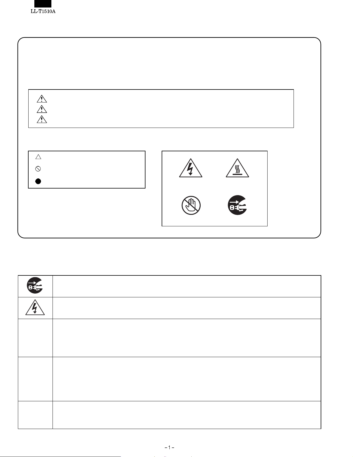
·Meaning of symbols ·Pictorial example
symbols mean the necessity of using caution.
symbols mean actions which are prohibited.
symbols mean actions to be required.
■Cautions in servicing
Locations which require a special caution carry safety instructions using labels and stamps on the cabinet, chassis and components.
When servicing, observe the instructions on such labels and stamps.
Electrical shock Hot surface
Don’t touch Remove power plug
Electrical shock and burn
1. Prior to servicing, make sure to remove the power supply plug.
Electrical shock
2. Some parts inside the unit have a high voltage. Use caution to avoid an electri cal shock accident when servicing an energized
unit.
Use specified parts
3. The component parts of this unit have safety characteristics such as flame resistance and dielectric strength.
· Use replacement parts which have the same characteristics as those of the components parts used for this unit.
· In particular, component parts marked with ! in t he circuit drawing parts list are important for maintaining the safety of the
product. Make sure to use specified replacement parts.
Reinstall component parts in their original locations and return wires which have been rerouted for servicing purposes
to their original positions.
4. Some component parts use insulating materials such as tubes or tape for safety purposes, or are mounted, a bi t floated, on the
printed wiring board.
· When rerouting inside wiring or clamping the wires, use caution not to bring the wires too close to heating or high-voltage parts.
· Make sure to return inside wiring to their original locations.
Check for safety after servicing.
5. After finishing servicing, check whether the screws, parts, wires which have been removed for servicing are reinstalled properly.
In addition, check to see if you have not deteriorated parts around the part you serviced, and also check for insulation between
each of the attachment plug terminals and the external metal section.
Page 3
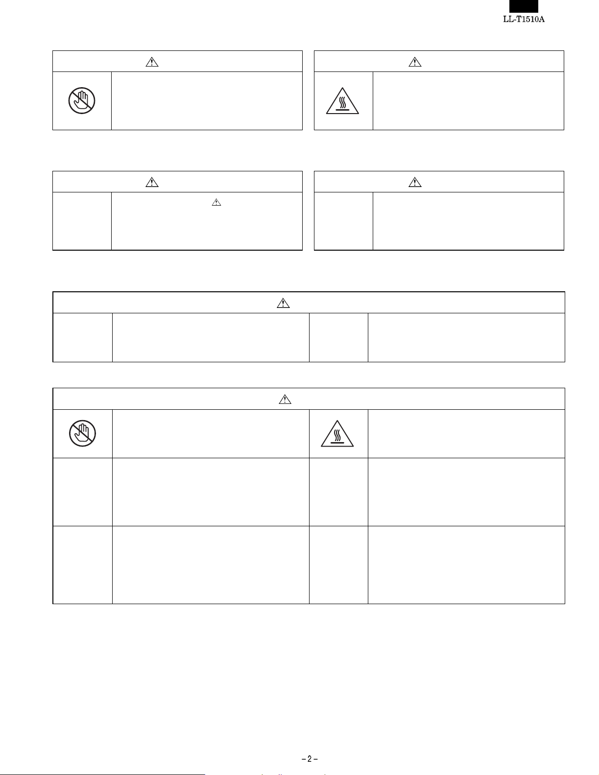
·Cautions to be taken when making adjustments
WARNING CAUTION
1. Use caution to avoid shorts due to the probe of
an oscilloscope or jigs and do not touch highvoltage circuits directly.
(There is fear of causing a fire or your getting an
electric short accident)
·Cautions to be taken when replacing electrical parts
WARNING CAUTION
1. Parts marked with are important for
maintaining the safety of the product. Use
specified parts when replacemzent of such parts
is required. (There is fear of giving off smoke,
catching fire, or your getting an electric shock)
·Cautions to be taken when soldering
WARNING
1. Do not try to solder when the parts are energized
or the unit is turned on.
(There is fear of causing fire or your getting an
electric shock.)
2. Use caution not to touch heating parts like the
radiating plate directly.
(You could get a burn.)
2. Use caution not to damage t he LCD unit when
handling it.
2. Use caution not to damage peripheral parts and
lead wires (e.g., burning peeling of coating).
(There is fear of causing a fire or your getting an
electric shock accident.)
CAUTION
1. Use caution not to touch a soldering iron directly.
(You could get a burn.)
3. Use caution not to have the wrong direction when
installing parts, if they need the installation of a
correct direction.
(There is fear of causing a fire.)
5. Some parts need to be installed at a specified
intervals or by a specified method for safety
purposes (they may be a bit floated from the board
for dissipating heat.). They must be reinstalled to
the original conditions.
(There is fear of causing a fire or your getting an
electrical shock accident.)
2. Make sure the radiating plate or heating parts are
cool enough not to get a burn before touching
such a part.
(You could get a burn.)
4. Use caution to avoid shorts due to an improperly
cut length of parts’ lead legs after soldering and
exercise care not to cut your finger with the edge
of cut surface.
(There is fear of causing a fire or your getting an
injury.
6. Use caution to solder in a correct manner so that
areas other than the part you want to solder are
contaminated with solder, like a solder ball or
bridge.
Page 4

·Cautions to be taken when disassembling or reassembling the unit
WARNING
1. Prior to servicing, make sure to remove the power
supply plug.
(You could get an electrical shock accident.)
3. Before servicing, make sure you know the
locations of high-voltage parts.
(You could get an electrical shock accident.)
CAUTION
1. When disassembling or reassembling the unit,
make sure to put the front cabinet side (LCD uni t
side) downward and carry out work using caution
not to get your fingers caught.
(Since the LCD unit side is heavier, there is fear of
your getting an injury due to tipping or falling.)
3. When disassembling the unit, use caution not to
get a burn because radiating plates and areas
around lamps on the PWB are hot immediately
after unplugging.
(You could get a burn.)
5. Pay attention to burrs or edges of the resin
(cabinet and PWBs) and metal (chassis and
others) parts.
(You could cut your finger with them.)
2. Use caution not to touch the inside of the product
with a wet hand or foot.
(You could get an electrical shock accident.)
4. Do not work on an unstable place or with t he stand
put upright. In particular, fix the cabinet before
replacing PWBs or fan.
(There is fear of your getting an injury due to
tipping or falling.
2. Use caution to avoid a reaction due to your
applying too much force when removing or
reinstalling screws.
(You could get an injury.)
4. Use caution not to get you fingers caught in the
stand pole, between the stand and angles or
under the cabinet.
(You could get an injury.)
6. Use caution to the deformation of the grounding
spring or the displacement of the ferrite core.
(There is fear of causing radio noises to other
equipment.)
·Cautions to be taken when replacing fluorescent lamp
CAUTION
1. Make sure the fluorescent lamp is cool enough not
to get a burn before you are going to touch the
lamp or areas around it.
(You could get a burn.)
3. Use caution not to break the fluorescent lamp
when handling it.
(You could get an injury.)
2. Use caution to avoid a reaction due to your
applying too much force when removing the
connector.
(You could get an injury.)
Page 5
CHAPTER 1. OUTLINE OF THE PRODUCT, NOMENCLATURE AND
FUNCTIONS
[1] Features
· 38 cm [15 type] 1024-dots x RGB x 768-line Anti-Glare and Low-
Refrection TFT color LCD panel
· 200 cd/m
2
high-luminance design
· Connectable to analog RGB output (for CRT)
Multi display mode function that supports resolutions from 640-dot
x RGB x 400-line to up to 1024-dot x RGB x 768-line
In modes lower than 800 x 600 dots, it is possible to enlarge the
screen that offers smooth and excellent visibility.
Supports VESA specification, Power Macintosh etc.
· Up to 16,190,000 colors are displayable
· Automatic screen adjustment
· The display timing and RGB gain can be more finely adjusted due
to the OSD guide function, in addition to the automatic adjustment
function.
· Power management function
· Supports Plug&Play (VESA:DDC1, DDC2B specifications)
[2] Safe servicing and safe inspection,
<When servicing or inspecting,
observe the safety instructions.>
1. Observe the cautions.
Locations which require a special caution carry safety instructions
using labels and stamps on the cabinet, chassis and components.
When servicing, observe the instructions on such labels and
stamps as well as those in the Instruction manual.
2. Exercise care not to get an electrical shock
accident.
Some parts have a high voltage inside the unit. Use caution when
handling them while they are energized.
3. Use specified parts.
The component parts of this unit have safety characteristics such
as flame resistance and dielectric strength. Use replacement parts
which have the same characteristics as those of the components
parts used for this unit. In particular, component parts marked
with ! in the circuit drawing parts list are important for maintaining
the safety of the product. Make sure to use specified replacement
parts.
4. Reinstall component parts in their original
locations and return wires which have been
rerouted for servicing purposes to their original
positions.
Some component parts use insulating materials such as tubes or
tape for safety purposes, or are mounted, a bit floated, on the
printed wiring board.
When rerouting inside wiring or clamping the wires, use caution
not to bring the wires too close to heating or high-voltage parts.
Make sure to return inside wiring to their original locations.
5. Check for safety after servicing.
After finishing servicing, check whether the screws, parts, wires
which have been removed for servicing are reinstalled properly. In
addition, check to see if you have not det eriorated parts around
the part you serviced, and also check for insulation between each
of the attachment plug terminals and the external metal section.
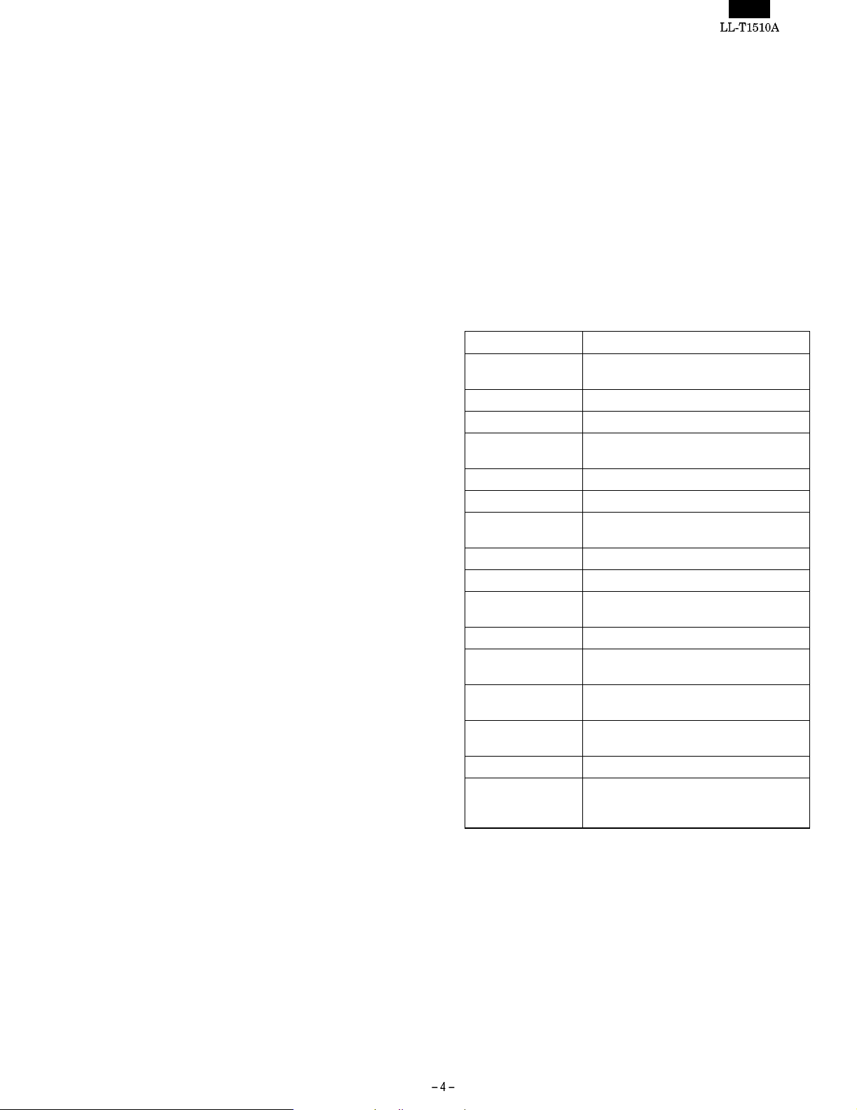
[3] Specifications
1. General specifications
Name of the product: LCD color monitor
Item Specifications
LCD display device 38 cm [15 type] super V & low reflective
black TFT liquid crystal
Picture element pitch 0.297 mm (horizontal) x 0.297 mm (vertical)
Display area 304.1 mm (horizontal) x 228.1 mm (vertical)
Number of picture
elements
Display color 16,190,000 colors (max.)
Input vide signal Analog RGB (0.7 Vp-p/75W)
Input synchronizing
signal
Input terminal 15-pin mini D-sub connector
Plug&Play VESA DDC1/DDC2B
Power management
function
Working temperature 5 ~ 35°C
Power supply D C+12 V, 100 AC 50/60Hz (when the
Power consumption 22 W (when USB hub is used) /max. 30 W
Outer dimensions about 362 mm (width) x 185 mm (depth) x
Weight approx. 5.2 kg
Accessories AC power supply cord (1), Instruction
· Specifications and a part of the appearance are subject to change
without notice.
1024 x RGB x 768 dots
Horizontal synchronizing signal TTL level
Compatible with VESA DPMS
adapter is used)
(when USB hub is used)
343 mm (height)
manual (1), warranty (1), adjustment disk
(1), USB cable (1)
Page 6
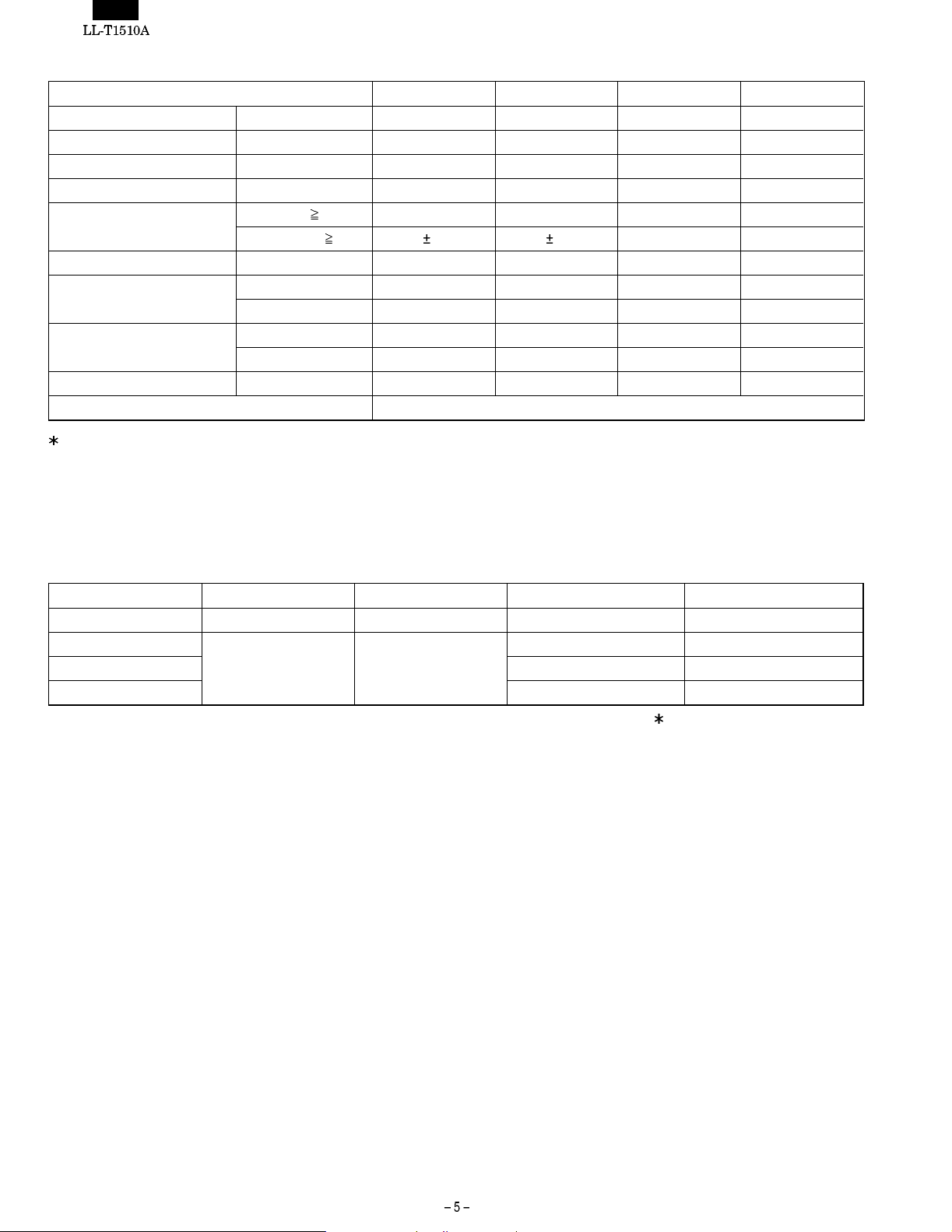
2. Technical specifications
Item MIN TYP MAX Unit
Power supply voltage AC 90 100 110 V
Working temperature range +5 — +35 °C
Storing temperature range -20 — +60 °C
Humidity range 20 — 85 %RH
Visual angle range Vertical (CR
Horizontal (CR
Contrast ratio(CR) (q = 0°) 200 300 — —
Response speed Leading (tr) — 10 25 ms
Trailing (td) — 35 50 ms
Screen white chromaticity (X) 0.283 0.313 0.343 —
(Y) 0.299 0.329 0.359 —
White surface luminance (Y
) 150 200 — cd/m
L
Module model number LQ150X1DR10
Specifications and a part of the appearance are subject to change without notice.
[Power management]
This unit supports DPMS*1 Energy Star*2.
To use the power management function of this unit, t he video card
and the computer must be compatible with the DPMS specifications.
*1 DPMS:Display Power Management Signaling
5) +40 ~ -50 +60 ~ -60 — Temperature
5) 60 70 — Temperature
2
DPMS mode Screen condition Power consumption Horizontal synchronization Vertical synchronization
ONSTATE Displayed state approx. 22 W * Yes Yes
STANDBY
SUSPEND Yes No
No display approx. 3 W
No Yes
OFFSTATE No No
At the time of the USB hub un- use
*2 Energy Star: We are a partner company of the International
Energy Star Program. We judges that this product conforms to the guidelines of the International
Energy Star program.
The International Energy Star program is a guideline introduced
by the Environmental Protection Agency that promotes energy
savings of office equipment including computers. It aims at promoting the development and use of products with a function that
suppresses energy consumption efficiently. Companies can participate voluntarily in this program at their own discretion. The
products that are allowed to participate in this program are office
equipment including computers, displays, printers, facsimile and
copiers, and the same criteria and marking (logo) are used among
partner countries.
[DDC*3(Plug & Play)]
This unit supports VESA’s DDC specifications
3
This monitor supports VESA DDC*
The DDC is a signal standard for ensuring plug&play function
between the monitor and personal computer and sends and receives information on resolution and others between the monitor
and personal computer. Plug&Play function can be used only
when the computer supports DDC and is configured to detect a
plug&play monitor.
Some DDC types are available according to different communication protocols.
This monitor supports DDC1 and DDC2B.
3
*
Display Data Channel
standard.
Page 7
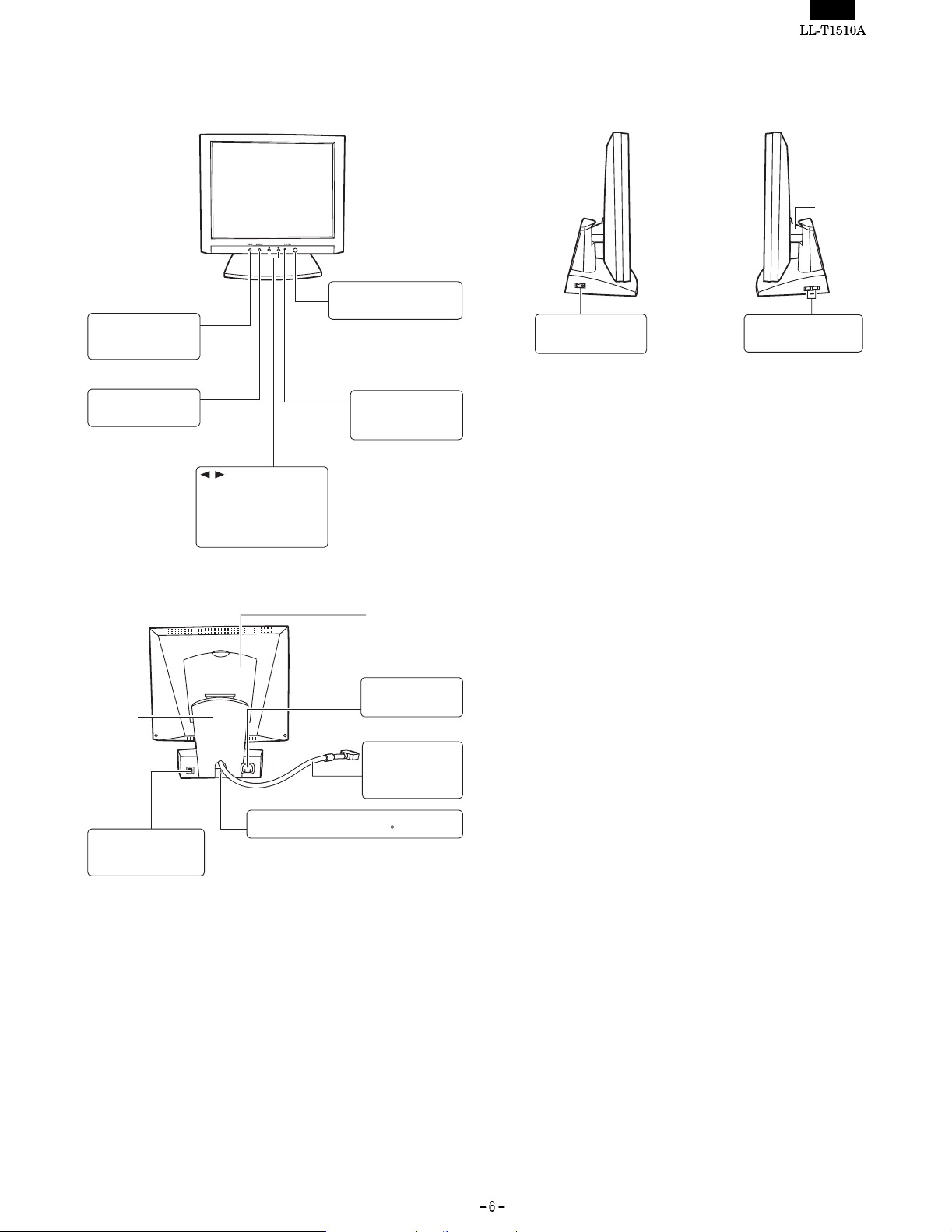
[4] Nomenclature and functions
[Front part]
MENU
This button is used to pop
up, select and close the
OSD menus.
SELECT
This button is used to
select the OSD options.
These buttons are used to:
1) Adjust the value of the
selected OSD option;
2) Adjust the brightness of the
backlight while the OSD
menus is not displayed.
Panel Power Button
This turns the panel power ON
or OFF.
Power LED
This indicator illuminates
when the power is turned
on.
[Side part]
Main Power Switch
This turns the monitorÕs
main power ON or OFF.
Connector Cover
USB Downstream Ports
These ports are for
connecting the USB devices.
[Rear part]
Stand Cover
USB Upstream Port
This port is for connecting a
USB downstream connector
on your PC or a USB hub.
Back Cover
Power Connector
This is for connecting the
power cable.
Signal Cable
This is for connecting the
monitor to the VGA
connector of the video
source (PC).
Lock Anchor
This is an anchor hole for Kensington type security lock.
Page 8
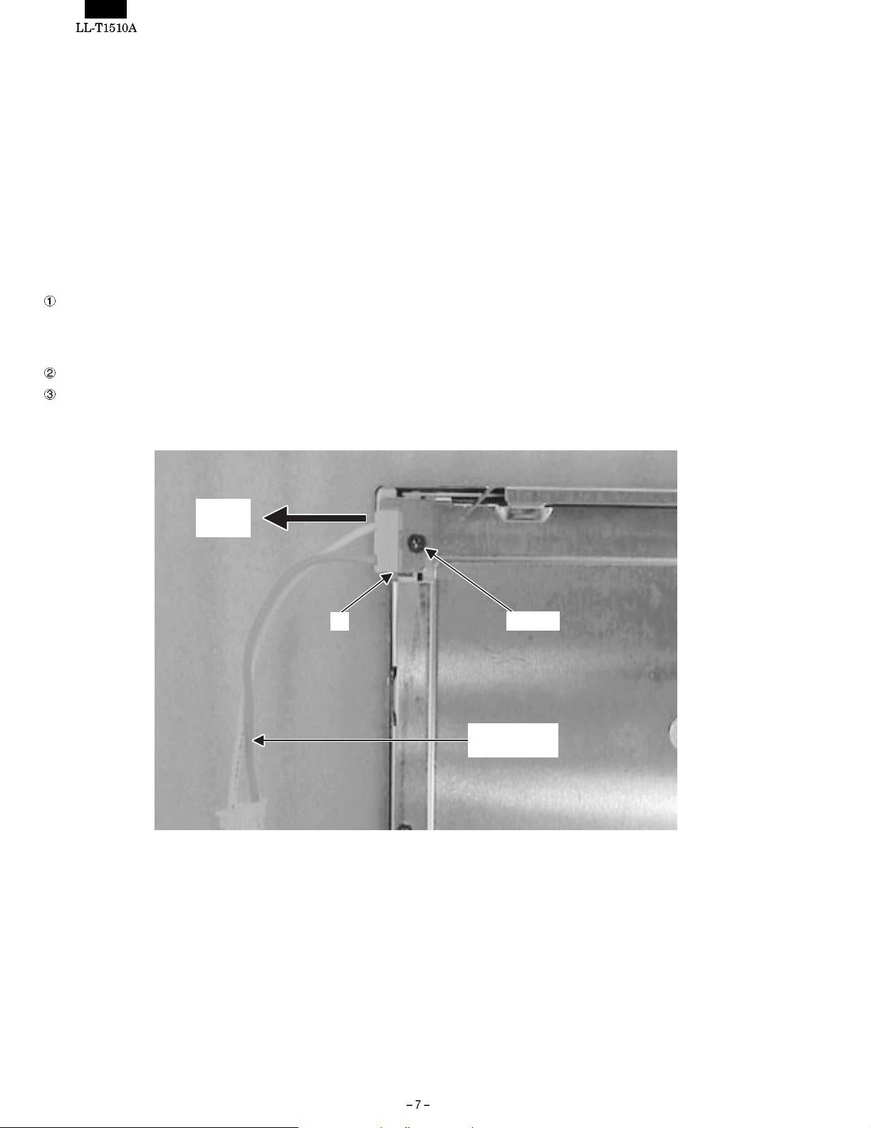
CHAPTER 2. REPLACING LAMPS (Removing LCD module)
[1] Replacing lamps
· After removing the LCD module from the unit according to 2. Re-
moving the LCD module, replace the lamp units.
· Replace the lamp units using the following replacement procedure,
referring to Fig.1 (enlarged view) and Fig. 2 (overall view).
· There are two lamp units at the top and bottom of the LCD
module.
· Wear finger sacks when doing this work, not to contaminate or
damage the LCD panel. Use caution prevent the entrance of
dirt or dust into the module.
[Replacement proce d u re]
Turn the module over and remove the screws A in Figs. 1. (1
screw for each unit). Put a finger on the concave B and remove
the lamp unit in a straight line.
· Use caution not to apply undue force on the lamp.
Replace the lamp unit with a new one.
Reinstall in the reverse order of disassembly.
· Tighten the screw and make sure the lamp unit won’t move.
Drawing
direction
B
Screw A
Fluorescent
lamp lead wire
Page 9
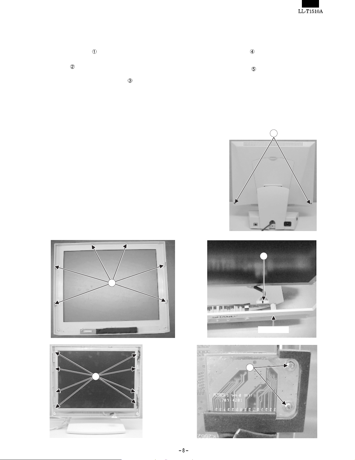
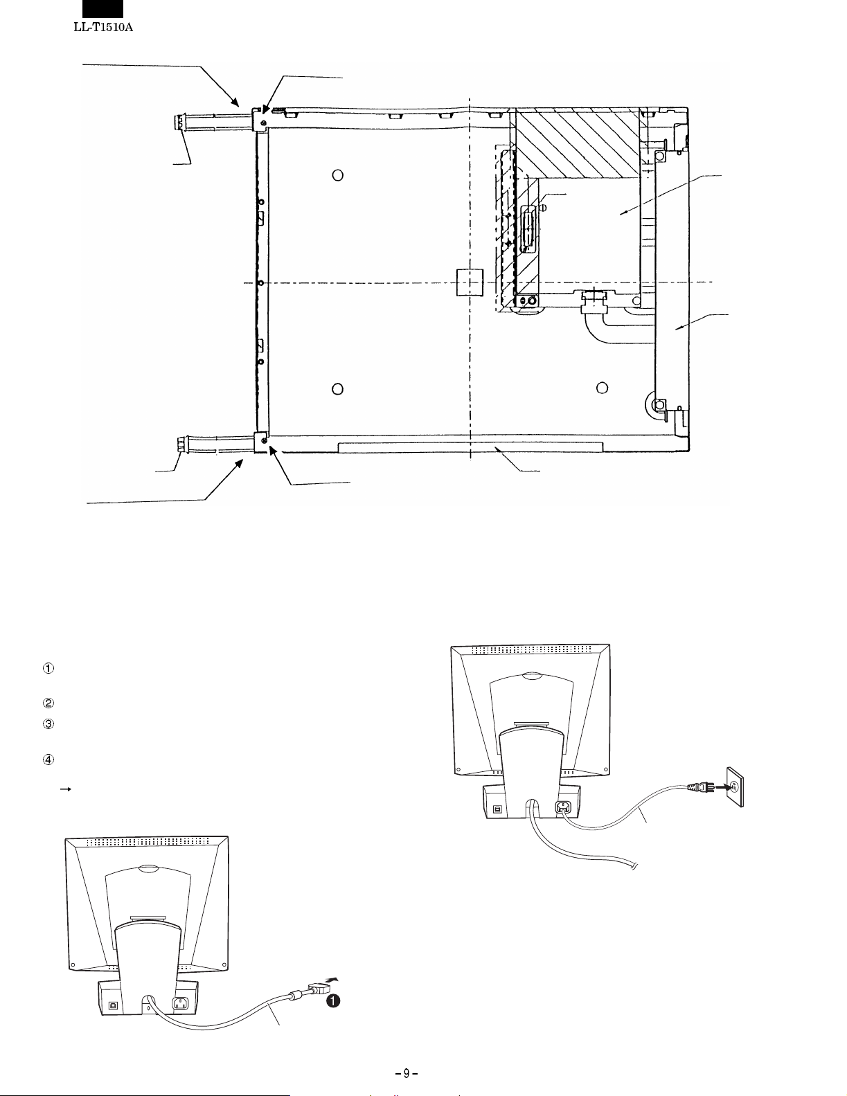
[2] Removing LCD module
Procedure
Disassembly
1. Remove the 2 screws in
cabinet).
· A connector is removed so that stress may not be applied to
the control circuit board cable when a front cabinet is removed.
· Use caution not to break the latches in when removing the
front cabinet.
and remove the display mask (front
2. Remove the 8 screws in
and remove the module.
· Use caution not to drop the LCD module.
3. Remove the 2 screws in
from the module.
Reassembly
Reassemble the LCD module using the steps from 1 to 3 in reverse.
and remove the LCD cable connector
· Use caution not to get the cables caught in the cabinet when
reassembling.
1
2
3
Front cabinet
5
4
Page 10
Upper fluorescent lamp lead wire
Screw A (upper)
CN2
CN2
Lower fluorescent lamp
lead wire
Screw A (lower)
Fig. 2
Cover
CN1
Cover
Tape
LCD module : VVLQ150X1DR10
Lamp umit : DUNTH2162TPZZ
CHAPTER 3. CONNECTION, ADJUSTMENT, OPERATION AND FUNCTIONS
[1] CONNECTING POWER SUPPLY AND
COMPUTER
· Make sure both the LCD monitor and computer are OFF.
Connect the signal cable to the analog output terminal of the
computer. Make sure to tighten the connector screws of the cable.
Connect the power supply cable to the wall outlet.
Turn on the main power switch of the monit or and then turn on the
computer power switch.
When the monitor power switch is turned on, the green power-on
lamp comes on and the screen appears. Adjust the screen
Automatic screen adjustment
After using the monitor, turn off the main power switch.
Rear view
To the computer
[CAUTION]
· When removing the power cable, make sure that both the com-
puter and the monitor are OFF and hold the connector, but not the
cable.
· When you are going to connect the monitor to a Power Macintosh
machine, you might need to a commercial Macintosh conversion
adapter.
To the AC outlet
Power cord
Signal cable
Page 11
cccccccccccccccccccccccccccccccccccccccccccccccccccc
@ZapfDingbats, Sffont, RingWorld3
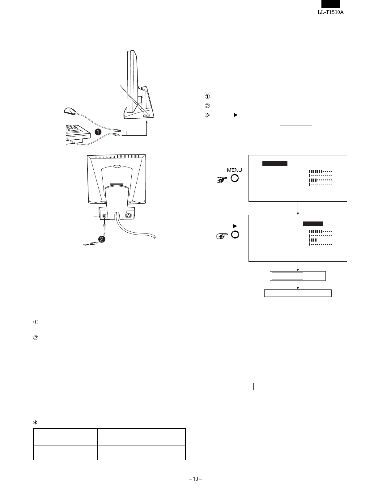
[2] CONNECTING USB CABLE
Rear view
USB Downstream ports
[3] ADJUSTMENT
3-1. AUTOMATIC SCREEN ADJUSTMENT
When the monitor is set up for the first time or when the system
setting is changed, make automatic screen adjustment. "CLOCK",
"PHASE" and "V-POs" are automatically adjusted to optimal values.
When making automatic screen adjustment, make sure that the entire
screen is bright.
Carry out automatic screen adjustment as follows:
Press the MENU button once. The [MENU1 ] appears on screen.
Select MANUAL on the [ADJUSTMENT] screen.
Press the button to select AUTO.
The screen becomes dark and
A few seconds later, the screen becomes bright again and the
MENU 1 appears on screen.
Menu 1
ACCD
[]
H
V
0x
12
ADJUSTING appears on screen.
J
U U
AA A
LOO
K
S
A
E
H
-
PPS
OPS-
LMMN
1
5
1
1
0
98
0 0
3
3
2
O
]
]
]
]
E
N
STTT
U
4678
HV60: Hz 8 Hzk:4
]
]
]
]
Upstream port
USB
This monitor comes equipped with a hub that supports USB standard.
The USB hub needs the following conditions:
· The computer to which the USB hub is connected and its OS are
compatible with USB standard.
· Or, the USB hub to which this USB hub is connected is also
connected to a USB-compatible computer (and OS).
When connecting any USB device to this monitor, use the USB cable
supplied with the monitor and observe the following conditions:
Connect the down-stream of a USB-compatible computer (or other
USB hub) with the up-stream of this monitor using the USB cable.
Connect the USB-compatible peripheral device to the USB down-
stream of the monitor.
[CAUTION]
Some USB peripheral devices might function properly depending
upon the type of computer, OS or peripheral equipment. For whether
the device you want to connect is USB compatible or not, consult the
manufacturer of the device.
The USB device connected to the USB connector of the monitor
operates when the main power supply is ON, even if the monitor is in
the power save mode or if the power switch on the front part of the
monitor is OFF.
USB-related specifications
USB standard Rev. 1.0 complicd self-powered hub
Down-stream supply power 500 mA for each port (MAX.)
USB port Up-stream x 1 (rear part), down-
stream x 2 (side part)
Menu 1
J
[]
LOO
H
H
-
V
12
0x
E
LMMN
U U
AA A
K
1
S
A
E
PPS
1
0
0 0
OPS-
4678
5
1
98
3
O
]
3
]
2
]
]
]
]
]
]
N
STTT
U
ACCD
HV60: Hz 8 Hzk:4
ADJUSTING
appears
Menu screen appears again.
The automatic screen adjustment has been thus completed.
Usually, you can use the monitor properly after carrying out automatic
screen adjustment . However, if you feel it necessary to fine-tune the
screen, use the adjustment diskette supplied with the monitor and
adjust the screen manually.
For the procedure for adjusting the screen manually, refer to the Fine
adjustment of the screen.
[CAUTION]
· If the entire screen is extremely dark, you might not be able to
perform automatic screen adjustment in some modes. In such a
case, the message
OUT OF ADJUST appears on screen, and
the settings remain unchanged.
Use the adjustment diskette supplied with the monitor or switch
the screen so that the entire screen looks bright and perform
automatic screen adjustment again.
· If the video signal from the computer is the composite sync or
sync-on-green, the screen might be adjusted properly after carrying out automatic screen adjustment. In such a case, fine adjust
the screen manually.
Page 12
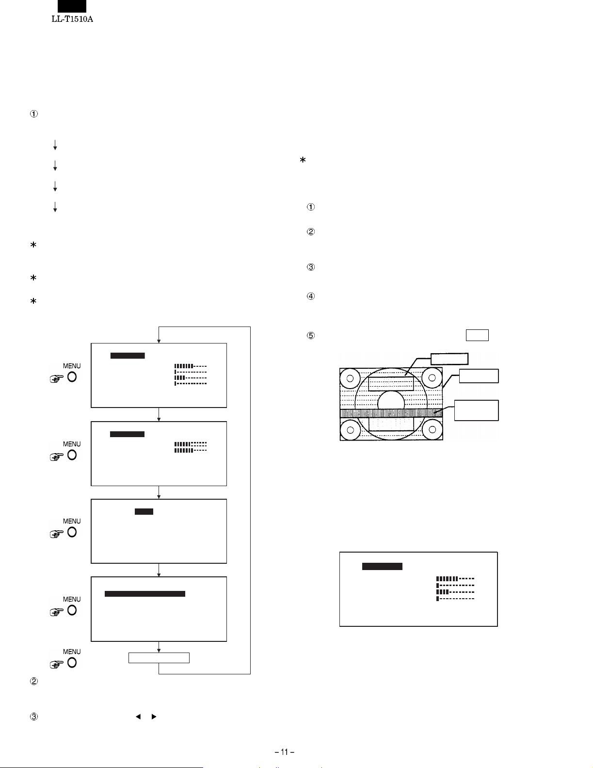
3-2. MANUAL SCREEN ADJUSTMENT
If fine adjustment of the screen is necessary, use the adjustment
diskette (for Windows) supplied with the monitor t o adjust the screen
manually. If you want to fine adjust computers whose OS is other
than Windows, follow the instructions on the screen.
1. OUTLINE OF ADJUSTMENT
Every time the MENU button is pressed, the screen is switched
over as follows:
Menu 1 (ADJUSTMENT)
Menu 2 (GAIN CONTROL)
Menu 3 (WHITE BALANCE)
Menu 4 (MODE SELECT)
Menu is deleted.
It changes.
On all the MENU screens, the resolution of the input signal, vertical
synchronizing frequency (V), horizontal synchronizing frequency
(H) appear at the lower part of the screen in rough values.
The values of "R-CON, G-CONT. B-CON" on the MENU 3 screen
are indicated only when "WHITE BALANCE" is in the USER.
On the MENU 4 screen, you can select menu options, but the
display status might not change, depending upon the resolution of
the input signal.
Menu 1
E
S
ACCD
J
[]
LOO
H
-
H
V
0x
12
Menu 2
GAI
[]
ROI
O
C
O
0x
12
Menu 3
WORH-I
[]
CBO
-C
G
B
124 6780x
Menu 4
OD
M
[]
SRD
0
S
H
GIH EMDUIM OLWH
124 6780x
Select the menu option you want to adjust, using the SELECT
button. Every time the button is pressed, the highlight moves
downward.
Adjust or switch over using or button.
N
TT
U
AA A
LMMN
U U
3
1
K
5
2
1
A
S
E
1
98
0
PPS
4678
N
N
LCR
4678
T
C
C-ON
E
0
A4P
3
0 0
OPS-
HV60: Hz 8 Hzk:4
N
T
CROL
AA A
LMON
U U
4
T
6
GB
H
2
7
T
HV60: Hz 8 Hzk:4
E
L
A
A
•OR
LM
• WA
SDT
T
N
T
ON
T
HV60: Hz 8 Hzk:4
SLETCE
H-SO
POD
OPTIS
O
V-
NI
E
LS
N
T
]
]
]
]
]
]
62 0K 16M
NE
C
T
I SNOI
NOI
046027
SES
HV60: Hz
8Hzk:4
O
O T
U
ESR
Menu is deleted.
]
]
]
]
]
]
[CAUTION]
If the button operation is suspended for about 15 seconds during adjustment, the menu on screen will disappears.
Screen adjustment needs to be performed whenever the screen
mode (resolution, refresh rate and others) has been changed. The
adjustment results are automatically stored in memory and effect ive
after the power is turned off. Therefore, once the screen is adjusted
properly, there is no need to adjust the screen every time you use the
monitor.
2. HOW TO USE ADJUSTMENT PROGRAM
The following explanation is written on the assumption that the OS
is Windows 95/98.
In addition, the floppy disk drive is assumed to be drive A.
START
Insert the "Adjustment diskette" supplied with the monitor into
drive A.
Open "3.5" FD (A:)" in the "My computer".
(In the case of Windows 3.1, open the "File manager" and
select drive A.
Double click "Adj_Uty.exe" to start the adjustment program.
ADJUSTMENT
The adjustment pattern as shown on the right sketch appears
on screen and adjust, following the instructions on the screen.
END
When the adjustment is completed, press ESC key on the
keyboard to exit the adjustment program.
Color pattern
Display frame
White and black
lines alternate.
[CAUTION]
If your computers display mode is 65000 colors, the gradation of each
color of the color pattern might look different or gray scales look
tinted. It is not a problem, but due to the specification of the input
signal.
3. ADJUSTMENT ITEMS
[MENU 1] ADJUSTMENT
Adjust "CLOCK", 2PHASE", "H-POs" and V-POs".
ACCD
J
U
[]
LOO
A
H
H
PPS
-
V
12
4678
0x
MANUAL: Adjust manually. (Select the adjustment item you want
to adjust using the SELECT button.)
AUTO: The automatic screen adjustment function works t o ad-
just "CLOCK", "PHASE", "H-POs" and "V-POs" automatically to optimal values.
During the adjustment, the screen becomes dark and
indicates ADJUSTING.
N
STTT
E
AA A
LMMN
U U
K
5
3
1
E
S
OPS-
1
1
98
0
3
0 0
2
HV60: Hz 8 Hzk:4
O
]
]
]
]
]
]
]
]
Page 13
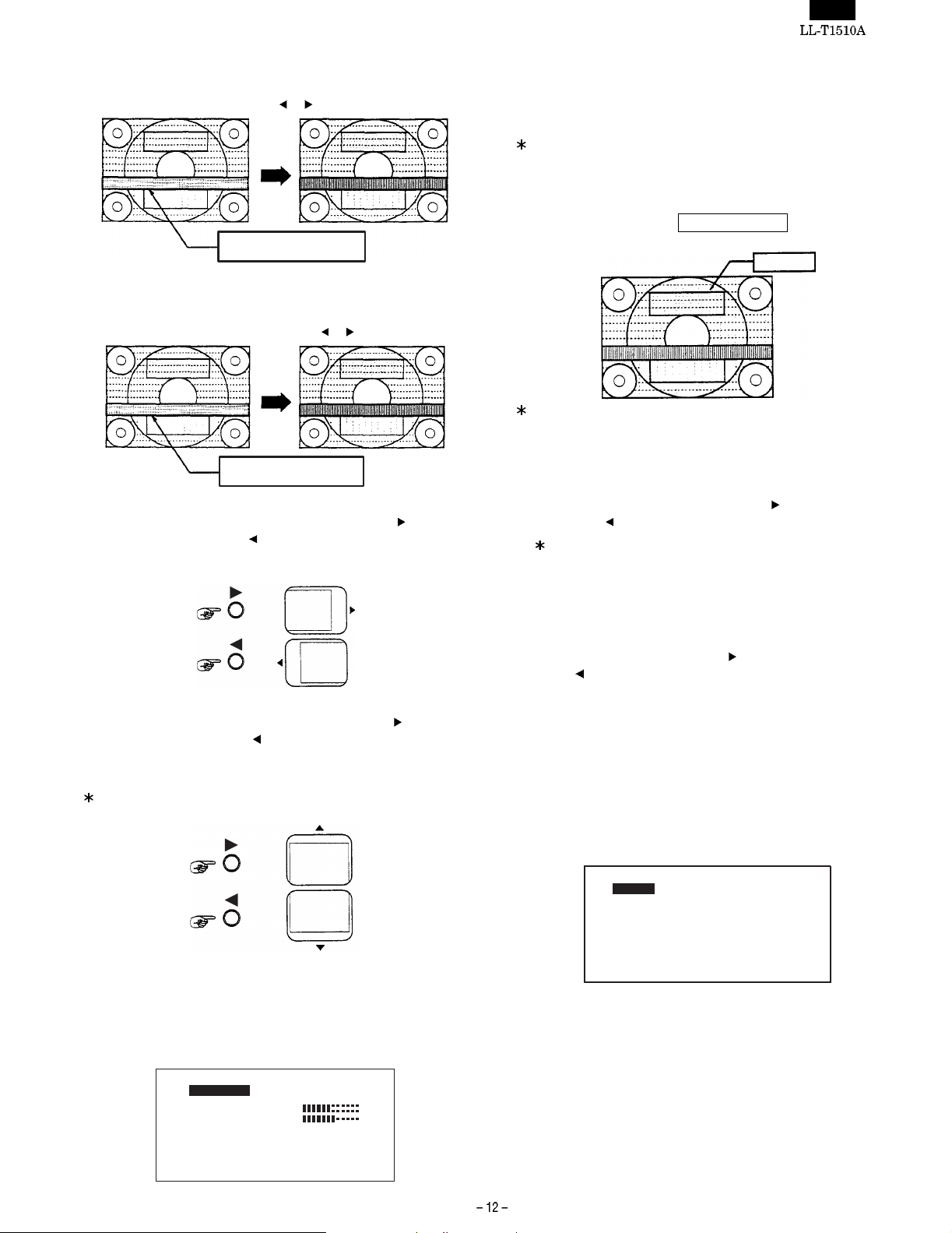
CLOCK
Adjust the pattern that white and black lines alternate so that there
is a noise (vertical stripe), using
Horizontal stripes-like noise
or button.
PHASE
Adjust the pattern that white and black lines alternate so that the
horizontal stripe noise is reduced to minimum and that the white
and black pattern looks clear, using the
Horizontal stripes-like noise
or button.
H-POS
You can move the screen to the right by pressing the
to the left by pressing the
button. Adjust the horizontal position
button and
of the screen so that both the right and left frame lines of the
pattern appear on screen.
V-POS
You can move the screen upward by pressing the
downward by pressing the
button. Adjust the vertical position of
button and
the screen so that both the top and bottom frame lines of the
pattern appear on screen.
Make sure to adjust "CLOCK" properly before proceeding with the
adjustment of "PHASE".
MANUAL: Adjust manually. (Select adjustment options using the
SELECT button.)
AUTO: The auto gain control function works to adjust the bright-
ness and contrast automatically to optimal values.
The auto gain control function adjust the brightness and contrast
based on the brightest color being displayed on the screen. If you
use this function without displaying the adjustment pattern on
screen, at least a 5 mm x 5 m m white area needs to be displayed
on screen. If not, you might not be able to make the adjustment. I n
such a case, the message
OUT OF ADJUST appears on screen
and the settings remain unchanged.
Color pattern
To execute the auto gain control function, set to the "COOL, STD,
WARM" mode on the "MENU 3. WHITE BALANCE" screen. If the
monitor is in the USER mode, the auto gain control won’t work.
BRIGHT (brightness)
Adjust the brightness of the entire screen.
The screen becomes brighter by pressing
pressing the
button.
button and darker by
You can also adjust the brightness of the light source (backlight) of the LCD monitor. For more information, see "Adjusting
backlight brightness."
CONT (contrast)
Adjust the contrast on the color pattern screen on the adjustment
program so that all gradations can be displayed. The contrast
becomes stronger by pressing the
ing the
button.
button and weaker by press-
COLOR (number of displayable colors)
Set the maximum displayable colors (1,6190,000 colors or
260,000 colors)
[MENU 3] WHITE BALANCE
Adjust the color of the screen.
The monitor is factory adjusted properly about the color of the screen,
and thus there is not necessary to adjust it . If adjustment of the whi te
balance is required for any reason, select the adjustment options
using the SELECT button and adjust it.
SDT
T
T
T
NE
L
A
C
A
• WA
R
ESR
M
U
E
WORH-I
T
[]
O
CBO
-C
G
B
•
L
N
ON
C
C-ON
[MENU 2] GAIN CONTROL
Adjust the brightness and contrast of the screen.
The monitor is factory adjusted properly. However, it might need to
be adjusted depending upon the type of computer to which the monitor is connected. Adjust the brightness and contrast, observing the
color pattern of the adjustment program.
GAI
N
[]
ROI
N
O
C
LCR
O
12
4678
0x
T
CROL
N
AA A
LMON
U U
6
4
T
GB
H
7
T
2
HV60: Hz 8 Hzk:4
O T
]
]
62 0K 16M
]
]
124 6780x
HV60: Hz 8 Hzk:4
COOL - STD - WARM
You can select the color you want from among the 5 preset
modes.
COOL : Bluish than the standard setting.
■
: A little bluish than the standard setting.
STD : Standard setting
■
: A little reddish than the standard setting
WARM : Reddish than the standard setting
Page 14

USER
You can adjust the color of the screen more finely, using R-CONT,
G-CONT, and B.CONT.
R-CONT: The
G-CONT: The
B-CONT: The
When the mode is set to "COOL" or "WARM", you cannot
display all gradations. If you want to display all gradations, set
the mode to "STD."
[MENU 4] MODE SELECT
Select the adjustment option you want to adj ust using the SELECT
button and adjust each mode of the monitor.
OSD H-POSITION (OSD screen horizontal position)
Adjust the horizontal position (lateral direction) of the adjustment
menu on the screen.
You can move the menu to the right by pressing the
to the left by pressing the
OSD V-POSITION (OSD screen vertical position)
Adjust the vertical position (vertical direction) of the adjustment
menu on the screen.
You can move the menu upward by pressing the
downward by pressing the
400LINE (resolution)
Adjust the horizontal resolution of t he 400-line screen for the PC9800 series or US TEXT.
[640] : 640 x 400 dot mode
[720] : 720 x 400 dot mode (for US TEXT and others)
SHARPNESS: (enlarged correction level)
The screen whose display mode is less than 1024 x 768 dots
appears in an enlarged size (1. Corresponding signal timing)
You can select the sharpness of an enlarged image from three
levels (HIGH, MEDIUM, LOW).
button makes the color of the screen more reddish; the
blue-greenish.
ish; the
purplish.
the
lowish.
M
[]
124 6780x
button makes the color of the screen more
button makes the color of the screen more green-
button makes the color of the screen more
button makes the color of the screen more bluish;
button makes the color of the screen more yel-
OD
E
SLETCE
H-SO
POD
T
I SNOI
S
GIH EMD UIMOLWH
SRD
0
H
0
A4P
OPTIS
O
V-
NI
E
LS
N
button.
button.
NOI
046027
SES
HV60: Hz
8Hzk:4
button and
button and
4. Adjusting backlight brightness
When the or button is pressed with no adjustment menu displayed on screen, the BRIGHT menu appears on screen. You can
adjust the brightness of the backlight on this menu.
The
button makes the backlight brighter and the button makes it
darker.
5. ALL RESET
You can return all the settings to the fact ory settings using the procedure given below.
Turn off the power of the monitor using the power button on its
front.
Press and hold the MENU and SELECT buttons, press the power
button on the front of the monitor to turn it on.
The message ALL RESET appears on screen and the monitor
is reset.
Note: While
ALL RESET appears on screen, any button opera-
tion is invalid.
6. Adjustment lock function
To protect the settings and adjusted values from the wrong operation,
set the adjustment lock. If the adjustment lock is activated, no menu
screen won’t appear on screen so that you cannot set or change the
settings.
Adjustment lock ON: Press and hold the MENU button and turn
on the power button on the front of the
monitor.
Adjustment lock OFF:Turn off the power button on the front of the
monitor. Press and hold the MENU button,
turn on the power button on the f ront of the
monitor.
When the adjustment lock is ON, you cannot carry out any button
operation without the power button.
3-3. APPLICABLE SIGNAL TIMING
Display mode Horizontal
VESA
(IBM AT
compatible
machines)
US TEXT
Power Macintosh
All signal timings are applicable for non-interlace only.
The frequencies for Power Macintosh are reference values.
When you want to connect this monitor to Power Macintosh, you
might need to use a commercial Macintosh conversion adapter.
[CAUTION]
640 x 400 31.5kHz 70Hz 25MHz
640 x 480 31.5kHz 60Hz 25. 175MHz
800 x 600 35.1kHz 56Hz 36.0MHz
1024 x 768 48.4kHz 60Hz 65.0MHz
720 x 400 31.5kHz 70Hz 28.3MHz
640 x 480 35.0kHz 67Hz 30.5MHz
832 x 624 49.7kHz 74.6Hz 57.3MHz
1024 x 768 60.2kHz 75Hz 80.0MHz
frequency
37.9kHz 72Hz 31.5MHz
37.5kHz 75Hz 31.5MHz
37.9kHz 60Hz 40.0MHz
48.1kHz 72Hz 50.0MHz
46.9kHz 75Hz 49.5MHz
56.5kHz 70Hz 75.0MHz
60.0kHz 75Hz 78.75MHz
Vertical
frequency
Dot
frequency
· If any signal timing not applicable to thi s monitor is inputted, the
message
onds before the screen becomes blank.
If this is the case, set the monitor t o one of the applicable signal
timings, referring to the Instruction Manual of your computer.
OUT OF TIMING appears on screen for about 5 sec-
· If no signal (synchronizing signal) is inputted to this monitor, the
message
and then the screen becomes blank.
NO SIGNAL appears on screen for about 5 seconds
Page 15

3-4. CONNECTOR PIN LAYOUT
Mini D-sub connector, 15 pins
Input connector
Pin No. Function
1 Red video signal input
2 Green video signal input
3 Blue video signal input
4GND
5GND
6 GND for red video signal
7 GND for green video signal
8 GND for blue video signal
9N.C.
10 GND for synchronizing signal
11 GND
12 DDC data
13 Horizontal synchronizing signal input
14 Vertical synchronizing signal input
15 DDC clock
Page 16

CHAPTER 4. TROUBLESHOOTING (for checking PWBs)
Make sure that the following accessory cables are connected properly.
In addition, make sure that the video mode of the personal computer is properly set to the signal timing supported by this machine.
ACCESSORY CABLES
· Power cable
· USB cable
Check for defective parts in the
following manner.
Does the light of the LED change from orange
to green when pressing the power-on switch?
Yes
Remove the RGB cable. Does LED
come on in orange after for a while?
Yes
Connect the RGB cable.
Does the backlight come on?
Yes
Does the screen display normally
in each video mode?
Yes
Do the USB units operate normally? (5) See <USB error>.
Yes
No error
(1) <An error occurs when detecting the synchronizing signal>
Is DC+12V outputted from the
power supply unit?
Yes
Is B13 at DC+12V?
Yes
Is the signal input of the 5th pin of
the U17 at low level (0V)?
Yes
Is the 4th pin of the U17 at DC+15V?
Yes
Is the signal input of the 11th pin of
the U10 at low level (0V)?
Yes
Is the signal input of the 22nd pin of the
U10 normal? (See Waveform diagram 1.)
Yes
Is the signal input of the 4th pin of
the U16 at low level (0 V)?
Yes
Is the 8th pin of the U16 at DC+12V?
Yes
Is the signal input of the 17th pin of the U10
normal? (See Waveform diagrams 2, 3.)
Yes
Is the signal output of the 27th pin of
the U10 at low level (0 V)?
Yes
Is the signal output of the 42nd pin of
the U10 at high level (DC+5V)?
Yes
Check the operation PWB and related
parts (LED and cables).
No
No
No
No
No
No
No
No
No
No
No
No
No
No
No
No
(1) See <An error occurs when detecting the
synchronizing signal.>
(2) See <An error occurs when using the
Power Save mode>
(3) See <Backlight goes out improperly>.
(4) See <Screen error>
Check the power supply unit and
fuses (power supply unit).
Check the DC+12V power line (12V), and the
power supply circuit for the fuse F1.
Check the power supply circuit for the operation PWB
(operation PWB and cables) and that for the U17.
Check the DC+15V power supply line (5Va)
and the power supply circuit for the U17.
Check the REST circuit for the U10.
Check the clock circuit for the U10 and X1.
Check the power supply circuit for the operation PWB
(operation PWB and cables) and that for the U16.
Check the DC+12V power line (12 Va) and
the power supply circuit for the U16.
Check the signal cable and the synchronizing
signal processing circuit for the U10 and U21.
Check the microprocessor control circuit
for the U10.
Check the microprocessor control circuit
for the U10.
Page 17

(2) <An error occurs when using Power Save mode>
Is the signal input of the 42nd pin of
the U10 at low level (0 V)?
Yes
Check the operation PWB and related
parts (LED and cables).
(3) <Backlight goes out improperly>
Is the 5th pin of the JP2 at DC+12V?
Yes
Is the signal input of the 26th pin of
the U10 at low level (0 V)?
Yes
Is the 1st pin of the JP2 at DC+5V?
Yes
Is the 26th pin of the U17 at 0 V when
the backlight luminance is at the
maximum (OSD BRIGHT31)?
Yes
Is the 3rd pin of the JP2 at 0 V when the
backlight luminance is at the maximum
(OSD BRIGHT31)?
Yes
Are the 1st pins of the inverter PWB
units CN2 and 3 at about 1500 Vrms?
(Use due caution not to get an electric
shock accident. For measuring the
voltage, use a high-voltage probe of
more than 100:1. )
Yes
Check the lamp inside the LCD module.
No
No
No
No
No
No
No
Check the microprocessor control circuit
for the U10.
Check the CD+12V power line (12 V) and
the power supply circuit for the JP2.
Check the microprocessor control circuit
for the U10.
Check the DC+5V power line (5 Va) and the
power supply circuit for the U17.
Check the operation PWB (operation PWB
and cables) and the microprocessor control
circuit for the U10 and U17.
Check the backlight control circuit for the JP2.
Check the inverter PWB unit.
(5) <USB error>
Is DC+12 V outputted from the
power supply unit?
Yes
Replace the USB unit with a new one.
No
Check the power supply unit and
fuses (power supply unit).
Page 18

(4) <Screen error>
Is the signal output of the 25th pin of
the U10 at low level (0 V)?
Yes
It the 8th pin of the U18 at DC+5V?
Yes
Is the signal output of the 1st pin of
the U12 at high level (Cd+5 V)?
Yes
Is the 2nd pin of the U14 at CD+3.3 V?
Yes
Does the entire screen of the LCD
remain white?
No
No
No
No
No
Yes
Check the microprocessor control circuit for
the U10.
Check the DC+5 V power supply line (% Vb)
and power supply circuit for the U18.
Check the power supply control circuit for
the U12.
Check the DC+3.3 V power supply line (3.3 Vb)
and the power supply circuit for the U14.
Are the signal outputs of the 9th and 14th pins
of the JP4(See Waveform diagrams 4 and 5.)
Check the LCD connector and LCD module.
No
Check the LCD control signal
circuit for the U1 and U3.
Does the entire screen of the LCD
remain black?
No
Is the size of the LCD screen abnormal?
No
Does the LCD screen jolt or flicker?
No
Do the colors of the LCD screen
abnormal?
No
Yes
Yes
Yes
Yes
Check the LCD control signal circuit for
the U1 and U3.
Are the adjustment items, ADJUSTMENT,
MODE, and SELECT, properly set?
Are the output signals of the 15th pin of the U5
and the 8th pin of the U2 normal?
(See Waveform diagrams 6 and 7.)
Check the LCD control signal circuit for
the U1 and U3.
Are the adjustment items ADJUSTMENT,
MODE, and SELECT set properly?
Check the PLL circuits for the U2,
U4, U5, U6, U10, and U11.
Are the adjustment items GAIN, CONTROL,
and WHITE BALANCE properly set?
Are the analog color signal outputs of the 29th
pin, 32nd pin, and 35th pin of the U properly
set? (See Waveform diagram 8.)
Is the digital color signal output of the U2
normal? (See Waveform diagram 9.)
No
No
No
No
No
No
Adjust and set the adjustment
items properly, following the
screen adjustment procedure.
Check the PLL circuits for the
U2, U4, U5, U6, U10, and U11.
Adjust and set the adjustment
items properly, following the
screen adjustment procedure.
Adjust or set the adjustment
items, following the screen
adjustment procedure.
Check the video amplifier
circuit for the U7.
Check the AD conversion
circuit for the U2.
Is the OSD display of the LCD screen
abnormal?
No
Is the LCD screen normal at the time of
composite sync or sync-on green?
Yes
Are the settings of the display screen
adjustments properly stored in memory?
Yes
The LCD unit is normal.
Yes
No
No
Is the digital color signal input and output of
the U1 normal? (See Waveform 10.)
Check the LCD connector and LCD module.
Are the signal outputs of the 13th pin, 14th pin
and 15th pin of the U8 normal?
(See Waveform diagram 11.)
Check the color signal processing circuit for
the U1 and U3.
Check the synchronizing signal processing
circuit for the U7, U19, U21, U22 and U23.
Check the memory circuit for the U10 and u11.
No
No
Check the color signal
processing circuit for the U1
and U3.
Check the OSD display circuit
for the U8, U10, and U11.
Page 19

CHAPTER 5. TRIMMING AND PROCESSING LEAD WIRES
Step 1
Put the CCFT cable and LCD cable into shield plate bushi ngs to
prevent them from getting caught when installing the shield plate.
(Figs. 1 and 2)
Put the CCFT cable at the back of t he LCD module to prevent it
from getting caught when installing the LCD module.
CCFT cable
Power supply
cable
Switch cable
LCD cable
Fig. 1 Fig. 2
Step 2
When installing the hinge cover, use caution not to get the power
cable and the LCD cable caught in the cover. (Fig. 3)
Fig. 3
Power supply
cable
LCD cable
Page 20

CHAPTER 6. WAVE FORM
Waveform measurement condition: Input each of the display patterns
and measure the waveform (timing chart).
Wave-form
No.
1 22nd pin of the U10 X1 Arbitrary
2 17th pin of the U10 TO_MCU_V Arbitrary
3 15th pin of the U10 TO_MCU_H Arbitrary
4 8th pin of the JP4 CLK Arbitrary
5 14th pin of the JP4 BDE_OUT Arbitrary
6 15 pin of the U5 DS Arbitrary
7 8th pin of the U2 CLKOUT Arbitrary
8 29th pin, 32nd pin, and 35th pin of the U7 PRE-Amp RGB OUT 16 monochromatic gradation patterns
9 52nd ~ 59th pins and 62nd ~ 89th pins of (R) of the U2
32nd ~ 39th pins and 42nd ~ 49th pins of the (G) of the U2
12th ~ 19th pins and 22nd ~ 29th pins of (B) of the U2
10 53rd ~ 59th pins, 63rd ~ 69th pins, and 73rd ~ 79th pins, 83rd ~
89th pins, 93rd ~ 99th pins, and 103rd and 109th pins of the U1
11 13th, 14th, and 15th pins of the U8 OSD COLOR DATA Black pattern on e ntire screen OSD menu
Measurement point Name of waveform Display pattern
A/D OUT DATA Monochrome pattern at every 2 lines
ASIC OUT DATA Monochrome pattern at every 2 lines
display
CAUTION
(1) Use the probe TektronixP6139A.
(2) Reception mode: VESA 1024 x 768 H:60.024 Khz
V:75.075 Hz DOTCLK: 78.750MHz
Oscilloscope : Tektronix TDS744A
Input signal : VESA1024 x 768
H: 60.02 kHz V: 75.075 Hz
DOTCLK: 78.750 MHz
WAVE FORM 1 : X1(22th pin of the U10.)
Frequency : 8.000MHz
Display screen : arbitrary
WAVE FORM 2 : TO_MCU_V(17th pin of the U10.)
Frequency : 75MHz
Display screen : arbitrary
Page 21

WAVE FORM 3 : TO_MCU_H(15th pin of the U10.)
Frequency : 60 KHz
Display screen : arbitrary
WAVE FORM 6 : DS(15th pin of the U5.)
Frequency : 60 KHz
Display screen : arbitrary
WAVE FORM 4 : CLK(8th pin of the JP4.)
Frequency : 35 MHz
Display screen : arbitrary
WAVE FORM 5 : BDE_OUT(14th pin of the JP4.)
Frequency : 60 KHz
Display screen : arbitrary
WAVE FORM 7 : CLKOUT(8th pin of the U2.)
Frequency : 40 MHz
Display screen : arbitrary
WAVE FORM 8 : PRE-Amp RGB_OUT
(29th pin ,32dn pin, 35th pin of the U7.)
Display screen : monochrome 16 pattern
Page 22

WAVE FORM 9 : A/D OUT DATA
(52nd~59th pins and 62nd~69th pins of the U2 (R)
32nd~39th pins and 42nd~49th pins of the U2 (G),
12th~19th pins and 22nd~29th pins of the U2 (B))
Display screen : monochrome pattern at every 2
Enlargement
WAVE FORM 11 :CSD COLOR DATA
(13rd pin, 14th pin, 15th pin of the U8)
Display screen : all black pattern
OSD menu display
lines
Enlargement
WAVE FORM 10 :ASIC OUT DATA
(53rdh~59th pins and 63rd~69th pins and
73rd~79th pins and 83rd~89th pins and 93th~99th
pins and 103rd~109th pins of the U1)
Display screen : monochrome pattern at every 2
Enlargement
lines
Page 23

CHAPTER 7. BLOCK DIAGRAM / UNIT TERMINALS
LCD UNIT
LANP
1 LCD SIGNAL INPUT
RGB, H/V
INPUT
6J1
15 inch LCD
LANP
INTERFACE
UNIT
3J2
INVERTER
2 JP2
4J3
5 JP1
AC ADAPTER
AC100V
INPUT
AC 100V
INPUT
AC SOKET
AC SW
DOWNSTRAEM
DOWNSTRAEM
Unit terminals
LCD SIGNAL INPUT
Used connector : FX8-60P-SV (HIROSE)
Pin No. Symbol Function
1GNDGND
2 RB0 RED
3RB1RED
KEY-SWITCH UNIT
POWER UNIT
JP1
7
USB HUB UNIT
(LSB)
UPSTRAEM
Pin No. Symbol Function
4RB2RED
5RB3RED
6RB4RED
7 RB5 RED (MSB)
8GNDGND
9 GB0 GREEN
10 GB1 GREEN
11 GB2 GREEN
(LSB)
Page 24

Pin No. Symbol Function
12 GB3 GREEN
13 GB4 GREEN
14 GB5 GREEN (MSB)
15 GND GND
16 BB0 BLUE
17 BB1 BLUE
18 BB2 BLUE
19 BB3 BLUE
20 BB4 BLUE
21 BB5 BLUE (MSB)
22 GND GND
23 RA0 RED
24 RA1 RED
25 RA2 RED
26 RA3 RED
27 RA4 RED
28 RA5 RED (MSB)
29 GND GND
30 GA0 GREEN
31 GA1 GREEN
32 GA2 GREEN
33 GA3 GREEN
34 GA4 GREEN
35 GA5 GREEN (MSB)
36 GND GND
37 BA0 BLUE
38 BA1 BLUE
39 BA2 BLUE
40 BA3 BLUE
41 BA4 BLUE
42 BA5 BLUE (MSB)
43 GND GND
44 REV1 (GND)
45 GND GND
46 Vsync Vertical synchronizing signal
47 Hsync Horizontal synchronizing signal
48 DE Data enable signal
49 GND GND
50 GND GND
51 CKB Sampling clock
52 CKA Sampling clock
53 GND GND
54 GND GND
55 REV2 (GND)
56 REV3 (GND)
57 Vcc +5V power supply
58 Vcc +5V power supply
59 Vcc +5V power supply
60 Vcc +5V power supply
JP2 (To Inverter Terminal)
Used connector : PH5PS (JST)
Pin
No.
1 ON / OFF HIGH = ON, LOW = OFF
2NC
3 BRIGHT Brightness control of inverter
4 GND GND
5 +12V B + of inverter
Symbol Function
(LSB)
(LSB)
(LSB)
(LSB)
J2 (To Key Switch Board Terminal)
Used connector : PH8PS (JST)
Pin
No.
1MENV
2 SELECT
3UP
4DOWN
5LED G
6LED R
7 GND GND
8 +5V 5V CON
9 +12V 12VCON
10 SW OFF 12V
11 SW ON 12V
Symbol Function
J3 (Power Supply Input Terminal)FROM STAND
Used connector : PH6PS (JST)
Pin
No.
1 +12V +12V supply from power BD
2 +12V +12V supply from power BD
3 GND GND
4 GND GND
5NC
6 Vcc +5V supply from power BD
Symbol Function
JP1 (Power Supply Input Terminal From AC ADAPTER)
Used connector :
Pin
No.
1 +12V +12V Supply from AC ADAPTER
2 +12V +12V Supply from AC ADAPTER
3 GND
4 GND
Symbol Function
J1 (Signal Input Terminal)
Used connector : PH12PS (JST)
Pin
No.
1 SCL DDC
2 SDA DDC
3 5V DDC
4 V-SYNC5 H-SYNC
6 GND
7RED
8 GND
9 GREEN
10 GND
11 BLUE
12 GND
Symbol Function
JP1 (DC+12V INPUT)
Used connector :
Pin No. Symbol Function
1GND
2 +12V
Page 25

<INTERFACE BOARD>
CHAPTER 8. CIRCUIT DIAGRAM
Page 26

Page 27

Page 28

Page 29

Page 30

Page 31

Page 32

Page 33

<POWER SUPPLY BOARD>
Page 34

<INVERTER BOARD>
Page 35

<USB BOARD>
Page 36

<SWITCH BOARD>
Page 37

<INTERFACE BOARD>
CHAPTER 9. PARTS LAYOUT (PWB DIAGRAM)
Page 38

Page 39

<POWER SUPPLY BOARD>
pp y
Page 40

<INVERTER BOARD>
Page 41

<USB BOARD>
Page 42

Page 43

Symbol/PartsCod)
- - - - - - - - - - - - - - - - - - - - - - - - - - - - - - - - - - - - - - - - - - - - - - - - - - - - - - -
COPYRIGHT ã 2000 BY SHARP CORPORATION
All rights reserved.
Printed in Ja pan.
No part of this public ation may be reproduced,
stored in a retrieval system, or transmitted.
In any form or by any means ,
electronic, mechanical, photocop ying, recording, or oth erwise,
without prior written permission of the publisher.
SHARP CORPORATION
Information Systems Group
Quality & Reliability Control Center
Yamatokoriyama, Nara 639-1186, Japan
2000 April Printed in Japan
 Loading...