

Page 1
PartsGuide
LCD-52XS1A/LCD-65XS1A
PARTS GUIDE
No. S98P9LCD52XS1
LCD COLOUR TELEVISION
(DISPLAY)
LCD-52XS1A
CONTENTS
[1] PRINTED WIRING BOARD
ASSEMBLIES
[2] PRINTED WIRING BOARD
ASSEMBLIES
(UNIT REPLACEMENT ITEM)
[3] LCD PANEL AND LED BACKLIGHT
[4] DUNTKE800VJ01(IF Unit)
[5] DUNTKE802VJ01(R/C, LED Unit)
[6] DUNTKE803VJ01(USB Unit)
[7] DUNTKE805VJ01(SP-T Unit)
[8] RDENCA304WJQZ
(MAIN POWER Unit)
[9] RDENCA305WJQZ
(SUB-1 POWER Unit)
[10] RDENCA306WJQZ
(SUB-2 POWER Unit)
MODELS
[11] RDENCA307WJQZ
(SUB-3 POWER Unit
(LCD-65XS1A))
[12] CABINET PARTS (LCD-52XS1A)
[13] BACKLIGHT CHASSIS PARTS
(LCD-52XS1A)
[14] CABINET PARTS (LCD-65XS1A)
[15] BACKLIGHT CHASSIS PARTS
(LCD-65XS1A)
[16] PACKING PARTS (NOT
REPLACEMENT ITEM)
(LCD-52XS1A)
[17] PACKING PARTS (NOT
REPLACEMENT ITEM)
(LCD-65XS1A)
[18] SERVICE JIGS
LCD-65XS1A
Parts marked with " " are important for maintaining the safety of the set. Be sure to replace these
parts with specified ones for maintaining the safety and performance of the set.
This document has been published to be used
for after sales service only.
The contents are subject to change without notice.
Page 2
LCD-52XS1A/LCD-65XS1A
NO. PARTS CODE
PRICE
RANK
NEW
MARK
PART
DELIVERY
DESCRIPTION
[1] PRINTED WIRING BOARD ASSEMBLIES
N DUNTKE800VJ01 CL N J IF Unit
N DUNTKE802VJ01 AY N J R/C, LED Unit
N DUNTKE803VJ01 AN N J USB Unit
N DUNTKE805VJ01 AL N J SP-T Unit
N RDENCA304WJQZ CA N J MAIN POWER Unit
N RDENCA305WJQZ CC N J SUB-1 POWER Unit
N RDENCA306WJQZ CC N J SUB-2 POWER Unit
N RDENCA307WJQZ CA N J SUB-3 POWER Unit (LCD-65XS1A)
[2] PRINTED WIRING BOARD ASSEMBLIES (UNIT REPLACEMENT ITEM)
N RUNTKE806WJQZ BQ N J KEY Unit
N RUNTKA485WJQZ BK N J AC INLET Unit (LCD-52XS1A)
N RUNTKA491WJQZ BK N J AC INLET Unit (LCD-65XS1A)
N RUNTZA074WJQZ AN N J DC OUTPUT Unit (LCD-52XS1A)
N RUNTZA073WJQZ AN N J DC OUTPUT Unit (LCD-65XS1A)
[3] LCD PANEL AND LED BACKLIGHT
N CLCDTA146UJ01 ** N J 52" Full-HD LCD Panel + LED Backlight Module (LCD-52XS1A)
N R1LK520D3FZH0 FA N J 52" Full-HD LCD Panel Module (LCD-52XS1A)
N R1LK0DD1ML002 ** N J 52" LED Backlight Module Unit (LCD-52XS1A)
N CLCDTA145UJ01 ** N J 65" Full-HD LCD Panel + LED Backlight Module (LCD-65XS1A)
N R1LK645D3FZH0 GF N J 65" Full-HD LCD Panel Module (LCD-65XS1A)
N R1LK0DD1ML001 ** N J 65" LED Backlight Module unit (LCD-65XS1A)
[4] DUNTKE800VJ01(IF Unit)
C5801 RC-KZA520WJQZY AA J Capacitor 1 10V Ceramic
C5802 RC-KZA520WJQZY AA J Capacitor 1 10V Ceramic
C5803 VCKYCZ1EB103KY AA J Capacitor 0.01 25V Ceramic
C5804 RC-KZA520WJQZY AA J Capacitor 1 10V Ceramic
C5805 RC-KZA520WJQZY AA J Capacitor 1 10V Ceramic
C5806 VCAAPD1DJ476MY AF J Capacitor 47 20V Electrolytic
C5807 RC-KZA620WJZZY AA J Capacitor 0.1 25V Ceramic
C5808 RC-KZA709WJQZY AA J Capacitor 0.22 Ceramic
C5809 VCECZE1CN107MY AC J Capacitor 100 16V Electrolytic
C5823 VCECZE1CN227MY AC J Capacitor 220 16V Electrolytic
C5824 VCECZE1CN227MY AC J Capacitor 220 16V Electrolytic
C5843 RC-KZA520WJQZY AA J Capacitor 1 10V Ceramic
C5844 RC-KZA520WJQZY AA J Capacitor 1 10V Ceramic
C5845 VCKYCZ1AB104KY AB J Capacitor 0.1 10V Ceramic
C5846 RC-KZA510WJPZY AB J Capacitor 10 16V Ceramic
C5847 VCKYCZ1HB222KY AB J Capacitor 2200p 50V Ceramic
C5848 RC-KZA520WJQZY AA J Capacitor 1 10V Ceramic
C5901 VCKYCZ1HB472KY AA J Capacitor 4700p 50V Ceramic
C5902 VCKYCZ1AB104KY AB J Capacitor 0.1 10V Ceramic
C5903 VCKYCZ1HB222KY AB J Capacitor 2200p 50V Ceramic
C5904 VCKYCZ1EB103KY AA J Capacitor 0.01 25V Ceramic
C5905 RC-KZA383WJZZY AC J Capacitor 10 25V Ceramic
C5906 VCKYCZ1EB103KY AA J Capacitor 0.01 25V Ceramic
C5907 VCCCCZ1HH101JY AB J Capacitor 100p 50V Ceramic
C5908 VCKYCZ1HB221KY AA J Capacitor 220p 50V Ceramic
C5909 VCKYCZ1AB104KY AB J Capacitor 0.1 10V Ceramic
C5910 VCKYCZ1AB104KY AB J Capacitor 0.1 10V Ceramic
C5911 VCKYCZ1AB473KY AB J Capacitor 0.047 10V Ceramic
C5912 VCAAPD1DJ476MY AF J Capacitor 47 20V Electrolytic
C5914 VCKYCZ1AB104KY AB J Capacitor 0.1 10V Ceramic
C5915 VCKYCZ1AB104KY AB J Capacitor 0.1 10V Ceramic
C5916 VCKYCZ1HB472KY AA J Capacitor 4700p 50V Ceramic
C5917 VCKYCZ1AB104KY AB J Capacitor 0.1 10V Ceramic
C5918 VCKYCZ1EB103KY AA J Capacitor 0.01 25V Ceramic
C5919 V
C5920 RC-KZA383WJZZY AC J Capacitor 10 25V Ceramic
C5921 VCCCCZ1HH331JY AA J Capacitor 330p 50V Ceramic
C5922 VCKYCZ1AB473KY AB J Capacitor 0.047 10V Ceramic
C5923 VCKYCZ1AB104KY AB J Capacitor 0.1 10V Ceramic
C5924 VCKYCZ1HB221KY AA J Capacitor 220p 50V Ceramic
C5925 VCKYCZ1CB223KY AC J Capacitor 0.022 16V Ceramic
C5926 VCKYCZ1AB104KY AB J Capacitor 0.1 10V Ceramic
C5927 VCKYCZ1AB104KY AB J Capacitor 0.1 10V Ceramic
C5928 VCKYCZ1AB104KY AB J Capacitor 0.1 10V Ceramic
C5930 VCKYCZ1AB104KY AB J Capacitor 0.1 10V Ceramic
C5931 RC-KZA520WJQZY AA J Capacitor 1 10V Ceramic
C5932 VCAAPD1DJ476MY AF J Capacitor 47 20V Electrolytic
C5933 VCKYCZ1AB104KY AB J Capacitor 0.1 10V Ceramic
C5934 VCKYCZ1AB104KY AB J Capacitor 0.1 10V Ceramic
C5936 VCKYCZ1AB104KY AB J Capacitor 0.1 10V Ceramic
C5937 VCKYCZ1AB104KY AB J Capacitor 0.1 10V Ceramic
C5938 VCKYCZ1AB104KY AB J Capacitor 0.1 10V Ceramic
C5939 VCKYCZ1AB104KY AB J Capacitor 0.1 10V Ceramic
C5941 RC-KZA520WJQZY AA J Capacitor 1 10V Ceramic
C5943 RC-KZA383WJZZY AC J Capacitor 10 25V Ceramic
C5944 RC-KZA383WJZZY AC J Capacitor 10 25V Ceramic
C5945 VCKYCZ1AB104KY AB J Capacitor 0.1 10V Ceramic
C5946 VCKYCZ1AB104KY AB J Capacitor 0.1 10V Ceramic
C5947 RC-KZA510WJPZY AB J Capacitor 10 16V Ceramic
C5948 RC-KZA510WJPZY AB J Capacitor 10 16V Ceramic
CKYCZ1CB223KY AC J Capacitor 0.022 16V Ceramic
2
Page 3

LCD-52XS1A/LCD-65XS1A
NO. PARTS CODE
PRICE
RANK
NEW
MARK
PART
DELIVERY
[4] DUNTKE800VJ01(IF Unit)
C5949 RC-KZA383WJZZY AC J Capacitor 10 25V Ceramic
C5950 RC-KZA383WJZZY AC J Capacitor 10 25V Ceramic
C5951 RC-KZA510WJPZY AB J Capacitor 10 16V Ceramic
C5952 RC-KZA510WJPZY AB J Capacitor 10 16V Ceramic
C5953 RC-KZA510WJPZY AB J Capacitor 10 16V Ceramic
C5954 RC-KZA510WJPZY AB J Capacitor 10 16V Ceramic
C5955 RC-KZA510WJPZY AB J Capacitor 10 16V Ceramic
C5956 RC-KZA510WJPZY AB J Capacitor 10 16V Ceramic
C5957 RC-KZA510WJPZY AB J Capacitor 10 16V Ceramic
C5958 RC-KZA510WJPZY AB J Capacitor 10 16V Ceramic
C5959 RC-KZA510WJPZY AB J Capacitor 10 16V Ceramic
C5960 RC-KZA510WJPZY AB J Capacitor 10 16V Ceramic
C6001 RC-KZA510WJPZY AB J Capacitor 10 16V Ceramic
C6002 VCKYCZ1EB103KY AA J Capacitor 0.01 25V Ceramic
C6005 VCKYCZ1AB104KY AB J Capacitor 0.1 10V Ceramic
C6006 VCKYCZ1HB102KY AB J Capacitor 1000p 50V Ceramic
C6007 VCKYCZ1AB104KY AB J Capacitor 0.1 10V Ceramic
C6008 VCKYCZ1HB102KY AB J Capacitor 1000p 50V Ceramic
C6009 RC-KZA520WJQZY AA J Capacitor 1 10V Ceramic
C6010 VCKYCZ1AB104KY AB J Capacitor 0.1 10V Ceramic
C6011 VCKYCZ1HB102KY AB J Capacitor 1000p 50V Ceramic
C6012 RC-KZA510WJPZY AB J Capacitor 10 16V Ceramic
C6013 VCKYCZ1HB102KY AB J Capacitor 1000p 50V Ceramic
C6014 VCKYCZ1AB104KY AB J Capacitor 0.1 10V Ceramic
C6015 VCKYCZ1HB102KY AB J Capacitor 1000p 50V Ceramic
C6016 VCKYCZ1AB104KY AB J Capacitor 0.1 10V Ceramic
C6017 VCKYCZ1HB102KY AB J Capacitor 1000p 50V Ceramic
C6018 RC-KZA510WJPZY AB J Capacitor 10 16V Ceramic
C6019 VCKYCZ1HB102KY AB J Capacitor 1000p 50V Ceramic
C6020 VCKYCZ1AB104KY AB J Capacitor 0.1 10V Ceramic
C6021 RC-KZA510WJPZY AB J Capacitor 10 16V Ceramic
C6022 VCKYCZ1EB103KY AA J Capacitor 0.01 25V Ceramic
C6023 RC-KZA520WJQZY AA J Capacitor 1 10V Ceramic
C6024 VCKYCZ1EB103KY AA J
025 RC-KZA520WJQZY AA J Capacitor 1 10V Ceramic
C6
C6051 RC-KZA510WJPZY AB J Capacitor 10 16V Ceramic
C6052 RC-KZA520WJQZY AA J Capacitor 1 10V Ceramic
C6053 RC-KZA510WJPZY AB J Capacitor 10 16V Ceramic
C6054 VCKYCZ1AB104KY AB J Capacitor 0.1 10V Ceramic
C6055 VCKYCZ1EB103KY AA J Capacitor 0.01 25V Ceramic
C6056 VCKYCZ1EB103KY AA J Capacitor 0.01 25V Ceramic
C6057 VCKYCZ1EB103KY AA J Capacitor 0.01 25V Ceramic
C6058 VCKYCZ1EB103KY AA J Capacitor 0.01 25V Ceramic
C6059 VCKYCZ1EB103KY AA J Capacitor 0.01 25V Ceramic
C6060 VCKYCZ1EB103KY AA J Capacitor 0.01 25V Ceramic
C6061 VCKYCZ1EB103KY AA J Capacitor 0.01 25V Ceramic
C6062 VCKYCZ1EB103KY AA J Capacitor 0.01 25V Ceramic
C6063 VCKYCZ1EB103KY AA J Capacitor 0.01 25V Ceramic
C6064 VCKYCZ1HB102KY AB J Capacitor 1000p 50V Ceramic
C6065 VCKYCZ1AB104KY AB J Capacitor 0.1 10V Ceramic
C6066 RC-KZA154WJZZY AB J Capacitor 4.7 16V Ceramic
C6067 VCKYCZ1EB103KY AA J Capacitor 0.01 25V Ceramic
C6068 VCKYCZ1EB103KY AA J Capacitor 0.01 25V Ceramic
C6069 VCKYCZ1EB103KY AA J Capacitor 0.01 25V Ceramic
C6070 VCKYCZ1EB103KY AA J Capacitor 0.01 25V Ceramic
C6071 VCKYCZ1EB103KY AA J Capacitor 0.01 25V Ceramic
C6072 VCKYCZ1AB104KY AB J Capacitor 0.1 10V Ceramic
C6101 RC-KZA510WJPZY AB J Capacitor 10 16V Ceramic
C6102 RC-KZA510WJPZY AB J Capacitor 10 16V Ceramic
C6103 VCKYCZ1AB104KY AB J Capacitor 0.1 10V Ceramic
C6104 VCKYCZ1AB104KY AB J Capacitor 0.1 10V Ceramic
C6105 VCECLE1CN476MY AC J Capacitor 47 16V Electrolytic
C6106 VCKYCZ1AB104KY AB J Capacitor 0.1 10V Ceramic
C6107 RC-KZA510WJPZY AB J Capacitor 10 16V Ceramic
C6108 RC-KZA510WJPZY AB J Capacitor 10 16V Ceramic
C6109 RC-KZA510WJPZY AB J Capacitor 10 16V Ceramic
C6110 VCKYCZ1AB104KY AB J Capacitor 0.1 10V Ceramic
C6111
C6112 VCKYCZ1AB104KY AB J Capacitor 0.1 10V Ceramic
C6113 VCKYCZ1AB104KY AB J Capacitor 0.1 10V Ceramic
C6114 VCKYCZ1HB102KY AB J Capacitor 1000p 50V Ceramic
C6115 RC-KZA510WJPZY AB J Capacitor 10 16V Ceramic
C6116 VCKYCZ1HB102KY AB J Capacitor 1000p 50V Ceramic
C6117 VCKYCZ1HB102KY AB J Capacitor 1000p 50V Ceramic
C6118 VCKYCZ1AB104KY AB J Capacitor 0.1 10V Ceramic
C6119 VCKYCZ1HB102KY AB J Capacitor 1000p 50V Ceramic
C6120 VCKYCZ1EF104ZY AA J Capacitor 0.1 25V Ceramic
C6121 VCKYCZ1HB102KY AB J Capacitor 1000p 50V Ceramic
C6122 VCKYCZ1AB104KY AB J Capacitor 0.1 10V Ceramic
C6123 VCKYCZ1HB102KY AB J Capacitor 1000p 50V Ceramic
C6124 VCKYCZ1EF104ZY AA J Capacitor 0.1 25V Ceramic
C6125 VCKYCZ1HB102KY AB J Capacitor 1000p 50V Ceramic
C6126 VCKYCZ1AB104KY AB J Capacitor 0.1 10V Ceramic
C6127 VCKYCZ1HB102KY AB J Capacitor 1000p 50V Ceramic
C6128 VCKYCZ1AB104KY AB J Capacitor 0.1 10V Ceramic
RC-KZA510WJPZY AB J C
Capacitor 0.01 25V Ceramic
apacitor 10 16V Ceramic
DESCRIPTION
3
Page 4
LCD-52XS1A/LCD-65XS1A
NO. PARTS CODE
PRICE
RANK
NEW
MARK
PART
DELIVERY
[4] DUNTKE800VJ01(IF Unit)
C6129 VCKYCZ1HB102KY AB J Capacitor 1000p 50V Ceramic
C6130 VCKYCZ1AB104KY AB J Capacitor 0.1 10V Ceramic
C6131 VCKYCZ1HB102KY AB J Capacitor 1000p 50V Ceramic
C6132 VCKYCZ1AB104KY AB J Capacitor 0.1 10V Ceramic
C6133 VCKYCZ1HB102KY AB J Capacitor 1000p 50V Ceramic
C6134 RC-KZA510WJPZY AB J Capacitor 10 16V Ceramic
C6135 RC-KZA510WJPZY AB J Capacitor 10 16V Ceramic
C6136 VCKYCZ1HB102KY AB J Capacitor 1000p 50V Ceramic
C6137 VCKYCZ1AB104KY AB J Capacitor 0.1 10V Ceramic
C6139 VCKYCZ1HB102KY AB J Capacitor 1000p 50V Ceramic
C6140 VCKYCZ1HB102KY AB J Capacitor 1000p 50V Ceramic
C6141 VCKYCZ1AB104KY AB J Capacitor 0.1 10V Ceramic
C6142 VCKYCZ1AB104KY AB J Capacitor 0.1 10V Ceramic
C6144 VCKYCZ1HB102KY AB J Capacitor 1000p 50V Ceramic
C6145 VCKYCZ1AB104KY AB J Capacitor 0.1 10V Ceramic
C6146 VCKYCZ1AB104KY AB J Capacitor 0.1 10V Ceramic
C6147 VCKYCZ1HB102KY AB J Capacitor 1000p 50V Ceramic
C6148 RC-KZA510WJPZY AB J Capacitor 10 16V Ceramic
C6149 VCKYCZ1AB104KY AB J Capacitor 0.1 10V Ceramic
C6150 VCKYCZ1AB104KY AB J Capacitor 0.1 10V Ceramic
C6152 RC-KZA510WJPZY AB J Capacitor 10 16V Ceramic
C6154 VCKYCZ1HB102KY AB J Capacitor 1000p 50V Ceramic
C6155 VCKYCZ1AB104KY AB J Capacitor 0.1 10V Ceramic
C6156 VCKYCZ1HB102KY AB J Capacitor 1000p 50V Ceramic
C6157 VCKYCZ1AB104KY AB J Capacitor 0.1 10V Ceramic
C6158 VCKYCZ1HB102KY AB J Capacitor 1000p 50V Ceramic
C6159 VCCCCZ1HH150JY AB J Capacitor 15p 50V Ceramic
C6160 VCCCCZ1HH120JY AB J Capacitor 12p 50V Ceramic
C6163 VCKYCZ1HB102KY AB J Capacitor 1000p 50V Ceramic
C6164 VCKYCZ1EB103KY AA J Capacitor 0.01 25V Ceramic
C6165 VCKYCZ1EF104ZY AA J Capacitor 0.1 25V Ceramic
C6168 VCKYCZ1HB102KY AB J Capacitor 1000p 50V Ceramic
C6169 VCKYCZ1HB102KY AB J Capacitor 1000p 50V Ceramic
C6170 VCKYCZ1AB104KY AB J
C6171 V
C6172 VCKYCZ1HB102KY AB J Capacitor 1000p 50V Ceramic
C6173 VCKYCZ1AB104KY AB J Capacitor 0.1 10V Ceramic
C6174 RC-KZA510WJPZY AB J Capacitor 10 16V Ceramic
C6175 RC-KZA510WJPZY AB J Capacitor 10 16V Ceramic
C6176 VCKYCZ1AB104KY AB J Capacitor 0.1 10V Ceramic
C6177 VCKYCZ1HB102KY AB J Capacitor 1000p 50V Ceramic
C6178 VCKYCZ1AB104KY AB J Capacitor 0.1 10V Ceramic
C6179 VCKYCZ1HB102KY AB J Capacitor 1000p 50V Ceramic
C6180 VCKYCZ1AB104KY AB J Capacitor 0.1 10V Ceramic
C6181 VCKYCZ1HB102KY AB J Capacitor 1000p 50V Ceramic
C6182 VCKYCZ1AB104KY AB J Capacitor 0.1 10V Ceramic
C6183 VCKYCZ1HB102KY AB J Capacitor 1000p 50V Ceramic
C6185 VCKYCZ1HB102KY AB J Capacitor 1000p 50V Ceramic
C6187 VCKYCZ1HB102KY AB J Capacitor 1000p 50V Ceramic
C6201 VCKYCZ1EB103KY AA J Capacitor 0.01 25V Ceramic
C6202 RC-KZA510WJPZY AB J Capacitor 10 16V Ceramic
C6203 VCKYCZ1AB104KY AB J Capacitor 0.1 10V Ceramic
C6204 VCKYCZ1AB104KY AB J Capacitor 0.1 10V Ceramic
C6205 VCKYCZ1AB104KY AB J Capacitor 0.1 10V Ceramic
C6206 VCKYCZ1AB104KY AB J Capacitor 0.1 10V Ceramic
C6207 VCKYCZ1AB104KY AB J Capacitor 0.1 10V Ceramic
C6208 VCKYCZ1AB104KY AB J Capacitor 0.1 10V Ceramic
C6209 VCKYCZ1AB104KY AB J Capacitor 0.1 10V Ceramic
C6210 VCKYCZ1AB104KY AB J Capacitor 0.1 10V Ceramic
C6212 VCKYCZ1AB104KY AB J Capacitor 0.1 10V Ceramic
C6213 VCKYCZ1AB104KY AB J Capacitor 0.1 10V Ceramic
C6214 VCCCCZ1HH101JY AB J Capacitor 100p 50V Ceramic
C6215 VCKYCZ1AB104KY AB J Capacitor 0.1 10V Ceramic
C6216 VCKYCZ1AB104KY AB J Capacitor 0.1 10V Ceramic
C6217 VCKYCZ1AB104KY AB J Capacitor 0.1 10V Ceramic
C6218 VCKYCZ1AB104KY AB J Capacitor 0.1 10V Ceramic
C6219 VCKYCZ1AB104KY AB J Capacitor 0.1 10V Ceramic
C6220
C6221 VCKYCZ1AB104KY AB J Capacitor 0.1 10V Ceramic
C6222 VCKYCZ1AB104KY AB J Capacitor 0.1 10V Ceramic
C6223 VCKYCZ1AB104KY AB J Capacitor 0.1 10V Ceramic
C6224 VCKYCZ1AB104KY AB J Capacitor 0.1 10V Ceramic
C6225 VCKYCZ1AB104KY AB J Capacitor 0.1 10V Ceramic
C6226 VCKYCZ1AB104KY AB J Capacitor 0.1 10V Ceramic
C6227 VCKYCZ1AB104KY AB J Capacitor 0.1 10V Ceramic
C6228 VCKYCZ1AB104KY AB J Capacitor 0.1 10V Ceramic
C6229 VCKYCZ1AB104KY AB J Capacitor 0.1 10V Ceramic
C6230 VCKYCZ1AB104KY AB J Capacitor 0.1 10V Ceramic
C6231 VCKYCZ1AB104KY AB J Capacitor 0.1 10V Ceramic
C6232 VCKYCZ1AB104KY AB J Capacitor 0.1 10V Ceramic
C6233 VCKYCZ1AB104KY AB J Capacitor 0.1 10V Ceramic
C6234 VCKYCZ1AB104KY AB J Capacitor 0.1 10V Ceramic
C6235 VCKYCZ1AB104KY AB J Capacitor 0.1 10V Ceramic
C6236 VCKYCZ1AB104KY AB J Capacitor 0.1 10V Ceramic
C6237 VCKYCZ1AB104KY AB J Capacitor 0.1 10V Ceramic
CKYCZ1AB104KY AB J Capacitor 0.1 10V Ceramic
VCKYCZ1AB104KY AB J Capacit
Capacitor 0.1 10V Ceramic
or 0.1 10V Ceramic
DESCRIPTION
4
Page 5

LCD-52XS1A/LCD-65XS1A
NO. PARTS CODE
PRICE
RANK
NEW
MARK
PART
DELIVERY
[4] DUNTKE800VJ01(IF Unit)
C6238 VCKYCZ1AB104KY AB J Capacitor 0.1 10V Ceramic
C6239 VCKYCZ1AB104KY AB J Capacitor 0.1 10V Ceramic
C6240 VCKYCZ1AB104KY AB J Capacitor 0.1 10V Ceramic
C6241 VCKYCZ1AB104KY AB J Capacitor 0.1 10V Ceramic
C6242 VCKYCZ1AB104KY AB J Capacitor 0.1 10V Ceramic
C6243 VCKYCZ1AB104KY AB J Capacitor 0.1 10V Ceramic
C6244 VCKYCZ1AB104KY AB J Capacitor 0.1 10V Ceramic
C6245 VCKYCZ1AB104KY AB J Capacitor 0.1 10V Ceramic
C6246 VCKYCZ1AB104KY AB J Capacitor 0.1 10V Ceramic
C6247 VCKYCZ1AB104KY AB J Capacitor 0.1 10V Ceramic
C6248 VCKYCZ1AB104KY AB J Capacitor 0.1 10V Ceramic
C6249 VCKYCZ1AB104KY AB J Capacitor 0.1 10V Ceramic
C6250 VCKYCZ1AB104KY AB J Capacitor 0.1 10V Ceramic
C6251 VCKYCZ1AB104KY AB J Capacitor 0.1 10V Ceramic
C6252 VCKYCZ1AB104KY AB J Capacitor 0.1 10V Ceramic
C6253 VCKYCZ1AB104KY AB J Capacitor 0.1 10V Ceramic
C6254 VCKYCZ1AB104KY AB J Capacitor 0.1 10V Ceramic
C6255 VCKYCZ1AB104KY AB J Capacitor 0.1 10V Ceramic
C6256 VCKYCZ1AB104KY AB J Capacitor 0.1 10V Ceramic
C6257 VCKYCZ1AB104KY AB J Capacitor 0.1 10V Ceramic
C6258 VCKYCZ1AB104KY AB J Capacitor 0.1 10V Ceramic
C6259 VCKYCZ1AB104KY AB J Capacitor 0.1 10V Ceramic
C6260 VCKYCZ1AB104KY AB J Capacitor 0.1 10V Ceramic
C6261 RC-KZA510WJPZY AB J Capacitor 10 16V Ceramic
C6262 VCKYCZ1AB104KY AB J Capacitor 0.1 10V Ceramic
C6263 VCKYCZ1AB104KY AB J Capacitor 0.1 10V Ceramic
C6264 VCKYCZ1AB104KY AB J Capacitor 0.1 10V Ceramic
C6265 VCKYCZ1AB104KY AB J Capacitor 0.1 10V Ceramic
C6266 VCKYCZ1AB104KY AB J Capacitor 0.1 10V Ceramic
C6267 VCKYCZ1AB104KY AB J Capacitor 0.1 10V Ceramic
C6268 RC-KZA510WJPZY AB J Capacitor 10 16V Ceramic
C6269 VCKYCZ1AB104KY AB J Capacitor 0.1 10V Ceramic
C6270 RC-KZA510WJPZY AB J Capacitor 10 16V Ceramic
C6271 VCKYCZ1AB104KY AB J
272 VCKYCZ1AB104KY AB J Capacitor 0.1 10V Ceramic
C6
C6273 VCKYCZ1AB104KY AB J Capacitor 0.1 10V Ceramic
C6274 VCKYCZ1AB104KY AB J Capacitor 0.1 10V Ceramic
C6275 VCKYCZ1AB104KY AB J Capacitor 0.1 10V Ceramic
C6276 VCKYCZ1AB104KY AB J Capacitor 0.1 10V Ceramic
C6277 VCKYCZ1AB104KY AB J Capacitor 0.1 10V Ceramic
C6278 VCKYCZ1AB104KY AB J Capacitor 0.1 10V Ceramic
C6279 VCKYCZ1AB104KY AB J Capacitor 0.1 10V Ceramic
C6280 VCKYCZ1AB104KY AB J Capacitor 0.1 10V Ceramic
C6281 VCKYCZ1AB104KY AB J Capacitor 0.1 10V Ceramic
C6282 VCKYCZ1AB104KY AB J Capacitor 0.1 10V Ceramic
C6283 VCKYCZ1AB104KY AB J Capacitor 0.1 10V Ceramic
C6284 VCKYCZ1AB104KY AB J Capacitor 0.1 10V Ceramic
C6285 VCKYCZ1AB104KY AB J Capacitor 0.1 10V Ceramic
C6286 VCKYCZ1AB104KY AB J Capacitor 0.1 10V Ceramic
C6287 VCKYCZ1AB104KY AB J Capacitor 0.1 10V Ceramic
C6288 RC-KZA510WJPZY AB J Capacitor 10 16V Ceramic
C6290 RC-KZA520WJQZY AA J Capacitor 1 10V Ceramic
C6291 VCKYCZ1HB472KY AA J Capacitor 4700p 50V Ceramic
C6301 VCKYCZ1AB104KY AB J Capacitor 0.1 10V Ceramic
C6302 RC-KZA115WJZZY AB J Capacitor 2.2 10V Ceramic
C6303 RC-KZA115WJZZY AB J Capacitor 2.2 10V Ceramic
C6304 VCCCCZ1HH1R0CY AB J Capacitor 1p 50V Ceramic
C6305 VCCCCZ1HH1R0CY AB J Capacitor 1p 50V Ceramic
C6306 VCCCCZ1HH1R0CY AB J Capacitor 1p 50V Ceramic
C6307 VCCCCZ1HH1R0CY AB J Capacitor 1p 50V Ceramic
C6308 VCKYCZ1AB104KY AB J Capacitor 0.1 10V Ceramic
C6309 VCKYCZ1AB104KY AB J Capacitor 0.1 10V Ceramic
C6310 VCKYCZ1AB104KY AB J Capacitor 0.1 10V Ceramic
C6311 VCKYCZ1AB104KY AB J Capacitor 0.1 10V Ceramic
C6312 VCKYCZ1AB104KY AB J Capacitor 0.1 10V Ceramic
C6313 VCKYCZ1AB104KY AB J Capacitor 0.1 10V Ceramic
C6314 VCKYCZ1AB104KY AB J Capacitor 0.1 10V Ceramic
C6315
C6316 VCKYCZ1AB104KY AB J Capacitor 0.1 10V Ceramic
C6317 VCKYCZ1AB104KY AB J Capacitor 0.1 10V Ceramic
C6351 VCKYCZ1AB104KY AB J Capacitor 0.1 10V Ceramic
C6352 VCKYCZ1AB104KY AB J Capacitor 0.1 10V Ceramic
C6353 VCKYCZ1AB104KY AB J Capacitor 0.1 10V Ceramic
C6354 VCKYCZ1AB104KY AB J Capacitor 0.1 10V Ceramic
C6355 VCKYCZ1AB104KY AB J Capacitor 0.1 10V Ceramic
C6356 VCKYCZ1AB104KY AB J Capacitor 0.1 10V Ceramic
C6357 VCKYCZ1AB104KY AB J Capacitor 0.1 10V Ceramic
C6358 VCKYCZ1AB104KY AB J Capacitor 0.1 10V Ceramic
C6359 VCCCCZ1HH120JY AB J Capacitor 12p 50V Ceramic
C6360 VCKYCZ1AB104KY AB J Capacitor 0.1 10V Ceramic
C6361 RC-KZA510WJPZY AB J Capacitor 10 16V Ceramic
C6362 VCCCCZ1HH120JY AB J Capacitor 12p 50V Ceramic
C6363 VCKYCZ1AB104KY AB J Capacitor 0.1 10V Ceramic
C6364 VCKYCZ1AB104KY AB J Capacitor 0.1 10V Ceramic
C6365 RC-KZA154WJZZY AB J Capacitor 4.7 16V Ceramic
VCKYCZ1AB104KY AB J C
Capacitor 0.1 10V Ceramic
apacitor 0.1 10V Ceramic
DESCRIPTION
5
Page 6

LCD-52XS1A/LCD-65XS1A
NO. PARTS CODE
PRICE
RANK
NEW
MARK
PART
DELIVERY
[4] DUNTKE800VJ01(IF Unit)
C6401 RC-KZA510WJPZY AB J Capacitor 10 16V Ceramic
C6403 RC-KZA115WJZZY AB J Capacitor 2.2 10V Ceramic
C6405 RC-KZA114WJZZY AB J Capacitor 1 25V Ceramic
C6407 VCCCCZ1HH3R0CY AA J Capacitor 3p 50V Ceramic
C6408 RC-KZA510WJPZY AB J Capacitor 10 16V Ceramic
C6409 VCAAPL0JJ227MY AE J Capacitor 220 6.3V Electrolytic
C6411 VCKYCZ1AB104KY AB J Capacitor 0.1 10V Ceramic
C6412 VCKYCZ1AB104KY AB J Capacitor 0.1 10V Ceramic
C6413 VCKYCZ1AB104KY AB J Capacitor 0.1 10V Ceramic
C6414 VCKYCZ1AB104KY AB J Capacitor 0.1 10V Ceramic
C6415 VCKYCZ1AB104KY AB J Capacitor 0.1 10V Ceramic
C6416 VCKYCZ1AB104KY AB J Capacitor 0.1 10V Ceramic
C6417 VCKYCZ1AB104KY AB J Capacitor 0.1 10V Ceramic
C6418 VCKYCZ1AB104KY AB J Capacitor 0.1 10V Ceramic
C6419 VCKYCZ1AB104KY AB J Capacitor 0.1 10V Ceramic
C6420 VCKYCZ1AB104KY AB J Capacitor 0.1 10V Ceramic
C6421 VCKYCZ1AB104KY AB J Capacitor 0.1 10V Ceramic
C6422 VCKYCZ1AB104KY AB J Capacitor 0.1 10V Ceramic
C6423 VCKYCZ1AB104KY AB J Capacitor 0.1 10V Ceramic
C6424 RC-KZA510WJPZY AB J Capacitor 10 16V Ceramic
C6425 RC-KZA510WJPZY AB J Capacitor 10 16V Ceramic
C6426 VCKYCZ1AB104KY AB J Capacitor 0.1 10V Ceramic
C6427 VCKYCZ1AB104KY AB J Capacitor 0.1 10V Ceramic
C6428 RC-KZA510WJPZY AB J Capacitor 10 16V Ceramic
C6429 RC-KZA510WJPZY AB J Capacitor 10 16V Ceramic
C6432 VCKYCZ1AB104KY AB J Capacitor 0.1 10V Ceramic
C6433 VCKYCZ1AB104KY AB J Capacitor 0.1 10V Ceramic
C6434 VCKYCZ1AB104KY AB J Capacitor 0.1 10V Ceramic
C6435 VCKYCZ1AB104KY AB J Capacitor 0.1 10V Ceramic
C6436 VCKYCZ1AB104KY AB J Capacitor 0.1 10V Ceramic
C6437 VCKYCZ1AB104KY AB J Capacitor 0.1 10V Ceramic
C6438 VCKYCZ1AB104KY AB J Capacitor 0.1 10V Ceramic
C6439 VCKYCZ1AB104KY AB J Capacitor 0.1 10V Ceramic
C6440 VCKYCZ1AB104KY AB J
C6441 V
C6442 VCKYCZ1AB104KY AB J Capacitor 0.1 10V Ceramic
C6443 VCKYCZ1AB104KY AB J Capacitor 0.1 10V Ceramic
C6444 VCKYCZ1AB104KY AB J Capacitor 0.1 10V Ceramic
C6445 VCKYCZ1AB104KY AB J Capacitor 0.1 10V Ceramic
C6446 VCKYCZ1AB104KY AB J Capacitor 0.1 10V Ceramic
C6447 VCKYCZ1AB104KY AB J Capacitor 0.1 10V Ceramic
C6448 VCKYCZ1AB104KY AB J Capacitor 0.1 10V Ceramic
C6449 VCKYCZ1AB104KY AB J Capacitor 0.1 10V Ceramic
C6450 RC-KZA510WJPZY AB J Capacitor 10 16V Ceramic
C6451 RC-KZA510WJPZY AB J Capacitor 10 16V Ceramic
C6452 VCKYCZ1AB104KY AB J Capacitor 0.1 10V Ceramic
C6453 VCKYCZ1AB104KY AB J Capacitor 0.1 10V Ceramic
C6454 VCKYCZ1AB104KY AB J Capacitor 0.1 10V Ceramic
C6455 VCKYCZ1AB104KY AB J Capacitor 0.1 10V Ceramic
C6456 VCKYCZ1AB104KY AB J Capacitor 0.1 10V Ceramic
C6457 VCKYCZ1AB104KY AB J Capacitor 0.1 10V Ceramic
C6458 VCKYCZ1AB104KY AB J Capacitor 0.1 10V Ceramic
C6459 VCKYCZ1AB104KY AB J Capacitor 0.1 10V Ceramic
C6460 VCKYCZ1AB104KY AB J Capacitor 0.1 10V Ceramic
C6461 VCKYCZ1AB104KY AB J Capacitor 0.1 10V Ceramic
C6462 VCKYCZ1AB104KY AB J Capacitor 0.1 10V Ceramic
C6463 VCKYCZ1AB104KY AB J Capacitor 0.1 10V Ceramic
C6464 VCKYCZ1AB104KY AB J Capacitor 0.1 10V Ceramic
C6465 VCKYCZ1AB104KY AB J Capacitor 0.1 10V Ceramic
C6466 VCKYCZ1AB104KY AB J Capacitor 0.1 10V Ceramic
C6467 VCKYCZ1AB104KY AB J Capacitor 0.1 10V Ceramic
C6470 VCKYCZ1AB104KY AB J Capacitor 0.1 10V Ceramic
C6471 VCKYCZ1AB104KY AB J Capacitor 0.1 10V Ceramic
C6472 VCKYCZ1AB104KY AB J Capacitor 0.1 10V Ceramic
C6473 VCKYCZ1AB104KY AB J Capacitor 0.1 10V Ceramic
C6474 VCKYCZ1AB104KY AB J Capacitor 0.1 10V Ceramic
C6475 VCKYCZ1AB104KY AB J Capacitor 0.1 10V Ceramic
C6476
C6477 VCKYCZ1AB104KY AB J Capacitor 0.1 10V Ceramic
C6478 VCKYCZ1AB104KY AB J Capacitor 0.1 10V Ceramic
C6479 VCKYCZ1AB104KY AB J Capacitor 0.1 10V Ceramic
C6480 VCKYCZ1AB104KY AB J Capacitor 0.1 10V Ceramic
C6481 VCKYCZ1AB104KY AB J Capacitor 0.1 10V Ceramic
C6482 VCKYCZ1AB104KY AB J Capacitor 0.1 10V Ceramic
C6483 VCKYCZ1AB104KY AB J Capacitor 0.1 10V Ceramic
C6484 VCKYCZ1AB104KY AB J Capacitor 0.1 10V Ceramic
C6485 VCKYCZ1AB104KY AB J Capacitor 0.1 10V Ceramic
C6486 VCKYCZ1AB104KY AB J Capacitor 0.1 10V Ceramic
C6487 VCKYCZ1AB104KY AB J Capacitor 0.1 10V Ceramic
C6488 RC-KZA510WJPZY AB J Capacitor 10 16V Ceramic
C6489 RC-KZA510WJPZY AB J Capacitor 10 16V Ceramic
C6490 VCKYCZ1AB104KY AB J Capacitor 0.1 10V Ceramic
C6491 VCKYCZ1AB104KY AB J Capacitor 0.1 10V Ceramic
C6492 VCKYCZ1AB104KY AB J Capacitor 0.1 10V Ceramic
C6493 VCKYCZ1AB104KY AB J Capacitor 0.1 10V Ceramic
CKYCZ1AB104KY AB J Capacitor 0.1 10V Ceramic
VCKYCZ1AB104KY AB J Capacit
Capacitor 0.1 10V Ceramic
or 0.1 10V Ceramic
DESCRIPTION
6
Page 7

LCD-52XS1A/LCD-65XS1A
NO. PARTS CODE
PRICE
RANK
NEW
MARK
PART
DELIVERY
[4] DUNTKE800VJ01(IF Unit)
C6494 VCKYCZ1AB104KY AB J Capacitor 0.1 10V Ceramic
C6495 VCKYCZ1AB104KY AB J Capacitor 0.1 10V Ceramic
C6496 VCKYCZ1AB104KY AB J Capacitor 0.1 10V Ceramic
C6497 VCKYCZ1AB104KY AB J Capacitor 0.1 10V Ceramic
C6498 VCKYCZ1AB104KY AB J Capacitor 0.1 10V Ceramic
C6499 VCKYCZ1AB104KY AB J Capacitor 0.1 10V Ceramic
C6500 VCKYCZ1AB104KY AB J Capacitor 0.1 10V Ceramic
C6501 VCKYCZ1AB104KY AB J Capacitor 0.1 10V Ceramic
C6502 VCKYCZ1AB104KY AB J Capacitor 0.1 10V Ceramic
C6503 VCKYCZ1AB104KY AB J Capacitor 0.1 10V Ceramic
C6504 VCKYCZ1AB104KY AB J Capacitor 0.1 10V Ceramic
C6505 VCKYCZ1AB104KY AB J Capacitor 0.1 10V Ceramic
C6601 VCKYCZ1AB104KY AB J Capacitor 0.1 10V Ceramic
C6603 RC-KZA510WJPZY AB J Capacitor 10 16V Ceramic
C6604 RC-KZA114WJZZY AB J Capacitor 1 25V Ceramic
C6605 VCKYCZ1AB104KY AB J Capacitor 0.1 10V Ceramic
C6606 RC-KZA510WJPZY AB J Capacitor 10 16V Ceramic
C6607 VCKYCZ1AB104KY AB J Capacitor 0.1 10V Ceramic
C6608 RC-KZA510WJPZY AB J Capacitor 10 16V Ceramic
C6609 RC-KZA154WJZZY AB J Capacitor 4.7 16V Ceramic
C6610 VCKYCZ1AB104KY AB J Capacitor 0.1 10V Ceramic
C6611 RC-KZA510WJPZY AB J Capacitor 10 16V Ceramic
C6612 VCKYCZ1AB104KY AB J Capacitor 0.1 10V Ceramic
C6613 VCKYCZ1AB104KY AB J Capacitor 0.1 10V Ceramic
C6614 VCKYCZ1AB104KY AB J Capacitor 0.1 10V Ceramic
C6615 VCCCCZ1HH330JY AB J Capacitor 33p 50V Ceramic
C6616 VCCCCZ1HH330JY AB J Capacitor 33p 50V Ceramic
C6652 VCKYCZ1AB104KY AB J Capacitor 0.1 10V Ceramic
C6653 VCKYCZ1AB104KY AB J Capacitor 0.1 10V Ceramic
C6654 VCKYCZ1AB104KY AB J Capacitor 0.1 10V Ceramic
C6701 VCKYCZ1AB104KY AB J Capacitor 0.1 10V Ceramic
C6702 VCKYCZ1AB104KY AB J Capacitor 0.1 10V Ceramic
C6703 VCKYCZ1AB104KY AB J Capacitor 0.1 10V Ceramic
C6705 VCKYCZ1AB104KY AB J
706 VCKYCZ1AB104KY AB J Capacitor 0.1 10V Ceramic
C6
C6707 VCKYCZ1AB104KY AB J Capacitor 0.1 10V Ceramic
C6708 VCKYCZ1AB104KY AB J Capacitor 0.1 10V Ceramic
C6709 VCKYCZ1AB104KY AB J Capacitor 0.1 10V Ceramic
C6710 VCKYCZ1AB104KY AB J Capacitor 0.1 10V Ceramic
C6711 VCKYCZ1AB104KY AB J Capacitor 0.1 10V Ceramic
C6712 VCKYCZ1AB104KY AB J Capacitor 0.1 10V Ceramic
C6713 VCKYCZ1AB104KY AB J Capacitor 0.1 10V Ceramic
C6714 VCKYCZ1AB104KY AB J Capacitor 0.1 10V Ceramic
C6715 VCKYCZ1AB104KY AB J Capacitor 0.1 10V Ceramic
C6716 VCKYCZ1AB104KY AB J Capacitor 0.1 10V Ceramic
C6717 VCKYCZ1AB104KY AB J Capacitor 0.1 10V Ceramic
C6718 VCKYCZ1AB104KY AB J Capacitor 0.1 10V Ceramic
C6719 VCKYCZ1AB104KY AB J Capacitor 0.1 10V Ceramic
C6720 VCKYCZ1AB104KY AB J Capacitor 0.1 10V Ceramic
C6721 VCKYCZ1AB104KY AB J Capacitor 0.1 10V Ceramic
C6722 VCKYCZ1AB104KY AB J Capacitor 0.1 10V Ceramic
C6723 VCKYCZ1AB104KY AB J Capacitor 0.1 10V Ceramic
C6801 VCKYCZ1CB223KY AC J Capacitor 0.022 16V Ceramic
C6802 VCKYCZ1AB104KY AB J Capacitor 0.1 10V Ceramic
C6803 VCKYCZ1AB104KY AB J Capacitor 0.1 10V Ceramic
C6804 RC-KZA510WJPZY AB J Capacitor 10 16V Ceramic
C6805 RC-KZA510WJPZY AB J Capacitor 10 16V Ceramic
C6806 VCKYCZ1AB104KY AB J Capacitor 0.1 10V Ceramic
C6807 RC-KZA510WJPZY AB J Capacitor 10 16V Ceramic
C6808 VCAAPL0JJ227MY AE J Capacitor 220 6.3V Electrolytic
C6809 VCKYCZ1AB104KY AB J Capacitor 0.1 10V Ceramic
C6810 RC-KZA510WJPZY AB J Capacitor 10 16V Ceramic
C6811 VCKYCZ1AB104KY AB J Capacitor 0.1 10V Ceramic
C6812 VCKYCZ1EB103KY AA J Capacitor 0.01 25V Ceramic
C6813 VCAAPL1CJ335MY AE J Capacitor 3.3 16V Electrolytic
C6814 VCCCCZ1HH180JY AB J Capacitor 18p 50V Ceramic
C6815 VCCCCZ1HH180JY AB J Capacitor 18p 50V Ceramic
C6816
C6817 RC-KZA510WJPZY AB J Capacitor 10 16V Ceramic
C6818 VCKYCZ1AB104KY AB J Capacitor 0.1 10V Ceramic
C6819 VCKYCZ1AB104KY AB J Capacitor 0.1 10V Ceramic
C6820 VCAAPL1CJ335MY AE J Capacitor 3.3 16V Electrolytic
C6821 VCKYCZ1AB104KY AB J Capacitor 0.1 10V Ceramic
C6822 VCKYCZ1AB104KY AB J Capacitor 0.1 10V Ceramic
C6823 RC-KZA510WJPZY AB J Capacitor 10 16V Ceramic
C6824 VCKYCZ1AB104KY AB J Capacitor 0.1 10V Ceramic
C6825 VCKYCZ1AB104KY AB J Capacitor 0.1 10V Ceramic
C6826 RC-KZA520WJQZY AA J Capacitor 1 10V Ceramic
C6827 RC-KZA520WJQZY AA J Capacitor 1 10V Ceramic
C6828 VCKYCZ1AB104KY AB J Capacitor 0.1 10V Ceramic
C6829 VCKYCZ1AB104KY AB J Capacitor 0.1 10V Ceramic
C6830 VCKYCZ1AB104KY AB J Capacitor 0.1 10V Ceramic
C6831 RC-KZA510WJPZY AB J Capacitor 10 16V Ceramic
C6832 VCKYCZ1AB104KY AB J Capacitor 0.1 10V Ceramic
C6833 RC-KZA510WJPZY AB J Capacitor 10 16V Ceramic
VCKYCZ1AB104KY AB J C
Capacitor 0.1 10V Ceramic
apacitor 0.1 10V Ceramic
DESCRIPTION
7
Page 8

LCD-52XS1A/LCD-65XS1A
NO. PARTS CODE
PRICE
RANK
NEW
MARK
PART
DELIVERY
[4] DUNTKE800VJ01(IF Unit)
C6834 RC-KZA510WJPZY AB J Capacitor 10 16V Ceramic
C6835 RC-KZA510WJPZY AB J Capacitor 10 16V Ceramic
C6843 RC-KZA510WJPZY AB J Capacitor 10 16V Ceramic
C6844 VCKYCZ1AB104KY AB J Capacitor 0.1 10V Ceramic
C6901 VCKYCZ1AB104KY AB J Capacitor 0.1 10V Ceramic
C6902 RC-KZA114WJZZY AB J Capacitor 1 25V Ceramic
C6903 RC-KZA154WJZZY AB J Capacitor 4.7 16V Ceramic
C6904 RC-KZA510WJPZY AB J Capacitor 10 16V Ceramic
C6905 RC-KZA114WJZZY AB J Capacitor 1 25V Ceramic
C6906 RC-KZA114WJZZY AB J Capacitor 1 25V Ceramic
C6908 VCAAPL1CJ335MY AE J Capacitor 3.3 16V Electrolytic
C6909 VCKYCZ1EF104ZY AA J Capacitor 0.1 25V Ceramic
C6910 VCKYCZ1EF104ZY AA J Capacitor 0.1 25V Ceramic
C6911 VCECZE1EN476MY AC J Capacitor 47 25V Electrolytic
C6912 VCECZE1CN476MY AC J Capacitor 47 16V Electrolytic
C6913 VCKYCZ1AB104KY AB J Capacitor 0.1 10V Ceramic
C6914 VCECZE1CN476MY AC J Capacitor 47 16V Electrolytic
C6915 VCKYCZ1EF104ZY AA J Capacitor 0.1 25V Ceramic
C6916 VCECZE1EN476MY AC J Capacitor 47 25V Electrolytic
C6917 VCECZE1EN476MY AC J Capacitor 47 25V Electrolytic
C6918 VCCCCZ1HH101JY AB J Capacitor 100p 50V Ceramic
C6919 VCECZE1EN476MY AC J Capacitor 47 25V Electrolytic
C6920 VCCCCZ1HH101JY AB J Capacitor 100p 50V Ceramic
C6921 VCKYCZ1EF104ZY AA J Capacitor 0.1 25V Ceramic
C6923 VCKYCY1EF473ZY AA J Capacitor 0.047 25V Ceramic
C6924 VCKYCY1EF473ZY AA J Capacitor 0.047 25V Ceramic
C6925 VCKYCY1EF473ZY AA J Capacitor 0.047 25V Ceramic
C6926 VCKYCY1EF473ZY AA J Capacitor 0.047 25V Ceramic
C6927 VCKYCY1EB334KY AB J Capacitor 0.33 25V Ceramic
C6928 VCKYCY1EB334KY AB J Capacitor 0.33 25V Ceramic
C6929 VCKYCZ1HB102KY AB J Capacitor 1000p 50V Ceramic
C6930 VCKYCZ1HB102KY AB J Capacitor 1000p 50V Ceramic
C6931 VCKYCZ1HB102KY AB J Capacitor 1000p 50V Ceramic
C6932 VCKYCZ1HB102KY AB J
C6933 V
C6934 VCKYCZ1HB102KY AB J Capacitor 1000p 50V Ceramic
C6935 RC-KZA114WJZZY AB J Capacitor 1 25V Ceramic
C6936 VCKYCZ1EB103KY AA J Capacitor 0.01 25V Ceramic
C6937 VCKYCZ1EB103KY AA J Capacitor 0.01 25V Ceramic
C6938 RC-KZA114WJZZY AB J Capacitor 1 25V Ceramic
C6939 RC-KZA383WJZZY AC J Capacitor 10 25V Ceramic
C6940 RC-KZA383WJZZY AC J Capacitor 10 25V Ceramic
C6954 VCKYCZ1EF104ZY AA J Capacitor 0.1 25V Ceramic
C6955 VCECZE1EN476MY AC J Capacitor 47 25V Electrolytic
C6956 RC-KZA154WJZZY AB J Capacitor 4.7 16V Ceramic
C6957 VCECZE1EN476MY AC J Capacitor 47 25V Electrolytic
C6958 VCKYCZ1EF104ZY AA J Capacitor 0.1 25V Ceramic
C6959 VCCCCZ1HH101JY AB J Capacitor 100p 50V Ceramic
C6960 RC-KZA114WJZZY AB J Capacitor 1 25V Ceramic
C6961 RC-KZA114WJZZY AB J Capacitor 1 25V Ceramic
C6962 RC-KZA114WJZZY AB J Capacitor 1 25V Ceramic
C6963 RC-KZA114WJZZY AB J Capacitor 1 25V Ceramic
C6964 VCCCCZ1HH101JY AB J Capacitor 100p 50V Ceramic
C6965 VCCCCZ1HH101JY AB J Capacitor 100p 50V Ceramic
C6966 RC-KZA383WJZZY AC J Capacitor 10 25V Ceramic
C6967 VCKYCZ1EF104ZY AA J Capacitor 0.1 25V Ceramic
C6968 VCKYCZ1EF104ZY AA J Capacitor 0.1 25V Ceramic
C6970 RC-KZ0077TAZZY AC J Capacitor 0.47 25V Ceramic
C7001 RC-KZA510WJPZY AB J Capacitor 10 16V Ceramic
C7003 VCKYCZ1AB104KY AB J Capacitor 0.1 10V Ceramic
C7004 VCKYCZ1AB104KY AB J Capacitor 0.1 10V Ceramic
C7005 VCKYCZ1HB102KY AB J Capacitor 1000p 50V Ceramic
C7006 VCKYCZ1HB102KY AB J Capacitor 1000p 50V Ceramic
C7007 VCKYCZ1AB104KY AB J Capacitor 0.1 10V Ceramic
C7008 VCKYCZ1AB104KY AB J Capacitor 0.1 10V Ceramic
C7009 VCKYCZ1EB103KY AA J Capacitor 0.01 25V Ceramic
C7010 VCCCCZ1HH101JY AB J Capacitor 100p 50V Ceramic
C7011
C7012 VCCCCZ1HH101JY AB J Capacitor 100p 50V Ceramic
C7013 VCCCCZ1HH180JY AB J Capacitor 18p 50V Ceramic
C7014 VCCCCZ1HH150JY AB J Capacitor 15p 50V Ceramic
C7015 VCKYCZ1EB103KY AA J Capacitor 0.01 25V Ceramic
C7016 VCKYCZ1HB102KY AB J Capacitor 1000p 50V Ceramic
C7017 VCKYCZ1AB104KY AB J Capacitor 0.1 10V Ceramic
C7018 VCKYCZ1AB104KY AB J Capacitor 0.1 10V Ceramic
C7019 VCCCCZ1HH470JY AB J Capacitor 47p 50V Ceramic
C7020 VCCCCZ1HH470JY AB J Capacitor 47p 50V Ceramic
C7023 VCCCCZ1HH470JY AB J Capacitor 47p 50V Ceramic
C7024 VCCCCZ1HH470JY AB J Capacitor 47p 50V Ceramic
C7025 VCKYCZ1AB104KY AB J Capacitor 0.1 10V Ceramic
C7026 VCKYCZ1AB104KY AB J Capacitor 0.1 10V Ceramic
C7027 VCKYCZ1AB104KY AB J Capacitor 0.1 10V Ceramic
C7028 VCKYCZ1AB104KY AB J Capacitor 0.1 10V Ceramic
C7101 RC-KZA510WJPZY AB J Capacitor 10 16V Ceramic
C7102 VCCCCZ1HH100DY AB J Capacitor 10p 50V Ceramic
CKYCZ1HB102KY AB J Capacitor 1000p 50V Ceramic
VCCCCZ1HH470JY AB J Capacit
Capacitor 1000p 50V Ceramic
or 47p 50V Ceramic
DESCRIPTION
8
Page 9

LCD-52XS1A/LCD-65XS1A
NO. PARTS CODE
PRICE
RANK
NEW
MARK
PART
DELIVERY
[4] DUNTKE800VJ01(IF Unit)
C7103 VCCCCZ1HH100DY AB J Capacitor 10p 50V Ceramic
C7104 RC-KZA510WJPZY AB J Capacitor 10 16V Ceramic
C7105 VCCCCZ1HH100DY AB J Capacitor 10p 50V Ceramic
C7106 VCCCCZ1HH100DY AB J Capacitor 10p 50V Ceramic
C7107 RC-KZA510WJPZY AB J Capacitor 10 16V Ceramic
C7108 RC-KZA510WJPZY AB J Capacitor 10 16V Ceramic
C7109 VCKYCZ1AB104KY AB J Capacitor 0.1 10V Ceramic
C7110 RC-KZA510WJPZY AB J Capacitor 10 16V Ceramic
C7111 RC-KZA510WJPZY AB J Capacitor 10 16V Ceramic
C7112 VCKYCZ1AB104KY AB J Capacitor 0.1 10V Ceramic
C7113 VCKYCZ1AB104KY AB J Capacitor 0.1 10V Ceramic
C7114 VCKYCZ1AB104KY AB J Capacitor 0.1 10V Ceramic
C7115 VCKYCZ1AB104KY AB J Capacitor 0.1 10V Ceramic
C7116 RC-KZA510WJPZY AB J Capacitor 10 16V Ceramic
C7117 VCKYCZ1AB104KY AB J Capacitor 0.1 10V Ceramic
C7118 VCKYCZ1AB104KY AB J Capacitor 0.1 10V Ceramic
C7120 RC-KZA510WJPZY AB J Capacitor 10 16V Ceramic
C7121 VCKYCZ1AB104KY AB J Capacitor 0.1 10V Ceramic
C7122 VCKYCZ1AB104KY AB J Capacitor 0.1 10V Ceramic
C7124 RC-KZA510WJPZY AB J Capacitor 10 16V Ceramic
C7125 VCKYCZ1AB104KY AB J Capacitor 0.1 10V Ceramic
C7126 VCKYCZ1AB104KY AB J Capacitor 0.1 10V Ceramic
C7127 RC-KZA510WJPZY AB J Capacitor 10 16V Ceramic
C7128 VCKYCZ1AB104KY AB J Capacitor 0.1 10V Ceramic
C7129 VCKYCZ1AB104KY AB J Capacitor 0.1 10V Ceramic
C7130 VCKYCZ1AB104KY AB J Capacitor 0.1 10V Ceramic
C7131 VCKYCZ1AB104KY AB J Capacitor 0.1 10V Ceramic
C7132 VCKYCZ1AB104KY AB J Capacitor 0.1 10V Ceramic
C7133 VCKYCZ1AB104KY AB J Capacitor 0.1 10V Ceramic
C7134 VCKYCZ1AB104KY AB J Capacitor 0.1 10V Ceramic
C7135 VCKYCZ1AB104KY AB J Capacitor 0.1 10V Ceramic
C7136 VCKYCZ1AB104KY AB J Capacitor 0.1 10V Ceramic
C7137 VCKYCZ1AB104KY AB J Capacitor 0.1 10V Ceramic
C7138 VCKYCZ1AB104KY AB J
139 VCKYCZ1AB104KY AB J Capacitor 0.1 10V Ceramic
C7
C7140 VCKYCZ1AB104KY AB J Capacitor 0.1 10V Ceramic
C7141 VCKYCZ1AB104KY AB J Capacitor 0.1 10V Ceramic
C7142 VCKYCZ1AB104KY AB J Capacitor 0.1 10V Ceramic
C7143 VCKYCZ1AB104KY AB J Capacitor 0.1 10V Ceramic
C7144 VCKYCZ1AB104KY AB J Capacitor 0.1 10V Ceramic
C7145 VCKYCZ1AB104KY AB J Capacitor 0.1 10V Ceramic
C7146 VCKYCZ1AB104KY AB J Capacitor 0.1 10V Ceramic
C7147 VCKYCZ1AB104KY AB J Capacitor 0.1 10V Ceramic
C7148 VCKYCZ1AB104KY AB J Capacitor 0.1 10V Ceramic
C7149 VCKYCZ1AB104KY AB J Capacitor 0.1 10V Ceramic
C7150 VCKYCZ1AB104KY AB J Capacitor 0.1 10V Ceramic
C7151 VCKYCZ1AB104KY AB J Capacitor 0.1 10V Ceramic
C7152 VCKYCZ1AB104KY AB J Capacitor 0.1 10V Ceramic
C7153 VCKYCZ1AB104KY AB J Capacitor 0.1 10V Ceramic
C7154 VCKYCZ1AB104KY AB J Capacitor 0.1 10V Ceramic
C7155 VCKYCZ1AB104KY AB J Capacitor 0.1 10V Ceramic
C7156 VCKYCZ1AB104KY AB J Capacitor 0.1 10V Ceramic
C7157 VCKYCZ1AB104KY AB J Capacitor 0.1 10V Ceramic
C7158 VCKYCZ1AB104KY AB J Capacitor 0.1 10V Ceramic
C7159 VCKYCZ1AB104KY AB J Capacitor 0.1 10V Ceramic
C7160 VCKYCZ1AB104KY AB J Capacitor 0.1 10V Ceramic
C7161 VCKYCZ1AB104KY AB J Capacitor 0.1 10V Ceramic
C7162 VCKYCZ1AB104KY AB J Capacitor 0.1 10V Ceramic
C7163 VCKYCZ1AB104KY AB J Capacitor 0.1 10V Ceramic
C7164 VCKYCZ1EB103KY AA J Capacitor 0.01 25V Ceramic
C7165 RC-KZA510WJPZY AB J Capacitor 10 16V Ceramic
C7501 RC-KZA510WJPZY AB J Capacitor 10 16V Ceramic
C7502 RC-KZA520WJQZY AA J Capacitor 1 10V Ceramic
C7503 RC-KZA510WJPZY AB J Capacitor 10 16V Ceramic
C7504 VCKYCZ1AB104KY AB J Capacitor 0.1 10V Ceramic
C7505 VCKYCZ1EB103KY AA J Capacitor 0.01 25V Ceramic
C7506 VCKYCZ1EB103KY AA J Capacitor 0.01 25V Ceramic
C7507
C7508 VCKYCZ1EB103KY AA J Capacitor 0.01 25V Ceramic
C7509 VCKYCZ1EB103KY AA J Capacitor 0.01 25V Ceramic
C7510 VCKYCZ1EB103KY AA J Capacitor 0.01 25V Ceramic
C7511 VCKYCZ1EB103KY AA J Capacitor 0.01 25V Ceramic
C7512 VCKYCZ1EB103KY AA J Capacitor 0.01 25V Ceramic
C7513 VCKYCZ1EB103KY AA J Capacitor 0.01 25V Ceramic
C7514 VCKYCZ1HB102KY AB J Capacitor 1000p 50V Ceramic
C7515 VCKYCZ1AB104KY AB J Capacitor 0.1 10V Ceramic
C7516 RC-KZA154WJZZY AB J Capacitor 4.7 16V Ceramic
C7517 VCKYCZ1EB103KY AA J Capacitor 0.01 25V Ceramic
C7518 VCKYCZ1EB103KY AA J Capacitor 0.01 25V Ceramic
C7519 VCKYCZ1EB103KY AA J Capacitor 0.01 25V Ceramic
C7520 VCKYCZ1EB103KY AA J Capacitor 0.01 25V Ceramic
C7521 VCKYCZ1EB103KY AA J Capacitor 0.01 25V Ceramic
C7522 VCKYCZ1AB104KY AB J Capacitor 0.1 10V Ceramic
C7901 VCCCCZ1HH101JY AB J Capacitor 100p 50V Ceramic
C7902 VCCCCZ1HH101JY AB J Capacitor 100p 50V Ceramic
VCKYCZ1EB103KY AA J C
Capacitor 0.1 10V Ceramic
apacitor 0.01 25V Ceramic
DESCRIPTION
9
Page 10

LCD-52XS1A/LCD-65XS1A
NO. PARTS CODE
PRICE
RANK
NEW
MARK
PART
DELIVERY
[4] DUNTKE800VJ01(IF Unit)
C7903 VCCCCZ1HH101JY AB J Capacitor 100p 50V Ceramic
C7904 VCKYCZ1HB102KY AB J Capacitor 1000p 50V Ceramic
D5801 VHD1SS355//-1Y AB J Diode 1SS355TE-17
D5802 VHD1SS355//-1Y AB J Diode 1SS355TE-17
D5806 RH-EXA094WJZZY AB J Zener Diode UDZSFVTE-1715B
D5807 VHDD1FH3+++-1Y AD J Diode D1FH3
D5813 VHD1SS355//-1Y AB J Diode 1SS355TE-17
D5815 VHD1SS355//-1Y AB J Diode 1SS355TE-17
D5901 VHDRB521S30-1Y AC J Diode RB521S-30TE61
D5902 VHDRB521S30-1Y AC J Diode RB521S-30TE61
D5903 VHDRB521S30-1Y AC J Diode RB521S-30TE61
D5904 VHDRB521S30-1Y AC J Diode RB521S-30TE61
D5909 VHD1SS355//-1Y AB J Diode 1SS355TE-17
D5910 VHD1SS355//-1Y AB J Diode 1SS355TE-17
D5911 RH-EX1227CEZZY AB J Zener Diode HZU2.7B1TRF-E
D5912 VHD1SS355//-1Y AB J Diode 1SS355TE-17
D5913 RH-EXA089WJZZY AB J Zener Diode UDZSNPTE-174.3B
D5914 VHDDAN217U+-1Y AB J Diode DAN217UT106
D5915 VHD1SS355//-1Y AB J Diode 1SS355TE-17
D5916 RH-EX1395CEZZY AC J Zener Diode UDZSNPTE-176.2B
D6001 VHDRB520S30-1Y AC J Diode RB520S-30TE61
D6002 VHD1SS355//-1Y AB J Diode 1SS355TE-17
D6003 VHDRB521S30-1Y AC J Diode RB521S-30TE61
D6004 VHD1SS355//-1Y AB J Diode 1SS355TE-17
D6006 VHD1SS355//-1Y AB J Diode 1SS355TE-17
D6007 VHDDAN217U+-1Y AB J Diode DAN217UT106
D6008 VHDDAN217U+-1Y AB J Diode DAN217UT106
D6009 VHD1SS355//-1Y AB J Diode 1SS355TE-17
D6011 RH-EX1394CEZZY AB J Zener Diode UDZSTE-175.6B
D6101 VHD1SS355//-1Y AB J Diode 1SS355TE-17
D6201 RH-PXA037WJZZY AB J Diode SML-310MTT86
D6202 RH-PXA037WJZZY AB J Diode SML-310MTT86
D6203 VHD1SS355//-1Y AB J Diode 1SS355TE-17
D6601 VHD1SS355//-1Y AB J
D6701 V
D6702 VHDRB521S30-1Y AC J Diode RB521S-30TE61
D6703 VHDRB521S30-1Y AC J Diode RB521S-30TE61
D6801 VHDRB521S30-1Y AC J Diode RB521S-30TE61
D6802 VHD1SS355//-1Y AB J Diode 1SS355TE-17
D6805 VHD1SS355//-1Y AB J Diode 1SS355TE-17
D6901 VHD1SS355//-1Y AB J Diode 1SS355TE-17
D6902 VHDDAN222//-1Y AA J Diode DAN222TL
D6903 VHDCUS02TE+-1Y AB J Diode CUS02TE
D6904 VHDCUS02TE+-1Y AB J Diode CUS02TE
D6905 VHDCUS02TE+-1Y AB J Diode CUS02TE
D6906 VHDCUS02TE+-1Y AB J Diode CUS02TE
D6907 VHDCUS02TE+-1Y AB J Diode CUS02TE
D6908 VHDCUS02TE+-1Y AB J Diode CUS02TE
D6909 VHDCUS02TE+-1Y AB J Diode CUS02TE
D6910 VHDCUS02TE+-1Y AB J Diode CUS02TE
D6911 RH-EX1016GEZZY AD J Zener Diode PTZTE2518B
D6912 RH-EX1016GEZZY AD J Zener Diode PTZTE2518B
D6913 RH-EX1016GEZZY AD J Zener Diode PTZTE2518B
D6914 RH-EX1016GEZZY AD J Zener Diode PTZTE2518B
D6915 RH-EX1016GEZZY AD J Zener Diode PTZTE2518B
D6916 RH-EX1016GEZZY AD J Zener Diode PTZTE2518B
D6917 VHD1SS355//-1Y AB J Diode 1SS355TE-17
D6918 VHD1SS355//-1Y AB J Diode 1SS355TE-17
D6919 VHD1SS355//-1Y AB J Diode 1SS355TE-17
D6922 RH-EX1400CEZZY AB J Zener Diode UDZSFVTE-1710B
D6923 RH-EX1400CEZZY AB J Zener Diode UDZSFVTE-1710B
D6951 RH-EX1400CEZZY AB J Zener Diode UDZSFVTE-1710B
D6952 VHDDAN222//-1Y AA J Diode DAN222TL
D6953 VHDDAN222//-1Y AA J Diode DAN222TL
D6954 VHDDAN222//-1Y AA J Diode DAN222TL
D6955 VHDDAN222//-1Y AA J Diode DAN222TL
D7101 VHDDAN222//-1Y AA J Diode DAN222TL
D7102
D7103 VHD1SS355//-1Y AB J Diode 1SS355TE-17
D7104 VHD1SS355//-1Y AB J Diode 1SS355TE-17
D7901 RH-EX1394CEZZY AB J Zener Diode UDZSTE-175.6B
D7902 RH-EX1394CEZZY AB J Zener Diode UDZSTE-175.6B
D7903 RH-EX1394CEZZY AB J Zener Diode UDZSTE-175.6B
D7904 RH-EX1394CEZZY AB J Zener Diode UDZSTE-175.6B
D7905 RH-EX1394CEZZY AB J Zener Diode UDZSTE-175.6B
D7906 RH-EX1394CEZZY AB J Zener Diode UDZSTE-175.6B
D7907 RH-EX1394CEZZY AB J Zener Diode UDZSTE-175.6B
D7908 RH-EX1394CEZZY AB J Zener Diode UDZSTE-175.6B
D7909 RH-EX1394CEZZY AB J Zener Diode UDZSTE-175.6B
D7910 RH-EX1394CEZZY AB J Zener Diode UDZSTE-175.6B
D7911 RH-EX1394CEZZY AB J Zener Diode UDZSTE-175.6B
D7912 RH-EX1394CEZZY AB J Zener Diode UDZSTE-175.6B
D7913 RH-EX1394CEZZY AB J Zener Diode UDZSTE-175.6B
D7914 RH-EX1394CEZZY AB J Zener Diode UDZSTE-175.6B
D7916 RH-EX1394CEZZY AB J Zener Diode UDZSTE-175.6B
HDRB521S30-1Y AC J Diode RB521S-30TE61
VHDDAN222//-1Y AA J Diode
Diode 1SS355TE-17
DAN222TL
DESCRIPTION
10
Page 11

LCD-52XS1A/LCD-65XS1A
NO. PARTS CODE
PRICE
RANK
NEW
MARK
PART
DELIVERY
[4] DUNTKE800VJ01(IF Unit)
D7917 VHEPZM12NB2-1Y AC J Zener Diode PZM12NB2
D7919 RH-EX1394CEZZY AB J Zener Diode UDZSTE-175.6B
D7920 RH-EX1394CEZZY AB J Zener Diode UDZSTE-175.6B
D7921 RH-EX1394CEZZY AB J Zener Diode UDZSTE-175.6B
D7922 RH-EX1394CEZZY AB J Zener Diode UDZSTE-175.6B
D7923 RH-EX1394CEZZY AB J Zener Diode UDZSTE-175.6B
D7924 RH-EX1394CEZZY AB J Zener Diode UDZSTE-175.6B
D7925 RH-EX1394CEZZY AB J Zener Diode UDZSTE-175.6B
D7926 RH-EX1394CEZZY AB J Zener Diode UDZSTE-175.6B
D7927 VHEPZM12NB2-1Y AC J Zener Diode PZM12NB2
D7928 RH-EX1394CEZZY AB J Zener Diode UDZSTE-175.6B
D7929 RH-EX1394CEZZY AB J Zener Diode UDZSTE-175.6B
D7930 RH-EX1394CEZZY AB J Zener Diode UDZSTE-175.6B
D7931 RH-EX1394CEZZY AB J Zener Diode UDZSTE-175.6B
D7932 RH-EX1394CEZZY AB J Zener Diode UDZSTE-175.6B
D7933 RH-EX1394CEZZY AB J Zener Diode UDZSTE-175.6B
D7934 RH-EX1394CEZZY AB J Zener Diode UDZSTE-175.6B
D7935 RH-EX1394CEZZY AB J Zener Diode UDZSTE-175.6B
D7936 RH-EX1394CEZZY AB J Zener Diode UDZSTE-175.6B
D7937 VHEPZM12NB2-1Y AC J Zener Diode PZM12NB2
D7938 RH-EX1394CEZZY AB J Zener Diode UDZSTE-175.6B
D7939 RH-EX1394CEZZY AB J Zener Diode UDZSTE-175.6B
D7940 RH-EX1394CEZZY AB J Zener Diode UDZSTE-175.6B
D7941 RH-EX1394CEZZY AB J Zener Diode UDZSTE-175.6B
D7943 RH-EX1394CEZZY AB J Zener Diode UDZSTE-175.6B
D7944 RH-EX1394CEZZY AB J Zener Diode UDZSTE-175.6B
D7945 RH-EX1394CEZZY AB J Zener Diode UDZSTE-175.6B
FB5801 RBLN-A329WJQZY AA J Balun BLN-A329WJ
FB5802 RBLN-A329WJQZY AA J Balun BLN-A329WJ
FB5803 RBLN-A329WJQZY AA J Balun BLN-A329WJ
FB5804 RBLN-A329WJQZY AA J Balun BLN-A329WJ
FB5805 RBLN-A329WJQZY AA J Balun BLN-A329WJ
FB5806 RBLN-A329WJQZY AA J Balun BLN-A329WJ
FB5807 RBLN-A329WJQZY AA J
5808 RBLN-A329WJQZY AA J Balun BLN-A329WJ
FB
FB6001 RBLN-0210TAZZY AB J Balun BLN-0210TA
FB6051 RBLN-0210TAZZY AB J Balun BLN-0210TA
FB6052 RBLN-0210TAZZY AB J Balun BLN-0210TA
FB6101 RBLN-0210TAZZY AB J Balun BLN-0210TA
FB6102 RBLN-0210TAZZY AB J Balun BLN-0210TA
FB6103 RBLN-0210TAZZY AB J Balun BLN-0210TA
FB6104 RBLN-0210TAZZY AB J Balun BLN-0210TA
FB6105 RBLN-0210TAZZY AB J Balun BLN-0210TA
FB6106 RBLN-0210TAZZY AB J Balun BLN-0210TA
FB6301 RBLN-0210TAZZY AB J Balun BLN-0210TA
FB7101 RBLN-0210TAZZY AB J Balun BLN-0210TA
FB7102 RBLN-0210TAZZY AB J Balun BLN-0210TA
FB7103 RBLN-0210TAZZY AB J Balun BLN-0210TA
FB7105 RBLN-0210TAZZY AB J Balun BLN-0210TA
FB7106 RBLN-0210TAZZY AB J Balun BLN-0210TA
FB7107 RBLN-0210TAZZY AB J Balun BLN-0210TA
FB7501 RBLN-0210TAZZY AB J Balun BLN-0210TA
FB7502 RBLN-0210TAZZY AB J Balun BLN-0210TA
FB7901 RBLN-A329WJQZY AA J Balun BLN-A329WJ
FB7902 RBLN-A329WJQZY AA J Balun BLN-A329WJ
FB7903 RBLN-A329WJQZY AA J Balun BLN-A329WJ
FB7905 RBLN-A329WJQZY AA J Balun BLN-A329WJ
FB7906 RBLN-A329WJQZY AA J Balun BLN-A329WJ
FB7907 RBLN-A329WJQZY AA J Balun BLN-A329WJ
FB7908 RBLN-A329WJQZY AA J Balun BLN-A329WJ
FB7909 RBLN-A329WJQZY AA J Balun BLN-A329WJ
FB7910 RBLN-A329WJQZY AA J Balun BLN-A329WJ
FB7911 RBLN-A329WJQZY AA J Balun BLN-A329WJ
FB7912 RBLN-A329WJQZY AA J Balun BLN-A329WJ
FB7913 RBLN-A329WJQZY AA J Balun BLN-A329WJ
FB7914 RBLN-A328WJQZY AA J Balun BLN-A328WJ
FB7915 RBLN-A329WJQZY AA J Balun BLN-A329WJ
FB7916
FB7917 RBLN-A329WJQZY AA J Balun BLN-A329WJ
FB7918 RBLN-A329WJQZY AA J Balun BLN-A329WJ
FB7919 RBLN-A329WJQZY AA J Balun BLN-A329WJ
FB7920 RBLN-A329WJQZY AA J Balun BLN-A329WJ
FB7921 RBLN-A329WJQZY AA J Balun BLN-A329WJ
FB7922 RBLN-A329WJQZY AA J Balun BLN-A329WJ
FB7923 RBLN-A329WJQZY AA J Balun BLN-A329WJ
FB7924 RBLN-A329WJQZY AA J Balun BLN-A329WJ
FB7925 RBLN-A329WJQZY AA J Balun BLN-A329WJ
FB7926 RBLN-A329WJQZY AA J Balun BLN-A329WJ
FB7927 RBLN-A329WJQZY AA J Balun BLN-A329WJ
FB7928 RBLN-A329WJQZY AA J Balun BLN-A329WJ
FB7929 RBLN-A329WJQZY AA J Balun BLN-A329WJ
FB7930 RBLN-A329WJQZY AA J Balun BLN-A329WJ
FB7931 RBLN-A329WJQZY AA J Balun BLN-A329WJ
FB7933 RBLN-A328WJQZY AA J Balun BLN-A328WJ
FB7934 RBLN-0060TAZZY AB J Balun BLN-0060TA
RBLN-A329WJQZY AA J Balun
Balun BLN-A329WJ
BLN-A329WJ
DESCRIPTION
11
Page 12

LCD-52XS1A/LCD-65XS1A
NO. PARTS CODE
PRICE
RANK
NEW
MARK
PART
DELIVERY
DESCRIPTION
[4] DUNTKE800VJ01(IF Unit)
FB7935 RBLN-0060TAZZY AB J Balun BLN-0060TA
FB7937 RBLN-A329WJQZY AA J Balun BLN-A329WJ
FB7938 RBLN-A329WJQZY AA J Balun BLN-A329WJ
FB7939 RBLN-A329WJQZY AA J Balun BLN-A329WJ
FB7940 RBLN-A328WJQZY AA J Balun BLN-A328WJ
FB7941 RBLN-A329WJQZY AA J Balun BLN-A329WJ
FB7942 RBLN-0207TAZZY AB J Balun BLN-0207TA
FL6901 RCRMCA025WJZZY AD J Ceramic Vibrator
FL7001 RFiLZA027WJQZY AD J Filter FILZA027W
IC5802 VHiLTC1154+-1Y AP N J IC LTC1154CS8#TRBF
IC5803 VHiBA33BCFP-1Y AE J IC BA33BC0FP-E2
IC5804 VHiBD4827G+-1Y AC J IC BD4827G-TR
IC5901 VHiBD9045FV-1Y AM J IC BD9045FV-E2
IC5902 VHiBD9045FV-1Y AM J IC BD9045FV-E2
IC6001 VHiS24CS02J-1Y AD J IC S-24CS02AFJ-TB-G
IC6003 VHiT7WB125A-1Y AE J IC TC7WBD125AFK(T5L,F)
IC6004 VHiSii9181A-1Q AM J IC Sil9181ACNU
IC6005 VHiPQ1LA185-1Y AD J IC PQ1LA185MSPQ
IC6051 VHiBH33FB1G-1Y AD J IC BH33FB1WG-TR
IC6052 VHiTLVD1023-1Q AS J IC THC63LVD1023
IC6101 VHiR1173S18-1Y AE J IC R1173S181B-E2-F
IC6102 VHiSii9125+-1Q AZ J IC SII9125CTU
IC6201 RH-iXC068WJQZQ BN J IC TC90411BXBG(O,SP)
IC6301 RH-iXB800WJQZY AL J IC ICS3732AG-32LFT
IC6302 RH-iXB801WJQZY AL J IC ICS3732G-33LFT
IC6303 VHiLCX04FT+-1Y AD J IC TC74LCX04FT(EL,K)
IC6351 RH-iXC012WJQZQ AQ J IC LR388B6
IC6352 VHiPQ1LA185-1Y AD J IC PQ1LA185MSPQ
IC6401 VHiBD3533F+-1Y AG J IC BD3533F-E2
IC6402 RH-iXC511WJQZQ AX J IC H5PS5162FFR-Y5C
IC6403 RH-iXC511WJQZQ AX J IC H5PS5162FFR-Y5C
IC6404 RH-iXC511WJQZQ AX J IC H5PS5162FFR-Y5C
IC6405 RH-iXC511WJQZQ AX J IC H5PS5162FFR-Y5C
IC6601 VHi7WH126FU-1Y AE J
IC6602 V
IC6603 VHiPQ1X251M-1Y AD J IC PQ1X251M2ZPH
IC6604 VHiR1173S33-1Y AE J IC R1173S331B-E2-F
IC6605 VHiTVHC153T-1Y AE J IC TC74VHC153FT(EL,M)
IC6606 VHiBD00K5WP-1Y AF J IC BD00KA5WFP-E2
IC6607 VHiTC7W66U/-1Y AE J IC TC7W66FU(TE12L,F)
IC6608 VHiBR24L64F-1Y AK J IC BR24L64F-WE2
IC6609 VHi7WH126FU-1Y AE J IC TC7WH126FU(TE12L,F)
IC6651 VHi29GL064N-1Q AN J IC S29GL064N90TFI020H
IC6652 RH-iXC623WJQZQ AX N J IC HY27US081G1M-SPIB
IC6701 VHiTCLCX08FT1Y AD J IC TC74LCX08FT(EL,K)
IC6702 RH-iXC588WJN1Q AU N J IC EPM1270F256C5N
IC6703 VHiTC7SH08U-1Y AF J IC TC7SH08FU(TE85L,JF)
IC6801 VHiTC7W66U/-1Y AE J IC TC7W66FU(TE12L,F)
IC6802 VHiR1173S18-1Y AE J IC R1173S181B-E2-F
IC6803 VHiPQ1LA335-1Y AD J IC PQ1LA355MSPQ
IC6804 VHiAK7770EQ-1Q AX J IC AK7770EQ
IC6901 VHiPQ1X331M-1Y AD J IC PQ1X331M2ZPH
IC6902 VHiADAU1592-1Y AQ J IC ADAU1592ACPZ-RL
IC6951 VHiYDA147SZ-1Y AM J IC YDA147-SZE2
IC7001 VHiBD4827G+-1Y AC J IC BD4827G-TR
IC7002 RH-iXC331WJN9Q AS N J IC MONITOR MICON(for Monitor Interface Unit)
IC7003 VHi7WH126FU-1Y AE J IC TC7WH126FU(TE12L,F)
IC7004 VHiTCVHC32K-1Y AD J IC TC74VHC32FK(EL,K)
IC7005 VHiLCX125FT-1Y AD J IC TC74LCX125FT(EL,K)
IC7006 VHiBR24L04F-1Y AE J IC BR24L04F-WE2
IC7101 RH-iXC583WJN2Y AX N J IC EPCS16SI8N
IC7102 VHiR1173S25-1Y AE J IC R1173S251B-E2-F
IC7103 RH-iXC582WJQZQ BG N J IC EP3C25F256C8N
IC7104 VHiR1173S12-1Y AE J IC R1173S121B-E2-F
IC7501 VHiBH33FB1G-1Y AD J IC BH33FB1WG-TR
IC7502 VHiTLVD1023-1Q AS J IC THC63LVD1023
L5901 RCiLCA029WJZZY AD J Coil CILCA029WJ
L5902 R
L5903 RCiLCA029WJZZY AD J Coil CILCA029WJ
L5904 RCiLCA029WJZZY AD J Coil CILCA029WJ
L6101 VPCBM4R7MR25NY AC J Coil Peaking 4.7µH
L6801 VPCBM4R7MR25NY AC J Coil Peaking 4.7µH
L6901 RCiLZA105WJZZY AG N J Coil CILZA105WJ
L6902 RCiLZA105WJZZY AG N J Coil CILZA105WJ
L6905 RCiLZA087WJZZY AE J Coil CILZA087WJ
L6906 RCiLZA087WJZZY AE J Coil CILZA087WJ
L6907 RCiLZA087WJZZY AE J Coil CILZA087WJ
L6951 RCiLZA091WJZZY AG N J Coil CILZA091WJ
L7901 RCiLFA071WJZZY AD J Coil CILFA071WJ
L7902 RCiLFA071WJZZY AD J Coil CILFA071WJ
L7903 RCiLFA071WJZZY AD J Coil CILFA071WJ
L7904 RCiLFA071WJZZY AD J Coil CILFA071WJ
L7905 RCiLFA071WJZZY AD J Coil CILFA071WJ
L7906 RCiLFA071WJZZY AD J Coil CILFA071WJ
L7907 RCiLFA071WJZZY AD J Coil CILFA071WJ
HiLCX157FT-1Y AD J IC TC74LCX157FT(EKJ)
CiLCA031WJZZY AD J Coil CILCA031WJ
IC TC7WH126FU(TE12L,F)
12
Page 13

LCD-52XS1A/LCD-65XS1A
NO. PARTS CODE
PRICE
RANK
NEW
MARK
PART
DELIVERY
[4] DUNTKE800VJ01(IF Unit)
L7908 RCiLFA071WJZZY AD J Coil CILFA071WJ
L7909 RCiLFA071WJZZY AD J Coil CILFA071WJ
L7910 RCiLFA071WJZZY AD J Coil CILFA071WJ
L7911 RCiLFA071WJZZY AD J Coil CILFA071WJ
L7912 RCiLFA071WJZZY AD J Coil CILFA071WJ
LUG5801 QLUGHA006WJZZY AC J Lug
LUG5802 QLUGHA006WJZZY AC J Lug
LUG5803 QLUGHA006WJZZY AC J Lug
LUG5804 QLUGHA006WJZZY AC J Lug
LUG5805 QLUGHA006WJZZY AC J Lug
LUG5806 QLUGHA006WJZZY AC J Lug
LUG5807 QLUGHA006WJZZY AC J Lug
LUG5808 QLUGHA006WJZZY AC J Lug
P5801 QPLGNA163WJZZY AD J Plug 7pin(PD)
P5802 QPLGNA164WJZZY AE J Plug 8pin(PE)
P6601 QSOCN1490TAQ1Y AD J Socket 14pin(PT3)
P6701 QPLGN0056CEZZY AD J Plug 6pin(PROGRAM PORT)
P6901 QPLGNA162WJZZY AE J Plug 6pin
P7001 QPLGN0064CEZZY AE J Plug 14pin(M16C Debug & Program)
P7101 QPLGN0060CEZZY AE J Plug 10pin
P7901 QPLGNA745WJZZY AC J Plug 9pin(US)
P7902 QPLGNA750WJZZY AC J Plug 14pin(LE)
P7903 QPLGNA160WJZZY AD J Plug 4pin
P7905 QPLGNA751WJZZY AC J Plug 15pin(KM)
P7906 QPLGNA175WJZZY AE J Plug 6pin
P7907 QPLGNA751WJZZY AC J Plug 15pin(RA)
P7908 QPLGNA750WJZZY AC J Plug 14pin(LB)
P7909 QPLGNA745WJZZY AC J Plug 9pin(FR)
Q5801 VSRSS090N03-1Y AE J Transistor RSS090N03TB
Q5808 VSRT1N141U/-1Y AB J Transistor RT1N141U-T111-1
Q5809 VSRT1N144U/-1Y AB J Transistor RT1N144U-T111-1
Q5810 VSRT1P141U/-1Y AB J Transistor RT1P141U-T111-1
Q5811 VS2SA1989R/-1Y AB J Transistor 2SA1989-T111-1R
Q5901 VSRT1N144U/-1Y AB J
902 VSRT1N144U/-1Y AB J Transistor RT1N144U-T111-1
Q5
Q5903 VSRT1N144U/-1Y AB J Transistor RT1N144U-T111-1
Q5904 VSRT1N144U/-1Y AB J Transistor RT1N144U-T111-1
Q5905 VSRT1N144U/-1Y AB J Transistor RT1N144U-T111-1
Q5906 VSSP8K2++++-1Y AE J Transistor SP8K2TB
Q5907 VSSP8K2++++-1Y AE J Transistor SP8K2TB
Q5908 VSSP8K2++++-1Y AE J Transistor SP8K2TB
Q5909 VSSP8K2++++-1Y AE J Transistor SP8K2TB
Q6001 VSRT1N441U/-1Y AB J Transistor RT1N441U-T111-1
Q6002 VSRT1N441U/-1Y AB J Transistor RT1N441U-T111-1
Q6003 VSRT1N441U/-1Y AB J Transistor RT1N441U-T111-1
Q6004 VSRT1N441U/-1Y AB J Transistor RT1N441U-T111-1
Q6005 VSRT1N141U/-1Y AB J Transistor RT1N141U-T111-1
Q6006 VSRT1N141U/-1Y AB J Transistor RT1N141U-T111-1
Q6007 VSKTA1535T+-1Y AC J Transistor KTA1535T-RTK/P
Q6008 VSDTC144EE/-1Y AA J Transistor DTC144EETL
Q6201 VS2SA1989R/-1Y AB J Transistor 2SA1989-T111-1R
Q6701 VSRT1N144U/-1Y AB J Transistor RT1N144U-T111-1
Q6702 VSRT1N144U/-1Y AB J Transistor RT1N144U-T111-1
Q6703 VSRT1N144U/-1Y AB J Transistor RT1N144U-T111-1
Q6704 VSRT1N144U/-1Y AB J Transistor RT1N144U-T111-1
Q6801 VS2SA1989R/-1Y AB J Transistor 2SA1989-T111-1R
Q6802 VS2SA1989R/-1Y AB J Transistor 2SA1989-T111-1R
Q6803 VSiMH23T110-1Y AC J Transistor IMH23T110
Q6804 VSiMH23T110-1Y AC J Transistor IMH23T110
Q6901 VS2SA1530AR-1Y AB J Transistor 2SA1530A-T112-1R
Q6902 VSRT1P141U/-1Y AB J Transistor RT1P141U-T111-1
Q6903 VSRT1N441U/-1Y AB J Transistor RT1N441U-T111-1
Q6904 VSRT1N441U/-1Y AB J Transistor RT1N441U-T111-1
Q6951 VS2SA1530AR-1Y AB J Transistor 2SA1530A-T112-1R
Q6952 VSRT1N441U/-1Y AB J Transistor RT1N441U-T111-1
Q6953 VS2SA1530AR-1Y AB J Transistor 2SA1530A-T112-1R
Q6954 VSRT1N441U/-1Y AB J Transistor RT1N441U-T111-1
Q6955
Q6956 VSRT1N441U/-1Y AB J Transistor RT1N441U-T111-1
Q6957 VSDTC144EE/-1Y AA J Transistor DTC144EETL
Q7001 VSRT1P141U/-1Y AB J Transistor RT1P141U-T111-1
Q7002 VSRT1N141U/-1Y AB J Transistor RT1N141U-T111-1
Q7004 VSDTC144EE/-1Y AA J Transistor DTC144EETL
Q7005 VSRT1N441U/-1Y AB J Transistor RT1N441U-T111-1
Q7007 VSRT1N144U/-1Y AB J Transistor RT1N144U-T111-1
Q7009 VSRT1P141U/-1Y AB J Transistor RT1P141U-T111-1
Q7901 VSDTC144EE/-1Y AA J Transistor DTC144EETL
R5801 VRS-TV1JD000JY AA J Resistor 0 1/10W Metal Oxide
R5802 VRS-TV1JD000JY AA J Resistor 0 1/10W Metal Oxide
R5803 VRS-TV1JD000JY AA J Resistor 0 1/10W Metal Oxide
R5804 VRS-TV1JD000JY AA J Resistor 0 1/10W Metal Oxide
R5805 VRS-TW2ED000JY AB J Resistor 0 1/4W Metal Oxide
R5806 VRS-TW2ED000JY AB J Resistor 0 1/4W Metal Oxide
R5807 VRS-TW2ED000JY AB J Resistor 0 1/4W Metal Oxide
R5808 VRS-TW2ED000JY AB J Resistor 0 1/4W Metal Oxide
VSRT1N441U/-1Y AB J T
Transistor RT1N144U-T111-1
ransistor RT1N441U-T111-1
DESCRIPTION
13
Page 14

LCD-52XS1A/LCD-65XS1A
NO. PARTS CODE
PRICE
RANK
NEW
MARK
PART
DELIVERY
[4] DUNTKE800VJ01(IF Unit)
R5809 VRS-TV1JD000JY AA J Resistor 0 1/10W Metal Oxide
R5810 VRS-TV1JD000JY AA J Resistor 0 1/10W Metal Oxide
R5811 VRS-TV1JD000JY AA J Resistor 0 1/10W Metal Oxide
R5812 VRS-TV1JD000JY AA J Resistor 0 1/10W Metal Oxide
R5813 VRS-TW2ED000JY AB J Resistor 0 1/4W Metal Oxide
R5814 VRS-TW2ED000JY AB J Resistor 0 1/4W Metal Oxide
R5815 VRS-TW2ED000JY AB J Resistor 0 1/4W Metal Oxide
R5816 VRS-TW2ED000JY AB J Resistor 0 1/4W Metal Oxide
R5817 VRS-CZ1JF102FY AA J Resistor 1k 1/16W Metal Oxide
R5818 VRS-TV1JD000JY AA J Resistor 0 1/10W Metal Oxide
R5819 VRS-TV1JD000JY AA J Resistor 0 1/10W Metal Oxide
R5820 VRS-TV1JD000JY AA J Resistor 0 1/10W Metal Oxide
R5821 VRS-TV1JD000JY AA J Resistor 0 1/10W Metal Oxide
R5822 VRS-TW2ED000JY AB J Resistor 0 1/4W Metal Oxide
R5823 VRS-TW2ED000JY AB J Resistor 0 1/4W Metal Oxide
R5824 VRS-TW2ED000JY AB J Resistor 0 1/4W Metal Oxide
R5825 VRS-TW2ED000JY AB J Resistor 0 1/4W Metal Oxide
R5828 VRS-CZ1JF124JY AA J Resistor 120k 1/16W Metal Oxide
R5829 VRS-CZ1JF103FY AB J Resistor 10k 1/16W Metal Oxide
R5830 VRS-CZ1JF103FY AB J Resistor 10k 1/16W Metal Oxide
R5831 VRS-CZ1JF104JY AA J Resistor 100k 1/16W Metal Oxide
R5832 VRS-CZ1JF104JY AA J Resistor 100k 1/16W Metal Oxide
R5833 VRS-CZ1JF104JY AA J Resistor 100k 1/16W Metal Oxide
R5834 RR-NZ0025TAZZY AC J Resistor 0.039
R5835 VRS-CZ1JF124JY AA J Resistor 120k 1/16W Metal Oxide
R5836 VRS-TV1JD000JY AA J Resistor 0 1/10W Metal Oxide
R5837 VRS-TV1JD000JY AA J Resistor 0 1/10W Metal Oxide
R5838 VRS-TW2ED000JY AB J Resistor 0 1/4W Metal Oxide
R5839 VRS-TW2ED000JY AB J Resistor 0 1/4W Metal Oxide
R5854 VRS-CZ1JF332FY AA J Resistor 3.3k 1/16W Metal Oxide
R5855 VRS-CZ1JF102FY AA J Resistor 1k 1/16W Metal Oxide
R5859 VRS-CZ1JF103FY AB J Resistor 10k 1/16W Metal Oxide
R5860 VRS-CZ1JF473FY AA J Resistor 47k 1/16W Metal Oxide
R5865 VRS-CZ1JF223FY AA J
R5866 V
R5867 VRS-CZ1JF222FY AA J Resistor 2.2k 1/16W Metal Oxide
R5868 VRS-CZ1JF472FY AA J Resistor 4.7k 1/16W Metal Oxide
R5870 VRS-TV1JD000JY AA J Resistor 0 1/10W Metal Oxide
R5871 VRS-TV1JD000JY AA J Resistor 0 1/10W Metal Oxide
R5872 VRS-TW2ED000JY AB J Resistor 0 1/4W Metal Oxide
R5873 VRS-TW2ED000JY AB J Resistor 0 1/4W Metal Oxide
R5901 VRS-CZ1JF224FY AA J Resistor 220k 1/16W Metal Oxide
R5902 VRS-CZ1JF683FY AA J Resistor 68k 1/16W Metal Oxide
R5903 VRS-CZ1JF224FY AA J Resistor 220k 1/16W Metal Oxide
R5904 VRS-CZ1JF563FY AA J Resistor 56k 1/16W Metal Oxide
R5905 VRS-CZ1JF183FY AA J Resistor 18k 1/16W Metal Oxide
R5907 VRS-CZ1JF680FY AA J Resistor 68 1/16W Metal Oxide
R5908 VRS-CZ1JF121FY AA J Resistor 120 1/16W Metal Oxide
R5909 VRS-CZ1JF224FY AA J Resistor 220k 1/16W Metal Oxide
R5910 VRS-CZ1JF682FY AA J Resistor 6.8k 1/16W Metal Oxide
R5911 VRS-CZ1JF823FY AA J Resistor 82k 1/16W Metal Oxide
R5912 VRS-CZ1JF823FY AA J Resistor 82k 1/16W Metal Oxide
R5913 VRS-CZ1JF152FY AA J Resistor 1.5k 1/16W Metal Oxide
R5916 VRS-CZ1JF823FY AA J Resistor 82k 1/16W Metal Oxide
R5917 VRS-CZ1JF332FY AA J Resistor 3.3k 1/16W Metal Oxide
R5918 VRS-CZ1JF273FY AA J Resistor 27k 1/16W Metal Oxide
R5919 VRS-CZ1JF224FY AA J Resistor 220k 1/16W Metal Oxide
R5922 VRS-CZ1JF103FY AB J Resistor 10k 1/16W Metal Oxide
R5923 VRS-CZ1JF221FY AA J Resistor 220 1/16W Metal Oxide
R5924 VRS-CZ1JF201FY AA J Resistor 200 1/16W Metal Oxide
R5925 VRS-CZ1JF103FY AB J Resistor 10k 1/16W Metal Oxide
R5926 VRS-CZ1JF123FY AA J Resistor 12k 1/16W Metal Oxide
R5927 VRS-CZ1JF152FY AA J Resistor 1.5k 1/16W Metal Oxide
R5930 VRS-CZ1JF152FY AA J Resistor 1.5k 1/16W Metal Oxide
R5931 VRS-CZ1JF823FY AA J Resistor 82k 1/16W Metal Oxide
R5932 VRS-CZ1JF273FY AA J Resistor 27k 1/16W Metal Oxide
R5933 VRS-CZ1JF273FY AA J Resistor 27k 1/16W Metal Oxide
R5934
R5935 VRS-CZ1JF273FY AA J Resistor 27k 1/16W Metal Oxide
R5936 VRS-CZ1JF102FY AA J Resistor 1k 1/16W Metal Oxide
R5937 VRS-CZ1JF102FY AA J Resistor 1k 1/16W Metal Oxide
R5938 VRS-CZ1JF102FY AA J Resistor 1k 1/16W Metal Oxide
R5939 VRS-CZ1JF102FY AA J Resistor 1k 1/16W Metal Oxide
R5941 VRS-CZ1JF101FY AA J Resistor 100 1/16W Metal Oxide
R5942 VRS-CZ1JF101FY AA J Resistor 100 1/16W Metal Oxide
R5943 VRS-CZ1JF101FY AA J Resistor 100 1/16W Metal Oxide
R5944 VRS-CZ1JF101FY AA J Resistor 100 1/16W Metal Oxide
R6001 VRS-CZ1JF101FY AA J Resistor 100 1/16W Metal Oxide
R6003 VRS-CZ1JF273FY AA J Resistor 27k 1/16W Metal Oxide
R6004 VRS-CZ1JF102FY AA J Resistor 1k 1/16W Metal Oxide
R6005 VRS-CZ1JF103FY AB J Resistor 10k 1/16W Metal Oxide
R6006 VRS-CZ1JF473FY AA J Resistor 47k 1/16W Metal Oxide
R6008 VRS-CJ1JF100JY AA J Resistor 10 1/16W Metal Oxide
R6010 VRS-CZ1JF103FY AB J Resistor 10k 1/16W Metal Oxide
R6011 VRS-CZ1JF103FY AB J Resistor 10k 1/16W Metal Oxide
RS-CZ1JF473FY AA J Resistor 47k 1/16W Metal Oxide
VRS-CZ1JF273FY AA J Resistor
Resistor 22k 1/16W Metal Oxide
27k 1/16W Metal Oxide
DESCRIPTION
14
Page 15

LCD-52XS1A/LCD-65XS1A
NO. PARTS CODE
PRICE
RANK
NEW
MARK
PART
DELIVERY
[4] DUNTKE800VJ01(IF Unit)
R6012 VRS-CJ1JF473JY AB J Resistor 47k 1/16W Metal Oxide
R6013 VRS-CJ1JF100JY AA J Resistor 10 1/16W Metal Oxide
R6014 VRS-CZ1JF103FY AB J Resistor 10k 1/16W Metal Oxide
R6015 VRS-CZ1JF102FY AA J Resistor 1k 1/16W Metal Oxide
R6016 VRS-CZ1JF103FY AB J Resistor 10k 1/16W Metal Oxide
R6017 VRS-CZ1JF103FY AB J Resistor 10k 1/16W Metal Oxide
R6019 VRS-CZ1JF103FY AB J Resistor 10k 1/16W Metal Oxide
R6020 VRS-CZ1JF100JY AA J Resistor 10 1/16W Metal Oxide
R6021 VRS-CZ1JF751FY AA J Resistor 750 1/16W Metal Oxide
R6022 VRS-CZ1JF331JY AA J Resistor 330 1/16W Metal Oxide
R6023 VRS-CZ1JF103FY AB J Resistor 10k 1/16W Metal Oxide
R6024 VRS-CJ1JF473JY AB J Resistor 47k 1/16W Metal Oxide
R6026 VRS-CJ1JF100JY AA J Resistor 10 1/16W Metal Oxide
R6030 VRS-CZ1JF100JY AA J Resistor 10 1/16W Metal Oxide
R6031 VRS-CZ1JF100JY AA J Resistor 10 1/16W Metal Oxide
R6032 VRS-CZ1JF104JY AA J Resistor 100k 1/16W Metal Oxide
R6051 VRS-CZ1JF473FY AA J Resistor 47k 1/16W Metal Oxide
R6052 VRS-CZ1JF102FY AA J Resistor 1k 1/16W Metal Oxide
R6054 VRS-CZ1JF102FY AA J Resistor 1k 1/16W Metal Oxide
R6055 VRS-CZ1JF102FY AA J Resistor 1k 1/16W Metal Oxide
R6057 VRS-CZ1JF101FY AA J Resistor 100 1/16W Metal Oxide
R6058 VRS-CZ1JF101FY AA J Resistor 100 1/16W Metal Oxide
R6059 VRS-CZ1JF101FY AA J Resistor 100 1/16W Metal Oxide
R6060 VRS-CZ1JF101FY AA J Resistor 100 1/16W Metal Oxide
R6061 VRS-CZ1JF101FY AA J Resistor 100 1/16W Metal Oxide
R6062 VRS-CZ1JF101FY AA J Resistor 100 1/16W Metal Oxide
R6063 VRS-CZ1JF101FY AA J Resistor 100 1/16W Metal Oxide
R6064 VRS-CZ1JF101FY AA J Resistor 100 1/16W Metal Oxide
R6065 VRS-CZ1JF101FY AA J Resistor 100 1/16W Metal Oxide
R6066 VRS-CZ1JF101FY AA J Resistor 100 1/16W Metal Oxide
R6067 VRS-CZ1JF101FY AA J Resistor 100 1/16W Metal Oxide
R6068 VRS-CZ1JF101FY AA J Resistor 100 1/16W Metal Oxide
R6101 VRS-CZ1JF103FY AB J Resistor 10k 1/16W Metal Oxide
R6106 VRS-CZ1JF223FY AA J
107 VRS-CZ1JF103FY AB J Resistor 10k 1/16W Metal Oxide
R6
R6108 VRS-CZ1JF103FY AB J Resistor 10k 1/16W Metal Oxide
R6109 VRS-CZ1JF103FY AB J Resistor 10k 1/16W Metal Oxide
R6110 VRS-CZ1JF100JY AA J Resistor 10 1/16W Metal Oxide
R6111 VRS-CZ1JF100JY AA J Resistor 10 1/16W Metal Oxide
R6112 VRS-CZ1JF122FY AA J Resistor 1.2k 1/16W Metal Oxide
R6113 VRS-CZ1JF105JY AA J Resistor 1M 1/16W Metal Oxide
R6114 VRS-CZ1JF472FY AA J Resistor 4.7k 1/16W Metal Oxide
R6115 VRS-CZ1JF222FY AA J Resistor 2.2k 1/16W Metal Oxide
R6116 VRS-CZ1JF472FY AA J Resistor 4.7k 1/16W Metal Oxide
R6117 VRS-CZ1JF103FY AB J Resistor 10k 1/16W Metal Oxide
R6118 VRS-CZ1JF103FY AB J Resistor 10k 1/16W Metal Oxide
R6119 VRS-CZ1JF100JY AA J Resistor 10 1/16W Metal Oxide
R6120 VRS-CK1JJ680JY AA J Resistor 68 1/16W Metal Oxide
R6121 VRS-CK1JJ680JY AA J Resistor 68 1/16W Metal Oxide
R6122 VRS-CK1JJ680JY AA J Resistor 68 1/16W Metal Oxide
R6123 VRK-SB1FF220JY AA J Resistor 22 1/32W Metal Composition
R6124 VRS-CZ1JF560JY AA J Resistor 56 1/16W Metal Oxide
R6125 VRK-SB1FF220JY AA J Resistor 22 1/32W Metal Composition
R6201 VRS-CZ1JF101FY AA J Resistor 100 1/16W Metal Oxide
R6202 VRS-CZ1JF151JY AA J Resistor 150 1/16W Metal Oxide
R6203 VRS-CZ1JF151JY AA J Resistor 150 1/16W Metal Oxide
R6204 VRS-CZ1JF470JY AA J Resistor 47 1/16W Metal Oxide
R6205 VRS-CZ1JF470JY AA J Resistor 47 1/16W Metal Oxide
R6206 VRS-CZ1JF470JY AA J Resistor 47 1/16W Metal Oxide
R6207 VRS-CZ1JF470JY AA J Resistor 47 1/16W Metal Oxide
R6208 VRS-CZ1JF470JY AA J Resistor 47 1/16W Metal Oxide
R6211 VRK-SB1FF470JY AA J Resistor 47 1/32W Metal Composition
R6212 VRK-SB1FF470JY AA J Resistor 47 1/32W Metal Composition
R6213 VRS-CZ1JF103FY AB J Resistor 10k 1/16W Metal Oxide
R6214 VRK-SB1FF470JY AA J Resistor 47 1/32W Metal Composition
R6215 VRS-CZ1JF102FY AA J Resistor 1k 1/16W Metal Oxide
R6216 VRS-CZ1JF102FY AA J Resistor 1k 1/16W Metal Oxide
R6219
R6220 VRK-SB1FF102JY AC J Resistor 1k 1/32W Metal Composition
R6221 VRS-CZ1JF102FY AA J Resistor 1k 1/16W Metal Oxide
R6222 VRS-CZ1JF153FY AA J Resistor 15k 1/16W Metal Oxide
R6223 VRS-CZ1JF103FY AB J Resistor 10k 1/16W Metal Oxide
R6224 VRS-CZ1JF103FY AB J Resistor 10k 1/16W Metal Oxide
R6225 VRS-CK1JJ470JY AA J Resistor 47 1/16W Metal Oxide
R6226 RR-SZA033WJZZY AA J Resistor 73.2
R6227 RR-SZA032WJZZY AA J Resistor 301
R6228 VRS-CK1JJ470JY AA J Resistor 47 1/16W Metal Oxide
R6229 VRS-CK1JJ470JY AA J Resistor 47 1/16W Metal Oxide
R6231 VRS-CZ1JF332FY AA J Resistor 3.3k 1/16W Metal Oxide
R6232 VRS-CZ1JF181FY AA J Resistor 180 1/16W Metal Oxide
R6234 VRS-CK1JJ470JY AA J Resistor 47 1/16W Metal Oxide
R6235 VRS-CK1JJ470JY AA J Resistor 47 1/16W Metal Oxide
R6238 VRK-SB1FF472JY AA J Resistor 4.7k 1/32W Metal Composition
R6239 VRS-CZ1JF153FY AA J Resistor 15k 1/16W Metal Oxide
R6240 VRS-CZ1JF153FY AA J Resistor 15k 1/16W Metal Oxide
VRS-CZ1JF103FY AB J R
Resistor 22k 1/16W Metal Oxide
esistor 10k 1/16W Metal Oxide
DESCRIPTION
15
Page 16

LCD-52XS1A/LCD-65XS1A
NO. PARTS CODE
PRICE
RANK
NEW
MARK
PART
DELIVERY
[4] DUNTKE800VJ01(IF Unit)
R6241 VRS-CK1JJ470JY AA J Resistor 47 1/16W Metal Oxide
R6242 VRS-CK1JJ470JY AA J Resistor 47 1/16W Metal Oxide
R6244 VRS-CZ1JF470JY AA J Resistor 47 1/16W Metal Oxide
R6245 VRS-CZ1JF392FY AA J Resistor 3.9k 1/16W Metal Oxide
R6246 VRS-CZ1JF101FY AA J Resistor 100 1/16W Metal Oxide
R6247 VRS-CZ1JF470JY AA J Resistor 47 1/16W Metal Oxide
R6248 VRS-CZ1JF470JY AA J Resistor 47 1/16W Metal Oxide
R6249 VRS-CZ1JF103FY AB J Resistor 10k 1/16W Metal Oxide
R6301 VRS-CZ1JF224FY AA J Resistor 220k 1/16W Metal Oxide
R6302 VRS-CZ1JF224FY AA J Resistor 220k 1/16W Metal Oxide
R6303 VRS-CZ1JF470JY AA J Resistor 47 1/16W Metal Oxide
R6304 VRS-CZ1JF121FY AA J Resistor 120 1/16W Metal Oxide
R6305 VRS-CZ1JF121FY AA J Resistor 120 1/16W Metal Oxide
R6306 VRS-CZ1JF470JY AA J Resistor 47 1/16W Metal Oxide
R6307 VRS-CZ1JF470JY AA J Resistor 47 1/16W Metal Oxide
R6308 VRS-CZ1JF470JY AA J Resistor 47 1/16W Metal Oxide
R6310 VRS-CZ1JF470JY AA J Resistor 47 1/16W Metal Oxide
R6311 VRS-CZ1JF470JY AA J Resistor 47 1/16W Metal Oxide
R6312 VRS-CZ1JF470JY AA J Resistor 47 1/16W Metal Oxide
R6313 VRS-CZ1JF470JY AA J Resistor 47 1/16W Metal Oxide
R6314 VRS-CZ1JF680FY AA J Resistor 68 1/16W Metal Oxide
R6315 VRS-CZ1JF470JY AA J Resistor 47 1/16W Metal Oxide
R6351 VRS-CK1JJ470JY AA J Resistor 47 1/16W Metal Oxide
R6352 VRS-CK1JJ470JY AA J Resistor 47 1/16W Metal Oxide
R6353 VRS-CK1JJ470JY AA J Resistor 47 1/16W Metal Oxide
R6354 VRK-SB1FF470JY AA J Resistor 47 1/32W Metal Composition
R6355 VRS-CK1JJ470JY AA J Resistor 47 1/16W Metal Oxide
R6356 VRS-CK1JJ470JY AA J Resistor 47 1/16W Metal Oxide
R6357 VRS-CZ1JF470JY AA J Resistor 47 1/16W Metal Oxide
R6358 VRS-CZ1JF470JY AA J Resistor 47 1/16W Metal Oxide
R6359 VRS-CZ1JF470JY AA J Resistor 47 1/16W Metal Oxide
R6360 VRS-CZ1JF470JY AA J Resistor 47 1/16W Metal Oxide
R6361 VRS-CZ1JF121FY AA J Resistor 120 1/16W Metal Oxide
R6362 VRS-CK1JJ472JY AA J
R6363 V
R6364 VRK-SB1FF472JY AA J Resistor 4.7k 1/32W Metal Composition
R6365 VRK-SB1FF472JY AA J Resistor 4.7k 1/32W Metal Composition
R6366 VRS-CZ1JF472FY AA J Resistor 4.7k 1/16W Metal Oxide
R6367 VRS-CZ1JF472FY AA J Resistor 4.7k 1/16W Metal Oxide
R6368 VRS-CZ1JF472FY AA J Resistor 4.7k 1/16W Metal Oxide
R6369 VRS-CZ1JF472FY AA J Resistor 4.7k 1/16W Metal Oxide
R6370 VRK-SB1FF472JY AA J Resistor 4.7k 1/32W Metal Composition
R6371 VRS-CZ1JF472FY AA J Resistor 4.7k 1/16W Metal Oxide
R6372 VRS-CZ1JF472FY AA J Resistor 4.7k 1/16W Metal Oxide
R6373 VRK-SB1FF472JY AA J Resistor 4.7k 1/32W Metal Composition
R6374 VRK-SB1FF472JY AA J Resistor 4.7k 1/32W Metal Composition
R6375 VRS-CZ1JF472FY AA J Resistor 4.7k 1/16W Metal Oxide
R6376 VRS-CZ1JF472FY AA J Resistor 4.7k 1/16W Metal Oxide
R6377 VRS-CK1JJ470JY AA J Resistor 47 1/16W Metal Oxide
R6378 VRS-CK1JJ470JY AA J Resistor 47 1/16W Metal Oxide
R6379 VRS-CZ1JF103FY AB J Resistor 10k 1/16W Metal Oxide
R6380 VRS-CZ1JF103FY AB J Resistor 10k 1/16W Metal Oxide
R6381 VRS-CZ1JF102FY AA J Resistor 1k 1/16W Metal Oxide
R6382 VRS-CZ1JF101FY AA J Resistor 100 1/16W Metal Oxide
R6383 VRS-CZ1JF105JY AA J Resistor 1M 1/16W Metal Oxide
R6384 VRS-CZ1JF681JY AA J Resistor 680 1/16W Metal Oxide
R6385 VRS-CZ1JF470JY AA J Resistor 47 1/16W Metal Oxide
R6386 VRS-CZ1JF000JY AA J Resistor 0 1/16W Metal Oxide
R6401 VRS-CZ1JF100JY AA J Resistor 10 1/16W Metal Oxide
R6402 VRS-CZ1JF330JY AA J Resistor 33 1/16W Metal Oxide
R6403 VRS-CZ1JF330JY AA J Resistor 33 1/16W Metal Oxide
R6404 VRS-CZ1JF472FY AA J Resistor 4.7k 1/16W Metal Oxide
R6405 VRS-CZ1JF221FY AA J Resistor 220 1/16W Metal Oxide
R6410 VRS-CZ1JF750JY AA J Resistor 75 1/16W Metal Oxide
R6411 VRS-CZ1JF750JY AA J Resistor 75 1/16W Metal Oxide
R6412 VRS-CZ1JF750JY AA J Resistor 75 1/16W Metal Oxide
R6413 VRS-CZ1JF750JY AA J Resistor 75 1/16W Metal Oxide
R6414
R6415 VRS-CZ1JF750JY AA J Resistor 75 1/16W Metal Oxide
R6416 VRS-CZ1JF750JY AA J Resistor 75 1/16W Metal Oxide
R6417 VRS-CZ1JF750JY AA J Resistor 75 1/16W Metal Oxide
R6418 VRS-CZ1JF750JY AA J Resistor 75 1/16W Metal Oxide
R6419 VRS-CZ1JF750JY AA J Resistor 75 1/16W Metal Oxide
R6420 VRS-CZ1JF750JY AA J Resistor 75 1/16W Metal Oxide
R6421 VRS-CZ1JF750JY AA J Resistor 75 1/16W Metal Oxide
R6422 VRS-CZ1JF750JY AA J Resistor 75 1/16W Metal Oxide
R6423 VRS-CZ1JF750JY AA J Resistor 75 1/16W Metal Oxide
R6424 VRS-CZ1JF750JY AA J Resistor 75 1/16W Metal Oxide
R6425 VRS-CZ1JF750JY AA J Resistor 75 1/16W Metal Oxide
R6426 VRS-CZ1JF750JY AA J Resistor 75 1/16W Metal Oxide
R6427 VRS-CZ1JF750JY AA J Resistor 75 1/16W Metal Oxide
R6428 VRS-CZ1JF750JY AA J Resistor 75 1/16W Metal Oxide
R6429 VRS-CZ1JF750JY AA J Resistor 75 1/16W Metal Oxide
R6430 VRS-CZ1JF151JY AA J Resistor 150 1/16W Metal Oxide
R6431 VRS-CZ1JF151JY AA J Resistor 150 1/16W Metal Oxide
RS-CK1JJ472JY AA J Resistor 4.7k 1/16W Metal Oxide
VRS-CZ1JF750JY AA J Resistor
Resistor 4.7k 1/16W Metal Oxide
75 1/16W Metal Oxide
DESCRIPTION
16
Page 17

LCD-52XS1A/LCD-65XS1A
NO. PARTS CODE
PRICE
RANK
NEW
MARK
PART
DELIVERY
[4] DUNTKE800VJ01(IF Unit)
R6432 VRS-CZ1JF750JY AA J Resistor 75 1/16W Metal Oxide
R6433 VRS-CZ1JF151JY AA J Resistor 150 1/16W Metal Oxide
R6434 VRS-CZ1JF151JY AA J Resistor 150 1/16W Metal Oxide
R6435 VRS-CZ1JF102FY AA J Resistor 1k 1/16W Metal Oxide
R6436 VRS-CZ1JF102FY AA J Resistor 1k 1/16W Metal Oxide
R6437 VRS-CZ1JF102FY AA J Resistor 1k 1/16W Metal Oxide
R6601 VRS-CZ1JF470JY AA J Resistor 47 1/16W Metal Oxide
R6602 VRS-CK1JJ392JY AA J Resistor 3.9k 1/16W Metal Oxide
R6603 VRS-CK1JJ392JY AA J Resistor 3.9k 1/16W Metal Oxide
R6604 VRK-SB1FF392JY AA J Resistor 3.9k 1/32W Metal Composition
R6605 VRS-CZ1JF392FY AA J Resistor 3.9k 1/16W Metal Oxide
R6606 VRS-CZ1JF472FY AA J Resistor 4.7k 1/16W Metal Oxide
R6607 VRS-CZ1JF472FY AA J Resistor 4.7k 1/16W Metal Oxide
R6608 VRS-CK1JJ392JY AA J Resistor 3.9k 1/16W Metal Oxide
R6609 VRS-CK1JJ392JY AA J Resistor 3.9k 1/16W Metal Oxide
R6610 VRS-CK1JJ392JY AA J Resistor 3.9k 1/16W Metal Oxide
R6611 VRS-CK1JJ392JY AA J Resistor 3.9k 1/16W Metal Oxide
R6612 VRS-CZ1JF473FY AA J Resistor 47k 1/16W Metal Oxide
R6613 VRS-CZ1JF103FY AB J Resistor 10k 1/16W Metal Oxide
R6614 VRS-CZ1JF103FY AB J Resistor 10k 1/16W Metal Oxide
R6615 VRS-CZ1JF223FY AA J Resistor 22k 1/16W Metal Oxide
R6616 VRS-CZ1JF333FY AA J Resistor 33k 1/16W Metal Oxide
R6617 VRS-CZ1JF334FY AA J Resistor 330k 1/16W Metal Oxide
R6618 VRS-CZ1JF100JY AA J Resistor 10 1/16W Metal Oxide
R6619 VRS-CZ1JF100JY AA J Resistor 10 1/16W Metal Oxide
R6620 VRS-CZ1JF100JY AA J Resistor 10 1/16W Metal Oxide
R6621 VRS-CZ1JF100JY AA J Resistor 10 1/16W Metal Oxide
R6622 VRS-CZ1JF222FY AA J Resistor 2.2k 1/16W Metal Oxide
R6623 VRS-CZ1JF222FY AA J Resistor 2.2k 1/16W Metal Oxide
R6624 VRS-CZ1JF103FY AB J Resistor 10k 1/16W Metal Oxide
R6625 VRS-CZ1JF103FY AB J Resistor 10k 1/16W Metal Oxide
R6627 VRS-CZ1JF222FY AA J Resistor 2.2k 1/16W Metal Oxide
R6628 VRS-CZ1JF222FY AA J Resistor 2.2k 1/16W Metal Oxide
R6629 VRS-CZ1JF100JY AA J
630 VRS-CZ1JF100JY AA J Resistor 10 1/16W Metal Oxide
R6
R6631 VRS-CZ1JF102FY AA J Resistor 1k 1/16W Metal Oxide
R6633 VRS-CZ1JF472FY AA J Resistor 4.7k 1/16W Metal Oxide
R6635 VRS-CZ1JF330JY AA J Resistor 33 1/16W Metal Oxide
R6636 VRS-CZ1JF182JY AA J Resistor 1.8k 1/16W Metal Oxide
R6637 VRS-CZ1JF182JY AA J Resistor 1.8k 1/16W Metal Oxide
R6638 VRS-CZ1JF103FY AB J Resistor 10k 1/16W Metal Oxide
R6651 VRS-CZ1JF103FY AB J Resistor 10k 1/16W Metal Oxide
R6652 VRS-CK1JJ470JY AA J Resistor 47 1/16W Metal Oxide
R6653 VRS-CK1JJ470JY AA J Resistor 47 1/16W Metal Oxide
R6654 VRS-CZ1JF470JY AA J Resistor 47 1/16W Metal Oxide
R6655 VRK-SB1FF103JY AA J Resistor 10k 1/32W Metal Composition
R6656 VRK-SB1FF103JY AA J Resistor 10k 1/32W Metal Composition
R6657 VRS-CZ1JF472FY AA J Resistor 4.7k 1/16W Metal Oxide
R6658 VRK-SB1FF220JY AA J Resistor 22 1/32W Metal Composition
R6659 VRK-SB1FF220JY AA J Resistor 22 1/32W Metal Composition
R6660 VRS-CZ1JF103FY AB J Resistor 10k 1/16W Metal Oxide
R6702 VRS-CZ1JF330JY AA J Resistor 33 1/16W Metal Oxide
R6703 VRK-SB1FF102JY AC J Resistor 1k 1/32W Metal Composition
R6704 VRS-CZ1JF102FY AA J Resistor 1k 1/16W Metal Oxide
R6705 VRS-CZ1JF102FY AA J Resistor 1k 1/16W Metal Oxide
R6706 VRS-CZ1JF472FY AA J Resistor 4.7k 1/16W Metal Oxide
R6707 VRS-CZ1JF102FY AA J Resistor 1k 1/16W Metal Oxide
R6708 VRK-SB1FF102JY AC J Resistor 1k 1/32W Metal Composition
R6709 VRS-CZ1JF102FY AA J Resistor 1k 1/16W Metal Oxide
R6710 VRK-SB1FF472JY AA J Resistor 4.7k 1/32W Metal Composition
R6711 VRS-CZ1JF102FY AA J Resistor 1k 1/16W Metal Oxide
R6712 VRS-CZ1JF102FY AA J Resistor 1k 1/16W Metal Oxide
R6714 VRS-CK1JJ470JY AA J Resistor 47 1/16W Metal Oxide
R6715 VRS-CZ1JF102FY AA J Resistor 1k 1/16W Metal Oxide
R6716 VRS-CZ1JF102FY AA J Resistor 1k 1/16W Metal Oxide
R6717 VRS-CZ1JF102FY AA J Resistor 1k 1/16W Metal Oxide
R6718 VRS-CZ1JF102FY AA J Resistor 1k 1/16W Metal Oxide
R6719
R6720 VRS-CZ1JF102FY AA J Resistor 1k 1/16W Metal Oxide
R6721 VRS-CZ1JF102FY AA J Resistor 1k 1/16W Metal Oxide
R6722 VRS-CZ1JF102FY AA J Resistor 1k 1/16W Metal Oxide
R6723 VRS-CZ1JF102FY AA J Resistor 1k 1/16W Metal Oxide
R6724 VRS-CZ1JF102FY AA J Resistor 1k 1/16W Metal Oxide
R6725 VRS-CZ1JF102FY AA J Resistor 1k 1/16W Metal Oxide
R6726 VRS-CZ1JF102FY AA J Resistor 1k 1/16W Metal Oxide
R6727 VRS-CK1JJ470JY AA J Resistor 47 1/16W Metal Oxide
R6728 VRS-CZ1JF102FY AA J Resistor 1k 1/16W Metal Oxide
R6729 VRS-CZ1JF102FY AA J Resistor 1k 1/16W Metal Oxide
R6730 VRS-CZ1JF102FY AA J Resistor 1k 1/16W Metal Oxide
R6731 VRS-CZ1JF102FY AA J Resistor 1k 1/16W Metal Oxide
R6732 VRS-CZ1JF102FY AA J Resistor 1k 1/16W Metal Oxide
R6733 VRS-CZ1JF102FY AA J Resistor 1k 1/16W Metal Oxide
R6734 VRS-CZ1JF103FY AB J Resistor 10k 1/16W Metal Oxide
R6735 VRS-CZ1JF103FY AB J Resistor 10k 1/16W Metal Oxide
R6736 VRS-CZ1JF103FY AB J Resistor 10k 1/16W Metal Oxide
VRS-CZ1JF102FY AA J R
Resistor 10 1/16W Metal Oxide
esistor 1k 1/16W Metal Oxide
DESCRIPTION
17
Page 18

LCD-52XS1A/LCD-65XS1A
NO. PARTS CODE
PRICE
RANK
NEW
MARK
PART
DELIVERY
[4] DUNTKE800VJ01(IF Unit)
R6737 VRS-CZ1JF100JY AA J Resistor 10 1/16W Metal Oxide
R6738 VRS-CZ1JF100JY AA J Resistor 10 1/16W Metal Oxide
R6739 VRS-CZ1JF100JY AA J Resistor 10 1/16W Metal Oxide
R6740 VRS-CZ1JF100JY AA J Resistor 10 1/16W Metal Oxide
R6741 VRS-CZ1JF330JY AA J Resistor 33 1/16W Metal Oxide
R6742 VRS-CZ1JF330JY AA J Resistor 33 1/16W Metal Oxide
R6745 VRS-CZ1JF102FY AA J Resistor 1k 1/16W Metal Oxide
R6746 VRS-CZ1JF473FY AA J Resistor 47k 1/16W Metal Oxide
R6747 VRS-CZ1JF102FY AA J Resistor 1k 1/16W Metal Oxide
R6801 VRS-CZ1JF473FY AA J Resistor 47k 1/16W Metal Oxide
R6802 VRS-CZ1JF103FY AB J Resistor 10k 1/16W Metal Oxide
R6803 VRS-CZ1JF273FY AA J Resistor 27k 1/16W Metal Oxide
R6805 VRS-CZ1JF102FY AA J Resistor 1k 1/16W Metal Oxide
R6806 VRS-CZ1JF473FY AA J Resistor 47k 1/16W Metal Oxide
R6807 VRS-CZ1JF103FY AB J Resistor 10k 1/16W Metal Oxide
R6808 VRS-CZ1JF103FY AB J Resistor 10k 1/16W Metal Oxide
R6809 VRS-CZ1JF102FY AA J Resistor 1k 1/16W Metal Oxide
R6810 VRS-CZ1JF102FY AA J Resistor 1k 1/16W Metal Oxide
R6811 VRS-CZ1JF472FY AA J Resistor 4.7k 1/16W Metal Oxide
R6812 VRS-CZ1JF000JY AA J Resistor 0 1/16W Metal Oxide
R6814 VRS-CZ1JF102FY AA J Resistor 1k 1/16W Metal Oxide
R6815 VRS-CZ1JF105JY AA J Resistor 1M 1/16W Metal Oxide
R6818 VRS-CZ1JF220JY AA J Resistor 22 1/16W Metal Oxide
R6819 VRS-CZ1JF224FY AA J Resistor 220k 1/16W Metal Oxide
R6820 VRS-CZ1JF220JY AA J Resistor 22 1/16W Metal Oxide
R6821 VRS-CZ1JF102FY AA J Resistor 1k 1/16W Metal Oxide
R6822 VRS-CZ1JF102FY AA J Resistor 1k 1/16W Metal Oxide
R6823 VRS-CZ1JF224FY AA J Resistor 220k 1/16W Metal Oxide
R6824 VRS-CZ1JF102FY AA J Resistor 1k 1/16W Metal Oxide
R6825 VRS-CZ1JF104JY AA J Resistor 100k 1/16W Metal Oxide
R6826 VRS-CZ1JF104JY AA J Resistor 100k 1/16W Metal Oxide
R6828 VRS-CZ1JF102FY AA J Resistor 1k 1/16W Metal Oxide
R6830 VRS-CZ1JF222FY AA J Resistor 2.2k 1/16W Metal Oxide
R6831 VRS-CZ1JF104JY AA J
R6832 V
R6833 VRS-CZ1JF102FY AA J Resistor 1k 1/16W Metal Oxide
R6843 VRS-CZ1JF000JY AA J Resistor 0 1/16W Metal Oxide
R6901 VRS-CZ1JF000JY AA J Resistor 0 1/16W Metal Oxide
R6902 VRS-CZ1JF000JY AA J Resistor 0 1/16W Metal Oxide
R6903 VRS-CZ1JF102FY AA J Resistor 1k 1/16W Metal Oxide
R6904 VRS-CZ1JF183FY AA J Resistor 18k 1/16W Metal Oxide
R6905 VRS-CZ1JF183FY AA J Resistor 18k 1/16W Metal Oxide
R6906 VRS-CZ1JF221FY AA J Resistor 220 1/16W Metal Oxide
R6907 VRS-CZ1JF562FY AA J Resistor 5.6k 1/16W Metal Oxide
R6908 VRS-CZ1JF102FY AA J Resistor 1k 1/16W Metal Oxide
R6910 VRS-CZ1JF562FY AA J Resistor 5.6k 1/16W Metal Oxide
R6911 VRS-CZ1JF000JY AA J Resistor 0 1/16W Metal Oxide
R6912 VRS-CZ1JF153FY AA J Resistor 15k 1/16W Metal Oxide
R6913 VRS-CZ1JF102FY AA J Resistor 1k 1/16W Metal Oxide
R6914 VRS-CZ1JF102FY AA J Resistor 1k 1/16W Metal Oxide
R6915 VRS-CZ1JF102FY AA J Resistor 1k 1/16W Metal Oxide
R6916 VRS-CZ1JF102FY AA J Resistor 1k 1/16W Metal Oxide
R6917 VRS-CZ1JF473FY AA J Resistor 47k 1/16W Metal Oxide
R6920 VRS-CZ1JF473FY AA J Resistor 47k 1/16W Metal Oxide
R6921 VRS-CZ1JF473FY AA J Resistor 47k 1/16W Metal Oxide
R6923 VRS-CZ1JF473FY AA J Resistor 47k 1/16W Metal Oxide
R6924 VRS-CZ1JF562FY AA J Resistor 5.6k 1/16W Metal Oxide
R6925 VRS-CZ1JF562FY AA J Resistor 5.6k 1/16W Metal Oxide
R6926 VRS-CZ1JF562FY AA J Resistor 5.6k 1/16W Metal Oxide
R6927 VRS-CZ1JF104JY AA J Resistor 100k 1/16W Metal Oxide
R6928 VRS-CZ1JF104JY AA J Resistor 100k 1/16W Metal Oxide
R6929 VRS-CZ1JF333FY AA J Resistor 33k 1/16W Metal Oxide
R6930 VRS-CZ1JF104JY AA J Resistor 100k 1/16W Metal Oxide
R6931 VRS-CZ1JF333FY AA J Resistor 33k 1/16W Metal Oxide
R6932 VRS-CZ1JF102FY AA J Resistor 1k 1/16W Metal Oxide
R6933 VRS-TW2HF681JY AB J Resistor 680 1/2W Metal Oxide
R6934 VRS-TW2HF681JY AB J Resistor 680 1/2W Metal Oxide
R6951
R6952 VRS-CZ1JF000JY AA J Resistor 0 1/16W Metal Oxide
R6953 VRS-CZ1JF823FY AA J Resistor 82k 1/16W Metal Oxide
R6954 VRS-CZ1JF103FY AB J Resistor 10k 1/16W Metal Oxide
R6955 VRS-CZ1JF000JY AA J Resistor 0 1/16W Metal Oxide
R6957 VRS-CZ1JF000JY AA J Resistor 0 1/16W Metal Oxide
R6958 VRS-CZ1JF000JY AA J Resistor 0 1/16W Metal Oxide
R6960 VRS-CZ1JF224FY AA J Resistor 220k 1/16W Metal Oxide
R6963 VRS-CZ1JF183FY AA J Resistor 18k 1/16W Metal Oxide
R6964 VRS-CZ1JF473FY AA J Resistor 47k 1/16W Metal Oxide
R6966 VRS-CZ1JF223FY AA J Resistor 22k 1/16W Metal Oxide
R6967 VRS-CZ1JF473FY AA J Resistor 47k 1/16W Metal Oxide
R6968 VRS-CZ1JF223FY AA J Resistor 22k 1/16W Metal Oxide
R6969 VRS-CZ1JF473FY AA J Resistor 47k 1/16W Metal Oxide
R6970 VRS-CZ1JF223FY AA J Resistor 22k 1/16W Metal Oxide
R6973 VRS-CZ1JF473FY AA J Resistor 47k 1/16W Metal Oxide
R6974 VRS-CZ1JF473FY AA J Resistor 47k 1/16W Metal Oxide
R6975 VRS-CZ1JF473FY AA J Resistor 47k 1/16W Metal Oxide
RS-CZ1JF152FY AA J Resistor 1.5k 1/16W Metal Oxide
VRS-CZ1JF224FY AA J Resistor
Resistor 100k 1/16W Metal Oxide
220k 1/16W Metal Oxide
DESCRIPTION
18
Page 19
LCD-52XS1A/LCD-65XS1A
NO. PARTS CODE
PRICE
RANK
NEW
MARK
PART
DELIVERY
[4] DUNTKE800VJ01(IF Unit)
R6976 VRS-CZ1JF223FY AA J Resistor 22k 1/16W Metal Oxide
R7001 VRS-CZ1JF100JY AA J Resistor 10 1/16W Metal Oxide
R7002 VRS-CZ1JF100JY AA J Resistor 10 1/16W Metal Oxide
R7003 VRS-CZ1JF100JY AA J Resistor 10 1/16W Metal Oxide
R7004 VRS-CZ1JF473FY AA J Resistor 47k 1/16W Metal Oxide
R7005 VRS-CZ1JF472FY AA J Resistor 4.7k 1/16W Metal Oxide
R7006 VRS-CZ1JF103FY AB J Resistor 10k 1/16W Metal Oxide
R7007 VRS-CZ1JF103FY AB J Resistor 10k 1/16W Metal Oxide
R7008 VRS-CZ1JF103FY AB J Resistor 10k 1/16W Metal Oxide
R7009 VRS-CZ1JF391JY AA J Resistor 390 1/16W Metal Oxide
R7010 VRS-CZ1JF103FY AB J Resistor 10k 1/16W Metal Oxide
R7011 VRS-CZ1JF103FY AB J Resistor 10k 1/16W Metal Oxide
R7012 VRS-CZ1JF333FY AA J Resistor 33k 1/16W Metal Oxide
R7013 VRS-CZ1JF103FY AB J Resistor 10k 1/16W Metal Oxide
R7014 VRS-CZ1JF102FY AA J Resistor 1k 1/16W Metal Oxide
R7015 VRS-CZ1JF102FY AA J Resistor 1k 1/16W Metal Oxide
R7016 VRK-SB1FF103JY AA J Resistor 10k 1/32W Metal Composition
R7017 VRS-CZ1JF103FY AB J Resistor 10k 1/16W Metal Oxide
R7018 VRS-CZ1JF473FY AA J Resistor 47k 1/16W Metal Oxide
R7020 VRS-CZ1JF753JY AA J Resistor 75k 1/16W Metal Oxide
R7021 VRS-CZ1JF102FY AA J Resistor 1k 1/16W Metal Oxide
R7022 VRS-CZ1JF100JY AA J Resistor 10 1/16W Metal Oxide
R7023 VRS-CZ1JF223FY AA J Resistor 22k 1/16W Metal Oxide
R7024 VRS-CZ1JF100JY AA J Resistor 10 1/16W Metal Oxide
R7025 VRS-CZ1JF333FY AA J Resistor 33k 1/16W Metal Oxide
R7026 VRS-CZ1JF100JY AA J Resistor 10 1/16W Metal Oxide
R7027 VRS-CZ1JF101FY AA J Resistor 100 1/16W Metal Oxide
R7028 VRS-CZ1JF101FY AA J Resistor 100 1/16W Metal Oxide
R7029 VRS-CZ1JF223FY AA J Resistor 22k 1/16W Metal Oxide
R7030 VRS-CZ1JF100JY AA J Resistor 10 1/16W Metal Oxide
R7031 VRS-CZ1JF100JY AA J Resistor 10 1/16W Metal Oxide
R7032 VRS-CZ1JF100JY AA J Resistor 10 1/16W Metal Oxide
R7034 VRS-CZ1JF103FY AB J Resistor 10k 1/16W Metal Oxide
R7035 VRS-CZ1JF101FY AA J
036 VRS-CZ1JF223FY AA J Resistor 22k 1/16W Metal Oxide
R7
R7038 VRS-CZ1JF103FY AB J Resistor 10k 1/16W Metal Oxide
R7039 VRS-CZ1JF106JY AA J Resistor 10M 1/16W Metal Oxide
R7040 VRS-CZ1JF103FY AB J Resistor 10k 1/16W Metal Oxide
R7041 VRS-CZ1JF103FY AB J Resistor 10k 1/16W Metal Oxide
R7042 VRS-CZ1JF101FY AA J Resistor 100 1/16W Metal Oxide
R7043 VRS-CZ1JF224FY AA J Resistor 220k 1/16W Metal Oxide
R7044 VRS-CZ1JF223FY AA J Resistor 22k 1/16W Metal Oxide
R7045 VRS-CZ1JF102FY AA J Resistor 1k 1/16W Metal Oxide
R7046 VRS-CZ1JF100JY AA J Resistor 10 1/16W Metal Oxide
R7047 VRS-CZ1JF102FY AA J Resistor 1k 1/16W Metal Oxide
R7048 VRS-CZ1JF000JY AA J Resistor 0 1/16W Metal Oxide
R7049 VRS-CZ1JF105JY AA J Resistor 1M 1/16W Metal Oxide
R7050 VRS-CZ1JF103FY AB J Resistor 10k 1/16W Metal Oxide
R7051 VRS-CZ1JF223FY AA J Resistor 22k 1/16W Metal Oxide
R7052 VRS-CZ1JF103FY AB J Resistor 10k 1/16W Metal Oxide
R7053 VRS-CZ1JF103FY AB J Resistor 10k 1/16W Metal Oxide
R7054 VRS-CZ1JF100JY AA J Resistor 10 1/16W Metal Oxide
R7055 VRS-CZ1JF100JY AA J Resistor 10 1/16W Metal Oxide
R7056 VRS-CZ1JF101FY AA J Resistor 100 1/16W Metal Oxide
R7057 VRS-CZ1JF100JY AA J Resistor 10 1/16W Metal Oxide
R7058 VRS-CZ1JF103FY AB J Resistor 10k 1/16W Metal Oxide
R7059 VRS-CZ1JF100JY AA J Resistor 10 1/16W Metal Oxide
R7060 VRS-CZ1JF100JY AA J Resistor 10 1/16W Metal Oxide
R7061 VRS-CZ1JF101FY AA J Resistor 100 1/16W Metal Oxide
R7062 VRS-CZ1JF100JY AA J Resistor 10 1/16W Metal Oxide
R7063 VRS-CZ1JF100JY AA J Resistor 10 1/16W Metal Oxide
R7064 VRS-CZ1JF100JY AA J Resistor 10 1/16W Metal Oxide
R7065 VRS-CZ1JF100JY AA J Resistor 10 1/16W Metal Oxide
R7066 VRS-CZ1JF100JY AA J Resistor 10 1/16W Metal Oxide
R7067 VRS-CZ1JF100JY AA J Resistor 10 1/16W Metal Oxide
R7068 VRS-CZ1JF100JY AA J Resistor 10 1/16W Metal Oxide
R7069 VRS-CZ1JF100JY AA J Resistor 10 1/16W Metal Oxide
R7070
R7071 VRS-CZ1JF100JY AA J Resistor 10 1/16W Metal Oxide
R7072 VRS-CJ1JF100JY AA J Resistor 10 1/16W Metal Oxide
R7073 VRS-CZ1JF101FY AA J Resistor 100 1/16W Metal Oxide
R7074 VRS-CZ1JF103FY AB J Resistor 10k 1/16W Metal Oxide
R7075 VRS-CZ1JF223FY AA J Resistor 22k 1/16W Metal Oxide
R7076 VRS-CZ1JF223FY AA J Resistor 22k 1/16W Metal Oxide
R7077 VRS-CZ1JF223FY AA J Resistor 22k 1/16W Metal Oxide
R7078 VRS-CZ1JF223FY AA J Resistor 22k 1/16W Metal Oxide
R7079 VRS-CZ1JF223FY AA J Resistor 22k 1/16W Metal Oxide
R7080 VRS-CZ1JF104JY AA J Resistor 100k 1/16W Metal Oxide
R7081 VRS-CZ1JF223FY AA J Resistor 22k 1/16W Metal Oxide
R7082 VRS-CZ1JF223FY AA J Resistor 22k 1/16W Metal Oxide
R7083 VRS-CZ1JF103FY AB J Resistor 10k 1/16W Metal Oxide
R7084 VRS-CZ1JF103FY AB J Resistor 10k 1/16W Metal Oxide
R7085 VRS-CZ1JF101FY AA J Resistor 100 1/16W Metal Oxide
R7086 VRS-CZ1JF103FY AB J Resistor 10k 1/16W Metal Oxide
R7087 VRS-CZ1JF223FY AA J Resistor 22k 1/16W Metal Oxide
VRS-CZ1JF100JY AA J R
Resistor 100 1/16W Metal Oxide
esistor 10 1/16W Metal Oxide
DESCRIPTION
19
Page 20

LCD-52XS1A/LCD-65XS1A
NO. PARTS CODE
PRICE
RANK
NEW
MARK
PART
DELIVERY
[4] DUNTKE800VJ01(IF Unit)
R7088 VRS-CZ1JF100JY AA J Resistor 10 1/16W Metal Oxide
R7089 VRS-CZ1JF103FY AB J Resistor 10k 1/16W Metal Oxide
R7090 VRS-CZ1JF472FY AA J Resistor 4.7k 1/16W Metal Oxide
R7091 VRS-CZ1JF102FY AA J Resistor 1k 1/16W Metal Oxide
R7092 VRS-CZ1JF000JY AA J Resistor 0 1/16W Metal Oxide
R7093 VRS-CZ1JF101FY AA J Resistor 100 1/16W Metal Oxide
R7094 VRS-CZ1JF102FY AA J Resistor 1k 1/16W Metal Oxide
R7095 VRS-CZ1JF101FY AA J Resistor 100 1/16W Metal Oxide
R7096 VRS-CZ1JF223FY AA J Resistor 22k 1/16W Metal Oxide
R7097 VRS-CZ1JF223FY AA J Resistor 22k 1/16W Metal Oxide
R7098 VRS-CZ1JF101FY AA J Resistor 100 1/16W Metal Oxide
R7101 VRS-CZ1JF101FY AA J Resistor 100 1/16W Metal Oxide
R7102 VRS-CZ1JF101FY AA J Resistor 100 1/16W Metal Oxide
R7103 VRS-CZ1JF101FY AA J Resistor 100 1/16W Metal Oxide
R7104 VRS-CZ1JF101FY AA J Resistor 100 1/16W Metal Oxide
R7105 VRS-CZ1JF101FY AA J Resistor 100 1/16W Metal Oxide
R7106 VRS-CZ1JF101FY AA J Resistor 100 1/16W Metal Oxide
R7107 VRS-CZ1JF101FY AA J Resistor 100 1/16W Metal Oxide
R7108 VRS-CZ1JF101FY AA J Resistor 100 1/16W Metal Oxide
R7109 VRS-CZ1JF101FY AA J Resistor 100 1/16W Metal Oxide
R7110 VRS-CZ1JF101FY AA J Resistor 100 1/16W Metal Oxide
R7111 VRS-CZ1JF101FY AA J Resistor 100 1/16W Metal Oxide
R7112 VRS-CZ1JF101FY AA J Resistor 100 1/16W Metal Oxide
R7113 VRS-CZ1JF100JY AA J Resistor 10 1/16W Metal Oxide
R7114 VRS-CZ1JF100JY AA J Resistor 10 1/16W Metal Oxide
R7115 VRS-CZ1JF103FY AB J Resistor 10k 1/16W Metal Oxide
R7116 VRS-CZ1JF101FY AA J Resistor 100 1/16W Metal Oxide
R7117 VRS-CZ1JF103FY AB J Resistor 10k 1/16W Metal Oxide
R7119 VRS-CZ1JF103FY AB J Resistor 10k 1/16W Metal Oxide
R7120 VRS-CZ1JF103FY AB J Resistor 10k 1/16W Metal Oxide
R7121 VRS-CZ1JF102FY AA J Resistor 1k 1/16W Metal Oxide
R7122 VRS-CZ1JF103FY AB J Resistor 10k 1/16W Metal Oxide
R7123 VRS-CZ1JF103FY AB J Resistor 10k 1/16W Metal Oxide
R7124 VRS-CZ1JF103FY AB J
R7125 V
R7126 VRS-CZ1JF000JY AA J Resistor 0 1/16W Metal Oxide
R7127 VRS-CZ1JF000JY AA J Resistor 0 1/16W Metal Oxide
R7128 VRS-CZ1JF000JY AA J Resistor 0 1/16W Metal Oxide
R7129 VRS-CZ1JF000JY AA J Resistor 0 1/16W Metal Oxide
R7130 VRS-CZ1JF000JY AA J Resistor 0 1/16W Metal Oxide
R7131 VRS-CZ1JF000JY AA J Resistor 0 1/16W Metal Oxide
R7132 VRS-CK1JJ330JY AA J Resistor 33 1/16W Metal Oxide
R7133 VRS-CK1JJ330JY AA J Resistor 33 1/16W Metal Oxide
R7134 VRS-CK1JJ330JY AA J Resistor 33 1/16W Metal Oxide
R7135 VRK-SB1FF220JY AA J Resistor 22 1/32W Metal Composition
R7136 VRS-CZ1JF330JY AA J Resistor 33 1/16W Metal Oxide
R7137 VRS-CZ1JF330JY AA J Resistor 33 1/16W Metal Oxide
R7138 VRS-CZ1JF330JY AA J Resistor 33 1/16W Metal Oxide
R7139 VRS-CZ1JF330JY AA J Resistor 33 1/16W Metal Oxide
R7140 VRS-CZ1JF560JY AA J Resistor 56 1/16W Metal Oxide
R7141 VRS-CZ1JF330JY AA J Resistor 33 1/16W Metal Oxide
R7142 VRS-CZ1JF330JY AA J Resistor 33 1/16W Metal Oxide
R7168 VRS-CZ1JF100JY AA J Resistor 10 1/16W Metal Oxide
R7169 VRK-SB1FF220JY AA J Resistor 22 1/32W Metal Composition
R7501 VRS-CZ1JF473FY AA J Resistor 47k 1/16W Metal Oxide
R7503 VRS-CZ1JF102FY AA J Resistor 1k 1/16W Metal Oxide
R7504 VRS-CZ1JF102FY AA J Resistor 1k 1/16W Metal Oxide
R7506 VRS-CZ1JF102FY AA J Resistor 1k 1/16W Metal Oxide
R7901 VRS-CZ1JF105JY AA J Resistor 1M 1/16W Metal Oxide
R7908 VRS-CZ1JF101FY AA J Resistor 100 1/16W Metal Oxide
R7909 VRS-CZ1JF223FY AA J Resistor 22k 1/16W Metal Oxide
R7912 VRS-CZ1JF100JY AA J Resistor 10 1/16W Metal Oxide
R7913 VRS-CZ1JF223FY AA J Resistor 22k 1/16W Metal Oxide
R7915 VRS-CZ1JF683FY AA J Resistor 68k 1/16W Metal Oxide
R7916 VRS-CZ1JF105JY AA J Resistor 1M 1/16W Metal Oxide
R7917 VRS-TV1JD101JY AA J Resistor 100 1/10W Metal Oxide
R7918 VRS-TV1JD101JY AA J Resistor 100 1/10W Metal Oxide
R7921
R7922 VRS-CZ1JF102FY AA J Resistor 1k 1/16W Metal Oxide
R7923 VRS-CZ1JF100JY AA J Resistor 10 1/16W Metal Oxide
R7924 VRS-CZ1JF100JY AA J Resistor 10 1/16W Metal Oxide
R7925 VRS-CZ1JF100JY AA J Resistor 10 1/16W Metal Oxide
R7926 VRS-CZ1JF102FY AA J Resistor 1k 1/16W Metal Oxide
R7927 VRS-CZ1JF223FY AA J Resistor 22k 1/16W Metal Oxide
R7928 VRS-CZ1JF223FY AA J Resistor 22k 1/16W Metal Oxide
R7929 VRS-CZ1JF223FY AA J Resistor 22k 1/16W Metal Oxide
R7930 VRS-CZ1JF102FY AA J Resistor 1k 1/16W Metal Oxide
R7931 VRS-CZ1JF102FY AA J Resistor 1k 1/16W Metal Oxide
R7970 VRS-CZ1JF392FY AA J Resistor 3.9k 1/16W Metal Oxide
R7972 VRS-CZ1JF392FY AA J Resistor 3.9k 1/16W Metal Oxide
SC6001 QSOCZA149WJQZY AF J Socket 23pin
SC6651 QCNCWA562WJQZY AF J Connector 60pin(PC CARD)
SC7901 QCNCWA671WJQZY AH J Plug 41pin(LW)
SG6001 RH-VXA187WJQZY AB J Spark Gap EZAEG2A50AX
SG6002 RH-VXA187WJQZY AB J Spark Gap EZAEG2A50AX
RS-CZ1JF103FY AB J Resistor 10k 1/16W Metal Oxide
VRS-CZ1JF102FY AA J Resistor
Resistor 10k 1/16W Metal Oxide
1k 1/16W Metal Oxide
DESCRIPTION
20
Page 21
LCD-52XS1A/LCD-65XS1A
NO. PARTS CODE
PRICE
RANK
NEW
MARK
PART
DELIVERY
[4] DUNTKE800VJ01(IF Unit)
SG6003 RH-VXA187WJQZY AB J Spark Gap EZAEG2A50AX
SG6004 RH-VXA187WJQZY AB J Spark Gap EZAEG2A50AX
SG6005 RH-VXA187WJQZY AB J Spark Gap EZAEG2A50AX
SG6006 RH-VXA187WJQZY AB J Spark Gap EZAEG2A50AX
SG6007 RH-VXA187WJQZY AB J Spark Gap EZAEG2A50AX
SG6008 RH-VXA187WJQZY AB J Spark Gap EZAEG2A50AX
TH7003 VHHM1103J03-1Y AC J Thermistor
TH7004 VHHM1103J03-1Y AC J Thermistor
X6101 RCRSCA184WJQZY AE J Crystal
X6301 RCRUAA077WJQZY AH J Crystal
X6302 RCRSCA086WJZZY AG J Crystal 27MHz
X6303 RCRSCA086WJZZY AG J Crystal 27MHz
X6304 RCRUAA104WJQZY AH N J Crystal
X6351 RCRSCA169WJZZY AE J Crystal
X6801 RCRSCA145WJZZY AE J Crystal
X7001 RCRSC0032TAZZY AG J Crystal, 32.768kHz
[5] DUNTKE802VJ01(R/C, LED Unit)
C101 VCKYCY1AB474KY AC J Capacitor 0.47 10V Ceramic
C102 VCKYTV1CF225ZY AB J Capacitor 2.2 16V Ceramic
C103 RC-KZA154WJZZY AB J Capacitor 4.7 16V Ceramic
C104 VCECLE1CN106MY AC J Capacitor 10 16V Electrolytic
C105 VCKYCY1HF103ZY AA J Capacitor 0.01 50V Ceramic
C106 RC-KZA383WJZZY AC J Capacitor 10 25V Ceramic
C107 VCECZE1CN107MY AC J Capacitor 100 16V Electrolytic
C108 RC-KZA154WJZZY AB J Capacitor 4.7 16V Ceramic
C110 VCKYCY1AB474KY AC J Capacitor 0.47 10V Ceramic
C111 VCKYCY1HF103ZY AA J Capacitor 0.01 50V Ceramic
C112 VCKYCY1EB104KY AB J Capacitor 0.1 25V Ceramic
C113 RC-KZA068WJZZY AC J Capacitor 4.7 25V Ceramic
C114 VCCCCY1HH100DY AA J Capacitor 10p 50V Ceramic
C115 RC-KZA111WJZZY AC J Capacitor 1 25V Ceramic
C116 RC-KZA111WJZZY AC J Capacitor 1 25V Ceramic
C117 RC-KZA111WJZZY AC J Capacitor 1 25V Ceramic
D101 RH-EXA092WJZZY AB J Zener Diode UDZSNPTE-1712B
D103 RH-PXA137WJQZY AF J LED SH-165HR/HB1-D
D114 RH-PX0421CEZZY AD J Photo Diode CL-165HR/YG-D-T
D115 RH-PX0421CEZZY AD J Photo Diode CL-165HR/YG-D-T
D117 VHD1SS355//-1Y AB J Diode 1SS355TE-17
D118 VHD1SS355//-1Y AB J Diode 1SS355TE-17
D119 VHD1SS355//-1Y AB J Diode 1SS355TE-17
D120 RH-PXA037WJZZY AB J Diode SML-310MTT86
IC101 VHiGA1S100W-1Y AE J IC GA1A1S100WP
IC102 VHiTC7SZ32U-1Y AC J IC TC7SZ32FU(T5L,F,T)
IC103 VHiMAX8570+-1Y AG J IC MAX8570EUT+T
L101 VPCWM220K1R0NY AB J Coil Peaking 22µH
P101 QPLGNA335WJZZY AD J Plug 15pin (RA)
Q102 VS2SC2712Y/-1Y AB J Transistor 2SA1162-Y(TE85L,F)/(T5L,F,T)
Q103 VS2SC2712Y/-1Y AB J Transistor 2SA1162-Y(TE85L,F)/(T5L,F,T)
Q104 VS2SC2712Y/-1Y AB J Transistor 2SA1162-Y(TE85L,F)/(T5L,F,T)
Q106 VS2SC2712Y/-1Y AB J Transistor 2SA1162-Y(TE85L,F)/(T5L,F,T)
Q107 V
Q108 VS2SC2712Y/-1Y AB J Transistor 2SA1162-Y(TE85L,F)/(T5L,F,T)
R101 VRS-CY1JF101JY AA J Resistor 100 1/16W Metal Oxide
R103 VRS-CY1JF4R7JY AA J Resistor 4.7 1/16W Metal Oxide
R104 VRS-CY1JF103JY AA J Resistor 10k 1/16W Metal Oxide
R105 VRS-CY1JF393JY AA J Resistor 39k 1/16W Metal Oxide
R108 VRS-CY1JF391JY AA J Resistor 390 1/16W Metal Oxide
R109 VRS-CY1JF821JY AA J Resistor 820 1/16W Metal Oxide
R111 VRS-CY1JF101JY AA J Resistor 100 1/16W Metal Oxide
R116 VRS-CY1JF000JY AA J Resistor 0 1/16W Metal Oxide
R117 VRS-CY1JF103JY AA J Resistor 10k 1/16W Metal Oxide
R118 VRS-CY1JF680JY AA J Resistor 68 1/16W Metal Oxide
R119 VRS-CY1JF000JY AA J Resistor 0 1/16W Metal Oxide
R120 VRS-CY1JF000JY AA J Resistor 0 1/16W Metal Oxide
R121 VRS-CY1JF821JY AA J Resistor 820 1/16W Metal Oxide
R122 VRS-CY1JF161JY AA J Resistor 160 1/16W Metal Oxide
R123 VRS-CJ1JF103JY AA J Resistor 10k 1/16W Metal Oxide
R124 VRS-CJ1JF103JY AA J Resistor 10k 1/16W Metal Oxide
R135 VRS-CY1JF000JY AA J Resistor 0 1/16W Metal Oxide
R141 VRS-CY1JF104JY AA J Resistor 100k 1/16W Metal Oxide
R142 VRS-CY1JF512JY AA J Resistor 5.1k 1/16W Metal Oxide
R143 VRS-CY1JF753JY AA N J Resistor 75k 1/16W Metal Oxide
R144 VRS-CY1JF103JY AA J Resistor 10k 1/16W Metal Oxide
R145 VRS-CY1JF161JY AA J Resistor 160 1/16W Metal Oxide
RMC101 RRMCUA053WJZZ AE J IR Receiver modul e
RMC103 RRMCUA080WJZZY AQ N J IrSS Receiver
SLD101 PSLDPA076WJFW AD J Shield Case (IR Receiver)
S2SC2712Y/-1Y AB J Transistor 2SA1162-Y(TE85L,F)/(T5L,F,T)
DESCRIPTION
21
Page 22
LCD-52XS1A/LCD-65XS1A
NO. PARTS CODE
PRICE
RANK
NEW
MARK
PART
DELIVERY
[6] DUNTKE803VJ01(USB Unit)
C171 RC-KZA069WJZZY AB J Capacitor 4.7 10V Ceramic
C172 VCKYCZ1AB104KY AB J Capacitor 0.1 10V Ceramic
C173 VCKYCZ1AB104KY AB J Capacitor 0.1 10V Ceramic
C174 RC-KZA510WJPZY AB J Capacitor 10 16V Ceramic
FB171 RBLN-A328WJQZY AA J Balun BLN-A328WJ
FB172 RBLN-A328WJQZY AA J Balun BLN-A328WJ
FB173 RBLN-A328WJQZY AA J Balun BLN-A328WJ
IC171 VHiR5523N1B-1Y AE J IC R5523N001B-TR-F
J171 QSOCZA172WJQZ AD J Socket 4Pin(USB)
LUG171 QLUGHA006WJZZY AC J Lug
P171 QPLGNA164WJZZY AE J Plug 8pin (US)
R171 VRS-CZ1JF101JY AA J Resistor 100 1/16W Metal Oxide
R172 VRS-CZ1JF103JY AA J Resistor 10k 1/16W Metal Oxide
R173 VRS-TW2ED000JY AB J Resistor 0 1/4W Metal Oxide
S171 QSW-K0095CEZZ AB J RESET Switch
VA171 RH-VXA074WJZZY AB J Varistor AVRL101A1R1NTB
VA172 RH-VXA074WJZZY AB J Varistor AVRL101A1R1NTB
[7] DUNTKE805VJ01(SP-T Unit)
J191 QJAKGA154WJQZ AE N J Jack
LUG191 QLUGHA002WJZZ AB J Lug
LUG192 QLUGHA002WJZZ AB J Lug
P191 QPLGNA061WJZZ AC J Plug 7pin (SP)
[8] RDENCA304WJQZ(MAIN POWER Unit)
C7001 95KUGXSAF104 AB N J Capacitor 0.1 50V Ceramic
C7002 95KUGEE680MB AF N J Capacitor 680 35V Electrolytic
C7003 95KUGEE680MB AF N J Capacitor 680 35V Electrolytic
C7004 95KUGEE680MB AF N J Capacitor 680 35V Electrolytic
C7005 95KUGEE680MB AF N J Capacitor 680 35V Electrolytic
C7006 95KUGXSAF104 AB N J Capacitor 0.1 50V Ceramic
C7011 95KUGXSAF104 AB N J Capacitor 0.1 50V Ceramic
C7012 95KUGXRED104 AB N J Capacitor 0.1 25V Ceramic
C7013 95KUGXRED104 AB N J Capacitor 0.1 25V Ceramic
C7014 95KUGED471LA AF N J Capacitor 470 25V Electrolytic
C7018 95KUGEC102LB AF N J Capacitor 1000 16V Electrolytic
C7022 95KUGXJSF331 AB N J Capacitor 330p 50V Ceramic
C7101 95KUGCU471JE AC N J Capacitor 470p 1kV Ceramic
C7102 95KUGEE680MB AF N J Capacitor 680 35V Electrolytic
C7103 95KUGEF470MS AE N J Capacitor 47 50V Electrolytic
C7104 95KUGXSEF474 AD N J Capacitor 0.47 50V Ceramic
C7106 95KUGXRED104 AB N J Capacitor 0.1 25V Ceramic
C7107 95KUGXRTC106 AF N J Capacitor 10 16V Ceramic
C7108 95KUGXQED224 AB N J Capacitor 0.22 25V Ceramic
C7109 95KUGXSAF104 AB N J Capacitor 0.1 50V Ceramic
C7110 95KUGXRTC106 AF N J Capacitor 10 16V Ceramic
C7111 95KUGXSDD474 AB N J Capacitor 0.47 25V Ceramic
C7112 95KUGXRTC106 AF N J Capacitor 10 16V Ceramic
C7113 95KUGXRTC106 AF N J Capacitor 10 16V Ceramic
C7114 95KUGXRTC106 AF N J Capacitor 10 16V Ceramic
C7115 95KUGXSAF104 AB N J Capacitor 0.1 50V Ceramic
C7801 95KUGFR474WK AG N J Capacitor 0.47 450V Film
C7803 95KUGFR474WK AG N J Capacitor 0.47 450V Film
C7804 95KUGFR474WK AG N J Capacitor 0.47 450V Film
C7809 95KUGCV101JZ AC N J Capacitor 100p 2KV Ceramic
C7810 95KUGER390KZ AS N J Capacitor 39 450V Electrolytic
C7811 95KUGER390KZ AS N J Capacitor 39 450V Electrolytic
C7812 95KUGER390KZ AS N J Capacitor 39 450V Electrolytic
C7816 95KUGEF330MS AE N J Capacitor 33 50V Electrolytic
C7817 9
C7818 95KUGXREF222 AB N J Capacitor 2200p 50V Ceramic
C7819 95KUGXSDD474 AB N J Capacitor 0.47 25V Ceramic
C7820 95KUGXREF472 AB N J Capacitor 4700p 50V Ceramic
C7821 95KUGXREF222 AB N J Capacitor 2200p 50V Ceramic
C7822 95KUGXJSF102 AB N J Capacitor 1000p 50V Ceramic
C7830 95KUGCV101JZ AC N J Capacitor 100p 2KV Ceramic
C7831 95KUGXRED104 AB N J Capacitor 0.1 25V Ceramic
C7832 95KUGXRED104 AB N J Capacitor 0.1 25V Ceramic
C7833 95KUGXSDD474 AB N J Capacitor 0.47 25V Ceramic
C7834 95KUGEF330MS AE N J Capacitor 33 50V Electrolytic
C7835 95KUGXSCB225 AD N J Capacitor 2.2 10V Ceramic
C7836 95KUGXRED104 AB N J Capacitor 0.1 25V Ceramic
C7837 95KUGXGDF221 AB N J Capacitor 220p 50V Ceramic
C7838 95KUGXRED104 AB N J Capacitor 0.1 25V Ceramic
C7839 95KUGXSDD474 AB N J Capacitor 0.47 25V Ceramic
C7840 95KUGXSDD474 AB N J Capacitor 0.47 25V Ceramic
C7841 95KUGXRED104 AB N J Capacitor 0.1 25V Ceramic
C7843 95KUGXRTC106 AF N J Capacitor 10 16V Ceramic
C7844 95KUGFZ103WL AF N J Capacitor 0.01 1250V Film
C7847 95KUGCM471HV AC N J Capacitor 470p 50V Ceramic
!
C7848 95KUGCM471HV AC N J Capacitor 470p 50V Ceramic
!
C7849 95KUGXNUC475 AE N J Capacitor 4.7 16V Ceramic
C7850 95KUGXRTC106 AF N J Capacitor 10 16V Ceramic
C7851 95KUGXRTC106 AF N J Capacitor 10 16V Ceramic
C7901 95KUGEQ560KZ AE N J Capacitor 56 400V Electrolytic
5KUGXSDD474 AB N J Capacitor 0.47 25V Ceramic
DESCRIPTION
22
Page 23
LCD-52XS1A/LCD-65XS1A
NO. PARTS CODE
PRICE
RANK
NEW
MARK
PART
DELIVERY
[8] RDENCA304WJQZ(MAIN POWER Unit)
C7902 95KUGEQ560KZ AE N J Capacitor 56 400V Electrolytic
C7903 95KUGZ0779ZZ AC N J Capacitor 47p 1kV Ceramic
C7904 95KUGXSDC105 AR N J Capacitor 1 16V Ceramic
C7905 95KUGXQED224 AB N J Capacitor 0.22 25V Ceramic
C7906 95KUGXSGF105 AD N J Capacitor 1 50V Ceramic
C7908 95KUGCM471HV AC N J Capacitor 470p 50V Ceramic
!
C7909 95KUGCM471HV AC N J Capacitor 470p 50V Ceramic
!
C7910 95KUGEF470MS AE N J Capacitor 47 50V Electrolytic
C7911 95KUGXSDC105 AR N J Capacitor 1 16V Ceramic
C7912 95KUGXSDC105 AR N J Capacitor 1 16V Ceramic
C7913 95KUGXQED224 AB N J Capacitor 0.22 25V Ceramic
C7914 95KUGXRTC106 AF N J Capacitor 10 16V Ceramic
C7915 95KUGCU471JE AC N J Capacitor 470p 1kV Ceramic
C7916 95KUGXNZF225 AE N J Capacitor 2.2 50V Ceramic
C7917 95KUGXNZF225 AE N J Capacitor 2.2 50V Ceramic
C7918 95KUGXSDC105 AR N J Capacitor 1 16V Ceramic
C7919 95KUGEF220MS AE N J Capacitor 22 50V Electrolytic
C7920 95KUGXRTC106 AF N J Capacitor 10 16V Ceramic
C7921 95KUGXRTC106 AF N J Capacitor 10 16V Ceramic
C7922 95KUGXQED224 AB N J Capacitor 0.22 25V Ceramic
CN7001 95KPCZ0671ZZ AH N J Connector S12B-PASK-2(LF)(SN)-S
CN7101 95KPCZ0693ZZ AE N J Connector S07B-PASK-2(LF)(SN)-S
CN7102 95KPCZ0691ZZ AH N J Connector 127301111K2
CN7103 95KPCZ0672ZZ AF N J Connector S06B-PASK-2(LF)(SN) (PS3)
CN7104 95KPCZ0692ZZ AH N J Connector BM11B-GVHS-TB(LF)(SN)
CN7601 95KPCZ0682ZZ AD N J Connector S2P3-VH(LF)(SN)-S
CN7602 95KPCZ0682ZZ AD N J Connector S2P3-VH(LF)(SN)-S
D7001 95KUBC0626BZ AK N J Diode FCQS20A065
D7002 95KUBC0626BZ AK N J Diode FCQS20A065
D7003 95KUBC0626BZ AK N J Diode FCQS20A065
D7004 95KUBC0626BZ AK N J Diode FCQS20A065
D7005 95KUBY0097BY AB N J Diode KDS160E-RTK/P
D7006 95KUBY0097BY AB N J Diode KDS160E-RTK/P
D7009 95KUBY0097BY AB N J Diode KDS160E-RTK/P
D7010 95KUBF0024AZ AH N J Diode B10A45VI-U/P
D7011 95KUBY0097BY AB N J Diode KDS160E-RTK/P
D7101 95KUBJ0020CZ AK N J Diode RF1001T2D
D7103 95KUBY0097BY AB N J Diode KDS160E-RTK/P
D7104 95KUBY0097BY AB N J Diode KDS160E-RTK/P
D7105 95KUBY0097BY AB N J Diode KDS160E-RTK/P
7106 95KUBY0097BY AB N J Diode KDS160E-RTK/P
D
D7107 95KUBY0097BY AB N J Diode KDS160E-RTK/P
D7803 95KUBH0053GZ AN N J Diode SF20L60U-7600
D7804 95KUBY0090AL AC N J Diode RB520S-30TE61
D7805 95KUBC0513GA AC N J Diode D1N60-5060
D7810 95KUBC0625GZ AD N J Diode 10ERB60-TA1B2
D7811 95KUBC0625GZ AD N J Diode 10ERB60-TA1B2
D7812 95KUBC0513GA AC N J Diode D1N60-5060
D7813 95KUBY0097BY AB N J Diode KDS160E-RTK/P
D7816 95KUBC0513GA AC N J Diode D1N60-5060
D7817 95KUBC0513GA AC N J Diode D1N60-5060
D7818 95KUBY0097BY AB N J Diode KDS160E-RTK/P
D7819 95KUBC0513GA AC N J Diode D1N60-5060
D7820 95KUBC0513GA AC N J Diode D1N60-5060
D7821 95KUBY0097BY AB N J Diode KDS160E-RTK/P
D7903 95KUBY0155JY AE N J Diode CRF02(TE85L Q)
D7904 95KUBC0625GZ AD N J Diode 10ERB60-TA1B2
D7905 95KUBC0625GZ AD N J Diode 10ERB60-TA1B2
D7906 95KUBY0097BY AB N J Diode KDS160E-RTK/P
D7907 95KUBC0625GZ AD N J Diode 10ERB60-TA1B2
D7908 95KUBC0513GA AC N J Diode D1N60-5060
D7910 95KUBC0513GA AC N J Diode D1N60-5060
D7912 95KUBC0513GA AC N J Diode D1N60-5060
D7913 95KUBY0090AL AC N J Diode RB520S-30TE61
DS7801 95KUBB0205DZ AK N J Diode D15XB60H-7000
!
DS7901 95KUBB0274GZ AF N J Diode S1WB(A)60-7101
!
F7001 95KUEXBBC250 AC N J Fuse 0.25A/DC32V FCC16251ADTP
!
F7002 95KUEXBBC250 AC N J Fuse 0.25A/DC32V FCC16251ADTP
!
F7601 95KPJCZZ0331 AE N J Fuse 4A/250V SG5013004-R
!
F7602 95KPJCZZ0328 AF N J Fuse 2A/250V SG5013002-R
!
F7801 95KPJCZZ0258 AE N J Fuse HU4X
!
F7802 95KPJCZZ0365 AF N J Fuse 3.15A/250V BL32
!
F7803 95KPZZ1141ZZ AB N J Jumper Wire IPS-3002-2-PT
FB7801 95KUKZ0334ZZ AB N J Bead Inductor FBA04HA450BB-00
FB7802 95KUKZ0334ZZ AB N J Bead Inductor FBA04HA450BB-00
FB7803 95KUKZ0334ZZ AB N J Bead Inductor FBA04HA450BB-00
FB7804 95KUKZ0334ZZ AB N J Bead Inductor FBA04HA450BB-00
FB7805 95KUKZ0334ZZ AB N J Bead Inductor FBA04HA450BB-00
FB7806 95KUKZ0334ZZ AB N J Bead Inductor FBA04HA450BB-00
FB7807 95KUKZ0334ZZ AB N J Bead Inductor FBA04HA450BB-00
FB7808 95KUKZ0334ZZ AB N J Bead Inductor FBA04HA450BB-00
FB7811 95KBFZ90616Z AE N J Bead Core HF70BB3.5X3X1.3
FB7812 95KBFZ90616Z AE N J Bead Core HF70BB3.5X3X1.3
FB7813 95KBFZ90616Z AE N J Bead Core HF70BB3.5X3X1.3
DESCRIPTION
23
Page 24
LCD-52XS1A/LCD-65XS1A
NO. PARTS CODE
PRICE
RANK
NEW
MARK
PART
DELIVERY
[8] RDENCA304WJQZ(MAIN POWER Unit)
FB7814 95KBFZ90616Z AE N J Bead Core HF70BB3.5X3X1.3
FB7901 95KUKZ0828ZZ AC N J Ferrite Bead FBA04HA900BB-00
FG1 95KPZZ1155ZZ AE N J Terminal TP00437-21
FG2 95KPZZ1155ZZ AE N J Terminal TP00437-21
FH7601 95KPZZ1159ZZ AD N J Fuse Holder
FH7602 95KPZZ1159ZZ AD N J Fuse Holder
FH7603 95KPZZ1159ZZ AD N J Fuse Holder
FH7604 95KPZZ1159ZZ AD N J Fuse Holder
IC7001 95KUCC0097AK AF N J IC NJM431U (TE1)
IC7002 95KUCY0274AY AK N J IC NJM2374AE-TE1
IC7101 95KUCC0097AK AF N J IC NJM431U (TE1)
IC7801 95KUCC0183AZ AQ N J IC IR1150IPBF
IC7803 95KUCY0273AY AQ N J IC L6598D013TR
IC7901 95KUCB0316AZ AS N J IC MIP3E3SMY
J7802 95KUKZ0334ZZ AB N J Bead Inductor FBA04HA450BB-00
J7901 95KDAZ0356ZZ AB N J Jumper Wire TA 0.6
L7001 95KDAZ0356ZZ AB N J Jumper Wire TA 0.6
L7002 95KUKZ1570ZZ AR N J Coil OH10-0R7A070H
L7101 95KUKZ0714ZK AE N J Inductor LHL08TB8R2M
L7604 95KUKZ1569ZZ AM N J Line Filter SC-02-10GSH
!
L7801 95KUKZ1528ZZ AK N J Choke Coil T6826-33-070Y
L7802 95K854015015 BH N J Coil CHT148-KTC
L7901 95KUKZ1568ZZ AE N J Coil LHL08TB332J
MT7101 95KLRZ7682ZR AG N J Heat Sink SP113K
MT7102 95KLRZ7686ZR AQ N J Heat Sink LC0723-5002AC
MT7103 95KLRZ7687ZR AQ N J Heat Sink LC0723-5003AC
MT7104 95KLRZ7688ZR AQ N J Heat Sink LC0723-5004AC
MT7105 95KLRZ7692ZR AN N J Heat Sink LC0723-5009AC
PC7801 95KUDY0035AY AB N J Photo Coupler PC123X5YUP0F
!
PC7802 95KUDY0035AY AB N J Photo Coupler PC123X5YUP0F
!
PC7901 95KUDY0035AY AB N J Photo Coupler PC123X5YUP0F
!
PC7902 95KUDY0035AY AB N J Photo Coupler PC123X5YUP0F
!
PC7903 95KUDY0035AY AB N J Photo Coupler PC123X5YUP0F
!
Q7001 95KUAY0164AY AB N J Transistor KTC3875S-Y/GR-RTK/P
Q7003 95KUAY0163AY AB N J Transistor KTA1504S-Y/GR-RTK/P
Q7006 95KUAY0164AY AB N J Transistor KTC3875S-Y/GR-RTK/P
Q7007 95KUAD0148AZ AE N J Transistor 2SD2704KT146
Q7008 95KUAG0327AZ AM N J FET 2SJ649
Q7012 95KUAY0164AY AB N J Transistor KTC3875S-Y/GR-RTK/P
Q7101 95KUAY0163AY AB N J Transistor KTA1504S-Y/GR-RTK/P
Q7102 95KUAY0206AY AB N J Transistor KTA1552T-RTK/P
Q7103 95KUAY0164AY AB N J Transistor KTC3875S-Y/GR-RTK/P
Q7106 95KUAY0163AY AB N J Transistor KTA1504S-Y/GR-RTK/P
Q7107 95KUAY0164AY AB N J Transistor KTC3875S-Y/GR-RTK/P
Q7108 95KUAY0163AY AB N J Transistor KTA1504S-Y/GR-RTK/P
Q7109 95KUAY0164AY AB N J Transistor KTC3875S-Y/GR-RTK/P
Q7801 95KUAY0206AY AB N J Transistor KTA1552T-RTK/P
Q7802 95KUAY0206AY AB N J Transistor KTA1552T-RTK/P
Q7803 95KUAG0344AD AR N J Transistor 2SK3797(Q)
Q7804 95KUAG0344AD AR N J Transistor 2SK3797(Q)
Q7809 95KUAY0206AY AB N J Transistor KTA1552T-RTK/P
Q7810 95KUAY0261AY AV N J FET R5016ANJ
Q7811 95KUAY0206AY AB N J Transistor KTA1552T-RTK/P
Q7812 95KUAY0261AY AV N J FET R5016ANJ
Q7813 95KUAC0264AK AD N J Transistor 2SC1741ASTPQ/R
Q7814 95KUAY0238AY AD N J Transistor KTC3552T-RTK/P
Q7815 95KUAY0238AY AD N J Transistor KTC3552T-RTK/P
Q7816 95KUAY0238AY AD N J Transistor KTC3552T-RTK/P
Q7817 95KUAY0163AY AB N J Transistor KTA1504S-Y/GR-RTK/P
Q7818 95KUAY0164AY AB N J Transistor KTC3875S-Y/GR-RTK/P
Q7819 95KUAY0163AY AB N J Transistor KTA1504S-Y/GR-RTK/P
Q7901 95KUAY0206AY AB N J Transistor KTA1552T-RTK/P
Q7902 95KUAC0335AD AF N J Transistor 2SC3328-Y(TPE6F)
Q7903 95KUAY0164AY AB N J Transistor KTC3875S-Y/GR-RTK/P
Q7904 95KUAY0163AY AB N J Transistor KTA1504S-Y/GR-RTK/P
Q7905 95KUAY0164AY AB N J
Q7906 9
Q7907 95KUAY0163AY AB N J Transistor KTA1504S-Y/GR-RTK/P
Q7908 95KUAY0164AY AB N J Transistor KTC3875S-Y/GR-RTK/P
R7001 95KUEFE103DD AC N J Resistor 10k 2W Metal Film
R7002 95KUEFE103DD AC N J Resistor 10k 2W Metal Film
R7005 95KUEYCN1202 AB N J Resistor 12k 1/10W
R7006 95KUEYCN1801 AB N J Resistor 1.8k 1/10W
R7007 95KUEXBAW103 AB N J Resistor 10k 1/10W
R7008 95KUEXBAX000 AB N J Jumper Wire
R7009 95KUEYCN2701 AB N J Resistor 2.7k
R7010 95KUEXBAW330 AB N J Resistor 33 1/10W
R7011 95KUEXBAW682 AB N J Resistor 6.8k 1/10W
R7012 95KUEXBAW102 AB N J Resistor 1k 1/10W
R7014 95KUEXBAW102 AB N J Resistor 1k 1/10W
R7015 95KUEXBAW182 AC N J Resistor 1.8k 1/10W
R7016 95KUEXBAW102 AB N J Resistor 1k 1/10W
R7019 95KUEXBAW222 AB N J Resistor 2.2k 1/10W
R7020 95KUEXBAW682 AB N J Resistor 6.8k 1/10W
R7021 95KUEXBAW152 AB N J Resistor 1.5k 1/10W
5KUAY0262AY AD N J Transistor MMBTA44-RTK/P
Transistor KTC3875S-Y/GR-RTK/P
DESCRIPTION
24
Page 25

LCD-52XS1A/LCD-65XS1A
NO. PARTS CODE
PRICE
RANK
NEW
MARK
PART
DELIVERY
[8] RDENCA304WJQZ(MAIN POWER Unit)
R7027 95KUEXBAW681 AC N J Resistor 680 1/10W
R7028 95KUEXBAW102 AB N J Resistor 1k 1/10W
R7031 95KUEFDR18ED AC N J Resistor 0.18 1W Metal Film
R7032 95KUEFDR18ED AC N J Resistor 0.18 1W Metal Film
R7034 95KUEXBAW332 AB N J Resistor 3.3k 1/10W
R7035 95KUEXDBA152 AB N J Resistor 1.5k 1/4W
R7036 95KUEXCBR331 AC N J Resistor 330 1/8W
R7037 95KUEXBAW103 AB N J Resistor 10k 1/10W
R7038 95KUEXDBA332 AB N J Resistor 3.3k 1/4W
R7039 95KUEXDBA122 AB N J Resistor 1.2k 1/4W
R7040 95KUEYCN2202 AC N J Resistor 22k 1/10W
R7041 95KUEYCN1801 AB N J Resistor 1.8k 1/10W
R7042 95KUEYCN2701 AB N J Resistor 2.7k
R7045 95KUEXBAW681 AC N J Resistor 680 1/10W
R7046 95KUEFDR18ED AC N J Resistor 0.18 1W Metal Film
R7101 95KUEYCN1202 AB N J Resistor 12k 1/10W
R7102 95KUEYCN2001 AB N J Resistor 2k 1/10W
R7103 95KUEXBAW101 AB N J Resistor 100 1/10W
R7104 95KUEYCN1002 AB N J Resistor 10k
R7105 95KUEXBAW152 AB N J Resistor 1.5k 1/10W
R7106 95KUEXBAW330 AB N J Resistor 33 1/10W
R7107 95KUEXBAW102 AB N J Resistor 1k 1/10W
R7108 95KUEXBAW103 AB N J Resistor 10k 1/10W
R7111 95KUEXBAW103 AB N J Resistor 10k 1/10W
R7112 95KUEXBAW103 AB N J Resistor 10k 1/10W
R7113 95KUEYCN3900 AC N J Resistor 390 1/10W
R7114 95KUEYCN7500 AB N J Resistor 750 1/10W
R7116 95KUEXBAW332 AB N J Resistor 3.3k 1/10W
R7117 95KUEXBAW152 AB N J Resistor 1.5k 1/10W
R7118 95KUEXBAW472 AB N J Resistor 4.7k 1/10W
R7119 95KUEXBAW103 AB N J Resistor 10k 1/10W
R7120 95KUEXBAW472 AB N J Resistor 4.7k 1/10W
R7126 95KUEXBAW102 AB N J Resistor 1k 1/10W
R7127 95KUEXBAW472 AB N J
128 95KUEXBAW682 AB N J Resistor 6.8k 1/10W
R7
R7129 95KUEXBAW103 AB N J Resistor 10k 1/10W
R7130 95KUEXBAW332 AB N J Resistor 3.3k 1/10W
R7131 95KUEXBAW103 AB N J Resistor 10k 1/10W
R7132 95KUEXBAW473 AB N J Resistor 47k 1/10W
R7133 95KUEXBAW103 AB N J Resistor 10k 1/10W
R7135 95KUEXBAX000 AB N J Jumper Wire
R7136 95KUEYCN3300 AB N J Resistor 330 1/10W
R7137 95KUEXBAW222 AB N J Resistor 2.2k 1/10W
R7138 95KUEXBAW102 AB N J Resistor 1k 1/10W
R7139 95KUEXBAW473 AB N J Resistor 47k 1/10W
R7140 95KUEXBAW473 AB N J Resistor 47k 1/10W
R7801 95KUEFFR22CG AD N J Resistor 0.22 3W Metal Film
R7802 95KUEFFR22CG AD N J Resistor 0.22 3W Metal Film
R7803 95KUEFFR22CG AD N J Resistor 0.22 3W Metal Film
R7805 95KUEXDBA2R2 AC N J Resistor 2.2 1/4W
R7806 95KUEXDBA2R2 AC N J Resistor 2.2 1/4W
R7807 95KUEXDBA2R2 AC N J Resistor 2.2 1/4W
R7808 95KUEXDBA2R2 AC N J Resistor 2.2 1/4W
R7809 95KUEXDBA2R2 AC N J Resistor 2.2 1/4W
R7810 95KUEXDBA2R2 AC N J Resistor 2.2 1/4W
R7811 95KUEXDBA2R2 AC N J Resistor 2.2 1/4W
R7812 95KUEXDBA2R2 AC N J Resistor 2.2 1/4W
R7813 95KUEXCBR103 AC N J Resistor 10k 1/8W
R7814 95KUEXCBR103 AC N J Resistor 10k 1/8W
R7815 95KUEYCR3303 AC N J Resistor 330k 1/4W
R7816 95KUEYCR3303 AC N J Resistor 330k 1/4W
R7817 95KUEYCR3303 AC N J Resistor 330k 1/4W
R7818 95KUEYCN1802 AC N J Resistor 18k
R7819 95KUEYCN4700 AC N J Resistor 470 1/10W
R7820 95KUEYCR3303 AC N J Resistor 330k 1/4W
R7821 95KUEYCR3303 AC N J Resistor 330k 1/4W
R7822 95KUEYCR3303 AC N J Resistor 330k 1/4W
R7823
R7824 95KUEYCN2701 AB N J Resistor 2.7k
R7825 95KUEXDBA330 AC N J Resistor 33 1/4W
R7826 95KUEXDBA330 AC N J Resistor 33 1/4W
R7827 95KUEXDBA330 AC N J Resistor 33 1/4W
R7828 95KUEXDBA330 AC N J Resistor 33 1/4W
R7829 95KUEXDBA330 AC N J Resistor 33 1/4W
R7830 95KUEXDBA330 AC N J Resistor 33 1/4W
R7831 95KUEXDBA330 AC N J Resistor 33 1/4W
R7832 95KUEXDBA330 AC N J Resistor 33 1/4W
R7833 95KUEXDBA330 AC N J Resistor 33 1/4W
R7834 95KUEXDBA330 AC N J Resistor 33 1/4W
R7835 95KUEXDBA330 AC N J Resistor 33 1/4W
R7836 95KUEXDBA330 AC N J Resistor 33 1/4W
R7837 95KUEXBAW101 AB N J Resistor 100 1/10W
R7838 95KUEYCN1303 AB N J Resistor 130k 1/10
R7839 95KUEYCN3902 AB N J Resistor 39k 1/10W
R7840 95KUEYCN7501 AB N J Resistor 7.5k 1/10W
95KUEYCN1502 AB N J R
Resistor 4.7k 1/10W
esistor 15k 1/10W
DESCRIPTION
25
Page 26

LCD-52XS1A/LCD-65XS1A
NO. PARTS CODE
PRICE
RANK
NEW
MARK
PART
DELIVERY
[8] RDENCA304WJQZ(MAIN POWER Unit)
R7851 95KUEXDBA680 AC N J Resistor 68 1/4W
R7852 95KUEXBAW103 AB N J Resistor 10k 1/10W
R7853 95KUEXDBA1R5 AB N J Resistor 1.5 1/4W
R7854 95KUEXDBA680 AC N J Resistor 68 1/4W
R7855 95KUEXBAW103 AB N J Resistor 10k 1/10W
R7856 95KUEXDBA1R5 AB N J Resistor 1.5 1/4W
R7857 95KUEYCN3902 AB N J Resistor 39k 1/10W
R7858 95KUEYCN3901 AB N J Resistor 3.9k 1/10W
R7859 95KUEYCN7502 AB N J Resistor 75k 1/10W
R7860 95KUEYCN3002 AB N J Resistor 30k 1/10W
R7861 95KUEYCN6800 AB N J Resistor 680 1/10W
R7863 95KUEXBAW153 AB N J Resistor 15k 1/10W
R7865 95KUEXBAW392 AB N J Resistor 3.9k 1/10W
R7866 95KUEXBAW104 AB N J Resistor 100k 1/10W
R7867 95KUEXBAW104 AB N J Resistor 100k 1/10W
R7870 95KUEXBAW681 AC N J Resistor 680 1/10W
R7871 95KUEXBAW103 AB N J Resistor 10k 1/10W
R7872 95KUEXBAW222 AB N J Resistor 2.2k 1/10W
R7873 95KUEXBAW394 AC N J Resistor 390k 1/10W
R7874 95KUEXBAW184 AC N J Resistor 180k 1/10W
R7875 95KUEXBAW223 AB N J Resistor 22k 1/10W
R7876 95KUEXBAW103 AB N J Resistor 10k 1/10W
R7877 95KUEFER82GM AC N J Resistor 0.82 2W Metal Film
R7878 95KUEFER82GM AC N J Resistor 0.82 2W Metal Film
R7879 95KUEXBAW681 AC N J Resistor 680 1/10W
R7880 95KUEXDBA200 AB N J Resistor 20 1/4W
R7881 95KUEXDBA200 AB N J Resistor 20 1/4W
R7882 95KUEXDBA200 AB N J Resistor 20 1/4W
R7883 95KUEXDBA200 AB N J Resistor 20 1/4W
R7884 95KUEXBAW102 AB N J Resistor 1k 1/10W
R7885 95KUEXBAW103 AB N J Resistor 10k 1/10W
R7886 95KUEXBAW103 AB N J Resistor 10k 1/10W
R7887 95KUEXBAW124 AC N J Resistor 120k 1/10W
R7889 95KUEXBAW222 AB N J
R7890 9
R7891 95KUEXBAW151 AC N J Resistor 150 1/10W
R7892 95KUEXBAW102 AB N J Resistor 1k 1/10W
R7893 95KUEXDBA222 AB N J Resistor 2.2k 1/4W
R7901 95KUEXBAW103 AB N J Resistor 10k 1/10W
R7902 95KUEXCBU000 AB N J Jumper Wire 1/8W
R7903 95KUEXCBU000 AB N J Jumper Wire 1/8W
R7904 95KUEXBAW6R8 AB N J Resistor 6.8 1/10W
R7905 95KUEXDBA202 AB N J Resistor 2k 1/4W
R7906 95KUEXBAW103 AB N J Resistor 10k 1/10W
R7907 95KUEXDBA182 AC N J Resistor 1.8k 1/4W
R7908 95KUEXDBA182 AC N J Resistor 1.8k 1/4W
R7914 95KUEXBAW104 AB N J Resistor 100k 1/10W
R7915 95KUEXBAW103 AB N J Resistor 10k 1/10W
R7916 95KUEXBAW123 AB N J Resistor 12k 1/10W
R7917 95KUEXBAW562 AB N J Resistor 5.6k 1/10W
R7918 95KUEXBAW103 AB N J Resistor 10k 1/10W
R7919 95KUEXDBA472 AC N J Resistor 4.7k 1/4W
R7920 95KUEXBAW223 AB N J Resistor 22k 1/10W
R7921 95KUEXBAW103 AB N J Resistor 10k 1/10W
R7924 95KUEFD104ES AC N J Resistor 100k 1W Metal Film
R7925 95KUEXDBA223 AB N J Resistor 22k 1/4W
R7926 95KUEXDBA223 AB N J Resistor 22k 1/4W
R7927 95KUEXDBA223 AB N J Resistor 22k 1/4W
R7928 95KUEXDBA223 AB N J Resistor 22k 1/4W
R7929 95KUEXDBA223 AB N J Resistor 22k 1/4W
R7930 95KUEXDBA680 AC N J Resistor 68 1/4W
R7931 95KUEXDBA680 AC N J Resistor 68 1/4W
R7932 95KUEXDBA680 AC N J Resistor 68 1/4W
R7933 95KUEXDBA680 AC N J Resistor 68 1/4W
R7934 95KUEXDBA680 AC N J Resistor 68 1/4W
R7935 95KUEXDBA680 AC N J Resistor 68 1/4W
R7936 95KUEXDBA680 AC N J Resistor 68 1/4W
R7937
R7938 95KUEXDBA680 AC N J Resistor 68 1/4W
R7939 95KUEXDBA680 AC N J Resistor 68 1/4W
R7940 95KUEXDBA1R5 AB N J Resistor 1.5 1/4W
R7941 95KUEXDBA1R5 AB N J Resistor 1.5 1/4W
R7942 95KUEXDBA1R5 AB N J Resistor 1.5 1/4W
R7943 95KUEXDBA1R5 AB N J Resistor 1.5 1/4W
R7944 95KUEXDBA1R5 AB N J Resistor 1.5 1/4W
R7945 95KUEXDBA1R5 AB N J Resistor 1.5 1/4W
R7946 95KUEXDBA1R5 AB N J Resistor 1.5 1/4W
R7947 95KUEXDBA1R5 AB N J Resistor 1.5 1/4W
R7948 95KUEXDBA1R5 AB N J Resistor 1.5 1/4W
R7949 95KUEXDBA1R5 AB N J Resistor 1.5 1/4W
R7950 95KUEXDBA223 AB N J Resistor 22k 1/4W
R7951 95KUEXDBA223 AB N J Resistor 22k 1/4W
R7952 95KUEXDBA223 AB N J Resistor 22k 1/4W
R7953 95KUEXDBA223 AB N J Resistor 22k 1/4W
R7954 95KUEXDBA223 AB N J Resistor 22k 1/4W
5KUEXBAW151 AC N J Resistor 150 1/10W
95KUEXDBA680 AC N J Resistor
Resistor 2.2k 1/10W
68 1/4W
DESCRIPTION
26
Page 27
LCD-52XS1A/LCD-65XS1A
NO. PARTS CODE
PRICE
RANK
NEW
MARK
PART
DELIVERY
[8] RDENCA304WJQZ(MAIN POWER Unit)
R7955 95KUEXDBA223 AB N J Resistor 22k 1/4W
R7956 95KUEXDBA223 AB N J Resistor 22k 1/4W
R7957 95KUEXDBA223 AB N J Resistor 22k 1/4W
R7958 95KUEXDBA223 AB N J Resistor 22k 1/4W
R7959 95KUEXDBA223 AB N J Resistor 22k 1/4W
R7960 95KUEXBAX000 AB N J Jumper Wire
R7961 95KUEXBAW473 AB N J Resistor 47k 1/10W
R7962 95KUEXBAW103 AB N J Resistor 10k 1/10W
R7963 95KUEXBAW103 AB N J Resistor 10k 1/10W
R7964 95KUEXBAW101 AB N J Resistor 100 1/10W
R7965 95KUEXBAW331 AB N J Resistor 330 1/10W
R7966 95KUEXDBA223 AB N J Resistor 22k 1/4W
R7967 95KUEXDBA223 AB N J Resistor 22k 1/4W
R7968 95KUEXBAW103 AB N J Resistor 10k 1/10W
R7969 95KUEXBAW103 AB N J Resistor 10k 1/10W
R7970 95KUEXDBA272 AB N J Resistor 2.7k 1/4W
RY7601 95KPHZ0228ZZ AM N J Relay G5PA-1-LNDC5V
!
RY7602 95KPHZ0228ZZ AM N J Relay G5PA-1-LNDC5V
!
SG7101 95KUZZ0320ZZ AK N J Serge absorber
T7801 95K830015060 BQ N J Transformer PTTX160-KTC
!
T7802 95K830015060 BQ N J Transformer PTTX160-KTC
!
T7901 95K830015059 BQ N J Transformer PTTX165-KTC
!
TH7601 95KUDZ0076ZZ AE N J Thermistor 10D2-10LC
TH7801 95KUEZ0970ZZ AE N J Posistor PRF18AS471QB5RB
TH7901 95KUDZ0076ZZ AE N J Thermistor 10D2-10LC
ZD7004 95KUBDCH220C AC N J Zener Diode MTZJT-7722B
ZD7005 95KUBDCH150C AC N J Zener Diode MTZJT-7715B
ZD7101 95KUBDCH3R0C AC N J Zener Diode MTZJT-773.0B
ZD7801 95KUBDCH180C AC N J Zener Diode MTZJT-7718B
ZD7802 95KUBDCH180C AC N J Zener Diode MTZJT-7718B
ZD7803 95KUBXCY6R8A AC N J Zener Diode KDZ6.8V-Y-RTK/P
ZD7804 95KUBDCH270C AB N J Zener Diode MTZJT-7727B
ZD7807 95KUBDCH270C AB N J Zener Diode MTZJT-7727B
ZD7808 95KUBDCH3R3C AC N J Zener Diode MTZJT-773.3B
ZD7809 95KUBDCH150C AC N J Zener Diode MTZJT-7715B
ZD7810 95KUBXBM8R2B AB N J Zener Diode UDZSTE-178.2B
ZD7811 95KUBDCH7R5C AC N J Zener Diode MTZJT-777.5B
ZD7902 95KUBDCH300C AC N J Zener Diode MTZJT-7730B
ZD7903 95KUBDCH180C AC N J Zener Diode MTZJT-7718B
ZD7904 95KUBDCH200C AC N J Zener Diode MTZJT-7720B
ZD7905 95KUBDCH2R0C AC N J Serge Absorber
ZD7906 95KUBDCH100C AC N J Zener Diode MTZJT-7710B
ZD7907 95KUBDCH270C AB N J Zener Diode MTZJT-7727B
ZD7908 95KUBDCH200C AC N J Zener Diode MTZJT-7720B
[9] RDENCA305WJQZ(SUB-1 POWER Unit)
C5001 95KUGXSAF104 AB N J Capacitor 0.1 50V Ceramic
C5002 95KUGEF331MZ AH N J Capacitor 330 50V Electrolytic
C5003 95KUGEF331MZ AH N J Capacitor 330 50V Electrolytic
C5004 95KUGEF331MZ AH N J Capacitor 330 50V Electrolytic
C5005 95KUGEF331MZ AH N J Capacitor 330 50V Electrolytic
C5006 95KUGXSAF104 AB N J Capacitor 0.1 50V Ceramic
C5011 95KUGXSAF104 AB N J Capacitor 0.1 50V Ceramic
C5013 95KUGXQED224 AB N J Capacitor 0.22 25V Ceramic
C5014 95KUGXRTC106 AF N J Capacitor 10 16V Ceramic
C5015 95KUGEF331MZ AH N J Capacitor 330 50V Electrolytic
C5017 95KUGXGDF471 AB N J Capacitor 470pF 50V Ceramic
C5019 95KUGXSAF104 AB N J Capacitor 0.1 50V Ceramic
C5020 95KUGEE680MB AF N J Capacitor 680 35V Electrolytic
C5021 95KUGEE680MB AF N J Capacitor 680 35V Electrolytic
C5022 95KUGXRED104 AB N J Capacitor 0.1 25V Ceramic
C5023 95KUGXGDF221 AB N J Capacitor 220p 50V Ceramic
C5024 95KUGXREF472 AB N J Capacitor 4700p 50V Ceramic
C5025 95KUGXQED224 AB N J Capacitor 0.22 25V Ceramic
C5026 95KUGXQED224 AB N J Capacitor 0.22 25V Ceramic
C5027 95KUGXSAF104 AB N J Capacitor 0.1 50V Ceramic
C5028 95KUGXRTC106 AF N J Capacitor 10 16V Ceramic
C5029 95KUGXRTC106 AF N J Capacitor 10 16V Ceramic
C5101 95KUGXSAF104 AB N J Capacitor 0.1 50V Ceramic
C5102 95KUGXSAF104 AB N J Capacitor 0.1 50V Ceramic
C5801 95KUGFR474WK AG N J Capacitor 0.47 450V Film
C5802 95KUGFR474WK AG N J Capacitor 0.47 450V Film
C5803 95KUGFR474WK AG N J Capacitor 0.47 450V Film
C5804 95KUGFR474WK AG N J Capacitor 0.47 450V Film
C5810 95KUGER390KZ AS N J Capacitor 39 450V Electrolytic
C5811 95KUGER390KZ AS N J Capacitor 39 450V Electrolytic
C5812 95KUGER390KZ AS N J Capacitor 39 450V Electrolytic
C5813 95KUGER390KZ AS N J Capacitor 39 450V Electrolytic
C5816 95KUGEH330MT AE N J Capacitor 33 80V Electrolytic
C5817 95KUGXSDD474 AB N J
818 95KUGXREF222 AB N J Capacitor 2200p 50V Ceramic
C5
C5819 95KUGXSDD474 AB N J Capacitor 0.47 25V Ceramic
C5820 95KUGXREF472 AB N J Capacitor 4700p 50V Ceramic
C5821 95KUGXREF222 AB N J Capacitor 2200p 50V Ceramic
Capacitor 0.47 25V Ceramic
DESCRIPTION
27
Page 28
LCD-52XS1A/LCD-65XS1A
NO. PARTS CODE
PRICE
RANK
NEW
MARK
PART
DELIVERY
[9] RDENCA305WJQZ(SUB-1 POWER Unit)
C5822 95KUGXJSF102 AB N J Capacitor 1000p 50V Ceramic
C5830 95KUGCV101JZ AC N J Capacitor 100p 2KV Ceramic
C5831 95KUGXRED104 AB N J Capacitor 0.1 25V Ceramic
C5832 95KUGXRED104 AB N J Capacitor 0.1 25V Ceramic
C5833 95KUGXSDD474 AB N J Capacitor 0.47 25V Ceramic
C5834 95KUGEF330MS AE N J Capacitor 33 50V Electrolytic
C5835 95KUGXSCB225 AD N J Capacitor 2.2 10V Ceramic
C5836 95KUGXRED104 AB N J Capacitor 0.1 25V Ceramic
C5837 95KUGXGDF221 AB N J Capacitor 220p 50V Ceramic
C5838 95KUGXRED473 AB N J Capacitor 25V 0.047 Ceramic
C5839 95KUGXSDD474 AB N J Capacitor 0.47 25V Ceramic
C5840 95KUGXSDD474 AB N J Capacitor 0.47 25V Ceramic
C5841 95KUGXRED104 AB N J Capacitor 0.1 25V Ceramic
C5843 95KUGXRTC106 AF N J Capacitor 10 16V Ceramic
C5844 95KUGFZ103WL AF N J Capacitor 0.01 1250V Film
C5845 95KUGFZ103WL AF N J Capacitor 0.01 1250V Film
C5847 95KUGCM471HV AC N J Capacitor 470p 50V Ceramic
!
C5848 95KUGCM471HV AC N J Capacitor 470p 50V Ceramic
!
C5849 95KUGXNUC475 AE N J Capacitor 4.7 16V Ceramic
C5853 95KUGXRTC106 AF N J Capacitor 10 16V Ceramic
C5854 95KUGXRTC106 AF N J Capacitor 10 16V Ceramic
C5901 95KUGER150MC AH N J Capacitor 15 450V Electrolytic
C5902 95KUGXSAF104 AB N J Capacitor 0.1 50V Ceramic
C5903 95KUGEH470MT AF N J Capacitor 47 80V Electrolytic
C5904 95KUGEE331MT AG N J Capacitor 330 35V Electrolytic
C5905 95KUGXQED224 AB N J Capacitor 0.22 25V Ceramic
C5906 95KUGXRTC106 AF N J Capacitor 10 16V Ceramic
C5907 95KUGXSDC105 AR N J Capacitor 1 16V Ceramic
C5908 95KUGXSDC105 AR N J Capacitor 1 16V Ceramic
C5909 95KUGXSDC105 AR N J Capacitor 1 16V Ceramic
C5910 95KUGXRTC106 AF N J Capacitor 10 16V Ceramic
C5911 95KUGXRTC106 AF N J Capacitor 10 16V Ceramic
CN5001 95KPKZ1343ZZ AF N J Connector S08B-PASK-2(LF)(SN)-S
CN5002 95KPCZ0690ZZ AL N J Connector TWG-P11P-A1BLKST
CN5003 95KPCZ0672ZZ AF N J Connector S06B-PASK-2(LF)(SN) (PS3)
CN5601 95KPCZ0682ZZ AD N J Connector S2P3-VH(LF)(SN)-S
CN5602 95KPCZ0682ZZ AD N J Connector S2P3-VH(LF)(SN)-S
D5001 95KUBC0559BZ AM N J Diode RB215T-90
D5002 95KUBC0559BZ AM N J Diode RB215T-90
D5003 95KUBC0559BZ AM N J Diode RB215T-90
D5004 95KUBC0559BZ AM N J Diode RB215T-90
D5005 95KUBY0097BY AB N J Diode KDS160E-RTK/P
D5006 95KUBY0097BY AB N J Diode KDS160E-RTK/P
D5007 95KUBC0626BZ AK N J Diode FCQS20A065
D5008 95KUBY0097BY AB N J Diode KDS160E-RTK/P
D5009 95KUBY0097BY AB N J Diode KDS160E-RTK/P
D5012 95KUBY0097BY AB N J Diode KDS160E-RTK/P
D5013 95KUBC0559BZ AM N J Diode RB215T-90
D5014 95KUBC0559BZ AM N J Diode RB215T-90
D5803 95KUBH0053GZ AN N J Diode SF20L60U-7600
D5804 95KUBY0090AL AC N J Diode RB520S-30TE61
D5805 9
D5806 95KUBC0513GA AC N J Diode D1N60-5060
D5810 95KUBC0625GZ AD N J Diode 10ERB60-TA1B2
D5811 95KUBC0625GZ AD N J Diode 10ERB60-TA1B2
D5812 95KUBC0513GA AC N J Diode D1N60-5060
D5813 95KUBY0097BY AB N J Diode KDS160E-RTK/P
D5816 95KUBC0513GA AC N J Diode D1N60-5060
D5817 95KUBC0513GA AC N J Diode D1N60-5060
D5818 95KUBC0513GA AC N J Diode D1N60-5060
D5819 95KUBC0513GA AC N J Diode D1N60-5060
D5820 95KUBY0097BY AB N J Diode KDS160E-RTK/P
D5826 95KUBY0097BY AB N J Diode KDS160E-RTK/P
D5901 95KUBC0625GZ AD N J Diode 10ERB60-TA1B2
D5902 95KUBC0625GZ AD N J Diode 10ERB60-TA1B2
D5903 95KUBY0097BY AB N J Diode KDS160E-RTK/P
DS5801 95KUBB0205DZ AK N J Diode D15XB60H-7000
!
F5001 95KUEXBBC250 AC N J Fuse 0.25A/DC32V FCC16251ADTP
!
F5002 95KUEXBBC250 AC N J Fuse 0.25A/DC32V FCC16251ADTP
!
F5003 95KUEXBBC250 AC N J Fuse 0.25A/DC32V FCC16251ADTP
!
F5601 95KPJCZZ0331 AE N J Fuse 4A/250V SG5013004-R
!
F5801 95KPJCZZ0258 AE N J Fuse HU4X
!
F5802 95KPJCZZ0365 AF N J Fuse 3.15A/250V BL32
!
F5803 95KPJCZZ0258 AE N J Fuse HU4X
!
F5901 95KPJCZZ0367 AQ N J Fuse 1.0A/DC450V BDH10(T)
!
FB5801 95KUKZ0334ZZ AB N J Bead Inductor FBA04HA450BB-00
FB5802 95KUKZ0334ZZ AB N J Bead Inductor FBA04HA450BB-00
FB5803 95KUKZ0334ZZ AB N J Bead Inductor FBA04HA450BB-00
FB5804 95KUKZ0334ZZ AB N J Bead Inductor FBA04HA450BB-00
FB5805 95KUKZ0334ZZ AB N J Bead Inductor FBA04HA450BB-00
FB5806 95KUKZ0334ZZ AB N J Bead Inductor FBA04HA450BB-00
FB5807 95KUKZ0334ZZ AB N J Bead Inductor FBA04HA450BB-00
FB5808 95KUKZ0334ZZ AB N J Bead Inductor FBA04HA450BB-00
FB5809 95KUKZ0334ZZ AB N J Bead Inductor FBA04HA450BB-00
5KUBC0513GA AC N J Diode D1N60-5060
DESCRIPTION
28
Page 29
LCD-52XS1A/LCD-65XS1A
NO. PARTS CODE
PRICE
RANK
NEW
MARK
PART
DELIVERY
[9] RDENCA305WJQZ(SUB-1 POWER Unit)
FB5810 95KUKZ0334ZZ AB N J Bead Inductor FBA04HA450BB-00
FB5814 95KBFZ90616Z AE N J Bead Core HF70BB3.5X3X1.3
FB5815 95KBFZ90616Z AE N J Bead Core HF70BB3.5X3X1.3
FG2 95KPZZ1155ZZ AE N J Terminal TP00437-21
FH5601_1 95KPZZ1159ZZ AD N J Fuse Holder
FH5601_2 95KPZZ1159ZZ AD N J Fuse Holder
IC5001 95KUCC0097AK AF N J IC NJM431U (TE1)
IC5003 95KUCY0274AY AK N J IC NJM2374AE-TE1
IC5101 95KUCC0177AY AE N J IC KIA358F-EL/P
IC5801 95KUCC0183AZ AQ N J IC IR1150IPBF
IC5803 95KUCY0273AY AQ N J IC L6598D013TR
IC5901 95KUCB0317AZ AT N J IC MIP2E1DMY
J5802 95KDAZ0356ZZ AB N J Jumper Wire TA 0.6
L5001 95KUKZ1570ZZ AR N J Coil OH10-0R7A070H
L5002 95KDAZ0356ZZ AB N J Jumper Wire TA 0.6
L5801 95KUKZ1528ZZ AK N J Choke Coil T6826-33-070Y
L5802 95K854015014 BH N J Connector CHT147-KTC
L5803 95K830015061 BH N J Coil CHT143-KTC
L5805 95K854015014 BH N J Connector CHT147-KTC
L5901 95KUKZ1574ZZ AK N J Coil SBPSC-11R309-102A
MT5101 95KLRZ7689ZR AQ N J Connector LC0723-5005AC
MT5102 95KLRZ7690ZR AQ N J Connector LC0723-5006AC
MT5103 95KLRZ7691ZR AR N J Connector LC0723-5007AC
PC5801 95KUDY0035AY AB N J Photo Coupler PC123X5YUP0F
!
PC5802 95KUDY0035AY AB N J Photo Coupler PC123X5YUP0F
!
Q5001 95KUAY0164AY AB N J Transistor KTC3875S-Y/GR-RTK/P
Q5003 95KUAY0163AY AB N J Transistor KTA1504S-Y/GR-RTK/P
Q5004 95KUAY0163AY AB N J Transistor KTA1504S-Y/GR-RTK/P
Q5005 95KUAY0164AY AB N J Transistor KTC3875S-Y/GR-RTK/P
Q5006 95KUAD0147AD AE N J Transistor 2SD2705S
Q5007 95KUAG0327AZ AM N J FET 2SJ649
Q5008 95KUAY0164AY AB N J Transistor KTC3875S-Y/GR-RTK/P
Q5009 95KUAY0164AY AB N J Transistor KTC3875S-Y/GR-RTK/P
Q5010 95KUAY0163AY AB N J Transistor KTA1504S-Y/GR-RTK/P
Q5801 95KUAB0063FK AE N J Transistor 2SB1237TV2Q/R
Q5802 95KUAB0063FK AE N J Transistor 2SB1237TV2Q/R
Q5803 95KUAG0344AD AR N J Transistor 2SK3797(Q)
Q5804 95KUAG0344AD AR N J Transistor 2SK3797(Q)
Q5809 95KUAY0206AY AB N J Transistor KTA1552T-RTK/P
Q5810 95KUAG0340AD AR N J FET FMA20N50E
Q5811 95KUAY0206AY AB N J Transistor KTA1552T-RTK/P
Q5812 95KUAG0340AD AR N J FET FMA20N50E
Q5813 95KUAY0238AY AD N J Transistor KTC3552T-RTK/P
Q5814 95KUAY0238AY AD N J Transistor KTC3552T-RTK/P
Q5815 95KUAD0134AK AE N J Transistor 2SD1858TV2Q
Q5816 95KUAD0134AK AE N J Transistor 2SD1858TV2Q
Q5817 95KUAY0163AY AB N J Transistor KTA1504S-Y/GR-RTK/P
Q5818 95KUAY0164AY AB N J Transistor KTC3875S-Y/GR-RTK/P
Q5819 95KUAY0163AY AB N J Transistor KTA1504S-Y/GR-RTK/P
Q5820 95KUAB0063FK AE N J Transistor 2SB1237TV2Q/R
Q5821 95KUAG0344AD AR N J Transistor 2SK3797(Q)
Q5822 95KUAD0134AK AE N J Transistor 2SD1858TV2Q
Q5902 95KUAZ0182BZ AE N J Transistor KTD1028-B-AT/P
Q5903 95KUAY0163AY AB N J Transistor KTA1504S-Y/GR-RTK/P
Q5904 95KUAY0164AY AB N J Transistor KTC3875S-Y/GR-RTK/P
Q5905 95KUAY0164AY AB N J Transistor KTC3875S-Y/GR-RTK/P
R5001 95KUEFE103DD AC N J Resistor 10k 2W Metal Film
R5002 95KUEFE103DD AC N J Resistor 10k 2W Metal Film
005 95KUEYCN1502 AB N J Resistor 15k 1/10W
R5
R5006 95KUEYCN2701 AB N J Resistor 2.7k
R5007 95KUEXBAW183 AB N J Resistor 18k 1/10W
R5008 95KUEYCN3300 AB N J Resistor 330 1/10W
R5009 95KUEYCN1201 AB N J Resistor 1.2k 1/10W
R5010 95KUEXBAW330 AB N J Resistor 33 1/10W
R5011 95KUEXCBR223 AB N J Resistor 22k 1/8W
R5012 95KUEXBAW472 AB N J Resistor 4.7k 1/10W
R5015 95KUEXBAW272 AC N J Resistor 2.7k 1/10W
R5016 95KUEXBAW102 AB N J Resistor 1k 1/10W
R5019 95KUEXBAW332 AB N J Resistor 3.3k 1/10W
R5020 95KUEXBAW103 AB N J Resistor 10k 1/10W
R5022 95KUEXBAW103 AB N J Resistor 10k 1/10W
R5023 95KUEXBAW102 AB N J Resistor 1k 1/10W
R5024 95KUEXBAW472 AB N J Resistor 4.7k 1/10W
R5025 95KUEXBAW682 AB N J Resistor 6.8k 1/10W
R5026 95KUEXBAW103 AB N J Resistor 10k 1/10W
R5027 95KUEXBAW272 AC N J Resistor 2.7k 1/10W
R5028 95KUEXBAW102 AB N J Resistor 1k 1/10W
R5029 95KUEFDR12ED AC N J Resistor 0.12 1W Metal Film
R5030 95KUEFDR12ED AC N J Resistor 0.12 1W Metal Film
R5037 95KUEYCN2702 AB N J Resistor 27k
R5038 95KUEYCN4701 AB N J Resistor 4.7k 1/10W
R5039 95KUEYCN3300 AB N J Resistor 330 1/10W
R5040 95KUEYCN1501 AB N J Resistor 1.5k
R5043 95KUEFE103DD AC N J Resistor 10k 2W Metal Film
R5046 95KUEXBAW105 AB N J Resistor 1M 1/10W
DESCRIPTION
29
Page 30

LCD-52XS1A/LCD-65XS1A
NO. PARTS CODE
PRICE
RANK
NEW
MARK
PART
DELIVERY
[9] RDENCA305WJQZ(SUB-1 POWER Unit)
R5047 95KUEXBAW472 AB N J Resistor 4.7k 1/10W
R5048 95KUEXBAW103 AB N J Resistor 10k 1/10W
R5049 95KUEXBAW103 AB N J Resistor 10k 1/10W
R5050 95KUEXDBA332 AB N J Resistor 3.3k 1/4W
R5051 95KUEEB152DC AC N J Resistor 1.5k 1/4W Carbon
R5052 95KUEEB152DC AC N J Resistor 1.5k 1/4W Carbon
R5053 95KUEXDBJ332 AD N J Resistor 3.3k 1/4W
R5054 95KUEXBAW222 AB N J Resistor 2.2k 1/10W
R5055 95KUEXBAW152 AB N J Resistor 1.5k 1/10W
R5056 95KUEXBAW152 AB N J Resistor 1.5k 1/10W
R5058 95KUEXBAW152 AB N J Resistor 1.5k 1/10W
R5059 95KUEXBAW332 AB N J Resistor 3.3k 1/10W
R5104 95KUEXBAW103 AB N J Resistor 10k 1/10W
R5105 95KUEYCN5101 AB N J Resistor 5.1k 1/10W
R5106 95KUEYCN1002 AB N J Resistor 10k
R5107 95KUEXBAW103 AB N J Resistor 10k 1/10W
R5108 95KUEYCN8201 AB N J Resistor 8.2k 1/10W
R5109 95KUEYCN3902 AB N J Resistor 39k 1/10W
R5110 95KUEYCN1002 AB N J Resistor 10k
R5111 95KUEYCN1002 AB N J Resistor 10k
R5112 95KUEXBAW105 AB N J Resistor 1M 1/10W
R5801 95KUEFFR22CG AD N J Resistor 0.22 3W Metal Film
R5802 95KUEFFR22CG AD N J Resistor 0.22 3W Metal Film
R5803 95KUEFFR22CG AD N J Resistor 0.22 3W Metal Film
R5804 95KUEFFR22CG AD N J Resistor 0.22 3W Metal Film
R5805 95KUEEC2R2CH AB N J Resistor 2.2 1/2W Carbon
R5809 95KUEEC2R2CH AB N J Resistor 2.2 1/2W Carbon
R5813 95KUEEB103DC AB N J Resistor 10k 1/4W Carbon
R5814 95KUEEB103DC AB N J Resistor 10k 1/4W Carbon
R5815 95KUEYCR3303 AC N J Resistor 330k 1/4W
R5816 95KUEYCR3303 AC N J Resistor 330k 1/4W
R5817 95KUEYCR3303 AC N J Resistor 330k 1/4W
R5818 95KUEYCN1802 AC N J Resistor 18k
R5819 95KUEYCN4700 AC N J
R5820 9
R5821 95KUEYCR3303 AC N J Resistor 330k 1/4W
R5822 95KUEYCR3303 AC N J Resistor 330k 1/4W
R5823 95KUEYCN1502 AB N J Resistor 15k 1/10W
R5824 95KUEYCN2701 AB N J Resistor 2.7k
R5825 95KUEEC470CH AB N J Resistor 47 1/2W Carbon
R5831 95KUEEC470CH AB N J Resistor 47 1/2W Carbon
R5837 95KUEXBAW101 AB N J Resistor 100 1/10W
R5838 95KUEYCN1303 AB N J Resistor 130k 1/10
R5839 95KUEYCN3902 AB N J Resistor 39k 1/10W
R5840 95KUEYCN7501 AB N J Resistor 7.5k 1/10W
R5841 95KUEEC2R2CH AB N J Resistor 2.2 1/2W Carbon
R5845 95KUEEC470CH AB N J Resistor 47 1/2W Carbon
R5851 95KUEXDBA680 AC N J Resistor 68 1/4W
R5852 95KUEXBAW103 AB N J Resistor 10k 1/10W
R5853 95KUEXDBA1R5 AB N J Resistor 1.5 1/4W
R5854 95KUEXDBA680 AC N J Resistor 68 1/4W
R5855 95KUEXBAW103 AB N J Resistor 10k 1/10W
R5856 95KUEXDBA1R5 AB N J Resistor 1.5 1/4W
R5857 95KUEYCN3902 AB N J Resistor 39k 1/10W
R5858 95KUEYCN3901 AB N J Resistor 3.9k 1/10W
R5859 95KUEYCN7502 AB N J Resistor 75k 1/10W
R5860 95KUEYCN3002 AB N J Resistor 30k 1/10W
R5861 95KUEYCN1001 AB N J Resistor 1k 1/10W
R5863 95KUEXBAW153 AB N J Resistor 15k 1/10W
R5865 95KUEXBAW103 AB N J Resistor 10k 1/10W
R5866 95KUEXBAW104 AB N J Resistor 100k 1/10W
R5867 95KUEXBAW104 AB N J Resistor 100k 1/10W
R5868 95KUEEC100CH AB N J Resistor 10 1/2W Carbon
R5870 95KUEXBAW681 AC N J Resistor 680 1/10W
R5871 95KUEXBAW103 AB N J Resistor 10k 1/10W
R5872 95KUEXBAW222 AB N J Resistor 2.2k 1/10W
R5873 95KUEXBAW394 AC N J Resistor 390k 1/10W
R5874
R5875 95KUEXBAW223 AB N J Resistor 22k 1/10W
R5876 95KUEXBAW103 AB N J Resistor 10k 1/10W
R5877 95KUEFER33GM AD N J Resistor 0.33 2W Metal Film
R5878 95KUEFER33GM AD N J Resistor 0.33 2W Metal Film
R5879 95KUEXBAW681 AC N J Resistor 680 1/10W
R5880 95KUEEC100CH AB N J Resistor 10 1/2W Carbon
R5882 95KUEEC100CH AB N J Resistor 10 1/2W Carbon
R5884 95KUEXBAW102 AB N J Resistor 1k 1/10W
R5885 95KUEXBAW103 AB N J Resistor 10k 1/10W
R5886 95KUEXBAW103 AB N J Resistor 10k 1/10W
R5887 95KUEXBAW124 AC N J Resistor 120k 1/10W
R5889 95KUEXBAW222 AB N J Resistor 2.2k 1/10W
R5890 95KUEXBAW151 AC N J Resistor 150 1/10W
R5891 95KUEXBAW151 AC N J Resistor 150 1/10W
R5892 95KUEXBAW102 AB N J Resistor 1k 1/10W
R5893 95KUEEB103DC AB N J Resistor 10k 1/4W Carbon
R5894 95KUEXDBA222 AB N J Resistor 2.2k 1/4W
5KUEYCR3303 AC N J Resistor 330k 1/4W
95KUEXBAW184 AC N J Resistor
Resistor 470 1/10W
180k 1/10W
DESCRIPTION
30
Page 31

LCD-52XS1A/LCD-65XS1A
NO. PARTS CODE
PRICE
RANK
NEW
MARK
PART
DELIVERY
[9] RDENCA305WJQZ(SUB-1 POWER Unit)
R5901 95KUEXBAW101 AB N J Resistor 100 1/10W
R5902 95KUEFD103BS AB N J Resistor 10k 1W Metal Film
R5905 95KUEXDBA103 AB N J Resistor 10k 1/4W
R5906 95KUEXDBA103 AB N J Resistor 10k 1/4W
R5907 95KUEXBAW102 AB N J Resistor 1k 1/10W
R5908 95KUEXBAW472 AB N J Resistor 4.7k 1/10W
R5909 95KUEXBAW223 AB N J Resistor 22k 1/10W
R5910 95KUEXBAW103 AB N J Resistor 10k 1/10W
R5911 95KUEXBAW104 AB N J Resistor 100k 1/10W
R5912 95KUEXBAW103 AB N J Resistor 10k 1/10W
R5913 95KUEXBAW123 AB N J Resistor 12k 1/10W
R5914 95KUEXBAW562 AB N J Resistor 5.6k 1/10W
R5915 95KUEXDBA680 AC N J Resistor 68 1/4W
R5916 95KUEXDBA680 AC N J Resistor 68 1/4W
R5917 95KUEXDBA680 AC N J Resistor 68 1/4W
R5918 95KUEXDBA680 AC N J Resistor 68 1/4W
R5919 95KUEXDBA680 AC N J Resistor 68 1/4W
R5920 95KUEXDBA1R5 AB N J Resistor 1.5 1/4W
R5921 95KUEXDBA1R5 AB N J Resistor 1.5 1/4W
R5922 95KUEXDBA1R5 AB N J Resistor 1.5 1/4W
R5923 95KUEXDBA1R5 AB N J Resistor 1.5 1/4W
R5924 95KUEXDBA1R5 AB N J Resistor 1.5 1/4W
R5925 95KUEXDBA680 AC N J Resistor 68 1/4W
R5926 95KUEXDBA680 AC N J Resistor 68 1/4W
R5927 95KUEXDBA680 AC N J Resistor 68 1/4W
R5928 95KUEXDBA680 AC N J Resistor 68 1/4W
R5929 95KUEXDBA680 AC N J Resistor 68 1/4W
R5930 95KUEXDBA1R5 AB N J Resistor 1.5 1/4W
R5931 95KUEXDBA1R5 AB N J Resistor 1.5 1/4W
R5932 95KUEXDBA1R5 AB N J Resistor 1.5 1/4W
R5933 95KUEXDBA1R5 AB N J Resistor 1.5 1/4W
R5934 95KUEXDBA1R5 AB N J Resistor 1.5 1/4W
RY5601 95KPHZ0228ZZ AM N J Relay G5PA-1-LNDC5V
!
RY5602 95KPHZ0228ZZ AM N J Relay G5PA-1-LNDC5V
!
T5801 95K854015013 BR N J Transformer PTTX159-KTC
!
TH5601 95KUDZ0076ZZ AE N J Thermistor 10D2-10LC
TH5801 95KUEZ0970ZZ AE N J Posistor PRF18AS471QB5RB
ZD5001 95KUBDCH220C AC N J Zener Diode MTZJT-7722B
ZD5002 95KUBDCH300C AC N J Zener Diode MTZJT-7730B
ZD5003 95KUBDCH220C AC N J Zener Diode MTZJT-7722B
ZD5004 95KUBDCH2R0C AC N J Zener Diode MTZJT-772.0B
ZD5005 95KDAZ0356ZZ AB N J Jumper Wire TA 0.6
ZD5801 95KUBDCH180C AC N J Zener Diode MTZJT-7718B
ZD5802 95KUBDCH180C AC N J Zener Diode MTZJT-7718B
ZD5803 95KUBXCY6R8A AC N J Zener Diode KDZ6.8V-Y-RTK/P
ZD5807 95KUBDCH270C AB N J Zener Diode MTZJT-7727B
ZD5808 95KUBDCH2R0C AC N J Zener Diode MTZJT-772.0B
ZD5809 95KUBDCH150C AC N J Zener Diode MTZJT-7715B
ZD5810 95KUBXBM8R2B AB N J Zener Diode UDZSTE-178.2B
ZD5811 95KUBDCH180C AC N J Zener Diode MTZJT-7718B
ZD5812 95KUBDCH270C AB N J Zener Diode MTZJT-7727B
ZD5813 95KUBDCH7R5C AC N J Zener Diode MTZJT-777.5B
ZD5901 95KUBDCH130C AC N J Zener Diode MTZJT-7713B
ZD5902 95KUBDCH180C AC N J Zener Diode MTZJT-7718B
ZD5903 95KUBDCH2R0C AC N J Zener Diode MTZJT-772.0B
[10] RDENCA306WJQZ(SUB-2 POWER Unit)
C6001 95KUGXSAF104 AB N J Capacitor 0.1 50V Ceramic
C6002 95KUGEF331MZ AH N J Capacitor 330 50V Electrolytic
C6003 95KUGEF331MZ AH N J Capacitor 330 50V Electrolytic
C6004 95KUGEF331MZ AH N J Capacitor 330 50V Electrolytic
C6005 95KUGEF331MZ AH N J Capacitor 330 50V Electrolytic
C6006 95KUGXSAF104 AB N J Capacitor 0.1 50V Ceramic
C6011 95KUGXSAF104 AB N J Capacitor 0.1 50V Ceramic
C6013 95KUGXQED224 AB N J Capacitor 0.22 25V Ceramic
C6014 95KUGXRTC106 AF N J Capacitor 10 16V Ceramic
C6015 95KUGEF331MZ AH N J Capacitor 330 50V Electrolytic
C6017 95KUGXGDF471 AB N J Capacitor 470pF 50V Ceramic
C6019 95KUGXSAF104 AB N J Capacitor 0.1 50V Ceramic
C6020 95KUGEE680MB AF N J Capacitor 680 35V Electrolytic
C6021 95KUGEE680MB AF N J Capacitor 680 35V Electrolytic
C6022 95KUGXRED104 AB N J Capacitor 0.1 25V Ceramic
C6023 95KUGXGDF221 AB N J Capacitor 220p 50V Ceramic
C6024 95KUGXREF472 AB N J Capacitor 4700p 50V Ceramic
C6025 95KUGXQED224 AB N J Capacitor 0.22 25V Ceramic
C6026 95KUGXQED224 AB N J Capacitor 0.22 25V Ceramic
C6027 95KUGXSAF104 AB N J Capacitor 0.1 50V Ceramic
C6028 95KUGXRTC106 AF N J Capacitor 10 16V Ceramic
C6029 95KUGXRTC106 AF N J Capacitor 10 16V Ceramic
C6101 95KUGXSAF104 AB N J Capacitor 0.1 50V Ceramic
C6102 95KUGXSAF104 AB N J Capacitor 0.1 50V Ceramic
C6801 95KUGFR474WK AG N J Capacitor 0.47 450V Film
C6802 95KUGFR474WK AG N J Capacitor 0.47 450V Film
C6803 95KUGFR474WK AG N J Capacitor 0.47 450V Film
C6804 95KUGFR474WK AG N J Capacitor 0.47 450V Film
DESCRIPTION
31
Page 32

LCD-52XS1A/LCD-65XS1A
NO. PARTS CODE
PRICE
RANK
NEW
MARK
PART
DELIVERY
[10] RDENCA306WJQZ(SUB-2 POWER Unit)
C6810 95KUGER390KZ AS N J Capacitor 39 450V Electrolytic
C6811 95KUGER390KZ AS N J Capacitor 39 450V Electrolytic
C6812 95KUGER390KZ AS N J Capacitor 39 450V Electrolytic
C6813 95KUGER390KZ AS N J Capacitor 39 450V Electrolytic
C6816 95KUGEH330MT AE N J Capacitor 33 80V Electrolytic
C6817 95KUGXSDD474 AB N J Capacitor 0.47 25V Ceramic
C6818 95KUGXREF222 AB N J Capacitor 2200p 50V Ceramic
C6819 95KUGXSDD474 AB N J Capacitor 0.47 25V Ceramic
C6820 95KUGXREF472 AB N J Capacitor 4700p 50V Ceramic
C6821 95KUGXREF222 AB N J Capacitor 2200p 50V Ceramic
C6822 95KUGXJSF102 AB N J Capacitor 1000p 50V Ceramic
C6830 95KUGCV101JZ AC N J Capacitor 100p 2KV Ceramic
C6831 95KUGXRED104 AB N J Capacitor 0.1 25V Ceramic
C6832 95KUGXRED104 AB N J Capacitor 0.1 25V Ceramic
C6833 95KUGXSDD474 AB N J Capacitor 0.47 25V Ceramic
C6834 95KUGEF330MS AE N J Capacitor 33 50V Electrolytic
C6835 95KUGXSCB225 AD N J Capacitor 2.2 10V Ceramic
C6836 95KUGXRED104 AB N J Capacitor 0.1 25V Ceramic
C6837 95KUGXGDF221 AB N J Capacitor 220p 50V Ceramic
C6838 95KUGXRED473 AB N J Capacitor 25V 0.047 Ceramic
C6839 95KUGXSDD474 AB N J Capacitor 0.47 25V Ceramic
C6840 95KUGXSDD474 AB N J Capacitor 0.47 25V Ceramic
C6841 95KUGXRED104 AB N J Capacitor 0.1 25V Ceramic
C6843 95KUGXRTC106 AF N J Capacitor 10 16V Ceramic
C6844 95KUGFZ103WL AF N J Capacitor 0.01 1250V Film
C6845 95KUGFZ103WL AF N J Capacitor 0.01 1250V Film
C6847 95KUGCM471HV AC N J Capacitor 470p 50V Ceramic
!
C6848 95KUGCM471HV AC N J Capacitor 470p 50V Ceramic
!
C6849 95KUGXNUC475 AE N J Capacitor 4.7 16V Ceramic
C6853 95KUGXRTC106 AF N J Capacitor 10 16V Ceramic
C6854 95KUGXRTC106 AF N J Capacitor 10 16V Ceramic
C6901 95KUGER150MC AH N J Capacitor 15 450V Electrolytic
C6902 95KUGXSAF104 AB N J Capacitor 0.1 50V Ceramic
C6903 95KUGEH470MT AF N J Capacitor 47 80V Electrolytic
C6904 95KUGEE331MT AG N J Capacitor 330 35V Electrolytic
C6905 95KUGXQED224 AB N J Capacitor 0.22 25V Ceramic
C6906 95KUGXRTC106 AF N J Capacitor 10 16V Ceramic
C6907 95KUGXSDC105 AR N J Capacitor 1 16V Ceramic
C6908 95KUGXSDC105 AR N J Capacitor 1 16V Ceramic
C6909 95KUGXSDC105 AR N J Capacitor 1 16V Ceramic
C6910 95KUGXRTC106 AF N J Capacitor 10 16V Ceramic
C6911 95KUGXRTC106 AF N J Capacitor 10 16V Ceramic
CN6001 95KPCZ0697ZZ AF N J Connector S09B-PASK-2(LF)(SN)-S
CN6004 95KPCZ0672ZZ AF N J Connector S06B-PASK-2(LF)(SN) (PS3)
CN6601 95KPCZ0682ZZ AD N J Connector S2P3-VH(LF)(SN)-S
CN6602 95KPCZ0682ZZ AD N J Connector S2P3-VH(LF)(SN)-S
D6001 95KUBC0559BZ AM N J Diode RB215T-90
D6002 95KUBC0559BZ AM N J Diode RB215T-90
D6003 95KUBC0559BZ AM N J Diode RB215T-90
D6004 95KUBC0559BZ AM N J Diode RB215T-90
D6005 95KUBY0097BY AB N J Diode KDS160E-RTK/P
D6006 95KUBY0097BY AB N J Diode KDS160E-RTK/P
D6007 95KUBC0626BZ AK N J Diode FCQS20A065
D6008 95KUBY0097BY AB N J Diode KDS160E-RTK/P
D6009 95KUBY0097BY AB N J Diode KDS160E-RTK/P
D6012 95KUBY0097BY AB N J Diode KDS160E-RTK/P
D6013 95KUBC0559BZ AM N J Diode RB215T-90
D6014 95KUBC0559BZ AM N J Diode RB215T-90
D6803 95KUBH0053GZ AN N J Diode SF20L60U-7600
D6804 95KUBY0090AL AC N J Diode RB520S-30TE61
D6805 95KUBC0513GA AC N J Diode D1N60-5060
D6806 9
D6810 95KUBC0625GZ AD N J Diode 10ERB60-TA1B2
D6811 95KUBC0625GZ AD N J Diode 10ERB60-TA1B2
D6812 95KUBC0513GA AC N J Diode D1N60-5060
D6813 95KUBY0097BY AB N J Diode KDS160E-RTK/P
D6816 95KUBC0513GA AC N J Diode D1N60-5060
D6817 95KUBC0513GA AC N J Diode D1N60-5060
D6818 95KUBC0513GA AC N J Diode D1N60-5060
D6819 95KUBC0513GA AC N J Diode D1N60-5060
D6820 95KUBY0097BY AB N J Diode KDS160E-RTK/P
D6826 95KUBY0097BY AB N J Diode KDS160E-RTK/P
D6901 95KUBC0625GZ AD N J Diode 10ERB60-TA1B2
D6902 95KUBC0625GZ AD N J Diode 10ERB60-TA1B2
D6903 95KUBY0097BY AB N J Diode KDS160E-RTK/P
DS6801 95KUBB0205DZ AK N J Diode D15XB60H-7000
!
F6001 95KUEXBBC250 AC N J Fuse 0.25A/DC32V FCC16251ADTP
!
F6002 95KUEXBBC250 AC N J Fuse 0.25A/DC32V FCC16251ADTP
!
F6003 95KUEXBBC250 AC N J Fuse 0.25A/DC32V FCC16251ADTP
!
F6601 95KPJCZZ0331 AE N J Fuse 4A/250V SG5013004-R
!
F6801 95KPJCZZ0258 AE N J Fuse HU4X
!
F6802 95KPJCZZ0365 AF N J Fuse 3.15A/250V BL32
!
F6803 95KPJCZZ0258 AE N J Fuse HU4X
!
F6901 95KPJCZZ0367 AQ N J Fuse 1.0A/DC450V BDH10(T)
!
5KUBC0513GA AC N J Diode D1N60-5060
DESCRIPTION
32
Page 33

LCD-52XS1A/LCD-65XS1A
NO. PARTS CODE
PRICE
RANK
NEW
MARK
PART
DELIVERY
[10] RDENCA306WJQZ(SUB-2 POWER Unit)
FB6801 95KUKZ0334ZZ AB N J Bead Inductor FBA04HA450BB-00
FB6802 95KUKZ0334ZZ AB N J Bead Inductor FBA04HA450BB-00
FB6803 95KUKZ0334ZZ AB N J Bead Inductor FBA04HA450BB-00
FB6804 95KUKZ0334ZZ AB N J Bead Inductor FBA04HA450BB-00
FB6805 95KUKZ0334ZZ AB N J Bead Inductor FBA04HA450BB-00
FB6806 95KUKZ0334ZZ AB N J Bead Inductor FBA04HA450BB-00
FB6807 95KUKZ0334ZZ AB N J Bead Inductor FBA04HA450BB-00
FB6808 95KUKZ0334ZZ AB N J Bead Inductor FBA04HA450BB-00
FB6809 95KUKZ0334ZZ AB N J Bead Inductor FBA04HA450BB-00
FB6810 95KUKZ0334ZZ AB N J Bead Inductor FBA04HA450BB-00
FB6814 95KBFZ90616Z AE N J Bead Core HF70BB3.5X3X1.3
FB6815 95KBFZ90616Z AE N J Bead Core HF70BB3.5X3X1.3
FG2 95KPZZ1155ZZ AE N J Terminal TP00437-21
FH6601_1 95KPZZ1159ZZ AD N J Fuse Holder
FH6601_2 95KPZZ1159ZZ AD N J Fuse Holder
IC6001 95KUCC0097AK AF N J IC NJM431U (TE1)
IC6003 95KUCY0274AY AK N J IC NJM2374AE-TE1
IC6101 95KUCC0177AY AE N J IC KIA358F-EL/P
IC6801 95KUCC0183AZ AQ N J IC IR1150IPBF
IC6803 95KUCY0273AY AQ N J IC L6598D013TR
IC6901 95KUCB0317AZ AT N J IC MIP2E1DMY
J6101 95KDAZ0356ZZ AB N J Jumper Wire TA 0.6
J6102 95KDAZ0356ZZ AB N J Jumper Wire TA 0.6
J6802 95KDAZ0356ZZ AB N J Jumper Wire TA 0.6
L6001 95KUKZ1570ZZ AR N J Coil OH10-0R7A070H
L6002 95KDAZ0356ZZ AB N J Jumper Wire TA 0.6
L6801 95KUKZ1528ZZ AK N J Choke Coil T6826-33-070Y
L6802 95K854015014 BH N J Connector CHT147-KTC
L6803 95K830015061 BH N J Coil CHT143-KTC
L6805 95K854015014 BH N J Connector CHT147-KTC
L6901 95KUKZ1574ZZ AK N J Coil SBPSC-11R309-102A
MT6101 95KLRZ7689ZR AQ N J Connector LC0723-5005AC
MT6102 95KLRZ7690ZR AQ N J Connector LC0723-5006AC
MT6103 95KLRZ7691ZR AR N J
PC6801 95KUDY0035AY AB N J Photo Coupler PC123X5YUP0F
!
PC6802 95KUDY0035AY AB N J Photo Coupler PC123X5YUP0F
!
Q6001 95KUAY0164AY AB N J Transistor KTC3875S-Y/GR-RTK/P
Q6003 95KUAY0163AY AB N J Transistor KTA1504S-Y/GR-RTK/P
Q6004 95KUAY0163AY AB N J Transistor KTA1504S-Y/GR-RTK/P
Q6005 95KUAY0164AY AB N J Transistor KTC3875S-Y/GR-RTK/P
Q6006 95KUAD0147AD AE N J Transistor 2SD2705S
Q6007 95KUAG0327AZ AM N J FET 2SJ649
Q6008 95KUAY0164AY AB N J Transistor KTC3875S-Y/GR-RTK/P
Q6009 95KUAY0164AY AB N J Transistor KTC3875S-Y/GR-RTK/P
Q6010 95KUAY0163AY AB N J Transistor KTA1504S-Y/GR-RTK/P
Q6801 95KUAB0063FK AE N J Transistor 2SB1237TV2Q/R
Q6802 95KUAB0063FK AE N J Transistor 2SB1237TV2Q/R
Q6803 95KUAG0344AD AR N J Transistor 2SK3797(Q)
Q6804 95KUAG0344AD AR N J Transistor 2SK3797(Q)
Q6809 95KUAY0206AY AB N J Transistor KTA1552T-RTK/P
Q6810 95KUAG0340AD AR N J FET FMA20N50E
Q6811 95KUAY0206AY AB N J Transistor KTA1552T-RTK/P
Q6812 95KUAG0340AD AR N J FET FMA20N50E
Q6813 95KUAY0238AY AD N J Transistor KTC3552T-RTK/P
Q6814 95KUAY0238AY AD N J Transistor KTC3552T-RTK/P
Q6815 95KUAD0134AK AE N J Transistor 2SD1858TV2Q
Q6816 95KUAD0134AK AE N J Transistor 2SD1858TV2Q
Q6817 95KUAY0163AY AB N J Transistor KTA1504S-Y/GR-RTK/P
Q6818 95KUAY0164AY AB N J Transistor KTC3875S-Y/GR-RTK/P
Q6819 95KUAY0163AY AB N J Transistor KTA1504S-Y/GR-RTK/P
Q6820 95KUAB0063FK AE N J Transistor 2SB1237TV2Q/R
Q6821 95KUAG0344AD AR N J Transistor 2SK3797(Q)
Q6822 95KUAD0134AK AE N J Transistor 2SD1858TV2Q
Q6902 95KUAZ0182BZ AE N J Transistor KTD1028-B-AT/P
Q6903 95KUAY0163AY AB N J Transistor KTA1504S-Y/GR-RTK/P
Q6904 95KUAY0164AY AB N J Transistor KTC3875S-Y/GR-RTK/P
Q6905 95KUAY0164AY AB N J Transistor KTC3875S-Y/GR-RTK/P
R6001 95KUEFE103DD AC N J Resistor 10k 2W Metal Film
R6002 95KUEFE103DD AC N J
005 95KUEYCN1502 AB N J Resistor 15k 1/10W
R6
R6006 95KUEYCN2701 AB N J Resistor 2.7k
R6007 95KUEXBAW183 AB N J Resistor 18k 1/10W
R6008 95KUEYCN3300 AB N J Resistor 330 1/10W
R6009 95KUEYCN1201 AB N J Resistor 1.2k 1/10W
R6010 95KUEXBAW330 AB N J Resistor 33 1/10W
R6011 95KUEXCBR223 AB N J Resistor 22k 1/8W
R6012 95KUEXBAW472 AB N J Resistor 4.7k 1/10W
R6015 95KUEXBAW272 AC N J Resistor 2.7k 1/10W
R6016 95KUEXBAW102 AB N J Resistor 1k 1/10W
R6019 95KUEXBAW332 AB N J Resistor 3.3k 1/10W
R6020 95KUEXBAW103 AB N J Resistor 10k 1/10W
R6022 95KUEXBAW103 AB N J Resistor 10k 1/10W
R6023 95KUEXBAW102 AB N J Resistor 1k 1/10W
R6024 95KUEXBAW472 AB N J Resistor 4.7k 1/10W
R6025 95KUEXBAW682 AB N J Resistor 6.8k 1/10W
Connector LC0723-5007AC
Resistor 10k 2W Metal Film
DESCRIPTION
33
Page 34

LCD-52XS1A/LCD-65XS1A
NO. PARTS CODE
PRICE
RANK
NEW
MARK
PART
DELIVERY
[10] RDENCA306WJQZ(SUB-2 POWER Unit)
R6026 95KUEXBAW103 AB N J Resistor 10k 1/10W
R6027 95KUEXBAW272 AC N J Resistor 2.7k 1/10W
R6028 95KUEXBAW102 AB N J Resistor 1k 1/10W
R6029 95KUEFDR12ED AC N J Resistor 0.12 1W Metal Film
R6030 95KUEFDR12ED AC N J Resistor 0.12 1W Metal Film
R6037 95KUEYCN2702 AB N J Resistor 27k
R6038 95KUEYCN4701 AB N J Resistor 4.7k 1/10W
R6039 95KUEYCN3300 AB N J Resistor 330 1/10W
R6040 95KUEYCN1501 AB N J Resistor 1.5k
R6043 95KUEFE103DD AC N J Resistor 10k 2W Metal Film
R6046 95KUEXBAW105 AB N J Resistor 1M 1/10W
R6047 95KUEXBAW472 AB N J Resistor 4.7k 1/10W
R6048 95KUEXBAW103 AB N J Resistor 10k 1/10W
R6049 95KUEXBAW103 AB N J Resistor 10k 1/10W
R6050 95KUEXDBA332 AB N J Resistor 3.3k 1/4W
R6051 95KUEEB152DC AC N J Resistor 1.5k 1/4W Carbon
R6052 95KUEEB152DC AC N J Resistor 1.5k 1/4W Carbon
R6053 95KUEXDBJ332 AD N J Resistor 3.3k 1/4W
R6054 95KUEXBAW222 AB N J Resistor 2.2k 1/10W
R6055 95KUEXBAW152 AB N J Resistor 1.5k 1/10W
R6056 95KUEXBAW152 AB N J Resistor 1.5k 1/10W
R6058 95KUEXBAW152 AB N J Resistor 1.5k 1/10W
R6059 95KUEXBAW332 AB N J Resistor 3.3k 1/10W
R6104 95KUEXBAW103 AB N J Resistor 10k 1/10W
R6105 95KUEYCN5101 AB N J Resistor 5.1k 1/10W
R6106 95KUEYCN1002 AB N J Resistor 10k
R6107 95KUEXBAW103 AB N J Resistor 10k 1/10W
R6108 95KUEYCN8201 AB N J Resistor 8.2k 1/10W
R6109 95KUEYCN3902 AB N J Resistor 39k 1/10W
R6110 95KUEYCN1002 AB N J Resistor 10k
R6111 95KUEYCN1002 AB N J Resistor 10k
R6112 95KUEXBAW105 AB N J Resistor 1M 1/10W
R6801 95KUEFFR22CG AD N J Resistor 0.22 3W Metal Film
R6802 95KUEFFR22CG AD N J
R6803 9
R6804 95KUEFFR22CG AD N J Resistor 0.22 3W Metal Film
R6805 95KUEEC2R2CH AB N J Resistor 2.2 1/2W Carbon
R6809 95KUEEC2R2CH AB N J Resistor 2.2 1/2W Carbon
R6813 95KUEEB103DC AB N J Resistor 10k 1/4W Carbon
R6814 95KUEEB103DC AB N J Resistor 10k 1/4W Carbon
R6815 95KUEYCR3303 AC N J Resistor 330k 1/4W
R6816 95KUEYCR3303 AC N J Resistor 330k 1/4W
R6817 95KUEYCR3303 AC N J Resistor 330k 1/4W
R6818 95KUEYCN1802 AC N J Resistor 18k
R6819 95KUEYCN4700 AC N J Resistor 470 1/10W
R6820 95KUEYCR3303 AC N J Resistor 330k 1/4W
R6821 95KUEYCR3303 AC N J Resistor 330k 1/4W
R6822 95KUEYCR3303 AC N J Resistor 330k 1/4W
R6823 95KUEYCN1502 AB N J Resistor 15k 1/10W
R6824 95KUEYCN2701 AB N J Resistor 2.7k
R6825 95KUEEC470CH AB N J Resistor 47 1/2W Carbon
R6831 95KUEEC470CH AB N J Resistor 47 1/2W Carbon
R6837 95KUEXBAW101 AB N J Resistor 100 1/10W
R6838 95KUEYCN1303 AB N J Resistor 130k 1/10
R6839 95KUEYCN3902 AB N J Resistor 39k 1/10W
R6840 95KUEYCN7501 AB N J Resistor 7.5k 1/10W
R6841 95KUEEC2R2CH AB N J Resistor 2.2 1/2W Carbon
R6845 95KUEEC470CH AB N J Resistor 47 1/2W Carbon
R6851 95KUEXDBA680 AC N J Resistor 68 1/4W
R6852 95KUEXBAW103 AB N J Resistor 10k 1/10W
R6853 95KUEXDBA1R5 AB N J Resistor 1.5 1/4W
R6854 95KUEXDBA680 AC N J Resistor 68 1/4W
R6855 95KUEXBAW103 AB N J Resistor 10k 1/10W
R6856 95KUEXDBA1R5 AB N J Resistor 1.5 1/4W
R6857 95KUEYCN3902 AB N J Resistor 39k 1/10W
R6858 95KUEYCN3901 AB N J Resistor 3.9k 1/10W
R6859 95KUEYCN7502 AB N J Resistor 75k 1/10W
R6860
R6861 95KUEYCN1001 AB N J Resistor 1k 1/10W
R6863 95KUEXBAW153 AB N J Resistor 15k 1/10W
R6865 95KUEXBAW103 AB N J Resistor 10k 1/10W
R6866 95KUEXBAW104 AB N J Resistor 100k 1/10W
R6867 95KUEXBAW104 AB N J Resistor 100k 1/10W
R6868 95KUEEC100CH AB N J Resistor 10 1/2W Carbon
R6870 95KUEXBAW681 AC N J Resistor 680 1/10W
R6871 95KUEXBAW103 AB N J Resistor 10k 1/10W
R6872 95KUEXBAW222 AB N J Resistor 2.2k 1/10W
R6873 95KUEXBAW394 AC N J Resistor 390k 1/10W
R6874 95KUEXBAW184 AC N J Resistor 180k 1/10W
R6875 95KUEXBAW223 AB N J Resistor 22k 1/10W
R6876 95KUEXBAW103 AB N J Resistor 10k 1/10W
R6877 95KUEFER33GM AD N J Resistor 0.33 2W Metal Film
R6878 95KUEFER33GM AD N J Resistor 0.33 2W Metal Film
R6879 95KUEXBAW681 AC N J Resistor 680 1/10W
R6880 95KUEEC100CH AB N J Resistor 10 1/2W Carbon
5KUEFFR22CG AD N J Resistor 0.22 3W Metal Film
95KUEYCN3002 AB N J Resistor
Resistor 0.22 3W Metal Film
30k 1/10W
DESCRIPTION
34
Page 35

LCD-52XS1A/LCD-65XS1A
NO. PARTS CODE
PRICE
RANK
NEW
MARK
PART
DELIVERY
[10] RDENCA306WJQZ(SUB-2 POWER Unit)
R6882 95KUEEC100CH AB N J Resistor 10 1/2W Carbon
R6884 95KUEXBAW102 AB N J Resistor 1k 1/10W
R6885 95KUEXBAW103 AB N J Resistor 10k 1/10W
R6886 95KUEXBAW103 AB N J Resistor 10k 1/10W
R6887 95KUEXBAW124 AC N J Resistor 120k 1/10W
R6889 95KUEXBAW222 AB N J Resistor 2.2k 1/10W
R6890 95KUEXBAW151 AC N J Resistor 150 1/10W
R6891 95KUEXBAW151 AC N J Resistor 150 1/10W
R6892 95KUEXBAW102 AB N J Resistor 1k 1/10W
R6893 95KUEEB103DC AB N J Resistor 10k 1/4W Carbon
R6894 95KUEXDBA222 AB N J Resistor 2.2k 1/4W
R6901 95KUEXBAW101 AB N J Resistor 100 1/10W
R6902 95KUEFD103BS AB N J Resistor 10k 1W Metal Film
R6905 95KUEXDBA103 AB N J Resistor 10k 1/4W
R6906 95KUEXDBA103 AB N J Resistor 10k 1/4W
R6907 95KUEXBAW102 AB N J Resistor 1k 1/10W
R6908 95KUEXBAW472 AB N J Resistor 4.7k 1/10W
R6909 95KUEXBAW223 AB N J Resistor 22k 1/10W
R6910 95KUEXBAW103 AB N J Resistor 10k 1/10W
R6911 95KUEXBAW104 AB N J Resistor 100k 1/10W
R6912 95KUEXBAW103 AB N J Resistor 10k 1/10W
R6913 95KUEXBAW123 AB N J Resistor 12k 1/10W
R6914 95KUEXBAW562 AB N J Resistor 5.6k 1/10W
R6915 95KUEXDBA680 AC N J Resistor 68 1/4W
R6916 95KUEXDBA680 AC N J Resistor 68 1/4W
R6917 95KUEXDBA680 AC N J Resistor 68 1/4W
R6918 95KUEXDBA680 AC N J Resistor 68 1/4W
R6919 95KUEXDBA680 AC N J Resistor 68 1/4W
R6920 95KUEXDBA1R5 AB N J Resistor 1.5 1/4W
R6921 95KUEXDBA1R5 AB N J Resistor 1.5 1/4W
R6922 95KUEXDBA1R5 AB N J Resistor 1.5 1/4W
R6923 95KUEXDBA1R5 AB N J Resistor 1.5 1/4W
R6924 95KUEXDBA1R5 AB N J Resistor 1.5 1/4W
R6925 95KUEXDBA680 AC N J
926 95KUEXDBA680 AC N J Resistor 68 1/4W
R6
R6927 95KUEXDBA680 AC N J Resistor 68 1/4W
R6928 95KUEXDBA680 AC N J Resistor 68 1/4W
R6929 95KUEXDBA680 AC N J Resistor 68 1/4W
R6930 95KUEXDBA1R5 AB N J Resistor 1.5 1/4W
R6931 95KUEXDBA1R5 AB N J Resistor 1.5 1/4W
R6932 95KUEXDBA1R5 AB N J Resistor 1.5 1/4W
R6933 95KUEXDBA1R5 AB N J Resistor 1.5 1/4W
R6934 95KUEXDBA1R5 AB N J Resistor 1.5 1/4W
RY6601 95KPHZ0228ZZ AM N J Relay G5PA-1-LNDC5V
!
RY6602 95KPHZ0228ZZ AM N J Relay G5PA-1-LNDC5V
!
T6801 95K854015013 BR N J Transformer PTTX159-KTC
!
TH6601 95KUDZ0076ZZ AE N J Thermistor 10D2-10LC
TH6801 95KUEZ0970ZZ AE N J Posistor PRF18AS471QB5RB
ZD6001 95KUBDCH220C AC N J Zener Diode MTZJT-7722B
ZD6002 95KUBDCH300C AC N J Zener Diode MTZJT-7730B
ZD6003 95KUBDCH220C AC N J Zener Diode MTZJT-7722B
ZD6004 95KUBDCH2R0C AC N J Zener Diode MTZJT-772.0B
ZD6005 95KDAZ0356ZZ AB N J Jumper Wire TA 0.6
ZD6801 95KUBDCH180C AC N J Zener Diode MTZJT-7718B
ZD6802 95KUBDCH180C AC N J Zener Diode MTZJT-7718B
ZD6803 95KUBXCY6R8A AC N J Zener Diode KDZ6.8V-Y-RTK/P
ZD6807 95KUBDCH270C AB N J Zener Diode MTZJT-7727B
ZD6808 95KUBDCH2R0C AC N J Zener Diode MTZJT-772.0B
ZD6809 95KUBDCH150C AC N J Zener Diode MTZJT-7715B
ZD6810 95KUBXBM8R2B AB N J Zener Diode UDZSTE-178.2B
ZD6811 95KUBDCH180C AC N J Zener Diode MTZJT-7718B
ZD6812 95KUBDCH270C AB N J Zener Diode MTZJT-7727B
ZD6813 95KUBDCH7R5C AC N J Zener Diode MTZJT-777.5B
ZD6901 95KUBDCH130C AC N J Zener Diode MTZJT-7713B
ZD6902 95KUBDCH180C AC N J Zener Diode MTZJT-7718B
ZD6903 95KUBDCH2R0C AC N J Zener Diode MTZJT-772.0B
Resistor 68 1/4W
[11] RDENCA307WJQZ(SUB-3 POWER Unit (LCD-65XS1A))
C4001 95KUGXSAF104 AB N J Capacitor 0.1 50V Ceramic
C4002 95KUGEF331MZ AH N J Capacitor 330 50V Electrolytic
C4003 95KUGEF331MZ AH N J Capacitor 330 50V Electrolytic
C4006 95KUGXSAF104 AB N J Capacitor 0.1 50V Ceramic
C4011 95KUGXSAF104 AB N J Capacitor 0.1 50V Ceramic
C4013 95KUGXQED224 AB N J Capacitor 0.22 25V Ceramic
C4014 95KUGXRTC106 AF N J Capacitor 10 16V Ceramic
C4015 95KUGEF331MZ AH N J Capacitor 330 50V Electrolytic
C4017 95KUGXGDF471 AB N J Capacitor 470pF 50V Ceramic
C4019 95KUGXSAF104 AB N J Capacitor 0.1 50V Ceramic
C4021 95KUGEE680MB AF N J Capacitor 680 35V Electrolytic
C4022 95KUGXRED104 AB N J Capacitor 0.1 25V Ceramic
C4023 95KUGXGDF221 AB N J Capacitor 220p 50V Ceramic
C4024 95KUGXGCF391 AB N J Capacitor 390p 50V Ceramic
C4025 95KUGXQED224 AB N J Capacitor 0.22 25V Ceramic
C4026 95KUGXQED224 AB N J Capacitor 0.22 25V Ceramic
C4027 95KUGXSAF104 AB N J Capacitor 0.1 50V Ceramic
DESCRIPTION
35
Page 36

LCD-52XS1A/LCD-65XS1A
NO. PARTS CODE
PRICE
RANK
NEW
MARK
PART
DELIVERY
[11] RDENCA307WJQZ(SUB-3 POWER Unit (LCD-65XS1A))
C4028 95KUGXRTC106 AF N J Capacitor 10 16V Ceramic
C4029 95KUGXRTC106 AF N J Capacitor 10 16V Ceramic
C4101 95KUGXSAF104 AB N J Capacitor 0.1 50V Ceramic
C4102 95KUGXSAF104 AB N J Capacitor 0.1 50V Ceramic
C4801 95KUGFR474WK AG N J Capacitor 0.47 450V Film
C4803 95KUGFR474WK AG N J Capacitor 0.47 450V Film
C4810 95KUGER390KZ AS N J Capacitor 39 450V Electrolytic
C4811 95KUGER390KZ AS N J Capacitor 39 450V Electrolytic
C4816 95KUGEH330MT AE N J Capacitor 33 80V Electrolytic
C4817 95KUGXSDD474 AB N J Capacitor 0.47 25V Ceramic
C4818 95KUGXREF222 AB N J Capacitor 2200p 50V Ceramic
C4819 95KUGXSDD474 AB N J Capacitor 0.47 25V Ceramic
C4820 95KUGXREF472 AB N J Capacitor 4700p 50V Ceramic
C4821 95KUGXREF222 AB N J Capacitor 2200p 50V Ceramic
C4822 95KUGXJSF102 AB N J Capacitor 1000p 50V Ceramic
C4830 95KUGCV101JZ AC N J Capacitor 100p 2KV Ceramic
C4831 95KUGXRED104 AB N J Capacitor 0.1 25V Ceramic
C4832 95KUGXRED104 AB N J Capacitor 0.1 25V Ceramic
C4833 95KUGXSDD474 AB N J Capacitor 0.47 25V Ceramic
C4834 95KUGEF330MS AE N J Capacitor 33 50V Electrolytic
C4835 95KUGXSCB225 AD N J Capacitor 2.2 10V Ceramic
C4836 95KUGXRED104 AB N J Capacitor 0.1 25V Ceramic
C4837 95KUGXGDF221 AB N J Capacitor 220p 50V Ceramic
C4838 95KUGXRED223 AB N J Capacitor 0.022 25V Ceramic
C4839 95KUGXSDD474 AB N J Capacitor 0.47 25V Ceramic
C4840 95KUGXSDD474 AB N J Capacitor 0.47 25V Ceramic
C4841 95KUGXRED104 AB N J Capacitor 0.1 25V Ceramic
C4843 95KUGXRTC106 AF N J Capacitor 10 16V Ceramic
C4844 95KUGFZ153WL AF N J Capacitor 0.015 1250V Film
C4847 95KUGCM471HV AC N J Capacitor 470p 50V Ceramic
!
C4848 95KUGCM471HV AC N J Capacitor 470p 50V Ceramic
!
C4849 95KUGXNUC475 AE N J Capacitor 4.7 16V Ceramic
C4853 95KUGXRTC106 AF N J Capacitor 10 16V Ceramic
C4854 95KUGXRTC106 AF N J Capacitor 10 16V Ceramic
C4901 95KUGER150MC AH N J Capacitor 15 450V Electrolytic
C4902 95KUGXSAF104 AB N J Capacitor 0.1 50V Ceramic
C4903 95KUGEH470MT AF N J Capacitor 47 80V Electrolytic
C4904 95KUGEE331MT AG N J Capacitor 330 35V Electrolytic
C4905 95KUGXQED224 AB N J Capacitor 0.22 25V Ceramic
C4906 95KUGXRTC106 AF N J Capacitor 10 16V Ceramic
C4907 95KUGXSDC105 AR N J Capacitor 1 16V Ceramic
C4908 95KUGXSDC105 AR N J Capacitor 1 16V Ceramic
C4909 95KUGXSDC105 AR N J Capacitor 1 16V Ceramic
C4910 95KUGXRTC106 AF N J Capacitor 10 16V Ceramic
C4911 95KUGXRTC106 AF N J Capacitor 10 16V Ceramic
CN4001 95KPCZ0689ZZ AF N J Connector S10B-PASK-2(LF)(SN)-S
CN4003 95KPCZ0672ZZ AF N J Connector S06B-PASK-2(LF)(SN) (PS3)
CN4601 95KCZ0682ZZ AD N J Connector S2P3-VH(LF)(SN)-S
D4001 95KUBC0559BZ AM N J Diode RB215T-90
D4003 95KUBC0559BZ AM N J Diode RB215T-90
D4005 95KUBY0097BY AB N J Diode KDS160E-RTK/P
D4007 95KUBF0034BZ AG N J Diode 31DQ06-FA7
D4008 95KUBY0097BY AB N J Diode KDS160E-RTK/P
D4012 95KUBY0097BY AB N J Diode KDS160E-RTK/P
D4803 95KUBH0053GZ AN N J Diode SF20L60U-7600
D4804 95KUBY0090AL AC N J Diode RB520S-30TE61
D4805 95KUBC0513GA AC N J Diode D1N60-5060
D4806 95KUBC0513GA AC N J Diode D1N60-5060
D4810 95KUBC0625GZ AD N J Diode 10ERB60-TA1B2
D4811 95KUBC0625GZ AD N J Diode 10ERB60-TA1B2
D4812 95KUBC0513GA AC N J Diode D1N60-5060
D4813 95KUBY0097BY AB N J Diode KDS160E-RTK/P
D4816 95KUBC0513GA AC N J Diode D1N60-5060
D4817 95KUBC0513GA AC N J Diode D1N60-5060
D4818 9
D4819 95KUBC0513GA AC N J Diode D1N60-5060
D4820 95KUBY0097BY AB N J Diode KDS160E-RTK/P
D4901 95KUBC0625GZ AD N J Diode 10ERB60-TA1B2
D4902 95KUBC0625GZ AD N J Diode 10ERB60-TA1B2
D4903 95KUBY0097BY AB N J Diode KDS160E-RTK/P
DS4801 95KUBB0205DZ AK N J Diode D15XB60H-7000
!
F4001 95KUEXBBC250 AC N J Fuse 0.25A/DC32V FCC16251ADTP
!
F4002 95KUEXBBC250 AC N J Fuse 0.25A/DC32V FCC16251ADTP
!
F4003 95KUEXBBC250 AC N J Fuse 0.25A/DC32V FCC16251ADTP
!
F4801 95KPJCZZ0258 AE N J Fuse HU4X
!
F4802 95KPJCZZ0365 AF N J Fuse 3.15A/250V BL32
!
F4803 95KPJCZZ0258 AE N J Fuse HU4X
!
F4901 95KPJCZZ0367 AQ N J Fuse 1.0A/DC450V BDH10(T)
!
FB4801 95KUKZ0334ZZ AB N J Bead Inductor FBA04HA450BB-00
FB4803 95KUKZ0334ZZ AB N J Bead Inductor FBA04HA450BB-00
FB4809 95KUKZ0334ZZ AB N J Bead Inductor FBA04HA450BB-00
FB4810 95KUKZ0334ZZ AB N J Bead Inductor FBA04HA450BB-00
FB4812 95KBFZ90616Z AE N J Bead Core HF70BB3.5X3X1.3
FB4813 95KBFZ90616Z AE N J Bead Core HF70BB3.5X3X1.3
5KUBC0513GA AC N J Diode D1N60-5060
DESCRIPTION
36
Page 37

LCD-52XS1A/LCD-65XS1A
NO. PARTS CODE
PRICE
RANK
NEW
MARK
PART
DELIVERY
[11] RDENCA307WJQZ(SUB-3 POWER Unit (LCD-65XS1A))
FG1 95KPZZ1155ZZ AE N J Terminal TP00437-21
FG2 95KPZZ1155ZZ AE N J Terminal TP00437-21
IC4001 95KUCC0097AK AF N J IC NJM431U (TE1)
IC4003 95KUCY0274AY AK N J IC NJM2374AE-TE1
IC4101 95KUCC0177AY AE N J IC KIA358F-EL/P
IC4801 95KUCC0183AZ AQ N J IC IR1150IPBF
IC4803 95KUCY0273AY AQ N J IC L6598D013TR
IC4901 95KUCB0317AZ AT N J IC MIP2E1DMY
J4802 95KDAZ0356ZZ AB N J Jumper Wire TA 0.6
L4001 95KUKZ1466ZZ AH N J Choke Coil PC11-330M
L4002 95KDAZ0356ZZ AB N J Jumper Wire TA 0.6
L4801 95KUKZ1528ZZ AK N J Choke Coil T6826-33-070Y
L4802 95K854015015 BH N J Coil CHT148-KTC
L4803 95K830015061 BH N J Coil CHT143-KTC
L4901 95KUKZ1574ZZ AK N J Coil SBPSC-11R309-102A
MT4001 95KLRZ7696ZR AQ N J Heat Sink LC0723-5101A
MT4002 95KLRZ7698ZR AQ N J Heat Sink LC0723-5102A
MT4003 95KLRZ7697ZR AQ N J Heat Sink LC0723-5103A
PC4801 95KUDY0035AY AB N J Photo Coupler PC123X5YUP0F
!
PC4802 95KUDY0035AY AB N J Photo Coupler PC123X5YUP0F
!
PC4803 95KUDY0035AY AB N J Photo Coupler PC123X5YUP0F
!
Q4003 95KUAY0163AY AB N J Transistor KTA1504S-Y/GR-RTK/P
Q4004 95KUAY0163AY AB N J Transistor KTA1504S-Y/GR-RTK/P
Q4005 95KUAY0164AY AB N J Transistor KTC3875S-Y/GR-RTK/P
Q4006 95KUAD0147AD AE N J Transistor 2SD2705S
Q4007 95KUAG0327AZ AM N J FET 2SJ649
Q4008 95KUAY0164AY AB N J Transistor KTC3875S-Y/GR-RTK/P
Q4009 95KUAY0164AY AB N J Transistor KTC3875S-Y/GR-RTK/P
Q4010 95KUAY0206AY AB N J Transistor KTA1552T-RTK/P
Q4801 95KUAB0063FK AE N J Transistor 2SB1237TV2Q/R
Q4803 95KUAG0344AD AR N J Transistor 2SK3797(Q)
Q4809 95KUAY0206AY AB N J Transistor KTA1552T-RTK/P
Q4810 95KUAG0340AD AR N J FET FMA20N50E
Q4811 95KUAY0206AY AB N J Transistor KTA1552T-RTK/P
Q4812 95KUAG0340AD AR N J FET FMA20N50E
Q4813 95KUAY0238AY AD N J Transistor KTC3552T-RTK/P
Q4814 95KUAY0238AY AD N J Transistor KTC3552T-RTK/P
Q4815 95KUAD0134AK AE N J Transistor 2SD1858TV2Q
Q4817 95KUAY0163AY AB N J Transistor KTA1504S-Y/GR-RTK/P
Q4818 95KUAY0164AY AB N J Transistor KTC3875S-Y/GR-RTK/P
Q4819 95KUAY0163AY AB N J Transistor KTA1504S-Y/GR-RTK/P
Q4902 95KUAZ0182BZ AE N J Transistor KTD1028-B-AT/P
Q4903 95KUAY0163AY AB N J Transistor KTA1504S-Y/GR-RTK/P
Q4904 95KUAY0164AY AB N J Transistor KTC3875S-Y/GR-RTK/P
Q4905 95KUAY0164AY AB N J Transistor KTC3875S-Y/GR-RTK/P
R4001 95KUEFE103DD AC N J Resistor 10k 2W Metal Film
R4002 95KUEFE103DD AC N J Resistor 10k 2W Metal Film
R4005 95KUEYCN1502 AB N J Resistor 15k 1/10W
R4006 95KUEYCN2701 AB N J Resistor 2.7k
R4007 95KUEXBAW392 AB N J Resistor 3.9k 1/10W
R4008 95KUEYCN3300 AB N J Resistor 330 1/10W
R4009 95KUEYCN1201 AB N J Resistor 1.2k 1/10W
R4010 95KUEXBAW330 AB N J Resistor 33 1/10W
R4015 95KUEXBAW272 AC N J Resistor 2.7k 1/10W
016 95KUEXBAW102 AB N J Resistor 1k 1/10W
R4
R4019 95KUEXBAW332 AB N J Resistor 3.3k 1/10W
R4020 95KUEXBAW103 AB N J Resistor 10k 1/10W
R4022 95KUEXBAW103 AB N J Resistor 10k 1/10W
R4023 95KUEXBAW102 AB N J Resistor 1k 1/10W
R4024 95KUEXBAW472 AB N J Resistor 4.7k 1/10W
R4025 95KUEXBAW682 AB N J Resistor 6.8k 1/10W
R4026 95KUEXBAW103 AB N J Resistor 10k 1/10W
R4027 95KUEXBAW272 AC N J Resistor 2.7k 1/10W
R4028 95KUEXBAW102 AB N J Resistor 1k 1/10W
R4029 95KUEFDR12ED AC N J Resistor 0.12 1W Metal Film
R4030 95KUEFDR12ED AC N J Resistor 0.12 1W Metal Film
R4037 95KUEYCN2702 AB N J Resistor 27k
R4038 95KUEYCN4701 AB N J Resistor 4.7k 1/10W
R4039 95KUEYCN3300 AB N J Resistor 330 1/10W
R4040 95KUEYCN1501 AB N J Resistor 1.5k
R4043 95KUEFE103DD AC N J Resistor 10k 2W Metal Film
R4046 95KUEXBAW105 AB N J Resistor 1M 1/10W
R4047 95KUEXBAW472 AB N J Resistor 4.7k 1/10W
R4048 95KUEXBAW103 AB N J Resistor 10k 1/10W
R4049 95KUEXBAW103 AB N J Resistor 10k 1/10W
R4050 95KUEXDBA332 AB N J Resistor 3.3k 1/4W
R4051 95KUEEB152DC AC N J Resistor 1.5k 1/4W Carbon
R4052 95KUEEB152DC AC N J Resistor 1.5k 1/4W Carbon
R4053 95KUEXDBJ332 AD N J Resistor 3.3k 1/4W
R4054 95KUEXBAW222 AB N J Resistor 2.2k 1/10W
R4055 95KUEXBAW152 AB N J Resistor 1.5k 1/10W
R4056 95KUEXBAW152 AB N J Resistor 1.5k 1/10W
R4058 95KUEXBAW152 AB N J Resistor 1.5k 1/10W
R4104 95KUEXBAW103 AB N J Resistor 10k 1/10W
R4105 95KUEYCN5101 AB N J Resistor 5.1k 1/10W
DESCRIPTION
37
Page 38

LCD-52XS1A/LCD-65XS1A
NO. PARTS CODE
PRICE
RANK
NEW
MARK
PART
DELIVERY
[11] RDENCA307WJQZ(SUB-3 POWER Unit (LCD-65XS1A))
R4106 95KUEYCN1002 AB N J Resistor 10k
R4107 95KUEXBAW103 AB N J Resistor 10k 1/10W
R4108 95KUEYCN8201 AB N J Resistor 8.2k 1/10W
R4109 95KUEYCN3902 AB N J Resistor 39k 1/10W
R4110 95KUEYCN1002 AB N J Resistor 10k
R4111 95KUEYCN1002 AB N J Resistor 10k
R4112 95KUEXBAW105 AB N J Resistor 1M 1/10W
R4801 95KUEFFR22CG AD N J Resistor 0.22 3W Metal Film
R4802 95KUEFFR22CG AD N J Resistor 0.22 3W Metal Film
R4805 95KUEEC2R2CH AB N J Resistor 2.2 1/2W Carbon
R4813 95KUEEB103DC AB N J Resistor 10k 1/4W Carbon
R4815 95KUEYCR3303 AC N J Resistor 330k 1/4W
R4816 95KUEYCR3303 AC N J Resistor 330k 1/4W
R4817 95KUEYCR3303 AC N J Resistor 330k 1/4W
R4818 95KUEYCN1802 AC N J Resistor 18k
R4819 95KUEYCN4700 AC N J Resistor 470 1/10W
R4820 95KUEYCR3303 AC N J Resistor 330k 1/4W
R4821 95KUEYCR3303 AC N J Resistor 330k 1/4W
R4822 95KUEYCR3303 AC N J Resistor 330k 1/4W
R4823 95KUEYCN1502 AB N J Resistor 15k 1/10W
R4824 95KUEYCN2701 AB N J Resistor 2.7k
R4825 95KUEEC470CH AB N J Resistor 47 1/2W Carbon
R4837 95KUEXBAW101 AB N J Resistor 100 1/10W
R4838 95KUEYCN1303 AB N J Resistor 130k 1/10
R4839 95KUEYCN3902 AB N J Resistor 39k 1/10W
R4840 95KUEYCN7501 AB N J Resistor 7.5k 1/10W
R4851 95KUEXDBA680 AC N J Resistor 68 1/4W
R4852 95KUEXBAW103 AB N J Resistor 10k 1/10W
R4853 95KUEXDBA1R5 AB N J Resistor 1.5 1/4W
R4854 95KUEXDBA680 AC N J Resistor 68 1/4W
R4855 95KUEXBAW103 AB N J Resistor 10k 1/10W
R4856 95KUEXDBA1R5 AB N J Resistor 1.5 1/4W
R4857 95KUEYCN3902 AB N J Resistor 39k 1/10W
R4858 95KUEYCN3901 AB N J
R4859 9
R4860 95KUEYCN3002 AB N J Resistor 30k 1/10W
R4861 95KUEYCN6801 AB N J Resistor 6.8k 1/10W
R4863 95KUEXBAW153 AB N J Resistor 15k 1/10W
R4865 95KUEXBAW222 AB N J Resistor 2.2k 1/10W
R4866 95KUEXBAW104 AB N J Resistor 100k 1/10W
R4867 95KUEXBAW104 AB N J Resistor 100k 1/10W
R4870 95KUEXBAW681 AC N J Resistor 680 1/10W
R4871 95KUEXBAW103 AB N J Resistor 10k 1/10W
R4872 95KUEXBAW222 AB N J Resistor 2.2k 1/10W
R4873 95KUEXBAW394 AC N J Resistor 390k 1/10W
R4874 95KUEXBAW184 AC N J Resistor 180k 1/10W
R4875 95KUEXBAW223 AB N J Resistor 22k 1/10W
R4876 95KUEXBAW103 AB N J Resistor 10k 1/10W
R4877 95KUEFER33GM AD N J Resistor 0.33 2W Metal Film
R4879 95KUEXBAW681 AC N J Resistor 680 1/10W
R4880 95KUEEC100CH AB N J Resistor 10 1/2W Carbon
R4884 95KUEXBAW102 AB N J Resistor 1k 1/10W
R4885 95KUEXBAW103 AB N J Resistor 10k 1/10W
R4886 95KUEXBAW103 AB N J Resistor 10k 1/10W
R4887 95KUEXBAW124 AC N J Resistor 120k 1/10W
R4889 95KUEXBAW222 AB N J Resistor 2.2k 1/10W
R4890 95KUEXBAW151 AC N J Resistor 150 1/10W
R4891 95KUEXBAW151 AC N J Resistor 150 1/10W
R4892 95KUEXBAW102 AB N J Resistor 1k 1/10W
R4901 95KUEXBAW101 AB N J Resistor 100 1/10W
R4902 95KUEFD103BS AB N J Resistor 10k 1W Metal Film
R4905 95KUEXDBA103 AB N J Resistor 10k 1/4W
R4906 95KUEXDBA103 AB N J Resistor 10k 1/4W
R4907 95KUEXBAW102 AB N J Resistor 1k 1/10W
R4908 95KUEXBAW472 AB N J Resistor 4.7k 1/10W
R4909 95KUEXBAW223 AB N J Resistor 22k 1/10W
R4910 95KUEXBAW103 AB N J Resistor 10k 1/10W
R4911
R4912 95KUEXBAW103 AB N J Resistor 10k 1/10W
R4913 95KUEXBAW123 AB N J Resistor 12k 1/10W
R4914 95KUEXBAW562 AB N J Resistor 5.6k 1/10W
R4915 95KUEXDBA680 AC N J Resistor 68 1/4W
R4916 95KUEXDBA680 AC N J Resistor 68 1/4W
R4917 95KUEXDBA680 AC N J Resistor 68 1/4W
R4918 95KUEXDBA680 AC N J Resistor 68 1/4W
R4919 95KUEXDBA680 AC N J Resistor 68 1/4W
R4920 95KUEXDBA1R5 AB N J Resistor 1.5 1/4W
R4921 95KUEXDBA1R5 AB N J Resistor 1.5 1/4W
R4922 95KUEXDBA1R5 AB N J Resistor 1.5 1/4W
R4923 95KUEXDBA1R5 AB N J Resistor 1.5 1/4W
R4924 95KUEXDBA1R5 AB N J Resistor 1.5 1/4W
R4925 95KUEXDBA680 AC N J Resistor 68 1/4W
R4926 95KUEXDBA680 AC N J Resistor 68 1/4W
R4927 95KUEXDBA680 AC N J Resistor 68 1/4W
R4928 95KUEXDBA680 AC N J Resistor 68 1/4W
5KUEYCN7502 AB N J Resistor 75k 1/10W
95KUEXBAW104 AB N J Resistor
Resistor 3.9k 1/10W
100k 1/10W
DESCRIPTION
38
Page 39
LCD-52XS1A/LCD-65XS1A
NO. PARTS CODE
PRICE
RANK
NEW
MARK
PART
DELIVERY
[11] RDENCA307WJQZ(SUB-3 POWER Unit (LCD-65XS1A))
R4929 95KUEXDBA680 AC N J Resistor 68 1/4W
R4930 95KUEXDBA1R5 AB N J Resistor 1.5 1/4W
R4931 95KUEXDBA1R5 AB N J Resistor 1.5 1/4W
R4932 95KUEXDBA1R5 AB N J Resistor 1.5 1/4W
R4933 95KUEXDBA1R5 AB N J Resistor 1.5 1/4W
R4934 95KUEXDBA1R5 AB N J Resistor 1.5 1/4W
R4935 95KUEXBAW332 AB N J Resistor 3.3k 1/10W
R4936 95KUEXDBA472 AC N J Resistor 4.7k 1/4W
R4937 95KUEXBAW102 AB N J Resistor 1k 1/10W
T4801 95K854015013 BR N J Transformer PTTX159-KTC
!
ZD4001 95KUBDCH220C AC N J Zener Diode MTZJT-7722B
ZD4002 95KUBDCH300C AC N J Zener Diode MTZJT-7730B
ZD4003 95KUBDCH220C AC N J Zener Diode MTZJT-7722B
ZD4004 95KUBDCH2R0C AC N J Zener Diode MTZJT-772.0B
ZD4005 95KDAZ0356ZZ AB N J Jumper Wire TA 0.6
ZD4801 95KUBDCH180C AC N J Zener Diode MTZJT-7718B
ZD4803 95KUBXCY6R8A AC N J Zener Diode KDZ6.8V-Y-RTK/P
ZD4807 95KUBDCH270C AB N J Zener Diode MTZJT-7727B
ZD4808 95KUBDCH2R0C AC N J Zener Diode MTZJT-772.0B
ZD4809 95KUBDCH150C AC N J Zener Diode MTZJT-7715B
ZD4810 95KUBXBM8R2B AB N J Zener Diode UDZSTE-178.2B
ZD4812 95KUBDCH270C AB N J Zener Diode MTZJT-7727B
ZD4901 95KUBDCH130C AC N J Zener Diode MTZJT-7713B
ZD4902 95KUBDCH180C AC N J Zener Diode MTZJT-7718B
ZD4903 95KUBDCH2R0C AC N J Zener Diode MTZJT-772.0B
DESCRIPTION
39
Page 40

LCD-52XS1A/LCD-65XS1A
[12] CABINET PARTS (LCD-52XS1A)
1-2
9-4
5-1
20
20
1
1-1
1-4
5-2
33
73
17
26
3028
30
28
30
6
6-1
69
5-6
5-4
64
38
37
36
13
13-3
5-2
5-6
9-2
73
28
30
28
13-4
9-5
55
5
73
5-5
5-5
5-3
5-8
5-5
74
70
39
77
43
40
9-3
74
42
9
9-1
9-2
9-5
1-3
70
12
13-2
13-1
74
67
32
68
12-1
12-2
69
29
28
63
61
74
48
45
34
31
70
40
72
22
24
23
30
29
28
57
28
72
65
73
10
72
49
2
2-1
70
74
20
30
20
59
60
7
47
46
56
30
29
58
72
72
66
54
10-1
10-5
10-4
10-3
76
27
3
3-2
3-1
21
72
4-2
4-3
28
72
10-2
86
27
27
91
2-2
27
11
7-4
75
72
70
4
7-1
90
11- 3
11- 1
70
28
74
71
73
72
35
19
16
75
27
14
88
25
11- 2
29
62
7-3
4-1
70
89
84
18
40
Page 41

LCD-52XS1A/LCD-65XS1A
NO. PARTS CODE
PRICE
RANK
NEW
MARK
PART
DELIVERY
[12] CABINET PARTS (LCD-52XS1A)
1 CCABAC147WJ54 CB N J Cabinet A Ass'y
1-1 Not Available - - - Cabinet A
1-2 Not Available - - - R/C Cover
1-3 HDECQB067WJSA AF J LED Cover
1-4 PSPAHB816WJZZ AC N J Mask Himelon, x6
2 CCABBB362WJ04 CM N J Cabinet B Ass'y
2-1 Not Available - - - Cabinet B
2-2 GCOVAD123WJKA AE J VESA Cap, x4
3 CANGKB815WJ01 AT N J Power Unit Fix Angle Top Ass'y
3-1 Not Available - - - Power Unit Fix Angle Top
3-2 LHLDWA175WJUZ AC J Wire Holder, x3
4 CANGKB816WJ01 AS N J Power Unit Fix Angle Bottom Ass'y
4-1 Not Available - - - Power Unit Fix Angle Bottom
4-2 LHLDWA175WJUZ AC J Wire Holder
4-3 LHLDWA181WJKZ AC J Wire Holder, x2
5 CCHSMA486WJ01 BR N J Chassis Tray Ass'y
5-1 Not Available - - - Chassis Tray
5-2 Not Available - - - VESA Angle, x2
5-3 LHLDWA080WJKZ AB J Wire Holder, x2
5-4 LHLDWA135WJKZ AB J Wire Holder
5-5 LHLDWA151WJKZ AB J Wire Holder, x11
5-6 LHLDWA175WJUZ AC N J Wire Holder, x6
5-8 LHLDWA181WJKZ AC J Wire Holder, x2
6 CCOVAD084WJ01 AY N J Speaker Angle Cover Ass'y
6-1 Not Available - - - Speaker Angle Cover
7 CCOVAD089WJ06 AV N J USB Holder Ass'y
7-1 Not Available - - - USB Holder
7-3 LANGKB838WJFW AH N J USB Fix Angle
7-4 LHLDWA175WJUZ AC J Wire Holder
9 CPNLSA211WJ01 CE N J Speaker Panel Ass'y
9-1 Not Available - - - Speaker Panel
9-2 GCOVAD101WJKA AN N J Speaker Panel Cover, x2
9-3 HPNC-A287WJSA BS N J Speaker Net
9-4 PSPAZB994WJSA AH N J
EBS926P06000 AB J Screw (2.6*6), x4
9-5 X
10 CSLDMB444WJ01 AW N J IF Radiator Shield Ass'y
10-1 Not Available - - - IF Radiator Shield
10-2 LX-BZ2312TPZZ AB N J Screw (M3*4), x4
10-3 PRDARA640WJFW AM N J IF Radiator
10-4 PRDARA649WJFW AF N J IF HDMI Radiator
10-5 PRDARA664WJFW AF N J IF IC Radiator
11 CSLDMB446WJ01 AX N J A3C Radiator Shield Ass'y
11-1 Not Available - - - A3C Radiator Shield
11-2 PRDARA641WJFW AQ N J A3C Radiator
11-3 XBPS730P04WS0 AA J Screw, x4
12 CSLDMB462WJ01 AS N J Chassis Tray Shield L Ass'y
12-1 Not Available - - - Chassis Tray Shield L
12-2 PZETKA425WJKZ AC N J BAR LED Shield
13 Not Available - - - Speaker Box Ass'y
13-1 RSP-ZA362WJN3 CB N J Speaker Box
13-2 LHLDWA248WJKZ AD N J Wire Holder
13-3 XBBS950P14000 AB J Screw (M5*14), x4
13-4 CANGKB823WJ01 BA N J Speaker Box Angle
14 GCOVAD065WJKA AV J Terminal Cover
16 GCOVAD067WJKA AQ J Bus-Cone Cover
17 GCOVAD068WJKA AG N J Jack Cover
18 GCOVAD121WJKA AS N J AC Cover Bottom
19 GCOVAD123WJKA AE J VESA Cap, x4
20 LANGKB842WJFW AD N J LCD Fix Angle S, x10
21 LANGKB879WJFW AH N J LCD Fix Angle Cover
22 LHLDWA164WJKZ AD J Wire Holder
23 LHLDWA210WJKZ AD J Wire Holder
24 LHLDWA250WJKZ AC J Wire Holder
25 LHLDWA252WJKZ AD J Wire Holder, x2
26 LX-BZA207WJF7 AA J Screw, x2 (SP PWB)
27 LX-BZA245WJN1 AC J Screw x13 (CAB_B),
28 PCAPCA002WJZZ AC J Connector Cap S, x12
PCAPCA003WJZZ AC J C
29
30 PCAPCA005WJZZ AB J Connector Cap 1.25, x10
31 PSHEZA144WJZZ AY J GRA Sheet IF
32 PSHEZA145WJZZ BF J GRA Sheet C
33 PSHEZA146WJZZ BC J GRA Sheet L
34 PSHEZA147WJZZ AX J GRA Sheet R Top
35 PSLDMB463WJFW AS J Chassis Tray Shield R
36 PSLDMB464WJFW AC J IF PWB HDMI Shield
37 PSPAZB311WJKZ AE J Spacer, x2 (IC6152,6201)
38 PSPAZB313WJKZ AC J Spacer (IC7103)
39 PSPAZB360WJKZ AB J Spacer, x2 (IC6902,6951)
40 PSPAZB564WJKZ AH J Spacer (IC6201)
42 PSPAZB897WJKZ AC J Spacer (IC6604)
43 PSPAZC014WJKZ AE J Spacer (IC7102,7104)
45 PZETKA415WJKZ AL J Barrier Sheet AC
46 PZETKA416WJKZ AE J Barrier Sheet SP
47 PZETKA417WJKZ AX J Barrier Sheet A
48 PZETKA418WJKZ AS J Barrier Sheet B
Jersey Net
onnector Cap L, x3
DESCRIPTION
41
Page 42

LCD-52XS1A/LCD-65XS1A
NO. PARTS CODE
[12] CABINET PARTS (LCD-52XS1A)
49 PZETKA427WJKZ AM N J Sheet AC_T
54 QCNW-H613WJQZ AF J Connecting Cord (ACM)
55 QCNW-H713WJQZ AH N J Connecting Cord (KM)
56 QCNW-H630WJQZ AM N J Connecting Cord (PS2)
57 QCNW-H632WJQZ AH N J Connecting Cord (LA2)
58 QCNW-H634WJQZ AV N J Connecting Cord (PD/PE)
59 QCNW-H635WJQZ AX N J Connecting Cord (LW)
60 QCNW-H636WJQZ AH J Connecting Cord (LB)
61 QCNW-H637WJQZ AK N J Connecting Cord (LE)
62 QCNW-H638WJQZ AP N J Connecting Cord (US)
63 QCNW-H640WJQZ AK N J Connecting Cord (RA)
64 QCNW-H641WJQZ AH N J Connecting Cord (SP)
65 QCNW-H662WJQZ AF N J Connecting Cord (AC2)
66 QCNW-H707WJQZ AG N J Connecting Cord (AC1)
67 XBBS830P06000 AA J Screw, x2 (OPE)
68 XBBS830P08000 AA J Screw (M3*8), x4
69 XBBS840P16000 AB N J Screw, x4 (SP_ANG)
70 XBPS730P06WS0 AA J Screw (M3*6), x24
71 XBPS730P10WS0 AA N J Screw (M3*10), x39
72 XBPS830P04WS0 AA J Screw, x53 (POW_SLD)
73 XBPS830P08WS0 AA J Screw (M3*8), x30
74 XEBS830P06000 AA J Screw, x9 (CAB A)
75 XEBS930P08000 AA J Screw, x8 (AC)
76 XEBSN30P08000 AA J Screw, x20 (CAB-B)
77 XiPSN20P04000 AA J Screw, x2 (HDMI)
84 Not Available - - - No. Label
86 HiNDPC997WJKA AF N J Model Label
!
88 QACCZA109WJPZ AV N J AC Cord
89 Not Available - - - Date Label
90 CCOVAD278WJ01 BM N J Reinforcement Panel Ass'y
91 LX-BZA308WJN1 AF N J Screw, x4
PRICE
RANK
NEW
MARK
PART
DELIVERY
DESCRIPTION
42
Page 43

[13] BACKLIGHT CHASSIS PARTS (LCD-52XS1A)
LCD-52XS1A/LCD-65XS1A
3
7
14
16
18
1
2
11
10
9
8
15
17
6
5
4
43
Page 44

LCD-52XS1A/LCD-65XS1A
NO. PARTS CODE
PRICE
RANK
NEW
MARK
PART
DELIVERY
[13] BACKLIGHT CHASSIS PARTS (LCD-52XS1A)
1 CH-iXC524WJ01 CM N J A3C LCD T-CON Unit
2 LANGKB782WJFW AQ N J T-CON Angle
3 LHLDZB243WJKZ AB N J S-PWB Clip, x6
4 LX-BZA215WJF7 AB N J Screw (M3*14), x21
5 LX-BZA249WJF9 AB N J Screw (M3X7), x11
6 LX-BZA284WJF8 AB N J Screw (M3*10), x10
7 PSHEP2846TPZZ AC N J FPC Fixing Sheet, x2
8 PSHEPA803WJZZ BV N J D-BEF Sheet
9 PSHEPA802WJZZ BP N J BEF Sheet
10 PSHEPA834WJZZ BE J Diffusion Sheet
11 PSHEPA800WJZZ BC N J Lens Sheet
14 QPWBME883WJZZ BA N J LCDTCN-SPWB FPC
15 QPWBME884WJZZ BA N J LCDTCN-SPWB FPC
16 R1LK0DD1ML002 ** N J LED Backlight Module Unit
17 R1LK520D3FZH0 FA N J 52" Full-HD LCD Panel Module
18 RCORFA061WJZZ AG N J Core, x2
DESCRIPTION
44
Page 45

[14] CABINET PARTS (LCD-65XS1A)
LCD-52XS1A/LCD-65XS1A
40
1-2
43
9-4
5-1
20
20
1
1-1
1-4
5-2
5-4
5-3
5-6
5-4
13-3
73
73
5-2
5-6
5-6
17
26
28
3028
30
28
38
37
77
70
36
9-5
9-2
30
28
30
69
13-4
55
5
73
64
42
9-2
9-1
9-3
5-5
5-5
5-8
74
74
61
70
44
39
62
63
9-5
74
70
67
1-3
33
32
79
12
12-1
12-2
68
6-1
13-2
13-1
13
29
28
74
48
45
34
31
28
57
28
72
70
65
80
72
72
49
6
69
22
78
30
70
20
20
40
81
40
83
47
46
56
29
58
30
72
66
10-4
2
2-1
72
54
10
10-1
10-5
10-3
76
74
28
10-2
24
23
41
42
3
3-1
21
72
4
4-1
4-2
87
28
86
72
27
11
37
41
30
59
60
73
3-2
8
8-2
8-1
8-4
84
70
35
70
102
97
27
27
101
2-2
72
70
11- 3
11- 1
11- 2
29
70
70
7-1
7-3
7-4
28
70
8-4
72
18
95
100
75
27
28
74
7
73
88
29
70
82
19
16
75
14
99
25
9
13
45
Page 46

LCD-52XS1A/LCD-65XS1A
NO. PARTS CODE
PRICE
RANK
NEW
MARK
PART
DELIVERY
[14] CABINET PARTS (LCD-65XS1A)
1 CCABAC146WJ54 CF N J Cabinet A Ass'y
1-1 Not Available - - - Cabinet A
1-2 Not Available - - - R/C Cover
1-3 HDECQB067WJSA AF J LED Cover
1-4 PSPAHB815WJZZ AC N J Mask Himelon, x6
2 CCABBB363WJ04 CV N J Cabinet B Ass'y
2-1 Not Available - - - Cabinet B
2-2 GCOVAD123WJKA AE J VESA Cap, x6
3 CANGKB805WJ01 AU N J Power Unit Fix Angle Top Ass'y
3-1 Not Available - - - Power Unit Fix Angle Top
3-2 LHLDWA143WJKZ AC J Wire Holder, x4
4 CANGKB806WJ01 AU N J Power Unit Fix Angle Bottom Ass'y
4-1 Not Available - - - Power Unit Fix Angle Bottom
4-2 LHLDWA143WJKZ AC J Wire Holder
5 CCHSMA485WJ01 BS N J Chassis Tray Ass'y
5-1 Not Available - - - Chassis Tray
5-2 Not Available - - - VESA Angle, x2
5-3 LHLDWA080WJKZ AB J Wire Holder, x2
5-4 LHLDWA143WJKZ AC J Wire Holder, x6
5-5 LHLDWA151WJKZ AB J Wire Holder, x9
5-6 LHLDWA175WJUZ AC J Wire Holder, x5
5-8 LHLDWA210WJKZ AD J Wire Holder, x3
6 CCOVAD084WJ01 AY J Speaker Angle Cover Ass'y
6-1 Not Available - - - Speaker Angle Cover
7 CCOVAD089WJ05 AV N J USB Cover Holder Ass'y
7-1 Not Available - - - USB Cover Holder
7-3 LANGKB830WJFW AH N J USB Fix Angle
7-4 LHLDWA181WJKZ AC J Wire Holder
8 CHLDWA253WJ01 AT N J Cable Holder Ass'y
8-1 Not Available - - - Cable Holder
8-2 LHLDWA132WJKZ AC J Wire Holder
8-4 LHLDWA151WJKZ AB J Wire Holder, x2
9 CPNLSA210WJ01 CL N J Speaker Panel Ass'y
9-1 Not Available - - -
2 GCOVAD100WJKA AN N J Speaker Panel Cover, x2
99-3 HPNC-A286WJSA BW N J Speaker Net
9-4 PSPAZB993WJSA AK N J Jersey Net
9-5 XEBS926P06000 AB J Screw (2.6*6), x4
10 CSLDMB444WJ01 AW N J IF Radiator Shield Ass'y
10-1 Not Available - - - IF Radiator Shield
10-2 LX-BZ2312TPZZ AB N J Screw (M3*4), x4
10-3 PRDARA640WJFW AM N J IF Radiator
10-4 PRDARA649WJFW AF N J IF HDMI Radiator
10-5 PRDARA664WJFW AF N J IF IC Radiator
11 CSLDMB446WJ01 AX N J A3C Radiator Shield Ass'y
11-1 Not Available - - - A3C Radiator Shield
11-2 PRDARA641WJFW AQ N J A3C Radiator
11-3 XBPS730P04WS0 AA J Screw, x4
12 CSLDMB460WJ01 AT N J Chassis Tray Shield L Ass'y
12-1 Not Available - - - Chassis Tray Shield L
12-2 PZETKA425WJKZ AC N J BAR LED Shield
13 Not Available - - - Speaker Box Ass'y
13-1 RSP-ZA361WJN3 CD N J Speaker Box
13-2 LHLDWA248WJKZ AD N J Wire Holder
13-3 XBBS950P14000 AB J Screw (M5*14), x4
13-4 CANGKB823WJ01 BA N J Speaker Box Angle
14 GCOVAD065WJKA AV J Terminal Cover
16 GCOVAD067WJKA AQ J Bus-Cone Cover
17 GCOVAD068WJKA AG N J Jack Cover
18 GCOVAD121WJKA AS N J AC Cover BTM
19 GCOVAD123WJKA AE J VESA Cap, x4
20 LANGKB842WJFW AD N J LCD Fix Angle S, x10
21 LANGKB879WJFW AH N J LCD Fix Angle
22 LHLDWA164WJKZ AD J Wire Holder
23 LHLDWA181WJKZ AC J Wire Holder, x2
24 LHLDWA210WJKZ AD J Wire Holder, x4
25 LHLDWA252WJKZ AD J Wire Holder, x2
LX-BZA207WJF7 AA J Sc
26
27 LX-BZA245WJN1 AC J Screw, x18 (CAB_B)
28 PCAPCA002WJZZ AC J Connector Cap S, x15
29 PCAPCA003WJZZ AC J Connector Cap L, x4
30 PCAPCA005WJZZ AB J Connector Cap 1.25, x10
31 PSHEZA144WJZZ AY J GRA Sheet IF
32 PSHEZA145WJZZ BF J GRA Sheet C
33 PSHEZA146WJZZ BC J GRA Sheet L
34 PSHEZA139WJZZ BA J GRA Sheet R Top
35 PSLDMB461WJFW AU N J Chassis Tray Shield R
36 PSLDMB464WJFW AC J IF PWB HDMI Shield
37 PSPAZB311WJKZ AE J Spacer, x2 (IC6152,6201)
38 PSPAZB313WJKZ AC J Spacer (IC7 10 3 )
39 PSPAZB360WJKZ AB J Spacer, x2 (IC6902,6951)
40 PSPAZB564WJKZ AH J Spacer, x5 (IC6201)
41 PSPAZB795WJKZ AE J Spacer, x2 (IC4901,8001)
42 PSPAZB897WJKZ AC J Spacer (IC6 60 4 )
43 PSPAZC014WJKZ AE J Spacer (IC7102,7104)
Speaker Panel
rew, x2 (SP PWB)
DESCRIPTION
46
Page 47

LCD-52XS1A/LCD-65XS1A
NO. PARTS CODE
[14] CABINET PARTS (LCD-65XS1A)
44 PSPAZC152WJKZ AG J Spacer (IC7102,7104_URA)
45 PZETKA415WJKZ AL J Barrier Sheet AC
46 PZETKA416WJKZ AE J Barrier Sheet SP
47 PZETKA412WJKZ AX J Barrier Sheet A
48 PZETKA413WJKZ AS J Barrier Sheet B
49 PZETKA423WJKZ AK N J Sheet AC_T
54 QCNW-H613WJQZ AF N J Connecting Cord (ACM)
55 QCNW-H710WJQZ AH N J Connecting Cord (KM)
56 QCNW-H615WJQZ AM N J Connecting Cord (PS2)
57 QCNW-H617WJQZ AG N J Connecting Cord (LA2)
58 QCNW-H621WJQZ AW N J Connecting Cord (PE)
59 QCNW-H622WJQZ AX N J Connecting Cord (LW)
60 QCNW-H623WJQZ AH N J Connecting Cord (LB)
61 QCNW-H624WJQZ AK N J Connecting Cord (LE)
62 QCNW-H625WJQZ AQ N J Connecting Cord (US)
63 QCNW-H627WJQZ AK N J Connecting Cord (RA)
64 QCNW-H629WJQZ AH N J Connecting Cord (SP)
65 QCNW-H611WJQZ AF N J Connecting Cord (AC2)
66 QCNW-H612WJQZ AG N J Connecting Cord (AC1)
67 XBBS830P06000 AA J Screw, x2 (OPE)
68 XBBS830P08000 AA J Screw (M3*8), x4
69 XBBS840P16000 AB N J Screw, x4 (SP_ANG)
70 XBPS730P06WS0 AA J Screw (M3*6), x30
72 XBPS830P04WS0 AA J Screw, x81 (POW_SLD)
73 XBPS830P08WS0 AA J Screw (M3*8 BLACK), x31
74 XEBS830P06000 AA J Screw, x9 (CAB A)
75 XEBS930P08000 AA J Screw, x7 (AC)
76 XEBSN30P08000 AA J Screw, x24 (CAB-B)
77 XiPSN20P04000 AA J Screw, x2 (HDMI)
78 LHLDWA251WJKZ AC N J Wire Holder
79 PSHEZA140WJZZ AX J GRA Sheet L BTM
80 PSPAZC089WJKZ AF N J Spacer (MAIN POW)
81 PSPAZC151WJKZ AH N J Spacer, x2 (SUB POWER3)
82 PZETKA422WJKZ AG N J
ZETKA438WJKZ AT N J Barrier Sheet POW SUB3 BTM
83 P
84 PZETKA461WJKZ AL N J Barrier Sheet POW SUB3 TOP
86 QCNW-H614WJQZ AG N J Connecting Cord (AC3)
87 QCNW-H618WJQZ AU N J Connecting Cord (PS3)
88 QCNW-H620WJQZ AM N J Connecting Cord (LA3)
95 Not Available - - - No. Label
97 HiNDPC998WJKA AF N J Model Label
!
99 QACCZA109WJPZ AV N J AC Cord
100 CCOVAD277WJ01 BP N J Reinfocement Panel Ass'y
101 LX-BZA308WJN1 AF N J Screw, x4
102 Not Available - - - Date Label
PRICE
RANK
NEW
MARK
PART
DELIVERY
DESCRIPTION
Barrier Sheet FPC_B
47
Page 48

LCD-52XS1A/LCD-65XS1A
[15] BACKLIGHT CHASSIS PARTS (LCD-65XS1A)
3
7
14
18
20
1
2
17
11
10
9
8
15
20
16
19
6
5
4
48
Page 49

LCD-52XS1A/LCD-65XS1A
NO. PARTS CODE
PRICE
RANK
NEW
MARK
PART
DELIVERY
[15] BACKLIGHT CHASSIS PARTS (LCD-65XS1A)
1 CH-iXC524WJ02 CN N J A3C LCD T-CON Unit
2 LANGKB783WJFW AP N J A3C LCD T-CON PWB Angle
3 LHLDZB243WJKZ AB N J S-PWB Clip, x8
4 LX-BZA215WJF7 AB N J Screw (M3*14), x22
5 LX-BZA249WJF9 AB N J Screw (M3X7), x13
6 LX-BZA284WJF8 AB N J Screw (M3*10), x10
7 PSHEP2846TPZZ AC N J FPC Fixing Sheet, x2
8 PSHEPA807WJZZ CH N J D-BEF Sheet
9 PSHEPA806WJZZ BW N J BEF Sheet
10 PSHEPA835WJZZ BN N J Diffusion Sheet
11 PSHEPA804WJZZ BH N J Lens Sheet
14 QPWBM0624TPZZ AY J LCDTCN-SPWB FPC
15 QPWBM0625TPZZ AY J LCDTCN-SPWB FPC
16 QPWBME881WJZZ AY N J FPC
17 QPWBME882WJZZ AY N J FPC
18 R1LK0DD1ML001 ** N J LED Backlight Module Unit
19 R1LK645D3FZH0 GF N J 65" Full-HD LCD Panel Module
20 RCORFA061WJZZ AG N J Core, x4
DESCRIPTION
49
Page 50

LCD-52XS1A/LCD-65XS1A
[16] PACKING PARTS (NOT REPLACEMENT ITEM) (LCD-52XS1A)
S6
S9
S4
S12
S14
S7
S3
S11
S9
S8
S2
S10
S15
S1
S8
S13
S8
Not Replacement item
S16
S17
S5
50
Page 51
LCD-52XS1A/LCD-65XS1A
NO. PARTS CODE
PRICE
RANK
NEW
MARK
PART
DELIVERY
[16] PACKING PARTS (NOT REPLACEMENT ITEM) (LCD-52XS1A)
S1 SPAKCE456WJZZ - N - Packing Case
S2 SPAKCE392WJZZ - N - Bottom Case
S3 SPAKFB630WJZZ - N - Top pad, x2
S4 SPAKFB631WJZZ - N - Side Pad, x2
S5 SPAKL0023CEZZ - - Joint, x4
S6 SPAKPB244WJZZ - N - Wrapping Paper (Top)
S7 SPAKPB268WJZZ - N - Wrapping Paper (Bottom)
S8 SPAKXC202WJZZ - N - Buffer Material (Bottom)
S9 SPAKXC203WJZZ - N - Buffer Material (Top)
S10 SPAKXC204WJZZ - N - Buffer Material (Bottom-Center)
S11 SPAKXC205WJZZ - N - Buffer Material (Top-Center), x2
S12 SPAKXC206WJZZ - N - Buffer Material (Side-Center), x2
S13 SPAKXC291WJZZ - N - Bottom Spacer, x2
S14 SPAKXC292WJZZ - N - Bottom Spacer (Center), x2
S15 SPAKXC293WJZZ - N - Center Spacer, x2
S16 TLABK0001TAZZ - - No. Label, x2
S17 TLABKA013WJZZ - - Bar Code Label
DESCRIPTION
51
Page 52

LCD-52XS1A/LCD-65XS1A
[17] PACKING PARTS (NOT REPLACEMENT ITEM) (LCD-65XS1A)
S6
S3
S9
S11
S9
S7
S4
S8
S2
S14
S15
S8
S8
S10
S18
S13
S1
S12
S16
Not Replacement item
S5
S17
52
Page 53

LCD-52XS1A/LCD-65XS1A
NO. PARTS CODE
PRICE
RANK
NEW
MARK
PART
DELIVERY
[17] PACKING PARTS (NOT REPLACEMENT ITEM) (LCD-65XS1A)
S1 SPAKCE457WJZZ - N - Packing Case
S2 SPAKCE394WJZZ - N - Bottom Case
S3 SPAKFB633WJZZ - N - Top pad, x2
S4 SPAKFB634WJZZ - N - Side Pad, x2
S5 SPAKL0023CEZZ - - Joint, x6
S6 SPAKPB246WJZZ - N - Wrapping Paper (Top)
S7 SPAKPB270WJZZ - N - Wrapping Paper (Bottom)
S8 SPAKXC197WJZZ - N - Buffer Material (Bottom)
S9 SPAKXC198WJZZ - N - Buffer Material (Top)
S10 SPAKXC199WJZZ - N - Buffer Material (Bottom-Center)
S11 SPAKXC200WJZZ - N - Buffer Material (Top-Center), x2
S12 SPAKXC201WJZZ - N - Buffer Material (Side-Center), x2
S13 SPAKXC287WJZZ - N - Bottom Spacer, x2
S14 SPAKXC263WJZZ - N - Bottom Spacer (Center), x2
S15 SPAKXC264WJZZ - N - Center Spacer, x2
S16 TLABK0001TAZZ - - No. Label, x2
S17 TLABKA013WJZZ - - Bar Code Label
S18 SPAKXC288WJZZ - N - Bottom-S Spacer, x2
[18] SERVICE JIGS
N QCNW-i123WJQZ AZ N J Extension Cable (LA1, for LCD-52XS1A)
N QCNW-H909WJQZ AZ N J Extension Cable (LA1, for LCD-65XS1A)
N QCNW-H910WJQZ BA N J Extension Cable (LA2, for LCD-52XS1A/LCD-65XS1A)
N QCNW-H911WJQZ BA N J Extension Cable (LA3, for LCD-65XS1A only)
N QCNW-H912WJQZ BB N J Extension Cable (PI, for LCD-52XS1A/LCD-65XS1A)
DESCRIPTION
53
Page 54

LCD-52XS1A/LCD-65XS1A
LCD-52XS1A
SAFETY PRECAUTION
Service Manual
IMPORTANT SERVICE SAFETY PRECAUTION
Service work should be performed only by qualified service technicians who are thoroughly familiar with all safety checks and the
servicing guidelines which follow:
WARNING
1. For continued safety, no modification of any circuit should be
attempted.
2. Disconnect AC power before servicing.
CAUTION: FOR C O N T I N U E D PROTECTION
AGAINST A RISK OF FIRE REPLACE ONLY WITH
SAME TYPE FUSE.
LCD-52XS1A
˴F701 (AC 250V T10AH)
˴F702 (AC 250V T10AH)
˴F5601 (AC 250V T4AH)
˴F5802 (AC250V T3.15AL)
˴F5901 (DC450V 1A)
˴F6601 (AC250V T4AH)
˴F6802 (AC250V T3.15AL)
˴F6901 (DC450V 1A)
˴F7601 (AC250V T4AH)
˴F7602 (AC250V T2AH)
˴F7802 (AC250V T3.15AL)
LCD-65XS1A
˴F701 (AC 250V T10AH)
˴F702 (AC 250V T10AH)
˴F4802 (AC250V T3.15AL)
˴F4901 (DC450V 1A)
˴F5601 (AC 250V T4AH)
˴F5802 (AC250V T3.15AL)
˴F5901 (DC450V 1A)
˴F6601 (AC250V T4AH)
˴F6802 (AC250V T3.15AL)
˴F6901 (DC450V 1A)
˴F7601 (AC250V T4AH)
˴F7602 (AC250V T2AH)
• Plug the AC cord directly into a 110~240 volt AC outlet.
• Using two clip leads, connect a 1.5k ohm, 10 watt resistor paralleled by a 0.15µF capacitor in series with all exposed metal cabinet
parts and a known earth ground, such as electrical conduit or electrical ground connected to an earth ground.
• Use an AC voltmeter having with 5000 ohm per volt, or higher, sensitivity or measure the AC voltage drop across the resistor.
• Connect the resistor connection to all exposed metal parts having a
return to the chassis (antenna, metal cabinet, screw heads, knobs
and control shafts, escutcheon, etc.) and measure the AC voltage
drop across the resistor.
All checks must be repeated with the AC cord plug connection
reversed. (If necessary, a nonpolarized adaptor plug must be used
only for the purpose of completing these checks.)
Any reading of 1.05V peak (this corresponds to 0.7 mA peak AC.)
or more is excessive and indicates a potential shock hazard which
must be corrected before returning the monitor to the owner.
DVM
AC SCALE
˴F7802 (AC250V T3.15AL)
1.5k ohm
10W
BEFORE RETURNING THE RECEIVER (Fire & Shock Hazard)
Before returning the receiver to the user, perform the following
safety checks:
3. Inspect all lead dress to make certain that leads are not pinched,
and check that hardware is not lodged between the chassis and
other metal parts in the receiver.
4. Inspect all protective devices such as non-metallic control knobs,
insulation materials, cabinet backs, adjustment and compartment
covers or shields, isolation resistor-capacitor networks, mechanical
insulators, etc.
5. To be sure that no shock hazard exists, check for leakage current in
the following manner.
///////////////////////////////////////////////////////////////////////////////////////////////////////////////////////////////////////////////////////////////////////////////////////////////////////////////////////////////////////////
TO EXPOSED
METAL PARTS
0.15µF
TEST PROBE
CONNECT TO
KNOWN EARTH
GROUND
SAFETY NOTICE
Many electrical and mechanical parts in LCD colour television have
special safety-related characteristics.
These characteristics are often not evident from visual inspection, nor
can protection afforded by them be necessarily increased by using
replacement components rated for higher voltage, wattage, etc.
Replacement parts which have these special safety characteristics are
identified in this manual; electrical components having such features
are identified by " " and shaded areas in the Replacement Part s List
and Schematic Diagrams.
///////////////////////////////////////////////////////////////////////////////////////////////////////////////////////////////////////////////////////////////////////////////////////////////////////////////////////////////////////////
For continued protection, replacement parts must be identical to those
used in the original circuit.
The use of a substitute replacement parts which do not have the same
safety characteristics as the factory recommended replacement parts
shown in this service manual, may create shock, fire or other hazards.
i
Page 55

LCD-52XS1A/LCD-65XS1A
PRECAUTIONS FOR USING LEAD-FREE SOLDER
Employing lead-free solder
• “PWBs” of this model employs lead-free solder. The LF symbol indicates lead-free solder, and is attached on the PWBs and service manuals. The
alphabetical character following LF shows the type of lead-free solder.
Example:
Indicates lead-free solder of tin, silver and copper. Indicates lead-free solder of tin, silver and copper.
Using lead-free wire solder
• When fixing the PWB soldered with the lead-free solder, apply lead-free wire solder. Repairing with conventional lead wire solder may cause damage or accident due to cracks.
As the melting point of lead-free solder (Sn-Ag-Cu) is higher than the lead wire solder by 40 °C, we recommend you to use a dedicated soldering
bit, if you are not familiar with how to obtain lead-free wire solder or soldering bit, contact our service station or service branch in your area.
Soldering
• As the melting point of lead-free solder (Sn-Ag-Cu) is about 220 °C which is higher than the conventional lead solder by 40 °C, and as it has poor
solder wettability, you may be apt to keep the soldering bit in contact with the PWB for extended period of time. However, Since the land may be
peeled off or the maximum heat-resistance temperature of parts may be exceeded, remove the bit from the PWB as soon as you confirm the
steady soldering condition.
Lead-free solder contains more tin, and the end of the soldering bit may be easily corroded. Make sure to turn on and off the power of the bit as
required.
If a different type of solder stays on the tip of the soldering bit, it is alloyed with lead-free solder. Clean the bit after every use of it.
When the tip of the soldering bit is blackened during use, file it with steel wool or fine sandpaper.
• Be careful when replacing parts with polarity indication on the PWB silk.
Lead-free wire solder for servicing
PARTS CODE
ZHNDAi123250E BL J φ0.3mm 250g (1roll)
ZHNDAi126500E BK J φ0.6mm 500g (1roll)
ZHNDAi12801KE BM J φ1.0mm 1kg (1roll)
PRICE
RANK
PART
DELIVERY
DESCRIPTION
ii
Page 56

LCD-52XS1A/LCD-65XS1A
LCD-52XS1A
CHAPTER 1. OPERATION MANUAL
[1] SPECIFICATIONS
Service Manual
Model
Item
LCD panel Advanced Super View & BLACK TFT LCD
Screen size (Diagonal)
The Active View Size (Wide cm× High cm)
Contrast* 150:1
Picture Definition*
Colour domain coverage ratio* RF Input :H 350, V 400
Smearing Time* 20ms
TV
Function
Colour System PAL/SECAM/NTSC 3.58/NTSC 4.43/PAL 60
TV Tuning System Auto preset 99 channel
Audio amplifier
Speaker
Terminals
OSD language Chinese/English/Arabic
Power Requirement AC 110–240 V, 50 Hz
Power Consumption Display 294W (1.0W Standby) 512W (1.0W Standby)
Weight
Operating temperature
•
* The Measurement Method is based on the SJ/T11348-2006 <<Digital TV Flat panel Display measurement>>
TV-Standard PAL: B/G, D/K, I SECAM: B/G, D/K, K/K1
Receiving frequency 44.25-863.25 MHz
Receiving
Channel
STEREO/BILINGUAL NICAM: B/G, I, D/K A2 stereo: B/G
Display Side USB USB 1.1
As a part of policy of continuous improvement, SHARP reserves the right to make design and specification changes for product improvement
without prior notice.
VHF/UHF C1-C12,C13-C57
CATV Z1~Z7, Z8~Z16, Z17~Z38
DISPLAY INPUT
Rear
SPEAKER OUTPUT
Display (with speaker)
LCD-52XS1A (Display) LCD-65XS1A (Display)
52" (132 cm) 65" (163.9 cm)
1152.0 648.0 1428.5 803.5
1920 (H) 1080 (V)
SDTV :H 450, V 450
HDTV :H 720, V 720
7.5 W 2 (8 ohm,distortion 10%) + 15 W (4 ohm)
50 mm 120 mm 2, Ø 26 mm 2, Ø 77 mm 1
HDMI
L/R, WOOFER
45.0 kg 62.5 kg
0°Cto+40°C
1 – 1
Page 57
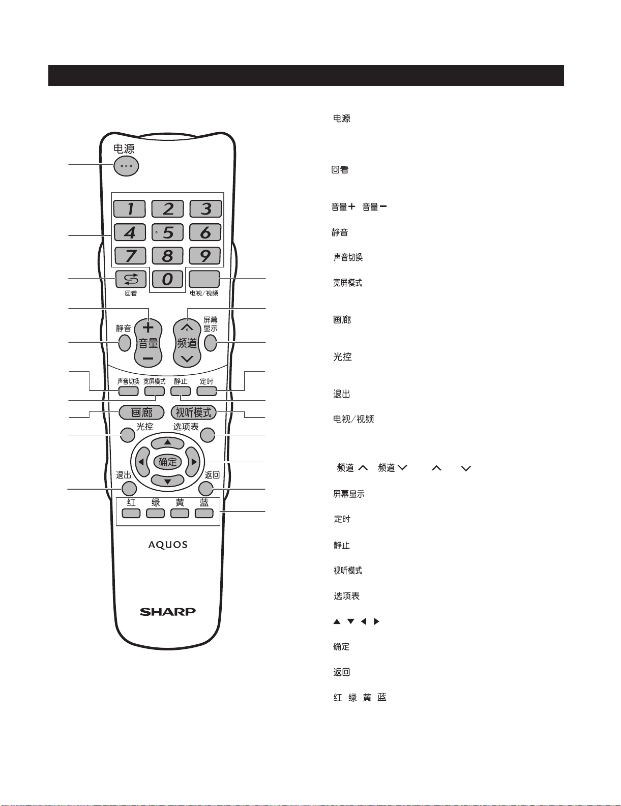
[2] OPERATION MANUAL
Remote control unit
LCD-52XS1A/LCD-65XS1A
1
2
3
4
5
6
7
8
9
10
11
12
13
14
15
16
17
18
19
20
1
2
3
4
5
6
7
8
9
10
11
12
13
14
15
16
17
18
19
20
(POWER)
To switch the power on and off.
0-9
Set the channel.
(FLASHBACK)
Press to return to the previous selected channel or
external input mode.
/
Set the volume.
(MUTE)
Mute the sound.
Select the sound multiplex mode.
Change the wide image mode.
(GALLERY)
Press to enter the Gallery Mode.
(OPC)
To switch the Optical Picture Control on and off.
(EXIT)
Turn off the On-Screen Display.
Select an input source. (TV, INPUT 1, INPUT 2,
INPUT 3, INPUT 4, INPUT 5, INPUT6, INPUT7
(PC), IrSS)
TV input mode: Select the channel.
Displays the channel or input information.
(SLEEP)
Set the Sleep timer.
(FREEZE)
Freeze a motion picture on the screen.
Select a video setting.
Display the menu screen.
/ / / (CURSOR)
Select a desired item on the setting screen.
(ENTER)
Execute a command.
(RETURN)
MENU mode: Return to the previous menu screen.
///
To enter the IrSS™ function.
(VOLUME +/ VOLUME -)
(MPX)
(WIDE MODE)
(INPUT)
/
(DISPLAY)
(AV MODE)
(MENU)
(CH /CH )
(RED/GREEN/YELLOW/BLUE)
1 – 2
Page 58

LCD-52XS1A/LCD-65XS1A
Part name
Display (Front view/Side view)
12345 6 9
Volume down ( )/ up ( ) buttons
1
Channel down ( )/up ( ) buttons
2
INPUT button
3
MENU button
4
POWER (On/Off) button
5
IrSS™ port
6
POWER indicator
7
SLEEP timer indicator
8
OPC indicator*
9
10
11
(Reset button)
USB terminal
* OPC: Optical Picture Control
78
AVC System (Front view/Rear view)
21 3 4 5 6 7
POWER button
1
POWER indicator
2
(Reset button)
3
4
5
6
WARNING
Excessive sound pressure from earphones and headphones can cause hearing loss.
•
Do not set the volume at a high level. Hearing experts advise against extended listening at high volume levels.
•
8 9 10
11 12
(INPUT 3) (HDMI) terminal
(INPUT 7) (PC) terminals
(INPUT 4) terminals
10
11
(Headphone jack)7
8
9
10
11
12
(INPUT 5) terminals
(INPUT 6) terminals
(REC OUTPUT terminals)
(Antenna terminal)
DC OUTPUT terminal
AVCSystem(Bottomview)
13
13
14
15
16
(INPUT 1) terminals (HDMI)
(INPUT 2) terminal (HDMI)
RS-232C terminal
14 15 16 17 18 19
(DIGITAL AUDIO
OUTPUT terminal)
17
18
19
Usually do not connect anything to
*
this terminal as it is reserved only for
service personnel.
Product label is on the bottom of the
AVC System.
1 – 3
(Service only terminal)*
(Display output terminal)
(AC INPUT terminal)
Page 59

LCD-52XS1A/LCD-65XS1A
Before turning on the main power
Preparing the Display
Make sure the Display is turned off before beginning work.
•
Before performing work, spread cushioning over the surface on which you will be laying the Display. This will
•
prevent it from being damaged.
Connecting the HDMI cable with the HDMI cable holder
HDMI cable
(supplied)
Speaker cable*
Press down on
1 Connect the
the upper hook
and remove the
rear terminal cover,
pulling towards
you.
NOTE
These are terminals for the speaker of the TV. Do not connect any other kind of cables.
*
•
Do not disconnect the speaker cable unless absolutely necessary. If you disconnect the speaker cable, confirm each colour of
the speaker plugs and speaker terminals (the order of the colour from left to right: red/black/white).
2 Affix the HDMI
HDMI cable to
the Display.
3
cable holder by
pressing down.
HDMI cable
holder
(supplied)
Handling and precautions with the wall-mounted Display
You can mount the Display on the wall using the optional AN-52AG8 or AN-65AG2 bracket.
•
For details, refer to the instructions supplied with the optional bracket.
•
CAUTION
•
This Display should be mounted on the wall only with the AN-52AG8 or AN-65AG2 (SHARP) wall
mount bracket. The use of other wall mount brackets may result in an unstable installation and may
cause serious injuries.
•
Installing the Liquid Crystal Television requires special skill that should only be performed by
qualified service personnel. Customers should not attempt to do the work themselves. SHARP bears
no responsibility for improper mounting or mounting that results in accident or injury.
Using an optional bracket to mount the Display
•
You can ask a qualified service personnel about using an optional AN-52AG8 or AN-65AG2 bracket to mount the Display to the wall
Carefully read the instructions that come with the bracket before beginning work.
•
Hanging on the wall
About setting the Display angle
AN-52AG8 or AN-65AG2 wall mount bracket.
(See the bracket instructions for details.)
You can check the centre of the TV
screen using the mark engraved
on the wall mount bracket when
mounting the Display on the wall.
LCD-52XS1A: The centre of the TV
screen is at mark “E” on the wall bracket.
LCD-65XS1A: The centre of the TV
screen is at mark “A” on the wall bracket.
Vertical mounting
AN-52AG8 or AN-65AG2
NOTE
Detach the cable clamps on the rear of the Display when using the optional mount bracket.•
1 – 4
Page 60

LCD-52XS1A/LCD-65XS1A
Setting the TV and antenna cables
Standard
DIN45325 plug
(IEC 169-2) 75
coaxial cable
Do not use excessive
force when inserting/
removing the HDMI
cable. The terminal or
cable may become
damaged.
Connecting the HDMI cable with the
HDMI cable (supplied)
fixture
12 3
Connect the HDMI cable
1 Attach the parts of the fixture
to the DISPLAY OUTPUT
terminal on the AVC System.
NOTE
The POWER indicator of the AVC System lights up when the main power is turned on after connecting the Display and AVC System using the
•
supplied HDMI cable.
The HDMI cable should be firmly connected. Failure to do so will loosen the cable and cause a contact failure when moving the AVC System.
•
This can cause result in an error message appearing on the screen without a visible picture.
2 Insert the tab for the fixture
to the HDMI cable, pushing
the tab upward.
The fixture
anchor hole
3
into the fixture anchor hole on
the AVC System.
Handling the AVC System
CAUTION
Do not put a VCR or other device on top of the AVC System.
•
Keep enough space above and to the sides of the AVC
•
System.
Do not block the ventilation openings on the top and left side or
•
the exhaust fan on the right side.
Do not spread a thick cloth beneath the AVC System or cover it with one, as this can cause overheating and result in
•
malfunction.
5cm
5cm 5cm
1 – 5
Page 61

[3] DIMENSIONS
LCD-52XS1A/LCD-65XS1A
(LCD-52XS1A)
765113
878
400
200
1156
1243
1075
400.0
652
Unit: mm
511
47.1
22.8
(LCD-65XS1A)
933113
1046
314
400
1432.3
1528
1312
400
60.4
807.4
598
47.1
22.8
1 – 6
60.4
Page 62

LCD-52XS1A/LCD-65XS1A
2
9
LCD-52XS1A
CHAPTER 2. REMOVING OF MAJOR PARTS
Service Manual
[1] REMOVING OF MAJOR PARTS (LCD-52XS1A)
1. Removing of Speaker Box Ass'y and Cabinet B Ass'y
1. Remove the 4 lock screws and detach the Speaker Angle Cover Ass'y .
2. Remove the 4 lock screws and detach the Speaker Box Ass'y
3. Detach the AC Cover Top . Remove the 2 lock screws and AC Cover Bottom .
1
3
4
5
6
4. Detach the Terminal Cover , Bus-Cone Cover and 2 VESA Caps .
5. Remove the 13 lock screws , 6 lock screws , 4 lock screws , Reinforcement panel , and 20 lock screws . Detach the Cabinet B
Ass'y.
7
10
8
11
12
13
14
Cabinet B Ass'y
VESA Cap
9
13
11
2
7
8
12
3
11
11
14
10
Bus-Cone Cover
Terminal Cover
Speaker Angle
Cover Ass'y
5
1
AC Cover Top
AC Cover Bottom
4
6
2 – 1
Speaker Box Ass'y
Page 63

LCD-52XS1A/LCD-65XS1A
2. Removing of R/C, LED Unit and each shield.
1. Disconnect the RA connector from R/C, LED Unit.
2. Remove the 2 lock screws and detach the R/C, LED Unit.
3. Remove the 2 lock screws and 9 lock screws . Detach the IF Radiator Shield Ass'y.
4. Remove the 1 lock screw and 7 lock screws . Detach the A3C Radiator Shield Ass'y.
5. Remove the 12 lock screws and detach the Chassis Tray Shield R.
6. Remove the 1 lock screw and detach the Barrier Sheet . Remove the 11 lock screws and detach Chassis Tray Shield L Ass'y.
1
2
4
6
7
3
5
8
9
6
3
2
2
IF Radiator
Shield Ass'y
Chassis Tray
Shield R
[RA]
R/C, LED Unit
[RA]
1
Chassis Tray
Shield L Ass'y
4
A3C Radiator
Shield Ass'y
9
7
8
Barrier Sheet
5
2 – 2
Page 64

LCD-52XS1A/LCD-65XS1A
3. Removing of connectors
1. Disconnect the following connectors from IF Unit. (LE, PD, PE, LW, KM, LB, FR, SP, US)
2. Disconnect the following connectors from USB Unit. (US)
3. Disconnect the following connectors from SP-T Unit. (SP)
4. Disconnect the following connectors from A3C LCD T-CON Unit. (RA, LW, LB, LC)
5. Disconnect the following connectors from MAIN POWER Unit. (PD, PI, PE, PS1, ACM)
6. Disconnect the following connectors from SUB-1 POWER Unit. (PS1, PS2, LA1, AC1, ACM)
7. Disconnect the following connectors from SUB-2 POWER Unit. (PS2, LA2, AC1, AC2)
8. Disconnect the AC2 connector from AC INLET Unit.
9. Disconnect the KM connector from KEY Unit.
10.Disconnect the AC connector from DC OUTPUT Unit.
MAIN POWER Unit
IF Unit
USB Unit
SP-T Unit
[PI]
[LE]
[SP]
[US]
[AC]
DC OUTPUT Unit
SUB-1 POWER Unit
[PI] [PE]
[PD]
[PS1]
[ACM]
[ACM]
[RA]
[LW]
[LB]
[LC]
[KM]
KEY Unit
[LA1]
[AC1]
[PS2]
[PS2]
[LA2]
[AC1]
[AC2]
A3C LCD
T-CON Unit
[LA1]
[LA2]
SUB-2
POWER Unit
[AC2]
AC INLET Unit
IF Unit
[US]
[LE]
[PD]
[PE]
[LW]
[FR]
[LB]
[KM]
[SP]
2 – 3
Page 65

4. Removing of MAIN POWER Unit, SUB-1 POWER Unit and SUB-2 POWER Unit
1. Remove the 15 lock screws .
1
LCD-52XS1A/LCD-65XS1A
2. Detach the Power Unit Fix Angle Top Ass'y , Power Unit Fix Angle Bottom Ass'y and Power Unit Fix Angle .
3. Remove the 12 lock screws . Detach the MAIN POWER Unit, SUB-1 POWER Unit and SUB-2 POWER Unit.
5
2
3
4
SUB-1 POWER Unit
5
MAIN POWER Unit
SUB-2 POWER Unit
Power Unit Fix Angle
Top Ass'y
2
1
4
Power Unit
Fix Angle
3
Power Unit Fix Angle
Bottom Ass'y
2 – 4
Page 66

LCD-52XS1A/LCD-65XS1A
5. Removing of USB Unit, SP-T Unit, DC OUTPUT Unit, IF Unit and AC INLET Unit
1. Remove the 1 lock screw and USB Fix Angle . Remove the 1 lock screw and detach the USB Unit from USB Cover Holder.
2. Remove the 2 lock screws and detach the SP-T Unit.
3. Detach the DC OUTPUT Unit from Jack Cover.
4. Remove the 6 lock screws and detach the IF Unit.
5. Remove the 4 lock screws and detach the AC INLET Unit.
1
4
5
6
2
3
5
IF Unit
USB Fix Angle
2
1
3
USB Unit
SP-T Unit
USB Cover
Holder
Jack Cover
DC OUTPUT
Unit
6
4
AC INLET Unit
2 – 5
Page 67

6. Removing of KEY Unit and LED Backlight Module
1. Remove the 2 lock screws and detach the KEY Unit.
2. Remove the 4 lock screws and detach the LED Backlight Module from Cabinet A Ass'y.
1
2
LED Backlight Module
LCD-52XS1A/LCD-65XS1A
2
2
1
KEY Unit
2 – 6
Page 68

LCD-52XS1A/LCD-65XS1A
3
7. Removing of LCD Panel Module
1. Remove the 10 lock screws , 11 lock screws and 21 lock screws . Detach the 52' Full-HD LCD Panel module.
2. Detach the LED Backlight Module, Lens Sheet, Diffusion Sheet, BEF Sheet and D-BEF Sheet.
1
2
LED Backlight Module
Diffusion Sheet
D-BEF Sheet
1
2
3
Lens Sheet
BEF Sheet
52' Full-HD LCD Panel module
2 – 7
Page 69
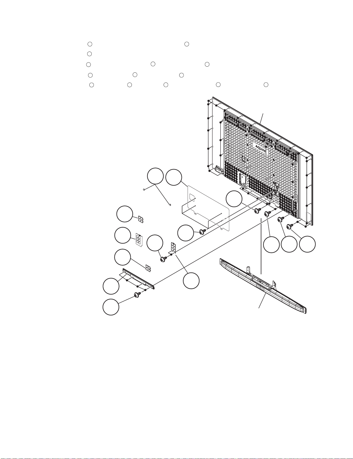
[2] REMOVING OF MAJOR PARTS (LCD-65XS1A)
2
9
1. Removing of Speaker Box Ass'y and Cabinet B Ass'y
1. Remove the 4 lock screws and detach the Speaker Angle Cover Ass'y .
2. Remove the 4 lock screws and detach the Speaker Box Ass'y
3. Detach the AC Cover Top . Remove the 2 lock screws and AC Cover Bottom .
1
3
4
5
6
LCD-52XS1A/LCD-65XS1A
4. Detach the Terminal Cover , Bus-Cone Cover and 2 VESA Caps .
5. Remove the 18 lock screws , 5 lock screws , 4 lock screws , Reinforcement panel and 24 lock screws . Detach the Cabinet B Ass'y.
7
10
8
11
12
13
14
Cabinet B Ass'y
VESA Cap
9
13
3
Bus-Cone Cover
Terminal Cover
7
8
5
12
11
1410
AC Cover Top
Speaker Angle
Cover Ass'y
4
6
2
AC Cover Bottom
1
Speaker Box Ass'y
2 – 8
Page 70

LCD-52XS1A/LCD-65XS1A
2. Removing of R/C, LED Unit and each shield.
1. Disconnect the RA connector from R/C, LED Unit.
2. Remove the 2 lock screws and detach the R/C, LED Unit.
1
3. Remove the 2 lock screws and 9 lock screws . Detach the IF Radiator Shield Ass'y.
4. Remove the 1 lock screw and 7 lock screws . Detach the A3C Radiator Shield Ass'y.
5. Remove the 1 lock screw and detach the Barrier Sheet . Remove the 22 lock screws and detach the Chassis Tray Shield R.
6. Remove the 1 lock screw and detach the Barrier Sheet . Remove the 23 lock screws and detach Chassis Tray Shield L Ass'y.
7
6
2
4
6
9
Barrier Sheet
Chassis Tray
Shield R
8
3
5
7
10
8
11
11
Chassis Tray
Shield L Ass'y
9
10
Barrier Sheet
3
2
R/C, LED Unit
IF Radiator Shield Ass'y
[RA]
[RA]
5
1
A3C Radiator Shield Ass'y
4
2 – 9
Page 71

3. Removing of connectors
1. Disconnect the following connectors from IF Unit. (LE, PD, PE, LW, FR, LB, KM, US, SP, RA, SD)
2. Disconnect the following connectors from USB Unit. (US)
3. Disconnect the following connectors from SP-T Unit. (SP)
4. Disconnect the following connectors from A3C LCD T-CON Unit. (LW, LB, FR)
5. Disconnect the following connectors from MAIN POWER Unit. (PD, PI, PE, PS1, PS3, ACM, AC3)
6. Disconnect the following connectors from SUB-1 POWER Unit. (PS1, PS2, LA1, AC1, ACM)
7. Disconnect the following connectors from SUB-2 POWER Unit. (PS2, LA2, AC1, AC2)
8. Disconnect the following connectors from SUB-3 POWER Unit. (PS3, LA3, AC3)
9. Disconnect the AC2 connector from AC INLET Unit.
10.Disconnect the KM connector from KEY Unit.
11.Disconnect the AC connector from DC OUTPUT Unit.
LCD-52XS1A/LCD-65XS1A
SUB-3 POWER Unit
IF Unit
USB Unit
[US]
MAIN POWER Unit
[PI]
[LE]
[PS3]
[AC3]
[SP]
[AC]
OUTPUT Unit
[PS3][LA3]
[PI] [PE]
[PD]
[AC3]
[KM]
SUB-1 POWER Unit
[PS2]
[PS1]
[ACM] [AC1]
[ACM]
[LW]
[LB]
[FR]
KEY UnitSP-T Unit DC
SUB-2 POWER Unit
[LA1]
[LA2]
[PS2]
[AC1]
[AC2]
T-CON Unit
[LA3]
[LA1]
[LA2]
[AC2]
AC INLET UnitA3C LCD
IF Unit
[US]
[SD]
[RA]
[PD] [PE]
[LE]
[LW]
[FR]
[LB]
[KM]
[SP]
2 – 10
Page 72

LCD-52XS1A/LCD-65XS1A
4. Removing of MAIN POWER Unit, SUB-1 POWER Unit and SUB-2 POWER Unit
1. Remove the 8 lock screws .
2. Detach the Power Unit Fix Angle Top Ass'y , Power Unit Fix Angle Bottom Ass'y and Power Unit Fix Angle .
3. Remove the 12 lock screws . Detach the MAIN POWER Unit, SUB-1 POWER Unit and SUB-2 POWER Unit.
1
2
5
3
4
MAIN POWER Unit
SUB-1 POWER Unit
5
SUB-2 POWER Unit
1
Power Unit
Fix Angle Top Ass'y
2
Power Unit
4
Fix Angle
3
Power Unit
Fix Angle Bottom Ass'y
2 – 11
Page 73

LCD-52XS1A/LCD-65XS1A
5. Removing of USB Unit, SUB-3 POWER Unit, SP-T Unit, DC OUTPUT Unit, IF Unit and AC INLET Unit
1. Remove the 1 lock screw and USB Fix Angle . Remove the 1 lock screw and detach the USB Unit from USB Cover Holder.
2. Remove the 4 lock screws and detach the SUB-3 POWER Unit.
1
4
2
3
3. Remove the 4 lock screws and detach the AC INLET Unit.
4. Remove the 2 lock screws and detach the SP-T Unit.
5. Detach the DC OUTPUT Unit from Jack Cover.
6. Remove the 6 lock screws and detach the IF Unit.
5
6
7
4
SUB-3 POWER Unit
7
5
IF Unit
USB Fix Angle
2
1
3
SP-T Unit
USB Cover Holder
USB Unit
AC INLET Unit
Jack Cover
DC OUTPUT Unit
6
2 – 12
Page 74

LCD-52XS1A/LCD-65XS1A
6. Removing of KEY Unit and LED Backlight Module
1. Remove the 2 lock screws and detach the KEY Unit.
2. Remove the 4 lock screws and detach the LED Backlight Module from Cabinet A Ass'y.
1
2
LED Backlight Module
2
2
KEY Unit
1
2 – 13
Page 75

7. Removing of LCD Panel Module
3
LCD-52XS1A/LCD-65XS1A
1. Remove the 10 lock screws , 13 lock screws and 22 lock screws . Detach the 65' Full-HD LCD Panel module.
2. Detach the LED Backlight Module, Lens Sheet, Diffusion Sheet, BEF Sheet and D-BEF Sheet.
1
2
LED Backlight Module
Diffusion Sheet
D-BEF Sheet
1
2
3
Lens Sheet
BEF Sheet
65' Full-HD LCD Panel module
2 – 14
Page 76

LCD-52XS1A/LCD-65XS1A
LCD-52XS1A
CHAPTER 3. ADJUSTMENT
Service Manual
[1] ADJUSTMENT PROCEDURE
1. Adjustment method after PWB and/or IC replacement due to repair
The unit is set to the optimum at the time of shipment from the factory. If any value should become improper or any adjustment is necessary due to
the part replacement, make an adjustment according to the following procedure.
1. Prepare the following parts of writing software when you exchange IC7002 in the IF unit on the monitor side.
Applicable parts: RH-iXC331WJN9Q
NOTE: Caution when replacing ICs in the main unit (IC6001)
The above ICs are EEPROMs storing the EDID data of HDMI and the sub microcomputer.
To change applicable parts, it is necessary to write in the data of EDID.
It is possible to write from the microcomputer in the IF board, and execute "EDID WRITE" on the monitor step mode page, please with the fol-
lowing harness connected.
52 inches LB harness : QCNW-H636WJQZ
KM harness : QCNW-H713WJQZ
65 inches LB harness : QCNW-H623WJQZ
KM harness : QCNW-H710WJQZ
2. After replacing the LCD panel or LCD control PWB, adjust the COMB-BIAS Adjustment.
Refer to the [4]-1-1 item.
3. After replacing the LCD panel or LCD control PWB by 65 type, also adjust the upper and lower brightness difference adjustment.
Refer to the [4]-1-2 item.
[2] Entering and exiting the adjustment process mode
1. Entering and exiting the adjustment process mode
1. Pull out the AC plug on the display side under operation from the outlet.
2. While holding down the “VOL (+)” and “P(V)” keys on the set at once, Put the AC code. (It changes to the monitor inspection m ode.)
3. While holding down the “VOL (–)” and “P(V)” keys on the set at once, It enters the monitor adjustment process mode.
Multiple lines of blue character string appearing on the screen indicate that the set is now in the adjustment Process mode.
If you fail to enter the adjustment process mode (the display is the same as normal startup), retry the procedure. (Another procedure)
4. To exit the adjustment process mode after the adjustment is done, unplug the AC power cord to force off the power. (or please press the MAIN
POWER key and turn off a power supply).
(When the power is turned off with the remote controller, once unplug the AC power cord and plug it in again. In this case, wait 20 seconds or so
before plugging.)
CAUTION: Use due care in handling the information described here lest the users should know how to enter the adjustment process mode.
If the settings are tampered with in this mode, unrecoverable system damage may result.
3 – 1
Page 77

LCD-52XS1A/LCD-65XS1A
2. Remote controller key operation in adjustment process mode.
1. key operation
Remote controller key Main unit key Remote controller key Main unit key Function
CH ( / )
VOL (+/-) VOL (+/-) Changing a selected item setting (+1/-1)
Cursor ( / )
Cursor ( / )
OK — Executing a function/ canceling a test pattern .
CHP1-CHP6 W/B adjustment check. It is a BETA setup about the gamma value in each adjustment point. It is off
Page specification (1-10item) It jumps to the pressed page. The cursor position after it moves selects the first line
Line specification (1-6line) The cursor moves to the pressed line.
Screen display — It is considered as monitor process mode OSD all OFF . It displays it again by another key pressing.
Input mode is switched automatically when relevant adjustment is started so far as the necessary input signal is available.
CH ( / )
— Turning a page (PREVIOUS / NEXT)
— Changing a selected line setting (+10/-10)
3. Description of display
(1) Present㵘page / number of total pages (3)Destination display
(2) Page present title (4) Model size
Moving an item (line) by one (UP/DOWN)
again in the same key pressing. *Other key input is invalid in the on condition. However , it shall be
effective when other Point keys (CHP1-CHP6) are pressed.
1/ 46 [INFO] INPUT1 AUTO CHINA 65A_UNDER[0]
MONITOR MAIN Version 1.10 (E 2008/09/03 1)
NONITOR BOOT Version 1.01
Monitor SUB Version 1.05
FRC Version 71716531
LED A/MAIN/SUB version 0808236501/1.0.0/1.0.0
CPLD/FPGA Version a3 / 46
EQ DATA CHECKSUM ROM
LAMP ERROR 0
MONITOR SUB ERR CAUSE 00 00 00 00
NORMAL STANDBY CAUSE 0
ERROR STANDBY CAUSE 1) 0 2) 0 3 ) 0
(5) Item name 㩿㪍㪀㩷㪧㪸㫉㪸㫄㪼㫋㪼㫉
No. Description Display specification
(1) Present page/number of total
pages
(2) Page present title Max. 15 char “[“ “]”.
(3) Destination display ASIA/CHINA/HONG KONG
(4) Model size 65/52
(5) Item name Max. 30 char
(6) Parameter Max. 60 char
2char/2char Decimal Number mark.
0H 0M 0H 0M 0H 0M
4) 0 5) 0
0H 0M 0H 0M
Process menu header
3 – 2
Page 78

LCD-52XS1A/LCD-65XS1A
[3] Monitor adjustment process mode menu
The character string in brackets [***] appear as a page title in the adjustment process menu header.
Page Line Item Description Remarks (adjustment detail, etc.)
1/46 [INFO]
1 MONITOR MAIN Version 1.10(W2008/09/03 1) Monitor Main software version
2 MONITOR BOOT Version 1.01 Monitor BOOT Version.
3 MONITOR SUB Version 1.05 Monitor sub software version
4 FRC Version 71716531 FRC Version
5 LED A/MAIN/SUB version 0808236501/1.0.0/1.0.0 A3C,LEDTCON software, LEDTCON FPGA Version
6 CPLD/FPGA Version a3 / 46 CPLD/FPGA Version.
7 EQ DATA CHECKSUM ROM Audio data checksum.
8 LAMP ERROR 0 Number of termination due to lamp error.
9 MONITOR SUB ERR CAUSE 00 00 00 00 Monitor error standby cause.
10 NORMAL STANDBY CAUSE 0 Situation that became standby at the end.
(Excluding the error)
11 ERROR STANDBY CAUSE 1) 0 0H 0M Error standby cause Total operating time before error.
2) 0 0H 0M (5 times history)
3) 0 0H 0M
4) 0 0H 0M
5) 0 0H 0M
2/46 [INIT]
1 INDUSTRY INIT OFF Initialization to factory settings execution.
2 INDUSTRY INIT(-Hotel) OFF Initialization to factory settings execution.
(Hotel mode is excluded)
3 HOTEL MODE OFF Hotel mode ON/OFF setting
4 Center Acutime **H **M Main integrated operating time (reset by the factory setting)
5 RESET OFF Main integrated operating time reset.
6 Backlight Acutime **H **M Backlight accumulative operating time (not reset by factory setting)
7 RESET OFF Backlight accumulative operating times reset.
8 LAMP ERROR RESET OFF The number of times which carried out power supply OFF in the
lamp error is set to 0.
9 VIC XPOS 0 Disclosure
10 VIC YPOS 0 Disclosure
11 VIC BUFFER CAPTURE Disclosure
12 VIC SIGNAL TYPE MAIN Disclosure
13 VIC READ OFF Disclosure
3/46 [PANELADJ]
1 VCOM ADJ 45 Common bias adjustment
2 LCD LUMA ADJ NOT SUPPORT Upper and lower brightness difference adjustment
3 HDMI EDID WRITE Enter Execute HDMI EDID Data write
4 HDMI CEC TEST Enter Disclosure
5 INSPECT USB TERM Enter Disclosure
6 IRSS TEST Enter Disclosure
7 FDFB ADJ Enter Disclosure
8 LED TCON OPEN ERROR 0 Disclosure
9 MAIN TEMPERATURE 67 Disclosure
10 MONIDATA READ[TEMP/OPC] OFF Disclosure
11 GAMMA PATTERN MODE LCD ADJ Disclosure
4/46 [FR DDRTEST]
1 DDRA TEST1 Enter Execute DDRA test 1
2 DDRA TEST2 Enter Execute DDRA test 2
3 DDRB TEST1 Enter Execute DDRA test 1
4 DDRB TEST2 Enter Execute DDRA test 2
5 DDRB TEST3 Enter Execute DDRA test 3
6 FRC ON/OFF Enter Execute F RC ON/OFF
7 FRA DDRA BIST Enter Execute FRA DDRA BIST
8 FRA DDRB BIST Enter Execute FRA DDRB BIST
9 POSTFILTER ON/OFF ON Execute POSTFILTER ON/OFF
3 – 3
Page 79

LCD-52XS1A/LCD-65XS1A
Page Line Item Description Remarks (adjustment detail, etc.)
5/46 [GAMMA IN]
1 MONITOR GAMMA IN 1 102 Disclosure
2 MONITOR GAMMA IN 2 128 Disclosure
3 MONITOR GAMMA IN 3 153 Disclosure
4 MONITOR GAMMA IN 4 179 Disclosure
5 MONITOR GAMMA IN 5 204 Disclosure
6 MONITOR GAMMA IN 6 230 Disclosure
7 MONITOR WRITE OFF Disclosure
8 MONITOR RESET OFF Disclosure
6/46 [GAMMA R1]
1 MONITOR GAMMA R 1 1632 Disclosure
2 MONITOR GAMMA G 1 1632 Disclosure
3 MONITOR GAMMA B 1 1632 Disclosure
4 MONITOR GAMMA R 2 2048 Disclosure
5 MONITOR GAMMA G 2 2048 Disclosure
6 MONITOR GAMMA B 2 2048 Disclosure
7 MONITOR GAMMA R 3 2448 Disclosure
8 MONITOR GAMMA G 3 2448 Disclosure
9 MONITOR GAMMA B 3 2488 Disclosure
10 GAMMA WRITE OFF Disclosure
11 GAMMA RESET OFF Disclosure
7/46 [GAMMA R4]
1 MONITOR GAMMA R 4 2864 Disclosure
2 MONITOR GAMMA G 4 2864 Disclosure
3 MONITOR GAMMA B 4 2864 Disclosure
4 MONITOR GAMMA R 5 3264 Disclosure
5 MONITOR GAMMA G 5 3264 Disclosure
6 MONITOR GAMMA B 5 3264 Disclosure
7 MONITOR GAMMA R 6 3680 Disclosure
8 MONITOR GAMMA G 6 3680 Disclosure
9 MONITOR GAMMA B 6 3680 Disclosure
10 GAMMA WRITE OFF Disclosure
11 GAMMA RESET OFF Disclosure
8/46 [LED 1]
1 LED Lo ADJ OFF Disclosure
2 LED Hi ADJ OFF Disclosure
3 LED GAMMA IN Point 64 Disclosure
4 LED GAMMA Lo R 64 Disclosure
5 LED GAMMA Lo G 64 Disclosure
6 LED GAMMA Lo B 64 Disclosure
7 LED GAMMA Hi R 4095 Disclosure
8 LED GAMMA Hi G 4095 Disclosure
9 LED GAMMA Hi B 4095 Disclosure
9/46 [LED 2 (STD)]
1 LED S LO ADJ OFF Disclosure
2 LED S HI ADJ OFF Disclosure
3 LED S GAMMA IN POINT 64 Disclosure
4 LED S GAMMA LO R 64 Disclosure
5 LED S GAMMA LO G 64 Disclosure
6 LED S GAMMA LO B 64 Disclosure
7 LED S GAMMA HI R 4095 Disclosure
8 LED S GAMMA HI G 4095 Disclosure
9 LED S GAMMA HI B 4095 Disclosure
10/46 [LED 3 (WALL)]
1 LED W LO ADJ OFF Disclosure
2 LED W HI ADJ OFF Disclosure
3 LED W GAMMA IN POINT 64 Disclosure
4 LED W GAMMA LO R 64 Disclosure
5 LED W GAMMA LO G 64 Disclosure
6 LED W GAMMA LO B 64 Disclosure
7 LED W GAMMA HI R 4095 Disclosure
8 LED W GAMMA HI G 4095 Disclosure
9 LED W GAMMA HI B 4095 Disclosure
3 – 4
Page 80

LCD-52XS1A/LCD-65XS1A
Page Line Item Description Remarks (adjustment detail, etc.)
11/46 [G CO POS]
1 MODE SELECT FACTORY Disclosure
2 POS SELECT WB IN Disclosure
3 POS MIN 0 Disclosure
4 POS MID1 Disclosure
5 POS MID2 Disclosure
6 POS MID3 Disclosure
7 POS MID4 Disclosure
8 POS MID5 Disclosure
9 POS MID6 Disclosure
10 POS MAX Disclosure
12/46 [G CO CD]
1 CD MIN Disclosure
2 CD MID1 Disclosure
3 CD MID2 Disclosure
4 CD MID3 Disclosure
5 CD MID4 Disclosure
6 CD MID5 Disclosure
7 CD MID6 Disclosure
8 CD MAX Disclosure
13/46 [G CO VAL]
1 CALC OFF Disclosure
2 RESET OFF Disclosure
3 VAL1 100 Disclosure
4 VAL2 100 Disclosure
5 VAL3 100 Disclosure
6 VAL4 100 Disclosure
7 VAL5 100 Disclosure
8 VAL6 100 Disclosure
14/46 [ACTIVEBL 1]
1 ABL TEST MODE Enter Disclosure
2 PRINT DEBUG OFF Disclosure
15/46 [TM_STATUS]
1 TM_STATUS_UPDATE Enter Disclosure
2 RX_LEVEL_NOW OFF Disclosure
3 RX_LEVEL_MIN Disclosure
4 RX_LINK_STATE Disclosure
5 RX_SELECTION_CHANNEL Disclosure
6 RX_TRANSMIT_POWER Disclosure
7 RX_DOWNLINK_QUALITY Disclosure
8 RX_AUDIO_BER Disclosure
9 RX_ERROR_CORRECTION Disclosure
10 TX_TRANSMIT_POWER Disclosure
16/46 [TM_INFO]
1 RX_SOFT_VERSION_IO Disclosure
2 RX_SOFT_VERSION_RF Disclosure
3 TX_SOFT_VERSION_IO Disclosure
4 TX_SOFT_VERSION_RF Disclosure
5 RX_SINK_DEVICE_ID Disclosure
6 RX_SOURCE_DEVICE_ID Disclosure
7 RX_REGION Disclosure
8 TX_REGION Disclosure
9 TX_AFS_TYPE Disclosure
10 TX_AFS_MODE Disclosure
11 TX_TPC_MODE Disclosure
3 – 5
Page 81

LCD-52XS1A/LCD-65XS1A
Page Line Item Description Remarks (adjustment detail, etc.)
17/46 [TM_RX_ANT]
1 TM_RX_ANT_INFO_UPDATE Enter Disclosure
2 RX_RECEIVE_POWER 1 Disclosure
3 RX_RECEIVE_POWER 2 Disclosure
4 RX_RECEIVE_POWER 3 Disclosure
5 RX_RECEIVE_POWER 4 Disclosure
6 RX_RECEIVE_POWER 5 Disclosure
7 RX_SNR_AVR_MIN_MAX 1 Disclosure
8 RX_SNR_AVR_MIN_MAX 2 Disclosure
9 RX_SNR_AVR_MIN_MAX 3 Disclosure
10 RX_SNR_AVR_MIN_MAX 4 Disclosure
11 RX_SNR_AVR_MIN_MAX 5 Disclosure
18/46 [TM_RX_CS]
1 TM_RX_CS_INFO_UPDATE Enter Disclosure
2 RX_CS 01 Disclosure
3 RX_CS 02 Disclosure
4 RX_CS 03 Disclosure
5 RX_CS 04 Disclosure
6 RX_CS 05 Disclosure
7 RX_CS 06 Disclosure
8 RX_CS 07 Disclosure
9 RX_CS 08 Disclosure
10 RX_CS 09 Disclosure
19/46 [TM_TX_CS]
1 TM_TX_CS_INFO_UPDATE Enter Disclosure
2 TX_CS 01 Disclosure
3 TX_CS 02 Disclosure
4 TX_CS 03 Disclosure
5 TX_CS 04 Disclosure
6 TX_CS 05 Disclosure
7 TX_CS 06 Disclosure
8 TX_CS 07 Disclosure
9 TX_CS 08 Disclosure
10 TX_CS 09 Disclosure
20/46 [SOUND 1]
1 AUTO_SWITCH ROM Disclosure
2 FLAT_MODE Disclosure
3 EEP_STATUS_INIT Disclosure
4 SP_OUTPUT_MODE Disclosure
5 LIP_SYNC_A Disclosure
6 INPUT_TRIM Disclosure
7 OUTPUT_TRIM_LR Disclosure
8 OUTPUT_TRIM_SW Disclosure
9 SUB_VOLUME_SP Disclosure
10 SUB_VOLUME_SW Disclosure
21/46 [SOUND 2]
1 SUB_VOLUME_ROOM_LIVING Disclosure
2 SUB_VOLUME_ROOM_BED Disclosure
3 SUB_VOLUME_ROOM_
JAPANESE
4 SUB_VOLUME_ROOM_
CORNER
5 SUB_VOLUME_ROOM_WALL Disclosure
6 SUB_VOLUME_ROOM_WALL_
HUNG
7 SUB_VOLUME_AV_STANDARD Disclosure
8 SUB_VOLUME_AV_DYNAMIC Disclosure
9 SUB_VOLUME_AV_MOVIE Disclosure
10 SUB_VOLUME_AV_NEWS Disclosure
11 MATRIX_LR Disclosure
12 MATRIX_SW Disclosure
Disclosure
Disclosure
Disclosure
3 – 6
Page 82

LCD-52XS1A/LCD-65XS1A
Page Line Item Description Remarks (adjustment detail, etc.)
22/46 [SOUND 3]
1 PEQ_F1 Disclosure
2 PEQ_Q1 Disclosure
3 PEQ_GAIN1 Disclosure
4 PEQ_F2 Disclosure
5 PEQ_Q2 Disclosure
6 PEQ_GAIN2 Disclosure
7 PEQ_F3 Disclosure
8 PEQ_Q3 Disclosure
9 PEQ_GAIN3 Disclosure
10 PEQ_F4 Disclosure
11 PEQ_Q4 Disclosure
12 PEQ_GAIN4 Disclosure
23/46 [SOUND 4]
1 PEQ_F5 ROM Disclosure
2 PEQ_Q5 Disclosure
3 PEQ_GAIN5 Disclosure
4 PEQ_F6 Disclosure
5 PEQ_Q6 Disclosure
6 PEQ_GAIN6 Disclosure
7 PEQ_F7 Disclosure
8 PEQ_Q7 Disclosure
9 PEQ_GAIN7 Disclosure
10 PEQ_F8 Disclosure
11 PEQ_Q8 Disclosure
12 PEQ_GAIN8 Disclosure
24/46 [SOUND 5]
1 PEQ_F9 Disclosure
2 PEQ_Q9 Disclosure
3 PEQ_GAIN9 Disclosure
4 PEQ_F10 Disclosure
5 PEQ_Q10 Disclosure
6 PEQ_GAIN10 Disclosure
7 SW_PEQ_F1 Disclosure
8 SW_PEQ_Q1 Disclosure
9 SW_PEQ_GAIN1 Disclosure
10 SW_PEQ_F2 Disclosure
11 SW_PEQ_Q2 Disclosure
12 SW_PEQ_GAIN2 Disclosur e
25/46 [SOUND 6]
1 SW_PEQ_F3 Disclosure
2 SW_PEQ_Q3 Disclosure
3 SW_PEQ_GAIN3 Disclosure
4 SW_PEQ_F4 Disclosure
5 SW_PEQ_Q4 Disclosure
6 SW_PEQ_GAIN4 Disclosure
7 SW_PEQ_F5 Disclosure
8 SW_PEQ_Q5 Disclosure
9 SW_PEQ_GAIN5 Disclosure
10 SW_PEQ_F6 Disclosure
11 SW_PEQ_Q6 Disclosure
12 SW_PEQ_GAIN6 Disclosur e
26/46 [SOUND 7]
1 SRS_INPUT_GAIN Disclosure
2 SRS_OUTPUT_GAIN Disclosure
3 SRS_BYPASS_GAIN Disclosure
4 SRS_DIALOG_CLARITY_
CONTROL
5 SRS_TRUBASS_CONTROL Disclosure
6 SRS_TRUBASS_SPEAKERSIZE Disclosure
7 SRS_SURROUND_LEVEL_
CONTROL
Disclosure
Disclosure
3 – 7
Page 83

LCD-52XS1A/LCD-65XS1A
Page Line Item Description Remarks (adjustment detail, etc.)
27/46 [SOUND 8]
1 HPF_LR Disclosure
2 HPF_SW Disclosure
3 DRC_LR_LPF Disclosure
4 DRC_LR_HPF Disclosure
5 DRC_LR_LEVEL_L Disclosure
6 DRC_LR_LEVEL_H Disclosure
7 DRC_SW_LEVEL Disclosure
8 DRC_TIME_PATTERN Disclosure
28/46 [SOUND 9]
1 CLIPPER_LEVEL_LR Disclosure
2 CLIPPER_LEVEL_LR Disclosure
3 RESERVED1 Disclosure
4 RESERVED2 Disclosure
5 RESERVED3 Disclosure
6 RESERVED4 Disclosure
7 RESERVED5 Disclosure
8 RESERVED6 Disclosure
9 RESERVED7 Disclosure
10 RESERVED8 Disclosure
11 RESERVED9 Disclosure
12 RESERVED10 Disclosure
29/46 [M PWM]
1 PANEL SELECT ROM Disclosure
2 PWM Disclosure
3 PWM FREQ Disclosure
4 PWM DUTY Disclosure
5 OSC FREQ Disclosure
6 OSC DUTY Disclosure
30/46 [M OPC1]
1 OPC LDUTY 0 Disclosure
2 OPC LDUTY 1 Disclosure
3 OPC LDUTY 2 Disclosure
4 OPC LDUTY 3 Disclosure
5 OPC LDUTY 4 Disclosure
6 OPC LDUTY 5 Disclosure
7 OPC LDUTY 6 Disclosure
8 OPC LDUTY 7 Disclosure
9 OPC LDUTY 8 Disclosure
10 OPC LDUTY 9 Disclosure
11 OPC LDUTY 10 Disclosure
12 OPC LDUTY 11 Disclosure
31/46 [M OPC2]
1 OPC LDUTY 12 Disclosure
2 OPC LDUTY 13 Disclosure
3 OPC LDUTY 14 Disclosure
4 OPC LDUTY 15 Disclosure
5 OPC LDUTY 16 Disclosure
6 OPC LDUTY 17 Disclosure
7 OPC LDUTY 18 Disclosure
8 OPC LDUTY 19 Disclosure
9 OPC LDUTY 20 Disclosure
10 OPC LDUTY 21 Disclosure
11 OPC LDUTY 22 Disclosure
3 – 8
Page 84

LCD-52XS1A/LCD-65XS1A
Page Line Item Description Remarks (adjustment detail, etc.)
32/46 [M OPC3]
1 OPC LDUTY 23 Disclosure
2 OPC LDUTY 24 Disclosure
3 OPC LDUTY 25 Disclosure
4 OPC LDUTY 26 Disclosure
5 OPC LDUTY 27 Disclosure
6 OPC LDUTY 28 Disclosure
7 OPC LDUTY 29 Disclosure
8 OPC LDUTY 30 Disclosure
9 OPC LDUTY 31 Disclosure
10 OPC LDUTY 32 Disclosure
33/46 [M ADL1]
1 OPC33 ADLEVEL 0 Disclosure
2 OPC33 ADLEVEL 1 Disclosure
3 OPC33 ADLEVEL 2 Disclosure
4 OPC33 ADLEVEL 3 Disclosure
5 OPC33 ADLEVEL 4 Disclosure
6 OPC33 ADLEVEL 5 Disclosure
7 OPC33 ADLEVEL 6 Disclosure
8 OPC33 ADLEVEL 7 Disclosure
9 OPC33 ADLEVEL 8 Disclosure
10 OPC33 ADLEVEL 9 Disclosure
11 OPC33 ADLEVEL 10 Disclosure
12 OPC33 ADLEVEL 11 Disclosure
34/46 [M ADL2]
1 OPC33 ADLEVEL 12 Disclosure
2 OPC33 ADLEVEL 13 Disclosure
3 OPC33 ADLEVEL 14 Disclosure
4 OPC33 ADLEVEL 15 Disclosure
5 OPC33 ADLEVEL 16 Disclosure
6 OPC33 ADLEVEL 17 Disclosure
7 OPC33 ADLEVEL 18 Disclosure
8 OPC33 ADLEVEL 19 Disclosure
9 OPC33 ADLEVEL 20 Disclosure
10 OPC33 ADLEVEL 21 Disclosure
11 OPC33 ADLEVEL 22 Disclosure
35/46 [M ADL3]
1 OPC33 ADLEVEL 23 Disclosure
2 OPC33 ADLEVEL 24 Disclosure
3 OPC33 ADLEVEL 25 Disclosure
4 OPC33 ADLEVEL 26 Disclosure
5 OPC33 ADLEVEL 27 Disclosure
6 OPC33 ADLEVEL 28 Disclosure
7 OPC33 ADLEVEL 29 Disclosure
8 OPC33 ADLEVEL 30 Disclosure
9 OPC33 ADLEVEL 31 Disclosure
36/46 [M V6THE]
1 V6 OS THERMO 1 83 (52), 79 (65) Disclosure
2 V6 OS THERMO 2 101 (52), 97 (65) Disclosure
3 V6 OS THERMO 3 114 (52), 108 (65) Disclosure
4 V6 OS THERMO 4 122 (52), 121 (65) Disclosure
5 V6 OS THERMO 5 137 (52), 135 (65) Disclosure
6 V6 OS THERMO 6 155 (52), 152 (65) Disclosure
7 V6 OS THERMO 7 174 (52), 175 (65) Disclosure
37/46 [M V5THE]
1 V5 OS THERMO 1 83 (52), 79 (65) Disclosure
2 V5 OS THERMO 2 101 (52), 97 (65) Disclosure
3 V5 OS THERMO 3 114 (52), 108 (65) Disclosure
4 V5 OS THERMO 4 122 (52), 121 (65) Disclosure
5 V5 OS THERMO 5 137 (52), 135 (65) Disclosure
6 V5 OS THERMO 6 155 (52), 152 (65) Disclosure
7 V5 OS THERMO 7 174 (52), 175 (65) Disclosure
3 – 9
Page 85

LCD-52XS1A/LCD-65XS1A
Page Line Item Description Remarks (adjustment detail, etc.)
38/46 [M BLCTL TEMP]
1 BL TEMP1 Disclosure
2 BL TEMP2 Disclosure
3 BL TDUTY Disclosure
39/46 [M EEP SET]
1 MONITOR TIME OUT ON Disclosure
2 MONITOR MAX TEMP 53 Disclosure
3 MONITOR EEP READ / WRITE WRITE Disclosure
4 MONITOR EEP ADR 0x 0 Disclosure
5 MONITOR EEP DATA 0x 0 Disclosure
40/46 [M TESTPTRN]
1 LCD TEST PATTERN OFF Pattern with built-in LCD controller display.
2 LCD AGI TEST PATTERN OFF Pattern with built-in LCD controller display.
3 LCD EVA TEST PATTERN OFF Pattern with built-in LCD controller display.
4 FRA TEST PATTERN OFF Pattern with built-in LCD controller display.
5 PSF TEST PATTERN OFF
41/46 [DCLP COMP]
1 YG_CLPWDY_COMP525P default Disclosure
2 RB_CLPWDC_COMP525P default Disclosure
3 AYCLPON_COMP525P default Disclosure
4 SLLSHR_GAIN_COMP525P 0 Disclosure
5 YG_CLPWDY_COMP1125I default Disclosure
6 RB_CLPWDC_COMP1125I default Disclosure
7 AYCLPON_COMP1125I default Disclosure
8 SLLSHR_GAIN_COMP1125I 0 Disclosure
9 YG_CLPWDY_COMP750P default Disclosure
10 RB_CLPWDC_COMP750P default Disclosure
11 AYCLPON_COMP750P default Disclosure
12 SLLSHR_GAIN_COMP750P 0 Disclosure
42/46 [DCLP DVI]
1 YG_CLPWDY_DVIA default Disclosure
2 RB_CLPWDC_DVIA default Disclosure
3 AYCLPON_DVIA default Disclosure
4 SLLSHR_GAIN_DVIA 0 Disclosure
5 FILTERMODE default Disclosure
43/46 [IRSS]
1 IrSS MODE ROM Disclosure
2 OPERATION MODE AUTO Disclosure
3 TEMP THREADSHOLD 175 Disclosure
4 NOISE THREADSHOLD 0 Disclosure
5 INSPECTION MENU MODE NOMAL Disclosure
44/46 [FR REGI]
1 KEY LOCK(1217) Enter Key input lock
2 KOUTEI AREA ALL CLEAR Adjustment value clearness in all areas in process
3 A MODE AREA CLEAR Adjustment value clearness of process A mode
4 BACKUP AREA CLEAR Adjustment value clearness in process backup area
5 B MODE AREA CLEAR Adjustment value clearness of process B mode
6 EXECUTION Clear execution
45/46 [MEM CLEAR]
1 READ/WRITE READ Read/Write
2 SLAVE ADDRESS FRA Slave address
3 REGISTER ADDRESS 0x 0 Register address
0x 0
4 WRITE DATA 0x 0 Writing data
0x 0
5 READ DATA 0x 0 Reading data
0x 0
3 – 10
Page 86

LCD-52XS1A/LCD-65XS1A
Page Line Item Description Remarks (adjustment detail, etc.)
46/46 [ETC]
1 POWER MEASURE (Quick ON) Enter
2 POWER MEASURE (Quick OFF) Enter
3 EEP SAVE OFF Writing setting values in EEPROM.
4 EEP RECOVER OFF Reading setting values from EEPROM.
5 LED TCON DATA SAVE OFF Writing LED TCON DATA in EEPROM
6 LED TCON DATA RECOVER OFF Reading LED TCON DATA from EEPROM
7 MONITOR SUB ERROR CAUSE
RESET
8 STANDBY CAUSE RESET OFF Reset stand by cause.
9 WALL PICTURE DATA NONE
10 WALL PICTURE DATA MODE ERASE
11 TIME COUNTER 2
12 TIME COUNTER RESET OFF
13 PRODUCT EEP ADR 0x 0 Don't touch when serving (for producer of factory)
14 PRODUCT EEP DATA 0x 0 Don't touch when serving (for producer of factory)
OFF Reset of monitor sub error cause
3 – 11
Page 87
[4] Display Adjustment
1. Panel Part Adjustment
1. COMB-BIAS Adjustment
Adjustment
point
1
COMB-BIAS
Adjustment
2 Upper and lower
brightness difference adjustment
(Only 65 inch)
Adjustment conditions Adjustment procedure
A visual check 1. Please start a set.
A visual check 1. Please start a set.
LCD-52XS1A/LCD-65XS1A
2. Enter the adjustment process mode. (Please refer to the [2]nd clause..)
3. Move the cursor to [VCOM ADJ] on page 3/46.
4. Press the OK key. then, you can check that the pattern for adjustment is displayed.
5. Adjust so that the flicker for the central part of a screen becomes the minimum using the (+)
and (-) key of the volume of R/C.
6. If it will be in the optimal state by the 5th clause, press the OK key and turn off a pattern.
[CAUTION]
Operate a monitor independently and adjust him.
2. Enter the adjustment process mode. (Please refer to the [2]nd clause..)
3. Move the cursor to [LCD LUMA ADJ] on page 3/46.
4. Press the OK key. then, you can check that the gray flat pattern for adjustment is displayed.
5. Adjust so that the Upper and lower brightness difference for the central part of a screen
becomes the minimum using the (+) and (-) key of the volume of R/C.
6. If it will be in the optimal state by the 5th clause, press the OK key and turn off a pattern.
[CAUTION]
The brightness of the screen in the under changes by the upper and lower brightness differ-
ence adjustment.
Operate a monitor independently and adjust him.
2. EDID writing
Adjustment point Adjustment conditions Writing procedure
1 EDID writing Adjustment process mode [EDID writing with adjustment process mode]
• Enter the adjustment process mode.
• Move the cursor to [HDMI EDID WRITE] on page 3/46.
• Press the "OK" key to remote control.
• After a while, If “EDID WRITE OK" is displayed, the setting is completed.
“CAUTION”
The data based on model discrimination information in the LB harness (IF substrate ~
LCD_A3C substrate) is described to EEPROM. Confirm the thing that the inspected set
is corresponding to the size of the panel on the process page 1.
(When not written in, HDMI does not function.)
3. Initialization to factory settings (When factory settings is initialized by STB, it is unnecessary. )
After a factory setting, It ends with the AC power supply OFF.
CAUTION: After factory setting is set, Please do not turn on the power supply.
1 Factory settings Please end by MAIN
If you turn on the power supply, Please execute the factory setting again.
Please do not carry out power supply OFF with remote control.
Adjustment point Adjustment conditions Adjustment procedure
[Factory setting with adjustment process mode]
POWER key "OFF."
(See to below caution)
• Enter the adjustment process mode.
• Move the cursor to [INDUSTRY INIT] on page 2/46.
and press the [OK] key.
• After a while, “INDUSTRY INIT SUCCESS” is displayed in the upper part of the
screen and the setting is completed.
When succeeding: Background color (green)
When failing: Background color (red)
The following items are initialized in the factory setting.
1) Last state of operation.
2) The contents of an error are cleared.
(Back light operation time is not cleared.)
How to exit from adjustment process mode.
After adjustments, to exit the adjustment process mode, turn off the MAIN power key.
When the power is turned off with the remote control, unplug the AC power cord and plug it back in.
3 – 12
Page 88

LCD-52XS1A/LCD-65XS1A
4. Software version
(1) Monitor Main micon Software Ver. 1.0 *1
(2) Monitor Sub micon Software Ver. 1.0 *1
*1 Please refer to the change report document for the latest version (Issued it to SEES).
[5] Special features
1. NORMAL STANDBY CAUSE (Page 1/46)
Display of a cause (code) of the last standby.
The cause of the last standby is recorded in EEPROM whenever possible.
Checking this code will be useful in finding a problem when you repair the troubled set.
2. EEP SAVE (Page 46/46)
Storage of EEP adjustment value
3. EEP RECOVER (Page 46/46)
Retrieval of EEP adjustment value from storage area.
[6] Functional explanation of AQUOS STANDBY CAUSE
[Method of display]
• It is displayed in the top page of the process mode (The page displayed first when entering the process mode: 1/46).
(Refer to the following display example.)
[Content of display]
1. NORMAL STANDBY CAUSE
• The reason that became a power-off by using usually or using the main unit is displayed. (Only the one latest)
It is not displayed when power supply OFF is carried out with remote control.
2. ERROR STANDBY CAUSE
• When main CPU becomes a power-off detecting some abnormalities, the reason and the using time of the set by the point
that became a power-off is displayed 5 times.
• In addition, when time information is acquirable from digital broadcasting, the date and time of error generating is recorded and displayed
simultaneously, and when time information cannot be acquired, it becomes the above-mentioned display.
"0" is displayed when abnormalities are not detected once.
A display is clearable by operation of remote control.
* Display will be cleared, if "STANDBY CAUSE RESET" is chosen on page 46/46, "ON" is set up with the voice button (+/-) of remote control and
the "OK." key is pressed.
3. MONITOR ERR STANDBY
The abnormal detection part is displayed by the blinking frequency of power LED and OPC LED when turning it off detecting abnormality on the
monitor side at an abnormal temperature etc. of the monitor.
Moreover, the latest, abnormal content detected with the monitor microcomputer can be displayed four times memory and MONITOR SUB ERR
STANDBY as an error code.
3 – 13
Page 89

LCD-52XS1A/LCD-65XS1A
• Example of display (Top page of process mode:1/46)
㩷㩷㪈㪆㪋㪍 㪲㪠㪥㪝㪦㪴 㪘㪬㪫㪦 㪚㪟㪠㪥㪘 㪍㪌㪘㪶㪬㪥㪛㪜㪩
㩷㩷㪤㪦㪥㪠㪫㪦㪩㩷㩷㪤㪘㪠㪥㩷㪭㪼㫉㫊㫀㫆㫅 㪈㪅㪈㪇㩷㩿㪡㩷㪉㪇㪇㪏㪆㪯㪯㪆㪯㪯㪆㪯㪯㪯㪀
㩷㩷㪤㪦㪥㪠㪫㪦㪩㩷㪙㪦㪦㪫㩷㪭㪼㫉㫊㫀㫆㫅 㪈㪅㪇㪈
㩷㩷㪤㪦㪥㪠㪫㪦㪩㩷㩷㪪㪬㪙㩷㪭㪼㫉㫊㫀㫆㫅 㪈㪅㪇㪌
㩷㩷㪝㪩㪚㩷㪭㪼㫉㫊㫀㫆㫅 㪎㪈㪎㪈㪍㪊㪌㪈
㩷㩷㪣㪜㪛㩷㪘㪆㪤㪘㪠㪥㪆㪪㪬㪙㩷㫍㪼㫉㫊㫀㫆㫅 㪇㪏㪇㪏㪉㪊㪍㪌㪇㪈㪆㪈㪅㪇㪅㪇㪆㪈㪅㪇㪅㪇
㩷㩷㪚㪧㪣㪛㪆㪝㪧㪞㪘㩷㪭㪼㫉㫊㫀㫆㫅 㪸㪊㩷㪆㪋㪍
㩷㩷㪜㪨㩷㪛㪘㪫㪘㩷㪚㪟㪜㪚㪢㪪㪬㪤 㪩㪦㪤
㩷㩷㪣㪘㪤㪧㩷㪜㪩㪩㪦㪩 㪇
㩷㩷㪤㪦㪥㪠㪫㪦㪩㩷㪪㪬㪙㩷㪜㪩㪩㩷㪚㪘㪬㪪㪜 㪇㪇㩷㪇㪇㩷㪇㪇㩷㪇㪇
㩷㩷㪥㪦㪩㪤㪘㪣㩷㪪㪫㪘㪥㪛㪙㪰㩷㪚㪘㪬㪪㪜 㪇
㩷㩷㪜㪩㪩㪦㪩㩷㪪㪫㪘㪥㪛㪙㪰㩷㪚㪘㪬㪪㪜 㪈㪀㪇 㩷㪉㪀㪇 㩷㪊㪀㪇
㩷㩷㩷㪇㪟㩷㪇㪤㩷 㩷㩷㩷㪇㪟㩷㪇㪤 㩷㩷㩷㪇㪟㩷㪇㪤
㪋㪀㪇㩷 㪌㪀㪇
㩷㩷㩷㪇㪟㩷㪇㪤㩷㩷 㩷㩷㩷㪇㪟㩷㪇㪤
MONITOR ERR STBY Table
Outline: The communication and the abnormalities in a power supply which the monitor microcomputer detected are saved at EEPROM.
The abnormal condition of the four lasts can be checked in the process mode A
Place The first page of process mode A: MONITOR EER CAUSE item
"0" is displayed when there is no error. "0" can clear on the final page of step mode A.
Content of error
Display
02 Start communication error 2 An initial communication from main CPU is unreceived. {{
03 Start communication error 3 Only initial communication receives. {{
04 Start communication error 4 Up to panel information demand reception {{
05 Start communication error 5 Up to the completion reception of initialization {{
06 Start communication error 6 Up to the notice transmission of a version {{
07 Start communication error 7 Up to the notice transmission of starting information {{
08 Start communication error 8 Up to starting information answer reception {{
09 Start communication error 9 Up to timeout setting reception {{
0A Communication error A REQ timeout {{
0B Communication error B The restart timeout out of the starting start of time acquisition
0C Communication error C End sequence timeout {{
11 Communication error H Fixed communication timeout {{
12 Communication error I Standby shift timeout {{
19 Other errors 1 FRC_DETECT (synchronization) abnormal {
1A Other errors 2 Monitor temperature abnormal. {{
1B Other errors 3 FAN binomial {
1D Power supply error 1 PS_ON(AC_DET)
1E Power supply error 2 DET_POW0 abnor-
1F Power supply error 3 DET_POW1 abnor-
20 Power supply error 4 DET_POW2 abnor-
21 Power supply error 5 DET POW3 abnormal LED backlight
23 Other errors 3 The error standby demand from main CPU {{
24 FPGA congig. timeout error FPGA_CONF_DONE timeout error {
2D Error-off demand from STB Error of STB(AVC) side {
2F Power supply error 6 DET POW4 abnormal LED backlight
Outline Contents
starting
abnormal
mal
mal
mal
monitor
AC_DET
(PS_ON)
15V_CHK
(PS_ON)
DET_D3V3
(D_POW abnor-
mal)
DET_PNL5V
(PNL_POW
abnormal)
3V3 abnormal
42V abnormal
STB
XS1A XS1A
AC_DET
(AC)
DET_15V
(PS_ON)
DET_D3V3
(D_POW)
Error detection exist-
ence
Monitor
{{
{{
{{
{
{{
{
{
STB
3 – 14
Page 90

LCD-52XS1A/LCD-65XS1A
32 Power supply error 9 DET POW7 abnormal
33 Panel related error 2 LED OPEN error {
34 Panel related error 3 LED high temperature error {
35 Panel related error 4 LED driver thermal shutdown {
36 DC output power supply error DC5V output error DC_OUT_CHK (WRLS_POW_CTL) { The monitor
LED blinking timing table of error
300ms 1.5sec
1) Power LED Remarks
Kind of error Power LED operation (1 cycle) The pin is a monitor microcomputer pin.
Inverter/Lamp
abnormal
Red blinking once
Monitor side
Power abnormal
Red blinking twice
Monitor side
Main CPU communication abnormal
Green blinking
once
Monitor side
Others
Green blinking
twice
STB side
POWER abnormal
Two time of white
+ red blinking
STB side
Main CPU communication abnormal
One time of green
+ blue blinking
STB side
Others
Two time of green
+ blue blinking
H: red lighting
L: erase lighting
H: red lighting
L: erase lighting
H: green lighting
L: erase lighting
H: green lighting
L: erase lighting
H: red lighting Monitor power LED STB power LED
L: erase lighting
H: green lighting Monitor power LED STB power LED
L: erase lighting
H: green lighting Monitor power LED STB power LED
L: erase lighting
Refer to an inverter / the lamp abnormal details. It blinks OPC LED
by remote control MENU key input.
Refer to the power supply abnormal details. It blinks OPC LED by
remote control MENU key input.
Refer to the communication abnormal details. It blinks OPC LED
(reservation) by remote control MENU key input.
Abnormality or main CPU communication abnormality of communication line. →
To the confirmation of the debugging sentence of main CPU
Refer to others abnormal details. It blinks OPC LED by remote
control MENU key input.
Refer to the power supply abnormal details. It blinks monitor side
OPC LED by remote control MENU key input.
Refer to the communication abnormal details. It blinks monitor side
OPC (reservation) LED by remote control MENU key input.
Abnormality or main CPU communication abnormality of communication line. →
To the confirmation of the debugging sentence of main CPU
Refer to others abnormal details. It blinks monitor side OPC LED
by remote control MENU key input.
displays error
caution.
3 – 15
Page 91

LCD-52XS1A/LCD-65XS1A
2) Inverter/Lamp abnormal details (Power red LED blinking once + OPC LED blinking)
Remarks
Kind of error OPC LED operation (1 cycle) The pin is a monitor microcomputer pin.
Lamp abnormal
Blinking once
LED OPEN error
Blinking twice
LED temperature
error
Three time blinking
LED thermal shut
down
Four time blinking
H: lighting
L: erase lighting
H: lighting
L: erase lighting
H: lighting
L: erase lighting
H: lighting
L: erase lighting
H: lighting
ERR_PNL(40pin): L abnormal. It fixes it by five time of the spacing
continuous agreement for one second.
(It detects it only while back light is lighting.)
Attention of no start by five times of accumulation excluding monitor
step.
(The 1st time doesn't make an error-off only by inverter reset.)
The number of times of accumulation is a setup at Process A, or it is
cleared zero times in AC_ON, main board [CH_DOWN]+[VOL_UP]
pushing, or continuation lighting 3 minutes.
OPEN error of LED device.
The LED device was out of order, and the number of breakdowns
exceeded the definite value.
(It doesn't drop in the error even if the threshold is not installed, and
the breakdown of the LED device occurs in the current state.)
Temperature error when temperature maximum value in LED driver's
detection LED panel exceeds threshold.
State when temperature in LED driver exceeds threshold.
(LED back light shuts down compulsorily when the temperature in the
LED driver exceeds the threshold.)
Five time blinking
3) Monitor side power abnormal details (Power red LED blinking twice + OPC LED blinking)
Kind of error OPC LED operation (1 cycle) The pin is a monitor microcomputer pin.
PS_ON
AC_DET abnormal
Blinking once
PS_ON
Main 15V abnormal
Blinking twice
D_POW
Digital 3.3V
abnormal
Three time blinking
PANEL_POW
Panel 12V abnormal
Four time blinking
LED BL 3V3
LED BL
power(3.3V)
abnormal
Five time blinking
LED BL 42V
LED BL
power(42V)
abnormal
Six time blinking
L: erase lighting
H: lighting
L: erase lighting
H: lighting
L: erase lighting
H: lighting
L: erase lighting
H: lighting
L: erase lighting
H: lighting
L: erase lighting
H: lighting
L: erase lighting
Remarks
AC_DET(72pin) abnormal (L).
The during starting detection is an error standby. The detection when
operating is polling and a power supply reboot.
15V_CHK(71pin) abnormal (L). Main 15V has not risen.
The during starting detection is an error standby. The detection when
operating is polling and a power supply reboot.
DET_D3V3(59pin) abnormal (L). Digital 3.3V has not risen.
The during starting detection is an error standby. The detection when
operating is polling and a power supply reboot.
DET_PNL12V(58pin) abnormal (L). Panel power has not risen.
The detection when the during starting is detected, and it operates is
polling and an error standby.
LED backlight 3.3V power abnormal (LED T-CON detection → It noti-
fies to a sub microcomputer via main CPU.) microprocessor is
informed via the main CPU.)
Error standby when detecting it
LED backlight 42V power abnormal (LED T-CON detection → It noti-
fies to a sub microcomputer via main CPU.)
Error standby when detecting it.
3 – 16
Page 92

LCD-52XS1A/LCD-65XS1A
4) Communication unusual details (Power blue LED blinking once + OPC (reservation) LED blinking)
4') STB communication abnormal details (Power green LED blinking once + OPC (reservation) LED blinking)
Remarks
Kind of error OPC LED operation (1 cycle) Basically the log of the debugging print sentence is analyzed and it
analyzes it by the bus monitor the communication log.
Initial communication reception
abnormal
Blinking once
Start fixation
reception abnormal
Blinking twice
Regular communication abnormal
Three time blinking
H: lighting
L: erase lighting
H: lighting
L: erase lighting
H: lighting
L: erase lighting
H: lighting
The first communication cannot be received. (Monitor part number
demand un-receiving.)
→communication line abnormal. Main CPU start trouble
The start reason fixation from main CPU cannot be received.
(The start communication to the start reason notification command is
un received.)
→Main CPU start trouble. Monitor microcomputer reception trouble.
The regular communication done every second at the normal operation
becomes interrupted.
→Main CPU operation trouble. Monitor microcomputer reception trou-
ble
Four time blinking
Other communication abnormal
Five time blinking
5 Another abnormal details (Power blue LED blinking twice + OPC LED blinking)
5') STB another abnormal details (Power green LED blinking twice + OPC LED blinking)
Kind of error OPC LED operation (1cycle) The pin is a monitor microcomputer pin.
Monitor tempera-
ture abnormal
Blinking once
Synchronization
abnormal
Blinking twice
Main microcom-
puter end
demand
(main temperature, others)
Three time blinking
* (only STB)
FAN error (only
STB)
Four time blinking
L: erase lighting
H: lighting
L: erase lighting
H: lighting
L: erase lighting
H: lighting
L: erase lighting
H: lighting
L: erase lighting
H: lighting
L: erase lighting
H: lighting
The request demand command doesn't come from main CPU to
demand (PM_REQ=H) by the monitor microcomputer.
→Main CPU operation trouble. Monitor microcomputer reception trou-
ble.
Remarks
CAUTION display of 60°C or more in temperature of panel by continuation for 15 seconds or more (It depends on OSD (It is a red blinking
character in lower right).)
Error standby display of 60°C or more in temperature of panel by continuation for 25 seconds or more
(MONITOR MAX TEMP of process A on page 39/46: Change of
abnormal AD value of temperature): thermistor
FRC_DETECT(46pin) abnormal. Synchronizing signal abnormal.
Detection when operating (polling)
It is error standby at consecutive ten-time NG in a cycle of 100ms.
The state which received the forced-termination demand from a main
microcomputer.
Details are described to the reason of the error of the process menu of
the main microcomputer.
Five time blinking
L: erase lighting
3 – 17
Page 93

LCD-52XS1A/LCD-65XS1A
3') STB Power abnormal detail (Power white LED blinking twice + OPC LED blinking)
Remarks: The error reason is different at the time of each destination.
Error type OPC LED operation (1 cycle) Pins are monitor microprocessor pins unless otherwise specified.
POWER abnormal 1
Blinking once
POWER abnormal 2
Blinking twice
POWER abnormal 3
Three time blinking
POWER abnormal 4
Four time blinking
FPGA CONF
time-out
Five time blinking
POWER abnormal since six
Six time blinking
H: lighting
L: erase lighting
H: lighting
L: erase lighting
H: lighting
L: erase lighting
H: lighting
L: erase lighting
H: lighting
L: erase lighting
H: lighting
L: erase lighting
Power abnormal 1 error.
The during starting detection is an error standby. The detection when
operating is polling and a power supply reboot.
Power abnormal 2 error
The during starting detection is an error standby. The detection when
operating is polling and a power supply reboot.
Power abnormal 3 error
The during starting detection is an error standby. The detection when
operating is polling and a power supply reboot.
Power abnormal 4 error
The detection when the during starting is detected, and it operates is
polling and an error standby.
All the destination community. Abnormal that FPGA configuration line
doesn't become H in specified period.
The during starting detection is an error standby. The detection when
operating is polling and a power supply reboot.
Power abnormal 6/7/8/9 error
The during starting detection is an error standby. The detection when
operating is polling and a power supply reboot.
[7] Public Mode (Hotel Mode)
1. Starting the Public Mode
• There are two following ways to display the PUBLIC Mode setting screen.
1) On the process adjustment mode screen (2/46), set the “HOTEL MODE” Flag to ON.
Turn off the power, and turn it on again, pressing the CHANNEL UP and Volume UP keys of the main unit at the same time.
2) Enter the Pass Word, and start the unit.
a) Turn on the power, pressing the INPUT and Volume UP keys of the main unit at the same time. (insert AC plug.)
b) A password input screen is displayed.
Public Mode Public Mode Public Mode
㵘䋭㵘㵘䋭㵘㵘䋭㵘䋪㵘㵘䋭㵘㵘䋭㵘䋪㵘㵘䋪㵘㵘䋪
Operation procedure
• The initial input position is the digit at the left end.
• For the numeric keys 0 to 9 of R/C, key input is accepted. Input of the other keys is prohibited.
• Change “–” to “*” by inputting the numeric key at the input position, and shift the input position rightward one digit.
• When three digits are completely input, the Pass Word is judged.
c) Check the Pass Word by inputting three digits.
If the Pass Word is 0 2 7, it shifts to the PUBLIC Mode setting screen.
In another case, the screen is erased, and it operates in the ordinary mode.
2. Exiting the Public Mode screen
• There are two following ways to exit the Public Mode setting screen.
1) Turn off the power.
2) Select “EXECUTE” in the PUBLIC_Mode to execute it.
Activate the restart under the set content. Here, the STAR T input SOURCE setting is excluded since this item is referred to only when the power is
turned on.
3 – 18
Page 94

LCD-52XS1A/LCD-65XS1A
3. Set value of the Public Mode
• Each set value in the PUBLIC Mode is initialized when the factory setting is applied.
(The setting of the PUBLIC MODE Flag in the process adjustment mode screen is not changed.)
4. Basic operation in the Public Mode
1. Key Operation
Key Name Mode Key Function
Volume (+/-) or Cursor /
Channel / or Cursor /
Decision (OK) Execution (Used by the items “Execution” and “RESET”.)
PUBLIC Mode R/C Ordinary operation mode: It enters the PUBLIC Mode.
PUBLIC Mode: It exits the PUBLIC Mode.
2.
Public Mode Changeable value
POWER ON FIXED [VARIABLE] [VARIABLE]/[FIXED ALL]/[FIXED_BODYKEY]/[PC RESPOND]
SHUT DOWN MODE [NORMAL] [NORMAL]/[QUICK]
MAXIMUM VOLUME [60] [0-60]
VOLUME FIXED [VARIABLE] [VARIABLE]/[FIXED]/[AC CTRL]/[AC/RC CTRL]
VOLUME FIXED
LEVEL
RC BUTTON [RESPOND] [RESPOND]/[NO RESPOND]/[LIMITED]
PANEL BUTTON [RESPOND] [RESPOND]/[NO RESPOND]
MENU BUTTON [RESPOND] [RESPOND]/[NO RESPOND]
AV POSITION FIXED [VARIABLE] [VARIABLE]/[FIXED]
ON SCREEN DISPLAY [YES] [YES]/[NO]/[LIMITED]
INPUT MODE START [NORMAL] [NORMAL]/[TVD(001TV)]/[INPUT1]/[INPUT2]/[INPUT3]/[INPUT8]/[HDMI1]/[HDMI2]/[HDMI3]/[PC]
INPUT MODE FIXED [VARIABLE] [gray out]
LOUD SPEAKER [ON] [ON]/[OFF]
RC PATH THROUGH [OFF] [ON:TV RCE]/[OFF:TV RCE]
232C POWON [DISABLE] [DISABLE]/[ENABLE]
HOTELMODE [ON] [ON]/[OFF]
RESET
EXECUTE
[20] [gray out]
Change or execution of the set value.
Movement to the selected item.
PUBLIC MODE Flag is set to “ON”.
PUBLIC MODE Flag does not change.
Any set item in PUBLIC Mode is not initialized.
5. Operation after “RESET”
Select “RESET” in the PUBLIC Mode, and it operates as follows when it is executed (refer to the basic operation).
• The set contents in the PUBLIC mode are initialized.
• It does not exit the PUBLIC mode.
• PUBLIC MODE Flag does not change. (It is not set to OFF.)
[8] Setting items (* Item names and selective items are expressed in English.)
1. Power ON Fixed (POWER ON FIXED)
Selection “VARIABLE” or “FIXED” is selectable. (Loop is provided.)
Default “VARIABLE”
Function • When "FIXED" is set, “Power ON/Standby Key” of the main unit and R/C is disabled.
Keys disabled when not set to Default • OFF_TIMER (SLEEP)
Remarks The function does not work for any other standby factors (see below).
If the power button is pressed in the ordinary mode when set to “FIXED”, the caution is displayed for 5 seconds.
• No operation OFF
• No signal OFF (including the power management)
3 – 19
Page 95

LCD-52XS1A/LCD-65XS1A
When power button on the main unit is pressed When power button on R/C is pressed
No Power off by power button.
* The OSD display is an example.
If another ODS is previously displayed, the status is reset (MENU or similar).
2. Volume Maximum Level [MAXIMUM VOLUME]
Selection 0~60 (Loop is not provided.)
Default 60
Function • Even if VOL is adjusted to a value higher than the adjusted one, it is not set to that value. (Only the speakers of
Exception
Remarks • When it is set to 59 or less, the number is displayed and the volume bar is not displayed during operation in the ordi-
3. Volume Fixed [VOLUME FIXED]
Selection “VARIABLE” or “FIXED” is selectable. (Loop is provided.)
Default “VARIABLE”
Function It is selectable whether or not the volume is fixed to the value adjusted in the volume fixed level mode.
Exception • In the adjustment process, the volume can be set as desired regardless of this setting.
Keys disabled when not
set to Default
Remarks • Volume Fixed is prior to Volume Maximum Level.
4. Volume Fixed Level [VOLUME FIXED LEVEL]
Selection 0~60 (Loop is not provided.)
Default Currently set volume
Function The volume is fixed to the adjusted value. (Only the speakers of the main unit)
Exception • In the adjustment process, the volume can be set as desired regardless of this setting.
Keys disabled when not
set to Default
Remarks • When Volume Fixed is set to “VARIABLE”, the setting is inhibited to change.
(Only the speakers of the main unit)
nary mode.
• VOLUME can be abbreviated to VOL.
(Only the speakers of the main unit)
• Volume high/low (VOL+/-) (Both R/C and main unit)
• Mute (MUTE)
• Even if the above disabled keys are operated, the volume is not displayed.
• VOLUME can be abbreviated to VOL.
• VOLUME can be abbreviated to VOL.
No Power off by remote control.
No Power off by power button. No Power off by remote control.
5. R/C Operation [RC BUTTON]
Selection
Default
Function
Exception • Regardless of the setting contents, the process mode, inspection mode and PUBLIC_Mode Key are enabled.
Remarks The CARD function stops all functions including the input switching and direct key when set to “NO RESPOND”.
6. Main Unit Operation [PANEL BUTTON]
Selection
Default
Function
Exception
“RESPOND” or “NO RESPOND” is selectable. (Loop is provided.)
RESPOND
R/C key operation is set.
When set to “NO RESPOND”, the R/C keys are disabled in the ordinary mode.
The power key (Power ON/Standby Key) is also disabled.
• Regardless of the setting contents, all keys can be used while entering the process mode, inspection mode or
PUBLIC_Mode.
“RESPOND” or “NO RESPOND” is selectable. (Loop is provided.)
RESPOND
NO RESPOND: Excluding power supply (Video/Standby key), the main unit keys are disabled.
• Regardless of the setting contents, the start operation of the process mode, inspection mode and PUBLIC_Mode is
enabled.
• Regardless of the setting contents, all keys can be used while entering the process mode, inspection mode and
PUBLIC_Mode.
3 – 20
Page 96

LCD-52XS1A/LCD-65XS1A
7. MENU Operation [MENU BUTTON]
Selection “RESPOND” or “NO RESPOND” is selectable. (Loop is provided.)
Default RESPOND
Function The MENU keys on the main unit and R/C MENU are disabled.
Exception • Regardless of the setting contents, the start operation of the process mode, inspection mode and PUBLIC_Mode is
Key that becomes invalid
excluding Default besides
MENU Key because of
setting
Remarks When set to “NO RESPOND”.
8. OSD Display [ON SCREEN DISPLAY]
Selection “YES” or “NO” is selectable. (Loop is provided.)
Default YES
Function When set to “NO”, the following OSD is not displayed.
Keys which can be
enabled (Exquisite example)
Keys disabled when not
set to Default (Example)
Remarks • When set to “NO”.
enabled.
• Regardless of the setting contents, all keys can be used while entering the process mode, inspection mode or
PUBLIC_Mode.
ON_TIMER, Auto Preset, Manual_Memory, and clock setting.
All Direct Shift keys to the MENU display.
• ON_TIMER is set to “OFF”.
Register, Setting, Adjustment MENU, Channel_Call, Volume Bar In the case of Wide Model, if the following operation is
performed, it is immediately switched (since MENU can not be displayed).
Input switching.
Brightness sensor, light control.
Still screen, screen display, MENU, OFF_TIMER, A V Position, Wide Mode switch, Auto Installation.
a) The OFF_TIMER (SLEEP TIMER) setting time is cleared.
9. Start Mode [INPUT MODE START]
Selection “NORMAL”, “TV(*Channel)”, “INPUT1”, “INPUT2” (Loop is provided.)
Default NORMAL
Function When the power is ON, the input source or channel to start is set.
Remarks • When set to a mode other than “NORMAL”.
10.Mode Fixed [INPUT MODE FIXED]
Selection “VARIABLE” or “FIXED” is selectable. (Loop is provided.)
Default VARIABLE
Function When set to “FIXED”, it is disable to switch to other channel or input after start in the set value of “Start Mode (INPUT
Keys disabled when not
set to Default (Example)
Remarks • When “START MODE” is set to “NORMAL”, this item is disable to set. (Automatically set to “VARIABLE”.)
In the NORMAL mode, it follows the contents of Last_Memory.
a) It is inhibited to display the Channel Setting MENU and to set the Channel.
b) On start with “ON_TIMER”, the set Channel of ON_TIMER is prior.
• When set to “NORMAL”, “Mode Fixed (START MODE FIXED)” is set to “VARIABLE” to inhibit the selection.
When starting by "ON_TIMER", the setting Channel of ON_TIMER is priority.
MODE START)”.
Channel UP/Down, Direct_Channel Button, FLASHBACK, INPUT, STILL, Digit_Select and Direct input switching.
• When set to “FIXED”.
The Channel setting MENU (Menu-setup-Auto Installation, Programme setup and Child Lock item hatching) and Input
Selection MENU in MENU are not displayed.
[9] SOFTWARE UPDATING
1. The upgrade method of monitor software
1. The software of this machine is roughly divided into the following three software.
1) Main microcomputer software
2) Monitor microcomputer software
3) LED microcomputer software
The above-mentioned microcomputer software can rewrite software by using the USB memory to have confirmed the operation.
2. Upgrade of software
[Prior preparation]
• USB Memory
3 – 21
Page 97

LCD-52XS1A/LCD-65XS1A
The memory confirmed the operation is as follows.
Manufacturer: Series name: Part number (Representation): Capacity
I-O DATA: ToteBag TB-ST series: TB-ST1G/B: 1G
Buffalo: RUF2-S series: RUF2-S1G-BS: 1G
Buffalo: RUF2-EL-BL series: RUF2-E1GL-BL: 1G
• PC with which Windows2000/XP/Vista was installed.
[Preparation]
When rewriting main software, it is necessary to prepare the USB memory for upgrade for beforehand.
Create the USB memory for upgrade in the following procedure.
1) The file copy of the binary image file SHOWAxxx.USB for upgrade (tentative name) is carried out at the root directory of a USB drive.
* Do not put the binary image file for a directory, a file not related, and two or more upgrades on the USB drive.
2) The USB memory for the upgrade was made above.
[How to rewrite software]
As for rewriting of software, the situation of rewriting is displayed on a display.
1) AC power supply of the main body of the monitor is turned off. (The AC outlet is pulled out.).
2) The USB memory for upgrade (what was created by the above-mentioned preparation) is inserted in the terminal for service.
3) AC power supply is turned on pushing the power button of a main part key. (AC socket is put.).
4) An upgrade screen as shown in the following figure is displayed in about 10 seconds from several seconds after main part starting.
PROGRAM1
90%
PROGRAM2
38%
PROGRAM1
90%
PROGRAM2
38%
<SYSTEM UPGRADE>
OK
OKNGNG
<UPGRADE FAILURE>
OK
OKNGNG
EEPROM
EEPROM
SHOWA
OK NG
SHOWA
OK NG
5) When as much as one in the processing item processing fails, the upgrade failure screen is displayed as shown in the figure below . As for a failure
item, the character of "NG" changes to red.
* Do rewriting software over again when it fails and the power supply falls on the way.
When redoing, it takes about 1 minute until the screen of upgrade comes out
Even if it redoes, when failing again, hardware may be out of order.
3 – 22
Page 98

LCD-52XS1A/LCD-65XS1A
PROGRAM1
100%
PROGRAM2
100%
Program
System
MONITOR
57%
<UPGRADE SUCCESS>
OK
OKNGNG
1.00 (W 2008/05/12 1)
W0805121
<UPGRADE SUCCESS>
OK NG
EEPROM
SHOWA
OK NG
SHOWA
6) When all processing ends, the upgrade end screen is displayed as shown in the figure below.
The version of new software can be checked on this screen.
The version display is displayed to complete the upgrade of the item of the object respectively.
Program Version: The version of main software is displayed.
MONITOR
MONITOR
Monitor
57%
100%
<UPGRADE FAILURE>
OK NG
<UPGRADE SUCCESS>
OK NG
1.00
SHOWA
SHOWA
7) AC power supply of a main body is turned off (AC outlet is pulled out), and the USB memory for upgrade is removed.
8) Rewriting of software is an end above.
* Check the version of the main software from 1/46 screens of the process adjustment screen by starting the set after rewriting software.
3 – 23
Page 99

LCD-52XS1A/LCD-65XS1A
LCD-52XS1A
CHAPTER 4. TROUBLESHOOTING TABLE
Service Manual
[1] Power supply Troubleshooting
No power supplied (Front LED does not turn on). Power switched on but no power supplied. (Front LED does not turn Red → Green)
YES
Are the power cord connector correctly connected to the body? NO Reconnect the power cord correctly and switch on the power
again.
YES
Is connector AC/AC2 of the AC Inlet unit (RUNTKA485WJQZ: 52/
RUNTKA491WJQZ: 65) connected normally?
[MAIN-POWER UNIT]
RDENCA304WJQZ
Is a main fuse (F7601, F7602) normal? NO When the fuse cuts even if the main fuses are exchanged and the
YES
NO Reconnect the AC Inlet unit correctly and switch on the power
again.
power supply is turned on again.
Check (C7901, DS7901, C7901, IC7901) of the BU5V primary
side in the MAIN power unit
Please check the PS_ON signal line of IC7002 (SUB-MICON) 67
pin on IF board.
YES
Please check whether BU5V is normally outputted to pin 6 and 7
of PD connector (CN7101)?
YES
Please check whether UR15V is normally output to pin 1 and 2 of
PE connector (CN7001).
NO
NO Please check whether there is parts which are out of order on
BU5V lines, or a shorting circuit.
YES
Please check whether about parts out of order on the BU5V line
or the short-circuited circuits.
NO
Please check the power circuit of a BU5V line system.
T7901, D7101, PC7901, PC7902, C7102, IC7101,
D7904, IC7901
YES
Please remove the part that breaks down or is short-circuited,
and, check it again.
Please check whether exchange fuses and a power supply is
turned on again.
NO
NO Is the fuse (F7802, F7803) normal?
YES
Please check whether about parts out of order on the UR15V line
or the short-circuited circuits.
YES
A MAIN-power supply unit is normal. When still amusing, please
improve connection of harness and a B/B connector.
YES
LED-PANEL-power source
[SUB1/2/3-POWER UNIT]
Check each voltage about RDENCA305/6/7WJQZ described in
the next page and survey an abnormal location.
NO
Please check the power circuit of a UR15V line system.
T7801, D7001, PC7801, PC7802, C7002, IC7001,
Q7810, Q7812, IC7803
YES
Please remove the part that breaks down or is short-circuited,
and, check it again.
4 – 1
Page 100

LCD-52XS1A/LCD-65XS1A
[2] The voltage check of each substrate unit
2-1 IF board voltage check
Harness-NO REF-NO Pin-NO Voltage Description
PD P5801 6/7 5 BU5V
PE P5802 1/2 15 UR15V
6/7 15 S15V
US P7901 1 5 D5V
DC P7903 1 5 DC5V
KM P7905 1 3.3 BU3.3V
ADJ P7906 1 3.3 BU3.3V
RA P7907 1 3.3 BU3.3V
2 3.3 OPC3.3V
2-2 MAIN-POWER-UNIT voltage check (RDENCA304WJQZ)
Harness-NO REF-NO Pin-NO Voltage Description
PD CN7101 6/7 5 BU5V
PE CN7001 1/2 15 UR15V
5/6 15 S15V
PI CN7104 1 5 UR15V
PS3 CN7103 1 5 BU5V
PS1 CN7102 1/2 5 BU5V
6/9 27 27V
7/10 20 20V
ACM CN7602 1/2 220 220VAC
2-3 SUB-POWER-UNIT1 voltage check (RDENCA305WJQZ)
Harness-NO REF-NO Pin-NO Voltage Description
P1 CN7104 1 15 UR15V
PS1 CN7102 1/2 5 BU5V
6/9 27 27V
7/10 20 20V
PS3 CN7103 1 5 BU5V
AC1 CN5602 1/2 220 220VAC
2-4 SUB-POWER-UNIT2 voltage check (RDENCA306WJQZ)
Harness-NO REF-NO Pin-NO Voltage Description
PS2 CN5004 1 5 BU5V
4 27 27V
5 20 20V
LA2 CN5001 1/2 27 27V
5/6 20 20V
AC2 CN5602 1/2 220 220VAC
2-5 SUB-POWER-UNIT3 voltage check (RDENCA307WJQZ)
Harness-NO REF-NO Pin-NO Voltage Description
P1 CN7104 1 15 UR15V
PS1 CN7102 1/2 5 BU5V
6/9 27 27V
7/10 20 20V
PS3 CN7103 1 5 BU5V
AC3 CN5601 1/2 220 220VAC
2-6 LCD_CONTROL_UNIT voltage check
Harness-NO REF-NO Pin-NO Voltage Description
LC P4802 9/10 12 12V
2-7 LED_CONTROL_UNIT voltage check
Harness-NO REF-NO Pin-NO Voltage Description
P1 CN10 1 15 UR15V
LE CN12 1 3.3 BU3.3V
4 – 2
 Loading...