

Page 1
TopPage
LC-52/60/70LE640U/C6400U,LC-80LE633U/844U (1st Edition)
SERVICE MANUAL
No. S12V452LE6400
LCD COLOR TELEVISION
LC-52LE640U,C6400U
LC-60LE640U,C6400U
LC-70LE640U,C6400U
MODELS
In the interests of user-safety (Required by safety regulations in some countries) the set should be restored to its original condition and only parts identical to those specified should be used.
LC-80LE633U,LE844U
SAFETY PRECAUTION
OUTLINE
CHAPTER 1. SPECIFICATIONS
CHAPTER 2. OPERATION MANUAL
CHAPTER 3. DIMENSIONS
CHAPTER 4. REMOVING OF MAJOR PARTS
CHAPTER 5. ADJUSTMENT
CONTENTS
CHAPTER 6. TROUBLESHOOTING TABLE
CHAPTER 7. MAJOR IC INFORMATIONS
CHAPTER 8. OVERALL WIRING/SYSTEM BLOCK
DIAGRAM
Parts Guide
Parts marked with " " are important for maintaining the safety of the set. Be sure to replace these parts with specified ones for maintaining the
safety and performance of the set.
This document has been published to be used for
after sales service only.
The contents are subject to change without notice.
Page 2

LC-52/60/70LE640U/C6400U,LC-80LE633U/844U (1st Edition)
CONTENTS
SAFETY PRECAUTION
IMPORTANT SERVICE SAFETY PRE-
CAUTION.........................................................i
PRECAUTIONS A PRENDRE LORS DE
LA REPARATION............................................ii
PRECAUTIONS FOR USING LEAD-
FREE SOLDER.............................................. iii
OUTLINE
MAJOR SERVICE PARTS .............................iv
CHAPTER 1. SPECIFICATIONS
[1] SPECIFICATIONS (LC-52/60/
70LE640U/C6400U).................................... 1-1
[2] SPECIFICATIONS (LC-80LE633U/
844U) .......................................................... 1-2
CHAPTER 2. OPERATION MANUAL
[1] OPERATION MANUAL (LC-52/60/
70LE640U/C6400U).................................... 2-1
[2] OPERATION MANUAL (LC-80LE633U/
844U) .......................................................... 2-4
CHAPTER 3. DIMENSIONS
[1] DIMENSIONS (LC-52LE640U/C6400U)..... 3-1
[2] DIMENSIONS (LC-60/
70LE640U,C6400U).................................... 3-2
[3] DIMENSIONS (LC-80LE633U/844U) ......... 3-3
[5] PUBLIC MODE SETTING PROCE-
DURE (LC-80LE633U).............................. 5-52
[6] PUBLIC MODE SETTING PROCE-
DURE (LC-80LE844U).............................. 5-60
CHAPTER 6. TROUBLESHOOTING TABLE
[1] Failure diagnosis by LED in front of cab-
inet (LC-52/60/70LE640U/C6400U,LC-
80LE633U).................................................. 6-1
[2] LED flashing specification at the time of
an error (Center icon LED used) (LC-52/
60/70LE640U/C6400U,LC-80LE633U)....... 6-1
[3] TROUBLESHOOTING TABLE (LC-52/
60/70LE640U/C6400U,LC-80LE633U)....... 6-4
[4] Failure diagnosis by LED in front of cab-
inet (LC-80LE844U) .................................. 6-20
[5] LED flashing specification at the time of
an error (Center icon LED used) (LC-
80LE844U)................................................ 6-20
[6] TROUBLESHOOTING TABLE (LC-
80LE844U)................................................ 6-24
CHAPTER 7. MAJOR IC INFORMATIONS
[1] MAJOR IC INFORMATIONS (LC-52/60/
70LE640U/C6400U,LC-80LE633U)............ 7-1
[2] MAJOR IC INFORMATIONS (LC-
80LE844U).............................................
..... 7-2
CHAPTER 4. REMOVING OF MAJOR PARTS
[1] REMOVING OF MAJOR PARTS (LC-
52LE640U/C6400U).................................... 4-1
[2] REMOVING OF MAJOR PARTS (LC-
60LE640U/C6400U).................................... 4-8
[3] REMOVING OF MAJOR PARTS (LC-
70LE640U/C6400U).................................. 4-14
[4] REMOVING OF MAJOR PARTS (LC-
80LE633U/844U) ...................................... 4-20
[5] The location putting on the heat measure
sheet (LC-52/60/70LE640U/C6400U)....... 4-28
[6] The location putting on the heat measure
sheet (LC-80LE844U) ............................... 4-29
[7] Precautions for assembly (LC-52/60/
70LE640U/C6400U).................................. 4-30
[8] Precautions for assembly (LC-
80LE633U/844U) ...................................... 4-33
CHAPTER 5. ADJUSTMENT
[1] ADJUSTMENT PROCEDURE (LC-52/
60/70LE640U/C6400U)............................... 5-1
[2] ADJUSTMENT PROCEDURE (LC-
80LE633U)................................................ 5-15
[3] ADJUSTMENT PROCEDURE (LC-
80LE844U)................................................ 5-29
[4] PUBLIC MODE SETTING PROCE-
DURE (LC-52/60/70LE640U/C6400U) ..... 5-44
APTER 8. OVERALL WIRING/SYSTEM BLOCK
CH
DIAGRAM
[1] OVERALL WIRING DIAGRAM (LC-52/
60/70LE640U/C6400U)............................... 8-1
[2] OVERALL WIRING DIAGRAM (LC-
80LE633U).................................................. 8-2
[3] OVERALL WIRING DIAGRAM (LC-
80LE844U).................................................. 8-3
[4] SYSTEM BLOCK DIAGRAM (LC-52/60/
70LE640U/C6400U,LC-80LE633U)............ 8-4
[5] SYSTEM BLOCK DIAGRAM (LC-
80LE844U).................................................. 8-5
Parts Guide
Page 3

LC-52/60/70LE640U/C6400U,LC-80LE633U/844U (1st Edition)
LC52LE640U
SAFETY PRECAUTION
Service Manual
IMPORTANT SERVICE SAFETY PRECAUTION
Service work should be performed only by qualified service technicians who are thoroughly familiar with all safety checks and the
servicing guidelines which follow:
WARNING
1. For continued safety, no modification of any circuit should be
attempted.
2. Disconnect AC power before servicing.
CAUTION: FO R CO NT I N U ED PROTECTION
AGAINST A RISK OF FIRE REPLACE ONLY WITH
SAME TYPE FUSE.
F7001 (250V 5A) :
LC-52/60/70LE640U/C6400U
F7003 (250V 6.3A) :
LC-80LE844U,633U
BEFORE RETURNING THE RECEIVER (Fire &
Shock Hazard)
Before returning the receiver to the user, perform the following
safety checks:
3. Inspect all lead dress to make certain that leads are not pinched,
and check that hardware is not lodged between the chassis and
other metal parts in the receiver.
4. Inspect all protective devices such as non-metallic control knobs,
insulation materials, cabinet backs, adjustment and compartment
covers or shields, isolation resistor-capacitor networks, mechanical
insulators, etc.
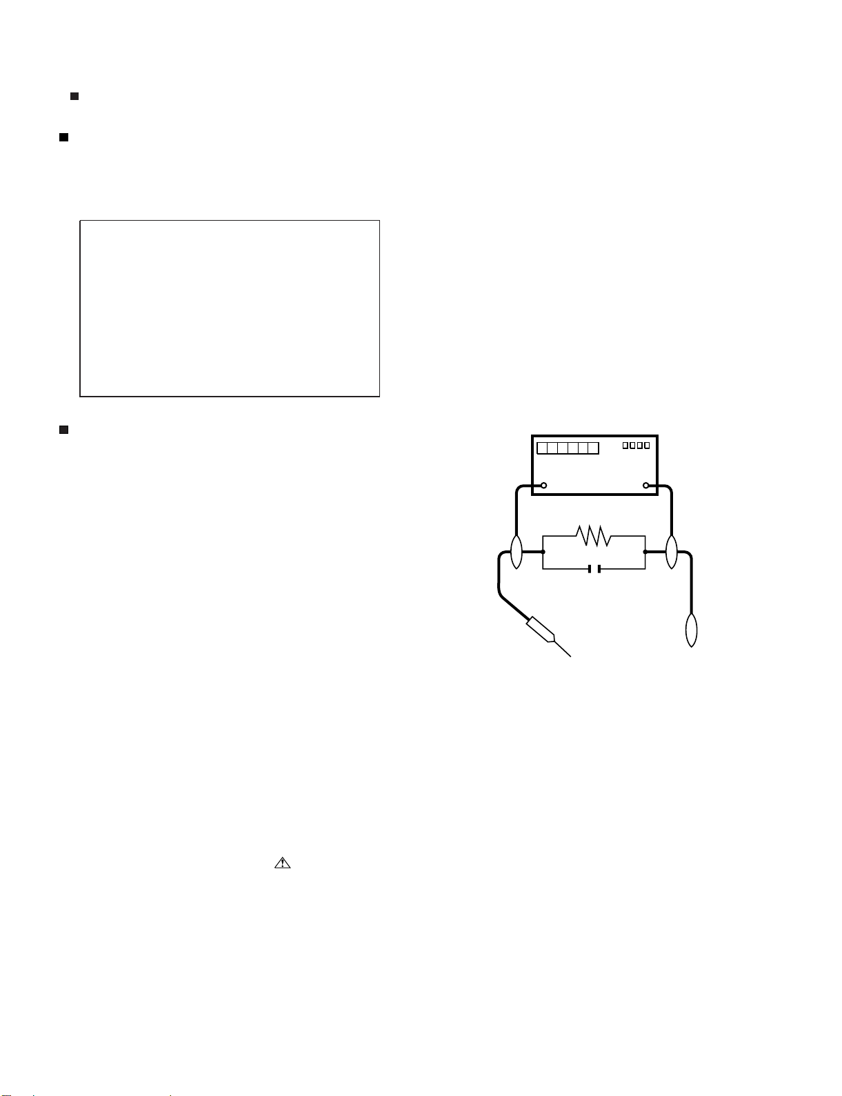
5. To be sure that no shock hazard exists, check for leakage current
in the following manner.
• Plug the AC cord directly into a 120 volt AC outlet.
• Using two clip leads, connect a 1.5k ohm, 10 watt resistor paralleled by a 0.15µF capacitor in series with all exposed metal cabinet
parts and a known earth ground, such as electrical conduit or electrical ground connected to an earth ground.
• Use an AC voltmeter having with 5000 ohm per volt, or higher, sensitivity or measure the AC voltage drop across the resistor.
• Connect the resistor connection to all exposed metal parts having a
return to the chassis (antenna, metal cabinet, screw heads, knobs
and control shafts, escutcheon, etc.) and measure the AC voltage
drop across the resistor.
All checks must be repeated with the AC cord plug connection
reversed. (If necessary, a nonpolarized adaptor plug must be used
only for the purpose of completing these checks.)
Any reading of 0.75 Vrms (this corresponds to 0.5 mA rms AC.) or
more is excessive and indicates a potential shock hazard which
must be corrected before returning the monitor to the owner.
DVM
AC SCALE
1.5k ohm
10W
0.15µF
TEST PROBE
TO EXPOSED
METAL PARTS
CONNECT TO
KNOWN EARTH
GROUND
///////////////////////////////////////////////////////////////////////////////////////////////////////////////////////////////////////////////////////////////////////////////////////////////////////////////////////////////////////////
SAFETY NOTICE
Many electrical and mechanical parts in LCD color television have
special safety-related characteristics.
These characteristics are often not evident from visual inspection, nor
can protection afforded by them be necessarily increased by using
replacement components rated for higher voltage, wattage, etc.
Replacement parts which have these special safety characteristics are
identified in this manual; electrical components having such features
are identified by " " and shaded areas in the Replacement Parts List
and Schematic Diagrams.
///////////////////////////////////////////////////////////////////////////////////////////////////////////////////////////////////////////////////////////////////////////////////////////////////////////////////////////////////////////
For continued protection, replacement parts must be identical to those
used in the original circuit.
The use of a substitute replacement parts which do not have the same
safety characteristics as the factory recommended replacement parts
shown in this service manual, may create shock, fire or other hazards.
i
Page 4
LC-52/60/70LE640U/C6400U,LC-80LE633U/844U (1st Edition)
PRECAUTIONS A PRENDRE LORS DE LA REPARATION
Ne peut effectuer la réparation qu' un technicien spécialisé qui s'est parfaitement accoutumé à toute vérification de sécurité et aux
conseils suivants.
A l'aide de deux fils à pinces, brancher une résistance de 1.5 kΩ
AVERTISSEMENT
1.
N'entreprendre aucune modification de tout circuit. C'est dangereux.
Débrancher le récepteur avant toute réparation.
2.
PRECAUTION: POUR LA PROTECTION CONTINUE CONTRE LES RISQUES D'INCENDIE,
REMPLACER LE FUSIBLE
F7001 (250V 5A) :
LC-52/60/70LE640U/C6400U
F7003 (250V 6.3A) :
LC-80LE844U,LC-60LE633U
•
10 watts en parallèle avec un condensateur de 0.15µF en série
avec toutes les pièces métalliques exposées du coffret et une terre
connue comme une conduite électrique ou une prise de terre
branchée à la terre.
Utiliser un voltmètre CA d'une sensibilité d'au moins 5000Ω/V pour
•
mesurer la chute de tension en travers de la résistance.
Toucher avec la sonde d'essai les pièces métalliques exposées qui
•
présentent une voie de retour au châssis (antenne, coffret métallique, tête des vis, arbres de commande et des boutons, écusson,
etc.) et mesurer la chute de tension CA en-travers de la résistance.
Toutes les vérifications doivent être refaites après avoir inversé la
fiche du cordon d'alimentation. (Si nécessaire, une prise
d'adpatation non polarisée peut être utilisée dans le but de terminer ces vérifications.)
La tension de pointe mesurèe ne doit pas dépasser 0.75V (correspondante au courant CA de pointe de 0.5mA).
Dans le cas contraire, il y a une possibilité de choc électrique qui
doit être supprimée avant de rendre le récepteur au client.
VERIFICATIONS CONTRE L'INCEN-DIE ET LE
CHOC ELECTRIQUE
Avant de rendre le récepteur à l'utilisateur, effectuer les vérifications suivantes.
Inspecter tous les faisceaux de câbles pour s'assurer que les fils
3.
ne soient pas pincés ou qu'un outil ne soit pas placé entre le châssis et les autres pièces métalliques du récepteur.
Inspecter tous les dispositifs de protection comme les boutons de
4.
commande non-métalliques, les isolants, le dos du coffret, les couvercles ou blindages de réglage et de compartiment, les réseaux
de résistancecapacité, les isolateurs mécaniques, etc.
S'assurer qu'il n'y ait pas de danger d'électrocution en vérifiant la
5.
fuite de courant, de la facon suivante:
Brancher le cordon d'alimentation directem-ent à une prise de cou-
•
rant de 120V. (Ne pas utiliser de transformateur d'isolation pour
cet essai).
/////////////////////////////////////////////////////////////////////////////////////////////////////////////////////////////////////////////////////////////////////////////////////////////////////////////////////////////////////////////
AUX PIECES
METALLIQUES
EXPOSEES
DVM
ECHELLE CA
1.5k ohm
10W
0.15
µ
SONDE D'ESSAI
F
BRANCHER A UNE
TERRE CONNUE
AVIS POUR LA SECURITE
De nombreuses pièces, électriques et mécaniques, dans les téléviseur ACL présentent des caractéristiques spéciales relatives à la sécurité, qui ne sont souvent pas évidentes à vue. Le degré de protection ne peut pas être nécessairement augmentée en utilisant des
pièces de remplacement étalonnées pour haute tension, puissance,
etc.
Les pièces de remplacement qui présentent ces caractéristiques sont
identifiées dans ce manuel; les pièces électriques qui présentent ces
particularités sont identifiées par la marque " " et hachurées dans la
liste des pièces de remplacement et les diagrammes schématiques.
/////////////////////////////////////////////////////////////////////////////////////////////////////////////////////////////////////////////////////////////////////////////////////////////////////////////////////////////////////////////
Pour assurer la protection, ces pièces doivent être identiques à celles
utilisées dans le circuit d'origine. L'utilisation de pièces qui n'ont pas
les mêmes caractéristiques que les pièces recommandées par l'usine,
indiquées dans ce manuel, peut provoquer des électrocutions, incendies, radiations X ou autres accidents.
ii
Page 5

LC-52/60/70LE640U/C6400U,LC-80LE633U/844U (1st Edition)
PRECAUTIONS FOR USING LEAD-FREE SOLDER
Employing lead-free solder
• “PWBs” of this model employs lead-free solder. The LF symbol indicates lead-free solder, and is attached on the PWBs and service manuals. The
alphabetical character following LF shows the type of lead-free solder.
Example:
Indicates lead-free solder of tin, silver and copper. Indicates lead-free solder of tin, silver and copper.
Using lead-free wire solder
• When fixing the PWB soldered with the lead-free solder, apply lead-free wire solder. Repairing with conventional lead wire solder may cause damage or accident due to cracks.
As the melting point of lead-free solder (Sn-Ag-Cu) is higher than the lead wire solder by 40 °C, we recommend you to use a dedicated soldering
bit, if you are not familiar with how to obtain lead-free wire solder or soldering bit, contact our service station or service branch in your area.
Soldering
• As the melting point of lead-free solder (Sn-Ag-Cu) is about 220 °C which is higher than the conventional lead solder by 40 °C, and as it has poor
solder wettability, you may be apt to keep the soldering bit in contact with the PWB for extended period of time. However, Since the land may be
peeled off or the maximum heat-resistance temperature of parts may be exceeded, remove the bit from the PWB as soon as you confirm the
steady soldering condition.
Lead-free solder contains more tin, and the end of the soldering bit may be easily corroded. Make sure to turn on and off the power of the bit as
required.
If a different type of solder stays on the tip of the soldering bit, it is alloyed with lead-free solder. Clean the bit after every use of it.
When the tip of the soldering bit is blackened during use, file it with steel wool or fine sandpaper.
• Be careful when replacing parts with polarity indication on the PWB silk.
Lead-free wire solder for servicing
PARTS CODE
ZHNDAi123250E BL J φ0.3mm 250g (1roll)
ZHNDAi126500E BK J φ0.6mm 500g (1roll)
ZHNDAi12801KE BM J φ1.0mm 1kg (1roll)
PRICE
RANK
PART
DELIVERY
DESCRIPTION
iii
Page 6

LC-52/60/70LE640U/C6400U,LC-80LE633U/844U (1st Edition)
LC52LE640U
OUTLINE
Service Manual
MAJOR SERVICE PARTS
PWB Unit
Ref No. Parts No. Description
N DKEYMF733FM82 MAIN Unit (LC-52/60/70LE640U,C6400U,LC-80LE633U)
N DKEYMF953FM01 MAIN Unit (LC-80LE844U)
N DUNTKF800FM53 KEY Unit
N DUNTKF975FM01 LCD CONTROL Unit (LC-52/60/70LE640U,C6400U)
N DUNTKF975FM07 LCD CONTROL Unit (LC-80LE633U)
N DUNTKF961FM07 LCD CONTROL Unit (LC-80LE844U)
N DUNTKG014FM01 ICON Unit (LC-52/60/70LE640U,C6400U)
N DUNTKF770FM02 ICON Unit (LC-80LE633U)
N DUNTKF770FM03 ICON Unit (LC-80LE844U)
N DUNTKG015FM01 R/C OPC Unit (LC-52/60/70LE640U,C6400U)
N DUNTKF494FM01 R/C OPC Unit (LC-80LE633U/844U)
N RUNTKA936WJQZ Wi-Fi Unit
N RUNTKA931WJQZ POWER/DRIVE Unit (LC-52LE640U/C6400U)
N RUNTKA932WJQZ POWER/DRIVE Unit (LC-60LE640U/C6400U)
N RUNTKA933WJQZ POWER/DRIVE Unit (LC-70LE640U/C6400U)
N RUNTKA903WJN1 POWER/LED DRIVE Unit (LC-80LE633U/844U)
N RUNTKA819WJQZ 3D-IR Unit (LC-80LE844U)
NOTE: • LC-52/60/70LE640U,C6400U
*1 Replace MAIN PWB Units (DKEYMF733FM**) in case of IC8401, IC3303 or IC8455 failure.
*2 Replace LCD CONTROL Units (DUNTKA975FM**) in case of IC5803 failure.
• LC-80LE633U
*1 Replace MAIN PWB Units (DKEYMF733FM**) in case of IC8401, IC3303, IC8455 or IC5803 failure.
• LC-80LE844U
*1 Replace MAIN PWB Units (DKEYMF953FM**) in case of IC3103 failure.
OTHER Unit
Ref No. Parts No. Description
N R1LK520D3GV00Z 52" LCD Panel Module Unit (LC-52LE640U/C6400U) (LK520D3GV00Z)
N R1LK600D3GV00Z 60" LCD Panel Module Unit (LC-60LE640U/C6400U) (LK600D3GV00Z)
N R1LK695D3GW80D 70" LCD Panel Module Unit (LC-70LE640U/C6400U) (LK695D3GW80D)
N R1LK800D3GW10Z 80" LCD Panel Module Unit (LC-80LE633U) (LK800D3GW10Z)
N R1LK800D3GW40Z 80" LCD Panel Module Unit (LC-80LE844U) (LK800D3GW40Z)
IC For Exclusive Use Of The Service
Ref No. Parts No. Description Q’ty
IC2001 RH-iXD241WJNSQ IC R5F21368CNFP (Monitor Microprocessor) (LC-52/60/70LE640U,C6400U,LC-80LE633U) 1
IC2001 RH-iXD241WJNUQ IC (Monitor Microprocessor) (LC-80LE844U) 1
Service Jigs
Ref No. Parts No. Description Q'ty
N QCNW-C222WJQZ Connecting Cord L=1000mm 80pins, LCD Control to LCD Panel, x2 2
N QCNW-M580WJQZ
N QCNW-L795WJQZ
N QCNW-L807WJQZ Connecting Cord L=1000mm 4pins, Main to LCD Control(PL) (LC-52/60/70LE640U,C6400U) 1
N QCNW-G405WJQZ Connecting Cord L=1000mm 4pins, Main to LCD Control(PL) (LC-80LE633U) 1
N QCNW-L214WJQZ Connecting Cord L=1000mm 64pins, LCD Control to LCD Panel (LC-80LE844U) 2
N QCNW-M580WJQZ Connecting Cord L=1000mm 41pins, Main to LCD Control (LV) (LC-80LE844U) 1
N QCNW-M539WJQZ Connecting Cord L=1000mm 24-24-4pins, Main to Power to LCD Control(PD) (LC-80LE844U) 1
Connecting Cord L=1000mm 41pins, Main to LCD Control (LW) (LC-52/60/70LE640U,C6400U,LC80LE633U)
Connecting Cord L=1000mm 24pins, Main to Power (PD) (LC-52/60/70LE640U,C6400U,LC80LE633U)
1
1
iv
Page 7

LC-52/60/70LE640U/C6400U,LC-80LE633U/844U (1st Edition)
LC52LE640U
CHAPTER 1. SPECIFICATIONS
Service Manual
[1] SPECIFICATIONS (LC-52/60/70LE640U/C6400U)
1 – 1
150
0.1
Page 8

LC-52/60/70LE640U/C6400U,LC-80LE633U/844U (1st Edition)
[2] SPECIFICATIONS (LC-80LE633U/844U)
1 – 2
Page 9

LC-52/60/70LE640U/C6400U,LC-80LE633U/844U (1st Edition)
1 – 3
Page 10

LC-52/60/70LE640U/C6400U,LC-80LE633U/844U (1st Edition)
tae
s
t
eaequpetcoe
cto
u
t
t
o
ope
ato
s
3
etasoteud
oSeectu
cto
LC52LE640U
CHAPTER 2. OPERATION MANUAL
Service Manual
[1] OPERATION MANUAL (LC-52/60/70LE640U/C6400U)
TV (Front)
OPC sensor *
TV (Rear/Side)
Center Icon illuminationRemote control sensor
* OPC: Optical Picture Control
POWER
button
MENU
button
INPUT
button
Channel
buttons
(
CH
Volume
buttons
(
VOL
USB 2
terminal
/)
/)
ETHERNET
terminal
Antenna/
Cable in
DIGITAL AUDIO
OUTPUT terminal
AUDIO IN terminal
(shared for PC IN
and HDMI 1) *3
*1*2
RS-232C terminal
PC IN terminal
VIDEO 2
terminals
VIDEO 1
terminals
COMPONENT
terminals
*1
AUDIO OUT terminal
*1
USB 1 terminal
HDMI 1 terminal
ARC: Audio Return Channel
HDMI 2 terminal
HDMI 3 terminal
HDMI 4 terminal
2 – 1
Page 11

Remote Control Unit
LC-52/60/70LE640U/C6400U,LC-80LE633U/844U (1st Edition)
1
18
19
2
3
4
5
20
21
6
7
8
9
10
11
22
23
24
25
26
12
13
27
14
15
28
29
16
30
17
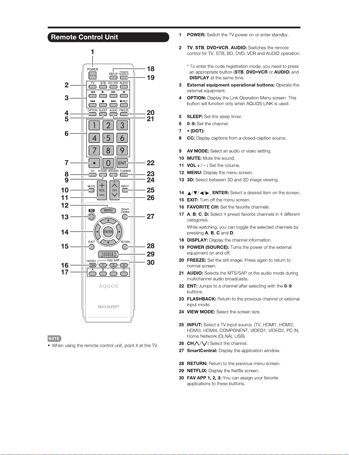
• When using the remote control unit, point it at the TV.
1 POWER: Switch the TV power on or enter standby.
2 TV, STB, DVD.VCR, AUDIO: Switches the remote
control for TV, STB, BD, DVD, VCR and AUDIO operation.
* To enter the code registration mode, you need to press
an appropriate button (STB, DVD
DISPLAY at the same time.
3 External equipment operational buttons: Operate the
external equipment.
4OPTION:Display the Link Operation Menu screen. This
button will function only when AQUOS LINK is used.
5 SLEEP: Set the sleep timer.
6 0-9: Set the channel.
٨
7
(DOT)
8CC:Display captions from a closed-caption source.
9AVMODE:Select an audio or video setting.
10 MUTE: Mute the sound.
11 VOL+/-: Set the volume.
12 MENU: Display the menu screen.
13 AAL: Display the TV+Web screen.
14 ˴/˴/˴/˴, ENTER: Select a desired item on the screen.
15 EXIT: Turn off the menu screen.
16 FAVORITE CH: Set the favorite channels.
17 A, B, C, D: Select 4 preset favorite channels in 4 different
categories.
While watching, you can toggle the selected channels by
pressing A, B, C and D.
18 DISPLAY: Display the channel information.
19 POWER (SOURCE): Turns the power of the external
equipment on and off.
20 FREEZE: Set the still image. Press again to return to
normal screen.
21 AUDIO: Selects the MTS/SAP or the audio mode during
multichannel audio broadcasts.
22 ENT: Jumps to a channel after selecting with the 0-9
buttons.
23 FLASHBACK: Return to the previous channel or external
input mode.
24 VIEW MODE: Select the screen size.
25 INPUT: Select a TV input source. (TV, HDMI1, HDMI2,
HDMI3, HDMI4, COMPONENT, VIDEO1, VIDEO2, PC IN,
Home Network (DLNA), USB)
26 CH˴/˴: Select the channel.
27 SmartCentral: Display the application window.
28 RETURN: Return to the previous menu screen.
29 NETFLIX: Display the Netfl ix screen.
30 FAV APP 1, 2, 3: You can assign your favorite
applications to these buttons.
٨
VCR or AUDIO) and
2 – 2
Page 12

LC-52/60/70LE640U/C6400U,LC-80LE633U/844U (1st Edition)
QUICK REFERENCE
Attaching the Stand
• Before attaching (or detaching) the stand, unplug the AC cord.
• Before performing work spread cushioning over the base area to lay the TV on. This will prevent it from being damaged.
CAUTION
• Attach the stand in the correct direction.
• Do not remove the stand from the TV unless using an optional wall mount bracket to mount it.
• Be sure to follow the instructions. Incorrect installation of the stand may result in the TV falling over.
• After attaching the stand to the TV, do not hold the stand when you put up, set up, move or lay down the TV.
Confirm that there are 12 screws (8 long screws
1
and 4 short screws) supplied with the stand unit.
Set the post for the stand unit onto the
Ԙ
2
polystyrene foam.
Attachthebasetothepost.
ԙ
Insert and tighten the 8 screws into the 8 holes
Ԛ
on the bottom of the base.
• Hold the stand unit securely with one hand, and then
tighten the screws.
Insert and tighten the 4 screws into the 4 holes on
4
the rear of the TV.
Short screws
2
2
1
1
1
FRONT
Insert the stand into the openings on the bottom of the TV.
3
• Make sure that the stand is firmly inserted into the TV.
Improper installation may result in tilting of the TV set.
Soft cushion
Long
screws
• To detach the stand, perform the steps in reverse order.
• In the installation procedure, be careful not to catch your
fingers between the TV set and the floor.
2 – 3
Page 13

LC-52/60/70LE640U/C6400U,LC-80LE633U/844U (1st Edition)
[2] OPERATION MANUAL (LC-80LE633U/844U)
• LC-80LE633U
2 – 4
Page 14

LC-52/60/70LE640U/C6400U,LC-80LE633U/844U (1st Edition)
• LC-80LE844U
2 – 5
Page 15
LC-52/60/70LE640U/C6400U,LC-80LE633U/844U (1st Edition)
2 – 6
Page 16

LC-52/60/70LE640U/C6400U,LC-80LE633U/844U (1st Edition)
2 – 7
Page 17

LC-52/60/70LE640U/C6400U,LC-80LE633U/844U (1st Edition)
LC52LE640U
CHAPTER 3. DIMENSIONS
[1] DIMENSIONS (LC-52LE640U/C6400U)
Service Manual
LC-52LE640U/LC-52C6400U
479/16(1208)
21
15
*1
7
/64(536)
3
/4(400)
815/32(215)
(771)
64
/
23
30
*1
Active area
*2
Thinnest part
(739)
32
/
3
29
(17)
64
/
43
4523/64(1152.0)
64
/
33
25
*1
(648.0)
(419)
2
/
1
16
17
(286)
64
/
11
(400)
4
/
3
15
41
5
(143)
/
64
131/8(333)
1
/
4
2
(114)
3
*2
1
/64(26.4)
27
2
/32(72)
AN-52AG4
6
(159)
Unit: inch (mm)
(51)
5°
64
/
1
2
(345)15
32
/
19
13
(391)
64
/
25
17
/
64
3 – 1
Page 18

LC-52/60/70LE640U/C6400U,LC-80LE633U/844U (1st Edition)
[2] DIMENSIONS (LC-60/70LE640U,C6400U)
LC-70LE640U/LC-70C6400U
6319/32(1615)
*1
217/64(536)
153/4(400)
(1009)
64
/
47
39
(976)
16
/
7
38
(115)
64
/
34
4
6019/32(1538.88)
815/32(215)
*1
(865.62)
32
/
3
34
(538)
16
/
3
21
(190)
64
/
31
7
(400)
4
/
3
15
23
5
(136)
/
64
5
(137)
21/64(51)
*2
Unit: inch (mm)
31/2(89)
1
/8(333)
13
5°
25
/
64
759/
(201)
(263)
64
/
23
10
(461)20
32
/
5
18
(512)
64
/
11
64
LC-60LE640U/LC-60C6400U
5417/32(1385)
*1
217/64(536)
153/4(400)
(872)
32
/
11
34
(839)
2
/
1
33
(52)
16
/
1
2
5211/32(1329.12)
16
/
7
29
815/32(215)
*1
(747.63)
(470)
2
/
1
18
(230)
16
/
1
9
(400)
4
/
3
15
3
5
(146)
/
4
417/
(115)
1
/8(333)
13
32
AN-52AG4
7
*2
1
/64(27.9)
59
2
/64(74)
6
(169)
(156)
5°
21
64
/
9
6
(395)17
16
/
9
15
(442)
32
/
13
/
32
*1
Active area
*2
Thinnest part
AN-52AG4
3 – 2
Page 19

[3] DIMENSIONS (LC-80LE633U/844U)
LC-52/60/70LE640U/C6400U,LC-80LE633U/844U (1st Edition)
3 – 3
Page 20

LC-52/60/70LE640U/C6400U,LC-80LE633U/844U (1st Edition)
LC52LE640U
CHAPTER 4. REMOVING OF MAJOR PARTS
Service Manual
[1] REMOVING OF MAJOR PARTS (LC-52LE640U/C6400U)
1. Removing of Stand Unit and Rear Cabinet.
1. Remove the 4 lock screws and detach the Stand Unit .
2. Remove the 1 lock screw and detach the AC Cord Cover .
3. Disconnect AC wire and detach the AC Cord .
4. Remove the 4 VESA Covers , 7 lock screws , 16 lock screws and detach the Rear Cabinet .
䎖
䎗
䎤䎦䎃䎦䏒䏕䏇䎃䎦䏒䏙䏈䏕
䎶䏗䏄䏑䏇䎃䎸䏑䏌䏗
䎹䎨䎶䎤䎃䎦䏒䏙䏈䏕
䎕
䎚
䎤䎦䎃䎦䏒䏕䏇
䎙
䎔
䎾䎤䎦䏀
䎾䎤䎦䏀
䎘
䎛
䎜
䎵䏈䏄䏕䎃䎦䏄䏅䏌䏑䏈䏗
4 – 1
Page 21

LC-52/60/70LE640U/C6400U,LC-80LE633U/844U (1st Edition)
[Precautions when fixing the Rear Cabinet]
When fixing the Rear Cabinet, be careful not to catch the backlight LED harness, speaker harness and other harnesses in it.
• The hooks on the external wall of the Rear Cabinet are fitted in the Front Cabinet Ass’y. After putting the Rear Cabinet in place, fit the hooks
securely; then tighten the screws.
(Work method of Rear Cabinet fixation)
Rear Cabinet
(Mat parts)
Front Cabinet Ass'y
(Luster parts)
There is a gap without the fingernail fitting in completely only when covering
with Rear Cabinet.
It becomes the factor of a gap increase of Front Cabinet Ass'y/Rear Cabinet
and the Rear Cabinet misregistration.
(Front Cabinet Ass’y/Rear Cabinet fingernail fixation place)
14 places
Please tighten the screw after Rear Cabinet is firmly pushed, and the
fingernail is confirmed.
4 – 2
Page 22

LC-52/60/70LE640U/C6400U,LC-80LE633U/844U (1st Edition)
2. Removing of Speaker (L/R), KEY Unit and Bottom Cover.
1. Remove the 2 lock screws .
2. Detach the Speaker (L) , Speaker (R) .
3. Disconnect the SP wire.
4. Disconnect the RC wire.
5. Detach the KEY Unit Ass’y .
6. Disconnect the KM wire.
7. Remove the 2 lock screws and detach the Key Button from Key Button Cover .
8. Detach the KEY Unit from Key Button .
9. Remove the 4 Hooks and detach the 2 Bottom Cover .
䎮䎨䎼䎃䎸䏑䏌䏗
䎮䏈䏜䎃䎥䏘䏗䏗䏒䏑䎃䎦䏒䏙䏈䏕
䎙
䎛
䎘
䎰䎤䎬䎱䎃䎸䏑䏌䏗
䎾䎶䎳䏀
䎾䎵䎦䏀
䎾䎮䎰䏀
䎮䎨䎼䎃䎸䏑䏌䏗䎃䎤䏖䏖䏃䏜
䎗
䎚
䎮䏈䏜䎃䎥䏘䏗䏗䏒䏑
䎔
䎫䏒䏒䏎
䎶䏓䏈䏄䏎䏈䏕䎃䎋䎵䎌
䎖
䎥䏒䏗䏗䏒䏐䎃䎦䏒䏙䏈䏕
䎫䏒䏒䏎
䎜
䎾䎶䎳䏀
䎶䏓䏈䏄䏎䏈䏕䎃䎋䎯䎌
䎕
䎔
4 – 3
Page 23

LC-52/60/70LE640U/C6400U,LC-80LE633U/844U (1st Edition)
3. Removing of Connectors
1. Disconnect the following connectors from the MAIN Unit. (PD, LV, PL, Cl, UB)
2. Disconnect the following connectors from the POWER/DRIVE Unit. (PD, LA)
3. Disconnect the following connectors from the LCD CONTROL Unit. (LV, PL)
䎳䎲䎺䎨䎵䎒䎧䎵䎬䎹䎨䎃䎸䏑䏌䏗
䎾䎯䎤䏀
䎾䎳䎧䏀
䎾䎳䎯䏀
䎯䎦䎧䎃䎦䎲䎱䎷䎵䎲䎯䎃䎸䏑䏌䏗
䎰䎤䎬䎱䎃䎸䏑䏌䏗
䎰䎤䎬䎱䎃䎸䏑䏌䏗
䎾䎯䎹䏀
䎾䎳䎧䏀
䎾䎯䎹䏀
䎾䎳䎯䏀
䎾䎦䎬䏀
䎾䎸䎥䏀
4 – 4
Page 24

LC-52/60/70LE640U/C6400U,LC-80LE633U/844U (1st Edition)
4. Removing of 52” LCD Panel Module Unit, LCD CONTROL Unit, MAIN Unit, POWER/DRIVE Unit.
1. Remove the 20 Hooks and detach the 52” LCD Panel Module Unit .
2. Remove the 2 Connecting Cords , 6 lock screws and detach the LCD CONTROL Unit .
3. Remove the 5 lock screws and detach the MAIN PWB Shield .
4. Remove the 3 lock screws and detach the MAIN Unit and Terminal Angle (Bottom) .
5. Remove the 6 lock screws and detach the POWER/DRIVE Unit .
6. Remove the 12 lock screws and detach the 2 Stand Fix Angle Ass’y .
7. Remove the 4 lock screws and detach the 4 VESA Angle Ass’y .
䎙
䎹䎨䎶䎤䎃䎤䏑䏊䏏䏈䎃䎤䏖䏖䏃䏜
䎹䎨䎶䎤䎃䎤䏑䏊䏏䏈䎃䎤䏖䏖䏃䏜
䎫䏒䏒䏎
䎶䏗䏄䏑䏇䎃䎩䏌䏛䎃䎤䏑䏊䏏䏈
䎤䏖䏖䎊䏜
䎔䎘
䎔䎙
䎔䎘
䎔䎙
䎫䏒䏒䏎
䎔䎗
䎔䎔
䎳䎲䎺䎨䎵䎒䎧䎵䎬䎹䎨
䎃䎸䏑䏌䏗
䎔䎕
䎯䎦䎧䎃䎦䎲䎱䎷䎵䎲䎯䎃䎸䏑䏌䏗
䎘
䎫䏒䏒䏎
䎰䎤䎬䎱䎃䎳䎺䎥䎃䎶䏋䏌䏈䏏䏇
䎹䎨䎶䎤䎃
䎤䏑䏊䏏䏈
䎔䎙
䎤䏖䏖䏃䏜
䎃䎃䎃䎃
䎔䎘
䎹䎨䎶䎤䎃
䎤䏑䏊䏏䏈
䎤䏖䏖䏃䏜
䎔䎙
䎔䎘
䎔
䎘䎕䎅䎯䎦䎧䎃䎳䏄䏑䏈䏏䎃䎰䏒䏇䏘䏏䏈䎃䎸䏑䏌䏗
䎔䎗
䎶䏗䏄䏑䏇䎃䎩䏌䏛䎃䎤䏑䏊䏏䏈䎃䎤䏖䏖䎊䏜
䎚
䎛
䎷䏈䏕䏐䏌䏑䏄䏏䎃䎤䏑䏊䏏䏈
䎔䎓
䎥䏒䏗䏗䏒䏐
䎫䏒䏒䏎
䎰䎤䎬䎱䎃䎸䏑䏌䏗
䎜
䎔䎖
䎔䎖
䎗
䎕
䎦䏒䏑䏑䏈䏗䏌䏑䏊䎃䎦䏒䏕䏇
4 – 5
Page 25

LC-52/60/70LE640U/C6400U,LC-80LE633U/844U (1st Edition)
5. Removing of Center Angle
1. Remove the 12 lock screws and detach the 2 Center Angles .
䎦䏈䏑䏗䏈䏕䎃䎤䏑䏊䏏䏈䎃
䎔
䎦䏈䏑䏗䏈䏕䎃䎤䏑䏊䏏䏈䎃
䎔
䎕䎕
䎘䎕䎅䎯䎦䎧䎃䎳䏄䏑䏈䏏䎃䎰䏒䏇䏘䏏䏈䎃䎸䏑䏌䏗
4 – 6
Page 26

LC-52/60/70LE640U/C6400U,LC-80LE633U/844U (1st Edition)
6. Removing of R/C OPC Unit, ICON Unit, Wi-Fi Unit.
1. Detach the R/C OPC Unit .
2. Disconnect the RA wire.
3. Detach the ICON Unit .
4. Disconnect the CI wire.
5. Detach the Wi-Fi Unit .
6. Disconnect the UB wire.
䎩䏕䏒䏑䏗䎃䎦䏄䏅䏌䏑䏈䏗䎃䎤䏖䏖䏃䏜
䎕
䎬䎦䎲䎱䎃䎸䏑䏌䏗
䎾䎦䎬䏀
䎖
䎺䏌䎐䎩䏌䎃䎸䏑䏌䏗
䎾䎸䎥䏀
䎾䎵䎤䏀
䎔
䎵䎒䎦䎃䎲䎳䎦䎃䎸䏑䏌䏗
4 – 7
Page 27

LC-52/60/70LE640U/C6400U,LC-80LE633U/844U (1st Edition)
[2] REMOVING OF MAJOR PARTS (LC-60LE640U/C6400U)
1. Removing of Stand Unit and Rear Cabinet.
1. Remove the 4 lock screws and detach the Stand Unit .
2. Remove the 1 lock screw and detach the AC Cord Cover .
3. Disconnect AC wire and detach the AC Cord .
4. Remove the 4 VESA Covers , 9 lock screws , 2 lock screws , 20 lock screws and detach the Rear Cabinet .
䎖
䎤䎦䎃䎦䏒䏕䏇䎃䎦䏒䏙䏈䏕
䎗
䎘
䎛
䎾䎤䎦䏀
䎶䏗䏄䏑䏇䎃䎸䏑䏌䏗
䎹䎨䎶䎤䎃䎦䏒䏙䏈䏕
䎕
䎤䎦䎃䎦䏒䏕䏇
䎙
䎔
䎜
䎚
䎛
[Precaution when removing the rear cabinet]
If the rear cabinet is removed with the set upright, the speakers may fall; it results in connector disconnection. Therefore, never remove the rear cabinet with the set upright.
Be sure to remove the rear cabinet with the screen side down.
䎾䎤䎦䏀
䎵䏈䏄䏕䎃䎦䏄䏅䏌䏑䏈䏗
䎔䎓
Screws for fixing Speaker
and Rear Cabinet
[Precaution when mounting the rear cabinet]
Put the speakers in place with the screen side down, and attach the rear cabinet.
Since the speakers are fixed by the rear cabinet, they cannot be fixed without the rear cabinet.
Speaker incline.
4 – 8
Speaker fall down.
Page 28

LC-52/60/70LE640U/C6400U,LC-80LE633U/844U (1st Edition)
[Precautions when fixing the Rear Cabinet]
When fixing the Rear Cabinet, be careful not to catch the backlight LED harness, speaker harness and other harnesses in it.
• The hooks on the external wall of the Rear Cabinet are fitted in the Front Cabinet Ass’y. After putting the Rear Cabinet in place, fit the hooks
securely; then tighten the screws.
(Work method of Rear Cabinet fixation)
Rear Cabinet
(Mat parts)
Front Cabinet Ass'y
(Luster parts)
There is a gap without the fingernail fitting in completely only when covering
with Rear Cabinet.
It becomes the factor of a gap increase of Front Cabinet Ass'y/Rear Cabinet
and the Rear Cabinet misregistration.
(Front Cabinet Ass’y/Rear Cabinet fingernail fixation place)
17 places
Please tighten the screw after Rear Cabinet is firmly pushed, and the
fingernail is confirmed.
4 – 9
Page 29

LC-52/60/70LE640U/C6400U,LC-80LE633U/844U (1st Edition)
2. Removing of Speaker (L/R), KEY Unit and Bottom Cover.
1. Detach the Speaker (L) , Speaker (R) .
2. Disconnect the SP wire.
3. Disconnect the RC wire.
4. Detach the KEY Unit Ass’y .
5. Disconnect the KM wire.
6. Remove the 2 lock screws and detach the Key Button from Key Button Cover .
7. Detach the KEY Unit from Key Button .
8. Remove the 4 Hooks and detach the 2 Bottom Cover .
䎰䎤䎬䎱䎃䎸䏑䏌䏗
䎮䏈䏜䎃䎥䏘䏗䏗䏒䏑䎃䎦䏒䏙䏈䏕
䎚
䎾䎮䎰䏀
䎮䎨䎼䎃䎸䏑䏌䏗䎃䎤䏖䏖䏃䏜
䎮䎨䎼䎃䎸䏑䏌䏗
䎙
䎖
䎗
䎘
䎮䏈䏜䎃䎥䏘䏗䏗䏒䏑
䎶䏓䏈䏄䏎䏈䏕䎃䎋䎵䎌
䎾䎶䎳䏀
䎾䎵䎦䏀
䎫䏒䏒䏎 䎫䏒䏒䏎
䎛
䎥䏒䏗䏗䏒䏐䎃䎦䏒䏙䏈䏕
䎕
䎾䎶䎳䏀
䎶䏓䏈䏄䏎䏈䏕䎃䎋䎯䎌
䎔
4 – 10
Page 30

LC-52/60/70LE640U/C6400U,LC-80LE633U/844U (1st Edition)
3. Removing of Connectors
1. Disconnect the following connectors from the MAIN Unit. (PD, LV, PL, Cl, UB)
2. Disconnect the following connectors from the POWER/DRIVE Unit. (PD, LA)
3. Disconnect the following connectors from the LCD CONTROL Unit. (LV, PL)
䎳䎲䎺䎨䎵䎒䎧䎵䎬䎹䎨䎃䎸䏑䏌䏗
䎾䎯䎤䏀
䎾䎳䎧䏀
䎾䎳䎯䏀
䎯䎦䎧䎃䎦䎲䎱䎷䎵䎲䎯䎃䎸䏑䏌䏗
䎰䎤䎬䎱䎃䎸䏑䏌䏗
䎰䎤䎬䎱䎃䎸䏑䏌䏗
䎾䎯䎹䏀
䎾䎳䎧䏀
䎾䎯䎹䏀
䎾䎳䎯䏀
䎾䎦䎬䏀
䎾䎸䎥䏀
4 – 11
Page 31

LC-52/60/70LE640U/C6400U,LC-80LE633U/844U (1st Edition)
4. Removing of 60” LCD Panel Module Unit, LCD CONTROL Unit, MAIN Unit, POWER/DRIVE Unit.
1. Remove the 21 Hooks and detach the 60” LCD Panel Module Unit .
2. Remove the 2 Connecting Cords , 6 lock screws and detach the LCD CONTROL Unit .
3. Remove the 5 lock screws and detach the MAIN PWB Shield .
4. Remove the 3 lock screws and detach the MAIN Unit and Terminal Angle (Bottom) .
5. Remove the 6 lock screws and detach the POWER/DRIVE Unit and AC Cord Barrier .
6. Remove the 12 lock screws and detach the 2 Stand Fix Angle Ass’y .
7. Remove the 16 lock screws and detach the 4 VESA Angle Ass’y .
䎙
䎹䎨䎶䎤䎃䎤䏑䏊䏏䏈䎃䎤䏖䏖䏃䏜
䎹䎨䎶䎤䎃䎤䏑䏊䏏䏈䎃䎤䏖䏖䏃䏜
䎔䎖
䎤䎦䎃䎦䏒䏇䏈䎃
䎥䏄䏕䏕䏌䏈䏕
䎫䏒䏒䏎
䎔䎚
䎔䎚
䎔䎙
䎳䎲䎺䎨䎵䎒䎧䎵䎬䎹䎨
䎃䎸䏑䏌䏗
䎔䎙
䎔䎕
䎔䎔
䎫䏒䏒䏎
䎰䎤䎬䎱䎃䎳䎺䎥䎃䎶䏋䏌䏈䏏䏇
䎔䎙
䎹䎨䎶䎤䎃
䎤䏑䏊䏏䏈䎃䎤䏖䏖䏃䏜
䎔䎚
䎔䎙
䎹䎨䎶䎤䎃
䎤䏑䏊䏏䏈
䎤䏖䏖䏃䏜
䎔䎚
䎚
䎫䏒䏒䏎
䎛
䎜
䎰䎤䎬䎱䎃䎸䏑䏌䏗
䎔䎓
䎷䏈䏕䏐䏌䏑䏄䏏䎃䎤䏑䏊䏏䏈
䎋䎥䏒䏗䏗䏒䏐䎌
䎫䏒䏒䏎
䎶䏗䏄䏑䏇䎃䎩䏌䏛䎃䎤䏑䏊䏏䏈
䎃䎤䏖䏖䎊䏜
䎔䎗
䎔䎘
䎔
䎙䎓䎅䎯䎦䎧䎃䎳䏄䏑䏈䏏䎃䎰䏒䏇䏘䏏䏈䎃䎸䏑䏌䏗
䎯䎦䎧䎃䎦䎲䎱䎷䎵䎲䎯
䎘
䎃䎸䏑䏌䏗
䎶䏗䏄䏑䏇䎃䎩䏌䏛䎃䎤䏑䏊䏏䏈䎃䎤䏖䏖䎊䏜
䎔䎘
䎔䎗
䎗
䎕
䎦䏒䏑䏑䏈䏗䏌䏑䏊䎃䎦䏒䏕䏇
4 – 12
Page 32

LC-52/60/70LE640U/C6400U,LC-80LE633U/844U (1st Edition)
5. Removing of R/C OPC Unit, ICON Unit, Wi-Fi Unit.
1. Detach the R/C OPC Unit .
2. Disconnect the RA wire.
3. Detach the ICON Unit .
4. Disconnect the CI wire.
5. Detach the Wi-Fi Unit .
6. Disconnect the UB wire.
䎩䏕䏒䏑䏗䎃䎦䏄䏅䏌䏑䏈䏗䎃䎤䏖䏖䏃䏜
䎬䎦䎲䎱䎃䎸䏑䏌䏗
䎾䎦䎬䏀
䎺䏌䎐䎩䏌䎃䎸䏑䏌䏗
䎾䎸䎥䏀
䎾䎵䎤䏀
䎖䎕
䎵䎒䎦䎃䎲䎳䎦䎃䎸䏑䏌䏗
䎔
4 – 13
Page 33

LC-52/60/70LE640U/C6400U,LC-80LE633U/844U (1st Edition)
[3] REMOVING OF MAJOR PARTS (LC-70LE640U/C6400U)
1. Removing of Stand Unit and Rear Cabinet Ass’y.
1. Remove the 4 lock screws and detach the Stand Unit .
2. Remove the 1 lock screw and detach the AC Cord Cover .
3. Disconnect AC wire and detach the AC Cord .
4. Remove the 4 VESA Covers , 9 lock screws and 21 lock screws and detach the Rear Cabinet Ass’y .
䎖
䎤䎦䎃䎦䏒䏕䏇䎃䎦䏒䏙䏈䏕
䎗
䎤䎦䎃䎦䏒䏕䏇
䎔
䎘
䎾䎤䎦䏀
䎶䏗䏄䏑䏇䎃䎸䏑䏌䏗
䎹䎨䎶䎤䎃䎦䏒䏙䏈䏕
䎕
䎙
䎛
䎚
䎾䎤䎦䏀
䎜
䎵䏈䏄䏕䎃䎦䏄䏅䏌䏑䏈䏗䎃䎤䏖䏖䏃䏜
[Precautions when mounting and removing the rear cabinet]
Basically, there is no problem as in LC-60LE632U. However, the screws on both sides are not tightened together with the Rear Cabinet Ass’y.
The inside is fixed by the module and Speaker.
Therefore, it does not come away completely, but only one side can come off.
Tighten together with the
Rear Cabinet Ass'y.
Fix with the 70" LCD Panel Module Unit.
4 – 14
Only one side (outer) can come off.
Page 34

LC-52/60/70LE640U/C6400U,LC-80LE633U/844U (1st Edition)
Push
Push
Push
Push
Push
Push
Push
Push
CAUTION
Set it so that there may not be a clearance between Front Cabinet Ass'y and Rear Cabinet Ass'y.
19
places
[Precautions for assembly]
There is a gap without the fingernail fitting
in completely only when covering with Rear Cabinet Ass'y.
(Front Cabinet Ass’y/Rear Cabinet Ass’y fingernail fixation place)
The fingernail is surely fixed when Rear cabinet Ass'y is
firmly pushed, and the gap disappears.
4 – 15
Page 35

LC-52/60/70LE640U/C6400U,LC-80LE633U/844U (1st Edition)
2. Removing of Speaker (L/R) and KEY Unit.
1. Disconnect the SP wire.
2. Remove the 2 lock screws and detach the Speaker (L) , Speaker (R) .
3. Disconnect the RC wire.
4. Detach the KEY Unit Ass’y .
5. Disconnect the KM wire.
6. Remove the 2 lock screws and detach the Key Button from Key Button Cover .
7. Detach the KEY Unit from Key Button .
8. Remove the 4 Hooks and detach the 2 Bottom Cover .
䎰䎤䎬䎱䎃䎸䏑䏌䏗
䎮䏈䏜䎃䎥䏘䏗䏗䏒䏑䎃䎦䏒䏙䏈䏕
䎛
䎮䎨䎼䎃䎸䏑䏌䏗䎃䎤䏖䏖䏃䏜
䎮䎨䎼䎃䎸䏑䏌䏗
䎚
䎾䎮䎰䏀
䎗
䎘
䎮䏈䏜䎃䎥䏘䏗䏗䏒䏑
䎙
䎶䏓䏈䏄䏎䏈䏕䎃䎋䎵䎌
䎾䎶䎳䏀
䎾䎵䎦䏀
䎫䏒䏒䏎 䎫䏒䏒䏎
䎜
䎜
䎾䎶䎳䏀
䎥䏒䏗䏗䏒䏐䎃䎦䏒䏙䏈䏕
䎖
䎔
䎔
䎶䏓䏈䏄䏎䏈䏕䎃䎋䎯䎌
䎕
4 – 16
Page 36

LC-52/60/70LE640U/C6400U,LC-80LE633U/844U (1st Edition)
3. Removing of Connectors
1. Disconnect the following connectors from the MAIN Unit. (PD, LV, PL, Cl, UB)
2. Disconnect the following connectors from the POWER/DRIVE Unit. (PD, LA)
3. Disconnect the following connectors from the LCD CONTROL Unit. (LV, PL)
䎳䎲䎺䎨䎵䎒䎧䎵䎬䎹䎨䎃䎸䏑䏌䏗
䎾䎯䎤䏀
䎾䎳䎧䏀
䎾䎳䎯䏀
䎯䎦䎧䎃䎦䎲䎱䎷䎵䎲䎯䎃䎸䏑䏌䏗
䎰䎤䎬䎱䎃䎸䏑䏌䏗
䎰䎤䎬䎱䎃䎸䏑䏌䏗
䎾䎯䎹䏀
䎾䎯䎹䏀
䎾䎳䎯䏀
䎾䎦䎬䏀
䎾䎸䎥䏀
䎾䎳䎧䏀
4 – 17
Page 37

LC-52/60/70LE640U/C6400U,LC-80LE633U/844U (1st Edition)
4. Removing of 70” LCD Panel Module Unit, LCD CONTROL Unit, MAIN Unit, POWER/DRIVE Unit.
1. Remove the 24 Hooks and detach the 70” LCD Panel Module Unit .
2. Remove the 2 Connecting Cords , 6 lock screws and detach the LCD CONTROL Unit .
3. Remove the 2 look screws and detach the 2 Spacers .
4. Remove the 6 lock screws and detach the POWER/DRIVE Unit .
5. Remove the 5 lock screws and detach the MAIN PWB Shield .
6. Remove the 3 lock screws and detach the MAIN Unit and Terminal Angle (Bottom) .
7. Remove the 12 lock screws and detach the 2 Stand Fix Angle Ass’y .
8. Remove the 16 lock screws and detach the 4 VESA Angle Ass’y .
䎔䎓
䎹䎨䎶䎤䎃䎤䏑䏊䏏䏈䎃䎤䏖䏖䏃䏜
䎹䎨䎶䎤䎃䎤䏑䏊䏏䏈䎃䎤䏖䏖䏃䏜
䎫䏒䏒䏎
䎔䎛
䎔䎛
䎔䎚
䎳䎲䎺䎨䎵䎒䎧䎵䎬䎹䎨
䎃䎸䏑䏌䏗
䎔䎚
䎰䎤䎬䎱䎃䎳䎺䎥䎃䎶䏋䏌䏈䏏䏇
䎔䎔
䎛
䎔䎚
䎹䎨䎶䎤䎃䎤䏑䏊䏏䏈
䎜
䎃䎤䏖䏖䏃䏜
䎔䎕
䎔䎛
䎹䎨䎶䎤䎃
䎤䏑䏊䏏䏈
䎔䎚
䎔䎖
䎰䎤䎬䎱䎃䎸䏑䏌䏗
䎤䏖䏖䏃䏜
䎔䎛
䎔䎗
䎫䏒䏒䏎
䎷䏈䏕䏐䏌䏑䏄䏏䎃䎤䏑䏊䏏䏈
䎋䎥䏒䏗䏗䏒䏐䎌
䎫䏒䏒䏎
䎔
䎫䏒䏒䏎
䎶䏓䏄䏆䏈䏕
䎶䏗䏄䏑䏇䎃䎩䏌䏛䎃䎤䏑䏊䏏䏈
䎃䎤䏖䏖䎊䏜
䎚䎓䎅䎯䎦䎧䎃䎳䏄䏑䏈䏏䎃䎰䏒䏇䏘䏏䏈䎃䎸䏑䏌䏗
䎯䎦䎧䎃䎦䎲䎱䎷䎵䎲䎯䎃䎸䏑䏌䏗
䎚
䎘
䎙
䎚
䎶䏓䏄䏆䏈䏕
䎙
䎶䏗䏄䏑䏇䎃䎩䏌䏛䎃䎤䏑䏊䏏䏈䎃䎤䏖䏖䎊䏜
䎔䎙
䎔䎙
䎗
䎔䎘
䎕
䎦䏒䏑䏑䏈䏗䏌䏑䏊䎃䎦䏒䏕䏇
䎔䎘
4 – 18
Page 38

LC-52/60/70LE640U/C6400U,LC-80LE633U/844U (1st Edition)
5. Removing of R/C OPC Unit, ICON Unit, Wi-Fi Unit.
1. Detach the R/C OPC Unit .
2. Disconnect the RA wire.
3. Detach the ICON Unit .
4. Disconnect the CI wire.
5. Detach the Wi-Fi Unit .
6. Disconnect the UB wire.
䎩䏕䏒䏑䏗䎃䎦䏄䏅䏌䏑䏈䏗䎃䎤䏖䏖䏃䏜
䎾䎦䎬䏀
䎬䎦䎲䎱䎃䎸䏑䏌䏗
䎾䎸䎥䏀
䎺䏌䎐䎩䏌䎃䎸䏑䏌䏗
䎾䎵䎤䏀
䎔䎖䎕
䎵䎒䎦䎃䎲䎳䎦䎃䎸䏑䏌䏗
4 – 19
Page 39

LC-52/60/70LE640U/C6400U,LC-80LE633U/844U (1st Edition)
[4] REMOVING OF MAJOR PARTS (LC-80LE633U/844U)
1. Removing of Stand Unit and Rear Cabinet Ass’y.
1. Remove the 4 lock screws and detach the Stand Unit .
2. Remove the 10 lock screws and 26 lock screws and detach the Rear Cabinet .
4
2Stand Unit
3
4
[Precautions when mounting and removing the rear cabinet]
Therefore, it does not come away completely, but only one side can come off.
1
4
Rear Cabinet
8
Tighten together with the
Rear Cabinet Ass'y.
Fix with the 80" LCD Panel Module Unit.
4 – 20
Only one side (outer) can come off.
Page 40

LC-52/60/70LE640U/C6400U,LC-80LE633U/844U (1st Edition)
[How to remove Rear Cabinet Ass’y]
* Please do following works by 2 persons
Do following works as → → →
1) Please grasp the swelling of a speaker and pull back with pushing down.
Remove one hook under an operation.
2) Put a hand in terminal area and pulls back, and the other hand holds top side of TV set.
Remove all-right hand side hook.
2WVCJCPFDGVYGGPVGTOKPCNCPINGCPF4GCT
%CDKPGV#UU[CPFRWNNUVJGODCEM
4 – 21
Page 41

LC-52/60/70LE640U/C6400U,LC-80LE633U/844U (1st Edition)
3) Hold left side of TV set by one hand, and put the other hand between bottom cover and Rear Cabinet Ass’y.
And pull Rear Cabinet Ass’y.
Remove all-left hand side hook.
4) Two persons stand on the both sides of TV SET, and have a Front Cabinet Ass’y and a Rear Cabinet Ass’y by each hand.
Two persons pull a Rear Cabinet Ass’y horizontally back, simultaneously and remove it.
4 – 22
Page 42

LC-52/60/70LE640U/C6400U,LC-80LE633U/844U (1st Edition)
Push
Push
Push
Push
Push
Push
Push
Push
CAUTION
Set it so that there may not be a clearance between Front Cabinet Ass'y and Rear Cabinet Ass'y.
[Precautions for assembly]
There is a gap without the fingernail fitting
in completely only when covering with Rear Cabinet Ass'y.
(Front Cabinet Ass’y/Rear Cabinet Ass’y fingernail fixation place)
The fingernail is surely fixed when Rear cabinet Ass'y is
firmly pushed, and the gap disappears.
4 – 23
Page 43

LC-52/60/70LE640U/C6400U,LC-80LE633U/844U (1st Edition)
2. Removing of Speaker (L/R) and KEY Unit.
1. Disconnect the SP wire.
2. Remove the 2 lock screws and detach the Speaker (L) , Speaker (R) .
3. Disconnect the RC wire.
4. Detach the KEY Unit Ass’y .
5. Disconnect the KM wire.
6. Remove the 2 lock screws and detach the Key Button from Key Button Cover .
7. Detach the KEY Unit from Key Button .
MAIN Unit
4
KEY Unit Ass'y
[SP]
5
7
KEY Unit
[RC]
8
[SP]
31Speaker (R) 2
Speaker (L)
[KM]
6 Key Button
1
[How to remove KEY Unit Ass’y]
1) When you remove KEY Unit Ass’y, please be sure to remove harness from WH, and to hold the bottom of KEY Unit Ass’y.
Key Button
Cover
4 – 24
Page 44

LC-52/60/70LE640U/C6400U,LC-80LE633U/844U (1st Edition)
3. Removing of Connectors, 80” LCD Panel Module Unit Ass’y.
1. Disconnect the following connectors from the MAIN Unit. (LV, PD, Cl, UB)
2. Disconnect the following connectors from the POWER/LED DRIVE Unit. (L1, L2, PD)
3. Disconnect the following connectors from the LCD Control Unit. (PL, LW)
4. Remove the 27 Hooks and detach the 80” LCD Panel Module Unit Ass’y .
5. Detach the 2 Bottom cover .
Hock
Hock
[L1] [L2]
POWER/LED DRIVE
Unit
[PD]
Hock
[PL]
LCD
Control
Unit
2Bottom cover
MAIN Unit
[PD]
Hock
1 80" LCD Panel
Module
Unit Ass'y
[LW]
MAIN Unit
[LV]
[CI]
[UB]
4 – 25
Page 45

LC-52/60/70LE640U/C6400U,LC-80LE633U/844U (1st Edition)
4. Removing of LCD CONTROL Unit, MAIN Unit, POWER/LED DRIVE Unit.
1. Remove the 2 Connecting Cords , 6 lock screws and detach the LCD CONTROL Unit .
2. Remove the 5 lock screws and detach the Shield (MAIN Unit) .
3. Remove the 3 lock screws and detach the MAIN Unit and Terminal Angle (Bottom) .
4. Remove the 6 lock screws and detach the POWER/LED DRIVE Unit .
5. Remove the 12 lock screws and detach the 2 Stand Angles .
6. Remove the 16 lock screws and detach the 4 VESA Angle Ass’ys .
Stand Angle
POWER/
LED DRIVE
Unit
Ass'y
Ass'y
11
14
15VESA Angle
14
15VESA Angle
4
13
12
3
10
LCD
Control
Unit
12
1 FFC
14
15 VESA Angle Ass'y
14
15 VESA Angle Ass'y
13
Stand
Angle
5
80" LCD Panel
Module Unit
MAIN Unit
8
7
9
Terminal
Angle
(Bottom)
6
Shield
(MAIN Unit)
4 – 26
Page 46

LC-52/60/70LE640U/C6400U,LC-80LE633U/844U (1st Edition)
5. Removing of R/C OPC Unit, ICON Unit, Wi-Fi Unit.
1. Detach the R/C OPC Unit .
2. Disconnect the RC wire.
3. Detach the ICON Unit .
4. Disconnect the CI wire.
5. Detach the Wi-Fi Unit .
6. Disconnect the UB wire.
7. Detach the WiFi Attachment .
Front Cabinet Ass'y
4 WiFi Attachment
[CI]
[UB]
[RA]
3ICON Unit 2 Wi-Fi Unit 1 R/C OPE Unit
4 – 27
Page 47

LC-52/60/70LE640U/C6400U,LC-80LE633U/844U (1st Edition)
PSPA Z C8 54 WJ K Z
TCON CPU COOLER
[5] The location putting on the heat measure sheet (LC-52/60/70LE640U/C6400U)
1. MAIN PWB Unit
• LC-52/60LE640U/C6400U
Put 䇼PSPAZC805WJKZ䇽 along these
ruled lines.
• LC-70LE640U/6400U
2. LCD Control Unit (LC-60LE640U/C6400U)
PSPAZC741WJKZ
835
4 – 28
Page 48

LC-52/60/70LE640U/C6400U,LC-80LE633U/844U (1st Edition)
[6] The location putting on the heat measure sheet (LC-80LE844U)
1. MAIN PWB Unit
PSPAZC835WJKZ
PSPAZC741WJKZ
4 – 29
Page 49

LC-52/60/70LE640U/C6400U,LC-80LE633U/844U (1st Edition)
[7] Precautions for assembly (LC-52/60/70LE640U/C6400U)
1. Points to be checked and precautions when servicing the unit
Mount the main PWB Ass’y on the backlight chassis and check that the EMI-prevention parts are not peeled and twisted from the access holes. (The
EMI-prevention parts, conductive nonwoven fabric gaskets, must be seen from the access holes.)
[Countermeasure]
Attach the conductive nonwoven fabric gaskets on the shielded case on the main PWB.
• LC-52/60LE640U,C6400U
PSPA Z C6 90 WJ Z Z
PSPA Z C6 91 WJ Z Z x 2
4 – 30
PSPA Z C6 91 WJ Z Z
Page 50

LC-52/60/70LE640U/C6400U,LC-80LE633U/844U (1st Edition)
(4) Stick *****
PSPA Z C7 40 WJ Z Z
(CONDUCTR: 9 x 14 6 )
PMLT-A691WJQZ
• LC-70LE640U/C6400U
PMLT-A691WJQZ
PMLT-A690WJQZ
PMLT-A690WJQZ
4 – 31
Page 51

LC-52/60/70LE640U/C6400U,LC-80LE633U/844U (1st Edition)
State where the main PWB and shielded case are assembled
Access hole
Access hole
The following is a drawing mounting the main PWB Ass’y on the backlight chassis. (The parts indicated by -> are the access holes for confirmation.)
(Main PWB Ass’y => State where the shielded case and RF terminal angle are mounted on the main PWB)
4 – 32
Page 52

LC-52/60/70LE640U/C6400U,LC-80LE633U/844U (1st Edition)
[8] Precautions for assembly (LC-80LE633U/844U)
1. Points to be checked and precautions when servicing the unit
Mount the main PWB Ass’y on the backlight chassis and check that the EMI-prevention parts are not peeled and twisted from the access holes. (The
EMI-prevention parts, conductive nonwoven fabric gaskets, must be seen from the access holes.)
[Countermeasure]
Attach the conductive nonwoven fabric gaskets on the shielded case on the main PWB.
PMLT-A679WJQZ
PMLT-A678WJQZx2pcs
Attach the conductive nonwoven fabric gasket on the RF terminal angle.
(PMLT-A680WJQZ)
State where the main PWB and shielded case are assembled
PSPAZC740WJZZ
Access hole
Access hole
4 – 33
Page 53

LC-52/60/70LE640U/C6400U,LC-80LE633U/844U (1st Edition)
The following is a drawing mounting the main PWB Ass’y on the backlight chassis. (The parts indicated by -> are the access holes for confirmation.)
(Main PWB Ass’y => State where the shielded case and RF terminal angle are mounted on the main PWB)
4 – 34
Page 54

LC-52/60/70LE640U/C6400U,LC-80LE633U/844U (1st Edition)
LC52LE640U
CHAPTER 5. ADJUSTMENT
Service Manual
[1] ADJUSTMENT PROCEDURE (LC-52/60/70LE640U/C6400U)
The adjustment values are set to the optimum conditions at the factory before shipping. If a value should become improper or an adjustment is
required due to part replacement, make an adjustment according to the following procedure.
1. After replacement of any PWB unit and/or IC for repair, please note the following.
• When replacing the following units, make sure to prepare the new units loaded with updated software.
MAIN Unit: DKEYMF733FM82 (LC-52/60/70LE640U/C6400U)
• When replacing the LCD control PWB, perform the VCOM adjustment.
2. Upgrading of each microprocessor software
CAUTION: Never “POWER OFF” the unit when software upgrade is ongoing.
Otherwise the system may be damaged beyond recovery.
2.1. Software version upgrade
The model employs the following software.
• Main software (please use a software version after BSMK_LE640_xxx.USB).
• Monitor microprocessor software (please use a software version after BM2SMxxx.SMB.)
The main software, monitor microprocessor software can be upgraded by using a general-purpose USB Memory.
The followings are the procedures for upgrading, explained separately for the main software, monitor microprocessor software.
2.2. Main software version upgrade
2.2.1 Get ready before you start
• USB Memory of 128MB or higher capacity.
• PC running on Windows 98/98SE/ME/2000/XP operating system.
• USB Memory reader/writer or PC with a USB port.
• The file system of a USB memory is FAT. (FAT32 supports)
• Use the USB memory without other functions. (lock and memory reader...etc)
2.2.2 Preparations
To upgrade the main software, it is necessary to get ready the USB Memory for version upgrade before you start.
Follow the steps below and create the USB Memory for version upgrade.
1. Copy the file BSMK_LE640_xxx.USB for version upgrade to the root directory (folder) of the USB Memory.
NOTE: In the USB Memory drive, do not store other folders or unrelated files, or more than one file for version upgrade.
Now the USB Memory for version upgrade is ready.
5 – 1
Page 55

LC-52/60/70LE640U/C6400U,LC-80LE633U/844U (1st Edition)
2.2.3 How to upgrade the software
1. Unplug the AC cord.
2. Insert the USB Memory for version upgrade into the service socket.
3. Plug in the AC cord with power button pressed down.
4. After 5 seconds, unpress the power button.
5. After the unit startup, the system upgrade screen as shown below within 20-40 seconds.
Software Update
MAIN Version
SUB MICOM Version
PANEL EEPROM
MAIN
SUB MICOM
PANEL EEPROM
26%
SAME VERSION
NO DATA
090U1112051
㧙㧙㧙㧙㧙
㧙㧙㧙㧙
52LE640U
6. Even a single failure in the process will trigger the upgrade failure screen.
Software Update
MAIN Version
SUB MICOM Version
PANEL EEPROM
UPGRADE FAILURE
MAIN
SUB MICOM
PANEL EEPROM
Project ID
NO DATA
NO DATA
㧙㧙㧙㧙㧙
㧙㧙㧙㧙㧙
㧙㧙㧙㧙
52LE640U
NOTE: In the event of a failure, repeat the upgrade process. If the process repeatedly fails, it is likely that the hardware need fixing.
7. Upon completion of the whole process, the upgrade success screen as shown below appears. You can check the new software version on this
screen. The version information appears after the upgrade is complete.
Software Update
MAIN Version
SUB MICOM Version
PANEL EEPROM
UPGRADE SUCCESS
MAIN
SUB MICOM
PANEL EEPROM
100%
SAME VERSION
NO DATA
090U1112051
㧙㧙㧙㧙㧙
㧙㧙㧙㧙
52LE640U
8. Unplug the AC cord and remove the USB Memory for version upgrade.
9. Now the software version upgrade is complete.
NOTE: When you are done with the software version upgrade, start the set, go to the top page of the adjustment process screen and check the main
software version information.
5 – 2
Page 56

LC-52/60/70LE640U/C6400U,LC-80LE633U/844U (1st Edition)
2.3. Monitor microprocessor software version upgrade
Create the USB memory for monitor microprocessor software version upgrade in the same manner as explained in the “Main software version
upgrade”.
Copy the file BSMK_LE640_xxx.USB and BM2SMxxx.SMB. (named temporarily) for monitor microprocessor software version upgrade to the USB
memory.
2.3.1 How to upgrade the software
1. Unplug the AC cord.
2. Insert the USB Memory for version upgrade into the service socket.
3. Plug in the AC cord with power button pressed down.
4. After 5 seconds, unpress the power button.
CAUTION: • The moment this operation is done, the upgrading of the monitor microprocessor software starts. While the upgrade is ongoing, never
5. After the unit startup, the upgrade starts. The power led will blink continuously. Also, an upgrade screen will be shown during a minor upgrade.
power off the unit. Otherwise the upgrade will fail and the system may be serious damaged beyond recovery (inability to start).
• After the monitor microprocessor software is upgraded, also perform the ‘Industry Init’.
Software Update
MAIN Version
SUB MICOM Version
PANEL EEPROM
MAIN
SUB MICOM
PANEL EEPROM
NO DATA
50%
NO DATA
㧙㧙㧙㧙㧙
0.820
㧙㧙㧙㧙
52LE640U
6. If the upgrade fails, power led will stop blinking. Also, the upgrade failure screen will be shown if upgrade screen was shown at 5.
Software Update
MAIN Version
SUB MICOM Version
PANEL EEPROM
UPGRADE FAILURE
MAIN
SUB MICOM
PANEL EEPROM
NO DATA
SAME VERSION
NO DATA
㧙㧙㧙㧙㧙
㧙㧙㧙㧙㧙
㧙㧙㧙㧙
52LE640U
NOTE: In the event of a transient failure, upgrade will be automatically retried up to three times. If the process repeatedly fails, hardware may be the
cause.
7. The upgrade success screen will be shown if upgrade screen was shown at 5.
Software Update
MAIN Version
SUB MICOM Version
PANEL EEPROM
UPGRADE SUCCESS
MAIN
SUB MICOM
PANEL EEPROM
NO DATA
100%
NO DATA
㧙㧙㧙㧙㧙
0.820
㧙㧙㧙㧙
52LE640U
8. Unplug the AC cord and remove the USB Memory for version upgrade.
9. Now the software version upgrade is complete.
NOTE: When you are done with the software version upgrade, start the set, go to the top page of the adjustment process screen and check the mon-
itor microprocessor software version information and panel size information.
5 – 3
Page 57

LC-52/60/70LE640U/C6400U,LC-80LE633U/844U (1st Edition)
3. Entering and exiting the adjustment process mode
1) Before entering the adjustment process mode, the AV position RESET in the video adjustment menu.
2) While holding down the “VOL (–)” and “INPUT” keys at a time, plug in the AC cord of the main unit to turn on the power.
The letter “<K>” appears on the screen.
3) Next, hold down the “VOL (–)” and “CH ( )” keys at a time.
(The “VOL (–)” and “CH ( )” keys should be pressed and held until the display appears.)
Multiple lines of blue characters appearing on the display indicate that the unit is now in the adjustment process mode.
When you fail to enter the adjustment process mode (the display is the same as normal startup), retry the procedure.
4) To exit the adjustment process mode after the adjustment is done, unplug the AC cord from the outlet to make a forced shutdown. (When the
power was turned off with the remote controller, once unplug the AC cord and plug it again. In this case, wait 10 seconds or so before plugging.)
CAUTION: Use due care in handling the information described here lest your users should know how to enter the adjustment process mode. If the
settings are tampered in this mode, unrecoverable system damage may result.
4. Remote controller key operation and description of display in adjustment process mode
1) Key operation
Remote controller key Main unit key Function
CH ( / )
CH ( / )
VOL (+/–) VOL (+/–) Changing a selected item setting (+1/ –1)
Cursor (UP/DOWN) ————— Turing a page (PREVIOUS/NEXT)
Cursor (LEFT/RIGHT) ————— Changing a selected line setting (+10/ –10)
INPUT ————— Input switching (toggle switching)
ENTER ————— Executing a function
*Input mode is switched automatically when relevant adjustment is started so far as the necessary input signal is available.
2) Description of display
Moving an item (line) by one (UP/DOWN)
(1) Current page/
Total pages
1/28 TUNER AUTO USA 60_UNDER
MAIN Version
BOOT Version
Monitor / Monitor BOOTVersion
T-CON Version / LED CON Version
NETFLIX ESN
WIDEVINE DEVICE ID
FRC Version
TOUCH SENSOR/IR Micom Version
TEMPERATURE 6E
LAMP ERROR
MONITOR ERR CAUSE
NORMAL STANDBY CAUSE
ERROR STANDBY CAUSE
(2) Current selected input
(3) Current color system
0.90 (U 2011/12/05 1 A)
BSMKxxx
0.90 / 0.90
201112052d523c41/478936600000
ERR-1
ERR-1
201112052d523c41
0000/---
0
1) 11 B00000040:30 2) 11 B00000040:11
3) 11 B00000039:11 4) 11 B00000025:52
1 RC_STNBY
00000
(4) Destination
(5) LCD Panel size/Speaker type
(6) Adjustment
process menu
header
(7) Parameters
5 – 4
Page 58

LC-52/60/70LE640U/C6400U,LC-80LE633U/844U (1st Edition)
5. List of adjustment process mode menu
The character string in brackets [ ] will appear as a page title in the adjustment process menu header.
Page Line Item Description Remarks (adjustment detail, etc.)
1 1 MAIN Version Main software version
2BOOT Version
3 Monitor / Monitor BOOT Version Monitor and monitor boot software version
4 T-CON Version / LED CON Version LCD controller software version
5 NETFLIX ESN
6 WIDEVINE DEVICE ID
7 FRC Version
8 TOUCH SENSOR/IR Micom Version
9 TEMPERATURE Panel temperature
10 LAMP ERROR Number of termination due to lamp error
11 MONITOR ERR CAUSE
12 NORMAL STANDBY CAUSE Refer to *1 under the list for details
13 ERROR STANDBY CAUSE Refer to *2 under the list for details
2 1 INDUSTRY INIT Initialization to factory settings
2 INDUSTRY INIT(-Public)
3 PUBLIC MODE Public mode
4 Center Acutime Accumulated main operation time
5 RESET Reset
6 Backlight Acutime Accumulated monitor operation time
7 RESET Reset
8 LAMP ERROR RESET Reset LAMP ERROR
9 VIC XPOS X-coordinate setting for VIC READ
10 VIC YPOS Y-coordinate setting for VIC READ
11 VIC COLOR Collected color data setting for VIC READ
12 VIC SIGNAL TYPE Signal type setting for VIC READ
13 VIC READ Picture level acquisition function Level appears in green on the upper right
3 1 N358 ALL ADJ(INPUT2) CVBS and TUNER signal level adjustment
2 N358 MAIN ADJ(INPUT2) CVBS signal level adjustment
3 TUNER DAC ADJ TUNER signal level adjustment
4 N358 CONTRAST A_GAIN
5 N358 CONTRAST D_GAIN
6 N358 CONTRAST OFFSET
7 TUNER CONTRAST A_GAIN
8 TUNER CONTRAST D_GAIN
9 TUNER CONTRAST OFFSET
4 1 TUNER VCHIP TEST(69ch) Tuning test and VCHIP test (69ch)
2 TUNER VCHIP TEST(7ch) Tuning test and VCHIP test (7ch)
3 TUNER VCHIP TEST(10ch) Tuning test and VCHIP test (10ch)
4 TUNER VCHIP TEST(15ch) Tuning test and VCHIP test (15ch)
5 INSPECT USB TERM
6 HDMI EDID WRITE
7 HDMI CEC TEST
5 1 COMP15K ADJ(INPUT1) Component 15K picture level adjustment (main)
2 COMP15K Y A_GAIN
3 COMP15K Cb A_GAIN
4 COMP15K Cr A_GAIN
5 COMP15K Y OFFSET
6 COMP15K Cb OFFSET
7 COMP15K Cr OFFSET
8 COMP15K A_CLAMP
6 1 COMP33K ADJ(INPUT1) Component 33K picture level adjustment (main)
2 COMP33K Y A_GAIN
3 COMP33K Cb A_GAIN
4 COMP33K Cr A_GAIN
5 COMP33K Y OFFSET
6 COMP33K Cb OFFSET
7 COMP33K Cr OFFSET
8 COMP33K A_CLAMP
5 – 5
Page 59

LC-52/60/70LE640U/C6400U,LC-80LE633U/844U (1st Edition)
Page Line Item Description Remarks (adjustment detail, etc.)
7 1 ANALOG RGB ADJ Analog RGB picture level adjustment
2 R A_GAIN
3 G A_GAIN
4 B A_GAIN
5 R OFFSET
6 G OFFSET
7 B OFFSET
8 RGB_A_CLAMP
8 1 VCOM ADJ VCOM adjustment value
9 1 LEV1 Standard value 1 Adjustment gradation setting.
2 LEV2 Standard value 2
3 LEV3 Standard value 3
4 LEV4 Standard value 4
5 LEV5 Standard value 5
6 LEV6 Standard value 6
10 1 MG1R WB adjustment Point 1, R adjustment value Parameter for six-point adjustment
2 MG1G WB adjustment Point 1, G adjustment value
3 MG1B WB adjustment Point 1, B adjustment value
4 MG2R WB adjustment Point 2, R adjustment value
5 MG2G WB adjustment Point 2, G adjustment value
6 MG2B WB adjustment Point 2, B adjustment value
7 MG3R WB adjustment Point 3, R adjustment value
8 MG3G WB adjustment Point 3, G adjustment value
9 MG3B WB adjustment Point 3, B adjustment value
11 1 MG4R WB adjustment Point 4, R adjustment value Parameter for six-point adjustment
2 MG4G WB adjustment Point 4, G adjustment value
3 MG4B WB adjustment Point 4, B adjustment value
4 MG5R WB adjustment Point 5, R adjustment value
5 MG5G WB adjustment Point 5, G adjustment value
6 MG5B WB adjustment Point 5, B adjustment value
7 MG6R WB adjustment Point 6, R adjustment value
8 MG6G WB adjustment Point 6, G adjustment value
9 MG6B WB adjustment Point 6, B adjustment value
12 1 LO R 1
2LO G 1
3LO B 1
4LO Y 1
5LO R 2
6LO G 2
7LO B 2
8LO Y 2
9LO R 3
10 LO G 3
11 LO B 3
12 LO Y 3
13 1 LO R 4
2LO G 4
3LO B 4
4LO Y 4
5LO R 5
6LO G 5
7LO B 5
8LO Y 5
9LO R 6
10 LO G 6
11 LO B 6
12 LO Y 6
13 CTEMP SELECT
5 – 6
Page 60

LC-52/60/70LE640U/C6400U,LC-80LE633U/844U (1st Edition)
Page Line Item Description Remarks (adjustment detail, etc.)
14 1 MODE SELECT
2 POS SELECT
3POS MIN
4POS MID1
5POS MID2
6POS MID3
7POS MID4
8POS MID5
9POS MID6
10 POS MAX
15 1 CD MIN
2 CD MID1
3 CD MID2
4 CD MID3
5 CD MID4
6 CD MID5
7 CD MID6
8 CD MAX
16 1 CALC
2 RESET
3VAL1
4VAL2
5VAL3
6VAL4
7VAL5
8VAL6
9 GAMMA ADJ TEMP
17 1 MONITOR TIME OUT
2 MONITOR MAX TEMP
3 MONITOR ERROR CAUSE RESET
18 1 LCD TEST PATTERN
2 LCD TEST PATTERN1
3 LCD TEST PATTERN2
4 LCD TEST PATTERN3
5 LCD TEST PATTERN4
6 TV TEST PATTERN 1
7 TV TEST PATTERN 2
19 1 T-CON VERSION EXT.1 PRIMROSE 2D Version
2 T-CON VERSION EXT.2 PRIMROSE 3D Version
3 T-CON VERSION EXT.3 Blank (Not Use)
4 T-CON VERSION EXT.4 Blank (Not Use)
20 1 READ/WRITE
2 SLAVE ADDRESS
3 RESISTER ADDRESS UPPER
4 RESISTER ADDRESS LOWER
5 WRITE DATA UPPER
6WRITE DATA LOWER
7 READ DATA UPPER
8 READ DATA LOWER
21 1 POWER LED BRIGHTNESS
2 MENU LED BRIGHTNESS
3 INPUT LED BRIGHTNESS
4 CH UP LED BRIGHTNESS
5 CH DOWN LED BRIGHTNESS
6 VOL UP LED BRIGHTNESS
7 VOL DOWN LED BRIGHTNESS
8 LOGO LED BRIGHTNESS
9 ICON LED BRIGHTNESS
10 ICON LED BRIGHTNESS
(STANDBY)
11 3D LED BRIGHTNESS
5 – 7
Page 61

LC-52/60/70LE640U/C6400U,LC-80LE633U/844U (1st Edition)
Page Line Item Description Remarks (adjustment detail, etc.)
22 1 POWER KEY SENSITIVITY
2 MENU KEY SENSITIVITY
3 INPUT KEY SENSITIVITY
4 CH UP KEY SENSITIVITY
5 CH DOWN KEY SENSITIVITY
6 VOL UP KEY SENSITIVITY
7 VOL DOWN KEY SENSITIVITY
23 1 KEY STRENGTH GET MODE
2 POWER KEY STRENGTH
3 MENU KEY STRENGTH
4 INPUT KEY STRENGTH
5 CH UP KEY STRENGTH
6 CH DOWN KEY STRENGTH
7 VOL UP KEY STRENGTH
8 VOL DOWN KEY STRENGTH
24 1 CROSSTALK ADJ MODE
2 CROSSTALK TH1
3 CROSSTALK TH2
4 CROSSTALK TH3
5 CROSSTALK TH4
6 CROSSTALK GAIN1
7 CROSSTALK GAIN2
8 CROSSTALK GAIN3
25 1 WIFI SSID 2.4GHz Set AP SSID
2 WIFI SSID 5GHz Set AP SSID
3 WIFI RSSI 2.4GHz Set RSSI threshold
4 WIFI RSSI 5GHz Set RSSI threshold
5 WIFI TIME 2.4GHz Set Time Out
6 WIFI TIME 5GHz Set Time Out
7 WIFI RSSI TEST Execute test
8 WIFI RSSI RESULT Display test result
26 1 KEY LOCK (1217)
2 KOUTEI AREA ALL CLEAR
3 A MODE AREA CLEAR
4 BACKUP AREA CLEAR
5 B MODE AREA CLEAR
6EXECUTION
27 1 ERROR STANDBY CAUSE1
2 ERROR STANDBY CAUSE2
3 ERROR STANDBY CAUSE3
4 ERROR STANDBY CAUSE4
5 ERROR STANDBY CAUSE5
6 ERROR STANDBY CAUSE RESET
28 1 EEP SAVE Writing setting values to EEPROM
2 EEP RECOVER Reading setting values from EEPROM
3MODEL NAME
4 PANEL SIZE
5 SETTING FOR ADJ
6 VERUP FLAG ENABLE
7 SHARP RC ENABLE
8 PANEL LIMIT
9 PANEL RANGE LIMIT
10 SHORT CHECK MODE
11 SHORT CHECK CURRENT
12 CURRENT SW
13 TEST NETWORK UPDATE
5 – 8
Page 62

LC-52/60/70LE640U/C6400U,LC-80LE633U/844U (1st Edition)
*1 Details of P1.12 (NORMAL STANDBY CAUSE)
When TV set is powered off due to normal use or product specification, the last cause will be recorded.
The code, character string and description for the standby cause are below.
If you power off by remote, the cause will not be recorded.
Code Character string Description
2 NO_OPERT No operation off
3 NO_SIGNA No signal off
6 SLEEP_TM Off timer
8 OFF_232C Command from RS232C
*2 Details of P1.13 (ERROR STANDBY CAUSE)
When TV set is powered off due to any anomaly detection, the past 5 causes will be recorded.
You can confirm the time those causes occurred and character string in the adjustment process mode menu. (Page 27/28)
The time is accumulated total after TV set is powered on, and the value corresponds to “Center Acutime” in the adjustment process mode menu.
The code, character string and description for the standby cause are below.
If no error has occurred, the code is 0 and the character string is “NO RECORD”.
Code Character string Description
1A E_MONITR Monitor trouble detected
1C E_CVICBT Driver boot error
22 E_TCNERR Software abnormality of LCD controller
48 E_MRESET Failure of resetting menu settings (Initial Setup - Reset)
50 E_TCNF_S T-CON FPGA status error
54 E_TCON_E T-CON hung-up
Monitor ERR STBY table
Outline: Communication/Power failure detected by the monitor microprocessor is stored in EEPROM, and last 4 abnormal
can be confirmed in the Process mode A.
Location: Page 1 of the process mode A: MONITOR ERR CAUSE. “0” if there is no error. It is cleared to 0 on the last page of
the process mode A.
Display Error description
02 Initial communication from the main CPU is not received. Check UART bus between main CPU and sub CPU.
03 Only the initial communication is received.
04 Until panel information request reception
05 Until initialization completion reception
06 Until version notification transmission
07 Until start-up information notification transmission
08 Until start-up information response reception
09 Until time-out setting reception
0A Request time-out
0B Restart time-out during the beginning of time acquisition start-up
0C Ending sequence time-out
0D Preset start-up time-out during completion
0E Download, start-up time-out
0F Time acquisition time-out
11 Regular communication time-out
16 Backlight error See p.6-5
1A Monitor temperature failure - Check TV setting environment
- Check the other monitor (ref No.)
1E DET_13V failure Check 13V power line.
1F DET_D3V3 failure Check D3V3 power line.
21 DET_PNLxxV failure Check T-CON power line
23 Error standby request from the main CPU Check ERROR STANDBY CAUSE (p.5-8)
5 – 9
Page 63

LC-52/60/70LE640U/C6400U,LC-80LE633U/844U (1st Edition)
1/2 1/2
1/2
1/2
6. Special features
* STANDBY CAUSE (Page 1/28)
Display of a cause (code) of the last standby
The cause of the last standby is recorded in EEPROM whenever possible.
Checking this code will be useful in finding a problem when you repair the troubled set.
* EEP SAVE (Page 28/28)
Storage of EEP adjustment value
* EEP RECOVER (Page 28/28)
Retrieval of EEP adjustment value from storage area
7. Writing the microprocessor software
7.1. Writing the main microprocessor software and monitor microprocessor software
(Main PWB: QPWBXF733WJN2)
Adjustment item Adjustment conditions Adjustment procedure
1 Writing the main micropro-
cessor software and monitor microprocessor software
<Main PWB>
Checker process
Checking the file version
Checking the USB memory
1) Using the checker, connect the specified writing tool to the SC8452 (TL8461 TL8475).
2) Using the checker, connect the USB memory to the J9502 (TL9503, TL9506 -
9508).
3) Apply the specified voltage to the PWB and boot it up with the tool connected.
4) Send the software writing start command via RS232C.
5) Send the writing status check command and confirm the response of OK. Then
turn off the power.
CAUTION: When the USB memory is not inserted or reading error occurs, nothing
is written.
8. Signal adjustment
8.1. LCD section adjustment [LCD module adjustment]
Adjustment item Adjustment conditions Adjustment procedure
1 Opposite bias adjustment
(LCD module adjustment
item)
Adjustment in the center
position of the panel
1) Enter the process mode using the process adjustment remote control.
2) Select [VCOM ADJ] using the Channel / keys on the remote control.
3) Press the Enter key to check that the pattern for adjustment is displayed.
4) Make adjustment so that the flicker located in the center of the screen is mini-
5) If the optimum condition is obtained in step 4, press the Enter key to turn off the
CAUTION: * Make adjustment with no ANT signal (since the brightness is changed
[Adjustment position]
mized using the Volume +/- keys on the remote control.
pattern.
by the active backlight).
5 – 10
Page 64

LC-52/60/70LE640U/C6400U,LC-80LE633U/844U (1st Edition)
8.2. Image adjustment
8.2.1 Device check
Before adjustment, check that the adjustment jig and signal source are set for Sharp LCD US.
Signal generator level adjustment check (Adjust to the standard value level.)
• Composite signal: 0.714Vp-p ± 0.02Vp-p (Pedestal to white)
• 15K component signal: Y level: 0.714Vp-p± 0.02Vp-p (Pedestal to white)
PB/PR level: 0.7Vp-p ± 0.02Vp-p
• 33K component signal: Y level: 0.7Vp-p ± 0.02Vp-p (Pedestal to white)
PB/PR level: 0.7Vp-p ± 0.02Vp-p
• Analog RGB: RGB level: 0.7Vp-p ± 0.02Vp-p (Pedestal to white)
8.2.2 Process mode
Adjustment point Adjustment conditions Adjustment procedure
Process mode Enter the process adjustment mode using the process adjustment remote control.
8.2.3 Composite N358 signal/tuner adjustment
Adjustment point Adjustment conditions Adjustment procedure
1 Setting N358 signal
US-10ch
• Send the N358 color bar (color saturation: 75%) signal to the composite input.
• Send the in-house signal (use US-10ch) to TUNER.
[Video input signal] [In-house US-10ch]
Color saturation: 75%
0% black
2 Automatic adjustment exe-
cution
100% white 100% white
Point the cursor to [ N358 ALL ADJ(INPUT2)] and press the [Enter] key.
The adjustment is complete when [ N358 ALL ADJ(INPUT2) OK] is displayed.
8.2.4 Component 15K signal adjustment
Adjustment point Adjustment conditions Adjustment procedure
1 Setting 480i signal • Send the 100% color bar signal to the component input.
2 Automatic adjustment exe-
cution
Color saturation: 100%
100% white 0% black
Point the cursor to [ COMP15K ADJ(INPUT1)] and press the [Enter] key.
The adjustment is complete when [ COMP15K ADJ(INPUT1) OK] is displayed.
480i
100% color bar
5 – 11
Page 65

LC-52/60/70LE640U/C6400U,LC-80LE633U/844U (1st Edition)
8.2.5 Component 33K signal adjustment
Adjustment point Adjustment conditions Adjustment procedure
1 Setting 1080i signal • Send the 100% color bar signal to the component input.
2 Automatic adjustment exe-
cution
8.2.6 Analog RGB signal adjustment
Adjustment point Adjustment conditions Adjustment procedure
1 Setting Signal: XGA
(1024x768) 60Hz
SYNC: HV separate
2 Automatic adjustment exe-
cution
8.2.7 Tuner/V-CHIP adjustment
Adjustment point Adjustment conditions Adjustment procedure
1 Setting NTSC RF signal
US-7(AIR)ch
2 Automatic adjustment exe-
cution
Color saturation: 100%
100% white 0% black
Point the cursor to [ COMP33K ADJ(INPUT1)] and press the [Enter] key.
The adjustment is complete when [ COMP33K ADJ(INPUT1) OK] is displayed.
• Send the 100% color bar signal to the PC input.
100% white 0% black
Point the cursor to [ ANALOG RGB ADJ] and press the [Enter] key.
The adjustment is complete when [ ANALOG RGB ADJ OK] is displayed.
• Send the NTSC signal to the RF antenna input.
Point the cursor to [ VCHIP TEST(*07ch)] and press the [Enter] key.
(* Adjust the selected channel to the in-house signal.)
The adjustment is OK when [ VM-OK] is displayed in green.
(NG when VM-NG is displayed in red.)
1080i
100% color bar
XGA (1024x768)
100% color bar
5 – 12
Page 66

LC-52/60/70LE640U/C6400U,LC-80LE633U/844U (1st Edition)
9. White balance adjustment
9.1. White balance adjustment (For details about the adjustment procedure, refer to “Kameyama Model Integrated Monitor
WB Adjustment Specification V1.92”.)
Adjustment
point
1 Setting 1) Set the unit to the following conditions.
2 Automatic
adjustment execution
Adjustment conditions Adjustment procedure
AV MODE: [DYNAMIC]
Backlight: +16
Active Backlight: OFF
Aging Time: Min. 60 minutes
2) Connect the unit with the white balance adjustment jig.
[Command]
Process mode
KRSW0001
KKT10037
Setting
KY0F0000
0SDS0001
SBSL0016
Multi-point adjustment mode
MSET0001
Point 6
LEV60232
MG6G****
MG6B****
MG6R****
Point 5
LEV50202
MG5G****
MG5B****
MG5R****
Point 4
LEV40174
MG4G****
MG4B****
MG4R****
Point 3
LEV30120 Level Reference value Adjustment spec Inspection spec
MG3G****
MG3B**** y=0.277
MG3R****
Point 2
LEV20059 y=0.277
MG2G****
MG2B**** y=0.277
MG2R****
Point 1
LEV10046 y=0.277
MG1G****
MG1B****
MG1R****
Writing
MSET0003
[Adjustment procedure]
1) Send the “adjustment process” code using the remote control.
2) Set the point 6 to the specified gradation, specify the strongest color as the fixed
color, and adjust the RGB so that it becomes the standard value through negative
adjustment.
3) Set the point 5 to the specified gradation, set the G correction value (808 x G value of
point 6/928) (fractions rounded off) and adjust the RB so that it becomes the standard
value.
4) Set the point 4 to the specified gradation, set the G correction value (696 x G value of
point 6/928) (fractions rounded off) and adjust the RB so that it becomes the standard
value.
5) Set the point 3 to the specified gradation, set the G correction value (480 x G value of
point 6/928) (fractions rounded off) and adjust the RB so that it becomes the standard
value.
6) Set the point 2 to the specified gradation, set the G correction value (236 x G value of
point 6/928) (fractions rounded off) and adjust the RB so that it becomes the standard
value.
7) Set the point 1 to the specified gradation, set the G correction value (184 x G value of
point 6/928) (fractions rounded off) and adjust the RB so that it becomes the standard
value.
8) Write the adjustment value by the MSET0003 command and turn off the AC power.
* RGB initial value of point 6: Set gradation 928
* RGB initial value of points 1 to 5: G correction value of each point
(At each point, make adjustment so that the remainder of the RGB adjustment value/
4 is equal.)
[Adjustment value]
* According to the “Standard settings” submitted by the Technical Department
[LC60LE632U] teaching set
[Adjustment standard value]
Measuring instrument: [Minolta CA-210] Technical measuring instrument
Point 6 928
Point 5 808
Point 4 696
Point 3 480
Point 2 236
Point 1 184
Remarks Setting conditions for inspection
X=0.272
X=0.272
y=0.277
X=0.272
X=0.272
X=0.272
0.277
y=
X=0.272
AV MODE: [DYNAMIC] (Reset)
Monochro: ON
Active Backlight: OFF
Aging Time: Min. 60 minutes
±0.0010 ±0.0020
±0.0010 ±0.0020
±0.0015 ±0.0030
±0.0020 ±0.0040
±0.0030 ±0.0060
±0.004 ±0.0080
5 – 13
Page 67

LC-52/60/70LE640U/C6400U,LC-80LE633U/844U (1st Edition)
10. Key writing
10.1. EDID writing (Main PWB: QPWBXF733WJN2)
1. Write the MAC key data on IC8455 mounted on the main PWB.
2. Carry out thorough data management to avoid redundant writing of data.
If the IC where data is written is damaged, replace the PWB since only the IC cannot be changed.
10.2. MAC key writing (MAIN PWB: QPWBXF733WJN2)
1. Write the NETFLIX/WMDRM key data on IC8401 mounted on the main PWB.
2. Carry out thorough data management to avoid redundant writing of data.
If the IC where data is written is damaged, replace the PWB since only the IC cannot be changed.
10.3. NETFLIX/WMDRM key writing (MAIN PWB: QPWBXF733WJN2)
1. Write the wide vine key data on IC8401 mounted on the main PWB.
2. Carry out thorough data management to avoid redundant writing of data.
If the IC where data is written is damaged, replace the PWB since only the IC cannot be changed.
NOTE: For EDID of the analog RGB (DSUB 15pin), write the data on the process menu just like HDMI.
11. Factory setting
After completing the factory setting, pull out the AC cord to complete the setting.
CAUTION: Do not turn on the power after completing the factory setting. If the power is turned on, configure the factory setting again.
Adjustment point Adjustment conditions Adjustment procedure
1 Factory setting Complete the setting by
pulling out the AC cord.
• Point the cursor to [INDUSTRY INIT (+Cause)], set to “ON” using [+]/[-] of the [VOL]
key, and press the [ENT] key.
The version confirmation screen appears on the green screen. It is completed when
[SUCCESS] is displayed at the top.
(If error occurs, [ERROR] is displayed on the red screen.)
• Turn off the AC power.
The following items are initialized when configuring the factory setting.
1) User set value
2) Channel data (broadcasting frequency, etc.)
3) Password setting value
4) Operating time
5) Standby Cause
6) Auto installation flag
7) V-CHIP block setting value
12. Software version
1. Main microprocessor
BSMK_LE640_xxx.USB
BSMK_LE640_xxx.DAT
2. Monitor microprocessor
BM2SMxxx.SMB
13. Writing the inch and model name onto EEPROM
LE640U/C6400U
1. Enter the adjustment process mode.
2. Point the cursor to [MODEL NAME] (Page 28/28).
3. Select "LE640U" or "C6400U", and press [Enter] key.
4. "OK" is displayed.
5. Point the cursor to [PANEL SIZE] (Page 28/28).
6. Select "52" or "60" or "70", and press [Enter] key.
7. Moments later image is displayed.
8. Turn off power
9. Turn on power
5 – 14
Page 68

LC-52/60/70LE640U/C6400U,LC-80LE633U/844U (1st Edition)
[2] ADJUSTMENT PROCEDURE (LC-80LE633U)
The adjustment values are set to the optimum conditions at the factory before shipping. If a value should become improper or an adjustment is
required due to part replacement, make an adjustment according to the following procedure.
1. After replacement of any PWB unit and/or IC for repair, please note the following.
• When replacing the following units, make sure to prepare the new units loaded with updated software.
MAIN Unit: DKEYMF733FM82 (LC-80L633U)
• When replacing the LCD control PWB, perform the VCOM adjustment.
2. Upgrading of each microprocessor software
CAUTION: Never “POWER OFF” the unit when software upgrade is ongoing.
Otherwise the system may be damaged beyond recovery.
2.1. Software version upgrade
The model employs the following software.
• Main software (please use a software version after BSMK_LE640_xxx.USB).
• Monitor microprocessor software (please use a software version after BM2SMxxx.SMB.)
The main software, monitor microprocessor software can be upgraded by using a general-purpose USB Memory.
The followings are the procedures for upgrading, explained separately for the main software, monitor microprocessor software.
2.2. Main software version upgrade
2.2.1 Get ready before you start
• USB Memory of 128MB or higher capacity.
• PC running on Windows 98/98SE/ME/2000/XP operating system.
• USB Memory reader/writer or PC with a USB port.
• The file system of a USB memory is FAT. (FAT32 supports)
• Use the USB memory without other functions. (lock and memory reader...etc)
2.2.2 Preparations
To upgrade the main software, it is necessary to get ready the USB Memory for version upgrade before you start.
Follow the steps below and create the USB Memory for version upgrade.
1. Copy the file BSMK_LE640_xxx.USB for version upgrade to the root directory (folder) of the USB Memory.
NOTE: In the USB Memory drive, do not store other folders or unrelated files, or more than one file for version upgrade.
Now the USB Memory for version upgrade is ready.
5 – 15
Page 69

LC-52/60/70LE640U/C6400U,LC-80LE633U/844U (1st Edition)
2.2.3 How to upgrade the software
1. Unplug the AC cord.
2. Insert the USB Memory for version upgrade into the service socket.
3. Plug in the AC cord with power button pressed down.
4. After 5 seconds, unpress the power button.
5. After the unit startup, the system upgrade screen as shown below within 20-40 seconds.
Software Update
MAIN Version
SUB MICOM Version
PANEL EEPROM
MAIN
SUB MICOM
PANEL EEPROM
26%
SAME VERSION
NO DATA
090U1112051
㧙㧙㧙㧙㧙
㧙㧙㧙㧙
80LE633U
6. Even a single failure in the process will trigger the upgrade failure screen.
Software Update
MAIN Version
SUB MICOM Version
PANEL EEPROM
UPGRADE FAILURE
MAIN
SUB MICOM
PANEL EEPROM
Project ID
NO DATA
NO DATA
㧙㧙㧙㧙㧙
㧙㧙㧙㧙㧙
㧙㧙㧙㧙
80LE633U
NOTE: In the event of a failure, repeat the upgrade process. If the process repeatedly fails, it is likely that the hardware need fixing.
7. Upon completion of the whole process, the upgrade success screen as shown below appears. You can check the new software version on this
screen. The version information appears after the upgrade is complete.
Software Update
MAIN Version
SUB MICOM Version
PANEL EEPROM
UPGRADE SUCCESS
MAIN
SUB MICOM
PANEL EEPROM
100%
SAME VERSION
NO DATA
090U1112051
㧙㧙㧙㧙㧙
㧙㧙㧙㧙
80LE633U
8. Unplug the AC cord and remove the USB Memory for version upgrade.
9. Now the software version upgrade is complete.
NOTE: When you are done with the software version upgrade, start the set, go to the top page of the adjustment process screen and check the main
software version information.
5 – 16
Page 70

LC-52/60/70LE640U/C6400U,LC-80LE633U/844U (1st Edition)
2.3. Monitor microprocessor software version upgrade
Create the USB memory for monitor microprocessor software version upgrade in the same manner as explained in the “Main software version
upgrade”.
Copy the file BSMK_LE640_xxx.USB and BM2SMxxx.SMB. (named temporarily) for monitor microprocessor software version upgrade to the USB
memory.
2.3.1 How to upgrade the software
1. Unplug the AC cord.
2. Insert the USB Memory for version upgrade into the service socket.
3. Plug in the AC cord with power button pressed down.
4. After 5 seconds, unpress the power button.
CAUTION: • The moment this operation is done, the upgrading of the monitor microprocessor software starts. While the upgrade is ongoing, never
5. After the unit startup, the upgrade starts. The power led will blink continuously. Also, an upgrade screen will be shown during a minor upgrade.
power off the unit. Otherwise the upgrade will fail and the system may be serious damaged beyond recovery (inability to start).
• After the monitor microprocessor software is upgraded, also perform the ‘Industry Init’.
Software Update
MAIN Version
SUB MICOM Version
PANEL EEPROM
UPGRADE SUCCESS
MAIN
SUB MICOM
PANEL EEPROM
NO DATA
100%
NO DATA
㧙㧙㧙㧙㧙
0.820
㧙㧙㧙㧙
80LE633U
6. If the upgrade fails, power led will stop blinking. Also, the upgrade failure screen will be shown if upgrade screen was shown at 5.
Software Update
MAIN Version
SUB MICOM Version
PANEL EEPROM
UPGRADE FAILURE
MAIN
SUB MICOM
PANEL EEPROM
NO DATA
SAME VERSION
NO DATA
㧙㧙㧙㧙㧙
㧙㧙㧙㧙㧙
㧙㧙㧙㧙
80LE633U
NOTE: In the event of a transient failure, upgrade will be automatically retried up to three times. If the process repeatedly fails, hardware may be the
cause.
7. The upgrade success screen will be shown if upgrade screen was shown at 5.
Software Update
MAIN Version
SUB MICOM Version
PANEL EEPROM
UPGRADE SUCCESS
MAIN
SUB MICOM
PANEL EEPROM
NO DATA
100%
NO DATA
㧙㧙㧙㧙㧙
0.820
㧙㧙㧙㧙
80LE633U
8. Unplug the AC cord and remove the USB Memory for version upgrade.
9. Now the software version upgrade is complete.
NOTE: When you are done with the software version upgrade, start the set, go to the top page of the adjustment process screen and check the mon-
itor microprocessor software version information and panel size information.
5 – 17
Page 71

LC-52/60/70LE640U/C6400U,LC-80LE633U/844U (1st Edition)
3. Entering and exiting the adjustment process mode
1) Before entering the adjustment process mode, the AV position RESET in the video adjustment menu.
2) While holding down the “VOL (–)” and “INPUT” keys at a time, plug in the AC cord of the main unit to turn on the power.
The letter “<K>” appears on the screen.
3) Next, hold down the “VOL (–)” and “CH ( )” keys at a time.
(The “VOL (–)” and “CH ( )” keys should be pressed and held until the display appears.)
Multiple lines of blue characters appearing on the display indicate that the unit is now in the adjustment process mode.
When you fail to enter the adjustment process mode (the display is the same as normal startup), retry the procedure.
4) To exit the adjustment process mode after the adjustment is done, unplug the AC cord from the outlet to make a forced shutdown. (When the
power was turned off with the remote controller, once unplug the AC cord and plug it again. In this case, wait 10 seconds or so before plugging.)
CAUTION: Use due care in handling the information described here lest your users should know how to enter the adjustment process mode. If the
settings are tampered in this mode, unrecoverable system damage may result.
4. Remote controller key operation and description of display in adjustment process mode
1) Key operation
Remote controller key Main unit key Function
CH ( / )
CH ( / )
VOL (+/–) VOL (+/–) Changing a selected item setting (+1/ –1)
Cursor (UP/DOWN) ————— Turing a page (PREVIOUS/NEXT)
Cursor (LEFT/RIGHT) ————— Changing a selected line setting (+10/ –10)
INPUT ————— Input switching (toggle switching)
ENTER ————— Executing a function
*Input mode is switched automatically when relevant adjustment is started so far as the necessary input signal is available.
2) Description of display
Moving an item (line) by one (UP/DOWN)
(1) Current page/
Total pages
1/28 TUNER AUTO USA 80_UNDER
MAIN Version
BOOT Version
Monitor / Monitor BOOTVersion
T-CON Version / LED CON Version
NETFLIX ESN
WIDEVINE DEVICE ID
FRC Version
TOUCH SENSOR/IR Micom Version
TEMPERATURE 6E
LAMP ERROR
MONITOR ERR CAUSE
NORMAL STANDBY CAUSE
ERROR STANDBY CAUSE
(2) Current selected input
(3) Current color system
0.90 (U 2011/12/05 1 A)
BSMKxxx
0.90 / 0.90
201112052d523c41/478936600000
ERR-1
ERR-1
201112052d523c41
0000/---
0
1) 11 B00000040:30 2) 11 B00000040:11
3) 11 B00000039:11 4) 11 B00000025:52
1 RC_STNBY
00000
(4) Destination
(5) LCD Panel size/Speaker type
(6) Adjustment
process menu
header
(7) Parameters
5 – 18
Page 72

LC-52/60/70LE640U/C6400U,LC-80LE633U/844U (1st Edition)
5. List of adjustment process mode menu
The character string in brackets [ ] will appear as a page title in the adjustment process menu header.
Page Line Item Description Remarks (adjustment detail, etc.)
1 1 MAIN Version Main software version
2BOOT Version
3 Monitor / Monitor BOOT Version Monitor and monitor boot software version
4 T-CON Version / LED CON Version LCD controller software version
5 NETFLIX ESN
6 WIDEVINE DEVICE ID
7 FRC Version
8 TOUCH SENSOR/IR Micom Version
9 TEMPERATURE Panel temperature
10 LAMP ERROR Number of termination due to lamp error
11 MONITOR ERR CAUSE
12 NORMAL STANDBY CAUSE Refer to *1 under the list for details
13 ERROR STANDBY CAUSE Refer to *2 under the list for details
2 1 INDUSTRY INIT Initialization to factory settings
2 INDUSTRY INIT(-Public)
3 PUBLIC MODE Public mode
4 Center Acutime Accumulated main operation time
5 RESET Reset
6 Backlight Acutime Accumulated monitor operation time
7 RESET Reset
8 LAMP ERROR RESET Reset LAMP ERROR
9 VIC XPOS X-coordinate setting for VIC READ
10 VIC YPOS Y-coordinate setting for VIC READ
11 VIC COLOR Collected color data setting for VIC READ
12 VIC SIGNAL TYPE Signal type setting for VIC READ
13 VIC READ Picture level acquisition function Level appears in green on the upper right
3 1 N358 ALL ADJ(INPUT2) CVBS and TUNER signal level adjustment
2 N358 MAIN ADJ(INPUT2) CVBS signal level adjustment
3 TUNER DAC ADJ TUNER signal level adjustment
4 N358 CONTRAST A_GAIN
5 N358 CONTRAST D_GAIN
6 N358 CONTRAST OFFSET
7 TUNER CONTRAST A_GAIN
8 TUNER CONTRAST D_GAIN
9 TUNER CONTRAST OFFSET
4 1 TUNER VCHIP TEST(69ch) Tuning test and VCHIP test (69ch)
2 TUNER VCHIP TEST(7ch) Tuning test and VCHIP test (7ch)
3 TUNER VCHIP TEST(10ch) Tuning test and VCHIP test (10ch)
4 TUNER VCHIP TEST(15ch) Tuning test and VCHIP test (15ch)
5 INSPECT USB TERM
6 HDMI EDID WRITE
7 HDMI CEC TEST
5 1 COMP15K ADJ(INPUT1) Component 15K picture level adjustment (main)
2 COMP15K Y A_GAIN
3 COMP15K Cb A_GAIN
4 COMP15K Cr A_GAIN
5 COMP15K Y OFFSET
6 COMP15K Cb OFFSET
7 COMP15K Cr OFFSET
8 COMP15K A_CLAMP
6 1 COMP33K ADJ(INPUT1) Component 33K picture level adjustment (main)
2 COMP33K Y A_GAIN
3 COMP33K Cb A_GAIN
4 COMP33K Cr A_GAIN
5 COMP33K Y OFFSET
6 COMP33K Cb OFFSET
7 COMP33K Cr OFFSET
8 COMP33K A_CLAMP
5 – 19
Page 73

LC-52/60/70LE640U/C6400U,LC-80LE633U/844U (1st Edition)
Page Line Item Description Remarks (adjustment detail, etc.)
7 1 ANALOG RGB ADJ Analog RGB picture level adjustment
2 R A_GAIN
3 G A_GAIN
4 B A_GAIN
5 R OFFSET
6 G OFFSET
7 B OFFSET
8 RGB_A_CLAMP
8 1 VCOM ADJ VCOM adjustment value
9 1 LEV1 Standard value 1 Adjustment gradation setting.
2 LEV2 Standard value 2
3 LEV3 Standard value 3
4 LEV4 Standard value 4
5 LEV5 Standard value 5
6 LEV6 Standard value 6
10 1 MG1R WB adjustment Point 1, R adjustment value Parameter for six-point adjustment
2 MG1G WB adjustment Point 1, G adjustment value
3 MG1B WB adjustment Point 1, B adjustment value
4 MG2R WB adjustment Point 2, R adjustment value
5 MG2G WB adjustment Point 2, G adjustment value
6 MG2B WB adjustment Point 2, B adjustment value
7 MG3R WB adjustment Point 3, R adjustment value
8 MG3G WB adjustment Point 3, G adjustment value
9 MG3B WB adjustment Point 3, B adjustment value
11 1 MG4R WB adjustment Point 4, R adjustment value Parameter for six-point adjustment
2 MG4G WB adjustment Point 4, G adjustment value
3 MG4B WB adjustment Point 4, B adjustment value
4 MG5R WB adjustment Point 5, R adjustment value
5 MG5G WB adjustment Point 5, G adjustment value
6 MG5B WB adjustment Point 5, B adjustment value
7 MG6R WB adjustment Point 6, R adjustment value
8 MG6G WB adjustment Point 6, G adjustment value
9 MG6B WB adjustment Point 6, B adjustment value
12 1 LO R 1
2LO G 1
3LO B 1
4LO Y 1
5LO R 2
6LO G 2
7LO B 2
8LO Y 2
9LO R 3
10 LO G 3
11 LO B 3
12 LO Y 3
13 1 LO R 4
2LO G 4
3LO B 4
4LO Y 4
5LO R 5
6LO G 5
7LO B 5
8LO Y 5
9LO R 6
10 LO G 6
11 LO B 6
12 LO Y 6
13 CTEMP SELECT
5 – 20
Page 74

LC-52/60/70LE640U/C6400U,LC-80LE633U/844U (1st Edition)
Page Line Item Description Remarks (adjustment detail, etc.)
14 1 MODE SELECT
2 POS SELECT
3POS MIN
4POS MID1
5POS MID2
6POS MID3
7POS MID4
8POS MID5
9POS MID6
10 POS MAX
15 1 CD MIN
2 CD MID1
3 CD MID2
4 CD MID3
5 CD MID4
6 CD MID5
7 CD MID6
8 CD MAX
16 1 CALC
2 RESET
3VAL1
4VAL2
5VAL3
6VAL4
7VAL5
8VAL6
9 GAMMA ADJ TEMP
17 1 MONITOR TIME OUT
2 MONITOR MAX TEMP
3 MONITOR ERROR CAUSE RESET
18 1 LCD TEST PATTERN
2 LCD TEST PATTERN1
3 LCD TEST PATTERN2
4 LCD TEST PATTERN3
5 LCD TEST PATTERN4
6 TV TEST PATTERN 1
7 TV TEST PATTERN 2
19 1 T-CON VERSION EXT.1 PRIMROSE 2D Version
2 T-CON VERSION EXT.2 PRIMROSE 3D Version
3 T-CON VERSION EXT.3 Blank (Not Use)
4 T-CON VERSION EXT.4 Blank (Not Use)
20 1 READ/WRITE
2 SLAVE ADDRESS
3 RESISTER ADDRESS UPPER
4 RESISTER ADDRESS LOWER
5 WRITE DATA UPPER
6WRITE DATA LOWER
7 READ DATA UPPER
8 READ DATA LOWER
21 1 POWER LED BRIGHTNESS
2 MENU LED BRIGHTNESS
3 INPUT LED BRIGHTNESS
4 CH UP LED BRIGHTNESS
5 CH DOWN LED BRIGHTNESS
6 VOL UP LED BRIGHTNESS
7 VOL DOWN LED BRIGHTNESS
8 LOGO LED BRIGHTNESS
9 ICON LED BRIGHTNESS
10 ICON LED BRIGHTNESS
(STANDBY)
11 3D LED BRIGHTNESS
5 – 21
Page 75

LC-52/60/70LE640U/C6400U,LC-80LE633U/844U (1st Edition)
Page Line Item Description Remarks (adjustment detail, etc.)
22 1 POWER KEY SENSITIVITY
2 MENU KEY SENSITIVITY
3 INPUT KEY SENSITIVITY
4 CH UP KEY SENSITIVITY
5 CH DOWN KEY SENSITIVITY
6 VOL UP KEY SENSITIVITY
7 VOL DOWN KEY SENSITIVITY
23 1 KEY STRENGTH GET MODE
2 POWER KEY STRENGTH
3 MENU KEY STRENGTH
4 INPUT KEY STRENGTH
5 CH UP KEY STRENGTH
6 CH DOWN KEY STRENGTH
7 VOL UP KEY STRENGTH
8 VOL DOWN KEY STRENGTH
24 1 CROSSTALK ADJ MODE
2 CROSSTALK TH1
3 CROSSTALK TH2
4 CROSSTALK TH3
5 CROSSTALK TH4
6 CROSSTALK GAIN1
7 CROSSTALK GAIN2
8 CROSSTALK GAIN3
25 1 WIFI SSID 2.4GHz Set AP SSID
2 WIFI SSID 5GHz Set AP SSID
3 WIFI RSSI 2.4GHz Set RSSI threshold
4 WIFI RSSI 5GHz Set RSSI threshold
5 WIFI TIME 2.4GHz Set Time Out
6 WIFI TIME 5GHz Set Time Out
7 WIFI RSSI TEST Execute test
8 WIFI RSSI RESULT Display test result
26 1 KEY LOCK (1217)
2 KOUTEI AREA ALL CLEAR
3 A MODE AREA CLEAR
4 BACKUP AREA CLEAR
5 B MODE AREA CLEAR
6EXECUTION
27 1 ERROR STANDBY CAUSE1
2 ERROR STANDBY CAUSE2
3 ERROR STANDBY CAUSE3
4 ERROR STANDBY CAUSE4
5 ERROR STANDBY CAUSE5
6 ERROR STANDBY CAUSE RESET
28 1 EEP SAVE Writing setting values to EEPROM
2 EEP RECOVER Reading setting values from EEPROM
3MODEL NAME
4 PANEL SIZE
5 SETTING FOR ADJ
6 VERUP FLAG ENABLE
7 SHARP RC ENABLE
8 PANEL LIMIT
9 PANEL RANGE LIMIT
10 SHORT CHECK MODE
11 SHORT CHECK CURRENT
12 CURRENT SW
13 TEST NETWORK UPDATE
5 – 22
Page 76

LC-52/60/70LE640U/C6400U,LC-80LE633U/844U (1st Edition)
*1 Details of P1.12 (NORMAL STANDBY CAUSE)
When TV set is powered off due to normal use or product specification, the last cause will be recorded.
The code, character string and description for the standby cause are below.
If you power off by remote, the cause will not be recorded.
Code Character string Description
2 NO_OPERT No operation off
3 NO_SIGNA No signal off
6 SLEEP_TM Off timer
8 OFF_232C Command from RS232C
*2 Details of P1.13 (ERROR STANDBY CAUSE)
When TV set is powered off due to any anomaly detection, the past 5 causes will be recorded.
You can confirm the time those causes occurred and character string in the adjustment process mode menu. (Page 27/28)
The time is accumulated total after TV set is powered on, and the value corresponds to “Center Acutime” in the adjustment process mode menu.
The code, character string and description for the standby cause are below.
If no error has occurred, the code is 0 and the character string is “NO RECORD”.
Code Character string Description
1A E_MONITR Monitor trouble detected
1C E_CVICBT Driver boot error
22 E_TCNERR Software abnormality of LCD controller
48 E_MRESET Failure of resetting menu settings (Initial Setup - Reset)
50 E_TCNF_S T-CON FPGA status error
54 E_TCON_E T-CON hung-up
Monitor ERR STBY table
Outline: Communication/Power failure detected by the monitor microprocessor is stored in EEPROM, and last 4 abnormal
can be confirmed in the Process mode A.
Location: Page 1 of the process mode A: MONITOR ERR CAUSE. “0” if there is no error. It is cleared to 0 on the last page of
the process mode A.
Display Error description
02 Initial communication from the main CPU is not received. Check UART bus between main CPU and sub CPU.
03 Only the initial communication is received.
04 Until panel information request reception
05 Until initialization completion reception
06 Until version notification transmission
07 Until start-up information notification transmission
08 Until start-up information response reception
09 Until time-out setting reception
0A Request time-out
0B Restart time-out during the beginning of time acquisition start-up
0C Ending sequence time-out
0D Preset start-up time-out during completion
0E Download, start-up time-out
0F Time acquisition time-out
11 Regular communication time-out
16 Backlight error See p.6-5
1A Monitor temperature failure - Check TV setting environment
- Check the other monitor (ref No.)
1E DET_13V failure Check 13V power line.
1F DET_D3V3 failure Check D3V3 power line.
21 DET_PNLxxV failure Check T-CON power line
23 Error standby request from the main CPU Check ERROR STANDBY CAUSE (p.5-8)
5 – 23
Page 77

LC-52/60/70LE640U/C6400U,LC-80LE633U/844U (1st Edition)
1/2 1/2
1/2
1/2
6. Special features
* STANDBY CAUSE (Page 1/28)
Display of a cause (code) of the last standby
The cause of the last standby is recorded in EEPROM whenever possible.
Checking this code will be useful in finding a problem when you repair the troubled set.
* EEP SAVE (Page 28/28)
Storage of EEP adjustment value
* EEP RECOVER (Page 28/28)
Retrieval of EEP adjustment value from storage area
7. Writing the microprocessor software
7.1. Writing the main microprocessor software and monitor microprocessor software
(Main PWB: QPWBXF733WJN2)
Adjustment item Adjustment conditions Adjustment procedure
1 Writing the main micropro-
cessor software and monitor microprocessor software
<Main PWB>
Checker process
Checking the file version
Checking the USB memory
1) Using the checker, connect the specified writing tool to the SC8452 (TL8461 TL8475).
2) Using the checker, connect the USB memory to the J9502 (TL9503, TL9506 -
9508).
3) Apply the specified voltage to the PWB and boot it up with the tool connected.
4) Send the software writing start command via RS232C.
5) Send the writing status check command and confirm the response of OK. Then
turn off the power.
CAUTION: When the USB memory is not inserted or reading error occurs, nothing
is written.
8. Signal adjustment
8.1. LCD section adjustment [LCD module adjustment]
Adjustment item Adjustment conditions Adjustment procedure
1 Opposite bias adjustment
(LCD module adjustment
item)
Adjustment in the center
position of the panel
1) Enter the process mode using the process adjustment remote control.
2) Select [VCOM ADJ] using the Channel / keys on the remote control.
3) Press the Enter key to check that the pattern for adjustment is displayed.
4) Make adjustment so that the flicker located in the center of the screen is mini-
5) If the optimum condition is obtained in step 4, press the Enter key to turn off the
CAUTION: * Make adjustment with no ANT signal (since the brightness is changed
[Adjustment position]
mized using the Volume +/- keys on the remote control.
pattern.
by the active backlight).
5 – 24
Page 78

LC-52/60/70LE640U/C6400U,LC-80LE633U/844U (1st Edition)
8.2. Image adjustment
8.2.1 Device check
Before adjustment, check that the adjustment jig and signal source are set for Sharp LCD US.
Signal generator level adjustment check (Adjust to the standard value level.)
• Composite signal: 0.714Vp-p ± 0.02Vp-p (Pedestal to white)
• 15K component signal: Y level: 0.714Vp-p± 0.02Vp-p (Pedestal to white)
PB/PR level: 0.7Vp-p ± 0.02Vp-p
• 33K component signal: Y level: 0.7Vp-p ± 0.02Vp-p (Pedestal to white)
PB/PR level: 0.7Vp-p ± 0.02Vp-p
• Analog RGB: RGB level: 0.7Vp-p ± 0.02Vp-p (Pedestal to white)
8.2.2 Process mode
Adjustment point Adjustment conditions Adjustment procedure
Process mode Enter the process adjustment mode using the process adjustment remote control.
8.2.3 Composite N358 signal/tuner adjustment
Adjustment point Adjustment conditions Adjustment procedure
1 Setting N358 signal
US-10ch
• Send the N358 color bar (color saturation: 75%) signal to the composite input.
• Send the in-house signal (use US-10ch) to TUNER.
[Video input signal] [In-house US-10ch]
Color saturation: 75%
0% black
2 Automatic adjustment exe-
cution
100% white 100% white
Point the cursor to [ N358 ALL ADJ(INPUT2)] and press the [Enter] key.
The adjustment is complete when [ N358 ALL ADJ(INPUT2) OK] is displayed.
8.2.4 Component 15K signal adjustment
Adjustment point Adjustment conditions Adjustment procedure
1 Setting 480i signal • Send the 100% color bar signal to the component input.
2 Automatic adjustment exe-
cution
Color saturation: 100%
100% white 0% black
Point the cursor to [ COMP15K ADJ(INPUT1)] and press the [Enter] key.
The adjustment is complete when [ COMP15K ADJ(INPUT1) OK] is displayed.
480i
100% color bar
5 – 25
Page 79

LC-52/60/70LE640U/C6400U,LC-80LE633U/844U (1st Edition)
8.2.5 Component 33K signal adjustment
Adjustment point Adjustment conditions Adjustment procedure
1 Setting 1080i signal • Send the 100% color bar signal to the component input.
2 Automatic adjustment exe-
cution
8.2.6 Analog RGB signal adjustment
Adjustment point Adjustment conditions Adjustment procedure
1 Setting Signal: XGA
(1024x768) 60Hz
SYNC: HV separate
2 Automatic adjustment exe-
cution
8.2.7 Tuner/V-CHIP adjustment
Adjustment point Adjustment conditions Adjustment procedure
1 Setting NTSC RF signal
US-7(AIR)ch
2 Automatic adjustment exe-
cution
Color saturation: 100%
100% white 0% black
Point the cursor to [ COMP33K ADJ(INPUT1)] and press the [Enter] key.
The adjustment is complete when [ COMP33K ADJ(INPUT1) OK] is displayed.
• Send the 100% color bar signal to the PC input.
100% white 0% black
Point the cursor to [ ANALOG RGB ADJ] and press the [Enter] key.
The adjustment is complete when [ ANALOG RGB ADJ OK] is displayed.
• Send the NTSC signal to the RF antenna input.
Point the cursor to [ VCHIP TEST(*07ch)] and press the [Enter] key.
(* Adjust the selected channel to the in-house signal.)
The adjustment is OK when [ VM-OK] is displayed in green.
(NG when VM-NG is displayed in red.)
1080i
100% color bar
XGA (1024x768)
100% color bar
5 – 26
Page 80

LC-52/60/70LE640U/C6400U,LC-80LE633U/844U (1st Edition)
9. White balance adjustment
9.1. White balance adjustment (For details about the adjustment procedure, refer to “Kameyama Model Integrated Monitor
WB Adjustment Specification V1.92”.)
Adjustment
point
1 Setting 1) Set the unit to the following conditions.
2 Automatic
adjustment execution
Adjustment conditions Adjustment procedure
AV MODE: [DYNAMIC]
Backlight: +16
Active Backlight: OFF
Aging Time: Min. 60 minutes
2) Connect the unit with the white balance adjustment jig.
[Command]
Process mode
KRSW0001
KKT10037
Setting
KY0F0000
0SDS0001
SBSL0016
Multi-point adjustment mode
MSET0001
Point 6
LEV60232
MG6G****
MG6B****
MG6R****
Point 5
LEV50202
MG5G****
MG5B****
MG5R****
Point 4
LEV40174
MG4G****
MG4B****
MG4R****
Point 3
LEV30120 Level Reference value Adjustment spec Inspection spec
MG3G****
MG3B**** y=0.277
MG3R****
Point 2
LEV20059 y=0.277
MG2G****
MG2B**** y=0.277
MG2R****
Point 1
LEV10046 y=0.277
MG1G****
MG1B****
MG1R****
Writing
MSET0003
[Adjustment procedure]
1) Send the “adjustment process” code using the remote control.
2) Set the point 6 to the specified gradation, specify the strongest color as the fixed
color, and adjust the RGB so that it becomes the standard value through negative
adjustment.
3) Set the point 5 to the specified gradation, set the G correction value (808 x G value of
point 6/928) (fractions rounded off) and adjust the RB so that it becomes the standard
value.
4) Set the point 4 to the specified gradation, set the G correction value (696 x G value of
point 6/928) (fractions rounded off) and adjust the RB so that it becomes the standard
value.
5) Set the point 3 to the specified gradation, set the G correction value (480 x G value of
point 6/928) (fractions rounded off) and adjust the RB so that it becomes the standard
value.
6) Set the point 2 to the specified gradation, set the G correction value (236 x G value of
point 6/928) (fractions rounded off) and adjust the RB so that it becomes the standard
value.
7) Set the point 1 to the specified gradation, set the G correction value (184 x G value of
point 6/928) (fractions rounded off) and adjust the RB so that it becomes the standard
value.
8) Write the adjustment value by the MSET0003 command and turn off the AC power.
* RGB initial value of point 6: Set gradation 928
* RGB initial value of points 1 to 5: G correction value of each point
(At each point, make adjustment so that the remainder of the RGB adjustment value/
4 is equal.)
[Adjustment value]
* According to the “Standard settings” submitted by the Technical Department
[LC80LE633U] teaching set
[Adjustment standard value]
Measuring instrument: [Minolta CA-210] Technical measuring instrument
Point 6 928
Point 5 808
Point 4 696
Point 3 480
Point 2 236
Point 1 184
Remarks Setting conditions for inspection
X=0.272
X=0.272
y=0.277
X=0.272
X=0.272
X=0.272
0.277
y=
X=0.272
AV MODE: [DYNAMIC] (Reset)
Monochro: ON
Active Backlight: OFF
Aging Time: Min. 60 minutes
±0.0010 ±0.0020
±0.0010 ±0.0020
±0.0015 ±0.0030
±0.0020 ±0.0040
±0.0030 ±0.0060
±0.004 ±0.0080
5 – 27
Page 81

LC-52/60/70LE640U/C6400U,LC-80LE633U/844U (1st Edition)
10. Key writing
10.1. EDID writing (Main PWB: QPWBXF733WJN2)
1. Write the MAC key data on IC8455 mounted on the main PWB.
2. Carry out thorough data management to avoid redundant writing of data.
If the IC where data is written is damaged, replace the PWB since only the IC cannot be changed.
10.2. MAC key writing (MAIN PWB: QPWBXF733WJN2)
1. Write the NETFLIX/WMDRM key data on IC8401 mounted on the main PWB.
2. Carry out thorough data management to avoid redundant writing of data.
If the IC where data is written is damaged, replace the PWB since only the IC cannot be changed.
10.3. NETFLIX/WMDRM key writing (MAIN PWB: QPWBXF733WJN2)
1. Write the wide vine key data on IC8401 mounted on the main PWB.
2. Carry out thorough data management to avoid redundant writing of data.
If the IC where data is written is damaged, replace the PWB since only the IC cannot be changed.
NOTE: For EDID of the analog RGB (DSUB 15pin), write the data on the process menu just like HDMI.
11. Factory setting
After completing the factory setting, pull out the AC cord to complete the setting.
CAUTION: Do not turn on the power after completing the factory setting. If the power is turned on, configure the factory setting again.
Adjustment point Adjustment conditions Adjustment procedure
1 Factory setting Complete the setting by
pulling out the AC cord.
• Point the cursor to [INDUSTRY INIT (+Cause)], set to “ON” using [+]/[-] of the [VOL]
key, and press the [ENT] key.
The version confirmation screen appears on the green screen. It is completed when
[SUCCESS] is displayed at the top.
(If error occurs, [ERROR] is displayed on the red screen.)
• Turn off the AC power.
The following items are initialized when configuring the factory setting.
1) User set value
2) Channel data (broadcasting frequency, etc.)
3) Password setting value
4) Operating time
5) Standby Cause
6) Auto installation flag
7) V-CHIP block setting value
12. Software version
1. Main microprocessor
BSMK_LE640_xxx.USB
BSMK_LE640_xxx.DAT
2. Monitor microprocessor
BM2SMxxx.SMB
13. Writing the inch and model name onto EEPROM
LE640U/C6400U
1. Enter the adjustment process mode.
2. Point the cursor to [MODEL NAME] (Page 28/28).
3. Select "LE640U" or "C6400U", and press [Enter] key.
4. "OK" is displayed.
5. Point the cursor to [PANEL SIZE] (Page 28/28).
6. Select "52" or "60" or "70", and press [Enter] key.
7. Moments later image is displayed.
8. Turn off power
9. Turn on power
5 – 28
Page 82

LC-52/60/70LE640U/C6400U,LC-80LE633U/844U (1st Edition)
[3] ADJUSTMENT PROCEDURE (LC-80LE844U)
The adjustment values are set to the optimum conditions at the factory before shipping. If a value should become improper or an adjustment is
required due to part replacement, make an adjustment according to the following procedure.
1. After replacement of any PWB unit and/or IC for repair, please note the following.
• When replacing the following units, make sure to prepare the new units loaded with updated software.
MAIN Unit: DKEYMF953FM01
• When replacing the LCD control PWB, perform the VCOM adjustment.
2. Upgrading of each microprocessor software
CAUTION: Never “POWER OFF” the unit when software upgrade is ongoing.
Otherwise the system may be damaged beyond recovery.
2.1. Software version upgrade
The model employs the following software.
• Main software (please use a software version after BSMK_632-732_xxx.USB).
• Monitor microprocessor software (please use a software version after BMSDMxxx.SMB.)
The main software, monitor microprocessor software can be upgraded by using a general-purpose USB Memory.
The followings are the procedures for upgrading, explained separately for the main software, monitor microprocessor software.
2.2. Main software version upgrade
2.2.1 Get ready before you start
• USB Memory of 128MB or higher capacity.
• PC running on Windows 98/98SE/ME/2000/XP operating system.
• USB Memory reader/writer or PC with a USB port.
• The file system of a USB memory is FAT. (FAT32 supports)
• Use the USB memory without other functions. (lock and memory reader...etc)
2.2.2 Preparations
To upgrade the main software, it is necessary to get ready the USB Memory for version upgrade before you start.
Follow the steps below and create the USB Memory for version upgrade.
1. Copy the file BSMK_632-732_xxx.USB for version upgrade to the root directory (folder) of the USB Memory.
NOTE: In the USB Memory drive, do not store other folders or unrelated files, or more than one file for version upgrade.
Now the USB Memory for version upgrade is ready.
5 – 29
Page 83

LC-52/60/70LE640U/C6400U,LC-80LE633U/844U (1st Edition)
2.2.3 How to upgrade the software
1. Unplug the AC cord.
2. Insert the USB Memory for version upgrade into the service socket.
3. Plug in the AC cord with power button pressed down.
4. After 5 seconds, unpress the power button.
5. After the unit startup, the system upgrade screen as shown below within 20-40 seconds.
Software Update
MAIN Version
SUB MICOM Version
PANEL EEPROM
IR MICOM Version
MAIN
SUB MICOM
PANEL EEPROM
IR MICOM
50%
NO DATA
NO DATA
OK
U1007071
㧙㧙㧙㧙㧙
㧙㧙㧙㧙
1.00
80LE844U
6. Even a single failure in the process will trigger the upgrade failure screen.
Software Update
MAIN Version
SUB MICOM Version
PANEL EEPROM
IR MICOM Version
UPGRADE FAILURE
MAIN
SUB MICOM
PANEL EEPROM
IR MICOM
Project ID
NO DATA
NO DATA
OK
㧙㧙㧙㧙㧙
㧙㧙㧙㧙㧙
㧙㧙㧙㧙
1.00
80LE844U
NOTE: In the event of a failure, repeat the upgrade process. If the process repeatedly fails, it is likely that the hardware need fixing.
7. Upon completion of the whole process, the upgrade success screen as shown below appears. You can check the new software version on this
screen. The version information appears after the upgrade is complete.
Software Update
MAIN Version
SUB MICOM Version
PANEL EEPROM
IR MICOM Version
UPGRADE SUCCESS
MAIN
SUB MICOM
PANEL EEPROM
IR MICOM
100%
NO DATA
NO DATA
OK
U1007071
㧙㧙㧙㧙㧙
㧙㧙㧙㧙
1.00
80LE844U
8. Unplug the AC cord and remove the USB Memory for version upgrade.
9. Now the software version upgrade is complete.
NOTE: When you are done with the software version upgrade, start the set, go to the top page of the adjustment process screen and check the main
software version information.
5 – 30
Page 84

LC-52/60/70LE640U/C6400U,LC-80LE633U/844U (1st Edition)
2.3. Monitor microprocessor software version upgrade
Create the USB memory for monitor microprocessor software version upgrade in the same manner as explained in the “Main software version
upgrade”.
Copy the file BSMK_632-732_xxx.USB and BMSDMxxx.SMB. (named temporarily) for monitor microprocessor software version upgrade to the USB
memory.
2.3.1 How to upgrade the software
1. Unplug the AC cord.
2. Insert the USB Memory for version upgrade into the service socket.
3. Plug in the AC cord with power button pressed down.
4. After 5 seconds, unpress the power button.
CAUTION: • The moment this operation is done, the upgrading of the monitor microprocessor software starts. While the upgrade is ongoing, never
5. After the unit startup, the upgrade starts. The power led will blink continuously. Also, an upgrade screen will be shown during a minor upgrade.
power off the unit. Otherwise the upgrade will fail and the system may be serious damaged beyond recovery (inability to start).
• After the monitor microprocessor software is upgraded, also perform the ‘Industry Init’.
Software Update
MAIN Version
SUB MICOM Version
PANEL EEPROM
IR MICOM Version
MAIN
SUB MICOM
PANEL EEPROM
IR MICOM
NO DATA
50%
NO DATA
OK
㧙㧙㧙㧙㧙
0.820
㧙㧙㧙㧙
1.00
80LE844U
6. If the upgrade fails, power led will stop blinking. Also, the upgrade failure screen will be shown if upgrade screen was shown at 5.
Software Update
MAIN Version
SUB MICOM Version
PANEL EEPROM
IR MICOM Version
UPGRADE FAILURE
MAIN
SUB MICOM
PANEL EEPROM
IR MICOM
NO DATA
SAME VERSION
NO DATA
OK
㧙㧙㧙㧙㧙
㧙㧙㧙㧙㧙
㧙㧙㧙㧙
1.00
80LE844U
NOTE: In the event of a transient failure, upgrade will be automatically retried up to three times. If the process repeatedly fails, hardware may be the
cause.
7. The upgrade success screen will be shown if upgrade screen was shown at 5.
Software Update
MAIN Version
SUB MICOM Version
PANEL EEPROM
IR MICOM Version
UPGRADE SUCCESS
MAIN
SUB MICOM
PANEL EEPROM
IR MICOM
NO DATA
100%
NO DATA
OK
㧙㧙㧙㧙㧙
0.820
㧙㧙㧙㧙
1.00
80LE844U
8. Unplug the AC cord and remove the USB Memory for version upgrade.
9. Now the software version upgrade is complete.
NOTE: When you are done with the software version upgrade, start the set, go to the top page of the adjustment process screen and check the mon-
itor microprocessor software version information and panel size information.
5 – 31
Page 85

LC-52/60/70LE640U/C6400U,LC-80LE633U/844U (1st Edition)
3. Entering and exiting the adjustment process mode
1) Before entering the adjustment process mode, the AV position RESET in the video adjustment menu.
2) While holding down the “VOL (–)” and “INPUT” keys at a time, plug in the AC cord of the main unit to turn on the power.
The letter “<K>” appears on the screen.
3) Next, hold down the “VOL (–)” and “CH ( )” keys at a time.
(The “VOL (–)” and “CH ( )” keys should be pressed and held until the display appears.)
Multiple lines of blue characters appearing on the display indicate that the unit is now in the adjustment process mode.
When you fail to enter the adjustment process mode (the display is the same as normal startup), retry the procedure.
4) To exit the adjustment process mode after the adjustment is done, unplug the AC cord from the outlet to make a forced shutdown. (When the
power was turned off with the remote controller, once unplug the AC cord and plug it again. In this case, wait 10 seconds or so before plugging.)
CAUTION: Use due care in handling the information described here lest your users should know how to enter the adjustment process mode. If the
settings are tampered in this mode, unrecoverable system damage may result.
4. Remote controller key operation and description of display in adjustment process mode
1) Key operation
Remote controller key Main unit key Function
CH ( / )
CH ( / )
VOL (+/–) VOL (+/–) Changing a selected item setting (+1/ –1)
Cursor (UP/DOWN) ————— Turing a page (PREVIOUS/NEXT)
Cursor (LEFT/RIGHT) ————— Changing a selected line setting (+10/ –10)
INPUT ————— Input switching (toggle switching)
ENTER ————— Executing a function
*Input mode is switched automatically when relevant adjustment is started so far as the necessary input signal is available.
2) Description of display
Moving an item (line) by one (UP/DOWN)
(1) Current page/
Total pages
1/26 INPUT4 AUTO USA 80_UNDER
MAIN Version
BOOT Version
Monitor / Monitor BOOTVersion
T-CON Version / LED CON Version
NETFLIX ESN
WIDEVINE DEVICE ID
FRC Version
TOUCH SENSOR/IR Micom Version
TEMPERATURE 73
LAMP ERROR
MONITOR ERR CAUSE
NORMAL STANDBY CAUSE
ERROR STANDBY CAUSE
(2) Current selected input
(3) Current color system
1.04 (U 2010/07/07 1 A)
BSMKxxx
1.02 / 1.00
201006162D60250101 / FC
ERR
100531010000003D
201006162D60250101 / 010000000000000048
B0079022310 / 1.00
0
1) 11 B00000041:17 2) 11 B00000041:13
3) 11 B00000040:36 4) 11 B00000040:35
0
00000
(4) Destination
(5) LCD Panel size/Speaker type
(6) Adjustment
process menu
header
(7) Parameters
5 – 32
Page 86

LC-52/60/70LE640U/C6400U,LC-80LE633U/844U (1st Edition)
5. List of adjustment process mode menu
The character string in brackets [ ] will appear as a page title in the adjustment process menu header.
Page Line Item Description Remarks (adjustment detail, etc.)
1 1 MAIN Version Main software version
2BOOT Version
3 Monitor / Monitor BOOT Version Monitor and monitor boot software version
4 T-CON Version / LED CON Version LCD controller software version
5 NETFLIX ESN
6 WIDEVINE DEVICE ID
7 FRC Version
8 TOUCH SENSOR/IR Micom Ver-
sion
9 TEMPERATURE Panel temperature
10 LAMP ERROR Number of termination due to lamp error
11 MONITOR ERR CAUSE
12 NORMAL STANDBY CAUSE Refer to *1 under the list for details
13 ERROR STANDBY CAUSE Refer to *2 under the list for details
2 1 INDUSTRY INIT Initialization to factory settings
2 INDUSTRY INIT(-Public)
3 PUBLIC MODE Public mode
4 Center Acutime Accumulated main operation time
5 RESET Reset
6 Backlight Acutime Accumulated monitor operation time
7 RESET Reset
8 LAMP ERROR RESET Reset LAMP ERROR
9 VIC XPOS X-coordinate setting for VIC READ
10 VIC YPOS Y-coordinate setting for VIC READ
11 VIC COLOR Collected color data setting for VIC READ
12 VIC SIGNAL TYPE Signal type setting for VIC READ
13 VIC READ Picture level acquisition function Level appears in green on the upper right
3 1 N358 MAIN ADJ(INPUT2) CVBS and TUNER signal level adjustment
2 N358 MAIN ADJ(INPUT2) CVBS signal level adjustment
3 TUNER DAC ADJ TUNER signal level adjustment
4 N358 CONTRAST A_GAIN
5 N358 CONTRAST D_GAIN
6 N358 CONTRAST OFFSET
7 TUNER CONTRAST A_GAIN
8 TUNER CONTRAST D_GAIN
9 TUNER CONTRAST OFFSET
4 1 TUNER VCHIP TEST(69ch) Tuning test and VCHIP test (69ch)
2 TUNER VCHIP TEST(7ch) Tuning test and VCHIP test (7ch)
3 TUNER VCHIP TEST(10ch) Tuning test and VCHIP test (10ch)
4 TUNER VCHIP TEST(15ch) Tuning test and VCHIP test (15ch)
5 INSPECT USB TERM
6 HDMI EDID WRITE
7 HDMI CEC TEST
5 1 COMP15K ADJ(INPUT1) Component 15K picture level adjustment (main)
2 COMP15K Y A_GAIN
3 COMP15K Cb A_GAIN
4 COMP15K Cr A_GAIN
5 COMP15K Y OFFSET
6 COMP15K Cb OFFSET
7 COMP15K Cr OFFSET
6 1 COMP33K ADJ(INPUT1) Component 33K picture level adjustment (main)
2 COMP33K Y A_GAIN
3 COMP33K Cb A_GAIN
4 COMP33K Cr A_GAIN
5 COMP33K Y OFFSET
6 COMP33K Cb OFFSET
7 COMP33K Cr OFFSET
5 – 33
Page 87

LC-52/60/70LE640U/C6400U,LC-80LE633U/844U (1st Edition)
Page Line Item Description Remarks (adjustment detail, etc.)
7 1 ANALOG RGB ADJ Analog RGB picture level adjustment
2 R A_GAIN
3 G A_GAIN
4 B A_GAIN
5 R OFFSET
6 G OFFSET
7 B OFFSET
8 1 VCOM ADJ VCOM adjustment value
9 1 LEV1 Standard value 1 Adjustment gradation setting.
2 LEV2 Standard value 2
3 LEV3 Standard value 3
4 LEV4 Standard value 4
5 LEV5 Standard value 5
6 LEV6 Standard value 6
10 1 MG1R WB adjustment Point 1, R adjustment value Parameter for six-point adjustment
2 MG1G WB adjustment Point 1, G adjustment value
3 MG1B WB adjustment Point 1, B adjustment value
4 MG2R WB adjustment Point 2, R adjustment value
5 MG2G WB adjustment Point 2, G adjustment value
6 MG2B WB adjustment Point 2, B adjustment value
7 MG3R WB adjustment Point 3, R adjustment value
8 MG3G WB adjustment Point 3, G adjustment value
9 MG3B WB adjustment Point 3, B adjustment value
11 1 MG4R WB adjustment Point 4, R adjustment value Parameter for six-point adjustment
2 MG4G WB adjustment Point 4, G adjustment value
3 MG4B WB adjustment Point 4, B adjustment value
4 MG5R WB adjustment Point 5, R adjustment value
5 MG5G WB adjustment Point 5, G adjustment value
6 MG5B WB adjustment Point 5, B adjustment value
7 MG6R WB adjustment Point 6, R adjustment value
8 MG6G WB adjustment Point 6, G adjustment value
9 MG6B WB adjustment Point 6, B adjustment value
12 1 MODE SELECT
2 POS SELECT
3POS MIN
4POS MID1
5POS MID2
6POS MID3
7POS MID4
8POS MID5
9POS MID6
10 POS MAX
13 1 CD MIN
2 CD MID1
3 CD MID2
4 CD MID3
5 CD MID4
6 CD MID5
7 CD MID6
8 CD MAX
14 1 CALC
2 RESET
3VAL1
4VAL2
5VAL3
6VAL4
7VAL5
8VAL6
5 – 34
Page 88

LC-52/60/70LE640U/C6400U,LC-80LE633U/844U (1st Edition)
Page Line Item Description Remarks (adjustment detail, etc.)
15 1 MONITOR TIME OUT
2 MONITOR MAX TEMP
3 MONITOR ERROR CAUSE RESET
16 1 LCD TEST PATTERN
2 LCD TEST PATTERN1
3 LCD TEST PATTERN2
4 LCD TEST PATTERN3
5 LCD TEST PATTERN4
6 TV TEST PATTERN 1
7 TV TEST PATTERN 2
17 1 T-CON VERSION EXT.1 PRIMROSE 2D Version
2 T-CON VERSION EXT.2 PRIMROSE 3D Version
3 T-CON VERSION EXT.3 Blank (Not Use)
4 T-CON VERSION EXT.4 Blank (Not Use)
18 1 READ/WRITE
2 SLAVE ADDRESS
3 RESISTER ADDRESS UPPER
4 RESISTER ADDRESS LOWER
5 WRITE DATA UPPER
6WRITE DATA LOWER
7 READ DATA UPPER
8 READ DATA LOWER
19 1 POWER LED BRIGHTNESS
2 MENU LED BRIGHTNESS
3 INPUT LED BRIGHTNESS
4 CH UP LED BRIGHTNESS
5 CH DOWN LED BRIGHTNESS
6 VOL UP LED BRIGHTNESS
7 VOL DOWN LED BRIGHTNESS
8 LOGO LED BRIGHTNESS
9 ICON LED BRIGHTNESS
10 ICON LED BRIGHTNESS
(STANDBY)
11 3D LED BRIGHTNESS
20 1 POWER KEY SENSITIVITY
2 MENU KEY SENSITIVITY
3 INPUT KEY SENSITIVITY
4 CH UP KEY SENSITIVITY
5 CH DOWN KEY SENSITIVITY
6 VOL UP KEY SENSITIVITY
7 VOL DOWN KEY SENSITIVITY
21 1 KEY STRENGTH GET MODE
2 POWER KEY STRENGTH
3 MENU KEY STRENGTH
4 INPUT KEY STRENGTH
5 CH UP KEY STRENGTH
6 CH DOWN KEY STRENGTH
7 VOL UP KEY STRENGTH
8 VOL DOWN KEY STRENGTH
22 1 CROSSTALK ADJ MODE
2 CROSSTALK TH1
3 CROSSTALK TH2
4 CROSSTALK TH3
5 CROSSTALK TH4
6 CROSSTALK GAIN1
7 CROSSTALK GAIN2
8 CROSSTALK GAIN3
5 – 35
Page 89

LC-52/60/70LE640U/C6400U,LC-80LE633U/844U (1st Edition)
Page Line Item Description Remarks (adjustment detail, etc.)
23 1 WIFI SSID 2.4GHz Set AP SSID
2 WIFI SSID 5GHz Set AP SSID
3 WIFI RSSI 2.4GHz Set RSSI threshold
4 WIFI RSSI 5GHz Set RSSI threshold
5 WIFI TIME 2.4GHz Set Time Out
6 WIFI TIME 5GHz Set Time Out
7 WIFI RSSI TEST Execute test
8 WIFI RSSI RESULT Display test result
24 1 KEY LOCK (1217)
2 KOUTEI AREA ALL CLEAR
3 A MODE AREA CLEAR
4 BACKUP AREA CLEAR
5 B MODE AREA CLEAR
6EXECUTION
25 1 ERROR STANDBY CAUSE1
2 ERROR STANDBY CAUSE2
3 ERROR STANDBY CAUSE3
4 ERROR STANDBY CAUSE4
5 ERROR STANDBY CAUSE5
6 ERROR STANDBY CAUSE RESET
26 1 EEP SAVE Writing setting values to EEPROM
2 EEP RECOVER Reading setting values from EEPROM
3MODEL NAME
4 PANEL SIZE
5 SETTING FOR ADJ
6 PANEL LIMIT
7 PANEL RANGE LIMIT
8 SHORT CHECK MODE
9 SHORT CHECK CURRENT
10 CURRENT SW
11 TEST NETWORK UPDATE
5 – 36
Page 90

LC-52/60/70LE640U/C6400U,LC-80LE633U/844U (1st Edition)
*1 Details of P1.12 (NORMAL STANDBY CAUSE)
When TV set is powered off due to normal use or product specification, the last cause will be recorded.
The code, character string and description for the standby cause are below.
If you power off by remote, the cause will not be recorded.
Code Character string Description
2 NO_OPERT No operation off
3 NO_SIGNA No signal off
6 SLEEP_TM Off timer
8 OFF_232C Command from RS232C
*2 Details of P1.13 (ERROR STANDBY CAUSE)
When TV set is powered off due to any anomaly detection, the past 5 causes will be recorded.
You can confirm the time those causes occurred and character string in the adjustment process mode menu. (Page 25/26)
The time is accumulated total after TV set is powered on, and the value corresponds to “Center Acutime” in the adjustment process mode menu.
The code, character string and description for the standby cause are below.
If no error has occurred, the code is 0 and the character string is “NO RECORD”.
Code Character string Description
1A E_MONITR Monitor trouble detected
1B E_CVICBT Driver boot error
22 E_TCNERR Software abnormality of LCD controller
48 E_MRESET Failure of resetting menu settings (Initial Setup - Reset)
50 E_TCNF_S T-CON FPGA status error
54 E_TCON_E T-CON hung-up
Monitor ERR STBY table
Outline: Communication/Power failure detected by the monitor microprocessor is stored in EEPROM, and last 4 abnormal
can be confirmed in the Process mode A.
Location: Page 1 of the process mode A: MONITOR ERR CAUSE. “0” if there is no error. It is cleared to 0 on the last page of
the process mode A.
Display Error description
02 Initial communication from the main CPU is not received. Check UART bus between main CPU and sub CPU.
03 Only the initial communication is received.
04 Until panel information request reception
05 Until initialization completion reception
06 Until version notification transmission
07 Until start-up information notification transmission
08 Until start-up information response reception
09 Until time-out setting reception
0A Request time-out
0B Restart time-out during the beginning of time acquisition start-up
0C Ending sequence time-out
0D Preset start-up time-out during completion
0E Download, start-up time-out
0F Time acquisition time-out
11 Regular communication time-out
16 Backlight error See p.6-5
1A Monitor temperature failure - Check TV setting environment
- Check the other monitor (ref No.)
1E DET_13V failure Check 13V power line.
1F DET_D3V3 failure Check D3V3 power line.
20 ERROR_3D (3D-PWB) failure Check 3D-PWB
21 DET_PNLxxV failure Check T-CON power line
23 Error standby request from the main CPU Check ERROR STANDBY CAUSE (p.5-8)
5 – 37
Page 91

LC-52/60/70LE640U/C6400U,LC-80LE633U/844U (1st Edition)
6. Special features
* STANDBY CAUSE (Page 1/26)
Display of a cause (code) of the last standby
The cause of the last standby is recorded in EEPROM whenever possible.
Checking this code will be useful in finding a problem when you repair the troubled set.
* EEP SAVE (Page 26/26)
Storage of EEP adjustment value
* EEP RECOVER (Page 26/26)
Retrieval of EEP adjustment value from storage area
7. Writing the microprocessor software
7.1. Writing the main microprocessor software and monitor microprocessor software
(Main PWB: QPWBXF953WJZZ)
Adjustment item Adjustment conditions Adjustment procedure
1 Writing the main micropro-
cessor software and monitor microprocessor software
<Main PWB>
Checker process
Checking the file version
Checking the USB memory
1) Using the checker, connect the specified writing tool to the SC3101 (TL3114 TL3128).
2) Using the checker, connect the USB memory to the J9502 (TL9524 -9527).
3) Apply the specified voltage to the PWB and boot it up with the tool connected.
4) Send the software writing start command via RS232C.
5) Send the writing status check command and confirm the response of OK. Then
turn off the power.
CAUTION: When the USB memory is not inserted or reading error occurs, nothing
is written.
8. Signal adjustment
8.1. LCD section adjustment [LCD module adjustment]
Adjustment item Adjustment conditions Adjustment procedure
1 Opposite bias adjustment
(LCD module adjustment
item)
Adjustment in the adjustment position shown in
the right
1) Enter the process mode using the process adjustment remote control.
2) Select [VCOM ADJ] using the Channel / keys on the remote control.
3) Press the Enter key to check that the pattern for adjustment is displayed.
4) Make adjustment so that the flicker located in the center of the screen is mini-
5) If the optimum condition is obtained in step 4, press the Enter key to turn off the
CAUTION: * Make adjustment with no ANT signal (since the brightness is changed
[Adjustment position]
adjustment position X=1034, y=539
mized using the Volume +/- keys on the remote control.
pattern.
by the active backlight).
5 – 38
Page 92

LC-52/60/70LE640U/C6400U,LC-80LE633U/844U (1st Edition)
8.2. Image adjustment
8.2.1 Device check
Before adjustment, check that the adjustment jig and signal source are set for Sharp LCD US.
Signal generator level adjustment check (Adjust to the standard value level.)
• Composite signal: 0.714Vp-p ± 0.02Vp-p (Pedestal to white)
• 33K component signal: Y level: 0.7Vp-p ± 0.02Vp-p (Pedestal to white)
PB/PR level: 0.7Vp-p ± 0.02Vp-p
• Analog RGB: RGB level: 0.7Vp-p ± 0.02Vp-p (Pedestal to white)
8.2.2 Process mode
Adjustment point Adjustment conditions Adjustment procedure
Process mode Enter the process adjustment mode using the process adjustment remote control.
8.2.3 Composite N358 signal/tuner adjustment
Adjustment point Adjustment conditions Adjustment procedure
1 Setting N358 signal
US-10ch
• Send the N358 color bar (color saturation: 75%) signal to the composite input.
• Send the in-house signal (use US-10ch) to TUNER.
[Video input signal] [In-house US-10ch]
Color saturation: 75%
2 Automatic adjustment exe-
cution
100% white 100% white
Point the cursor to [ N358 ALL ADJ(INPUT2)] and press the [Enter] key.
The adjustment is complete when [ N358 ALL ADJ(INPUT2) OK] is displayed.
0% black
5 – 39
Page 93

LC-52/60/70LE640U/C6400U,LC-80LE633U/844U (1st Edition)
8.2.4 Component 33K signal adjustment
Adjustment point Adjustment conditions Adjustment procedure
1 Setting 1080i signal • Send the 100% color bar signal to the component input.
2 Automatic adjustment exe-
cution
8.2.5 Analog RGB signal adjustment
Adjustment point Adjustment conditions Adjustment procedure
1 Setting Signal: XGA
(1024x768) 60Hz
SYNC: HV separate
2 Automatic adjustment exe-
cution
8.2.6 Tuner/V-CHIP adjustment
Color saturation: 100%
100% white 0% black
Point the cursor to [ COMP33K ADJ(INPUT1)] and press the [Enter] key.
The adjustment is complete when [ COMP33K ADJ(INPUT1) OK] is displayed.
Component 15K is automatically adjusted internally.
(For AUTO CLAMP 1, copy the parameter from 33K.)
• Send the 100% color bar signal to the PC input.
100% white 0% black
Point the cursor to [ ANALOG RGB ADJ] and press the [Enter] key.
The adjustment is complete when [ ANALOG RGB ADJ OK] is displayed.
1080i
100% color bar
XGA (1024x768)
100% color bar
Adjustment point Adjustment conditions Adjustment procedure
1 Setting NTSC RF signal
US-7(AIR)ch
2 Automatic adjustment exe-
cution
• Send the NTSC signal to the RF antenna input.
Point the cursor to [ VCHIP TEST(*07ch)] and press the [Enter] key.
(* Adjust the selected channel to the in-house signal.)
The adjustment is OK when [ VM-OK] is displayed in green.
(NG when VM-NG is displayed in red.)
5 – 40
Page 94

LC-52/60/70LE640U/C6400U,LC-80LE633U/844U (1st Edition)
9. White balance adjustment
9.1. White balance adjustment (For details about the adjustment procedure, refer to “Kameyama Model Integrated Monitor
WB Adjustment Specification V1.92”.)
Adjustment
point
1 Setting 1) Set the unit to the following conditions.
2 Automatic
adjustment execution
Adjustment conditions Adjustment procedure
AV MODE: [DYNAMIC]
Backlight: +16
Active Backlight: OFF
Aging Time: Min. 60 minutes
2) Connect the unit with the white balance adjustment jig.
Note 1: The screen adjustment point is located in x=1034pt and y=539pt.
Note 2: For the WB adjustment, perform teaching and adjustment after turning off the
unevenness cancellation by the RS232C command.
[Command]
Process mode
KRSW0001
KKT10037
Setting
KY0F0000
0SDS0001
SBSL0016
Multi-point adjustment mode
MREN0000
MSET0001
Point 6
LEV60232
MG6G****
MG6B****
MG6R****
MG6Y****
Point 5
LEV50198
MG5G****
MG5B****
MG5R****
MG5Y****
Point 4
LEV40152
MG4G****
MG4B****
MG4R****
MG4Y****
[Adjustment procedure]
1) Send the “adjustment process” code using the remote control.
2) Set the point 6 to the specified gradation, specify the strongest color as the fixed
color, and adjust the RGB so that it becomes the standard value through negative
adjustment.
After adjustment, compare the R and G values; based on that result, calculate the Ye
value in the following conditions.
R > G: Ye = G x 1.05
R ≤ G: Ye = R x 1.05
* If the Ye value exceeds the initial value (input gradation x 4), round off it to that
value or less.
3) Set the point 5 to the specified gradation, and set the G correction value (792 x G
value of point 6/928) (fractions rounded off) and the Ye correction value (792 x Ye
value of point 6/928) (fractions rounded off); then adjust RB so that it becomes the
standard value.
4) Set the point 4 to the specified gradation, and set the G correction value (608 x G
value of point 6/928) (fractions rounded off) and the Ye correction value (608 x Ye
value of point 6/928) (fractions rounded off); then adjust RB so that it becomes the
standard value.
5) Set the point 3 to the specified gradation, and set the G correction value (348 x G
value of point 6/928) (fractions rounded off) and the Ye correction value (348 x Ye
value of point 6/928) (fractions rounded off); then adjust RB so that it becomes the
standard value.
6) Set the point 2 to the specified gradation, and set the G correction value (264 x G
value of point 6/928) (fractions rounded off) and the Ye correction value (264 x Ye
value of point 6/928) (fractions rounded off); then adjust RB so that it becomes the
standard value.
7) Set the point 1 to the specified gradation, and set the G correction value (180 x G
value of point 6/928) (fractions rounded off) and the Ye correction value (180 x Ye
value of point 6/928) (fractions rounded off); then adjust RB so that it becomes the
standard value.
8) Write the adjustment value by the MSET0003 command and turn off the AC power.
* RGB initial value of point 6: Set gradation 928
* RGB initial value of points 1 to 5: G correction value of each point
(At each point, make adjustment so that the remainder of the RGB adjustment value/4 is
equal.)
[Adjustment value]
* According to the “Standard settings” submitted by the Technical Department
[LC80LE844U] teaching set
Teaching must be made with the unevenness cancellation off.
(Unevenness cancellation OFF command: MREN0000)
5 – 41
Page 95

LC-52/60/70LE640U/C6400U,LC-80LE633U/844U (1st Edition)
Adjustment
point
Adjustment conditions Adjustment procedure
Point 3 [Adjustment standard value]
LEV30087 Measuring instrument: [Minolta CA-210] Technical measuring instrument
MG3G**** Level Reference value Adjustment spec Inspection spec
MG3B****
MG3R**** y=0.277
MG3Y****
Point 2
LEV20066 y=0.277
MG2G****
MG2B**** y=0.277
MG2R****
MG2Y**** y=0.277
Point 1 y=0.277
LEV10045
MG1G****
MG1B****
MG1R****
MG1Y****
Writing
MSET0003
Point 6 928
Point 5 792
Point 4 608
Point 3 348
Point 2 264
Point 1 180
Remarks Setting conditions for inspection
Brightness specification after adjustment
• LC-80LE844U: Min 320cd/m2
X=0.272
X=0.272
y=0.277
X=0.272
X=0.272
X=0.272
X=0.272
AV MODE: [DYNAMIC] (Reset)
Monochro: ON
Active Backlight: OFF
Aging Time: Min. 60 minutes
±0.0010 ±0.0020
±0.0010 ±0.0020
±0.0015 ±0.0030
±0.0020 ±0.0040
±0.0030 ±0.0060
±0.004 ±0.0080
5 – 42
Page 96

LC-52/60/70LE640U/C6400U,LC-80LE633U/844U (1st Edition)
10. Key writing
10.1. EDID writing (Main PWB: QPWBXF953WJZZ)
Adjustment point Adjustment conditions Adjustment procedure
HDMI EDID writing
Analog RGB EDID writing
(Main PWB)
10.2. MAC key writing (MAIN PWB: QPWBXF953WJZZ)
1. Write the MAC key data on IC3103 (IC3104) mounted on the main PWB.
2. Carry out thorough data management to avoid redundant writing of data.
If the IC where data is written is damaged, replace the PWB since only the IC cannot be changed.
10.3. NETFLIX/WMDRM key writing (MAIN PWB: QPWBXF953WJZZ)
1. Write the NETFLIX/WMDRM key data on IC3103 mounted on the main PWB.
2. Carry out thorough data management to avoid redundant writing of data.
If the IC where data is written is damaged, replace the PWB since only the IC cannot be changed.
11. Factory setting
After completing the factory setting, pull out the AC cord to complete the setting.
CAUTION: Do not turn on the power after completing the factory setting. If the power is turned on, configure the factory setting again.
Adjustment point Adjustment conditions Adjustment procedure
1 Factory setting Complete the setting by
pulling out the AC cord.
Process mode
Model discrimination check
• Point the cursor to [INDUSTRY INIT (+Cause)], set to “ON” using [+]/[-] of the [VOL]
key, and press the [ENT] key.
The version confirmation screen appears on the green screen. It is completed when
[SUCCESS] is displayed at the top.
(If error occurs, [ERROR] is displayed on the red screen.)
• Turn off the AC power.
The following items are initialized when configuring the factory setting.
1) User set value
2) Channel data (broadcasting frequency, etc.)
3) Password setting value
4) Operating time
5) Standby Cause
6) Auto installation flag
7) V-CHIP block setting value
1) Enter the process mode.
2) Point the cursor to [HDMI EDID WRITE] and press the [ENT] key.
The writing is complete when [OK] is displayed.
(If not written, HDMI and Analog RGB does not function.)
CAUTION: Perform the data writing after setting the model discrimination.
The data based on the model discrimination information is
recorded in EEPROM.
12. Software version
1. Main microprocessor
2. Monitor microprocessor
3. LCD Controller
5 – 43
Page 97

LC-52/60/70LE640U/C6400U,LC-80LE633U/844U (1st Edition)
[4] PUBLIC MODE SETTING PROCEDURE (LC-52/60/70LE640U/C6400U)
1. How to start Public Mode
• There are the following two ways to get the public mode setup screen displayed.
In the adjustment process mode, turn on “PUBLIC MODE”. Also press the “CH ( )” and “VOL (+)” keys on the set at once and turn on the
power.
1) Press the “INPUT” and “VOL (+)” keys on the set at once and turn on the power.
2) Get the password input screen displayed.
Procedure
˴The input starts with the leftmost digit.
˴Use the numeric keys [1] thru [9] and [0] keys on the remote controller.
˴The other keys are not acceptable.
˴With a numeric-key input, "_" will change to "˴".
˴The input position will move one digit to the right.
˴With all the 3 digits entered, the password will be verified.
3) The 3-digit password is now verified.
The password [0] [2] [7] provides for the public mode screen. (This screen comes on with whatever adjustment process settings.)
With any other passwords, the screen changes to the normal mode.
2. How to exit Public Mode
There are the following ways to quit the public mode setup screen.
• Turn off “PUBLIC MODE” in the adjustment process mode. ( ) ← This way alone is not for quitting the setup screen, but for quitting the mode itself.
• Turn off the power with the “POWER” key. ( )
• Select “EXECUTE”. ( )
... “PUBLIC MODE” stays on in the adjustment process mode.
... The settings will be back to the factory ones.
3. Public Mode Setting Values
• With the factory settings made, the public mode settings get initialized. (The adjustment process remains intact.)
5 – 44
Page 98

LC-52/60/70LE640U/C6400U,LC-80LE633U/844U (1st Edition)
4. Public Mode Menu
The guidance is not displayed on screen.
Setup procedure
• To move the cursor up and down, use the “cursor UP/DOWN” key (remote controller) and “CH ( )/( )” key (remote controller and set).
• To change the settings, use the “cursor RIGHT/LEFT” key (remote controller) and “VOL (+)/(–)” key (remote controller and set).
• To save new settings, keep the cursor at “EXECUTE” and use “ENTER” key (remote controller and set).
PUBLIC MODE
POWER ON FIXED [VARIABLE ]
MAXIMUM VOLUME [ 60 ]
VOLUME FIXED [VARIABLE ]
VOLUME FIXED LEVEL [ 20 ]
RC BUTTON [RESPOND ]
PANEL BUTTON [RESPOND ]
MENU BUTTON [RESPOND ]
AV POSITION FIXED [VARIABLE ]
ON SCREEN DISPLAY [YES ]
INPUT MODE START [NORMAL ]
INPUT MODE FIXED [VARIABLE ]
LOUD SPEAKER [ON ]
RC_PATH_THROUGH [OFF ]
232C POWON [DISABLE ]
PUBLIC MODE [OFF ]
RESET
EXECUTE
COPY MODE
5 – 45
Page 99

LC-52/60/70LE640U/C6400U,LC-80LE633U/844U (1st Edition)
[How to use USB clone]
This is the function that copying the one TV's user setting to other TVs or copying previous user setting to itself.(Only same series.)
1. Insert the USB memory to TV.
2. Insert AC code of TV with pushing the “INPUT” and “Vol+” keys which are on the tact key.
3. Enter the passward by using R/C. The passward is “027”.
4. Select “COPY MODE”.
5. The follow guide is displayed. Then select the “TV→USB [Start]”.
6. Follow guide is displayed when it is finished , then select "Reset" . TV will restart.
7. Insert the USB which has the data from TV to another TV or itself.
8. Insert AC code of the TV with pushing the "INPUT" and "Vol+" keys which are on the tact key.
9. Select “COPY MODE”.
5 – 46
Page 100

LC-52/60/70LE640U/C6400U,LC-80LE633U/844U (1st Edition)
10.The following guide is dispalyed.Then select the “USB→TV [Start]”.
11.Follow guide is displayed when it is finished , then select "Reset" . TV will restart.
12.Comfirm the user setting is copied.
5 – 47
 Loading...