

Page 1

TopPage
JAPAN KIT ( VER.1 )
SERVICE MANUAL
No. SX5M78LC-505865U35T
LCD COLOR TELEVISION
CONTENTS
SAFETY PRECAUTION
SAFETY PRECAUTION......................................i
CHAPTER 1. OUTLINE
[1] OUTLINE........................................................ 1-1
CHAPTER 2. SPECIFICATIONS
[1] SPECIFICATIONS ........................................ 2-1
CHAPTER 3. OPERATION MANUAL
[1] OPERATION MANUAL .................................. 3-1
CHAPTER 4. DIMENSIONS
[1] DIMENSIONS ............................................... 4-1
MODEL:
LC-50U35T
LC-58U35T
LC-65U35T
[2] MAIN UNIT ................................................... 9-2
[3] MAIN UNIT ( POWER ) ...............................9-14
[4] LED IR UNIT ...............................................9-15
Parts Guide
CHAPTER 5. ADJUSTMENT
[1] ADJUSTMENT .............................................. 5-1
CHAPTER 6. TROUBLESHOOTING TABLE
[1] TROUBLESHOOTING TABLE ....................... 6-1
CHAPTER 7. MAJOR IC INFORMATION
[1] MAJOR IC INFORMATION ........................... 7-1
CHAPTER 8. OVERALL WIRING /SYSYTEM BLOCK
DIAGRAM/PRINTED WIRING BOARD
[1] OVERALL WIRING/SYSYTEM BLOCK DI-
AGRAM ......................................................... 8-1
[2] PRINTED WIRING BOARD SIDE A / SIDE
B..................................................................... 8-3
CHAPTER 9. DESCRIPTION OF SCHEMATIC DIAGRAM
[1] DESCRIPTION OF SCHEMATIC................... 9-1
Parts marked with " " are important for maintaining the safety of the set. Be sure to replace these parts with specified ones for maintaining the
safety and performance of the set.
This document has been published to be used for
after sales service only.
The contents are subject to change without notice.
Page 2

LC50/58/65U35T
i
SAFETY PRECAUTION
SAFETY PRECAUTION
IMPORTANT SERVICE SAFETY PRECAUTION
WARNING
1. For continued safety, no modification of any circuit should be
attempted.
2. Disconnect AC power before servicing.
BEFORE RETURNING THE RECEIVER (Fire &
Shock Hazard)
Before returning the receiver to the user, perform the following
safety checks:
3. Inspect all lead dress to make certain that leads are not pinched,
and check that hardware is not lodged between the chassis and
other metal parts in the receiver.
4. Inspect all protective devices such as non-metallic control knobs,
insulation materials, cabinet backs, adjustment and compartment
covers or shields, isolation resistor-capacitor networks, mechanical
insulators, etc.
5. To be sure that no shock hazard exists, check for leakage current
in the following manner.
• Plug the AC cord directly into a 120 volt AC outlet.
• Using two clip leads, connect a 1.5k ohm, 10 watt resistor paralleled by a 0.15PF capacitor in series with all exposed metal cabinet
parts and a known earth ground, such as electrical conduit or electrical ground connected to an earth ground.
• Use an AC voltmeter having with 5000 ohm per volt, or
higher, sen-
sitivity or measure the AC voltage drop across the resistor.
• Connect the resistor connection to all exposed metal parts having a
return to the chassis (antenna, metal cabinet, screw heads, knobs
and control shafts, escutcheon, etc.) and measure the AC voltage
drop across the resistor.
All checks must be repeated with the AC cord plug connection
reversed. (If necessary, a nonpolarized adaptor plug must be used
only for the purpose of completing these checks.)
Any reading of 0.75 Vrms (this corresponds to 0.5 mA rms AC.) or
more is excessive and indicates a potential shock hazard which
must be corrected before returning the monitor to the owner.
///////////////////////////////////////////////////////////////////////////////////////////////////////////////////////////////////////////////////////////////////////////////////////////////////////////////////////////////////////////
SAFETY NOTICE
Many electrical and mechanical parts in LCD color television have
special safety-related characteristics.
These characteristics are often not evident from visual inspection, nor
can protection afforded by them be necessarily increased by using
replacement components rated
for higher voltage, wattage, etc.
Replacement parts which have these special safety characteristics are
identified in this manual; electrical components having such features
are identified by " " and shaded areas in the Replacement Parts List
and Schematic Diagrams.
For continued protection, replacement parts must be identical to those
used in the original circuit.
The use of a substitute replacement parts which do not have the same
safety characteristics as the factory recommended replacement parts
shown in this service manual, may create shock, fire or other hazards.
///////////////////////////////////////////////////////////////////////////////////////////////////////////////////////////////////////////////////////////////////////////////////////////////////////////////////////////////////////////
Service work should be performed only by qualified service technicians who are thoroughly familiar with all safety checks and the
servicing guidelines which follow:
CAUTION: F O R CO NT IN UE D PROTECTION
AGAINST A RISK OF FIRE REPLACE ONLY WITH
SAME TYPE FUSE.
F7001
(LC-65/58/50U35T :250V 5A)
DVM
AC SCALE
1.5k ohm
10W
TO EXPOSED
METAL PARTS
CONNECT TO
KNOWN EARTH
GROUND
0.15µF
TEST PROBE
Page 3

LC50/58/65U35T
ii
PRECAUTIONS FOR USING LEAD-FREE SOLDER
Employing lead-free solder
• “PWBs” of this model employs lead-free solder. The LF symbol indicates lead-free solder, and is attached on the PWBs and service manuals. The
alphabetical character following LF shows the type of lead-free solder.
Example:
Using lead-free wire solder
• When fixing the PWB soldered with the lead-free solder, apply lead-free wire solder. Repairing with conventional lead wire solder may cause damage or accident due to cracks.
As the melting point of lead-free solder (Sn-Ag-Cu) is higher than the lead wire solder by 40 qC, we recommend you to use a dedicated soldering
bit, if you are not familiar with how to obtain lead-free wire solder or soldering bit, contact our service station or service branch in your area.
Soldering
• As the melting point of lead-free solder (Sn-Ag-Cu) is about 220 qC which is higher than the conventional lead solder by 40 qC, and as it has poor
solder wettability, you may be apt to keep the soldering bit in contact with the PWB for extended period of time. However, Since the land may be
peeled off or the maximum heat-resistance temperature of parts may be exceeded, remove the bit from the PWB as soon as you confirm the
steady soldering condition.
Lead-free solder contains more tin, and the end of the soldering bit may be easily corroded. Make sure to turn on and off the power of the bit as
required.
If a different type of solder stays on the tip of the soldering bit, it is alloyed with lead-free solder. Clean the bit after every use of it.
When the tip of the soldering bit is blackened during use, file it with steel wool or fine sandpaper.
• Be careful when replacing parts with polarity indication on the PWB silk.
L
ead-free wire solder for servicing
Indicates lead-free solder of tin, silver and copper. Indicates lead-free solder of tin, silver and copper.
PARTS CODE
PRICE
RANK
PART
DELIVERY
DESCRIPTION
ZHNDAi123250E BL J I0.3mm 250g (1roll)
ZHNDAi126500E BK J I0.6mm 500g (1roll)
ZHNDAi12801KE BM J I1.0mm 1kg (1roll)
Page 4

LC50/58/65U35T
1 – 1
CHAPTER 1. OUTLINE
[1] OUTLINE
MAJOR SERVICE PARTS
Ref.No
LC-65U35T
Note
N
DKEYMG506FEG1
N
RDENCA493WJN1
N
DUNTKG448FEG1
N
DUNTKG447FEG2
N
RUNTKB330WJQZ
N
QANTZA020WJQZ
N
RLCUCA143WJZZ
BT ANTENNA ZQJW020AZTNAQZQJW020AZTNAQTINU
LCD PANEL MODULE UNIT
LCD PANEL MODULE UNIT RLCUCA152WJZZ RLCUCA155WJZZ
LED / IR UNIT DUNTKG447FEG2 DUNTKG447FEG2
WiFi/BT ZQJW033BKTNURZQJW033BKTNURTINU
POWER UNIT RDENCA491WJN1 RDENCA491WJN1
KEY UNIT DUNTKG448FEG1 DUNTKG448FEG1
ĞƐĐƌŝƉƟŽŶ LC-50U35T LC-58U35T
PRINTED WIRING BOARD ASSEMBLIES
MAIN UNIT DKEYMG506FEG3 DKEYMG506FEG2
Page 5

LC50/58/65U35T
2 – 1
CHAPTER 2. SPECIFICATIONS
[1] SPECIFICATIONS
規格
項目 型號 LC-50U35T LC-58U35T LC-65U35T
mc461mc641mc621器示顯晶液
解析度
8,294,400像素(3840 g2160)
06LAP/34.4CSTN/85.3CSTN/MACES/LAP式模色彩頻視
電視功能 電視標準 類比 NTSC:M
數位 DVB-T
接收頻道 類比VHF/UHF 44.25863.25MHz
數位UHF 470806MHz
hc531設預動自統系諧調視電
統系CSTB語雙/聲體立
音頻放大器
10Wg2
端子 (無線電視/有線電視)ANT(天線輸入)
UHF/VHF/CATV75qF型
頭接公nip9buS-DC232-SR
輸入1(ARC)HDMI HDMI(HDMI輸入),ARC
輸入2(MHL)HDMI HDMI(HDMI輸入),MHL
入輸頻音,)入輸IMDH(IMDHIMDH3入輸
)入輸IMDH(IMDHIMDH4入輸
輸入5 音頻輸入,視頻輸入,色差輸入(480I,576I,480P,576P,720P/50Hz,
720P/60Hz,1080I/50Hz,1080I/60Hz)
BSU1BSU
BSU2BSU
BSU)碟硬(3BSU
卡存內CHDS/DSCHDS/DS
*1
乙太網絡(10/100BASE-T) 網路接頭
聲音輸入(HDMI3)
3.5 毫米立體聲插孔(音頻輸入)
出輸頻音位數FIDP/S學光出輸音聲位數
輸出/耳機
3.5毫米插孔(音頻輸出)
螢幕顯示語言 英文(美國)/英文(英國)/中文(繁體)
zH06、V011CA求要源電
功率消耗
171W(待機時0.5W) 200W(待機時0.5W) 239W(待機時0.6W)
尺寸 不包含台座
1123 (寬) g 656 (高)
g82(深)mm
1298 (寬) g 763 (高)
g85(深)mm
1457 (寬) g 847 (高)
g65(深)mm
包含台座
1123 (寬) g 685 (高)
g305(深)mm
1298 (寬) g 789 (高)
g305(深)mm
1457 (寬) g 882 (高)
g374(深)mm
)gk5.93(gk5.63)gk03(gk82)gk42(gk22)座支括包(座支括包不量重
操作溫度
0°C到 e40°C
I
如果插入的卡不是SD/SDHC(6級或以上),則無法工作。
• 作為不斷改進產品效能的方針,SHARP公司保留權利,在不需事先通知的情況下,為提升產品而改變設計與規格。所示之效能規
格指標,為生產本機之標準。個別機器之指標不見得能完全符合此標準。
注意
• 安裝液晶電視需要專業技術,因此必須由合格的維修人員進行。顧客不應自己嘗試進行。對於不正確的安裝,或是由於安裝引起
的事故或傷害,SHARP不承擔任何責任。
• 在開始操作之前,請先仔細閱讀托架隨附的使用說明書。
Page 6

LC50/58/65U35T
3 – 1
CHAPTER 3. OPERATION MANUAL
[1] OPERATION MANUAL
連接台座單位
HLC-58U35T 和LC-50U35T
1
2
支座
1
角板
3
螺絲
LC-50U35T
LC-58U35T
HLC-65U35T
1
3
螺絲
2
支座
1
角板
2
4
軟墊
5
5
3
6
短螺絲
Page 7

LC50/58/65U35T
4 – 1
CHAPTER 4. DIMENSIONS
[1] DIMENSIONS
/ Dimensional Drawing
LC-50U35T
Unit : mm
300
1123
1103*
1
973
622*
1
646
685
82*
3
61*
2
300
137
305
656
LC-58U35T
Unit : mm
400
400
1298
85*
3
135
305
69*
2
1275.3*
1
1089
726.7*
1
763
753
789
Page 8

LC50/58/65U35T
4 – 2
/ Dimensional Drawing
LC-65U35T
Unit : mm
400
400
1457
65*
3
53*
2
1432.3*
1
882
847
836
1341
162
374
807.3*
1
*1
有效區域
*2
最薄的零件
*3
包含突出部份
註
• 尺寸並未包含突出物,如螺絲和某些零件。
*1
Active area
*2
Thinnest part
*3
Including projecting parts
NOTE
• Dimensions do not include protrusions such as screws and
some parts.
Page 9

LC50/58/65U35T
5 – 1
CHAPTER 5. ADJUSTMENT
[1] ADJUSTMENT
[1] ADJUSTMENT PROCEDURE
The adjustment values are set to the optimum conditions at the factory before shipping. If a value should become improper or an adjustment is
required due to part replacement, make an adjustment according to the following procedure.
1. After replacement of any PWB unit and/or IC for repair, please note the following.
x When replacing the following units, make sure to prepare the new units loaded with updated software.
x
When replacing the LCD control PWB, perform the VCOM adjustment.
2. Upgrading of each microprocessor software
CAUTION: Never “POWER OFF” the unit when software upgrade is ongoing.
Otherwise the system may be damaged beyond recovery.
2.1. Software version upgrade
The model employs the following software.
• Main software (please use a software version after upgrade_loader_Malacca_XXXXX.pkg
The main software can be upgraded by using a general-purpose USB Memory.
The followings are the procedures for upgrading, main software can be upgraded as the same time.
2.2. Main software version upgrade
2.2.1 Get ready before you start
• USB Memory of 1GB or higher capacity.
• PC running on Windows 98/98SE/ME/2000/XP/Vista/Win7/Win8 operating system.
• USB Memory reader/writer or PC with a USB port.
• The file system of a USB memory is FAT. (FAT32 supports)
• Use the USB memory without other functions. (lock and memory reader...etc)
2.2.2 Preparations
To upgrade the main software, it is necessary to get ready the USB Memory for version upgrade before you start.
Follow the steps below and create the USB Memory for version upgrade.
1. Copy the file upgrade_loader_Mealacca_XXXXX.pkg for version upgr ade to the root directory (folder) of the USB Memory.
NOTE: In the USB Memory drive, do not store other folders or unrelated files, or more than one file for version upgrade.
Now the USB Memory for version upgrade is ready.
MAIN Unit: DKEYMG506FEG1 (LC-65U35T )
DKEYMG506FEG2 (LC-58U35T)
DKEYMG506FEG3 (LC-50U35T)
Page 10
LC50/58/65U35T
5 – 2
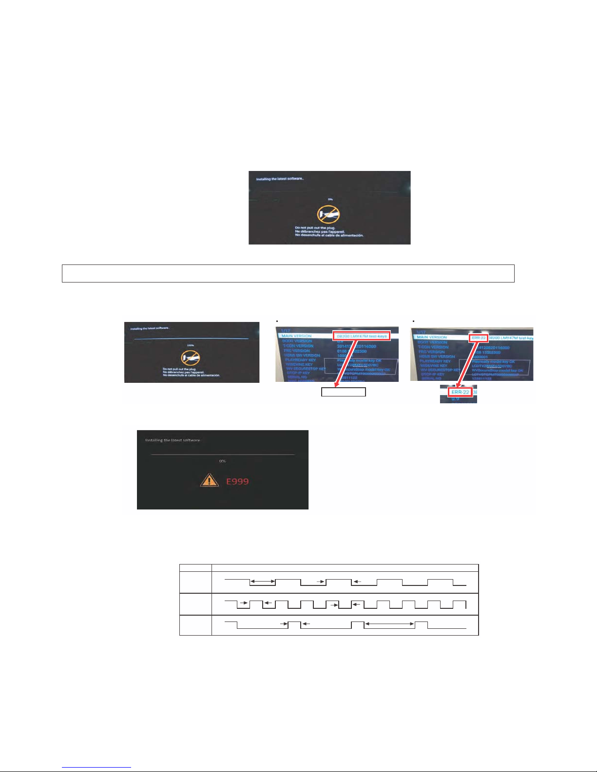
2.2.3 How to upgrade the software
1. Prepare the following items before working.
USB memory (Copy the file to a USB memory)
AC code
2. Connect USB memory.
* Insert the USB Memory for version upgrade into the service socket (USB2 or USB3 port)
3. Connect AC-code Pushing POWER key
*Upgrade software starts automatically.
*MAIN softwares are written at the same time.
*The upgrade menu is displayed after about 10second.
*Never turn off the power while upgrading.
4. It is completion if displayed, "UPGRADE SUCCESS".
*Check Upgrade condition. "100%"
5. If you failed to upgrade, "E999" is displayed.
6. Disconnect AC Plug and USB memory.
x VerUP LED pattern of USB version UP
Ver UP LED
*Please check the "LED pattern", If you are unable to check the monitor.
*LED pattern detail is please check the "VerUP LED pattern of USB version UP" below.
MAIN Ver CHECK
Case of Ver UP OK Case of Ver UP Error
If you tried upgrade some times but still E999 is displayed,
please give feedback to the service center.
WHITE
Writeing
High
Low
Completion
250ms 250ms
High
Low
Fail
200ms
High
Low
800ms
500ms 500ms
Page 11

LC50/58/65U35T
5 – 3
3. Entering and exiting the adjustment process mode
1) Before entering the adjustment process mode, the AV position RESET in the video adjustment menu.
2) While holding down the “VOL (–)” and “ENTER” keys at a time, plug in the AC cord of the main unit to turn on the power.
The letter “S” appears on the screen.
3) Next, hold down the “VOL (–)” and “CH ( )” keys at a time.
(The “VOL (–)” and “CH ( )” keys should be pressed and held until the display appears.)
Multiple lines of blue characters appearing on the display indicate that the unit is now in the adjustment process mode.
When you fail to enter the adjustment process mode (the display is the same as normal startup), retry the procedure.
4) To exit the adjustment process mode after the adjustment is done, unplug the AC cord from the outlet to make a forced shutdown. (When the
power was turned off with the remote controller, once unplug the AC cord and plug it again. In this case, wait 10 seconds or so before plugging.)
CAUTION: Use due care in handling the information described here lest your users should know how to enter the adjustment process mode. If the
settings are tampered in this mode, unrecoverable system damage may result.
4. Remote controller key operation and description of display in adjustment process mode
1) Key operation
2) Description of display
noitcnuFyek tinu niaMyek rellortnoc etomeR
CH ( / )
CH ( / )
Moving an item (line) by one (UP/DOWN)
VOL (+/–) VOL (+/–) Changing a selected item setting (+1/ –1)
Cursor (UP/DOWN) ————— Turing a page (PREVIOUS/NEXT)
Cursor (LEFT/RIGHT) ————— Changing a selected line setting (+10/ –10)
ENTER ENTER Executing a function
(1) Current page/
Total pages
1/17
09500 LMY47M TEST -KEYNOISREVNIAM
09500
_ _ _
BOOT VERSION
T-CON VERSION
No deviseNOISREVCRF
(2) Parameter
1010001NOISREVWSIMDH
KOyekledomydaeryalPYEKYDAERYALP
0C70D5AF4882VTDCLYEKENIVEDIW
WV SECURESTOP KEY WVSecureStop model key OK
1-RRE
YEKPI-PCTD
511118205ONLAIRES
0C70D5AF4882SSERDDACAM
0RORREPMAL
ERROR STANDBY CAUSE 11 00 00 00
CI + KEY
53-41-01-03-00- 00-00-16
Page 12

LC50/58/65U35T
5 – 4
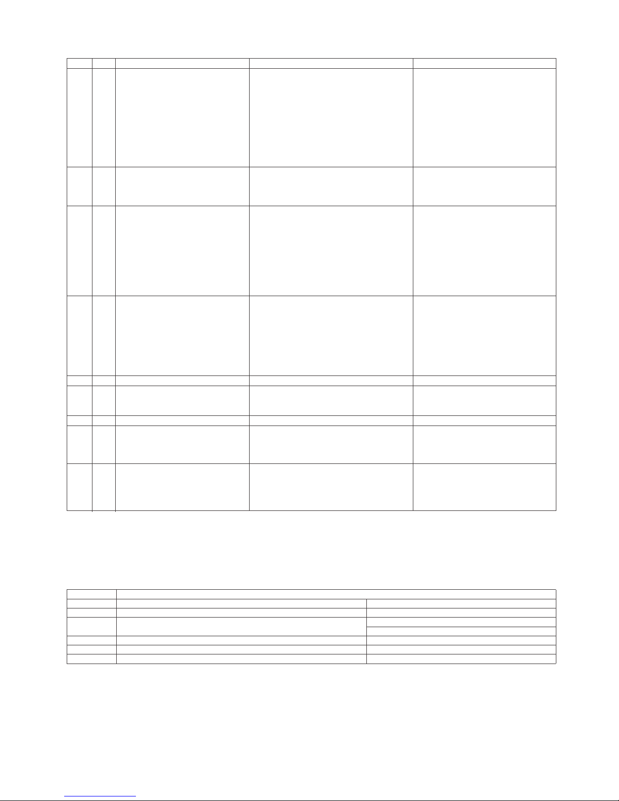
5. List of adjustment process mode menu
The character string in brackets [ ] will appear as a page title in the adjustment process menu header.
).cte ,liated tnemtsujda( skrameRnoitpircseDmetIeniLegaP
noisrev erawtfos niaMnoisreV NIAM11
2 BOOT VERSION
noisrev erawtfos rellortnoc DCLNOISREV NOC-T3
noisrev WF CRFNOISREV CRF4
5 HDMI SW VERSION
6 PLAYREADY KEY
7 WIDEVINE KEY
8 WV SECURESTOP KEY
YEK CI +9
10 SERIAL NO
11 MAC ADDRESS
rorre pmal ot eud noitanimret fo rebmuNRORRE PMAL21
13 ERROR STANDBY CAUSE
2 1 INDUSTRY INIT Initialization to factory settings
2 BACKLIGHT ACUTIME Accumulated monitor operation time
3 RESET Reset BACKLIGHT TIME
4 LAMP ERROR RESET Reset LAMP ERROR
5 ERROR STAND BY CAUSE RESET Reset ERROR STANDBY CAUSE
6 TIME COUNTER RESET
3 1 VCOM ADJ VCOM adjustment value
4 1 LEV1 Standard value 1 Adjustment gradation setting.
2 LEV2 Standard value 2
3 LEV3 Standard value 3
4 LEV4 Standard value 4
5 LEV5 Standard value 5
6 LEV6 Standard value 6
7 LEV7 Standard value 7
5 1 MG1R WB adjustment Point 1, R adjustment value Parameter for seven-point adjustment
2 MG1G WB adjustment Point 1, G adjustment value
3 MG1B WB adjustment Point 1, B adjustment value
4 MG2R WB adjustment Point 2, R adjustment value
5 MG2G WB adjustment Point 2, G adjustment value
6 MG2B WB adjustment Point 2, B adjustment value
7 MG3R WB adjustment Point 3, R adjustment value
8 MG3G WB adjustment Point 3, G adjustment value
9 MG3B WB adjustment Point 3, B adjustment value
6 1 MG4R WB adjustment Point 4, R adjustment value Parameter for seven-point adjustment
2 MG4G WB adjustment Point 4, G adjustment value
3 MG4B WB adjustment Point 4, B adjustment value
4 MG5R WB adjustment Point 5, R adjustment value
5 MG5G WB adjustment Point 5, G adjustment value
6 MG5B WB adjustment Point 5, B adjustment value
7 MG6R WB adjustment Point 6, R adjustment value
8 MG6G WB adjustment Point 6, G adjustment value
9 MG6B WB adjustment Point 6, B adjustment value
7 1 MG7R WB adjustment Point 7, R adjustment value
2 MG7G WB adjustment Point 7, G adjustment value
3 MG7B WB adjustment Point 7, B adjustment value
8 1 LO 1R WB adjustment Point 1, R adjustment value Parameter for D65 seven-point adjust-
ment
2 LO 1G WB adjustme
nt Point 1, G adjustment value
3 LO 1B WB adjustment Point 1, B adjustment value
4 LO 2R WB adjustment Point 2, R adjustment value
5 LO 2G WB adjustment Point 2, G adjustment value
6 LO 2B WB adjustment Point 2, B adjustment value
7 LO 3R WB adjustment Point 3, R adjustment value
8 LO 3G WB adjustment Point 3, G adjustment value
9 LO 3B WB adjustment Point 3, B adjustment value
Page 13
LC50/58/65U35T
5 – 5
For the system spec, error"0x11" is always recorded after Factory Reset execution. It is not recorded as problem so that please be careul when you
find out.
-tsujda tniop-neves 56D rof retemaraPeulav tnemtsujda R ,4 tnioP tnemtsujda BW4
R
OL19
ment
eulav tnemtsujda G ,4 tnioP tnemtsujda BW4 G OL2
eulav tnemtsujda B ,4 tnioP tnemtsujda BW4 B OL3
eulav tnemtsujda R ,5 tnioP tnemtsujda BW5 R OL4
eulav tnemtsujda G ,5 tnioP tnemtsujda BW5 G OL5
eulav tnemtsujda B ,5 tnioP tnemtsujda
BW5 B OL6
eulav tnemtsujda R ,6 tnioP tnemtsujda BW6 R OL7
eulav tnemtsujda G ,6 tnioP tnemtsujda BW6 G OL8
eulav tnemtsujda B ,6 tnioP tnemtsujda BW6 B OL9
10 1 LO 7R WB adjustment Point 7, R adjustment value Parameter for D65 seven-point adjust-
ment
2 LO 7G WB adjustment Point 7, G adjustment value
3 LO 7B WB adjustment Point 7, B adjustment value
11 1 CD MIN Input parameterfor gamma adjustment
2 CD MID1
3 CD MID2
4 CD MID3
5 CD MID4
6 CD MID5
7 CD MID6
8 CD MID7
9 CD MAX
12 1 VAL1 Parameter for gamma adjustment
2VAL2
3VAL3
4VAL4
5VAL5
6VAL6
7VAL7
8 GAMMA ADJ TEMP
13 1 MONITOR TIME OUT
14 1 LCD TEST PATTERN1
2 LCD TEST PATTERN2
3 TV TEST PATTERN
15 1 DUMMY
16 1 USB BACKUP Save the parameter of WB and Gamma
data as USB data file.
2 USB RESTORE Restore the parameter of WB and
Gamma data from USB data file.
17 1 MODEL Set model name.
2 PANEL SIZE
Set panel size.
3 VOLUME TYPE Set speaker volume type.
Error Standby Cause
Outline: Communication/Power failure detected by the monitor microprocessor is stored in EEPROM, and last 4 abnormal
can be confirmed in the Process mode A.
Location: Page 1 of the process mode A: MONITOR ERR CAUSE. “0” if there is no error. It is cleared to 0 on the last page of
the process mode A.
Display Error description
0x11 Regular communication time-out ---0x16 Backlight error Refer to Troubleshooting Table
0x1A Monitor temperature error - Check TV setting environment.
- Check the other monitor (ref No.)
0x1E DET_13V failure Check 13V power line.
0x1F DET_VCORE failure Check CPU core power line.
0x21 DET_POW_T failure Check T-CON or FRC power line.
Page Line Item Description Remarks (adjustment detail, etc.)
4 DESTINATION Set destination.
Page 14
LC50/58/65U35T
5 – 6
6. Special features
* Error Standby Cause(Page 1/17)
Display of a cause (code) of the last standby
The cause of the last standby is recorded in EEPROM whenever possible.
Checking this code will be useful in finding a problem when you repair the troubled set.
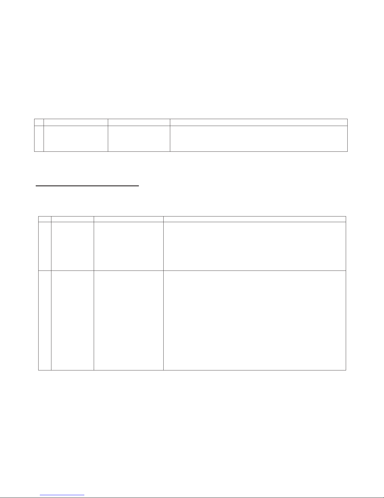
7. Writing the microprocessor software
7.1. Writing the main microprocessor software and monitor microprocessor software
(Main PWB: QPWBXG506WJ**)
Adjustment item Adjustment conditions Adjustment procedure
1 Writing the main micropro-
cessor software and monitor microprocessor software
<Main PWB>
Checker process
Checking the file version
1) Only boot part, write firmware with Gang Programmer.
IC: RH-iXD775WJQZQ (IC3303)
2) Confirm the software version and operation verification by test checker.
8.1 . WHITE BALANCE ADJUSTMENT/ GAMMA ADJUSTMENT
ERUDECORP NOITIDNOC METI
1 Setting
Brightness㸸MAX (+16)
AV MODE: DYNAMIC
Active Backlight: off
OPC: off
*Set the luminance
meter at the center
of the screen
1. TV is set to below condition.
AV Mode : DYNAMIC
Backlight : +16
Active Backlight : OFF
2. Connect White Balance Adjustment jig to TV set.
2 [1] Auto
Adjustment
[DYNAMIC]
Adjustment
[Command]
Adjustment mode
KRSW0001
KKT10037
Multi point adjustment
mode
MSET0001
Point 7
LEV70229
MG7G****
MG7B****
MG7R****
[Adjustment procedure]
1. Using R/C, set the LCD TV to adjustment mode.
[DYNAMIC] Adjustment
2. Set the strongest color as fixed color, minus adjust by
changing the value by 4 at a time to be the reference
value, adjust RGB at MG7***** command.
3. For Point 6, set the correction value of G (1840 x Point 7
G val
ue/3664)
(a fraction is rounded up), change the value
by 4 at a time to be the reference value, adjust RB.
4. For Point 5, set the correction value of G (640 x Point 7 G
value/3664) (a fraction is rounded up), change the value
by 4 at a time to be the reference value, adjust RB.
5. For point 4 to 1 : no use, all set to 0
6. Write the adjustment value at MSET0003 command.
*Initial value of RGB at Point 7 = Setting level 3664
*Initial value of RGB at Point 5,6
= correction value of G of e
ach point
LCD TV ADJUSTMENT ITEM
8.White Balance adjustment.
Page 15

LC50/58/65U35T
5 – 7
Point 6
LEV60115
MG6G****
MG6B****
MG6R****
Point 5
LEV50040
MG5G****
MG5B****
MG5R****
Point 4
LEV40000
MG4G0000
MG4B0000
MG4R0000
Point 3
LEV30000
MG3G0000
MG3B0000
MG3R0000
Point 2
LEV20000
MG2G0000
MG2B0000
MG2R0000
Point 1
LEV10000
MG1G0000
MG1B0000
MG1R0000
W/B adj. value data
input
MSET0003
[Adjustment value]
Based on Teaching set
After adjust luminance spec: Min 280cd/m2
[Reference value for adjustment]
Equipment : Luminance meter [Minolta CS-2000]
(DYNAMIC MODE)
Level
Referenc
e value
Adjustment
Spec .
Inspection
Spec .
Point 7 3664
x=0.2685
±0.0010 ±0.0020
y=0.2670
Point 6 1840
x=0.2685
±0.0015 ±0.0030
y=0.2670
Point 5 640
x=0.2685
±0.0045 ±0.0090
y=0.2670
Point 4 0
NO USE
Point 3 0
Point 2 0
Point 1 0
Remarks
For inspection set condition
AV MODE : [DYNAMIC]
Monochrome : ON
Active Backlight : OFF
Aging time : Minimum 60 min.
Page 16

LC50/58/65U35T
5 – 8
8.2) GAMMA 2.2 Adjustment
ERUDECORP NOITIDNOC METI
1 Setting Backlight : MAX(+16)
Active Backlight: Off
Regarding the details of white balance adjustment procedure, refer
to the latest Gamma adjustment spec.
1. Confirm the set condition.
2. Connect the jig.
3. Place the probe at the White Balance adjustment screen
location.
2 Auto
Adjustment
[Command]
Adjustment Mode
KRSW0001
KKT10037
Multi Point
Adjustment Mode
MSET0001
Measurement Pattern
LEV00000
LEV50040
LEV60115
LEV70229
LEV80255
Adjustment Value
Input
GCCX****
(X is Level, **** is
adjustment value
MIN X=0, MAX X=8)
Input Data
GCST0001
࣭Set the MIN adjustment level, and measure the luminance.
Measured luminance is increased 100 times, set the integer as
adjustment value (a fraction is rounded up).
࣭Set the MID5 adjustment level, and measure the luminance.
Measured luminance is increased 10 times,
set the integer as
adjustment value (a fraction is rounded up).
࣭Set the MID6 adjustment level, and measure the luminance.
Measured luminance is increased 10 times,
set the integer as
adjustment value (a fraction is rounded up).
࣭Set the MID7 adjustment level, and measure the luminance.
Measured luminance is increased 10 times,
set the integer as
adjustment value (a fraction is rounded up).
࣭Set the MAX adjustment level, and measure the luminance.
Measured luminance is increased 10 times,
set the integer as
adjustment value (a fraction is rounded up).
[Adjustment Level] (Adjustment level is determined before sales
approval set making)
MIN ADJ LEVEL 0 /255 LEVEL
MID1 ADJ LEVEL 0 /255 LEVEL
MID2 ADJ LEVEL 0 /255 LEVEL
MID3 ADJ LEVEL 0 /255 LEVEL
MID4 ADJ LEVEL 0 /255 LEVEL
MID5 ADJ LEVEL 40 /255 LEVEL
MID6 ADJ LEVEL 115 /255 LEVEL
MID7 ADJ LEVEL 229 /255 LEVEL
MAX ADJ LEVEL 255 /255 LEVEL
3 Adjustment
Check
Check that the adjustment result is no problem.
࣭Check that the Gamma adjustment value is in spec.
VAL Spec 100±15
Page 17

LC50/58/65U35T
5 – 9
9. KEY WRITING
(1) MAC Address Data Input (Main PWB: QPWBXG506WJN1)
Please refer to Caution Item for Production
(2) Widevine, PlayReady, WVSecureStop
Key Data Input (Main PWB: QPWBXG506WJN1)
Please refer to Caution Item for Production
(3) Serial No. (Main PWB: QPWBXG506WJN1)
Please refer to Caution Item for Production
Display format (example)
1/17
MAIN VERSION
BOOT VERSION
T-CON VERSION
FRC VERSION
HDMI SW VERSION
PLAYREADY KEY
WIDEVINE KEY
WV SECURESTOP KEY
DTCP-IP KEY
CI+ KEY
SERIAL NO
MAC ADDRESS
LAMP ERROR
ERROR STANDBY CAUSE
09500 LMY47M test-keys
0.95
------
No device
1000101
Playready model key OK
LCDTV2884FAB73D41
WVSecureStop model key OK
------
53-41-01-03-00 00-00-3A
506711119
2884FAB73D41
0
00 00 00 00
Page 18

LC50/58/65U35T
5 – 10
Writing the Panel size, volume, type and destination
1) Enter the adjustment process mode
2) Point the cursor to [PANEL SIZE]
3) Select Panel Size and press [enter] key
4) “OK” is displayed
5) Point the cursor to [VOLUME TYPE]
6) Select Volume Type and press [enter] key
7) “OK” is displayed
8) Point the cursor to [INDUSTRY INITIAL]
9) Select Destination and press [enter] key
10) “OK” is displayed
Volume
Type
50U35T 58U35T 65U35T
0 1 2
10. FACTORY SETTING
AC power is plug off after shipment setting is done.
Caution: Do not plug on again after shipment setting is done. If do, please re-do the shipment setting.
ERUDECORP NOITIDNOC METI
Factory setting AC power off to exit the
factory setting.
࣭Move cursor to [INDUSTRY INIT] on 2
nd
page, change the option from
NO to YES, then press [ENT].
Version confirmation screen is displayed on the green screen, if
[SUCCESS] is displayed on the top side, it is complete.
࣭Power AC OFF.
The followings are initialised to factory setting
1) User Setting
2) Channel Data (broadcast frequencies etc.)
3) Password Setting Value
4) Operating Hours
5) Standby Cause
6) Auto Installation Flag
Page 19

LC50/58/65U35T
5 – 11
11. SOFTWARE VERSION
Confirmation on Software version will be done during meeting.
egakcaP erawtfoS ledoM
LC-65U35T
LC-58U35T
LC-50U35T
upgrade_loader_Malacca_XXXXX.pkg
Main Software Filename : XXXXX is Software version
If any changes of software, will be informed by MARUHEN
Page 20

LC50/58/65U35T
5 – 12
12. Writing the inch and model name and volume type on EEPROM.
1. Enter the adjustment process mode.
2. Point the cursor to [MODEL](Page 17/17)
3. Select model(U35T), and press [Enter] key.
4. “OK” is displayed.
5. Point the cursor to [PANEL SIZE] (Page 17/17).
6. Select size(65,58,50) and press [Enter] key.
7. Moments later image is displayed.
8. Point the cursor to [Volume Type]
9. Select Volume Type, and press [Enter]key.
10."OK" is displayed.
11.Turn off power
12.Turn on power
Page 21

LC50/58/65U35T
5 – 13
13. How to write Serial Number
After change New Main board, change “Model and Panel Size” and write “Serial Number”.
13.1. Change Model and Panel Size and Volume type.
1. Enter the adjustment process mode.
2. Point the cursor to [MODEL NAME].
3. Select model, and press [Enter] key.
4. “OK” is displayed.
5. Point the cursor to [PANEL SIZE].
6. Select Panel Size and press [Enter] key.
7. Moments later image is displayed.
8. Point the cursor to [Volume Type]
9. Select Volume Type, and press [Enter]key.
10."OK" is displayed.
11.Turn off power.
12.Turn on power.
Example
VOLUME TYPE
50U35T
58U35T
65U35T
0 1 2
U35T
Page 22

LC50/58/65U35T
5 – 14
13.2. Write Serial Number
13.2.1 Get ready before you start
• USB Memory of 128MB or higher capacity.
• PC running on Windows 98/98SE/ME/2000/XP/Vista/Win7/Win8 operating system.
• USB Memory reader/writer or PC with a USB port.
• The file system of a USB memory is FAT. (FAT32 supports)
• Use the USB memory without other functions. (lock and memory reader...etc)
• Use the USB memory without other files.
• Check Serial Number. (Model Label)
14.2.2 Preparations
To write serial number, it is necessary to get ready the USB Memory before you start.
Follow the steps below and create the USB Memory for writing serial number.
Copy the file *********.SEN to the root directory (folder) of the USB Memory.
NOTE: SEN file name is Serial No (9-digit)
e.g.) 407811119.SEN => Serial No: 407811119
Example: LC-65U35T
Page 23

LC50/58/65U35T
6 – 1
CHAPTER 6. TROUBLESHOOTING
TABLE
[1] TROUBLESHOOTING TABLE
[1] Failure diagnosis by LED in front of cabinet
[2] LED flashing specification at the time of an error (POWER LED used)
1. Display method
• Since only the POWER LED can be used, slow flashing and fast flashing are combined.
• After recovering from an error, if the same error cannot be generated again, refer to MONITOR ERR CAUSE on the adjustment process mode.
2. LED flashing method
Error flashing
Table 1. Concrete flashing pattern
*2: They depend on the system. Power supply error is defined from product to product.
*3: For details, refer to ERROR STANDBY CAUSE on the adjustment process mode.
Item
Detail display
Cause
Slow flashing Fast flashing
Inverter/Lamp system failure Flashes once Flashes once Lamp error
Power PWB failure Flashes twice Flashes twice Power supplly error (*2) UR+13V error
rorre )V3.3D(EROCV )2*( rorre yllppus rewoPsemit 3 sehsalF ).cte ,eruliaf rewoP(
Main PWB failure
(Communitacion failure, etc.)
Flashes 3 times Flashes 3 times Regular communication error
Others
Flashes 4 times
Flashes once Temperature error
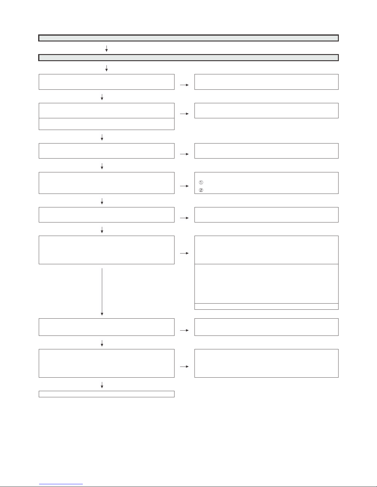
No
Yes
No
Yes
No
Yes
Is the POWER LED flashing?
START
Is the POWER LED lighting
When AC plug on?
Is the Backlight lighting?
Check "[2] LED flashing specification at the time of an error (POWER LED used)".
Check Power-Unit and AC-cable.
Check "
LED Backlight does not turn on.".
Check "
Picture does not display.".
1600ms
300ms
100ms
400ms
400ms
1600ms
OFF
ON
POWER LED
Page 24

LC50/58/65U35T
6 – 2
3. New method
LED flashing timing chart at the time of an error
1) Inverter/Lamp failure details (Flashes slowly once and flashes fast) Note
2) Power failure details (Flashes slowly twice and flashes fast) Note
3) Communication failure details (Flashes slowly 3 times and flashes fast) Note
4) Other failure details (Flashes slowly 4 times and flashes fast) Note
noitarepo DEL REWOPepyt rorrE
Pins are monitor microcomputer pins unless other
-wise specified.
Lamp failure
Flashes fast once
H: On
L: Off
LAMP_ERR: failure (H). Inverter/Lamp error is detected.
Note that after five detection counts, the lamp cannot be
activated except in the IgnoreError mode.
Accumulated counts are cleared to 0 by the setting in the
LAMP ERROR RESET on the adjustment process mode.
noitarepo DEL REWOPepyt rorrE
Pins are monitor microcomputer pins unless other
-wise specified.
13V error
Main 13V failure
Flashes fast twice
H: On
L: Off
DET_V12 failure (L). Main 13V is not applied.
VCORE erro
r
D3.3V failure
Flashes fast 3 times
H: On
L: Off
DET_VCORE failure (L). D3.3V is not applied.
noitarepo DEL REWOPepyt rorrE
Pins are monitor microcomputer pins unless other
-wise specified.
Regular communication failure
Flashes fast 3 times
H: On
L: Off
Watchdog reboot consecutively occurred 4 times without keeping stable state 3 minutes.
o Main CPU operation failure
noitarepo DEL REWOPepyt rorrE
Pins are monitor microcomputer pins unless other
-wise specified.
Monitor temperature
failure
Flashes fast once
H: On
L: Off
If the panel temperature is 60qC or more for 15 seconds
or more in a row, CAUTION appears on the OSD
(flashes in red in the lower right screen).
If the panel temperature is 60qC or more for 25 seconds
or more in a row, error standby is activated.
ces6.1sm004sm001
Page 25

LC50/58/65U35T
6 – 3
[3] TROUBLESHOOTING TABLE
If it is not an error of power supply/LED driver,
It is start-up in the lamp error disregard mode.
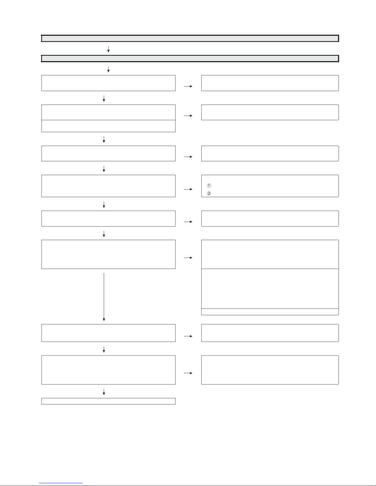
?trats uoy oD
YES
When main unit is replaced , does it start
normally?
NO
When LCD control unit is replaced
,does it start normally?
NO
When the parts in the panel can be
replaced.
o Replace all LED-bars in the panel module.
When the parts in the panel cannot be
replaced.
oReplace panel module.
YES
YES
.tinu lartnoc DCL ecalpeR .tinu niam ecalpeR
If it is not an error of power supply/LED driver,
It is start-up in the lamp error disregard mode.
?trats uoy oD
NO
When power supply unit is
replaced , does it start normally?
NO
When main unit is
replaced , does it start
normally?
NO
When LCD control unit is
replaced ,does it start normally?
NO
When the parts in the panel
can be replaced.
oReplace all LED-bars in
the panel module.
When the parts in the panel
cannot be replaced.
oReplace panel module.
SEYSEYSEY
Replace power supply unit. Replace main unit. Replace LCD contral unit.
Page 26

LC50/58/65U35T
6 – 4
Trouble Shooting Panel Module
When main unit is replaced, does
screen display normally?
NO
When power unit is replaced, does
screen display normally?
NO
Replace Panel Module.
SEYSEY
. Power unitecalpeR
. e main unit calpeR
Page 27
LC50/58/65U35T
6 – 5
No video (1)-1
HDMI:No external input video [HDMI1]
Is HDMI1 selected on the input select menu screen? NO Select HDMI1 on the input select menu screen for the right input sig-
nal.
YES
eht kcehCON?noitcnuf noitceted GULP TOH eht seoD line between the pin(18) of SC1501 and the pin(102) of
IC2502.
Does the DDC5V signal come from pin(18) of SC1501 to
pin(102) of IC2502(HDMI-SW)?
YES
Does the HPD signal come from pin(142) of IC2502 to pin(19) of
SC1501?
NO Check the line between the pin(19) of SC1501 and the pin(142) of
IC2502.
YES
Is IC2502(HDMI-SW) accessed by I2C, with HDMI connected, to
read the DDC-I2C SCL/SDA data?
NO
Check the DDC-I2C line and its peripheral circuits..
SC1501 pin(15)(SCL), pin(16)(SDA)
IC2502 pin(101)(SCL), pin(99)(SDA)
YES
Does the HPD signal come from pin(F31/F30) of IC3303 to
pin(110/113) of IC2502?
NO Check the line between the pin(F31/F30) of IC3303 and the pin(110/
113) of IC2502.
YES
Are there the TMDS signals at input pins of IC3301(CPU)?
NO
Check the TMDS line (between SC1501 and IC2502) and its peripheral circuits.
[IC2502 TMDS input pins]
pin(145/146)(CLK-/+), pin(149/150)(D0-/+),
pin(151/152)(D1-/+), pin(153/154)(D2-/+).
YES
Check the TMDS line (between IC2502 and IC3303) and its peripheral circuits.
[IC3303 TMDS input pins]
pin(B24/A24)(TMDS0_CLK-/+), pin(D23/C23)(TMDS0_D0-/+),
pin(D22/C22)(TMDS0_D1-/+), pin(B22/A22)(TMDS0_D2-/+).
pin(B21/A21)(TMDS1_CLK-/+), pin(B20/A20)(TMDS1_D0-/+),
pin(B19/A19)(TMDS1_D1-/+), pin(B18/A18)(TMDS1_D2-/+).
Check SC1501, IC2502, IC3303 and its peripheral circuits.
Is the T-CON PWB connected?
V_LOCKN pin(26) of SC3802 become Low if there is no problem
in the connection.
NO
Check the T-CON PWB and harness.
Check IC3303 and SC3802 and their peripheral circuits in Main
PWB.
YES
Are the V-By-One HS signal input to the pin of SC3802?
V_VBO_TX_1+/-(23/24pin), V_VBO_TX_2+/-(20/21pin),
V_VBO_TX_3+/-(17/18pin),
V_VBO_TX_4+/-(14/15pin), V_VBO_TX_5+/-(11/12pin),
V_VBO_TX_6+/-(8/9pin), etc
NO
Check IC3303 and its peripheral circuits.(IC3501/IC3502/IC3503,
etc.)
YES
Check the panel module and harness.
Page 28
LC50/58/65U35T
6 – 6
No video (1)-2
HDMI:No external input video [HDMI2]
Is HDMI2 selected on the input select menu screen? NO Select HDMI2 on the input select menu screen for the right input
signal.
YES
fo )79(nip eht dna 2051CS fo )81(nip eht neewteb enil eht kcehCON?noitcnuf noitceted GULP TOH eht seoD
IC2502.
Does the DDC5V signal come from pin(18) of SC1502 to pin(97)
of IC2502(HDMI-SW)?
YES
Does the HPD signal come from pin(127) of IC2502 to pin(19) of
SC1501?
NO Check the line between the pin(19) of SC1502 and the pin(127) of
IC2502.
YES
Is IC2502(HDMI-SW) accessed by I2C, with HDMI connected, to
read the DDC-I2C SCL/SDA data?
NO
Check the DDC-I2C line and its peripheral circuits..
SC1502 pin(15)(SCL), pin(16)(SDA)
IC2502 pin(96)(SCL), pin(95)(SDA)
YES
Does the HPD signal come from pin(F31/F30) of IC3303 to
pin(110/113) of IC2502?
NO Check the line between the pin(F31/F30) of IC3303 and the
pin(110/113) of IC2502.
YES
Are there the TMDS signals at input pins of IC3301(CPU)?
NO
Check the TMDS line (between SC1502 and IC2502)
and its
peripheral circuits.
[IC2502 TMDS input pins]
pin(130/131)(CLK-/+), pin(134/135)(D0-/+),
pin(136/137)(D1-/+), pin(138/139)(D2-/+).
YES
Check the TMDS line (between IC2502 and IC3303) and its
peripheral circuits.
[IC3303 TMDS input pins]
pin(B24/A24)(TMDS0_CLK-/+), pin(D23/C23)(TMDS0_D0-/+),
pin(D22/C22)(TMDS0_D1-/+), pin(B22/A22)(TMDS0_D2-/+).
pin(B21/A21)(TMDS1_CLK-/+), pin(B20/A20)(TMDS1_D0-/+),
pin(B19/A19)(TMDS1_D1-/+), pin(B18/A18)(TMDS1_D2-/+).
Check SC1502, IC2502, IC3303 and its peripheral circuits.
Is the T-CON PWB connected?
V_LOCKN pin(26) of SC3802 become Low if there is no problem
in the connection.
NO
Check the T-CON PWB and harness.
Check IC3303 and SC3802 and their peripheral circuits in Main
PWB.
YES
Are the V-By-One HS signal input to the pin of SC3802?
V_VBO_TX_1+/-(23/24pin), V_VBO_TX_2+/-(20/21pin),
V_VBO_TX_3+/-(17/18pin),
V_VBO_TX_4+/-(14/15pin), V_VBO_TX_5+/-(11/12pin),
V_VBO_TX_6+/-(8/9pin), etc
NO
Check IC3303 and its peripheral circuits.(IC3501/IC3502/IC3503,
etc.)
YES
Check the panel module and harness.
Page 29

LC50/58/65U35T
6 – 7
No video (1)-3
HDMI:No external input video [HDMI3]
Is HDMI3 selected on the input select menu screen? NO Select HDMI3 on the input select menu screen for the right input signal.
YES
eht kcehCON?noitcnuf noitceted GULP TOH eht seoD line between the pin(18) of SC1503 and the pin(86) of
IC2502.
Does the DDC5V signal come from pin(18) of SC1503 to
pin(86) of IC2502(HDMI-SW)?
YES
Does the HPD signal come from pin(85) of IC2502 to pin(19) of
SC1503?
NO Check the line between the pin(19) of SC1503 and the pin(85) of
IC2502.
YES
Is IC2502(HDMI-SW) accessed by I2C, with HDMI connected,
to read the DDC-I2C SCL/SDA data?
NO
Check the DDC-I2C line and its peripheral circuits..
SC1503 pin(15)(SCL), pin(16)(SDA)
IC2502 pin(84)(SCL), pin(83)(SDA)
YES
Does the HPD signal come from pin(F31/F30) of IC3303 to
pin(110/113) of IC2502?
NO Check the line between the pin(F31/F30) of IC3303 and the pin(110/
113) of IC2502.
YES
Are there the TMDS signals at input pins of IC3301(CPU)?
NO
Check the TMDS line (between SC1503 and IC2502) and its peripheral
circuits.
[IC2502 TMDS input pins]
pin(67/68)
(CLK-/+), pin(71/72)(D0-/+),
pin(73/74)(D1-/+), pin(75/76)(D2-/+).
YES
Check the TMDS line (between IC2502 and IC3303) and its peripheral
circuits.
[IC3303 TMDS input pins]
pin(B24/A24)(TMDS0_CLK-/+), pin(D23/C23)(TMDS0_D0-/+),
pin(D22/C22)(TMDS0_D1-/+), pin(B22/A22)(TMDS0_D2-/+).
pin(B21/A21)(TMDS1_CLK-/+), pin(B20/A20)(TMDS1_D0-/+),
pin(B19/A19)(TMDS1_D1-/+), pin(B18/A18)(TMDS1_D2-/+).
Check SC1503, IC2502, IC3303 and its peripheral circuits.
Is the T-CON PWB connected?
V_LOCKN pin(26) of SC3802 become Low if there is no problem in the connection.
NO
Check the T-CON PWB and harness.
Check IC3303 and SC3802 and their peripheral circuits in Main PWB.
YES
Are the V-By-One HS signal input to the pin of SC3802?
V_VBO_TX_1+/-(23/24pin), V_VBO_TX_2+/-(20/21pin),
V_VBO_TX_3+/-(17/18pin),
V_VBO_TX_4+/-(14/15pin), V_VBO_TX_5+/-(11/12pin),
V_VBO_TX_6+/-(8/9pin), etc
NO
Check IC3303 and its peripheral circuits.(IC3501/IC3502/IC3503, etc.)
YES
Check the panel module and harness.
Page 30

LC50/58/65U35T
6 – 8
No video (1)-4
HDMI:No external input video [HDMI4]
Is HDMI4 selected on the input select menu screen? NO Select HDMI4 on the input select menu screen for the right input sig-
nal.
YES
eht kcehCON?noitcnuf noitceted GULP TOH eht seoD line between the pin(18) of SC1503 and the pin(81) of
IC2502.
Does the DDC5V signal come from pin(18) of SC1504 to pin(81)
of IC2502(HDMI-SW)?
YES
Does the HPD signal come from pin(80) of IC2502 to pin(19) of
SC1501?
NO Check the line between the pin(19) of SC1503 and the pin(80) of
IC2502.
YES
Is IC2502(HDMI-SW) accessed by I2C, with HDMI connected, to
read the DDC-I2C SCL/SDA data?
NO
Check the DDC-I2C line and its peripheral circuits..
SC1503 pin(15)(SCL), pin(16)(SDA)
IC2502 pin(79)(SCL), pin(78)(SDA)
YES
Does the HPD signal come from pin(F31/F30) of IC3303 to
pin(110/113) of IC2502?
NO Check the line between the pin(F31/F30) of IC3303 and the pin(110/
113) of IC2502.
YES
Are there the TMDS signals at input pins of IC3301(CPU)?
NO
Check the TMDS line (between SC1503 and IC2502) and its peripheral circuits.
[IC2502 TMDS input pins]
pin(54/55)(CLK-/+), pin(58/59)(D0-/+),
pin(60/61)(D1-/+), pin(62/63)(D2-/+).
YES
Check the TMDS line (between IC2502 and IC3303) and its peripheral circuits.
[IC3303 TMDS input pins]
pin(B24/A24)(TMDS0_CLK-/+), pin
(D23/C23)(TMDS0_D0-/+),
pin(D22/C22)(TMDS0_D1-/+), pin(B22/A22)(TMDS0_D2-/+).
pin(B21/A21)(TMDS1_CLK-/+), pin(B20/A20)(TMDS1_D0-/+),
pin(B19/A19)(TMDS1_D1-/+), pin(B18/A18)(TMDS1_D2-/+).
Check SC1503, IC2502, IC3303 and its peripheral circuits.
Is the T-CON PWB connected?
V_LOCKN pin(26) of SC3802 become Low if there is no problem
in the connection.
NO
Check the T-CON PWB and harness.
Check IC3303 and SC3802 and their peripheral circuits in Main PWB.
YES
Are the V-By-One HS signal input to the pin of SC3802?
V_VBO_TX_1+/-(23/24pin), V_VBO_TX_2+/-(20/21pin),
V_VBO_TX_3+/-(17/18pin),
V_VBO_TX_4+/-(14/15pin), V_VBO_TX_5+/-(11/12pin),
V_VBO_TX_6+/-(8/9pin), etc
NO
Check IC3303 and its peripheral circuits.(IC3501/IC3502/IC3503,
etc.)
YES
Check the panel module and harness.
Page 31

LC50/58/65U35T
6 – 9
No video (2)
COMPONENT:No external input video [Component/VIDEO]
Is Component/VIDEO selected on the input select menu
screen?
Is the Input Settings for the input signal?
NO
Select "Devices" - "Component/VIDEO" - "Component/VIDEO
select" - "Conponent" of user menu. Then, select "Switch to device"
on this menu.
YES
Does the COMP1_PLUG of Component/VIDEO detection function?
Check the line between pin(2) of input terminal(J504) and
pin(AM21) of IC3303(CPU).
J504:pin(2)
IC3303:pin(AM21)
Are there the COMPONENT video signal inputs at
pins(L36)(Y)/(K36)(Pb) and (J37)(Pr) of IC3303(CPU)?
NO
Check the line between the input terminals of J504 and IC3301.
J504 pin(3)(Y), pin(5)(Pb), pin(7)(Pr)
AIC3303 pins(L36)(Y), (K36)(Pb), (J37)(Pr)
YES
Is the T-CON PWB connected?
V_LOCKN pin(26) of SC3802 become Low if there is no problem in the connection.
NO
Check the T-CON PWB and harness.
Check IC3303 and SC3802 and their peripheral circuits in Main
PWB.
YES
Are the V-By-One HS signal input to the pin of SC3802?
V_VBO_TX_1+/-(23/24pin), V_VBO_TX_2+/-(20/21pin),
V_VBO_TX_3+/-(17/18pin),
V_VBO_TX_4+/-(14/15pin), V_VBO_TX_5+/-(11/12pin),
V_VBO_TX_6+/-(8/9pin), etc
NO
Check IC3303 and its peripheral circuits.(IC3501/IC3502/IC3503,
etc.)
YES
Check the panel module and harness.
Page 32

LC50/58/65U35T
6 – 10
No video (5)
No video at UHF/VHF and digital broadcast signal reception
Is the specified TV signal selected on the input select menu
screen?
Are there the IF signal at input pins(P6/P7)(TUN_IFN/P) of
IC3303(CPU)?
NO Check the IF signal line between IC3303 and TU1105, and their
peripheral circuits.
YES
Check the Tuner I2C lines.
TU1105:pin(10)(TUN_SCL), pin(11)(TUN_SDA)
IC3303:pin(E18), pin(F18)
Is the T-CON PWB connected?
V_LOCKN pin(26) of SC3802 become Low if there is no problem in the connection.
NO
Check the T-CON PWB and harness.
Check IC3303 and SC3802 and their peripheral circuits in Main
PWB.
YES
Are the V-By-One HS signal input to the pin of SC3802?
V_VBO_TX_1+/-(23/24pin), V_VBO_TX_2+/-(20/21pin),
V_VBO_TX_3+/-(17/18pin),
V_VBO_TX_4+/-(14/15pin), V_VBO_TX_5+/-(11/12pin),
V_VBO_TX_6+/-(8/9pin), etc
NO
Check IC3303 and its peripheral circuits.(IC3501/IC3502/IC3503,
etc.)
YES
Check the panel module and harness.
Page 33

LC50/58/65U35T
6 – 11
No video (5)
No video at UHF/VHF and digital broadcast signal reception
Is the specified TV signal selected on the input select menu
screen?
Are there the IF signal at input pins(P6/P7)(TUN_IFN/P) of
IC3303(CPU)?
NO Check the IF signal line between IC3303 and TU1105, and their
peripheral circuits.
YES
Check the Tuner I2C lines.
TU1105:pin(10)(TUN_SCL), pin(11)(TUN_SDA)
IC3303:pin(E18), pin(F18)
Is the T-CON PWB connected?
V_LOCKN pin(26) of SC3802 become Low if there is no problem in the connection.
NO
Check the T-CON PWB and harness.
Check IC3303 and SC3802 and their peripheral circuits in Main
PWB.
YES
Are the V-By-One HS signal input to the pin of SC3802?
V_VBO_TX_1+/-(23/24pin), V_VBO_TX_2+/-(20/21pin),
V_VBO_TX_3+/-(17/18pin),
V_VBO_TX_4+/-(14/15pin), V_VBO_TX_5+/-(11/12pin),
V_VBO_TX_6+/-(8/9pin), etc
NO
Check IC3303 and its peripheral circuits.(IC3501/IC3502/IC3503,
etc.)
YES
Check the panel module and harness.
Page 34

LC50/58/65U35T
6 – 12
No audio (1)
Component/VIDEO No audio.
Is Component/VIDEO selected on the input select menu screen?
NO
Refer to "COMPONENT:No external input
video [Component/VIDEO]"
or "COMPOSITE:No external input video
[Component/VIDEO]".
YES
Is selecting "Fixed" of "Audio Out > Stereo Minijack > Output Select" on the setting
menu screen ?
NO Set the audio output to "Fixed".
YES
Does the audio signal come from pins(2)(L) and (4)(R) of input terminal(J502) to
pins(C37)(L) and (A36)(R) of IC3303(CPU)?
NO Check the line between J502 and IC3303.
YES
About the L/R speakers.
Does the digital audio signal come from pins(AP36/AM31/AN30/AN31)(SP_MCLK/
SP_BCLK/SP_LRCLK/SP_LR_DAT) of IC3303(CPU) to pins(5/6/7/8)(SP_MCLK/
SP_LR_DAT/SP_BCLK/SP_LRCLK) of IC1701(Audio AMP) ?
About the Subwoofer speaker.
Does the digital audio signal come from pins(AP36/AM31/AN30/AM30)(SP_MCLK/
SP_BCLK/SP_LRCLK/SP_WF_DAT) of IC3303(CPU) to pins(5/6/7/8)(SP_MCLK/
SP_WF_DAT/SP_BCLK/SP_LRCLK) of IC1801(Audio AMP) ?
NO
Check the line between IC3303 and IC1701 /
IC1801, and their paripheral circuits.
YES
About the L/R Speakers.
Does the audio signal come from pins (10/14/26/30) of IC1701 (Audio AMP) to pin
(6/5/4/3) of P1702 (connector for speaker)?
About the Subwoofer speaker.
Does the audio signal come from pins (10/14/26/30) of IC1801 (Audio AMP) to pin
(1/2) of P1702 (connector for speaker)?
NO
Check IC1701 / IC1801 and its paripheral circuits.
YES
About the L/R Speakers.
Check the connector (P1702) L/R speakers
and their peripheral circuits.
About the Subwoofer Speaker.
Check the connector (P1702) L/R speakers and their peripheral circuits.
Page 35

LC50/58/65U35T
6 – 13
No audio (2)
[HDMI analog audio input] HDMI3 No audio.
Is HDMI3 selected on the input select menu screen? NO Refer to ":No external input video [HDMI3]".
YES
Is selecting "Fixed" of "Audio Out > Stereo Minijack > Output Select" on the
setting menu screen ?
NO Set the audio output to "Fixed".
YES
Is selecting "HDMI+Analog" of "Video In > HDMI3 > Audio Select" on the setting menu screen ?
NO Set the Audio Select to "HDMI+Analog".
YES
Does the audio signal come from pins(2)(L) and (3)(R) of input terminal(J501)
to pins(B35)(L) and (B38)(R) of IC3303(CPU)?
NO Check the line between J501 and IC3303.
YES
About the L/R speakers.
Does the digital audio signal come from pins(AP36/AM31/AN30/
AN31)(SP_MCLK/SP_BCLK/SP_LRCLK/SP_LR_DAT) of IC3303(CPU) to
pins(5/6/7/8)(SP_MCLK/SP_LR_DAT/SP_BCLK/SP_LRCLK) of
IC1701(Audio AMP) ?
About the Subwoofer speaker.
Does the digital audio signal come from pins(AP36/AM31/AN30/
AM30)(SP_MCLK/SP_BCLK/SP_LRCLK/SP_WF_DAT) of IC3303(CPU) to
pins(5/6/7/8)(SP_MCLK/SP_WF_DAT/SP_BCLK/SP_LRCLK) of
IC1801(Audio AMP) ?
NO
Check the line between IC3303 and IC1701 /
IC1801, and their paripheral circuits.
YES
About the L/R Speakers.
Does the audio signal come from pins (10/14/26/30) of IC1701 (Audio AMP)
to pin (6/5/4/3) of P1702 (connector for speaker)?
About the Subwoofer speaker.
Does the audio signal come from pins (10/14/26/30) of IC1801 (Audio AMP)
to pin (1/2) of P1702 (connector for speaker)?
NO
Check IC1701 / IC1801 and its par
ipheral circuits.
YES
About the L/R Speakers.
Check the connector (P1702) L/R speakers and their peripheral circuits.
About the Subwoofer Speaker.
Check the connector (P1702) L/R speakers and their peripheral circuits.
Page 36

LC50/58/65U35T
6 – 14
No audio (3)
No audio at UHF/VHF broadcast signal reception. No audio at digital broadcast signal reception.
Is TV selected on the input select menu
screen?
NO
Refer to "No video at
UHF/VHF broadcast
signal reception".
Is TV selected on the input
select menu screen?
NO
Refer to "No video
at digital broadcast signal reception".
YES YES
Is selecting "Fixed" of "Audio Out > Stereo Minijack > Output Select" on the setting menu screen ? NO Set the audio out-
put to "FIXED".
YES
About the L/R speakers.
Does the digital audio signal come from
pins(AP36/AM31/AN30/AN31)(SP_MCLK/
SP_BCLK/SP_LRCLK/SP_LR_DAT) of
IC3303(CPU) to pins(5/6/7/8)(SP_MCLK/
SP_LR_DAT/SP_BCLK/SP_LRCLK) of
IC1701(Audio AMP) ?
About the Subwoofer speaker.
Does the digital audio signal come from
pins(AP36/AM31/AN30/AM30)(SP_MCLK/
SP_BCLK/SP_LRCLK/SP_WF_DAT) of
IC3303(CPU) to pins(5/6/7/8)(SP_MCLK/
SP_WF_DAT/SP_BCLK/SP_LRCLK) of
IC1801(Audio AMP) ?
NO
Check the line
between IC3303
and IC1701 /
IC1801, and their
paripheral circuits.
YES
About the L/R Speakers.
Does the audio signal come from pins (10/
14/26/30) of IC1701 (Audio AMP) to pin (6/
5/4/3) of P1702 (connector for speaker)?
About the Subwoofer speaker.
Does the audio signal come from pins (10/
14/26/30) of IC1801 (Audio AMP) to pin (1/
2) of P1702 (connector for speaker)?
NO
Check IC1701 /
IC1801 and its
paripheral circuits.
YES
About the L/R Speakers.
Check the connector (P1702) L/R speakers
and their peripheral circui
ts.
About the Subwoofer Speaker.
Check the connector (P1702) L/R speakers
and their peripheral circuits.
Page 37

LC50/58/65U35T
6 – 15
No audio (4)
HDMI1 No audio (HDMI connected)
HDMI2 No audio (HDMI connected)
HDMI3 No audio (HDMI connected)
HDMI4 No audio (HDMI connected)
[HDMI1 input]
Is HDMI1 selected on the input select menu screen ?
NO Refer to ":No external input video [HDMI1/
2/3/4]".
[HDMI2 input]
Is HDMI2 selected on the input select menu screen ?
[HDMI3 input]
Is HDMI3 selected on the input select menu screen ?
[HDMI4 input]
Is HDMI4 selected on the input select menu screen ?
YES
[HDMI1 input]
If no video appears, refer to "No external input video (HDMI) [HDMI1]".
[HDMI2 input]
If no video appears, refer to "No external input video (HDMI) [HDMI2]".
[HDMI3 input]
If no video appears, refer to "No external input video (HDMI) [HDMI3]".
[HDMI4 input]
If no video appears, refer to "No external input video (HDMI) [HDMI4]".
Is selecting "Fixed" of "Audio Out > Stereo Minijack > Output Select" on the setting menu
screen ?
NO Set the audio output to "FIXED".
YES
About the L/R speakers.
Does the digital audio signal come from pins(AP36/AM31/AN30/AN31)(SP_MCLK/
SP_BCLK/SP_LRCLK/SP_LR_DAT) of IC3303(CPU) to pins(5/6/7/8)(SP_MCLK/
SP_LR_DAT/SP_BCLK/SP_LRCLK) of IC1701(Audio AMP) ?
About the Subwoofer speaker.
Does the digital audio signal come from pins(AP36/AM31/AN30/AM30)(SP_MCLK/
SP_BCLK/SP_LRCLK/SP_WF_DAT) of IC3303(CPU) to pins(5/6/7/8)(SP_MCLK/
SP_WF_DAT/SP_BCLK/SP_LRCLK) of IC1801(Audio AMP) ?
NO
Check the line between IC3303 and
IC1701 / IC1801, and their paripheral circuits.
YES
About the L/R Speakers.
Does the audio signal come from pins (10/14/26/30) of IC1701 (Audio AMP) to pin (6/5/4/3)
of P1702 (connector for speaker)?
About the Subwoofer speaker.
Does the audio signal come from pins (10/14/26/30) of IC1801 (Audio AMP) to pin (1/2) of
P1702 (connect
or for speaker)?
Check IC1701 / IC1801 and its paripheral
circuits.
YES
About the L/R Speakers.
Check the connector (P1702) L/R speakers and their peripheral circuits.
About the Subwoofer Speaker.
Check the connector (P1702) L/R speakers and their peripheral circuits.
Page 38

LC50/58/65U35T
6 – 16
No audio signal at Digital Audio Output terminal (Analog sound heard)
No HDMI1/2/3/4 audio. No audio at digital broadcast signal reception.
If no video appears, refer to "No external input video(HDMI) [HDMI1/2/3/4]".
If no video appears, refer to "No video at digital broadcast signal reception".
Is there the SPDIF signal output(OPT_AUDIO_OUT) at pin(AB34) of IC3303(CPU)? NO Check the IC3303 and its peripheral
circuits.
YES
Is there the SPDIF signal input at
pin(1) of D501(OPT_OUT)?
-ric larehpirep sti dna 105D kcehCON
cuits.
YES
No optical output under the following
conditions as per HDMI requirements.
*Audio contents protected.
*Audio frequency beyond 48kHz.
*Audio bit length beyond 16bits.
Check the speakers and the optical
cable.
Page 39

LC50/58/65U35T
6 – 17
No monitor audio output
Is the audio output from the monitor set at "FIXED" or "VARIABLE" with enough volume on the menu screen?
NO Volume up.
YES
Are there the audio signal outputs at pins (C35)(HP_AUD_L_OUT) and
(D36)(HP_AUD_L_OUT) of IC3303 (CPU)?
NO Check IC3303(CPU) and its peripheral cir-
cuits.
YES
Does the audio signal come from pins (3)(HP_L_AMP_OUT) and
(12)(HP_R_AMP_OUT) of IC501 (Line-out Amplifier) to pins (2)(L) and (3)(R) of
J503?
NO
Check the line between IC501 and J503
and their peripheral circuits.
YES
Check the connector(J503) and their peripheral circuits, and speakers and the
Cable.
Page 40

LC50/58/65U35T
6 – 18
No connect network
Does the signal come to 1pin of LAN-jack J2201?
(see fig-1, fig-2)
NO Check the interface device and peripheral circuits.
(power-LED of hub, LINK-LED of hub)
YES
Does the signal come to Y37 of IC3303?
(see fig-2)
NO Check the line from IC3303 to T2201.
Check the LAN-jack J2201.
YES
Check IC3303 and its peripheral circuits.
Make sure the "Internet setup" is set correctly.
Page 41

LC50/58/65U35T
6 – 19
No detection of USB devices
USB1: Side terminal
Is 5V output from pin(6) of IC1602?
NO
Is pin(3) of IC1602 3.3V?
NO
Check the
peripheral
circuits of
IC3303.
YES
YES
Check the connection of a USB cable, USB devices, and peripheral circuits of IC1602.
Are there the USB signals at input pins
of IC3301(CPU)?
NO
Check the USB line (between J1601 and IC3303) and its peripheral circuits.
[J1601 USB interface pins]
pin(2/3)(USB3.0 D-/+), pin(5/6)(USB3.0 RX-/+),
pin(8/9)(USB3.0 TX-/+).
[IC3303 USB interface pins]
pin(D31/C31)(USB3.0 D-/+), pin(A32/B32)(USB3.0 RX-/+),
pin(A34/B34)(USB3.0 TX-/+).
YES
Check J1601/IC3303 and its peripheral
circuits.
USB2/3: Bottom terminal
s 5V output from pin(6) of IC1603/
IC1604?
NO
Is pin(3) of IC1603/IC1604 3.3V?
NO
Check the peripheral circuits of
IC3303.
YES
YES
Check the connection of a USB cable, USB devices, and
peripheral circuits of IC1603/IC1604.
Are there the USB signals at input pins
of IC1601(USB Hub)?
NO
Check the USB line (between J1602 and IC1601) and its
peripheral circuits.
[J1602 USB interface pins]
pin(2/3)(USB D-/+)
[IC1601 USB interface pins]
pin(15/16)(USB D-/+)
YES
Check the USB line (between J1603 and IC1601) and its
peripheral circuits.
[J1603 USB interface pins]
pin(2/3)(USB D-/+)
[IC1601 USB interface pins]
pin(12/13)(USB D-/+)
Check J1602/J1603/IC1601 and its peripheral circuits.
Are there the USB signals at input pins
of IC3303(CPU)?
NO
Check the USB line (between IC1601 and IC3303) and its
peripheral circuits.
[IC1601 USB interface pins]
pin(1/2)(USB D-/+)
[IC1601 USB interface pins]
pin(B17/A17)(USB D-/+)
YES
Check J1602/J1603/IC1601 and its
peripheral circuits.
Page 42

LC50/58/65U35T
6 – 20
No detection of SD card
Is 3.3V or 1.8V output from pin(6) of
IC1651?
NO
Are pin(3) of IC1651 3.3V?
NO
Check the
peripheral circuits of
IC3303.
YES
YES
Check the connection of SD Card and peripheral circuits of
IC1651.
Are there the SD signals at input pins of
IC3301(CPU)?
NO
Check the SD signals (between SC1651 and IC3303) and its
peripheral circuits.
[SC1651 SD interface pins]
pin(5)(CLK), pin(2)(CMD), pin(7/8/9/1)(DAT0/1/2/3).
[IC3303 SD interface pins]
pin(F3)(CLK), pin(D2)(CMD), pin(D1/E2/E1/F2)(DAT0/1/2/3).
YES
Check SC1651/IC3303 and its peripheral
circuits.
Page 43

LC50/58/65U35T
7 – 1
CHAPTER 7. MAJOR IC INFORMA-
TION
[1] MAJOR IC INFORMATION
1. MAJOR IC INFORMATIONS
1.1. IC2502 (VHiSii9777+-1Q)
This IC is a versatile High Definition Multimedia Interface 2.0 (HDMI® ) transmitter/port processor, with support for Mobile
High-Definition Link 3 (MHL® ) and High-bandwidth Digital Content Protection 2.2 (HDCP). The device’s 18 Gb/s transmitter and receiver features
support delivery of full resolution 4K Ultra High Definition (UltraHD) 4:4:4 video to a 4K television set at 50 Hz or 60 Hz frame rate.
As port processor, all four inputs support HDMI 2.0 at up to 18 Gb/s, and two of the inputs can also support MHL 3 input at resolutions of up to 4K
@30 Hz. The three outputs offer a flexible configuration, including the ability to split an 18 Gb/s signal into two 9 Gb/s outputs. Audio and video can be
routed to separate transmitters and two separate 300 MHz output streams can be routed from two input sources.
1.2. IC2501 (VHiW25X40CL-1Y) SPI-Flash for IC2501
This is 4M-bit SPI Flash device stores the F/W of IC2501.
1.3. IC601 (VHiM3221EiP-1Y)
This IC is a high speed, single-channel RS-232 transceiver interface device that operates from a single 3.3V power supply.
The device provides the electrical interface between an asynchronous communication controller and the serial-port connector.
This device operates at data signaling rates up to 460kbit/s.
All RS-232 (Tout and Rin) and CMOS (Tin and Rout) inputs and outputs are protected against electrostatic discharge (up to +/- 15kV ESD protection).
1.4. IC3303 (RH-iXD775WJQZQ)
This IC consists of a DTV front-end demodulator, a backend decoder and a TV controller and offers high integration for advanced applications. It integrates a transport de-multiplexer, a high definition video decoder, an audio decoder, a V-by-One transmitter, and an NTSC/PAL/SECAM TV decoder
with a 3D comb filter (NTSC/PAL).
This IC supports Full-HD MPEG1/2/4/h.264/DiviX/VC1/RM/AVS/VP6/VP8 and UHD h.264/HEVC video decoder standards, and JPEG. A 3D comb filter added to the TV decoder recovers great details for still pictures. The special co
lor processing technology provides a natural, deep colors and true
studio quality video. Moreover, this IC has built-in high resolution and high quality audio codec.
It integrates high-quality HDMI1.4a, high speed VGA ADC, V-by-One, USB2.0/3.0 receiver, Ethernet MAC+PHY, dual core CPU and 1M bytes L2
cache, TCON, panel overdrive, OpenGL ES 1.1/2.0/3.0, OpenVG 1.1, DirectX DX11 compliant 3D graphic engine, and ATSC/DVB-T/DVB-C demodulators.
This IC provides consumers with a true UHD 60Hz and Full-HD 120Hz experience. It integrates high-quality Full-HD ME/MC technology.
1.5. IC3501, IC3502, IC3503, IC3504, IC3505 (RH-iXD751WJQZQ)
These are 4G-bit (256M x 16bit) DDR3-1866 synchronous DRAM.
1.6. IC3151 (VHiM24C64TP-1Y)
This is 64k-bit EEPROM device including the user setting and the uP setting.
1.7. IC3101 (RH-iXD793WJQZQ)
The 16G-byte eMMC flash memory device stores the main CPU program.
1.8. IC501 (VHiNCS603++-1Y)
This IC is audio amplifier for line-out/head-phone.
1.9. IC1701, IC1801 (VHiYDA176DL-1Y)
The Class-D type digital audio power amplifier YDA176 gives high performance 10W x2ch and maximum continuous output of woofer output 15W. It
adjusts TVs audio quality.
1.10. IC1601 (VHiCY65632L-1Q)
This IC is USB 2.0 Hub. Up to four downstream ports support.
Page 44

LC50/58/65U35T
8 – 1
CHAPTER 8. OVERALL WIRING /
SYSYTEM BLOCK DIAGRAM/
PRINTED WIRING BOARD
[1] OVERALL WIRING/SYSYTEM BLOCK
DIAGRAM
87
PD
PD
1
6
1 24
SP
౺ഝ
AC
1
51
1
15
1
10
MAINഝ
LW
RASDUB
USB
LEDছংഝ
1
10
UB
USB USB
LAN
OPT
1 4
KEY
ഝ
KM
ش
ش
(R)
আ
ش
ش
51
T-CONഝ
WiFiഝ
1 10
UB BT ANT
আشش(R) আشش(L)
1 15
RC/LCDഝ
RA
1
Page 45

LC50/58/65U35T
8 – 2
8+
'
B0
2
'
(
/
7
$,
:
$1
6
HU
LH
V
6
<6
7
(
0%
/2&
.'L
DJ
UD
P
㸦0
7
3&%FRGHQDPH5LJHO6RIW3)FRGHQDPH0DODFFD
7&21
0$,1
㼁㻼㻌㻰㻭㼀㻱㻌㻲㼑㼎㻌㻜㻠㼠㼔㻛㻞㻜㻝㻠
㻰㼑㼢㼑㼘㼛㼜㼙㼑㼚㼠㻌㻰㼑㼜㼠㻚㻌䊥
㻭㼐㼢㼍㼚㼏㼑㼐㻌㻭㼡㼐㼕㼛㻙㼂㼕㼟㼡㼍㼘㻌㻿㼥㼟㼠㼑㼙㼟㻌㻰㼑㼢㼑㼘㼛㼜㼙㼑㼚㼠㻌
7
&21
0$,1
5&$B&9%6&203B<3E3U
5&$B$8'B/5
9B9%2B+73'1
9B9%2B/2&.1
-
$8',1
%$&.
6&/6'$B
9B9%2B7;B13
D
-
&
20
3
2
1(17
,1
5&$B&203B3/8*+
/
'B
(1
5;15;35;15;3
5;15;35;15;3
5;15;35;15;3
5;15;35;15;3
/5
/'B(1
-
$8'287
0LQL3OXJ
+3B$8'B/5B287
࠙
/:ࠚ6&SD
'9
6,
'(
+3B3/8*/
+3B$8'B/5B287
31
/
9
D
/'B(1
6&/
6'$
9
&&
*1'
/5B2
&1)
䛆㻿㻼
䛇
㻼
㻝
㻣㻜㻞
6
3(
$
.
(
5
$8'287
0LQL3OXJ
:RRIHU
+3B$8'B/5B287
7KHUPLVWHU
࠙/:ࠚ
5&+B287
/&+B287
,&
+3$03
'9
$//B087(+
$03B567/
$03B3527(&7/
6,
'(
B
3/8*
,&
63
B
$03
<'$'/
46B7(03
+3B$8'B/5B287
3&B$8'B/5
859
9;B287
:RRIHU
,&
H00&
7KHUPLVWHU
,
&
''50ESV
*ELW
.%*%
,
&
'
'
5
0ES
V
*ELW
.%*%
'9
$',1B659
B
567
/
63B/5&/.%&/./5B'$7
,&
''50
ES
V
*ELW
.%*%
,
&
''50ESV
*ELW
.%*%
,
&
''50ESV
*EL
W
'9
'9
&9%63
<3%353
$,1B/5
$,1B/5
H00&B&/.&0''
<'$'/
46B7(03
$/$5B$'$
3&B$8'B/5
)/$6+,2
*3,2
9%B/2&.1
9%B+73'1
*3,2
*
3,2
H00&B567/
*3,2
$,) 31
$'&,131 '(02'
D
26'$26&/
*ELW
.%*%
*ELW
.%*%
6&/6'$B
.+]9
25(6(7
+27B%227B(1+
*3,2
67%B6'$76&/.B.+]
.+]9
67% 6'$ 6&/
86%B3:5B(1
*3,2
X3 &RQWURO
%/2&.
26'$26&/
78B6&/6'$
6&/6'$B
26'$26&/
78B567/
$,)B31
$'&,131B'(02'
*3,2
D
,&
5(6(7
5678
&38B567/
86%B3:5B(1
'9
67%567.((3
*3,2
.+]9
.+]9
,
&
07
'LJLWDO$9GHFRGH0DLQ&38
26'$26&/
(3
:
0
$&B'(7
67%+
/$03B(55
,&
((3B520
%89
6&/6'$
B
]
9
*3,2
*3,2
*3,2
67%B6'$76&/.B.+]
.+]9
67%B6'$6&/
,)B$*&
*3,2
*3,2
%27720
78$$:-4=7:1
$QD
ORJ'LJL
WD
O
6L7XQHU
'9
$,)B31
3
1/
9
$&B'(7
67%+
/$03B(55
/(''5,9(5
859
3& $8' /5
+'0, $8'
,
1
2
37
,
&
$/
$
8' 287
237,&$/B$8'B287
0+]
;
%27
72
0
$',1 6 59
293
&,5&8,7
36B21+
36B21/
%27720
0$,1B32:(5
'9
'9
293
23&
+'0,BB5;
*3,2
$//B087(+
*3,2
$03B567/
*3,2
*3,2
$03B3527(&7/
*3,2
36B21B3
,&
'
/&
,5&8,7
5678
9%/
*1'
(B3:0
%/21
(55
32:(58QLW32:(58QLW
㻮㼛㼛㼟㼠㻌㻯㼛㼚㼢㼑㼞㼠㼑㼞
㻸㻱㻰㻌
㻭㼚㼛㼐㼑㻌㼂㼛㼘㼠㼍㼓㼑
㻯㼛㼙㼙㼛㼚㻌㻭㼚㼛㼐㼑㻌
㻸㻱㻰㻌㼎㼍㼞
㻼㼞㼕㻚㻿㼑㼏㻚
,66'$7$/5&.6&/.
3&B$8'B/5
+
'0
,
$
8
'
,1
0LQL3OXJ
㻵㻯
㻢㻜㻝
56&7[5[
㻹㻟㻞㻞㻝㻱㻵㻼
56
&
'68%
+7/B5&287B,556
$63',)2
2,5,
237,&$/B$8'B287
$5&B287
%27
7
20
$',1B659
%
$&.
'9
&B8$57B7;5;
'9
0+/ 9 %86 (1
%$&.83B32:(5
%89
%8 9
%89
S
D
'
9
'9
'9
'9
'9
86%B9
+'0,B9
'(02'B9
$',1B659
*3,2
,5B3$66
&,5&8,7
,5B3$66B&7/+
%89
'9
:,5('B/$1B3B21+
(7+B9
*3,2
23&
.(<.(<32:B6:
86%B'0'3B'
86%B'0'3B'
86%B'0'3B'
86%B'0'3B'6686%
6',2
0+/B:$.(83B/36%9B(1
*3,2
*3,2
5&
87;5;
*3,2
*3,2
*3,2
*3,2
*3,2
*3,2
B
*3,2
$63',)2
,6B287
$03B3527(&7/
*3,2
*3,2
*3,2
:
(5
9&&,2B6'
$9''B(7+
*3,2
+'0,B&(&
/('B:*
*3,2
3+<
*3,2
&
7/
*3,2
*3,2
&1
9%/
*1'
(B3
:
%/2
1
(5
5
㻭㻯
㻝㻜㻜
㻿㼀㻮䚸㻻㻲㻸䚸㻵㻞㻯䚸㼂㻿㼅㻺㻯
㻱㻾㻾㻻㻾㻔㻱㼞㼞㼛㼞㻦㻴㼕㼓㼔㻙㼆㻌㻘㻌㻺㼛㼞㼙㼍㼘㻦㻸㼛㼣㻕
㻰㻯
㻸㻱㻰㻌㻰㼞㼕㼢㼑
㻴㼕㼓㼔㻌
㼂㼛㼘㼠㼍㼓㼑
㻲㻮
0+/
'(7(&7
6&/6'$B
+7/
B
5&287
B
,556
&(&
+'0,B
+
'0
,
$5&
&$%/(B'(7+9%86B'(7
,1387
,1387
+'0,B9
'9
%89
,17
$5&B287387B+'0,
50,,B7;'50,,B5;
''&B
+3'B
+'0,
+
'0
,
0+/
''&B
+3'B&%86
,&
3RZHU6:
'9
0+/B9B%86B(1+
+'0,B,17UHVHUYH
+'0,B:$.(83
B
%89
%89
'9
32:(5&,5&8,7
࠙3'ࠚ&1S
$5&B287
B
3$66
&,5&8,7
6'B32:(5
P
6'B3:5B&7/
(1
㻼㻲㻯
㼁㻾㻝㻟㼂㻌㻞㻚㻠㻭㼠㼥㼜
㼂㼏㼏㼂㼏㼏
㻝㻜㻜䡚㻞㻠㻜㼂
㼆
㻌
㻘
㻌
㻺㼛㼞㼙㼍㼘㻦㻸㼛㼣㻕
㻰㼕㼛㼐㼑㻌
㻮㼞㼕㼐㼓㼑
㻸㻸㻯
㻠㻜㻜㼂
;
,&
+'0,6:
6,,
,&B
,&
,13
8
7
,1387
0+]
5(6(7
B
+'0,B
+
'
0,
3
&
''&B
+3'B
+'0,B
+'0,
''&B
+3'B
+'0,B6:B567
3:508;B287
70'6BB5;B&/.'s
70'6BB+3'
%89
'9
㻸㼕㼚㼑㼍㼞㻌㻾㼑㼓㼡㼘㼍㼠㼛㼞
㼁㻾㻝㻟㼂㻌㻞㻚㻠㻭㼠㼥㼜
㻼㻺㻸㻝㻞㼂㻌㻝㻚㻡㻭㼠㼥㼜
㻼㻺㻸㼋㻼㻻㼃
㻭㻯㻌㻰㼑㼠㼑㼏㼠
;
-
86%
,&
3RZHU6:
36'%
$
86%B's5;s7;s
6
,'(
%27720B
5
'
⏝
,&
63,)ODVK
,;':-
0+]
4
'5,9(5
:*
86%9
-
86%
86%B(;7B's
86% 9
86%B's
:/$1 ,1 7
(1
'9
86%B's
86%B's
86%B+8%B567/
+'0,B63,B:3
+L9/R9
86%B6:B(1
㻼㻺㻸㼋㻼㻻㼃
㻮㼁㻡㼂㻌㻜㻚㻜㻣㻭㼠㼥㼜
㻮㼍㼏㼗㼡㼜㻌㻯㼛㼚㼢㼑㼞㼠㼑㼞
%27720B5
+'
'⏝
23&
%27720B/
+'
'⏝
&0'&/.
ss
࠙5$ࠚ3S
5&
.(<.(<32:B
࠙8%ࠚ3S
-
86%
,&
3RZ
H
U6:
36'%
$
86%B(;7B's
86%9
-
86%
,&
3RZHU6
:
36'%
$
86%B(;7B's
86%9
:/$1B,17
%89
:,),%7B3B21+
,&
3R
Z
HU
6
:
36'%
'9
/
6'B'(7+
(1
(1
(1
:*
'9
%89
,&
86
%
+8%
&</
;
;WDO
0+]
86%B+8%B567/
'9
9&219
+L9/R9
㻼㻿㻙㻻㻺
㻭㻯㼋㻰㻱㼀
-
(WKHUQ
H
W
6&
6'&
$
5'
&
21
1
(&725
6'B'$7&0
'
(7+B0',s
s
࠙5$
ࠚ
3S
5&/('
5
&
࠙
5$
ࠚ
3
S
.
(<
࠙.0
ࠚ
S
23&
8%
81,7
࠙8%ࠚ&1S
3
R
Z
HU
6
:
36'%
6'B'(7/
6'B:3
P$
;WDO
-
8
6%
86%B's
%$&.
D
Page 46

LC50/58/65U35T
8 – 3
[2] PRINTED WIRING BOARD SIDE A / SIDE
B
A
C
B
D
E
F
G
H
2
109
8
7
6
54
3
1
PRINTED WIRING BO
A
Page 47

LC50/58/65U35T
8 – 4
19
18
17
16
15
14
13
12
1110
BOARD -SIDE A
Page 48

LC50/58/65U35T
8 – 5
A
C
B
D
E
F
G
H
2
109
8
7
6
54
3
1
PRINTED WIRING
B
Page 49

LC50/58/65U35T
8 – 6
19
18
17
16
15
14
13
12
1110
G BOARD -SIDE B
Page 50

LC50/58/65U35T
9 – 1
CHAPTER 9. DESCRIPTION OF
SCHEMATIC DIAGRAM
[1] DESCRIPTION OF SCHEMATIC
1. VOLTAGE MEASUREMENT CONDITION:
1) The voltages at test points are measured on exclusive AC adaptor and the stable supply voltage of AC 110-240V. Signals are fed by a colour bar signal
generator for servicing purpose and the above voltages are measured with a 20k ohm/V tester.
2. INDICATION OF RESISTOR & CAPACITOR:
RESISTOR
1) The unit of resistance " " is omitted.
(K=k =1000 , M=M ).
2) All resistors are ± 5%, unless otherwise noted.
(K= ± 10%, F= ± 1%, D= ± 0.5%)
3) All resistors are 1/16W, unless otherwise noted.
CAPACITOR
1) Al
l capacitors are F, unless otherwise noted.
(P=pF=
F)
.
2) All capacitors are 50V, unless otherwise noted.
CAUTION:
This circuit diagram is original one, therefore there may b
e
a slight
difference from yours.
SAFETY NOTES:
1) DISCONNECT THE AC PLUG FROM THE AC OUTLET
BEFORE REPLACING PARTS.
2) SEMICONDUCTOR HEAT
SINKS SHOU
LD BE REGARDED AS
POTENTIAL SHOCK HAZARDS WHEN THE CHASSIS IS
OPERATING.
IMPORTANT SAFETY NOTICE:
P
A
RTS MARKED WITH " "
()
ARE IMPORTANT
FOR MAINTAINING
THE SAFETY OF THE SET. BE SURE TO
REPLACE THESE PARTS WITH SPECIFIED ONES FOR MAINTAINING THE SAFETY AND PERFORMANCE OF THE SET.
Page 51

LC50/58/65U35T
9 – 2
[2] MAIN UNIT
A
C
B
D
E
F
G
H
2 109
8
7
6
54
3
1
RS232C_OUT
HP_PLUG
RS232C_IN
HP_AUD_L_OUT
HP_L
HP_R
SLOW_SW
FAST_SW
SC_CVBS_OUT
PC_AUD_R
PC_AUD_L
HP_AUD_R_OUT
HP_AUD_L_OUT
SLOW_SW
PC_AUD_L
PC_AUD_R
HP_PLUG
HP_AUD_R_OUT
RCA_COMP_PLUG
RCA_COMP_PLUG
C508
0.01u
25V
R534
100K
C501
0.1u
10V
R518
56K
R535
100K
R501
100
1/4W
SC_CVBS_OUT
005
NCS603
1
IN1P
2
IN1M
3
OUT1
4
AGND
5
EN
6
VSS
7
CN
8
CP
9
VDD
10
PGND
11
UVP
12
OUT2
13
IN2M
14
IN2P
C525
2.2u
10V
C510
1000P
CZB
R551
0
TL501
R502
100
1/4W
R521
15K
C513
1000P
CZB
TL502
FAST_SW
005
C524
2.2u
10V
TL503
SLOW_SW
005
C515
1u
10V
TL515
R506
1K
C518
1u
10V
TL507
C506
1000P
CZB
232C_UART_TX
005
RCA_COMP_PLUG-H
005
TL508
TL509
C502
1000P
50V
VA503
VXA236WJ
232C_UART_RX
005
HP_PLUG-L
005
TL510
J501
EA111WJQZ
ALL_MUTE-H
005
TL511
R543
75
OPTICAL_AUD_OUT
005
TL516
C507
1000P
CZB
HP_AUD_L_OUT
005
TL504
D501
CDL37114
1
2
3
4
5
6
7
HP_AUD_R_OUT
005
TL505
D3.3V
016
J503
JA054WJQZ
1236
PC_AUD_L
005
SC601
NB115WJQZ
RS232C
D-SUB
Vertical type
1
DCD
2
RxD3TxD
45
6
DSR
7
RTS
8
CTS
9
10
11
TL506
C527
1000P
CZB
PC_AUD_R
005
R530
47K
R601
100
1/10W
C503
1000P
50V
C526
1000P
CZB
RCA_COMP_PR
005
R554
1K
123
45678
RCA_COMP_PB
005
R553
10K
1
2
3
4
5
6
7
8
C539
0.01u
CZB
RCA_AUD_R
005
TL604
Q501
LTC014YEB
MUTE
RCA_AUD_L
005
VA602
VXA236WJ
TL603
R548
75
RCA_COMP_Y
005
R531
1K
RCA_CVBS_COM
005
VA601
VXA236WJ
R565
10K
R604
10K
D5.0V
016
TL602
R505
1K
RCA_COMP_COM
005
C601
0.1u
10V
J504
JA157WJQZ
GREEN BLUE RED
1234567
C517
1u
10V
D601
EXA741WJQZ
5.6V
R524
10K
CZ
R523
10K
TL601
R525
10K
CZ
C523
390P
R526
100K
R508
33
TQ
R522
10K
R602
100
1/10W
R527
100K
R532
1K
R509
33
TQ
R520
15K
R603
100
1/10W
R550
75
C516
1u
10V
M3221EIP
1
EN
2
C1+
3
V+
4
C1-
5
C2+
6
C2-
7
V-
8
R1_in
9
R1_out
10
NC
11
T1_in
12
FORCEON
13
T1_out
14
GND
15
Vcc
16
SHDN
10uH
L501
DER
BU3.3V
016
R512
100K
C519
47P
C528
1000P
CZB
C537
0.01u
CZB
R514
100K
HTL_RCOUT_IRRS
005
C520
47P
C529
1000P
CZB
C522
390P
R519
56K
C509
0.01u
25V
C602
0.1u
C603
0.1u
C605
0.1u
C604
0.1u
R590
47
R528
12K
R529
12K
R507
0
J502
JA160WJPZ
1234
RCA_COMP_Y
005
RCA_COMP_Y
005
H:NORMAL
TO POWER (016)
TO CPU (005)
4:POWSAVE
HP_PLUG
UN-PLUGGED:H
PLUGGED:L
L:PDN
RCA_COMP_SOY
$N%i%$%s
RCA_CVBS
$N%i%$%s
IC501
IC601
OPTICAL AUD OUTPUT
HP-OUT/AUDIO-OUT
PC AUDIO INPUT
PB/PR INPUT
AUDIO INPUT
RS232C INTERFACE
MAIN01(TERMINAL)
Page 52

LC50/58/65U35T
9 – 3
A
C
B
D
E
F
G
H
2 109
8
7
6
54
3
1
HDMI_MOSI_
TMDS_RX3_RX0P
TMDS_RX1_RX1P
TMDS_RX3_RX1N
TMDS_RX1_RX0P
TMDS_RX2_RX1N
TMDS_RX2_RXCN
TMDS_RX0_RX0N
TMDS_RX3_RXCP
TMDS_RX0_RX0P
TMDS_RX0_RX1P
CEC
TMDS_RX0_RX2P
TMDS_RX3_RX2N
MHL_VBUS_DET
TMDS_RX0_RXCN
MHL_CABLE_DET-H
RX0_HPD
TMDS_RX2_RX1P
TMDS_RX0_RXCP
RX0_DSCL
TMDS_RX3_RX2P
TMDS_RX0_RX1N
TMDS_RX2_RX0P
RX2_DSDA
TMDS_RX1_RXCP
RX3_DSDA
RX0_DSDA
RX1_HPD/CBUS
RX1_CDSENSE
TMDS_RX0_RX2N
RX1_DSCL
RX1_DSDA
TMDS_RX1_RX2N
CSCL
RX1_DSDA
CSDA
RX2_DSCL
RX3_DSCL
RX2_DSCL
RX0_DSDA
RX2_DSDA
RX0_DSCL
TMDS_RX1_RXCN
RX1_DSCL
RX2_HPD
TMDS_RX1_RX0N
RX3_DSDA
RX3_DSCL
TMDS0_300_RX_D2-
TMDS0_300_RX_D0-
TMDS0_300_RX_D1-
TMDS0_300_RX_D2+
TMDS0_300_RX_CLK+
TMDS0_300_RX_D0+
TMDS0_300_RX_D1+
RX3_HPD
TMDS0_300_RX_CLK-
TMDS1_300_RX_D0+
TMDS1_300_RX_D2+
TMDS1_300_RX_CLK+
TMDS1_300_RX_D2-
TMDS1_300_RX_CLK-
TMDS1_300_RX_D1+
TMDS1_300_RX_D0-
TMDS1_300_RX_D1-
TMDS_RX2_RXCP
ARC_OUTPUT_HDMI1
TMDS_RX2_RX2N
RX3_PWR5V
RX2_PWR5V
RX1_PWR5V
RX0_PWR5V
TMDS_RX3_RX0N
HDMISW_INT
TMDS_RX1_RX1N
TMDS_RX3_RXCN
TMDS_RX2_RX2P
TMDS_RX1_RX2P
HDMI_WAKEUP
HDMI_/CS HDMI_/CS
TMDS_RX3_RX1P
HDMI_MISO_ HDMI_MISO_
HDMI_/CS
HDMI_MOSI_ HDMI_MOSI_
HDMI_SCLK_
TMDS_RX2_RX0N
HDMI_MISO_
HDMI_SCLK_ HDMI_SCLK_
MHL_POW_ERR
TMDS_RX0_RX2P
TMDS_RX0_RX2N
TMDS_RX0_RX1P
TMDS_RX0_RX1N
TMDS_RX0_RX0P
TMDS_RX0_RX0N
TMDS_RX0_RXCP
TMDS_RX0_RXCN
TMDS_RX1_RX2P
TMDS_RX1_RX2N
TMDS_RX1_RX1P
TMDS_RX1_RX1N
TMDS_RX1_RX0P
TMDS_RX1_RX0N
TMDS_RX1_RXCP
TMDS_RX1_RXCN
ARC_OUTPUT_HDMI1
HDMISW_RST_N
TMDS_RX2_RX2P
TMDS_RX2_RX1N
TMDS_RX2_RX1P
TMDS_RX2_RX2N
TMDS_RX2_RXCN
TMDS_RX2_RXCP
TMDS_RX2_RX0N
TMDS_RX2_RX0P
TMDS_RX3_RX2P
TMDS_RX3_RX2N
TMDS_RX3_RX1P
TMDS_RX3_RX1N
TMDS_RX3_RX0P
TMDS_RX3_RX0N
TMDS_RX3_RXCP
TMDS_RX3_RXCN
CSDA
CSCL
RX2_PWR5V
RX1_PWR5V
RX0_PWR5V
RX3_PWR5V
HDMI_/WP
HDMISW_OUTPUT_3.3V
MHL_WAKEUP_LPSBV_EN
RX1_CDSENSE
HDMISW_RST_N
HDMISW_INT
HDMISW_OUTPUT_3.3V
RX0_HPD
RX2_HPD
RX3_HPD
MHL_CABLE_DET-H
RX1_HPD/CBUS
TMDS1_300_HPD
TMDS0_300_HPD
HDMI_WAKEUP
MHL_VBUS_DET
005
C2573
0.1u
R2522
100K
1
2
3
4
5
6
7
8
C2563
2.2u
L2502
FA294WJ
1
2
3
4
MHL_CABLE_DET-H
005
R2524
100K
1
2
3
4
5
6
7
8
D1550
EXA741WJQZ
5.6V
C1514
10u
16V
R2527
100K
1
NC
2
NC
3
NC
4
NC
5
6
7
8
C2526
2.2u
MHL_V_BUS_EN-H
005
FB2503
A373WJQZ
ARC_OUT
005
C2541
0.1u
SC1503
ZA321WJQZ
1234567
8
9
1011121314
NC
1516171819
20
21
22
23
TMDS1_300_RX_D2+
005
C2564
0.1u
TMDS1_300_RX_D1-
005
C2561
2.2u
TMDS1_300_RX_D1+
005
R2511
10K
1
2
3
4
5
6
7
8
*Q1504
RN4982
123
45 6
C2527
0.1u
TMDS1_300_RX_D2-
005
D1563
EXA741WJQZ
5.6V
FB2509
A373WJQZ
D1553
EXA741WJQZ
5.6V
TMDS1_300_RX_D0+
005
C2601
0.1u
C2570
2.2u
C2592
0.1u
R1523
5.1K
TMDS1_300_RX_D0-
005
R2506
10K
TMDS1_300_RX_CLK-
005
TL2510
C2504
2.2u
C2525
0.1u
TMDS1_300_RX_CLK+
005
C2560
0.1u
TL2508
C2546
2.2u
L2503
FA294WJ
1
2
3
4
TMDS0_300_RX_D2+
005
R2512
0
SII9777
1
NC
2
TX0_AVDD10
3
TX0_AVDD10
4
TX0_AVSS(GND)
5
TX0_TXCN(NC)
NC
6
TX0_TXCP(NC)
NC
7
TX0_AVSS(GND)
8
TX0_TX0N(NC)
NC
9
TX0_TX0P(NC)
NC
10
TX0_AVSS(GND)
11
TX0_TX1N(NC)
NC
12
TX0_TX1P(NC)
NC
13
TX0_AVSS(GND)
14
TX0_TX2N(NC)
NC
15
TX0_TX2P(NC)
NC
16
TX0_AVSS(GND)
17
TX0_TX3N(RSVD1)
NC
18
TX0_TX3P(RSVD2)
NC
19
TX0_AVSS(GND)
20
CVDD10
21
ARC
22
SPIS_CS_N
23
SPIS_CLK
24
SPIS_MISO
25
SPIS_MOSI
26
GPIO2
27
GPIO3
28
GPIO4
29
GPIO5
30
CVDD10
31
IO_VDD33
32
GPIO6
33
GPIO7
34
GPIO8
35
GPIO9
36
CVDD10
37
GPIO10
38
GPIO11
39
AO_SPDIF
NC
40
AO_MCLK
NC
41
AO_SCK
NC
42
AO_WS
NC
43
IO_VDD33
44
AO_SD0
NC
45
AO_SD1
NC
46
AO_SD2
NC
47
AO_SD3
NC
48
AO_MUTE
NC
49
AI_SD0_SPDIF
50
AI_SCK
51
CVDD10
52
AI_WS
53
RX_AVDD10
54
RX3_RXCN55RX3_RXCP
56
RXAVDD1057RX_AVDD33
58
RX3_RX0N59RX3_RX0P
60
RX3_RX1N61RX3_RX1P62RX3_RX2N63RX3_RX2P64RX_AVDD10
65
CVDD1066RX_AVDD10
67
RX2_RXCN
68
RX2_RXCP69RX_AVDD10
70
RX_AVDD3371RX2_RX0N
72
RX2_RX0P73RX2_RX1N
74
RX2_RX1P
75
RX2_RX2N76RX2_RX2P77RX_AVDD10
78
RX3_DSDA
79
RX3_DSCL80RX3_HPD
81
RX3_PWR5V82TEST_MODE83RX2_DSDA
84
RX2_DSCL
85
RX2_HPD86RX2_PWR5V87CVDD1088RSVD3
89
GPIO0_A0_SEL
90
WAKEUP_INT/GPIO1
91
SPIM_CS_N
92
SPIM_CLK
93
SPIM_MISO94SPIM_MOSI95RX1_DSDA
96
RX1_DSCL
97
RX1_PWR5V98RX1_CDSENSE
99
RX0_DSDA
100
RX0_CDSENSE
101
RX0_DSCL
102
RX0_PWR5V
103
SBVCC5
104
PWRMUX_OUT
105
AON_PWR10
106
NC
107
NC
108
TX0_DSCL
109
TX0_DSDA
110
TX1_HPD
111
TX1_DSDL
112
TX1_DSDA
113
TX2_HPD
114
TX2_DSCL
115
TX2_DSDA
116
LPSBV
117
RSVD2(LPSB_RSTN)
118
RSVD5
119
RSVD1(WAKEUP)
120
CVDD10
121
RESET_N
122
INT
123
CVDD10
124
CSDA
125
CSCL
126
RSVD6
127
RX1_CBUS0_HPD
128
COC_GND
129
RX_AVDD10
130
RX1_RXCN
131
RX1_RXCP
132
RX_AVDD10
133
RX_AVDD33
134
RX1_RX0N
135
RX1_RX0P
136
RX1_RX1N
137
RX1_RX1P
138
RX1_RX2N
139
RX1_RX2P
140
RX_AVDD10
141
CVDD10
142
RX0_HPD_CBUS
143
COC_GND
144
RX_AVDD10
145
RX0_RXCN
146
RX0_RXCP
147
RX_AVDD10
148
RX_AVDD33
149
RX0_RX0N
150
RX0_RX0P
151
RX0_RX1N
152
RX0_RX1P
153
RX0_RX2N
154
RX0_RX2P
155
RX_AVDD10
156
NC
157
NC
158
NC
159NC160NC161NC162NC163NC164
NC
165NC166NC167
CVDD10
168
PVDD10
169
XTAL_IO_GND
170
XTAL_IN
171
XTAL_OUT
172
XTAL_VDD33
173
XTAL_GND
174
CVDD10
175
CG0_PVDD10
176
PVDD33
177
CVDD10
178
DGND
179
TX2_PVDD10
180
TX2_TXCN
181
TX2_TXCP
182
TX2_AVDD10
183
TX2_TX0N
184
TX2_TX0P
185
TX2_TX1N
186
TX2_TX1P
187
TX2_AVDD10
188
TX2_TX2N
189
TX2_TX2P
190
CVDD10
191
DGND
192
TX1_PVDD10
193
TX1_TXCN
194
TX1_TXCP
195
TX1_AVDD10
196
TX1_TX0N
197
TX1_TX0P
198
TX1_TX1N
199
TX1_TX1P
200
TX1_AVDD10
201
TX1_TX2N
202
TX1_TX2P
203
CVDD10
204
TX_PLL_AGND
205
TX0_AVDD_PLL
206
TX0_AVDD33
207
TX0_HPD_CBUS(NC)
NC
208
CBUS_GND
ePad
R1527
10
TMDS0_300_RX_D2-
005
PS2553DB
1
VIN
2
GND
3
EN
4
FAULTB
5
ILIM
6
VOUT
R2520
10K
1
2
3
4
5
6
7
8
C2571
0.1u
TMDS0_300_RX_D1+
005
C2593
0.1u
Q2505
KTA1535T
D1503
EXA741WJQZ
5.6V
TMDS0_300_RX_D1-
005
C2600
0.1u
Q2504
LTC014YEB
FB2504
A373WJQZ
C2524
2.2u
TMDS0_300_RX_D0-
005
R25151KCZ
L2504
FA294WJ
1
2
3
4
TMDS0_300_RX_D0+
005
R1532
47K
1
2
3
NC
4
NC
5
NC
6
NC
7
8
C2547
0.1u
D1502
EXA741WJQZ
5.6V
TMDS0_300_RX_CLK+
005
C2523
0.1u
FB2513
A373WJQZ
X2501
SCA243WJ
27MHz
1
2
NC
3
4
NC
C2582
2.2u
C2575
2.2u
C2557
0.1u
FB2508
A373WJQZ
C2583
0.1u
D1551
EXA741WJQZ
5.6V
R1551
10
C2505
0.1u
C2594
0.1u
R1552
10
C2501
0.1u
10V
L2505
FA294WJ
1
2
3
4
C2597
0.1u
R1546
10
R1553
10
FB2512
A373WJQZ
C2540
2.2u
R1547
10
R2513
1K
C2522
2.2u
R1548
10
TMDS0_300_RX_CLK-
005
C2577
0.1u
R1549
10
TL2509
C2539
0.1u
R1550
10
L2506
FA294WJ
1
2
3
4
C2591
0.1u
D1558
EXA741WJQZ
5.6V
Q1506
LTC014YEB
C2532
2.2u
R2514
1M
C2533
0.1u
C2545
0.1u
C2584
2.2u
FB2507
A373WJQZ
L2507
FA294WJ
1
2
3
4
R1531
47K
1
2
3
NC
4
NC
5
NC
6
NC
7
8
R2509
4.7K
C2569
0.1u
D1552
EXA741WJQZ
5.6V
SCL0
005
*Q1508
FC654601
1
2
3
4
5
6
SDA0
005
C2502
10P
D1504
EXA741WJQZ
5.6V
FB2505
A373WJQZ
FB2501
A373WJQZ
HDMI_WAKEUP
005
C2585
0.1u
C2538
2.2u
HDMI_INT
005
L2508
FA294WJ
1
2
3
4
HDMI_SPI_WP
005
W25X40CL
4Mbit
IJ
1
/CS
2
DO
3
/WP
4
GND5DI
6
CLK
7
/HOLD
8
VCC
D1548
EXA741WJQZ
5.6V
HDMI_SW_RST
005
C2572
0.1u
C2568
0.1u
C2567
2.2u
C2589
0.1u
C2503
12P
C1508
1u
C2566
0.1u
C2596
2.2u
C2529
0.1u
C2534
2.2u
C2599
2.2u
R1530
47K
1
2
3
NC
4
NC
5
NC
6
NC
7
8
C2598
0.1u
C2552
2.2u
C1505
1u
R1526
10
C1501
0.1u
10V
SC1501
ZA321WJQZ
1234567
8
9
101112131415161718
19
20
21
22
23
R1533
10
R1520
4.7K
C2556
0.1u
C1502
0.1u
10V
R2505
680
D1545
EXA741WJQZ
5.6V
C2595
0.1u
C2544
2.2u
C2562
0.1u
FB2502
A373WJQZ
C1503
0.1u
10V
Q2501
FC654601
1
2
3
4
5
6
C2590
2.2u
C2565
1u
10V
KZA520WJQZ
C2528
2.2u
C1504
0.1u
10V
R2537
10
1234567
8
FB2506
A373WJQZ
SC1502
ZA321WJQZ
1234567
8
9
1011121314
NC
1516171819
20
21
22
23
FB2510
A373WJQZ
D1541
EXA741WJQZ
5.6V
1uH
L1503
PMT
C2553
0.1u
R2534
10K
R1525
10
C2554
2.2u
R1544
4.7K
R2530
10K
1
2
3
4
5
NC
6
NC
7
8
C1516
0.047u
C2551
0.1u
TL1503
R2528
10K
1
2
3
NC
4
NC
5
6
7
8
C2542
2.2u
C2559
0.1u
D1564
EXA741WJQZ
5.6V
C2578
2.2u
C2587
0.1u
R1543
1K
C2586
2.2u
D1554
EXA741WJQZ
5.6V
C2535
0.1u
R2510
4.7K
D1549
EXA741WJQZ
5.6V
C2588
1u
10V
KZA520WJQZ
R1521
5.1K
FB1502
A373WJQZ
D1501
EXA741WJQZ
5.6V
R2544
1.5K
123
NC
4
NC
5
NC
6
NC
7
8
C2579
1u
C2581
2.2u
D1547
EXA741WJQZ
5.6V
C1512
0.1u
10V
R2529
1K
1
2
3
4
5
NC
6
7
NC
8
R2525
10K
R1529
47K
1
2
3
NC
4
NC
5
NC
6
NC
7
8
C2580
0.1u
C2543
0.1u
C2558
0.1u
C2548
2.2u
R2532
10K
SC1504
ZA321WJQZ
1234567
8
9
1011121314
NC
1516171819
20
21
22
23
C2576
0.1u
C2537
0.1u
C1507
1u
*R1535
24K
C2530
2.2u
R1522
5.1K
BU5.0V
016
C2555
0.1u
C2549
0.1u
BU3.3V
016
R1524
5.1K
D5.0V
016
C2574
2.2u
FB2511
A373WJQZ
D3.3V
016
L2501
FA294WJ
1
2
3
4
HDMI_1.0V
016
C1506
1u
EN_D3.3V
016
C2531
0.1u
R1542
300K
C2550
2.2u
MHL_CBUS
005
R1528
10
CEC
005
D1555
EXA741WJQZ
5.6V
C2536
2.2u
R2535
10K
D1510
RU715UM
1
2
3
D1509
RU715UM
1
2
3
D1508
RU715UM
1
2
3
D1507
RU715UM
1
2
3
TMDS1_300_HPD
005
TMDS0_300_HPD
005
R2548
5.1K
C2602
1u
R2551
5.1
R2552
5.1
R2553
5.1
R2554
5.1
R2555
5.1
R2556
5.1
R2557
5.1
R2558
5.1
R2559
5.1
R2560
5.1
R2561
5.1
R2562
5.1
R2563
5.1
R2564
5.1
R2565
5.1
R2566
5.1
R2567
5.1
R2568
5.1
R2569
5.1
R2570
5.1
R2571
5.1
R2572
5.1
R2573
5.1
R2574
5.1
R2575
5.1
R2576
5.1
R2577
5.1
R2578
5.1
R2579
5.1
R2580
5.1
R2581
5.1
R2582
5.1
R2517
10K
TP2501 TP2502
USB_5.0V
016
TP2504
TP2503
R155910R1560
10
R1557
10
R1558
0
R1555
10
R1556
10
R1561
10
R1562
10
*R2516
0
*R2518
0
R2519
10K
MHL_WAKEUP_LPSBV_EN
005
TL1504
TL1502
TL1505
TL1501
Q2502
LTC014YEB
Q2508
LTC014EEB
Q2509
2SA1362GR
R2586
1K
D2506
BAV70
1
2
3
D1562
DF2S68MF
VHD
CHG
PUMP
CTRL
TO IF (009)
TO CPU (005)
TO POWER (016)
CTRL
CHG
PUMP
MHL_WAKEUP_LPSBV_EN
High:WAKEUP ON
Low :WAKEUP OFF
MAIN02(HDMI)
IC2502
IC1502
IC2501
Page 53

LC50/58/65U35T
9 – 4
A
C
B
D
E
F
G
H
2 109
8
7
6
54
3
1
DIF_P_TUNER
AIF_P_TUNER
DIF_N_TUNER
AIF_N_TUNER
I2C_SDA2_TUNER
I2C_SCL2_TUNER
N_RESET_TUNER
IF_AGC_TUNER
AIF_P_TUNER
DIF_N_TUNER
IF_AGC_TUNER
I2C_SDA2_TUNER
I2C_SCL2_TUNER
TL1106
TL1108
TU_RST-L
005
TL1109
TU_SCL
005
TU_SDA
005
C1106
10u
16V
KZA510WJPZ
FB1105
0241TA
AIF_P
005
*R1109
0
C1114
47P
FB1104
0241TA
AIF_N
005
IF_AGC_C
005
R1103
1K
D3.3V
016
*C1122
0.047u
2.2uH
L1101
CLN
C1121
47P
R1104
100
TL1104
R1105
100
C1109
0.1u
TL1107
C1105
0.01u
25V
TL1110
*R1107
10K
TL1111
TL1105
TP1101 TP1102
TL1101
*TU1103
AA110WJQZ
CABLE
AIR
23 56789
10
11
TAIWAN F-CONN 2IN
TO CPU (005)
TO DEMOD (004)
TO POWER (016)
MAIN03(TUNER)
Page 54

LC50/58/65U35T
9 – 5
A
C
B
D
E
F
G
H
2 109
8
7
6
54
3
1
SCL0
005
SDA0
005
TP1308
TP1309
1.1V 0.57A
1.2V 0.82A
TO TUNER (003)
TO POWER (016)
TO CPU (005)
MAIN04(DEMOD)
Page 55

LC50/58/65U35T
9 – 6
A
C
B
D
E
F
G
H
2 109
8
7
6
54
3
1
FAST_SW
TS1_D4
B_DDR_DQ15
TMDS1_300_RX_D2-
QS_TEMP
SLOW_SW
TS1_D3
B_DDR_DQ11
TMDS1_300_RX_D1-
SC_AUD_L_OUT
SC_AUD_R_OUT
TS1_D0
B_DDR_DQ2
TMDS1_300_RX_D0+
SC_AUD_L_OUT
POD_D7
C_VREFDQ1
B_DDR_DQ6
TMDS1_300_RX_CLK+
ALL_MUTE-H
SC_CVBS_OUT
POD_D4
B_VREFDQ2
TMDS1_300_RX_D0-
AMP_RST-L
SC_AUD_R_IN
POD_D3
B_VREFDQ1
B_DDR_CSD#
TMDS1_300_RX_CLK-
SP_WF_DAT
SC_AUD_L_IN
POD_D1
A_VREFDQ2
B_DDR_CS#
TMDS0_300_RX_D2+
TU_ANT_POW-H
SP_LR_DAT
POD_D0
A_VREFDQ1
B_DDR_CLK0+
TMDS0_300_RX_D1+
SP_BCLK
TS2_CI_SYNC
CRTP
B_DDR_CLK0-
TMDS0_300_RX_D2-
SP_LRCLK
O_LOCKN
CRTN
B_DDR_CKE
TMDS0_300_RX_D1-
O_HTPDN
POW_SW
CI_PWR_EN
B_DDR_CAS#
TMDS0_300_RX_D0+
AMP_RST-L
V_LOCKN
USB_PWR_EN
B_DDR_BA2
TMDS0_300_RX_D0-
V_HTPDN
KEY2
CI_OC_DET
B_DDR_BA1
TMDS0_300_RX_CLK-
SC_CVBS_IN
POD_A10
CI_PWR_EN
ARTP
B_DDR_BA0
TMDS0_300_RX_CLK+
KEY1
SC_CVBS_IN
POD_D5
ARTN
B_DDR_A9
C_DDR_A10
RC
SC_RGB_COM_IN
POD_A11
BRTN
B_DDR_A8
ETH_MDI1+
C_DDR_A1
B_DDR_A1
SD_DET-L
POD_A9
BRTP
ETH_MDI1-
C_DDR_A0
B_DDR_A10
SD_WP
SC_BLUE_IN
POD_A8
ETH_MDI0+
B_DDR_WE#
B_DDR_A11
SD_DAT3
TS2_CI_CLK
ETH_MDI0-
B_DDR_DQM3
B_DDR_A12
SD_DAT2
TS2_CI_D5
B_DDR_DQS0+
B_DDR_A13
SD_DAT1
SC_GREEN_IN
TS1_D1
V_VBO_TX_1N
B_DDR_DQS0-
B_DDR_A14
SD_DAT0
POD_D2
V_VBO_TX_2N
B_DDR_DQS1+
B_DDR_A2
TS2_CI_D0
V_VBO_TX_1P
B_DDR_DQS1-
B_DDR_A3
SD_CMD
SC_RED_IN
POD_A12
V_VBO_TX_2P
4A_RDD_B+2SQD_RDD_B
POD_A7
V_VBO_TX_3N
B_DDR_DQS2-
POD_A6
V_VBO_TX_4N
B_DDR_DQS3+
B_DDR_A5
A_DDR_A5
POD_A5
V_VBO_TX_3P
B_DDR_DQS3-
A_DDR_A4
TS1_D5
V_VBO_TX_4P
B_DDR_ODT
B_DDR_A6
A_DDR_A3
POD_D6
V_VBO_TX_5N
B_DDR_RAS#
LED_W/G
LED_W/G
B_DDR_A0
A_DDR_A2
POD_A13
V_VBO_TX_6N
B_DDR_RST
A_DDR_A14
TS2_CI_DEN
POD_A14
V_VBO_TX_5P
B_DDR_DQM2
A_DDR_A13
TS2_CI_CLK
TS2_CI_D3
V_VBO_TX_6P
B_DDR_DQM1
A_DDR_A12
TS2_CI_SYNC
TS2_CI_D6
V_VBO_TX_7N
B_DDR_DQM0
A_DDR_A11
TS2_CI_D4
TS1_D2
V_VBO_TX_8N
B_DDR_DQ13
A_DDR_A10
TS2_CI_D5
TS1_D6
V_VBO_TX_7P
B_DDR_DQ9
A_DDR_A1
TS2_CI_D6
TS2_CI_D7
V_VBO_TX_8P
B_DDR_DQ7
A_DDR_A0
TS2_CI_D7
TS2_CI_D2
B_DDR_DQ3
TS2_CI_D0
TS2_CI_DEN
O_VBO_TX_1N
B_DDR_DQ5
TS2_CI_D1
TS2_CI_D4
O_VBO_TX_2N
B_DDR_DQ1
TS2_CI_D2
POD_A4
O_VBO_TX_1P
B_DDR_DQ28
C_DDR_RST
TS2_CI_D3
POD_A2
O_VBO_TX_2P
B_DDR_DQ26
C_DDR_RAS#
POD_A3
O_VBO_TX_3N
B_DDR_DQ0
DVDD10_DDR
C_DDR_ODT
TS1_CLK
POD_A1
O_VBO_TX_4N
B_DDR_DQ24
OPC
C_DDR_DQS1-
TS1_D0
POD_A0
B_DDR_DQ30
O_VBO_TX_3P
C_DDR_DQS1+
TS1_D1
B_DDR_DQ31
O_VBO_TX_4P
C_DDR_DQS0-
TS1_D2
POD_WAIT
B_DDR_DQ27
C_DDR_DQS0+
TS1_D3
POD_REG
A_DDR_WE#
C_DDR_DQM1
TS1_D4
POD_IOWR
A_DDR_RST
C_DDR_DQM0
TS1_D5
POD_IORD
A_DDR_RAS#
C_DDR_DQ13
TS1_D6
POD_CD2
A_DDR_ODT
C_DDR_DQ9
TS1_D7
POD_CD1
A_DDR_DQS3-
C_DDR_DQ7
TS1_SYNC
POD_IREQ
AVDD33
A_DDR_DQS3+
C_DDR_DQ3
TS1_DEN
POD_VS1
A_DDR_DQS2-
C_DDR_DQ5
POD_RST
TS1_DEN
A_DDR_DQS2+
C_DDR_DQ1
POD_WE
A_DDR_DQS1-
C_DDR_DQ0
POD_D7
POD_OE
A_DDR_DQS1+
C_DDR_DQ4
POD_RST
RCA_CVBS_IN
POD_CE1
A_DDR_DQS0-
C_DDR_DQ12
POD_A12
DE_RST-L
HTL_RCOUT_IRRS
A_DDR_DQS0+
C_DDR_DQ10
POD_OE
A_DDR_DQM3
C_DDR_DQ8
POD_A13
TS2_D7
A_DDR_DQM2
C_DDR_DQ14
POD_IREQ
TS2_D6
STB-H
A_DDR_DQM1
C_DDR_DQ15
POD_A14
RCA_CVBS_COM_IN
TS2_D5
STB-H
A_DDR_DQM0
C_DDR_DQ11
POD_IOWR
RCA_AUD_L_IN
TS2_D4
OFL
A_DDR_DQ9
C_DDR_DQ2
POD_A0
RCA_AUD_R_IN
TS2_D3
DIMMER
A_DDR_DQ13
C_DDR_DQ6
POD_IORD
TS2_D2
A_DDR_DQ7
C_DDR_CSD#
POD_CE1
TS2_D1
A_DDR_DQ3
C_DDR_CS#
POD_A1
TS2_D0
A_DDR_DQ5
C_DDR_CLK0+
POD_CD2
TSS_SYNC
LAMP_ERR
A_DDR_DQ1
C_DDR_CLK0-
POD_A2
RCA_COMP_COM_IN
TSS_DEN
A_DDR_DQ28
C_DDR_CKE
POD_CD1
TSS_CLK
AC_DET
A_DDR_DQ26
C_DDR_CAS#
POD_A3
SP_WF_DAT
LAMP_ERR
B_DDR_A7
A_DDR_DQ0
C_DDR_BA2
POD_D0
RCA_COMP_Y_IN
SP_BCLK
PNL_POW
A_DDR_DQ24
C_DDR_BA1
POD_A4
RCA_COMP_SOY_INSP_LRCLK
A_DDR_DQ30
C_DDR_BA0
POD_D1
RCA_COMP_PB_IN
SP_MCLK_
A_DDR_DQ31
C_DDR_A9
POD_D2
RCA_COMP_PR_IN
AMP_PROTECT-L
A_DDR_DQ27
C_DDR_A8
POD_D3
EMMC_CLK
A_DDR_DQ29
C_DDR_A7
AMP_PROTECT-L
POD_A5
EMMC_D7
A_DDR_DQ25
C_DDR_A6
POD_D4
EMMC_D5
A_DDR_DQ23
2D_3D_
C_DDR_A5
EMMC_RST-L
POD_D5
EMMC_D4
A_DDR_DQ19
MHL_VBUS_DET
EMMC_D6
POD_A6
EMMC_D2
A_DDR_DQ21
MHL_CABLE_DET-H
USB_SW_EN
POD_D6
EMMC_D3
AGC_SEL
A_DDR_DQ17
C_DDR_WE#
LR_FRAME
POD_A7
A_DDR_DQ4
C_DDR_A4
POD_A8
A_DDR_DQ16
C_DDR_A3
TS2_D7
POD_A9
A_DDR_DQ18
MHL_CBUS
C_DDR_A2
DE_RST-L
POD_A10
A_DDR_DQ20
CECSDA1
C_DDR_A14
TS2_D5
POD_A11
A_DDR_DQ22
SCL1
USB_HUB_RST-L
C_DDR_A13
POD_WE
TS2_D6
ARC_OUT
LED_INDICATOR
A_DDR_DQ12
C_DDR_A12
POD_VS1
SCL0
PC_AUD_R_IN
A_DDR_DQ10
O_VBO_TX_2P
BT_INT
C_DDR_A11
POD_WAIT
SDA0
PC_AUD_L_IN
A_DDR_DQ8
O_VBO_TX_3N
POD_REG
TS2_D3
SCL0
HP_AUD_R_OUT
A_DDR_DQ14
O_VBO_TX_4N
SD_WP
TS2_D4
SDA0
A_DDR_DQ15
O_VBO_TX_1N
KEY2
TS2_D1
USB_OC_DET
RCA_AUD_R_IN
A_DDR_DQ11
O_VBO_TX_1P
KEY1
TS2_D2
USB20_D2+
PC_AUD_R_IN
A_DDR_DQ2
O_HTPDN
POW_SW
TSS_CLK
USB20_D2-
SC_AUD_R_IN
A_DDR_DQ6
O_VBO_TX_3P
TS2_D0
USB30_D-
A_DDR_CS#
O_VBO_TX_2N
TSS_DEN
USB20_D0-
RCA_AUD_L_IN
A_DDR_CSD#
O_VBO_TX_4P
DET_V12
TSS_SYNC
USB20_D1+
PC_AUD_L_IN
A_DDR_CLK0-
O_LOCKN
USB30_RX+
SC_AUD_L_IN
A_DDR_CLK0+
V_LOCKN
QS_TEMP
USB30_RX-
A_DDR_CKE
V_HTPDN
SD_DET-L
USB20_D1-
SC_AUD_R_OUT
A_DDR_CAS#
V_VBO_TX_8N
SD_PWR_CTL
TU_SDA
USB30_TX-
HP_AUD_R_OUT
A_DDR_BA2
V_VBO_TX_7P
TU_SCL
USB30_TX+
HP_AUD_L_OUT
A_DDR_BA1
V_VBO_TX_6P
USB20_D0+
A_DDR_BA0
V_VBO_TX_5N
USB30_D+
RCA_CVBS_COM_IN
A_DDR_A9
V_VBO_TX_8P
WLAN_INT
RCA_CVBS_IN
A_DDR_A8
V_VBO_TX_7N
USB20_D2+
A_DDR_A7
V_VBO_TX_5P
USB20_D2-
JTRST#
SC_CVBS_OUT
A_DDR_A6
V_VBO_TX_6N
JTDI
RCA_COMP_PR_IN
V_VBO_TX_4P
EMMC_D0
USB20_D1-
JTMS
RCA_COMP_PB_IN
V_VBO_TX_3N
EMMC_CMD
USB20_D1+
JTDO
RCA_COMP_COM_IN
V_VBO_TX_3P
USB20_D0-
JTCK
RCA_COMP_Y_IN
V_VBO_TX_4N
SD_DAT3
USB20_D0+
SC_RED_IN
V_VBO_TX_2N
SD_DAT2
USB30_D-
RCA_COMP_SOY_IN
V_VBO_TX_2P
B_DDR_DQ29
SD_DAT1
LED_3D/ILL
USB30_D+
RCA_COMP_PLUG-H
SC_GREEN_IN
V_VBO_TX_1N
B_DDR_DQ25
SD_DAT0
USB30_RX+
SC_BLUE_IN
V_VBO_TX_1P
B_DDR_DQ23
SDCLK
EMMC_D1
USB30_RX-
LED_REC
SC_RGB_COM_IN
B_DDR_DQ19
SD_CMD
LED_YOYAKU
SDA1
USB30_TX-
LED_R
FAST_SW
B_DDR_DQ21
USB30_TX+
HDMI_SW_RST
SCL1
B_DDR_DQ17
EXT5V_DET_H
SP_LR_DAT
B_DDR_DQ4
HP_PLUG-L
TU_RST-L
B_DDR_DQ16
RCA_COMP_PLUG-H
DVDD33_DDR
B_DDR_DQ20
ALL_MUTE-H
B_DDR_DQ18
HTL_RCOUT_IRRS
B_DDR_DQ22
TS1_CLK
B_DDR_DQ12
IR_PASS_CTL-H
OPT_AUDIO_OUT
TS1_SYNC
B_DDR_DQ10
HOT_BOOT_EN-H
SLOW_SW
TS2_CI_D1
B_DDR_DQ8
TMDS1_300_RX_D2+
TS1_D7
B_DDR_DQ14
TMDS1_300_RX_D1+
BT_INT
WLAN_INT
DIMMER
OFL
PWM1
LED_W/GLED_W/G
LED_W/G
MHL_V_BUS_EN-H
PWM1
LED_W/G
RC
RC
LR_FRAME
VGA_EDID_WP
TCN_ROM_WP/FRC_RST-L
VGA_EDID_WP
HDMI_SPI_WP
HDMI_WAKEUP
HDMI_INT
MHL_OC_DET
AC_DET
SP_MCLK_
PS_ON-L
WIFI/BT_P_ON-H
PS_ON-L
MHL_V_BUS_EN-H
MHL_V_BUS_EN-H
PNL_POW
WIFI/BT_P_ON-H
USB_PWR_EN
OPC
OPC_ball
IR_PASS_CTL-H
DET_VCORE
DET_V12
WIRED_LAN_P_ON-H
ALL_MUTE-H
OPT_AUDIO_OUT
HP_AUD_L_OUT
TMDS1_300_HPD
TMDS0_300_HPD
STB-RST-KEEP
STB-RST-KEEP
SDCLK
USB_OC_DET
CI_OC_DET
D1.05V
U1RX
U1TX
U1TX
U1RX
TMDS_600_RX_D1-
TMDS_600_RX_D2-
TMDS_600_RX_D1+
TMDS_600_RX_D2+
TMDS_600_RX_CLK-
TMDS_600_RX_D0-
TMDS_600_RX_CLK+
TMDS_600_RX_D0+
TMDS_600_SCL
TMDS_600_SDA
TMDS_600_PWR5V
TMDS_600_HPD
MHL_WAKEUP_LPSBV_EN
USB_HUB_RST-L
USB_HOST_DET-H
USB_HOST_DET-H
USB_HOST_DET-H
STB_SDAT__400KHz
STB_SCLK__400KHz
TCN_ROM_WP/FRC_RST-L
TCN/FRC_I2C_RDY
AVDD10
EXT5V_DET_HEXT5V_DET_H
BU_EEP_WP
BU_EEP_WP
STB-RST-KEEP
STB_SCLK__400KHz
STB_SDAT__400KHz
SDA0SDA0
SCL0SCL0
USB20_D2-
013
014
POD_A14
USB20_D2+
013
014
POD_A13
USB20_D1+
013
014
POD_A11
USB_OC_DET
013
014
TS1_DEN
014
TS1_SYNC
A_DDR_DQ30
006
WLAN_INT
013
014
TS1_D6
A_DDR_DQ19
006
BT_INT
013
014
TS1_D7
B_DDR_DQ11
006
USB_HUB_RST-L
013
014
TS1_D4
B_DDR_CLK0+
006
R3329
5.1K
014
TS1_D2
B_DDR_DQ24
006
R3320
5.1K
014
TS1_D3
B_DDR_BA0
006
R3323
6.8K
014
TS1_D5
B_DDR_DQM1
006
FB3302
A371WJQZ
014
TS1_D0
R3341
10K
B_DDR_A4
006
B_DDR_ODT
006
FB3301
A371WJQZ
014
TS1_D1
C3357
0.047u
16V
B_DDR_DQ28
006
B_DDR_WE#
006
EMMC_CLK
008
014
TS2_CI_D3
R3344
4.7K
1
2
3
NC
4
NC
5
NC
6
NC
7
8
B_DDR_A10
006
B_DDR_DQ17
006
EMMC_CMD
008
014
TS2_CI_DEN
004
SCL0
B_DDR_DQ15
006
B_DDR_DQS0-
006
EMMC_RST-L
008
014
TS2_CI_D4
004
SDA0
B_DDR_CS#
006
B_DDR_DQ10
006
EMMC1.8V
008
014
TS2_CI_D5
A_DDR_A3
006
B_DDR_CAS#
006
B_DDR_DQ30
006
B_DDR_DQ12
006
EMMC_D2
008
014
TS2_CI_D7
A_DDR_CLK0+
006
B_DDR_DQ19
006
B_DDR_DQ29
006
B_DDR_A6
006
EMMC_D0
008
014
POD_CD1
A_DDR_DQ14
006
B_DDR_DQ22
006
B_DDR_DQM0
006
B_DDR_DQ18
006
EMMC_D1
008
014
POD_CD2
A_DDR_DQ6
006
B_DDR_CKE
006
B_DDR_DQS0+
006
B_DDR_DQ20
006
EMMC_D5
008
014
POD_CE1
A_DDR_DQ2
006
B_DDR_DQ9
006
B_DDR_DQ0
006
B_DDR_A7
006
EMMC_D3
008
014
POD_D1
A_DDR_A6
006
B_DDR_A1
006
B_DDR_DQ14
006
B_DDR_DQ13
006
EMMC_D4
008
014
POD_D0
R3360
10
A_DDR_DQS1+
006
B_DDR_DQ6
006
B_DDR_DQM2
006
B_DDR_A3
006
EMMC_D6
008
014
POD_D3
A_DDR_CS#
006
B_DDR_DQ23
006
B_DDR_A5
006
B_DDR_DQ21
006
EMMC_D7
008
014
POD_D2
R3359
100
A_DDR_CAS#
006
B_DDR_DQS2+
006
B_DDR_DQ3
006
B_DDR_A11
006
JTCK
008
014
POD_D5
R3358
100
A_DDR_BA2
006
B_DDR_DQ5
006
B_DDR_DQ1
006
B_DDR_DQ8
006
JTDO
008
014
POD_D4
R3357
100
A_DDR_WE#
006
B_DDR_DQM3
006
B_DDR_DQ25
006
B_DDR_RST
006
JTMS
008
014
POD_D7
A_DDR_RST
006
B_DDR_A13
006
B_DDR_A12
006
B_DDR_DQS3-
006
R3354
4.7K
1
2
3
NC
4
NC
5
NC
6
NC
7
8
JTRST#
008
014
POD_D6
C3361
0.01u
A_DDR_A4
006
B_DDR_DQ7
006
B_DDR_A0
006
B_DDR_A14
006
R3353
1K
JTDI
008
014
POD_IORD
C3360
0.01u
A_DDR_DQ1
006
B_DDR_BA2
006
C_DDR_BA1
006
B_DDR_DQS1+
006
C3359
47P
STB_SCLK__400KHz
008
014
POD_IOWR
C3380
2.2u
A_DDR_DQ5
006
B_DDR_DQS3+
006
C_DDR_DQS0+
006
B_DDR_DQ26
006
C3358
47P
STB_SDAT__400KHz
008
014
POD_IREQ
C3379
2.2u
A_DDR_A2
006
B_DDR_CLK0-
006
C_DDR_DQS1-
006
B_DDR_DQ27
006
1u
C3387
014
POD_OE
R3346
30K
A_DDR_DQ13
006
B_DDR_A9
006
C_DDR_DQ12
006
B_DDR_DQ4
006
100
R3355
HP_AUD_R_OUT
001
014
POD_REG
R3345
30K
A_DDR_DQ11
006
B_DDR_RAS#
006
C_DDR_DQ1
006
B_DDR_DQS1-
006
1u
C3388
HP_AUD_L_OUT
001
014
POD_RST
A_DDR_DQ0
006
B_DDR_DQ2
006
C_DDR_BA2
006
100
R3356
FB3304
A371WJQZ
OPTICAL_AUD_OUT
001
014
POD_VS1
B_DDR_DQ16
006
C_DDR_A3
006
C3350
10u
HP_PLUG-L
001
014
POD_WAIT
B_DDR_DQS2-
006
C_DDR_DQ15
006
BU3.3V
016
014
POD_WE
B_DDR_A8
006
C_DDR_A14
006
D5.0V
016
B_DDR_A2
006
C_DDR_ODT
006
D3.3V
016
ALL_MUTE-H
001
B_DDR_DQ31
006
C_DDR_DQ0
006
FB3303
A371WJQZ
D1.5V
016
B_DDR_BA1
006
C_DDR_A6
006
C3340
0.01u
D1.0V
016
011
SP_MCLK
C_DDR_BA0
006
C3329
0.01u
C3356
1u
011
SP_LRCLK
TL2011
C_DDR_CS#
006
R3305
2K
STBY_POW
C_DDR_CKE
006
C3307
10u
CKZ
C3351
4.7u
TL2008
C_DDR_DQS1+
006
13A1C00U
1
VADJ
2
GND
3
EN
4
VIN
5
VOUT
C3347
4.7u
R3339
1.8K
123
NC
4
NC
5
NC
6
NC
7
8
TL2010
C_DDR_WE#
006
D3301
DA2S101
KEY1
C_DDR_DQ14
006
R3304
100
R/C
C_DDR_DQ5
006
C_DDR_A12
006
TU_SDA
003
TL2009
C_DDR_CLK0-
006
009
O_VBO_TX_3P
TU_SCL
003
C_DDR_DQM1
006
009
O_HTPDN
TU_ANT_POW-H
003
OPC+3.3V
C3308
10u
CKZ
C_DDR_A11
006
009
O_VBO_TX_2N
TU_RST-L
003
R2002
330
C_DDR_A8
006
009
O_VBO_TX_4P
IF_AGC_C
003
R2004
2.2K
011
SP_BCLK
C_DDR_DQ9
006
009
O_VBO_TX_3N
AIF_N
003
TL2013
011
SP_LR_DAT
C_DDR_A9
006
009
O_VBO_TX_4N
AIF_P
003
011
SP_WF_DAT
C_DDR_A4
006
009
O_VBO_TX_1P
002
ARC_OUT
R3324
4.7K
GND
011
AMP_RST-L
009
O_VBO_TX_1N
TL3301
TL2004
011
ALL_MUTE-H
C_DDR_A0
006
009
SCL1
X3301
SCA274WJQZ
1
2
NC
3
4
NC
C2001
0.01u
011
AMP_PROTECT-L
C_DDR_DQ8
006
009
SDA1
R3331
220
LED_W/G
ETH_MDI0-
012
C_DDR_A2
006
009
TCN/FRC_I2C_RDY
C3354
10P
GND
ETH_MDI1-
012
C_DDR_A1
006
009
TCN_ROM_WP/FRC_RST-L
002
CEC
C3355
8P
SC_CVBS_OUT
001
ETH_MDI1+
012
C_DDR_DQS0-
006
009
LR_FRAME
002
HDMI_SW_RST
R3332
24K
ETH_MDI0+
012
C_DDR_A5
006
013
USB_SW_EN
002
MHL_CBUS
C_DDR_A13
006
009
PE_T
002
MHL_VBUS_DET
R3340
1K
R2003
0
R3330
27K
C_DDR_DQ11
006
009
2D_3D_
C3328
10u
Q3302
LTC014YEB
014
TS1_CLK
TL2014
C_DDR_A7
006
A_DDR_A1
006
009
DET_POW_T
C3331
10u
DE_RST-L
004
SD3.3V
013
BU5.0V
016
C3344
0.01u
C_DDR_RAS#
006
A_DDR_RAS#
006
009
PNL_POW
C3337
10u
TS2_D7
004
SD_CMD
013
R2007
1K
1
2
3
4
5
6
7
8
A_DDR_DQ12
006
009
LAMP_ERR
C3338
10u
TS2_D6
004
SD_CLK
013
R2006
33K
1
NC
2
NC
3
NC
4
NC
5
6
7
8
R3334
0
C_DDR_CAS#
006
A_DDR_A14
006
009
AC_DET
C3335
0.1u
TS2_D5
004
SD_DAT0
013
C2003
0.01u
R3333
0
C_DDR_RST
006
A_DDR_DQ15
006
009
DIMMER
C3336
0.1u
TS2_D4
004
SD_DAT1
013
C2004
0.01u
*R3335
1K
123
NC
4
NC
5
NC
6
NC
7
8
C_DDR_DQM0
006
A_DDR_A0
006
009
OFL
C3334
0.1u
TS2_D3
004
SD_DAT2
013
C2005
0.01u
009
V_VBO_TX_1N
C_DDR_DQ6
006
A_DDR_DQ7
006
009
STB-H
C3330
0.1u
TS2_D0
004
SD_DAT3
013
009
V_VBO_TX_1P
C_DDR_DQ4
006
A_DDR_ODT
006
C2006
0.01u
25V
C3343
10u
TS2_D2
004
SD_WP
013
HTL_RCOUT_IRRS
001
009
V_VBO_TX_2N
A_DDR_DQ8
006
TH2001
HXA057WJQZ
C3342
0.1u
TSS_CLK
004
SD_DET-L
013
002
TMDS1_300_RX_D0+
009
V_VBO_TX_2P
A_DDR_DQM1
006
R2008
47K
C3333
0.1u
TS2_D1
004
R3326
10K
002
TMDS1_300_RX_D0-
009
V_VBO_TX_3N
A_DDR_DQ3
006
C3332
10u
TSS_DEN
004
014
CI_PWR_EN
002
TMDS1_300_RX_D1+
009
V_VBO_TX_4P
A_DDR_A8
006
R2005
10K
C3339
0.1u
TSS_SYNC
004
014
CI_OC_DET
002
TMDS1_300_RX_D1-
RCA_CVBS_COM
001
009
V_VBO_TX_4N
A_DDR_A7
006
Q2001
RN4982
12 3
456
C3313
10u
CKZ
USB30_D+
013
R3313
10K
002
TMDS1_300_RX_CLK+
RCA_COMP_Y
001
009
V_VBO_TX_3P
A_DDR_DQS1-
006
TL2003
C3322
10u
USB30_D-
013
PS_ON-H
016
002
TMDS1_300_RX_CLK-
RCA_AUD_L
001
009
V_VBO_TX_8P
A_DDR_DQS0+
006
TL2001
C3320
0.1u
USB30_RX-
013
USB_PWR_EN
016
002
TMDS1_300_RX_D2+
RCA_AUD_R
001
009
V_VBO_TX_8N
A_DDR_DQ9
006
C3321
10u
USB30_RX+
013
DET_V12
016
002
TMDS1_300_RX_D2-
RCA_COMP_COM
001
009
V_VBO_TX_5N
A_DDR_A9
006
TL2002
C3319
0.1u
002
TMDS0_300_RX_CLK-
RCA_COMP_Y
001
009
V_VBO_TX_6P
A_DDR_DQ10
006
TL2012
C3315
10u
232C_UART_RX
001
002
TMDS0_300_RX_D1+
RCA_COMP_PR
001
009
V_VBO_TX_7P
A_DDR_DQ4
006
C3316
0.1u
232C_UART_TX
001
002
TMDS0_300_RX_D2+
RCA_COMP_PB
001
009
V_VBO_TX_6N
A_DDR_DQM0
006
KEY2
C3325
10u
SLOW_SW
001
002
TMDS0_300_RX_D1-
009
V_VBO_TX_7N
A_DDR_CKE
006
LED_TIMER
C3324
0.1u
FAST_SW
001
002
TMDS0_300_RX_D0+
009
V_VBO_TX_5P
A_DDR_A13
006
A_DDR_CLK0-
006
OPC
C3318
10u
002
TMDS0_300_RX_D2-
009
V_HTPDN
A_DDR_BA1
006
A_DDR_DQS0-
006
*Q2006
RN4985
123
45 6
C3317
0.1u
002
TMDS0_300_RX_D0-
009
V_LOCKN
A_DDR_A11
006
A_DDR_A10
006
R2001
0
C3349
10u
002
TMDS0_300_RX_CLK+
009
O_LOCKN
A_DDR_BA0
006
A_DDR_A12
006
3D/ILL
C3348
0.1u
009
O_VBO_TX_2P
A_DDR_A5
006
BU3.3V
C3346
10u
C3323
0.1u
A_DDR_DQS2+
006
GND
C3345
0.1u
C3326
0.1u
A_DDR_DQS2-
006
LED_POWR
C3341
10u
C3327
0.1u
A_DDR_DQ20
006
TL2007
002
SCL0
C3314
2.2u
A_DDR_DQ27
006
002
SDA0
C_DDR_DQ10
006
C3352
0.1u
A_DDR_DQ29
006
TL2006
002
MHL_CABLE_DET-H
C_DDR_DQ3
006
C3353
1u
A_DDR_DQ22
006
LED_OPC/REC
002
MHL_V_BUS_EN-H
C_DDR_DQ7
006
13A1C00U
1
VADJ
2
GND
3
EN
4
VIN
5
VOUT
A_DDR_DQS3+
006
C2002
0.01u
SD_DET-H
013
C_DDR_CLK0+
006
*D3302
DA2S101
A_DDR_DQ17
006
TL2005
AGC_SEL
003
C_DDR_DQ13
006
*R3308
6.2K
A_DDR_DQS3-
006
P2001
NB265WJ
1
2345678
9
1011121314
15
D1.8V
016
C_DDR_DQ2
006
*R3309
2.7K
A_DDR_DQ28
006
C_DDR_A10
006
*R3307
3.3K
A_DDR_DQ25
006
*Q3301
HN1B04FU
12 3
456
A_DDR_DQM3
006
R3321
47
*R3302
470
A_DDR_DQ31
006
R3322
47
*R3303
4.7K
A_DDR_DQ21
006
R3315
47
A_DDR_DQ24
006
R3314
47
*C3310
10u
CKZ
A_DDR_DQM2
006
*C3309
10u
CKZ
A_DDR_DQ23
006
C3311
0.01u
CZB
A_DDR_DQ16
006
R3361
100
014
TS2_CI_SYNC
A_DDR_DQ18
006
C3364
0.01u
014
TS2_CI_D1
A_DDR_DQ26
006
C3381
2.2u
R3311
47
014
TS2_CI_D6
R3347
30K
014
POD_A0
R3312
47
014
TS2_CI_CLK
C3382
2.2u
014
POD_A2
A_VREFDQ1
006
014
TS2_CI_D2
R3348
30K
014
POD_A5
A_VREFDQ2
006
014
TS2_CI_D0
R3363
100
014
POD_A4
B_VREFDQ1
006
C3366
1u
014
POD_A3
B_VREFDQ2
006
R3362
100
014
POD_A1
C_VREFDQ1
006
C3365
0.047u
014
POD_A7
USB30_TX-
013
014
POD_A10
USB20_D0-
013
014
POD_A9
USB20_D0+
013
014
POD_A8
USB30_TX+
013
014
POD_A6
USB20_D1-
013
014
POD_A12
A_DDR_CSD#
006
B_DDR_CSD#
006
C_DDR_CSD#
006
C3301
0.1u
C3302
0.1u
C3304
0.1u
C3305
0.1u
C3312
0.1u
1u
C3389
R3378
10K
R3380
10K
R3382
10K
C3390
10u
C3362
0.01u
C3363
1500P
C2033
100P
50V
002
HDMI_SPI_WP
002
HDMI_WAKEUP
002
HDMI_INT
002
MHL_OC_DET
R3383
10K
R3384
10K
R3386
10K
R3385
10K
R3365
22
IXD775WJQZ
A1
NC
B1C1D1
E1F1G1
H1
K1
L1
N1P1R1
U1
V1W1Y1
AB1
AC1
AD1
AF1
AG1
AJ1
AK1
AM1
AN1
AP1
AT1
AU1
AV1
NC
32VA12VA02VA81VA71VA51VA41VA21VA11VA9VA8VA6VA5VA3VA2VA
NC
AV25
NC
AV27
NC
AV29
NC
83VA73VA53VA33VA13VA
NC
AU38
AT38
AR38NCAP38
AN38
AM38
AK38
AJ38
AG38
AF38NCAD38
AC38
AB38
AA38
Y38
W38
V38
U38
R38
NC
P38NCM38
L38
J38
H38NCG38
F38
E38
D38
C38
B38
A38
NC
A37A36A35A34A33A32A31A30A28A26
NC
A24A22A21A20A19A18A17A16A14A13A11A10A8A7A5A4A3A2
B2C2D2E2F2G2H2J2K2
L2
N2P2R2T2U2V2W2
Y2
AB2
AC2
AD2
AE2
AF2
AG2
AH2
AJ2
AK2
AL2
AM2
AN2
AP2
AR2
AT2
32UA12UA02UA91UA81UA71UA61UA51UA41UA31UA21UA11UA01UA9UA8UA7UA6UA5UA4UA3UA2UA
NC
AU25
NC
AU27
NC
AU29
NC
73UA53UA33UA13
U
A
AT37
AR37
AP37
NC
AN37
AM37
AL37
AK37
AJ37NCAH37NCAG37
AF37
AE37
AD37
AC37
AB37
AA37
Y37
W37
V37
U37
T37NCR37NCP37NCN37NCM37
L37
K37
J37
H37NCG37
F37
E37
D37NCC37
B37B36
NC
B35B34B33B32B31B30B28B26
NC
B24B22B21
B20
B19B18B17B16B15B14B13
B12
B11B10
B9B8B7B6B5B4B3
C3
D3
F3G3H3J3K3
M3N3P3
R3
T3
U3
W3
Y3
AB3
AC3
AE3
AF3
AG3
AH3
AJ3
AK3
AL3
AM3
AN3
AP3
AR3
12TA91TA81TA71TA61TA51TA41TA31TA21TA11TA01TA9TA8TA7TA6TA5TA4TA3TA
NC
AT22
NC
AT23
NC
AT24
NC
AT25
NC
AT26
NC
AT27
NC
AT28
NC
AT29 AT30 AT31 AT32 AT33 AT34 AT35 AT36
AR36
AP36
AN36
AM36
AL36NCAK36
AJ36
AH36NCAG36
AF36NCAE36
AD36
AC36
AB36
AA36
Y36
V36
U36NCT36NCR36
P36NCN36
M36
L36
K36
J36
E36NCD36
C36C35
C31C29C28
C27
C26
NC
C25
NC
C24
NC
C23
C22C20
C19C17C15
NC
C14C13C12C11C10C9C8C7C6
C5C4
D4
E4
NC
F4
G4
J4
P4R4T4
U4
Y4
AB4
AC4
AD4
AE4
AF4
AG4
AH4
AK4
AL4
AM4
AN4
AP4
12RA91RA81RA71RA61RA51RA41RA31RA21RA11RA01RA9RA7RA6RA5RA4RA
NC
AR22
NC
AR23
NC
AR24
NC
AR25
NC
AR26
NC
AR27
NC
AR28
NC
AR29 AR30 AR31 AR32 AR33 AR34 AR35
AN35NCAM35
NC
AK35
AJ35
AF35
AC35
AB35
NC
Y35
W35
U35
T35
R35
P35
N35
M35
L35
K35
J35
E35
D35
NC
D34D33D31D29D28D27D26
NC
D25
NC
D24
NC
D23D22
D20D19D18D17D15D14D13D12D11D10
D9D8D6D5
E5F5G5
H5J5K5
L5
P5
U5
Y5
AA5
AB5
AD5
AF5
AG5
AH5
AJ5
AK5
AL5
AM5
AN5
43PA13PA92PA82PA72PA62PA42PA32PA12PA81PA
71PA61PA51PA41PA31PA21PA11PA01PA9PA7PA6PA5PA
AL34
NC
AK34
NC
AJ34
AH34
AE34
AB34
AA34
NC
Y34
V34NCU34
R34
N34
M34
L34
K34
NC
F34
E34E33
E31
E30
NC
E26E22E20E18E17E15E14E13E12E11E10
NC
E9
E8
E6
H6J6K6
L6
P6
T6
U6
W6
Y6
AA6
AB6
AD6
AF6
AG6
AJ6
AK6
AL6
AM6
8
1N
A71NA
6
1N
A
4
1
NA3
1N
A01NA9N
A
8NA7NA6NA 42NA2
2N
A
NC
33N
A
13NA03NA82NA72NA52NA
NC
AM33
NC
AJ33
AG33
AF33
NC
AE33
AD33
AC33
AA33
Y33
V33NCU33
NC
R33
N33
M33
L33
K33
F33
NC
F31F30F28F27
NC
F26
NC
F25F24F23F22F20F18F17F16F14F12F9F8
H7
K7
L7
P7
T7
U7
Y7
AA7
AB7
AC7
AD7
AF7
AG7
AJ7
AK7
AL7
71MA61MA51MA31MA21MA11MA01MA9MA8MA7MA AM21 AM22 AM23 AM24 AM25
NC
13MA03MA82MA72MA
AJ32NCAH32
AF32
AD32
AC32
AA32
U32
G31
NC
G30
NC
G28
NC
G27G26
NC
G24G23G22G20G17G16
H8
K8
L8
P8
T8
U8
W8
Y8
AA8
AB8
AC8
AF8
AG8
AJ8
AK8
13LA03LA82L
A
72LA52LA42LA32LA22LA12LA91LA81LA51LA
2
1
L
A9
L
A8L
A
NC
M31
L31
J31
H23H22
K9
L9
N9
P9
T9
U9
AC9
AD9
AE9
AF9
AH9
AJ9
AK9 AK10 AK11 AK12 AK13 AK14 AK15 AK16 AK17 AK18
NC
AK19
NC
AK21 82KA62KA52KA
K10
L10
N10
P10
T10
U10
W10
Y10
AC10
AD10
AE10
NC
AF10NCAH10
AJ10 AJ11
P29P28
N28
M28
L28L27
NC
L26
NC
AF12
AE27
AD27
AC27
AB27
AA27
Y27
W27
V27
P27
M27M26M25M24M23M22M21M20M14
NC
AF13
AE26
AD26
AC26
AB26
AA26
Y26
W26
V26
U26
N25N24N23N21N20N19N18N14
NC
W14
Y14
AB14
AC14
52E
A
42
EA3
2E
A
22E
A
1
2
E
A
0
2EA91
E
A71
EA
AD25
AC25
AB25
AA25
Y25
W25
V25
P24P23P22P21P20P19P18P17P16P15
R15
T15
U15
V15
W15
Y15
AA15
AB15
AC15
AD15 AD16 AD17 AD18 AD19 AD20 AD21 AD22 AD23 AD24
AC24
AB24
AA24
Y24
W24
V24
U24
T24
R24
R23
R22
R21R20R19
R18R17
R16
T16
U16
V16
W16
Y16
AA16
AB16
AC16 AC17 AC18 AC19 AC20 AC21 AC22 AC23
AB23
AA23
Y23
W23
V23
U23
T23
T22T21T20T19T18T17
U17
V17
W17
Y17
AA17
AB17 AB18 AB19 AB20 AB21 AB22
AA22
Y22
W22
V22
U22
U21U20U19U18
V18
W18
Y18
AA18 AA19 AA20 AA21
Y21
W21
V21
V20V19
W19
Y19 Y20
W20
Q3304
LTA014YEB
HOT_BOOT_EN-H
016
R3316
4.7K
R3317
10K
WIFI/BT_P_ON-H
013
Q3303
2SA1362GR
LUG3301
BA062WJ
1
LUG3303
BA062WJ
1
LUG3305
BA062WJ
1
LUG3302
BA062WJ
1
LUG3304
BA062WJ
1
R3318
18K
R3319
10K
R2009
100K
R3388
10K
R3390
2.2K
D3304
DA2S101
R3391
2.2K
C3391
0.1u
10V
PST8427U
RESET IC
1
GND
2
VDD
3
CD
4
OUT
C3368
0.01u
R3393
4.7K
*R3394
47K
R3395
47
C3392
100P
002
TMDS1_300_HPD
002
TMDS0_300_HPD
*Q2008
RN4985
123
45 6
TP3305
TP3306
TP3303
1
0
3
3
P
T
4033PT
TP3302
TP3307
PC_AUD_R
001
PC_AUD_L
001
*R3349
47
C3367
0.01u
C3369
0.01u
C3370
0.01u
002
MHL_WAKEUP_LPSBV_EN
*TL3302
TL3303
LUG3317
BA047WJFM
1
LUG3318
BA047WJFM
1
LUG3320
BA047WJFM
1
LUG3321
BA047WJFM
1
LUG3322
BA047WJFM
1
R3350
4.7K
1
2
3
NC
4
NC
5
NC
6
NC
7
8
C3398
0.1u
C3399
0.1u
TP3308
TP3309
TP3310
TP3311
TP3312
TP3313
TP3314
TP3315
TP3316
USB_HOST_DET-H
013
RCA_COMP_PLUG-H
001
TP3317
R3366
4.7K
1
2
3
NC
4
NC
5
NC
6
NC
7
8
TP3318
TP3319
*R3368
0
C3374
0.1u
EXT5V_DET_H
013
LUG3311
BA062WJ
1
LUG3314
BA062WJ
1
LUG3316
BA062WJ
1
LUG3319
BA062WJ
1
LUG3312
BA062WJ
1
LUG3315
BA062WJ
1
LUG3313
BA062WJ
1
LUG3323
BA062WJ
1
BU_EEP_WP
008
R3369
2.7K
D3305
RU715UM
1
2
3
R3371
10K
RCA_COMP_Y
001
TO HDMI (002)
TO POWER (016)
TO IF (009)
TO ETH (012)
TO USB (013)
TO AMP (011)
TO DEMOD (004)
TO CI (014)
TO FLASH (008)
TO USB (013)
TO TUNER (003)
TO TERMINAL (001)
TO DDR (006)
RCA_COMP_SOY
$N%i%$%s
RCA_CVBS
$N%i%$%s
IC3301
*IC3302
RA
IC3303
IC3304
MAIN05(CPU)
Page 56

LC50/58/65U35T
9 – 7
A
C
B
D
E
F
G
H
2 109
8
7
6
54
3
1
A_DDR_A13
C_DDR_A9
C_DDR_DQ14
B_DDR_A14
C_DDR_DQM0
C_DDR_A2
A_DDR_DQS0-
C_DDR_DQS1-
C_DDR_BA2
A_DDR_A14
C_DDR_DQ0
C_DDR_A12
B_DDR_A9
C_DDR_CAS#
A_DDR_DQ4
C_DDR_DQ11
C_DDR_CS#
A_DDR_A8
C_DDR_DQ9
C_DDR_DQ13
B_DDR_A7
C_DDR_DQ10
C_DDR_DQ15
C_DDR_WE#
A_DDR_DQ7
C_DDR_DQ7
C_DDR_DQ12
C_DDR_DQS1+
C_DDR_RAS#
C_DDR_A11
B_DDR_A13
C_DDR_WE#
A_DDR_DQ5
C_DDR_BA2
A_DDR_A6
C_DDR_A12
A_DDR_A11
A_DDR_A1
A_DDR_A9
A_DDR_A14
B_DDR_DQ20
C_DDR_CAS#
C_DDR_BA0
B_DDR_DQ2
C_DDR_A4
B_DDR_DQM1
B_DDR_A0
A_DDR_DQ31
A_DDR_A2
C_DDR_ODT
B_DDR_RAS#
A_DDR_A13
B_DDR_CKE
B_DDR_DQS3-
C_DDR_A10
C_DDR_A3
B_DDR_CAS#
A_DDR_DQ29
C_DDR_A14
A_DDR_A5
B_DDR_ODT
B_DDR_A10
B_DDR_DQ26
C_DDR_DQS0-
C_DDR_A9
A_DDR_DQ13
B_DDR_A14
A_DDR_A7
B_DDR_WE#
B_DDR_A10
A_DDR_A8
A_DDR_DQ14
B_DDR_CAS#
A_DDR_RAS#
B_DDR_CS#
B_DDR_BA2
C_DDR_A14
A_DDR_DQS1-
B_DDR_DQ8
B_DDR_BA0
A_DDR_DQ11
B_DDR_A5
C_DDR_BA1
B_DDR_DQ6
B_DDR_BA2
B_DDR_A11
A_DDR_DQ9
B_DDR_A3
C_DDR_CKE
B_DDR_ODT
B_DDR_DQ5
B_DDR_DQS0+
B_DDR_A1
B_DDR_BA1
B_DDR_A7
A_DDR_DQS1+
B_DDR_DQS0-
C_DDR_A5
B_DDR_A4
B_DDR_A12
B_DDR_RAS#
A_DDR_DQ10
B_DDR_DQ12
B_DDR_A0
B_DDR_DQ15
A_DDR_DQ8
B_DDR_DQ13
B_DDR_A3
B_DDR_CS#
A_DDR_DQM1
B_DDR_A12
B_DDR_A5
B_DDR_DQS1-
A_DDR_DQ0
B_DDR_A2
B_DDR_DQ14
B_DDR_A4
B_DDR_WE#
B_DDR_A8
B_DDR_DQS1+
B_DDR_DQ7
B_DDR_RAS#
B_DDR_DQ10B_DDR_DQ9
A_DDR_BA2
B_DDR_A1
B_DDR_DQ11
B_DDR_DQS3+
B_DDR_RST
A_DDR_A2
B_DDR_DQ25
A_DDR_A10
B_DDR_RST
B_DDR_DQ0
B_DDR_A0
B_DDR_DQ27
A_DDR_RST
A_DDR_A5
B_DDR_DQM0
B_DDR_CLK0+
A_DDR_WE#
A_DDR_RST
B_DDR_DQ24
B_DDR_CLK0-
B_DDR_DQM3
A_DDR_BA1
B_DDR_CLK0+
B_DDR_A9
B_DDR_CLK0-
A_DDR_CS#
B_DDR_CLK0-
B_DDR_DQM2
B_DDR_CLK0+
B_DDR_DQ3
A_DDR_A12
A_DDR_CLK0-
B_DDR_A6
B_DDR_DQ16
A_DDR_CKE
A_DDR_CLK0+
B_DDR_DQ4
C_DDR_CLK0+
A_DDR_CLK0+
B_DDR_DQ19
A_DDR_A0
A_DDR_CLK0-
B_DDR_DQ17
A_DDR_CAS#
A_DDR_A4
B_DDR_DQ1
C_DDR_CLK0-
A_DDR_DQ12
B_DDR_DQS2+
A_DDR_A3
A_DDR_A6
B_DDR_BA1
A_DDR_ODT
A_DDR_BA1
B_DDR_A6
A_DDR_DQ15
B_DDR_A8
A_DDR_BA2
A_DDR_A11
B_DDR_DQ18
A_DDR_RAS#
A_DDR_A12
B_DDR_BA0
A_DDR_BA0
B_DDR_DQS2-
A_DDR_DQ21
A_DDR_A9
B_DDR_A11
B_DDR_A13
A_DDR_A10
A_DDR_A0
B_DDR_DQ22
A_DDR_DQ23
B_DDR_A12
B_DDR_DQ21
A_DDR_WE#
A_DDR_A7
B_DDR_DQ23
A_DDR_DQ20
A_DDR_A3
A_DDR_CS#
C_DDR_RST
A_DDR_DQ22
A_DDR_A4
B_DDR_ODT
A_DDR_CAS#
A_DDR_BA0
A_DDR_DQS2-
C_DDR_A7
A_DDR_ODT
C_DDR_A1
A_DDR_A1
A_DDR_DQ19
C_DDR_A0
C_DDR_DQ5
A_DDR_DQ17
C_DDR_DQ2
A_DDR_DQS2+A_DDR_DQ18
C_DDR_A3
B_DDR_A14
A_DDR_DQ16
C_DDR_A11
C_DDR_A13
B_DDR_BA1
A_DDR_DQM2
A_DDR_DQ24A_DDR_DQM3
A_DDR_DQ25
C_DDR_A4
A_DDR_DQ27
C_DDR_A8
A_DDR_DQS3+
C_DDR_RAS#
A_DDR_DQ26
C_DDR_A1
B_DDR_DQ28
A_DDR_DQ30
C_DDR_RST
B_DDR_DQ31
C_DDR_A5
A_DDR_DQS3-
C_DDR_BA0
C_DDR_A0
B_DDR_A2
C_DDR_A8
A_DDR_DQM0
B_DDR_DQ29
C_DDR_A6
B_DDR_A1
A_DDR_DQ28
C_DDR_BA1
C_DDR_A10
A_DDR_DQ3
C_DDR_CLK0+
B_DDR_DQ30
C_DDR_CLK0-
C_DDR_A7
B_DDR_A4
C_DDR_DQ1
A_DDR_DQ1
C_DDR_DQM1
C_DDR_A6
B_DDR_A6
C_DDR_DQS0+
A_DDR_DQS0+
C_DDR_DQ4
C_DDR_ODT
B_DDR_A11
C_DDR_DQ6
C_DDR_A2
A_DDR_DQ2
C_DDR_DQ3
B_DDR_A8
C_DDR_CKE
C_DDR_A13
A_DDR_DQ6
C_DDR_DQ8
C_DDR_CSD#
C_DDR_CS#
A_DDR_A0A_DDR_A0
A_DDR_A1A_DDR_A1
A_DDR_A2A_DDR_A2
A_DDR_A3A_DDR_A3
A_DDR_A4A_DDR_A4
A_DDR_A5A_DDR_A5
A_DDR_A6A_DDR_A6
A_DDR_A7A_DDR_A7
A_DDR_A8A_DDR_A8
A_DDR_A9
A_DDR_A9
A_DDR_A10A_DDR_A10
A_DDR_A11A_DDR_A11
A_DDR_A12A_DDR_A12
A_DDR_A13A_DDR_A13
A_DDR_A14A_DDR_A14
A_DDR_BA0A_DDR_BA0
A_DDR_BA1A_DDR_BA1
A_DDR_BA2A_DDR_BA2
A_DDR_RAS#A_DDR_RAS#
A_DDR_CS#A_DDR_CS#
A_DDR_WE#A_DDR_WE#
A_DDR_ODTA_DDR_ODT
A_DDR_CKEA_DDR_CKE
A_DDR_RSTA_DDR_RST
A_DDR_CLK0+A_DDR_CLK0+
A_DDR_CLK0-A_DDR_CLK0-
B_DDR_A2B_DDR_A2
B_DDR_A3B_DDR_A3
B_DDR_A5B_DDR_A5
B_DDR_A7B_DDR_A7
B_DDR_A9B_DDR_A9
B_DDR_A10B_DDR_A10
B_DDR_A13B_DDR_A13
B_DDR_BA0B_DDR_BA0
B_DDR_BA2B_DDR_BA2
B_DDR_CAS#B_DDR_CAS#
B_DDR_WE#B_DDR_WE#
B_DDR_CS#B_DDR_CS#
B_DDR_CKEB_DDR_CKE
B_DDR_RSTB_DDR_RST
A_DDR_BA1
A_DDR_A4
A_DDR_A6
A_DDR_A8
A_DDR_A11
A_DDR_A14
A_DDR_A1
A_DDR_A12
A_DDR_A2
A_DDR_A13
A_DDR_A9
A_DDR_A7
A_DDR_A5
A_DDR_A3
A_DDR_BA0
A_DDR_ODT
B_DDR_RAS#
B_DDR_CAS#
B_DDR_WE#
B_DDR_BA2
B_DDR_A0
B_DDR_A2
B_DDR_A13
B_DDR_A9
B_DDR_A7
B_DDR_A5
B_DDR_A3
B_DDR_BA0
B_DDR_ODT
A_DDR_CAS#A_DDR_CAS#
A_DDR_A0
A_DDR_BA2
A_DDR_WE#
A_DDR_CAS#
A_DDR_RAS#
A_DDR_A10
B_DDR_BA1
B_DDR_A4
B_DDR_A6
B_DDR_A8
B_DDR_A11
B_DDR_A14
B_DDR_A1
B_DDR_A12
B_DDR_A10
D3.3V
D1.5V
D1.5V
D1.5V
D1.5VD1.5V
D1.5V
DDR_VTT
A_DDR_CKE_IC3501
B_DDR_CKE_IC3503
A_DDR_CKE
A_DDR_CKE_IC3501
B_DDR_CKE
B_DDR_CKE_IC3503
B_DDR_DQS0+
B_DDR_DQS0-
B_DDR_DQS1+
B_DDR_DQS1-
A_DDR_DQS1+
A_DDR_DQS1-
A_DDR_DQS0+
A_DDR_DQS0-
C_DDR_DQS0+
C_DDR_DQS0-
C_DDR_DQS1+
C_DDR_DQS1-
A_DDR_DQS2+
A_DDR_DQS2-
A_DDR_DQS3+
A_DDR_DQS3-
B_DDR_DQS2+
B_DDR_DQS2-
B_DDR_DQS3+
B_DDR_DQS3-
C_DDR_DQS1+
005
C_DDR_A2
005
C3553
0.1u
10V
C3542
0.01u
25V
A_DDR_CS#
005
C_DDR_DQ5
005
C_DDR_DQS0-
005
C3556
0.1u
10V
C3543
0.01u
25V
B_DDR_DQ15
005
C_DDR_BA1
005
C_DDR_A4
005
C3532
0.1u
10V
B_DDR_A12
005
A_DDR_DQ7
005
B_DDR_DQ14
005
C3560
10u
16V
KZA510WJPZ
C3533
0.1u
10V
A_DDR_A9
005
C_DDR_A11
005
C3534
0.1u
10V
B_DDR_DQ7
005
C3544
10u
16V
KZA510WJPZ
A_DDR_A3
005
C_DDR_DQ7
005
B_DDR_RST
005
R3526
240
F
A_DDR_A5
005
A_DDR_DQ4
005
A_DDR_A10
005
C3538
10u
16V
KZA510WJPZ
A_DDR_BA2
005
C_DDR_A5
005
A_DDR_A8
005
C_DDR_A12
005
C_DDR_DQ11
005
A_DDR_WE#
005
A_DDR_DQ12
005
B_DDR_A3
005
B_DDR_A1
005
B_DDR_DQ5
005
C_DDR_DQ4
005
B_DDR_DQS0-
005
A_DDR_DQ6
005
C3522
10u
16V
KZA510WJPZ
B_DDR_DQ25
005
R3501
100
B_DDR_DQM0
005
IXD751WJQZ
A1
VDDQ
B1
VSSQ
C1
VDDQ
D1
VSSQ
E1
VSS
F1
VDDQ
G1
VSSQ
H1
VREFDQ
J1
NC
K1
ODT
L1
NC
M1
VSS
N1
VDD
P1
VSS
R1
VDD
T1
VSS
T2
#RESET
T3
A13(NC)
T7
A14(NC)
T8
A8
T9
VSS
R9
VDD
P9
VSS
N9
VDD
M9
VSS
L9NCK9
CKE
J9
NC
H9
VDDQ
G9
VSSQ
F9
VSSQ
E9
VDDQ
D9
VDD
C9
VDDQ
B9
VSSQ
A9
VSS
A8
VDDQ
A7
DQU4
A3
DQU7
A2
DQU5
B2
VDD
C2
DQU3
D2
VDDQ
E2
VSSQ
F2
DQL2
G2
DQL6
H2
VDDQ
J2
VSS
K2
VDD
L2
#CS
M2
BA0
N2
A3
P2
A5
R2
A7
R3
A9
R7
A11
R8
A6
P8A4N8
BA1
M8
VREFCA
L8ZQK8
VDD
J8
VSS
H8
DQL5
G8
VSS
F8
DQL3
E8
VSSQ
D8
VSSQ
C8
DQU2
B8
DQU6
B7
#DQSU
B3
VSS
C3
DQU1
D3
DMU
E3
DQL0
F3
DQSL
G3
#DQSL
H3
DQL4
J3
#RAS
K3
#CAS
L3
#WE
M3
BA2
N3
A0
P3
A2
P7A1N7
A12(#BC)
M7
NC
L7
A10(AP)
K7
#CLK
J7
CLK
H7
DQL7
G7
VDD
F7
DQL1
E7
DML
D7
DQU0
C7
DQSU
A_DDR_DQS2+
005
A_DDR_DQM0
005
C_DDR_ODT
005
R3515
1K
F
B_DDR_DQ20
005
A_DDR_CLK0+
005
B_DDR_A2
005
A_DDR_DQ16
005
C_DDR_RST
005
A_DDR_DQS3-
005
B_DDR_DQ8
005
C_DDR_A3
005
C3523
0.1u
10V
B_DDR_DQ28
005
C_DDR_DQ15
005
C3521
0.1u
10V
B_DDR_DQ26
005
A_DDR_DQS0-
005
A_DDR_DQM2
005
B_DDR_A4
005
D1.5V
016
B_DDR_DQS3+
005
B_DDR_DQ4
005
R3516
1K
F
B_DDR_DQ23
005
B_DDR_A0
005
IXD751WJQZ
A1
VDDQ
B1
VSSQ
C1
VDDQ
D1
VSSQE1VSS
F1
VDDQG1VSSQ
H1
VREFDQ
J1
NC
K1
ODT
L1
NC
M1
VSS
N1
VDD
P1
VSSR1VDD
T1
VSS
T2
#RESET
T3
A13(NC)
T7
A14(NC)
T8
A8
T9
VSSR9VDD
P9
VSS
N9
VDD
M9
VSS
L9NCK9
CKE
J9
NC
H9
VDDQ
G9
VSSQF9VSSQ
E9
VDDQ
D9
VDD
C9
VDDQ
B9
VSSQ
A9
VSS
A8
VDDQ
A7
DQU4
A3
DQU7
A2
DQU5B2VDD
C2
DQU3
D2
VDDQE2VSSQ
F2
DQL2G2DQL6
H2
VDDQ
J2
VSS
K2
VDDL2#CSM2BA0
N2
A3
P2
A5R2A7
R3
A9
R7
A11
R8
A6
P8A4N8
BA1
M8
VREFCA
L8ZQK8
VDD
J8
VSS
H8
DQL5
G8
VSSF8DQL3
E8
VSSQ
D8
VSSQ
C8
DQU2
B8
DQU6
B7
#DQSU
B3
VSS
C3
DQU1
D3
DMUE3DQL0
F3
DQSLG3#DQSL
H3
DQL4
J3
#RAS
K3
#CAS
L3
#WEM3BA2
N3
A0
P3
A2
P7A1N7
A12(#BC)
M7NCL7
A10(AP)
K7
#CLK
J7
CLK
H7
DQL7
G7
VDDF7DQL1
E7
DML
D7
DQU0
C7
DQSU
B_DDR_DQ27
005
C3517
0.1u
10V
B_DDR_DQ31
005
C_DDR_DQ8
005
C3515
0.1u
10V
A_DDR_DQS3+
005
C_DDR_A8
005
C3518
0.01u
25V
A_DDR_DQ26
005
A_DDR_DQ8
005
C3519
0.01u
25V
A_DDR_DQ21
005
B_DDR_A6
005
C3508
0.1u
10V
B_DDR_DQ19
005
B_DDR_DQ2
005
C3509
0.1u
10V
B_DDR_DQS2+
005
C_DDR_CLK0-
005
C3510
0.1u
10V
A_DDR_DQ24
005
C3511
0.1u
10V
A_DDR_CLK0-
005
B_DDR_DQ21
005
B_DDR_CLK0+
005
C3512
0.1u
10V
B_DDR_DQS0+
005
A_DDR_DQ18
005
A_VREFDQ1
005
C3513
0.1u
10V
B_DDR_DQ29
005
A_VREFDQ2
005
C_DDR_DQM0
005
C3549
0.1u
10V
C3525
0.1u
10V
A_DDR_BA0
005
A_DDR_DQM3
005
B_VREFDQ2
005
A_DDR_DQ5
005
C3527
0.1u
10V
C_DDR_A6
005
B_DDR_DQ18
005
B_VREFDQ1
005
A_DDR_ODT
005
C3546
10u
16V
KZA510WJPZ
C3507
0.1u
10V
C_DDR_WE#
005
B_DDR_DQM2
005
C_VREFDQ1
005
R3518
1K
F
A_DDR_DQ29
005
C3514
10u
16V
KZA510WJPZ
C_DDR_DQ9
005
B_DDR_DQ16
005
R3520
240
F
A_DDR_DQ2
005
A_DDR_DQ28
005
B_DDR_A7
005
A_DDR_DQS2-
005
IXD751WJQZ
A1
VDDQ
B1
VSSQ
C1
VDDQ
D1
VSSQ
E1
VSS
F1
VDDQ
G1
VSSQ
H1
VREFDQ
J1
NC
K1
ODT
L1
NC
M1
VSS
N1
VDD
P1
VSS
R1
VDD
T1
VSS
T2
#RESET
T3
A13(NC)
T7
A14(NC)
T8
A8
T9
VSSR9VDD
P9
VSSN9VDD
M9
VSS
L9NCK9
CKE
J9
NC
H9
VDDQG9VSSQ
F9
VSSQ
E9
VDDQ
D9
VDD
C9
VDDQ
B9
VSSQ
A9
VSS
A8
VDDQ
A7
DQU4
A3
DQU7
A2
DQU5
B2
VDD
C2
DQU3
D2
VDDQ
E2
VSSQ
F2
DQL2
G2
DQL6H2VDDQ
J2
VSSK2VDDL2#CS
M2
BA0
N2
A3P2A5
R2
A7
R3
A9
R7
A11
R8
A6
P8A4N8
BA1
M8
VREFCA
L8ZQK8
VDDJ8VSS
H8
DQL5
G8
VSS
F8
DQL3
E8
VSSQ
D8
VSSQ
C8
DQU2
B8
DQU6
B7
#DQSU
B3
VSS
C3
DQU1
D3
DMU
E3
DQL0
F3
DQSL
G3
#DQSLH3DQL4
J3
#RAS
K3
#CAS
L3
#WEM3BA2
N3
A0P3A2
P7A1N7
A12(#BC)
M7NCL7
A10(AP)
K7
#CLK
J7
CLK
H7
DQL7G7VDD
F7
DQL1
E7
DML
D7
DQU0
C7
DQSU
B_DDR_BA0
005
B_DDR_DQ22
005
C3520
10u
16V
KZA510WJPZ
B_DDR_DQ0
005
B_DDR_DQ24
005
C3505
0.1u
10V
A_DDR_DQ31
005
IXD751WJQZ
A1
VDDQ
B1
VSSQ
C1
VDDQD1VSSQ
E1
VSS
F1
VDDQ
G1
VSSQ
H1
VREFDQ
J1
NCK1ODT
L1
NC
M1
VSSN1VDDP1VSSR1VDDT1VSS
T2
#RESET
T3
A13(NC)
T7
A14(NC)
T8
A8
T9
VSSR9VDDP9VSSN9VDDM9VSSL9NCK9CKEJ9NC
H9
VDDQ
G9
VSSQ
F9
VSSQ
E9
VDDQ
D9
VDD
C9
VDDQ
B9
VSSQ
A9
VSS
A8
VDDQ
A7
DQU4
A3
DQU7
A2
DQU5
B2
VDD
C2
DQU3D2VDDQ
E2
VSSQ
F2
DQL2
G2
DQL6
H2
VDDQ
J2
VSSK2VDD
L2
#CS
M2
BA0
N2
A3
P2
A5R2A7
R3
A9
R7
A11
R8
A6P8A4N8BA1
M8
VREFCA
L8ZQK8
VDD
J8
VSS
H8
DQL5
G8
VSS
F8
DQL3
E8
VSSQ
D8
VSSQ
C8
DQU2
B8
DQU6
B7
#DQSU
B3
VSS
C3
DQU1D3DMU
E3
DQL0
F3
DQSL
G3
#DQSL
H3
DQL4J3#RASK3#CASL3#WE
M3
BA2N3A0P3A2
P7A1N7
A12(#BC)
M7NCL7
A10(AP)
K7
#CLKJ7CLK
H7
DQL7
G7
VDD
F7
DQL1
E7
DML
D7
DQU0C7DQSU
A_DDR_A7
005
B_DDR_DQ30
005
R3517
1K
F
C_DDR_DQ10
005
A_DDR_DQ3
005
B_DDR_DQM3
005
R3519
240
F
B_DDR_RAS#
005
B_DDR_BA2
005
A_DDR_A1
005
A_DDR_DQ30
005
C3516
10u
16V
KZA510WJPZ
C_DDR_DQS0+
005
A_DDR_A0
005
B_DDR_ODT
005
A_DDR_DQ20
005
A_DDR_DQS1-
005
C_DDR_DQ12
005
B_DDR_DQS3-
005
A_DDR_RST
005
B_DDR_BA1
005
C_DDR_A0
005
A_DDR_DQ27
005
B_DDR_DQ6
005
C_DDR_DQ13
005
B_DDR_DQM1
005
A_DDR_DQ23
005
C_DDR_BA0
005
A_DDR_A13
005
A_DDR_DQ25
005
A_DDR_DQS1+
005
A_DDR_DQM1
005
B_DDR_DQ17
005
B_DDR_A14
005
B_DDR_DQ10
005
C_DDR_DQ1
005
A_DDR_DQ19
005
C_DDR_DQ0
005
B_DDR_DQ1
005
A_DDR_DQ17
005
A_DDR_DQ11
005
C_DDR_BA2
005
A_DDR_A4
005
B_DDR_DQS2-
005
A_DDR_CAS#
005
B_DDR_A13
005
A_DDR_DQ22
005
B_DDR_DQ11
005
C_DDR_DQ2
005
B_DDR_CAS#
005
B_DDR_CS#
005
B_DDR_A10
005
A_DDR_A6
005
A_DDR_DQ10
005
A_DDR_DQ9
005
A_DDR_DQS0+
005
A_DDR_A2
005
C_DDR_A14
005
A_DDR_A14
005
R3521
1K
F
C_DDR_CKE
005
B_DDR_DQS1+
005
C_DDR_DQS1-
005
B_DDR_DQ12
005
C_DDR_DQ14
005
C_DDR_A13
005
R3524
1K
F
C3529
0.1u
10V
B_DDR_A8
005
A_DDR_A12
005
B_DDR_DQS1-
005
C3531
0.1u
10V
B_DDR_A9
005
C3551
0.1u
10V
C_DDR_CAS#
005
C_DDR_A9
005
C3563
0.1u
10V
R3523
1K
F
C_DDR_A1
005
A_DDR_A11
005
A_DDR_DQ15
005
C3558
0.1u
10V
C3547
0.1u
10V
A_DDR_DQ13
005
C_DDR_DQ3
005
B_DDR_CLK0-
005
C3557
10u
16V
KZA510WJPZ
R3525
240
F
C_DDR_RAS#
005
A_DDR_DQ14
005
A_DDR_RAS#
005
R3529
240
F
C3545
0.1u
10V
C_DDR_DQ6
005
C_DDR_CS#
005
C_DDR_DQM1
005
C3559
0.015u
25V
C3540
10u
16V
KZA510WJPZ
B_DDR_A11
005
C_DDR_CLK0+
005
B_DDR_DQ3
005
IXD751WJQZ
A1
VDDQ
B1
VSSQ
C1
VDDQ
D1
VSSQ
E1
VSS
F1
VDDQ
G1
VSSQ
H1
VREFDQ
J1
NC
K1
ODT
L1
NC
M1
VSS
N1
VDDP1VSS
R1
VDDT1VSS
T2
#RESET
T3
A13(NC)
T7
A14(NC)
T8
A8
T9
VSS
R9
VDD
P9
VSSN9VDD
M9
VSS
L9NCK9
CKE
J9
NC
H9
VDDQ
G9
VSSQ
F9
VSSQ
E9
VDDQ
D9
VDD
C9
VDDQ
B9
VSSQ
A9
VSS
A8
VDDQ
A7
DQU4
A3
DQU7
A2
DQU5
B2
VDD
C2
DQU3
D2
VDDQ
E2
VSSQ
F2
DQL2
G2
DQL6H2VDDQ
J2
VSSK2VDDL2#CS
M2
BA0
N2
A3P2A5
R2
A7
R3
A9
R7
A11
R8
A6
P8A4N8
BA1
M8
VREFCA
L8ZQK8
VDDJ8VSS
H8
DQL5
G8
VSS
F8
DQL3
E8
VSSQ
D8
VSSQ
C8
DQU2
B8
DQU6
B7
#DQSU
B3
VSS
C3
DQU1
D3
DMU
E3
DQL0
F3
DQSL
G3
#DQSL
H3
DQL4
J3
#RAS
K3
#CAS
L3
#WEM3BA2
N3
A0P3A2
P7
A1
N7
A12(#BC)
M7NCL7
A10(AP)
K7
#CLK
J7
CLK
H7
DQL7G7VDD
F7
DQL1
E7
DML
D7
DQU0
C7
DQSU
R3522
1K
F
B_DDR_DQ9
005
B_DDR_DQ13
005
A_DDR_CKE
005
C3561
0.1u
10V
C3535
0.1u
10V
B_DDR_WE#
005
R3527
1K
F
C3536
0.1u
10V
A_DDR_BA1
005
R3512
100
R3509
100
C3554
0.1u
10V
C3537
0.1u
10V
B_DDR_CKE
005
C_DDR_A7
005
C_DDR_A10
005
R3528
1K
F
C3541
0.1u
10V
A_DDR_DQ1
005
B_DDR_A5
005
A_DDR_DQ0
005
C3555
0.1u
10V
C3539
0.1u
10V
A_DDR_CSD#
005
R3507
47
R3508
47
C3501
0.1u
R3510
47
C3502
0.1u
R3511
47
R3513
47
C3503
0.1u
R3514
47
B_DDR_CSD#
005
C_DDR_CSD#
005
R3530
4.7K
C3579
10u
C3580
10u
C3577
0.1u
C3578
0.1u
C3575
10u
10u
16V
C3574
C3576
1u
BD3539NU
1
VTT_IN2VTT
3
GND
4
EN
5
VTTS
6
VREF
7
VDDQ
8
VCC
G
C3581
0.1u
R3531
220
CY
D3.3V
016
R3534
47
12345
678
R3535
47
12345
6
7
8
R3536
47
12345
6
7
8
R3532
47
1234567
8
R3537
47
1
23456
7
8
R3533
47
12345
6
7
8
R3538
47
1234567
8
R3543
47
1234567
8
R3539
47
1234567
8
R3540
47
1
2
34567
8
R3541
47
12345
6
7
8
R3542
47
1234567
8
C3582
0.1u
C3583
0.1u
C3584
0.1u
C3585
0.1u
C3586
0.1u
C3587
0.1u
C3588
0.1u
C3589
0.1u
C3590
0.1u
C3591
0.1u
C3592
0.1u
C3593
0.1u
C3564
0.1u
10V
C3565
0.1u
10V
C3566
0.1u
10V
C3567
0.1u
10V
C3568
0.1u
10V
C3569
0.1u
10V
C3570
0.1u
10V
C3571
0.1u
10V
C3572
0.1u
10V
C3573
0.1u
10V
R3544
68
R3545
68
TO POWER (016)
TO CPU (005)
IC3501
DDR3 #1
4Gbit, 1866Mbps
SAMSUNG
IC3502
DDR3 #2
4Gbit, 1866Mbps
SAMSUNG
IC3503
DDR3 #3
4Gbit, 1866Mbps
SAMSUNG
IC3504
DDR3 #4
4Gbit, 1866Mbps
SAMSUNG
IC3505
DDR3 #3
4Gbit, 1866Mbps
SAMSUNG
IC3506
8
A
H
1
G
LTK
J
A
9
R
G
T
T
3
K
1
E
8
A
D
3
H
7
K
T
9
N
M
P
1
E
L
1
A
R
D
F
J
7
R
J
8
G
H
B
9
E
T
M
T
F
R
B
D
8 9
3
9 8
P
B
M
P
P
G
J
2
B
D
M2L
B
2
J
E
A
G
9
R
89
BPD
2
A
K
1 7
B
N
T
C
F
31
G
P
1
MRLL
7
C
R R
E
B
73
8
3
K K
G
F
J
H
1
D
C
N
F
E
3
J
7
8
L
C C
97
M2LFL
K
D
T
G
7
K
DHC
N
J
CC
F
N N
A
F
N
3
2
A
2
H
H
2
M
N
E
H
P
P
M
E
MAIN06(DDR)
Channel-A C-lennahCB-lennahC
Page 57

LC50/58/65U35T
9 – 8
A
C
B
D
E
F
G
H
2 109
8
7
6
54
3
1
EMMC_RST-L
EMMC_CLK
eMMC_D7_
eMMC_D6_
EMMC_RST-L
eMMC_D5_
EMMC_CMD
eMMC_D4_
eMMC_D3_
JTDO
JTMS
VDDIM
JTCK
JTDI
EMMC_D3
JTRST#
EMMC_D2
EMMC_D1
EMMC_D0
EMMC_D7
EMMC_D6
EMMC_D5
EMMC_D4
EMMC_D0
EMMC_D2
EMMC_CLK
EMMC_D3
EMMC_D6
EMMC_D5
EMMC_D4
EMMC_D7
EMMC_CMD
EMMC_D1
STB_SDAT__400KHz
STB_SCLK__400KHz
EMMC1.8V
IXD793WJQZ
A1
NC
B1
NC
C1
D1
E1
NC
F1
NC
G1
NC
H1
NC
J1
NC
K1
NC
L1
NC
M1
N1
NC
P1NCP2NCP3 P4 P5 P6 P7NCP8NCP9NCP10NCP11
NC
P12NCP13
NC
P14
NC
N14
NC
M14
NC
L14
NC
K14
NC
J14
NC
H14
NC
G14
NC
F14
NC
E14
NC
D14
NC
C14
NC
B14
NC
A14NCA13NCA12NCA11NCA10NCA9NCA8A7NCA6A5A4A3A2
B2
C2
D2
NC
E2
NC
F2
NC
G2
NC
H2
NC
J2
NC
K2
NC
L2
NC
M2
NC
N2 N3NCN4 N5 N6NCN7NCN8NCN9NCN10NCN11
NC
N12NCN13
NC
M13
NC
L13
NC
K13
NC
J13
NC
H13
NC
G13
NC
F13
NC
E13
NC
D13
NC
C13
NC
B13NCB12NCB11NCB10NCB9NCB8NCB7B6B5B4B3
C3
D3
E3
NC
F3
NC
G3
NC
H3
NC
J3
NC
K3
NC
L3
NC
M3NCM4 M5 M6 M7NCM8NCM9NCM10NCM11
NC
M12
NC
L12
NC
K12
NC
J12
NC
H12
NC
G12
NC
F12
NC
E12
NC
D12
NC
C12NCC11NCC10NCC9NCC8NCC7NCC6C5C4
D4
E5
NC
F5
G5
H5
NC
J5
K5 K6
NCK7NC
K8 K9 K10
NC
J10
H10
G10
NC
F10
NC
E10NCE9NCE8NCE7E6
M24C64TP
1
A0
2
A1
3
A2
4
GND
5
SDA
6
SCL
7
WP
8
VCC
EMMC_D0
005
EMMC1.8V
005
*R3153
0
EMMC_D1
005
C3101
0.1u
EMMC_D2
005
C3112
0.1u
CZB
EMMC_D3
005
EMMC_D4
005
R3103
47
D3.3V
016
EMMC_D5
005
C3104
0.1u
CZB
R3101
47
1234567
8
EMMC_D6
005
R3102
47
1234567
8
JTRST#
005
EMMC_D7
005
R3108
47
C3108
0.1u
CZB
JTDI
005
STB_SDAT__400KHz
005
C3111
0.1u
CZB
C3106
0.1u
CZB
JTMS
005
STB_SCLK__400KHz
005
JTCK
005
BU_EEP_WP
005
C3107
4.7u
CKZ
C3102
0.1u
CZB
JTDO
005
D1.8V
016
1u
C3103
KZA520WJQZ
10V
C3153
0.1u
EMMC_CLK
005
FB3191
A371WJQZ
R3107
4.7K
EMMC_CMD
005
C3109
0.1u
CZB
C3192
10u
CKZ
C3105
0.1u
*R3155
4.7K
EMMC_RST-L
005
C3110
4.7u
CKZ
TP3151
TP3152
BU3.3V
016
C3114
0.1u
CZB
TO POWER (016)
TO CPU (005)
TO CPU (005)
IC3101
IC3151
MAIN08(FLASH)
Page 58

LC50/58/65U35T
9 – 9
A
C
B
D
E
F
G
H
2 109
8
7
6
54
3
1
FRC_EN
O_VBO_TX_2N
O_VBO_TX_1P
O_VBO_TX_4P
O_VBO_TX_3N
O_VBO_TX_3P
O_VBO_TX_1N
O_VBO_TX_4N
O_VBO_TX_2P
V_VBO_TX_4P
V_VBO_TX_1N
V_VBO_TX_1P
V_VBO_TX_2N
V_VBO_TX_4N
V_VBO_TX_2P
V_VBO_TX_3N
V_VBO_TX_3P
V_VBO_TX_6P
V_VBO_TX_8N
V_VBO_TX_5N
V_VBO_TX_7N
V_VBO_TX_7P
V_VBO_TX_8P
V_VBO_TX_5P
V_VBO_TX_6N
O_LOCKN
O_HTPDN
OFL
OFL_
TCN/FRC_I2C_RDY
TCN/FRC_I2C_RDY
SDA1SDA1
SCL1SCL1
V_LOCKN
V_HTPDN
PE_T_
TCN_EN
SDA1__
SCL1__
TCN_ROM_WP/FRC_RST-L
C3852
100P
(CH)
STB-H
005
*FB3862
A371WJQZ
6000mA
C3824
0.1u
O_LOCKN
005
C3853
100P
(CH)
V_VBO_TX_7P
005
FB3851
A371WJQZ
C3823
0.1u
V_VBO_TX_2P
005
AC_DET
005
FB3852
A371WJQZ
C3820
0.1u
*C3855
0.01u
V_VBO_TX_4N
005
TO LCD-CONT
1
GND
2
RX7+
3
RX7-
4
GND5RX6+
6
RX6-7GND8RX5+
9
RX5-
10
GND11RX4+12RX4-
13
GND
14
RX3+
15
RX3-
16
GND
17
RX2+
18
RX2-
19
GND
RX1+
20
21
RX1-
22
GND
23
RX0+
24
RX0-
25
GND
26
LOCKN(VIDEO)
27
HTPDN(VIDEO)28PWM2
29
PWM1
30
PE_T/LD_EN
31
DET_POW_T32I2C_RDY
33
SCL
34
SDA35OFL/2D_3D/SDA
LR_MOTI(IN)/VCOM_WP
36
37
LR_MITO(OUT)/SCL
38
VCOM_WP/FRC_RST-L
39
PWM4(NC)
40
PWM3(NC)41WDT(NC)
24
OVP
34
NC
44
NC(12V)
54
NC(12V)64NC(12V)
7
4
NC(12V)
84
NC(12V)
94
NC(12V)
05
NC(12V)
15
NC(12V)
FB3853
A371WJQZ
TCN/FRC_I2C_RDY
005
V_VBO_TX_8P
005
FB3854
A371WJQZ
SCL1
005
C3854
1u
KZA520WJQZ
10V
O_VBO_TX_1P
005
R3808
10K
SDA1
005
C3813
0.1u
V_VBO_TX_1P
005
R3804
10K
OFL
005
C3816
0.1u
V_VBO_TX_6P
005
LR_FRAME
005
C3814
0.1u
O_VBO_TX_2N
005
TCN_ROM_WP/FRC_RST-L
005
C3811
0.1u
V_VBO_TX_6N
005
O_VBO_TX_3N
005
DET_POW_T
005
C3810
0.1u
TCN_LR_REF
013
V_VBO_TX_5P
005
V_VBO_TX_2N
005
C3817
0.1u
V_VBO_TX_3N
005
O_VBO_TX_2P
005
GND_A
O_VBO_TX_4P
005
V_VBO_TX_5N
005
UR13V
016
C3822
0.1u
V_VBO_TX_1N
005
V_VBO_TX_7N
005
AMP13V
011
C3821
0.1u
R3811
10K
O_VBO_TX_1N
005
O_VBO_TX_4N
005
C3812
0.1u
C3819
0.1u
R3851
47K
V_VBO_TX_8N
005
V_VBO_TX_3P
005
PS_ON_P
016
C3815
0.1u
NB360WJ
1
PNL+12V
2
PNL+12V
3
GND
4
GND
5
UR+13V
6
UR+13V
7
UR+13V
8
UR+13V
9
GND
10
GND
11
GND
12
GND
13
AC_DET
14
PS_ON
15
BU+5V
16
PNL_POW
17
PWM1/GSP
18
PWM3/SCL
19
DIMMER
20
PWM4/SDA
21
E_PWM/MODE
22
ERROR
23
PWM2
24
STB
C3818
0.1u
O_VBO_TX_3P
005
*FB3859
A371WJQZ
6000mA
C3825
0.1u
V_VBO_TX_4P
005
*FB3860
A371WJQZ
6000mA
V_LOCKN
005
D3.3V
016
LAMP_ERR
005
R3854
100
V_HTPDN
005
C3851
0.1u
DIMMER
005
*FB3861
A371WJQZ
6000mA
O_HTPDN
005
TL3806
TL3807
TL3808
TL3809
TL3805
TL3862
TL3858
TL3859
TL3860
TL3861
TL3865
TL3864
TL3863
TL3802
TL3857
TL3851
TL3852
TL3853
TL3854
TL3855
TL3856
L3805
FA405WJQZ
1
2
3
4
L3806
FA405WJQZ
1
2
3
4
L3809
FA405WJQZ
1
2
3
4
L3810
FA405WJQZ
1
2
3
4
L3812
FA405WJQZ
1
2
3
4
L3804
FA405WJQZ
1
2
3
4
L3803
FA405WJQZ
1
2
3
4
L3811
FA405WJQZ
1
2
3
4
BU3.3V
016
UR13V
002
R3819
100K
BU5.0V
016
TL3866
TL3867
*FB3864
A371WJQZ
F3801
LA100WJPZ
8A
TP3801 TP3802
TP3805
TP3806
*C3860
0.1u
10V
PST8427U
RESET IC
1
GND
2
VDD
3
CD
4
OUT
*C3859
0.01u
R3862
0
TL3870
TL3869
TL3868
TL3871
TL3872
TL3873
TP3807
TP3808
TP3809
TP3810
*Q3803
LTC014YEB
*R3825
4.7K
*Q3804
LTC014YEB
*R3830
0
*C3827
10u
25V
*R3814
0
*R3815
0
*R3816
0
*R3828
0
*R3823
0
*R3813
47
R3841
0
R3842
0
R38460R3847
0
*R3845
0
TP3813
TP3814
TP3815
TP3816
TP3817
TP3818
TP3819
TP3820
TP3821
TP3822
TP3811
R3803
0
R3805
0
R38480R3807
0
*R3849
0
C3865
10u
25V
KZA383WJ
C3866
0.1u
25V
*R38680*R3867
0
TO SP_AMP (011)
TO POWER (016)
TO USB (013)
TO CPU (005)
TO HDMI (002)
SC3802
LW
P3851
PD
*IC3851
MAIN09(IF)
Page 59

LC50/58/65U35T
9 – 10
A
C
B
D
E
F
G
H
2 109
8
7
6
54
3
1
SP_MCLK
SP_LRCLK
SP_BCLK
SP_LR_DAT
SP_WF_DAT
SP_LR_DAT
SP_BCLK
SP_LRCLK
SP_MCLK
R1704
0
R1702
4.7K
AMP_PROTECT-L
005
SP_LRCLK
005
*C1707
0.22u
25V
KZA709WJQZ
*L1703
22uH
CIL
ALL_MUTE-H
005
R1701
0
*P1701
NB241WJ
SP 2.0ch_LR
1
RCH(+)
2
RCH(-)
3
LCH(-)4LCH(+)
C1712
10u
25V
KZA383WJ
YDA176DL
1
REFA
2
AVSS
3
TEST
4
DVSS
5
MCK6SDATA
7
SCLK
8
LRCLK
9
PVDDPR
10
OUTPR
11
OUTPR
12
PVSSR
13
PVSSR
14
OUTMR
15
OUTMR
16
PVDDMR
17
SLEEPN
18
PROTN
19
PLIMIT1
20
PLIMIT2
21
GAIN
22
CKMOD
23
MONO
24
MUTEN
25
PVDDML
26
OUTML
27
OUTML
28
PVSSL
29
PVSSL
30
OUTPL
31
OUTPL
32
PVDDPL
GND
*L1702
22uH
CIL
AMP_RST-L
005
SP_LR_DAT
005
R1708
10K
*L1701
22uH
CIL
SP_MCLK
005
SP_BCLK
005
*R1706
0
*C1706
0.22u
25V
KZA709WJQZ
D3.3V
016
Q1701
LTC014YEB
R1709
47K
*L1704
22uH
CIL
AMP13V
009
SP_WF_DAT
005
C1701
1u
10V
R1705
68K
C1713
10u
25V
KZA383WJ
R1710
47K
*C1715
0.1u
25V
*C1717
0.1u
25V
*C1716
0.1u
25V
*C1718
0.1u
25V
TO POWER (016)
TO IF (009)
TO CPU (005)
IC1701
MAIN11(SP_AMP)
Page 60

LC50/58/65U35T
9 – 11
A
C
B
D
E
F
G
H
2 109
8
7
6
54
3
1
ETH_MDI1-
LAN_MDI_R+
LAN_MDI_R-
LAN_MDI_T-
ETH_MDI0+
ETH_MDI0-
ETH_MDI1+
J2201
ZA128WJQZ
1
TD+
2
TD-
3
RD+
456
RD-
78
ETH_MDI1-
005
C2211
1000P
ETH_MDI0-
005
ETH_MDI0+
005
T2201
ZA143WJQZ
1
23
67
8
9
10 11 14 15 16
ETH_MDI1+
005
R2205
75
1
2
3
4
5
6
7
8
C2202
0.01u
25V
GND_A
C2203
0.01u
25V
TO CPU (005)
MAIN12(ETH)
Page 61

LC50/58/65U35T
9 – 12
A
C
B
D
E
F
G
H
2 109
8
7
6
54
3
1
USB30_D+
USB30_TX+
USB30_D-
USB30_TX-
USB30_RX-
SD_WP
SD_DET-L
SD_DAT3
SD_DAT2
SD_DAT1
SD_DAT3_
SD_DAT0
SD_CLK
SD_DAT2_
SD_CMD
SD_WP
SD_DAT1
SD_DAT0
SD_CMD
SD_DAT3
SD_DAT2
SD_CMD_
USB_EXT_3D+
USB_EXT_2D-
USB_EXT_2D+
SD_DAT0_
SD_DAT1_
USB_EXT_3D-
USBHUB_D3+
USBHUB_D3-
USBHUB_D4+
USBHUB_D4+
USBHUB_D4-
USB20_D1+
USB20_D1-
USB_ADB_D-
USB_ADB_D+
USB_HOST_DET-H
USB_HOST_DET-H
SD_DET-L
SD_WP_
SD_DET_
EXT5V_DET_H
USB_SW_EN
SD_CLK
SD_CLK
USB30_RX+
*C1604
0.01u
*R1667
39K
C1621
1u
10V
KZA520
USB_5.0V
016
*R1664
39K
*C1655
10u
16V
KZA510WJPZ
*C1610
1u
BU5.0V
016
*R1661
47
*C1607
0.1u
*R1652
39K
D3.3V
016
*R1659
47
USB30_D+
005
FB1604
A374WJQZ
Dj3J
:2A
*R1610
680
SD_DET-H
005
*C1654
10u
16V
KZA510WJPZ
*C1601
10u
USB30_D-
005
FB1605
A373WJQZ
Dj3J!
3A
*R1605
47K
*R1654
39K
*TP1602
*R1651
100
VRK
1
2345678
USB30_RX+
005
R1623
18K
FB1684
A373WJQZ
Dj3J!
3A
*C1609
0.01u
*C1656
0.01u
25V
FB1683
A373WJQZ
Dj3J!
3A
USB30_RX-
005
C1624
10u
16V
KZA510WJPZ
*X1601
SCA285WJQZ
12MHz
1
2
NC
3
4
NC
P1681
NB260WJ
1
VCC_5V
2
WiFi_USB_D-3WiFi_USB_D+
4
GND
5
BT_USB_D-
6
BT_USB_D+
7
GND
8
SYNC
9
WoWLAN_INT
10
WoBT_INT
*Q1651
LTA014YEB
VS
USB30_TX+
005
*C1606
0.01u
FB1681
A374WJQZ
Dj3J
:2A
*R1656
10K
*R1601
100K
USB30_TX-
005
ZA235WJQZ
2#7?
BOTTOM_L
Lim:1000mA
1
+5V
2
USB_DN
3
USB_DP
4
GND
CY65632L
LDO:5V to 33V
1
DM0
2
DP0
3
DM1
4
DP1
5
AVDD
6
DM2
7
DP2
8
PREF9AVDD
10
X1(I)11X2(O)
12
DM313DP3
14
AVDD
15
DM4
16
DP4
17
RESET#
18
TEST/SCL
19
OVCUR4#
20
OVCUR3#
21
DVDD
22
PSELF23PGANG24OVCUR2#/SMD
25
OVCUR1#/SMC
26
SDA27V5
28
V33
TL1683
*R1662
47
*C1611
0.01u
FB1608
A374WJQZ
Dj3J
:2A
TL1682
R1622
18K
*TP1601
R1627
10K
TL1684
*R1657
47
R1681
470
R1628
10K
J
*R1607
10K
R1629
10K
J
*C1605
0.01u
USB_HUB_RST-L
005
C1620
1u
10V
KZA520
USB20_D2+
005
TL1607
*L1681
FA156WJ
1
2
3
4
*R1606
100
SD3.3V
005
PS2553DB
1
VIN
2
GND3EN
4
FAULTB
5
ILIM
6
VOUT
FB1606
A374WJQZ
Dj3J
:2A
USB20_D2-
005
TL1608
TL1686
*C1612
12P
SD_CMD
005
C1622
10u
16V
KZA510WJPZ
C1618
0.1u
TL1606
TL1681
R1621
18K
SD_CLK
005
*C1608
1u
C1617
0.1u
TL1605
FB1603
A373WJQZ
Dj3J!
3A
SD_DAT0
005
TL1687
TL1688
SD_DAT1
005
*FB1601
A374WJQZ
*R1608
680
WLAN_INT
005
*R1658
47
C1623
10u
16V
KZA510WJPZ
SD_DAT2
005
ZA235WJQZ
2#7?
BOTTOM_R
Lim:1000mA
1
+5V
2
USB_DN
3
USB_DP
4
GND
*C1602
1u
*R1603
10K
TL1685
*R1602
4.7K
1234567
8
SD_DAT3
005
*C1603
1u
C1619
1u
10V
KZA520
*R1665
39K
FB1607
A373WJQZ
Dj3J!
3A
SD_DET-L
005
*FB1602
A374WJQZ
Dj3J
:2A
C1682
0.01u
*R1653
100K
*C1613
15P
*R1666
39K
SD_WP
005
*R1663
39K
PS2553DB
1
VIN
2
GND
3
EN
4
FAULTB
5
ILIM
6
VOUT
PS2553DB
1
VIN
2
GND
3
EN
4
FAULTB
5
ILIM
6
VOUT
PS2553DB
1
VIN
2
GND3EN
4
FAULTB
5
ILIM
6
VOUT
R1685
10K
WIFI/BT_P_ON-H
005
R1631
10K
GND_A
*L1603
FA156WJ
1
2
3
4
*L1601
FA156WJ
1
2
3
4
ZA365WJQZ
SIDE
Lim:1000mA
1234
5678
9
10
11
L1604
FA294WJ
1
2
3
4
USB20_D0+
005
USB20_D0-
005
USB20_D1-
005
USB20_D1+
005
*L1606
FA156WJ
1
2
3
4
GND_A
Q1681
LTC014EEB
TP1603
TP1604
L1602
FA156WJ
1
2
3
4
R1630
0
*SC1651
ZA364WJ
Yuqiu
SD CARD CONNECTOR
1
CD/DAT3
2
CMD
3
VSS4VDD5CLK6VSS7DAT08DAT1
9
DAT2
10
SW_WP
11
SW_CD
TL1689
TL1690
TP1608
TP1607
TP1606
TP1609
*TP1605
R1687
0
FB1610
A373WJQZ
Dj3J!
3A
TP1610
USB_HOST_DET-H
005
R1618
10K
ZA381WJQZ
1
+5V
2
D-
3
D+
4
GND
56
TL1602
TL1601
EXT5V_DET_H
005
R1619
100K
USB_SW_EN
005
R1620
100K
Q1682
KTA1535T
*D1601
DF2S68MF
*D1602
DF2S68MF
*D1603
DF2S68MF
*D1604
DF2S68MF
TO CPU (005)
CHG
PUMP
CTRL
TO IF (009)
TO POWER (016)
CTRL
CHG
PUMP
PUMP
CTRL
CHG
CHG
PUMP
CTRL
J1603
*IC1601
*IC1651
J1602
IC1604
IC1603
IC1602
J1601
J1604
MAIN13(USB)
Page 62

LC50/58/65U35T
9 – 13
A
C
B
D
E
F
G
H
2 109
8
7
6
54
3
1
POD_D1
POD_D0
TS1_DEN
TS1_SYNC
TS1_D7
TS1_D6
TS1_D5
TS1_D4
TS1_D3
TS1_D2
TS1_D1
TS1_D0
TS1_CLK
POD_A14
POD_A13
POD_A12
POD_A11
POD_A10
POD_RST
POD_D7
POD_A9
POD_A8
POD_A7
POD_A6
POD_A5
POD_A4
POD_A3
POD_A2
POD_A1
POD_A0
POD_D6
POD_D5
POD_D4
POD_D3
POD_D2
POD_A9
005
TS1_D2
005
POD_A0
005
POD_A11
005
TS1_D1
005
POD_RST
005
POD_A5
005
POD_A10
005
TS1_CLK
005
POD_A2
005
POD_A6
005
POD_D4
005
POD_A4
005
POD_A8
005
POD_A1
005
POD_A7
005
POD_D2
005
POD_D1
005
POD_A3
005
TS1_D5
005
POD_D5
005
TS1_D6
005
POD_D3
005
TS1_D3
005
TS1_DEN
005
POD_D7
005
TS1_D4
005
POD_D0
005
POD_A14
005
TS1_D7
005
POD_A13
005
TS1_SYNC
005
POD_D6
005
POD_A12
005
TS1_D0
005
TL702
TO POWER (016)
TO CPU (005)
MAIN14(CI)
Page 63

LC50/58/65U35T
9 – 14
[3] MAIN UNIT ( POWER )
A
C
B
D
E
F
G
H
2 109
8
7
6
54
3
1
BU3.3V
USB_5.0V
014
R2701
4.7K
C2727
0.1u
CYB
50V
R2731
47K
C2756
22u
6.3V
TL2708
C2701
2200P
50V
R2735
2.2
R2732
10K
C2754
22u
6.3V
Q2704
AO4832
1
2
3
4
567
8
C2737
10u
16V
C2752
22u
6.3V
C2735
10u
25V
D1.5V
006
R2713
3.3K F
PS_ON-H
005
D1.5V
005
PS_ON_P
009
D1.0V
005
R2703
100K
J
C2726
0.1u
50V
OVP_DET
009
GND_A
C2734
10u
25V
KZA383WJ
D3.3V
002
R2704
27K J
R2710
10K F
GND_A
DET_V12
005
C2738
10u 25V
KZA383WJ
BD9580MU
1
NC
2
PG2
NC
3
EN2
4
BST2
5
HG2
6
SW2
7
GND
8
NC
9
NC
10
LG2
11
MODE
12
GND
13
VCC
14
VREG
15
VIN
16
LG1
17
NC
18
GND
19
SW1
20
HG1
21
BST1
22
EN1
23
PG1
24
NC
25
VOUT1
26
FB1
27
SS1
28
ILIM1
29
ILIM2
30
SS2
31
FB2
32
VOUT2
GND
R2718
18K
F
C2709
4700P
50V
USB_PWR_EN
005
R2717
22K F
C2736
1u
10V
UR13V
009
*R2715
0
R2714
680K
F
BU5.0V
005
R2728
27K
BU3.3V
005
R2722
680K
*R2752
4.7
1/4W
HDMI_1.0V
002
D5.0V
001
EN_D3.3V
002
*C2750
1000P
50V
D5.0V
005
BU3.3V
001
C2706
2200P
50V
D5.0V
002
D3.3V
001
D2703
DA2S101
Q2705
AO4854L
1
2
3
4
567
8
*R2734
47K
Q2701
RN4982
123
45 6
D3.3V
004
D3.3V
008
D5.0V
003
D3.3V
009
TL2705
D1.8V
008
USB_5.0V
013
TL2706
*R2711
6.8K
F
D3.3V
005
R2733
2.2
*R2755
1K
D3.3V
014
R2709
22K
F
D3.3V
013
C2757
10u 16V
D3.3V
003
*R2702
1K
*R2712
39K
F
Q2703
RN1902
123
45 6
BU5.0V
013
C2755
10u 16V
BU3.3V
002
C2702
1u
10V
KZA520WJQZ
C2708
0.01u 25V
D1.8V
005
C2753
10u 16V
BU5.0V
002
BU3.3V
009
HOT_BOOT_EN-H
005
D3.3V
006
TL2711
BU5.0V
009
*D2720
EXA692WJQZ
4.3V
C2805
0.1u
25V
C2810
22u 6.3V
C2812
22u
6.3V
C2807
0.01u
25V
L2711
2.2uH
PB010WJQZ
(6.75A/4.6A)
*D2719
DA2S101
R2781
22K
F
C2804
10u
25V
KZA383WJ
TL2713
C2811
22u
6.3V
C2806
1u
10V
GND_A
*Q2709
RN1902
1
2
3
45 6
GND_A
*R2788
10K
*R2789
47K
C2707
220P
R2780
22K
R2791
47K
D3.3V
011
R2706
47K
CZ
R2705
47K
CZ
Q2707
RN4982
UR13V>10V-> ON
1
2
3
45 6
GND_A
D2704
EXA705WJQZ
8.2V
R2707
4.7K
CZ
C2703
0.1u
25V
KZA806WJQZ
Q2710
LTC014EEB
D2702
BAV70
1
2
3
R2720
47K
*R2730
47K
*C2758
0.1u
25V
*Q2702
RN1902
1
2
3
45 6
*R2754
10K
*R2721
2.2K
F
*R2723
10K
F
TPS54528
1
EN
2
FB
3
VREG
4
SS
5
GND
6
SW
7
BST
8
VIN
USB_5.0V
002
C2718
0.1u
25V
GND_A
C2739
22u
6.3V
R2740
10K F
*D2701
DA2S101
TL2701
C2728
1u
10V
C2710
10u
25V
KZA383WJ
*D2705
EXA680WJQZ
2.4V
C2743
10u
16V
R2736
33K F
BD9320EF
1
EN
2
FB
3
VREG
4
SS
5
GND
6
SW
7
BST
8
VIN
2.2uH
L2701
PB408WJQZ
(4.9A/3.8A)
*R2748
1K
GND_A
*D2706
EXA700WJQZ
6.2V
C2740
10u
16V
BD9320EF
1
EN
2
FB
3
VREG
4
SS
5
GND
6
SW
7
BST
8
VIN
TL2702
2.7uH
L2702
PB011WJQZ
(5.75A/4.3A)
C2744
10u
16V
C2763
1u
10V
R2743
68K F
*C2731
22P
50V
C2704
10u
25V
KZA383WJ
*D2709
DA2S101
C2719
0.1u
25V
C2749
10u
16V
C2748
10u
16V
C2747
10u
16V
C2722
4700P
50V
R2741
100K
F
C2723
0.01u
25V
R2742
12K
F
R2793
0
R2794
0
R2795
0
R2796
0
R2797
0
BU3.3V
013
1.5uH
L2706
PB152WJQZ
*R2757
0
*C2794
22P 50V
C2791
0.01u
25V
GND_A
C2789
0.1u
C2798
22u
6.3V
C2792
1u
10V
*R2760
47K
C2799
10u
16V
*R2756
1K
TL2712
*D2717
EXA692WJQZ
4.3V
*C2766
1u
10V
BD9321EF
1
EN
2
FB
3
VREG
4
SS
5
GND
6
SW
7
BST
8
VIN
*D2718
DA2S101
R2775
47K
R2773
39K
F
R2774
22K
F
C2785
10u
25V
KZA383WJ
L2709
4.7uH
PB410WJQZ
(3.5A/3.0A)
L2705
2.2uH
PB202WJQZ
(7.1A/5.15A)
TL2703
R2738
39K F
*C2725
0.047u
16V
C2742
22u 6.3V
R2744
47K
F
C2729
1u
10V
C2741
22u 6.3V
*C2733
22P 50V
TL2704
*R2800
0
4.3uH
L2703
PB012WJQZ
(4.45A/3.5A)
R2746
20K
F
TP542951
1
VIN1
2
BST1
3
SW1
4
GND
5
EN1
6
SS1
7
FB1
8
GND
9
VREG
10
FB2
11
SS2
12
EN2
13
GND
14
SW2
15
BST2
16
VIN2
C2713
10u 25V
KZA383WJ
GND_A
C2712
10u 25V
KZA383WJ
R2745
22K
F
*C2724
0.047u
16V
C2745
10u
16V
3.3uH
L2704
PB409WJQZ
(3.95A/3.4A)
*C2732
22P 50V
*D2707
EXA692WJQZ
4.3V
*D2710
BAV70
1
2
3
R2747
27K F
C2720
0.1u
25V
C2721
0.1u
25V
C2746
10u
16V
*D2708
EXA692WJQZ
4.3V
*R2799
0
BU3.3V
008
*R2784 2.2
*R2785
2.2
*R2786
2.2
*R2801
2.2
*R2802
2.2
TO HDMI (002)
TO CI (014)
TO USB (013)
TO CPU (005)
TO IF (009)
TO IF (009)
TO FLASH (008)
TO DDR (006)
TO CPU (005)
TO DEMOD (004)
TO HDMI (002)
TO TUNER (003)
TO TERMINAL (001)
D1.0V
Typ. 1.036V
USB_5.0V
Typ. 5.100V
D5.0V
Typ. 5.100V
HDMI_1.0V
Typ. 1.073V
DEMOD_1.1V
Typ. 1.109V
D1.5V
Typ. 1.530V
TO SP-AMP (011)
BU3.3V
Typ 3.321V
D3.3V
Typ. 3.321V
D1.8V
Typ. 1.798V
BU5.0V
Typ. 5.100V
MAIN16(POWER)
IC2703
IC2704
NEW PARTS
IC2705
IC2701
IC2708
IC2702
3.7 0.7 5.4 5.3
0.013.4
18.4
13.0
3.7 0.7 5.4 5.3
0.0
13.418.413.0
Page 64

LC50/58/65U35T
9 – 15
[4] LED IR UNIT
A
C
B
D
E
F
G
H
2 109
8
7
6
54
3
1
R151
8.2K
R153
8.2K
R154
12K
R152
12K
P151
NB254WJ
TO MAIN
KM
1
KEY1
2
KEY2
3
STBY_POW
4
GND
S151
KA037WJ
CH-UP
"%
2
4
3
1
S152
KA037WJ
CH-DOWN
!!"
24
31
S153
KA037WJ
INPUT
24
3
1
S154
KA037WJ
VOL-UP
"%
24
3
1
S155
KA037WJ
VOL-DOWN
!!"
2
4
31
S156
KA037WJ
MENU
2
4
3
1
S157
KA037WJ
POWER
2
4
3
1
(QPWBNG448WJZZ)
#K#E#Y
DUNTKG448****
KEY UNIT
Page 65

LC50/58/65U35T
9 – 16
A
C
B
D
E
F
G
H
2 109
8
7
6
54
3
1
DUNTKG447xxx
*IC103
*IC101
RC/OPC/LED/ILL UNIT
R/C
OPC
LED_REC/OPC/YOYAKU
LED_YOYAKU/LED_SLEEP
LED_POWR
LED_W/GLED_W/G
LED_W/G
LOGO/LED_3D
R/C
OPC
LED_W/G
BH1603FV
1
IOUT
2
GND
3VCC
4NC
5
GC1
6GC2
*R101
100
*C104
4.7u
CKZ
10V
*C105
0.01u
CZB
25V
GND_A
*D107
PXA221WJPA
LED_POWG
WHITE
*R126
470
GND_A
*C101
10u
CKZ
KZA237WJ
*C114
0.1u
CZB
10V
*RMC102
UA100WJQZ
1
GND2GND
3
Vout4Vcc
OPC
LOGO/3D
LED_OPC/REC
GND
BU3.3V
LED_TIMER
LED_W/G
GND
LED_POWR
OPC+3.3V
R/C
!!
!!
!!
NB072WJ
P101
RA
123456789
10
11
TC7SH08U
123
45
*C108
0.1u
CZB
10V
PXA191 GREEN
PXA223 RED
PXA222 BLUE
PXA221 WHITE
KL JF! "2$=#$OG r@D
%"%8%" $O@ D@V
F|K\!"Cf9q$ONP@V
BTstandby orange
BP1~
(MASTER)
Tripple compatible
R/C.OPC,LED ILL
Page 66

LC50/58/65U35T
9 – 17
Page 67

PartsGuide
Ver:1
PARTS GUIDE
No. SX5M78LC-505865U35T
LCD COLOR TELEVISION
[1] PRINTED WIRING BOARD
ASSEMBLIES
[2] LCD PANEL
[3] DKEYMG506FEG1/2/3 ( MAIN
UNIT )
[4] CABINET AND MECHNICAL
PARTS ( LC-50U35T )
MODEL:
LC-50U35T
LC-58U35T
LC-65U35T
CONTENTS
[7] SUPPLIED ACCESSORIES
[8] PACKING PARTS ( NOT REPLACE-
MENT ITEM ) LC-50U35T
[9] PACKING PARTS ( NOT REPLACE-
MENT ITEM ) LC-58U35T
[10] PACKING PARTS ( NOT REPLACE-
MENT ITEM ) LC-65U35T
[5] CABINET AND MECHNICAL
PARTS ( LC-58U35T )
[6] CABINET AND MECHNICAL
PARTS ( LC-65U35T )
Parts marked with " " are important for maintaining the safety of the set. Be sure to replace these
parts with specified ones for maintaining the safety and performance of the set.
[11] EXPLODED VIEW ( LC-50U35T )
[12] EXPLODED VIEW ( LC-58U35T )
[13] EXPLODED VIEW ( LC-65U35T )
This document has been published to be used
for after sales service only.
The contents are subject to change without notice.
Page 68

LC50/58/65U35T
NO. PARTS CODE
PRICE
RANK
NEW
MARK
PAR T
RANK
[1] PRINTED WIRING BOARD ASSEMBLIES
1 DKEYMG506FEG3 J MAIN UNIT ( LC-50U35T )
1 DKEYMG506FEG2 J MAIN UNIT ( LC-58U35T )
1 DKEYMG506FEG1 J MAIN UNIT ( LC-65U35T )
1 RDENCA491WJN1 BX J POWER UNIT ( LC-50/58U35T )
1 RDENCA493WJN1 BY J POWER UNIT ( LC-65U35T )
1 DUNTKG447FEG2 J LED IR UNIT
1 DUNTKG448FEG1 J KEY UNIT
1 RUNTKB330WJQZ BD J WIFI/BT UNIT
1 QANTZA020WJQZ AK J BT ANTENNA UNIT
[2] LCD PANEL
1 RLCUCA152WJZZ DD J LCD PANEL MODULE UNIT ( LC-50U35T)
1 RLCUCA155WJZZ DQ J LCD PANEL MODULE UNIT ( LC-58U35T )
1 RLCUCA143WJZZ EH J LCD PANEL MODULE UNIT ( LC-65U35T)
[3] DKEYMG506FEG1/2/3 ( MAIN UNIT )
C501 VCKYCZ1AB104KY AB J 0.10 10V Ceramic
C502 VCKYCZ1HB102KY AB J 1000p 50V Ceramic
C503 VCKYCZ1HB102KY AB J 1000p 50V Ceramic
C506 VCKYCZ1HB102KY AB J 1000p 50V Ceramic
C507 VCKYCZ1HB102KY AB J 1000p 50V Ceramic
C508 VCKYCZ1EB103KY AA J 0.010 25V Ceramic
C509 VCKYCZ1EB103KY AA J 0.010 25V Ceramic
C510 VCKYCZ1HB102KY AB J 1000p 50V Ceramic
C513 VCKYCZ1HB102KY AB J 1000p 50V Ceramic
C515 RC-KZA520WJQZY AA J CAPACITOR
C516 RC-KZA520WJQZY AA J CAPACITOR
C517 RC-KZA520WJQZY AA J CAPACITOR
C518 RC-KZA520WJQZY AA J CAPACITOR
C519 VCCCCZ1HH470JY AB J 47p 50V Ceramic
C520 VCCCCZ1HH470JY AB J 47p 50V Ceramic
C522 VCCCCZ1HH391JY AA J 390p 50V Ceramic
C523 VCCCCZ1HH391JY AA J 390p 50V Ceramic
C524 RC-KZA691WJZZY AB J CAPACITOR
C525 RC-KZA691WJZZY AB J CAPACITOR
C526 VCKYCZ1HB102KY AB J 1000p 50V Ceramic
C527 VCKYCZ1HB102KY AB J 1000p 50V Ceramic
C528 VCKYCZ1HB102KY AB J 1000p 50V Ceramic
C529 VCKYCZ1HB102KY AB J 1000p 50V Ceramic
C537 VCKYCZ1EB103KY AA J 0.010 25V Ceramic
C539 VCKYCZ1EB103KY AA J 0.010 25V Ceramic
C601 VCKYCZ1AB104KY AB J 0.10 10V Ceramic
C602 VCKYCY1HB104KY AA J 0.10 50V Ceramic
C603 VCKYCY1HB104KY AA J 0.10 50V Ceramic
C604 VCKYCY1HB104KY AA J 0.10 50V Ceramic
C605 VCKYCY1HB104KY AA J 0.10 50V Ceramic
C1105 VCKYCZ1EB103KY AA J 0.010 25V Ceramic
C1106 RC-KZA510WJPZY AB J CAPACITOR
C1109 VCKYCZ1AB104KY AB J 0.10 10V Ceramic
C1114 VCCCCZ1HH470JY AB J 47p 50V Ceramic
C1121 VCCCCZ1HH470JY AB J 47p 50V Ceramic
C1122 VCKYCZ1CB473KY AA J 0.047 16V Ceramic
C1501 VCKYCZ1AB104KY AB J 0.10 10V Ceramic
C1502 VCKYCZ1AB104KY AB J 0.10 10V Ceramic
C1503 VCKYCZ1AB104KY AB J 0.10 10V Ceramic
C1504 VCKYCZ1AB104KY AB J 0.10 10V Ceramic
C1505 RC-KZA520WJQZY AA J CAPACITOR
C1506 RC-KZA520WJQZY AA J CAPACITOR
C1507 RC-KZA520WJQZY AA J CAPACITOR
C1508 RC-KZA520WJQZY AA J CAPACITOR
C1512 VCKYCZ1AB104KY AB J 0.10 10V Ceramic
C1514 RC-KZA510WJPZY AB J CAPACITOR
C1516 VCKYCZ1CB473KY AA J 0.047 16V Ceramic
C1601 RC-KZA510WJPZY AB J CAPACITOR
C1602 RC-KZA520WJQZY AA J CAPACITOR
C1603 RC-KZA520WJQZY AA J CAPACITOR
C1604 VCKYCZ1EB103KY AA J 0.010 25V Ceramic
C1605 VCKYCZ1EB103KY AA J 0.010 25V Ceramic
C1606 VCKYCZ1EB103KY AA J 0.010 25V Ceramic
C1607 VCKYCZ1AB104KY AB J 0.10 10V Ceramic
C1608 RC-KZA520WJQZY AA J CAPACITOR
C1609 VCKYCZ1EB103KY AA J 0.010 25V Ceramic
C1610 RC-KZA520WJQZY AA J CAPACITOR
C1611 VCKYCZ1EB103KY AA J 0.010 25V Ceramic
C1612 VCCCCZ1HH120JY AB J 12p 50V Ceramic
C1613 VCCCCZ1HH150JY AB J 15p 50V Ceramic
C1617 VCKYCZ1AB104KY AB J 0.10 10V Ceramic
C1618 VCKYCZ1AB104KY AB J 0.10 10V Ceramic
C1619 RC-KZA520WJQZY AA J CAPACITOR
C1620 RC-KZA520WJQZY AA J CAPACITOR
C1621 RC-KZA520WJQZY AA J CAPACITOR
C1622 RC-KZA510WJPZY AB J CAPACITOR
C1623 RC-KZA510WJPZY AB J CAPACITOR
C1624 RC-KZA510WJPZY AB J CAPACITOR
C1654 RC-KZA510WJPZY AB J CAPACITOR
DESCRIPTION
2
Page 69

LC50/58/65U35T
NO. PARTS CODE
PRICE
RANK
NEW
MARK
PAR T
RANK
[3] DKEYMG506FEG1/2/3 ( MAIN UNIT )
C1655 RC-KZA510WJPZY AB J CAPACITOR
C1656 VCKYCZ1EB103KY AA J 0.010 25V Ceramic
C1682 VCKYCZ1EB103KY AA J 0.010 25V Ceramic
C1701 RC-KZA520WJQZY AA J CAPACITOR
C1706 RC-KZA709WJQZY AA J CAPACITOR
C1707 RC-KZA709WJQZY AA J CAPACITOR
C1712 RC-KZA383WJZZY AC J CAPACITOR
C1713 RC-KZA383WJZZY AC J CAPACITOR
C1715 RC-KZA806WJQZY AA J CAPACITOR
C1716 RC-KZA806WJQZY AA J CAPACITOR
C1717 RC-KZA806WJQZY AA J CAPACITOR
C1718 RC-KZA806WJQZY AA J CAPACITOR
C2001 VCKYCZ1EB103KY AA J 0.010 25V Ceramic
C2002 VCKYCZ1EB103KY AA J 0.010 25V Ceramic
C2003 VCKYCZ1EB103KY AA J 0.010 25V Ceramic
C2004 VCKYCZ1EB103KY AA J 0.010 25V Ceramic
C2005 VCKYCZ1EB103KY AA J 0.010 25V Ceramic
C2006 VCKYCZ1EB103KY AA J 0.010 25V Ceramic
C2033 VCCCCZ1HH101JY AB J 100p 50V Ceramic
C2202 VCKYCZ1EB103KY AA J 0.010 25V Ceramic
C2203 VCKYCZ1EB103KY AA J 0.010 25V Ceramic
C2211 RC-KZA523WJQZY AD J CAPACITOR
C2501 VCKYCZ1AB104KY AB J 0.10 10V Ceramic
C2502 VCCCCZ1HH100DY AB J 10p 50V Ceramic
C2503 VCCCCZ1HH120JY AB J 12p 50V Ceramic
C2504 RC-KZA691WJZZY AB J CAPACITOR
C2505 VCKYCZ1AB104KY AB J 0.10 10V Ceramic
C2522 RC-KZA691WJZZY AB J CAPACITOR
C2523 VCKYCZ1AB104KY AB J 0.10 10V Ceramic
C2524 RC-KZA691WJZZY AB J CAPACITOR
C2525 VCKYCZ1AB104KY AB J 0.10 10V Ceramic
C2526 RC-KZA691WJZZY AB J CAPACITOR
C2527 VCKYCZ1AB104KY AB J 0.10 10V Ceramic
C2528 RC-KZA691WJZZY AB J CAPACITOR
C2529 VCKYCZ1AB104KY AB J 0.10 10V Ceramic
C2530 RC-KZA691WJZZY AB J CAPACITOR
C2531 VCKYCZ1AB104KY AB J 0.10 10V Ceramic
C2532 RC-KZA691WJZZY AB J CAPACITOR
C2533 VCKYCZ1AB104KY AB J 0.10 10V Ceramic
C2534 RC-KZA691WJZZY AB J CAPACITOR
C2535 VCKYCZ1AB104KY AB J 0.10 10V Ceramic
C2536 RC-KZA691WJZZY AB J CAPACITOR
C2537 VCKYCZ1AB104KY AB J 0.10 10V Ceramic
C2538 RC-KZA691WJZZY AB J CAPACITOR
C2539 VCKYCZ1AB104KY AB J 0.10 10V Ceramic
C2540 RC-KZA691WJZZY AB J CAPACITOR
C2541 VCKYCZ1AB104KY AB J 0.10 10V Ceramic
C2542 RC-KZA691WJZZY AB J CAPACITOR
C2543 VCKYCZ1AB104KY AB J 0.10 10V Ceramic
C2544 RC-KZA691WJZZY AB J CAPACITOR
C2545 VCKYCZ1AB104KY AB J 0.10 10V Ceramic
C2546 RC-KZA691WJZZY AB J CAPACITOR
C2547 VCKYCZ1AB104KY AB J 0.10 10V Ceramic
C2548 RC-KZA691WJZZY AB J CAPACITOR
C2549 VCKYCZ1AB104KY AB J 0.10 10V Ceramic
C2550 RC-KZA691WJZZY AB J CAPACITOR
C2551 VCKYCZ1AB104KY AB J 0.10 10V Ceramic
C2552 RC-KZA691WJZZY AB J CAPACITOR
C2553 VCKYCZ1AB104KY AB J 0.10 10V Ceramic
C2554 RC-KZA691WJZZY AB J CAPACITOR
C2555 VCKYCZ1AB104KY AB J 0.10 10V Ceramic
C2556 VCKYCZ1AB104KY AB J 0.10 10V Ceramic
C2557 VCKYCZ1AB104KY AB J 0.10 10V Ceramic
C2558 VCKYCZ1AB104KY AB J 0.10 10V Ceramic
C2559 VCKYCZ1AB104KY AB J 0.10 10V Ceramic
C2560 VCKYCZ1AB104KY AB J 0.10 10V Ceramic
C2561 RC-KZA691WJZZY AB J CAPACITOR
C2562 VCKYCZ1AB104KY AB J 0.10 10V Ceramic
C2563 RC-KZA691WJZZY AB J CAPACITOR
C2564 VCKYCZ1AB104KY AB J 0.10 10V Ceramic
C2565 RC-KZA520WJQZY AA J CAPACITOR
C2566 VCKYCZ1AB104KY AB J 0.10 10V Ceramic
C2567 RC-KZA691WJZZY AB J CAPACITOR
C2568 VCKYCZ1AB104KY AB J 0.10 10V Ceramic
C2569 VCKYCZ1AB104KY AB J 0.10 10V Ceramic
C2570 RC-KZA691WJZZY AB J CAPACITOR
C2571 VCKYCZ1AB104KY AB J 0.10 10V Ceramic
C2572 VCKYCZ1AB104KY AB J 0.10 10V Ceramic
C2573 VCKYCZ1AB104KY AB J 0.10 10V Ceramic
C2574 RC-KZA691WJZZY AB J CAPACITOR
C2575 RC-KZA691WJZZY AB J CAPACITOR
C2576 VCKYCZ1AB104KY AB J 0.10 10V Ceramic
C2577 VCKYCZ1AB104KY AB J 0.10 10V Ceramic
C2578 RC-KZA691WJZZY AB J CAPACITOR
C2579 RC-KZA520WJQZY AA J CAPACITOR
DESCRIPTION
3
Page 70

LC50/58/65U35T
NO. PARTS CODE
PRICE
RANK
NEW
MARK
PAR T
RANK
[3] DKEYMG506FEG1/2/3 ( MAIN UNIT )
C2580 VCKYCZ1AB104KY AB J 0.10 10V Ceramic
C2581 RC-KZA691WJZZY AB J CAPACITOR
C2582 RC-KZA691WJZZY AB J CAPACITOR
C2583 VCKYCZ1AB104KY AB J 0.10 10V Ceramic
C2584 RC-KZA691WJZZY AB J CAPACITOR
C2585 VCKYCZ1AB104KY AB J 0.10 10V Ceramic
C2586 RC-KZA691WJZZY AB J CAPACITOR
C2587 VCKYCZ1AB104KY AB J 0.10 10V Ceramic
C2588 RC-KZA520WJQZY AA J CAPACITOR
C2589 VCKYCZ1AB104KY AB J 0.10 10V Ceramic
C2590 RC-KZA691WJZZY AB J CAPACITOR
C2591 VCKYCZ1AB104KY AB J 0.10 10V Ceramic
C2592 VCKYCZ1AB104KY AB J 0.10 10V Ceramic
C2593 VCKYCZ1AB104KY AB J 0.10 10V Ceramic
C2594 VCKYCZ1AB104KY AB J 0.10 10V Ceramic
C2595 VCKYCZ1AB104KY AB J 0.10 10V Ceramic
C2596 RC-KZA691WJZZY AB J CAPACITOR
C2597 VCKYCZ1AB104KY AB J 0.10 10V Ceramic
C2598 VCKYCZ1AB104KY AB J 0.10 10V Ceramic
C2599 RC-KZA691WJZZY AB J CAPACITOR
C2600 VCKYCZ1AB104KY AB J 0.10 10V Ceramic
C2601 VCKYCZ1AB104KY AB J 0.10 10V Ceramic
C2602 RC-KZA520WJQZY AA J CAPACITOR
C2701 VCKYCZ1HB222KY AB J 2200p 50V Ceramic
C2702 RC-KZA520WJQZY AA J CAPACITOR
C2703 RC-KZA806WJQZY AA J CAPACITOR
C2704 RC-KZA383WJZZY AC J CAPACITOR
C2706 VCKYCZ1HB222KY AB J 2200p 50V Ceramic
C2707 VCCCCZ1HH221JY AB J 220p 50V Ceramic
C2708 VCKYCZ1EB103KY AA J 0.010 25V Ceramic
C2709 VCKYCZ1HB472KY AA J 4700p 50V Ceramic
C2710 RC-KZA383WJZZY AC J CAPACITOR
C2712 RC-KZA383WJZZY AC J CAPACITOR
C2713 RC-KZA383WJZZY AC J CAPACITOR
C2718 RC-KZA806WJQZY AA J CAPACITOR
C2719 RC-KZA806WJQZY AA J CAPACITOR
C2720 RC-KZA806WJQZY AA J CAPACITOR
C2721 RC-KZA806WJQZY AA J CAPACITOR
C2722 VCKYCZ1HB472KY AA J 4700p 50V Ceramic
C2723 VCKYCZ1EB103KY AA J 0.010 25V Ceramic
C2724 VCKYCZ1CB473KY AA J 0.047 16V Ceramic
C2725 VCKYCZ1CB473KY AA J 0.047 16V Ceramic
C2726 VCKYCY1HB104KY AA J 0.10 50V Ceramic
C2727 VCKYCY1HB104KY AA J 0.10 50V Ceramic
C2728 RC-KZA520WJQZY AA J CAPACITOR
C2729 RC-KZA520WJQZY AA J CAPACITOR
C2731 VCCCCZ1HH220JY AB J 22p 50V Ceramic
C2732 VCCCCZ1HH220JY AB J 22p 50V Ceramic
C2733 VCCCCZ1HH220JY AB J 22p 50V Ceramic
C2734 RC-KZA383WJZZY AC J CAPACITOR
C2735 RC-KZA383WJZZY AC J CAPACITOR
C2736 RC-KZA520WJQZY AA J CAPACITOR
C2737 RC-KZA510WJPZY AB J CAPACITOR
C2738 RC-KZA383WJZZY AC J CAPACITOR
C2739 RC-KZA385WJZZY AD J CAPACITOR
C2740 RC-KZA510WJPZY AB J CAPACITOR
C2741 RC-KZA385WJZZY AD J CAPACITOR
C2742 RC-KZA385WJZZY AD J CAPACITOR
C2743 RC-KZA510WJPZY AB J CAPACITOR
C2744 RC-KZA510WJPZY AB J CAPACITOR
C2745 RC-KZA510WJPZY AB J CAPACITOR
C2746 RC-KZA510WJPZY AB J CAPACITOR
C2747 RC-KZA510WJPZY AB J CAPACITOR
C2748 RC-KZA510WJPZY AB J CAPACITOR
C2749 RC-KZA510WJPZY AB J CAPACITOR
C2750 VCKYCZ1HB102KY AB J 1000p 50V Ceramic
C2752 RC-KZA385WJZZY AD J CAPACITOR
C2753 RC-KZA510WJPZY AB J CAPACITOR
C2754 RC-KZA385WJZZY AD J CAPACITOR
C2755 RC-KZA510WJPZY AB J CAPACITOR
C2756 RC-KZA385WJZZY AD J CAPACITOR
C2757 RC-KZA510WJPZY AB J CAPACITOR
C2758 VCKYCZ1EB104KY AA J 0.10 25V Ceramic
C2763 RC-KZA520WJQZY AA J CAPACITOR
C2766 RC-KZA520WJQZY AA J CAPACITOR
C2785 RC-KZA383WJZZY AC J CAPACITOR
C2789 RC-KZA806WJQZY AA J CAPACITOR
C2791 VCKYCZ1EB103KY AA J 0.010 25V Ceramic
C2792 RC-KZA520WJQZY AA J CAPACITOR
C2794 VCCCCZ1HH220JY AB J 22p 50V Ceramic
C2798 RC-KZA385WJZZY AD J CAPACITOR
C2799 RC-KZA510WJPZY AB J CAPACITOR
C2804 RC-KZA383WJZZY AC J CAPACITOR
C2805 RC-KZA806WJQZY AA J CAPACITOR
C2806 RC-KZA520WJQZY AA J CAPACITOR
DESCRIPTION
4
Page 71

LC50/58/65U35T
NO. PARTS CODE
PRICE
RANK
NEW
MARK
PAR T
RANK
[3] DKEYMG506FEG1/2/3 ( MAIN UNIT )
C2807 VCKYCZ1EB103KY AA J 0.010 25V Ceramic
C2810 RC-KZA385WJZZY AD J CAPACITOR
C2811 RC-KZA385WJZZY AD J CAPACITOR
C2812 RC-KZA385WJZZY AD J CAPACITOR
C3101 VCKYCZ1AB104KY AB J 0.10 10V Ceramic
C3102 VCKYCZ1AB104KY AB J 0.10 10V Ceramic
C3103 RC-KZA520WJQZY AA J CAPACITOR
C3104 VCKYCZ1AB104KY AB J 0.10 10V Ceramic
C3105 VCKYCZ1AB104KY AB J 0.10 10V Ceramic
C3106 VCKYCZ1AB104KY AB J 0.10 10V Ceramic
C3107 RC-KZA761WJQZY AB J CAPACITOR
C3108 VCKYCZ1AB104KY AB J 0.10 10V Ceramic
C3109 VCKYCZ1AB104KY AB J 0.10 10V Ceramic
C3110 RC-KZA761WJQZY AB J CAPACITOR
C3111 VCKYCZ1AB104KY AB J 0.10 10V Ceramic
C3112 VCKYCZ1AB104KY AB J 0.10 10V Ceramic
C3114 VCKYCZ1AB104KY AB J 0.10 10V Ceramic
C3153 VCKYCZ1AB104KY AB J 0.10 10V Ceramic
C3192 RC-KZA510WJPZY AB J CAPACITOR
C3301 VCKYCZ1AB104KY AB J 0.10 10V Ceramic
C3302 VCKYCZ1AB104KY AB J 0.10 10V Ceramic
C3304 VCKYCZ1AB104KY AB J 0.10 10V Ceramic
C3305 VCKYCZ1AB104KY AB J 0.10 10V Ceramic
C3307 RC-KZA510WJPZY AB J CAPACITOR
C3308 RC-KZA510WJPZY AB J CAPACITOR
C3309 RC-KZA510WJPZY AB J CAPACITOR
C3310 RC-KZA510WJPZY AB J CAPACITOR
C3311 VCKYCZ1EB103KY AA J 0.010 25V Ceramic
C3312 VCKYCZ1AB104KY AB J 0.10 10V Ceramic
C3313 RC-KZA510WJPZY AB J CAPACITOR
C3314 RC-KZA691WJZZY AB J CAPACITOR
C3315 RC-KZA510WJPZY AB J CAPACITOR
C3316 VCKYCZ1AB104KY AB J 0.10 10V Ceramic
C3317 VCKYCZ1AB104KY AB J 0.10 10V Ceramic
C3318 RC-KZA510WJPZY AB J CAPACITOR
C3319 VCKYCZ1AB104KY AB J 0.10 10V Ceramic
C3320 VCKYCZ1AB104KY AB J 0.10 10V Ceramic
C3321 RC-KZA510WJPZY AB J CAPACITOR
C3322 RC-KZA510WJPZY AB J CAPACITOR
C3323 VCKYCZ1AB104KY AB J 0.10 10V Ceramic
C3324 VCKYCZ1AB104KY AB J 0.10 10V Ceramic
C3325 RC-KZA510WJPZY AB J CAPACITOR
C3326 VCKYCZ1AB104KY AB J 0.10 10V Ceramic
C3327 VCKYCZ1AB104KY AB J 0.10 10V Ceramic
C3328 RC-KZA510WJPZY AB J CAPACITOR
C3329 VCKYCZ1EB103KY AA J 0.010 25V Ceramic
C3330 VCKYCZ1AB104KY AB J 0.10 10V Ceramic
C3331 RC-KZA510WJPZY AB J CAPACITOR
C3332 RC-KZA510WJPZY AB J CAPACITOR
C3333 VCKYCZ1AB104KY AB J 0.10 10V Ceramic
C3334 VCKYCZ1AB104KY AB J 0.10 10V Ceramic
C3335 VCKYCZ1AB104KY AB J 0.10 10V Ceramic
C3336 VCKYCZ1AB104KY AB J 0.10 10V Ceramic
C3337 RC-KZA510WJPZY AB J CAPACITOR
C3338 RC-KZA510WJPZY AB J CAPACITOR
C3339 VCKYCZ1AB104KY AB J 0.10 10V Ceramic
C3340 VCKYCZ1EB103KY AA J 0.010 25V Ceramic
C3341 RC-KZA510WJPZY AB J CAPACITOR
C3342 VCKYCZ1AB104KY AB J 0.10 10V Ceramic
C3343 RC-KZA510WJPZY AB J CAPACITOR
C3344 VCKYCZ1EB103KY AA J 0.010 25V Ceramic
C3345 VCKYCZ1AB104KY AB J 0.10 10V Ceramic
C3346 RC-KZA510WJPZY AB J CAPACITOR
C3347 RC-KZA761WJQZY AB J CAPACITOR
C3348 VCKYCZ1AB104KY AB J 0.10 10V Ceramic
C3349 RC-KZA510WJPZY AB J CAPACITOR
C3350 RC-KZA510WJPZY AB J CAPACITOR
C3351 RC-KZA761WJQZY AB J CAPACITOR
C3352 VCKYCZ1AB104KY AB J 0.10 10V Ceramic
C3353 VCKYCY1AB105KY AB J 1.0 10V Ceramic
C3354 VCCCCZ1HH100DY AB J 10p 50V Ceramic
C3355 VCCCCZ1HH8R0DY AA J 80p 50V Ceramic
C3356 RC-KZA520WJQZY AA J CAPACITOR
C3357 VCKYCZ1CB473KY AA J 0.047 16V Ceramic
C3358 VCCCCZ1HH470JY AB J 47p 50V Ceramic
C3359 VCCCCZ1HH470JY AB J 47p 50V Ceramic
C3360 VCKYCZ1EB103KY AA J 0.010 25V Ceramic
C3361 VCKYCZ1EB103KY AA J 0.010 25V Ceramic
C3362 VCKYCZ1EB103KY AA J 0.010 25V Ceramic
C3363 VCKYCZ1HB152KY AB J 1500p 50V Ceramic
C3364 VCKYCZ1EB103KY AA J 0.010 25V Ceramic
C3365 VCKYCZ1CB473KY AA J 0.047 16V Ceramic
C3366 RC-KZA520WJQZY AA J CAPACITOR
C3367 VCKYCZ1EB103KY AA J 0.010 25V Ceramic
C3368 VCKYCZ1EB103KY AA J 0.010 25V Ceramic
DESCRIPTION
5
Page 72

LC50/58/65U35T
NO. PARTS CODE
PRICE
RANK
NEW
MARK
PAR T
RANK
[3] DKEYMG506FEG1/2/3 ( MAIN UNIT )
C3369 VCKYCZ1EB103KY AA J 0.010 25V Ceramic
C3370 VCKYCZ1EB103KY AA J 0.010 25V Ceramic
C3374 VCKYCZ1AB104KY AB J 0.10 10V Ceramic
C3379 RC-KZA691WJZZY AB J CAPACITOR
C3380 RC-KZA691WJZZY AB J CAPACITOR
C3381 RC-KZA691WJZZY AB J CAPACITOR
C3382 RC-KZA691WJZZY AB J CAPACITOR
C3387 RC-KZA520WJQZY AA J CAPACITOR
C3388 RC-KZA520WJQZY AA J CAPACITOR
C3389 RC-KZA520WJQZY AA J CAPACITOR
C3390 RC-KZA510WJPZY AB J CAPACITOR
C3391 VCKYCZ1EB103KY AA J 0.010 25V Ceramic
C3392 VCCCCZ1HH101JY AB J 100p 50V Ceramic
C3398 VCKYCZ1AB104KY AB J 0.10 10V Ceramic
C3399 VCKYCZ1AB104KY AB J 0.10 10V Ceramic
C3501 VCKYCZ1AB104KY AB J 0.10 10V Ceramic
C3502 VCKYCZ1AB104KY AB J 0.10 10V Ceramic
C3503 VCKYCZ1AB104KY AB J 0.10 10V Ceramic
C3505 VCKYCZ1AB104KY AB J 0.10 10V Ceramic
C3507 VCKYCZ1AB104KY AB J 0.10 10V Ceramic
C3508 VCKYCZ1AB104KY AB J 0.10 10V Ceramic
C3509 VCKYCZ1AB104KY AB J 0.10 10V Ceramic
C3510 VCKYCZ1AB104KY AB J 0.10 10V Ceramic
C3511 VCKYCZ1AB104KY AB J 0.10 10V Ceramic
C3512 VCKYCZ1AB104KY AB J 0.10 10V Ceramic
C3513 VCKYCZ1AB104KY AB J 0.10 10V Ceramic
C3514 RC-KZA510WJPZY AB J CAPACITOR
C3515 VCKYCZ1AB104KY AB J 0.10 10V Ceramic
C3516 RC-KZA510WJPZY AB J CAPACITOR
C3517 VCKYCZ1AB104KY AB J 0.10 10V Ceramic
C3518 VCKYCZ1EB103KY AA J 0.010 25V Ceramic
C3519 VCKYCZ1EB103KY AA J 0.010 25V Ceramic
C3520 RC-KZA510WJPZY AB J CAPACITOR
C3521 VCKYCZ1AB104KY AB J 0.10 10V Ceramic
C3522 RC-KZA510WJPZY AB J CAPACITOR
C3523 VCKYCZ1AB104KY AB J 0.10 10V Ceramic
C3525 VCKYCZ1AB104KY AB J 0.10 10V Ceramic
C3527 VCKYCZ1AB104KY AB J 0.10 10V Ceramic
C3529 VCKYCZ1AB104KY AB J 0.10 10V Ceramic
C3531 VCKYCZ1AB104KY AB J 0.10 10V Ceramic
C3532 VCKYCZ1AB104KY AB J 0.10 10V Ceramic
C3533 VCKYCZ1AB104KY AB J 0.10 10V Ceramic
C3534 VCKYCZ1AB104KY AB J 0.10 10V Ceramic
C3535 VCKYCZ1AB104KY AB J 0.10 10V Ceramic
C3536 VCKYCZ1AB104KY AB J 0.10 10V Ceramic
C3537 VCKYCZ1AB104KY AB J 0.10 10V Ceramic
C3538 RC-KZA510WJPZY AB J CAPACITOR
C3539 VCKYCZ1AB104KY AB J 0.10 10V Ceramic
C3540 RC-KZA510WJPZY AB J CAPACITOR
C3541 VCKYCZ1AB104KY AB J 0.10 10V Ceramic
C3542 VCKYCZ1EB103KY AA J 0.010 25V Ceramic
C3543 VCKYCZ1EB103KY AA J 0.010 25V Ceramic
C3544 RC-KZA510WJPZY AB J CAPACITOR
C3545 VCKYCZ1AB104KY AB J 0.10 10V Ceramic
C3546 RC-KZA510WJPZY AB J CAPACITOR
C3547 VCKYCZ1AB104KY AB J 0.10 10V Ceramic
C3549 VCKYCZ1AB104KY AB J 0.10 10V Ceramic
C3551 VCKYCZ1AB104KY AB J 0.10 10V Ceramic
C3553 VCKYCZ1AB104KY AB J 0.10 10V Ceramic
C3554 VCKYCZ1AB104KY AB J 0.10 10V Ceramic
C3555 VCKYCZ1AB104KY AB J 0.10 10V Ceramic
C3556 VCKYCZ1AB104KY AB J 0.10 10V Ceramic
C3557 RC-KZA510WJPZY AB J CAPACITOR
C3558 VCKYCZ1AB104KY AB J 0.10 10V Ceramic
C3559 VCKYCZ1EB153KY AA J 0.015 25V Ceramic
C3560 RC-KZA510WJPZY AB J CAPACITOR
C3561 VCKYCZ1AB104KY AB J 0.10 10V Ceramic
C3563 VCKYCZ1AB104KY AB J 0.10 10V Ceramic
C3564 VCKYCZ1AB104KY AB J 0.10 10V Ceramic
C3565 VCKYCZ1AB104KY AB J 0.10 10V Ceramic
C3566 VCKYCZ1AB104KY AB J 0.10 10V Ceramic
C3567 VCKYCZ1AB104KY AB J 0.10 10V Ceramic
C3568 VCKYCZ1AB104KY AB J 0.10 10V Ceramic
C3569 VCKYCZ1AB104KY AB J 0.10 10V Ceramic
C3570 VCKYCZ1AB104KY AB J 0.10 10V Ceramic
C3571 VCKYCZ1AB104KY AB J 0.10 10V Ceramic
C3572 VCKYCZ1AB104KY AB J 0.10 10V Ceramic
C3573 VCKYCZ1AB104KY AB J 0.10 10V Ceramic
C3574 RC-KZA510WJPZY AB J CAPACITOR
C3575 RC-KZA510WJPZY AB J CAPACITOR
C3576 VCKYCY1AB105KY AB J 1.0 10V Ceramic
C3577 VCKYCZ1AB104KY AB J 0.10 10V Ceramic
C3578 VCKYCZ1AB104KY AB J 0.10 10V Ceramic
C3579 RC-KZA510WJPZY AB J CAPACITOR
C3580 RC-KZA510WJPZY AB J CAPACITOR
DESCRIPTION
6
Page 73

LC50/58/65U35T
NO. PARTS CODE
PRICE
RANK
NEW
MARK
PAR T
RANK
[3] DKEYMG506FEG1/2/3 ( MAIN UNIT )
C3581 VCKYCZ1AB104KY AB J 0.10 10V Ceramic
C3582 VCKYCZ1AB104KY AB J 0.10 10V Ceramic
C3583 VCKYCZ1AB104KY AB J 0.10 10V Ceramic
C3584 VCKYCZ1AB104KY AB J 0.10 10V Ceramic
C3585 VCKYCZ1AB104KY AB J 0.10 10V Ceramic
C3586 VCKYCZ1AB104KY AB J 0.10 10V Ceramic
C3587 VCKYCZ1AB104KY AB J 0.10 10V Ceramic
C3588 VCKYCZ1AB104KY AB J 0.10 10V Ceramic
C3589 VCKYCZ1AB104KY AB J 0.10 10V Ceramic
C3590 VCKYCZ1AB104KY AB J 0.10 10V Ceramic
C3591 VCKYCZ1AB104KY AB J 0.10 10V Ceramic
C3592 VCKYCZ1AB104KY AB J 0.10 10V Ceramic
C3593 VCKYCZ1AB104KY AB J 0.10 10V Ceramic
C3810 VCKYCZ1AB104KY AB J 0.10 10V Ceramic
C3811 VCKYCZ1AB104KY AB J 0.10 10V Ceramic
C3812 VCKYCZ1AB104KY AB J 0.10 10V Ceramic
C3813 VCKYCZ1AB104KY AB J 0.10 10V Ceramic
C3814 VCKYCZ1AB104KY AB J 0.10 10V Ceramic
C3815 VCKYCZ1AB104KY AB J 0.10 10V Ceramic
C3816 VCKYCZ1AB104KY AB J 0.10 10V Ceramic
C3817 VCKYCZ1AB104KY AB J 0.10 10V Ceramic
C3818 VCKYCZ1AB104KY AB J 0.10 10V Ceramic
C3819 VCKYCZ1AB104KY AB J 0.10 10V Ceramic
C3820 VCKYCZ1AB104KY AB J 0.10 10V Ceramic
C3821 VCKYCZ1AB104KY AB J 0.10 10V Ceramic
C3822 VCKYCZ1AB104KY AB J 0.10 10V Ceramic
C3823 VCKYCZ1AB104KY AB J 0.10 10V Ceramic
C3824 VCKYCZ1AB104KY AB J 0.10 10V Ceramic
C3825 VCKYCZ1AB104KY AB J 0.10 10V Ceramic
C3827 RC-KZA383WJZZY AC J CAPACITOR
C3851 VCKYCZ1AB104KY AB J 0.10 10V Ceramic
C3852 VCCCCZ1HH101JY AB J 100p 50V Ceramic
C3853 VCCCCZ1HH101JY AB J 100p 50V Ceramic
C3854 RC-KZA520WJQZY AA J CAPACITOR
C3855 VCKYCZ1EB103KY AA J 0.010 25V Ceramic
C3859 VCKYCZ1EB103KY AA J 0.010 25V Ceramic
C3860 VCKYCZ1AB104KY AB J 0.10 10V Ceramic
C3865 RC-KZA383WJZZY AC J CAPACITOR
C3866 RC-KZA806WJQZY AA J CAPACITOR
D501 VHPCDL37114-1Y AF J PHOTODIODE
D601 RH-EXA741WJQZY AB J DZ2****0L
D1501 RH-EXA741WJQZY AB J DZ2****0L
D1502 RH-EXA741WJQZY AB J DZ2****0L
D1503 RH-EXA741WJQZY AB J DZ2****0L
D1504 RH-EXA741WJQZY AB J DZ2****0L
D1507 VHDRU715UM+-1Y AB J RB715UMTL
D1508 VHDRU715UM+-1Y AB J RB715UMTL
D1509 VHDRU715UM+-1Y AB J RB715UMTL
D1510 VHDRU715UM+-1Y AB J RB715UMTL
D1541 RH-EXA741WJQZY AB J DZ2****0L
D1545 RH-EXA741WJQZY AB J DZ2****0L
D1547 RH-EXA741WJQZY AB J DZ2****0L
D1548 RH-EXA741WJQZY AB J DZ2****0L
D1549 RH-EXA741WJQZY AB J DZ2****0L
D1550 RH-EXA741WJQZY AB J DZ2****0L
D1551 RH-EXA741WJQZY AB J DZ2****0L
D1552 RH-EXA741WJQZY AB J DZ2****0L
D1553 RH-EXA741WJQZY AB J DZ2****0L
D1554 RH-EXA741WJQZY AB J DZ2****0L
D1555 RH-EXA741WJQZY AB J DZ2****0L
D1558 RH-EXA741WJQZY AB J DZ2****0L
D1562 VHDDF2S68MF-1Y AB J DF2S6.8MFS,L3M(T
D1563 RH-EXA741WJQZY AB J DZ2****0L
D1564 RH-EXA741WJQZY AB J DZ2****0L
D1601 VHDDF2S68MF-1Y AB J DF2S6.8MFS,L3M(T
D1602 VHDDF2S68MF-1Y AB J DF2S6.8MFS,L3M(T
D1603 VHDDF2S68MF-1Y AB J DF2S6.8MFS,L3M(T
D1604 VHDDF2S68MF-1Y AB J DF2S6.8MFS,L3M(T
D2506 VHDBAV70+++-1Y AB J BAV70,215
D2701 VHDDA2S101/-1Y AA J DA2S10100L
D2702 VHDBAV70+++-1Y AB J BAV70,215
D2703 VHDDA2S101/-1Y AA J DA2S10100L
D2704 RH-EXA705WJQZY AB J DZ2J08200L
D2705 RH-EXA680WJQZY AB J DZ2J02400L
D2706 RH-EXA700WJQZY AB J DZ2J062M0L
D2707 RH-EXA692WJQZY AB J DZ2J043M0L
D2708 RH-EXA692WJQZY AB J DZ2J043M0L
D2709 VHDDA2S101/-1Y AA J DA2S10100L
D2710 VHDBAV70+++-1Y AB J BAV70,215
D2717 RH-EXA692WJQZY AB J DZ2J043M0L
D2718 VHDDA2S101/-1Y AA J DA2S10100L
D2719 VHDDA2S101/-1Y AA J DA2S10100L
D2720 RH-EXA692WJQZY AB J DZ2J043M0L
D3301 VHDDA2S101/-1Y AA J DA2S10100L
D3302 VHDDA2S101/-1Y AA J DA2S10100L
DESCRIPTION
7
Page 74

LC50/58/65U35T
NO. PARTS CODE
PRICE
RANK
NEW
MARK
PAR T
RANK
[3] DKEYMG506FEG1/2/3 ( MAIN UNIT )
D3304 VHDDA2S101/-1Y AA J DA2S10100L
D3305 VHDRU715UM+-1Y AB J RB715UMTL
F3801 QFS-LA100WJPZY AD J FUSE
FB1104 RBLN-0241TAZZY AB J BALUN
FB1105 RBLN-0241TAZZY AB J BALUN
FB1502 RBLN-A373WJQZY AB J BALUN
FB1601 RBLN-A374WJQZY AA J BALUN
FB1602 RBLN-A374WJQZY AA J BALUN
FB1603 RBLN-A373WJQZY AB J BALUN
FB1604 RBLN-A374WJQZY AA J BALUN
FB1605 RBLN-A373WJQZY AB J BALUN
FB1606 RBLN-A374WJQZY AA J BALUN
FB1607 RBLN-A373WJQZY AB J BALUN
FB1608 RBLN-A374WJQZY AA J BALUN
FB1610 RBLN-A373WJQZY AB J BALUN
FB1681 RBLN-A374WJQZY AA J BALUN
FB1683 RBLN-A373WJQZY AB J BALUN
FB1684 RBLN-A373WJQZY AB J BALUN
FB2501 RBLN-A373WJQZY AB J BALUN
FB2502 RBLN-A373WJQZY AB J BALUN
FB2503 RBLN-A373WJQZY AB J BALUN
FB2504 RBLN-A373WJQZY AB J BALUN
FB2505 RBLN-A373WJQZY AB J BALUN
FB2506 RBLN-A373WJQZY AB J BALUN
FB2507 RBLN-A373WJQZY AB J BALUN
FB2508 RBLN-A373WJQZY AB J BALUN
FB2509 RBLN-A373WJQZY AB J BALUN
FB2510 RBLN-A373WJQZY AB J BALUN
FB2511 RBLN-A373WJQZY AB J BALUN
FB2512 RBLN-A373WJQZY AB J BALUN
FB2513 RBLN-A373WJQZY AB J BALUN
FB3191 RBLN-A371WJQZY AB J BALUN
FB3301 RBLN-A371WJQZY AB J BALUN
FB3302 RBLN-A371WJQZY AB J BALUN
FB3303 RBLN-A371WJQZY AB J BALUN
FB3304 RBLN-A371WJQZY AB J BALUN
FB3851 RBLN-A371WJQZY AB J BALUN
FB3852 RBLN-A371WJQZY AB J BALUN
FB3853 RBLN-A371WJQZY AB J BALUN
FB3854 RBLN-A371WJQZY AB J BALUN
FB3859 RBLN-A371WJQZY AB J BALUN
FB3860 RBLN-A371WJQZY AB J BALUN
FB3861 RBLN-A371WJQZY AB J BALUN
FB3862 RBLN-A371WJQZY AB J BALUN
FB3864 RBLN-A371WJQZY AB J BALUN
IC501 VHINCS603++-1Y AE J NCS603DTBR2G
IC601 VHIM3221EIP-1Y AK J MAX3221EIPWRG4
IC1502 VHIPS2553DB-1Y AE J TPS2553DBVR
IC1601 VHICY65632L-1Q AG J CY7C65632-28LTXC
IC1602 VHIPS2553DB-1Y AE J TPS2553DBVR
IC1603 VHIPS2553DB-1Y AE J TPS2553DBVR
IC1604 VHIPS2553DB-1Y AE J TPS2553DBVR
IC1651 VHIPS2553DB-1Y AE J TPS2553DBVR
IC1701 VHIYDA176DL-1Y AK J YDA176-QZE2
IC2501 VHIW25X40CL-1Y J W25X40CLSNIG
IC2502 VHISII9777+-1Q J SII9777CLUC
IC2701 VHIBD9320EF-1Y AE J BD9D320EFJ-E2
IC2702 VHITP542951-1Y AE J TPS542951PWPR
IC2703 VHIBD9580MU-1Y AF J BD95802MUV-E2
IC2704 VHITPS54528-1Y AG J TPS54528DDAR
IC2705 VHIBD9320EF-1Y AE J BD9D320EFJ-E2
IC2708 VHIBD9321EF-1Y AD J BD9D321EFJ-E2
IC3101 RH-IXD793WJQZQ J THGBMBG7D2KBAILJ2H
IC3151 VHIM24C64TP-1Y AH J M24C64-RMN6TP
IC3301 VHI13A1C00U-1Y AC J S-13A1C00-U5T1U3
IC3302 VHI13A1C00U-1Y AC J S-13A1C00-U5T1U3
IC3303 RH-IXD775WJQZQ J MT5595SDEJ
IC3304 VHIPST8427U-1Y AB J IC-PST8427UR
IC3501 RH-IXD751WJQZQ AW J K4B4G1646D-BCMA
IC3502 RH-IXD751WJQZQ AW J K4B4G1646D-BCMA
IC3503 RH-IXD751WJQZQ AW J K4B4G1646D-BCMA
IC3504 RH-IXD751WJQZQ AW J K4B4G1646D-BCMA
IC3505 RH-IXD751WJQZQ AW J K4B4G1646D-BCMA
IC3506 VHIBD3539NU-1Y AG J BD3539NUX-TR
IC3851 VHIPST8427U-1Y AB J IC-PST8427UR
J501 QJAKEA111WJQZY AD J JACK
J502 QTANJA160WJPZ J TERMINAL
J503 QJAKJA054WJQZY AD J JACK
J504 QTANJA157WJQZQ AF J TERMINAL
J1601 QSOCZA365WJQZ J SOCKET
J1602 QSOCZA235WJQZ AC J SOCKET
J1603 QSOCZA235WJQZ AC J SOCKET
J1604 QSOCZA381WJQZ J SOCKET
J2201 QJAKZA128WJQZQ AF J JACK
L501 VPDER100MR36NY AC J Peaking 10?H
DESCRIPTION
8
Page 75

LC50/58/65U35T
NO. PARTS CODE
PRICE
RANK
NEW
MARK
PAR T
RANK
[3] DKEYMG506FEG1/2/3 ( MAIN UNIT )
L1101 VPCLN2R2MR13NY AB J Peaking 2.2?H
L1503 VPMTN1R0JR35NY AA J Peaking 1.0?H
L1601 RCILFA156WJZZY AB J COIL
L1602 RCILFA156WJZZY AB J COIL
L1603 RCILFA156WJZZY AB J COIL
L1604 RCILFA294WJZZY AB J COIL
L1606 RCILFA156WJZZY AB J COIL
L1681 RCILFA156WJZZY AB J COIL
L1701 RCILPB016WJQZY AC J COIL
L1702 RCILPB016WJQZY AC J COIL
L1703 RCILPB016WJQZY AC J COIL
L1704 RCILPB016WJQZY AC J COIL
L2501 RCILFA294WJZZY AB J COIL
L2502 RCILFA294WJZZY AB J COIL
L2503 RCILFA294WJZZY AB J COIL
L2504 RCILFA294WJZZY AB J COIL
L2505 RCILFA294WJZZY AB J COIL
L2506 RCILFA294WJZZY AB J COIL
L2507 RCILFA294WJZZY AB J COIL
L2508 RCILFA294WJZZY AB J COIL
L2701 RCILPB408WJQZY AB J COIL
L2702 RCILPB011WJQZY AC J COIL
L2703 RCILPB012WJQZY AC J COIL
L2704 RCILPB409WJQZY AC J COIL
L2705 RCILPB202WJQZY AC J COIL
L2706 RCILPB152WJQZY AD J COIL
L2709 RCILPB410WJQZY AC J COIL
L2711 RCILPB010WJQZY AC J COIL
L3803 RCILFA405WJQZY AB J COIL
L3804 RCILFA405WJQZY AB J COIL
L3805 RCILFA405WJQZY AB J COIL
L3806 RCILFA405WJQZY AB J COIL
L3809 RCILFA405WJQZY AB J COIL
L3810 RCILFA405WJQZY AB J COIL
L3811 RCILFA405WJQZY AB J COIL
L3812 RCILFA405WJQZY AB J COIL
LUG3301 QEARBA062WJZZY AD J GROUND-PART
LUG3302 QEARBA062WJZZY AD J GROUND-PART
LUG3303 QEARBA062WJZZY AD J GROUND-PART
LUG3304 QEARBA062WJZZY AD J GROUND-PART
LUG3305 QEARBA062WJZZY AD J GROUND-PART
LUG3311 QEARBA062WJZZY AD J GROUND-PART
LUG3312 QEARBA062WJZZY AD J GROUND-PART
LUG3313 QEARBA062WJZZY AD J GROUND-PART
LUG3314 QEARBA062WJZZY AD J GROUND-PART
LUG3315 QEARBA062WJZZY AD J GROUND-PART
LUG3316 QEARBA062WJZZY AD J GROUND-PART
LUG3317 QEARBA047WJFMY AB J GROUND-PART
LUG3318 QEARBA047WJFMY AB J GROUND-PART
LUG3319 QEARBA062WJZZY AD J GROUND-PART
LUG3320 QEARBA047WJFMY AB J GROUND-PART
LUG3321 QEARBA047WJFMY AB J GROUND-PART
LUG3322 QEARBA047WJFMY AB J GROUND-PART
LUG3323 QEARBA062WJZZY AD J GROUND-PART
P1681 QPLGNB260WJZZY AC J PLUG
P1701 QPLGNB241WJZZY AC J PLUG
P2001 QPLGNB265WJZZY AC J PLUG
P3851 QPLGNB360WJZZY AD J PLUG
Q501 VSLTC014YEB-1Y AA J LTC014YEBFS8TL
Q1504 VSRN4982///-1Y AB J RN4982,LF(CT
Q1506 VSLTC014YEB-1Y AA J LTC014YEBFS8TL
Q1508 VSFC654601+-1Y AC J FC6546010R
Q1651 VSLTA014YEB-1Y J LTA014YEBFS8TL
Q1681 VSLTC014EEB-1Y AB J LTC014EEBFS8TL
Q1682 VSKTA1535T+-1Y AC J KTA1535T-RTK/P
Q1701 VSLTC014YEB-1Y AA J LTC014YEBFS8TL
Q2001 VSRN4982///-1Y AB J RN4982,LF(CT
Q2006 VSRN4985///-1Y AB J RN4985(T5L,F,T)
Q2008 VSRN4985///-1Y AB J RN4985(T5L,F,T)
Q2501 VSFC654601+-1Y AC J FC6546010R
Q2502 VSLTC014YEB-1Y AA J LTC014YEBFS8TL
Q2504 VSLTC014YEB-1Y AA J LTC014YEBFS8TL
Q2505 VSKTA1535T+-1Y AC J KTA1535T-RTK/P
Q2508 VSLTC014EEB-1Y AB J LTC014EEBFS8TL
Q2509 VS2SA1362GR-1Y AC J 2SA1362-GR,LF(T
Q2701 VSRN4982///-1Y AB J RN4982,LF(CT
Q2702 VSRN1902///-1Y AC J RN1902(T5L,F,T)
Q2703 VSRN1902///-1Y AC J RN1902(T5L,F,T)
Q2704 VSAO4832+++-1Y AD J AO4832
Q2705 VSAO4854L++-1Y AD J AO4854L
Q2707 VSRN4982///-1Y AB J RN4982,LF(CT
Q2709 VSRN1902///-1Y AC J RN1902(T5L,F,T)
Q2710 VSLTC014EEB-1Y AB J LTC014EEBFS8TL
Q3301 VSHN1B04FU/-1Y AC J HN1B04FU-Y,LF(T
Q3302 VSLTC014YEB-1Y AA J LTC014YEBFS8TL
DESCRIPTION
9
Page 76

LC50/58/65U35T
NO. PARTS CODE
PRICE
RANK
NEW
MARK
PAR T
RANK
[3] DKEYMG506FEG1/2/3 ( MAIN UNIT )
Q3303 VS2SA1362GR-1Y AC J 2SA1362-GR,LF(T
Q3304 VSLTA014YEB-1Y J LTA014YEBFS8TL
Q3803 VSLTC014YEB-1Y AA J LTC014YEBFS8TL
Q3804 VSLTC014YEB-1Y AA J LTC014YEBFS8TL
R501 VRS-TQ2EF101JY AA J 100 1/4W Metal Oxide
R502 VRS-TQ2EF101JY AA J 100 1/4W Metal Oxide
R505 VRS-CZ1JF102JY AA J 1.0k 1/16W Metal Oxide
R506 VRS-CZ1JF102JY AA J 1.0k 1/16W Metal Oxide
R507 VRS-CZ1JF000JY AA J 0 1/16W Metal Oxide
R508 VRS-TQ2EF330JY AB J 33 1/4W Metal Oxide
R509 VRS-TQ2EF330JY AB J 33 1/4W Metal Oxide
R512 VRS-CZ1JF104JY AA J 100k 1/16W Metal Oxide
R514 VRS-CZ1JF104JY AA J 100k 1/16W Metal Oxide
R518 VRS-CZ1JF563JY AA J 56k 1/16W Metal Oxide
R519 VRS-CZ1JF563JY AA J 56k 1/16W Metal Oxide
R520 VRS-CZ1JF153JY AA J 15k 1/16W Metal Oxide
R521 VRS-CZ1JF153JY AA J 15k 1/16W Metal Oxide
R522 VRS-CZ1JF103JY AA J 10k 1/16W Metal Oxide
R523 VRS-CZ1JF103JY AA J 10k 1/16W Metal Oxide
R524 VRS-CZ1JF103JY AA J 10k 1/16W Metal Oxide
R525 VRS-CZ1JF103JY AA J 10k 1/16W Metal Oxide
R526 VRS-CZ1JF104JY AA J 100k 1/16W Metal Oxide
R527 VRS-CZ1JF104JY AA J 100k 1/16W Metal Oxide
R528 VRS-CZ1JF123JY AA J 12k 1/16W Metal Oxide
R529 VRS-CZ1JF123JY AA J 12k 1/16W Metal Oxide
R530 VRS-CZ1JF473JY AA J 47k 1/16W Metal Oxide
R531 VRS-CZ1JF102JY AA J 1.0k 1/16W Metal Oxide
R532 VRS-CZ1JF102JY AA J 1.0k 1/16W Metal Oxide
R534 VRS-CZ1JF104JY AA J 100k 1/16W Metal Oxide
R535 VRS-CZ1JF104JY AA J 100k 1/16W Metal Oxide
R543 VRS-CY2AF750JY AA J 75 1/10w Metal Oxide
R548 VRS-CY2AF750JY AA J 75 1/10w Metal Oxide
R550 VRS-CY2AF750JY AA J 75 1/10w Metal Oxide
R551 VRS-CZ1JF000JY AA J 0 1/16W Metal Oxide
R553 VRK-SB1FF103JY AA J 10k 1/32W Metal Composition
R554 VRK-SB1FF102JY AC J 1.0k 1/32W Metal Composition
R565 VRS-CZ1JF103JY AA J 10k 1/16W Metal Oxide
R590 VRS-CZ1JF470JY AA J 47 1/16W Metal Oxide
R601 VRS-CY2AF101JY AB J 100 1/10w Metal Oxide
R602 VRS-CY2AF101JY AB J 100 1/10w Metal Oxide
R603 VRS-CY2AF101JY AB J 100 1/10w Metal Oxide
R604 VRS-CZ1JF103JY AA J 10k 1/16W Metal Oxide
R1103 VRS-CZ1JF102JY AA J 1.0k 1/16W Metal Oxide
R1104 VRS-CZ1JF101JY AA J 100 1/16W Metal Oxide
R1105 VRS-CZ1JF101JY AA J 100 1/16W Metal Oxide
R1107 VRS-CZ1JF103JY AA J 10k 1/16W Metal Oxide
R1109 VRS-CZ1JF000JY AA J 0 1/16W Metal Oxide
R1520 VRS-CZ1JF472JY AA J 4.7k 1/16W Metal Oxide
R1521 VRS-CZ1JF512JY AA J 5.1k 1/16W Metal Oxide
R1522 VRS-CZ1JF512JY AA J 5.1k 1/16W Metal Oxide
R1523 VRS-CZ1JF512JY AA J 5.1k 1/16W Metal Oxide
R1524 VRS-CZ1JF512JY AA J 5.1k 1/16W Metal Oxide
R1525 VRS-CZ1JF100JY AA J 10 1/16W Metal Oxide
R1526 VRS-CZ1JF100JY AA J 10 1/16W Metal Oxide
R1527 VRS-CZ1JF100JY AA J 10 1/16W Metal Oxide
R1528 VRS-CZ1JF100JY AA J 10 1/16W Metal Oxide
R1529 VRK-SB1FF473JY AB J 47k 1/32W Metal Composition
R1530 VRK-SB1FF473JY AB J 47k 1/32W Metal Composition
R1531 VRK-SB1FF473JY AB J 47k 1/32W Metal Composition
R1532 VRK-SB1FF473JY AB J 47k 1/32W Metal Composition
R1533 VRS-CZ1JF100JY AA J 10 1/16W Metal Oxide
R1535 VRS-CZ1JF243FY AA J 24k 1/16W Metal Oxide
R1542 VRS-CZ1JF304JY AB J 300k 1/16W Metal Oxide
R1543 VRS-CZ1JF102JY AA J 1.0k 1/16W Metal Oxide
R1544 VRS-CZ1JF472JY AA J 4.7k 1/16W Metal Oxide
R1546 VRS-CZ1JF100JY AA J 10 1/16W Metal Oxide
R1547 VRS-CZ1JF100JY AA J 10 1/16W Metal Oxide
R1548 VRS-CZ1JF100JY AA J 10 1/16W Metal Oxide
R1549 VRS-CZ1JF100JY AA J 10 1/16W Metal Oxide
R1550 VRS-CZ1JF100JY AA J 10 1/16W Metal Oxide
R1551 VRS-CZ1JF100JY AA J 10 1/16W Metal Oxide
R1552 VRS-CZ1JF100JY AA J 10 1/16W Metal Oxide
R1553 VRS-CZ1JF100JY AA J 10 1/16W Metal Oxide
R1555 VRS-CZ1JF100JY AA J 10 1/16W Metal Oxide
R1556 VRS-CZ1JF100JY AA J 10 1/16W Metal Oxide
R1557 VRS-CZ1JF100JY AA J 10 1/16W Metal Oxide
R1558 VRS-CZ1JF000JY AA J 0 1/16W Metal Oxide
R1559 VRS-CZ1JF100JY AA J 10 1/16W Metal Oxide
R1560 VRS-CZ1JF100JY AA J 10 1/16W Metal Oxide
R1561 VRS-CZ1JF100JY AA J 10 1/16W Metal Oxide
R1562 VRS-CZ1JF100JY AA J 10 1/16W Metal Oxide
R1601 VRS-CZ1JF104JY AA J 100k 1/16W Metal Oxide
R1602 VRK-SB1FF472JY AA J 4.7k 1/32W Metal Composition
R1603 VRS-CZ1JF103JY AA J 10k 1/16W Metal Oxide
R1605 VRS-CZ1JF473JY AA J 47k 1/16W Metal Oxide
DESCRIPTION
10
Page 77

LC50/58/65U35T
NO. PARTS CODE
PRICE
RANK
NEW
MARK
PAR T
RANK
[3] DKEYMG506FEG1/2/3 ( MAIN UNIT )
R1606 VRS-CZ1JF101JY AA J 100 1/16W Metal Oxide
R1607 VRS-CZ1JF103JY AA J 10k 1/16W Metal Oxide
R1608 VRS-CZ1JF681FY AA J 680 1/16W Metal Oxide
R1610 VRS-CZ1JF681JY AA J 680 1/16W Metal Oxide
R1618 VRS-CZ1JF103JY AA J 10k 1/16W Metal Oxide
R1619 VRS-CZ1JF104JY AA J 100k 1/16W Metal Oxide
R1620 VRS-CZ1JF104JY AA J 100k 1/16W Metal Oxide
R1621 VRS-CZ1JF183JY AA J 18k 1/16W Metal Oxide
R1622 VRS-CZ1JF183JY AA J 18k 1/16W Metal Oxide
R1623 VRS-CZ1JF183JY AA J 18k 1/16W Metal Oxide
R1627 VRS-CZ1JF103JY AA J 10k 1/16W Metal Oxide
R1628 VRS-CZ1JF103JY AA J 10k 1/16W Metal Oxide
R1629 VRS-CZ1JF103JY AA J 10k 1/16W Metal Oxide
R1630 VRS-CY1JF000JY AA J 0 1/16W Metal Oxide
R1631 VRS-CZ1JF103JY AA J 10k 1/16W Metal Oxide
R1651 VRK-SB1FF101JY AA J 100 1/32W Metal Composition
R1652 VRS-CZ1JF393JY AA J 39k 1/16W Metal Oxide
R1653 VRS-CZ1JF104JY AA J 100k 1/16W Metal Oxide
R1654 VRS-CZ1JF393JY AA J 39k 1/16W Metal Oxide
R1656 VRS-CZ1JF103JY AA J 10k 1/16W Metal Oxide
R1657 VRS-CZ1JF470JY AA J 47 1/16W Metal Oxide
R1658 VRS-CZ1JF470JY AA J 47 1/16W Metal Oxide
R1659 VRS-CZ1JF470JY AA J 47 1/16W Metal Oxide
R1661 VRS-CZ1JF470JY AA J 47 1/16W Metal Oxide
R1662 VRS-CZ1JF470JY AA J 47 1/16W Metal Oxide
R1663 VRS-CZ1JF393JY AA J 39k 1/16W Metal Oxide
R1664 VRS-CZ1JF393JY AA J 39k 1/16W Metal Oxide
R1665 VRS-CZ1JF393JY AA J 39k 1/16W Metal Oxide
R1666 VRS-CZ1JF393JY AA J 39k 1/16W Metal Oxide
R1667 VRS-CZ1JF393JY AA J 39k 1/16W Metal Oxide
R1681 VRS-CZ1JF471JY AA J 470 1/16W Metal Oxide
R1685 VRS-CZ1JF103JY AA J 10k 1/16W Metal Oxide
R1687 VRS-CZ1JF000JY AA J 0 1/16W Metal Oxide
R1701 VRS-CZ1JF000JY AA J 0 1/16W Metal Oxide
R1702 VRS-CZ1JF472JY AA J 4.7k 1/16W Metal Oxide
R1704 VRS-CZ1JF000JY AA J 0 1/16W Metal Oxide
R1705 VRS-CZ1JF683JY AA J 68k 1/16W Metal Oxide
R1706 VRS-CZ1JF000JY AA J 0 1/16W Metal Oxide
R1708 VRS-CZ1JF103JY AA J 10k 1/16W Metal Oxide
R1709 VRS-CZ1JF473JY AA J 47k 1/16W Metal Oxide
R1710 VRS-CZ1JF473JY AA J 47k 1/16W Metal Oxide
R2001 VRS-CY1JF000JY AA J 0 1/16W Metal Oxide
R2002 VRS-CZ1JF331JY AA J 330 1/16W Metal Oxide
R2003 VRS-CY1JF000JY AA J 0 1/16W Metal Oxide
R2004 VRS-CZ1JF222JY AA J 2.2k 1/16W Metal Oxide
R2005 VRS-CZ1JF103JY AA J 10k 1/16W Metal Oxide
R2006 VRK-SB1FF333JY AA J 33k 1/32W Metal Composition
R2007 VRK-SB1FF102JY AC J 1.0k 1/32W Metal Composition
R2008 VRS-CZ1JF473JY AA J 47k 1/16W Metal Oxide
R2009 VRS-CZ1JF104JY AA J 100k 1/16W Metal Oxide
R2205 VRK-SB1FF750JY AA J 75 1/32W Metal Composition
R2505 VRS-CZ1JF681JY AA J 680 1/16W Metal Oxide
R2506 VRS-CZ1JF103JY AA J 10k 1/16W Metal Oxide
R2509 VRS-CZ1JF472JY AA J 4.7k 1/16W Metal Oxide
R2510 VRS-CZ1JF472JY AA J 4.7k 1/16W Metal Oxide
R2511 VRK-SB1FF103JY AA J 10k 1/32W Metal Composition
R2512 VRS-CZ1JF000JY AA J 0 1/16W Metal Oxide
R2513 VRS-CZ1JF102JY AA J 1.0k 1/16W Metal Oxide
R2514 VRS-CZ1JF105JY AA J 1.0M 1/16W Metal Oxide
R2515 VRS-CZ1JF102JY AA J 1.0k 1/16W Metal Oxide
R2516 VRS-CZ1JF000JY AA J 0 1/16W Metal Oxide
R2517 VRS-CZ1JF103JY AA J 10k 1/16W Metal Oxide
R2518 VRS-CZ1JF000JY AA J 0 1/16W Metal Oxide
R2519 VRS-CZ1JF103JY AA J 10k 1/16W Metal Oxide
R2520 VRK-SB1FF103JY AA J 10k 1/32W Metal Composition
R2522 VRK-SB1FF104JY AD J 100k 1/32W Metal Composition
R2524 VRK-SB1FF104JY AD J 100k 1/32W Metal Composition
R2525 VRS-CZ1JF103JY AA J 10k 1/16W Metal Oxide
R2527 VRK-SB1FF104JY AD J 100k 1/32W Metal Composition
R2528 VRK-SB1FF103JY AA J 10k 1/32W Metal Composition
R2529 VRK-SB1FF102JY AC J 1.0k 1/32W Metal Composition
R2530 VRK-SB1FF103JY AA J 10k 1/32W Metal Composition
R2532 VRS-CZ1JF103JY AA J 10k 1/16W Metal Oxide
R2534 VRS-CZ1JF103JY AA J 10k 1/16W Metal Oxide
R2535 VRS-CZ1JF103JY AA J 10k 1/16W Metal Oxide
R2537 VRK-SB1FF100JY AA J 10 1/32W Metal Composition
R2544 VRK-SB1FF152JY AA J 1.5k 1/32W Metal Composition
R2548 VRS-CZ1JF512JY AA J 5.1k 1/16W Metal Oxide
R2551 VRS-CZ1JF5R1JY AA J 5.1 1/16W Metal Oxide
R2552 VRS-CZ1JF5R1JY AA J 5.1 1/16W Metal Oxide
R2553 VRS-CZ1JF5R1JY AA J 5.1 1/16W Metal Oxide
R2554 VRS-CZ1JF5R1JY AA J 5.1 1/16W Metal Oxide
R2555 VRS-CZ1JF5R1JY AA J 5.1 1/16W Metal Oxide
R2556 VRS-CZ1JF5R1JY AA J 5.1 1/16W Metal Oxide
R2557 VRS-CZ1JF5R1JY AA J 5.1 1/16W Metal Oxide
DESCRIPTION
11
Page 78

LC50/58/65U35T
NO. PARTS CODE
PRICE
RANK
NEW
MARK
PAR T
RANK
[3] DKEYMG506FEG1/2/3 ( MAIN UNIT )
R2558 VRS-CZ1JF5R1JY AA J 5.1 1/16W Metal Oxide
R2559 VRS-CZ1JF5R1JY AA J 5.1 1/16W Metal Oxide
R2560 VRS-CZ1JF5R1JY AA J 5.1 1/16W Metal Oxide
R2561 VRS-CZ1JF5R1JY AA J 5.1 1/16W Metal Oxide
R2562 VRS-CZ1JF5R1JY AA J 5.1 1/16W Metal Oxide
R2563 VRS-CZ1JF5R1JY AA J 5.1 1/16W Metal Oxide
R2564 VRS-CZ1JF5R1JY AA J 5.1 1/16W Metal Oxide
R2565 VRS-CZ1JF5R1JY AA J 5.1 1/16W Metal Oxide
R2566 VRS-CZ1JF5R1JY AA J 5.1 1/16W Metal Oxide
R2567 VRS-CZ1JF5R1JY AA J 5.1 1/16W Metal Oxide
R2568 VRS-CZ1JF5R1JY AA J 5.1 1/16W Metal Oxide
R2569 VRS-CZ1JF5R1JY AA J 5.1 1/16W Metal Oxide
R2570 VRS-CZ1JF5R1JY AA J 5.1 1/16W Metal Oxide
R2571 VRS-CZ1JF5R1JY AA J 5.1 1/16W Metal Oxide
R2572 VRS-CZ1JF5R1JY AA J 5.1 1/16W Metal Oxide
R2573 VRS-CZ1JF5R1JY AA J 5.1 1/16W Metal Oxide
R2574 VRS-CZ1JF5R1JY AA J 5.1 1/16W Metal Oxide
R2575 VRS-CZ1JF5R1JY AA J 5.1 1/16W Metal Oxide
R2576 VRS-CZ1JF5R1JY AA J 5.1 1/16W Metal Oxide
R2577 VRS-CZ1JF5R1JY AA J 5.1 1/16W Metal Oxide
R2578 VRS-CZ1JF5R1JY AA J 5.1 1/16W Metal Oxide
R2579 VRS-CZ1JF5R1JY AA J 5.1 1/16W Metal Oxide
R2580 VRS-CZ1JF5R1JY AA J 5.1 1/16W Metal Oxide
R2581 VRS-CZ1JF5R1JY AA J 5.1 1/16W Metal Oxide
R2582 VRS-CZ1JF5R1JY AA J 5.1 1/16W Metal Oxide
R2586 VRS-CZ1JF102JY AA J 1.0k 1/16W Metal Oxide
R2701 VRS-CZ1JF472JY AA J 4.7k 1/16W Metal Oxide
R2702 VRS-CZ1JF102JY AA J 1.0k 1/16W Metal Oxide
R2703 VRS-CZ1JF104JY AA J 100k 1/16W Metal Oxide
R2704 VRS-CZ1JF273JY AA J 27k 1/16W Metal Oxide
R2705 VRS-CZ1JF473JY AA J 47k 1/16W Metal Oxide
R2706 VRS-CZ1JF473JY AA J 47k 1/16W Metal Oxide
R2707 VRS-CZ1JF472JY AA J 4.7k 1/16W Metal Oxide
R2709 VRS-CZ1JF223FY AA J 22k 1/16W Metal Oxide
R2710 VRS-CZ1JF103FY AB J 10k 1/16W Metal Oxide
R2711 VRS-CZ1JF682FY AA J 6.8k 1/16W Metal Oxide
R2712 VRS-CZ1JF393FY AA J 39k 1/16W Metal Oxide
R2713 VRS-CZ1JF332FY AA J 3.3k 1/16W Metal Oxide
R2714 VRS-CZ1JF684FY AA J 680k 1/16W Metal Oxide
R2715 VRS-CZ1JF000JY AA J 0 1/16W Metal Oxide
R2717 VRS-CZ1JF223FY AA J 22k 1/16W Metal Oxide
R2718 VRS-CZ1JF183FY AA J 18k 1/16W Metal Oxide
R2720 VRS-CZ1JF473JY AA J 47k 1/16W Metal Oxide
R2721 VRS-CZ1JF222FY AA J 2.2k 1/16W Metal Oxide
R2722 VRS-CZ1JF684JY AA J 680k 1/16W Metal Oxide
R2723 VRS-CZ1JF103FY AB J 10k 1/16W Metal Oxide
R2728 VRS-CZ1JF273JY AA J 27k 1/16W Metal Oxide
R2730 VRS-CZ1JF473JY AA J 47k 1/16W Metal Oxide
R2731 VRS-CZ1JF473JY AA J 47k 1/16W Metal Oxide
R2732 VRS-CZ1JF103JY AA J 10k 1/16W Metal Oxide
R2733 VRS-CZ1JF2R2JY AA J 2.2 1/16W Metal Oxide
R2734 VRS-CZ1JF473JY AA J 47k 1/16W Metal Oxide
R2735 VRS-CZ1JF2R2JY AA J 2.2 1/16W Metal Oxide
R2736 VRS-CZ1JF333FY AA J 33k 1/16W Metal Oxide
R2738 VRS-CZ1JF393FY AA J 39k 1/16W Metal Oxide
R2740 VRS-CZ1JF103FY AB J 10k 1/16W Metal Oxide
R2741 VRS-CZ1JF104FY AB J 100k 1/16W Metal Oxide
R2742 VRS-CZ1JF123FY AA J 12k 1/16W Metal Oxide
R2743 VRS-CZ1JF683FY AA J 68k 1/16W Metal Oxide
R2744 VRS-CZ1JF473FY AA J 47k 1/16W Metal Oxide
R2745 VRS-CZ1JF223FY AA J 22k 1/16W Metal Oxide
R2746 VRS-CZ1JF203FY AA J 20k 1/16W Metal Oxide
R2747 VRS-CZ1JF273FY AA J 27k 1/16W Metal Oxide
R2748 VRS-CZ1JF102JY AA J 1.0k 1/16W Metal Oxide
R2752 VRS-TQ2EF4R7JY AA J 4.7 1/4W Metal Oxide
R2754 VRS-CZ1JF103JY AA J 10k 1/16W Metal Oxide
R2755 VRS-CZ1JF102JY AA J 1.0k 1/16W Metal Oxide
R2756 VRS-CZ1JF102JY AA J 1.0k 1/16W Metal Oxide
R2757 VRS-CZ1JF000JY AA J 0 1/16W Metal Oxide
R2760 VRS-CZ1JF473JY AA J 47k 1/16W Metal Oxide
R2773 VRS-CZ1JF393FY AA J 39k 1/16W Metal Oxide
R2774 VRS-CZ1JF223FY AA J 22k 1/16W Metal Oxide
R2775 VRS-CZ1JF473FY AA J 47k 1/16W Metal Oxide
R2780 VRS-CZ1JF223FY AA J 22k 1/16W Metal Oxide
R2781 VRS-CZ1JF223FY AA J 22k 1/16W Metal Oxide
R2784 VRS-CZ1JF2R2JY AA J 2.2 1/16W Metal Oxide
R2785 VRS-CZ1JF2R2JY AA J 2.2 1/16W Metal Oxide
R2786 VRS-CZ1JF2R2JY AA J 2.2 1/16W Metal Oxide
R2788 VRS-CZ1JF103JY AA J 10k 1/16W Metal Oxide
R2789 VRS-CZ1JF473JY AA J 47k 1/16W Metal Oxide
R2791 VRS-CZ1JF473JY AA J 47k 1/16W Metal Oxide
R2793 VRS-CZ1JF000JY AA J 0 1/16W Metal Oxide
R2794 VRS-CZ1JF000JY AA J 0 1/16W Metal Oxide
R2795 VRS-CZ1JF000JY AA J 0 1/16W Metal Oxide
R2796 VRS-CZ1JF000JY AA J 0 1/16W Metal Oxide
DESCRIPTION
12
Page 79

LC50/58/65U35T
NO. PARTS CODE
PRICE
RANK
NEW
MARK
PAR T
RANK
[3] DKEYMG506FEG1/2/3 ( MAIN UNIT )
R2797 VRS-CZ1JF000JY AA J 0 1/16W Metal Oxide
R2799 VRS-CZ1JF000JY AA J 0 1/16W Metal Oxide
R2800 VRS-CZ1JF000JY AA J 0 1/16W Metal Oxide
R2801 VRS-CZ1JF2R2JY AA J 2.2 1/16W Metal Oxide
R2802 VRS-CZ1JF2R2JY AA J 2.2 1/16W Metal Oxide
R3101 VRK-SB1FF470JY AA J 47 1/32W Metal Composition
R3102 VRK-SB1FF470JY AA J 47 1/32W Metal Composition
R3103 VRS-CZ1JF470JY AA J 47 1/16W Metal Oxide
R3107 VRS-CZ1JF472JY AA J 4.7k 1/16W Metal Oxide
R3108 VRS-CZ1JF470JY AA J 47 1/16W Metal Oxide
R3153 VRS-CZ1JF000JY AA J 0 1/16W Metal Oxide
R3155 VRS-CZ1JF472JY AA J 4.7k 1/16W Metal Oxide
R3302 VRS-CZ1JF471JY AA J 470 1/16W Metal Oxide
R3303 VRS-CZ1JF472JY AA J 4.7k 1/16W Metal Oxide
R3304 VRS-CZ1JF101FY AA J 100 1/16W Metal Oxide
R3305 VRS-CZ1JF202FY AA J 2.0k 1/16W Metal Oxide
R3307 VRS-CZ1JF332FY AA J 3.3k 1/16W Metal Oxide
R3308 VRS-CZ1JF622FY AA J 6.2k 1/16W Metal Oxide
R3309 VRS-CZ1JF272FY AA J 2.7k 1/16W Metal Oxide
R3311 VRS-CZ1JF470FY AA J 47 1/16W Metal Oxide
R3312 VRS-CZ1JF470FY AA J 47 1/16W Metal Oxide
R3313 VRS-CZ1JF103JY AA J 10k 1/16W Metal Oxide
R3314 VRS-CZ1JF470FY AA J 47 1/16W Metal Oxide
R3315 VRS-CZ1JF470FY AA J 47 1/16W Metal Oxide
R3316 VRS-CZ1JF472JY AA J 4.7k 1/16W Metal Oxide
R3317 VRS-CZ1JF103JY AA J 10k 1/16W Metal Oxide
R3318 VRS-CZ1JF183JY AA J 18k 1/16W Metal Oxide
R3319 VRS-CZ1JF103JY AA J 10k 1/16W Metal Oxide
R3320 VRS-CZ1JF512JY AA J 5.1k 1/16W Metal Oxide
R3321 VRS-CZ1JF470FY AA J 47 1/16W Metal Oxide
R3322 VRS-CZ1JF470FY AA J 47 1/16W Metal Oxide
R3323 VRS-CZ1JF682JY AA J 6.8k 1/16W Metal Oxide
R3324 VRS-CZ1JF472JY AA J 4.7k 1/16W Metal Oxide
R3326 VRS-CZ1JF103JY AA J 10k 1/16W Metal Oxide
R3327 VRS-CZ1JF104FY AB J 100k 1/16W Metal Oxide
R3329 VRS-CZ1JF512JY AA J 5.1k 1/16W Metal Oxide
R3330 VRS-CZ1JF103FY AB J 10k 1/16W Metal Oxide
R3331 VRS-CZ1JF221JY AA J 220 1/16W Metal Oxide
R3332 VRS-CZ1JF243FY AA J 24k 1/16W Metal Oxide
R3333 VRS-CZ1JF000JY AA J 0 1/16W Metal Oxide
R3334 VRS-CZ1JF000JY AA J 0 1/16W Metal Oxide
R3335 VRK-SB1FF102JY AC J 1.0k 1/32W Metal Composition
R3339 VRK-SB1FF182JY AD J 1.8k 1/32W Metal Composition
R3340 VRS-CZ1JF102JY AA J 1.0k 1/16W Metal Oxide
R3341 VRS-CZ1JF103JY AA J 10k 1/16W Metal Oxide
R3344 VRK-SB1FF472JY AA J 4.7k 1/32W Metal Composition
R3345 VRS-CZ1JF303JY AA J 30k 1/16W Metal Oxide
R3346 VRS-CZ1JF303JY AA J 30k 1/16W Metal Oxide
R3347 VRS-CZ1JF303JY AA J 30k 1/16W Metal Oxide
R3348 VRS-CZ1JF303JY AA J 30k 1/16W Metal Oxide
R3349 VRS-CZ1JF470JY AA J 47 1/16W Metal Oxide
R3350 VRK-SB1FF472JY AA J 4.7k 1/32W Metal Composition
R3353 VRS-CZ1JF102JY AA J 1.0k 1/16W Metal Oxide
R3354 VRK-SB1FF472JY AA J 4.7k 1/32W Metal Composition
R3355 VRS-CZ1JF101JY AA J 100 1/16W Metal Oxide
R3356 VRS-CZ1JF101JY AA J 100 1/16W Metal Oxide
R3357 VRS-CZ1JF101JY AA J 100 1/16W Metal Oxide
R3358 VRS-CZ1JF101JY AA J 100 1/16W Metal Oxide
R3359 VRS-CZ1JF101JY AA J 100 1/16W Metal Oxide
R3360 VRS-CZ1JF100JY AA J 10 1/16W Metal Oxide
R3361 VRS-CZ1JF101JY AA J 100 1/16W Metal Oxide
R3362 VRS-CZ1JF101JY AA J 100 1/16W Metal Oxide
R3363 VRS-CZ1JF101JY AA J 100 1/16W Metal Oxide
R3365 VRS-CZ1JF220JY AA J 22 1/16W Metal Oxide
R3366 VRK-SB1FF472JY AA J 4.7k 1/32W Metal Composition
R3368 VRS-CZ1JF000JY AA J 0 1/16W Metal Oxide
R3369 VRS-CZ1JF272JY AA J 2.7k 1/16W Metal Oxide
R3371 VRS-CZ1JF103JY AA J 10k 1/16W Metal Oxide
R3378 VRS-CZ1JF103JY AA J 10k 1/16W Metal Oxide
R3380 VRS-CZ1JF103JY AA J 10k 1/16W Metal Oxide
R3382 VRS-CZ1JF103JY AA J 10k 1/16W Metal Oxide
R3383 VRS-CZ1JF103JY AA J 10k 1/16W Metal Oxide
R3384 VRS-CZ1JF103JY AA J 10k 1/16W Metal Oxide
R3385 VRS-CZ1JF103JY AA J 10k 1/16W Metal Oxide
R3386 VRS-CZ1JF103JY AA J 10k 1/16W Metal Oxide
R3388 VRS-CZ1JF103JY AA J 10k 1/16W Metal Oxide
R3390 VRS-CZ1JF222JY AA J 2.2k 1/16W Metal Oxide
R3391 VRS-CZ1JF222JY AA J 2.2k 1/16W Metal Oxide
R3393 VRS-CZ1JF472JY AA J 4.7k 1/16W Metal Oxide
R3394 VRS-CZ1JF473JY AA J 47k 1/16W Metal Oxide
R3395 VRS-CZ1JF470JY AA J 47 1/16W Metal Oxide
R3501 VRS-CZ1JF101JY AA J 100 1/16W Metal Oxide
R3507 VRS-CZ1JF470JY AA J 47 1/16W Metal Oxide
R3508 VRS-CZ1JF470JY AA J 47 1/16W Metal Oxide
R3509 VRS-CZ1JF101JY AA J 100 1/16W Metal Oxide
DESCRIPTION
13
Page 80

LC50/58/65U35T
NO. PARTS CODE
PRICE
RANK
NEW
MARK
PAR T
RANK
[3] DKEYMG506FEG1/2/3 ( MAIN UNIT )
R3510 VRS-CZ1JF470JY AA J 47 1/16W Metal Oxide
R3511 VRS-CZ1JF470JY AA J 47 1/16W Metal Oxide
R3512 VRS-CZ1JF101JY AA J 100 1/16W Metal Oxide
R3513 VRS-CZ1JF470JY AA J 47 1/16W Metal Oxide
R3514 VRS-CZ1JF470JY AA J 47 1/16W Metal Oxide
R3515 VRS-CZ1JF102FY AA J 1.0k 1/16W Metal Oxide
R3516 VRS-CZ1JF102FY AA J 1.0k 1/16W Metal Oxide
R3517 VRS-CZ1JF102FY AA J 1.0k 1/16W Metal Oxide
R3518 VRS-CZ1JF102FY AA J 1.0k 1/16W Metal Oxide
R3519 VRS-CZ1JF241FY AB J 240 1/16W Metal Oxide
R3520 VRS-CZ1JF241FY AB J 240 1/16W Metal Oxide
R3521 VRS-CZ1JF102FY AA J 1.0k 1/16W Metal Oxide
R3522 VRS-CZ1JF102FY AA J 1.0k 1/16W Metal Oxide
R3523 VRS-CZ1JF102FY AA J 1.0k 1/16W Metal Oxide
R3524 VRS-CZ1JF102FY AA J 1.0k 1/16W Metal Oxide
R3525 VRS-CZ1JF241FY AB J 240 1/16W Metal Oxide
R3526 VRS-CZ1JF241FY AB J 240 1/16W Metal Oxide
R3527 VRS-CZ1JF102FY AA J 1.0k 1/16W Metal Oxide
R3528 VRS-CZ1JF102FY AA J 1.0k 1/16W Metal Oxide
R3529 VRS-CZ1JF241FY AB J 240 1/16W Metal Oxide
R3530 VRS-CZ1JF472JY AA J 4.7k 1/16W Metal Oxide
R3531 VRS-CY1JF221JY AA J 220 1/16W Metal Oxide
R3532 VRK-SB1FF470JY AA J 47 1/32W Metal Composition
R3533 VRK-SB1FF470JY AA J 47 1/32W Metal Composition
R3534 VRK-SB1FF470JY AA J 47 1/32W Metal Composition
R3535 VRK-SB1FF470JY AA J 47 1/32W Metal Composition
R3536 VRK-SB1FF470JY AA J 47 1/32W Metal Composition
R3537 VRK-SB1FF470JY AA J 47 1/32W Metal Composition
R3538 VRK-SB1FF470JY AA J 47 1/32W Metal Composition
R3539 VRK-SB1FF470JY AA J 47 1/32W Metal Composition
R3540 VRK-SB1FF470JY AA J 47 1/32W Metal Composition
R3541 VRK-SB1FF470JY AA J 47 1/32W Metal Composition
R3542 VRK-SB1FF470JY AA J 47 1/32W Metal Composition
R3543 VRK-SB1FF470JY AA J 47 1/32W Metal Composition
R3544 VRS-CZ1JF680JY AB J 68 1/16W Metal Oxide
R3545 VRS-CZ1JF680JY AB J 68 1/16W Metal Oxide
R3803 VRS-CZ1JF000JY AA J 0 1/16W Metal Oxide
R3804 VRS-CZ1JF103JY AA J 10k 1/16W Metal Oxide
R3805 VRS-CZ1JF000JY AA J 0 1/16W Metal Oxide
R3807 VRS-CZ1JF000JY AA J 0 1/16W Metal Oxide
R3808 VRS-CZ1JF103JY AA J 10k 1/16W Metal Oxide
R3811 VRS-CZ1JF103JY AA J 10k 1/16W Metal Oxide
R3813 VRS-CZ1JF470JY AA J 47 1/16W Metal Oxide
R3814 VRS-CY1JF000JY AA J 0 1/16W Metal Oxide
R3815 VRS-CY1JF000JY AA J 0 1/16W Metal Oxide
R3816 VRS-CY1JF000JY AA J 0 1/16W Metal Oxide
R3819 VRS-CZ1JF104JY AA J 100k 1/16W Metal Oxide
R3823 VRS-CY1JF000JY AA J 0 1/16W Metal Oxide
R3825 VRS-CZ1JF472JY AA J 4.7k 1/16W Metal Oxide
R3828 VRS-CY1JF000JY AA J 0 1/16W Metal Oxide
R3830 VRS-CZ1JF000JY AA J 0 1/16W Metal Oxide
R3841 VRS-CZ1JF000JY AA J 0 1/16W Metal Oxide
R3842 VRS-CZ1JF000JY AA J 0 1/16W Metal Oxide
R3845 VRS-CZ1JF000JY AA J 0 1/16W Metal Oxide
R3846 VRS-CZ1JF000JY AA J 0 1/16W Metal Oxide
R3847 VRS-CZ1JF000JY AA J 0 1/16W Metal Oxide
R3848 VRS-CZ1JF000JY AA J 0 1/16W Metal Oxide
R3849 VRS-CZ1JF000JY AA J 0 1/16W Metal Oxide
R3851 VRS-CZ1JF473JY AA J 47k 1/16W Metal Oxide
R3854 VRS-CZ1JF101JY AA J 100 1/16W Metal Oxide
R3862 VRS-CZ1JF000JY AA J 0 1/16W Metal Oxide
R3867 VRS-CZ1JF000JY AA J 0 1/16W Metal Oxide
R3868 VRS-CZ1JF000JY AA J 0 1/16W Metal Oxide
SC601 QSOCNB115WJQZ AF J SOCKET
SC1501 QSOCZA321WJQZY AD J SOCKET
SC1502 QSOCZA321WJQZY AD J SOCKET
SC1503 QSOCZA321WJQZY AD J SOCKET
SC1504 QSOCZA321WJQZY AD J SOCKET
SC1651 QSOCZA364WJZZY J SOCKET
SC3802 QCNCWA899WJQZY AG J CONNECTOR
T2201 RTRNZA143WJQZY AF J TRANSFORMER
TH2001 RH-HXA057WJQZY AA J SDNT1?05X103J3380FTF
TU1103 RTUDAA110WJQZ J TUNER
VA503 RH-VXA236WJZZY AA J SDV1005H180C120NPT
VA601 RH-VXA236WJZZY AA J SDV1005H180C120NPT
VA602 RH-VXA236WJZZY AA J SDV1005H180C120NPT
X1601 RCRSCA285WJQZY AE J CRYSTAL
X2501 RCRSCA243WJZZY AE J CRYSTAL
X3301 RCRSCA274WJQZY AE J CRYSTAL
[4] CABINET AND MECHNICAL PARTS ( LC-50U35T )
1 CCABBC491WJ43 J REAR CABINET ASSEMBLY
1-2 Not Available - - REAR CABINET
1-3 JBTN-B025WJ2A J CONTROL
1-4 HDECPA211WJ4A AK J DECO SHEET
DESCRIPTION
14
Page 81

LC50/58/65U35T
NO. PARTS CODE
PRICE
RANK
NEW
MARK
PAR T
RANK
[4] CABINET AND MECHNICAL PARTS ( LC-50U35T )
1-5 HINDPF490WJZZ J SIDE TERMINAL LABEL
1-6 HINDPF491WJZZ J BMT TERMINAL LABEL
1-7 HINDPF494WJZZ J CTRL BUTTON LABEL
1-8 HINDPF492WJZZ J BACK TERMINAL LABEL
2 CANGKE724WJ41 J KS BTM ANG
2-1 Not Available - - BTM ANG
2-2 NSFTZA635WJF7 J CAB_B BOSS
2-3 NSFTZA646WJF7 J BOSS
2-4 NSFTZA674WJFN J VESA BOSS
2-5 NSFTZA675WJF7 J SPK BOSS
3 CANGKE805WJ41 J BTM TERM ANG ASSY
3-1 HDECPA091WJ4A AC J BTM TERMI SHEET
3-2 Not Available - - BTM TERMINAL ANG
4 CANGKE723WJ41 J KS MAIN TRAY
4-1 Not Available - - MAIN TRAY
4-2 NSFTZA681WJFN J BOSS
5 CDECQB918WJ21 AF J LED DECORATION ASSEMBLY
5-1 HDECQB918WJ2A J LED DECORATION
5-2 LHLDFA080WJ2A J RC PWB HOLDER
6 CHLDFA085WJ21 AF J BUTTON HOLDER ASSEMBLY
6-1 Not Available - - BUTTON HOLDER
6-2 PSPAHC609WJZZ J HIMELON
7 CANGKE796WJ41 J KS VESA ANG
7-1 Not Available - - VESA ANGLE
7-2 Not Available - - VESA ANG BOSS
8 GCOVAF107WJ4A J AC COVER
9 GCOVAF108WJ4A J CENTRE COVER
10 LANGKE645WJ2W AH J STD FIX ANG L
11 LANGKE646WJ2W AH J STD FIX ANG R
12 LANGKE722WJ4W J MAIN TRAY
13 LANGKE759WJ4A J SIDE TERMINAL ANGLE
14 LHLDWA357WJKZ AC J WIRE HOLDER FOR AC CORD
15 LX-BZA207WJF7 AA J SCREW FOR PWB
16 LX-BZA408WJF7 AB J TOKUSEI SCREW
17 PSHEPB564WJZZ J SHADING SHEET
19 PSHEPB487WJZZ J SHEET_B
18 PSHEPB495WJZZ J SHEET TOP SIDE
18 PSHEPB496WJZZ J SHEET BOTTOM
20 PZETKA875WJ4Z J BARRIER SHEET
21 RLCUCA152WJZZ DD J LCD MODULE (4K)
22 RSP-ZA706WJZZ BA J SPEAKER LEFT
23 RSP-ZA707WJZZ BA J SPEAKER RIGHT
24 XBBS840P06000 AB J SCREW FOR CAB/SPK
25 XBPS830P06WS0 AA J SCREW
26 XEBS830P12000 AA J SCREW
27 LHLDFA092WJ2A AF J WIFI HOLDER
28 PMLT-A761WJZZ AE J BOTTOM GASKET
29 PMLT-A760WJZZ AF J SIDE GASKET
30 QACCZA312WJPZ AU N J AC CORD
31 QANTZA020WJQZ AK N J BT ANTENNA
32 QCNW-P641WJPZ AH N J SP WIRE
33 QCNW-P952WJPZ AK N J PD WIRE
34 QCNW-P953WJPZ AL N J FRC WIRE
35 QCNW-P955WJPZ AH N J RA WIRE
36 QCNW-P956WJPZ AG N J UB WIRE
37 QCNW-P957WJPZ AT J LVDS FFC
38 HINDPF497WJZZ J MODEL LABEL
[5] CABINET AND MECHNICAL PARTS ( LC-58U35T )
1 CCABBC455WJ41 AG N J KS CABINET-B
1-1 Not Available - CAB-B
1-2 JBTN-B025WJ2A KEY BTN
1-3 PSPAHA415WJZZ AB HIMELON
2 CCABAD182WJ41 BT N J KS M-CAB
2-1 Not Available - M-CAB
2-2 LANGKE820WJ2Z AD TOP ANGLE
2-3 PSPAGB489WJZZ AF PORON
2-4 PSPAHC858WJZZ AC HIMELON
2-5 PSPAHC859WJZZ AC HIMELON
2-6 XEBS830P06000 AA SCREW FOR ANGLE
3 CANGKE661WJ22 AY J KS BTM ANG L
3-1 LANGKE557WJ2W STD FIX ANG L
3-2 Not Available - BTM ANG L
3-3 LHLDZC295WJ2Z AC SP BOSS HOLDER
3-4 PSPAHC873WJZZ HIMERON
3-5 XBPS830P06WS0 AA SCREW
4 CANGKE663WJ22 AY J KS BTM ANG R
4-1 LANGKE558WJ2W STD FIX ANG R
4-2 LANGKE663WJ2W STD FIX ANG R
4-3 LHLDZC295WJ2Z AC SP BOSS HOLDER
4-4 PSPAHC873WJZZ HIMERON
4-5 XBPS830P06WS0 AA SCREW
5 CANGKE669WJ21 AX J KS MAIN TRAY
5-1 Not Available - MAIN TRAY
5-2 NSFTZA681WJFN BOSS
DESCRIPTION
15
Page 82

[5] CABINET AND MECHNICAL PARTS ( LC-58U35T )
6 CANGKE670WJ21 AX J KS POWER TRAY
6-1 LANGKE670WJ2W AX POWER TRAY
6-2 PSPAHC874WJZZ HIMELON
7 CANGKE668WJ22 AM J KS VESA ANGLE
8 CANGKE755WJ41 AX KS SIDE TERMINAL ANGLE
8-1 Not Available - SIDE TERMINAL ANGLE
8-2 PMLT-A760WJZZ AF SIDE GASKET
9 CANGKE756WJ41 AX J KS BOTTOM TERMINAL ANGLE
9-1 Not Available - BOTTOM TERMINAL
9-2 PMLT-A761WJZZ AE BOTTOM GASKET
10 GCOVAF091WJ2A AG J AC CORD COVER
11 DUNTKG506FEG2 J MAIN UNIT
12 RDENCA491WJN1 BX J POWER UNIT
13 QACCZA289WJPZ AV N J AC CORD
14 QCNW-P950WJPZ AH N J UB WIRE
15 QCNW-P797WJPZ AM N J PD WIRE
16 QCNW-P951WJPZ AT N J LVDS WIRE
17 QCNW-P642WJPZ AH N J SP WIRE
18 QCNW-P947WJPZ AM N J FRC WIRE
19 QCNW-P949WJPZ AH N J RA WIRE
20 RSP-ZA706WJZZ BA J SPEAKER (L)
21 RSP-ZA707WJZZ BA J SPEAKER (R)
22 RUNTKB330WJQZ BD J WIFI_BT_UNIT
23 RLCUCA155WJZZ DQ J LCD PANEL
24 LX-BZA697WJF8 AB J SCREW FOR CAB-B(23)
25 LX-BZA698WJF8 AB J SCREW FOR M-CAB & ANGLE (26)
26 LX-BZA207WJF7 AA J SCREW PWB & VESA (22)
27 XEBS830P08000 AA J SCREW FOR LED DECO & WIFI HODER(4)
28 XBPS730P06WS0 AA J SCREW FOR CENTER ANGLE & STAND FIX ANGLE (14)
29 XEBS830P12000 AA J SCREW FOR CAB-B(4)
30 LX-BZA711WJF7 AD J GUIDES BOSS FOR M-CAB
31 HINDPF496WJZZ J MODEL LABEL
LC50/58/65U35T
16
Page 83

LC50/58/65U35T
NO. PARTS CODE
PRICE
RANK
NEW
MARK
PAR T
RANK
[6] CABINET AND MECHNICAL PARTS ( LC-65U35T )
1 GCABBC453WJ4A BY N J REAR CABINET
2 CCABAD166WJ42 BT N J KS MIDDLE CAB
2-1 Not Available - - MIDDLE CAB
2-2 HDECQB886WJ2A J LED DECORATION
3 RLCUCA143WJZZ EH J LCD PANEL (4K)
4 CANGKE589WJ21 BC J KS CENTER ANGLE R
4-1 CANGKD824WJ21 AL J VESA ANGLE ASSY
4-2 Not Available - - CENTER ANGLE L
4-3 NSFTZA713WJFN J SHAFT
4-4 XBPS730P05WS0 AB J SCREW (x4)
5 CANGKE590WJ21 BC J KS CENTER ANGLE R
5-1 CANGKD824WJ21 AL J VESA ANGLE ASSY
5-2 Not Available - - CENTER ANGLE R
5-3 NSFTZA713WJFN J SHAFT
5-4 XBPS730P05WS0 AB J SCREW (x4)
6 CANGKE591WJ21 AW J KS TOP ANGLE L
6-1 Not Available - - TOP ANGLE L
6-2 NSFTZA685WJFN J SHAFT
7 CANGKE592WJ21 AW J KS TOP ANGLE L
7-1 Not Available - - TOP ANGLE L
7-2 NSFTZA685WJFN J SHAFT
8 CANGKE593WJ21 AR J KS SIDE ANGLE L-B
8-1 Not Available - - SIDE ANGLE L-B
8-2 NSFTZA685WJFN J SHAFT
9 CANGKE594WJ21 AW J KS SIDE ANGLE R-B
9-1 Not Available - - SIDE ANGLE R-B
9-2 NSFTZA685WJFN J SHAFT
10 CANGKE596WJ21 AT J KS STD F-ANGLE L
10-1 LANGKE558WJ2W J STD FIX ANGLE L
10-2 LANGKE596WJ2W J STD F ANGLE L
10-3 XBPS730P05WS0 AB J SCREW (x4)
11 CANGKE597WJ21 AT J KS STD F-ANGLE R
11-1 LANGKE557WJ2W J STD FIX ANGLE R
11-2 LANGKE597WJ2W J STD F ANGLE R
11-3 XBPS730P05WS0 AB J SCREW (x4)
12 CANGKE604WJ21 AT J KS SIDE ANGLE L-T
12-1 Not Available - - SIDE ANGLE L-T
12-2 NSFTZA685WJFN J SHAFT
13 CANGKE605WJ21 AT J KS SIDE ANGLE R-T
13-1 Not Available - - SIDE ANGLE R-T
13-2 NSFTZA685WJFN J SHAFT
14 LANGKE909WJ4A J SIDE TERMINAL ANGLE
15 CANGKE804WJ41 J KS BTM TERMINAL ANGLE
15-1 Not Available - - BTM TERMINAL ANGLE
15-2 HDECPA091WJ4A AC J BTM SHEET TERMINAL
16 Not Available AH J KS KEY COVER
16-1 GCOVAF028WJKA - - KEY COVER
16-2 JBTN-B021WJKA J KEY BUTTON
17 GCOVAE555WJ2A AG J AC CORD COVER
18 HDECPA209WJ4A AK J LED DECORATION COVER
19 LANGKE595WJ2W AP J TOP ANGLE C
20 LANGKE606WJ2W AV J POW PWB TRAY T
21 LANGKE607WJ2W AX J POWER PWB TRAY
22 LANGKE762WJ4W AL J MAIN ANGLE H
23 LANGKE763WJ4W AG J MAIN ANGLE V
24 LANGKE764WJ4W AP J MAIN ANGLE BL
25 LHLDFA011WJKZ AC J PWB HOLDER (x2)
26 LHLDWA124WJKZ AC J WIRE HOLDER (x2)
27 LHLDZC359WJ4Z J WIFI-BT HOLDER
28 LHLDZC360WJ4Z J BT-ANT HOLDER
29 CRDARB236WJ41 J MAIN RADIATOR
29-1 NSFTZA721WJFN J SHAFT (x3)
29-2 NSFTAZA721WJFN J SHAFT (x3)
29-3 PRDARB236WJ4W J RADIATOR
30 PRDARB235WJFW AZ N J HEAT SINK
31 RCORF0103CEZZ AK J FERRITE CORE
32 NSFTZA711WJF7 AE J MAIN BOSS
33 PSHEPB483WJZZ AG J SHADE SHEET B (x4)
34 PSHEPB519WJZZ AD J SHADING TAPE (x2)
35 PZETKA822WJZZ AD J BUTTON PC SHEET
36 QACCZA289WJPZ AV N J AC CORD
37 QCNW-P641WJPZ AH N J SP WIRE
38 QCNW-P795WJPZ AG N J UB WIRE
39 QCNW-P798WJPZ AQ J FRC WIRE
40 QCNW-P799WJPZ AH N J RA WIRE
41 QCNW-P893WJPZ AT J LVDS FFC
42 QCNW-P797WJPZ AM N J PD WIRE
43 RCORF0103CEZZ AK J FERRITE CORE
44 RSP-ZA723WJPZ BA J SPEAKER -L
45 RSP-ZA724WJPZ BA J SPEAKER -R
46 LX-BZA408WJF7 AB J SCREW FOR POWER PWB (x6)
47 XBPS730P05WS0 AB J SCREW FOR ANGLE PART (x33)
48 XBPS730P06WS0 AA J SCREW FOR MAIN RADIATOR
49 XBPS830P03WS0 AB N J SCREW FOR ANGLE PART (x49)
50 XBPS830P08WS0 AA J SCREW FOR CAB-B (x24)
DESCRIPTION
17
Page 84

[6] CABINET AND MECHNICAL PARTS ( LC-65U35T )
51 XBPS830P08WS0 AA J SCREW FOR CAB-B/COVER (x6)
52 HINDPF495WJZZ J MODEL LABEL
[7] SUPPLIED ACCESSORIES
Supplied accessories
LC50/58/65U35T
1 Remote control unit
( x 1)
X1
5 Stand unit
LC-50U35T
X4
6 Stand base with letter “R”
LC-58U35T
X4
Stand base with letter “R”
LC-65U35T
2 “AAA” size battery
( x 4)
7 Stand base with letter “L”
Stand base with letter “L”
X3
3 Touchpad Remote
Control Unit (x1)
X6
8 Support angle
with letter “R”
X6
Support angle
with letter “R”
Support angle
with letter “L”
4 Initial setup guide
X1
9 Support angle
with letter “L”
X5
X2
X5
X5
X4
Stand base with letter “R”
X7
Warranty certificate
English - Chinese
X8
contrast table label
Stand base with letter “L”
18
X6
Support angle
with letter “R”
Support angle
with letter “L”
Page 85

LC50/58/65U35T
NO. PARTS CODE
NO. PARTS CODE
PRICE
PRICE
RANK
RANK
NEW
NEW
MARK
MARK
PAR T
PAR T
RANK
RANK
[7] SUPPLIED ACCESSORIES
X1 RRMCGB190WJSA AS N J BT REMOTE CONTROL
X1 RRMCGB181WJSA BQ N J IR REMOTE CONTROL
X2 TINS-G471WJZZ J SETUP GUIDE ( LC-50U35T )
X2 TINS-G503WJZZ AL N J SETUP GUIDE ( LC-58/65U35T )
X3 NOT AVAILABLE J Battery (x2)
X4 CDAI-B041WJ44 BH N J STAND ASSEMBLY L ( LC-50U35T )
X4 CDAI-B042WJ44 BH N J STAND ASSEMBLY R ( LC-50U35T )
X4 CDAI-B041WJ43 BH N J STAND ASSEMBLY L ( LC-58U35T )
X4 CDAI-B042WJ43 BH N J STAND ASSEMBLY R ( LC-58U35T )
X4 CDAI-B045WJ43 BL N J STAND ASSEMBLY L ( LC-65U35T )
X4 CDAI-B046WJ43 BL N J STAND ASSEMBLY R ( LC-65U35T )
X5 XBBS840P14JS0 AB N J STAND SCREW (x10) (LC-50U35T)
X5 XBBS850P32JS0 J STAND SCREW (x2) (LC-50U35T )
X5 XBBS840P14JS0 AB N J STAND SCREW (x10) (LC-58U35T )
X5 XBBS850P32JS0 J STAND SCREW (x2) (LC-58U35T )
X5 XBBS840P14JS0 AB N J STAND SCREW (x4) (LC-65U35T)
X5 XBBS850P14JS0 J STAND SCREW (x8) (LC-65U35T)
X6 CANGKE810WJ41 AM N J SUPPORT ANGLE L (LC-50U35T)
X6 CANGKE811WJ41 AM N J SUPPORT ANGLE R (LC-50U35T)
X6 CANGKE812WJ41 AN N J SUPPORT ANGLE L (LC-58U35T)
X6 CANGKE813WJ41 AN N J SUPPORT ANGLE R (LC-58U35T)
X6 CANGKE814WJ41 AN N J SUPPORT ANGLE L (LC-65U35T)
X6 CANGKE815WJ42 J SUPPORT ANGLE R (LC-65U35T)
X7 TGAN-C161WJZZ J WARRANTY CARD
DESCRIPTION
DESCRIPTION
19
Page 86

LC50/58/65U35T
[8] PACKING PARTS ( NOT REPLACEMENT ITEM ) LC-50U35T
PACKING PARTS [ NOT REPLACEMENT ITEM ]-LC50U35T
S3
X3
X2
X1
S2
X3
S4
S5
X5
X4
X6
S1
S5
20
Page 87

LC50/58/65U35T
NO. PARTS CODE
NO. PARTS CODE
PRICE
PRICE
RANK
RANK
NEW
NEW
MARK
MARK
PAR T
PAR T
RANK
RANK
[8] PACKING PARTS ( NOT REPLACEMENT ITEM ) LC-50U35T
S1 SPAKCJ182WJN1 J PACKING CASE
S2 SPAKXE730WJZZ J BOTTOM -AD L
S2 SPAKXE780WJZZ J BOTTOM -AD R
S3 SPAKPC202WJ4Z J HOSO PP
S4 SPAKXE729WJZZ J PAD TOP L
S4 SPAKXE779WJZZ J PAD TOP R
S5 ZTAPEH72TA80E J PACKING TAPE
X1 CINS-G503DE03 AU J MANUAL SET
X2 CDAI-B041WJ44 BH N J STAND ASSEMBLY L
X2 CDAI-B042WJ44 BH N J STAND ASSEMBLY R
X3 CANGKE810WJ41 AM N J SUPPORT ANGLE R
X3 CANGKE811WJ41 AM N J SUPPORT ANGLE L
X4 RRMCGB190WJSA AS J BT REMOTE CONTROL
X5 CSAKHA100WJ4A J SCREW & BATTERY PACK
X6 RRMCGB181WJSA BQ J IR REMOTE CONTROL
X7 TCAUZA693WJZZ AF N J CAUTION SHEET
DESCRIPTION
DESCRIPTION
21
Page 88

LC50/58/65U35T
[9] PACKING PARTS ( NOT REPLACEMENT ITEM ) LC-58U35T
PACKING PARTS ( NOT REPLACEMENT ITEM ) 58/65U35T
22
Page 89

LC50/58/65U35T
NO. PARTS CODE
PRICE
RANK
NEW
MARK
PAR T
RANK
[9] PACKING PARTS ( NOT REPLACEMENT ITEM ) LC-58U35T
S1 SPAKCJ180WJN1 J TOP CASE
S2 SPAKCJ081WJZZ J BOTTOM CASE
S3 SPAKFC332WJZZ J FRONT PAD BASE
S4 SPAKXE436WJZZ J FRONT PAD(x4)
S5 SPAKXE739WJZZ J TOP AD (L)
S6 SPAKXE740WJZZ J TOP AD (C)
S7 SPAKXE741WJZZ J TOP AD (R)
S8 SPAKXE745WJZZ J SIDE AD (L)
S9 SPAKXE746WJZZ J SIDE AD (R)
S10 SPAKPB596WJZZ AP J HOSO PP
S11 SPAKXE742WJZZ J BOTTOM AD (L)
S12 SPAKXE743WJZZ J BOTTOM AD (C)
S13 SPAKXE744WJZZ J BOTTOM AD (R)
S14 ZTAPEZC9-A80E J PP-TAPE
S15 ZBANDP1662M8E J PP-BAND (x2)
X1 RRMCGB181WJSA BQ J BT REMOTE CONTROL
X1 RRMCGB179WJSA AY J IR REMOTE CONTROL
X2 TINS-G503WJZZ AL N J MANUAL SET
X4 CDAI-B042WJ43 BH N J KS STAND (R)
X4 CDAI-B041WJ43 BH N J KS STAND (L)
X5 CSAKHA100WJ42 AH N J SCREW PACK
X6 CANGKE812WJ41 AN N J KS SUPPORT ANG L
X6 CANGKE813WJ41 AN N J KS SUPPORT ANG R
[10] PACKING PARTS ( NOT REPLACEMENT ITEM ) LC-65U35T
S1 SPAKCJ178WJN1 J TOP CASE
S2 SPAKCJ076WJZZ J BOTTOM CASE
S3 SPAKFC386WJZZ J FRONT PAD BASE
S4 SPAKXE436WJZZ J FRONT PAD(x4)
S5 SPAKXE719WJZZ J TOP AD (L)
S6 SPAKXE720WJZZ J TOP AD (C)
S7 SPAKXE721WJZZ J TOP AD (R)
S8 SPAKXE725WJZZ J SIDE AD (L)
S9 SPAKXE726WJZZ J SIDE AD (R)
S10 SPAKPB596WJZZ AP J HOSO PP
S11 SPAKXE722WJZZ J BOTTOM AD (L)
S12 SPAKXE723WJZZ J BOTTOM AD (C)
S13 SPAKXE724WJZZ J BOTTOM AD (R)
S14 ZTAPEZC9-A92E J PP-TAPE
S15 ZBANDP1662M8E J PP-BAND (x2)
X1 RRMCGB181WJSA BQ J BT REMOTE CONTROL
X1 RRMCGB179WJSA AY J IR REMOTE CONTROL
X2 TINS-G503WJZZ AL N J MANUAL SET
X4 CDAI-B042WJ43 BH N J KS STAND (R)
X4 CDAI-B045WJ43 BL N J KS STAND (L)
X5 CSAKHA100WJ43 AK N J SCREW PACK
X6 CANGKE814WJ41 AN N J KS SUPPORT ANG L
X6 CANGKE815WJ41 AN N J KS SUPPORT ANG R
DESCRIPTION
23
Page 90

[11] EXPLODED VIEW ( LC-50U35T )
LC50/58/65U35T
EXPLODED VIEW ( LC-50U35T )
24
Page 91

LC50/58/65U35T
[12] EXPLODED VIEW ( LC-58U35T )
NO. PARTS CODE
PRICE
RANK
[11] EXPLODED VIEW ( LC-50U35T )
NEW
MARK
PAR T
RANK
DESCRIPTION
EXPLODED VIEW ( LC-58U35T )
NO. PARTS CODE
PRICE
RANK
[12] EXPLODED VIEW ( LC-58U35T )
NEW
MARK
PAR T
RANK
25
Page 92

[13] EXPLODED VIEW ( LC-65U35T )
LC50/58/65U35T
EXPLODED VIEW ( LC-65U35T )
NO. PARTS CODE
[13] EXPLODED VIEW ( LC-65U35T )
PRICE
RANK
NEW
MARK
PAR T
RANK
26
Page 93

LC50/58/65U35T
27
Page 94

LC50/58/65U35T
28
Page 95

LC50/58/65U35T
29
Page 96

LC50/58/65U35T
30
Page 97

LC50/58/65U35T
31
Page 98

LC50/58/65U35T
32
Page 99

LC50/58/65U35T
33
Page 100

LC50/58/65U35T
34
 Loading...