

Page 1
TopPage
LC-45D40U
SERVICE MANUAL
No. S77M9LC45D40U
SUPPLEMENT
LCD COLOR TELEVISION
MODEL
In the interests of user-safety (Required by safety regulations in some countries) the set should be restored to its
original condition and only parts identical to those specified should be used.
LC-45D40U
OUTLINE
In this Service Manual, only parts in the LCD module are shown. For the other points, refer to the LC-37D40U/LC45D40U (S66U2LC45D40U) Service Manual.
Parts marked with " " are important for maintaining the safety of the set. Be sure to replace these parts with specified ones for maintaining the
safety and performance of the set.
This document has been published to be used for
after sales service only.
The contents are subject to change without notice.
Page 2
LC-45D40U
LC45D40U
OUTLINE AND ADJUSTMENT
Service Manual
[1] Outline
In this Service Manual, only parts in the LCD module are shown. For the other points, refer to the LC-37D40U/LC-45D40U (S66U2LC45D40U) Service Manual.
[2] Adjustment
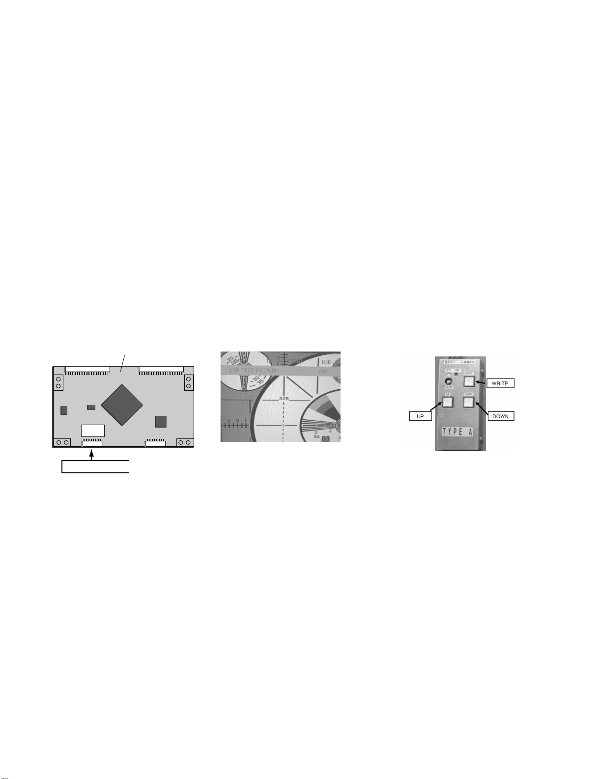
When replacing the LCD control PCB, follow these steps to adjust VCOM.
1) Remove the wire from the LCD control PCB CN3.
2) Connect a wire of the VCOM adjustment jig (electronic volume adjustment BOX) to CN3 (see Fig. 1).
3) Turn on the TV set.
4) Turn on the jig (connect to the AC).
5) Enter the process mode to display the item “LCD TEST PATTERN OFF” (see Fig. 2).
6) Press the volume up key once to display a flicker pattern.
7) Press the jig's UP/DOWN switch while looking at the screen to adjust the point so that the flicker is minimized (see Fig. 3).
8) After completing adjustment, press the WRITE switch and make sure the lamp of the WRITE button goes out. (Writing is complete when the lamp
goes out.)
9) Turn off the jig (turn the AC off).
10)Turn off the TV set.
11)Remove the jig’s wire connected to CN3.
12)Reconnect the wire of the set to CN3.
'ZCORNGQH.%&%QPVTQN29$
CN3
Jig connection
Fig. 1 Jig connecting location
Fig. 2 Test pattern selection screen
Fig. 3 VCOM adjustment jig (RUNTZA059WJZZ)
i
Page 3

PartsGuide
LC-45D40U
PARTS GUIDE
No. S77M9LC45D40U
LCD COLOR TELEVISION
[1] LCD MODULE Assembly
MODEL
CONTENTS
LC-45D40U
Parts marked with " " are important for maintaining the safety of the set. Be sure to replace these
parts with specified ones for maintaining the safety and performance of the set.
This document has been published to be used
for after sales service only.
The contents are subject to change without notice.
Page 4

LC-45D40U
[1] LCD MODULE Assembly
J
2
3
1
I
7
4
H
6
G
5
9
11
7
12
8
10
F
13
14
13
E
15
D
19
18
C
17
B
22
21
23
16
20
A
12345678910
24
2625
2
Page 5

LC-45D40U
NO. PARTS CODE
PRICE
RANK
NEW
MARK
PAR T
DELIVERY
[1] LCD MODULE Assembly
1 R1LK445T3LZ10 GN J LCD Module Ass'y
2 LANGK3580TPZZ AZ N J Vessel (Top)
3 LANGK3580TPZA BC N J Vessel (Bottom)
4 LANGK3579TPZZ AS N J Vessel (L, R), x2
5 LANGK3582TPZZ AZ N J Frame (Top)
6 LANGK3583TPZZ AZ N J Frame (Bottom)
7 LANGK3581TPZZ AU N J Frame (L, R), x2
8 LANGK3402TPZZ AD N J Panel Holder, x2
9 CHLDZA724WJ01 AR N J Sheet Holder Ass'y (Top, Bottom), x2
10 CHLDZA723WJ01 AN N J Sheet Holder Ass'y (L, R), x2
11 PSHEPA332WJZZ AZ N J Diffusion Sheet, x2
12 PCOVUA088WJZZ BE N J Diffusion Panel
13 CHLDZA725WJ01 AR N J Lamp Holder, x2
14 KLMP-A120WJZZ BB N J Lamp Unit, x11
15 CCHSMA298WJ01 BX N J B/L-Chassis
16 RUNTKA231WJZZ BF N J INVERTER Unit-A
17 RUNTKA232WJZZ BD N J INVERTER Unit-B
18 RUNTKA233WJZZ BG N J INVERTER Unit-C
19 RUNTKA234WJZZ BD N J INVERTER Unit-D
20 LANGKA695WJFW AP N J Shield Plate (for Inverter)
21 LANGKA696WJFW AH N J Shield Plate (for Inverter)
22 QCNW-E471WJQZ AP N J Cable (for Inverter)
23 LPLTMA011WJFW AM N J Fixing Plate (for LCD CONTROL Unit)
24 CPWBX3397TPZZ BN N J LCD CONTROL Unit
25 PSLDMA893WJFW AK N J Shield Plate (for LCD CONTROL Unit)
26 QPWBM0287TPZZ AH N J CS-FPC, x2
N RCORFA061WJZZ AG N J Ferrite Core, x2
N LX-BZA051WJF7 AB N J Screw, x4
N XBPS730P06WS0 AA N J Screw, x24
N XBPS730P08WS0 AH N J Screw, x6
N XBPS730P06000 AA N J Screw, x4
N LX-BZ2103TPZZ AB N J Screw, x22
DESCRIPTION
3
Page 6

LC-45D40U
COPYRIGHT © 2007 BY SHARP CORPORATION
COPYRIGHT©XXXX BYSHARP CORPORATION
No Part of this publication may be reproduced,
stored in a retrieval system, or transmitted in
any from or by any means, electronic, mechanical,
No part of this publication may be reproduced,
photocopying , recording, or otherwise, without
stored in a retrieval system, or transmitted in
prior written permission of the publisher.
any form or by any means, electronic, mechanical,
photocopying, recording, or otherwise, without
prior written permission of the publisher.
ALL RIGHTS RESERVED.
ALL RIGHTS RESERVED.
TQ2307-S YK. KG
SHARP CORPORATION
AV Systems Group
CS Promotion Center
Yaita,Tochigi 329-2193, Japan
 Loading...