

Page 1
TopPage
LC-42XL2E/S/RU, LC-46XL2E/S/RU, LC-46X20E/S/RU, LC-52XL2E/S/RU, LC-52X20E/S/RU
xxxxxxxxx
SERVICE MANUAL
No.S87O7LC42XL2E
LCD COLOUR TELEVISION
LC-42XL2E/S/RU
LC-46XL2E/S/RU
LC-46X20E/S/RU
LC-42/46/52XL2E/S/RU LC-46/52X20E/S/RU
MODELS
In the interests of user-safety (Required by safety regulations in some countries) the set should be restored to its original condition and only parts identical to those specified should be used.
LC-52XL2E/S/RU
LC-52X20E/S/RU
CONTENTS
SAFETY PRECAUTION
IMPORTANT SERVICE SAFETY
PRECAUTION...............................................
Precautions for using lead-free solder ..........
CHAPTER 1. OPERATION MANUAL
[1] SPECIFICATIONS
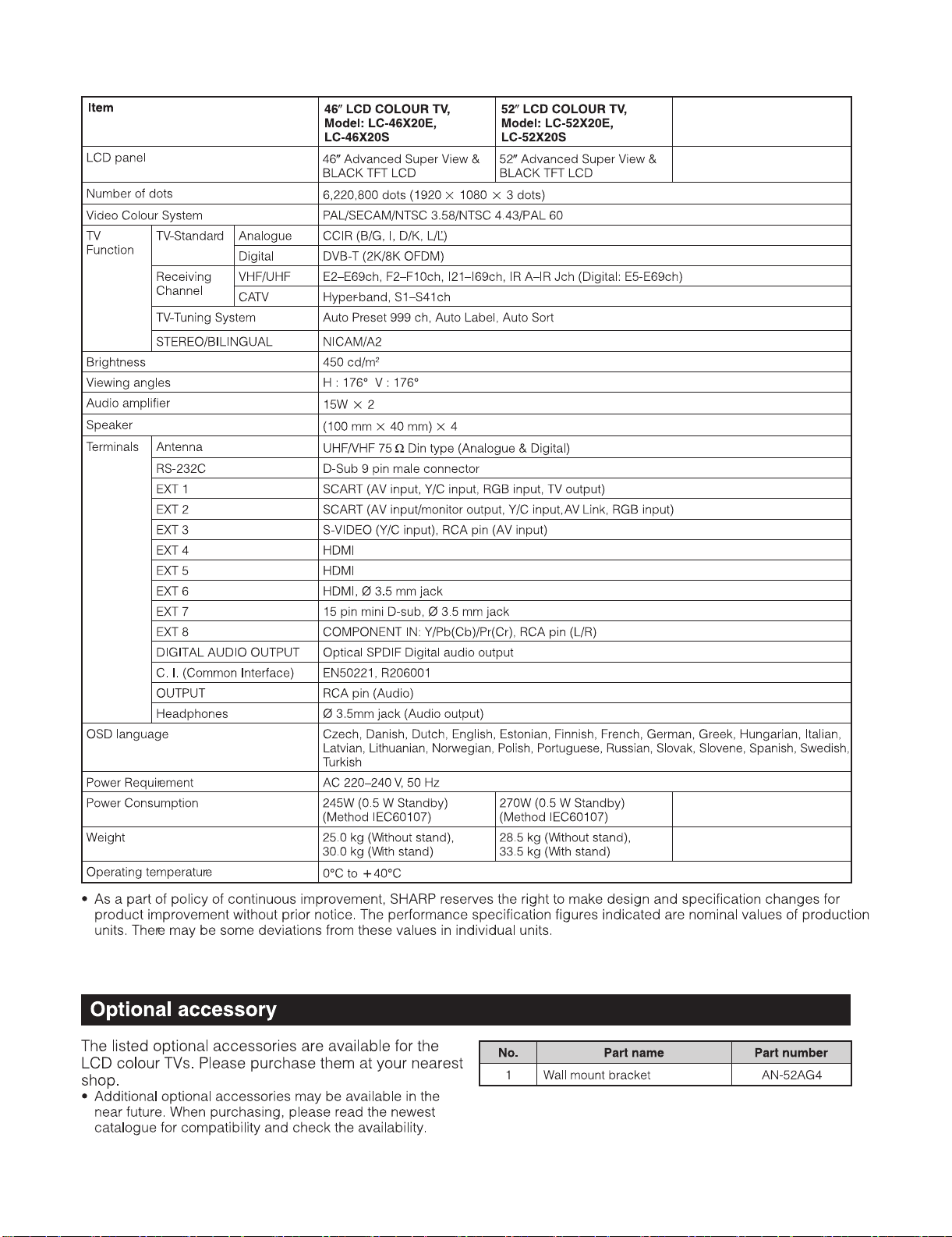
(LC-42/46/52XL2E/S/RU)..............................
[2] SPECIFICATIONS
(LC-46/52X20E/S/RU)...................................
[3] OPERATION MANUAL
(LC-42/46/52XL2E/S/RU)..............................
[4] OPERATION MANUAL
(LC-46/52X20E/S/RU)...................................
[5] DIMENSIONS (LC-42/46/52XL2E/S/RU)......
[6] DIMENSIONS (LC-46/52X20E/S/RU)...........
CHAPTER 2. REMOVING OF MAJOR PARTS
[1] REMOVING OF MAJOR PARTS
(LC-42XL2E/S/RU)........................................
[2] REMOVING OF MAJOR PARTS
(LC-46XL2E/S/RU)........................................
[3] REMOVING OF MAJOR PARTS
(LC-46X20E/S/RU)........................................
[4] REMOVING OF MAJOR PARTS
(LC-52XL2E/S/RU)........................................
[5] REMOVING OF MAJOR PARTS
(LC-52X20E/S/RU)........................................
CHAPTER 3. ADJUSTMENT PROCEDURE
[1] ADJUSTMENT PROCEDURE......................
CHAPTER 4. TROUBLESHOOTING TABLE
[1] TROUBLESHOOTING TABLE......................
.............. i
............. ii
..........1-1
..........1-2
..........1-3
..........1-8
........1-13
........1-14
..........2-1
........2-14
........2-26
........2-38
........2-50
..........3-1
..........4-1
CHAPTER 5. MAJOR IC INFORMATIONS
[1] MAJOR IC INFORMATIONS.........................
CHAPTER 6. BLOCK DIAGRAM/WIRING DIAGRAM
[1] SYSTEM BLOCK DIAGRAM ........................
[2] TERMINAL BLOCK DIAGRAM.....................
[3] MAIN BLOCK DIAGRAM ..............................
[4] POWER BLOCK DIAGRAM..........................
[5] WIRING DIAGRAM (LC-42XL2E/S/RU) .......
[6] WIRING DIAGRAM (LC-46XL2E/S/RU) .......
[7] WIRING DIAGRAM (LC-46X20E/S/RU) .......
[8] WIRING DIAGRAM (LC-52XL2E/S/RU) .......
[9] WIRING DIAGRAM (LC-52X20E/S/RU) .......
CHAPTER 7. PRINTED WIRING BOARD
[1] MAIN UNIT PRINTED WIRING BOARD.......
[2] TERMINAL UNIT PRINTED WIRING BOARD
[3] R/C, LED UNIT PRINTED WIRING BOARD.
[4] KEY UNIT PRINTED WIRING BOARD.........
[5] MINI AV UNIT PRINTED WIRING
BOARD .........................................................
[6] ILLUMINATION UNIT PRINTED WIRING
BOARD .........................................................
[7] POWER UNIT PRINTED WIRING BOARD ..
[8] AC INLET UNIT PRINTED WIRING BOARD
CHAPTER 8. SCHEMATIC DIAGRAM
[1] DESCRIPTION OF SCHEMATIC DIAGRAM
[2] SCHEMATIC DIAGRAM ...............................
Parts Guide
..........5-1
..........6-1
..........6-2
..........6-3
..........6-4
..........6-5
..........6-6
..........6-7
..........6-8
..........6-9
..........7-1
..........7-5
..........7-7
..........7-7
..........7-8
........7-10
........7-11
........7-13
..........8-1
..........8-2
Parts marked with " " are important for maintaining the safety of the set. Be sure to replace these parts with specified ones for maintaining the
safety and performance of the set.
This document has been published to be used for
after sales service only.
The contents are subject to change without notice.
Page 2
LC-42XL2E/S/RU, LC-46XL2E/S/RU, LC-46X20E/S/RU, LC-52XL2E/S/RU, LC-52X20E/S/RU
LC42XL2E
SAFETY PRECAUTION
Service Manual
IMPORTANT SERVICE SAFETY PRECAUTION
Service work should be performed only by qualified service technicians who are thoroughly familiar with all safety checks and the
servicing guidelines which follow:
WARNING
1. For continued safety, no modification of any circuit should be
attempted.
2. Disconnect AC power before servicing.
CAUTION:
FOR CONTINUED PROTECTION AGAINST A
RISK OF FIRE REPLACE ONLY WITH SAME
TYPE FUSE.
• Use an AC voltmeter having with 5000 ohm per volt, or higher, sensitivity or measure the AC voltage drop across the resistor.
• Connect the resistor connection to all exposed metal parts having a
return to the chassis (antenna, metal cabinet, screw heads, knobs
and control shafts, escutcheon, etc.) and measure the AC voltage
drop across the resistor.
All checks must be repeated with the AC cord plug connection
reversed. (If necessary, a nonpolarized adaptor plug must be used
only for the purpose of completing these checks.)
Any reading of 1.05 V peak (this corresponds to 0.7 mA peak AC.)
or more is excessive and indicates a potential shock hazard which
must be corrected before returning the monitor to the owner.
F7000 (6.3A/250V)
BEFORE RETURNING THE RECEIVER
(Fire & Shock Hazard)
Before returning the receiver to the user, perform the following
safety checks:
3. Inspect all lead dress to make certain that leads are not pinched,
and check that hardware is not lodged between the chassis and
other metal parts in the receiver.
4. Inspect all protective devices such as non-metallic control knobs,
insulation materials, cabinet backs, adjustment and compartment
covers or shields, isolation resistor-capacitor networks, mechanical
insulators, etc.
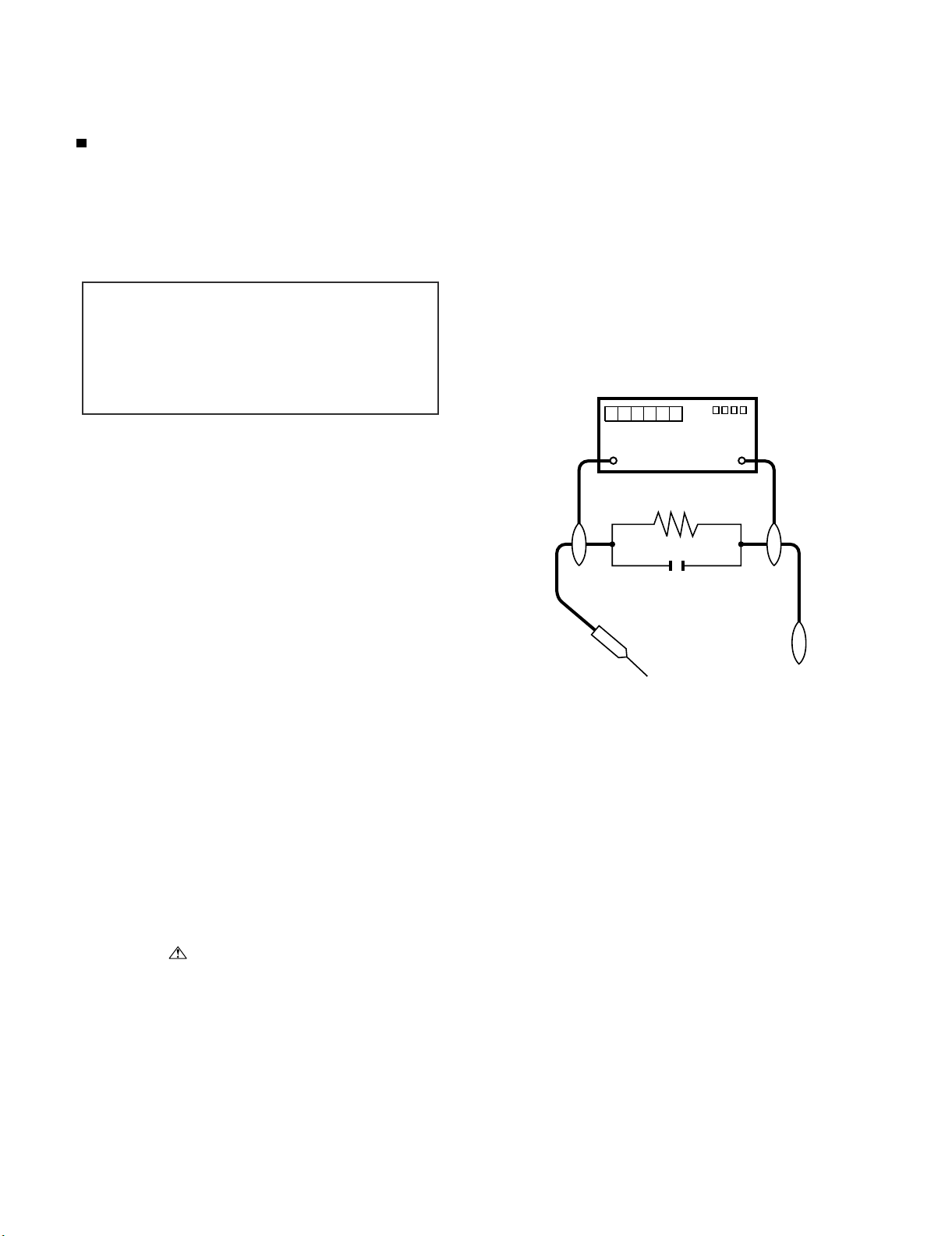
5. To be sure that no shock hazard exists, check for leakage current in
the following manner.
• Plug the AC cord directly into a 220~240 volt AC outlet.
• Using two clip leads, connect a 1.5k ohm, 10 watt resistor paralleled by a 0.15µF capacitor in series with all exposed metal cabinet
parts and a known earth ground, such as electrical conduit or electrical ground connected to an earth ground.
///////////////////////////////////////////////////////////////////////////////////////////////////////////////////////////////////////////////////////////////////////////////////////////////////////////////////////////////////////////
TO EXPOSED
METAL PARTS
SAFETY NOTICE
Many electrical and mechanical parts in LCD color television have
special safety-related characteristics.
These characteristics are often not evident from visual inspection, nor
can protection afforded by them be necessarily increased by using
replacement components rated for higher voltage, wattage, etc.
Replacement parts which have these special safety characteristics are
identified in this manual; electrical components having such features
are identified by “ ” and shaded areas in the Replacement Parts
List and Schematic Diagrams.
///////////////////////////////////////////////////////////////////////////////////////////////////////////////////////////////////////////////////////////////////////////////////////////////////////////////////////////////////////////
For continued protection, replacement parts must be identical to those
used in the original circuit.
The use of a substitute replacement parts which do not have the same
safety characteristics as the factory recommended replacement parts
shown in this service manual, may create shock, fire or other hazards.
DVM
AC SCALE
1.5k ohm
10W
0.15µF
TEST PROBE
CONNECT TO
KNOWN EARTH
GROUND
i
Page 3
LC-42XL2E/S/RU, LC-46XL2E/S/RU, LC-46X20E/S/RU, LC-52XL2E/S/RU, LC-52X20E/S/RU
Precautions for using lead-free solder
Employing lead-free solder
• “PWBs” of this model employs lead-free solder. The LF symbol indicates lead-free solder, and is attached on the PWBs and service manuals. The
alphabetical character following LF shows the type of lead-free solder.
Example:
L Fa
Indicates lead-free solder of tin, silver and copper.
Indicates lead-free solder of tin, silver and copper.
L F a/a
Using lead-free wire solder
• When fixing the PWB soldered with the lead-free solder, apply lead-free wire solder. Repairing with conventional lead wire solder may cause damage or accident due to cracks.
As the melting point of lead-free solder (Sn-Ag-Cu) is higher than the lead wire solder by 40 °C, we recommend you to use a dedicated soldering
bit, if you are not familiar with how to obtain lead-free wire solder or soldering bit, contact our service station or service branch in your area.
Soldering
• As the melting point of lead-free solder (Sn-Ag-Cu) is about 220 °C which is higher than the conventional lead solder by 40 °C, and as it has poor
solder wettability, you may be apt to keep the soldering bit in contact with the PWB for extended period of time. However, Since the land may be
peeled off or the maximum heat-resistance temperature of parts may be exceeded, remove the bit from the PWB as soon as you confirm the
steady soldering condition.
Lead-free solder contains more tin, and the end of the soldering bit may be easily corroded. Make sure to turn on and off the power of the bit as
required.
If a different type of solder stays on the tip of the soldering bit, it is alloyed with lead-free solder. Clean the bit after every use of it.
When the tip of the soldering bit is blackened during use, file it with steel wool or fine sandpaper.
• Be careful when replacing parts with polarity indication on the PWB silk.
Lead-free wire solder for servicing
Part No. Description Code
ZHNDAi123250E J φ0.3mm 250g (1roll) BL
ZHNDAi126500E J φ0.6mm 500g (1roll) BK
ZHNDAi12801KE J φ1.0mm 1kg (1roll) BM
ii
Page 4
LC-42XL2E/S/RU, LC-46XL2E/S/RU, LC-46X20E/S/RU, LC-52XL2E/S/RU, LC-52X20E/S/RU
LC42XL2E
CHAPTER 1. OPERATION MANUAL
Service Manual
[1] SPECIFICATIONS (LC-42/46/52XL2E/S/RU)
1 – 1
Page 5
LC-42XL2E/S/RU, LC-46XL2E/S/RU, LC-46X20E/S/RU, LC-52XL2E/S/RU, LC-52X20E/S/RU
[2] SPECIFICATIONS (LC-46/52X20E/S/RU)
1 – 2
Page 6
LC-42XL2E/S/RU, LC-46XL2E/S/RU, LC-46X20E/S/RU, LC-52XL2E/S/RU, LC-52X20E/S/RU
[3] OPERATION MANUAL (LC-42/46/52XL2E/S/RU)
1 – 3
Page 7
LC-42XL2E/S/RU, LC-46XL2E/S/RU, LC-46X20E/S/RU, LC-52XL2E/S/RU, LC-52X20E/S/RU
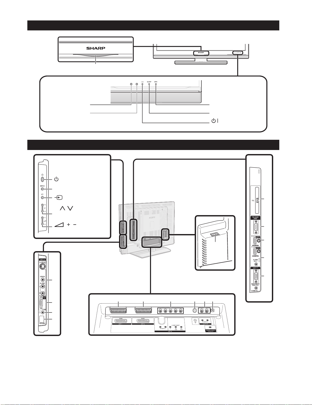
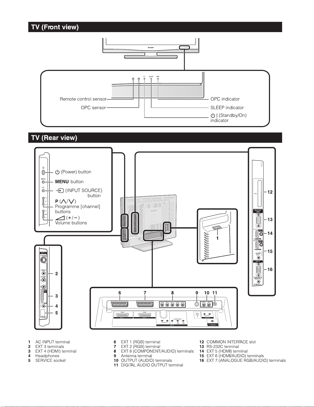
TV (Front view)
Blue illumination LED indicator
Remote control censor
OPC censor
TV (Rear view)
(Power) button
MENU button
(Input source) button
P (
/ )
Programme [channel]
buttons
( / )
Volume buttons
OPC indicator
SLEEP indicator
(Standby/On)
indicator
12
13
14
1
2
3
4
5
1 AC INPUT terminal
2 EXT 3 terminals
3 EXT 4 (HDMI) terminal
4 Headphones
5 SERVICE socket
6 7891011
6 EXT 1 (RGB) terminal
7 EXT 2 (RGB) terminal
8 EXT 8 (COMPONENT/AUDIO) terminals
9 Antenna terminal
10 OUTPUT (AUDIO) terminals
11 DIGITAL AUDIO OUTPUT terminal
12 COMMON INTERFACE slot
13 RS-232C terminal
14 EXT 5 (HDMI) terminal
15 EXT 6 (HDMI/AUDIO) terminals
16 EXT 7 (ANALOGUE RGB/AUDIO) terminals
1 – 4
15
16
* Remove the cover when inserting the CI
Module.
Page 8
LC-42XL2E/S/RU, LC-46XL2E/S/RU, LC-46X20E/S/RU, LC-52XL2E/S/RU, LC-52X20E/S/RU
1 – 5
Page 9
LC-42XL2E/S/RU, LC-46XL2E/S/RU, LC-46X20E/S/RU, LC-52XL2E/S/RU, LC-52X20E/S/RU
1 – 6
Page 10
LC-42XL2E/S/RU, LC-46XL2E/S/RU, LC-46X20E/S/RU, LC-52XL2E/S/RU, LC-52X20E/S/RU
1 – 7
Page 11
LC-42XL2E/S/RU, LC-46XL2E/S/RU, LC-46X20E/S/RU, LC-52XL2E/S/RU, LC-52X20E/S/RU
[4] OPERATION MANUAL (LC-46/52X20E/S/RU)
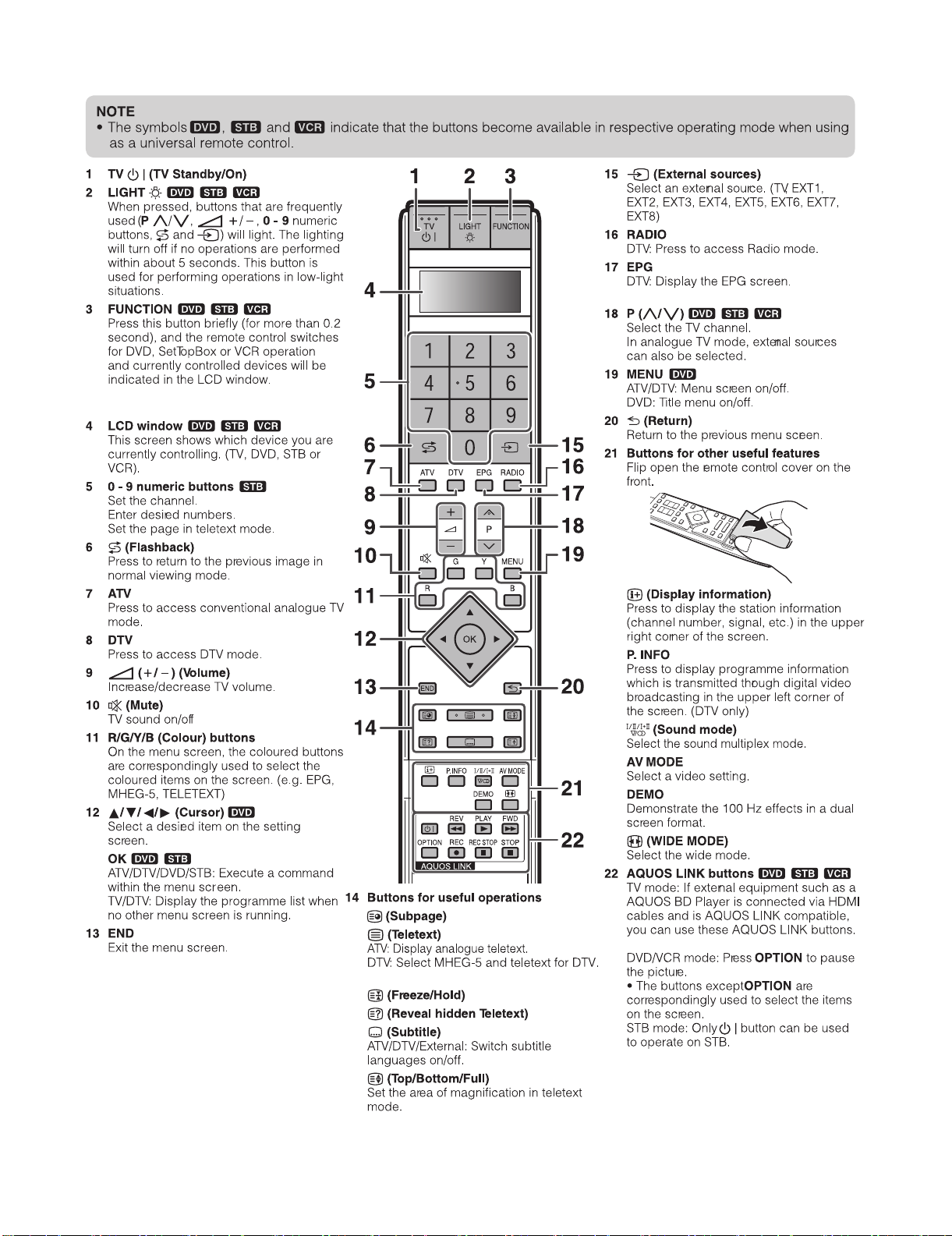
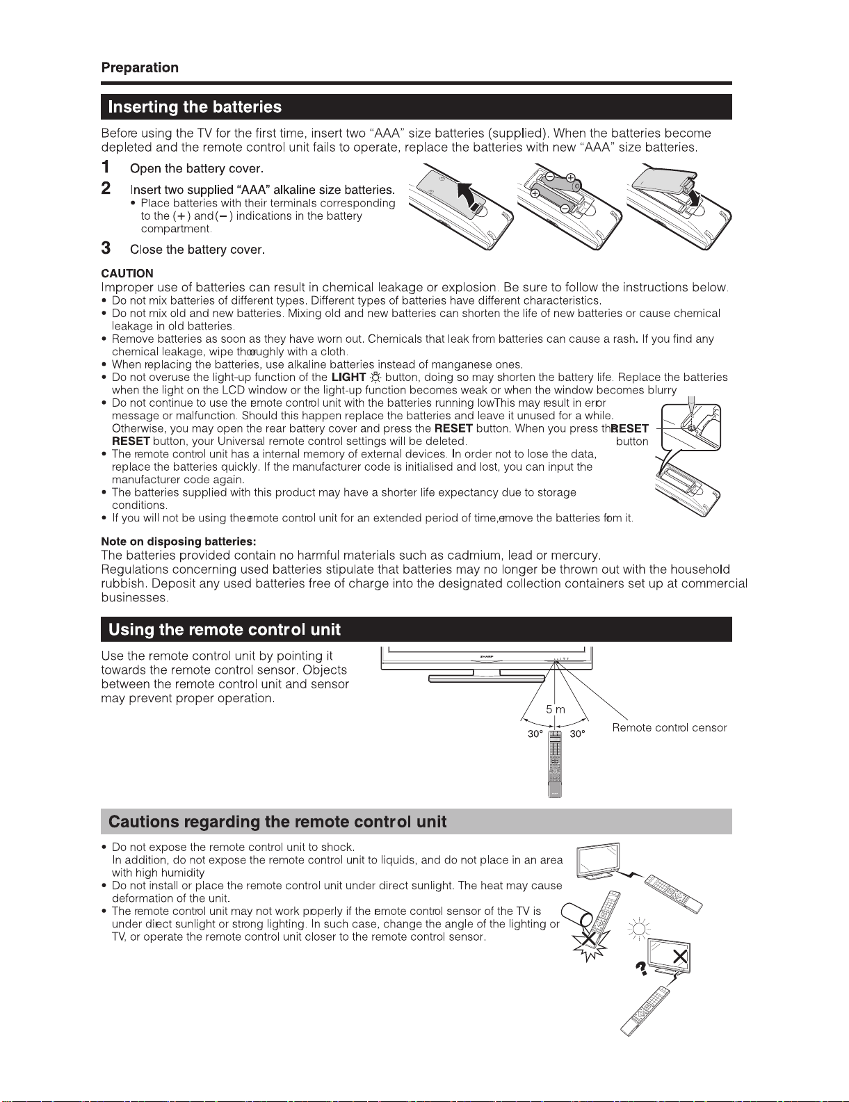
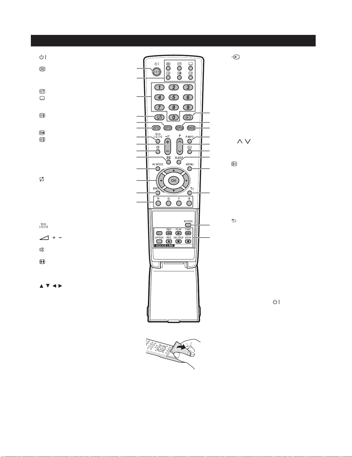
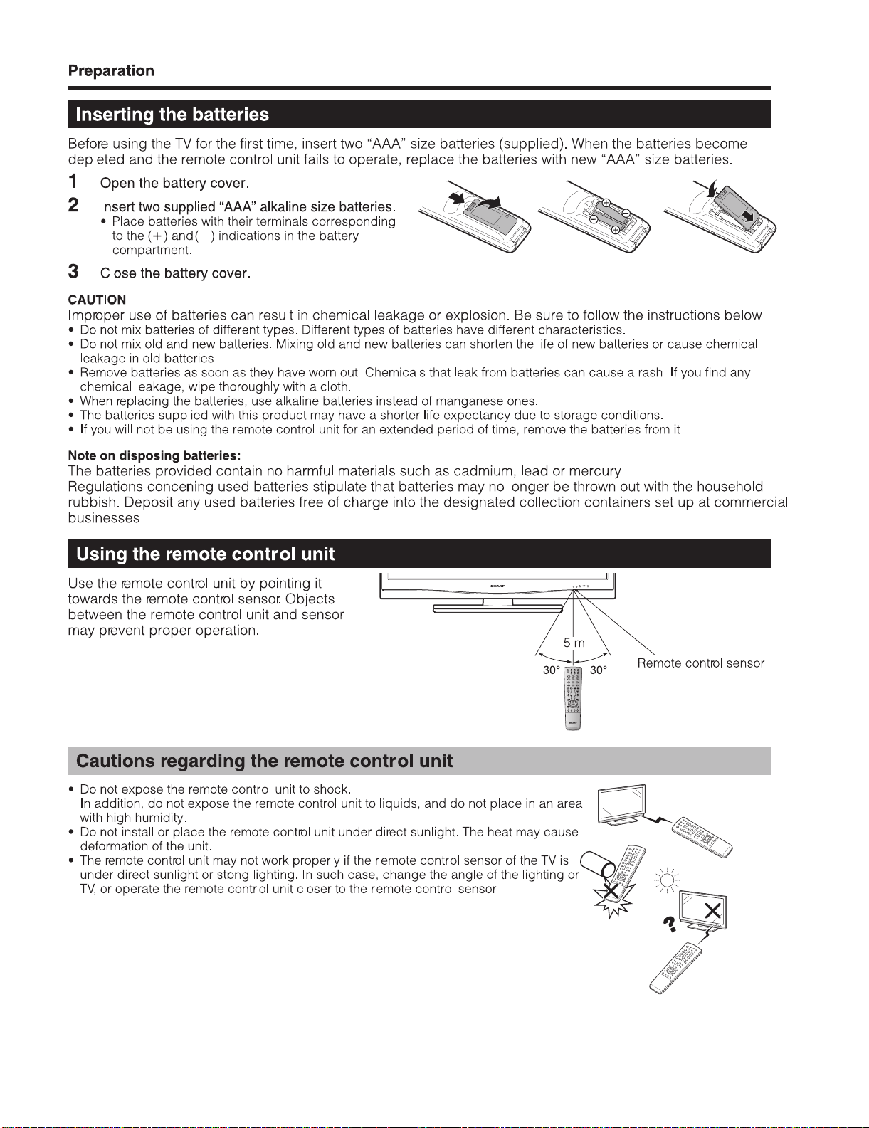
Remote control unit
1 (Standby/On)
2 Buttons for useful operations
(Teletext)
ATV: Display analogue teletext.
DTV: Select MHEG-5 and teletext for DTV.
(Reveal hidden Teletext)
(Subtitle)
ATV/DTV/External: Switch subtitle
languages on/off.
(Top/Bottom/Full)
Set the area of magnification in teletext
mode.
(Subpage)
(Freeze/Hold)
Press to freeze a moving image on the
screen.
3 0 - 9 numeric buttons
Set the channel.
Enter desired numbers.
Set the page in teletext mode.
4
(Flashback)
Press to return to the previous image in
normal viewing mode.
5DTV
Press to access DTV mode.
6ATV
Press to access conventional analogue TV
mode.
7
8 ( / ) (Volume)
9
10
11 AV MODE
12
13 END
14 R/G/Y/B (Colour) buttons
(Sound mode)
Select the sound multiplex mode.
Increase/decrease TV volume.
(Mute)
TV sound on/off
(WIDE MODE)
Select the wide mode.
Select a video setting.
/ / / (Cursor)
Select a desired item on the setting
screen.
OK
ATV/DTV/DVD/STB: Execute a command
within the menu screen.
ATV/DTV: Display the programme list
when no other menu screen is running.
Exit the menu screen.
On the menu screen, the coloured buttons
are correspondingly used to select the
coloured items on the screen. (e.g. EPG,
MHEG-5, TELETEXT)
10
11
12
13
14
15
1
2
3
4
5
6
7
8
9
15
16
17
18
19
20
16 EPG
17 RADIO
18 P. INFO
19 P (
21
20
22
21 SLEEP
23
22 MENU
23
24
24 ACTION (Action Mode)
25
25 AQUOS LINK buttons
(INPUT SOURCE)
Select an input source. (TV, EXT1, EXT2,
EXT3, EXT4, EXT5, EXT6, EXT7, EXT8)
DTV: Display the EPG screen.
DTV: Switch between Radio and Data
mode.
Press to display programme information
which is transmitted through digital video
broadcasting in the upper left corner of
the screen. (DTV only)
/ )
Select the TV channel.
In analogue TV mode, external sources
can also be selected.
(Display information)
Press to display the station information
(channel number, signal, etc.) in the upper
right corner of the screen.
Press to schedule a time for the TV to
automatically standby.
ATV/DTV: Menu screen on/off.
DVD: Title menu on/off.
(Return)
Return to the previous menu screen.
Action Mode on/off.
TV mode: If external equipment such as a
AQUOS BD Player is connected via HDMI
cables and is AQUOS LINK compatible,
you can use these AQUOS LINK buttons.
DVD/VCR mode: Press OPTION to pause
the picture.
• The buttons except OPTION are
correspondingly used to select the items
on the screen.
STB mode: Only the
used to operate on STB.
button can be
1 – 8
Page 12
LC-42XL2E/S/RU, LC-46XL2E/S/RU, LC-46X20E/S/RU, LC-52XL2E/S/RU, LC-52X20E/S/RU
1 – 9
Page 13

LC-42XL2E/S/RU, LC-46XL2E/S/RU, LC-46X20E/S/RU, LC-52XL2E/S/RU, LC-52X20E/S/RU
1 – 10
Page 14
LC-42XL2E/S/RU, LC-46XL2E/S/RU, LC-46X20E/S/RU, LC-52XL2E/S/RU, LC-52X20E/S/RU
1 – 11
Page 15
LC-42XL2E/S/RU, LC-46XL2E/S/RU, LC-46X20E/S/RU, LC-52XL2E/S/RU, LC-52X20E/S/RU
1 – 12
Page 16
LC-42XL2E/S/RU, LC-46XL2E/S/RU, LC-46X20E/S/RU, LC-52XL2E/S/RU, LC-52X20E/S/RU
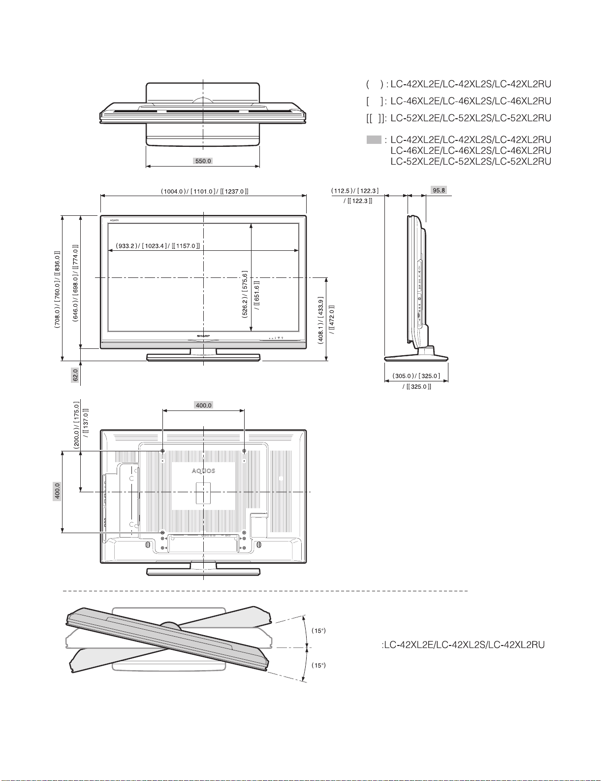
[5] DIMENSIONS (LC-42/46/52XL2E/S/RU)
Unit: mm
1 – 13
Page 17
LC-42XL2E/S/RU, LC-46XL2E/S/RU, LC-46X20E/S/RU, LC-52XL2E/S/RU, LC-52X20E/S/RU
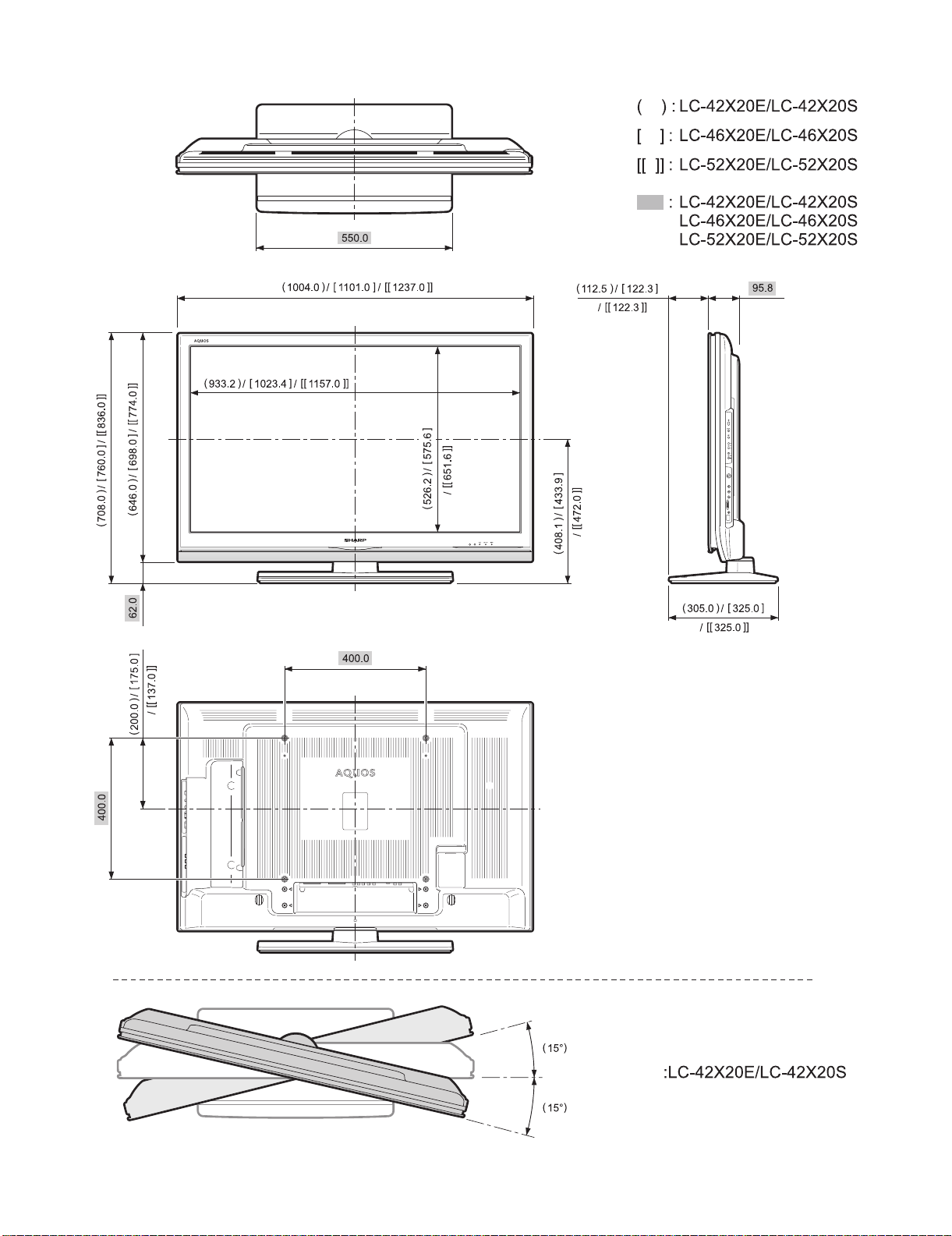
[6] DIMENSIONS (LC-46/52X20E/S/RU)
Unit: mm
1 – 14
Page 18
LC-42XL2E/S/RU, LC-46XL2E/S/RU, LC-46X20E/S/RU, LC-52XL2E/S/RU, LC-52X20E/S/RU
LC42XL2E
CHAPTER 2. REMOVING OF MAJOR PARTS
Service Manual
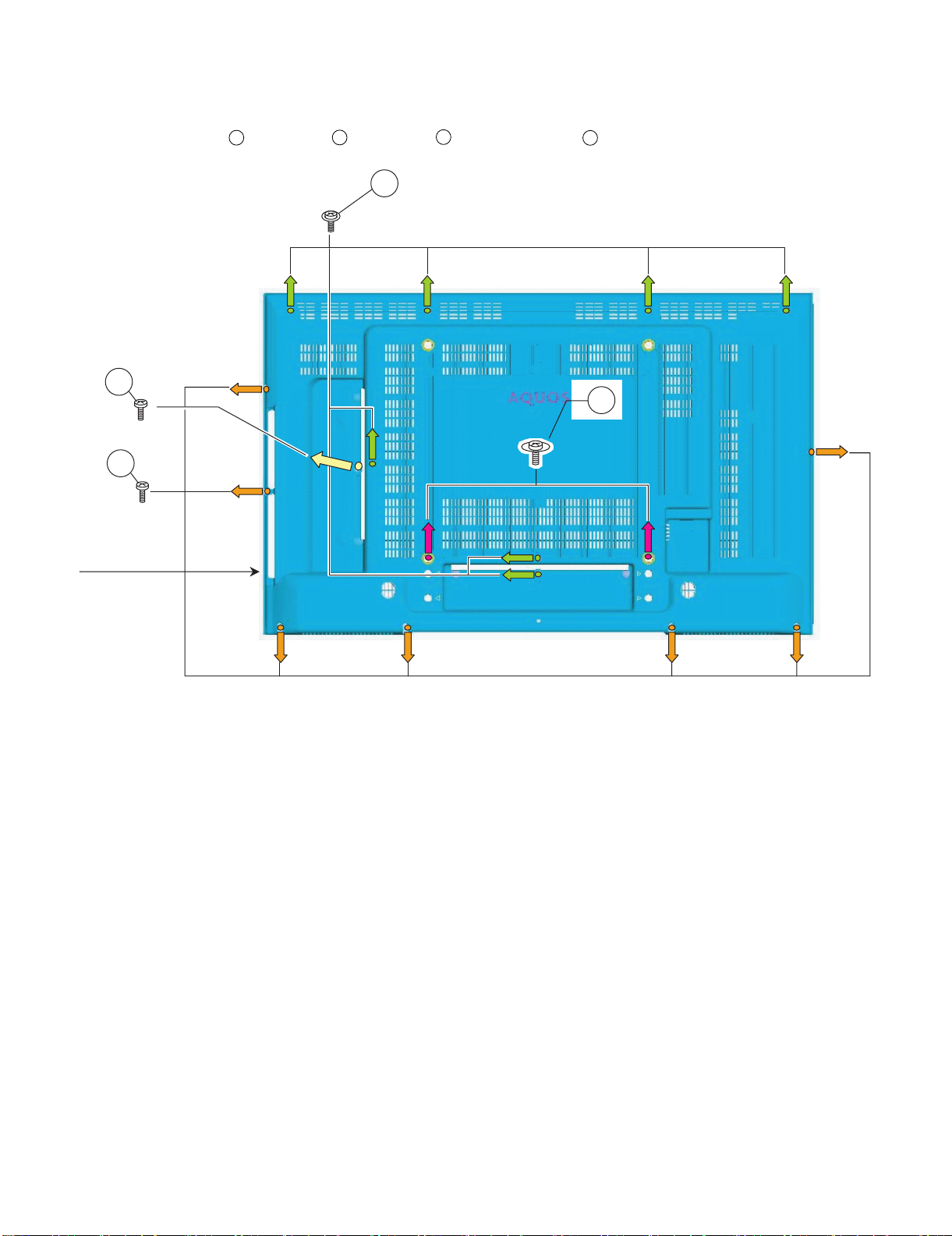
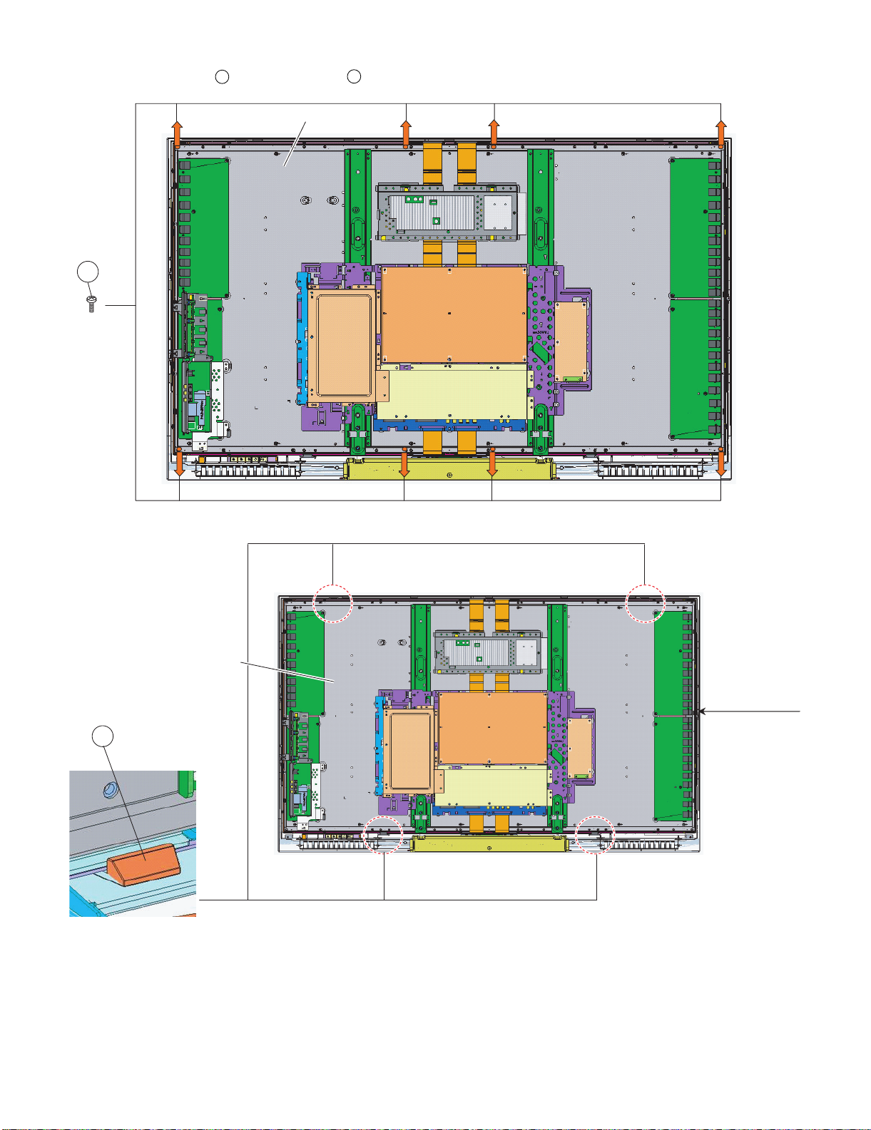
[1] REMOVING OF MAJOR PARTS (LC-42XL2E/S/RU)
1. Remove the 1 lock screw , 2 lock screws , 7 lock screws and the 7 lock screws . Detach the Rear Cabinet.
1
2
3
4
4
1
2
3
REAR CABINET
2 – 1
Page 19
LC-42XL2E/S/RU, LC-46XL2E/S/RU, LC-46X20E/S/RU, LC-52XL2E/S/RU, LC-52X20E/S/RU
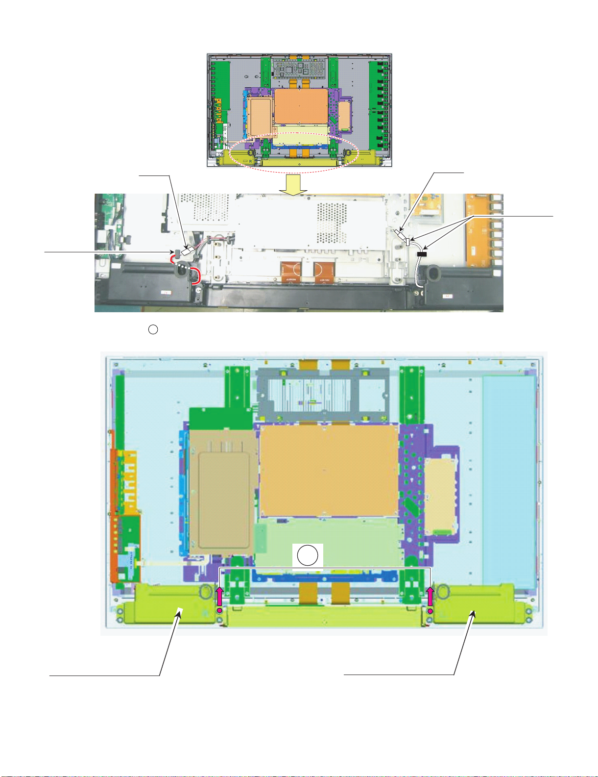
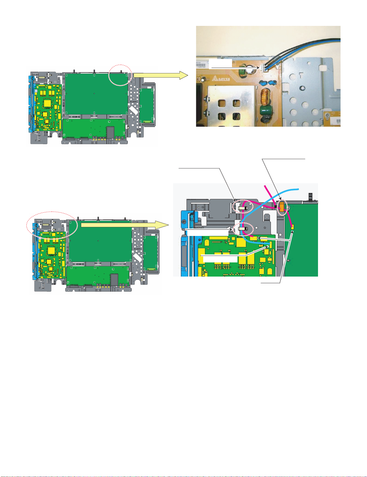
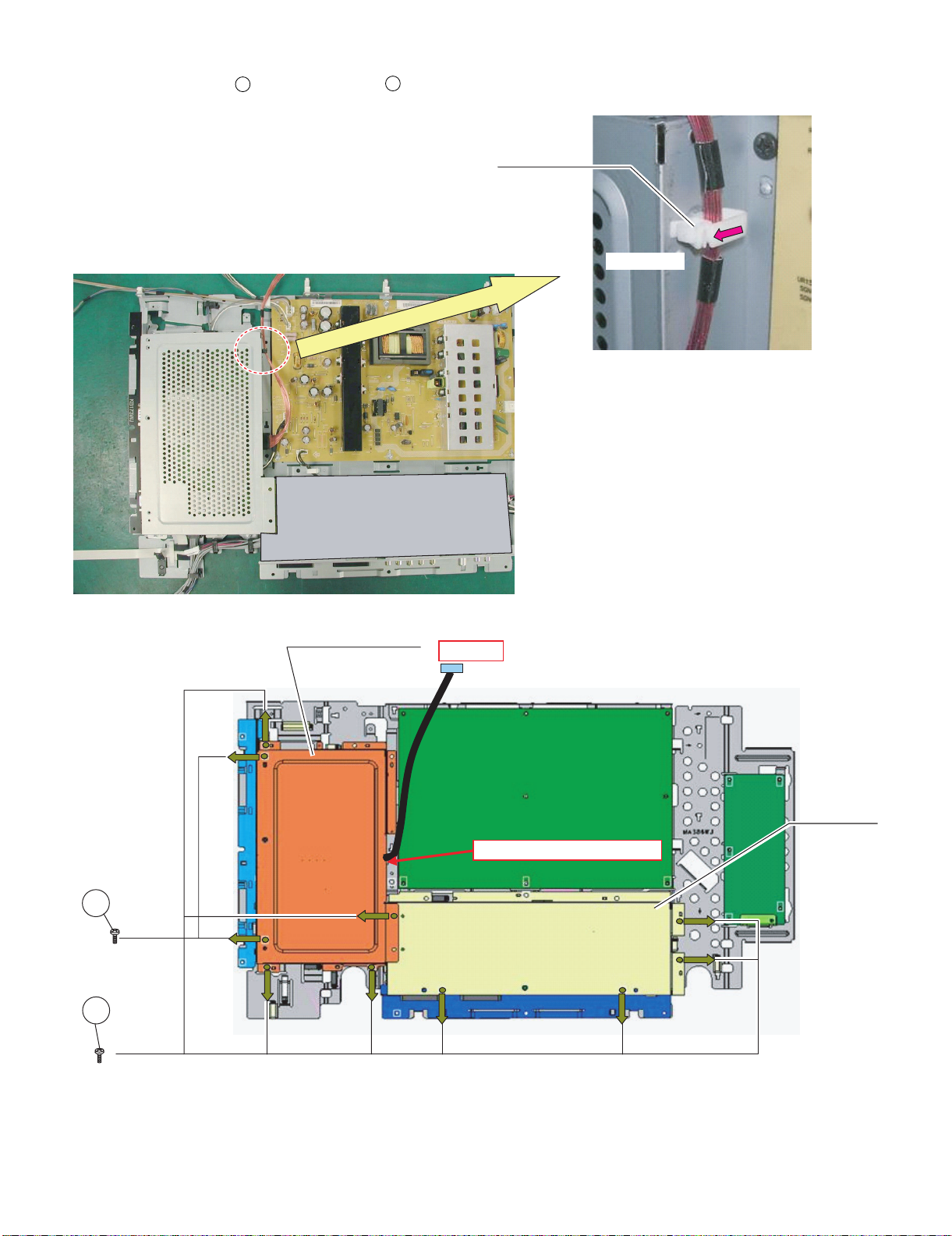
2. Remove all the connectors from PWBs.
Wire "SP"
Wire "SP" to WH
3. Remove the 2 lock screws . and detach the Speaker L/R.
5
Wire "SP"
Wire "SP" to WH
5
Speaker R Speaker L
2 – 2
Page 20
LC-42XL2E/S/RU, LC-46XL2E/S/RU, LC-46X20E/S/RU, LC-52XL2E/S/RU, LC-52X20E/S/RU
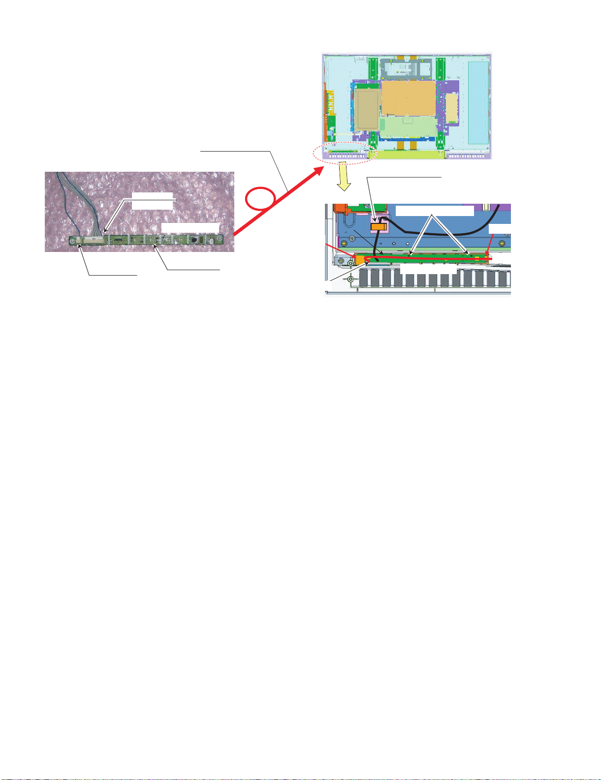
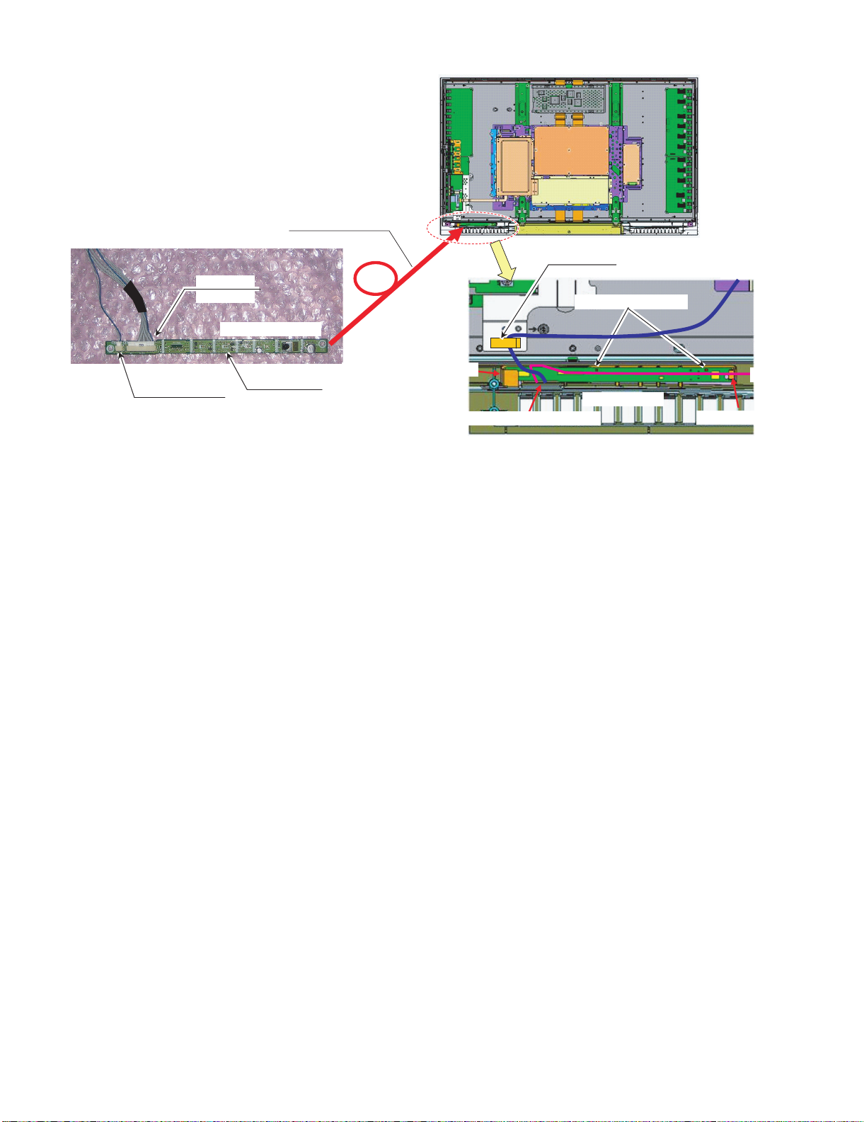
Wire "RA"
from OBON
Wire "RA"
LED PWB Front side
LED PWB Back side
Pull out Wire "IL","RA" from bottom
1st, Set LED PWB Under LIB
#Set PWB to gide lib surely
Next,Push PWB hooked
Wire "IL"
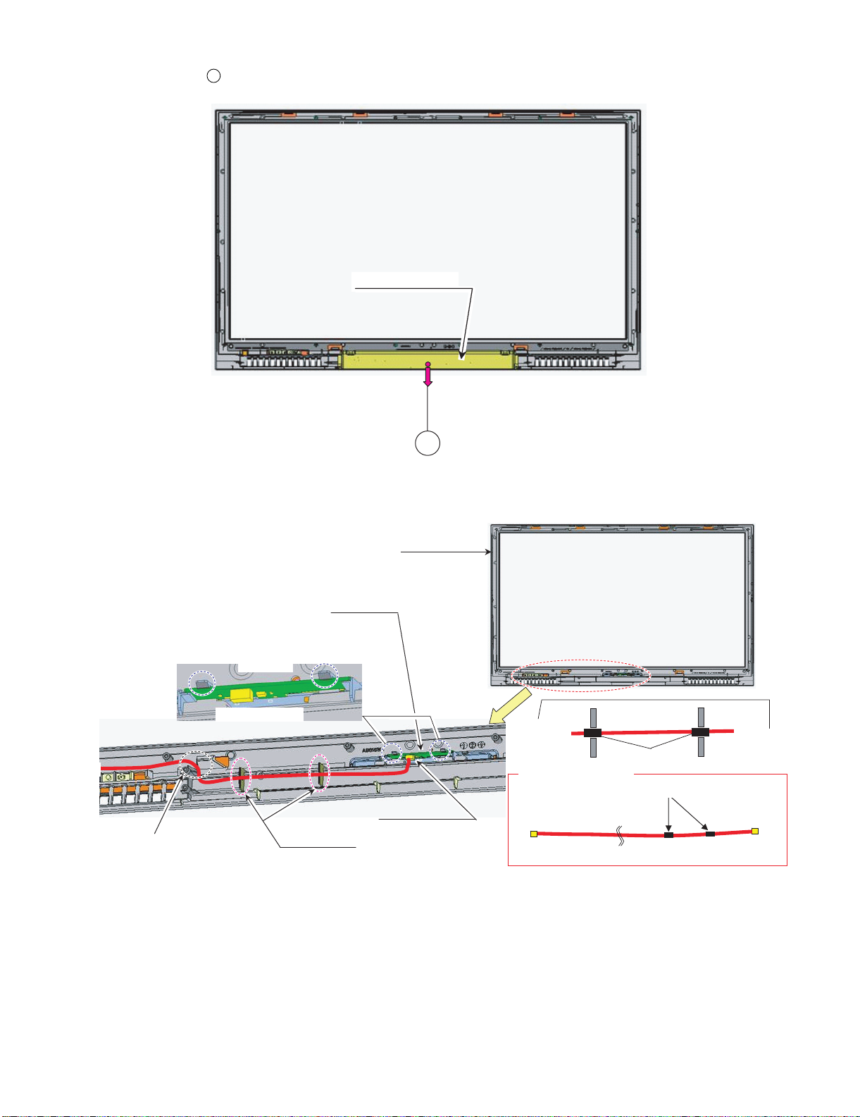
4. Remove all the connectors from PWBs.
LED PWB
(with wire)
Wire "RA" to WH
Wire "IL"
from Illumination
5. Remove the R/C, LED Unit.
LED PWB
2 – 3
Page 21
LC-42XL2E/S/RU, LC-46XL2E/S/RU, LC-46X20E/S/RU, LC-52XL2E/S/RU, LC-52X20E/S/RU
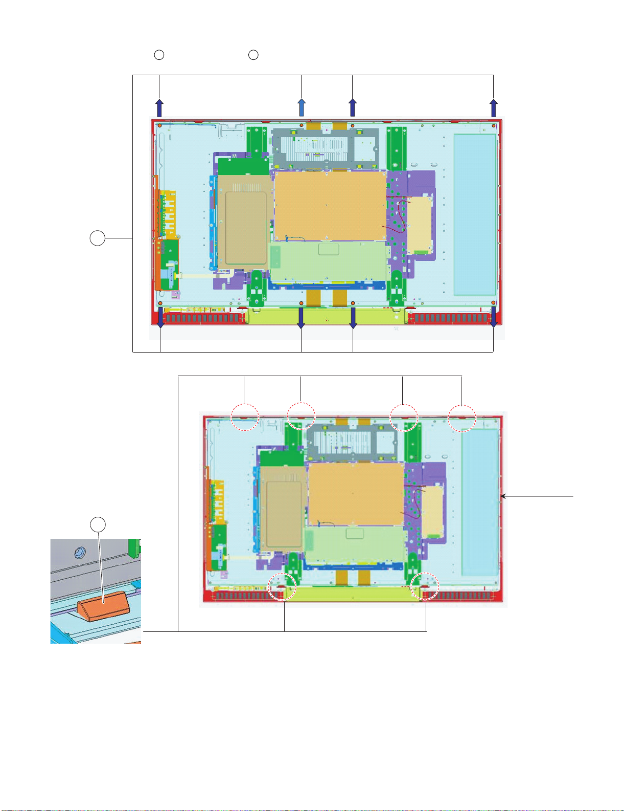
6. Remove the 8 lock screws , and the 6 lock hooks . Detach the LCD Panel Module.
6 7
6
FRONT CABINET
7
2 – 4
Page 22
LC-42XL2E/S/RU, LC-46XL2E/S/RU, LC-46X20E/S/RU, LC-52XL2E/S/RU, LC-52X20E/S/RU
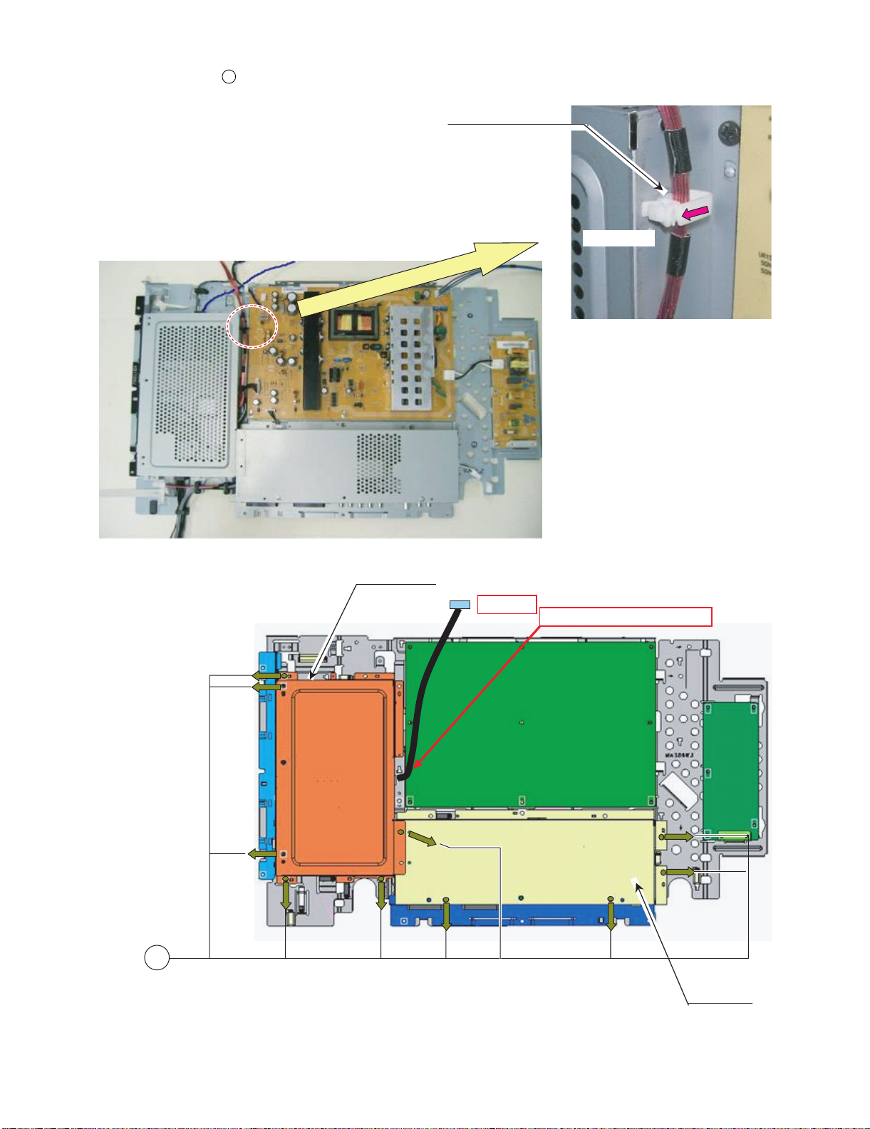
BOTTOM COVER
Wire "IL"
#Hook Surely
#Connector side Down
#Wire "IL" pass between SP Boss
and Panel hooker
Illumination Unit
To LED PWB
TAPING
Wire "IL" Connection Direction
Wire "IL"
Tape
Lib
Lib
7. Remove the 1 lock screw . and detach the Bottom Cover.
8
8. Remove all the connectors from PWBs.
9. Remove the Illumination Unit.
8
Wire "IL" to rib
FRONT CABINET
Illumination Unit
Wire "IL"
2 – 5
Page 23
LC-42XL2E/S/RU, LC-46XL2E/S/RU, LC-46X20E/S/RU, LC-52XL2E/S/RU, LC-52X20E/S/RU
㪮㫀㫉㪼㩷㪣㪙
Wire "LB" to Hole
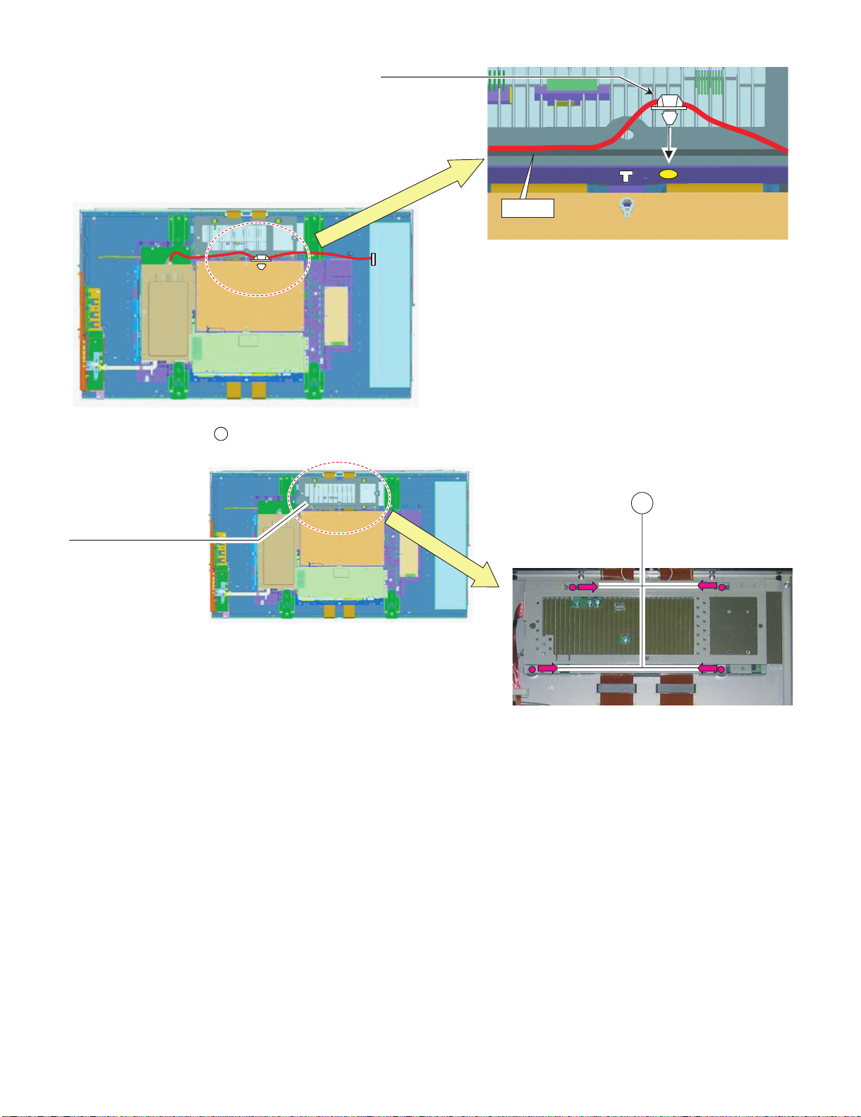
10.Remove the 4 lock screws . and detach the CTL SHIELD with RADIATOR.
CTL-SHIELD with RADIATOR
9
9
2 – 6
Page 24
LC-42XL2E/S/RU, LC-46XL2E/S/RU, LC-46X20E/S/RU, LC-52XL2E/S/RU, LC-52X20E/S/RU
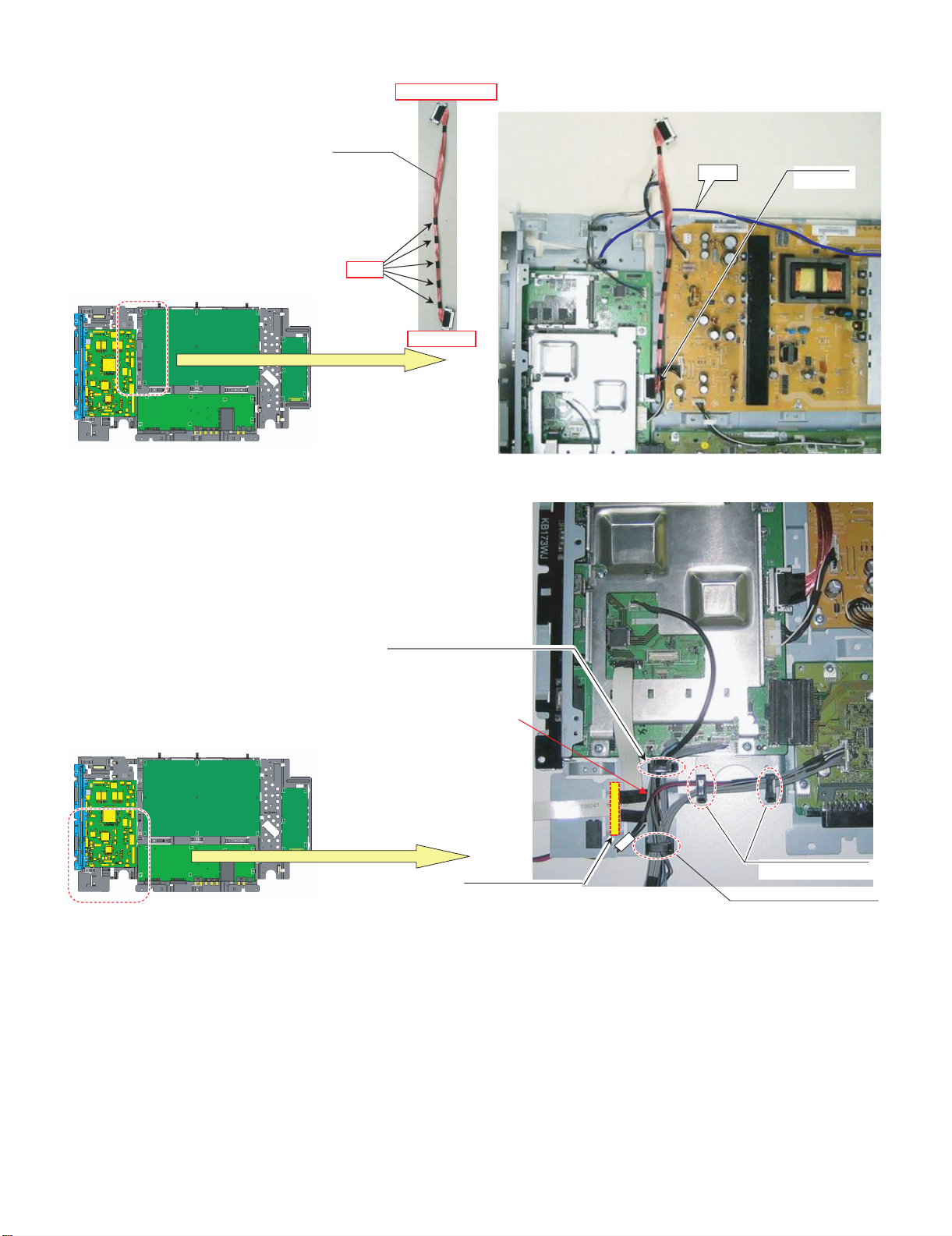
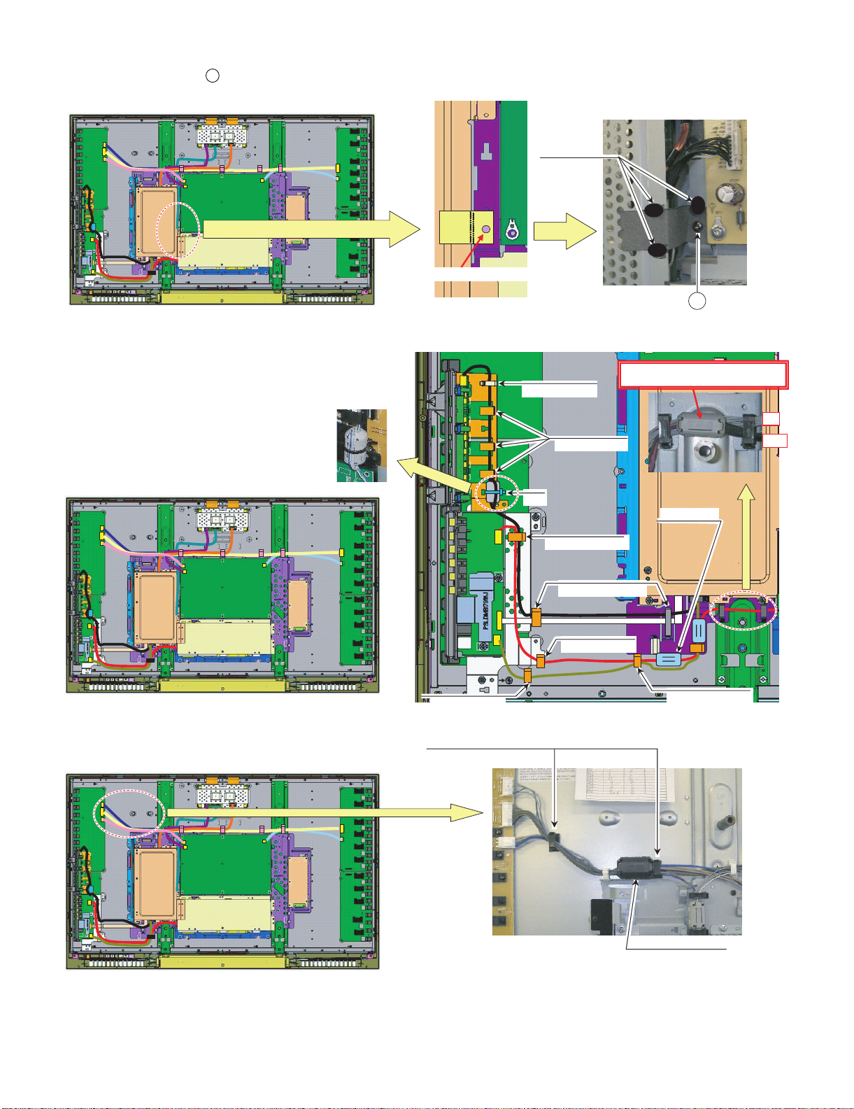
FFC "HM" to WH
Wire "RA"
11.Remove all the connectors from PWBs.
Wire "LB", "LA1" to WH
Wire "KM" to WH
Wire "KM", "VD", "US" to WH
Wire "KM", "VD"to WH
Wire "KM" to Hook
Wire "KM"
Wire "LW"
Wire "FR"
Wire "LA1"
Wire "LB"
Wire "VD"
FFC "HM"
Wire "US"
2 – 7
Page 25
LC-42XL2E/S/RU, LC-46XL2E/S/RU, LC-46X20E/S/RU, LC-52XL2E/S/RU, LC-52X20E/S/RU
PNL SUPPORT ANG
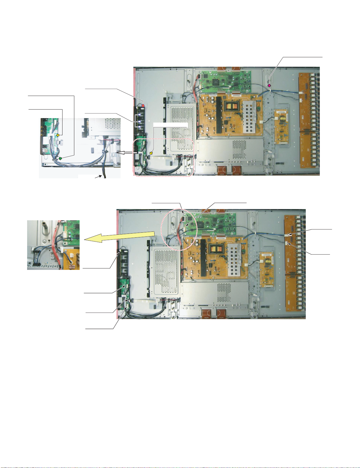
12.Remove the 1 lock screw , and the 11 lock screws . Detach the Chassis Tray and MINI AV Sub Ass’y.
10
11
11
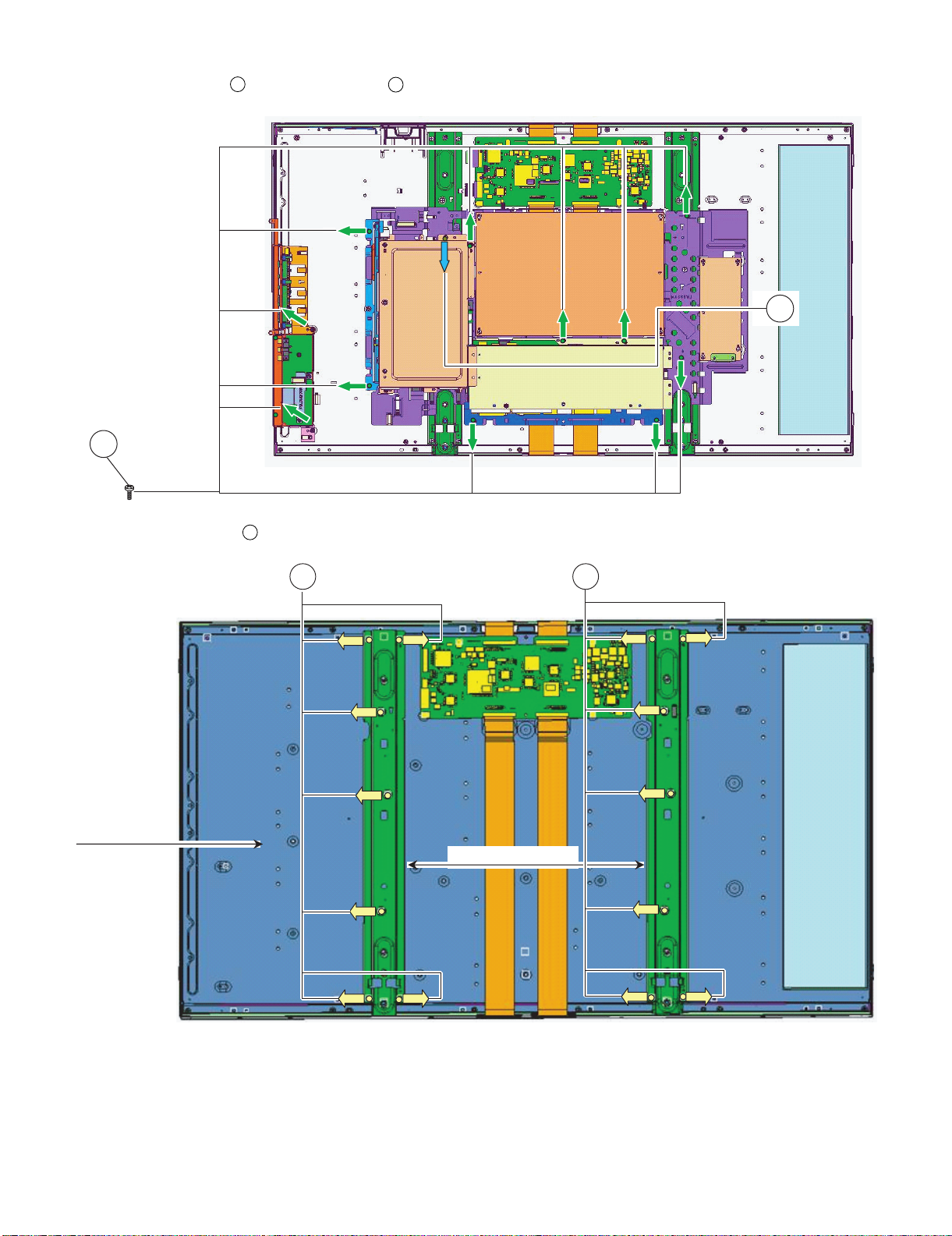
13.Remove the 14 lock screws . and detach the Panel Support Angle.
12
10
LCD MODULE
1212
2 – 8
Page 26
LC-42XL2E/S/RU, LC-46XL2E/S/RU, LC-46X20E/S/RU, LC-52XL2E/S/RU, LC-52X20E/S/RU
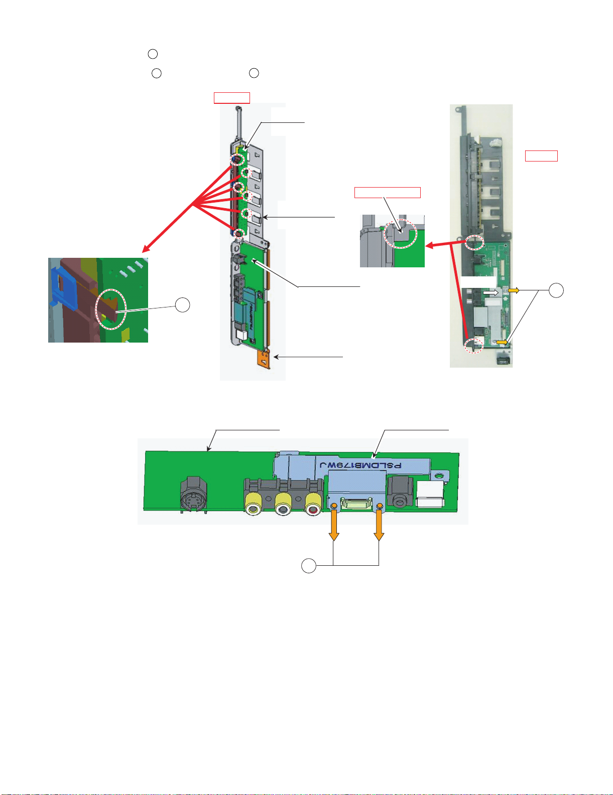
M-AV KEY COV
KEY PWB
Slant View
Top View
#Set PWB under LIB
Open side
14.Remove the 6 lock hooks . and detach the KEY Unit.
15.Remove the 2 lock screws , and the 2 lock screws . Detach the MINI AV Unit.
13
14
15
MINI AV PWB
13
14
MINI AV PWB
MINI AV ANG
MINI-AV SHIELD
15
2 – 9
Page 27
LC-42XL2E/S/RU, LC-46XL2E/S/RU, LC-46X20E/S/RU, LC-52XL2E/S/RU, LC-52X20E/S/RU
Open Side
Pull out Wire "LW" form Opening
Wire "LW"
16.Remove all the connectors from PWBs.
17.Remove the 10 lock screws . and detach the Main Shield and AV Shield.
16
Wire "LW" to WH
16
MAIN SHIELD
AV SHIELD
2 – 10
Page 28
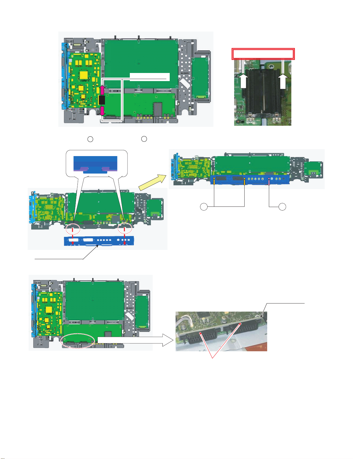
LC-42XL2E/S/RU, LC-46XL2E/S/RU, LC-46X20E/S/RU, LC-52XL2E/S/RU, LC-52X20E/S/RU
B to B connection
Pull same time
#SCART Angle Stepping on terminal
18.Remove all the connectors from PWBs.
19.Remove the 2 lock screws , and the 1 lock screw . Detach the Terminal Angle Bottom.
17
18
18 17
TML ANG BTM
SCART ANGLE
2 – 11
Page 29
LC-42XL2E/S/RU, LC-46XL2E/S/RU, LC-46X20E/S/RU, LC-52XL2E/S/RU, LC-52X20E/S/RU
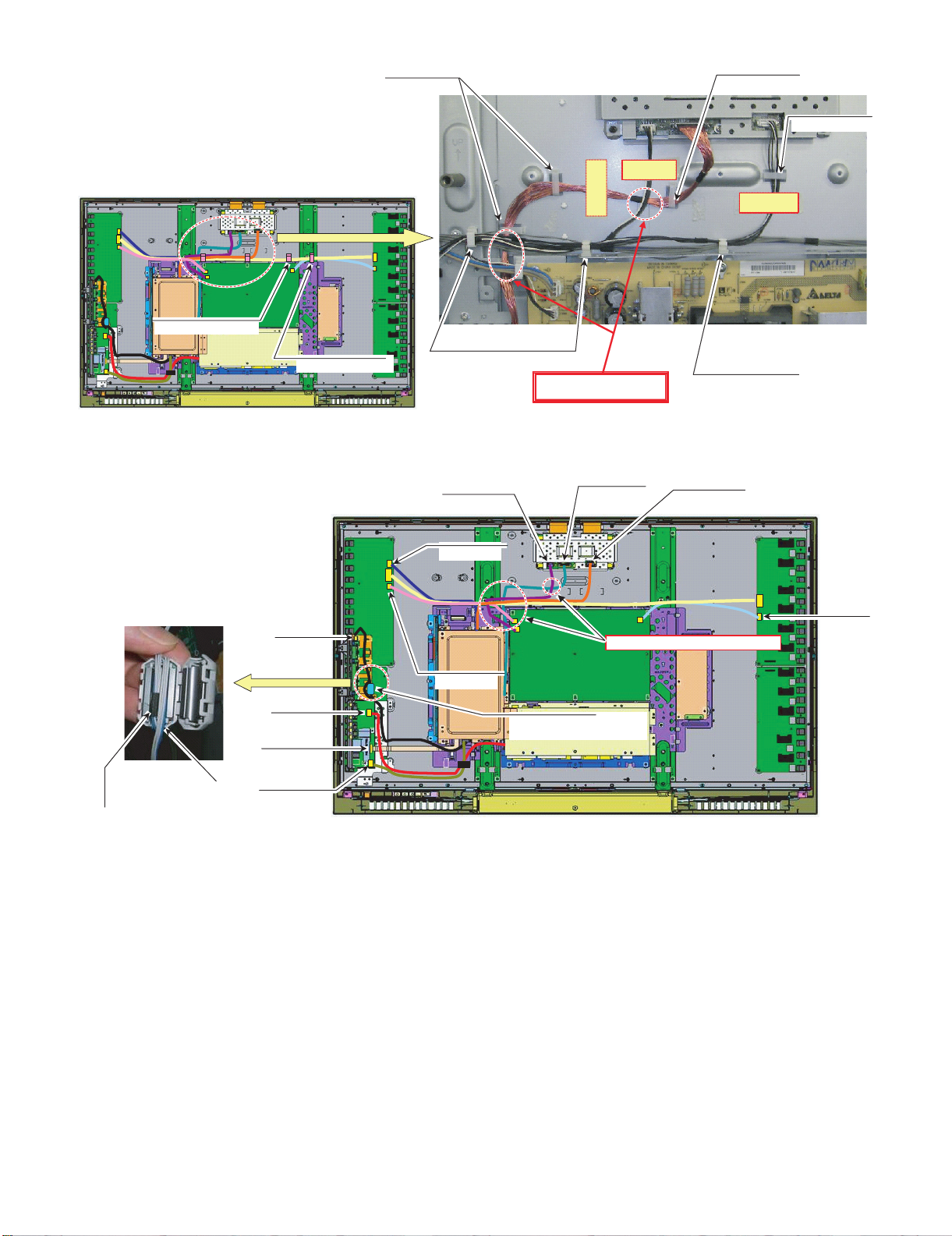
Wire "LW"
wire LB
To Main PWB
To LCD Control PWB
Taping
Wire "VD","SP_R" to WH
Wire "HM" to WH
20.Remove all the connectors from PWBs.
Wire "LW"
Wire "RA","US","KM" to WH
Upper side wire SP_R
Wire "RA","US","KM","VD" to WH
2 – 12
Page 30
LC-42XL2E/S/RU, LC-46XL2E/S/RU, LC-46X20E/S/RU, LC-52XL2E/S/RU, LC-52X20E/S/RU
Wire "LA1"
Wire "LB","PL" to WH
Wire "LB"
Wire "PL" to WH
Wire "PL" to WH
Wire "LB" to this WH
Wire ”PL”
2 – 13
Page 31

LC-42XL2E/S/RU, LC-46XL2E/S/RU, LC-46X20E/S/RU, LC-52XL2E/S/RU, LC-52X20E/S/RU
[2] REMOVING OF MAJOR PARTS (LC-46XL2E/S/RU)
1. Remove the 2 lock screws , 6 lock screws and the 8 lock screws . Detach the Rear Cabinet.
1
2
3
3
REAR CABNET
2 1
2 – 14
Page 32

LC-42XL2E/S/RU, LC-46XL2E/S/RU, LC-46X20E/S/RU, LC-52XL2E/S/RU, LC-52X20E/S/RU
2. Remove all the connectors from PWBs.
Wire "SP"
Wire "SP" to WH
Wire "SP" to PIN
3. Remove the 2 lock screws . and detach the Speaker L/R.
4
Wire "SP"
Wire "SP" to WH
4
Speaker R Speaker L
2 – 15
Page 33
LC-42XL2E/S/RU, LC-46XL2E/S/RU, LC-46X20E/S/RU, LC-52XL2E/S/RU, LC-52X20E/S/RU
Wire "RA"
from OBON
Wire "IL"
Wire
R/C, LED PWB Front side
LED PWB Back side
(3-3)Pull out Wire "IL","RA" from bottom
(3-1) Set R/C, LED PWB Under LIB
(3-2) Push PWB hooked
#Set PWB to gide lib surely
4. Remove all the connectors from PWBs.
R/C, LED PWB
(with wire)
Wire "RA" to WH
Wire "IL"
from Illumination
5. Remove the R/C, LED Unit.
R/C, LED PWB
2 – 16
Page 34

LC-42XL2E/S/RU, LC-46XL2E/S/RU, LC-46X20E/S/RU, LC-52XL2E/S/RU, LC-52X20E/S/RU
6. Remove the 8 lock screws , and the 6 lock hooks . Detach the LCD Panel Module.
LCD PANEL MODULE
5
6
5
LCD PANEL MODULE
6
FRONT CABINET
2 – 17
Page 35

LC-42XL2E/S/RU, LC-46XL2E/S/RU, LC-46X20E/S/RU, LC-52XL2E/S/RU, LC-52X20E/S/RU
BOTTOM COVER
FRONT CABINET
Wire "IL"
#Hook Surely
#Connector side Down
#Wire "IL" pass between SP Boss
and Panel hooker
Wire "IL" Connection Direction
7. Remove the 2 lock screws . and detach the Bottom Cover.
7
8. Remove all the connectors from PWBs.
7
Illumination Unit
Wire "IL" to rib
FRONT CABINET
Wire "IL"
To Illumination UnitTo R/C, LED PWB
2 – 18
Page 36

LC-42XL2E/S/RU, LC-46XL2E/S/RU, LC-46X20E/S/RU, LC-52XL2E/S/RU, LC-52X20E/S/RU
FFC "HM" to WH
Wire "KM" to Hook
Wire "LC", "LA1" to WH
9. Remove the Illumination Unit.
10.Remove the 4 lock screws . and detach the CTL SHIELD with RADIATOR.
CTL-SHIELD with RADIATOR
8
11.Remove all the connectors from PWBs.
Wire "LC", "LA2", "LB" to WH
Wire "LW", "PL" to WH
8
Wire "LC" to WH
Wire "KM" to WH
Wire "LB"
Wire "LA2"
Wire "KM"
Wire "KM", "VD", "US" to WH
Wire "LW"
Wire "LP"
Wire "LA1"
Wire "VD"
FFC "HM"
Wire "US"
2 – 19
Page 37

LC-42XL2E/S/RU, LC-46XL2E/S/RU, LC-46X20E/S/RU, LC-52XL2E/S/RU, LC-52X20E/S/RU
Wire "LC "
PNL SUPPORT ANG
Wire "LC"
12.Remove the 1 lock screw , and the 12 lock screws . Detach the Chassis Tray and MINI AV Sub Ass’y.
MINI AV SUB ASSY
9
CHASSIS TRAY
10
9
10
13.Remove the 14 lock screws . and detach the Panel Support Angle.
LCD MODULE
11
11
2 – 20
Page 38

LC-42XL2E/S/RU, LC-46XL2E/S/RU, LC-46X20E/S/RU, LC-52XL2E/S/RU, LC-52X20E/S/RU
M-AV KEY COV
Slant View
Top View
#Set PWB under LIB
14.Remove the 6 lock hooks . and detach the KEY Unit.
15.Remove the 2 lock screws , and the 2 lock screws . Detach the MINI AV Unit.
12
13 14
KEY PWB
MINI AV PWB
12
MINI AV ANG
13
MINI AV PWB
MINI-AV SHIELD
14
2 – 21
Page 39

LC-42XL2E/S/RU, LC-46XL2E/S/RU, LC-46X20E/S/RU, LC-52XL2E/S/RU, LC-52X20E/S/RU
Open Side
Wire "LW"
Pull out Wire "LW" form Opening
16.Remove all the connectors from PWBs.
17.Remove the 10 lock screws . and detach the Main Shield and AV Shield.
15
Wire "LW" to WH
15
MAIN SHIELD
AV SHIELD
2 – 22
Page 40

LC-42XL2E/S/RU, LC-46XL2E/S/RU, LC-46X20E/S/RU, LC-52XL2E/S/RU, LC-52X20E/S/RU
B to B connection
Pull same time
#SCART Angle Stepping on terminal
18.Remove all the connectors from PWBs.
19.Remove the 2 lock screws , and the 1 lock screw . Detach the Terminal Angle Bottom.
TML ANG BTM
16 17
1716
SCART ANGLE
2 – 23
Page 41

LC-42XL2E/S/RU, LC-46XL2E/S/RU, LC-46X20E/S/RU, LC-52XL2E/S/RU, LC-52X20E/S/RU
Wire "VD" to WH
Wire "KM"
#Shape Wire "US"
like this
Wire "RA","US","KM" to WH
Wire "VD"
Wire "RA"
#Don't make mistake Wire "VD" and "RA"
Wire "LW"
Wire "HM"
Wire
Wire "US"
Wire
Wire "VD"
Wire
Wire "RA"
Wire "LW"
To Main PWB
To LED PWB
To Main PWB
To LCD Control PWB
Wire "LA1"
Wire "LA1"
#No shape Wire "LA1" to WH
20.Remove all the connectors from PWBs.
Wire "US"
Wire "LW"
Wire "HM"
Wire "HM" to WH
Wire "RA","US","KM","VD" to WH
2 – 24
Page 42

LC-42XL2E/S/RU, LC-46XL2E/S/RU, LC-46X20E/S/RU, LC-52XL2E/S/RU, LC-52X20E/S/RU
Wire "LB"
Wire "LB","PL" to WH
Wire "PL"
Wire "LA2"
Wire "LB"
Wire "PL"
Wire "LA2","PL" to WH
Wire "LA2","LB" to WH
Wire "LA2"
2 – 25
Page 43

LC-42XL2E/S/RU, LC-46XL2E/S/RU, LC-46X20E/S/RU, LC-52XL2E/S/RU, LC-52X20E/S/RU
[3] REMOVING OF MAJOR PARTS (LC-46X20E/S/RU)
1. Remove the 1 lock screw , 2 lock screws , 6 lock screws and the 7 lock screws . Detach the Rear Cabinet.
1
2
3
4
4 1
REAR CABINET
23
2 – 26
Page 44

LC-42XL2E/S/RU, LC-46XL2E/S/RU, LC-46X20E/S/RU, LC-52XL2E/S/RU, LC-52X20E/S/RU
Wire "SP" to WH
Wire "SP"
2. Remove all the connectors from PWBs.
Wire "SP" to WH
Wire "SP" to PIN
Wire "SP"
3. Remove the 2 lock screws . and detach the Speaker L/R.
5
5
Speaker R Speaker L
2 – 27
Page 45
LC-42XL2E/S/RU, LC-46XL2E/S/RU, LC-46X20E/S/RU, LC-52XL2E/S/RU, LC-52X20E/S/RU
#Fit CONDUCTIVE Tape hole to SCREW hole
#For EMC
Set Wire "VD" under Wire "SP-R" (with core)
VD
SP-R
for Wire "VD"
Wire "HM","KM" to WH
Wire "US","VD" to WH
Wire "US" to WH
Wire "VD" to WH
Wire "VD","KM to WH
Wire "KM to WH
Wire "KM" to Hook
WH
4. Remove the 1 lock screw .
6
5. Remove all the connectors from PWBs.
SILICON BOND
6
Wire "LA2","LB","LC" to WH
for Wire "LA2","LB","LC"
2 – 28
Page 46
LC-42XL2E/S/RU, LC-46XL2E/S/RU, LC-46X20E/S/RU, LC-52XL2E/S/RU, LC-52X20E/S/RU
Wire "LC", "LA1" to WH
Wire "LC" to WH
#For EMC
Set Wire "LW" under other wires
Wire "FR" to WH
Wire "LB"
Wire "LA2"
for Wire "KM"
#Wind Wire "KM" one time to core
Set taping to core inside.
To Main PWB
To Key PWB
Wind wire "KM" one
time to core.
#For EMC,Set Wire "LW" under other wires.
Wire "LW" to WH
Wire "LC","PL","FR" to WH
Wire "PL"
Wire "LW"
Wire "LW" to WH
Wire "LC","FR" to WH
Wire "FR"
Wire "KM"
Wire "VD"
FFC "HM"
Wire "US"
Wire "LA1"
2 – 29
Page 47

LC-42XL2E/S/RU, LC-46XL2E/S/RU, LC-46X20E/S/RU, LC-52XL2E/S/RU, LC-52X20E/S/RU
Wire "RA"
R/C, LED PWBFront side
LED PWB Back side
Pull out Wire "RA" from bottom
1st,Set R/C, LED PWB Under LIB
Next,Push PWB hooked
#Set PWB to gide lib surely
Set Wire "RA" to
panel hollow.
Wire "RA"
from OBON
6. Remove the R/C, LED Unit.
R/C, LED PWB
(with wire)
R/C, LED PWB
Wire "RA" to WH
7. Remove the 4 lock screws . and detach the CTL SHIELD.
7
7
2 – 30
Page 48

LC-42XL2E/S/RU, LC-46XL2E/S/RU, LC-46X20E/S/RU, LC-52XL2E/S/RU, LC-52X20E/S/RU
Wire "LC"
PNL SUPPORT ANG
Wire "LC"
8. Remove the 1 lock screw , and the 11 lock screws . Detach the Chassis Tray and MINI AV Sub Ass’y.
MINI AV SUB ASSY
8
CHASSIS TRAY
9
8
9
9. Remove the 14 lock screws . and detach the Panel Support Angle.
10
10
2 – 31
Page 49

LC-42XL2E/S/RU, LC-46XL2E/S/RU, LC-46X20E/S/RU, LC-52XL2E/S/RU, LC-52X20E/S/RU
Wire "LC"
10.Remove the 8 lock screws , and the 6 lock hooks . Detach the LCD Panel Module.
11
12
11
LCD MODULE
12
2 – 32
Page 50

LC-42XL2E/S/RU, LC-46XL2E/S/RU, LC-46X20E/S/RU, LC-52XL2E/S/RU, LC-52X20E/S/RU
FRONT CABINET
BOTTOM COVER
Top View
#Set PWB under LIB
11.Remove the 1 lock screw . and detach the Bottom Cover.
13
13
12.Remove the 6 lock hooks . and detach the KEY Unit.
13.Remove the 2 lock screws , and the 2 lock screws . Detach the MINI AV Unit.
14
15
16
KEY PWB
KEY Button with PWB
M-AV KEY COV
MINI AV PWB
14
MINI AV ANG
MINI AV PWB
15
MINI-AV SHIELD
16
2 – 33
Page 51

LC-42XL2E/S/RU, LC-46XL2E/S/RU, LC-46X20E/S/RU, LC-52XL2E/S/RU, LC-52X20E/S/RU
Wire "LW"
Pull out Wire "LW" form Opening
Wire "LW"
14.Remove all the connectors from PWBs.
15.Remove the 10 lock screws . and detach the Main Shield and AV Shield.
17
Wire "LW" to WH
17
MAIN SHIELD
AV SHIELD
2 – 34
Page 52

LC-42XL2E/S/RU, LC-46XL2E/S/RU, LC-46X20E/S/RU, LC-52XL2E/S/RU, LC-52X20E/S/RU
B to B connection
Pull same time
#SCART Angle Stepping on terminal
16.Remove all the connectors from PWBs.
17.Remove the 2 lock screws , and the 1 lock screw . Detach the Terminal Angle Bottom.
18
19
18 19
TML ANG BTM
SCART ANGLE
2 – 35
Page 53

LC-42XL2E/S/RU, LC-46XL2E/S/RU, LC-46X20E/S/RU, LC-52XL2E/S/RU, LC-52X20E/S/RU
Wire"VD"toWH
Wire "KM"
Wire "KM,"HM" to WH
Wire "RA","US","KM" to WH
Wire "RA"
#Don't make mistake Wire "VD" and "RA"
Wire "LW"
Wire "HM"
Wire
Wire "US"
Wire
Wire "VD"
Wire
for Wire "FR","LB"
Wire "SP-R"
#Set at SRC
Core for "SP-R"
#Set at SRC
VD
SP-R
Wire "RA"
Wire "LW"
To Main PWB
To LED PWB
To Main PWB
To LCD Control PWB
Wire "LA1"
#No Shape/Lock Wire "LA1" to WH
18.Remove all the connectors from PWBs.
Wire "HM"
Wire "RA","US","VD" to WH
Wire "US"
Wire "LW"
Wire "VD"
Wire "LA1"
2 – 36
Page 54

LC-42XL2E/S/RU, LC-46XL2E/S/RU, LC-46X20E/S/RU, LC-52XL2E/S/RU, LC-52X20E/S/RU
Wire "LA2"
Wire "PL"
Wire "LB"
Wire "LA2"
Wire "PL"
Wire "FR"
Wire "LB","FR" to WH
Wire "PL","LA2" to WH
for Wire "FR","LB"
Wire "FR"
Wire "LB"
2 – 37
Page 55

LC-42XL2E/S/RU, LC-46XL2E/S/RU, LC-46X20E/S/RU, LC-52XL2E/S/RU, LC-52X20E/S/RU
[4] REMOVING OF MAJOR PARTS (LC-52XL2E/S/RU)
1. Remove the 2 lock screws , 7 lock screws and the 8 lock screws . Detach the Rear Cabinet.
1
2
3
3
Rear Cabinet
2
1
2 – 38
Page 56

LC-42XL2E/S/RU, LC-46XL2E/S/RU, LC-46X20E/S/RU, LC-52XL2E/S/RU, LC-52X20E/S/RU
Wire "SP"
Wire "SP" to WH
Wire "SP" to PIN
2. Remove all the connectors from PWBs.
Wire "SP"
Wire "SP" to WH
3. Remove the 2 lock screws . and detach the Speaker L/R.
4
4
Speaker R
Speaker L
2 – 39
Page 57

LC-42XL2E/S/RU, LC-46XL2E/S/RU, LC-46X20E/S/RU, LC-52XL2E/S/RU, LC-52X20E/S/RU
Wire "RA"
from OBON
R/C, LED PWB Front side
Wire "RA"
R/C, LED PWB Back side
Pull out Wire "RA" from bottom
Set R/C, LED PWB Under LIB
Next,Push PWB hooked
#Set PWB to gide lib surely
Wire "IL"
#Please let the IL wire go
through over R/C, LED PWB.
#Hook Surely
#Connector side Down
#Wire "IL" pass between SP Boss
and Panel hooker
R/C, LED PWB side
Illumination Unit side
Wire "IL"
Wire "IL"
Lib
Lib
4. Remove all the connectors from PWBs.
R/C, LED PWB
(with wire)
Wire "RA" to WH
Wire "IL"
Wire "IL"
from Illumination
R/C, LED PWB
Wire "IL" to rib
FRONT CABINET
Illumination Unit
Wire "IL"
5. Remove the R/C, LED Unit and Illumination Unit.
2 – 40
Page 58
LC-42XL2E/S/RU, LC-46XL2E/S/RU, LC-46X20E/S/RU, LC-52XL2E/S/RU, LC-52X20E/S/RU
6. Remove the 8 lock screws , and the 6 lock hooks . Detach the LCD Panel Module.
5
LCD PANEL MODULE
6
5
LCD PANEL MODULE
6
FRONT CABINET
2 – 41
Page 59

LC-42XL2E/S/RU, LC-46XL2E/S/RU, LC-46X20E/S/RU, LC-52XL2E/S/RU, LC-52X20E/S/RU
CTL Shield Sub Ass'y
7. Remove the 2 lock screws . and detach the Bottom Cover.
FRONT CABINET
7
Bottom Cover
8. Remove the 4 lock screws . and detach the CTL SHIELD with RADIATOR.
8
7
8
2 – 42
Page 60

LC-42XL2E/S/RU, LC-46XL2E/S/RU, LC-46X20E/S/RU, LC-52XL2E/S/RU, LC-52X20E/S/RU
Wire "LC", "LA2", "LB" to WH
Wire "LC" to WH
Wire "LC", "LA1" to WH
FFC "HM" to WH
Wire "KM", "VD", "US" to WH
Wire "RA", "KM", "VD", "US" to
Wire "FR"
Wire "LW"
9. Remove all the connectors from PWBs.
Wire "KM" to Hook
Wire "KM" to WH
Wire "SP" to WH
Wire "LB"
Wire "LA2"
Wire "KM"
Wire "VD"
FFC "HM"
Wire "US"
Wire "LA1"
2 – 43
Page 61

LC-42XL2E/S/RU, LC-46XL2E/S/RU, LC-46X20E/S/RU, LC-52XL2E/S/RU, LC-52X20E/S/RU
10.Remove the 1 lock screw , and the 12 lock screws . Detach the Chassis Tray and MINI AV Sub Ass’y.
MINI-AV SUB ASSY
9
10
10
CHASSIS TRAY
9
11.Remove the 14 lock screws . and detach the Panel Support Angle.
LCD PANEL MODULE
11
11
PNL SUPPORT ANG
2 – 44
Page 62

LC-42XL2E/S/RU, LC-46XL2E/S/RU, LC-46X20E/S/RU, LC-52XL2E/S/RU, LC-52X20E/S/RU
M-AV KEY COV
Slant View
Top View
#Set PWB under LIB
12.Remove the 6 lock hooks . and detach the KEY Unit.
13.Remove the 2 lock screws , and the 2 lock screws . Detach the MINI AV Unit.
12
13 14
KEY PWB
MINI AV PWB
MINI AV ANG
13
12
MINI AV PWB
MINI-AV SHIELD
14
2 – 45
Page 63
LC-42XL2E/S/RU, LC-46XL2E/S/RU, LC-46X20E/S/RU, LC-52XL2E/S/RU, LC-52X20E/S/RU
Open Side
Wire "LW"
Pull out Wire "LW" form Opening
14.Remove all the connectors from PWBs.
15.Remove the 8 lock screws , and the 2 lock screws . Detach the Main Shield and AV Shield.
15
16
Wire "LV" to WH
16
15
MAIN SHIELD
AV SHIELD
2 – 46
Page 64

LC-42XL2E/S/RU, LC-46XL2E/S/RU, LC-46X20E/S/RU, LC-52XL2E/S/RU, LC-52X20E/S/RU
B to B connection
Pull same time
#SCART Angle Stepping on terminal
16.Remove all the connectors from PWBs.
17.Remove the 2 lock screws , and the 1 lock screw . Detach the Terminal Angle Bottom.
17
18
17 18
TML ANG BTM
SCART ANGLE
2 – 47
Page 65

LC-42XL2E/S/RU, LC-46XL2E/S/RU, LC-46X20E/S/RU, LC-52XL2E/S/RU, LC-52X20E/S/RU
Wire "VD","SP" to WH
Wire "RA","US","KM" to WH
Wire "RA","US","KM","VD" to WH
Wire "HM" to WH
Main
PWB side
LCD Controler
side
#Shape Wire "US"
like this
Wire "VD"
Wire "RA"
Main
PWB side
LED
PWB side
Wire "RA"
#Don't make mistake Wire "VD" and "RA"
Wire "RA"
Wire "VD"
18.Remove all the connectors from PWBs.
Wire "LW"
Wire "US"
Wire "HM"
Wire "KM"
2 – 48
Page 66

LC-42XL2E/S/RU, LC-46XL2E/S/RU, LC-46X20E/S/RU, LC-52XL2E/S/RU, LC-52X20E/S/RU
Wire "LA1"
Wire "FR"
Wire "LB"
Wire "LB","FR" to WH
Wire "LA2","LB" to WH
Wire "LA2","FR" to WH
Wire "LB","FR" to WH
Wire "LA2"
2 – 49
Page 67

LC-42XL2E/S/RU, LC-46XL2E/S/RU, LC-46X20E/S/RU, LC-52XL2E/S/RU, LC-52X20E/S/RU
[5] REMOVING OF MAJOR PARTS (LC-52X20E/S/RU)
1. Remove the 1 lock screw , 2 lock screws , 7 lock screws and the 7 lock screws . Detach the Rear Cabinet.
1
2
3
4
3 4
Rear Cabinet
2
1
2 – 50
Page 68

LC-42XL2E/S/RU, LC-46XL2E/S/RU, LC-46X20E/S/RU, LC-52XL2E/S/RU, LC-52X20E/S/RU
Wire "SP"
Wire "SP" to WH
Wire "SP"
Wire "SP" to WH
Wire "SP" to PIN
2. Remove all the connectors from PWBs.
3. Remove the 2 lock screws . and detach the Speaker L/R.
5
5
Speaker R
Speaker L
2 – 51
Page 69

LC-42XL2E/S/RU, LC-46XL2E/S/RU, LC-46X20E/S/RU, LC-52XL2E/S/RU, LC-52X20E/S/RU
Wire "RA"
from OBON
Wire "RA"
R/C, LED PWB Front side
R/C, LED PWB Back side
Pull out Wire "RA" from bottom
Set R/C, LED PWB Under LIB
R/C, LED PWB
(with wire)
Next,Push PWB hooked
#Set PWB to gide lib surely
4. Remove all the connectors from PWBs.
R/C, LED PWB
Wire "RA" to WH
5. Remove the R/C, LED Unit.
2 – 52
Page 70

LC-42XL2E/S/RU, LC-46XL2E/S/RU, LC-46X20E/S/RU, LC-52XL2E/S/RU, LC-52X20E/S/RU
6. Remove the 8 lock screws , and the 6 lock hooks . Detach the LCD Panel Module.
6
LCD PANEL MODULE
7
6
LCD PANEL MODULE
7
FRONT CABINET
2 – 53
Page 71

LC-42XL2E/S/RU, LC-46XL2E/S/RU, LC-46X20E/S/RU, LC-52XL2E/S/RU, LC-52X20E/S/RU
CTL Shield
7. Remove the 1 lock screw . and detach the Bottom Cover.
FRONT CABINET
8
Bottom Cover
8. Remove the 4 lock screws . and detach the CTL SHIELD.
9
8
9
2 – 54
Page 72

LC-42XL2E/S/RU, LC-46XL2E/S/RU, LC-46X20E/S/RU, LC-52XL2E/S/RU, LC-52X20E/S/RU
Wire "LA1"
Wire "LC"
Wire "LA1"
Wire "SP-L"
Wire "SP" to WH
Wire "LA1","LC" to WH
Wire "LC" to WH
Wire "LA2","LB","LC" to WH
Wire "LA2","LB","LC" to WH
Wire "LC"
Wire "FR"
Wire "PL"
Wire "LA2"
Wire "LB"
Wire "LA2"
for Wire "LB","LA2","LC"
9. Remove all the connectors from PWBs.
2 – 55
Page 73

LC-42XL2E/S/RU, LC-46XL2E/S/RU, LC-46X20E/S/RU, LC-52XL2E/S/RU, LC-52X20E/S/RU
Wire "LW" to WH
Wire "PL", "LC" to WH
Wire "PL" to WH
Wire "LC"
Wire "FR"
Wire "LW"
Wire "PL"
#Please arrange wire"LW"
below than wire"PL",w ire"LC"
and wire"FR".
#Please arrange wire"LW" below than
wire"PL".
Wire "KM"
#Please pull it to the
direction of the arrow .
#Please put it through
the hole.
#Please lock it to become
it beside a core.
Wire "KM" to WH
Wire "KM" to Hook
Wire "KM" to WH
Wire "KM"
Wire "RA"
Wire "VD","KM" to WH
Wire "HM","KM" to WH
Wire " VD" to WH
Wire "HM"
Wire "FR", "PL", "LC" to WH
Wire "FR", "PL", "LC" to WH
Wire "KM"
Wire "FR"
Wire "LW"
Wire "PL"
Wire "VD"
Wire "US"
VD
HM
US
Wire " US" to WH
Wire " VD","US" to W H
forWire "VD"
2 – 56
Page 74

LC-42XL2E/S/RU, LC-46XL2E/S/RU, LC-46X20E/S/RU, LC-52XL2E/S/RU, LC-52X20E/S/RU
Silicone Bond
10.Remove all the connectors from PWBs.
11.Remove the 1 lock screw .
12.Remove the 1 lock screw , and the 12 lock screws . Detach the Chassis Tray and MINI AV Sub Ass’y.
10
11
12
10
MINI-AV SUB ASSY
12
CHASSIS TRAY
11
2 – 57
Page 75

LC-42XL2E/S/RU, LC-46XL2E/S/RU, LC-46X20E/S/RU, LC-52XL2E/S/RU, LC-52X20E/S/RU
13.Remove the 14 lock screws . and detach the Panel Support Angle.
LCD PANEL MODULE
13
13
PNL SUPPORT ANG
2 – 58
Page 76

LC-42XL2E/S/RU, LC-46XL2E/S/RU, LC-46X20E/S/RU, LC-52XL2E/S/RU, LC-52X20E/S/RU
Slant View
Top View
#Set PWB under LIB
14.Remove the 6 lock hooks . and detach the KEY Unit.
15.Remove the 2 lock screws , and the 2 lock screws . Detach the MINI AV Unit.
14
15
16
KEY PWB
MINI AV PWB
15
14
MINI AV ANG
MINI AV PWB
MINI-AV SHIELD
16
2 – 59
Page 77

LC-42XL2E/S/RU, LC-46XL2E/S/RU, LC-46X20E/S/RU, LC-52XL2E/S/RU, LC-52X20E/S/RU
Wire "LW"
Wire "LW"
Pull out Wire "LW" form Opening
16.Remove the 8 lock screws , and the 2 lock screws . Detach the Main Shield and AV Shield.
17 18
Wire "LW" to WH
18
17
MAIN SHIELD
AV SHIELD
2 – 60
Page 78

LC-42XL2E/S/RU, LC-46XL2E/S/RU, LC-46X20E/S/RU, LC-52XL2E/S/RU, LC-52X20E/S/RU
B to B connection
Pull same time
#SCART Angle Stepping on terminal
17.Remove all the connectors from PWBs.
18.Remove the 2 lock screws , and the 1 lock screw . Detach the Terminal Angle Bottom.
19
20
19 20
TML ANG BTM
SCART ANGLE
2 – 61
Page 79

LC-42XL2E/S/RU, LC-46XL2E/S/RU, LC-46X20E/S/RU, LC-52XL2E/S/RU, LC-52X20E/S/RU
Wire "PL"
Wire "LB"
Wire "LB","FR" to WH
Wire "FR"
Wire "LW"
Lock it in this range.
Wire "US" to WH
Main
PWB side
LCD Controler
side
Wire "VD","SP" to WH
Wire "HM","KM" to WH
Wire "RA","US","KM" to WH
Wire "KM","HM" to WH
19.Remove all the connectors from PWBs.
Wire "LA2","LB" to WH
Wire "LB","FR" to WH
for Wire "FR","LB"
Wire "LA2","PL" to WH
Wire "LA2"
Wire "RA","US","VD" to WH
Wire "LW"
2 – 62
Page 80

LC-42XL2E/S/RU, LC-46XL2E/S/RU, LC-46X20E/S/RU, LC-52XL2E/S/RU, LC-52X20E/S/RU
for Wire "US","RA"
Wire "VD"
Wire "RA"
Main
PWB side
LED
PWB side
Wire "RA"
#Don't make mistake Wire "VD" and "RA"
Wire "VD"
Wire "RA"
Wire "US"
Wire "HM"
Wire "KM"
Wire "LA1"
2 – 63
Page 81

LC-42XL2E/S/RU, LC-46XL2E/S/RU, LC-46X20E/S/RU, LC-52XL2E/S/RU, LC-52X20E/S/RU
LC42XL2E
CHAPTER 3. ADJUSTMENT PROCEDURE
Service Manual
[1] ADJUSTMENT PROCEDURE
1. Adjustment method after PWB and/or IC replacement due to repair
The unit is set to the optimum at the time of shipment from the factory. If any value should become improper or any adjustment is necessary due to
the part replacement, make an adjustment according to the following procedure.
1. Procure the following units in order to replace the main unit, IC3301, IC8101, IC3501, IC3502, IC8301, IC8302, IC8303, or IC8304.
MAIN UNIT: DUNTKE186FM01 (LC-42/46/52XL2E)
DUNTKE186FM02 (LC-46/52XL20E)
NOTE: [Caution when replacing ICs in the main unit (IC1501/IC1502/IC1503/IC2002) or the mini av unit (IC802)]
The above ICs are EEPROMs storing the EDID data of HDMI and the monitor microcomputer. Before replacing the relevant part, procure the
following parts in which the data have been rewritten.
IC2002 RH-IXB986WJN8Q Monitor microcomputer
IC802 RH-IXC284WJQZS HDMI_EXT4
IC1501 RH-IXC285WJQZS HDMI_EXT5
IC1502 RH-IXC286WJQZS HDMI_EXT6
IC1503 RH-IXC287WJQZS RGB (PC)_EXT7
2. After replacing the LCD panel or LCD control PWB, check PANEL_SIZE in the following procedure.
1) Enter the process adjustment mode.
2) Use the cursor keys / and P / of R/C to select the item [PANEL_SIZE] on the page 33/33.
3) Verify that the panel size is displayed.
4) If the size doesn't match, select the values of the panel size with the Vol / keys.
5) After selection in Step 4), press the OK key, and it is completed with OK displayed.
3. After replacing the LCD panel or LCD control PWB, adjust the VCOM in the following procedure.
1) Enter the process adjustment mode.
2) Use the cursor keys / and P / of R/C to select the item [VCOM ADJ] on the page 10/33.
3) Press the OK key to verify that the adjustment pattern is displayed.
4) Use the +/- keys of VOL of L/C to adjust the flicker in the center of the screen to minimum.
5) When the optimal state is achieved in Step 4, press the OK key to turn the pattern to OFF.
4. After replacing LCD panel or LCD control PWB, perform the up/down brightness difference adjustment in the following procedure. (Note: It is applicable to LC-42/46/52XL2E only.)
1) Enter the process adjustment mode.
2) Use the cursor keys / and P / of R/C to select the item [LCD_LUMA_ADJ] on the page 10/33.
3) Press the OK key to verify that the adjustment pattern (all gray) is displayed.
4) Use the VOL +/- keys of R/C to adjust the upper/lower brightness difference in the center of the screen to minimum.
5) When the optimal state is achieved in Step 4, press the OK key to turn the pattern to OFF.
NOTE: LCD LUMA UD ** ←The value at the ** part is changed.
LCD LUMA DOWN 0 (Note that the value is changed if the P / keys are pressed in Step 4 above.)
3 – 1
Page 82

LC-42XL2E/S/RU, LC-46XL2E/S/RU, LC-46X20E/S/RU, LC-52XL2E/S/RU, LC-52X20E/S/RU
2. Entering and exiting the adjustment process mode
1. Press the “POWER” key on the set of running TV set to force off the power.
2. While holding down the “VOL (-)” and “INPUT” keys on the set at once, plug in the AC power cord to turn on the power.
The letter “K” appears on the screen.
3. Next, hold down the “VOL (-)” and “P (V)” keys on the set at once.
Multiple lines of character string appearing on the screen indicate that the set is now in the adjustment Process mode. If you fail to enter the
adjustment process mode (the display is the same as normal startup), retry the procedure. (Another procedure)
4. Press the “MENU” key on the main unit to display OSD.
5. Move the cursor to SERVICE (OSD) using the cursor keys on the remote control.
Then press the “MENU” key on the remote control to enter the service mode (adjustment process mode).
6. To exit the adjustment process mode after the adjustment is done, unplug the AC power cord to force off the power. (When the power is turned off
with the remote controller, once unplug the AC power cord and plug it in again. In this case, wait 10 seconds or so before plugging.)
CAUTION: Use due care in handling the information described here lest the users should know how to enter the adjustment process mode. If the
settings are tampered with in this mode, unrecoverable system damage may result.
3. Remote controller key operation and description of display in adjustment process mode.
1. key operation
Remote controller key Main unit key Function
P ( / )
P ( / )
Moving an item (line) by one (UP/DOWN)
VOL (+/-) VOL (+/-) Changing a selected item setting (+1/-1)
Cursor (UP/DOWN) — Turning a page (PREVIOUS / NEXT)
Cursor (</>) — Changing a selected line setting (+10/-10)
INPUT SOURCE on
— Input source switching (toggle switching) (TV→EXT1~8)
remote controller
RETURN — Returning to a present page
OK — Executing a function
Input mode is switched automatically when relevant adjustment is started so far as the necessary input signal is available.
4. Description of display
(1) Page/ of present number of total pages (5) Inducing display
(2) Page present title (4) Present colour system (6) Model name
1/33 [INFO] INPUT1 AUTO ??? 46E_XL2
(3) Input that has been selected now
MAIN Version
BOOT Version
Monitor Version
FRC Version
CPLD Version
EQ DATA CHECKSUM
LAMP ERROR
MONITOR ERR CAUSE
NORMAL STANDBY CAUSE
ERROR STANDBY CAUSE
(7) Item name (8) Parameter
1.00 (E 2007/07/10 D)
1.0
a6
ROM
0
11 11 11 11
0
1) 0 2) 0 3) 0
0H 0M 0H 0M 0H 0M
4) 0 5) 0
0H 0M 0H 0M
No. Description Display specification
(1) Page/ of present number of total pages 2char/2char Decimal Number mark.
(2) Page present title It bundles it by Max. 15 char “[“ ”]”.
(3) Input that has been selected now TV/INPUT1/INPUT2/INPUT3/INPUT5/INPUT6/INPUT7/INPUT8
(4) Present colour system NTSC/PAL/SECAM/COMP15K/COMP33K/COMP45K/COMP28K/COMP31K
(5) Inducing display EUROPE/RUSSIA/SWEDEN
(6) Model name MODEL NAME
(7) Item name Max. 30 char
(8) Parameter Max. 60 char
3 – 2
Page 83

LC-42XL2E/S/RU, LC-46XL2E/S/RU, LC-46X20E/S/RU, LC-52XL2E/S/RU, LC-52X20E/S/RU
5. Adjustment process mode menu
The character string in brackets [ ] will appear as a page title in the adjustment process menu header.
Page Line Item Description Remarks (adjustment detail, etc.)
1/33 [INFO]
1 MAIN Version Main software version
2 BOOT Version BOOT Version.
3 Monitor Version Monitor software version
4 FRC Version FRC Version
5 CPLD Version CPLD Version.
6 EQ DATA CHECKSUM Audio data checksum.
7 LAMP ERROR Number of termination due to lamp error.
8 MONITOR ERR CAUSE Last error standby cause.
9 NORMALSTANDBY CAUSE Situation that became standby at the end.
(Excluding the error)
10 ERROR STANDBY CAUSE [1] 00H 00M Error standby cause Total operating time before error.
[2] 00H 00M
[3] 00H 00M
[4] 00H 00M
[5] 00H 00M
2/33 [INIT]
1 INDUSTRY INIT Enter Initialization to factory settings execution.
2 INDUSTRY INIT(-Hotel) OFF Initialization to factory settings execution.
3 HOTEL MODE OFF Hotel mode setting execution.
4 Center Acutime 5H 0M Main operating hours.
5 RESET OFF Main operating hours reset.
6 Backlight Acutime 19H 35M Backlight operating hours.
7 RESET OFF Backlight operating hours reset.
8 LAMP ERROR RESET OFF Lamp error reset.
9 ADJ PARAM SET Enter ADJ PARAM SET
10 VIC XPOS 0 X-coordinate setting for VIC READ
11 VIC YPOS 0 Y-coordinate setting for VIC READ
12 VIC SIGNAL TYPE MAIN Signal type setting for VIC READ
13 VIC READ OFF Picture level acquisition function
3/33 [TUNER ADJ]
1 RF AGC ADJ Enter RF-AGC auto adjustment execution
2 TUNER ADJ Enter TUNER auto adjustment execution
3 PAL+TUNER ADJ Enter PAL TUNER auto adjustment execution
4 RF AGC ADJ(CA-8CH) Enter RF-AGC auto adjustment execution (CA-8CH)
5 TUNER ADJ(CA-8CH) Enter TUNER auto adjustment execution (CA-8CH)
6 PAL+TUNER ADJ(CA-8CH) Enter PAL TUNER auto adjustment execution (CA-8CH)
7 RF AGC 16 RF AGC adjustment
8 TUNER DAC 150 TUNER signal level adjustment
9RF AGC READ OFF
4/33 [PAL MAIN]
1 PAL ADJ Enter PAL adjustment
2 SECAM ADJ Enter SECAM adjustment
3 N358 ADJ Enter N358 adjustment
4 PAL CONTRAST 130 PAL contrast adjustment
5 SECAM CONTRAST 137 SECAM CONTRAST adjustment
6 N358 CONTRAST 120 N358 CONTRAST adjustment
5/33 [CEC TEST]
1 HDMI CEC TEST Enter CEC test
2 INSPECT USB TERM Enter
3 MONIDATA READ[TEMP/OPC] OFF MONITOR Temperature/ OPC Acquisition tool.
4 CAUSE RESET Enter
6/33 [COMP15KMAIN]
1 COMP15K ALL ADJ Enter Component 15K picture level adjustment
2 COMP15K MAIN Y GAIN 194 Y GAIN adjustment value
3 COMP15K MAIN CB GAIN 215 Cb GAIN adjustment value
4 COMP15K MAIN CR GAIN 212 Cr GAIN adjustment value
5 COMP15K Y OFFSET 66 Y OFFSET adjustment value
6 COMP15K CB OFFSET 512 Cb OFFSET adjustment value
7 COMP15K CR OFFSET 513 Cr OFFSET adjustment value
(Hotel mode is excluded)
(Level appears in green on the upper right)
3 – 3
Page 84
LC-42XL2E/S/RU, LC-46XL2E/S/RU, LC-46X20E/S/RU, LC-52XL2E/S/RU, LC-52X20E/S/RU
Page Line Item Description Remarks (adjustment detail, etc.)
7/33 [HDTV]
1 HDTV ADJ Enter HDTV video level adjustment
2 HDTV Y GAIN 195 HDTV Y GAIN adjustment value
3 HDTV CB GAIN 205 HDTV Cb adjustment value
4 HDTV CR GAIN 203 HDTV Cr adjustment value
5 HDTV Y OFFSET 65 HDTV Y OFFSET adjustment value
6 HDTV CB OFFSET 512 HDTV Cb OFFSET adjustment value
7 HDTV CR OFFSET 512 HDTV Cr OFFSET adjustment value
8/33 [ANALOG PC]
1 ANALOG PC ADJ Enter DVI ANALOG video level adjustment
2 R OFFSET 64 R CUTOFF adjustment value
3 G OFFSET 64 G CUTOFF adjustment value
4 B OFFSET 66 B CUTOFF adjustment value
5 R GAIN 193 R DRIVE adjustment value
6 G GAIN 189 G DRIVE adjustment value
7 B GAIN 194 B DRIVE adjustment value
9/33 [SCART]
1 SCART RGB ADJ Enter SCART RGB level adjustment
2 SCART R CUTOFF 65 SCART R CUTOFF adjustment value
3 SCART G CUTOFF 60 SCART G CUTOFF adjustment value
4 SCART B CUTOFF 64 SCART B CUTOFF adjustment value
5 SCART R GAIN 200 SCART R GAIN adjustment value
6 SCART G GAIN 195 SCART G GAIN adjustment value
7 SCART B GAIN 201 SCART B GAIN adjustment value
10/33 [LUMAADJ]
1VCOM ADJ 69
2 LCD LUMA ADJ Enter
3 LCD LUMA UP 26
4 LCD LUMA DOWN 13
11/33 [FR DDRTEST]
1 DDRA TEST1 Enter
2 DDRA TEST2 Enter
3 DDRB TEST1 Enter
4 DDRB TEST2 Enter
5 DDRB TEST3 Enter
6 FRC ON/OFF Enter
7 SOUSAM DDR BIST Enter
8 SOUSAS DDR BIST Enter
12/33 [LEV]
1 LEV1 176
2 LEV2 352
3 LEV3 528
4 LEV4 656
5 LEV5 800
6 LEV6 928
13/33 [MGXX1]
1 MG1R 178 W/B adjustment, gradation 1R adjustment value
2 MG1G 184 W/B adjustment, gradation 1G adjustment value
3 MG1B 138 W/B adjustment, gradation 1B adjustment value
4 MG2R 227 W/B adjustment, gradation 2R adjustment value
5 MG2G 232 W/B adjustment, gradation 2G adjustment value
6 MG2B 177 W/B adjustment, gradation 2B adjustment value
7 MG3R 316 W/B adjustment, gradation 3R adjustment value
8 MG3G 322 W/B adjustment, gradation 3G adjustment value
9 MG3B 249 W/B adjustment, gradation 3B adjustment value
3 – 4
Page 85

LC-42XL2E/S/RU, LC-46XL2E/S/RU, LC-46X20E/S/RU, LC-52XL2E/S/RU, LC-52X20E/S/RU
Page Line Item Description Remarks (adjustment detail, etc.)
14/33 [MGXX2]
1 MG4R 474 W/B adjustment, gradation 4R adjustment value
2 MG4G 485 W/B adjustment, gradation 4G adjustment value
3 MG4B 384 W/B adjustment, gradation 4B adjustment value
4 MG5R 791 W/B adjustment, gradation 5R adjustment value
5 MG5G 815 W/B adjustment, gradation 5G adjustment value
6 MG5B 673 W/B adjustment, gradation 5B adjustment value
7 MG6R 905 W/B adjustment, gradation 6R adjustment value
8 MG6G 948 W/B adjustment, gradation 6G adjustment value
9 MG6B 800 W/B adjustment, gradation 6B adjustment value
15/33 [ACTIVEBL1]
1 ABL TEST MODE Enter
2 PRINT DEBUG OFF
16/33 [SOUND1]
1 AUDIO_PARAMETER_SWITCH ROM
2AU_FLAT
3 INPUT_MIXER_GAIN
4 OUTPUT_MIXER_GAIN
5 PEQ1_F0
6 PEQ1_Q
7 PEQ1_GAIN
8 PEQ2_F0
9 PEQ2_Q
10 PEQ2_GAIN
11 PEQ3_F0
12 PEQ3_Q
13 PEQ3_GAIN
17/33 [SOUND 2]
1 PEQ4_F0
2 PEQ4_Q
3 PEQ4_GAIN
4 PEQ5_F0
5 PEQ5_Q
6 PEQ5_GAIN
7 GAIN_ADJUSTER1
8 GAIN_ADJUSTER2
9 GAIN_ADJUSTER3
10 GAIN_ADJUSTER4
11 GAIN_ADJUSTER5
12 GAIN_ADJUSTER6_SP
13 GAIN_ADJUSTER6_HP
18/33 [SOUND 3]
1 LOUT1_VOLUME_CONTROL
2 ROUT1_VOLUME_CONTROL
19/33 [M PWM]
1PWM
2PWM FREQ
3 PWM DUTY
4OSC FREQ
5 OSC DUTY
20/33 [M OPC1]
1 OPC LDUTY0
2 OPC LDUTY1
3 OPC LDUTY2
4 OPC LDUTY3
5 OPC LDUTY4
6 OPC LDUTY5
7 OPC LDUTY6
8 OPC LDUTY7
9 OPC LDUTY8
10 OPC LDUTY9
11 OPC LDUTY10
12 OPC LDUTY11
3 – 5
Page 86
LC-42XL2E/S/RU, LC-46XL2E/S/RU, LC-46X20E/S/RU, LC-52XL2E/S/RU, LC-52X20E/S/RU
Page Line Item Description Remarks (adjustment detail, etc.)
21/33 [M OPC2]
1 OPC LDUTY12
2 OPC LDUTY13
3 OPC LDUTY14
4 OPC LDUTY15
5 OPC LDUTY16
6 OPC LDUTY17
7 OPC LDUTY18
8 OPC LDUTY19
9 OPC LDUTY20
10 OPC LDUTY21
11 OPC LDUTY22
22/33 [M OPC3]
1 OPC LDUTY23
2 OPC LDUTY24
3 OPC LDUTY25
4 OPC LDUTY26
5 OPC LDUTY27
6 OPC LDUTY28
7 OPC LDUTY29
8 OPC LDUTY30
9 OPC LDUTY31
10 OPC LDUTY32
23/33 [M ADL1]
1 OPC33 ADLEVEL 0
2 OPC33 ADLEVEL 1
3 OPC33 ADLEVEL 2
4 OPC33 ADLEVEL 3
5 OPC33 ADLEVEL 4
6 OPC33 ADLEVEL 5
7 OPC33 ADLEVEL 6
8 OPC33 ADLEVEL 7
9 OPC33 ADLEVEL 8
10 OPC33 ADLEVEL 9
11 OPC33 ADLEVEL 10
12 OPC33 ADLEVEL 11
24/33 [M ADL2]
1 OPC33 ADLEVEL 12
2 OPC33 ADLEVEL 13
3 OPC33 ADLEVEL 14
4 OPC33 ADLEVEL 15
5 OPC33 ADLEVEL 16
6 OPC33 ADLEVEL 17
7 OPC33 ADLEVEL 18
8 OPC33 ADLEVEL 19
9 OPC33 ADLEVEL 20
10 OPC33 ADLEVEL 21
11 OPC33 ADLEVEL 22
25/33 [M ADL3]
1 OPC33 ADLEVEL 23
2 OPC33 ADLEVEL 24
3 OPC33 ADLEVEL 25
4 OPC33 ADLEVEL 26
5 OPC33 ADLEVEL 27
6 OPC33 ADLEVEL 28
7 OPC33 ADLEVEL 29
8 OPC33 ADLEVEL 30
9 OPC33 ADLEVEL 31
3 – 6
Page 87

LC-42XL2E/S/RU, LC-46XL2E/S/RU, LC-46X20E/S/RU, LC-52XL2E/S/RU, LC-52X20E/S/RU
Page Line Item Description Remarks (adjustment detail, etc.)
26/33 [M V6THE]
1V6 OS THERMO 1 64
2V6 OS THERMO 2 77
3V6 OS THERMO 3 87
4V6 OS THERMO 4 97
5 V6 OS THERMO 5 108
6 V6 OS THERMO 6 119
7 V6 OS THERMO 7 131
27/33 [M V5THE]
1V5 OS THERMO 1 64
2V5 OS THERMO 2 77
3V5 OS THERMO 3 87
4V5 OS THERMO 4 97
5 V5 OS THERMO 5 108
6 V5 OS THERMO 6 119
7 V5 OS THERMO 7 131
28/33 [M BLCTL TEMP]
1BL TEMP1
2BL TEMP2
3BL TDUTY
29/33 [M EEP SET]
1 MONITOR TIME OUT ON Monitor and the main communication time-out setting
2 MONITOR MAX TEMP 43 MONITOR MAX temperature setting
3 MONITOR EEP READ / WRITE WRITE MONITOR EEPROM READ/WRITE Setting/execution
4 MONITOR EEP ADR 0x 0 MONITOR EEPROM arbitrary addressing
5 MONITOR EEP DATA 0x 0 MONITOR EEPROM arbitrary data specification
30/33 [M TEST PATTERN]
1 LCD TEST PATTERN OFF Pattern with built-in LCD controller display
31/33 [MEM CLEAR]
1 KEY LOCK(1217) Enter
2 KOUTEI AREA ALL CLEAR Adjustment value clearness in all areas in process
3 A MODE AREA CLEAR Adjustment value clearness of process A mode
4 BACKUP AREA CLEAR Adjustment value clearness in process backup area
5 B MODE AREA CLEAR Adjustment value clearness of process B mode
6 EXECUTION Clear execution
32/33 [FR REGI]
1 READ/WRITE READ
2 SLAVE ADDRESS SLAVE0
3 REGISTOR ADDRESS 0x 0
0x 0
4 WRITE DATA 0x 0
0x 0
5 READ DATA 0x 0
0x 0
33/33 [ETC]
1 EEP SAVE OFF Writing setting values to EEPROM.
2 EEP RECOVER OFF Reading setting values from EEPROM.
3 MONITOR ERROR CAUSE RESET OFF
4 STANDBY CAUSE RESET OFF Reset stand by cause.
5 MODEL NAME XL2 Model name setting
6 PANEL SIZE 52 Panel size setting.
7 PRODUCT EEP ADR 0x 0
8 PRODUCT EEP DATA 0x 0
3 – 7
Page 88

LC-42XL2E/S/RU, LC-46XL2E/S/RU, LC-46X20E/S/RU, LC-52XL2E/S/RU, LC-52X20E/S/RU
6. Special features
1. NORMAL STANDBY CAUSE (Page 1/33)
Display of a cause (code) of the last standby.
The cause of the last standby is recorded in EEPROM whenever possible.
Checking this code will be useful in finding a problem when you repair the troubled set.
2. EEP SAVE (Page 33/33)
Storage of EEP adjustment value
3. EEP RECOVER (Page 33/33)
Retrieval of EEP adjustment value from storage area.
7. Lamp error detection
1. Function
This LCD color TV set incorporates a lamp error detection feature that automatically turns off the power for safety under abnormal lamp or lamp
circuit conditions. If by any chance anything is wrong with the lamp or lamp circuit or if the lamp error detection feature is activated for some reason, the following will result.
1) The power is interrupted in about 6 seconds after it is turned on.
(The power LED on the front of the TV set turns red from green and keeps blinking in red: ON for 250 ms and OFF for 1 sec.).
2) If the above phenomenon 1) occurs 5 times consecutively, it becomes impossible to turn on the power. (The power LED remained red).
2. Measures
1) Checking with lamp error detection OFF
Enter the adjustment process mode, referring to 1. Entering and exiting the adjustment process mode.
If there is a problem with the lamp or lamp circuit, the lamp will go out. (The power LED is green.)
Then, you can check the operation to see if the lamp and lamp circuit are in trouble.
2) Resetting the lamp error count
After the lamp and lamp circuit are found out of trouble, reset the lamp error count. If a lamp error is detected five consecutive times, the power
cannot be turned on. Using the cursor (UP/DOWN) key, move to the cursor to [LAMP ERROR RESET], Line 8 on adjustment process mode
service page 2/33. With the cursor (LEFT/RIGHT) keys, select the [LAMP ERROR RESET] value. Finally press the cursor (OK) eys to reset the
value to “0”.
Table of contents of adjustment process mode Page 2/33
[INIT]
INDUSTRY INIT Enter
INDUSTRY INIT(-Hotel) OFF
HOTEL MODE OFF
Center Acutime
RESET
OFF
Backlight Acutime
RESET
LAMP ERROR RESET
OFF
OFF
ADJ PARAM SET Enter
VIC XPOS 0
VIC YPOS 0
VIC SIGNAL TYPE MAIN
VIC READ OFF
Resetting to "0"
3 – 8
Page 89

LC-42XL2E/S/RU, LC-46XL2E/S/RU, LC-46X20E/S/RU, LC-52XL2E/S/RU, LC-52X20E/S/RU
8. Public Mode (Hotel Mode)
1. Starting the Public Mode
• There are two following ways to display the PUBLIC Mode setting screen.
1) On the process adjustment mode screen (2/33), set the “HOTEL MODE” Flag to ON.
Turn off the power, and turn it on again, pressing the and keys of the main unit at the same time.
CHANNEL UP
Volume UP
2) Enter the Pass Word, and start the unit.
a) Turn on the power, pressing the and keys of the main unit at the same time.
INPUT
Volume UP
b) Display the Pass Word input screen.
Operation procedure
• The initial input position is the digit at the left end.
9
• For the numeric keys to of R/C, key input is accepted. Input of the other keys is prohibited.
0
• Change “-” to “*” by inputting the numeric key at the input position, and shift the input position rightward one digit.
• When three digits are completely input, the Pass Word is judged.
c) Check the Pass Word by inputting three digits.
2 7
If the Pass Word is , it shifts to the PUBLIC Mode setting screen.
0
In another case, the screen is erased, and it operates in the ordinary mode.
2. Exiting the Public Mode screen
• There are two following ways to exit the Public Mode setting screen.
1) Turn off the power.
2) Select “Execution” in the PUBLIC_Mode to execute it.
Activate the restart under the set content. Here, the START input SOURCE setting is excluded since this item is referred to only when the
power is turned on.
3. Set value of the Public Mode
• Each set value in the PUBLIC Mode is initialized when the factory setting is applied.
(The setting of the PUBLIC MODE Flag in the process adjustment mode screen is not changed.)
3 – 9
Page 90

LC-42XL2E/S/RU, LC-46XL2E/S/RU, LC-46X20E/S/RU, LC-52XL2E/S/RU, LC-52X20E/S/RU
4. Basic operation in the Public Mode
Volume / or Cursor ←/→
Channel / or Cursor ↑/↓
Decision (ok) Execution (Used by the items “Execution” and “RESET”.)
PUBLIC Mode R/C Ordinary operation mode: It enters the PUBLIC Mode.
PUBLIC Mode: It exits the PUBLIC Mode.
Public Mode
POWER ON FIXED [VARIABLE]
SHUT DOWN MODE [NORMAL]
MAXIMUM VOLUME [60]
VOLUME FIXED [VARIABLE]
VOLUME FIXED LEVEL [20]
RC BUTTON [RESPOND]
PANEL BUTTON [RESPOND]
Change or execution of the set value.
Movement to the selected item.
PUBLIC MODE Flag is set to “ON”.
PUBLIC MODE Flag does not change.
Any set item in PUBLIC Mode is not initialized.
MENU BUTTON [RESPOND]
AV POSITION FIXED [VARIABLE]
ON SCREEN DISPLAY [YES]
INPUT MODE START [NORMAL]
INPUT MODE FIXED [VARIABLE]
LOUD SPEAKER [ON]
RC PATH THROUGH [OFF]
232C POWON [DISABLE]
HOTELMODE [ON]
RESET
EXECUTE
5. Operation after “RESET”
Select “RESET” in the PUBLIC Mode, and it operates as follows when it is executed (refer to the basic operation).
• The set contents in the PUBLIC mode are initialized.
• It does not exit the PUBLIC mode.
• PUBLIC MODE Flag does not change. (It is not set to OFF.)
3 – 10
Page 91

LC-42XL2E/S/RU, LC-46XL2E/S/RU, LC-46X20E/S/RU, LC-52XL2E/S/RU, LC-52X20E/S/RU
6. Setting items (* Item names and selective items are expressed in English.)
1) Power ON Fixed (POWER ON FIXED)
Selection “VARIABLE” or “FIXED” is selectable. (Loop is provided.)
Default “VARIABLE”
Function • When "FIXED" is set, “Power ON/Standby Key” of the main unit and R/C is disabled.
Keys disabled when not
set to Default
Remarks The function does not work for any other standby factors (see below).
If the power button is pressed in the ordinary mode when set to “FIXED”, the caution is displayed for 5 seconds.
When power button on the main unit is pressed When power button on R/C is pressed
No Power off by power button. No Power off by remote control.
* The OSD display is an example.
If another ODS is previously displayed, the status is reset (MENU or similar).
2) Volume Maximum Level [MAXIMUM VOLUME]
• OFF_TIMER (SLEEP)
• No operation OFF
• No signal OFF (including the power management)
Selection 0~60 (Loop is not provided.)
Default 60
Function • Even if VOL is adjusted to a value higher than the adjusted one, it is not set to that value. (Only the speakers of
the main unit)
Exception
Remarks • When it is set to 59 or less, the number is displayed and the volume bar is not displayed during operation in the
3) Volume Fixed [VOLUME FIXED]
Selection “VARIABLE” or “FIXED” is selectable. (Loop is provided.)
Default “VARIABLE”
Function It is selectable whether or not the volume is fixed to the value adjusted in the volume fixed level mode. (Only the
Exception • In the adjustment process, the volume can be set as desired regardless of this setting.
Keys disabled when not
set to Default
Remarks • Volume Fixed is prior to Volume Maximum Level.
4) Volume Fixed Level [VOLUME FIXED LEVEL]
Selection 0~60 (Loop is not provided.)
Default Currently set volume
Function The volume is fixed to the adjusted value. (Only the speakers of the main unit)
Exception • In the adjustment process, the volume can be set as desired regardless of this setting.
Keys disabled when not
set to Default
Remarks • When Volume Fixed is set to “VARIABLE”, the setting is inhibited to change.
ordinary mode.
• VOLUME can be abbreviated to VOL.
speakers of the main unit)
• Volume high/low (VOL+/-) (Both R/C and main unit)
• Mute (MUTE)
• Even if the above disabled keys are operated, the volume is not displayed.
• VOLUME can be abbreviated to VOL.
• VOLUME can be abbreviated to VOL.
3 – 11
Page 92

LC-42XL2E/S/RU, LC-46XL2E/S/RU, LC-46X20E/S/RU, LC-52XL2E/S/RU, LC-52X20E/S/RU
5) R/C Operation [RC BUTTON]
Selection “RESP0ND” or “NO RESPOND” is selectable. (Loop is provided.)
Default RESP0ND
Function R/C key operation is set.
When set to “NO RESPOND”, the R/C keys are disabled in the ordinary mode.
The power key (Power ON/Standby Key) is also disabled.
Exception • Regardless of the setting contents, the process mode, inspection mode and PUBLIC_Mode Key are enabled.
• Regardless of the setting contents, all keys can be used while entering the process mode, inspection mode or
PUBLIC_Mode.
Remarks The CARD function stops all functions including the input switching and direct key when set to “NO RESPOND”.
6) Main Unit Operation [PANEL BUTTON]
Selection “RESP0ND” or “NO RESPOND” is selectable. (Loop is provided.)
Default RESP0ND
Function NO RESPOND: Excluding power supply (Video/Standby key), the main unit keys are disabled.
Exception • Regardless of the setting contents, the start operation of the process mode, inspection mode and PUBLIC_Mode
is enabled.
• Regardless of the setting contents, all keys can be used while entering the process mode, inspection mode and
PUBLIC_Mode.
7) MENU Operation [MENU BUTTON]
Selection “RESP0ND” or “NO RESPOND” is selectable. (Loop is provided.)
Default RESP0ND
Function The MENU keys on the main unit and R/C MENU are disabled.
Exception • Regardless of the setting contents, the start operation of the process mode, inspection mode and PUBLIC_Mode
is enabled.
• Regardless of the setting contents, all keys can be used whileentering the process mode, inspection mode or
PUBLIC_Mode.
Key that becomes
invalid excluding Default
besides MENU Key
because of setting
Remarks When set to “NO RESPOND”,
ON_TIMER, Auto Preset, Manual_Memory, and clock setting
All Direct Shift keys to the MENU display
• ON_TIMER is set to “OFF”.
8) ODS Display [ON SCREEN DISPLAY]
Selection “YES” or “NO” is selectable. (Loop is provided.)
Default YES
Function When set to “ON”, the following OSD is not displayed.
Register, Setting, Adjustment MENU, Channel_Call, Volume Bar
In the case of Wide Model, if the following operation is performed, it is immediately switched (since MENU can not be
displayed).
Input switching
Keys which can be
enabled (Exquisite
example)
Keys disabled when not
set to Default (Example)
Remarks • When set to “ON”,
9) Start Mode [INPUT MODE START]
Selection “NORMAL”, “TV(*Channel)”, “INPUT1”, “INPUT2” (Loop is provided.)
Default NORMAL
Function When the power is ON, the input source or channel to start is set.
Remarks • When set to a mode other than “NORMAL”,
Brightness sensor, light control
Still screen, screen display, MENU, OFF_TIMER, A V Position, Wide Mode switch, Auto Instolation
a) The OFF_TIMER (SLEEP TIMER) setting time is cleared.
In the NORMAL mode, it follows the contents of Last_Memory.
a) It is inhibited to display the Channel Setting MENU and to set the Channel.
b) On start with “ON_TIMER”, the set Channel of ON_TIMER is prior.
• When set to “NORMAL”, “Mode Fixed (START MODE FIXED)” is set to “VARIABLE” to inhibit the selection.
3 – 12
Page 93
LC-42XL2E/S/RU, LC-46XL2E/S/RU, LC-46X20E/S/RU, LC-52XL2E/S/RU, LC-52X20E/S/RU
10)Mode Fixed [INPUT MODE FIXED]
Selection “VARIABLE” or “FIXED” is selectable. (Loop is provided.)
Default VARIABLE
Function When set to “FIXED”, it is disable to switch to other channel or input after start in the set value of “Start Mode (INPUT
MODE START)”.
Keys disabled when not
set to Default (Example)
Remarks • When “START MODE” is set to “NORMAL”, this item is disable to set. (Automatically set to “VARIABLE”.)
9. Video signal adjustment procedure
* The adjustment process mode menu is listed in Section 4.
Signal generator level adjustment check (Adjustment to the specified level)
• Composite signal PAL : 0.7Vp-p ± 0.02Vp-p (Pedestal to white level)
• RGB signal : 0.7Vp-p ± 0.02Vp-p
• 15K component signal (50 Hz) : Y level : 0.7Vp-p ± 0.02Vp-p (Pedestal to white level)
1. Entering the adjustment process mode
Enter the adjustment process mode according to Section 3.
2. RF AGC adjustment
Adjustment point Adjustment Conditions Adjustment procedure
1 Setting [Signal]
Channel UP/Down, Direct, Channel Button, FLASHBACK, INPUT, STILL, Digit Select and Direct input switching
• When set to “FIXED”,
The Channel setting MENU (Menu-setup-Auto Installation, Programme setup and Child Lock item hatching) and
Input Selection MENU in MENU are not displayed.
: PB, PR level : 0.7Vp-p ± 0.02Vp-p
• Feed the PAL Split Field colour bar signal (E-12ch) to TUNER.
PAL
Split Field Colour Bar RF signal
U/V
Signal level: 55 dB µV ± 1dB (75Ω LOAD)
[E-12CH]
[Terminal]
TUNER
2 Auto adjustment
performance
3. PAL signal & tuner adjustment
Adjustment point Adjustment Conditions Adjustment procedure
1 Setting [Signal]
Page 3/33 Bring the cursor on [RF AGC ADJ] and press [OK] [RF AGC ADJ OK] appears
PAL
Full Field Color Bar Composite
or RF signal
[Terminal]
EXT1 SCART IN TUNER
㸡100% white
when finished.
• Feed the PAL full field colour bar signal (75% colour saturation) to EXT1
SCART IN.
• Feed the RF signal (PAL colour bar) to TUNER.
• Make sure the PAL colour bar pattern has the sync level of 7:3 with the pic-
ture level.
㪲VIDEO IN SIGNAL]
[RF Signal]
2 Auto adjustment
performance
㸡100% white
Page 3/33 Bring the cursor on [PAL+TUNER ADJ] and press [OK] [PAL+TUNER ADJ OK]
appears when finished.
㸡100% white
3 – 13
Page 94

LC-42XL2E/S/RU, LC-46XL2E/S/RU, LC-46X20E/S/RU, LC-52XL2E/S/RU, LC-52X20E/S/RU
4. SECAM adjustment
Adjustment point Adjustment Conditions Adjustment procedure
1 Setting [Signal]
SECAM
Full Field Colour Bar signal
[Terminal]
EXT1 SCART IN
• Feed the SECAM full field colour bar signal (75% colour saturation) to EXT1
SCART IN.
100% white
Black
2 Auto adjustment
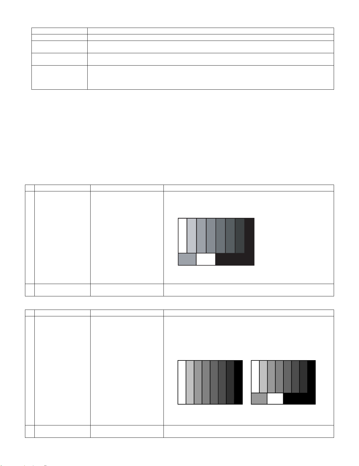
performance
5. ADC adjustment (Component 15K)
Adjustment point Adjustment Conditions Adjustment procedure
1 Setting [Signal]
2 Auto adjustment
performance
6. ADC adjustment (Component 33K)
Adjustment point Adjustment Conditions Adjustment procedure
1 Setting [Signal]
Page 4/33 Bring the cursor on [SECAM ADJ] and press [OK] [SECAM ADJ OK] appears
COMP15K, 50Hz
100% Full Field Colour Bar signal
[Terminal]
EXT8 COMPONENT IN
Page 6/33 Bring the cursor on [COMP15k ALL ADJ] and press [OK] [COMP15k ALL ADJ
COMP33K, 50Hz
100% Full Field Colour Bar signal
when finished.
• Feed the COMPONENT 15K 100% full field colour bar signal (100% colour
saturation) to EXT8 COMPONENT IN.
100% white
OK] appears when finished.
• Feed the COMPONENT 33K 100% full field colour bar signal (100% colour
saturation) to EXT8 COMPONENT IN.
Black
2 Auto adjustment
performance
[Terminal]
EXT8 COMPONENT IN
Page 7/33 Bring the cursor on [HDTV ADJ] and press [OK] [HDTV ADJ OK] appears when
100% white
finished.
Black
3 – 14
Page 95

LC-42XL2E/S/RU, LC-46XL2E/S/RU, LC-46X20E/S/RU, LC-52XL2E/S/RU, LC-52X20E/S/RU
7. DVI-I adjustment (ANALOG D-sub15PIN)
Adjustment point Adjustment Conditions Adjustment procedure
1 Setting [Signal]
XGA 60Hz
100% Full Field Colour Bar signal
[Terminal]
EXT7 PC IN
• Feed the XGA 60Hz 100% full field colour bar signal (100% colour satura-
tion) to EXT7 PC IN.
100% white
Black
2 Auto adjustment
performance
8. RGB adjustment (SCART)
Adjustment point Adjustment Conditions Adjustment procedure
1 Setting [Signal]
2 Auto adjustment
performance
Page 8/33 Bring the cursor on [DVI ANALOG PC ADJ] and press [OK] [DVI ANALOG PC
RGB15K, 50Hz
100% Full Field Colour Bar signal
[Terminal]
EXT1 SCART IN
Page 9/33 Bring the cursor on [SCART RGB ADJ] and press [OK] [SCART RGB ADJ OK]
ADJ OK] appears when finished.
• Feed the RGB15k 50Hz 100% full field colour bar signal (100% colour satu-
ration) to EXT1 SCART IN.
100% white
appears when finished.
Black
10. White Balance Adjustment
Adjustment gradation values (IN) appear on page 12/33 of process adjustment, and adjustment initial values (offset value) appear on pages 13/33
and 14/33.
For white balance adjustment, adjust the offset values on pages 13/33 and 14/33.
[Condition of the unit for inspection]: Modulated light: MAX (+8)
[Adjustment reference device] : Minolta CA-210
[Adjustment]
Check that the values on page 12/33 of process adjustment are set as below. If not, change them accordingly.
Point 1 (LEV1) 176
Point 2 (LEV2) 352
Point 3 (LEV3) 528
Point 4 (LEV4) 656
Point 5 (LEV5) 800
Point 6 (LEV6) 928
1) Display the current adjustment status at point 6. (Page 12/33 of process adjustment)
The display for checking the adjustment status is toggled by pressing the “6” button on the remote control.
(Normal OSD display → “6” → display for check (OSD disappears) → “6” → normal OSD display → . . . )
2) Read the value of the luminance meter. x=0.272, y =0.277
3) Change MG6R/MG6B (Adjustment offset value) on page 14/33 of process adjustment so that the values of the luminance meter approach x=0.272
and y =0.277.
(Basically, G is not changed. If adjustment fails with R and B, change G. When G is lowered, the weaker of R and B must be fixed.)
4) Display the adjustment status of the current point 5. (Each time the “5” button on the remote control is pressed, the adjustment status check display is toggled.)
(Normal OSD display → “5” → Check display (OSD disappears) → “5” → Normal OSD display → . . . )
Change MG5R/MG5B (adjustment offset value) on page 14/33 of process adjustment so that the values of the luminance meter approach x =
0.272 and y = 0.277.
3 – 15
Page 96

LC-42XL2E/S/RU, LC-46XL2E/S/RU, LC-46X20E/S/RU, LC-52XL2E/S/RU, LC-52X20E/S/RU
5) Repeat step 4) for points 4, 3, 2, and 1.
[Adjustment reference standard value]
Adjustment spec ± 0.002 Inspection spec ± 0.004 (point 1 and 2)
Adjustment spec ± 0.001 Inspection spec ± 0.002 (Excluding the above-mentioned)
* Adjusting procedure by use of [RS-232C]
1. Get ready the PC with COM port (RS-232C) running on Windows 95/98/ME/2000/XP operating system, as well as the RS-232C cross cable.
2. Start the unit with the RS-232C cable connected.
3. Start the terminal software. (The freeware readily available on the Internet will do.)
4. Make the following settings.
Baud rate 9,600 bps
Data LENGTH 8 bit
Parity bit None
Stop bit 1 bit
Flow control None
5. If the settings are correct, the terminal software indicates “ERR” against pressing of the “ENTER” key.
6. After the settings are done correctly, it is possible to make an adjustment by typing in the command shown in the table below and pressing the
“ENTER” key on the keyboard.
7. Command entry is successful if the terminal software indicates “OK” when the “ENTER” is pressed. If “ERR” is shown, retry to enter the command.
8. Send the process mode switching command to switch from the RS232C operation mode to the process mode.
KRSW0001: “ERR” is returned.
KKT10037: When “OK” is returned, the process mode becomes active. When “ERR”, start over from KRSW0001.
9. Send each adjustment command.
RS-232C command list
Command Function Remarks
KYOF0000 Remote control disabled
OSDS0001 OSD display inhibited
SBSL0016 Light control level MAX
MSET0001 Background adjustment start
MSET0004 Initialization of adjustment value
LEV60928 Graduation 6 (928-graduation adjustment)
MG6G **** Adjustment of G of graduation 6 0000 ~ 4095
MG6R **** Adjustment of R of graduation 6 0000 ~ 4095
MG6B **** Adjustment of B of graduation 6 0000 ~ 4095
LEV50800 Graduation 5 (800-graduation adjustment)
MG5G **** Adjustment of G of graduation 5 Calculated value
MG5R **** Adjustment of R of graduation 5 0000 ~ 4095
MG5B **** Adjustment of B of graduation 5 0000 ~ 4095
LEV40656 Graduation 4 (656-graduation adjustment)
MG4G **** Adjustment of G of graduation 4 Calculated value
MG4R **** Adjustment of R of graduation 4 0000 ~ 4095
MG4B **** Adjustment of B of graduation 4 0000 ~ 4095
LEV30528 Graduation 3 (528-graduation adjustment)
MG3G **** Adjustment of G of graduation 3 Calculated value
MG3R **** Adjustment of R of graduation 3 0000 ~ 4095
MG3B **** Adjustment of B of graduation 3 0000 ~ 4095
LEV20352 Graduation 2 (352-graduation adjustment)
MG2G **** Adjustment of G of graduation 2 Calculated value
MG2R **** Adjustment of R of graduation 2 0000 ~ 4095
MG2B **** Adjustment of B of graduation 2 0000 ~ 4095
LEV10184 Graduation 1 (176-graduation adjustment)
MG1G **** Adjustment of G of graduation 1 Calculated value
MG1R **** Adjustment of R of graduation 1 0000 ~ 4095
MG1B **** Adjustment of B of graduation 1 0000 ~ 4095
MSET0003 Writing of adjustment value
3 – 16
Page 97

LC-42XL2E/S/RU, LC-46XL2E/S/RU, LC-46X20E/S/RU, LC-52XL2E/S/RU, LC-52X20E/S/RU
30%
0%
11. Confirmation item
1. Magi-Link Inspection
The thing that the Magi-Link circuit operates is confirmed.
2. HDMI-CEC Inspection
The thing that the HDMI-CEC circuit operates is confirmed.
12. Initialization to factory settings
CAUTION: When the factory settings have been made, all user setting data, including the channel settings, are initialized.
1 Factory settings ends by turning off the
After adjustments, exit the adjustment process mode.
To exit the adjustment process mode, turn off the MAIN power key.
When the power is turned off with the remote control, unplug the AC power cord and plug it back in.
(The adjustments done in the adjustment process mode are not initialized.) Keep this in mind when initializing these settings.
Adjustment item Adjustment conditions Adjustment procedure
[Factory setting with adjustment process mode]
MAIN POWER key.
(See to below caution)
• Enter the adjustment process mode.
• Move the cursor to [INDUSTRY INIT] on page 2/33.
• Use the R/C key to select a region from [EUROPE/RUSSIA/SWEDEN] and press the
[OK] key.
• “EXECUTING” display appears.
• After a while, “SUCCESS” display appears, the setting is completed.
When succeeding: Background color (green)
When failing: Background color (red)
The following items are initialized in the factory setting.
1) User settings
2) Channel data (e.g. broadcast frequencies)
3) Maker option setting
4) Password data
13. Upgrading the software
1. Turn off the AC power (Unplug the AC power cord).
2. Insert the upgrading USB flash memory for upgrade into the service slot.
3. While holding down the power button, plug in the AC power cord of the main unit to turn on the power.
4. Upgrade begins automatically.
After the set starts, the upgrade screen like the figure below is displayed.
<SYSTEM UPGRADE>
System Version: E0708021
BANK 1
BANK 2
STATUS
UPDATING. . .
3 – 17
Page 98

LC-42XL2E/S/RU, LC-46XL2E/S/RU, LC-46X20E/S/RU, LC-52XL2E/S/RU, LC-52X20E/S/RU
100%
44%
100%
100%
5. If any of the procedures fails, the following upgrade failure screen shows up. For the failing procedure, the “NG” marking turns red.
NOTE: In such case, try to upgrade the software again. If it still fails, the hardware may be in trouble.
<SYSTEM UPGRADE>
System Version: E0708021
BANK 1
OK
BANK 2
STATUS
UPDATING. . .
6. When all the procedures are complete, the following upgrade success screen shows up. The new software version can be confirmed on screen.
The version number appears when each item has been successfully upgraded. Finally the main version number appears on screen.
<SYSTEM UPGRADE>
System Version: E0708021
BANK 1
OK
BANK 2
OK
STATUS
UPGRADE COMPLETE
7. Turn off the AC power (Unplug the AC power cord). Take out the upgrading USB flash memory.
8. Now the software has been upgraded.
NOTE: Then get the set started and call the process adjustment screen 1/33 to check the main software version.
CAUTION
1) Do not take out and put in the USB flash memory during formatting.
2) It takes about one minute to the rewriting completion.
Please confirm the upgrade status on the screen becomes 100%.
3 – 18
Page 99

LC-42XL2E/S/RU, LC-46XL2E/S/RU, LC-46X20E/S/RU, LC-52XL2E/S/RU, LC-52X20E/S/RU
LC42XL2E
CHAPTER 4. TROUBLESHOOTING TABLE
Service Manual
[1] TROUBLESHOOTING TABLE
Power unit operation check.
Are the power cord and harness in the unit properly connected? NO Connect the power cord and harness properly, and turn on the
power.
LINE_FILTER_UNIT: YES
Is F7000 normal?
POWER_UNIT YES
Is B_BUS (+320V) output? (Set the main power SW to OFF.)
* When power on/off switch is on • • • About +400V
NO
NO Does the PFC circuit operate normally?
LINE_FILTER_UNIT:
Isn't FL7001, L7001, R7002, CX7000-1, Z7000, etc. out of order?
Moreover, whether the short-circuit with the circumference circuit
is checked.
POWER_UNIT:
BD7000, TH7000-1, IC7801,Z7800, etc. out of order?
Moreover, whether the short-circuit with the circumference circuit
is checked.
(L7800, L7801, T7800, D7806, Q7804-5, IC7800-1 and etc. And,
the circuit around the protection circuit etc. is checked.)
YES
Is a voltage of BU5V applied to pin (8) of connector (PD)?
(Set the main power SW to OFF.)
YES
Are INV60V, UR15, and S15V output as for the power on/off
switch when it is on?
YES
Similarly, is PNL12V output as for the power on/off switch when it
is on?
NO Does the switching circuit operate normally?
Check circuit around the primary side (T7901, IC7905, Q7902,
Q7912-3, D7908-9, D7904, D7910, etc.), the secondary side
(D7918, L7900, etc.), the AC_DET circuit (D7911-2, IC7909,
IC7902, Q7910, Q7901, etc.), and the protection circuit.
NO Does the inverter circuit operate normally?
Check circuit around the primary side (T7001, T7601, IC7603,
IC7601, IC7600, Q7600-2, D7608, D7610, D7613, etc.), the secondary side (D7560-3, L7560, D7150-1, L7150, L7152, Q7911,
etc.), the PS_ON circuit (Q7300-1, etc.), and the protection circuit.
NO Check PNL_POW circuit of Q7121-2, etc. and the circuit around
the regulator circuit etc. of IC7121, L7121, D7121, etc.
4 – 1
Page 100

LC-42XL2E/S/RU, LC-46XL2E/S/RU, LC-46X20E/S/RU, LC-52XL2E/S/RU, LC-52X20E/S/RU
The sound is not emitted from the speaker though the picture has come out.
No sound output in all modes?
TEREMINAL UNIT:
Is the audio signal output of pins (38) (L-ch) and (39) (R-ch) of
IC1404 (CODEC) normal?
YES
Is audio signal input to pin (5/L), pin (9/R) of IC1301 (AMP)? NO Check the line between IC1404 and IC1301.
YES
Is MUTE circuit [SP_MUTE_LINE, S_STBY_LINE] normal? NO Check the SP_MUTE_LINE and S_STBY_LINE.
YES
Is the audio signal output of pins (2, 1) (L-ch) and (3, 4) (R-ch) of
P1301(AOUDIO-CONNECTOR) normal?
YES
Check Speaker Box (right and left) and wire harness.
NO Check IC1404 and its peripheral circuits.
(Q1302, etc.)
NO Check IC1301 and its peripheral circuits.
No sound (during the reception of TV(ANALOG) broadcasting)
Does not the sound go out though the picture has come out when UHF/VHF is received?
TEREMINAL UNIT:
Is the IF signal output from pin (17) of TUNER (TU7501)? NO Check the tuner and its peripheral circuits.
Replace as required.
YES
Is the SIF signal sent to pins (23) and (24) of IC7504 (IFDEMOD)?
YES
Is the SIF signal input from pin (12) of IC7504 to pin (3) of IC1402
(SOUND MULTIPLEX DECODER)?
YES
Is audio signal input from pin (24/L-ch), (22/R-ch) of IC1402 to
pin (61, 62) of IC1404 (CODEC)?
YES
Refer to “No sound output in all modes”.
NO Check FL7501 and its peripheral circuits.
NO Check the line between IC7504 and IC1402.
(Q7504, etc.)
NO Check the line between IC1402 and IC1404.
4 – 2
 Loading...