

Page 1
TopPage
LC-40L550/650M
SERVICE MANUAL
No. S80I8LC40L65M
LCD COLOUR TELEVISION
LC-40L550M
MODELS
In the interests of user safety (required by safety regulations in some countries) the set should be restor ed to its
original condition and only parts identical to those specified should be used.
LC-40L650M
OUTLINE
This model is based on the LC-40L500M and partially modified.
For the contents not covered in this Service Manual, accordingly, please refer to the LC-40L500M
(No. S60G6LC40L50M) Service Manual.
CONTENTS
OUTLINE AND DIFFERENCES FROM BASE MODEL
OUTLINE.............................................................i
DIFFERENCES FROM BASE MODEL...............i
SAFETY PRECAUTION
IMPORTANT SERVICE SAFETY PRE-
CAUTION...........................................................ii
PRECAUTIONS FOR USING LEAD-FREE
SOLDER ...........................................................iii
CHAPTER 4. REMOVING OF MAJOR PARTS
[1] REMOVING OF MAJOR PARTS...................4-1
CHAPTER 5. OVERALL WIRING/BLOCK DIAGRAM
[1] OVERALL WIRING DIAGRAM......................5-1
[2] SYSTEM BLOCK DIAGRAM (LC-
40L550M) ......................................................5-2
[3] SYSTEM BLOCK DIAGRAM (LC-
40L650M) ......................................................5-3
MAJOR SERVICE PARTS
MAJOR SERVICE PARTS............... .... .............iv
CHAPTER 1. SPECIFICATIONS
[1] SPECIFICATIONS .........................................1-1
CHAPTER 2. OPERATION MANUAL
[1] OPERATION MANUAL..................................2-1
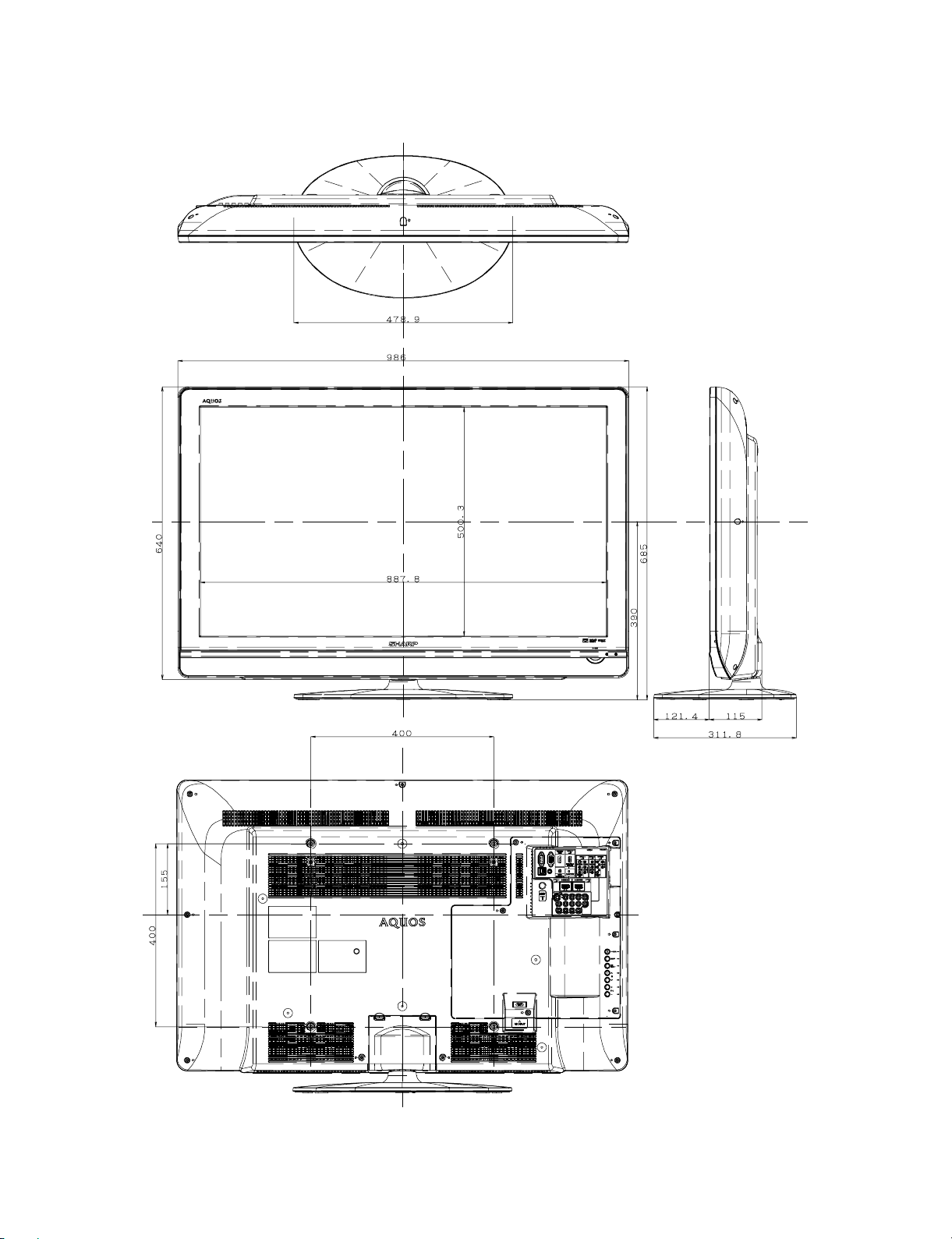
CHAPTER 3. DIMENSIONS
[1] DIMENSIONS ................................................3-1
Parts marked with " " are important for maintaining the safety of the set. Be sure to replace these parts with specified ones for maintaining the
safety and performance of the set.
CHAPTER 6. SCHEMATIC DIAGRAM
[1] DESCRIPTION OF SCHEMATIC DIA-
GRAM............................................................6-1
[2] MAIN Unit ......................................................6-2
Parts Guide
This document has been published to be used for
after sales service only.
The contents are subject to change without notice.
Page 2
LC-40L550/650M
LC40L550M
OUTLINE AND DIFFERENCES FROM BASE MODEL
ServiceManual
OUTLINE
This model is based on the LC-40L500M and partially modified.
For the contents not covered in this Service Manual, accordingly, please refer to the LC-40L500M (No. S60G6LC40L50M) Service Manual.
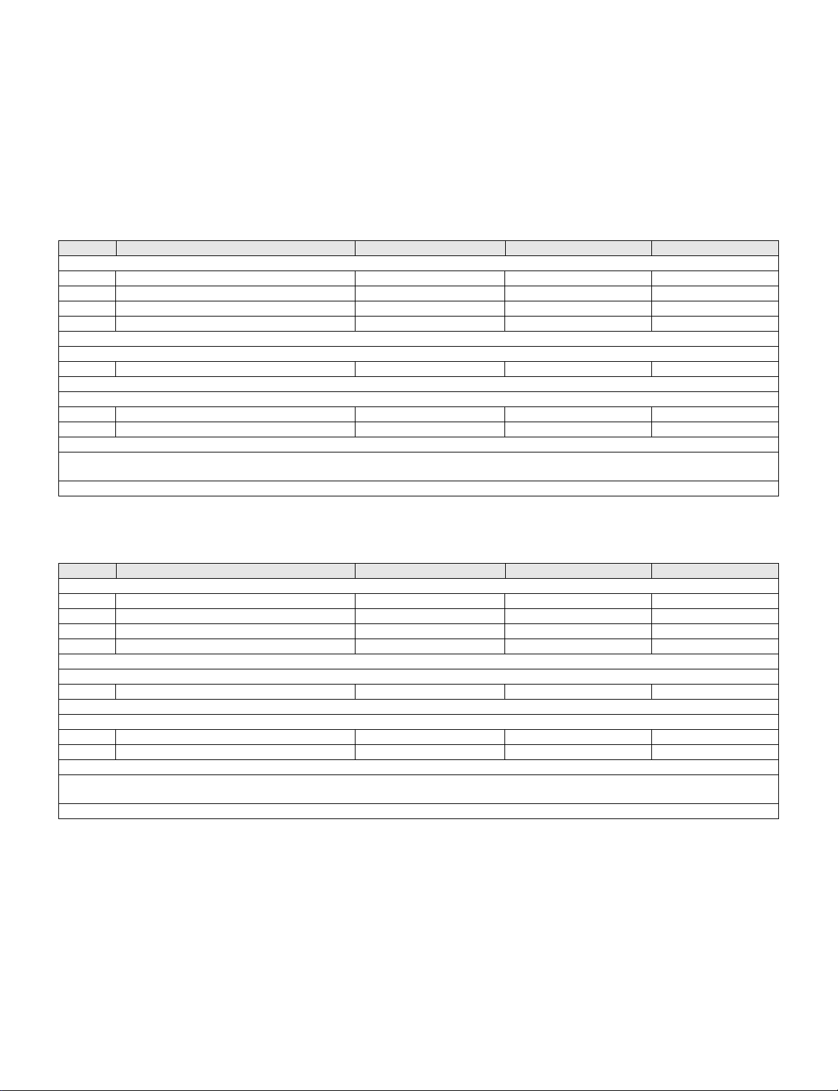
DIFFERENCES FROM BASE MODEL
LIST OF CHANGED PARTS (LC-40L550M)
Ref. No. Description LC-40L500M LC-40L550M Note
PRINTED WIRING BOARD ASSEMBLIES
N MAIN Unit (except Philippines) DUNTKF541FM02 DKEYMF541FM06 Changed
N MAIN Unit (for Philipines) DUNTKF541FM12 DUNTKF541FM16 Changed
N R/C, LED Unit DUNTKF573FM01 DUNTKF573FM02 Some parts changed
N POWER Unit RDENCA408WJQZ ← —
LCD PANEL
N LCD Panel Module Unit R1LK400D3LWL0W ← —
R/C, LED Unit
D103 Diode RH-PXA194WJQZY RH-PXA192WJQZY Changed
R108 Resistor VRS-CY1JF181JY VRS-CY1JF182JY Changed
MAIN Unit, CABINET PARTS, SUPPLIED ACCESSORIES, PACKING PARTS (NOT REPLACEMENT ITEM),
SERVICE JIGS (USE FOR SERVICING)
Please refer to a Parts list.
LIST OF CHANGED PARTS (LC-40L650M)
Ref. No. Description LC-40L500M LC-40L650M Note
PRINTED WIRING BOARD ASSEMBLIES
N MAIN Unit (except Philippines) DUNTKF541FM02 DKEYMF541FM08 Changed
N MAIN Unit (for Philipines) DUNTKF541FM12 DUNTKF541FM18 Changed
N R/C, LED Unit DUNTKF573FM01 DUNTKF573FM02 Some parts changed
N POWER Unit RDENCA408WJQZ ← —
LCD PANEL
N LCD Panel Module Unit R1LK400D3LWL0W R1LK400D3GW20W Changed
R/C, LED Unit
D103 Diode RH-PXA194WJQZY RH-PXA192WJQZY Changed
R108 Resistor VRS-CY1JF181JY VRS-CY1JF182JY Changed
MAIN Unit, CABINET PARTS, SUPPLIED ACCESSORIES, PACKING PARTS (NOT REPLACEMENT ITEM),
SERVICE JIGS (USE FOR SERVICING)
Please refer to a Parts list.
i
Page 3

LC-40L550/650M
LC40L550M
SAFETY PRECAUTION
ServiceManual
IMPORTANT SERVICE SAFETY PRECAUTION
Service work should be performed only by qualified service technicians who are thoroughly familiar with all safety checks and the
servicing guidelines which follow:
WARNING
1. For continued safety, no modification of any circuit should be
attempted.
2. Disconnect AC power before servicing.
BEFORE RETURNING THE RECEIVER (Fire &
All checks must be repeated with the AC cord plug connection
reversed. (If necessary, a nonpolarized adaptor plug must be used
only for the purpose of completing these checks.)
Any reading of 0.74 Vrms (this corresponds to 0.5 mA rms AC.) or
more is excessive and indicates a potential shock hazard which
must be corrected before returning the monitor to the owner.
Shock Hazard)
Before returning the receiver to the user, perform the following
safety checks:
3. Inspect all lead dress to make certain that leads are not pinched,
and check that hardware is not lodged between the chassis and
other metal parts in the receiver.
4. Inspect all protective devices such as non-metallic control knobs,
insulation materials, cabinet backs, adjustment and compartment
covers or shields, isolation resistor-capacitor networks, mechanical
insulators, etc.
5. To be sure that no shock hazard exists, check for leakage current in
the following manner.
• Plug the AC cord directly into a 110-240 volt AC outlet.
• Using two clip leads, connect a 1.5k ohm, 10 watt resistor paralleled by a 0.15µF capacitor in series with all exposed metal cabinet
parts and a known earth ground, such as electrical conduit or electrical ground connected to an earth ground.
• Use an AC voltmeter having with 5000 ohm per volt, or higher, sensitivity or measure the AC voltage drop across the resistor.
• Connect the resistor connection to all exposed metal parts having a
return to the chassis (antenna, metal cabinet, screw heads, knobs
and control shafts, escutcheon, etc.) and measure the AC voltage
drop across the resistor.
///////////////////////////////////////////////////////////////////////////////////////////////////////////////////////////////////////////////////////////////////////////////////////////////////////////////////////////////////////////
TO EXPOSED
METAL PARTS
DVM
AC SCALE
1.5k ohm
10W
0.15µF
TEST PROBE
CONNECT TO
KNOWN EARTH
GROUND
SAFETY NOTICE
Many electrical and mechanical parts in LCD colour television have
special safety-related characteristics.
These characteristics are often not evident from visual inspection, nor
can protection afforded by them be necessarily increased by using
replacement components rated for higher voltage, wattage, etc.
Replacement parts which have these special safety characteristics are
identified in this manual; electrical components having such features
are identified by " " and shaded areas in the Replacement Parts List
and Schematic Diagrams.
///////////////////////////////////////////////////////////////////////////////////////////////////////////////////////////////////////////////////////////////////////////////////////////////////////////////////////////////////////////
For continued protection, replacement parts must be identical to those
used in the original circuit.
The use of a substitute replacement parts which do not have the same
safety characteristics as the factory recommended replacement parts
shown in this service manual, may create shock, fire or other hazards.
ii
Page 4
LC-40L550/650M
PRECAUTIONS FOR USING LEAD-FREE SOLDER
Employing lead-free solder
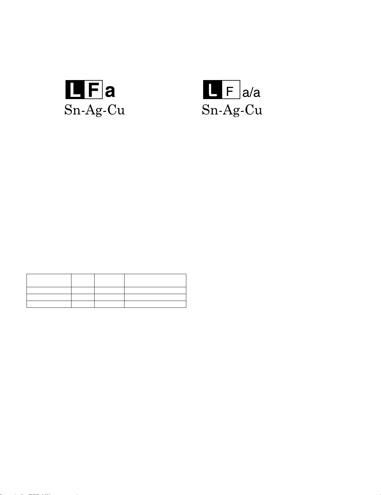
• “PWBs” of this model employs lead-free solder. The LF symbol indicates lead-free solder, and is attached on the PWBs and service manuals. The
alphabetical character following LF shows the type of lead-free solder.
Example:
Indicates lead-free solder of tin, silver and copper. Indicates lead-free solder of tin, silver and copper.
Using lead-free wire solder
• When fixing the PWB soldered with the lead-free solder, apply lead-free wire solder. Repairing with conventional lead wire solder may cause damage or accident due to cracks.
As the melting point of lead-free solder (Sn-Ag-Cu) is higher than the lead wire solder by 40 °C, we recommend you to use a dedicated soldering
bit, if you are not familiar with how to obtain lead-free wire solder or soldering bit, contact our service station or service branch in your area.
Soldering
• As the melting point of lead-free solder (Sn-Ag-Cu) is about 220 °C which is higher than the conventional lead solder by 40 °C, and as it has poor
solder wettability, you may be apt to keep the soldering bit in contact with the PWB for extended period of time. However, Since the land may be
peeled off or the maximum heat-resistance temperature of parts may be exceeded, remove the bit from the PWB as soon as you confirm the
steady soldering condition.
Lead-free solder contains more tin, and the end of the soldering bit may be easily corroded. Make sure to turn on and off the power of the bit as
required.
If a different type of solder stays on the tip of the soldering bit, it is alloyed with lead-free solder. Clean the bit after every use of it.
When the tip of the soldering bit is blackened during use, file it with steel wool or fine sandpaper.
• Be careful when replacing parts with polarity indication on the PWB silk.
Lead-free wire solder for servicing
PARTS CODE
ZHNDAi123250E BL J φ0.3mm 250g (1roll)
ZHNDAi126500E BK J φ0.6mm 500g (1roll)
ZHNDAi12801KE BM J φ1.0mm 1kg (1roll)
PRICE
RANK
PART
DELIVERY
DESCRIPTION
iii
Page 5
LC-40L550/650M
LC40L550M
MAJOR SERVICE PARTS
ServiceManual
MAJOR SERVICE PARTS
PWB Unit
Ref No. Part No. Description
N DKEYMF541FM06 MAIN Unit (except Philippines) (LC-40L550M)
N DUNTKF541FM16 MAIN Unit (for Philippines) (LC-40L550M)
N DKEYMF541FM08 MAIN Unit (except Philippines) (LC-40L650M)
N DUNTKF541FM18 MAIN Unit (for Philippines) (LC-40L650M)
N DUNTKF573FM02 R/C, LED Unit
N RDENCA408WJQZ POWER Unit
OTHER Unit
Ref No. Part No. Description
N R1LK400D3LWL0W LCD Panel Module (LC-40L550M)
N R1LK400D3GW20W LCD Panel Module (LC-40L650M)
IC FOR EXCLUSIVE USE OF THE SERVICE
Ref No. Part No. Description Q'ty
IC508 RH-iXD172WJQZS IC PC EDID 1
IC1503 RH-iXD173WJQZS IC HDMI-1 EDID 1
IC1504 RH-iXD175WJQZS IC HDMI-3 EDID 1
IC1505 RH-iXD174WJQZS IC HDMI-2 EDID 1
SERVICE JIGS
Ref No. Part No. Description Q'ty
N QCNW-L078WJQZ Extension Cable, Main to LCD Control (LW) (LC-40L550M) 1
N QCNW-L079WJQZ Extension Cable, Main to LCD Control (LW) (LC-40L650M) 1
N QCNW-K814WJQZ Extension Cable, Power to Inverter (PI) 1
N QCNW-G445WJQZ Extension Cable, Main to Speaker (SP) 1
iv
Page 6
LC-40L550/650M
LC40L550M
CHAPTER 1. SPECIFICATIONS
[1] SPECIFICATIONS
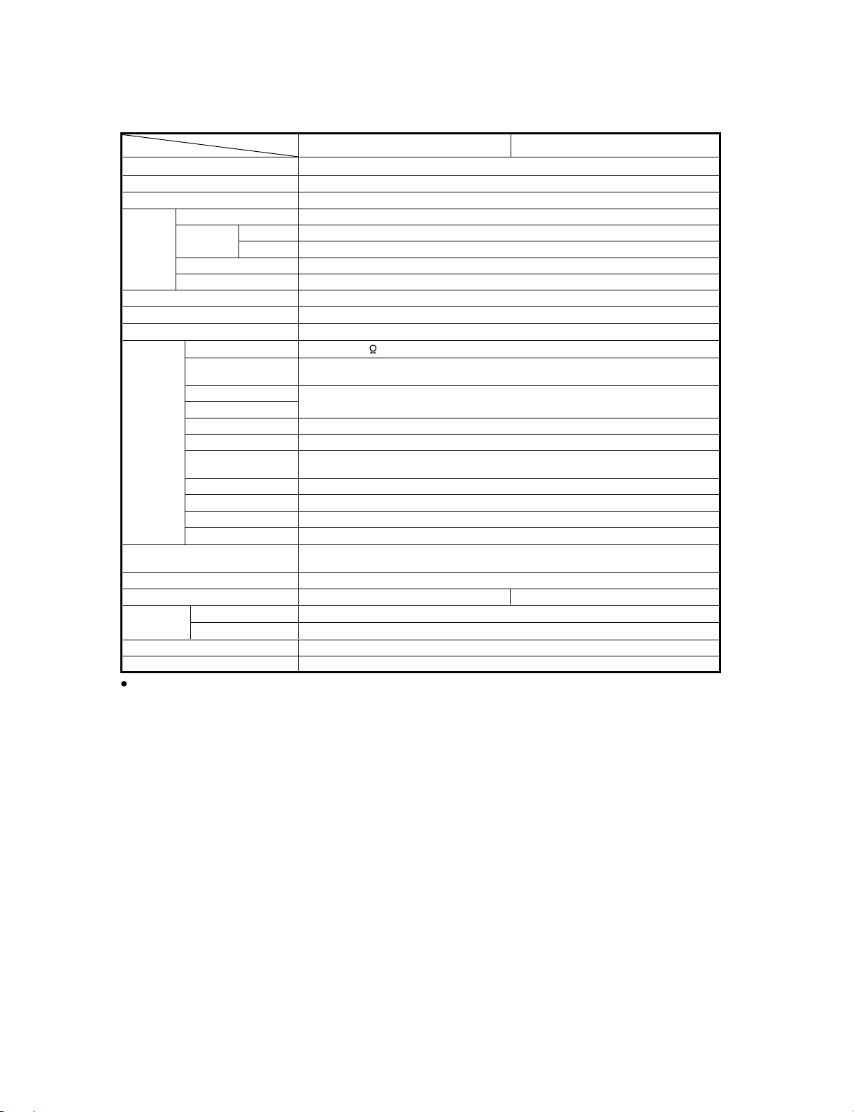
Item Model LC-40L550M LC-40L650M
LCD panel
Resolution
Video Colour System PAL/SECAM/NTSC 3.58/NTSC 4.43/PAL 60
TV
Function
Viewing angles H : 176º V : 176º
Audio amplifier
Speakers
Terminals Antenna input
TV-Standard PAL: B/G, D/K, I SECAM: B/G, D/K, K/K
Receiving
Channel
TV-Tuning System Auto Preset 99 ch
STEREO/BILINGUAL NICAM: B/G, I, D/K A2 stereo: B/G M: MTS
INPUT 1 HDMI (HDMI input) (480I, 576I, 480P, 576P, 720P/50Hz, 720P/60Hz, 1080I/50Hz,
INPUT 2
INPUT 3
INPUT 4 S-VIDEO in, VIDEO in, AUDIO in
INPUT 5 VIDEO in, AUDIO in
INPUT 6 AUDIO in, COMPONENT in (480I, 576I, 480P, 576P, 720P/50Hz, 720P/60Hz,
INPUT 7 (PC input)
USB USB
RS-232C 9 pin D-sub male connector
VHF/UHF 44.25 — 863.25 MHz
CATV S1 — S41ch (including Hyperband)
DIGITAL AUDIO OUTPUT
OSD language English/Simplified Chinese/Arabic/French/Portuguese/Russian/Persian/Thai/
Power Requirement AC 110 — 240 V, 50/60 Hz
Power Consumption 169 W (0.9 W Standby) 171 W (0.9 W Standby)
Dimensions
Weight without stand (with stand) 15.5 kg (16.5 kg)
Operating Temperature 0°C — 40°C
As a part of policy of continuous improvement, SHARP reserves the right to make design and specification changes for
product improvement without prior notice. The performance specification figures indicated are nominal values of production
units. There may be some deviations from these values in individual units.
without stand (mm)
with stand (mm)
40" (1016 mm) Advanced Super View & BLACK TFT LCD
2,073,600 pixels (1920 x 1080)
10 W x 2
9x5cm 2pcs
UHF/VHF 75
1080I/60Hz, 1080P/50Hz, 1080P/60Hz, 1080P/24Hz), AUDIO in (㱢 3.5 mm jack)
HDMI (HDMI input) (480I, 576I, 480P, 576P, 720P/50Hz, 720P/60Hz, 1080I/50Hz,
1080I/60Hz, 1080P/50Hz, 1080P/60Hz, 1080P/24Hz)
1080I/50Hz, 1080I/60Hz, 1080P/50Hz, 1080P/60Hz)
15 pin mini D-sub, AUDIO in (common use with INPUT 1) (
Optical Digital Audio Output
Vietnamese/Indonesian
986 (W) x 640 (H) x 115 (D)
986 (W) x 685 (H) x 311.8 (D)
DIN type
ServiceManual
1
NTSC: M
㱢
3.5 mm jack)
1 – 1
Page 7
LC40L550M
CHAPTER 2. OPERATION MANUAL
[1] OPERATION MANUAL
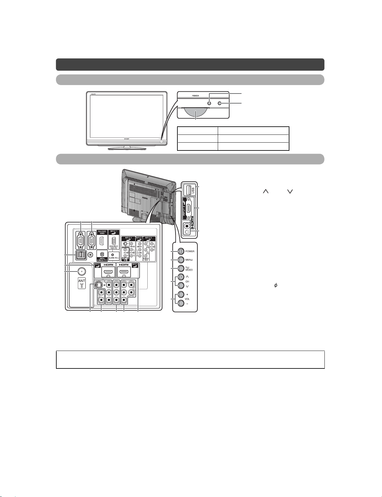
Part names
TV (Front)
TV (Rear)
A
C
I
N
P
U
6 7
8
9
10
T
1
2
3
4
5
ServiceManual
OPC sensor
Remote control sensor
POWER indicator
Light off Power off
Lighted (Red) The TV is in standby mode.
Lighted (White) The TV is on.
1 POWER (On/Off) button
2MENUbutton
16
17
18
3 TV/VIDEO button
4 Channel up( )/down ( ) buttons
5 Volume up (+)/down (-) buttons
6 RS-232C terminal
7 INPUT 7 (PC) terminals*
8 DIGITAL AUDIO OUTPUT terminal
9 INPUT 1 (HDMI) terminal
10 Antenna input terminal*
11 INPUT 4 terminals
12 MONITOR OUT terminals
13 INPUT 5 terminals
14 INPUT 6 terminals
15 INPUT 2 (HDMI) terminal
16 USB terminal**
17 INPUT 3 (HDMI) terminal
18 Headphone jack(
• The speakers do not output volume
when headphones are plugged in.
LC-40L550/650M
3.5 mm)
1211
13 14 15
* The INPUT 1 and INPUT 7 terminals can both use the same audio input terminal. However, the proper item must be
selected in the “PC audio select” menu.
**USB terminal use for USB Media Player. Please see “USB Media Player Operation Manual” in separate sheet.
• The illustrations in this operation manual are for explanation purposes and may vary slightly from the actual operations.
• The illustrations used throughout this manual are based on LC-40L550M.
2 – 1
Page 8
LC-40L550/650M
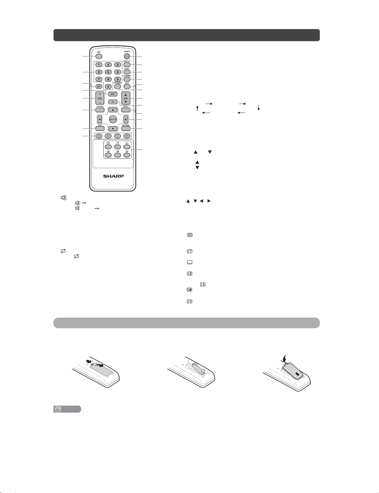
Remote control unit
1 (Mute)
Press Mutes sound.
Press again Restores sound.
Mute will be cancelled after 30 minutes. However,
the TV will not suddenly output loud sound as the
volume level will be set to 0 automatically. Increase
the volume level by pressingVOL +.
2 0–9
Set the channel.
TELETEXT mode: Set the page.
3 (Flashback)
Press to return to the previous selected channel
or external input mode.
4WIDE
Change the wide image mode.
5 VOL +/VOL -
Set the volume.
(VOL +)Increase the volume.
(VOL - ) Decrease the volume.
6 FREEZE
Freeze a motion picture on the screen.
7 EXIT
1
9
10
2
3
4
5
6
11
12
13
14
15
16
17
18
7
19
8
20
Return to the default screen.
8 Colour (Red/Green/Yellow/Blue)
TELETEXT mode: Select a page.
9 POWER (STANDBY/ON)
To switch the power on and off.
10 DISPLAY
Display the channel or input information.
11 SLEEP
Set the Sleep timer.
0hr.30min. 1hr.00min.
Off
12 AV MODE
Select an audio and video setting.
13 MPX
Select the sound multiplex mode.
14 TV/VIDEO (INPUT SOURCE)
Select an input source.
15 CH /C H
TV input mode: Select the channel.
(CH ) Increase the channel number.
(CH ) Decrease the channel number.
TELETEXT mode: Select the page.
16 PC
Directly select the PC terminal.
17 MENU
Display the menu screen.
18 /// (Cursor)
Select a desired item on the setting screen.
ENTER
Execute a command.
19 RETURN
MENU mode: Return to the previous menu screen.
20 (TELETEXT)
Select the TELETEXT mode. (all TV image, all TEXT image,
TV/TEXT image)
(Reveal hidden for TELETEXT)
TELETEXT mode: Display hidden characters.
(SUBTITLE for TELETEXT)
To turn the subtitles on.
(Hold)
TELETEXT mode: Stop updating Teletext pages automatically.
Press again to release the hold mode.
(Subpage)
Display the Teletext subpage directly when in Teletext mode.
(Top/Bottom/Full)
TELETEXT mode: Set the area of magnification.
2hr.30min.
1hr.30min.
2hr.00min.
Inserting the battery
Before using the TV for the first time, insert a “AA” size battery (supplied). When the battery become depleted
and the remote control fails to operate, replace the battery with new “AA” size battery.
Open the battery cover.
1
CAUTION
• Battery (battery pack or battery installed) shall not be exposed to excessive heat such as sunshine, fire or the like.
Insert the supplied “AA” size battery.
2
•
Place battery with their terminals corresponding to the
(+) and (-) indications in the battery compartment.
Close the battery cover.
3
2 – 2
Page 9
LC-40L550/650M
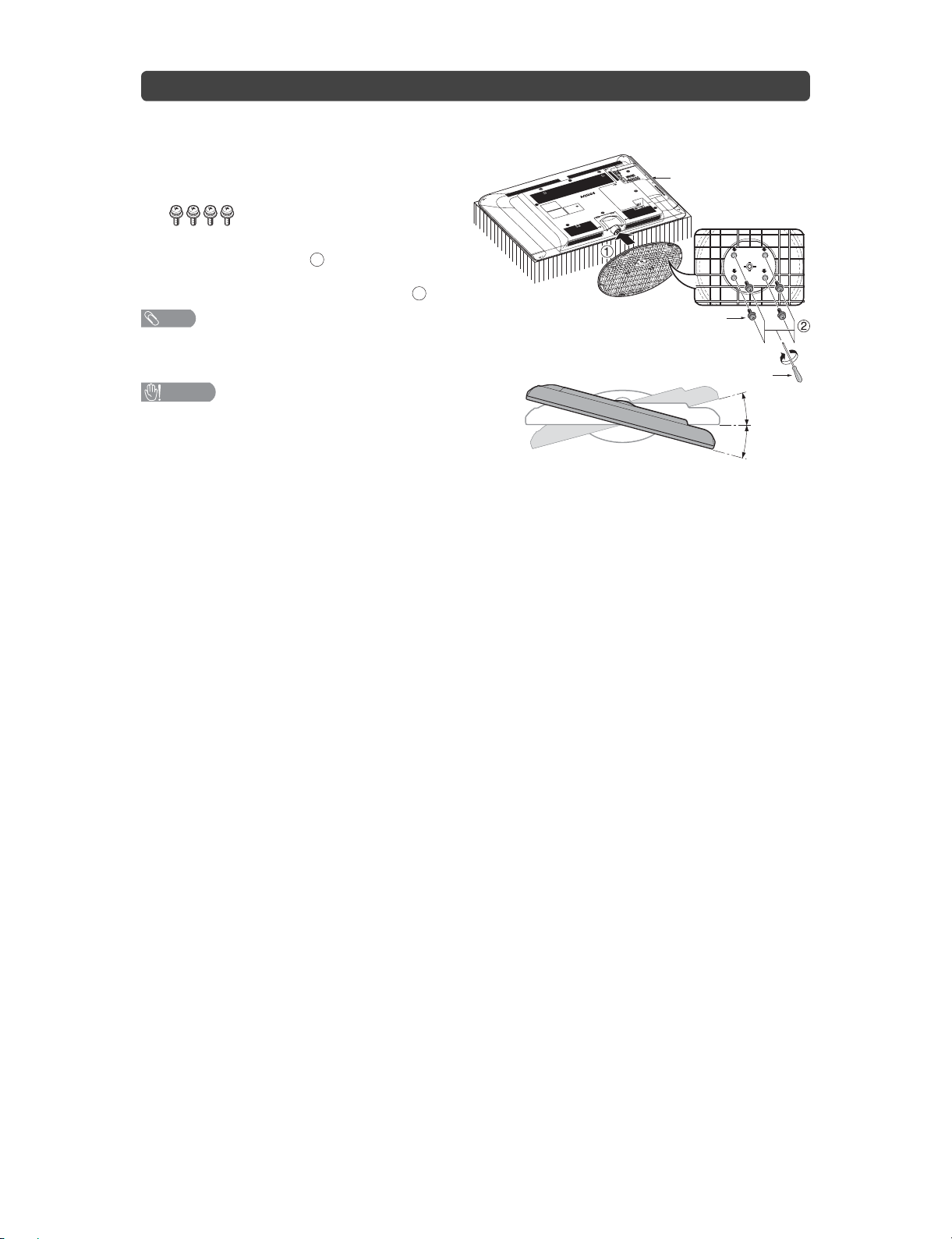
Attaching the stand
• Before attaching (or detaching) the stand, unplug the AC cord from the AC outlet.
• Before performing work spread cushioning over the base area to lay the TV on. This will prevent it from
being damaged.
Confirm the screws supplied with the TV.
1
Screws (x4)
(used in step 3)
Insert the stand base to the stand post on
2
the bottom of the TV.(1)
Insert and tighten the 4 screws into the 4
3
holes on the bottom of the stand base.(2)
NOTE
• To detach the stand, perform the steps in reverse
order.
CAUTION
• Adjust the screen with both hands. Put one hand on the TV
and rotate the screen while steadying the stand with your
other hand.
The TV can be rotated up to 15 degrees to the right or left.
Soft cushion
Screw
Screw driver
15°
15°
2 – 3
Page 10
LC-40L550/650M
LC40L550M
CHAPTER 3. DIMENSIONS
[1] DIMENSIONS
ServiceManual
Unit: mm
3 – 1
Page 11
LC40L550M
CHAPTER 4. REMOVING OF MAJOR PARTS
ServiceManual
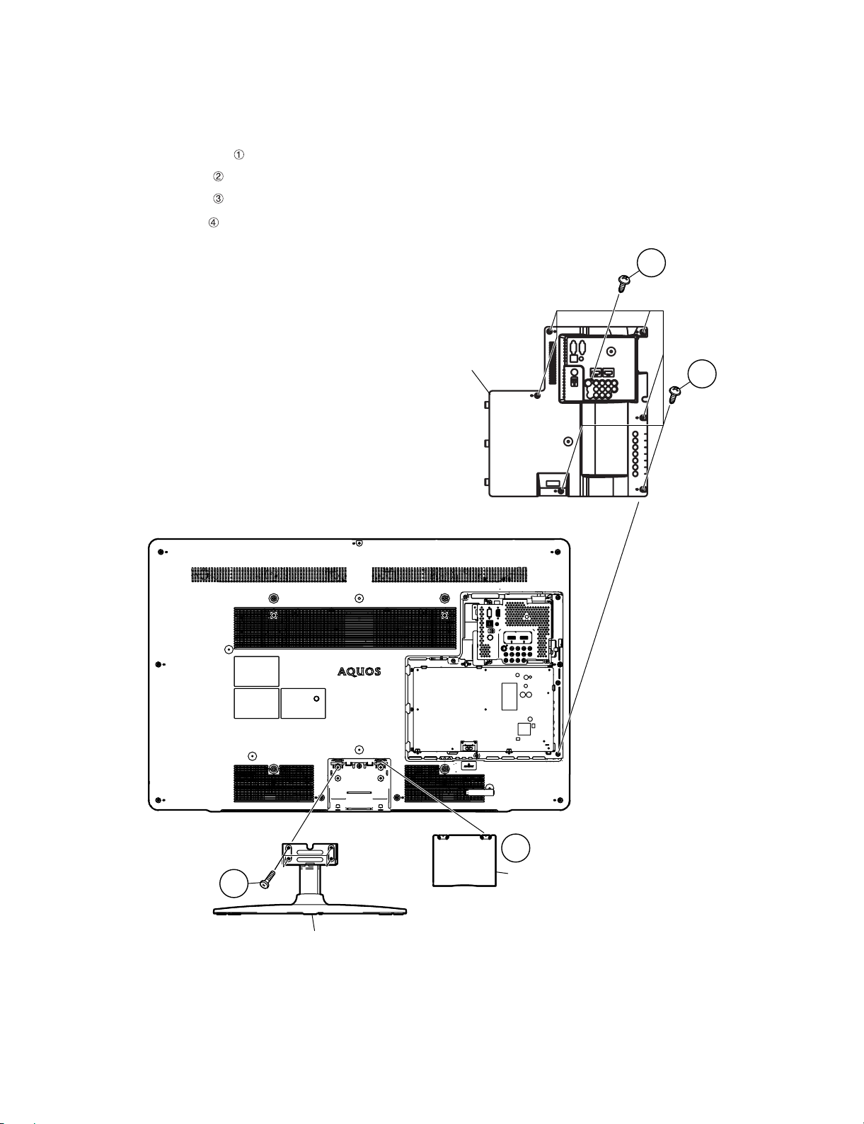
[1] REMOVING OF MAJOR PARTS
1. Removing of the Stand and Back Cover Ass’y
1. Detach the Stand Hinge Cover .
2. Remove the 4 lock screws and detach the Stand.
3. Remove the 6 lock screws .
4. Remove the 1 lock screw and detach the Back Cover Ass’y.
LC-40L550/650M
4
Back Cover Ass'y
3
1
2
Stand Hinge Cover
Stand
4 – 1
Page 12
LC-40L550/650M
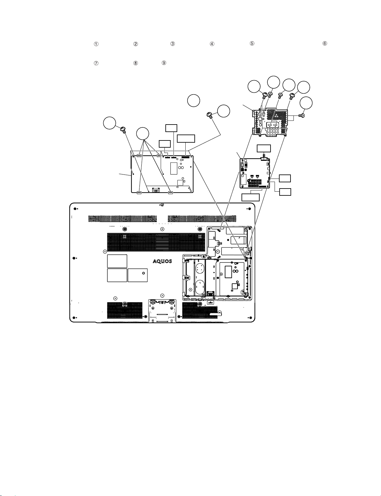
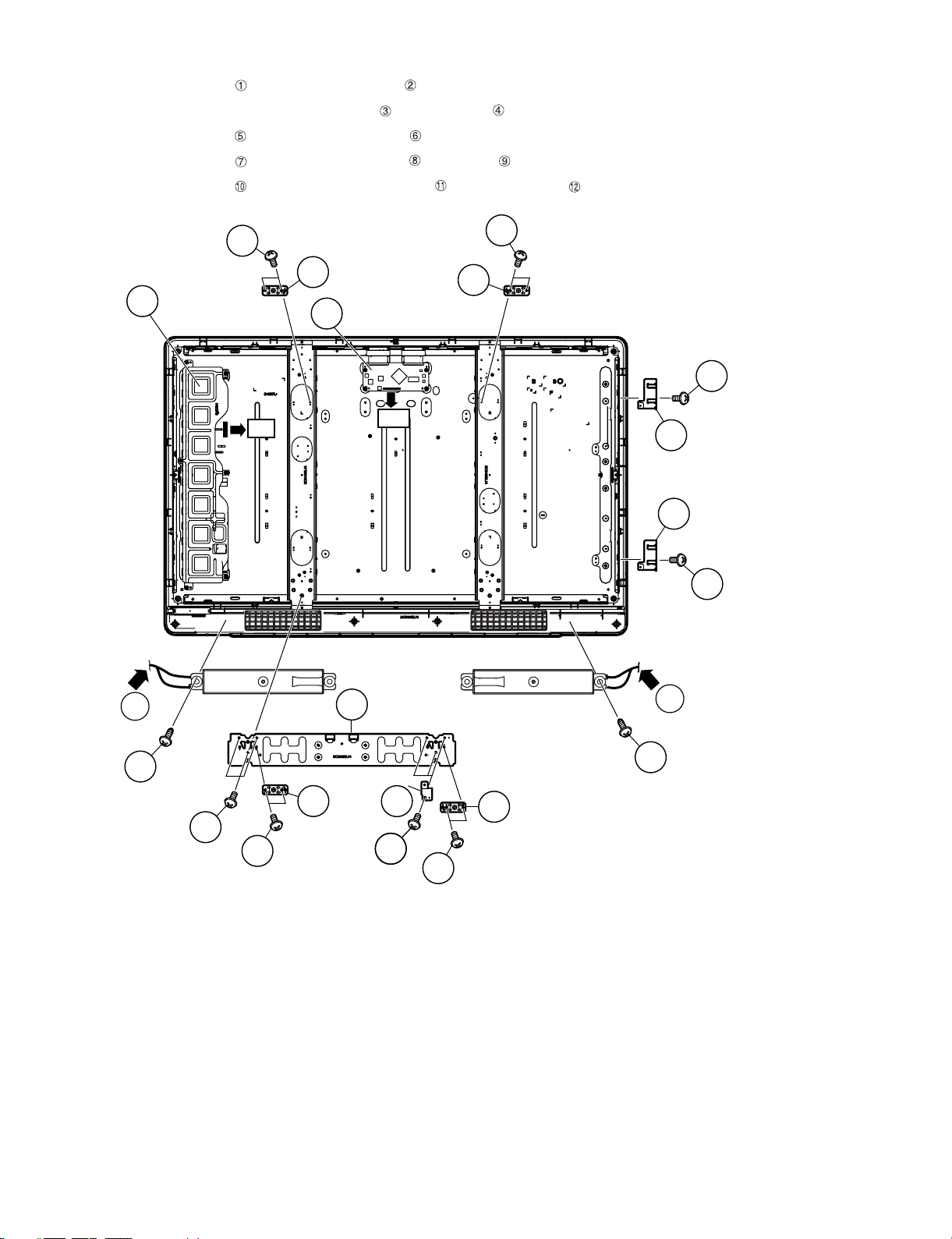
2. Removing of the MAIN Shield, MAIN Unit, POWER Unit and disconnect the connectors
1. Disconnect the connectors from the MAIN Unit, POWER Unit.
2. Remove the 2 lock screws , 4 lock screws , 1 lock screw , 4 lock screws , 2 lock screws , and detach the MAIN Shield .
3. Detach the MAIN unit.
4. Remove the 5 lock screws , 2 lock screws , 4 hooks and detach the POWER Unit.
2
1
3
5
MAIN Shield
6
4
7
8
POWER Unit
(40L650M)
PI
LB
BtoB
Main Unit
LW
9
RA
SP
BtoB
4 – 2
Page 13
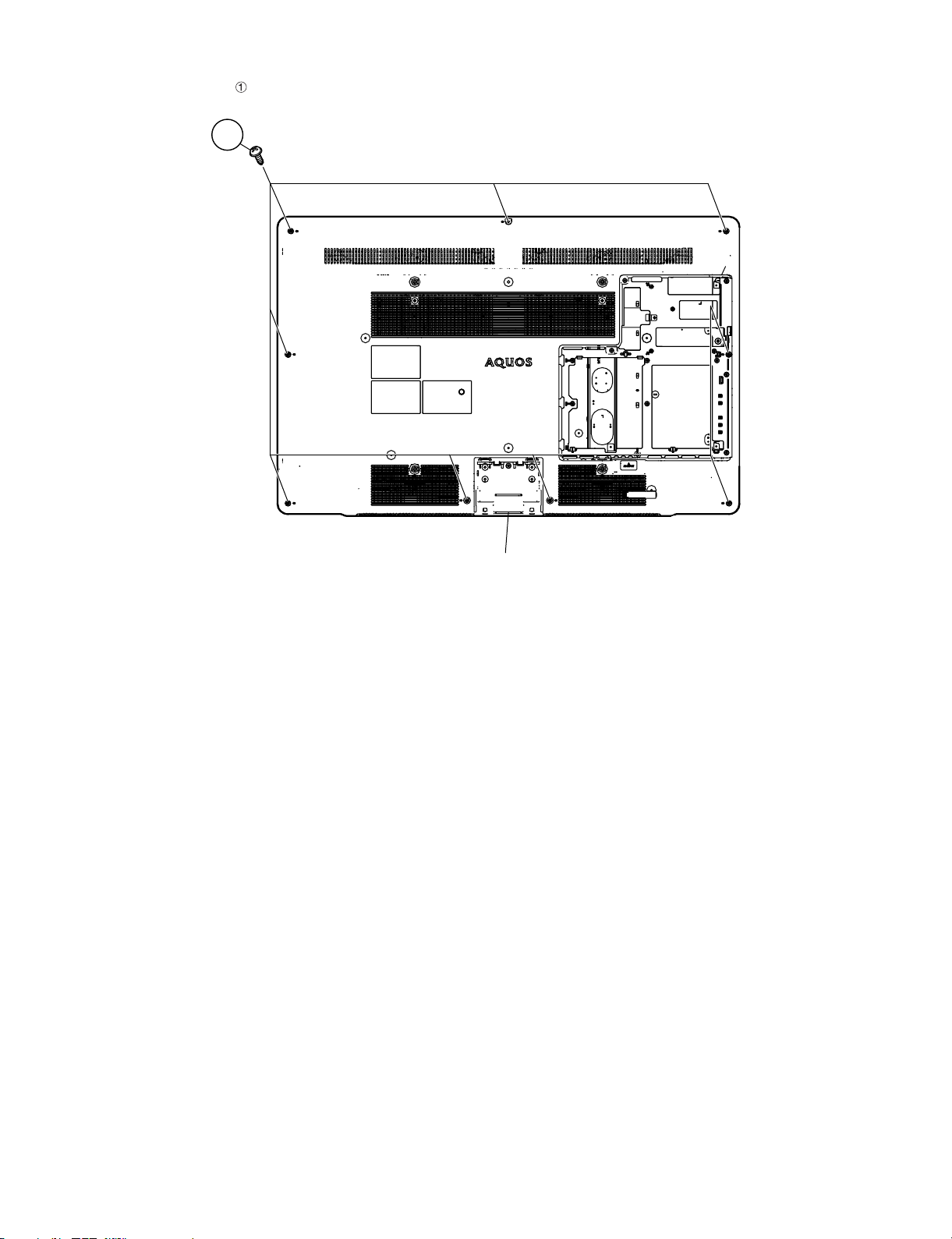
3. Removing of the Rear Cabinet
1. Remove the 9 lock screws and detach the Rear Cabinet.
1
LC-40L550/650M
Rear Cabinet
4 – 3
Page 14
LC-40L550/650M
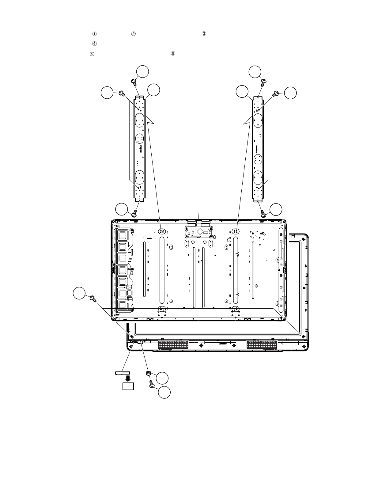
4. Removing of the Speaker-LR, VESA Angle, Earth Angle
1. Disconnect SP connectors . Remove the 2 lock screws and detach the Speaker-LR.
2. Disconnect the connectors from the LCD Control Unit , INVERTER Unit .
3. Remove the 8 lock screws and detach the VESA Angle .
4. Remove the 6 lock screws and detach the Fixing Metal , Earth Angle .
5. Remove the 2 lock screws and detach the Side Earth Angle and Top Earth Angle .
INVERTER
4
Unit
5
5
VESA Angle
6
VESA Angle
3
LCD Control Unit
6
10
PI
LW
Top Earth Angle
12
Side Earth Angle
11
10
Speaker-L
Speaker-R
1
Fixing Metal
1
SP
2
7
VESA Angle
5
8
Earth Angle
6
7
9
6
VESA Angle
SP
2
5
4 – 4
Page 15
5. Removing of the Center Angle, R/C, LED Unit, LCD Panel Module
1. Remove the 4 lock screws , 4 lock screws and detach the Center Angle .
2. Remove the 2 lock screws and detach the LCD Panel Module.
3. Remove the 1 lock screw and detach the Power Decoration and R/C, LED Unit.
LC-40L550/650M
1
2
1
3
Center Angle
LCD Panel Module
Center Angle
1
3
2
1
4
R/C, LED Unit
RA
Power Decoration
6
5
4 – 5
Page 16

LC-40L550/650M
- MEMO -
4 – 6
Page 17

LC40L550M
CHAPTER 5. OVERALL WIRING/BLOCK DIAGRAM
[1] OVERALL WIRING DIAGRAM
LC-40L550/650M
ServiceManual
(40L650M)
(40L550M)
(40L650M)
5 – 1
Page 18

LC-40L550/650M
㪀
㪀
㪀
㪀
㪀
㪀
㪀
㪀
㪀
㪀
㪀
㩿
㩿
㪀
㩿
㪀
㩿
㩿
㪀
㩿
㪀
㩿
㩿
㪀
㪶
㪶
[2] SYSTEM BLOCK DIAGRAM (LC-40L550M)
㪜㪜㪧㪩㪦㪤
㪠㪚㪌㪇㪏
㪭㪟㪠㪪㪉㪋㪚㪪㪇㪉㪡㪄㪈㪰
㪧㪚㩷㩷㪛㪪㪬㪙㩷㪈㪌㫇㫀㫅
㪪㪚㪌㪇㪉
㪨㪪㪦㪚㪥㪘㪎㪈㪍㪮㪡㪱㪱
㪠㪥㪧㪬㪫㪎
㪠㪉㪚㩷㪘㪛㪛㪩㪜㪪㪪䋺㪚㪍䇮
㪫㪬㪥㪜㪩
㪫㪬㪈㪈㪇㪊
㪩㪫㪬㪥㪨㪘㪇㪍㪋㪮㪡㪨㪱
㪠㪥㪧㪬㪫㪋
㪚㪭㪙㪪㩷㪠㪥
㪡㪌㪇㪎
㪨㪡㪘㪢㪞㪘㪈㪍㪈㪮㪡㪨㪱
㪠㪥㪧㪬㪫㪋
㪪㪰㪆㪚㩷㪠㪥
㪡㪌㪈㪈
㪨㪪㪦㪚㪛㪘㪇㪊㪌㪮㪡㪱㪱
㪠㪥㪧㪬㪫㪌
㪚㪭㪙㪪㩷㪠㪥
㪡㪌㪇㪏
㪨㪡㪘㪢㪞㪘㪈㪍㪈㪮㪡㪨㪱
㪠㪥㪧㪬㪫㪍
㪚㪦㪤㪧㪦㪥㪜㪥㪫㩷㪈㩷㪠㪥
㪡㪌㪇㪐
㪨㪡㪘㪢㪞㪘㪈㪊㪈㪮㪡㪱㪱
㪠㪥㪧㪬㪫㪍
㪠㪥㪧㪬㪫㪈㩷㪘㪬㪛㪠㪦㩷㪠㪥
㪡㪌㪇㪊
㪨㪡㪘㪢㪝㪘㪇㪍㪏㪮㪡㪨㪱
㪠㪥㪧㪬㪫㪈㪆㪠㪥㪧㪬㪫㪎
㪟㪛㪤㪠㪆㪧㪚㩷㪣㪆㪩
㪡㪌㪇㪍
㪨㪡㪘㪢㪡㪘㪇㪉㪋㪮㪡㪱㪱
㪤㪦㪥㪠㪫㪦㪩㩷㪘㪬㪛㪠㪦㩷㪦㪬㪫
㪡㪌㪇㪉
㪨㪡㪘㪢㪝㪘㪇㪍㪏㪮㪡㪨㪱
㪟㪧㩷㪦㪬㪫
㪡㪌㪇㪌
㪨㪡㪘㪢㪡㪇㪈㪇㪈㪪㪜㪱㪱
㪛㪠㪞㪠㪫㪘㪣㩷㪘㪬㪛㪠㪦㩷㪦㪬㪫
㪛㪌㪈㪍
㪭㪟㪧㪞㪧㪝㪪㪭㪌㪈㪭㪄㪈
㪮㪧㪶㪚㪦㪥㪫
㪧㪚㩿㪩㪞㪙
㪟㪛
㪭㪛
㪫㪬㪥㪜㪩㪶㪚㪭㪙㪪
㫋㫌㫅㪼㫉㩷㪠㪉㪚
㪪㪶㪠㪝
㪠㪥㪧㪬㪫㪋
㪠㪥㪧㪬㪫㪋㩷㪣㪆㪩
㪠㪥㪧㪬㪫㪋㪶㪪㪰㪆㪪
㪠㪥㪧㪬㪫㪌
㪠㪥㪧㪬㪫㪌㩷㪣㪆㪩
㪠㪥㪧㪬㪫㪍㪶㪰㪃㪧㪹㪃㪧
㪠㪥㪧㪬㪫㪍㩷㪣㪆㪩
㪤㪘㪠㪥
㪚㪭㪙㪪
㪚㪭㪙㪪
㪪㪠㪝㩷㪘㪤㪧㩷㪚㫀㫉㪺㫌㫀㫋
㪤㪦㪥㪠㪫㪦㪩㩷㩷㪘㪬㪛㪠㪦㩷㪘㪤㪧
㪠㪚㪉㪎㪇㪊
㪭㪟㪠㪥㪡㪤㪋㪌㪍㪌㪭㪄㪈㪰
㪟㪧㩷㪘㪤㪧
㪚㫀㫉㪺㫌㫀㫋
㪠㪥㪧㪬㪫㪋㪶㪚㪭㪙㪪
㵘
㪠㪥㪧㪬㪫㪋㪶㪪
㪠㪥㪧㪬㪫㪌㪶㪚㪭㪙㪪
㪠㪥㪧㪬㪫㪎㪶㪚㪦㪤㪧
㪟㪧㩷㪻㪼㫋㪼㪺㫋
㪠㪥㪧㪬㪫㪈
㪧㪚㩷㪛㪛㪚
㪚㪭㪙㪪㪈
㪪㪠㪝㩷㪠㪥
㪚㪭㪙㪪㪉
㪣㪆㪩㩷㪠㪥㪇
㪰㪆㪚㪈
㪚㪭㪙㪪㪊
㪣㪆㪩㩷㪠㪥㪈
㪚㪦㪤㪧㪈
㪣㪆㪩㩷㪠㪥㪊
㪣㪆㪩㩷㪠㪥㪌
㪤㪦㪥㪠㪫㪦㪩㩷㪦㪬㪫
㪟㪧㩷㪦㪬㪫
㪪㪧㪛㪠㪝㩷㪦㪬㪫
㪟㪛㪤㪠㩷㪈
㪪㪚㪈㪌㪇㪈
㪨㪪㪦㪚㪱㪘㪈㪎㪊㪮㪡㪨㪱㪰
㪋
㪉
㪺㫃㫂
㪻㪸㫋㪸
㪟㪛㪤㪠㪊
㪠㪉㪚
㪟㪧㪞㩷㪈㪆㪧㪦㪮㪌㪭㩷㪈
㪟㪛㪤㪠㩷㪠㪥㪈
㪟㪛㪤㪠㩷㪛㪛㪚㪈
㪟㪛㪤㪠㩷㪉
㪠㪥㪧㪬㪫㪉 㪠㪥㪧㪬㪫㪊
㪪㪚㪈㪌㪇㪊
㪨㪪㪦㪚㪱㪘㪈㪎㪊㪮㪡㪨㪱㪰
㪋
㪉
㪺㫃㫂
㪠㪚㪈㪌㪇㪊
㪻㪸㫋㪸
㪟㪧㪞㩷㪉㪆㪧㪦㪮㪌㪭㩷㪉
㪟㪛㪤㪠㩷㪠㪥㪉
㪟㪛㪤㪠㩷㪛㪛㪚㪉
㪚㪜㪚
㪜㪜㪧㪩㪦㪤
㪭㪟㪠㪪㪉㪋㪚㪪㪇㪉㪡㪄㪈㪰
㪚㪜㪚
㪠㪉㪚㩿㪟㪛㪤㪠㪉㪀
㪭㪟㪠㪪㪉㪋㪚㪪㪇㪉㪡㪄㪈㪰
㪜㪜㪧㪩㪦㪤
㪠㪚㪈㪌㪇㪌
㪟㪛㪤㪠㩷㪊
㪪㪚㪈㪌㪇㪉
㪨㪪㪦㪚㪱㪘㪈㪋㪐㪮㪡㪨㪱㪰
㪋
㪉
㪺㫃㫂
㪻㪸㫋㪸
㪟㪛㪤㪠㪈
㪠㪉㪚
㪟㪧㪞㩷㪊㪆㪧㪦㪮㪌㪭㩷㪊
㪟㪛㪤㪠㩷㪛㪛㪚㪊
㪚㪜㪚
㪜㪜㪧㪩㪦㪤
㪠㪚㪈㪌㪇㪋
㪭㪟㪠㪪㪉㪋㪚㪪㪇㪉㪡㪄㪈㪰
㪚㪜㪚
㪚㪜㪚㩷㪠㪥㪟㪛㪤㪠㩷㪠㪥㪊
㪢㪜㪰㪈
㪤㪘㪠㪥㩷㪪㪮
㪠㪚㪊㪊㪇㪊
㪤㫌㫃㫋㫀㪤㪼㪻㫀㪸
㪩㪟㪄㪠㪯㪛㪈㪎㪐㪮㪡㪨㪱㪨
㪬㪘㪩㪫 㪠㪉㪪㩷㪠㪆㪝
㪩㪪㪉㪊㪉㪚㩷㪙㫌㪽㪽㪼㫉
㪠㪚㪌㪇㪈
㵘㵘㵘
㪭㪟㪠㪤㪊㪉㪉㪈㪜㪠㪧㪄㪈㪰
㪩㪪㪄㪉㪊㪉㪚
㪪㪚㪌㪇㪈
㪨㪪㪦㪚㪥㪘㪎㪈㪌㪮㪡㪱㪱
㪨㪪㪦㪚㪱㪘㪉㪇㪌㪮㪡㪨㪱
㵘㵘㵘㵘㵘㵘㵘
㪛㪧
㪬㪪㪙
㪡㪌㪇㪈
㪟㪆㪮㩷㪩㪜㪪㪜㪫
㪩㪜㪪㪜㪫
㪠㪚㪊㪊㪇㪉
㪭㪟㪠㪧㪪㪫㪏㪋㪉㪐㪬㪄
㪛㪛㪩㪉㩿㪌㪈㪉㪤㪹㪀
㪠㪚㪊㪌㪇㪈
㪩㪟㪄
㪠㪯㪚㪌㪈㪉㪮㪡㪨㪱㪨
㪛㪩㪘㪤㩷㪠㪝㪬㪪㪙㩷㪠㪝
㪛㪛㪩㪉㩿㪌㪈㪉㪤㪹㪀
㪠㪚㪊㪌㪇㪉
㪩㪟㪄㪠㪯㪚㪌㪈㪉㪮㪡㪨㪱㪨
㪣㪜㪛
㪣㪜㪛
㪛㪈㪇㪉㪆㪈㪇㪊
㪩㪘㩿㪎㪀
㪧㪊㪊㪇㪈
㪨㪧㪣㪞㪥㪘㪊㪉㪎㪮㪡㪱㪱㪰
㪠㪚㪈㪇㪈
㪠㪩㩷㪩㪼㪺㫀㪼㫍㪼㫉
㪦㪧㪚
㪩㪤㪚㪈㪇㪈
㪢㪜㪰
㪤㪘㪠㪥㩷㪪㪮
㪢㪜㪰㪈
㪢㪜㪰㪉
㪠㪩㪜㪤
䌇㩷㪣㪜㪛
㩷
㪣㪭㪛㪪㩿㪈㪇㪹㫀㫋㪀
㪣㪭㪛㪪㩿㪈㪇㪹㫀㫋㪀
㪪㪧㪠㩷㪠㪆㪝
㪪㪧㪠
㪪㪧㪠㩷㪝㪣㪘㪪㪟
㪠㪚㪏㪋㪇㪋
㪩㪟㪄㪠㪯㪛㪉㪇㪇㪮㪡㪨㪱㪰
㪏㪤㪙
㵘㵘㵘㵘
㪩㩷㪣㪜㪛
㪪㪧㪠㩷㪝㪣㪘㪪㪟
㪮㪩㪠㪫㪜
㪚㪟㪜㪢㪜㪩㩷㪣㪘㪥㪛
㪜㪩㪩㪦㪩
㪦㪝㪣
㪧㪥㪣㩷㪪㪫㪙
㪘㪚㪶㪛㪜㪫
㪧㪪㪶㪦㪥
㪻㪸㫋㪸㩷㪘㩿㪈㪇
㪺㫃㫂㩷㪘㩿㪉
㪻㪸㫋㪸㩷㪙㩿㪈㪇
㪺㫃㫂㩷㪙㩿㪉
㪺㫆㫅㫋㫉㫆㫃㩿㪉
㪭㪚㪦㪤㩷㪮㪧
㪫㪄㪚㪦㪥㩷㪠㪉㪚
㪯㪠㪥㪆㪯㪦㪬㪫
㪠㪉㪚
㪠㪉㪚
㪨㪚㪥㪚㪮㪘㪉㪌㪈㪮㪡㪱㪱㪰
㪛㪚㪆㪛㪚
㪚㫀㫉㪺㫌㫀㫋
㪨㪚㪥㪚㪮㪘㪍㪎㪈㪮㪡㪨㪱㪰
㪯㪫㪘㪣㩿㪈㪉㪤㪟㫑㪀
㪯㪊㪊㪇㪈
㪩㪚㪩㪪㪚㪘㪉㪈㪌㪮㪡㪨㪱
㪰
㪠㪉㪚㩷㪘㪛㪛㪩㪜㪪㪪䋺
㪜㪜㪧㪩㪦㪤㩿㪟㪛㪚㪧㪀
㪠㪚㪏㪋㪇㪊
㪩㪟㪄
㪠㪯㪛㪈㪈㪇㪮㪡㪨㪱㪰
㪠㪉㪚㩷㪘㪛㪛㪩㪜㪪㪪䋺
㪜㪜㪧㪩㪦㪤㩿㪛㪘㪫㪘㪀
㪠㪚㪏㪋㪇㪉
㪭㪟㪠㪩㪉㪋㪈㪉㪏㪘㪪㪄㪈㪰
㪌㪈㪉㫂㪙㫐㫋㪼
㪎㪅㪌㹢㪈㪊㪅㪌㪭
㪙㩷㫋㫆㩷㪙
㪪㪚㪐㪍㪇㪈
㪉㪊㫇㫀㫅
㪣㪮
㪪㪚㪉㪍㪇㪈
㪋㪈㫇㫀㫅
㪫㪜㪤㪧㩷㪪㪜㪥㪪㪦㪩
㪫㪟㪊㪊㪇㪈
㪩㪟㪄㪟㪯㪘㪇㪋㪎㪮㪡㪨㪱㪰
㪢㪜㪰㪉
㪘㪛㪚㩿㪉㪀㪘㪛㪚㩿㪈㪀
㪘㪛㪚㩿㪊㪀
㪭㪟㪠㪰㪛㪘㪈㪍㪋㪨㪱㪄㪈㪰
㪪㪧㪶㪣
㪨㪧㪣㪞㪥㪘㪈㪍㪇㪮㪡㪱㪱㪰
㪪㪧㪶㪣
㪪㪧㪶㪣
㪏㱅
㪠㪉㪪
㪘㪬㪛㪠㪦㩷㪘㪤㪧
㪪㪧
㪠㪚㪉㪎㪇㪋
㪧㪉㪎㪇㪈
㪪㪧
㪠㪉㪚㩷㪘㪛㪛㪩㪜㪪㪪䋺㪊㪏
㪦㪧㪚
㪘㪛㪚㩿㪋㪀 㪠㪩㩷㪠㫅㫋㪼㫉㪽㪸㪺㪼
㪠㪉㪚
㪪㪧㪶㪩
㪪㪧㪶㪩
㪪㪧㪶㪩
㪏㱅
㪧㪦㪮㩷㪪㪮
㪪㪈㪎㪎
㪚㪦㪥㪫㪩㪦㪣㩷㪪㪮
㪪㪈㪎㪈㪄㪪㪈㪎㪌
㪈㪉㪭
㪻㪸㫋㪸㩷㪘㩿㪈㪇
㪺㫃㫂㩷㪘㩿㪉
㪻㪸㫋㪸㩷㪙㩿㪈㪇
㪺㫃㫂㩷㪙㩿㪉
㪺㫆㫅㫋㫉㫆㫃㩿㪉
㪧㪦㪮㪜㪩
㪬㪥㪠㪫
㪈㪉㪭
㪫㪄㪚㪦㪥
㪫㪄㪚㪦㪥
㪠㪛㪫
㪠㪛㪫
㩿㪌㪇㪟㫑㪀
㩿㪌㪇㪟㫑㪀
㪌㪇㪟㫑
㪠㪥㪭
㪪㪟㪘㪩㪧
㩷㪣㪚㪛㩷㪧㪘㪥㪜㪣
㪋㪇㩹
㪌㪇㪟㫑
㩷
5 – 2
Page 19

[3] SYSTEM BLOCK DIAGRAM (LC-40L650M)
㪀
㪀
㪀
㪀
㪀
㪀
㩿
㩿
㪀
㩿
㪀
㩿
㩿
㪀
㩿
㪀
㩿
㩿
㪀
㪶
㪶
㩿㪈㪇㪀
㪀
㪀
㪀
㪀
LC-40L550/650M
㪜㪜㪧㪩㪦㪤
㪠㪚㪌㪇㪏
㪭㪟㪠㪪㪉㪋㪚㪪㪇㪉㪡㪄㪈㪰
㪧㪚㩷㩷㪛㪪㪬㪙㩷㪈㪌㫇㫀㫅
㪪㪚㪌㪇㪉
㪨㪪㪦㪚㪥㪘㪎㪈㪍㪮㪡㪱㪱
㪠㪥㪧㪬㪫㪎
㪠㪉㪚㩷㪘㪛㪛㪩㪜㪪㪪䋺㪚㪍䇮
㪫㪬㪥㪜㪩
㪫㪬㪈㪈㪇㪊
㪩㪫㪬㪥㪨㪘㪇㪍㪋㪮㪡㪨㪱
㪠㪥㪧㪬㪫㪋
㪚㪭㪙㪪㩷㪠㪥
㪡㪌㪇㪎
㪨㪡㪘㪢㪞㪘㪈㪍㪈㪮㪡㪨㪱
㪠㪥㪧㪬㪫㪋
㪪㪰㪆㪚㩷㪠㪥
㪡㪌㪈㪈
㪨㪪㪦㪚㪛㪘㪇㪊㪌㪮㪡㪱㪱
㪠㪥㪧㪬㪫㪌
㪚㪭㪙㪪㩷㪠㪥
㪡㪌㪇㪏
㪨㪡㪘㪢㪞㪘㪈㪍㪈㪮㪡㪨㪱
㪠㪥㪧㪬㪫㪍
㪚㪦㪤㪧㪦㪥㪜㪥㪫㩷㪈㩷㪠㪥
㪡㪌㪇㪐
㪨㪡㪘㪢㪞㪘㪈㪊㪈㪮㪡㪱㪱
㪠㪥㪧㪬㪫㪍
㪠㪥㪧㪬㪫㪈㩷㪘㪬㪛㪠㪦㩷㪠㪥
㪡㪌㪇㪊
㪨㪡㪘㪢㪝㪘㪇㪍㪏㪮㪡㪨㪱
㪠㪥㪧㪬㪫㪈㪆㪠㪥㪧㪬㪫㪎
㪟㪛㪤㪠㪆㪧㪚㩷㪣㪆㪩
㪡㪌㪇㪍
㪨㪡㪘㪢㪡㪘㪇㪉㪋㪮㪡㪱㪱
㪤㪦㪥㪠㪫㪦㪩㩷㪘㪬㪛㪠㪦㩷㪦㪬㪫
㪡㪌㪇㪉
㪨㪡㪘㪢㪝㪘㪇㪍㪏㪮㪡㪨㪱
㪟㪧㩷㪦㪬㪫
㪡㪌㪇㪌
㪨㪡㪘㪢㪡㪇㪈㪇㪈㪪㪜㪱㪱
㪛㪠㪞㪠㪫㪘㪣㩷㪘㪬㪛㪠㪦㩷㪦㪬㪫
㪛㪌㪈㪍
㪭㪟㪧㪞㪧㪝㪪㪭㪌㪈㪭㪄㪈
㪮㪧㪶㪚㪦㪥㪫
㪧㪚㩿㪩㪞㪙
㪟㪛
㪭㪛
㪫㪬㪥㪜㪩㪶㪚㪭㪙㪪
㫋㫌㫅㪼㫉㩷㪠㪉㪚
㪪㪶㪠㪝
㪠㪥㪧㪬㪫㪋
㪠㪥㪧㪬㪫㪋㩷㪣㪆㪩
㪠㪥㪧㪬㪫㪋㪶㪪㪰㪆㪪
㪠㪥㪧㪬㪫㪌
㪠㪥㪧㪬㪫㪌㩷㪣㪆㪩
㪠㪥㪧㪬㪫㪍㪶㪰㪃㪧㪹㪃㪧
㪠㪥㪧㪬㪫㪍㩷㪣㪆㪩
㪤㪘㪠㪥
㪚㪭㪙㪪
㪚㪭㪙㪪
㪪㪠㪝㩷㪘㪤㪧㩷㪚㫀㫉㪺㫌㫀㫋
㪤㪦㪥㪠㪫㪦㪩㩷㩷㪘㪬㪛㪠㪦㩷㪘㪤㪧
㪠㪚㪉㪎㪇㪊
㪭㪟㪠㪥㪡㪤㪋㪌㪍㪌㪭㪄㪈㪰
㪟㪧㩷㪘㪤㪧
㪚㫀㫉㪺㫌㫀㫋
㪠㪥㪧㪬㪫㪋㪶㪚㪭㪙㪪
㵘
㪠㪥㪧㪬㪫㪋㪶㪪
㪠㪥㪧㪬㪫㪌㪶㪚㪭㪙㪪
㪠㪥㪧㪬㪫㪎㪶㪚㪦㪤㪧
㪟㪧㩷㪻㪼㫋㪼㪺㫋
㪠㪥㪧㪬㪫㪈
㪧㪚㩷㪛㪛㪚
㪚㪭㪙㪪㪈
㪪㪠㪝㩷㪠㪥
㪚㪭㪙㪪㪉
㪣㪆㪩㩷㪠㪥㪇
㪰㪆㪚㪈
㪚㪭㪙㪪㪊
㪣㪆㪩㩷㪠㪥㪈
㪚㪦㪤㪧㪈
㪣㪆㪩㩷㪠㪥㪊
㪣㪆㪩㩷㪠㪥㪌
㪤㪦㪥㪠㪫㪦㪩㩷㪦㪬㪫
㪟㪧㩷㪦㪬㪫
㪪㪧㪛㪠㪝㩷㪦㪬㪫
㪟㪛㪤㪠㩷㪈
㪪㪚㪈㪌㪇㪈
㪨㪪㪦㪚㪱㪘㪈㪎㪊㪮㪡㪨㪱㪰
㪋
㪉
㪺㫃㫂
㪻㪸㫋㪸
㪟㪛㪤㪠㪊
㪠㪉㪚
㪟㪧㪞㩷㪈㪆㪧㪦㪮㪌㪭㩷㪈
㪟㪛㪤㪠㩷㪠㪥㪈
㪟㪛㪤㪠㩷㪛㪛㪚㪈
㪟㪛㪤㪠㩷㪉
㪠㪥㪧㪬㪫㪉 㪠㪥㪧㪬㪫㪊
㪪㪚㪈㪌㪇㪊
㪨㪪㪦㪚㪱㪘㪈㪎㪊㪮㪡㪨㪱㪰
㪋
㪉
㪺㫃㫂
㪠㪚㪈㪌㪇㪊
㪻㪸㫋㪸
㪟㪧㪞㩷㪉㪆㪧㪦㪮㪌㪭㩷㪉
㪟㪛㪤㪠㩷㪠㪥㪉
㪟㪛㪤㪠㩷㪛㪛㪚㪉
㪚㪜㪚
㪜㪜㪧㪩㪦㪤
㪭㪟㪠㪪㪉㪋㪚㪪㪇㪉㪡㪄㪈㪰
㪚㪜㪚
㪠㪉㪚㩿㪟㪛㪤㪠㪉㪀
㪭㪟㪠㪪㪉㪋㪚㪪㪇㪉㪡㪄㪈㪰
㪜㪜㪧㪩㪦㪤
㪠㪚㪈㪌㪇㪌
㪟㪛㪤㪠㩷㪊
㪪㪚㪈㪌㪇㪉
㪨㪪㪦㪚㪱㪘㪈㪋㪐㪮㪡㪨㪱㪰
㪋
㪉
㪺㫃㫂
㪻㪸㫋㪸
㪟㪛㪤㪠㪈
㪠㪉㪚
㪟㪧㪞㩷㪊㪆㪧㪦㪮㪌㪭㩷㪊
㪟㪛㪤㪠㩷㪛㪛㪚㪊
㪚㪜㪚
㪜㪜㪧㪩㪦㪤
㪠㪚㪈㪌㪇㪋
㪭㪟㪠㪪㪉㪋㪚㪪㪇㪉㪡㪄㪈㪰
㪚㪜㪚
㪚㪜㪚㩷㪠㪥㪟㪛㪤㪠㩷㪠㪥㪊
㪢㪜㪰㪈
㪤㪘㪠㪥㩷㪪㪮
㪠㪚㪊㪊㪇㪊
㪤㫌㫃㫋㫀㪤㪼㪻㫀㪸
㪩㪟㪄㪠㪯㪛㪈㪎㪐㪮㪡㪨㪱㪨
㪬㪘㪩㪫 㪠㪉㪪㩷㪠㪆㪝
㪩㪪㪉㪊㪉㪚㩷㪙㫌㪽㪽㪼㫉
㪠㪚㪌㪇㪈
㵘㵘㵘
㪭㪟㪠㪤㪊㪉㪉㪈㪜㪠㪧㪄㪈㪰
㪩㪪㪄㪉㪊㪉㪚
㪪㪚㪌㪇㪈
㪨㪪㪦㪚㪥㪘㪎㪈㪌㪮㪡㪱㪱
㪨㪪㪦㪚㪱㪘㪉㪇㪌㪮㪡㪨㪱
㵘㵘㵘㵘㵘㵘㵘
㪛㪧
㪬㪪㪙
㪡㪌㪇㪈
㪟㪆㪮㩷㪩㪜㪪㪜㪫
㪩㪜㪪㪜㪫
㪠㪚㪊㪊㪇㪉
㪭㪟㪠㪧㪪㪫㪏㪋㪉㪐㪬㪄
㪛㪛㪩㪉㩿㪌㪈㪉㪤㪹㪀
㪠㪚㪊㪌㪇㪈
㪩㪟㪄
㪠㪯㪚㪌㪈㪉㪮㪡㪨㪱㪨
㪛㪩㪘㪤㩷㪠㪝㪬㪪㪙㩷㪠㪝
㪛㪛㪩㪉㩿㪌㪈㪉㪤㪹㪀
㪠㪚㪊㪌㪇㪉
㪩㪟㪄㪠㪯㪚㪌㪈㪉㪮㪡㪨㪱㪨
㪣㪜㪛
㪣㪜㪛
㪛㪈㪇㪉㪆㪈㪇㪊
㪩㪘㩿㪎㪀
㪧㪊㪊㪇㪈
㪨㪧㪣㪞㪥㪘㪊㪉㪎㪮㪡㪱㪱㪰
㪠㪚㪈㪇㪈
㪠㪩㩷㪩㪼㪺㫀㪼㫍㪼㫉
㪦㪧㪚
㪩㪤㪚㪈㪇㪈
㪢㪜㪰
㪤㪘㪠㪥㩷㪪㪮
㪭㪚㪦㪤㩷㪮㪧
㪭㪚㪦㪤㩷㪠㪉㪚
㪢㪜㪰㪈
㪢㪜㪰㪉
㪠㪩㪜㪤
䌇㩷㪣㪜㪛
㩷
㪣㪭㪛㪪㩿㪈㪇㪹㫀㫋㪀
㪣㪭㪛㪪㩿㪈㪇㪹㫀㫋㪀
㪪㪧㪠㩷㪠㪆㪝
㪪㪧㪠
㪪㪧㪠㩷㪝㪣㪘㪪㪟
㪠㪚㪏㪋㪇㪋
㪩㪟㪄㪠㪯㪛㪉㪇㪇㪮㪡㪨㪱㪰
㪏㪤㪙
㵘㵘㵘㵘
㪩㩷㪣㪜㪛
㪪㪧㪠㩷㪝㪣㪘㪪㪟
㪮㪩㪠㪫㪜
㪚㪟㪜㪢㪜㪩㩷㪣㪘㪥㪛
㪜㪩㪩㪦㪩
㪦㪝㪣
㪧㪥㪣㩷㪪㪫㪙
㪘㪚㪶㪛㪜㪫
㪧㪪㪶㪦㪥
㪻㪸㫋㪸㩷㪘㩿㪈㪇
㪺㫃㫂㩷㪘㩿㪉
㪻㪸㫋㪸㩷㪙㩿㪈㪇
㪺㫃㫂㩷㪙㩿㪉
㪺㫆㫅㫋㫉㫆㫃㩿㪉
㪭㪚㪦㪤㩷㪮㪧
㪫㪄㪚㪦㪥㩷㪠㪉㪚
㪯㪠㪥㪆㪯㪦㪬㪫
㪠㪉㪚
㪠㪉㪚
㪨㪚㪥㪚㪮㪘㪉㪌㪈㪮㪡㪱㪱㪰
㪛㪚㪆㪛㪚
㪚㫀㫉㪺㫌㫀㫋
㪨㪚㪥㪚㪮㪘㪍㪎㪈㪮㪡㪨㪱㪰
㪯㪫㪘㪣㩿㪈㪉㪤㪟㫑㪀
㪯㪊㪊㪇㪈
㪩㪚㪩㪪㪚㪘㪉㪈㪌㪮㪡㪨㪱
㪰
㪠㪉㪚㩷㪘㪛㪛㪩㪜㪪㪪䋺
㪜㪜㪧㪩㪦㪤㩿㪟㪛㪚㪧㪀
㪠㪚㪏㪋㪇㪊
㪩㪟㪄
㪠㪯㪛㪈㪈㪇㪮㪡㪨㪱㪰
㪠㪉㪚㩷㪘㪛㪛㪩㪜㪪㪪䋺
㪜㪜㪧㪩㪦㪤㩿㪛㪘㪫㪘㪀
㪠㪚㪏㪋㪇㪉
㪭㪟㪠㪩㪉㪋㪈㪉㪏㪘㪪㪄㪈㪰
㪌㪈㪉㫂㪙㫐㫋㪼
㪎㪅㪌㹢㪈㪊㪅㪌㪭
㪙㩷㫋㫆㩷㪙
㪪㪚㪐㪍㪇㪈
㪉㪊㫇㫀㫅
㪣㪮
㪪㪚㪉㪍㪇㪈
㪋㪈㫇㫀㫅
㪫㪜㪤㪧㩷㪪㪜㪥㪪㪦㪩
㪫㪟㪊㪊㪇㪈
㪩㪟㪄㪟㪯㪘㪇㪋㪎㪮㪡㪨㪱㪰
㪢㪜㪰㪉
㪘㪛㪚㩿㪉㪀㪘㪛㪚㩿㪈㪀
㪘㪛㪚㩿㪊㪀
㪭㪟㪠㪰㪛㪘㪈㪍㪋㪨㪱㪄㪈㪰
㪪㪧㪶㪣
㪨㪧㪣㪞㪥㪘㪈㪍㪇㪮㪡㪱㪱㪰
㪪㪧㪶㪣
㪪㪧㪶㪣
㪏㱅
㪠㪉㪪
㪘㪬㪛㪠㪦㩷㪘㪤㪧
㪪㪧
㪠㪚㪉㪎㪇㪋
㪧㪉㪎㪇㪈
㪪㪧
㪠㪉㪚㩷㪘㪛㪛㪩㪜㪪㪪䋺㪊㪏
㪦㪧㪚
㪘㪛㪚㩿㪋㪀 㪠㪩㩷㪠㫅㫋㪼㫉㪽㪸㪺㪼
㪠㪉㪚
㪪㪧㪶㪩
㪪㪧㪶㪩
㪪㪧㪶㪩
㪏㱅
㪧㪦㪮㩷㪪㪮
㪪㪈㪎㪎
㪚㪦㪥㪫㪩㪦㪣㩷㪪㪮
㪪㪈㪎㪈㪄㪪㪈㪎㪌
㪈㪉㪭
㪻㪸㫋㪸㩷㪘
㪺㫃㫂㩷㪘㩿㪉
㪻㪸㫋㪸㩷㪙㩿㪈㪇
㪺㫃㫂㩷㪙㩿㪉
㪺㫆㫅㫋㫉㫆㫃㩿㪐
㪭㪚㪦㪤㩷㪮㪧
㪫㪄㪚㪦㪥㩷㪠㪉㪚
㪧㪦㪮㪜㪩
㪬㪥㪠㪫
㪈㪉㪭
㪫㪄㪚㪦㪥
㪧㫃㪸㫀㪺㪼
㩿㪈㪇㪇㪟㫑㪀
㪈㪇㪇㪟㫑
㪠㪥㪭
㪪㪟㪘㪩㪧
㪣㪚㪛㩷㪧㪘㪥㪜㪣
㪋㪇㩹
㪈㪇㪇㪟㫑
㩷
5 – 3
Page 20

LC-40L550/650M
LC40L550M
CHAPTER 6. SCHEMATIC DIAGRAM
[1] DESCRIPTION OF SCHEMATIC DIAGRAM
1. VOLTAGE MEASUREMENT CONDITION:
1) The voltages at test points are measured on exclusive AC adaptor and the stable supply voltage of AC 110-240V. Signals are fed by a color bar signal generator for servicing purpose and the above voltages are measured with a 20k ohm/V tester.
2. INDICATION OF RESISTOR & CAPACITOR:
RESISTOR
1) The unit of resistance "Ω" is omitted.
(K=kΩ=1000Ω, M=MΩ).
2) All resistors are ± 5%, unless otherwise noted.
(K= ± 10%, F= ± 1%, D= ± 0.5%)
3) All resistors are 1/16W, unless otherwise noted.
CAPACITOR
1) Al l capacitors are µF, unless otherwise noted.
(P=pF=µµF).
2) All capacitors are 50V, unless otherwise noted.
CAUTION:
This circuit diagram is original one, therefore there may be a slight
difference from yours.
ServiceManual
SAFETY NOTES:
1) DISCONNECT THE AC PLUG FROM THE AC OUTLET
BEFORE REPLACING PARTS.
2) SEMICONDUCTOR HEAT SINKS SHOULD BE REGARDED AS
POTENTIAL SHOCK HAZARDS WHEN THE CHASSIS IS
OPERATING.
IMPORTANT SAFETY NOTICE:
PARTS MARKED WITH " " ( ) ARE IMPORTANT
FOR MAINTAINING THE SAFETY OF THE SET. BE SURE TO
REPLACE THESE PARTS WITH SPECIFIED ONES FOR MAINTAINING THE SAFETY AND PERFORMANCE OF THE SET.
6 – 1
Page 21

[2] MAIN Unit
•MAIN Unit-1/10
J
I
H
G
LC-40L550/650M
F
E
D
C
B
A
1
23
8
1097654
1311 191816151412 17
6 – 2
Page 22

LC-40L550/650M
•MAIN Unit-2/10
J
I
H
G
F
E
D
C
B
A
1
23
8
1097654
1311 191816151412 17
6 – 3
Page 23

•MAIN Unit-3/10
J
I
H
G
LC-40L550/650M
F
E
D
C
B
A
1
23
8
1097654
1311 191816151412 17
6 – 4
Page 24

LC-40L550/650M
• MAIN Unit-4/10 (LC-40L550M)
J
I
H
G
F
E
D
C
B
A
1
23
8
1097654
1311 191816151412 17
6 – 5
Page 25

• MAIN Unit-4/10 (LC-40L650M)
J
I
H
G
LC-40L550/650M
F
E
D
C
B
A
1
23
8
1097654
1311 191816151412 17
6 – 6
Page 26

LC-40L550/650M
•MAIN Unit-5/10
J
I
H
G
F
E
D
C
B
A
1
23
8
1097654
1311 191816151412 17
6 – 7
Page 27

• MAIN Unit-6/10 (*On this model, the MAIN Circuit Basic Diagram 7/10 is not applied.)
J
I
H
G
LC-40L550/650M
F
E
D
C
B
A
1
23
8
1097654
1311 191816151412 17
6 – 8
Page 28

LC-40L550/650M
• MAIN Unit-8/10 (LC-40L550M)
J
I
H
G
F
E
D
C
B
A
1
23
8
1097654
1311 191816151412 17
6 – 9
Page 29

• MAIN Unit-8/10 (LC-40L650M)
J
I
H
G
LC-40L550/650M
F
E
D
C
B
A
1
23
8
1097654
1311 191816151412 17
6 – 10
Page 30

LC-40L550/650M
•MAIN Unit-9/10
J
I
H
G
F
E
D
C
B
A
1
23
8
1097654
1311 191816151412 17
6 – 11
Page 31

• MAIN Unit-10/10 (LC-40L550M)
J
I
H
G
LC-40L550/650M
F
E
D
C
B
A
1
23
8
1097654
1311 191816151412 17
6 – 12
Page 32

LC-40L550/650M
• MAIN Unit-10/10 (LC-40L650M)
J
I
H
G
F
E
D
C
B
A
1
23
8
1097654
1311 191816151412 17
6 – 13
Page 33

PartsGuide
LC-40L550/650M
PARTS GUIDE
No. S80I8LC40L65M
LCD COLOUR TELEVISION
LC-40L550M
Note:
The reference numbers on the PWB
are arranged in alphabetical order.
[1] PRINTED WIRING BOARD
ASSEMBLIES
[2] LCD PANEL
[3] DKEYMF541FM06/FM08/
DUNTKF541FM16/FM18 (MAIN
Unit)
[4] DUNTKF573FM02 (R/C, LED Unit)
MODELS
CONTENTS
LC-40L650M
[5] CABINET AND MECHANICAL
PARTS
[6] SUPPLIED ACCESSORIES
[7] PACKING PARTS (NOT
REPLACEMENT ITEM)
[8] SERVICE JIGS (USE FOR
SERVICING)
Parts marked with " " are important for maintaining the safety of the set. Be sure to replace these
parts with specified ones for maintaining the safety and performance of the set.
This document has been published to be used
for after sales service only.
The contents are subject to change without notice.
Page 34

LC-40L550/650M
NO. PARTS CODE
PRICE
RANK
NEW
MARK
PART
DELIVERY
[1] PRINTED WIRING BOARD ASSEMBLIES
N DKEYMF541FM06 BY N V MAIN Unit (except Philippines) (40L550M)
N DUNTKF541FM16 BV N V MAIN Unit (for Philippines) (40L550M)
N DKEYMF541FM08 BY N V MAIN Unit (except Philippines) (40L650M)
N DUNTKF541FM18 BW N V MAIN Unit (for Philippines) (40L650M)
N DUNTKF573FM02 AU N V R/C, LED Unit
N RDENCA408WJQZ BP N V POWER Unit
[2] LCD PANEL
N R1LK400D3LWL0W DA N V LCD Panel Module Unit (40L550M)
N R1LK400D3GW20W DA N V LCD Panel Module Unit (40L650M)
[3] DKEYMF541FM06/FM08/DUNTKF541FM16/FM18 (MAIN Unit)
C501 RC-KZA616WJQZY AB J Capacitor
C502 VCKYCZ1EB103KY AA J Capacitor 0.01 25V Ceramic
C504 VCKYCY1HB104KY AA J Capacitor 0.1 50V Ceramic
C505 VCKYCY1HB104KY AA J Capacitor 0.1 50V Ceramic
C506 VCKYCY1HB104KY AA J Capacitor 0.1 50V Ceramic
C507 VCKYCY1HB104KY AA J Capacitor 0.1 50V Ceramic
C508 VCKYCY1HB561KY AA J Capacitor 560p 50V Ceramic
C509 RC-KZA237WJZZY AB J Capacitor
C510 RC-KZA067WJZZY AB J Capacitor
C511 VCKYCY1HB561KY AA J Capacitor 560p 50V Ceramic
C512 RC-KZA237WJZZY AB J Capacitor
C513 VCKYCZ1AB104KY AB J Capacitor 0.1 10V Ceramic
C514 VCCCCZ1HH560JY AB J Capacitor 56p 50V Ceramic
C515 VCCCCZ1HH102JY AA J Capacitor 1000p 50V Ceramic
C516 RC-KZA067WJZZY AB J Capacitor
C517 VCCCCZ1HH560JY AB J Capacitor 56p 50V Ceramic
C518 VCCCCZ1HH102JY AA J Capacitor 1000p 50V Ceramic
C523 RC-KZA237WJZZY AB J Capacitor
C525 VCKYCZ1EB103KY AA J Capacitor 0.01 25V Ceramic
C526 VCCCCZ1HH100DY AB J Capacitor 10p 50V Ceramic
C527 VCCCCZ1HH100DY AB J Capacitor 10p 50V Ceramic
C530 VCCCCZ1HH560JY AB J Capacitor 56p 50V Ceramic
C531 VCCCCZ1HH102JY AA J Capacitor 1000p 50V Ceramic
C532 VCCCCZ1HH560JY AB J Capacitor 56p 50V Ceramic
C533 VCCCCZ1HH102JY AA J Capacitor 1000p 50V Ceramic
C536 VCCCCZ1HH560JY AB J Capacitor 56p 50V Ceramic
C537 VCCCCZ1HH102JY AA J Capacitor 1000p 50V Ceramic
C538 VCCCCZ1HH560JY AB J Capacitor 56p 50V Ceramic
C539 VCCCCZ1HH102JY AA J Capacitor 1000p 50V Ceramic
C543 VCCCCZ1HH560JY AB J Capacitor 56p 50V Ceramic
C544 VCCCCZ1HH560JY AB J Capacitor 56p 50V Ceramic
C548 VCCCCZ1HH102JY AA J Capacitor 1000p 50V Ceramic
C553 VCCCCZ1HH102JY AA J Capacitor 1000p 50V Ceramic
C560 VCCCCZ1HH470JY AB J
C561 VCCCCZ1HH470JY AB J Capacitor 47p 50V Ceramic
C565 RC-KZA616WJQZY AB J Capacitor
C566 VCKYCZ1EB103KY AA J Capacitor 0.01 25V Ceramic
C1101 VCKYCZ1EF104ZY AA J Capacitor 0.1 25V Ceramic
C1102 RC-KZA616WJQZY AB J Capacitor
C1104 RC-KZA616WJQZY AB J Capacitor
C1105 RC-KZA616WJQZY AB J Capacitor
C1116 VCCCCZ1HH100DY AB J Capacitor 10p 50V Ceramic
C1137 VCCCCZ1HH220JY AB J Capacitor 22p 50V Ceramic
C1142 RC-KZA067WJZZY AB J Capacitor
C1143 RC-KZA067WJZZY AB J Capacitor
C1503 RC-KZA616WJQZY AB J Capacitor
C1504 RC-KZA616WJQZY AB J Capacitor
C1505 RC-KZA616WJQZY AB J Capacitor
C1506 VCKYCZ1EB103KY AA J Capacitor 0.01 25V Ceramic
C1507 VCKYCZ1EB103KY AA J Capacitor 0.01 25V Ceramic
C1508 VCKYCZ1EB103KY AA J Capacitor 0.01 25V Ceramic
C1509 RC-KZA616WJQZY AB J Capacitor
C1510 RC-KZA616WJQZY AB J Capacitor
C1511 RC-KZA616WJQZY AB J Capacitor
C1512 VCKYCZ1EF104ZY AA J Capacitor 0.1 25V Ceramic
C1513 VCKYCZ1EF104ZY AA J Capacitor 0.1 25V Ceramic
C1514 VCKYCZ1EF104ZY AA J Capacitor 0.1 25V Ceramic
C2608 VCCCCZ1HH100DY AB J Capacitor 10p 50V Ceramic (40L650M)
C2609 VCCCCZ1HH100DY AB J Capacitor 10p 50V Ceramic (40L650M)
C2610 VCKYCZ1AB104KY AB J Capacitor 0.1 10V Ceramic (40L650M)
C2703 RC-KZA616WJQZY AB J Capacitor
C2704 RC-KZA115WJZZY AB J Capacitor
C2705 RC-KZA115WJZZY AB J Capacitor
C2707 RC-KZA616WJQZY AB J Capacitor
C2709 VCKYCZ1EF104ZY AA J Capacitor 0.1 25V Ceramic
C2710 VCKYCZ1EF104ZY AA J Capacitor 0.1 25V Ceramic
C2711 VCCCCZ1HH330JY AB J Capacitor 33p 50V Ceramic
C2712
C2713 VCKYCZ1AB104KY AB J Capacitor 0.1 10V Ceramic
C2714 VCKYCZ1AB104KY AB J Capacitor 0.1 10V Ceramic
C2716 VCKYCY1AB105KY AB J Capacitor 1 10V Ceramic
C2717 RC-KZA621WJQZY AA J Capacitor
C2718 RC-KZA621WJQZY AA J Capacitor
VCCCCZ1HH330JY AB J Capacitor 33p 50V Ceramic
Capacitor 47p 50V Ceramic
DESCRIPTION
2
Page 35

LC-40L550/650M
NO. PARTS CODE
PRICE
RANK
NEW
MARK
PART
DELIVERY
[3] DKEYMF541FM06/FM08/DUNTKF541FM16/FM18 (MAIN Unit)
C2719 VCKYCY1EB104KY AB J Capacitor 0.1 25V Ceramic
C2720 VCKYCY1EB104KY AB J Capacitor 0.1 25V Ceramic
C2726 VCKYCY1EB104KY AB J Capacitor 0.1 25V Ceramic
C2727 VCKYCY1EB104KY AB J Capacitor 0.1 25V Ceramic
C2728 RC-KZA709WJQZY AA N J Capacitor
C2729 RC-KZA621WJQZY AA J Capacitor
C2730 RC-KZA709WJQZY AA N J Capacitor
C2731 RC-KZA621WJQZY AA J Capacitor
C2733 VCEASY1EN107MY AC J Capacitor 100 25V Electrolytic
C2734 VCKYCZ1HB102KY AB J Capacitor 1000p 50V Ceramic
C2735 VCEASY1EN107MY AC J Capacitor 100 25V Electrolytic
C2757 RC-KZA115WJZZY AB J Capacitor
C2758 RC-KZA115WJZZY AB J Capacitor
C2759 VCERML0JN227MY AC J Capacitor 220 6.3V (AL)
C2760 VCERML0JN227MY AC J Capacitor 220 6.3V (AL)
C2761 VCKYCY1AB105KY AB J Capacitor 1 10V Ceramic
C2762 VCERML1AN336MY AC J Capacitor 33 10V (AL)
C2763 VCKYCY1AB105KY AB J Capacitor 1 10V Ceramic
C2764 VCKYCY1AB105KY AB J Capacitor 1 10V Ceramic
C2765 VCKYCZ1EF104ZY AA J Capacitor 0.1 25V Ceramic
C2766 RC-KZA616WJQZY AB J Capacitor
C2767 RC-KZA616WJQZY AB J Capacitor
C2768 RC-KZA616WJQZY AB J Capacitor
C2769 RC-KZA616WJQZY AB J Capacitor
C3301 VCKYCZ1HB221KY AA J Capacitor 220p 50V Ceramic
C3302 VCKYCZ1CB473KY AA N J Capacitor 0.047 16V Ceramic
C3303 VCKYCZ1CB473KY AA N J Capacitor 0.047 16V Ceramic
C3304 VCKYCZ1CB473KY AA N J Capacitor 0.047 16V Ceramic
C3305 VCKYCZ1HB102KY AB J Capacitor 1000p 50V Ceramic
C3306 VCKYCZ1HB221KY AA J Capacitor 220p 50V Ceramic
C3307 VCKYCZ1CB473KY AA N J Capacitor 0.047 16V Ceramic
C3308 VCKYCZ1CB473KY AA N J Capacitor 0.047 16V Ceramic
C3309 VCKYCZ1CB473KY AA N J Capacitor 0.047 16V Ceramic
C3310 VCKYCZ1CB473KY AA N J
C3311 VCKYCZ1CB473KY AA N J Capacitor 0.047 16V Ceramic
C3312 VCKYCZ1CB473KY AA N J Capacitor 0.047 16V Ceramic
C3313 VCKYCZ1CB473KY AA N J Capacitor 0.047 16V Ceramic
C3314 RC-KZA236WJZZY AA J Capacitor
C3315 VCKYCZ1CB473KY AA N J Capacitor 0.047 16V Ceramic
C3316 VCKYCZ1CB473KY AA N J Capacitor 0.047 16V Ceramic
C3317 VCKYCZ1CB473KY AA N J Capacitor 0.047 16V Ceramic
C3318 VCKYCZ1CB473KY AA N J Capacitor 0.047 16V Ceramic
C3319 VCKYCZ1CB473KY AA N J Capacitor 0.047 16V Ceramic
C3320 VCKYCZ1CB473KY AA N J Capacitor 0.047 16V Ceramic
C3325 RC-KZA236WJZZY AA J Capacitor
C3326 RC-KZA236WJZZY AA J Capacitor
C3329 RC-KZA236WJZZY AA J Capacitor
C3330 RC-KZA236WJZZY AA J Capacitor
C3331 RC-KZA236WJZZY AA J Capacitor
C3332 RC-KZA236WJZZY AA J Capacitor
C3333 VCKYCZ1HB221KY AA J Capacitor 220p 50V Ceramic
C3334 VCKYCZ1CB473KY AA N J Capacitor 0.047 16V Ceramic
C3335 VCKYCZ1EF104ZY AA J Capacitor 0.1 25V Ceramic
C3336 VCKYCZ1EF104ZY AA J Capacitor 0.1 25V Ceramic
C3337 VCKYCZ1HB221KY AA J Capacitor 220p 50V Ceramic
C3338 RC-KZA236WJZZY AA J Capacitor
C3342 VCKYCZ1AB104KY AB J Capacitor 0.1 10V Ceramic
C3343 VCKYCZ1EB103KY AA J Capacitor 0.01 25V Ceramic
C3344 VCKYCZ1AB104KY AB J Capacitor 0.1 10V Ceramic
C3345 VCKYCZ1EF104ZY AA J Capacitor 0.1 25V Ceramic
C3346 VCKYCZ1EF104ZY AA J Capacitor 0.1 25V Ceramic
C3347 VCKYCZ1EF104ZY AA J Capacitor 0.1 25V Ceramic
C3348 VCKYCZ1EF104ZY AA J Capacitor 0.1 25V Ceramic
C3349 VCCCCZ1HH9R0DY AA N J Capacitor 90p 50V Ceramic
C3350 VCCCCZ1HH9R0DY AA N J Capacitor 90p 50V Ceramic
C3351 RC-KZA115WJZZY AB J Capacitor
C3352 VCKYCZ1EF104ZY AA J Capacitor 0.1 25V Ceramic
C3353
C3354 VCKYCZ1EF104ZY AA J Capacitor 0.1 25V Ceramic
C3355 RC-KZA616WJQZY AB J Capacitor
C3356 RC-KZA616WJQZY AB J Capacitor
C3357 VCKYCZ1AB104KY AB J Capacitor 0.1 10V Ceramic
C3358 RC-KZA616WJQZY AB J Capacitor
C3359 RC-KZA115WJZZY AB J Capacitor
C3360 RC-KZA616WJQZY AB J Capacitor
C3361 RC-KZA616WJQZY AB J Capacitor
C3362 RC-KZA616WJQZY AB J Capacitor
C3365 VCKYCZ1AB104KY AB J Capacitor 0.1 10V Ceramic
C3366 VCKYCZ1AB104KY AB J Capacitor 0.1 10V Ceramic
C3367 VCCCCZ1HH101JY AB J Capacitor 100p 50V Ceramic
C3368 VCCCCZ1HH101JY AB J Capacitor 100p 50V Ceramic
C3369 VCCCCZ1HH101JY AB J Capacitor 100p 50V Ceramic
C3372 VCKYCZ1AB104KY AB J Capacitor 0.1 10V Ceramic
C3373 RC-KZA115WJZZY AB J Capacitor
C3374 VCKYCZ1AB104KY AB J Capacitor 0.1 10V Ceramic
RC-KZA616WJQZY AB J Capacitor
Capacitor 0.047 16V Ceramic
DESCRIPTION
3
Page 36

LC-40L550/650M
NO. PARTS CODE
PRICE
RANK
NEW
MARK
PART
DELIVERY
[3] DKEYMF541FM06/FM08/DUNTKF541FM16/FM18 (MAIN Unit)
C3375 VCKYCZ1AB104KY AB J Capacitor 0.1 10V Ceramic
C3376 VCKYCZ1AB104KY AB J Capacitor 0.1 10V Ceramic
C3377 VCKYCZ1AB104KY AB J Capacitor 0.1 10V Ceramic
C3378 VCKYCZ1AB104KY AB J Capacitor 0.1 10V Ceramic
C3379 VCKYCZ1AB104KY AB J Capacitor 0.1 10V Ceramic
C3380 VCKYCZ1AB104KY AB J Capacitor 0.1 10V Ceramic
C3381 VCKYCZ1AB104KY AB J Capacitor 0.1 10V Ceramic
C3382 VCKYCZ1AB104KY AB J Capacitor 0.1 10V Ceramic
C3383 VCKYCZ1AB104KY AB J Capacitor 0.1 10V Ceramic
C3384 VCKYCZ1AB104KY AB J Capacitor 0.1 10V Ceramic
C3385 VCKYCZ1AB104KY AB J Capacitor 0.1 10V Ceramic
C3386 RC-KZA616WJQZY AB J Capacitor
C3387 VCKYCZ1AB104KY AB J Capacitor 0.1 10V Ceramic
C3388 VCKYCZ1AB104KY AB J Capacitor 0.1 10V Ceramic
C3389 VCKYCZ1AB104KY AB J Capacitor 0.1 10V Ceramic
C3390 VCKYCZ1AB104KY AB J Capacitor 0.1 10V Ceramic
C3391 VCKYCZ1AB104KY AB J Capacitor 0.1 10V Ceramic
C3392 VCKYCZ1AB104KY AB J Capacitor 0.1 10V Ceramic
C3393 VCKYCZ1AB104KY AB J Capacitor 0.1 10V Ceramic
C3394 VCKYCZ1AB104KY AB J Capacitor 0.1 10V Ceramic
C3395 VCKYCZ1AB104KY AB J Capacitor 0.1 10V Ceramic
C3396 VCKYCZ1AB104KY AB J Capacitor 0.1 10V Ceramic
C3397 VCKYCZ1AB104KY AB J Capacitor 0.1 10V Ceramic
C3398 VCKYCZ1AB104KY AB J Capacitor 0.1 10V Ceramic
C3399 VCKYCZ1AB104KY AB J Capacitor 0.1 10V Ceramic
C3400 VCKYCZ1AB104KY AB J Capacitor 0.1 10V Ceramic
C3401 VCKYCZ1AB104KY AB J Capacitor 0.1 10V Ceramic
C3402 VCKYCZ1AB104KY AB J Capacitor 0.1 10V Ceramic
C3403 RC-KZA616WJQZY AB J Capacitor
C3404 VCKYCZ1AB104KY AB J Capacitor 0.1 10V Ceramic
C3405 VCKYCZ1AB104KY AB J Capacitor 0.1 10V Ceramic
C3406 VCKYCZ1AB104KY AB J Capacitor 0.1 10V Ceramic
C3407 VCKYCZ1AB104KY AB J Capacitor 0.1 10V Ceramic
C3408 VCKYCZ1AB104KY AB J
C3409 VCKYCZ1AB104KY AB J Capacitor 0.1 10V Ceramic
C3410 VCKYCZ1AB104KY AB J Capacitor 0.1 10V Ceramic
C3411 VCKYCZ1AB104KY AB J Capacitor 0.1 10V Ceramic
C3412 RC-KZA616WJQZY AB J Capacitor
C3413 VCKYCZ1AB104KY AB J Capacitor 0.1 10V Ceramic
C3414 VCKYCZ1AB104KY AB J Capacitor 0.1 10V Ceramic
C3415 VCKYCZ1AB104KY AB J Capacitor 0.1 10V Ceramic
C3419 VCKYCZ1CB473KY AA N J Capacitor 0.047 16V Ceramic
C3420 VCKYCZ1HB102KY AB J Capacitor 1000p 50V Ceramic
C3421 VCKYCZ1AB104KY AB J Capacitor 0.1 10V Ceramic
C3502 VCKYCZ1AB104KY AB J Capacitor 0.1 10V Ceramic
C3504 RC-KZA629WJQZY AB J Capacitor
C3505 RC-KZA629WJQZY AB J Capacitor
C3506 VCKYCZ1AB104KY AB J Capacitor 0.1 10V Ceramic
C3507 VCKYCZ1AB104KY AB J Capacitor 0.1 10V Ceramic
C3508 RC-KZA616WJQZY AB J Capacitor
C3509 RC-KZA629WJQZY AB J Capacitor
C3510 RC-KZA629WJQZY AB J Capacitor
C3511 RC-KZA629WJQZY AB J Capacitor
C3512 VCKYCZ1AB104KY AB J Capacitor 0.1 10V Ceramic
C3513 VCKYCZ1AB104KY AB J Capacitor 0.1 10V Ceramic
C3514 VCKYCZ1AB104KY AB J Capacitor 0.1 10V Ceramic
C3515 RC-KZA629WJQZY AB J Capacitor
C3516 RC-KZA616WJQZY AB J Capacitor
C3517 RC-KZA629WJQZY AB J Capacitor
C3519 RC-KZA629WJQZY AB J Capacitor
C3520 RC-KZA629WJQZY AB J Capacitor
C3521 RC-KZA629WJQZY AB J Capacitor
C3522 VCKYCZ1AB104KY AB J Capacitor 0.1 10V Ceramic
C3523 RC-KZA629WJQZY AB J Capacitor
C3524 RC-KZA629WJQZY AB J Capacitor
C8402 VCKYCZ1AB104KY AB J Capacitor 0.1 10V Ceramic
C8403 VCKYCZ1AB104KY AB J Capacitor 0.1 10V Ceramic
C8404
C9602 RC-KZA067WJZZY AB J Capacitor
C9603 RC-KZA067WJZZY AB J Capacitor
C9604 VCKYCZ1EB103KY AA J Capacitor 0.01 25V Ceramic
C9605 RC-KZA067WJZZY AB J Capacitor
C9606 RC-KZA616WJQZY AB J Capacitor
C9610 VCKYCZ1CB333KY AA J Capacitor 0.033 16V Ceramic
C9611 VCKYCZ1EB103KY AA J Capacitor 0.01 25V Ceramic
C9614 VCKYCZ1CB333KY AA J Capacitor 0.033 16V Ceramic
C9615 VCKYCZ1EB103KY AA J Capacitor 0.01 25V Ceramic
C9616 RC-KZA383WJZZY AC J Capacitor
C9618 RC-KZA383WJZZY AC J Capacitor
C9619 VCKYCZ1EB682KY AB J Capacitor 6800p 25V Ceramic
C9621 VCKYCZ1CB153KY AB J Capacitor 0.015 16V Ceramic
C9628 RC-KZA616WJQZY AB J Capacitor
C9630 RC-KZA616WJQZY AB J Capacitor
C9631 RC-KZA616WJQZY AB J Capacitor
C9633 RC-KZA616WJQZY AB J Capacitor
VCKYCZ1AB104KY AB J Capacitor 0.1 10V Ceramic
Capacitor 0.1 10V Ceramic
DESCRIPTION
4
Page 37

LC-40L550/650M
NO. PARTS CODE
PRICE
RANK
NEW
MARK
PART
DELIVERY
[3] DKEYMF541FM06/FM08/DUNTKF541FM16/FM18 (MAIN Unit)
C9635 RC-KZA621WJQZY AA J Capacitor
C9636 RC-KZA510WJPZY AB J Capacitor
C9643 RC-KZA616WJQZY AB J Capacitor
C9644 RC-KZA621WJQZY AA J Capacitor
C9646 VCKYCZ1CB333KY AA J Capacitor 0.033 16V Ceramic
C9647 VCKYCY1HB472KY AA J Capacitor 4700p 50V Ceramic
C9648 VCKYCZ1HB102KY AB J Capacitor 1000p 50V Ceramic
C9649 VCKYCZ1EB103KY AA J Capacitor 0.01 25V Ceramic
C9650 RC-KZA383WJZZY AC J Capacitor
C9651 VCKYCZ1HB222KY AB J Capacitor 2200p 50V Ceramic
C9652 RC-KZA616WJQZY AB J Capacitor
C9653 RC-KZA616WJQZY AB J Capacitor
C9654 RC-KZA616WJQZY AB J Capacitor
C9655 RC-KZA616WJQZY AB J Capacitor
C9656 RC-KZA616WJQZY AB J Capacitor
C9657 RC-KZA067WJZZY AB J Capacitor
C9658 VCKYCZ1HB221KY AA J Capacitor 220p 50V Ceramic
D501 VHEBZB84B12-1Y AB N J Zener Diode
D502 VHEBZB84B12-1Y AB N J Zener Diode
D503 RH-EXA523WJZZY AB J Diode MAZ8056GML
D510 VHDBAV70+++-1Y AB N J Diode BAV70,215
D516 VHPGPFSV51V-1 AG J Photo Diode
D1502 VHD0203CTRF-1Y AB J Diode HRC0203CTRF-E
D1503 VHD0203CTRF-1Y AB J Diode HRC0203CTRF-E
D1504 VHD0203CTRF-1Y AB J Diode HRC0203CTRF-E
D1511 VHD0203CTRF-1Y AB J Diode HRC0203CTRF-E
D1512 VHD0203CTRF-1Y AB J Diode HRC0203CTRF-E
D1513 VHD0203CTRF-1Y AB J Diode HRC0203CTRF-E
D2701 VHDBAV70+++-1Y AB J Diode BAV70,215
D3301 VHD0203CTRF-1Y AB J Diode HRC0203CTRF-E
D9601 RH-EXA627WJQZY AB V Diode RKZ3.3B2KG
D9608 VHDCRS02+++-1Y AC N V Diode CRS02(TE85L,Q)
D9609 VHDCRS02+++-1Y AC N V Diode CRS02(TE85L,Q)
E3301 PRDARA923WJFW AF N V
FB501 RBLN-0077TAZZY AB J Ferrite Core
FB502 RBLN-0077TAZZY AB J Ferrite Core
FB503 RBLN-A206WJZZY AA J Ferrite Core
FB504 RBLN-A042WJZZY AB J Ferrite Core
FB505 RBLN-A042WJZZY AB J Ferrite Core
FB506 RBLN-A042WJZZY AB J Ferrite Core
FB507 RBLN-A206WJZZY AA J Ferrite Core
FB508 RBLN-0077TAZZY AB J Ferrite Core
FB509 RBLN-0077TAZZY AB J Ferrite Core
FB512 RBLN-A204WJZZY AA J Ferrite Core
FB513 RBLN-0077TAZZY AB J Ferrite Core
FB514 RBLN-0077TAZZY AB J Ferrite Core
FB515 RBLN-A204WJZZY AA J Ferrite Core
FB516 RBLN-0077TAZZY AB J Ferrite Core
FB517 RBLN-A369WJZZY AB J Ferrite Core
FB518 RBLN-A369WJZZY AB J Ferrite Core
FB519 RBLN-A369WJZZY AB J Ferrite Core
FB520 RBLN-A369WJZZY AB J Ferrite Core
FB521 RBLN-A185WJZZY AB N J Ferrite Core
FB522 RBLN-A185WJZZY AB N J Ferrite Core
FB523 RBLN-A185WJZZY AB N J Ferrite Core
FB524 RBLN-0077TAZZY AB J Ferrite Core
FB525 RBLN-0077TAZZY AB J Ferrite Core
FB526 RBLN-0077TAZZY AB J Ferrite Core
FB527 RBLN-A204WJZZY AA J Ferrite Core
FB528 RBLN-A204WJZZY AA J Ferrite Core
FB529 RBLN-A204WJZZY AA J Ferrite Core
FB533 RBLN-A204WJZZY AA J Ferrite Core
FB534 RBLN-A204WJZZY AA J Ferrite Core
FB3301 RBLN-A192WJZZY AA J Ferrite Core
FB3303 RBLN-A192WJZZY AA J Ferrite Core
FB3304 RBLN-A192WJZZY AA J Ferrite Core
FB3305 RBLN-A192WJZZY AA J Ferrite Core
FB3306
FB3308 RBLN-A192WJZZY AA J Ferrite Core
FB3309 RBLN-A192WJZZY AA J Ferrite Core
FB3311 RBLN-A192WJZZY AA J Ferrite Core
FB3312 RBLN-A192WJZZY AA J Ferrite Core
FB3313 RBLN-A192WJZZY AA J Ferrite Core
FB3314 RBLN-A192WJZZY AA J Ferrite Core
FB9604 RBLN-A019WJZZY AA J Ferrite Core
FL3501 RFILNA119WJZZY AC J Filter
IC501 VHIM3221EIP-1Y AK J IC MAX3221EIPWR
IC503 VHIS170B50U-1Y AD J IC S-1170B50UC-OUJTFG
IC508 RH-IXD172WJQZS AL N V IC PC EDID
IC1104 VHIS170B50U-1Y AD J S-1170B50UC-OUJTFG
IC1503 RH-IXD173WJQZS AL N V IC HDMI-1 EDID
IC1504 RH-IXD175WJQZS AL N V IC HDMI-3 EDID
IC1505 RH-IXD174WJQZS AL N V IC HDMI-2 EDID
IC2603 VHIHC2G66DP-1Y AD J IC 74HC2G66DP,125 (40L650M)
IC2703 VHINJM4565V-1Y AF J IC NJM4565V-TE1
RBLN-A192WJZZY AA J Ferrite Core
Heat Sink
DESCRIPTION
5
Page 38

LC-40L550/650M
NO. PARTS CODE
PRICE
RANK
NEW
MARK
PART
DELIVERY
[3] DKEYMF541FM06/FM08/DUNTKF541FM16/FM18 (MAIN Unit)
IC2704 VHIYDA164QZ-1Y AH N J IC YDA164-QZE2
IC2706 VHIBH3544F+-1Y AE J IC BH3544F-E2
IC3302 VHIPST8429U-1Y AC J IC-PST8429UR
IC3303 RH-IXD179WJQZQ BE N V IC MST99A84MX-LF-TJ
IC3304 VHITC7SH00U-1Y AC J IC TC7SH00FU(T5L,JF,T
IC3501 RH-IXC512WJQZQ AX N J IC H5PS5162FFR-S5C
IC3502 RH-IXC512WJQZQ AX N J IC H5PS5162FFR-S5C
IC8402 VHIR24128AS-1Y AE N V IC R1EX24128ASAS0A
IC8403 RH-IXD110WJQZY AG J IC CAT24C08
IC8404 RH-IXD200WJQZY AQ N V IC
IC9601 VHIS170B33U-1Y AD J IC S-1170B33UC-OTSTFG
IC9602 VHIMP2301E+-1Y AF J IC MP2301ENE-LF-Z
IC9603 VHIMP2301E+-1Y AF J IC MP2301ENE-LF-Z
IC9604 VHIMP2301E+-1Y AF J IC MP2301ENE-LF-Z
IC9605 VHIPQ1LAX95-1Y AD J IC PQ1LAX95MSPQ
IC9609 VHIPQ1LAX95-1Y AD J IC PQ1LAX95MSPQ
IC9610 VHIS172B18U-1Y AD J IC S-1172B18-U5T1G
IC9611 VHITAR5SB50-1Y AC N J IC TAR5SB50(TE85L,F)
J501 QSOCZA205WJQZ AC J Socket
J502 QJAKFA068WJQZ AD J Jack
J503 QJAKFA068WJQZ AD J Jack
J505 QJAKJ0101SEZZ AE J Jack
J506 QJAKJA024WJZZ AD J Jack
J507 QJAKGA161WJQZ AE N V Jack
J508 QJAKGA161WJQZ AE N V Jack
J509 QJAKGA131WJZZ AG J Jack
J511 QSOCDA035WJZZ AD J Socket
L501 RCILFA154WJZZY AC J Coil
L2601 RCILFA362WJZZY AC J Coil
L2602 RCILFA362WJZZY AC J Coil
L2603 RCILFA362WJZZY AC J Coil
L2604 RCILFA362WJZZY AC J Coil
L2605 RCILFA362WJZZY AC J Coil
L2606 RCILFA362WJZZY AC J
L2701 RCILPA888WJZZY AG J Coil
L2702 RCILPA888WJZZY AG J Coil
L2703 RCILPA888WJZZY AG J Coil
L2704 RCILPA888WJZZY AG J Coil
L9601 RCILPB014WJQZY AC N J Coil
L9603 RCILPB014WJQZY AC N J Coil
L9604 RCILPB014WJQZY AC N J Coil
LUG501 QLUGHA022WJZZY AC N J Lug
LUG502 QLUGHA022WJZZY AC N J Lug
LUG503 QLUGHA022WJZZY AC N J Lug
LUG504 QLUGHA022WJZZY AC N J Lug
LUG505 QLUGHA022WJZZY AC N J Lug
P2701 QPLGNA160WJZZY AD N J Plug
P3301 QPLGNA327WJZZY AC J Plug
Q1501 VSRT1N441U/-1Y AB J Transistor RT1N441U-T111-1
Q1502 VSRT1N441U/-1Y AB J Transistor RT1N441U-T111-1
Q1503 VSRT1N441U/-1Y AB J Transistor RT1N441U-T111-1
Q1504 VSRT1N441U/-1Y AB J Transistor RT1N441U-T111-1
Q1505 VSRT1N441U/-1Y AB J Transistor RT1N441U-T111-1
Q1506 VSRT1N441U/-1Y AB J Transistor RT1N441U-T111-1
Q1508 VSRT1N441U/-1Y AB J Transistor RT1N441U-T111-1
Q1509 VSRT1N441U/-1Y AB J Transistor RT1N441U-T111-1
Q1510 VSRT1N441U/-1Y AB J Transistor RT1N441U-T111-1
Q1511 VSSSM6N15FU-1Y AB J Transistor SSM6N15FU(TE85L,F)
Q1512 VSSSM6N15FU-1Y AB J Transistor SSM6N15FU(TE85L,F)
Q1513 VSSSM6N15FU-1Y AB J Transistor SSM6N15FU(TE85L,F)
Q2601 VSRT1N441U/-1Y AB J Transistor RT1N441U-T111-1 (40L650M)
Q2701 VSIMH23T110-1Y AC J Transistor IMH23T110
Q2702 VS2SA1530AR-1Y AB J Transistor 2SA1530A-T112-1R
Q2703 VSRN1703///-1Y AB J Transistor RN1703(TE85L,F)
Q3301 VSRT1N141U/-1Y AB J Transistor RT1N141U-T111-1
Q3303 VSRT1N141U/-1Y AB J Transistor RT1N141U-T111-1
Q9601 VSRT1N441U/-1Y AB J Transistor RT1N441U-T111-1
Q9605
VSRT1N441U/-1Y AB J Transistor RT1N441U-T111-1
R501 VRK-SA1JF472JY AA J Resistor 4.7k 1/16W Metal Composition
R502 VRS-TV1JD101JY AA J Resistor 100 1/16W Metal Oxide
R503 VRS-TV1JD101JY AA J Resistor 100 1/16W Metal Oxide
R504 VRS-CZ1JF393JY AA J Resistor 39k 1/16W Metal Oxide
R505 VRS-CZ1JF473JY AA J Resistor 47k 1/16W Metal Oxide
R506 VRS-CZ1JF471JY AA J Resistor 470 1/16W Metal Oxide
R507 VRS-CZ1JF473JY AA J Resistor 47k 1/16W Metal Oxide
R508 VRS-CZ1JF000JY AA J Resistor 0 1/16W Metal Oxide
R509 VRS-CZ1JF101JY AA J Resistor 100 1/16W Metal Oxide
R510 VRS-CZ1JF471JY AA J Resistor 470 1/16W Metal Oxide
R511 VRS-CZ1JF123JY AA J Resistor 12k 1/16W Metal Oxide
R512 VRS-CZ1JF101JY AA J Resistor 100 1/16W Metal Oxide
R513 VRS-CZ1JF103JY AA J Resistor 10k 1/16W Metal Oxide
R514 VRS-CZ1JF103JY AA J Resistor 10k 1/16W Metal Oxide
R515 VRS-CZ1JF123JY AA J Resistor 12k 1/16W Metal Oxide
R516 VRS-CZ1JF103JY AA J Resistor 10k 1/16W Metal Oxide
R523 VRS-CZ1JF103JY AA J Resistor 10k 1/16W Metal Oxide
Coil
DESCRIPTION
6
Page 39

LC-40L550/650M
NO. PARTS CODE
PRICE
RANK
NEW
MARK
PART
DELIVERY
DESCRIPTION
[3] DKEYMF541FM06/FM08/DUNTKF541FM16/FM18 (MAIN Unit)
R524 VRS-CZ1JF102JY AA J Resistor 1k 1/16W Metal Oxide
R525 VRS-CZ1JF330JY AA J Resistor 33 1/16W Metal Oxide
R526 VRS-CZ1JF104JY AA J Resistor 100k 1/16W Metal Oxide
R527 VRS-CZ1JF330JY AA J Resistor 33 1/16W Metal Oxide
R528 VRS-CZ1JF104JY AA J Resistor 100k 1/16W Metal Oxide
R529 VRS-CZ1JF103JY AA J Resistor 10k 1/16W Metal Oxide
R530 VRS-CZ1JF102FY AA J Resistor 1k 1/16W Metal Oxide
R532 VRS-CZ1JF123JY AA J Resistor 12k 1/16W Metal Oxide
R533 VRS-TQ2EF750JY AA J Resistor 75 1/4W Metal Oxide
R534 VRS-CZ1JF103JY AA J Resistor 10k 1/16W Metal Oxide
R535 VRS-CZ1JF123JY AA J Resistor 12k 1/16W Metal Oxide
R536 VRS-CZ1JF103JY AA J Resistor 10k 1/16W Metal Oxide
R537 VRS-CZ1JF103JY AA J Resistor 10k 1/16W Metal Oxide
R538 VRS-CZ1JF102FY AA J Resistor 1k 1/16W Metal Oxide
R540 VRS-CZ1JF123JY AA J Resistor 12k 1/16W Metal Oxide
R541 VRS-TQ2EF750JY AA J Resistor 75 1/4W Metal Oxide
R542 VRS-CZ1JF103JY AA J Resistor 10k 1/16W Metal Oxide
R543 VRS-CZ1JF123JY AA J Resistor 12k 1/16W Metal Oxide
R544 VRS-CZ1JF103JY AA J Resistor 10k 1/16W Metal Oxide
R545 VRS-CZ1JF103JY AA J Resistor 10k 1/16W Metal Oxide
R546 VRS-CZ1JF102FY AA J Resistor 1k 1/16W Metal Oxide
R547 VRS-TQ2EF750JY AA J Resistor 75 1/4W Metal Oxide
R548 VRS-TQ2EF750JY AA J Resistor 75 1/4W Metal Oxide
R549 VRS-TQ2EF750JY AA J Resistor 75 1/4W Metal Oxide
R556 VRS-TQ2EF750JY AA J Resistor 75 1/4W Metal Oxide
R557 VRS-CZ1JF103JY AA J Resistor 10k 1/16W Metal Oxide
R558 VRS-CZ1JF102FY AA J Resistor 1k 1/16W Metal Oxide
R559 VRS-TQ2EF750JY AA J Resistor 75 1/4W Metal Oxide
R577 VRS-CZ1JF103JY AA J Resistor 10k 1/16W Metal Oxide
R578 VRS-CZ1JF103JY AA J Resistor 10k 1/16W Metal Oxide
R581 VRS-CZ1JF123JY AA J Resistor 12k 1/16W Metal Oxide
R582 VRS-TQ2EF750JY AA J Resistor 75 1/4W Metal Oxide
R583 VRS-TQ2EF750JY AA J Resistor 75 1/4W Metal Oxide
R584 VRS-TQ2EF750JY AA J
R590 VRS-CZ1JF123JY AA J Resistor 12k 1/16W Metal Oxide
R607 VRS-CZ1JF473JY AA J Resistor 47k 1/16W Metal Oxide
R608 VRS-CZ1JF473JY AA J Resistor 47k 1/16W Metal Oxide
R610 VRS-CZ1JF222JY AA J Resistor 2.2k 1/16W Metal Oxide
R611 VRS-CZ1JF222JY AA J Resistor 2.2k 1/16W Metal Oxide
R613 VRS-CZ1JF101JY AA J Resistor 100 1/16W Metal Oxide
R614 VRS-CZ1JF101JY AA J Resistor 100 1/16W Metal Oxide
R616 VRS-CJ1JF101JY AA J Resistor 100 1/16W Metal Oxide
R620 VRS-CZ1JF000JY AA J Resistor 0 1/16W Metal Oxide
R621 VRS-CZ1JF000JY AA J Resistor 0 1/16W Metal Oxide
R625 VRS-CZ1JF473JY AA J Resistor 47k 1/16W Metal Oxide
R626 VRS-CZ1JF000JY AA J Resistor 0 1/16W Metal Oxide
R631 VRS-CZ1JF000JY AA J Resistor 0 1/16W Metal Oxide
R632 VRS-CZ1JF000JY AA J Resistor 0 1/16W Metal Oxide
R1104 VRS-TQ2BD000JY AA J Resistor 0 1/8W Metal Oxide
R1106 VRS-CZ1JF000JY AA J Resistor 0 1/16W Metal Oxide
R1108 VRS-TQ2BD750JY AA J Resistor 75 1/8W Metal Oxide
R1119 VRK-SA1JF101JY AC J Resistor 100 1/16W Metal Composition
R1126 VRS-CZ1JF222JY AA J Resistor 2.2k 1/16W Metal Oxide
R1134 VRS-CZ1JF000JY AA J Resistor 0 1/16W Metal Oxide
R1141 VRS-CZ1JF000JY AA J Resistor 0 1/16W Metal Oxide
R1150 VRK-SA1JF000JY AB J Resistor 0 1/16W Metal Composition
R1151 VRS-CZ1JF000JY AA J Resistor 0 1/16W Metal Oxide
R1152 VRS-CZ1JF333JY AA J Resistor 33k 1/16W Metal Oxide
R1502 VRS-CZ1JF102JY AA J Resistor 1k 1/16W Metal Oxide
R1503 VRS-CZ1JF102JY AA J Resistor 1k 1/16W Metal Oxide
R1504 VRS-CZ1JF102JY AA J Resistor 1k 1/16W Metal Oxide
R1511 VRS-CZ1JF473JY AA J Resistor 47k 1/16W Metal Oxide
R1512 VRS-CZ1JF473JY AA J Resistor 47k 1/16W Metal Oxide
R1513 VRS-CZ1JF473JY AA J Resistor 47k 1/16W Metal Oxide
R1517 VRS-CZ1JF101JY AA J Resistor 100 1/16W Metal Oxide
R1519 VRK-SA1JF473JY AC J Resistor 47k 1/16W Metal Composition
R1520 VRK-SA1JF473JY AC J Resistor 47k 1/16W Metal Composition
R1521
R1523 VRS-CJ1JF101JY AA J Resistor 100 1/16W Metal Oxide
R1524 VRS-CJ1JF101JY AA J Resistor 100 1/16W Metal Oxide
R1525 VRS-CJ1JF101JY AA J Resistor 100 1/16W Metal Oxide
R1527 VRS-CZ1JF473JY AA J Resistor 47k 1/16W Metal Oxide
R1528 VRS-CZ1JF473JY AA J Resistor 47k 1/16W Metal Oxide
R1529 VRS-CZ1JF473JY AA J Resistor 47k 1/16W Metal Oxide
R1530 VRS-CZ1JF472JY AA J Resistor 4.7k 1/16W Metal Oxide
R1531 VRK-SA1JF472JY AA J Resistor 4.7k 1/16W Metal Composition
R1532 VRK-SA1JF472JY AA J Resistor 4.7k 1/16W Metal Composition
R1539 VRK-SA1JF472JY AA J Resistor 4.7k 1/16W Metal Composition
R1540 VRK-SA1JF472JY AA J Resistor 4.7k 1/16W Metal Composition
R1541 VRK-SA1JF472JY AA J Resistor 4.7k 1/16W Metal Composition
R1542 VRS-CZ1JF103JY AA J Resistor 10k 1/16W Metal Oxide
R1543 VRS-CZ1JF103JY AA J Resistor 10k 1/16W Metal Oxide
R1544 VRS-CZ1JF103JY AA J Resistor 10k 1/16W Metal Oxide
R1548 VRS-CZ1JF393JY AA J Resistor 39k 1/16W Metal Oxide
R2604 VRS-CZ1JF103JY AA J Resistor 10k 1/16W Metal Oxide (40L650M)
VRK-SA1JF473JY AC J Resistor 47k 1/16W Metal Composition
Resistor 75 1/4W Metal Oxide
7
Page 40

LC-40L550/650M
NO. PARTS CODE
PRICE
RANK
NEW
MARK
PART
DELIVERY
DESCRIPTION
[3] DKEYMF541FM06/FM08/DUNTKF541FM16/FM18 (MAIN Unit)
R2605 VRS-CZ1JF000JY AA J Resistor 0 1/16W Metal Oxide (40L650M)
R2606 VRS-CZ1JF000JY AA J Resistor 0 1/16W Metal Oxide (40L650M)
R2614 VRS-CZ1JF000JY AA J Resistor 0 1/16W Metal Oxide (40L650M)
R2616 VRS-CZ1JF101JY AA J Resistor 100 1/16W Metal Oxide
R2617 VRS-CZ1JF103JY AA J Resistor 10k 1/16W Metal Oxide (40L650M)
R2618 VRS-CZ1JF000JY AA J Resistor 0 1/16W Metal Oxide
R2622 VRS-CZ1JF000JY AA J Resistor 0 1/16W Metal Oxide (40L650M)
R2623 VRS-CZ1JF000JY AA J Resistor 0 1/16W Metal Oxide
R2624 VRS-CZ1JF000JY AA J Resistor 0 1/16W Metal Oxide
R2626 VRS-CZ1JF103JY AA J Resistor 10k 1/16W Metal Oxide (40L650M)
R2641 VRS-CZ1JF000JY AA J Resistor 0 1/16W Metal Oxide (40L650M)
R2649 VRS-CZ1JF101JY AA J Resistor 100 1/16W Metal Oxide (40L650M)
R2650 VRS-CZ1JF101JY AA J Resistor 100 1/16W Metal Oxide
R2653 VRS-CZ1JF103JY AA J Resistor 10k 1/16W Metal Oxide
R2654 VRS-CZ1JF103JY AA J Resistor 10k 1/16W Metal Oxide
R2706 VRS-CZ1JF222JY AA J Resistor 2.2k 1/16W Metal Oxide
R2708 VRS-CZ1JF104JY AA J Resistor 100k 1/16W Metal Oxide
R2709 VRS-CZ1JF104JY AA J Resistor 100k 1/16W Metal Oxide
R2710 VRS-CZ1JF473JY AA J Resistor 47k 1/16W Metal Oxide
R2712 VRS-CZ1JF471JY AA J Resistor 470 1/16W Metal Oxide
R2713 VRS-CZ1JF471JY AA J Resistor 470 1/16W Metal Oxide
R2714 VRS-CZ1JF222JY AA J Resistor 2.2k 1/16W Metal Oxide
R2715 VRS-CZ1JF153JY AA J Resistor 15k 1/16W Metal Oxide
R2718 VRS-CZ1JF102JY AA J Resistor 1k 1/16W Metal Oxide
R2719 VRS-CZ1JF102JY AA J Resistor 1k 1/16W Metal Oxide
R2720 VRS-CZ1JF473FY AA J Resistor 47k 1/16W Metal Oxide
R2721 VRS-CZ1JF473FY AA J Resistor 47k 1/16W Metal Oxide
R2722 VRS-CZ1JF223FY AA J Resistor 22k 1/16W Metal Oxide
R2723 VRS-CZ1JF223FY AA J Resistor 22k 1/16W Metal Oxide
R2724 VRS-CZ1JF102JY AA J Resistor 1k 1/16W Metal Oxide
R2725 VRS-CZ1JF102JY AA J Resistor 1k 1/16W Metal Oxide
R2726 VRK-SA1JF103JY AB J Resistor 10k 1/16W Metal Composition
R2727 VRS-CZ1JF473FY AA J Resistor 47k 1/16W Metal Oxide
R2728 VRS-CZ1JF473FY AA J
R2758 VRS-CZ1JF000JY AA J Resistor 0 1/16W Metal Oxide
R2759 VRS-CZ1JF000JY AA J Resistor 0 1/16W Metal Oxide
R2760 VRS-TQ2EF000JY AB J Resistor 0 1/4W Metal Oxide
R2762 VRS-CZ1JF000JY AA J Resistor 0 1/16W Metal Oxide
R2763 VRS-CZ1JF000JY AA J Resistor 0 1/16W Metal Oxide
R2764 VRS-CZ1JF000JY AA J Resistor 0 1/16W Metal Oxide
R2765 VRS-CZ1JF103JY AA J Resistor 10k 1/16W Metal Oxide
R2768 VRS-CZ1JF104JY AA J Resistor 100k 1/16W Metal Oxide
R2769 VRS-TW2ED180JY AA J Resistor 18 1/4W Metal Oxide
R2770 VRS-TW2ED180JY AA J Resistor 18 1/4W Metal Oxide
R2793 VRS-CZ1JF564JY AB J Resistor 560k 1/16W Metal Oxide
R2794 VRS-CZ1JF224JY AA J Resistor 220k 1/16W Metal Oxide
R2796 VRS-CZ1JF473JY AA J Resistor 47k 1/16W Metal Oxide
R2797 VRS-CZ1JF103JY AA J Resistor 10k 1/16W Metal Oxide
R2798 VRS-CZ1JF473JY AA J Resistor 47k 1/16W Metal Oxide
R2800 VRS-CZ1JF473JY AA J Resistor 47k 1/16W Metal Oxide
R2801 VRS-CZ1JF473JY AA J Resistor 47k 1/16W Metal Oxide
R2802 VRS-TV1JD000JY AA J Resistor 0 1/16W Metal Oxide
R2803 VRS-TV1JD000JY AA J Resistor 0 1/16W Metal Oxide
R2804 VRS-TV1JD000JY AA J Resistor 0 1/16W Metal Oxide
R2805 VRS-TV1JD000JY AA J Resistor 0 1/16W Metal Oxide
R2807 VRS-CZ1JF153JY AA J Resistor 15k 1/16W Metal Oxide
R3301 VRS-CZ1JF224JY AA J Resistor 220k 1/16W Metal Oxide
R3302 VRS-CZ1JF470JY AA J Resistor 47 1/16W Metal Oxide
R3303 VRS-CZ1JF470JY AA J Resistor 47 1/16W Metal Oxide
R3304 VRS-CZ1JF470JY AA J Resistor 47 1/16W Metal Oxide
R3305 VRS-CZ1JF470JY AA J Resistor 47 1/16W Metal Oxide
R3306 VRS-CZ1JF470JY AA J Resistor 47 1/16W Metal Oxide
R3307 VRS-CZ1JF470JY AA J Resistor 47 1/16W Metal Oxide
R3308 VRS-CZ1JF470JY AA J Resistor 47 1/16W Metal Oxide
R3309 VRS-CZ1JF000JY AA J Resistor 0 1/16W Metal Oxide
R3310 VRS-CZ1JF470JY AA J Resistor 47 1/16W Metal Oxide
R3311 VRS-CZ1JF470JY AA J Resistor 47 1/16W Metal Oxide
R3312
R3313 VRS-CZ1JF470JY AA J Resistor 47 1/16W Metal Oxide
R3314 VRS-CZ1JF470JY AA J Resistor 47 1/16W Metal Oxide
R3315 VRS-CZ1JF470JY AA J Resistor 47 1/16W Metal Oxide
R3316 VRS-CZ1JF000JY AA J Resistor 0 1/16W Metal Oxide
R3317 VRS-CZ1JF000JY AA J Resistor 0 1/16W Metal Oxide
R3318 VRS-CZ1JF000JY AA J Resistor 0 1/16W Metal Oxide
R3319 VRS-CZ1JF000JY AA J Resistor 0 1/16W Metal Oxide
R3320 VRS-CZ1JF470JY AA J Resistor 47 1/16W Metal Oxide
R3321 VRS-CZ1JF473FY AA J Resistor 47k 1/16W Metal Oxide
R3322 VRS-CZ1JF000JY AA J Resistor 0 1/16W Metal Oxide
R3323 VRS-CZ1JF224JY AA J Resistor 220k 1/16W Metal Oxide
R3324 VRS-CZ1JF272FY AA J Resistor 2.7k 1/16W Metal Oxide
R3325 VRS-CZ1JF224JY AA J Resistor 220k 1/16W Metal Oxide
R3327 VRS-CZ1JF224JY AA J Resistor 220k 1/16W Metal Oxide
R3328 VRS-CZ1JF102JY AA J Resistor 1k 1/16W Metal Oxide
R3330 VRS-CZ1JF102JY AA J Resistor 1k 1/16W Metal Oxide
R3331 VRS-CZ1JF102JY AA J Resistor 1k 1/16W Metal Oxide
VRS-CZ1JF470JY AA J Resistor 47 1/16W Metal Oxide
Resistor 47k 1/16W Metal Oxide
8
Page 41

LC-40L550/650M
NO. PARTS CODE
PRICE
RANK
NEW
MARK
PART
DELIVERY
[3] DKEYMF541FM06/FM08/DUNTKF541FM16/FM18 (MAIN Unit)
R3332 VRS-CZ1JF102JY AA J Resistor 1k 1/16W Metal Oxide
R3333 VRS-CZ1JF102JY AA J Resistor 1k 1/16W Metal Oxide
R3334 VRS-CZ1JF000JY AA J Resistor 0 1/16W Metal Oxide
R3336 VRS-CZ1JF000JY AA J Resistor 0 1/16W Metal Oxide
R3337 VRS-CZ1JF000JY AA J Resistor 0 1/16W Metal Oxide
R3338 VRS-CZ1JF472JY AA J Resistor 4.7k 1/16W Metal Oxide
R3339 VRS-CZ1JF000JY AA J Resistor 0 1/16W Metal Oxide
R3340 VRS-CZ1JF000JY AA J Resistor 0 1/16W Metal Oxide
R3341 VRS-CZ1JF000JY AA J Resistor 0 1/16W Metal Oxide
R3343 VRS-CZ1JF391FY AA J Resistor 390 1/16W Metal Oxide
R3344 VRS-CZ1JF103JY AA J Resistor 10k 1/16W Metal Oxide
R3345 VRS-CZ1JF103JY AA J Resistor 10k 1/16W Metal Oxide
R3346 VRS-CZ1JF103JY AA J Resistor 10k 1/16W Metal Oxide
R3348 VRS-CZ1JF103JY AA J Resistor 10k 1/16W Metal Oxide
R3350 VRS-CZ1JF103JY AA J Resistor 10k 1/16W Metal Oxide
R3351 VRS-CZ1JF103JY AA J Resistor 10k 1/16W Metal Oxide
R3352 VRS-CZ1JF470JY AA J Resistor 47 1/16W Metal Oxide
R3353 VRS-CZ1JF470JY AA J Resistor 47 1/16W Metal Oxide
R3354 VRS-CZ1JF103JY AA J Resistor 10k 1/16W Metal Oxide
R3355 VRS-CZ1JF103JY AA J Resistor 10k 1/16W Metal Oxide
R3356 VRS-CZ1JF101JY AA J Resistor 100 1/16W Metal Oxide
R3357 VRS-CZ1JF104JY AA J Resistor 100k 1/16W Metal Oxide
R3358 VRS-CZ1JF103JY AA J Resistor 10k 1/16W Metal Oxide
R3359 VRS-CZ1JF103JY AA J Resistor 10k 1/16W Metal Oxide
R3360 VRS-CZ1JF103JY AA J Resistor 10k 1/16W Metal Oxide
R3362 VRS-CZ1JF272JY AA J Resistor 2.7k 1/16W Metal Oxide
R3363 VRS-CZ1JF101JY AA J Resistor 100 1/16W Metal Oxide
R3365 VRS-CZ1JF101JY AA J Resistor 100 1/16W Metal Oxide
R3366 VRS-CZ1JF101JY AA J Resistor 100 1/16W Metal Oxide
R3367 VRS-CZ1JF101JY AA J Resistor 100 1/16W Metal Oxide
R3371 VRK-SA1JF333JY AB J Resistor 33k 1/16W Metal Composition
R3372 VRK-SA1JF102JY AB J Resistor 1k 1/16W Metal Composition
R3373 VRS-CZ1JF101JY AA J Resistor 100 1/16W Metal Oxide
R3375 VRS-CZ1JF470JY AA J
R3376 VRS-CZ1JF471JY AA J Resistor 470 1/16W Metal Oxide
R3377 VRS-CZ1JF000JY AA J Resistor 0 1/16W Metal Oxide
R3378 VRK-SA1JF100JY AB J Resistor 10 1/16W Metal Composition
R3379 VRK-SA1JF100JY AB J Resistor 10 1/16W Metal Composition
R3380 VRK-SA1JF100JY AB J Resistor 10 1/16W Metal Composition
R3381 VRK-SA1JF100JY AB J Resistor 10 1/16W Metal Composition
R3382 VRK-SA1JF472JY AA J Resistor 4.7k 1/16W Metal Composition
R3383 VRK-SA1JF472JY AA J Resistor 4.7k 1/16W Metal Composition
R3384 VRS-CZ1JF472JY AA J Resistor 4.7k 1/16W Metal Oxide
R3386 VRS-CZ1JF103JY AA J Resistor 10k 1/16W Metal Oxide
R3388 VRS-CZ1JF103JY AA J Resistor 10k 1/16W Metal Oxide
R3389 VRS-CZ1JF100FY AA J Resistor 10 1/16W Metal Oxide
R3390 VRS-CZ1JF100FY AA J Resistor 10 1/16W Metal Oxide
R3391 VRS-CZ1JF100FY AA J Resistor 10 1/16W Metal Oxide
R3392 VRS-CZ1JF100FY AA J Resistor 10 1/16W Metal Oxide
R3393 VRS-CZ1JF100FY AA J Resistor 10 1/16W Metal Oxide
R3394 VRS-CZ1JF100FY AA J Resistor 10 1/16W Metal Oxide
R3395 VRS-CZ1JF100FY AA J Resistor 10 1/16W Metal Oxide
R3396 VRS-CZ1JF100FY AA J Resistor 10 1/16W Metal Oxide
R3397 VRS-CZ1JF100FY AA J Resistor 10 1/16W Metal Oxide
R3398 VRS-CZ1JF100FY AA J Resistor 10 1/16W Metal Oxide
R3399 VRS-CZ1JF100FY AA J Resistor 10 1/16W Metal Oxide
R3400 VRS-CZ1JF100FY AA J Resistor 10 1/16W Metal Oxide
R3401 VRS-CZ1JF100FY AA J Resistor 10 1/16W Metal Oxide
R3402 VRS-CZ1JF100FY AA J Resistor 10 1/16W Metal Oxide
R3403 VRS-CZ1JF100FY AA J Resistor 10 1/16W Metal Oxide
R3404 VRS-CZ1JF100FY AA J Resistor 10 1/16W Metal Oxide
R3405 VRS-CZ1JF100FY AA J Resistor 10 1/16W Metal Oxide
R3406 VRS-CZ1JF100FY AA J Resistor 10 1/16W Metal Oxide
R3407 VRS-CZ1JF100FY AA J Resistor 10 1/16W Metal Oxide
R3408 VRS-CZ1JF100FY AA J Resistor 10 1/16W Metal Oxide
R3409 VRS-CZ1JF100FY AA J Resistor 10 1/16W Metal Oxide
R3410 VRS-CZ1JF100FY AA J Resistor 10 1/16W Metal Oxide
R3411
R3412 VRS-CZ1JF102JY AA J Resistor 1k 1/16W Metal Oxide
R3413 VRS-CZ1JF220JY AA J Resistor 22 1/16W Metal Oxide
R3414 VRS-CZ1JF220JY AA J Resistor 22 1/16W Metal Oxide
R3415 VRS-CZ1JF220JY AA J Resistor 22 1/16W Metal Oxide
R3416 VRS-CZ1JF220JY AA J Resistor 22 1/16W Metal Oxide
R3417 VRS-CZ1JF103JY AA J Resistor 10k 1/16W Metal Oxide
R3420 VRS-CZ1JF102JY AA J Resistor 1k 1/16W Metal Oxide
R3421 VRS-CZ1JF000JY AA J Resistor 0 1/16W Metal Oxide
R3423 VRS-CZ1JF100FY AA J Resistor 10 1/16W Metal Oxide
R3424 VRS-CZ1JF101JY AA J Resistor 100 1/16W Metal Oxide
R3425 VRS-CZ1JF152JY AA J Resistor 1.5k 1/16W Metal Oxide
R3426 VRS-CZ1JF472JY AA J Resistor 4.7k 1/16W Metal Oxide
R3428 VRS-CZ1JF470JY AA J Resistor 47 1/16W Metal Oxide
R3430 VRS-CZ1JF103JY AA J Resistor 10k 1/16W Metal Oxide
R3431 VRS-CZ1JF103JY AA J Resistor 10k 1/16W Metal Oxide
R3439 VRS-CZ1JF223JY AA J Resistor 22k 1/16W Metal Oxide
R3440 VRS-CZ1JF472JY AA J Resistor 4.7k 1/16W Metal Oxide
VRS-CZ1JF100FY AA J Resistor 10 1/16W Metal Oxide
Resistor 47 1/16W Metal Oxide
DESCRIPTION
9
Page 42

LC-40L550/650M
NO. PARTS CODE
PRICE
RANK
NEW
MARK
PART
DELIVERY
[3] DKEYMF541FM06/FM08/DUNTKF541FM16/FM18 (MAIN Unit)
R3441 VRS-CZ1JF472JY AA J Resistor 4.7k 1/16W Metal Oxide
R3442 VRS-CZ1JF472JY AA J Resistor 4.7k 1/16W Metal Oxide
R3445 VRS-CZ1JF103JY AA J Resistor 10k 1/16W Metal Oxide
R3446 VRS-CZ1JF103JY AA J Resistor 10k 1/16W Metal Oxide
R3501 VRS-CG1JF100JY AA N J Resistor 10 1/16W Metal Oxide
R3502 VRS-CZ1JF100JY AA J Resistor 10 1/16W Metal Oxide
R3503 VRS-CZ1JF100JY AA J Resistor 10 1/16W Metal Oxide
R3504 VRS-CZ1JF100JY AA J Resistor 10 1/16W Metal Oxide
R3505 VRS-CZ1JF100JY AA J Resistor 10 1/16W Metal Oxide
R3506 VRS-CZ1JF100JY AA J Resistor 10 1/16W Metal Oxide
R3507 VRS-CZ1JF100JY AA J Resistor 10 1/16W Metal Oxide
R3508 VRS-CZ1JF101JY AA J Resistor 100 1/16W Metal Oxide
R3509 VRS-CZ1JF101JY AA J Resistor 100 1/16W Metal Oxide
R3510 VRS-CZ1JF330JY AA J Resistor 33 1/16W Metal Oxide
R3511 VRS-CZ1JF330JY AA J Resistor 33 1/16W Metal Oxide
R3512 VRS-CZ1JF330JY AA J Resistor 33 1/16W Metal Oxide
R3513 VRS-CZ1JF330JY AA J Resistor 33 1/16W Metal Oxide
R3514 VRS-CZ1JF330JY AA J Resistor 33 1/16W Metal Oxide
R3515 VRS-CZ1JF270JY AA J Resistor 27 1/16W Metal Oxide
R3516 VRS-CZ1JF270JY AA J Resistor 27 1/16W Metal Oxide
R3517 VRS-CG1JF100JY AA N J Resistor 10 1/16W Metal Oxide
R3518 VRS-CG1JF100JY AA N J Resistor 10 1/16W Metal Oxide
R3519 VRS-CG1JF100JY AA N J Resistor 10 1/16W Metal Oxide
R3520 VRS-CG1JF330JY AA J Resistor 33 1/16W Metal Oxide
R3521 VRS-CG1JF330JY AA J Resistor 33 1/16W Metal Oxide
R3522 VRS-CG1JF330JY AA J Resistor 33 1/16W Metal Oxide
R3523 VRS-CZ1JF330JY AA J Resistor 33 1/16W Metal Oxide
R3524 VRS-CZ1JF330JY AA J Resistor 33 1/16W Metal Oxide
R3525 VRS-CZ1JF102FY AA J Resistor 1k 1/16W Metal Oxide
R3526 VRS-CZ1JF102FY AA J Resistor 1k 1/16W Metal Oxide
R3528 VRS-CG1JF100JY AA N J Resistor 10 1/16W Metal Oxide
R3529 VRS-CZ1JF100JY AA J Resistor 10 1/16W Metal Oxide
R3530 VRS-CZ1JF100JY AA J Resistor 10 1/16W Metal Oxide
R3531 VRS-CZ1JF100JY AA J
R3532 VRS-CZ1JF100JY AA J Resistor 10 1/16W Metal Oxide
R3533 VRS-CZ1JF100JY AA J Resistor 10 1/16W Metal Oxide
R3534 VRS-CZ1JF100JY AA J Resistor 10 1/16W Metal Oxide
R3535 VRS-CZ1JF101JY AA J Resistor 100 1/16W Metal Oxide
R3536 VRS-CZ1JF101JY AA J Resistor 100 1/16W Metal Oxide
R3537 VRS-CZ1JF330JY AA J Resistor 33 1/16W Metal Oxide
R3538 VRS-CZ1JF330JY AA J Resistor 33 1/16W Metal Oxide
R3539 VRS-CZ1JF330JY AA J Resistor 33 1/16W Metal Oxide
R3540 VRS-CZ1JF330JY AA J Resistor 33 1/16W Metal Oxide
R3541 VRS-CZ1JF330JY AA J Resistor 33 1/16W Metal Oxide
R3542 VRS-CZ1JF270JY AA J Resistor 27 1/16W Metal Oxide
R3543 VRS-CZ1JF270JY AA J Resistor 27 1/16W Metal Oxide
R3544 VRS-CG1JF100JY AA N J Resistor 10 1/16W Metal Oxide
R3545 VRS-CG1JF100JY AA N J Resistor 10 1/16W Metal Oxide
R3546 VRS-CG1JF100JY AA N J Resistor 10 1/16W Metal Oxide
R3547 VRS-CG1JF330JY AA J Resistor 33 1/16W Metal Oxide
R3548 VRS-CG1JF330JY AA J Resistor 33 1/16W Metal Oxide
R3549 VRS-CZ1JF330JY AA J Resistor 33 1/16W Metal Oxide
R3550 VRS-CZ1JF330JY AA J Resistor 33 1/16W Metal Oxide
R3551 VRS-CG1JF330JY AA J Resistor 33 1/16W Metal Oxide
R8401 VRS-CZ1JF472JY AA J Resistor 4.7k 1/16W Metal Oxide
R8403 VRK-SA1JF000JY AB J Resistor 0 1/16W Metal Composition
R8406 VRK-SA1JF000JY AB J Resistor 0 1/16W Metal Composition
R8407 VRS-CZ1JF000JY AA J Resistor 0 1/16W Metal Oxide
R9603 VRS-CZ1JF102JY AA J Resistor 1k 1/16W Metal Oxide
R9604 VRS-CZ1JF103FY AB J Resistor 10k 1/16W Metal Oxide
R9605 VRS-CZ1JF102JY AA J Resistor 1k 1/16W Metal Oxide
R9613 VRS-CZ1JF101JY AA J Resistor 100 1/16W Metal Oxide
R9615 VRS-TW2HF1R0JY AA J Resistor 1 1/2W Metal Oxide
R9616 VRS-TW2HF1R0JY AA J Resistor 1 1/2W Metal Oxide
R9617 VRS-TW2HF1R0JY AA J Resistor 1 1/2W Metal Oxide
R9618 VRS-TW2HF1R0JY AA J Resistor 1 1/2W Metal Oxide
R9619 VRS-CZ1JF472JY AA J Resistor 4.7k 1/16W Metal Oxide
R9620
R9623 VRS-CZ1JF272JY AA J Resistor 2.7k 1/16W Metal Oxide
R9624 VRS-CZ1JF103FY AB J Resistor 10k 1/16W Metal Oxide
R9626 VRS-CZ1JF103FY AB J Resistor 10k 1/16W Metal Oxide
R9630 VRS-CZ1JF563FY AA J Resistor 56k 1/16W Metal Oxide
R9632 VRS-CZ1JF562FY AA J Resistor 5.6k 1/16W Metal Oxide
R9633 VRS-CZ1JF681JY AA J Resistor 680 1/16W Metal Oxide
R9634 VRS-CZ1JF392JY AA J Resistor 3.9k 1/16W Metal Oxide
R9636 VRS-CZ1JF753FY AA J Resistor 75k 1/16W Metal Oxide
R9640 VRS-CZ1JF123FY AA J Resistor 12k 1/16W Metal Oxide
R9648 VRS-CZ1JF000JY AA J Resistor 0 1/16W Metal Oxide
R9650 VRS-CZ1JF000JY AA J Resistor 0 1/16W Metal Oxide
R9652 VRS-CZ1JF102JY AA J Resistor 1k 1/16W Metal Oxide
R9653 VRS-CZ1JF103FY AB J Resistor 10k 1/16W Metal Oxide
R9654 VRS-CZ1JF332FY AA J Resistor 3.3k 1/16W Metal Oxide
R9668 VRS-CZ1JF3R9JY AA J Resistor 3.9 1/16W Metal Oxide
R9669 VRS-CZ1JF101JY AA J Resistor 100 1/16W Metal Oxide
R9670 VRS-CZ1JF472JY AA J Resistor 4.7k 1/16W Metal Oxide
VRS-TW2HF1R0JY AA J Resistor 1 1/2W Metal Oxide
Resistor 10 1/16W Metal Oxide
DESCRIPTION
10
Page 43

LC-40L550/650M
NO. PARTS CODE
PRICE
RANK
NEW
MARK
PART
DELIVERY
[3] DKEYMF541FM06/FM08/DUNTKF541FM16/FM18 (MAIN Unit)
R9671 VRS-CZ1JF472JY AA J Resistor 4.7k 1/16W Metal Oxide
R9672 VRS-CZ1JF101JY AA J Resistor 100 1/16W Metal Oxide
R9673 VRS-CZ1JF000JY AA J Resistor 0 1/16W Metal Oxide
R9677 VRS-CZ1JF123JY AA J Resistor 12k 1/16W Metal Oxide
R9678 VRS-CZ1JF103JY AA J Resistor 10k 1/16W Metal Oxide
R9680 VRS-CZ1JF000JY AA J Resistor 0 1/16W Metal Oxide
R9681 VRS-CZ1JF562JY AA J Resistor 5.6k 1/16W Metal Oxide
R9682 VRS-CZ1JF153FY AA J Resistor 15k 1/16W Metal Oxide
R9683 VRS-CZ1JF473FY AA J Resistor 47k 1/16W Metal Oxide
R9684 VRS-CZ1JF242JY AA J Resistor 2.4k 1/16W Metal Oxide
R9685 VRS-CZ1JF2R2JY AA J Resistor 2.2 1/16W Metal Oxide
R9686 VRS-CZ1JF100JY AA J Resistor 10 1/16W Metal Oxide
R9687 VRS-CZ1JF101JY AA J Resistor 100 1/16W Metal Oxide
SC501 QSOCNA715WJZZ AL J Socket
SC502 QSOCNA716WJZZ AM J Socket
SC1501 QSOCZA173WJQZY AG J Socket
SC1502 QSOCZA149WJQZY AF J Socket
SC1503 QSOCZA173WJQZY AG J Socket
SC2601 QCNCWA671WJQZY AH J Connector
SC9601 QCNCWA251WJZZY AH J Connector
TH3301 RH-HXA047WJQZY AB J Thermistor NTCG103JF103HT
TU1103 RTUNQA064WJQZ AY N V Tuner
VA505 RH-VXA074WJZZY AB J Varistor AVRL101A1R1NTB
VA506 RH-VXA074WJZZY AB J Varistor AVRL101A1R1NTB
X3301 RCRSCA215WJQZY AD N J Crystal
[4] DUNTKF573FM02 (R/C, LED Unit)
D103 RH-PXA192WJQZY AB N V Diode SW1141CX-TR
R108 VRS-CY1JF182JY AA J Resistor 1.8k 1/16W Metal Oxide
DESCRIPTION
11
Page 44

LC-40L550/650M
[5] CABINET AND MECHANICAL PARTS
29
21-5
F
2-3
10-2
16
20
2-9
2-7
10-1
47
18
21-2
48
3-3
M
10
K
3-7
2-5
2-4
3
3-5
3-9
2-1
29
J
32
D
18
30
3-8
3-6
25
I
POWER Unit
46
2
X5
I
19
38
3-2
3-1
3-4
6
29
22
4
4-3
C
4-4
36
5
15
4-2
4-5
4-1
X6
24
44
39
B
A ˴
1-1
1-5
1-4
14
14-1
28
14-2
F
28
12-1
12-2
12
E
B
1-6
1-7
1-6
1
J
42
M
19
45
39
35
8
45
31
8-2
H
40
LCD Panel Module
43
40
19
39
B
1-6
G
23
1-8
1-2
31
11
32
10-1
K
26
E
G
H
D
29
10
10-2
29
1-7
1-6
1-3
B
1-9
A
2-5
A
2-7
2-3
10
2-4
10-2
29
10-1
31
10-2
10
17
8-1
8
8-1
17
8-2
31
38
*For LC-40L550M
only.
R/C, LED Unit
7
34
L
Main Unit
2-6
2-6
29
C
10-1
9-2
21
21-4
21-3
33
21-1
2-8
A
29
9-1
9
12
Page 45

NO. PARTS CODE
PRICE
RANK
NEW
MARK
PART
DELIVERY
DESCRIPTION
[5] CABINET AND MECHANICAL PARTS
1 CCABAC589WJ01 BL N V Front Cabinet Ass'y (40L550M)
1 CCABAC589WJ02 BL N V Front Cabinet Ass'y (40L650M)
1-1 Not Available - N - Front Cabinet
1-2 HDECQB455WJ4A AC J LED Cover
1-3 HDECQB456WJ4A AC J POWER Decoration
1-4 HDECQB458WJ4A AR V Shine Trim (40L550M)
1-4 Not Available - N - Shine Trim (40L650M)
1-5 HPNLSA314WJ4A AU N V Speaker Sheet (40L550M)
1-5 HPNLSA314WJ4B AU N V Speaker Sheet (40L650M)
1-6 PSPAHC176WJ00 AD V Mask Himelon L, x4
1-7 PSPAHC177WJ00 AD V Mask Himelon S, x2
1-8 XEBS930P10000 AA J Screw
1-9 PSPAHC266WJ00 AB J Spacer (16X8Xt0.55)
2 CCABBB811WJ01 BG N V Rear Cabinet Ass'y
2-1 Not Available - N - Rear Cabinet
2-3 PSPAHB557WJ4Z AB J Spacer (50x20xt0.7), x2
2-4 PSPAHC305WJ00 AB N V Spacer (50x15xt0.55), x2
2-5 PSPAHC306WJ00 AC N V Spacer (220x15xt0.55), x2
2-6 PSPAHC307WJ00 AC N V Spacer (350x15xt0.55), x3
2-7 PSPAHC308WJ00 AD N V Spacer (520x15xt0.55), x2
2-8 PSPAHC355WJ00 AB N V Spacer (120x10xt0.55)
2-9 PSPAHC356WJ00 AB N V Spacer (90x10xt0.55)
3 CCOVAD862WJ01 AX N V Back Cover Ass'y
3-1 Not Available - N - Back Cover
3-2 HINDPD943WJ4A AH N V Terminal Label
3-3 JBTN-A877WJ4A AD J Control Button
3-4 PSPAHB941WJ4Z AB J Spacer (10x10xt0.5), x3
3-5 PSPAHC270WJ00 AB J Spacer (85x10xt0.35)
3-6 PSPAHC276WJ00 AB J Spacer (85x10xt0.35)
3-7 PSPAHC357WJ00 AB V Spacer (60x5xt0.55), x2
3-8 PSPAHC358WJ00 AB V Spacer (105x5xt0.35)
3-9 PSPAHC359WJ00 AB V Spacer (120x5xt0.35)
4 CDAI-A674WJ01 BA N V Support Angle Ass'y
4-1 Not Available - N -
4-2 LANGKC952WJ4W AK N V Bottom Angle
4-3 LX-BZA388WJF7 AB N V Screw, x4
4-4 MHNG-A236WJ4Z AX J Swivel Hinge
4-5 XBSS750P16000 AC J Screw, x4
5 GCOVAD787WJ4A AG N V Stand Hinge Cover
6 HINDPD911WJ4A AD N V Model Label (except Thailand) (40L550M)
6 HINDPD912WJ4A AD N V Model Label (for Thailand) (40L550M)
6 HINDPD915WJ4A AD N V Model Label (except Thailand) (40L650M)
6 HINDPD916WJ4A AD N V Model Label (for Thailand) (40L650M)
7 HINDPD898WJ4A AD N V Side AV Label
8 CANGKC648WJ01 AR J Center Angle Ass'y, x2
8-1 Not Available - N - Center Angle
8-2 PSPAZC507WJZZ AC N J Spacer, x4
9 CANGKC882WJ01 AS V Bottom Bracket Ass'y
9-1 Not Available - N - Bottom Bracket
9-2 PSPAHC190WJ00 AB V Spacer (100x10xt0.55)
10 CANGKD096WJ01 AH V VESA Angle Ass'y, x4
10-1 Not Available - N - VESA Angle
10-2 PSPAHC354WJ00 AB N Spacer (20x10xt0.55), x2
11 LANGQA055WJ4W AC N V Earth Angle
12 CANGQA056WJ01 AE N J Side Earth Angle Ass'y
12-1 Not Available - N - Side Earth Angle
12-2 PSPAHB567WJ4Z AA J Spacer (15x15xt0.7)
14 CANGQA058WJ01 AF N J Top Earth Angle Ass'y
14-1 Not Available - - Top Earth Angle
14-2 PSPAHB567WJ4Z AA J Spacer (15x15xt0.7)
15 LX-BZA209WJF7 AB J Screw (for Stand), x4
16 LX-BZA261WJF7 AA J Screw (for HDMI), x2
17 LX-BZA272WJF7 AB J Screw (for Center Angle), x4
18 LX-HZ3098GEF7 AA J Screw (for PWB), x9
19 LX-TZ3011CEF7 AB J Screw (for Panel/Speaker), x4
20 NSFTZ0134CEFW AD J Shaft, x4
21 CSLDMB703WJ01 AH V MAIN Shield Ass'y
Not Available - N - MAIN Shield
21-1
21-2 PSPAHB150WJ4Z AB J Spacer (80X10Xt0.7)
21-3 PSPAHB151WJ4Z AB J Spacer (35X10X0.7)
21-4 PSPAHC271WJ00 AB J Spacer (60X5Xt0.35)
21-5 PSHEPB126WJ4Z AC N V Clip Sheet
22 HINDPD955WJ4A AD V Regulation Label (for Indonesia) (40L650M)
23 QCNW-K971WJQZ AN N V Connecting Cord (RA)
24 QCNW-K973WJQZ AM N V Connecting Cord (SP)
25 QCNW-K974WJQZ AP N V Connecting Cord (PI)
26 QCNW-K994WJQZ AZ N V Connecting Cord (LVDS) (40L550M)
26 QCNW-L045WJQZ BA N V Connecting Cord (LVDS) (40L650M)
28 XBBS740P06000 AA J Screw (for Earth Angle), x2
29 XBPS730P06WS0 AA J Screw (for Angle), x17
30 XEBS930P10000 AA J Screw (for AV Jack)
31 XEBS940P12000 AB J Screw (for Center Angle), x4
32 XEBS940P16000 AB J Screw (for Rear Cabinet/Cover), x15
33 XHPS830P10WS0 AB J Screw
34 XIPSN20P04000 AA J Screw (for Mini HDMI), x2
Support Angle
LC-40L550/650M
13
Page 46

LC-40L550/650M
NO. PARTS CODE
PRICE
RANK
NEW
MARK
PART
DELIVERY
DESCRIPTION
[5] CABINET AND MECHANICAL PARTS
35 TLABZC326WJZZ AD J POP Label (for Vietnam)
36 Not Available - N - No. Label
38 PSPAHB380WJ4Z AB J Spacer (20X20Xt0.7) (40L650M)
38 PSPAHB380WJ4Z AB J Spacer (20X20Xt0.7), x2 (40L550M)
39 PSPAG0031PEZZ AD J Speaker Rubber, x4
40 PSPAG0032PEZZ AD J Back Speaker Rubber, x2
42 QCNW-K975WJQZ AF N V Connecting Cord (LB) (40L650M)
43 RSP-ZA465WJQZ AW N V Speaker-L
44 RSP-ZA466WJQZ AW N V Speaker-R
45 PMLT-A629WJ4Z AB V Molt Plane, x2
46 PSPAHC181WJ00 AB V Spacer (20X10Xt0.35), x2
47 PSPAHC182WJ00 AB J Spacer (60x20xt0.35), x2
48 PSPAHC189WJ00 AD J Spacer (335x20xt0.555), x2
[6] SUPPLIED ACCESSORIES
Remote Control Unit Operation Manual
X1
X5 X6 X7 X8
Stand Base Ass'y
X2
"AA" Size Battery AC Cord
Screw (for Stand)
X3
X4
Warranty cardAntenna adaptor
NO. PARTS CODE
[6] SUPPLIED ACCESSORIES
X1 RRMCGA867WJSA AM N V Remote Control Unit
X2 Not Available - N - "AA" Size Ba tt e ry
!
!
!
!
X3 QACCBA076WJPZ AQ J AC Cord (for SRS-EXP/Middle East)
X3 QACCKA033WJPZ AL J AC Cord (for Thailand)
X3 QACCKA047WJPZ AK J AC Cord (for ASEAN/Indonesia/Malaysia/UAE/Vietnam)
X3 QACCZA131WJPZ AL J AC Cord (for Philippines)
X4 TINS-E714WJZZ AC N V Operation Manual (English) (except Philippines)
X4 TINS-E715WJZZ AC N V Operation Manual (Chinese Simple) (for ASEAN/Malaysia)
X4 TINS-E716WJZZ AD N V Operation Manual (Arabic) (for ASEAN/Malaysia/Middle East/UAE)
X4 TINS-E717WJZZ AD N V Operation Manual (Thai) (for Thailand)
X4 TINS-E718WJZZ AD N V Operation Manual (Vietnamese) (for Vietnam)
X4 TINS-E719WJZZ AC N V Operation Manual (French) (for Middle East/ASEAN/UAE)
X4 TINS-E720WJZZ AC N V Operation Manual (Portuguese) (for Middle East/ASEAN/UAE)
X4 TINS-E721WJZZ AD N V Operation Manual (for Indonesia)
X4 TINS-E722WJZZ AD N V Operation Manual (Russian) (for UAE)
X4 TINS-E723WJZZ AD N V Operation Manual (English) (for Philippines)
X5 CDAI-A694WJ01 AY N V Stand Base Ass'y
X6 XBBSN50P12JS0 AF J Screw (for Stand), x4
X7 QCNCWA969WJZZ AF J Antenna Adaptor (for Philippines)
X8 TGAN-B249WJZZ AC J Warranty Card (for Philippines)
X8 TGAN-B383WJZZ AD J Warranty Card (for Vietnam)
X8 TGAN-B499WJZZ AG J Warranty Card (for Indonesia)
PRICE
RANK
NEW
MARK
PART
DELIVERY
* Philippines model only.
*For Philippines
*For Indonesia
*For Vietnam
DESCRIPTION
14
Page 47

[7] PACKING PARTS (NOT REPLACEMENT ITEM)
LC-40L550/650M
S5
X5
S3
S7
X4
X7
X8
X1
S6
X2
X3
X6
S3
S2
S4
S4
S9
S1
NO. PARTS CODE
PRICE
RANK
NEW
MARK
PART
DELIVERY
[7] PACKING PARTS (NOT REPLACEMENT ITEM)
S1 SPAKCF758WJZZ - N - Packing Case (except Indonesia) (40L550M)
S1 SPAKCF815WJZZ - N - Packing Case (for Indonesia) (40L550M)
S1 SPAKCF760WJZZ - N - Packing Case (except Indonesia) (40L650M)
S1 SPAKCF816WJZZ - N - Packing Case (for Indonesia) (40L650M)
S2 SPAKPB590WJZZ - N - Wrapping Paper
S3 SPAKXC973WJZZ - - Packing Add. Top
S4 SPAKXC974WJZZ - - Packing Add. Bottom
S5 SPAKPB594WJ4Z - N - Mirror Mat Base
S6 SSAKHA050WJZZ - - Polyethylene Bag
S7 SSAKA0001PEZZ - - Polyethylene Bag
S8 TLABV0182AJZZ - - No. Card
S9 TLABZC327WJZZ - - Case No. Label (for Vietnam)
S8
DESCRIPTION
15
Page 48

LC-40L550/650M
NO. PARTS CODE
PRICE
RANK
NEW
MARK
PART
DELIVERY
[8] SERVICE JIGS (USE FOR SERVICING)
N QCNW-L078WJQZ CD N V MAIN-LCD CONTROLLER (LW) (40L550M)
N QCNW-L079WJQZ AR N V MAIN-LCD CONTROLLER (LW) (40L650M)
N QCNW-K814WJQZ AW V POWER-INVERTER (PI)
N QCNW-G445WJQZ AP V MAIN-SPEAKER (SP)
DESCRIPTION
16
Page 49

LC-40L550/650M
Page 50

LC-40L550/650M
COPYRIGHT 2010 BY SHARP CORPORATION
©
ALL RIGHTS RESERVED.
No part of this publication may be reproduced,
stored in a retrieval system, or transmitted in
any form or by any means, electronic, mechanical,
photocopying, recording, or otherwise, without
prior written permission of the publisher.
Sep. 2010
SY. KY
SHARP CORPORATION
AV Systems Group
CS Promotion Center
Yaita, Tochigi, 329-2193, Japan
 Loading...