

Page 1
LC-37SH20U
S36S1LC37SH20
LCD COLOR TELEVISION
MODEL
In the interests of user-safety (Required by safety regulations in some countries) the set should be restored
to its original condition and only parts identical to those specified should be used.
LC-37SH20U
OUTLINE
This model is based on the LC-37D40U and partially modified.
For the contents not covered in this Service Manual, accordingly, please refer to the LC-37D40U Service
Manual.
CONTENTS
» IMPORTANT SERVICE SAFETY PRECAUTION .........................................................................................3
» SPECIFICATIONS ........................................................................................................................................ 6
» OPERATION MANUAL .................................................................................................................................7
» DIMENSIONS ............................................................................................................................................. 11
» REMOVING OF MAJOR PARTS ................................................................................................................12
» DESCRIPTION OF SCHEMATIC DIAGRAM .............................................................................................. 17
» SCHEMATIC DIAGRAM ............................................................................................................................. 18
» REPLACEMENT PARTS LIST ....................................................................................................................24
» PACKING OF THE SET ..............................................................................................................................27
This document has been published to be used for
after sales service only.
The contents are subject to change without notice.
Page 2
LC-37SH20U
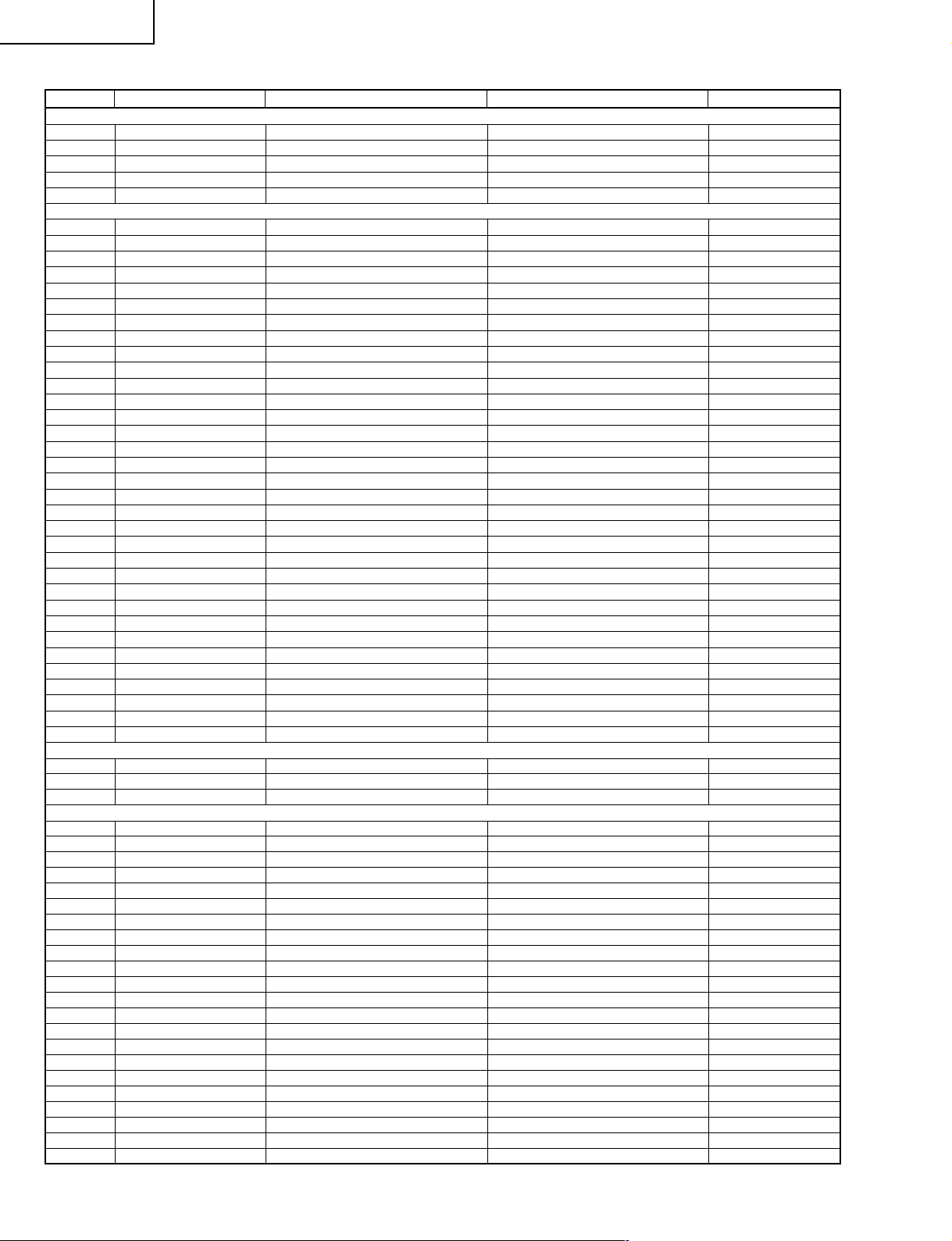
LIST OF CHANGED PARTS
Ref. No. Description LC-37D40U LC-37SH20U Note
PRINTED WIRING BOARD ASSEMBLIES
MAIN Unit DUNTKD640FM06 DUNTKD640FM08 Some parts change
R/C,LED Unit DUNTKD641FM06 DUNTKD641FM08 Some parts change
IF Unit DUNTKD643FM06 DUNTKD643FM08 Some parts change
KEY Unit DUNTKD716FM06 DUNTKD716FM08 No parts change
POWER Unit RDENCA161WJQZ RDENCA161WJQZ
MAIN Unit
C1513 Capacitor RC-KZA510WJPZY — Delete
C1515 Capacitor VCKYCZ1CB103KY — Delete
C1517 Capacitor RC-KZA510WJPZY — Delete
C1519 Capacitor VCKYCZ1EF104ZY — Delete
D1503 Diode VHDDAN202K/-1Y — Delete
D1505 Diode VHD1SS355//-1Y — Delete
D1509 Diode VHD1SS226//-1Y — Delete
D1513 Diode VHD1SS226//-1Y — Delete
D1514 Diode VHD1SS355//-1Y — Delete
FB1510 Ferrite Bead RBLN-0210TAZZY — Delete
IC1501 IC VHi24LC2BiN-1Y — Delete
L1506 Coil RCiLFA116WJZZY — Delete
L1507 Coil RCiLFA116WJZZY — Delete
L1508 Coil RCiLFA116WJZZY — Delete
L1509 Coil RCiLFA116WJZZY — Delete
Q1503 Transistor VSUM6K1NTN+-1Y — Delete
Q1506 Transistor VSKRC404E++-1Y — Delete
Q1508 Transistor VSKRC404E++-1Y — Delete
Q1514 Transistor VSiMD2A////-1Y — Delete
R1501 Resistor VRS-CZ1JF102JY — Delete
R1532 Resistor VRS-CZ1JF473FY — Delete
R1535 Resistor VRS-CZ1JF473FY — Delete
R1536 Resistor VRS-CZ1JF100JY — Delete
R1539 Resistor VRS-CZ1JF473FY — Delete
R1540 Resistor VRS-CZ1JF100JY — Delete
R1545 Resistor VRS-CY1JF474JY — Delete
R1546 Resistor VRS-CY1JF474JY — Delete
R1555 Resistor VRS-CZ1JF103JY — Delete
R1559 Resistor VRS-CZ1JF103JY — Delete
R1633 Resistor — VRS-CZ1JF103JY Add
R8124 Resistor — VRS-CZ1JF103JY Add
R8188 Resistor VRS-CZ1JF103JY — Delete
SC1501 Socket QSOCZA072WJZZQ — Delete
R/C,LED Unit
C103 Capacitor VCKYCY1HF103ZY — Delete
C104 Capacitor VCEASX1CN106MY — Delete
IC101 IC VHiTPS850++-1Y — Delete
IF Unit
C511 Capacitor RC-KZA237WJZZY — Delete
C513 Capacitor RC-KZA237WJZZY — Delete
C517 Capacitor RC-KZA237WJZZY — Delete
C533 Capacitor — VCKYCY1EF104ZY Add
C534 Capacitor — VCKYCY1EF104ZY Add
C535 Capacitor — VCKYCY1EF104ZY Add
D515 Diode VHDDAN217U+-1Y — Delete
D516 Diode VHDDAN217U+-1Y — Delete
D517 Diode VHDDAN217U+-1Y — Delete
FB511 Ferrite Bead RBLN-A204WJZZY — Delete
FB514 Ferrite Bead RBLN-A204WJZZY — Delete
FB517 Ferrite Bead RBLN-A204WJZZY — Delete
J502 Jack QTANJA093WJZZ QTANJA101WJZZ
R519 Resistor VRS-TQ2BD750JY — Delete
R520 Resistor VRS-CY1JF102JY — Delete
R525 Resistor VRS-TQ2BD750JY — Delete
R530 Resistor VRS-TQ2BD750JY — Delete
R554 Resistor VRS-CY1JF220JY — Delete
R555 Resistor VRS-CY1JF220JY — Delete
R556 Resistor VRS-CY1JF220JY — Delete
R558 Resistor VRS-CY1JF101JY — Delete
R602 Resistor — VRS-CY1JF000JY Add
2
Page 3
LC-37SH20U
2
3
3
1.5k ohm
10W
0.15 µF
TEST PROBE
TO EXPOSED
METAL PARTS
CONNECT TO
KNOWN EARTH
GROUND
DVM
AC SCALE
IMPORTANT SERVICE SAFETY PRECAUTION
Ë
Service work should be performed only by qualified service technicians who are thoroughly familiar with all safety checks and the servicing guidelines which follow:
WARNING
1. For continued safety, no modification of any circuit
should be attempted.
2. Disconnect AC power before servicing.
CAUTION: FOR CONTINUED PROTECTION
AGAINST A RISK OF FIRE REPLACE ONLY WITH
SAME TYPE F701 (8A, 125V) AND F4701, F5701
(3A~, 250V, 115°C) FUSE.
BEFORE RETURNING THE RECEIVER
(Fire & Shock Hazard)
Before returning the receiver to the user, perform
the following safety checks:
1. Inspect all lead dress to make certain that leads are
not pinched, and check that hardware is not lodged
between the chassis and other metal parts in the
receiver.
2. Inspect all protective devices such as non-metallic
control knobs, insulation materials, cabinet backs,
adjustment and compartment covers or shields, isolation
resistor-capacitor networks, mechanical insulators, etc.
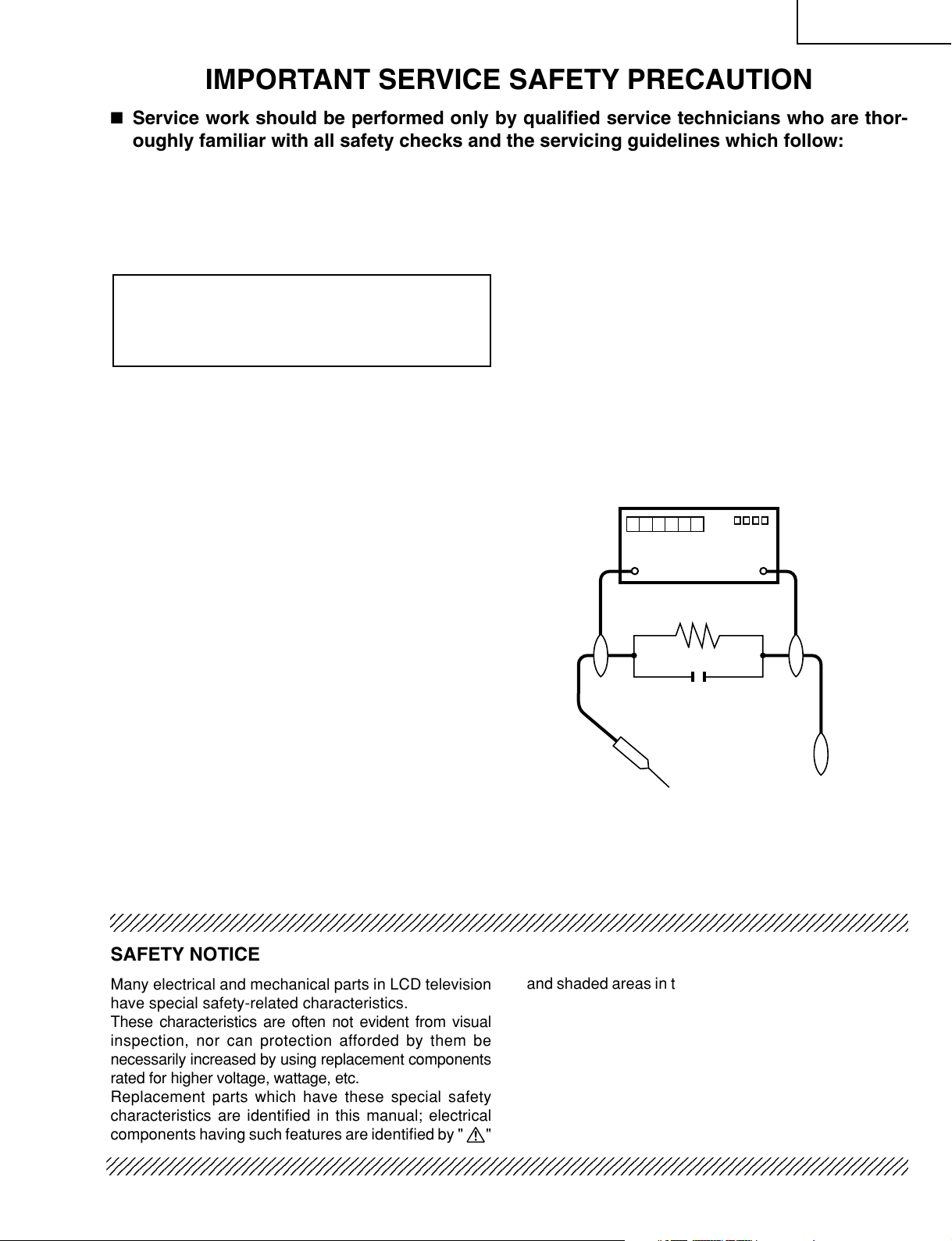
3. To be sure that no shock hazard exists, check for
leakage current in the following manner.
• Plug the AC cord directly into a 120 volt AC outlet.
• Using two clip leads, connect a 1.5k ohm, 10 watt
resistor paralleled by a 0.15µF capacitor in series with
all exposed metal cabinet parts and a known earth
ground, such as electrical conduit or electrical ground
connected to an earth ground.
• Use an AC voltmeter having with 5000 ohm per volt, or
higher, sensitivity or measure the AC voltage drop
across the resistor.
• Connect the resistor connection to all exposed metal
parts having a return to the chassis (antenna, metal
cabinet, screw heads, knobs and control shafts,
escutcheon, etc.) and measure the AC voltage drop
across the resistor.
All checks must be repeated with the AC cord plug
connection reversed. (If necessary, a nonpolarized
adaptor plug must be used only for the purpose of
completing these checks.)
Any reading of 0.75V rms (this corresponds to 0.5 mA
rms AC.) or more is excessive and indicates a potential
shock hazard which must be corrected before returning
the monitor to the owner.
234567890123456789012345678901212345678901234567890123456789012123456789012345678901234567890121
SAFETY NOTICE
Many electrical and mechanical parts in LCD television
have special safety-related characteristics.
These characteristics are often not evident from visual
inspection, nor can protection afforded by them be
necessarily increased by using replacement components
rated for higher voltage, wattage, etc.
Replacement parts which have these special safety
characteristics are identified in this manual; electrical
components having such features are identified by " å"
2345678901234567890123456789012123456789012345678901234567890121234567890123456789012345678901212
2345678901234567890123456789012123456789012345678901234567890121234567890123456789012345678901212
and shaded areas in the
Schematic Diagrams
Replacement Parts Lists
.
For continued protection, replacement parts must be
identical to those used in the original circuit.
The use of a substitute replacement parts which do not
have the same safety characteristics as the factory
recommended replacement parts shown in this service
manual, may create shock, fire or other hazards.
3
and
Page 4
LC-37SH20U
1
1
1
PRECAUTIONS A PRENDRE LORS DE LA REPARATION
Ë
La réparation ne peut être effectuée que par un technicien spécialisé qui s'est parfaitement
accoutumé à toute vérification de sécurité et aux conseils suivants.
AVERTISSEMENT
1. Pour la sécurité continue, n'entreprendre aucune
modification de tout circuit.
2. Débrancher l'alimentation CA avant la réparation.
PRECAUTION: POUR LA PROTECTION
CONTINUE CONTRE LES RISQUES
D'INCENDIE, REMPLACER LE FUSIBLE PAR UN
FUSIBLE DE MEME TYPE F701 (8A, 125V) UND
F4701, F5701 (3A~, 250V, 115°C) FUSE.
AVANT DE RENDRE LE RECEPTEUR A
L’UTILISATEUR (Incendie et choc électrique)
Avant de rendre le récepteur à l'utilisateur, effectuer
les vérifications suivantes.
1. Inspecter tous les faisceaux de câbles pour s'assurer
que les fils ne soient pas pincés ou qu'un outil ne soit
pas placé entre le châssis et les autres pièces
métalliques du récepteur.
2. Inspecter tous les dispositifs de protection comme les
boutons de commande non-métalliques, les isolants,
le dos du coffret, les couvercles ou blindages de réglage
et de compartiment, les réseaux de résistance-capacité,
les isolateurs mécaniques, etc.
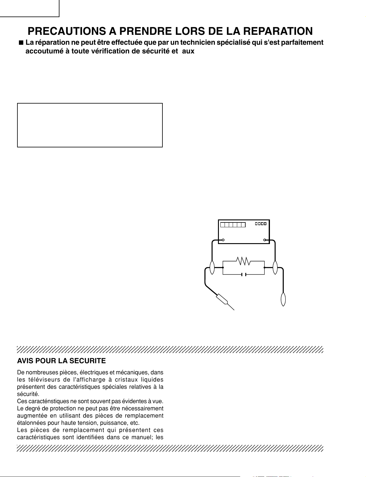
3. S'assurer qu'il n'y ait pas de danger d'électrocution en
vérifiant la fuite de courant, de la facon suivante:
• Enficher le cordon d'alimentation directement dans une
prise de 120V CA.
• A l'aide de deux fils à pinces, brancher une résistance
de 1.5kΩ 10 watts en parallèle avec un condensateur
de 0.15µF en série avec toutes les pièces métalliques
exposées du coffret et une terre connue comme une
conduite électrique ou une prise de terre branchée à la
terre.
• Utiliser un voltmètre CA d'une sensibilité d'au moins
5000Ω/V pour mesurer la chute de tension CA en
travers de la résistance.
• Toucher avec la sonde d'essai les pièces métalliques
exposées qui présentent une voie de retour au châssis
(antenne, coffret métallique, tête des vis, arbres de
commande et des boutons, écusson, etc.) et mesurer
la chute de tension CA en travers de la résistance.
Toutes les vérifications doivent être refaites après avoir
inversé la fiche du cordon d'alimentation. (Si nécessaire,
une prise d'adpatation non polarisée doit être utilisée
dans le but de terminer ces vérifications.)
La tension de pointe mesurèe ne doit pas dépasser
0.75V RMS (correspondante au courant CA de pointe
de 0.5mA RMS). Dans le cas contraire, il y a une
possibilité de choc électrique qui doit être supprimée
avant de rendre le récepteur au client.
DVM
ECHELLE CA
1.5k ohm
10W
0.15 µF
SONDE D'ESSAI
AUX PIECES
METALLIQUES
EXPOSEES
BRANCHER A UNE
TERRE CONNUE
23456789012345678901234567890121234567890123456789012345678901212345678901234567890123456789012
AVIS POUR LA SECURITE
De nombreuses pièces, électriques et mécaniques, dans
les tél éviseurs de l'afficharge à cristaux liquides
présentent des caractéristiques spéciales relatives à la
sécurité.
Ces caracténstiques ne sont souvent pas évidentes à vue.
Le degré de protection ne peut pas être nécessairement
augmentée en utilisant des pièces de remplacement
étalonnées pour haute tension, puissance, etc.
Les pièces de remplacement qui présentent ces
caractéristiques sont identifiées dans ce manuel; les
23456789012345678901234567890121234567890123456789012345678901212345678901234567890123456789012
23456789012345678901234567890121234567890123456789012345678901212345678901234567890123456789012
pièces électriques qui présentent ces particularités sont
identifiées par la marque " å " et hachurées dans la
des pièces de remplacement
schématiques
.
et les
diagrammes
Pour assurer la protection, ces pièces doivent être
identiques à celles utilisées dans le circuit d'origine.
L'utilisation de pièces qui n'ont pas les mêmes
caractéristiques que les pièces recommandées par
l'usine, indiquées dans ce manuel, peut provoquer des
électrocutions, incendies ou autres accidents.
4
liste
Page 5
LC-37SH20U
Precautions for using lead-free solder
1 Employing lead-free solder
"All PWBs" of this model employs lead-free solder. The LF symbol indicates lead-free solder, and is attached on
the PWBs and service manuals. The alphabetical character following LF shows the type of lead-free solder.
Example:
L Fa
Indicates lead-free solder of tin, silver and copper.
2 Using lead-free wire solder
When fixing the PWB soldered with the lead-free solder, apply lead-free wire solder. Repairing with conventional
lead wire solder may cause damage or accident due to cracks.
As the melting point of lead-free solder (Sn-Ag-Cu) is higher than the lead wire solder by 40°C, we recommend
you to use a dedicated soldering bit, if you are not familiar with how to obtain lead-free wire solder or soldering bit,
contact our service station or service branch in your area.
3 Soldering
As the melting point of lead-free solder (Sn-Ag-Cu) is about 220°C which is higher than the conventional lead
solder by 40°C, and as it has poor solder wettability, you may be apt to keep the soldering bit in contact with the
PWB for extended period of time. However, Since the land may be peeled off or the maximum heat-resistance
temperature of parts may be exceeded, remove the bit from the PWB as soon as you confirm the steady soldering
condition.
Lead-free solder contains more tin, and the end of the soldering bit may be easily corroded. Make sure to turn on
and off the power of the bit as required.
If a different type of solder stays on the tip of the soldering bit, it is alloyed with lead-free solder. Clean the bit after
every use of it.
When the tip of the soldering bit is blackened during use, file it with steel wool or fine sandpaper.
Be careful when replacing parts with polarity indication on the PWB silk.
Lead-free wire solder for servicing
Part No. ★ Description Code
ZHNDAi123250E J φ0.3mm 250g(1roll) BL
ZHNDAi126500E J φ0.6mm 500g(1roll) BK
ZHNDAi12801KE J φ1.0mm 1kg(1roll) BM
5
Page 6
LC-37SH20U
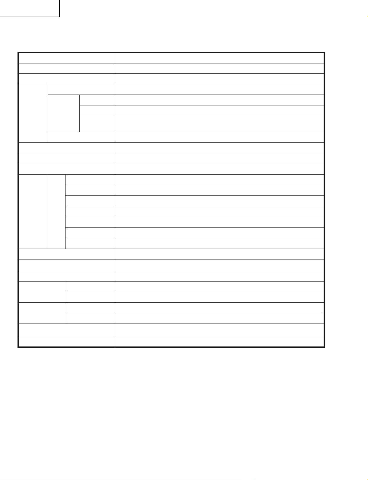
SPECIFICATIONS
Item
LCD panel
Number of dots
TV-standard (CCIR)
TV
Function
Brightness
Viewing angles
Audio out
Terminals
Receiving
Channel
Audio multiplex
Rear
Model: LC-37SH20U
37" Advanced Super View & BLACK TFT LCD
3,147,264 dots (1366 768 3 dots)
American TV Standard ATSC/NTSC System
VHF/UHF
CATV
Digital Terrestrial
Broadcast (8VSB)
INPUT 1
INPUT 2
INPUT 3
INPUT 4
ANTENNA
DIGITAL AUDIO OUTPUT
VHF 2-13ch, UHF 14-69ch
1-135ch* (non-scrambled channel only)
2-69ch
BTSC System
450cd/m
H : 170° V : 170°
10W 2
AV in, COMPONENT in
AV in
S-VIDEO in, AV in
Audio in, HDMI in with HDCP
75 Unbalance, F Type 1 for Analog (VHF/UHF/CATV) and Digital (AIR/CABLE)
Ω
Optical Digital audio output 1 (PCM/Dolby Digital)
××
2
×
×
×
OUTPUT
OSD language
Power Requirement
Power Consumption
Weight
Dimension
××
(W H D)
Accessories
Operating temperature
* Emergency alert messages via Cable are unreceivable.
As part of policy of continuous improvement, SHARP reserves the right to make design and specification changes for product
•
improvement without prior notice. The performance specification figures indicated are nominal values of production units.
There may be some deviations from these values in individual units.
w/o stand
with stand
w/o stand
with stand
Audio out
English/French/Spanish
AC 120 V, 60 Hz
186 W
46.3 lbs./21.5 kg
53.0 lbs./24.0 kg
25
36
36
Remote control unit (×1), AC cord (×1), “AA” size battery (×2), Cable clamp (×1),
Cable tie (×1), Stand unit (×1), Operation manual (×1)
×
/32 2561/64 445/64 inch
25
××
/32 285/16 129/32 inch
++ +
32°F to 104°F (0°C to 40°C)
×
6
Page 7
OPERATION MANUAL
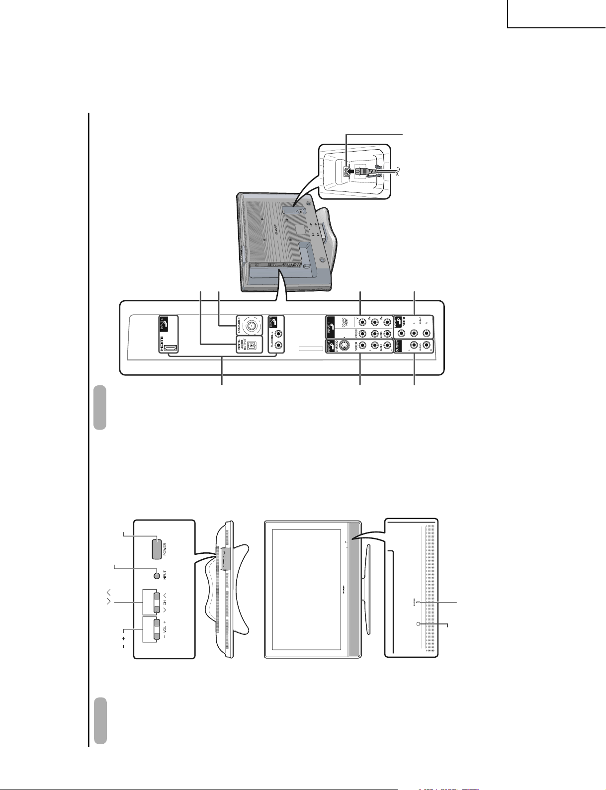
Part names
POWER button
TV (Front)
Channel buttons
(CH /)
Volume buttons (VOL /)
INPUT button
POWER indicator*
Remote control sensor
INPUT 4
INPUT 3
AUDIO OUTPUT
DIGITAL AUDIO OUTPUT terminal
Antenna/Cable in
AC INPUT terminal
TV (Rear)
terminals
terminals
INPUT 1 terminals
INPUT 2 terminals
terminals
LC-37SH20U
7
Page 8
LC-37SH20U
1
3
5
4
11
2
16
12
13
14
15
18
17
19
22
20
21
9
10
7
8
6
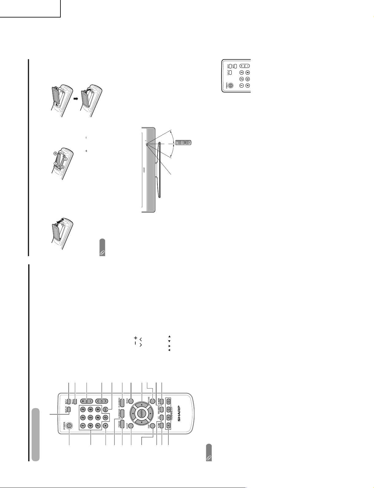
Part names
1 POWER: Switch the TV power on or enter standby
mode.
2 0 – 9: Set the channel.
3 • (DOT):
4 SURROUND: Select Surround settings.
5 FREEZE: Set the still image. Press again to return to
normal screen.
6 SLEEP: Set the sleep timer.
7 EXIT: Turn off the menu screen.
8 CC: Display captions from a closed-caption source.
9 AUDIO: Select the MTS/SAP or the audio mode during
multi-channel audio broadcasts.
10 FAVORITE CH
A, B, C, D: Select four preset favorite channels in four
different categories.
While watching, you can toggle the selected channels by
pressing A, B, C and D
11 DISPLAY: Display the channel information.
12 INPUT: Select a TV input source. (TV, INPUT 1, INPUT 2,
INPUT 3, INPUT 4)
13 MUTE: Mute the sound.
14 VOL /: Set the volume.
15 CH / : Select the channel.
16 ENT: Jump to a channel after selecting with the 0–9
buttons.
17 FLASHBACK: Return to the previous channel or input
external mode.
18 MENU: Display the menu screen.
19 /
///ENTER: Select a desired item on the
screen.
20 RETURN: Return to the previous menu screen.
21 VIEW MODE: Select the screen size.
22 AV MODE: Select an audio or video setting. (STANDARD,
MOVIE, GAME, USER, DYNAMIC (Fixed), DYNAMIC.)
Remote control unit
NOTE
• When using the remote control unit, point it at the TV.
30°30°
QUICK REFERENCE
If the remote control fails to operate TV functions, replace the batteries in the remote control unit.
1 Open the battery cover.
• Place the batteries with their terminals
corresponding to the ( ) and ( )
indications in the battery compartment.
NOTE
Improper use of batteries can result in chemical leakage or explosion. Be sure to follow the instructions below.
• Do not mix batteries of different types. Different types of batteries have different characteristics.
• Do not mix old and new batteries. Mixing old and new batteries can shorten the life of new batteries or cause chemical
leakage in old batteries.
• Remove batteries as soon as they are worn out. Chemicals that leak from batteries that come in contact with skin can cause
a rash. If you find any chemical leakage, wipe thoroughly with a cloth.
• The batteries supplied with this product may have a shorter life expectancy due to storage conditions.
• If you will not be using the remote control unit for an extended period of time, remove batteries from it.
Remote control
sensor
2 Insert two "AA" size batteries
(supplied with the product).
3 Close the battery cover.
IMPORTANT:
The POWER indicator on the television should light GREEN indicating you have power to the television.
If the POWER indicator on the television still does not light up, press POWER on the
remote control to turn the power on.
IMPORTANT:
IF THE UNIT DOES NOT POWER ON - UNPLUG THE TELEVISION FROM THE OUTLET AND REPEAT THE
INSTALLATION STEPS.
IF YOU STILL ENCOUNTER NO POWER, PLEASE CONTACT US AT 1-800-BE-SHARP.
Please refer to the BASIC ADJUSTMENT SETTINGS SECTION for EZ Setup and basic channel setup functions
and USING EXTERNAL EQUIPMENT SECTION for other device connections (DVD, VCR, AUDIO, etc) in your
operation manual.
16'4" (5 m)
8
Page 9
INPUT SOURCE
TV
INPUT1
INPUT2
INPUT3
INPUT4
Displaying an external equipment
image
This explanation is for the setting when connecting a
DVD player to the INPUT1 terminal.
The setting is stored and can be selected on the "INPUT
SOURCE" menu.
CAUTION
• To protect equipment, always turn off the TV before
connecting a DVD player, VCR, Digital TV tuner, HDMI
equipment, game console, camcorder or other external
equipment.
NOTE
• Please read the relevant operation manual (DVD player,
etc.) carefully before making connections.
• Each time INPUT is pressed, the input source toggles.
• Refer to your external equipment operation manual for the
signal type.
Using external equipment
NOTE
• If the image does not come in clearly, you may need to
change the input signal type setting on the "Input Select"
menu.
Selecting the INPUT signal
Press MENU and the MENU screen displays.
Press / to select "Option".
Press / to select "Input Select", and then
press ENTER.
Select the desired signal type.
For INPUT1 signal
1
2
4
3
Auto
COMPONENT
VIDEO
(Example)
Press MENU to exit.
5
You can connect many types of external equipment to your TV like a DVD player, VCR, Digital TV tuner, HDMI
equipment, game console or camcorder. To view external source images, select the input source from
INPUT on
the remote control unit or on the TV.
To watch a DVD image, select "INPUT1" from "INPUT
SOURCE" menu using
INPUT on the remote control
unit or on the TV.
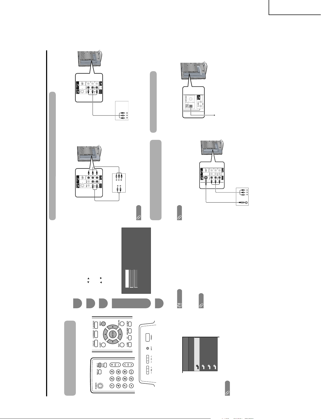
Connecting a DVD player or a Digital TV STB (Air or Cable)
You can use the INPUT 1, INPUT 2 or INPUT 3 terminals when connecting to a DVD player, a Digital TV STB (Air or
Cable) and other audiovisual equipment.
DVD player/
Digital TV STB
NOTE
• See page for connecting a DVD player or a Digital TV STB to the HDMI terminal.
Connecting a VCR, game console or
camcorder
A VCR, game console, camcorder and other
audiovisual equipment can be conveniently connected
using the INPUT 1 to 3 terminals.
NOTE
• The S-video terminal takes priority over the video terminals.
(INPUT 3 only)
VCR/Game console/
Camcorder
Using Digital Audio Output
It is possible to output audio through the DIGITAL
AUDIO OUTPUT terminal.
PCM audio outputs from the terminal.
When using component cable. (INPUT 1) When using composite cable. (INPUT 1, 2 or 3)
Component video
cable (commercially
available)
AV cable
(commercially available)
Audio cable
(commercially
available)
S-video cable
(commercially
available)
AV cable (commercially
available)
To optical digital input of
external audio devices
DVD player/
Digital TV STB
Optical fiber cable
LC-37SH20U
9
Page 10

LC-37SH20U
INPUT SOURCE
TV
INPUT1
INPUT2
INPUT3
INPUT4
Connecting HDMI equipment
You can use the INPUT 4 terminal when connecting HDMI equipment.
HDMI cable (Commercially
available)
Press / / / to select the desired
setting and press ENTER.
NOTE
• Refer to your external equipment operation manual for the
signal type.
Using external equipment
When using an HDMI-DVI
conversion cable, input the
audio signal to AUDIO terminal
of INPUT 4.
HDMI equipment
Displaying an image from HDMI
equipment
To watch an HDMI equipment image, select
"INPUT4" from "INPUT SOURCE" menu
using INPUT on the remote control unit or on
the TV.
Press MENU and the MENU screen displays.
Press / to select "Option".
Press / to select “HDMI Setup”, and then
press ENTER.
Press / to select the desired item and
press ENTER.
1
2
3
4
5
6
HDMI
Setup
items
Selectable
items
Description
Signal
Type
Auto View
Audio
Select
RGB/YCbCr 4:4:4/
YCbCr 4:2:2
Digital/Analog
Select the video signal type from
the HDMI terminal.
Set whether or not to use
View Mode based on signal
recognition, including an HDMI
signal.
Select "Digital"” for an audio
signal via the HDMI terminal.
Select "Analog" for an audio
signal via the R-AUDIO -L
terminal.
MENU
[
Option
...
HDMI Setup
]
Option
Digital Noise Reduction
Output Select
Audio Only
Quick Shoot
[Fixed]
HDMI Setup
[Low]
Press MENU to exit.
7
[Off]
Enable/Disable
Picture
Setup
Audio
Option
Power Control
Digital Setup
ENTER
: Select : Enter
MENU
: Exit
RETURN
: Back
Menu items
List of menu items to help you with operations
Basic adjustment settings
Backlight
Contrast
Brightness
Color
Tint
Sharpness
Advanced
Color Temp.
Black
3D-Y/C
Monochrome
Film Mode
EZ Setup
CH Setup
Antenna Setup-DIGITAL
Input Skip
Input Label
Parental CTRL
Position
Picture Flip
Standby Mode
Language
Reset
Treble
Bass
Balance
Surround
Audio Only
Digital Noise Reduction
Input Select
HDMI Setup
Output Select
Quick Shoot
Color System
Caption Setup
Program Title Display
Favorite CH
No Signal Off
No Operation Off
Audio Setup
Menu operation buttons
Use the following buttons on the remote control to
operate the menu.
MENU: Press to open or close the menu screen.
///: Press to select a desired item on the
screen or adjust a selected item.
ENTER: Press to go to the next step or complete
the setting.
RETURN: Press to return to the previous step.
The bar above is an operational guide for
the remote control. The bar will change in
accordance with each menu setting screen.
10
Page 11
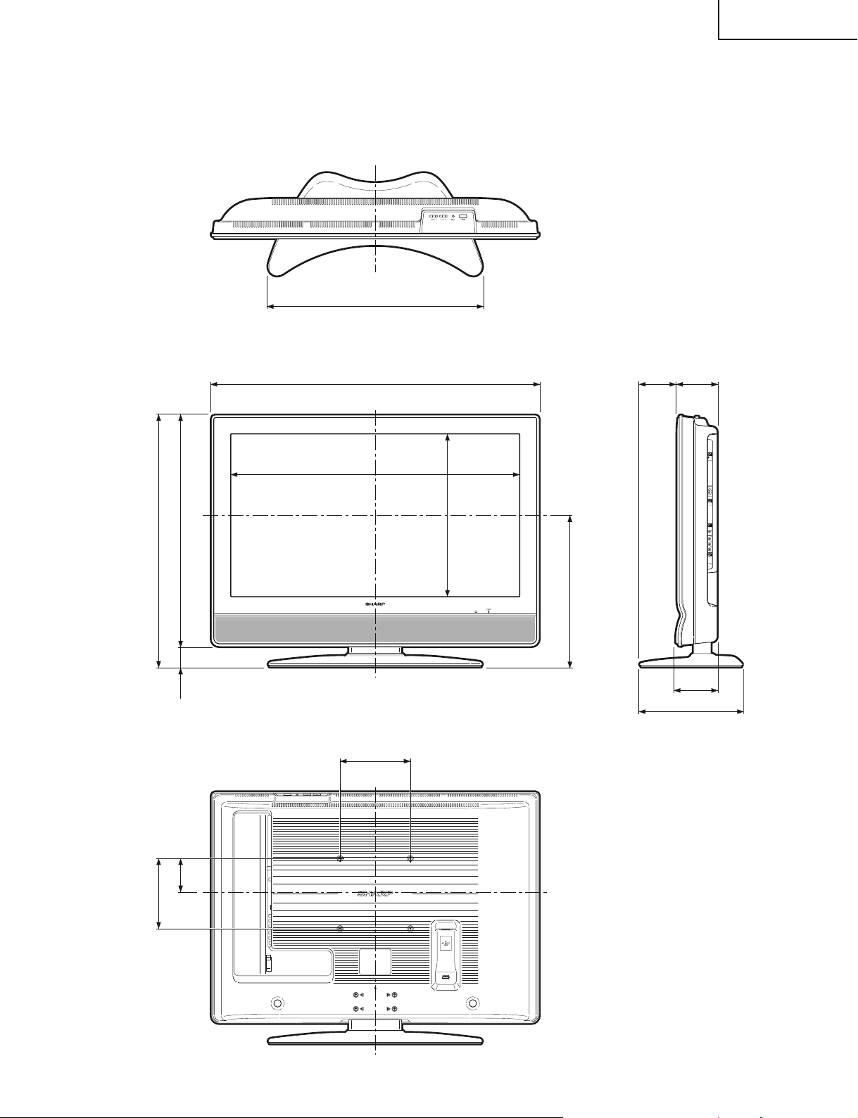
Unit: inch/(mm)
77/8 (200)
32
25
/64 (822.6)
36
25
/32 (934) 457/64 (124)417/32 (115)
12
9
/32 (312)
4
45
/64 (119)
24
13
/16 (630)
7
7
/
8
(200)
3
25
/
32
(96)
18
17
/
64
(463.8)
17
1
/
16
(433)
28
5
/
16
(719)
25
61
/
64
(659)2
3
/
8
(60)
LC-37SH20U
DIMENSIONS
11
Page 12

LC-37SH20U
REMOVING OF MAJOR PARTS
1. Remove the stand fixing screws (4 pcs.).
2. Remove the terminal screws (6 pcs.).
3. Remove the cabinet B fixing screws (9 pcs.).
4. Remove the cabinet B after opening from the direction of an arrow.
Cabinet B
3
Cabinet A
2
1
4
Stand
12
Page 13

5. Remove the 6 lock screws from the right and left center angles and take out both center angles.
6. Remove the stand cover fixing screws (3 pcs.).
7. Remove the stand assist angle fixing screws (2 pcs.).
8. Remove the stand fixing angle fixing screws (4 pcs.).
9. Remove the main PWB shield fixing screws (5 pcs.).
5
10. Disconnect all the connectors from all the PWBs.
Center Angle (R)
9
LC-37SH20U
5
Center Angle (L)
Main PWB Shield
5
5
Main PWB
IF PWB
Key PWB
10
R/C, LED PWB
10
10
10
Power PWB
10
13
Stand Fixing Angle
Stand Assist Angle
Stand Cover
8
7
6
Page 14

LC-37SH20U
11. Remove the PWB unit ass’y fixing screws (4 pcs.).
12. Remove the top cover ass’y.
13. Remove the key PWB fixing screws (3 pcs.).
14. Remove the 8 lock screws from the right and left speakers and take out both speakers.
15. Remove the R/C,LED PWB fixing screws (2 pcs.).
Top Cover Ass'y
Key PWB
11
PWB Unit Ass'y
15
R/C, LED PWB
14
12
Speaker (R)
13
Speaker (L)
14
14
Page 15
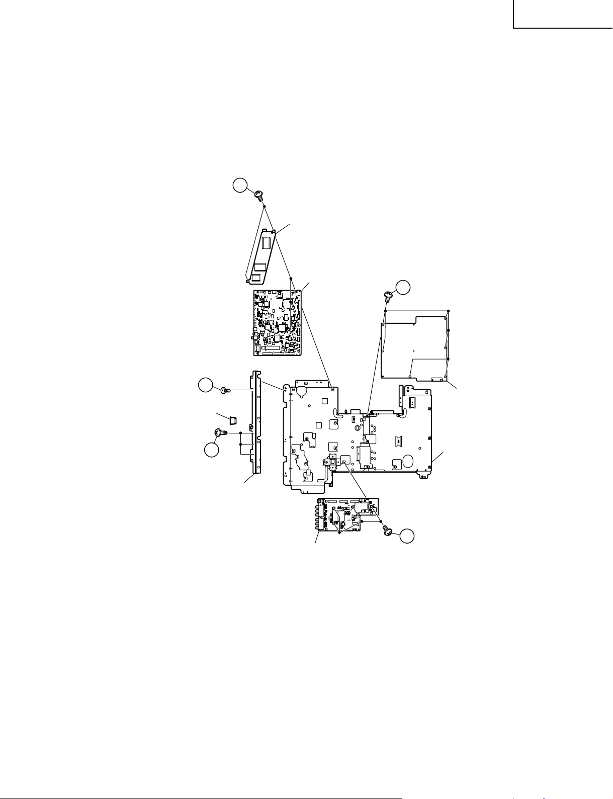
16. Remove the SD card cover and terminal angle fixing screws (4 pcs.).
17. Remove the power PWB fixing screws (6 pcs.).
18. Remove the IF PWB fixing screws (4 pcs.).
19. Remove the heat sink and main PWB fixing screws (4 pcs.).
19
Heat Sink
Main PWB
LC-37SH20U
17
16
SD Card Cover
16
Terminal Angle
Power PWB
Chassis frame
18
IF PWB
15
Page 16
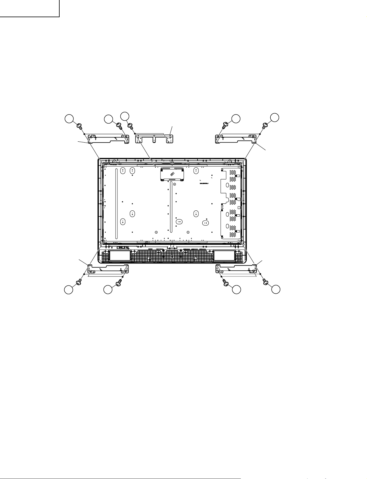
LC-37SH20U
20. Remove the center assist angle fixing screws (2 pcs.).
21. Remove the 6 lock screws from the right and left corner angles(top) and take out both center angles(top).
22. Remove the 8 lock screws from the right and left corner angles(bottom) and take out both corner angles(bottom).
21
Top Corner Angle (R)
Bottom Corner Angle (R)
22
21
20
Center Assist Angle
21
2222
21
Top Corner Angle (L)
Bottom Corner Angle (L)
22
16
Page 17

DESCRIPTION OF SCHEMATIC DIAGRAM
VOLTAGE MEASUREMENT CONDITION:
1. The voltages at test points are measured on the
stable supply voltage of AC 120V. Signals are fed
by a color bar signal generator for servicing purpose
and the above voltages are measured with a 20k
ohm/V tester.
INDICATION OF RESISTOR & CAPACITOR:
RESISTOR
1. The unit of resistance “Ω” is omitted.
(K=kΩ=1000 Ω, M=MΩ).
2. All resistors are ± 5%, unless otherwise noted.
(K= ± 10%, F= ± 1%, D= ± 0.5%)
3. All resistors are 1/16W, unless otherwise noted.
CAPACITOR
1. All capacitors are µF, unless otherwise noted.
(P=pF=µµF).
2. All capacitors are 50V, unless otherwise noted.
LC-37SH20U
CAUTION:
This circuit diagram is original one, therefore there may be a
slight difference from yours.
SAFETY NOTES:
1.DISCONNECT THE AC PLUG FROM THE AC
OUTLET BEFORE REPLACING PARTS.
2.SEMICONDUCTOR HEAT SINKS SHOULD BE
REGARDED AS POTENTIAL SHOCK HAZARDS
WHEN THE CHASSIS IS OPERATING.
IMPORTANT SAFETY NOTICE:
PARTS MARKED WITH “å” ( ) ARE
IMPORTANT FOR MAINTAINING THE SAFETY OF
THE SET. BE SURE TO REPLACE THESE PARTS
WITH SPECIFIED ONES FOR MAINTAINING THE
SAFETY AND PERFORMANCE OF THE SET.
AVIS DE SECURITE IMPORTANT:
LES PIECES MARQUEES “å” ( )SONT
IMPORTANTES POUR MAINTENIR LA SECURITE
DE L'APPAREIL.
NE REMPLACER CES PIEDES QUE PAR DES
PIECES DONT LE NUMERO EST SPECIFIE POUR
MAINTENIR LA SECURITE ET PROTEGER LE BON
FONCTIONNEMENT DE L'APPAREIL.
17
Page 18
LC-37SH20U
121110987654321
A
B
C
D
E
F
G
H
Ë
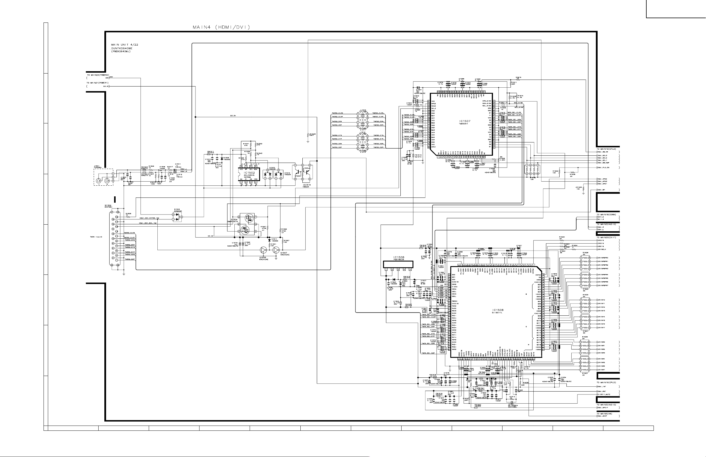
MAIN Unit-4/22
18
19
Page 19

LC-37SH20U
121110987654321
A
B
C
D
E
F
G
H
Ë
MAIN Unit-9/22
20
21
Page 20
LC-37SH20U
121110987654321
A
B
C
D
E
F
G
H
Ë
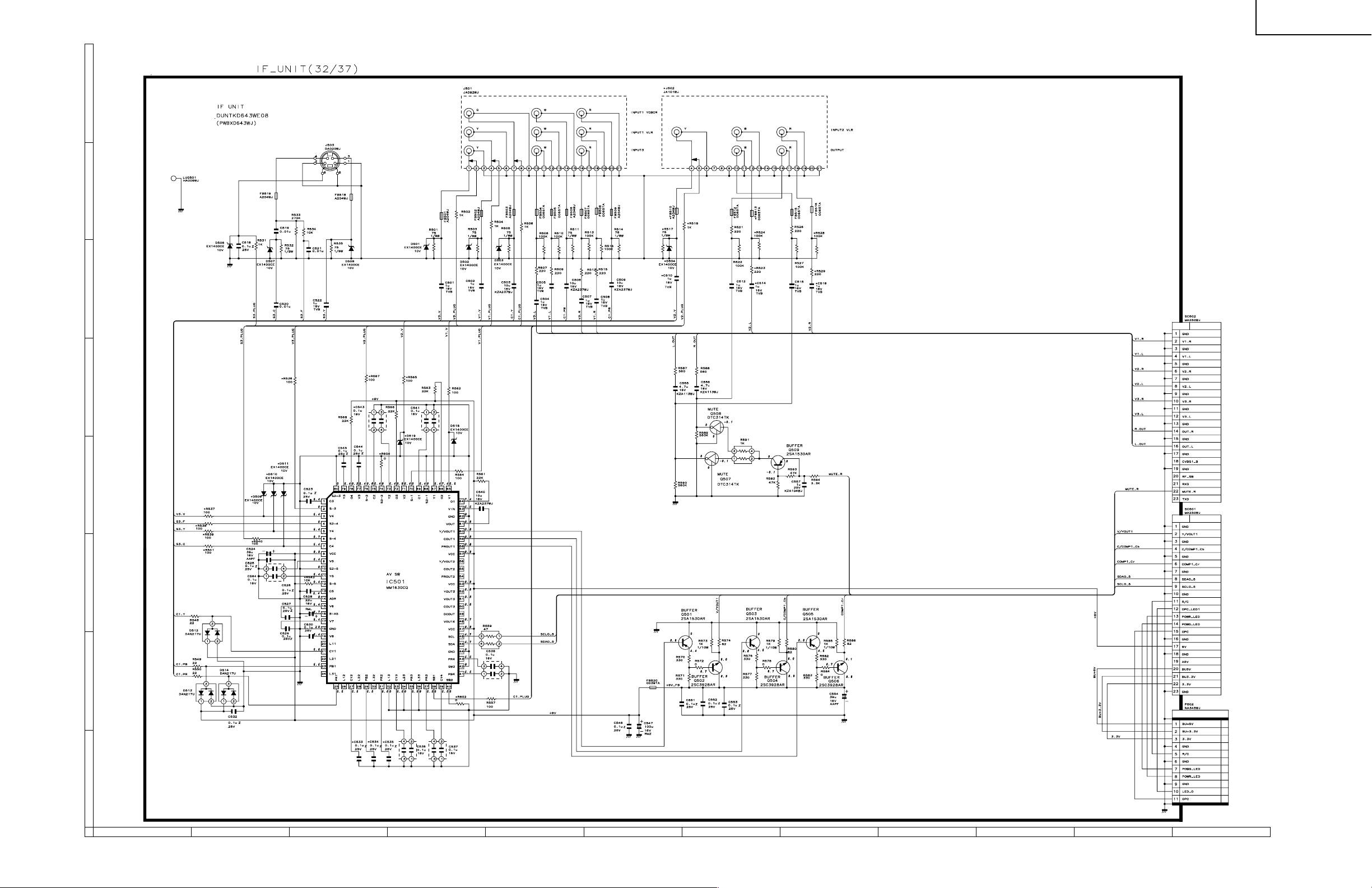
IF-Unit
22
23
Page 21

LC-37SH20U
Ref. No. Part No. ★ Description Code Ref. No. Part No. ★ Description Code
PARTS LIST
LISTE DES PIECES
PARTS REPLACEMENT
Replacement parts which have these special safety characteristics identified in this manual ; electrical components having such features are
identified by å and shaded areas in the Replacement Parts Lists and
Schematic Diagrams. The use of a substitute replacement part which
does no have the same safety characteristic as the factory recommended
replacement parts shown in this service manual may create shock, fire
or other hazards.
"HOW TO ORDER REPLACEMENT PARTS"
To have your order filled promptly and correctly, please furnish the following informations.
1. MODEL NUMBER 2. REF. NO.
3. PART NO. 4. DESCRIPTION
in USA: Contact your nearest SHARP Parts Distributor to order. For
location of SHARP Parts Distributor, Please call Toll-Free;
1-800-BE-SHARP
★ MARK: SPARE PARTS-DELIVERY SECTION
Ref. No. Part No. ★ Description Code Ref. No. Part No. ★ Description Code
Les pi`eces de rechange qui pr élelesentent ces caract éleristiques sp
éleciales de s élecurit éle, sont identifi élees dans ce manuel : les pi`eces
élelectriques qui pr élesentent ces particularit éles, sont rep éler élee
par la marque å et sont hachur élees dans les listes de pi`eces et dans
les diagrammes sch élematiques.
La substitution d'une pi`ece de rechange par une autre qui ne pr éLesente
pas les m éoemes caract éLeristiques de s élecurit éle que la pi`ece
recommand élee parl'usine et dans ce manuel de service, peut provoquer
une éLelectrocution, un incendie ou toutautre sinistre.
"COMMENT COMMANDER LES PIECES DE RECHANGE"
Pour que votre commande soit rapidement et correctement remplie,
veuillez fournir les renseignements suivants.
1. NUMERO DU MODELE 2. NO. DE REF
3. NO. DE PIECE 4. DESCRIPTION
in CANADA: Contact SHARP Electronics of Canada Limited
★ MARQUE: SECTION LIVRAISON DES PIECES DERECHANGE
CHANGE DES PIECES
Phone (416) 890-2100
PRINTED WIRING BOARD ASSEMBLYS
(NOT REPLACEMENT ITEM)
DUNTKD640FM08 R MAIN Unit —
DUNTKD641FM08 X R/C,LED Unit —
DUNTKD643FM08 X IF Unit —
DUNTKD716FM08 X KEY Unit —
RDENCA161WJQZ X POWER Unit BQ
CABINET AND MECHANICAL PARTS
1 CCABAB318WJ01 X Cabinet A Ass’y BQ
1-1
1-2
1-3 HBDGBA065WJSB X Badge, "SHARP" AF
1-4
1-5
1-6 TLABZA742WJZZ X "POP" Label AD
Not Available
Not Available
Not Available
Not Available
– Cabinet A —
– R/C,LED Cover —
– Mask Spacer-S, x2 —
– Mask Spacer-L, x2 —
LCD PANEL
NOTE: THE PARTS HERES SHOWN ARE SUPPLIED AS AN
ASSEMBLY BUT NOT INDEPENDENTLY.
R1LK370T3LZ5BY X 37" LCD Panel Module FD
Unit Ass'y
DUNTKD640FM08
MAIN Unit
RESISTORS
R1633 VRS-CZ1JF103JY R 10k 1/16W Metal Oxide AA
R8124 VRS-CZ1JF103JY R 10k 1/16W Metal Oxide AA
DUNTKD643FM08
IF Unit
CAPACITORS
C533 VCKYCY1EF104ZY X 0.1 25V Ceramic AA
C534 VCKYCY1EF104ZY X 0.1 25V Ceramic AA
C535 VCKYCY1EF104ZY X 0.1 25V Ceramic AA
RESISTORS
R602 VRS-CY1JF000JY X 0 1/16W Metal Oxide AA
MISCELLANEOUS PARTS
J502 QTANJA101WJZZ X Terminal AG
2 CCABBA767WJ01 X Cabinet B Ass’y BS
2-1
2-2 LHLDWA055WJKZ X Wire Holder, x1 AC
2-3 LHLDWA131WJKZ X Wire Holder, x1 AF
2-4
3 CCOVAB497WJ02 X Top Cover Ass’y AZ
3-1
3-2
4 CDAI-A269WJ01 X Stand Base Ass’y
4-1
4-2 CANGKA635WJ01 X Stand Base Angle Ass’y BA
4-2-1
4-2-2
4-2-3
4-3
4-4 XEBSN40P08000 X Screw, x14 AB
5 CDAI-A270WJ01 X Stand Support Ass’y AZ
5-1
5-2
5-3
6 R1LK370T3LZ5BY X
7 GCOVAA678WJKA X SD Card Cover AG
8 GCOVAB507WJKA X Stand Cover AU
9 HINDPB671WJSA X Model Label AH
10 HINDPB672WJSA X Terminal Indication Label AH
11 HINDPB715WJSA X Terminal Label AF
12 LANGKA644WJFW X Terminal Angle AL
13 LANGKA649WJFW X Stand Fixing Angle AR
14 LANGKA655WJFW X Centre Assist Angle AH
15 LANGKA663WJFW X Corner Angle, x4 AK
16 LANGTA266WJFW X Stand Assist Angle AR
17 LANGTA291WJFW X Centre Angle(R) AR
18 LANGTA292WJFW X Centre Angle(L) AR
Not Available
Not Available
Not Available
Not Available
Not Available
Not Available
Not Available
Not Available
Not Available
Not Available
Not Available
Not Available
– Cabinet B —
– Cushion Spacer, x1 —
– Top Cover —
– Operation Button —
– Stand Base —
– Stand Base Angle —
– Leg Cushion-A, x4 —
– Leg Cushion-B, x4 —
– Label —
– Stand Support —
– Support Cover —
– Screw Guide, x4 —
37" LCD Panel Module Unit Ass’y
FD
24
Page 22

CABINET AND MECHANICAL PARTS
LC-37SH20U
H
6
g
G
3-1
3
3-2
49
1-1
A
1-4
1-5
E
F
C
1-5
F
59
1-4
39
a
57
52
C
45
b
57
D
52
H
h
e
E
1-6
1-3
1
42
h
D
C
55
50
23
24
20
H
B
D
1-2
d
B
e
f
44
40
36
g
37
55
21
22
22
41
34
a
29
46
24
43
34
55
30
33
25
59
47
32
22
55
19
34
31
33
55
27
b
28
d
48
38
22
12
10
55
33
53
18
53
I
55
55
60
35
7
11
56
15
21
G
f
I
A
2
2-1
17
55
13
16
57
55
E
14
55
15
21
53
53
55
58
8
4
55
57
51
55
2-2
B
5
4-2-3
55
57
9
54
5-2
4-2-2
4-2-3
61
4-2-2
54
2-3
5-1
4-3
4-2-3
26
26
5-3
5-3
4-1
4-2-3
4-2-2
G
F
15
57
15
58
54
4-2
4-2-1
4-2-2
4-4
A
654321
25
Page 23

LC-37SH20U
Ref. No. Part No. ★ Description Code Ref. No. Part No. ★ Description Code
CABINET AND MECHANICAL PARTS
(Continued)
19 LBSHZA005WJZZ X Bush, x2 AB
20 LCHSMA286WJFW X Chassis Frame AX
21 LHLDW1173CEZZ X Wire Holder, x3 AE
22 LHLDWA043WJKZ X Wire Holder, x4 AC
23 LHLDWA048WJKZ X Wire Holder, x1 AB
24 LHLDWA092WJZZ X Wire Holder, x2 AB
25 LHLDWA096WJKZ X Wire Holder, x1 AD
26 LX-BZA147WJF8 X Screw, x4 AP
27 LX-NZ3047GEZZ X Nut AB
28 PRDARA192WJFW X Heat Sink AE
29 PRDARA204WJFW X Heat Sink AE
30 PRDARA312WJFW X Heat Sink AE
31 PRDARA330WJFW X Heat Sink AM
32 PSLDMA910WJFW X MAIN PWB Shield AV
33 PSPAZA635WJKZ X Spacer, x3 AC
34 PSPAZA700WJKZ X Spacer, x3 AD
35 QCNCWA496WJZZ X Connecting Cord AK
36
37
38 QCNW-E265WJQZ X Connecting Cord(RA) AK
39
40 QCNW-E267WJQZ X Connecting Cord(LB) AG
41
42 QCNW-E439WJQZ X Connecting Cord(LA) AH
43
44 QCNW-E537WJPZ X Connecting Cord(LV) BA
45 QCNW-E619WJQZ X Connecting Cord(SP) AK
46 DUNTKD640FM08 R MAIN Unit —
47 DUNTKD641FM08 X R/C,LED Unit —
48 DUNTKD643FM08 X IF Unit —
49 DUNTKD716FM08 X KEY Unit —
50 RDENCA161WJQZ X POWER Unit BQ
51
52 VSP1206PA034A X Speaker, x2 AP
53 XBBS740P06000 X Screw, x6 AA
54 XBBS930P06000 X Screw, x7 AA
55 XBPS730P06WS0 X Screw, x39 AB
56 XEBS930P08000 X Screw, x3 AA
57 XEBS940P10000 X Screw, x14 AB
58 XEBS940P16000 X Screw, x12 AA
59 XEBSN30P10000 X Screw, x5 AA
60 XBPS930P08000 X Screw, x1 AA
61 LX-BZA146WJF7 X Screw, x4
Not Available
Not Available
Not Available
Not Available
Not Available
Not Available
– Connecting Cord(PE) —
– Connecting Cord(PD) —
– Connecting Cord(KM) —
– Connecting Cord(SH) —
– Connecting Cord —
– Serial No. Label —
SUPPLIED ACCESSORIES
X1 LHLDW0110CESD X Cable Clamp, x1 AF
X2 LHLDWA083WJ00 X Cable Tie, x1 AD
å X3 QACCDA039WJPZ X AC Cord AR
X4 RRMCGA470WJSA X Remote Control Unit AP
X5 TCAUZA228WJZZ X Caution Card
X6 TGAN-A216WJN1 X Guarantee Card AC
X7 TINS-C311WJZZ X Operation Manual AY
X8 CDAI-A269WJ01 X Stand Base Ass'y
X9 CDAI-A270WJ01 X Stand Support Ass'y AZ
X10 LX-BZA154WJ01 X Screw AN
X11
Not Available
– "AA" size Battery, x2 —
PACKING PARTS
(NOT REPLACEMENT ITEM)
S1 SPAKCC520WJZZ – Packing Case —
S2 SPAKFB012WJZZ – Packing Case(Stand) —
S3 SPAKPA338WJZZ – Wrapping Paper —
S4 SPAKPA602WJZZ – Wrapping Paper —
S5 SPAKPA679WJZZ – Wrapping Paper(Stand) —
S6 SPAKXB032WJZZ – Buffer Material —
S7 SPAKXB089WJZZ – Buffer Material(Stand) —
S8 SSAKA0101GJZZ – Polyethylene Bag —
S9 TLABKA009WJZZ – No. Label —
SERVICE JIGS
(USE FOR SERVICING)
QCNW-C799WJPZ J RCA cable L=1500mm, AG
QCNW-D483WJQZ J 12pins L=1000mm, AX
QCNW-E068WJQZ J 6pins L=1000mm, AS
QCNW-E670WJQZ J 4-8pins L=1000mm, AP
QCNW-E671WJQZ J 10-14pins L=1000mm, AW
QCNW-E673WJQZ J 30pins L=1000mm, BE
QCNW-E674WJQZ J 7pins L=1000mm, AS
Tuner Extension
Main to Power Unit PE (PA)
Main to Power Unit PD (MI)
Main to Inverter Unit (LA)
Power to Inverter Unit (LA)
Main to Controller Unit (LV)
Main to Controller Unit (SH)
Supplied Accessories
Remote control unit (x1)
X4 X3X11
Cable clamp (x1)
X1 X7
"AA" size battery (x2)
X8
Stand Unit (x1)Cable tie (x1)
X9
X10X2
26
AC cord (x1)
Operation manual (x1)
Page 24

PACKING OF THE SET
X1
X2
X6
X4
S8
X7
X11
LC-37SH20U
S6
S6
S3
X3
S6
X5
X8
X9
X10
S4
S5
S7
S2
S1
S6
S8
27
Page 25

LC-37SH20U
COPYRIGHT © 2006 BY SHARP CORPORATION
ALL RIGHTS RESERVED.
No part of this publication may be reproduced,
stored in a retrieval system, or transmitted in
any form or by any means, electronic, mechanical,
photocopying, recording, or otherwise, without
prior written permission of the publisher.
Apr. 2006 Printed in Japan
TQ1995-S
Design and Production Information
Design : Japan
Production : SEMEX
SY. KG
SHARP CORPORATION
AV Systems Group
CS Promotion Center
Yaita, Tochigi 329-2193, Japan
 Loading...