

Page 1
LC-26D5U
LC-32D5U
LC-37D5U
SERVICE MANUAL
S35H3LC-37D5U
LCD COLOR TELEVISION
LC-26D5U
LC-32D5U
MODELS
In the interests of user-safety (Required by safety regulations in some countries) the set should be restored
to its original condition and only parts identical to those specified should be used.
OUTLINE
This model is based on the LC-26/32/37D7U and is equipped with a redesigned speaker. This Service Manual
covers the modifications alone. For the other points, refer to the LC-26/32/37D7U Ser vice Manual.
CONTENTS
» LIST OF CHANGED PARTS ...........................................................................................................................2
» IMPORTANT SERVICE SAFETY PRECAUTION ........................................................................................5
» SPECIFICATIONS........................................................................................................................................8
» OPERATION MANUAL ................................................................................................................................9
» DIMENSIONS ............................................................................................................................................16
» REMOVING OF MAJOR PARTS................................................................................................................18
» PARTS LIST ...............................................................................................................................................30
» PACKING OF THE SET .............................................................................................................................41
LC-37D5U
Page
SHARP CORPORATION
This document has been published to be used for
after sales service only.
The contents are subject to change without notice.
Page 2
LC-26D5U
LC-32D5U
LC-37D5U
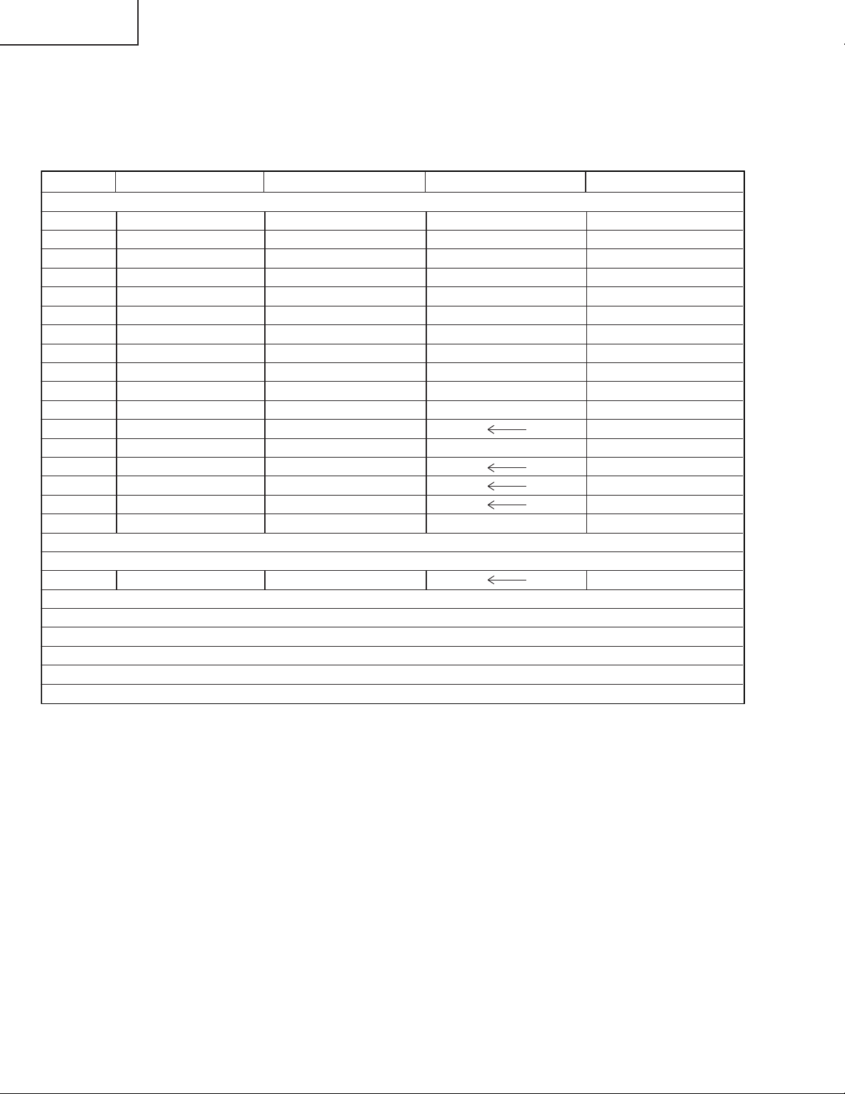
LIST OF CHANGED PARTS
LC-26D7U → LC-26D5U
Ref.No. Description LC-26D7U LC-26D5U Note
PWB ASSEMBLIES
AV Unit DUNTKC971WE01 DUNTKC971WE02 No parts changed
AV Unit DUNTKD115WE01 DUNTKD115WE02 No parts changed
KEY Unit DUNTKC972WE01 DUNTKC972WE02 No parts changed
KEY Unit DUNTKD116WE01 DUNTKD116WE02 No parts changed
R/C LED Unit DUNTKC973WE01 DUNTKC973WE02 No parts changed
R/C LED Unit DUNTKD117WE01 DUNTKD117WE02 No parts changed
SP-L Unit DUNTKC974WE01
SP-L Unit DUNTKD118WE01
SP-R Unit DUNTKC975WE01
SP-R Unit DUNTKD119WE01
LCD CONTROL Unit DUNTKC793FE10 DUNTKC793FE11 No parts changed
MAIN Unit DUNTKC794FE02
DIGITAL Unit DKEYDC956FE13 DKEYDC956FE14 No parts changed
POWER SUPPLY Unit RDENCA092WJZZ
INVERTER Unit RUNTKA094WJZZ
INVERTER GND Unit RUNTKA095WJZZ
LCD PANEL
26” Wide LCD Panel Unit RLCDTA039WJZZ
CABINET AND MECHANICAL PARTS
Please refer to a Parts list.
PACKING PARTS AND ACCESSORIES
Please refer to a Parts list.
2
Page 3
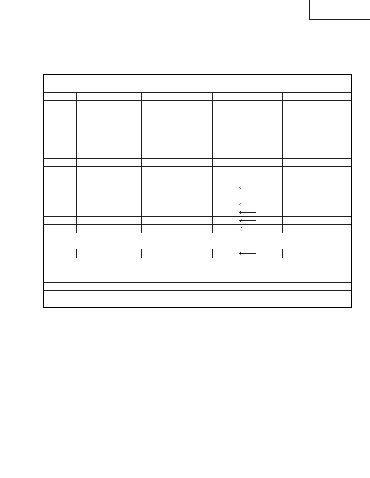
LIST OF CHANGED PARTS
LC-32D7U → LC-32D5U
Ref.No. Description LC-32D7U LC-32D5U Note
PWB ASSEMBLIES
AV Unit DUNTKC971WE01 DUNTKC971WE02 No parts changed
AV Unit DUNTKD115WE01 DUNTKD115WE02 No parts changed
KEY Unit DUNTKC972WE01 DUNTKC972WE02 No parts changed
KEY Unit DUNTKD116WE01 DUNTKD116WE02 No parts changed
R/C LED Unit DUNTKC973WE01 DUNTKC973WE02 No parts changed
R/C LED Unit DUNTKD117WE01 DUNTKD117WE02 No parts changed
SP-L Unit DUNTKC974WE01
SP-L Unit DUNTKD118WE01
SP-R Unit DUNTKC975WE01
SP-R Unit DUNTKD119WE01
LCD CONTROL Unit DUNTKC793FE06 DUNTKC793FE07 No parts changed
MAIN Unit DUNTKC794FE02
DIGITAL Unit DKEYDC956FE11 DKEYDC956FE12 No parts changed
POWER SUPPLY Unit RDENCA093WJZZ
INVERTER A Unit RUNTKA096WJZZ
INVERTER B Unit RUNTKA097WJZZ
INVERTER GND Unit RUNTKA098WJZZ
LC-26D5U
LC-32D5U
LC-37D5U
LCD PANEL
32” Wide LCD Panel Unit RLCDTA037WJZZ
CABINET AND MECHANICAL PARTS
Please refer to a Parts list.
PACKING PARTS AND ACCESSORIES
Please refer to a Parts list.
3
Page 4
LC-26D5U
LC-32D5U
LC-37D5U
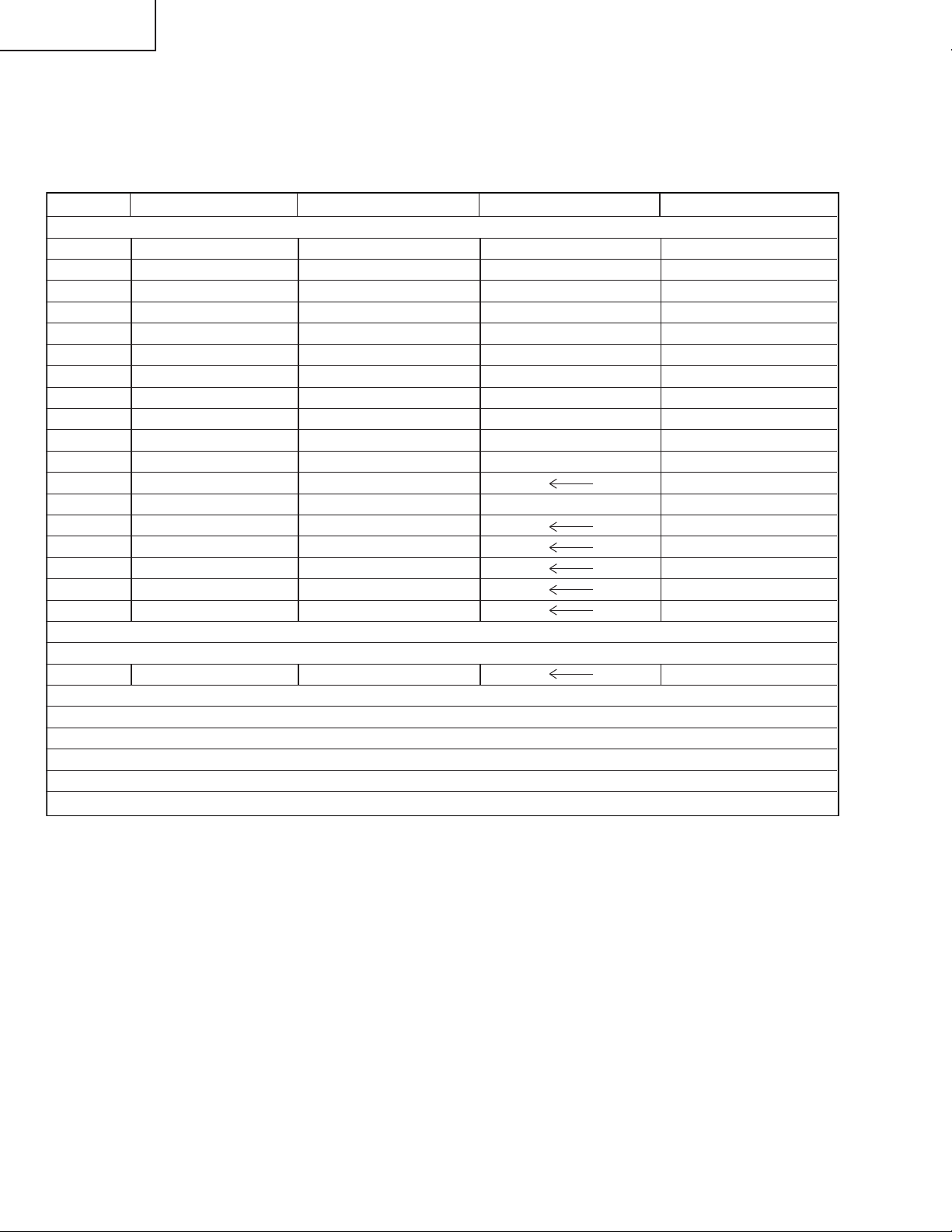
LIST OF CHANGED PARTS
LC-37D7U → LC-37D5U
Ref.No. Description LC-37D7U LC-37D5U Note
PWB ASSEMBLIES
AV Unit DUNTKC971WE01 DUNTKC971WE02 No parts changed
AV Unit DUNTKD115WE01 DUNTKD115WE02 No parts changed
KEY Unit DUNTKC972WE01 DUNTKC972WE02 No parts changed
KEY Unit DUNTKD116WE01 DUNTKD116WE02 No parts changed
R/C LED Unit DUNTKC973WE01 DUNTKC973WE02 No parts changed
R/C LED Unit DUNTKD117WE01 DUNTKD117WE02 No parts changed
SP-L Unit DUNTKC974WE01
SP-L Unit DUNTKD118WE01
SP-R Unit DUNTKC975WE01
SP-R Unit DUNTKD119WE01
LCD CONTROL Unit DUNTKC793FE08 DUNTKC793FE12 No parts changed
MAIN Unit DUNTKC794FE02
DIGITAL Unit DKEYDC956FE15 DKEYDC956FE16 No parts changed
POWER SUPPLY Unit RDENCA109WJZZ
INVERTER A Unit RUNTKA099WJZZ
INVERTER B Unit RUNTKA100WJZZ
INVERTER A GND Unit RUNTKA101WJZZ
INVERTER B GND Unit RUNTKA102WJZZ
LCD PANEL
37” Wide LCD Panel Unit RLCDTA036WJZZ
CABINET AND MECHANICAL PARTS
Please refer to a Parts list.
PACKING PARTS AND ACCESSORIES
Please refer to a Parts list.
4
Page 5
LC-26D5U
2
2
2
2
LC-32D5U
LC-37D5U
IMPORTANT SERVICE SAFETY PRECA UTION
Ë
Service work should be performed only by qualified service technicians who are thoroughly familiar with all safety checks and the servicing guidelines which follow:
WARNING
» Use an AC voltmeter ha ving with 5000 ohm per v olt,
or higher, sensitivity or measure the A C voltage drop
1. For continued safety, no modification of any circuit
should be attempted.
2. Disconnect AC power before servicing.
across the resistor.
» Connect the resistor connection to all exposed metal
parts having a return to the chassis (antenna, metal
cabinet, screw heads, knobs and control shafts,
CAUTION: FOR CONTINUED PROTECTION
AGAINST A RISK OF FIRE REPLACE ONLY WITH
SAME TYPE FUSE.
LC-26D5U:F701, F702 (3.15A, 250V)
LC-32D5U:F701, F702 (4A, 250V)
LC-37D5U:F701, F702 (5A, 250V)
F703 (2A, 250V), F704 (117°C, 2A) F705 (1A,
DC450V)
escutcheon, etc.) and measure the AC voltage drop
across the resistor.
All checks must be repeated with the AC cord plug
connection reversed. (If necessary, a nonpolarized
adaptor plug must be used only for the purpose of
completing these checks.)
Any reading of 0.75 Vrms (this corresponds to 0.5
mA rms AC.) or more is excessive and indicates a
potential shock hazard which must be corrected
before returning the monitor to the owner.
BEFORE RETURNING THE RECEIVER
(Fire & Shock Hazard)
Before returning the receiver to the user, perform
the following safety checks:
1. Inspect all lead dress to make certain that leads are
not pinched, and check that hardware is not lodged
between the chassis and other metal parts in the
receiver.
2. Inspect all protective devices such as non-metallic
control knobs, insulation materials, cabinet backs,
adjustment and compartment covers or shields,
isolation resistor-capacitor networks, mechanical
insulators, etc.
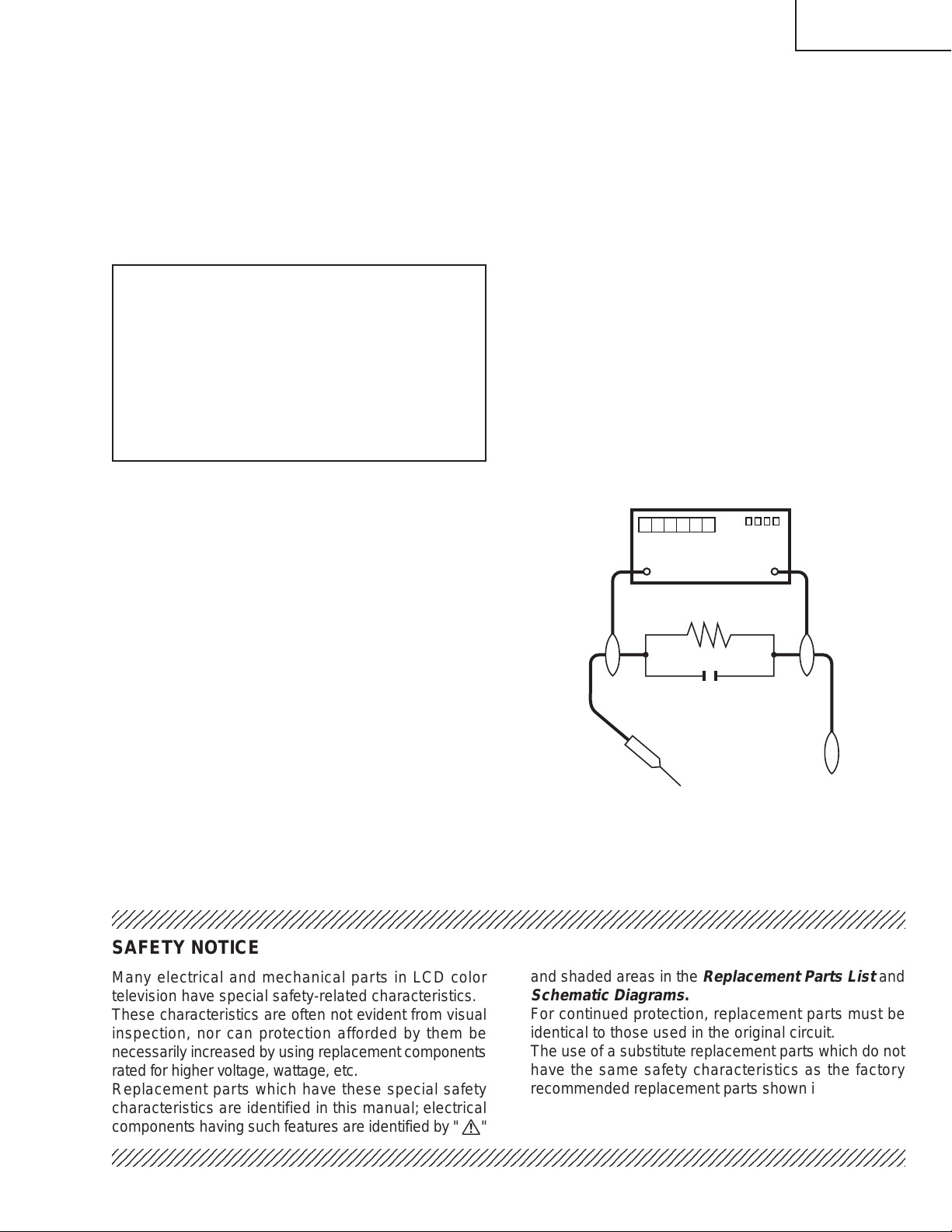
3. To be sure that no shock hazard exists, check for
leakage current in the following manner.
» Plug the AC cord directly into a 120 volt AC outlet.
» Using two clip leads, connect a 1.5k ohm, 10 watt
TO EXPOSED
METAL PARTS
resistor paralleled by a 0.15µF capacitor in series
with all exposed metal cabinet parts and a known
earth ground, such as electrical conduit or electrical
ground connected to an earth ground.
234567890123456789012345678901212345678901234567890123456789012123456789012345678901234567890121
234567890123456789012345678901212345678901234567890123456789012123456789012345678901234567890121
DVM
AC SCALE
1.5k ohm
10W
0.15 µF
TEST PROBE
CONNECT TO
KNOWN EARTH
GROUND
SAFETY NOTICE
Many electrical and mechanical parts in LCD color
television have special safety-related characteristics.
These characteristics are often not evident from visual
inspection, nor can protection afforded by them be
necessarily increased by using replacement components
rated for higher voltage , w attage , etc.
Replacement parts which have these special safety
characteristics are identified in this manual; electrical
and shaded areas in the
Schematic Diagrams
For continued protection, replacement parts must be
identical to those used in the original circuit.
The use of a substitute replacement parts which do not
have the same safety character istics as the factory
recommended replacement parts shown in this service
manual, may create shock, fire or other hazards.
components having such features are identified b y " å"
234567890123456789012345678901212345678901234567890123456789012123456789012345678901234567890121
234567890123456789012345678901212345678901234567890123456789012123456789012345678901234567890121
5
Replacement Parts List
.
and
Page 6
LC-26D5U
2
2
2
LC-32D5U
LC-37D5U
PRECAUTIONS A PRENDRE LORS DE LA REPARATION
Ë
Ne peut effectuer la réparation qu' un technicien spécialisé qui s'est parfaitement
accoutumé à toute vérification de sécurité et aux conseils suivants.
AVERTISSEMENT
de 0.15µF en série avec toutes les pièces métalliques
exposées du coffret et une terre connue comme une
1. N'entreprendre aucune modification de tout circuit.
C'est dangereux.
2. Débrancher le récepteur avant toute réparation.
conduite électrique ou une prise de terre branchée à
la terre.
• Utiliser un voltmètre CA d'une sensibilité d'au moins
5000Ω/V pour mesurer la chute de tension en travers
PRECAUTION: POUR LA PROTECTION CONTINUE
CONTRE LES RISQUES D'INCENDIE,
REMPLACER LE FUSIBLE
de la résistance.
• Toucher avec la sonde d'essai les pièces métalliques
exposées qui présentent une voie de retour au châssis
(antenne, coffret métallique, tête des vis, arbres de
LC-26D5U:F701, F702 (3.15A, 250V)
LC-32D5U:F701, F702 (4A, 250V)
LC-37D5U:F701, F702 (5A, 250V)
F703 (2A, 250V), F704 (117°C, 2A) F705 (1A,
DC450V)
commande et des boutons, écusson, etc.) et mesurer
la chute de tension CA en-travers de la résistance.
T outes les vérifications doivent être refaites après a voir
inversé la fiche du cordon d'alimentation. (Si
nécessaire, une prise d'adpatation non polarisée peut
être utilisée dans le but de terminer ces vérifications.)
VERIFICATIONS CONTRE L'INCEN-DIE ET
LE CHOC ELECTRIQUE
Avant de rendre le récepteur à l'utilisateur, effectuer
les vérifications suivantes.
Tous les courants mesurés ne doivent pas dépasser
0.5 mA.
Dans le cas contraire, il y a une possibilité de choc
électrique qui doit être supprimée avant de rendre le
récepteur au client.
1. Inspecter tous les faisceaux de câbles pour s'assurer
que les fils ne soient pas pincés ou qu'un outil ne soit
pas placé entre le châssis et les autres pièces
métalliques du récepteur.
2. Inspecter tous les dispositifs de protection comme les
boutons de commande non-métalliques, les isolants,
DVM
ECHELLE CA
1.5k ohm
10W
le dos du coffret, les couvercles ou blindages de réglage
et de compartiment, les réseaux de résistancecapacité, les isolateurs mécaniques, etc.
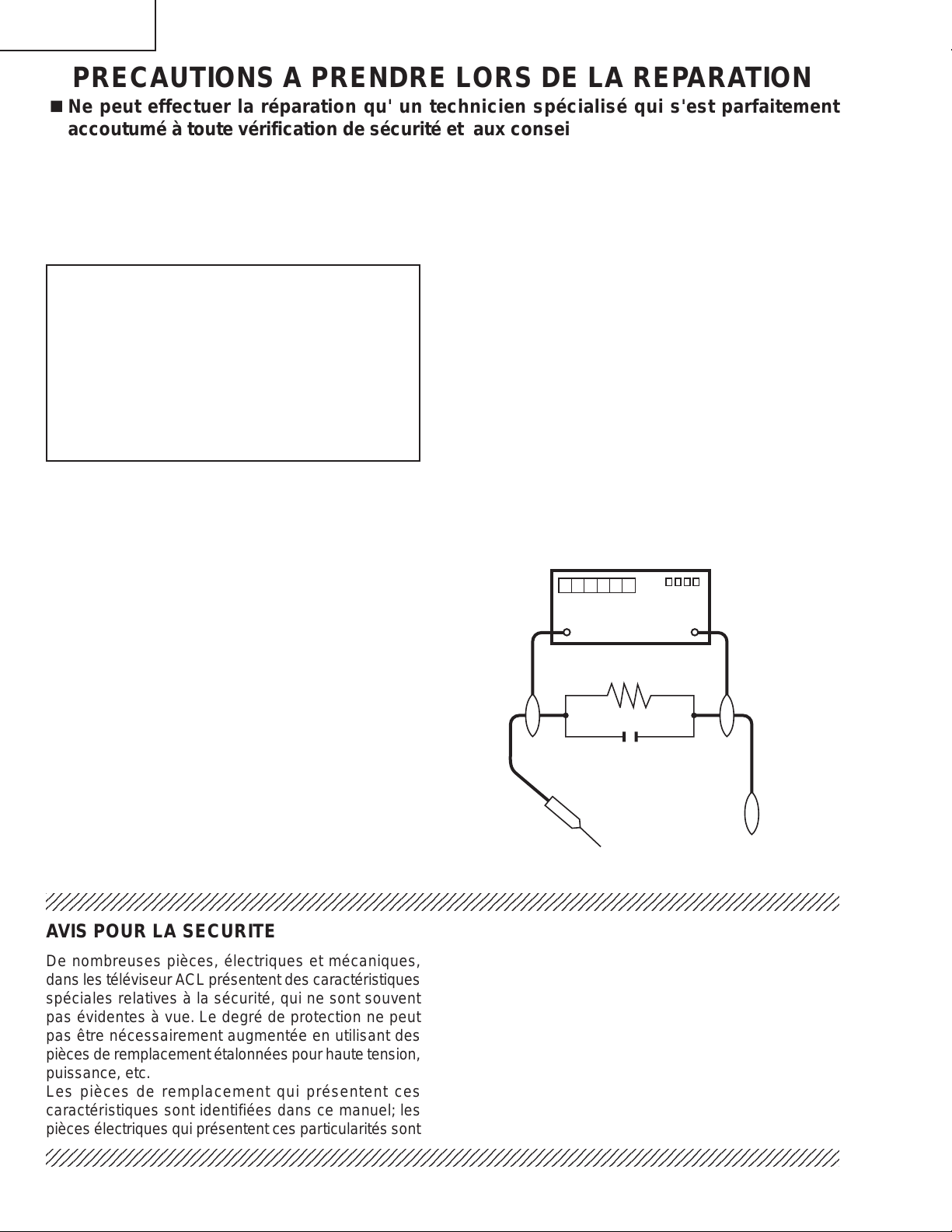
3. S'assurer qu'il n'y ait pas de danger d'électrocution en
vérifiant la fuite de courant, de la facon suivante:
• Brancher le cordon d'alimentation directem-ent à une
0.15 µF
SONDE D'ESSAI
prise de courant de 120V. (Ne pas utiliser de
transformateur d'isolation pour cet essai).
• A l'aide de deux fils à pinces, brancher une résistance
de 1.5 kΩ 10 watts en parallèle avec un condensateur
234567890123456789012345678901212345678901234567890123456789012123456789012345678901234567890121
AUX PIECES
METALLIQUES
EXPOSEES
BRANCHER A UNE
TERRE CONNUE
AVIS POUR LA SECURITE
De nombreuses pièces, électriques et mécaniques,
dans les téléviseur ACL présentent des caractéristiques
spéciales relatives à la sécurité, qui ne sont souvent
pas évidentes à vue. Le degré de protection ne peut
pas être nécessairement augmentée en utilisant des
pièces de remplacement étalonnées pour haute tension,
puissance, etc.
Les pièces de remplacement qui présentent ces
caractéristiques sont identifiées dans ce manuel; les
pièces électriques qui présentent ces particularités sont
234567890123456789012345678901212345678901234567890123456789012123456789012345678901234567890121
234567890123456789012345678901212345678901234567890123456789012123456789012345678901234567890121
identifiées par la marque " å " et hachurées dans la
liste des pièces de remplacement
schématiques
.
et les
diagrammes
Pour assurer la protection, ces pièces doivent être
identiques à celles utilisées dans le circuit d'or igine.
L'utilisation de pièces qui n'ont pas les mêmes
caractéristiques que les pièces recommandées par
l'usine, indiquées dans ce manuel, peut provoquer des
électrocutions, incendies, radiations X ou autres
accidents.
6
Page 7
LC-26D5U
LC-32D5U
LC-37D5U
Precautions for using lead-free solder
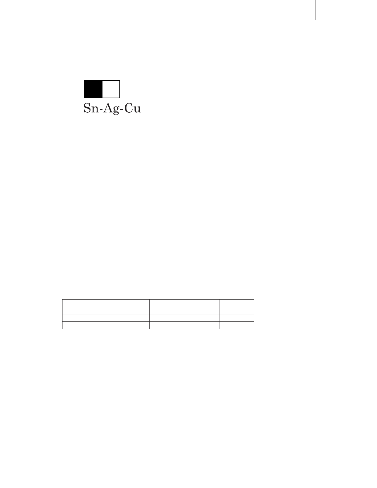
1 Employing lead-free solder
"PWBs" of this model employs lead-free solder. The LF symbol indicates lead-free solder, and is attached on the
PWBs and service manuals. The alphabetical character following LF shows the type of lead-free solder.
Example:
L Fa
Indicates lead-free solder of tin, silver and copper.
2 Using lead-free wire solder
When fixing the PWB soldered with the lead-free solder, apply lead-free wire solder. Repairing with conventional
lead wire solder may cause damage or accident due to cracks.
As the melting point of lead-free solder (Sn-Ag-Cu) is higher than the lead wire solder by 40°C, we recommend
you to use a dedicated soldering bit, if you are not familiar with how to obtain lead-free wire solder or soldering bit,
contact our service station or ser vice branch in your area.
3 Soldering
As the melting point of lead-free solder (Sn-Ag-Cu) is about 220°C which is higher than the conventional lead
solder by 40°C, and as it has poor solder wettability, you may be apt to keep the soldering bit in contact with the
PWB for extended period of time. However, Since the land may be peeled off or the maximum heat-resistance
temperature of parts may be exceeded, remov e the bit from the PWB as soon as you confirm the steady soldering
condition.
Lead-free solder contains more tin, and the end of the soldering bit may be easily corroded. Make sure to turn on
and off the power of the bit as required.
If a different type of solder stays on the tip of the soldering bit, it is allo y ed with lead-free solder. Clean the bit after
every use of it.
When the tip of the soldering bit is blackened during use, file it with steel wool or fine sandpaper.
Be careful when replacing parts with polarity indication on the PWB silk.
Lead-free wire solder for servicing
Part No, ★ Description Code
ZHNDAi123250E J φ0.3mm 250g(1roll) BL
ZHNDAi126500E J φ0.6mm 500g(1roll) BK
ZHNDAi12801KE J φ1.0mm 1kg(1roll) BM
7
Page 8
LC-26D5U
LC-32D5U
LC-37D5U
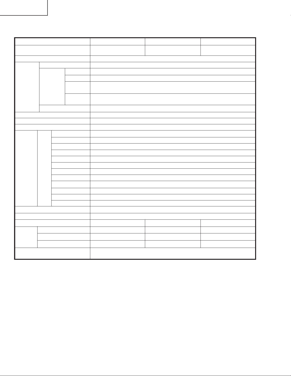
SPECIFICATIONS
Item Model: LC-37D5U
LCD panel 37" Advanced Super
View & BLACK TFT LCD
Number of dots 3,147,264 dots (1366 768 3 dots)
TV
Function
Brightness 450 cd/m
Viewing angles H : 170° V : 170°
Audio out 10W 2
Terminals
OSD language English/French/Spanish
Power Requirement
Power Consumption
Weight
Accessories Operation manual ( 1), Remote control unit ( 1), AC cord ( 1), “AAA” size
TV-standard (CCIR)
Receiving
Channel
Audio multiplex BTSC System
Rear
INPUT 1
INPUT 2
INPUT 3
INPUT 4
INPUT 5 Audio in, DVI-I in with HDCP
ANALOG ANTENNA
DIGITAL ANTENNA
MONITOR/REC OUT
G-LINK
DIGITAL AUDIO OUTPUT
i.LINK
CableCARD slot
TV only
Stand
VHF/UHF
CATV 1-125ch
Digital Terrestrial
Broadcast (8VSB)
Digital cable
(64/256 QAM)
American TV Standard ATSC/NTSC System
VHF 2-13ch, UHF 14-69ch
2-69ch
1-135ch
2
×
AV in, COMPONENT in
AV in, COMPONENT in
S-VIDEO in, AV in
HDMI in (Type-A) with HDCP
75 Unbalance, F Type for VHF/UHF/CATV in 1
Ω
Ω
75 Unbalance, F Type 2 (for Digital Air 1/Digital Cable in 1)
S-VIDEO out, AV out
Ø 3.5mm jack
Optical Digital audio output 1 (PCM/Dolby Digital)
IEEE1394 2 with DTCP
68 pin PCMCIA 1
AC 120 V, 60 Hz
195 W
45.4 lbs./20.6 kg
10.8 lbs./4.9 kg
56.2 lbs./25.5 kgTV with stand
battery ( 2), Cable clamp ( 1), G-LINK cable ( 1), Cable tie ( 1)
×
×
×
×××
Model: LC-32D5U Model: LC-26D5U
32" Advanced Super
View & BLACK TFT LCD
×
×
×
×
155 W 130 W
39 lbs./17.7 kg 29.8 lbs./13.5 kg
8.4 lbs./3.8 kg 7.7 lbs./3.5 kg
47.4 lbs./21.5 kg 37.5 lbs./17 kg
××
26" Advanced Super
View & BLACK TFT LCD
××××
• As part of policy of continuous improvement, SHARP reserves the right to make design and specification changes for product improvement
without prior notice. The performance specification figures indicated are nominal values of production units. There may be some
deviations from these values in individual units.
8
Page 9
OPERATION MANUAL
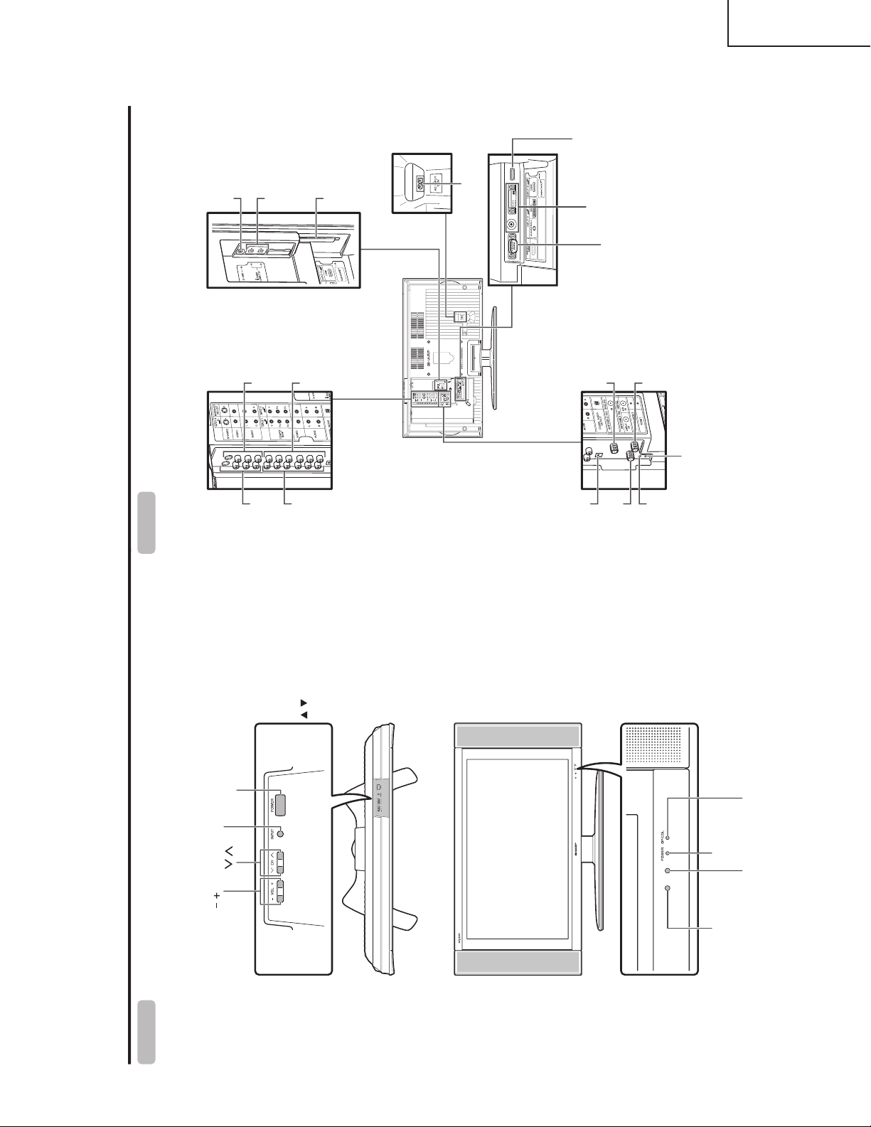
Part names
TV (Front)
POWER indicatorOPC sensor
POWER button
INPUT button*
Volume buttons (VOL / )
Channel
buttons**
(CH / )
Remote control sensor
OPC/DL indicator
* INPUT button works as
ENTER in TV Guide On
Screen
** Channel buttons work as
/ in TV Guide On
Screen
TV (Rear)
* Press RESET if the TV cannot return to its original state after performing various operations.
• AV MODE resets to DYNAMIC (Fixed)
• TV channel returns to initial channel (Air:2ch, Cable:1 or 2ch)
• Audio setting initializes
• Dolby Virtual resets to off
• Image position initializes
**Press SYSTEM RESET if the TV does not operate after starting up.
RESET*
INPUT 3
terminals
SYSTEM
RESET**
ANALOG IN
terminal
AC INPUT terminal
RS-232C terminal
INPUT 2 terminals
INPUT 1
terminals
INPUT 5 terminals
INPUT 4 terminal
MONITOR OUT/
REC OUT terminals
i.LINK terminals
CableCARD™ slot
DIGITAL AUDIO
OUTPUT terminal
G-LINK terminal
DIGITAL AIR IN
terminal
DIGITAL CABLE
IN terminal
LC-26D5U
LC-32D5U
LC-37D5U
9
Page 10
LC-26D5U
P Using external equipmentart names
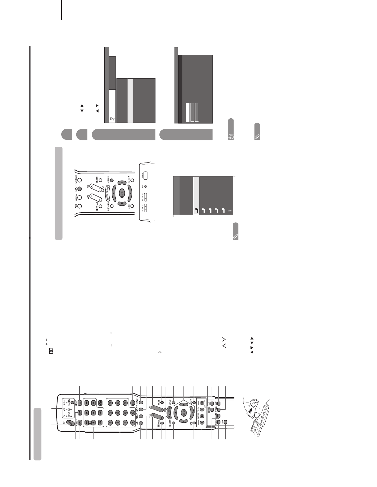
Remote control unit
2
318
19
20
21
22
23
24
25
26
27
28
29
30
31
32
117
4
5
6
7
8
9
11
12
13
14
15
16
10
6AIR: Receives air signal.
7 CABLE: Receives cable signal.
8VOL /: Sets the volume.
9
Virtual: Selects Virtual Dolby Surround settings.
10 INFO: Displays the program information screen.
11 RECORD: Records the program to equipment (capable
of recording).
In TV Guide On Screen, initiates the recording process.
12 EXIT: Turns off the menu screen and TV Guide On
Screen.
13 FAVORITE CH
A, B, C, D: Selects four preset favorite channels in four
different categories.
While watching, you can toggle the selected channels
by pressing A, B, C and D.
DAY /DAY : In TV Guide On Screen, moves forward
or backward in 24 hour increments in the listing grid.
14 AUDIO: Selects the MTS/SAP or the audio mode during
multi-channel audio broadcasts.
15 SLEEP: Sets the sleep timer.
16 i.LINK: Displays the i.LINK panel.
17 FUNCTION: Switches the remote control for TV, CBL/
SAT, VCR, DVD and AUDIO operation. Indicator lights
up for the current mode.
* To enter the code registration mode, you need to press
FUNCTION and DISPLAY at the same time.
18
: When pressed all buttons on the remote control unit
will light. The lighting will turn off if no operations are
performed within about 5 seconds. This button is used
for performing operations in low-light situations.
19 VIEW MODE: Selects the screen size.
20 ENT: Enters a channel selection when choosing with
the 0-9 buttons.
21 FLASHBACK: Returns to the previous channel or
external input mode.
22 INPUT: Selects a Liquid Crystal Television input source.
(TV, CableBox, INPUT 1, INPUT 2, INPUT 3, INPUT 4,
INPUT 5, i.LINK)
If the CableBox is set up in the TV Guide On Screen
setting menu, the CableBox option appears.
23 CH / : Selects the channel. In the TV Guide On
Screen, moves one page up or one page down in the
LISTINGS grid.
24 MUTE: Mutes the sound.
25 TV GUIDE: Displays TV Guide On Screen.
26 MENU: Displays the menu screen.
27 ////ENTER: Selects a desired item on the
screen.
28 RETURN: Returns to the previous menu screen.
29 FREEZE: Sets the still image. Press again to return to
normal screen.
30 CC: Displays captions when receiving closed-caption
signals.
31 EDIT: Registers favorite channel.
32 AV MODE: Selects an audio or video setting.
(AV mode: STANDARD, MOVIE, GAME,
USER, DYNAMIC (Fixed), DYNAMIC. PC mode:
STANDARD, USER.)
1TV POWER: Switches the Liquid Crystal Television
power on or enters Standby mode.
2 DISPLAY: Displays the channel information.
3 SOURCE POWER: Turns the power of the external
equipment on and off.
4 External equipment operational buttons: Operates
the external equipment.
50 – 9/• (DOT): Sets the channel.
You can connect many types of external equipment to your TV, like a DVD player, VCR, Digital TV tuner, PC,
HDMI equipment, game console and camcorder. To view external source images, select the input source from
INPUT on the remote control unit or on the TV.
CAUTION
• To protect all equipment, always turn off the TV before
connecting to a DVD player, VCR, Digital TV tuner, PC,
HDMI equipment, game console, camcorder or other
external equipment.
NOTE
• Please refer to the relevant operation manual (DVD player,
PC, etc.) carefully before making connections.
• Each time INPUT is pressed, the input source toggles.
• Refer to your exter nal equipment operation manual for
the signal type.
Displaying an external equipment image
Explanation here is for the setting when connecting
DVD to INPUT1 terminal.
To watch a DVD image, select “INPUT1” from “INPUT
SOURCE” menu using INPUT on the remote control
unit or on the TV.
INPUT SOURCE
TV
CableBox [TV]
INPUT1
INPUT2
INPUT3
INPUT4
INPUT5INPUT5
i.LINK
1
MENU
[
Option
...
Input Select
]
Auto
COMPONENT
VIDEO
For INPUT1 signal
Select the desired signal type.
The setting is stored and can be selected on the
“INPUT SOURCE” menu.
Press MENU and the MENU screen displays.
2
3
Press / to select “Input Select”, and then
press ENTER.
4
Press / to select “Option”.
MENU
[
Option
...
Input Select
]
Option
Input Select
Digital Noise Reduction
Output Select
Audio Only
Quick Shoot
[Fixed]
[Auto]
[Low]
[Off]
Caption Setup
Program Title Display
[No]
NOTE
• If the image does not come in clearly, you may need to
change the input signal type setting on the “Input Select”
menu.
Selecting the INPUT signal
LC-32D5U
LC-37D5U
10
Page 11
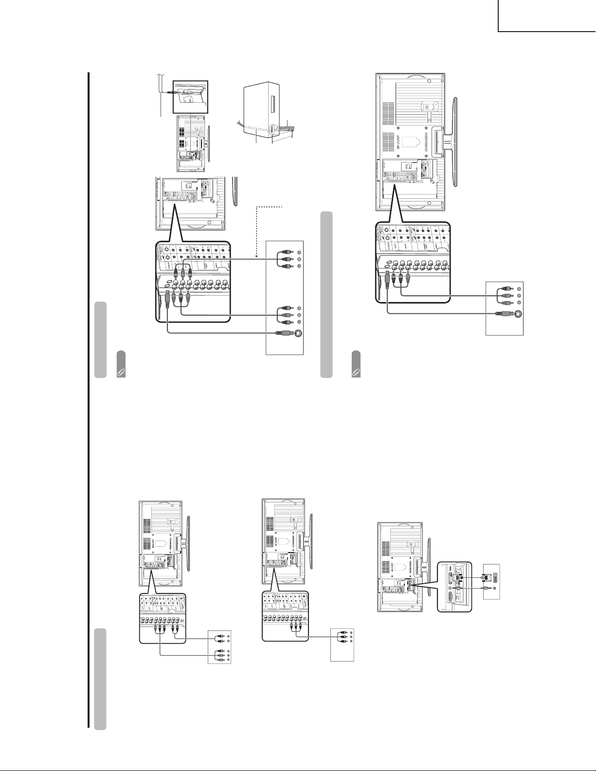
Using external equipment
Connecting a DVD player
You can use the INPUT 1, INPUT 2, INPUT 4 or INPUT 5 terminals when connecting to a DVD player and other
audiovisual equipment.
DVD player
Component
video cable
(commercially
available)
Audio cable
(commercially available)
AV cable (commercially
available)
DVD player
ø 3.5 mm stereo minijack cable
(commercially available)
DVI cable (Commercially available)
When using component cable.
When using composite cable.
When using DVI cable. (INPUT 5)
DVD player
VCR
This connection is necessary
when using TV Guide On
Screen’s recording function.
(commercially available)
Connecting a VCR
You can use the INPUT 3 terminal when connecting a VCR and other audiovisual equipment.
S-video cable
(commercially
available)
NOTE
• The S-video terminal has priority over the video ter minals.
• The G-LINK cable connection is necessary if you want to use the recording features of the TV Guide On Screen system
with your VCR.
(INPUT)(OUTPUT)
AV cable
(commercially
available)
G-LINK cable
G-LINK
cable
This end is connected
to the TV.
1 inch
VCR
G-LINK wand
Game console/Camcorder
Connecting a game console or camcorder
A game console, camcorder and some other audiovisual equipment are conveniently connected using the
INPUT 3 terminals.
AV cable
(commercially available)
S-video cable
(commercially
available)
NOTE
• The S-video ter minal has priority over the video terminals.
LC-26D5U
LC-32D5U
LC-37D5U
11
Page 12
LC-26D5U
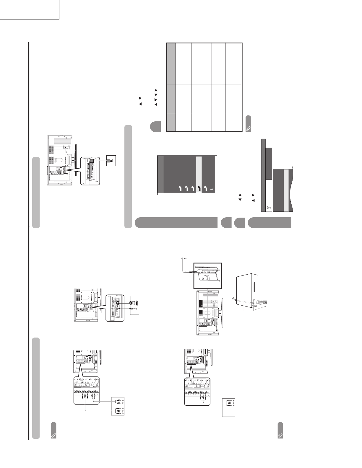
Using external equipment
Connecting a Digital TV STB (Air or Cable)
You can use the INPUT 1, INPUT 2, INPUT 4 or INPUT 5 terminals when connecting a Digital TV STB (Air or
Cable) and other audiovisual equipment.
NOTE
• If your cable-TV company has CableCARD available, you can also use the CableCARD to receive
HDTV programs.
Digital TV STB
Component video
cable
(commercially
available)
Audio cable
(commercially available)
AV cable
(commercially available)
Digital TV STB
Digital TV STB
ø 3.5 mm stereo
minijack cable
(commercially
available)
DVI cable
(Commercially available)
When using component cable.
When using composite cable.
When using DVI cable. (INPUT 5)
G-LINK cable
Cable box connection
(for TV Guide On Screen)
G-LINK
cable
This end is connected
to the TV.
1 inch
Cable Box
G-LINK wand
NOTE
• To receive TV program listings in the TV Guide On Screen system, please connect your cable box
using this input, marked “VIDEO”. Do not connect the cable box to the “COMPONENT” video as you
will not receive any TV program listings.
Connecting HDMI equipment
Please use the INPUT 4 terminal when connecting HDMI equipment.
HDMI equipment
HDMI cable
(Commercially available)
Displaying an image from HDMI equipment
To watch an HDMI equipment image, select
“INPUT4” from “INPUT SOURCE” menu
using INPUT on the remote control unit or
on the TV.
INPUT SOURCE
TV
CableBox [TV]
INPUT1
INPUT2
INPUT3
INPUT4
INPUT5INPUT5
i.LINK
1
Press MENU and the MENU screen displays.
2
3
Press / to select “HDMI Setup”, and then
press ENTER.
4
Press / to select “Option”.
MENU
[
Option
...
HDMI Setup
]
Option
Digital Noise Reduction
Audio Only
HDMI Setup
[Low]
Press / to select the desired item and
press ENTER.
Press / / / to select the desired setting
and press ENTER.
6
NOTE
• Refer to your external equipment operation manual for
the signal type.
Selectable items
Auto/RGB/YCbCr
4:4:4/YCbCr 4:2:2
Auto/ITU601/
ITU709
Standard/
Out of Standard
Enable/Disable
HDMI Setup
items
Signal
Type
Color
Matrix
Dynamic
Range
Auto View
Description
Select the signal type from
an HDMI terminal. Unless
the image quality looks
obviously poor, select Auto.
Select the internal color
space conversion method
when an RGB signal is
input. Normally, select
Auto.
Select the signal amplitude
range. Normally, select
Standard.
Set whether or not to use
VIEW MODE based on
signal recognition,
including an HDMI signal.
LC-32D5U
LC-37D5U
12
Page 13
LC-26D5U
Using external equipment Appendix
Connecting a PC
Use the INPUT 5 terminal to connect a PC.
PC with DVI terminal
ø 3.5 mm stereo minijack cable
(commercially available)
DVI cable (Commercially available)
ø 3.5 mm stereo minijack cable
(commercially available)
PC with analog RGB terminal
RGB/DVI conversion cable
(Commercially available)
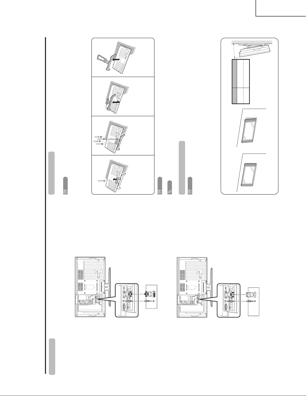
Removing the stand
Before detaching (or attaching) stand, unplug the AC cord from the AC input terminal.
CAUTION
• Do not remove the stand from the TV unless using an optional wall mount bracket to mount it.
Before attaching/detaching stand
• Before performing work make sure to turn off the TV.
• Before performing work spread cushioning over the base area to lay the TV on. This will prevent it from being
damaged.
NOTE
• To attach the stand, perform the above steps in reverse order.
2
Unfasten the four screws
used to secure the stand in
place.
1
Unfasten the screw used to
secure the bracket in place.
Setting the TV on the wall
CAUTION
• Installing the Liquid Crystal Television requires special skill that should only be performed by qualified service
personnel. Customers should not attempt to do the work themselves. SHARP bears no responsibility f or improper
mounting or mounting that results in accident or injury.
Using an optional bracket to mount the TV
• You can ask a qualified service professional about using an optional AN-37AG2 bracket to mount the TV to
the wall. The AN-37AG2 is compatible with the LC-37D5U and LC-32D5U only.
• Carefully read the instructions that come with the bracket before beginning work.
Hanging on the wall
AN-37AG2 wall mount bracket. (See the bracket instructions
for details.)
About setting the TV angle
CAUTION
• Do not remove the stand from the TV unless using an optional bracket to mount it.
Vertical mounting Angular mounting
3
Detach the stand from the
TV.
(Hold the stand so it will not
drop from the edge of the
base area.)
Angle of TV
LC-37D5U
5˚
LC-32D5U 10˚
(LC-37/32D5U)
Detach the stand from the
TV.
(Hold the stand so it will not
drop from the edge of the
base area.)
(LC-26D5U)
LC-32D5U
LC-37D5U
13
Page 14
LC-26D5U
Appendix
PC compatibility chart
Apple and Macintosh are registered trademarks
of Apple Computer, Inc.
DDC is a registered trademark of Video Electronics
Standards Association.
Power Management is a registered trademark of
Sun Microsystems, Inc.
VGA and XGA are registered trademarks of
International Business Machines Co., Inc.
PC/MAC Resolution
Horizontal Frequency
Vertical Frequency
VESA Standard
PC
31.5 kHz
37.9 kHz
31.5 kHz
37.9 kHz
31.5 kHz
37.9 kHz
37.5 kHz
43.3 kHz
31.5 kHz
35.1 kHz
37.9 kHz
48.1 kHz
46.9 kHz
53.7 kHz
48.4 kHz
56.5 kHz
60.0 kHz
68.7 kHz
45.0 kHz
48.1 kHz
64.0 kHz
34.9 kHz
49.7 kHz
60.2 kHz
640 x 400
720 x 400
VGA
640 x 480
WVGA 848 x 480
SVGA 800 x 600
1024 x 768XGA
1280 x 720
WXGA
1280 x 768
SXGA
1280 x 1024
VGA
640 x 480
MAC13"
XGA
1024 x 768
MAC19"
SVGA
832 x 624
MAC16"
60 Hz
85 Hz
60 Hz
85 Hz
60 Hz
72 Hz
75 Hz
85 Hz
60 Hz
56 Hz
60 Hz
72 Hz
75 Hz
85 Hz
60 Hz
70 Hz
75 Hz
85 Hz
60 Hz
60 Hz
60 Hz
67 Hz
75 Hz
75 Hz
O
O
O
O
O
O
O
O
O
O
O
O
O
O
O
O
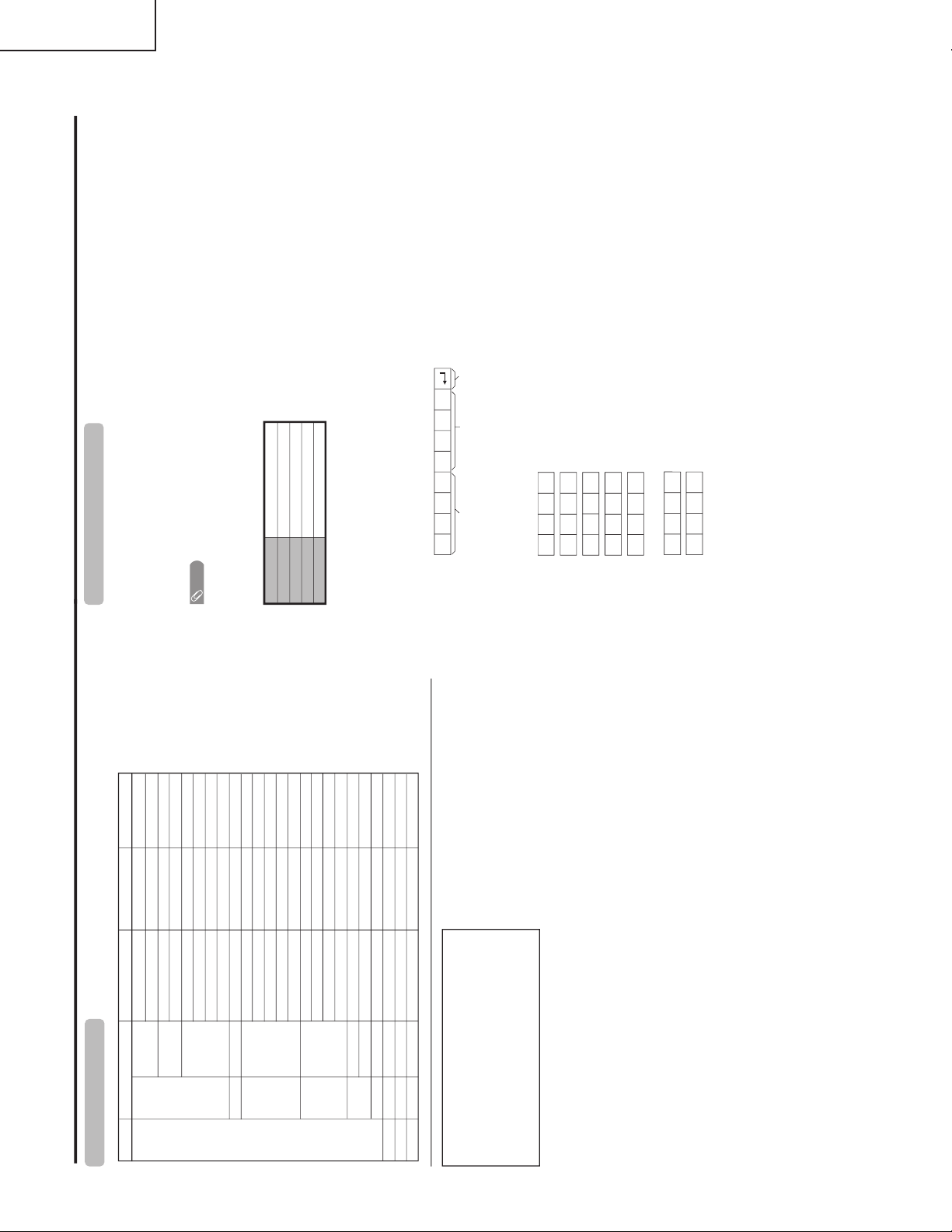
RS-232C port specifications
Return codeCommand 4-digits Parameter 4-digits
PC Control of the TV
• When a program is set, the TV can be controlled from the PC using the RS-232C terminal.
The input signal (PC/AV) can be selected, the volume can be adjusted and various other adjustments and
settings can be made, enabling automatic programmed playing.
•
Attach an RS-232C cable cross-type (commercially available) to the supplied Din/D-Sub RS-232C for the
connections.
NOTE
• This operation system should be used by a person who is accustomed to using computers.
Communication conditions
Set the RS-232C communications settings on the PC to match the TV’s communications conditions.
The TV’s communications settings are as follows:
Baud rate:
Parity bit:
Data length:
Stop bit:
Flow control:
9,600 bps
8 bits
None
1 bit
None
Command format
Communication procedure
Send the control commands from the PC via the RS-232C connector.
The TV operates according to the received command and sends a response message to the PC.
Do not send multiple commands at the same time. Wait until the PC receives the OK response before sending
the next command.
Eight ASCII codes CR
Command 4-digits:Command. The text of four characters.
Parameter 4-digits:Parameter 0 – 9, x, blank, ?
Parameter
Input the parameter values, aligning left, and fill with blank(s) for the remainder. (Be sure that 4 values are input for the
parameter.)
When the input parameter is not within an adjustable range, “ERR” returns. (Refer to “Response code format”.)
Any numerical value can replace the “x” on the table.
When “?” is input for some commands, the present setting value responds.
C1 C2 C3 C4 P1 P2 P3 P4
0055
100
30
0009
0
????
?
+
-
LC-32D5U
LC-37D5U
14
Page 15

LC-26D5U
Appendix Basic adjustment settings
Command table
• Commands not indicated here are not guaranteed to operate.
CONTROL ITEM COMMAND
PARAMETER
CONTROL CONTENTS
POWER SETTING It shifts to standby.
It input-switches by the toggle. (It is the same as an input change key)
It input-switches to TV. (A channel remains as it is. (Last memory))
It input-switches to INPUT1~INPUT5.
It input-switches to i.LINK.
An input change is also included.
Although it can choose now, it is toggle operation in inside.
Although it can choose now, it is toggle operation in inside.
(Toggle)
Input terminal number (1–5)
AUTO
VIDEO
COMPONENT
DIGITAL PC
ANALOG PC
DIGITAL AV
ANALOG AV
(Toggle)
STANDARD
MOVIE
USER
GAME
DYNAMIC (Fixed)
DYNAMIC
Volume (0–60)
AV mode. ( 10)
PC mode. (0–180)
AV mode. ( 20)
PC mode. (0–100)
Only PC mode. (0–180)
Only PC mode. (0–40)
(Toggle) [AV]
An input change is included if it is not TV display.
In Air, 2–69ch is effective.
In Cable, 1–125ch is effective.
If it is not TV display, it will input-switch to TV. (same function as CH )
If it is not TV display, it will input-switch to TV. (same function as CH )
Toggle operation of a closed caption.
(Toggle)
Side Bar [AV]
S.Stretch [AV]
Zoom [AV]
Stretch [AV]
Normal [PC]
Zoom [PC]
Stretch [PC]
Dot by Dot [PC]OnOff
OFF
OFF TIMER – 30 MIN.
The channel number of TV
The channel number of TV 1
The channel number of TV 1
(Toggle)
(1–125)
AUTO
POWR
ITGD
ITVD
IAVD
INP1
INP5
INPUT SELECTION A TOGGLE
i.LINK
INPUT SELECTION B
AV MODE SELECTION
VOLUME
POSITION
VIEWMODE
Dolby Virtual
SLEEP TIMER
CHANNEL
Air/Cable SELECT
CC
DIRECT
(ANALOG)
(DIGITAL)
CH UP
CH DOWN
CHANNEL
H-POSITIONH-POSITION
V-POSITION
CLOCK
PHASE
INPUT 1
INPUT 5
AVMD
VOLM
HPOS
VPOS
CLCK
PHSE
ACDV
OFTM
DCCH
CHUP
CHDW
CLCP
WIDE
0
x
x
*
0
567
8
1
2
0
*****
0
0
*
x
x
x
112
012345678
*
*
12345
6
*
_
_
_
_
___
_
_________
*****
*
*
_____
___
_
_
_
_______
*
_
_
_
_
___
_
_________
*
***
*
*
_
_____
___
_
_
_
_______
_
DIGITAL Air (Two-Part numbers, 2-digit plus 2-digit)(0101-9999)
(0-999)
(0-999)
(0-9999)
(0-6383)
DIGITAL Cable (Two-Part numbers, 3-digit plus 3-digit)
DIGITAL Cable (Two-Part numbers, 3-digit plus 3-digit)
Front half of DIGITAL CABLE CHANNEL NO. (Designate major channel)
Rear half of DIGITAL CABLE CHANNEL NO. (Designate minor channel)
DIRECT
CHANNEL
DA2P * * * *
DC2U * * * _
DC2 L * * * _
DIGITAL Cable (One-Part numbers, 5-digit, less than 10,000)
DC1 0 * * * *
DIGITAL Cable (One-Part numbers, 5-digit, more than 10,000)
DC1 1 * * * *
_
_
AIR CABLE AIR(Toggle)ACSL 0 __ _
AIR1___
CABLE2___
_
_
(Toggle)
AUDIO SELECTION
ACHAx _ __
_
_
OFF TIMER – 60 MIN.
OFF TIMER – 90 MIN.
2
3
_
_
_
_
_
_
OFF TIMER – 120 MIN. 4___
_
_
(Toggle)OnOff
MUTE
MUT E 0
1
2
___
___
___
_________
_
INPUT5: AV mode. ( 90)***_
___
_
INPUT5: AV mode. ( 50)
***
_
_
_
___
_
LINKx___
_
___
_
_
_
AUTO
VIDEO
COMPONENT
AUTOINP2
INPUT 2
012
___
___
___
_______
TV
INPUT1-5
NOTE
• If an underbar (_) appears in the parameter column, enter a space.
• If an asterisk (*) appears, enter a value in the range indicated in brackets under CONTROL CONTENTS.
• As long as that from which the parameter ( ) in the table is a numerical value, it may write anything.
Return code (0DH)
Response code format
Normal response
Problem response (communication error or incorrect command)
Return code (0DH)
OK
ERR
×
±
±
±
±
+
-
AV input mode menu items
List of AV menu items to help you with operations
OPC
Backlight
Contrast
Brightness
Color
Tint
Sharpness
Advanced
C.M.S.
Color Temp.
Black
3D-Y/C
Monochrome
Film Mode
I/P Setting
Picture
No Signal Off
No Operation Off
EZ Setup
CH Setup
Antenna Setup-DIGITAL
Input Label
Parental CTRL
Position
Picture Flip
Standby Mode
Language
Treble
Bass
Balance
Dolby Virtual
Audio Only
Digital Noise Reduction
HDMI Setup
Input Select
Output Select
Quick Shoot
Caption Setup
Program Title Display
Audio
Power Control
Setup
Option
CableCARD Menu
Video Setup
Audio Setup
i.LINK Setup
Digital Setup
Power Management
Input Signal
Auto Sync.
Input Label
Fine Sync.
Picture Flip
Standby Mode
Language
Power Control
Setup
Option
Audio Only
Input Select
Output Select
Quick Shoot
i.LINK Setup
Digital Setup
*PC input mode menu items
List of PC menu items to help you with
operations
*When INPUT5 is set to PC.
OPC
Backlight
Contrast
Brightness
Red
Green
Blue
Advanced
C.M.S.
Picture
Treble
Bass
Balance
Dolby Virtual
Audio
LC-32D5U
LC-37D5U
15
Page 16

LC-26D5U
31
32
50)
LC-32D5U
LC-37D5U
DIMENSIONS (LC-26D5U)
LC-26D5U
418)
(
64
/
497)
(
29
16
/
9
79) 16
(
64
/
7
Unit: inch/(mm)
3
22
/
64
(
560)
3
/8 (
848)
33
23
22
/
64
(
567.9)
320.6)
(
8
/
5
12
15
3
/
16
(
100)
289)
(
8
/
3
11
1
31
2
/8 (
54)4
/
64
(
114)
482)
(
32
/
31
18
35
10
/
64
(
268)
50) 3
50)
100) 19
(
(
(
32
32
16
/
/
/
31
31
15
1
1
3
16
Page 17

DIMENSIONS (LC-32/37D5U)
LC-26D5U
LC-32D5U
LC-37D5U
LC-37D5U
15
7
647)
(
32
/
25
200)
(
8
/
7
1
11
3
562)3
(
8
/
22
85)
(
32
/
104)
(
32
/
4
Unit: inch/(mm)
2613/
32
(
671)
1
/2 (
1105)
43
3
32
/8 (
822.6)
463.8)
(
4
/
1
18
7
7
/8 (
200)
367.8)
(
64
/
31
14
1
31
/8 (
105) 4
/
64
(
4
114)
3
12
/
64
(
306)
LC-32D5U
3
7
578)
(
4
/
22
200)
(
8
/
7
13
11
33
493)3
(
32
/
19
85)
(
32
/
115)
(
64
/
4
247/8 (
632)
37
/
64
(
980)
38
37
27
/
64
(
700.4)
395.1)
(
64
/
35
15
7
7
/8 (
200)
333.5)
(
8
/
1
13
35
31
3
/
64
(
90) 4
/
64
(
114)
3
11
/8 (
289)
17
Page 18

LC-26D5U
LC-32D5U
LC-37D5U
REMOVING OF MAJOR PARTS (LC-26D5U/32D5U)
1. Remove the 4 lock screws 1 from the stand, and detach the stand.
2. Detach the Terminal Cover.2
3. Detach the SD Card Cover and PC Card Cover.3
4. Remove the 17 lock screws 4 from the Rear Cabinet, and detach the Rear Cabinet. (only for LC-26D5U)
4. Remove the 25 lock screws 4 from the Rear Cabinet, and detach the Rear Cabinet. (only for LC-32D5U)
LC-26D5U
PC Card Cover
Terminal Cover
1
2
SD Card Cover
3
3
4
Stand
LC-32D5U
Front Cabinet
4
Rear Cabinet
4
PC Card Cover
Terminal Cover
1
SD Card Cover
3
3
2
4
18
Front Cabinet
4
4
Stand
Rear Cabinet
4
Page 19

5. Remove the 4 (LC-26D5U) / 7 (LC-32D5U) lock screws 5 and detach the Center Angle.
6. Remove the KEY PWB.
6-1. Remove the 2 lock screws 6 from the Top Control Cover.
6-2. Remove the 3 lock screws 7 from the KEY PWB.
7. Remove the 5 lock screws 8 and detach the LCD PWB Shield.
8. Remove the 4 lock screws 9 and detach the Main Shield A.
LC-26D5U
LC-32D5U
LC-37D5U
6
KEY PWB
Top Control
Cover
P151
LC-26D5U
5
7
LCD PWB Angle
LC-32D5U
5
Center AngleCenter Angle
8
P2002
9
Main Shield A
19
Page 20

LC-26D5U
LC-32D5U
LC-37D5U
9. Disconnect all the connectors from all the PWBs.
CN7601
CN7602
CN7603
CN7604
CN7605
CN7606
CN7607
CN7608
P203
P1105
P3805
P3804
P2501
P3101
P101
SC3202
SC3201
P7704
P5703
P2004
SC4651
SC4601
SC3202
SC3201
P2006
P1802
P8301
P9201
SC9601
P1501
P1804
P1803
SC4652
P2003
SC3200
10. Remove the 5 lock screws 0 and detach the Main Shield B.
11. Remove the 4 lock screws q and detach the Digital PWB
12. Remove the 4 lock screws w and detach the Jack Cover C.
13. Detach the 2 Speaker Box.e
11
Digital PWB
SC2101
SC2102
P7707
CN707
CN705
P7705
CN706
CN704
CN703
CN7501
CN7502
P204
CN7503
CN7504
CN7505
CN7506
CN7507
CN7508
CN7509
10
Main Shield B
12
Jack Cover C
13 13
Speaker Box (L)Speaker Box (R)
20
Page 21

14. Remove the 6 lock screws r. Detach the Main PWB and Main Shield C.
15. Remove the AV PWB.
15-1. Remove the 3 lock screws t, 2 screws y, 2 screws u(LC-26D5U only) and detach the AV PWB.
15-2. Remove the 1 lock screw i and detach the Jack Cover B.
15-3. Remove the 4 lock screws o and detach the Jack Cover A.
16. Remove the 1 lock screw p and detach the LCD Controller PWB. Detach the Radiation Shields.
LC-26D5U only
17
15
LC-26D5U
LC-32D5U
LC-37D5U
19
Jack Cover A
Jack Cover B
Radiation Shield
16
18
AV PWB
LCD Controller PWB
Radiation
Shield
20
Main Shield C
21
Main PWB
14
Page 22

LC-26D5U
LC-32D5U
LC-37D5U
17. Remove the 6 lock screws a and detach the Power PWB.
18. Remove the INVERTER-GND PWB.
LC-26D5U: Remove the 3 lock screws s and detach the INVERTER-GND PWB.
LC-32D5U: Remove the 6 lock screws s and detach the INVERTER-GND PWB.
19. Remove the INVERTER PWB.
LC-26D5U: Remove the 4 lock screws d and detach the INVERTER PWB.
LC-32D5U: Remove the 8 lock screws d and detach the INVERTER A and B PWB.
20. Remove the 2 lock screws 24 and detach the R/C LED PWB.
21. Remove the 4 (LC-26D5U) / 5 (LC-32D5U) lock screws 25 and detach the Fixing Angle.
22. Remove the 2 lock screws 26 (LC-32D5U only) and detach the LCD Panel Ass'y.
21
Power PWB
LC-32D5U
25
LC-26D5U
LC-32D5U
22
LC-26D5U
22
26
Fixing Angle
23
LC-32D5U
23
INVERTER GND PWB
R/C, LED
PWB
24
25
LC-26D5U
Fixing
Angle
25
INVERTER
PWB
LCD Panel Ass’y
INVERTER
A and B PWB
22
Page 23

LC-26D5U
LC-32D5U
LC-37D5U
23. Remove the 4 lock screws 27 from the LCD Panel Unit, and detach the LCD Panel Unit.
24. Detach the sheet spacer-S and sheet spacer-B (LC-26D5U).
Detach the sheet spacer-S and sheet spacer-L (LC-32D5U).
25. Detach the Diffusion and Reflection/Deflection Sheets and Diffusion Panel.
26. Remove the 2 (LC-26D5U) / 6 (LC-32D5U) lock screws 28 from the Lamp Holder Ass'y (top), and detach the
Lamp Holer (top).
27. Remove the Fluorescent Lamps.
Lamp Holder (Bottom)
Lamp Holder Ass’y (Top)
Back Shield
Sheet Spacer-S
(PSPAZA536WJZZ)
Sheet Spacer-B
(PSPAZA535WJZZ)
27
26" LCD Panel Unit
28
Reflection/Deflection Sheet
(PSHEPA236WJZZ)
Lamp Holder (Bottom)
Lamp Holder(Top) Ass’y
28
Diffusion Panel
(PCOVUA026WJZZ)
Diffusion Sheet
(PSHEPA166WJZZ)
Reflection Mirror
Lamp Holder (Bottom)
(LHLDZA444WJKZ)
Fluorescent Lamp
(KLMP-A042WJZZ)
Lamp Holder Ass’y (Top)
(CHLDZA443WJ01)
Back Shield
Sheet Spacer-L
(PSPAKA089WJZZ)
Sheet Spacer-S
(PSPAKA088WJZZ)
27
32" LCD Panel Unit
28
Reflection/Deflection Sheet
(PSHEPA244WJZZ)
23
28
Lamp Holder (Top) Ass’y
(CHLDZA446WJ01)
Diffusion Panel
(PCOVUA052WJZZ)
Diffusion Sheet
(PSHEPA256WJZZ)
Reflection Mirror
Lamp Holder (Bottom)
(LHLDZA309WJK0)
Fluorescent Lamp
(KLMP-A050WJZZ)
Page 24

LC-26D5U
LC-32D5U
LC-37D5U
REMO VING OF LCD PANEL UNIT (LC-37D5U)
1. Remove the four lock screws 1 from the stand, and detach the stand.
2. Detach the Terminal Cover.2
3. Detach the SD Card Cover and PC Card Cover.3
4. Remove the 31 lock screws 4 from the Rear Cabinet, and detach the Rear Cabinet.
4
SD Card Cover
PC Card Cover
Terminal Cover
3
3
Front Cabinet
2
4
4
1
4
Rear Cabinet
4
Stand
24
Page 25

5. Remove the 7 lock screws 5 and detach the Center Angle.
6. Remove the KEY PWB.
6-1. Remove the 2 lock screws 6 from the Top Control Cover.
6-2. Remove the 3 lock screws 7 from the KEY PWB.
7. Remove the 5 lock screws 8 and detach the LCD PWB Shield.
8. Remove the 4 lock screws 9 and detach the Main Shield A.
5
LC-26D5U
LC-32D5U
LC-37D5U
6
KEY PWB
Top Control
Cover
P151
Center Angle
8
7
LCD PWB Shield
P2002
9
Main Shield A
9
25
Page 26

LC-26D5U
LC-32D5U
LC-37D5U
9. Disconnect all the connectors from all the PWBs.
(P2004)
(P5703)
(P2501)
(SC3202)
(SC3201)
(SC4651)
(P1802)
(SC3202)
(SC3201)
(SC4601)
(SC3200)
(SC4652)
(P2006)
(SC9601)
(P1501)
(P1804)
(P1803)
(CN7542)
(CN7543)
(CN7544)
(CN7545)
(CN7546)
(CN7612)
(CN7613)
(CN7614)
(CN7615)
(CN7541)
(P3805)
(CN7547)
(P7611)
(P3804)
(P1105)
(P3101)
(P7704)
10. Remove the 5 lock screws 0 and detach the Main Shield B.
11. Remove the 4 lock screws q and detach the Digital PWB
12. Remove the 4 lock screws w and detach the Jack Cover C.
13. Detach the 2 Speaker Box.e
(P7707)
(P2003)
(P7705)
(CN706)
(CN707)
(CN705)
(CN704)
(CN703)
(CN702)
(CN7501)
(CN7502)
(CN7503)
(CN7471)
(CN7404)
(CN7405)
(CN7406)
(CN7407)
(CN7408)
(CN7472)
(CN7473)
(CN7474)
(CN7475)
11
Digital PWB
10
Main Shield B
12
Jack Cover C
13 13
Speaker Box (R) Speaker Box (L)
26
Page 27

14. Remove the 6 lock screws r. Detach the Main PWB and Main Shield C.
15. Remove the AV PWB.
15-1. Remove the 3 lock screws t, 2 screws y, and detach the AV PWB.
15-2. Remove the 1 lock screw i and detach the Jack Cover B.
15-3. Remove the 4 lock screws o and detach the Jack Cover A.
16. Remove the 1 lock screw p and detach the LCD Controller PWB. Detach the Radiation Shields.
15
LC-26D5U
LC-32D5U
LC-37D5U
19
Jack Cover A
Jack Cover B
16
18
AV PWB
LCD Controller PWB
Radiation
Shield
20
Radiation Shield
Main Shield C
Main PWB
14
27
Page 28

LC-26D5U
LC-32D5U
LC-37D5U
17. Remove the 6 lock screws a and detach the Power PWB.
18. Remove the 6 lock screws s. Detach the INVERTER-GND A and INVERTER-GND B PWB.
19. Remove the 8 lock screws d. Detach the INVERTER A and INVERTER B PWB.
20. Remove the 2 lock screws 24 and detach the R/C LED PWB.
25
21. Remove the 2 lock screws
and detach the LCD Panel Ass'y.
21
Power PWB
22
INVERTER-GND A
and B PWB
25
R/C, LED
PWB
23
INVERTER
A and B PWB
24
28
Page 29

26
27
27
37" LCD Panel Unit
Reflection/Deflection Sheet
(PSHEPA245WJZZ)
Diffusion Sheet
(PSHEPA290WJZZ )
Diffusion Panel
(PCOVUA053WJZZ)
Lamp Holder(Top)
(LHLDZA521WJKZ)
Lamp Holder Bottom
(LHLDZA522WJKZ)
Lamp Holder(Top)
Lamp Holder Bottom
Fluorescent Lamp
(KLMP-A049WJZZ)
Sheet Spacer 1
(PSPAKA092WJZZ)
Sheet Spacer 2
(PSPAKA093WJZZ)
Back Light Chassis
22. Remove the 4 lock screws 26 from the 37" LCD Panel Unit, and detach the 37" LCD Panel Unit.
23. Detach the sheet spacer 1 and sheet spacer 2.
24. Detach the Diffusion and Reflection/Deflection Sheets and Diffusion Panel.
25. Remove the 6 lock screws 27 from the Lamp Holder (top), and detach the Lamp Holder (top).
26. Remove the Fluorescent Lamps.
LC-26D5U
LC-32D5U
LC-37D5U
29
Page 30

LC-26D5U
LC-32D5U
LC-37D5U
PARTS LIST
PARTS REPLACEMENT
Replacement parts which have these special safety characteristics
identified in this manual; electrical components having such f eatures
are identified by å and shaded areas in the Replacement P arts Lists
and Schematic Diagrams. The use of a substitute replacement part
which dose no have the same safety characteristic as the factory
recommended replacement parts shown in this service manual may
create shock, fire or other hazards.
"HOW TO ORDER REPLACEMENT PARTS"
To have your order filled promptly and correctly, please fur nish the
following informations.
1. MODEL NUMBER 2. REF. NO .
3. PART NO. 4. DESCRIPTION
in USA: Contact your nearest SHARP Parts Distributor to order.
For location of SHARP Parts Distributor, Please call TollFree; 1-800-BE-SHARP
★ MARK: SPARE PARTS-DELIVERY SECTION
Ref. No. Part No. ★ Description Code
LISTE DES PIECES
CHANGE DES PIECES
Les pi`eces de rechange qui pr élelesentent ces caract éleristiques
sp éleciales de s élecurit éle, sont identifi élees dans ce manuel :
lespi`eces élelectriques qui pr élesentent ces particularit éles, sont
rep éler élee par la marque ået sont hachur élees dans les listes de
pi`eces et dans les diagrammes sch élematiques.
La substitution d'une pi`ece de rechange par une autre qui ne pr
éLesente pas les m éoemes caract éLeristiques de s élecurit éle que
la pi`ece recommand élee parl'usine et dans ce manuel de service,
peut provoquer une éLelectrocution, un incendie ou toutautre sinistre.
"COMMENT COMMANDER LES PIECES DE
RECHANGE"
Pour que votre commande soit r apidement et correctement remplie ,
veuillez fournir les renseignements suivants.
1. NUMERO DU MODELE 2. NO. DE REF
3. NO. DE PIECE 4. DESCRIPTION
in CANADA: Contact SHARP Electronics of Canada Limited
Phone (416) 890-2100
Ref. No. Part No. ★ Description Code
PRINTED WIRING BOARD ASSEMBLIES
(NOT REPLACEMENT ITEM)
DUNTKC793FE11 J LCD CONTROL Unit
DUNTKC794FE02 J MAIN Unit
DKEYDC956FE14 J DIGITAL Unit
DUNTKC971WE02 – AV Unit (HDCP 2Tip Model) —
DUNTKD115WE02 – AV Unit (HDCP 1Tip Model) —
DUNTKC972WE02 – KEY Unit
DUNTKD116WE02 – KEY Unit
DUNTKC973WE02 – R/C, LED Unit —
DUNTKD117WE02 – R/C, LED Unit —
RDENCA092WJZZ – POWER SUPPLY Unit —
RUNTKA094WJZZ X INVERTER Unit BM
RUNTKA095WJZZ X INVERTER GND Unit AX
DUNTKC793FE07 J LCD CONTROL Unit
DUNTKC794FE02 J MAIN Unit
DKEYDC956FE12 J DIGITAL Unit
DUNTKC971WE02 – AV Unit (HDCP 2Tip Model) —
DUNTKD115WE02 – AV Unit (HDCP 1Tip Model) —
DUNTKC972WE02 – KEY Unit
DUNTKD116WE02 – KEY Unit
DUNTKC973WE02 – R/C, LED Unit —
DUNTKD117WE02 – R/C, LED Unit —
RDENCA093WJZZ – POWER SUPPLY Unit —
RUNTKA096WJZZ X INVERTER A Unit BE
RUNTKA097WJZZ X INVERTER B Unit BE
RUNTKA098WJZZ X INVERTER GND Unit AY
LC-26D5U
(HDCP 2Tip Model)
(HDCP 1Tip Model)
LC-32D5U
(HDCP 2Tip Model)
(HDCP 1Tip Model)
(HDCP 2Tip Model)
(HDCP 1Tip Model)
(HDCP 2Tip Model)
(HDCP 1Tip Model)
—
—
—
—
DUNTKC793FE12 J LCD CONTROL Unit
DUNTKC794FE02 J MAIN Unit
DKEYDC956FE16 J DIGITAL Unit
DUNTKC971WE02 – AV Unit (HDCP 2Tip Model) —
DUNTKD115WE02 – AV Unit (HDCP 1Tip Model) —
DUNTKC972WE02 – KEY Unit
DUNTKD116WE02 – KEY Unit
DUNTKC973WE02 – R/C, LED Unit —
(HDCP 2Tip Model)
DUNTKD117WE02 – R/C, LED Unit —
(HDCP 1Tip Model)
RDENCA109WJZZ – POWER SUPPLY Unit —
RUNTKA099WJZZ X INVERTER A Unit BG
RUNTKA100WJZZ X INVERTER B Unit BF
RUNTKA101WJZZ X INVERTER A GND Unit AX
RUNTKA102WJZZ X INVERTER B GND Unit AW
(HDCP 2Tip Model)
(HDCP 1Tip Model)
LCD PANEL
NOTE: THE PARTS HERE SHOWN ARE SUPPLIED AS AN
ASSEMBLY BUT NOT INDEPENDENTLY.
LC-37D5U
RLCDTA039WJZZ J 26” Wide LCD Panel Unit DQ
RLCDTA037WJZZ J 32” Wide LCD Panel Unit EG
RLCDTA036WJZZ J 37” Wide LCD Panel Unit EW
LC-26D5U
(LK255T3FZA3A)
LC-32D5U
(LK315T3FZA0A)
LC-37D5U
(LK370T3FZA0A)
—
—
30
Page 31

LC-26D5U
LC-32D5U
LC-37D5U
Ref. No. Part No. ★ Description Code Ref. No. Part No. ★ Description Code
CABINET AND MECHANICAL PARTS
(LC-26D5U)
1 CCABAA855WJ01 X Front Cabinet Ass’y BK
1-1
1-2 HBDGBA015WJSA X Badge, SHARP AN
1-3 HDECQA346WJSA J R/C, LED Decoration Cover AE
1-4 PSPAHA323WJZZ X Mask Spacer, x2 AC
1-5 PSPAHA324WJZZ X Mask Spacer, x2 AC
1-6 TLABZA861WJSB X HDMI Label AD
1-7 TLABZA862WJSA X TV Guide Label AD
2 CCABBA542WJ01 X Rear Cabinet Ass’y BM
2-1
2-2 HiNDPB236WJSA X AV Jack IND A AM
2-3 HiNDPB237WJSA X AV Jack IND B AH
2-4 HiNDPB271WJSA X AV Jack IND C AG
2-5 HiNDPB291WJSA X GEMSTER Label AH
2-6 LHLDWA055WJKZ X
2-7 LHLDWA057WJKZ X Wire Holder AE
3 CCOVAB143WJ01 X Top Cover Ass’y AY
3-1
3-2 JBTN-A428WJKA X Operation Button AF
3-3 JBTN-A429WJKA X Power Button AD
3-4 MSPRCA049WJFW X Spring AD
4 CCOVAB215WJ01 X Terminal Cover Ass’y AY
4-1
4-2 PSPAHA413WJZZ X Himeron, x8 AB
5
5-1 CDAi-A171WJKB X Stand Base Ass’y BH
5-2 CHNDPA014WJKC X Stand Handle Ass’y BE
5-3 XCBS950P25000 X Screw, x4 AB
6
6-1 RLCDTA039WJZZ J 26” Wide LCD Panel Unit DQ
6-2 CHLDZA443WJ01 J
6-2-1
6-2-2 PSPAKA053WJZZ J Cover-A, x2 AE
6-2-3 PSPAKA054WJZZ J Cover-B, x2 AE
Not Available
Not Available
Not Available
Not Available
Not Available
Not Available
Not Available
– Front Cabinet —
– Rear Cabinet —
Wire Holder for AC CODE, x2
– Top Cover —
– Terminal Cover —
– Stand Ass’y —
–
26” Wide LCD Panel Unit Ass’y
Lamp Holder (Top) Ass’y, x2
– Lamp Holder (Top), x2 —
AC
AQ
—
20 LANGTA146WJFW X VESA-Angle AV
21 LHLDW1009CEZZ X Wire Holder AB
22 LHLDWA043WJKZ X Wire Holder, x2 AB
23 LHLDWA048WJKZ X Wire Holder for INV AB
24 LHLDWA058WJKZ X Wire Holder, x2 AC
25 LHLDWA080WJKZ X Wire Holder AB
26 LHLDWA096WJKZ X Edge Saddle AD
27 LX-BZ3442CEF9 X Screw, x4 AA
28 PCLiCA001WJKZ X Rivet AC
29 PCOVUA056WJZZ X LED Shading Cover AD
30 PMLT-A141WJZZ X Gasket, x2 AF
31 PMLT-A191WJZZ X Gasket AQ
32 PMLT-A192WJZZ X Gasket AS
33 PMLT-A198WJZZ X Gasket AC
34 PMLT-A199WJZZ X Gasket AB
35 PMLT-A200WJZZ X Gasket AC
36 PMLT-A201WJZZ X Gasket AD
37 PRDARA170WJFW X Heat Sink for IC45,46,4901 AL
38 PRDARA191WJFW X
39 PRDARA192WJFW X
40 PRDARA216WJFW X
41 PSLDMA585WJZZ X MAIN Shield A AP
42 PSLDMA586WJZZ X MAIN Shield B AP
43 PSLDMA587WJFW X MAIN Shield C AL
44 PSLDMA628WJFW X LCD PWB Shield AH
45 PSLDMA692WJZZ X Conduct Cloth, x2 AG
46 PSLDMA693WJZZ X Conduct Cloth AD
47 PSLDMA701WJZZ X Conduct Cloth AN
48 PSLDMA702WJZZ X Conduct Cloth AC
49 PSLDMA703WJZZ X Conduct Cloth AC
50 PSLDMA704WJZZ X Conduct Cloth AE
52 PSPAGA243WJZZ X INV Cushion AB
53 PSPAZA764WJKZ X IC3300 Cool Sheet AH
54 PSPAZA632WJKZ X IC8101 Cool Sheet AD
55 PSPAZA633WJKZ X IC4501,4601 Cool AE
56 PSPAZA634WJKZ X IC4901 Cooler AG
57 PSPAZA635WJKZ X IC2502 Cool Sheet AC
58 PSPAZA636WJKZ X IC3800 Cool Sheet AD
59 PSPAZA646WJKZ X IC8601 Cool Sheet AC
60 PSPAZA660WJKZ X IC9607 Cool Sheet AC
61 PSPAZA663WJKZ X IC2502 PWB-BACK AE
62 PSPAZA664WJKZ X TU8001 Cool Sheet AG
63 PSPAZA668WJKZ X SC9401 Disheater AH
Heat Sink for IC2502 Disheatr
Heat Sink for IC3800 Disheatr
Heat Sink for IC2502 B-SIDE
AE
AE
AE
6-3 CSLDMA591WJ02 J Back Shield Ass’y BP
6-3-1
6-3-2 LHLDWA043WJKZ J Wire Holder AB
6-3-3 LHLDZA444WJKZ J Lamp Holder (Bottom), x2 AL
6-3-4 LHLDZA576WJKZ J Lamp Clip, x7
6-3-5 PMiR-A054WJZZ J Reflection Mirror AR
6-3-6 PSPAKA057WJZZ J Sheild Cover, x2 AC
6-3-7 PSPAZA486WJZZ J Spacer, x2 AC
6-3-8 PSPAZA561WJZZ J Double Face Tap, x3 AB
6-3-9 TCAUZA031WJZZ J Caution Label AB
6-3-10
6-4 KLMP-A042WJZZ J Lamp, x7 AZ
6-5 PCOVUA026WJZZ J Diffusion Panel BA
6-6 PSHEPA166WJZZ J Diffusion Sheet AS
6-7 PSHEPA236WJZZ J Reflection/deflection Sheet BS
6-8 PSPAHA466WJZZ J Spacer AB
6-9 PSPAZA535WJZZ J Sheet Spacer-B, x2 AM
6-10 PSPAZA536WJZZ J Sheet Spacer-S, x2 AH
6-11 XBBS740P08000 J Screw, x4 AA
6-12 XBPS730P08JS0 J Screw, x2 AB
7 RCORFA008WJZZ X Wire-Core AK
8 RCORFA038WJZZ J Wire-Core AH
10
11 GCOVAA678WJKA X SD Card Cover AG
12 GCOVAB106WJKA X Jack Cover-A AK
13 GCOVAB107WJKA X Jack Cover-B AF
14 GCOVAB108WJKA X Jack Cover-C AG
15 GCOVHA042WJKA X PC Card Cover AE
16 HiNDPB233WJSA X Model Label AH
17 LANGKA259WJFW X Angle for VESA AK
Not Available
Not Available
Not Available
– Back Shield —
– No. Label —
– No. Label —
64 DUNTKC793FE11 J LCD CONTROL Unit
65 DUNTKC794FE02 J MAIN Unit
66 DKEYDC956FE14 J DIGITAL Unit
67 DUNTKC971WE02 – AV Unit (HDCP 2Tip Model) —
67 DUNTKD115WE02 – AV Unit (HDCP 1Tip Model) —
68 DUNTKC972WE02 – KEY Unit
68 DUNTKD116WE02 – KEY Unit
69 DUNTKC973WE02 – R/C, LED Unit —
69 DUNTKD117WE02 – R/C, LED Unit —
70 RDENCA092WJZZ – POWER SUPPLY Unit —
71 RUNTKA094WJZZ X INVERTER Unit BM
72 RUNTKA095WJZZ X INVERTER GND Unit AX
73 PSPAHA562WJZZ X Spacer, x2 AB
74 RSP-ZA088WJZZ J Speaker (L) BA
75 RSP-ZA089WJZZ J Speaker (R) BA
76 QCNW-D080WJQZ X
77 QCNW-D083WJQZ X
78 QCNW-D084WJQZ X
79 QCNW-D086WJQZ X
80 QCNW-D187WJQZ X
81 QCNW-D188WJQZ X
82 QCNW-D278WJQZ X
83 QCNW-D280WJQZ X
84 QCNW-D282WJQZ X
85 QCNW-D283WJQZ X
86 QCNW-D286WJQZ X
87 QCNW-D287WJQZ X
88 QCNW-D288WJQZ X
89 QCNW-D289WJQZ X
(HDCP 2Tip Model)
(HDCP 1Tip Model)
Connectiong Cord, DA:DS:AV-DIGI
Connectiong Cord, FC:AV-MAIN(50P)
Connectiong Cord, FD:AV-MAIN(33P)
Connectiong Cord, SH:LCD_C-MAIN
Connectiong Cord, RFSW-Tuner(BLAK)
Connectiong Cord, RFSW-Jack(RED)
Connectiong Cord, PAPBSTRM:A-M-P
Connectiong Cord, SP:AV-SP(SIDE)
Connectiong Cord, RA:AV-LED
Connectiong Cord, GV+KM:LC-I_G/KY
Connectiong Cord, PO/BL:LCD_C-POW
Connectiong Cord, DP:POW-DIGI
Connectiong Cord, PD/PE:POW-MAIN
Connectiong Cord, LV:LCD-MAIN(33P)
(HDCP 2Tip Model)
(HDCP 1Tip Model)
—
—
AT
AD
AD
AL
AH
AH
AQ
AH
AH
AK
AK
AF
AL
AG
31
Page 32

LC-26D5U
LC-32D5U
LC-37D5U
Ref. No. Part No. ★ Description Code Ref. No. Part No. ★ Description Code
CABINET AND MECHANICAL PARTS
(LC-26D5U)(Continued)
90 QEARPA171WJFW X Earth Spring B AD
91 QEARPA172WJFW X Earth Spring C AC
92 QPWBMC494WJPZ X FPC (80P)PNL-LCD, x2 AN
95 XBBS930P06000 X Screw, x11
97 XBPS730P04WS0 X Screw, x7 (NV_S FRAME) AA
98 XBPS730P08WS0 X Screw, x44
99 XEBS930P08000 X Screw, x7 (Terminal) AA
100 XEBS940P16000 X Screw, x16 (CAB-B) AA
101 XEBSN30P10000 X Screw, x7 AA
102 XEBSN40P10000 X Screw, x4 (VESA) AA
103 RCORFA052WJZZ X Panel FPC Core, x2 AK
104 PSLDMA601WJFW J HDMI-Shield (Top) AE
105 PSLDMA602WJFW J HDMI-Shield (Bottom) AG
106 QEARZA083WJZZ X Conduct Shield AF
107 QEARZA087WJZZ X Stick AL Tape
(AC-ANG_HDMI)
(PWB/SP BRKT)
AA
AA
32
Page 33

CABINET AND MECHANICAL PARTS (LC-26D5U)
3-3
101
10
101
M
1-4
1-3
A
6-2-
34
49
77
c
d
L
74
84
f
69
L
29
6-
2-2
3
6-2
6-4
6-5
101
O
6-3-3
6-2-1
12
6-
6-2
2
20
D
28
23
98
32
85
98
66
98
T
b
33
60
63
95
90
42
T
14
15
97
P
I
72
83
h
L
6-3
B
6-3-1
99
G
4-2
4
16
10
2-4
2-6
98
2-1
6-2-2
6-2-3
A
6-3-5
P
75
6-3-6
4
6-3-
6-3-3
100
95
2-6
98
j
59
11
107
76
22
22
24
98
k
45
41
62
98
54
98
W
21
81
d
80
105
W
N
c
67
95
13
A
39
98
98
38
58
26
97
106
104
57
25
X
j
h
f
k
61
40
97
99
12
3-4
S
2-1
6-
6-
9
B
92
44
98
S
89
98
48
53
e
a
78
65
79
3
H
1
A
3-1
3-2
68
1-5
L
G
1-1
1-4
1-5
1-6
1-2
U
64
b
88
102
1-7
12
6-
6-
103
92
103
Q
R
Y
V
Z
55
8
7
M
F
82
W
X
Z
87
46
30
45
31
Y
98
91
F
6
6-
9
B
E
6-11
D
6-6
7
6-
6-
10
Q
R
1
6-
6-8
56
37
C
O
E
52
B
A
98
V
86
U
98
G
71
70
e
a
H
43
35
98
K
17
6-3-10
E
6-3-8
2-2
2-7
2-5
36
102
N
2-3
5-1
LC-26D5U
LC-32D5U
LC-37D5U
47
6-3-9
D
H
F
6-3-7
4-1
5
I
6-3-2
50
4-2
27
5-2
654321
K
B
4-2
5-
3
33
Page 34

LC-26D5U
LC-32D5U
LC-37D5U
Ref. No. Part No. ★ Description Code Ref. No. Part No. ★ Description Code
CABINET AND MECHANICAL PARTS
(LC-32D5U)
1 CCABAA858WJ01 X Front Cabinet Ass’y BN
1-1
1-2 HBDGBA015WJSA X Badge, SHARP AN
1-3 HDECQA346WJSA J R/C, LED Decoration Cover AE
1-4 PSPAHA298WJZZ X Mask Spacer, x2 AC
1-5 PSPAHA407WJZZ X Mask Spacer, x2 AC
1-6 TLABZA861WJSB X HDMI Label AD
1-7 TLABZA862WJSA X TV Guide Label AD
2 CCABBA562WJ01 X Rear Cabinet Ass’y BP
2-1
2-2 HiNDPB236WJSA X AV Jack IND A AM
2-3 HiNDPB237WJSA X AV Jack IND B AH
2-4 HiNDPB271WJSA X AV Jack IND C AG
2-5 HiNDPB291WJSA X GEMSTER Label AH
2-6 LHLDWA055WJKZ X
2-7 LHLDWA057WJKZ X Wire Holder AE
3 CCOVAB143WJ01 X Top Cover Ass’y AY
3-1
3-2 JBTN-A428WJKA X Operation Button AF
3-3 JBTN-A429WJKA X Power Button AD
3-4 MSPRCA049WJFW X Spring AD
4 CCOVAB178WJ01 X Jack Cover Ass’y AY
4-1
4-2 PSPAHA413WJZZ X Himeron, x8 AB
5
5-1 CDAi-A166WJKB X Stand Base Ass’y BH
5-2 CANGTA169WJSA X Stand Bracket Ass’y BH
5-3 XCBS950P25000 X Screw, x5 AB
6
6-1 RLCDTA037WJZZ J 32” Wide LCD Panel Unit EG
6-2 CHLDZA446WJ01 J
6-2-1
6-2-2 PSPAGA251WJZZ J Cover Spacer, x4 AB
6-2-3 PSPAKA064WJZZ J Cover-A AG
6-3 CSLDMA589WJ01 J Back Shield Ass’y BT
6-3-1
6-3-2 LANGKA395WJFW J Fixing Angle
6-3-3 LHLDW1173CEZZ J Cable Clamp, x2 AD
6-3-4 LHLDWA043WJKZ J Wire Holder AB
6-3-5 LHLDWA044WJKZ J Wire Holder, x2 AB
6-3-6 LHLDZA309WJK0 J Lamp Holder (Bottom), x2 AL
6-3-7 LHLDZA476WJKZ J REF-HLD-TOP AQ
6-3-8 LHLDZA477WJKZ J REF-HLD-BTM AP
6-3-9 LHLDZA483WJKZ J Lamp Clip, x8 AD
6-3-10 LX-BZA046WJFN J Screw, x5 AA
6-3-11 PMiR-A057WJZZ J Reflection Mirror AS
6-3-12 PSPAHA398WJZZ J Himeron, x3 AB
6-3-13 TCAUZA031WJZZ J Caution Label AB
6-3-14 XBBSN30P08000 J Screw, x9 AA
6-4 KLMP-A050WJZZ J Lamp, x8 AZ
6-5 LX-BZA051WJFN J Screw, x4 AB
6-6 PCOVUA052WJZZ J Diffusion Panel BD
6-7 PSHEPA244WJZZ J Reflection/Diflection Sheet BW
6-8 PSHEPA256WJZZ J Diffusion Sheet AV
6-9 PSPAKA088WJZZ J Sheet Spacer-S, x2 AK
6-10 PSPAKA089WJZZ J Sheet Spacer-L, x2 AM
6-11 XBBSN30P08000 J Screw, x6 AA
8 RSP-ZA088WJZZ J Speaker Box (L) BA
9 RSP-ZA089WJZZ J Speaker Box (R) BA
10 PCLiCA001WJKZ X Rivet, x2 AC
12
13 GCOVAA678WJKA X SD Card Cover AG
14 GCOVAB106WJKA X Jack Cover-A AK
Not Available
Not Available
Not Available
Not Available
Not Available
Not Available
Not Available
Not Available
Not Available
– Front Cabinet —
– Rear Cabinet —
Wire Holder for AC CODE, x2
– Top Cover —
– Jack Cover —
– Stand Ass’y —
–
32” Wide LCD Panel Unit Ass’y
Lamp Holder (Top) Ass’y, x2
– Lamp Holder (Top) —
– Back Shield —
– No. Label —
AC
—
AN
15 GCOVAB107WJKA X Jack Cover-B AF
16 GCOVAB108WJKA X Jack Cover-C AG
17 GCOVAB111WJKA X Bracket Cover AL
18 GCOVHA042WJKA X PC Card Cover AE
19 HiNDPB231WJSA X Model Label
20 LANGTA197WJZZ X Center Angle BA
21 LHLDW1009CEZZ X Wire Holder AB
22 LHLDWA043WJKZ X
24 LHLDWA058WJKZ X
25 LHLDWA080WJKZ X Wire Holder AB
26 LHLDWA096WJKZ X Edge Saddle AD
27 PCOVUA056WJZZ X LED Shading Cover AD
28 PMLT-A125WJZZ X Gasket AG
29 PMLT-A141WJZZ X Gasket, x2 AF
30 PMLT-A191WJZZ X Gasket, x2 AQ
31 PMLT-A196WJZZ X Gasket AB
32 PMLT-A197WJZZ X Gasket AC
33 PRDARA170WJFW X Heat Sink for IC45,46,4901 AL
34 PRDARA191WJFW X
35 PRDARA192WJFW X
36 PRDARA216WJFW X
37 PSLDMA585WJZZ X MAIN Shield A AP
38 PSLDMA586WJZZ X MAIN Shield B AP
39 PSLDMA587WJFW X MAIN Shield C AL
40 PSLDMA628WJFW X LCD PWB Shield AH
41 PSLDMA692WJZZ X Conduct Cloth, x2 AG
42 PSLDMA693WJZZ X Conduct Cloth AD
43 PSPAGA243WJZZ X INVERTER Unit Cushion AB
44 PSPAZA751WJKZ X IC3300 Cool Sheet AD
45 PSPAZA632WJKZ X IC8101 Cool Sheet AD
46 PSPAZA633WJKZ X IC4501,4601COOL AE
47 PSPAZA634WJKZ X IC4901 Cooler AG
48 PSPAZA635WJKZ X IC2502 Cool Sheet AC
49 PSPAZA636WJKZ X IC3800 Cool Sheet AD
50 PSPAZA646WJKZ X IC8601 Cool Sheet AC
51 PSPAZA660WJKZ X IC9607 Cool Sheet AC
52 PSPAZA663WJKZ X IC2502 PWB-BACK AE
53 PSPAZA664WJKZ X TU8001 Cool Sheet AG
54 PSPAZA668WJKZ X SC9401 Disheate AH
55 DUNTKC793FE07 J LCD CONTROL Unit
56 DUNTKC794FE02 J MAIN Unit
57 DKEYDC956FE12 J DIGITAL Unit
58 DUNTKC971WE02 – AV Unit (HDCP 2Tip Model) —
58 DUNTKD115WE02 – AV Unit (HDCP 1Tip Model) —
59 DUNTKC972WE02 – KEY Unit
59 DUNTKD116WE02 – KEY Unit
60 DUNTKC973WE02 – R/C, LED Unit —
60 DUNTKD117WE02 – R/C, LED Unit —
63 RDENCA093WJZZ – POWER SUPPLY Unit —
64 RUNTKA096WJZZ X INVERTER A Unit BE
65 RUNTKA097WJZZ X INVERTER B Unit BE
66 RUNTKA098WJZZ X INVERTER GND Unit AY
68 QCNW-D077WJQZ X
69 QCNW-D079WJQZ X
70 QCNW-D080WJQZ X
71 QCNW-D081WJQZ X
72 QCNW-D082WJQZ X
73 QCNW-D083WJQZ X
74 QCNW-D084WJQZ X
75 QCNW-D086WJQZ X
76 QCNW-D087WJQZ X
77 QCNW-D088WJQZ X
78 QCNW-D089WJQZ X
79 QCNW-D090WJQZ X
80 QCNW-D187WJQZ X
81 QCNW-D188WJQZ X
82 QEARPA171WJFW X Earth Spring B AD
83 QEARPA172WJFW X Earth Spring C AC
84 QPWBMC494WJPZ X FPC, x2 (80p, PNL-LCD) AN
85 RCORFA039WJZZ X Panel-FPC Core, x2 AG
86 XBBS740P06000 X Screw, x7
87 XBBS930P06000 X Screw, x14 AA
88 XBBS940P10000 X Screw, x1
90 XBBSN50P12JS0 X Screw, x4 (For Stand) AB
Wire Holder (MAIN Shield Side), x2
Wire Holder (MAIN Shield Top), x2
Heat Sink for IC2502 Disheatr
Heat Sink for IC3800 Disheatr
Heat Sink for IC2502 B-SIDE
(HDCP 2Tip Model)
(HDCP 1Tip Model)
(HDCP 2Tip Model)
(HDCP 1Tip Model)
Connectiong Cord,
Connectiong Cord, SP:AV-SP(SIDE)
Connectiong Cord, DA+DS:AV-DIGI
Connectiong Cord, RA:AV-LED
Connectiong Cord, GV+KM:LC-I_G/KY
Connectiong Cord, FC:AV-MAIN(50p)
Connectiong Cord, FD:AV-MAIN(33p)
Connectiong Cord, SH:LCD_C-MAIN
Connectiong Cord, LV:LCD-MAIN(33p)
Connectiong Cord, PO/BL:LCD_C-POW
Connectiong Cord, DP:POW-DIGI
Connectiong Cord, PD/PE:POW-MAIN
Connectiong Cord,
Connectiong Cord, RFSW-JACK(RED)
PAPBSTRM:AV-POW
RFSW-TUNER(BLAK)
(For Center Angle)
(For Bracket Cover)
AB
AC
AE
AE
AE
—
—
AQ
AK
AT
AK
AK
AD
AD
AL
AG
AL
AG
AL
AH
AH
AA
AB
34
Page 35

LC-26D5U
LC-32D5U
LC-37D5U
Ref. No. Part No. ★ Description Code Ref. No. Part No. ★ Description Code
CABINET AND MECHANICAL PARTS
(LC-32D5U)(Continued)
91 XBPS730P04WS0 X Screw, x8
92 XBPS730P08WS0 X Screw, x42
93 XEBS930P08000 X Screw, x7 (For Terminal) AA
94 XEBS940P16000 X Screw, x19 (CAB-B) AA
95 XEBSN30P10000 X Screw, x11
96 PMLT-A163WJZZ J Gasket AF
97 PMLT-A201WJZZ X Gasket, x2 AD
98 PSLDMA601WJFW J HDMI-Shield (Top) AE
99 PSLDMA602WJFW J HDMI-Shield (Bottom) AG
100 PSPAHA562WJZZ X Spacer, x2 AB
101 QEARZA083WJZZ X Conduct T ape AF
102 PSLDMA734WJZZ X Conduct Cloth AF
103 PSLDMA735WJZZ X Conduct Cloth AF
104 PSLDMA635WJZZ X Gasket (LCD-SLD) AK
105 PSLDMA291WJZZ X Conduct T ape AF
(Inv_6 SP_4 Cov_2)
(PWB/SP BRKT/SLD)
(CAB-B4 LED+BTN7)
AA
AA
AA
35
Page 36

LC-26D5U
LC-32D5U
LC-37D5U
CABINET AND MECHANICAL PARTS (LC-32D5U)
3-3
95
3-4
S
6-11
95
L
8
f
60
27
6-2-2
6-2-3
71
95
O
6-4
1-4
L
1-3
A
2-1
6-
6-2
h
6-11
6-3-
6-2-1
6-2
69
L
9
6-3-11
6
6-2-3
6-2-2
94
6-3-14
6-3-9
P
6-3-
19
87
6-3-8
6-3
B
6-3-7
6-3-1
6
12
E
G
4
3
H
1
A
3-1
3-2
59
1-5
L
1-1
1-4
G
1-5
1-6
1-2
1-7
F
6-6
6
6-
10
6-
9
B
E
6-5
6-8
6-7
Q
R
4-2
6-3-2
N
6-3-14
95
6-3-10
D
H
F
B
4-2
6-3-5
4-1
4-2
I
6-3-4
6-3-12
6-3-13
6-3-3
93
A
40
29
F
102
68
6-10
6-9
B
104
84
92
S
T
76
Z
92
e
a
30
56
Y
92
83
75
D
28
10
92
97
72
74
92
M
44
73
38
c
T
d
I
D
64
O
E
43
C
65
V
77
G
B
63
1
6-
92
85
84
U
47
55
33
46
U
92
b
e
79
a
42
41
85
Q
R
Y
V
Z
103
78
W
X
M
H
39
A
86
2-1
K
2
86
70
31
22
20
57
b
51
54
82
16
91
P
j
92
k
50
41
53
45
21
81
d
80
87
13
18
99
24
92
35
92
96
37
92
W
N
c
58
87
15
34
48
25
X
j
h
f
k
26
91
2-5
2-4
2-6
2-2
2-3
2-6
2-7
A
92
32
101
98
49
52
36
93
17
K
88
90
5-2
14
5-1
3
5
5-
66
654321
36
Page 37

LC-26D5U
LC-32D5U
LC-37D5U
Ref. No. Part No. ★ Description Code Ref. No. Part No. ★ Description Code
CABINET AND MECHANICAL PARTS
(LC-37D5U)
1 CCABAA857WJ01 X Front Cabinet Ass’y BQ
1-1
1-2 HBDGB3142CESB X Badge, SHARP AE
1-3 HDECQA346WJSA J R/C LED Cover AE
1-4 PSPAHA412WJZZ X Mask Spacer, x2 AD
1-5 PSPAHA416WJZZ X Mask Spacer, x2 AC
1-6 TLABZA861WJSB X HDMI Label AD
1-7 TLABZA862WJSA X TV Guide Label AD
2 CCABBA544WJ01 X Rear Cabinet Ass’y BQ
2-1
2-2 HiNDPB236WJSA X AV Jack Indicator A AM
2-3 HiNDPB237WJSA X AV Jack Indicator B AH
2-4 HiNDPB271WJSA X AV Jack Indicator C AG
2-5 HiNDPB291WJSA X GEMSTER Label AH
2-6 LHLDWA055WJKZ X Wire Holder (AC Cord), x2 AC
2-7 LHLDWA057WJKZ X Wire Holder AE
3 CCOVAB143WJ01 X Top Control Cover Ass’y AY
3-1
3-2 JBTN-A428WJKA X Operation Button AF
3-3 JBTN-A429WJKA X Power Button AD
3-4 MSPRCA049WJFW X Spring for Power Button AD
4 CCOVAB174WJ01 X Jack Cover Ass’y BA
4-1
4-2 PSPAHA413WJZZ X Himeron, x12 AB
5
5-1 CDAi-A195WJKB X Stand Base Ass’y BM
5-2 CANGTA181WJSA X Stand Bracket Ass’y BC
5-3 XCSSN50P25000 X Screw fpr Stand, x5 AB
6
6-1 RLCDTA036WJZZ J 37” Wide LCD Panel Unit EW
6-2 CCHSMA189WJ01 J Back Light Chassis Ass’y BW
6-2-1
6-2-2 LHLDW1173CEZZ J Cable Clamp, x4 AD
6-2-3 LHLDWA044WJKZ J Wire Holder, x2 AB
6-2-4 LHLDZA522WJKZ J Lamp Holder Bottom, x2 AM
6-2-5 LHLDZA523WJKZ J Lamp Clip, x6 AD
6-2-6 LHLDZA532WJKZ J Clip, x6 AD
6-2-7 PMiR-A065WJZZ J Reflector AW
6-2-8 PSPAHA398WJZZ J Himeron Spacer, x8 AB
6-2-9 TCAUZA031WJZZ J Caution Label AB
6-2-10
6-3 KLMP-A049WJZZ J Fluorescent Lamp, x9 AZ
6-4 LHLDZA521WJKZ J Lamp Holder Top, x2 AL
6-5 LX-BZA051WJFN J Screw, X4 AB
6-6 PCOVUA053WJZZ J Diffusion Panel BF
6-7 PSHEPA245WJZZ J Reflection/Deflection Sheet CB
6-8 PSHEPA290WJZZ J Diffusion Sheet AX
6-9 PSPAKA092WJZZ J Sheet Spacer 1, x2 AK
6-10 PSPAKA093WJZZ J Sheet Spacer 2, x2 AG
6-11 XBBSN30P08000 J Screw, x6 AA
7 RSP-ZA088WJZZ J Speaker Box (L) BA
8 RSP-ZA089WJZZ J Speaker Box (R) BA
10
11 GCOVAA678WJKA X SD Card Cover AG
12 GCOVAB106WJKA X Jack Cover A AK
13 GCOVAB107WJKA X Jack Cover B AF
14 GCOVAB108WJKA X Jack Cover C AG
15 GCOVAB111WJKA X Bracket Cover AL
16 GCOVHA042WJKA X PC Card Cover AE
17 HiNDPB263WJSA X Model Label AH
18 LANGTA198WJZZ X Center Angle BC
19 LHLDW1009CEZZ X Wire Holder AB
20 LHLDWA043WJKZ X Holder for Main Shield A, x2 AB
21 LHLDWA045WJZZ X Core Holder AE
Not Available
Not Available
Not Available
Not Available
Not Available
Not Available
Not Available
Not Available
Not Available
– Front Cabinet —
– Rear Cabinet —
– Top Control Cover —
– Jack Cover —
– Stand Ass’y —
–
37” Wide LCD Panel Unit Ass’y
– Back Light Chassis —
– Chassis Label —
– No. Label —
—
23 LHLDWA058WJKZ X Holder for Main Shield A, x2 AC
24 LHLDWA080WJKZ X Wire Holder AB
25 LHLDWA096WJKZ X Edge Saddle AD
27 PCLiCA001WJKZ X Rivet, x2 AC
28 PCOVUA056WJZZ X LED Shading Cover AD
29 PMLT-A141WJZZ X Gasket, x2 AF
30 PMLT-A191WJZZ X Gasket (Main Shield), x2 AQ
31 PMLT-A196WJZZ X Gasket (DIGI TOP) AB
32 PMLT-A197WJZZ X Gasket (on DVI) AC
33 PMLT-A201WJZZ X Gasket (on VESA) AD
34 PMLT-A205WJZZ X Gasket (LCD-SLD) AE
35 PRDARA170WJFW X Heat Sink for IC45,46,4901 AL
36 PRDARA191WJFW X Heat Sink for IC2502 AE
37 PRDARA192WJFW X Heat Sink for IC3800 AE
38 PRDARA216WJFW X Heat Sink for
39 PSLDMA585WJZZ X Main Shield A AP
40 PSLDMA586WJZZ X Main Shield B AP
41 PSLDMA587WJFW X Main Shield C AL
42 PSLDMA628WJFW X LCD PWB Shield AH
43 PSLDMA692WJZZ X Conduct Cloth, x2 AG
44 PSLDMA693WJZZ X Conduct Cloth AD
45 PSLDMA734WJZZ X Conduct Cloth AF
46 PSLDMA735WJZZ X Conduct Cloth AF
47 PSPAGA243WJZZ X Inverter Cushion, x2 AB
48 PSPAZA751WJKZ X Cooling Sheet for IC3300 AD
49 PSPAZA632WJKZ X Cooling Sheet for IC8101 AD
50 PSPAZA633WJKZ X
51 PSPAZA634WJKZ X Cooling Sheet for IC4901 AG
52 PSPAZA635WJKZ X Cooling Sheet for IC2502 AC
53 PSPAZA636WJKZ X Cooling Sheet for IC3800 AD
54 PSPAZA646WJKZ X Cooling Sheet for IC8601 AC
55 PSPAZA660WJKZ X Cooling Sheet for IC9607 AC
56 PSPAZA663WJKZ X
57 PSPAZA664WJKZ X Cooling Sheet for TU8001 AG
58 PSPAZA668WJKZ X Cooling Sheet for SC9401 AH
59 RDENCA109WJZZ – POWER SUPPLY Unit —
60 DUNTKC793FE12 J LCD CONTROL Unit
61 DUNTKC794FE02 J MAIN Unit
62 DKEYDC956FE16 J DIGITAL Unit
63 DUNTKC971WE02 – AV Unit (HDCP 2Tip Model) —
63 DUNTKD115WE02 – AV Unit (HDCP 1Tip Model) —
64 DUNTKC972WE02 – KEY Unit
64 DUNTKD116WE02 – KEY Unit
65 DUNTKC973WE02 – R/C, LED Unit —
65 DUNTKD117WE02 – R/C, LED Unit —
68 RUNTKA099WJZZ X INVERTER A Unit BG
69 RUNTKA100WJZZ X INVERTER B Unit BF
70 RUNTKA101WJZZ X INVERTER A GND Unit AX
71 RUNTKA102WJZZ X INVERTER B GND Unit AW
73 QCNW-D080WJQZ X
74 QCNW-D083WJQZ X
75 QCNW-D084WJQZ X
76 QCNW-D086WJQZ X
77 QCNW-D087WJQZ X
78 QCNW-D187WJQZ X
79 QCNW-D188WJQZ X
80 QCNW-D304WJQZ X
81 QCNW-D306WJQZ X
82 QCNW-D308WJQZ X
83 QCNW-D309WJQZ X
84 QCNW-D312WJQZ X
85 QCNW-D313WJQZ X
86 QCNW-D314WJQZ X
87 QEARPA171WJFW X Earth Spring B AD
88 QEARPA172WJFW X Earth Spring C AC
89 QEARZA083WJZZ X Conduct Sheet AF
90 QPWBMC494WJPZ X FPC(80P)PNL-LCD, x2 AN
91 RCORFA012WJZZ X Wire Core [PA] AG
92 RCORFA023WJZZ X Wire Core [DP] AK
93 RCORFA052WJZZ X Panel FPC Core, x2 AK
94 XBBS740P06000 X Screw for Center Angle, x7 AA
95 XBBS930P06000 X
96 XBBS940P10000 X Screw for Bracket Cover AB
98 XBBSN50P12JS0 X Screw for Stand, x4 AB
Cooling Sheet for IC4501,4601
Spacer for IC2502 (PWBBack)
(HDCP 2Tip Model)
(HDCP 1Tip Model)
Connecting Cord (DA, DS:AV-DIGI)
Connecting Cord (FC:AV-MAIN(50P))
Connecting Cord (FD:AV-MAIN(33P))
Connecting Cord (SH:LCD_C-MAIN)
Connecting Cord (LV:LCD-MAIN(33P))
Connecting Cord
Connecting Cord (RF SW-JACK(RED))
Connecting Cord
Connecting Cord (SP:AV-SP(SIDE))
Connecting Cord (RA:AV-LED)
Connecting Cord (GV+KM:LC-I_G/KY)
Connecting Cord (PO/BL:LCD_C-POW)
Connecting Cord (DP:POW-DIGI)
Connecting Cord (PD/PE:POW-MAIN)
Screw for AC-ANG/HDMI/CAB, x14
IC2502 B-SIDE
(HDCP 2Tip Model)
(HDCP 1Tip Model)
(RF SW-TUNER(BLAK))
(PA,PB,ST,RM:AV-POW)
AE
AE
AE
—
—
AT
AD
AD
AL
AG
AH
AH
AR
AK
AK
AL
AL
AG
AM
AA
37
Page 38

LC-26D5U
LC-32D5U
LC-37D5U
Ref. No. Part No. ★ Description Code Ref. No. Part No. ★ Description Code
CABINET AND MECHANICAL PARTS
(LC-37D5U)(Continued)
99 XBPS730P04WS0 X
100 XBPS730P08WS0 X
101 XEBS930P08000 X Screw for Terminal, x7 AA
102 XEBS940P16000 X
103 XEBSN30P10000 X Screw, x11 AA
104 PSLDMA601WJFW J HDMI-Shield (Top) AE
105 PSLDMA602WJFW J HDMI-Shield (Bottom) AG
106 PSPAHA562WJZZ X Spacer, x4 AB
107 PMLT-A174WJZZ X Gasket AD
108 PMLT-A207WJZZ X Gasket, x2 AG
109 PMLT-A222WJZZ X Gasket AG
110 PMLT-A223WJZZ X Gasket AC
111 PSLDMA470WJZZ X Conduct T ape AD
112 QCNW-D704WJQZ X E07S406200 AN
113 QCNW-D705WJQZ X GSTP-150-M4 AH
114 QEARZA090WJZZ X AL-Tape
Screw for EAR-PWB/FRM, x8
Screw for PWB/SP BRKT, x42
Screw for Rear Cabinet, x19
AA
AA
AA
38
Page 39

CABINET AND MECHANICAL PARTS (LC-37D5U)
3-3
103
6-11
3-4
S
6-4
103
1-4
1-3
A
L
7
82
f
65
L
28
O
6-3
103
6-2-4
6-11
81
h
L
103
6-4
8
B
6-2-6
6-2-5
P
6-2-4
6-2
102
6-2-1
6-2-6
E
N
D
H
6-2-8
G
6-2-9
6-2-10
6-2-7
10
17
95
F
6-2-8
4-2
4
3
H
1
A
3-1
3-2
64
1-5
L
1-1
1-4
G
1-5
1-6
1-2
1-7
F
6
6-10
B
E
6-9
6-7
6-8
Q
6-6
R
6-2-3
I
LC-26D5U
LC-32D5U
LC-37D5U
6-2-2
4-2
4-1
4-2
6-5
100
U
a
6-1
42
93
90
93
Q
U
R
51
60
35
21
92
100
Y
V
Z
50
91
b
86
44
43
F
46
45
80
W
X
85
M
29
H
88
41
D
68
O
E
47
C
69
V
84
B
G
59
e
A
6-9
6-10
D
34
33
90
100
S
Z
30
Y
100
100
27
83
T
77
100
48
e
a
75
61
76
18
62
100
b
M
74
c
d
55
87
40
14
99
T
P
70
I
58
100
A
94
2-1
94
19
73
31
20
j
k
54
43
57
39
49
100
79
78
95
11
16
N
d
c
105
95
2
101
2-5
2-4
2-6
2-2
2-3
K
2-6
2-7
23
100
37
A
100
100
36
52
53
24
W
63
X
j
h
f
k
25
99
13
101
12
89
32
56
104
38
5
5-1
15
K
96
98
5-2
3
5-
71
654321
39
Page 40

LC-26D5U
LC-32D5U
LC-37D5U
Ref. No. Part No. ★ Description Code Ref. No. Part No. ★ Description Code
SUPPLIED ACCESSORIES
å X1 QACCDA039WJPZ X Ac Cord AQ
X2 RRMCGA362WJSA X Remote Control Unit BC
X3 LHLDW0110CEZZ X Cable Cramp AF
X4 QCNW-C525WJZZ X G-LINK Cable AN
X5 LHLDWA083WJ00 X Cable Band AD
X6 TiNS-B627WJZZ X Operation Manual AY
X7 TCADEA126WJZZ X Questionnaire Card AC
X2 Remote Control UnitX1 AC Cord
X3 Cable Clamp
X4 G-LINK Cable
PACKING PARTS
(NOT REPLACEMENT ITEM)
S1 SPAKCB790WJZZ – Packing Case —
S2 SPAKFA806WJZZ – Stand Pad —
S3 SPAKPA390WJZZ – Wrapping Paper (Display) —
S4 SPAKPA391WJZZ – Wrapping Paper (Stand) —
S5 SPAKXA699WJZZ – Buffer Material
S6 SPAKFA634WJZZ – Accessories Case —
S7 TLABKA009WJZZ – Bar Code Label —
S1 SPAKCB950WJZZ – Packing Case —
S2 SPAKFA807WJZZ – Stand Pad —
S3 SPAKPA438WJZZ – Wrapping Paper (Display) —
S4 SPAKPA377WJZZ – Wrapping Paper (Stand) —
S5 SPAKXA755WJZZ – Buffer Material
S6 SPAKFA770WJZZ – Accessories Case —
S7 TLABKA009WJZZ – Bar Code Label —
S1 SPAKCB841WJZZ – Packing Case —
S2 SPAKFA808WJZZ – Stand Pad —
S3 SPAKPA467WJZZ – Wrapping Paper (Display) —
S4 SPAKPA377WJZZ – Wrapping Paper (Stand) —
S5 SPAKXA724WJZZ – Buffer Material
S6 SPAKFA770WJZZ – Accessories Case —
S7 TLABKA009WJZZ – Bar Code Label —
(LC-26D5U)
(LC-32D5U)
(LC-37D5U)
(Top)(Bottom)
(Top)(Bottom)
(Top)(Bottom)
—
—
—
X5 Cable Band
X6 Operation Manual
SERVICE JIGS
(USE FOR SERVICING)
QCNW-C222WJQZ J
QCNW-C492WJQZ J
QCNW-C968WJQZ J
QCNW-C969WJQZ J
QCNW-C970WJQZ J
QCNW-C971WJQZ J
QCNW-C972WJQZ J
QCNW-C975WJQZ J
QCNW-C977WJQZ J
QCNW-D094WJQZ J
QCNW-D095WJQZ J
QCNW-C799WJPZ J
L=1000mm 80pins FFC Pitch=0.5mm
LCD Controller to LCD Panel x2 used
L=800mm 33pins FFC Pitch=0.5mm
(LV)/(FD)
L=800mm 50pins FFC Pitch=0.5mm
(FC)
L=1000mm 10pins(PE)+6pins(PD)
to 16pins(PE)
L=1000mm 12pins(PA)+10pins(PB)
to 20pins(PA)+4pins(ST)
L=1000mm 7pins(PO)+12pins(BL)
to 16pins(PO)
L=1000mm 14pins(SH)/(DS)
L=1000mm 9pins(RM)
L=1000mm 8pins to 4pins(GV)
L=1000mm 6pins(DP)
L=1000mm 12pins(DA)
Tuner Extension, x2 used
AW
AM
AT
AZ
BC
AZ
AY
AW
AT
AW
AX
AG
40
Page 41

PACKING OF THE SET (LC-26D5U)
S6
S5
S5
S3
LC-26D5U
LC-32D5U
LC-37D5U
X1
X2
X3
X4
X5
X6
X7
S4
S5
S5
S2
S7
41
S1
Page 42

LC-26D5U
LC-32D5U
LC-37D5U
PACKING OF THE SET (LC-32/37D5U)
S6
S5
X1
X2
X3
X4
S5
S3
X5
X6
X7
S4
S5
S5
S2
S7
42
S1
Page 43

LC-26D5U
LC-32D5U
LC-37D5U
43
Page 44

LC-26D5U
LC-32D5U
LC-37D5U
COPYRIGHT © 2005 BY SHARP CORPORATION
ALL RIGHTS RESERVED.
No part of this publication may be reproduced,
stored in a retrieval system, or transmitted in
any form or by any means, electronic, mechanical,
photocopying, recording, or otherwise, without
prior written permission of the publisher.
TQ1885-S
Apr. 2005 Printed in Japan
Design and Production Information
Design : Japan
Production : SEMEX
SY. KD
SHARP CORPORATION
AV Systems Group
Quality & Reliability Control Center
Yaita, Tochigi 329-2193, Japan
 Loading...