

Page 1

LC-26D4U
LC-32D4U
1st Edition
LC-37D4U
SERVICE MANUAL
S35F7LC-37D7U
LCD COLOR TELEVISION
LC-26D4U
LC-32D4U
MODELS
In the interests of user-safety (Required by safety regulations in some countries) the set should be restored to its original condition and only parts identical to those specified should be used.
CONTENTS
» IMPORTANT SERVICE SAFETY PRECAUTION ......................................................................................2
» SPECIFICATIONS ......................................................................................................................................5
» OPERATION MANUAL ...............................................................................................................................6
» DIMENSIONS ...........................................................................................................................................12
» REMOVING OF MAJOR PARTS ..............................................................................................................14
» ADJUSTMENT PROCEDURE..................................................................................................................18
» TROUBLESHOOTING T ABLE .................................................................................................................37
» MAJOR IC INFOMATIONS.......................................................................................................................52
» CHASSIS LAYOUT/OVERALL WIRING DIAGRAM.................................................................................56
» SYSTEM BLOCK DIAGRAM....................................................................................................................58
» DIGITAL BLOCK DIAGRAM .....................................................................................................................60
» AV/AV SUB SYSTEM BLOCK DIAGRAM ................................................................................................62
» PRINTED WIRING BOARD ASSEMBLIES..............................................................................................64
» PARTS LIST........................................................................................................................................... 100
» PACKING OF THE SET......................................................................................................................... 128
» SCHEMATIC DIAGRAM ........................................................................................................................ 130
LC-37D4U
Page
SHARP CORPORATION
This document has been published to be used for
after sales service only.
The contents are subject to change without notice.
Page 2

LC-26D4U
2
2
2
2
LC-32D4U
LC-37D4U
IMPORTANT SERVICE SAFETY PRECAUTION
Ë
Service work should be performed only by qualified service technicians who are thoroughly familiar with all safety checks and the servicing guidelines which follow:
WARNING
» Use an AC voltmeter having with 5000 ohm per volt,
or higher, sensitivity or measure the AC voltage drop
1. For continued safety, no modification of any circuit
should be attempted.
2. Disconnect AC power before servicing.
CAUTION: FOR CONTINUED
PROTECTION AGAINST A RISK OF
FIRE REPLACE ONL Y WITH SAME
A V
TYPE FUSE.
across the resistor.
» Connect the resistor connection to all exposed metal
parts having a return to the chassis (antenna, metal
cabinet, screw heads, knobs and control shafts,
escutcheon, etc.) and measure the AC voltage drop
across the resistor.
All checks must be repeated with the AC cord plug
connection reversed. (If necessary, a nonpolarized
adaptor plug must be used only for the purpose of
LC-26D4U:F701, F702 (3.15A, 250V)
LC-32D4U/LC-37D4U:
F701, F702 (5A, 250V)
F703 (1A, AC250V), F704 (117°C, 2A)
completing these checks.)
Any reading of 0.75 Vrms (this corresponds to 0.5
mA rms AC.) or more is excessive and indicates a
potential shock hazard which must be corrected
before returning the monitor to the owner.
BEFORE RETURNING THE RECEIVER
(Fire & Shock Hazard)
Before returning the receiver to the user, perform
the following safety checks:
1. Inspect all lead dress to make certain that leads are
not pinched, and check that hardware is not lodged
between the chassis and other metal parts in the
receiver.
2. Inspect all protective devices such as non-metallic
control knobs, insulation materials, cabinet backs,
adjustment and compartment covers or shields,
isolation resistor-capacitor networks, mechanical
insulators, etc.
3. To be sure that no shock hazard exists, check for
leakage current in the following manner.
» Plug the AC cord directly into a 120 volt AC outlet.
» Using two clip leads, connect a 1.5k ohm, 10 watt
TO EXPOSED
METAL PARTS
resistor paralleled by a 0.15µF capacitor in series
with all exposed metal cabinet parts and a known
earth ground, such as electrical conduit or electrical
ground connected to an earth ground.
234567890123456789012345678901212345678901234567890123456789012123456789012345678901234567890121
234567890123456789012345678901212345678901234567890123456789012123456789012345678901234567890121
DVM
AC SCALE
1.5k ohm
10W
0.15 µF
TEST PROBE
CONNECT TO
KNOWN EARTH
GROUND
SAFETY NOTICE
Many electrical and mechanical parts in LCD color
television have special safety-related characteristics.
These characteristics are often not evident from visual
inspection, nor can protection afforded by them be
necessarily increased by using replacement components
rated for higher voltage, wattage, etc.
Replacement parts which have these special safety
characteristics are identified in this manual; electrical
å" and shaded areas in the
and
Schematic Diagrams
For continued protection, replacement parts must be
identical to those used in the original circuit.
The use of a substitute replacement parts which do not
have the same safety characteristics as the factory
recommended replacement parts shown in this service
manual, may create shock, fire or other hazards.
components having such features are identified by "
234567890123456789012345678901212345678901234567890123456789012123456789012345678901234567890121
234567890123456789012345678901212345678901234567890123456789012123456789012345678901234567890121
2
Replacement Parts List
.
Page 3
LC-26D4U
2
2
2
LC-32D4U
LC-37D4U
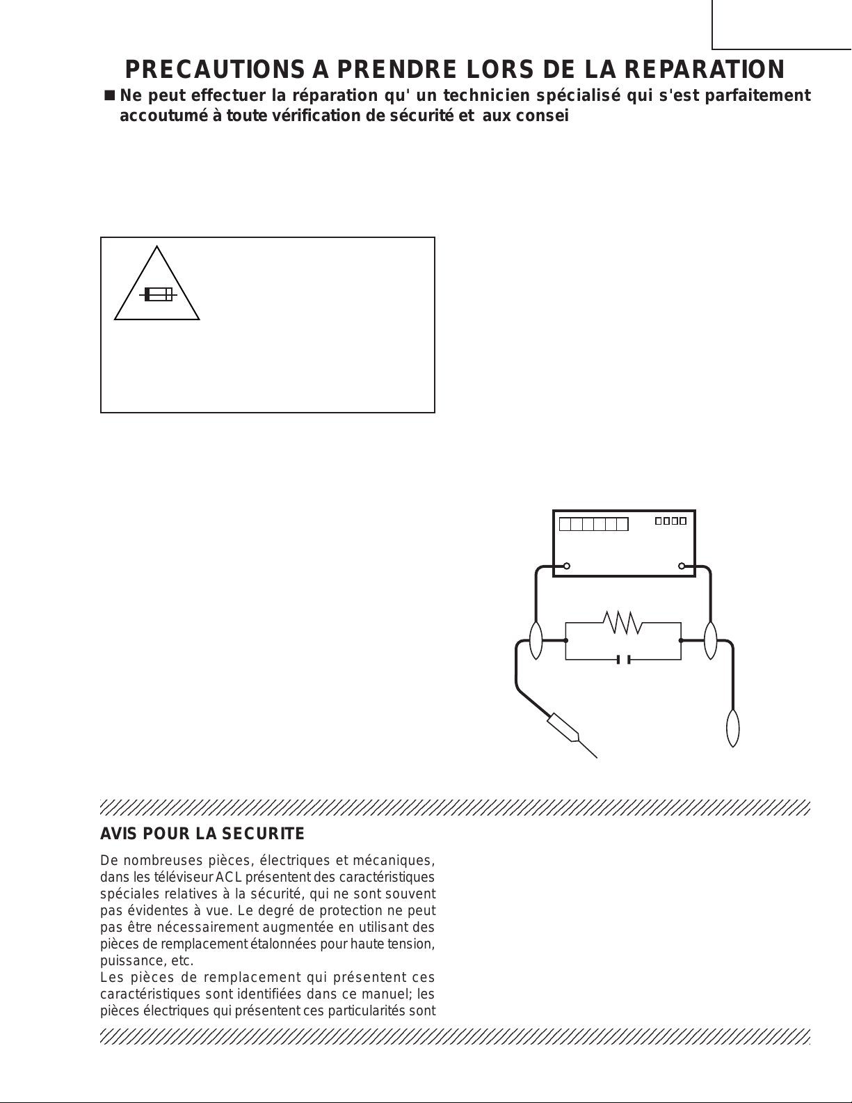
PRECAUTIONS A PRENDRE LORS DE LA REPARATION
Ë
Ne peut effectuer la réparation qu' un technicien spécialisé qui s'est parfaitement
accoutumé à toute vérification de sécurité et aux conseils suivants.
AVERTISSEMENT
de 0.15µF en série avec toutes les pièces métalliques
exposées du coffret et une terre connue comme une
1. N'entreprendre aucune modification de tout circuit.
C'est dangereux.
2. Débrancher le récepteur avant toute réparation.
PRECAUTION: POUR LA
PROTECTION CONTINUE
CONTRE LES RISQUES
A V
D'INCENDIE, REMPLACER LE
FUSIBLE
LC-26D4U:F701, F702 (3.15A, 250V)
LC-32D4U/LC-37D4U:
F701, F702 (5A, 250V)
F703 (1A, AC250V), F704 (117°C, 2A)
VERIFICA TIONS CONTRE L'INCEN-DIE ET
LE CHOC ELECTRIQUE
Avant de rendre le récepteur à l'utilisateur, effectuer
les vérifications suivantes.
conduite électrique ou une prise de terre branchée à
la terre.
• Utiliser un voltmètre CA d'une sensibilité d'au moins
5000Ω/V pour mesurer la chute de tension en travers
de la résistance.
• Toucher avec la sonde d'essai les pièces métalliques
exposées qui présentent une voie de retour au châssis
(antenne, coffret métallique, tête des vis, arbres de
commande et des boutons, écusson, etc.) et mesurer
la chute de tension CA en-travers de la résistance.
Toutes les vérifications doivent être refaites après avoir
inversé la fiche du cordon d'alimentation. (Si
nécessaire, une prise d'adpatation non polarisée peut
être utilisée dans le but de terminer ces vérifications.)
Tous les courants mesurés ne doivent pas dépasser
0.5 mA.
Dans le cas contraire, il y a une possibilité de choc
électrique qui doit être supprimée avant de rendre le
récepteur au client.
1. Inspecter tous les faisceaux de câbles pour s'assurer
que les fils ne soient pas pincés ou qu'un outil ne soit
pas placé entre le châssis et les autres pièces
métalliques du récepteur.
2. Inspecter tous les dispositifs de protection comme les
boutons de commande non-métalliques, les isolants,
DVM
ECHELLE CA
1.5k ohm
10W
le dos du coffret, les couvercles ou blindages de réglage
et de compartiment, les réseaux de résistancecapacité, les isolateurs mécaniques, etc.
3. S'assurer qu'il n'y ait pas de danger d'électrocution en
vérifiant la fuite de courant, de la facon suivante:
• Brancher le cordon d'alimentation directem-ent à une
0.15 µF
SONDE D'ESSAI
prise de courant de 120V. (Ne pas utiliser de
transformateur d'isolation pour cet essai).
• A l'aide de deux fils à pinces, brancher une résistance
de 1.5 kΩ 10 watts en parallèle avec un condensateur
234567890123456789012345678901212345678901234567890123456789012123456789012345678901234567890121
AUX PIECES
METALLIQUES
EXPOSEES
BRANCHER A UNE
TERRE CONNUE
AVIS POUR LA SECURITE
De nombreuses pièces, électriques et mécaniques,
dans les téléviseur ACL présentent des caractéristiques
spéciales relatives à la sécurité, qui ne sont souvent
pas évidentes à vue. Le degré de protection ne peut
pas être nécessairement augmentée en utilisant des
pièces de remplacement étalonnées pour haute tension,
puissance, etc.
Les pièces de remplacement qui présentent ces
caractéristiques sont identifiées dans ce manuel; les
pièces électriques qui présentent ces particularités sont
234567890123456789012345678901212345678901234567890123456789012123456789012345678901234567890121
234567890123456789012345678901212345678901234567890123456789012123456789012345678901234567890121
identifiées par la marque " å " et hachurées dans la
liste des pièces de remplacement
schématiques
.
et les
diagrammes
Pour assurer la protection, ces pièces doivent être
identiques à celles utilisées dans le circuit d'origine.
L'utilisation de pièces qui n'ont pas les mêmes
caractéristiques que les pièces recommandées par
l'usine, indiquées dans ce manuel, peut provoquer des
électrocutions, incendies, radiations X ou autres
accidents.
3
Page 4

LC-26D4U
LC-32D4U
LC-37D4U
Precautions for using lead-free solder
1 Employing lead-free solder
"PWBs" of this model employs lead-free solder . The LF symbol indicates lead-free solder, and is attached on the
PWBs and service manuals. The alphabetical character following LF shows the type of lead-free solder.
Example:
L Fa
Indicates lead-free solder of tin, silver and copper.
2 Using lead-free wire solder
When fixing the PWB soldered with the lead-free solder, apply lead-free wire solder. Repairing with conventional
lead wire solder may cause damage or accident due to cracks.
As the melting point of lead-free solder (Sn-Ag-Cu) is higher than the lead wire solder by 40°C, we recommend
you to use a dedicated soldering bit, if you are not familiar with how to obtain lead-free wire solder or soldering bit,
contact our service station or service branch in your area.
3 Soldering
As the melting point of lead-free solder (Sn-Ag-Cu) is about 220°C which is higher than the conventional lead
solder by 40°C, and as it has poor solder wettability, you may be apt to keep the soldering bit in contact with the
PWB for extended period of time. However, Since the land may be peeled off or the maximum heat-resistance
temperature of parts may be exceeded, remove the bit from the PWB as soon as you confirm the steady soldering
condition.
Lead-free solder contains more tin, and the end of the soldering bit may be easily corroded. Make sure to turn on
and off the power of the bit as required.
If a different type of solder stays on the tip of the soldering bit, it is alloyed with lead-free solder. Clean the bit after
every use of it.
When the tip of the soldering bit is blackened during use, file it with steel wool or fine sandpaper.
Be careful when replacing parts with polarity indication on the PWB silk.
Lead-free wire solder for servicing
Part No, ★ Description Code
ZHNDAi123250E J φ0.3mm 250g(1roll) BL
ZHNDAi126500E J φ0.6mm 500g(1roll) BK
ZHNDAi12801KE J φ1.0mm 1kg(1roll) BM
Indicates lead-free solder of tin, silver and copper.
4
Page 5
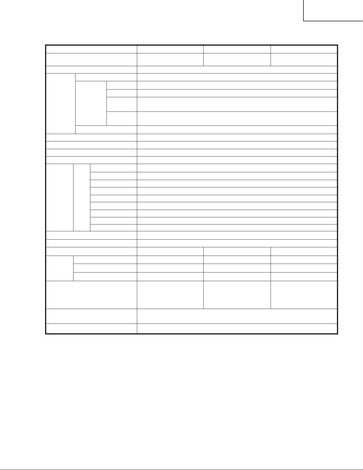
Specifications
LC-26D4U
LC-32D4U
LC-37D4U
Item Model: LC-37D4U
LCD panel 37" Advanced Super
View & BLACK TFT LCD
Model: LC-32D4U Model: LC-26D4U
32" Advanced Super
View & BLACK TFT LCD
26" Advanced Super
View & BLACK TFT LCD
Number of dots 3,147,264 dots (1366 X 768 X 3 dots)
TV
Function
TV-standard (CCIR)
Receiving
Channel
VHF/UHF
CATV 1-125ch
Digital Terrestrial
Broadcast (8VSB)
Digital cable
(64/256 QAM)
American TV Standard ATSC/NTSC System
VHF 2-13ch, UHF 14-69ch
2-69ch
1-135ch
Audio multiplex BTSC System
Brightness 450 cd/m
2
Backlight Life 60,000 hours (at Backlight Standard position)
Viewing angles H : 170° V : 170°
Audio out 10W X 2
Terminals
Rear
INPUT 1
INPUT 2
INPUT 3
AV in, COMPONENT in
AV in, COMPONENT in
S-VIDEO in, AV in
INPUT 4 Audio in, HDMI in with HDCP
ANALOG ANTENNA
DIGITAL ANTENNA
MONITOR OUTPUT
DIGITAL AUDIO OUTPUT
CableCARD slot
75 Ω Unbalance, F Type for VHF/UHF/CATV in m 1
75 Ω Unbalance, F Type X 2 (for Digital Air X 1/Digital Cable in X 1)
S-VIDEO out, AV out
Optical Digital audio output m 1 (PCM/Dolby Digital)
68 pin PCMCIA X 1
OSD language English/French/Spanish
Power Requirement
Power Consumption
Weight
TV only
Stand
TV with stand
Dimension (W X H X D)
AC 120 V, 60 Hz
188 W
46.3 lbs./21.0 kg
11.0 lbs./5.0 kg
57.3 lbs./26.0 kg
431/2 X 221/8 X 431/
inch (w/o stand),
1
43
/2 X 2515/32 X 1213/
inch (with stand)
146 W 124 W
37.5 lbs./17.0 kg 28.7 lbs./13.0 kg
6.6 lbs./3.0 kg 7.7 lbs./3.5 kg
44.1 lbs./20.0 kg 36.4 lbs./16.5 kg
64
64
37
/64 X
38
1913/32 X
inch (w/o stand),
3837/64 X
223/4 X
inch (with stand)
431/
113/
64
333/8 X
inch (w/o stand),
8
333/8 X
inch (with stand)
1629/64 X
199/16 X
431/
1035/
Accessories Operation manual ( X1), Remote control unit ( X 1), AC cord ( X1), “AAA” size
battery ( X2), Cable clamp ( X1), Cable tie ( X1)
Operating temperature +32°F to +104°F (0°C to + 40 ° C)
64
64
•As part of policy of continuous improvement, SHARP reserves the right to make design and specification changes for pr oduct improvement
without prior notice. The performance specification figures indicated are nominal values of production units. There may be some
deviations from these values in individual units.
5
Page 6

LC-26D4U
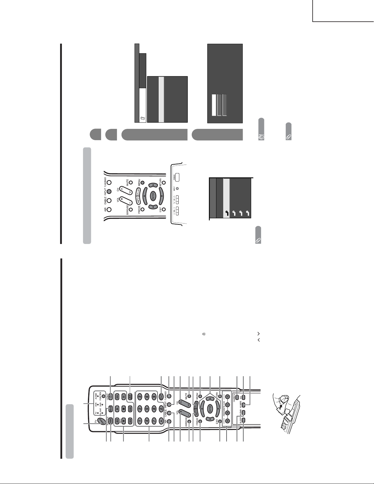
Part names
POWER indicator
OPC sensor
TV (Front)
POWER button
INPUT button
Volume buttons (VOL /)
Channel
buttons
(CH / )
Remote control sensor
*OPC: Optical Picture Control
*DL: DownLoad
OPC/DL indicator
NOTE
• For status indicator .
–
+
ù
Ù
Part names
TV (Rear)
* Press RESET if the TV cannot return to its original state after performing various operations.
•AV MODE resets to DYNAMIC (Fixed)
• TV channel returns to initial channel (Air:2ch, Cable:1 or 2ch)
• Audio setting initializes
• Surround resets to off
• Image position initializes
**Press SYSTEM RESET if the TV does not operate after starting up.
NOTE
•Pressing RESET will not work if the TV is in standby mode.
•Pressing RESET will not delete channel preset or secret number. For clearing the secret number when you
know it. For initializing to the factory preset values when you forget your secret number.
RESET*
INPUT 3
terminals
SYSTEM RESET**
ANALOG IN
terminal
AC INPUT terminal
RS-232C
terminal
INPUT 2
terminals
INPUT 1
terminals
INPUT 4 terminals
MONITOR OUTPUT terminals
CableCARD™ slot
DIGITAL AUDIO
OUTPUT terminal
DIGITAL AIR IN
terminal
DIGITAL CABLE
IN terminal
LC-32D4U
LC-37D4U
Operation Manual
6
Page 7
LC-26D4U
Part names
Remote control unit
2
317
18
19
20
21
22
23
24
25
26
27
28
29
30
116
4
5
6
7
8
9
11
12
13
14
15
10
1TV POWER: Switches the Liquid Crystal Television
power on or enters Standby mode.
2DISPLAY: Displays the channel information.
3 SOURCE POWER: Turns the power of the external
equipment on and off.
4 External equipment operational buttons: Operates
the external equipment.
50 – 9/• (DOT): Sets the channel.
6AIR: Receives air signal.
7 CABLE: Receives cable signal.
8VOL /–: Sets the volume.
9SURROUND: Selects Surround settings.
10 INFO: Displays the program information screen.
11 FREEZE: Sets the still image. Press again to return to
normal screen.
12 EXIT: Turns off the menu screen.
13 FAVORITE CH
A, B, C, D: Selects four preset favorite channels in four
different categories.
While watching, you can toggle the selected channels
by pressing A, B, C and D.
14 AUDIO: Selects the MTS/SAP or the audio mode during
multi-channel audio broadcasts.
15 SLEEP: Sets the sleep timer.
16 FUNCTION: Switches the remote control for TV, CBL/
SAT, VCR, DVD and AUDIO operation. Indicator lights
up for the current mode.
* To enter the code r egistration mode, you need to press
FUNCTION and DISPLAY at the same time.
17 LIGHT
: When pressed all buttons on the remote
control unit will light. The lighting will turn off if no
operations are performed within about 5 seconds. This
button is used for performing operations in low-light
situations.
18 VIEW MODE: Selects the screen size.
19 ENT: Enters a channel selection when choosing with
the 0-9 buttons.
20 FLASHBACK: Returns to the previous channel or
external input mode.
21 INPUT: Selects a Liquid Crystal T elevision input source.
(TV , INPUT 1, INPUT 2, INPUT 3, INPUT 4)
22 CH
/
: Selects the channel.
23 MUTE: Mutes the sound.
24 CH LIST: Displays the channel list screen.
25 MENU: Displays the menu screen.
26 ////ENTER: Selects a desired item on the
screen.
27 RETURN: Retur ns to the previous menu screen.
28 FAVORITE: Registers favorite channel.
29 CC: Displays captions when receiving closed-caption
signals.
30 AV MODE: Selects an audio or video setting.
(STANDARD, MOVIE, GAME, USER, DYNAMIC
(Fixed), DYNAMIC)
+
\ |
' "
Using external equipment
You can connect many types of external equipment to your TV, like a DVD player, VCR, Digital TV tuner, HDMI
equipment, game console and camcorder . To view external source images, select the input source from INPUT
on the remote control unit or on the TV.
CAUTION
•To protect all equipment, always turn off the TV before
connecting to a DVD player, VCR, Digital TV tuner, HDMI
equipment, game console, camcorder or other external
equipment.
NOTE
• For external equipment connection.
•Please refer to the relevant operation manual (DVD player,
etc.) carefully before making connections.
• Each time INPUT is pressed, the input source toggles.
• Refer to your external equipment operation manual for
the signal type.
Displaying an external equipment image
Explanation here is for the setting when connecting
DVD to INPUT1 terminal.
To watch a DVD image, select “INPUT1” from “INPUT
SOURCE” menu using INPUT on the remote control
unit or on the TV.
INPUT SOURCE
TV
INPUT1
INPUT2
INPUT3
INPUT4
1
Auto
COMPONENT
VIDEO
For INPUT1 signal
Select the desired signal type.
The setting is stored and can be selected on the
“INPUT SOURCE” menu.
Press MENU and the MENU screen displays.
2
3
Press / to select “Input Select”, and then
press ENTER.
4
Press / to select “Option”.
MENU
[
Option
...
Input Select
]
Option
Input Select
Digital Noise Reduction
Output Select
Audio Only
Quick Shoot
[Fixed]
[Auto]
[Low]
[On]
Caption Setup
Program Title Display
[No]
NOTE
• If the image does not come in clearly, you may need to
change the input signal type setting on the “Input Select”
menu.
Selecting the INPUT signal
\ |
' "
LC-32D4U
LC-37D4U
7
Page 8
LC-26D4U
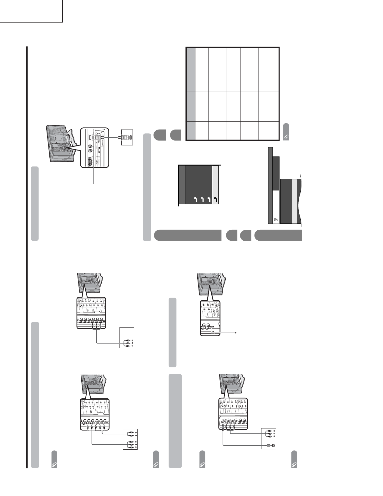
Using external equipment
DVD player/
Digital TV STB
Connecting a DVD player or a Digital TV STB (Air or Cable)
You can use the INPUT 1, INPUT 2 or INPUT 3 terminals when connecting to a DVD player, a Digital TV STB (Air
or Cable) and other audiovisual equipment.
NOTE
• If your cable-TV company has CableCARD security module available, you can also use the CableCARD security module
to receive HDTV programs.
NOTE
• For connecting a DVD player or a Digital TV STB to HDMI terminal.
AV cable
(commercially
available)
DVD player/
Digital TV STB
When using component cable. (INPUT 1 or 2)
When using composite cable. (INPUT 1, 2 or 3)
Component
video cable
(commercially
available)
Audio cable
(commercially
available)
VCR/Game console/
Camcorder
AV cable
(commercially available)
Connecting a VCR, game console or
camcorder
A VCR, game console, camcorder and some other
audiovisual equipment are conveniently connected
using the INPUT 1 to 3 terminals.
S-video cable
(commercially
available)
NOTE
• The S-video terminal has priority over the video terminals.
(INPUT 3 only)
To optical digital input of external audio devices
Optical fiber cable
Using Digital Audio Output
It is possible to output audio through the DIGITAL
AUDIO OUTPUT terminal.
PCM audio outputs from the terminal.
NOTE
• When attempting to record copy protected material on a VCR or other recording device, the copy protection will activate
and the protected material will not be recorded correctly. In addition, attempting to display copy protected material on a
monitor connected via a VCR, whether for the purpose of viewing or not, will cause an inferior quality picture to be
displayed. This is not a fault of the equipment. Please view copy protected material by connecting the product directly to
the monitor.
Using external equipment
Connecting HDMI equipment
Please use the INPUT 4 terminal when connecting HDMI equipment.
HDMI equipment
HDMI cable
(commercially available)
Displaying an image from HDMI equipment
To watch an HDMI equipment image, select
“INPUT4” from “INPUT SOURCE” menu
using INPUT on the remote control unit or
on the TV.
INPUT SOURCE
TV
INPUT1
INPUT2
INPUT3
INPUT4
1
Press MENU and the MENU screen displays.
2
3
Press / to select “HDMI Setup”, and then
press ENTER.
4
Press / to select “Option”.
MENU
[
Option
...
HDMI Setup
]
Option
Digital Noise Reduction
Audio Only
HDMI Setup
[Low]
5
Press / to select the desired item and
press ENTER.
Press / / / to select the desired setting
and press ENTER.
6
NOTE
•Refer to your external equipment operation manual for
the signal type.
Selectable items
RGB/YCbCr 4:4:4/
YCbCr 4:2:2
ITU601/ITU709
Standard/
Out of standard
Enable/Disable
Digital/Analog
HDMI Setup
items
Signal
Type
Color
Matrix
Dynamic
Range
Auto View
Audio
Select
Description
Select the video signal
type from the HDMI
terminal.
Select the internal color
space conversion method
when an RGB signal is
input.
Select the signal amplitude
range. Usually, select
“Standard”.
Set whether or not to use
VIEW MODE based on
signal recognition,
including an HDMI signal.
Select “Digital” for audio
signal via the HDMI
terminal. Select “Analog”
for audio signal via the R-
AUDIO -L terminal.
When using an HDMI-DVI
conversion cable, input the
audio signal to AUDIO
terminal of INPUT4.
\ |
\ |
' "
' "
' "
LC-32D4U
LC-37D4U
8
Page 9
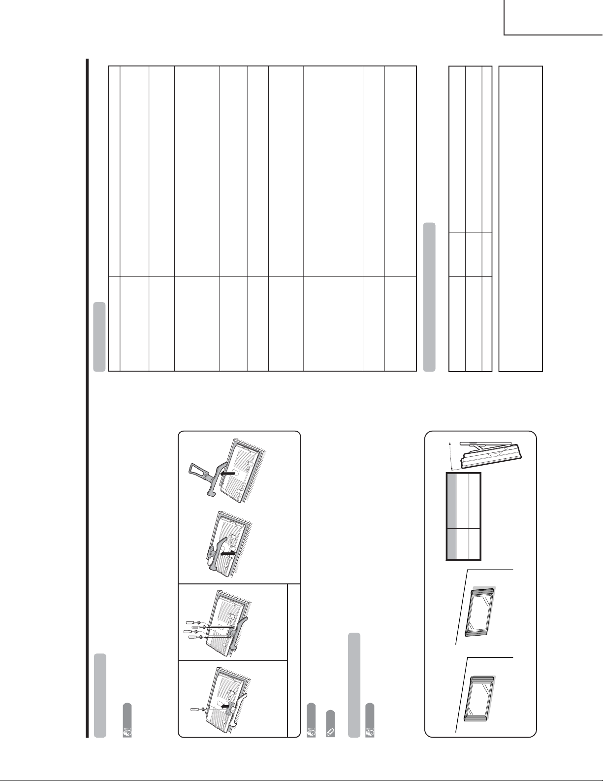
Appendix
Removing the stand
Before detaching (or attaching) stand, unplug the AC cord from the AC input terminal.
CAUTION
• Do not remove the stand from the TV unless using an optional wall mount bracket to mount it.
Before attaching/detaching stand
• Before performing work make sure to turn off the TV.
• Before performing work spread cushioning over the base area to lay the TV on. This will prevent it from being
damaged.
NOTE
•To attach the stand, perform the above steps in reverse order.
2
Unfasten the four screws
used to secure the stand in
place.
1
Unfasten the screw used to
secure the bracket in place.
Setting the TV on the wall
CAUTION
• Installing the Liquid Crystal Television requires special skill that should only be performed by qualified service
personnel. Customers should not attempt to do the work themselves. SHARP bears no responsibility for improper
mounting or mounting that results in accident or injury.
Using an optional bracket to mount the TV
•You can ask a qualified service professional about using an optional bracket to mount the TV to the wall.
• Carefully read the instructions that come with the bracket before beginning work.
Hanging on the wall
Wall mount bracket. (See the bracket instructions for details.)
About setting the TV angle
CAUTION
• Do not remove the stand from the TV unless using an optional bracket to mount it.
Vertical mounting Angular mounting
3
Detach the stand from the TV.
(Hold the stand so it will not drop from the edge of the
base area.)
Angle of TV
LC-37D4U
5˚
LC-32D4U 10˚
(LC-37/32D4U)
(LC-26D4U)
Start from step 2 for the 26 inch model to unfasten the
screws. Note that the shape of each stand differs.
Appendix
• No power
• Unit cannot be operated.
• Remote control unit does not
operate.
•Picture is cut off/with sidebar
screen.
• Strange color, light color , or color
misalignment
• Power is suddenly turned off.
• No picture
• No sound
• Upgrade is displayed continuously.
Problem Possible Solution
• Check if you pressed TV POWER on the remote control unit.
If the indicator on the TV is off, press POWER on the TV.
• Is the AC cord disconnected?
• External influences such as lightning, static electricity, may cause improper
operation. In this case, operate the unit after first turning on the power of the TV
or unplugging the AC cord and replugging it in after 1 or 2 minutes.
• Is the FUNCTION set correctly? Set it to the TV setting position.
•Are batteries inserted with polarity ( + , –) aligned?
•Are batteries worn out? (Replace with new batteries.)
•Are you using it under strong or fluorescent lighting?
• Is a fluorescent light illuminated near the remote control sensor?
• Is the image position correct?
•Are screen mode adjustments such as picture size made correctly?
• Adjust the picture tone.
• Is the room too bright? The picture may look dark in a room that is too bright.
• Is the sleep timer set?
• Check the power control settings.
• The unit’s internal temperature has increased.
Remove any objects blocking vent or clean the vent.
• Is connection to other components correct?
• Is correct input signal source selected after connection?
• Is the correct input selected?
• Is picture adjustment correct?
• Is “On” selected in “Audio Only”?
• If, after inserting the CableCARD security module, you are unable to receive
broadcast service, remove the CableCARD security module and reinsert.
• Is the volume too low?
• Is “Variable” selected in “Output Select”?
•Verify your antenna cable is connected property.
• Reinsert the CableCARD security module. If the trouble still exists after reinserting
the CableCARD security module and verifying the antenna cable, please contact
your Cable Provider Company.
Troubleshooting
Cautions regarding use in high and low temperature environments
• When the unit is used in a low temperature space (e.g. room, office), the picture may leave trails or appear slightly
delayed. This is not a malfunction, and the unit will recover when the temperature returns to normal.
• Do not leave the unit in a hot or cold location. Also, do not leave the unit in a location exposed to direct sunlight or near
a heater, as this may cause the cabinet to deform and the Liquid Crystal panel to malfunction.
Storage temperature: –4°F to +140°F (–20°C to +60°C)
Troubleshooting-Digital broadcasting
The error message about reception of broadcast
The example of an error message
displayed on a screen
Error code Possible Solution
• Failed to receive broadcast.
E202
• No broadcast now.
E203
• Check the antenna cable. Check that the antenna is correctly
setup.
• Check the broadcast time in the program guide.
LC-26D4U
LC-32D4U
LC-37D4U
9
Page 10

LC-26D4U
RS-232C port specifications
Return codeCommand 4-digits Parameter 4-digits
PC Control of the TV
• When a program is set, the TV can be controlled from the PC using the RS-232C terminal.
The input signal (PC/AV) can be selected, the volume can be adjusted and various other adjustments and
settings can be made, enabling automatic programmed playing.
•
Attach an RS-232C cable cross-type (commercially available) to the supplied Din/D-Sub RS-232C for the
connections.
NOTE
• This operation system should be used by a person who is accustomed to using computers.
Communication conditions
Set the RS-232C communications settings on the PC to match the TV’s communications conditions.
The TV’s communications settings are as follows:
Baud rate:
Parity bit:
Data length:
Stop bit:
Flow control:
9,600 bps
8 bits
None
1 bit
None
Appendix
Command format
Communication procedure
Send the control commands from the PC via the RS-232C connector.
The TV operates according to the received command and sends a response message to the PC.
Do not send multiple commands at the same time. Wait until the PC receives the OK response before sending
the next command.
Eight ASCII codes + CR
Command 4-digits:Command. The text of four characters.
Parameter 4-digits:Parameter 0 – 9, x, blank, ?
Parameter
Input the parameter values, aligning left, and fill with blank(s) for the remainder. (Be sure that 4 values are input for the
parameter.)
When the input parameter is not within an adjustable range, “ERR” returns. (Refer to “Response code format”.)
Any numerical value can replace the “x” on the table.
When “?” is input for some commands, the present setting value responds.
C1 C2 C3 C4 P1 P2 P3 P4
0055
100
–
30
0009
0
????
?
Command table
• Commands not indicated here are not guaranteed to operate.
CONTROL ITEM COMMAND
PARAMETER
CONTROL CONTENTS
POWER SETTING It shifts to standby.
It input-switches by the toggle. (It is the same as an input change key)
It input-switches to TV. (A channel remains as it is. (Last memory))
It input-switches to INPUT1~INPUT4.
An input change is also included.
Although it can choose now, it is toggle operation in inside.
Although it can choose now, it is toggle operation in inside.
(Toggle)
Input terminal number (1–4)
AUTO
VIDEO
COMPONENT
(Toggle)
STANDARD
MOVIE
USER
GAME
DYNAMIC (Fixed)
DYNAMIC
Volume (0–60)
AV mode. ( ±
±
10)
AV mode. ( 20)
(Toggle) [AV]
An input change is included if it is not TV display.
In Air, 2–69ch is effective.
In Cable, 1–125ch is effective.
If it is not TV display, it will input-switch to TV. (same function as CHù )
If it is not TV display, it will input-switch to TV. (same function as CHÙ )
Toggle operation of a closed caption.
Side Bar [AV]
S.Stretch [AV]
Zoom [AV]
Stretch [AV]
OFF
OFF TIMER – 30 MIN.
The channel number of TV
The channel number of TV +1
The channel number of TV –
1
(Toggle)
(1–125)
AUTO
POWR
ITGD
ITVD
IAVD
INP1
INPUT SELECTION A TOGGLE
INPUT SELECTION B
AV MODE SELECTION
VOLUME
POSITION
VIEWMODE
SLEEP TIMER
CHANNEL
Air/Cable SELECT
CC
DIRECT
(ANALOG)
(DIGITAL)
CH UP
CH DOWN
CHANNEL
H-POSITIONH-POSITION
V-POSITION
INPUT 1
AVMD
VOLM
HPOS
VPOS
OFTM
DCCH
CHUP
CHDW
CLCP
WIDE
0
x
x
*
0
1
2
0
*
*
*
0
*
x
x
x
1
0
1
2
3
4
1
2
3
4
5
6
*
_
_
_
_
_
_
_
_
_
_
*
*
*
_
_
_
_
_
_
_
_
_
_
_
_
_
_
*
_
_
_
_
_
_
_
_
_
_
*
*
_
_
_
_
_
_
_
_
_
_
_
_
_
_
_
_
DIGITAL Air (Two-Part numbers, 2-digit plus 2-digit)(0101-9999)
(0-999)
(0-999)
(0-9999)
(0-6383)
DIGITAL Cable (Two-Part numbers, 3-digit plus 3-digit)
DIGITAL Cable (Two-Part numbers, 3-digit plus 3-digit)
Front half of DIGITAL CABLE CHANNEL NO. (Designate major channel)
Rear half of DIGITAL CABLE CHANNEL NO. (Designate minor channel)
DIRECT
CHANNEL
DA2P* * * *
DC2U * * * _
DC2 L * * *_
DIGITAL Cable (One-Part numbers, 5-digit, less than 10,000)
DC1 0 * * * *
DIGITAL Cable (One-Part numbers, 5-digit, more than 10,000)
DC1 1 * * * *
_
_
AIR
CABLE AIR(Toggle)ACSL 0 _ __
AIR1___
CABLE2___
_
(Toggle)
AUDIO SELECTION
ACHAx _ _ _
_
_
OFF TIMER – 60 MIN.
OFF TIMER – 90 MIN.
2
3
_
_
_
_
_
_
OFF TIMER – 120 MIN. 4___
(Toggle)
On
Off
MUTE
MUT E 0
1
2
_
_
_
_
_
_
_
_
_
(Toggle)
On
Off
SURROUND
ACSU0
1
2
_
_
_
_
_
_
_
_
_
_
_
_
_
_
_
_
_
_
_
_
_
_
_
_
AUTO
VIDEO
COMPONENT
AUTOINP2
INPUT 2
0
1
2
_
_
_
_
_
_
_
_
_
_
_
_
_
_
_
_
TV
INPUT1-4
Appendix
NOTE
• If an underbar (_) appears in the parameter column, enter a space.
• If an asterisk (*) appears, enter a value in the range indicated in brackets under CONTROL CONTENTS.
• As long as that from which the parameter (
X
) in the table is a numerical value, it may write anything.
Return code (0DH)
Response code format
Normal response
Problem response (communication error or incorrect command)
Return code (0DH)
OK
ERR
LC-32D4U
LC-37D4U
10
Page 11
LC-26D4U
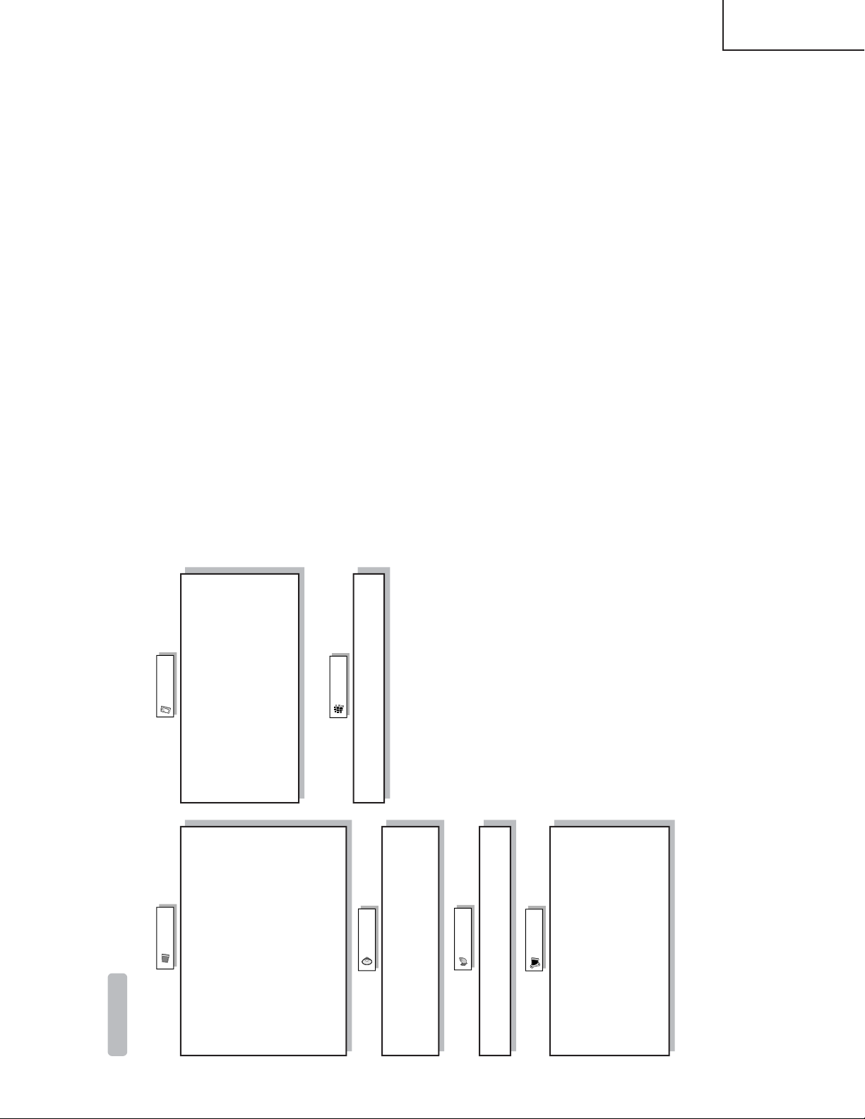
Menu items
List of menu items to help you with operations
OPC
Backlight
Contrast
Brightness
Color
Tint
Sharpness
Advanced
Color Temp.
Black
3D-Y/C
Monochrome
Film Mode
Picture
No Signal Off
No Operation Off
EZ Setup
CH Setup
Antenna Setup-DIGITAL
Input Label
Parental CTRL
Position
Picture Flip
Standby Mode
Language
Treble
Bass
Balance
Surround
Audio Only
Digital Noise Reduction
HDMI Setup
Input Select
Output Select
Quick Shoot
Caption Setup
Program Title Display
Color System
Audio
Power Control
Setup
Option
CableCARD Menu
Audio Setup
Digital Setup
LC-32D4U
LC-37D4U
11
Page 12

LC-26D4U
LC-32D4U
LC-37D4U
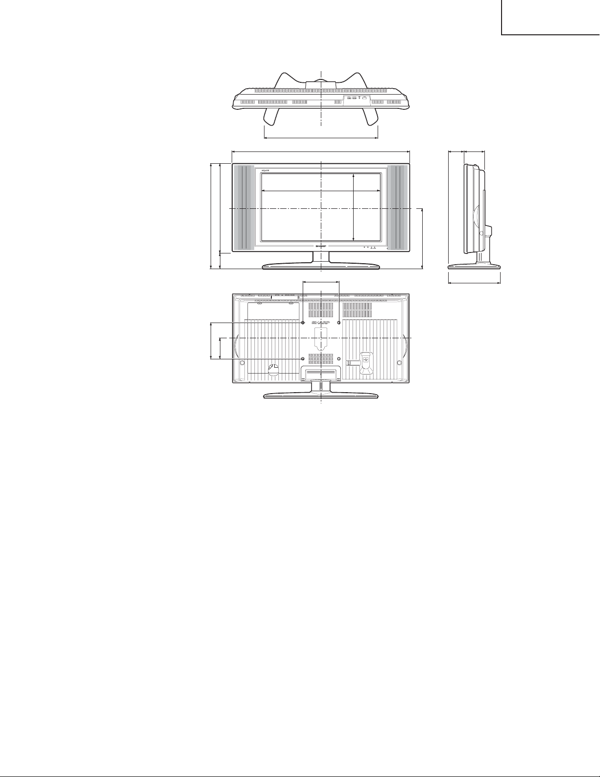
Dimensions
LC-26D4U
/16 (497)
9
19
/16 (100)
15
3
/64 (418)
29
16
/64 (79)
7
3
/32 (50)
31
1
2223/64 (567.9)
223/64 (560)
333/8 (848)
315/16 (100)
/8 (320.6)
5
12
/8 (289)
3
11
21/8 (54)
Unit: inch/(mm)
431/64 (114)
1035/64 (268)
31
/32 (482)
18
LC-32D4U
/4 (578)
3
22
/8 (200)
7
7
/32 (493)
13
19
/32 (85)
11
3
/64 (115)
33
4
2737/64 (700.4)
247/8 (632)
3837/64 (980)
77/8 (200)
/64 (395.1)
35
15
/8 (333.5)
1
13
335/64 (90)
Unit: inch/(mm)
431/64 (114)
113/8 (289)
12
Page 13
LC-26D4U
LC-32D4U
LC-37D4U
LC-37D4U
/32 (647)
15
25
/8 (200)
7
7
/8 (562)
1
22
/32 (85)
11
3
/32 (104)
3
4
323/8 (822.6)
2613/32 (671)
431/2 (1105)
77/8 (200)
/64 (463.9)
17
18
/64 (367.8)
31
14
41/8 (105)
Unit: inch/(mm)
431/64 (114)
123/64 (306)
13
Page 14
LC-26D4U
LC-32D4U
LC-37D4U
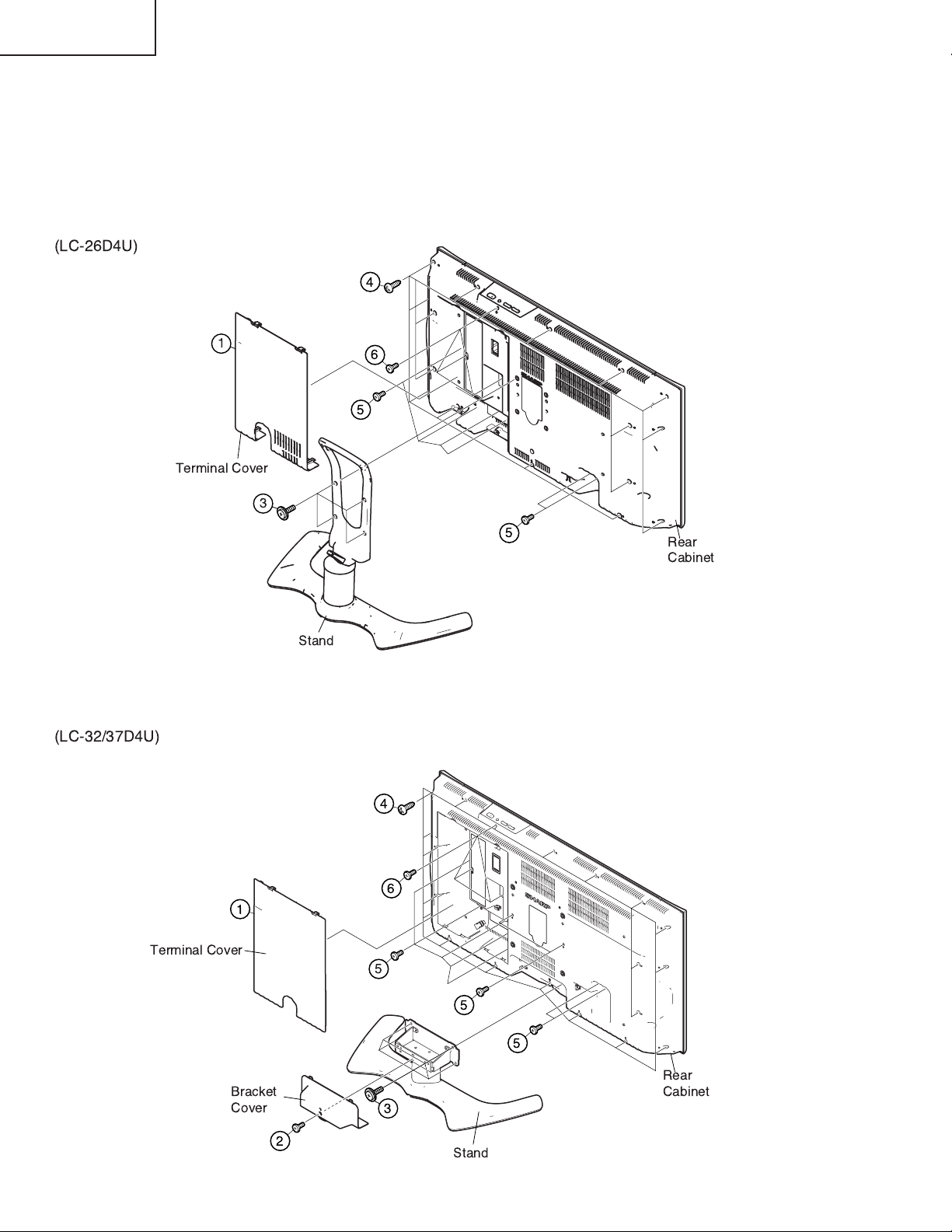
REMOVING OF MAJOR PARTS
1. Remove the Terminal Cover 1.
2. Remove the 1 lock screw 2 and detach the Bracket Cover (LC-32/37D4U only).
3. Remove the 4 lock screws 3 and detach the Stand.
4. Remove the Rear Cabinet.
LC-26D4U: Remove the 16 lock screws 4, 6 lock screws 5, 6 lock screws 6 and detach the Rear Cabinet.
LC-32/37D4U: Remove the 19 lock screws 4, 9 lock screws 5, 7 lock screws 6 and detach the Rear Cabinet.
!
14
Page 15
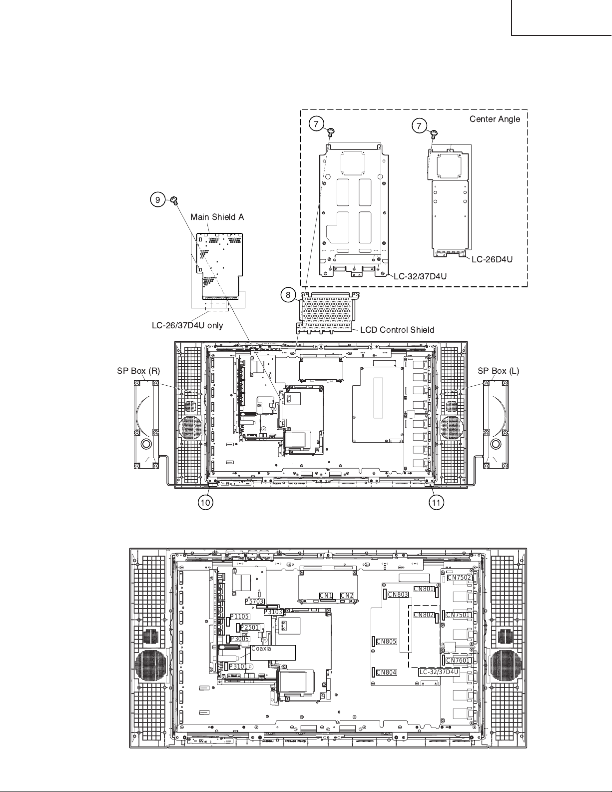
5. Remove the 4 (LC-26D4U) / 7 (LC-32/37D4U) lock screws 7 and detach the Center Angle.
6. Detach the LCD Control Shield 8.
7. Remove the 5 (LC-26/37D4U) / 3 (LC-32D4U)lock screws 9 and detach the Main Shield A.
8. Disconnect the connectors 0 and q, and detach the SP Box (R) and SP Box (L).
LC-26D4U
LC-32D4U
LC-37D4U
#!"
!"
# !" $
9. Remove the connectors,(P5703,P3103,P1105,P2501,P3005,P3101,CN1,CN2,CN801,CN802,CN803,
CN804,CN805,CN7502,CN7501,and CN7601) Remove the 2 Coaxial Cables,(RED and BLACK).
CN7502
CN801
P5703
P1105
P2501
P3005
P3101
P3103
Coaxial Cables
RED & BLACK
CN1
CN2
CN803
CN805
CN804
CN802
LC-32/37D4U
CN7501
CN7601
15
Page 16

LC-26D4U
LC-32D4U
LC-37D4U
10. Remove the 4 lock screws w and FFC. Detach the Main Shield B and Digital PWB.
11. Remove the 4 lock screws e and detach the Digital PWB.
12. Remove the 2 lock screws r and detach the Jack Cover C.
13. Remove the 2 lock screws t and detach the Main PWB.
14. Remove the 3 lock screws y and the 1 lock screw u, and detach the AV PWB. Remove 1 lock screw i and
detach the Jack Cover B. Remove the 4 lock screws o and detach the Jack Cover A.
15. Remove the 6 lock screws p and detach the Power PWB.
16. Remove the 4 lock screws a and detach the LCD Control PWB.
17. Remove the 2 lock screws s and detach the R/C, LED PWB.
18. Remove the KEY PWB.
18-1. Remove the 2 lock screws d from the Top Control Cover.
18-2. Remove the 3 lock screws f from the KEY PWB.
(
!"# $
+, $
)*
'
!"# $
%
&
!"# $
16
-
Page 17
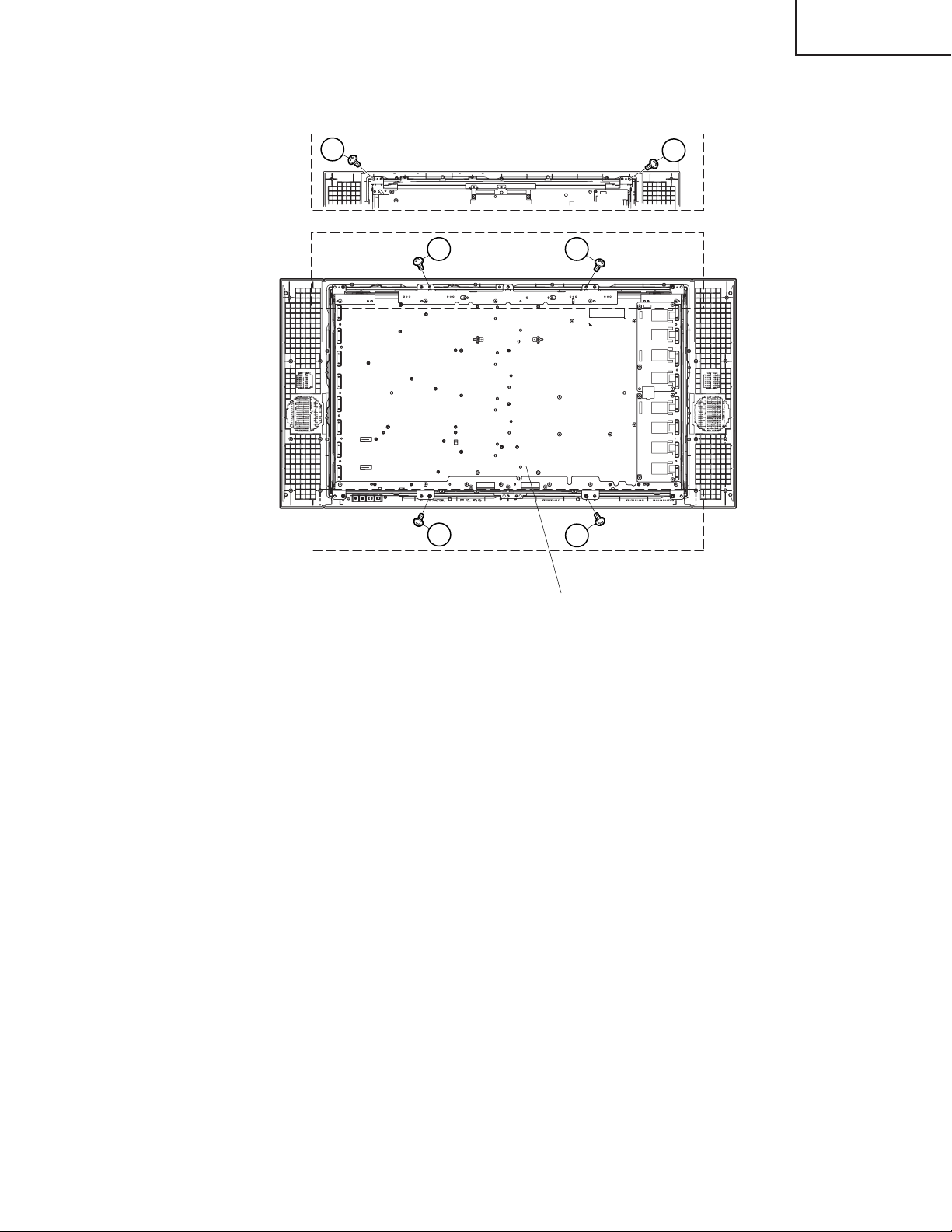
19. Remove the lock screws g (LC-26D4U:2, LC-32D4U:4) and take out of the LCD Panel Module.
LC-26D4U
LC-32D4U
LC-37D4U
25
LC-32/37D4U
LC-26D4U
25 25
LC-32/37D4U
25
25
25
LCD Panel Module
17
Page 18

LC-26D4U
LC-32D4U
LC-37D4U
ADJUSTMENT PROCEDURE
The adjustment values are set to the optimum conditions at the factory before shipping. If a value should
become improper or an adjustment is required due to part replacement, make an adjustment according to the
following procedure.
1. After replacement of any PWB unit and/or IC for repair, please note the following.
When replacing the following units, make sure to prepare the new units loaded with updated software.
MAIN Unit: DUNTKD376FE04 (LC-26D4U) / DUNTKD376FE05 (LC-32D4U) / DUNTKD376FE06(LC-37D4U)
2.Upgrading of each microprocessor software
Caution: Never "POWER OFF" the unit when software upgrade is ongoing.
Otherwise the system may be damaged beyond recovery.
2-1 Software version upgrade
The model employs the following software.
» Main software
» Monitor microprocessor software
The main software and the monitor microprocessor software can be upgraded by using a general-purpose SD
memory card.
The followings are the procedures for upgrading, explained separately for each of the main software, the
monitor microprocessor software.
2-2 Main software version upgrade
Get ready before you start
» SD memory card of 32MB or higher capacity
» PC running on Windows 98/98SE/ME/2000/XP operating system
» SD memory card reader/writer with USB connectivity.
» SD memory card formatting software
(Downloadable at http://panasonic.jp/support/audio/sd/download/sd_formatter_e.html)
18
Page 19

LC-26D4U
LC-32D4U
LC-37D4U
Preparations
To upgrade the main software, it is necessary to get ready the SD card for version upgrade before you start.
Follow the steps below and create the SD card for version upgrade.
1 Insert the SD card into the SD card reader/writer. Start the SD card formatting software. Click [Format].
(When you have the drive options, select the drive where the SD card is inserted before you proceed.)
2 When the formatting is over, the following window appears. Click [OK].
3 Click [Exit] to finish the formatting.
Note: When you are done, take out the SD card once to make sure it is finished, and then insert it again.
4 Copy the binary image file KX5Uxxxx.SDC (named temporarily) for version upgrade to the root directory
(folder) of the SD card drive.
Note: In the SD card drive, do not store other folders or unrelated files, or more than one binary image files for
version upgrade.
Now the SD card for version upgrade is ready.
19
Page 20

LC-26D4U
LC-32D4U
LC-37D4U
How to upgrade the software
1 Shut off the AC power (i.e. unplug the AC cord).
2 Insert the SD card for version upgrade (prepared as above) into the service socket located below left of the
right side cooling fan in the rear of the unit, in a way that the cut corner of the SD card comes at the righthand side.
Note: If the SD card is inserted in a wrong way, the card will go deep inside the unit beyond retrieval. Take due
care to insert the SD card correctly.
3 While depressing the SYSTEM RESET button located in the rear left side of the unit, turn on the AC power
(i.e. plug in the AC cord).
Note: After the unit is started, you may release the SYSTEM RESET button.
4 After the unit startup, the system upgrade screen as shown below appears within 20-40 seconds.
5 Even a single failure in the process will trigger the upgrade failure screen as shown below. The word "NG"
changes to red for the item failed.
Note: In the event of a failure, repeat the upgrading process. If the process repeatedly fails, it is likely that the
hardware is troubled.
6 Upon completion of the whole process, the upgrade success screen as shown below appears. You can
check the new software version on this screen. The version information appears after the upgrade is
complete.
20
Page 21

LC-26D4U
LC-32D4U
LC-37D4U
7 Shut off the AC power to the unit (unplug the AC cord), and remove the SD card for version upgrade.
8 Now the software version upgrade is complete.
Note: When you are done with the software version upgrade, start the set, go to the top page of the adjustment
process screen and check the main software version information.
2-3 Monitor microprocessor software version upgrade
Get ready before you begin
Get ready the same items as listed in the "Main software version upgrade".
Preparation
Create the SD card for monitor microprocessor software version upgrade in the same manner as explained in
the "Main software version upgrade". Copy the binary image file for monitor microprocessor software version
upgrade to the SD card drive.
How to upgrade the software
During the monitor microprocessor software version upgrade, the progress of upgrading is not shown on the
display screen. The upgrading process is seen in the blinking of the power LED.
1 Shut off the AC power to the unit (i.e. unplug the AC cord).
2 Insert the SD card for version upgrade (prepared as above) into the service socket located below left of the
right side cooling fan in the rear of the unit, in a way that the cut corner of the SD card comes at the righthand side.
Note: If the SD card is inserted in a wrong way, the card will go deep inside the unit beyond retrieval. Take due
care to insert the SD card correctly.
3 While depressing the SYSTEM RESET button located in the rear left side of the unit, turn on the AC power
(i.e. plug in the AC cord).
Note: After the unit is started, you may release the SYSTEM RESET button.
Caution!!
The moment this operation is done, the upgrading of the monitor microprocessor software starts.
While the upgrade is ongoing, never power off the unit. Otherwise the upgrade will fail and the
system may have a serious damage beyond recovery (inability to start).
4 After the unit startup, the power LED starts blinking within 10-20 seconds.
5 Wait until the power LED stops blinking, the unit restarts automatically, and the normal startup screen
appears (it will take 2-3 minutes).
6 Shut off the AC power to the unit (unplug the AC cord), and remove the SD card for version upgrade.
7 Now the software version upgrade is complete.
Note: When you are done with the software version upgrade, start the set, go to the top page of the adjustment
process screen and check the monitor microprocessor software version information.
21
Page 22

LC-26D4U
LC-32D4U
LC-37D4U
3.Entering and exiting the adjustment process mode
(1) Before entering the adjustment process mode, press the "RESET" button or execute the AV position RE-
SET in the video adjustment menu.
(2) While holding down the "VOL (–)" and "INPUT" keys at a time, plug in the AC cord of the main unit to turn
on the power.
The letter “ <K> ” appears on the screen.
(3) Next, hold down the "VOL (–)" and "CH (Ù)" keys at a time.
(The VOL " (–)" and "CH (Ù)" keys should be pressed and held until the display appears.)
Multiple lines of blue characters appearing on the display indicate that the unit is now in the adjustment
process mode.
When you fail to enter the adjustment process mode (the display is the same as normal startup), retry the
procedure.
(4) To exit the adjustment process mode after the adjustment is done, unplug the AC cord from the outlet to
make a forced shutdown. (When the power was turned off with the remote controller, once unplug the AC
cord and plug it again. In this case, wait 10 seconds or so before plugging.)
Caution: Use due care in handling the information described here lest your users should
know how to enter the adjustment process mode. If the settings are tampered in this mode,
unrecoverable system damage may result.
4.Remote controller key operation and description of display in adjustment process
mode
(1) Key operation
Remote controller key Main unit key Function
CH (Ù/ù) CH (Ù/ù) Moving an item (line) by one (UP/DOWN)
VOL (+/–) VOL (+/–) Changing a selected item setting (+1/_1)
Cursor (UP/DOWN) Turing a page (PREVIOUS/NEXT)
Cursor (LEFT/RIGHT) Changing a selected line setting (+10/_10)
INPUT Input switching (toggle switching)
(TUNER→INPUT1→INPUT2→INPUT3→INPUT4→INPUT5)
ENTER Executing a function
* Input mode is switched automatically when relevant adjustment is started so far as the necessary input
signal is available.
(2) Description of display
(3) Currently selected input
(2) Current page title
(1) Current page /
Total pages
(4) Current color TV system
(5) Destination
MAIN Version
Monitor Version
VMOUSE Version
EQ DATA CHECKSUM
TEMPERATURE
STANDBY CAUSE
1/14
[INFO]
TUNER
0.90 (U 2004/05/15 1)
3.06
A1AE
2C3
0
N358
22
USA
Adjustment process menu header
(7) Parameters
Page 23

5. List of adjustment process mode menu
The character string in brackets [ ] will appear as a page title in the adjustment process menu header.
Page Line Item Description Remarks (adjustment detail, etc.)
1 [INFO]
1 MAIN Version
2 Monitor Version Monitor version Obtained from the monitor. (Displays panel size and type as well.)
3 VMOUSE Version
4 EQ DATA CHECKSUM Audio data checksum Audio data checksum display
5 TEMPERATURE 2BE
6 STANDBY CAUSE Standby cause Last status which caused standby
2 [INIT]
1 INDUSTRY INIT
2 HOTELMODE Hotel mode settings
3 Center Acutime
4 RESET Reset
5 Backlight Acutime
6 RESET Reset
7 VIC XPOS
8 VIC YPOS
9 VIC COLOR
10 VIC SIGNAL_TYPE
11 VIC READ
3 [N358MAIN]
1 N358 ALL ADJ N358MAIN+SUB+TUNER Auto N358 Main, Sub and Tuner DAC adjustments
2 N358 MAIN ADJ Auto ALL Auto N358 Main video adjustment
3TUNER DAC ADJ IC400
4N358 MAIN CONTRAST IC400 Contrast
5 N358 MAIN Cb GAIN IC400 Cb gain
6 N358 MAIN Cr GAIN IC400 Cr gain
7 TUNER A DAC TUNER-A DAC Tuner DAC
4 [TUNER TEST]
1
TUNER VCHIP TEST(69ch)
2
TUNER VCHIP TEST (7ch)
3
TUNER VCHIP TEST(10ch)
4
TUNER VCHIP TEST(15ch)
5 [COMP15KMAIN]
1 COMP15K ALL ADJ Auto ALL Auto COMP15K Main + Sub adjustments
2 COMP15K MAIN ADJ Auto ALL
3
COMP15K MAIN CONTRAST
4 COMP15K MAIN Cb GAIN IC400 Cb gain
5 COMP15K MAIN Cr GAIN IC400 Cr gain
6 COMP15K Y OFFSET
7 COMP15K Cb OFFSET
8 COMP15K Cr OFFSET
6 [COMP15KSUB]
7 [HDTV]
1 HDTV ADJ Auto HDTV video adjustment
2 CONTRAST IC3700 Contrast
3 Cb GAIN IC3700 Cb gain
4 Cr GAIN IC3700 Cr gain
5 HDTV Y OFFSET
6 HDTV Cb OFFSET
7 HDTV Cr OFFSET
8 [DVI ANALOG]
1 DVI ANALOG Auto DVI analog video adjustment
2R CUTOFF IC3700
3G CUTOFF IC3700
4B CUTOFF IC3700
5R DRIVE IC3700
6G DRIVE IC3700
7B DRIVE IC3700
Main microprocessor version
Initialization to factory settings
Accumulated AVC operation time
Accumulated monitor operation time
Enter
Enter
Enter
Enter
IC400 Contrast
Version display
Initialization to factory settings
Reset by initialization
Not reset by initialization
LC-26D4U
LC-32D4U
LC-37D4U
23
Page 24
LC-26D4U
LC-32D4U
LC-37D4U
9 [DVI DIGITAL]
1 DVI DIGITAL Auto DVI digital video adjustment
2 CONTRAST IC3700 Contrast
3R CUTOFF
4G CUTOFF
5B CUTOFF
6R DRIVE
7G DRIVE
8B DRIVE
10 [M GAMMA]
1 MONITOR R GAMMA LO Monitor W/B adjustment
2 MONITOR G GAMMA LO
3 MONITOR B GAMMA LO
4 MONITOR R GAMMA HI
5 MONITOR G GAMMA HI
6 MONITOR B GAMMA HI
7 GAMMA WRITE Writing in monitor gamma table
8 GAMMA RESET Reset of monitor gamma table
11 [M GAMMA6 R]
1 MONITOR R GAMMA 1
2 MONITOR R GAMMA 2
3 MONITOR R GAMMA 3
4 MONITOR R GAMMA 4
5 MONITOR R GAMMA 5
6 MONITOR R GAMMA 6
7 GAMMA WRITE
8 GAMMA RESET
12 [M GAMMA6 G]
1 MONITOR G GAMMA 1
2 MONITOR G GAMMA 2
3 MONITOR G GAMMA 3
4 MONITOR G GAMMA 4
5 MONITOR G GAMMA 5
6 MONITOR G GAMMA 6
7 GAMMA WRITE
8 GAMMA RESET
13 [M GAMMA6 B]
1 MONITOR B GAMMA 1
2 MONITOR B GAMMA 2
3 MONITOR B GAMMA 3
4 MONITOR B GAMMA 4
5 MONITOR B GAMMA 5
6 MONITOR B GAMMA 6
7 GAMMA WRITE
8 GAMMA RESET
14 [ETC]
1 EEP SAVE
2 EEP RECOVER
3 STANDBY CAUSE RESET
Storage of adjustment value
Retrieval of adjustment value
Saving adjustment value in storage area
Retrieving adjustment value from storage area
6. LCD panel adjustment
COM BIAS adjustment
Adjustment item Adjustment conditions Adjustment procedure
1 COM BIAS Visual check
1.Follow the "Display adjustment procedure" in section 11 to enter the process
adjustment mode.
2.Move curser to "COMBIAS" with the "Cursor UP/DOWN" key on the remote
control and select a value with the "RIGHT/LEFT" key.
3.When the value is changed with the "Cursor UP/DOWN" key, a test pattern
appears. Make an adjustment so that the flicker in the center of the screen
is minimized.
4.After the adjustment, press the "ENTER" key on the remote control to exit.
24
Page 25
7. Special features
* STANDBY CAUSE (Page 1/14)
Display of a cause (code) of the last standby
The cause of the last standby is recorded in EEPROM whenever possible.
Checking this code will be useful in finding a problem when you repair the troubled set.
* EEP SAVE (Page 14/14)
Storage of EEP adjustment value
* EEP RECOVER (Page 14/14)
Retrieval of EEP adjustment value from storage area
8. Video signal adjustment procedure * Adjustment process mode menu is listed in section 5.
(1) Signal check
Signal generator level adjustment check (Adjustment to the specified level)
» Composite signal : 0.714Vp-p ± 0.02Vp-p (Pedestal to white level)
» 15K component signal : Y level : 0.714Vp-p ± 0.02Vp-p (Pedestal to white level)
PB, PR level
» 33K component signal : Y level : 0.714Vp-p ± 0.02Vp-p (Pedestal to white level)
PB, PR leve
» DVI-I (analog RGB) signal : RGB level : 0.714Vp-p ± 0.02Vp-p (Pedestal to white level)
: 0.7Vp-p ±0.02Vp-p
l: 0.7Vp-p ±0.02Vp-p
LC-26D4U
LC-32D4U
LC-37D4U
(2) Entering the adjustment process mode
Enter the adjustment process mode according to the steps described in section 3.
(3) N358 composite signal adjustment (Main, Sub and Tuner)
Adjustment item Adjustment conditions Adjustment procedure
1 Adjustment N358 signal
2 Auto adjustment Page 3/14
performance
Feed the PAL split field color bar signal (75% color saturation) to VIDEO 1
input.
Feed the RF signal (by use of US-10ch) to TUNER-A.
[Video input signal] [US-10CH]
↑100% white ↑100% white
Bring the cursor on [ËN358 ALL ADJ] and press [ENTER].
[ËN358 ALL ADJ FINISH] appears when finished.
25
Page 26

LC-26D4U
LC-32D4U
LC-37D4U
(4) Component 15K signal adjustment (Main)
Adjustment item Adjustment conditions Adjustment procedure
1 Adjustment 480i signal
Feed the 100% color bar signal to INPUT 1 component input.
↑100% white
2 Auto adjustment Page 5/14
performance
(5) Component 33K signal adjustment
Adjustment item Adjustment conditions Adjustment procedure
1 Adjustment 1080i signal
2 Auto adjustment Page 7/14
performance
(6) DVI-I (analog) signal adjustment
Bring the cursor on [ËCOMP 15K ALL ADJ] and press [ENTER].
[ËCOMP 15K ALL ADJ FINISH] appears when finished.
Feed the 100% color bar signal to INPUT 1 component input.
↑100% white
Bring the cursor on [ËHDTV ADJ] and press [ENTER].
[ËHDTV ADJ FINISH] appears when finished.
Adjustment item Adjustment conditions Adjustment procedure
1 Adjustment DVI-I (analog)
XGA (1024 x 768)
60Hz
H,V SYNC
2 Auto adjustment Page 8/14
performance
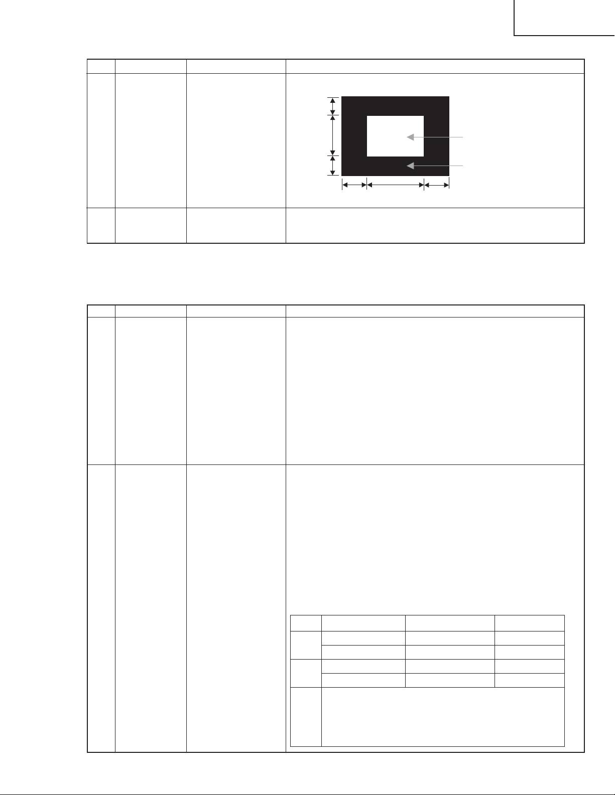
Feed the 100% white 1/2 window pattern signal to DVI-I (analog) input.
1/4
1/2
1/4
1/4
Bring the cursor on [ËDVI ANALOG] and press [ENTER].
[ËDVI ANALOG FINISH] appears when finished.
1/2
26
100% White
0% Black
1/4
Page 27
(7) DVI-I (digital) signal adjustment
Adjustment item Adjustment conditions Adjustment procedure
1 Adjustment DVI-I (digital)
XGA (1024 x 768)
60Hz
H,V SYNC
LC-26D4U
LC-32D4U
LC-37D4U
Feed the 100% white 1/2 window pattern signal to DVI-I (digital) input.
1/4
1/2
100% White
2 Auto adjustment Page 9/14
performance
8. Adjustment of white ballance
(1) White ballance adjustment
Adjustment item Adjustment conditions Adjustment procedure
1 Adjustment
1/4
1/4
Bring the cursor on [ËDVI DIGITAL] and press [ENTER].
[ËDVI DIGITAL FINISH] appears when finished.
1.Apply the following settings to the set.
AV MODE: [STANDARD]
Aging Time: 60 Min.
2.Connect a white balance adjustment jig and the set.
Optical measuring machine: [Minolta CA-210]
PC
RS-232C communication cable
3.Use an RS-232C command to display the screen for two-point adjustment.
◆Two-point adjustment mode (MSET0000)
◆Adjustment value initialization (MSET0004)
◆Low-side adjustment point setting (SDML0057)
◆High-side adjustment point setting (SDMH0204)
1/2
1/4
0% Black
2 Auto adjustment
performance
[Adjustment]
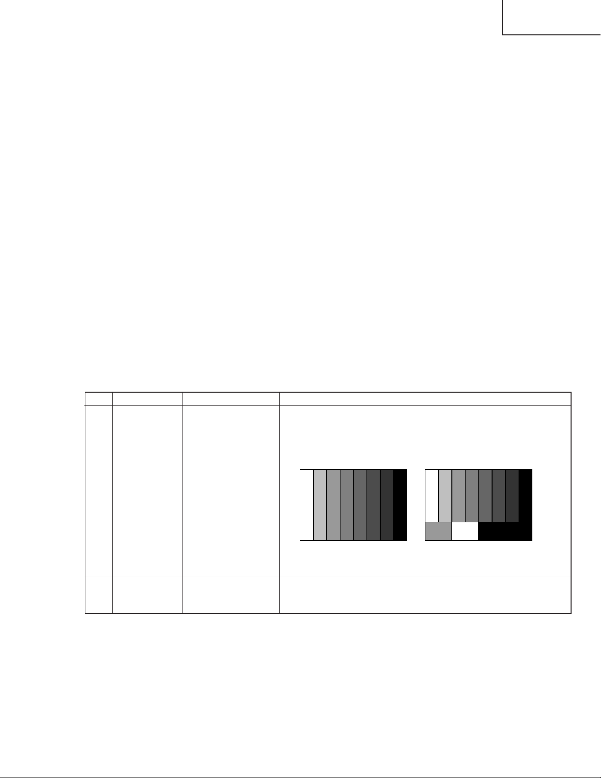
1.Set the low-side adjustment point to 57 (SDML0057). For RB, adjust the
chromaticity of the low-side adjustment pattern to standard values using
commands.
(G fixed)
2.Set the high-side adjustment point to 204 (SDMH0204). For RGB, adjust
the chromaticity of the high-side adjustment pattern to standard values
using commands. (Negative adjustment)
3.Write the adjustment values with MSET0003 command and turn off AC
power.
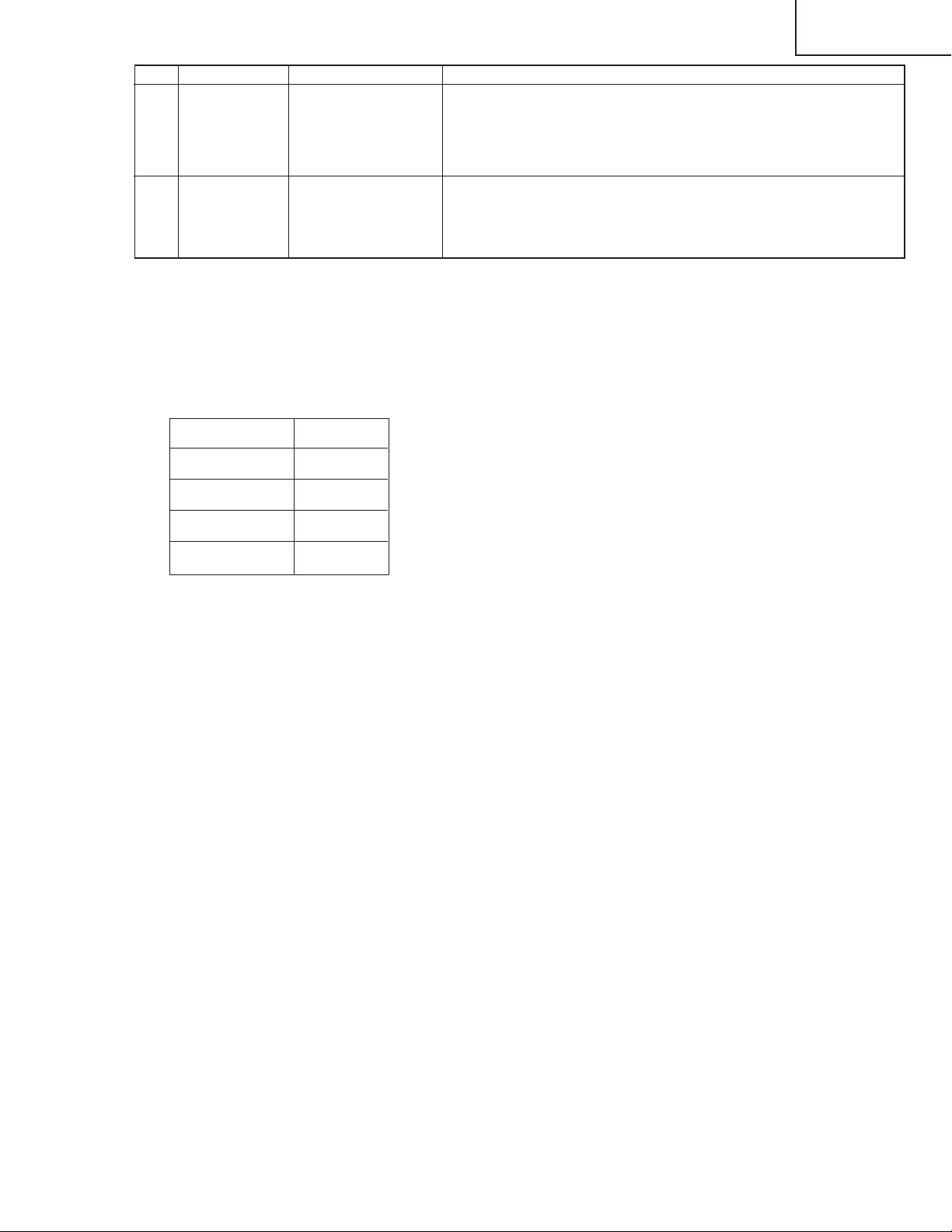
[Adjustment values]
Optical measuring machine: [Minolta CA-210] (Focus on the center of the
screen.)
Standard value Adjustment value Tolerance
High x = 0.295 ± 0.0004 ± 0.0015
y = 0.305 ± 0.0004 ± 0.0015
Low x = 0.276 ± 0.001 ± 0.0035
y = 0.283 ± 0.001 ± 0.0035
Note Set the following before adjustment.
AV MODE: [STANDARD]
Monochro: ON
Aging Time: Min. 60min.
27
Page 28

LC-26D4U
LC-32D4U
LC-37D4U
(2) List of adjustment commands
Use the following RS-232C commands for adjustment.
Item Commands Description
1 Two-point MSET0000
adjustment
start
2
Adjustment value
initialization
3
Adjustment value
saving
4 Low-side SDML0057
adjustment
point setting
5 Low-side R MGLRXXXX
adjustment
6 Low-side G MGLGXXXX
adjustment
7 Low-side B MGLBXXXX
adjustment
8 High-side SDMH0204
adjustment
point setting
9 High-side R MGHRXXXX
adjustment
10 High-side G MGHGXXXX
adjustment
11 High-side B MGHBXXXX
adjustment
12 Adjustment SMGAXXXX
pattern display
MSET0004
MSET0003
Starts white balance adjustment (two-point adjustment).
All commands received after this command operate as a two-point adjustment
command.
Initializes adjustment values.
Adjustment value buffer in the set is initialized.
Saves adjustment values.
Parameters set by commands are saved to EEPROM.
Sets low-side adjustment point.
Parameter: 0 - 255
After executing this command, a gradation pattern appears according to the
specified parameter. Adjustment values are initialized with the value specified
by the parameter (RGB are the same value).
The initialized commands are MGLR, MGLG, and MGLB. The value set as a
default is four times larger than that of the parameter.
(Example: For SDML0048, default of MGLR, MGLG, and MGLB are 192.)
Adjusts R gamma of the low-side adjustment point.
Parameter: 0 - 1023
R gamma of the adjustment pattern is reset with the parameter value.
Adjustment value buffer in the set is overwritten with the parameter value.
Adjusts G gamma of the low-side adjustment point.
Parameter: 0 - 1023
G gamma of the adjustment pattern is reset with the parameter value.
Adjustment value buffer in the set is overwritten with the parameter value.
Adjusts B gamma of the low-side adjustment point.
Parameter: 0 - 1023
G gamma of the adjustment pattern is reset with the parameter value.
Adjustment value buffer in the set is overwritten with the parameter value.
Sets high-side adjustment point.
Parameter: 0 - 255
After executing this command, a gradation pattern appears according to the
specified parameter. Adjustment values are initialized with the value specified
by the parameter (RGB are the same value).
The initialized commands are MGHR, MGHG, and MGHB. The value set as
a default is four times larger than that of the parameter.
(Example: For SDMH0200, default of MGHR, MGHG, and MGHB are 800.)
Adjusts R gamma of the high-side adjustment point.
Parameter: 0 - 1023
R gamma of the adjustment pattern is reset with the parameter value.
Adjustment value buffer in the set is overwritten with the parameter value.
Adjusts G gamma of the high-side adjustment point.
Parameter: 0 - 1023
G gamma of the adjustment pattern is reset with the parameter value.
Adjustment value buffer in the set is overwritten with the parameter value.
Adjusts B gamma of the high-side adjustment point.
Parameter: 0 - 1023
G gamma of the adjustment pattern is reset with the parameter value.
Adjustment value buffer in the set is overwritten with the parameter value.
Displays an adjustment pattern.
Parameter: 0 - 1023
The gradation pattern (raster) specified by the parameter appears (same
values for RGB).
* This command does not affect the adjustment values.
28
Page 29
Item Commands Description
13 Adjustment SMGC0000
pattern hiding
14
Updated pattern
display
CHGMXXXX
Hides the gradation pattern. (Simple hiding)
Execute the command to hide the adjustment pattern on the screen.
* After executing this command, the standard gamma table is set automatically.
Make sure to turn off and then on AC power because the gamma table is set
even when the AV position is movie, etc.
Displays a pattern according to the white balance adjustment values saved
in EEPROM.
Parameter: 0001 - 0006
Low: 0001 High: 0006
(3)Adjusting procedure by use of [RS-232C]
1. Get ready the PC with COM port (RS-232C) running on Windows 95/98/ME/2000/XP operating
system,as well as the RS-232C cross cable.
2. Start the unit with the RS-232C cable connected.
3. Start the terminal software. (The freeware readily available on the Internet will do.)
4. Make the following settings.
Baud rate 9,600 bps
Data LENGTH 8 bit
LC-26D4U
LC-32D4U
LC-37D4U
Parity bit None
Stop bit 1 bit
Flow control None
5. If the settings are correct, the terminal software indicates "ERR" against pressing of the "ENTER" key.
6. After the settings are done correctly, it is possible to make an adjustment by typing in the
commandshown in the table below and pressing the "ENTER" key on the keyboard.
7. Command entry is successful if the terminal software indicates "OK" when the "ENTER" is pressed. If
"ERR" is shown, retry to enter the command.
8. Send the process mode switching command to switch from the RS232C operation mode to the process
mode.
KRSW0001: "ERR" is returned.
KKT10037: When "OK" is returned, the process mode becomes active. When "ERR", start over from
KRSW0001.
9. Send each adjustment command.
29
Page 30

LC-26D4U
LC-32D4U
LC-37D4U
(4)White balance adjustment sequence
Adjustment is available in any input or position. There is no specific order to adjust high and low, either.
PC Set
Activate process command (STEP 1).
KRSW0001
Command is accepted.
ERR
Activate process command (STEP 2).
KKT10037
Process command is activated.
OK
Set two-point adjustment.
MSET0000
Two-point adjustment is set.
OK
Initialize adjustment values.
MSET0004
Initialization is done.
OK
* Low-side adjustment start →
Repeat until values are
properly adjusted.
Completion of low-side adjustment
* High-side adjustment start →
Repeat until values are
properly adjusted.
Completion of high-side adjustment
Set low-side adjustment point.
SDML0057
Adjust R and B.
MGLR
xxxx
, MGLB
xxxx
Set high-side adjustment point.
SDMH0204
Adjust R, G, and B.
MGHR
xxxx
, MGHG
xxxx
, MGHB
Initialization of adjustment values for
adjustment pattern display
Low-side adjustment point is set.
OK
Setting adjustment values
Reflecting specified values
Adjustment values are set.
OK
Initialization of adjustment values for
adjustment pattern display
High-side adjustment point is set.
OK
xxxx
Setting adjustment values
Reflecting specified values
Adjustment values are set.
OK
Save adjustment values.
MSET0003
Completion of adjustment
Turn off AC power
Storing adjustment values
Adjustment values are saved.
OK
30
Page 31
(5)Precautions for adjustment
Do not use the remote control or switches on the main unit during adjustment.
Make sure to turn off AC power and then turn on after adjustment to reflect the adjustment values on video
signal.
Backlight control does not work during adjustment. Before adjustment, set to the specified AV position and
complete the backlight setting.
OSD indication remains even after a pattern appears. Before adjustment, make sure that the OSD indication is not displayed.
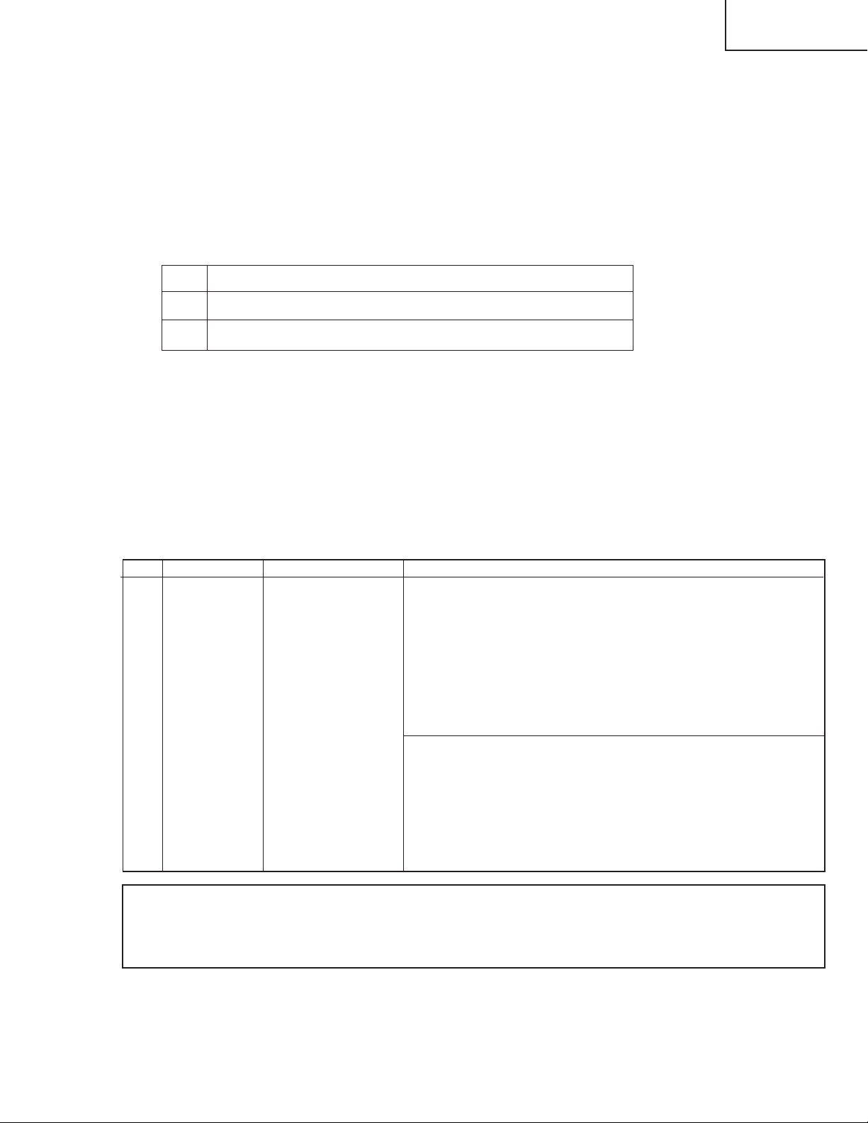
(6)Remote control
Key Function
1 Low-side pattern display (according to low adjustment values)
2 High-side pattern display (according to high adjustment values)
Press the same key again to hide the pattern.
Examples:
"1" key → Low-side pattern display → "1" key → Pattern hiding
"2" key → Low-side pattern display → "2" key → High-side pattern display → "2" key → Pattern hiding
LC-26D4U
LC-32D4U
LC-37D4U
10. Initialization to factory settings
Caution: When initialization is performed, all user setting data including the channel settings are initialized. Be cautious when making this adjustment.
(The adjustments done in the adjustment process mode are not initialized.)
Adjustment item Adjustment conditions Adjustment procedure
1 Initialization It turns off with AC pow-
er supply.
Enter the adjustment process mode.
Bring the cursor on to [INDUSTRY INIT] in page 2/14.
Set to [ON] using [VOL] key, and press [ENTER] to execute the
initialization.
When the initialization is complete, the adjustment process mode screen is
automatically replaced by the TV's 1ch screen.
* Never shut off the power during the initialization process.
The following settings are initialized in this adjustment.
1. User setting
2. Channel data (e.g. broadcast frequencies)
3. Password data
4. Operation time
5. Maker's optional setting
6. Auto installation flag
7. V-CHIP block setting
After the adjustment, cancel the adjustment process mode.
To exit the adjustment process mode, unplug the AC power cable from the outlet to make a forced
shutdown. (When the power was turned off with the remote controller, once unplug the power cable
and plug it again. In this case, wait 10 seconds or so before plugging.)
31
Page 32

LC-26D4U
LC-32D4U
LC-37D4U
11. Display adjustment procedure
1. Entering and exiting the adjustment process mode
(1) Before entering the adjustment process mode, press the "RESET" button or execute the AV position
RESET in the menu video adjustment.
(2) While holding down the "VOL (+)" and "CH (Ù)" keys at a time, plug in the AC cord of the main unit to
turn on the power.
(The VOL "(+)" and "CH (Ù)" keys should be pressed and held until the display appears.)
The letter " <K> " appears on the screen.
(3) Next, press the remote controller key (VOL, CH, etc.).
Multiple lines of blue characters appearing on the display indicate that the unit is now in the adjustment
process mode.
When you fail to enter the adjustment process mode (the display is the same as normal startup), retry
the procedure.
(4) To exit the adjustment process mode after the adjustment is done, unplug the AC cord from the outlet to
make a forced shutdown. (When the power was turned off with the remote controller, once unplug the
AC cord and plug it again. In this case, wait 10 seconds or so before plugging.)
Caution: Use due care in handling the information described here lest your users should know
how to enter the adjustment process mode. If the settings are tampered in this mode,
unrecoverable system damage may result.
2. Adjustment process mode key operation table
Key Function 1 (when on the left side of a page) Function 2 (when changing a numeric value)
Cursor UP
Cursor DOWN
Cursor RIGHT
Cursor LEFT
ENTER
INPUT
CH (ù)
CH (Ù)
VOL (+)
VOL (–)
Moving up by one item or moving to the previous
page (when at the top)
Moving down by one item or moving to the next
page (when at the bottom)
Moving to the right by one item or moving to
another page (in the case of the initial page)
Moving to the left by one item or moving to
another page (in the case of the initial page)
Test pattern off
Moving to the next page
Moving up by one item or moving to the previous
page (when at the top)
Moving down by one item or moving to the next
page (when at the bottom)
Moving to the right by one item or moving to
another page (in the case of the initial page)
Moving to the left by one item or moving to
another page (in the case of the initial page)
Incrementing the adjustment value by one or
executing the item (in the case of W or R item)
Decrementing the adjustment value by one or
executing the item (in the case of W or R item)
Moving to the right by one item
Moving to the left by one item
Executing the item (in the case of W or R item)
Moving to the next page
Incrementing the adjustment value by one or
executing the item (in the case of W or R item)
Decrementing the adjustment value by one or
executing the item (in the case of W or R item)
Moving to the right by one item
Moving to the left by one item
32
Page 33

3. Lamp error detection
3-1. Feature description
This liquid-crystal color TV incorporates a lamp error detection feature (lamp error detection) that automatically turns OFF the power for safety under abnormal lamp or lamp circuit conditions.
If anything is wrong with the lamp or lamp circuit or when the lamp error detection feature is activated for
some reason, the following will result.
1 The power of TV main body is turned OFF about six seconds after it is turned ON. (The power LED on
the front of the TV turns red from green and keeps blinking in red (ON for 240ms and OFF for 1sec)).
2 If occurs five times consecutively, it becomes impossible to turn ON the power. (The power LED keeps
blinking in red (ON for 240ms and OFF for 1sec)).
3-2. Measures
1) Checking with lamp error detection OFF
While the POWER switch is off, hold down the "CH (Ù)" and "VOL (+)" keys and then turn the POWER
switch on. The display will run in the "Display process mode" ("<K>" will appear).
If there is a problem with a lamp or a lamp circuit, the lamp will go out. (The power LED is green.)
Then, you can check the operation to see if the lamp and lamp circuit are abnormal.
2) Resetting the lamp error count
After you have finished checking whether the lamp and lamp circuit are abnormal, reset the lamp error
count. If a lamp error is detected five consecutive times, the power cannot be turned on.
Therefore, move to the [L ERR RESET] line, the 5th line on the first page of the "Display process mode",
using the Cursor UP/DOWN key. Then, reset the [L ERR RESET] value using the Cursor RIGHT/LEFT
key. In this case, press the Cursor UP/DOWN key to reset it to "0".
LC-26D4U
LC-32D4U
LC-37D4U
Table of contents of adjustment process mode Page 0
0123456789ABCDEF
0 SERV ICE I 2D4U3
1GRAYLEVEL 100
→
2COMBIAS 185
3VLSBIAS 041
4LERRRESET 5
5LCD
6PATTERN
7MOTORAND FAN
8OTHER
9 VER M803
After resetting to "0", perform an operational check to ensure that the lamp error detection feature is not activated.
Values specific to each display
Reset to "0
"
33
Page 34

LC-26D4U
LC-32D4U
LC-37D4U
6. List of adjustment process modes (Display)
(Examples)
34
Page 35

LC-26D4U
LC-32D4U
LC-37D4U
35
Page 36

LC-26D4U
LC-32D4U
LC-37D4U
First layer Page Item Setting range Initial value
Table of contents 0 GRAYLEVEL 0 ~ 255 25
COM BIAS 0 ~ 255 126
VLS BIAS 0 ~ 255 23
L ERR RESET Totally clear 0
LCD 1 MODE 50Hz,60Hz,PC 60Hz
PWM CTRL 0 ~ 7 7
PWM FREQ 0 ~ 4095 1289
PWM DUTY1 0 ~ 4095 0
PWM DUTY2 0 ~ 4095 0
PHASEDIF 0 ~ 255 0
2 MODE 50Hz,60Hz,PC 60Hz
QS SW 0 ~ 1 0
QS D1 0 ~ 255 110
QS D2 0 ~ 255 123
QS D3 0 ~ 255 135
QS D4 0 ~ 255 135
QS D5 0 ~ 255 167
QS D6 0 ~ 255 174
QS D7 0 ~ 255 179
3 OPC 0 0 ~ 85 0
OPC 1 0 ~ 85 11
OPC 2 0 ~ 85 21
OPC 3 0 ~ 85 30
OPC 4 0 ~ 85 38
OPC 5 0 ~ 85 45
OPC 6 0 ~ 85 51
OPC 7 0 ~ 85 56
OPC 8 0 ~ 85 61
4 OPC 9 0 ~ 85 66
OPC 10 0 ~ 85 70
OPC 11 0 ~ 85 73
OPC 12 0 ~ 85 76
OPC 13 0 ~ 85 79
OPC 14 0 ~ 85 81
OPC 15 0 ~ 85 83
OPC 16 0 ~ 85 85
5 VH 0 0 ~ 1023 124
VL 0 0 ~ 1023 904
VH 31 0 ~ 1023 359
VL 31 0 ~ 1023 598
VH 63 0 ~ 1023 397
VL 63 0 ~ 1023 579
VH 95 0 ~ 1023 416
VL 95 0 ~ 1023 551
6 VH 127 0 ~ 1023 454
VL 127 0 ~ 1023 517
VH 159 0 ~ 1023 485
VL 159 0 ~ 1023 486
VH 191 0 ~ 1023 538
VL 191 0 ~ 1023 538
VH 247 0 ~ 1023 1022
VL 247 0 ~ 1023 122
36
Page 37

<Power supply>
LC-26D4U
LC-32D4U
LC-37D4U
TROUBLE SHOOTING TABLE
The unit does not start even if the power is turned on (the front LED does not light up).
Is the power supply cord properly connected to the main unit?
YES
Are F701, F702, and F703 normal?
YES
Is the output voltage of BU+6V line (pin 5 of PO terminal) normal?
YES
Are the wire harness, FFC, etc. in the set connected properly?
YES
Is voltage (approx. 380V) generated at C709/C710/C832 (*3) when
powered on?
*3: for 37" only
YES
Is the 13V line normal immediately after powered on?
YES
NO
NO
NO
NO
NO
NO
Reconnect the power supply cord and turn on the power.
If fuses burn out when F701 and F702 are replaced and the
power is turned on again, replace VA702, VA703, D701, D796
(*1), L703, TH703 (*2), Q701, Q702, and IC701, and recheck
them.
*1: for 37" only *2: for 32/37" only
In stand-by, is a voltage of about 170 V applied to C734?
YES
Check the oscillation side (primary side) and the commutation
side (secondary side) of the BU6V system power supply circuit.
YES
Is there any broken part or short-circuit on BU6V line?
YES
Remove the broken part or short-circuit and check again.
Reconnect the wire harness, FFC, etc. and check again
Check the switching power supply circuit of 380V system.
(L703, IC701, Q701-5, Q715, Q716, D705, D797 (*4), TH701, etc.)
*4: for 37" only
Check the switching power supply circuit of 13V line.
(T701, T702, Q706-714, PC703-704, D708-716, IC702, L709,
Q733-736, D734-735, etc.)
.
Is each DC/DC converter output normal?
YES
Replace each DC/DC converter. Check peripheral circuits and
each line.
1) URB6V(IC707) 4) BS10V(IC708)
2) UR10V/UR31V(IC709) 5) UR6V/5V (IC707, IC713)
3) 1.8V/3.3V (IC711, IC710)
• Power switch: Top panel
(Main) Power (DC cutoff: Detected by microprocessor)
[Scheme of power supply system]
PS-ON
[(Main) Power OFF sequence]
NO
Seine
Main
Monitor microprocessorBackup
Check the oscillator side for each DC/DC converter and rectifier
side on the secondary side.
POWER-KEY
37
Page 38

LC-26D4U
NO
NO
NO
NO
NO
NO
YES
YES
YES
YES
YES
YES
YES
YES
YES
YES
YES
No sound comes out. (1)
No sound comes out at UHF/VHF reception.
Is the SIF output from the tuner as
specified?(TU1101_Pin7)
Are the audio outputs (A-OUT_L/R) from pins (28)
and (29) of IC2702 as specified?
Is the audio input from pins (28) and (29) of
IC2702 to pins (11) and (15) of IC2502 (STEREO
AMP) normal?
Is the audio output from IC2502 normal?
Is the speaker switching relay (RY2501) normal?
YES
Check the connector (SP_P2501) of AV_UNIT and
periphery of speaker.
Are the audio signals from pins (34) and (33)
(SC2_OUTL/R) of IC2501 to pins (32) and (33) of
IC2702 (DIR) as specified?
Is the input signal to pin (67) (SOUNDIF1) of
IC2501 (MULTI_SOUND_PROCESSOR) as
specified?
Check tuner and its peripheral circuits.
No external input sound comes out.
Are the audio signals inputted to pins (56) (L-ch) and (57) (R-ch) of IC2501?
Is the L-ch audio signal outputted to pin (15) of IC3805?
Is the R-ch audio signal outputted to pin (11) of IC3805?
<INPUT-1>
Is the L-ch audio signal inputted from pin (5) of input terminal J1101 to pin (13) of IC3805?
Is the R-ch audio signal inputted from pin (2) of input terminal J1101 to pin (9) of IC3805?
<INPUT-2>
Is the L-ch audio signal inputted from pin (6) of input terminal J1101 to pin (3) of IC3805?
Is the R-ch audio signal inputted from pin (3) of input terminal J1101 to pin (7) of IC3805?
<INPUT-3>
Is the L-ch audio signal inputted from pin (5) of input terminal J1106 to pin (1) of IC3805?
Is the R-ch audio signal inputted from pin (2) of input terminal J1106 to pin (6) of IC3805?
<INPUT-4>
Is the L-ch audio signal inputted from pin (2) of input terminal J1900 to pin (5) of IC3805?
Is the R-ch audio signal inputted from pin (3) of input terminal J1900 to pin (8) of IC3805?
<INPUT-5>
Is the digital audio signal (HDMI_SPDIF) inputted from pin (29) of IC1912 to pin (43) of IC2702?
Check the peripheral circuits of filter circuits
(Q1145, Q1105-6).
Check IC2702 and its peripheral circuits.
Check IC2502 and its peripheral circuits.
Check circuits from pins (28) and (29) of IC2702 to
pins (11) and (15) of IC2502. (MUTE circuit:
Q2515-7)
Are signals LRCK, BICK, SDTO and SDTI
inputted/outputted from IC2702 to IC2700 (DSP)
normally?
Check the lines from pins (34) and (33)
(SC2_OUTL/R) of IC2501 to pins (32) and (33) of
IC2702.
NO
NO
YES
YES
No audio output when receiving digital
broadcasting
Is audio signal supplied to pins (53) and (54)
(SC2_IN_L/R) of IC2501?
Is analog audio signal supplied from the digital unit
to pins (11) and (9) of AV_UNIT connector (DA,
P1105)?
Check the digital unit.
Check between P1105 and IC2501.
LC-32D4U
LC-37D4U
TROUBLE SHOOTING TABLE (Continued)
38
Page 39
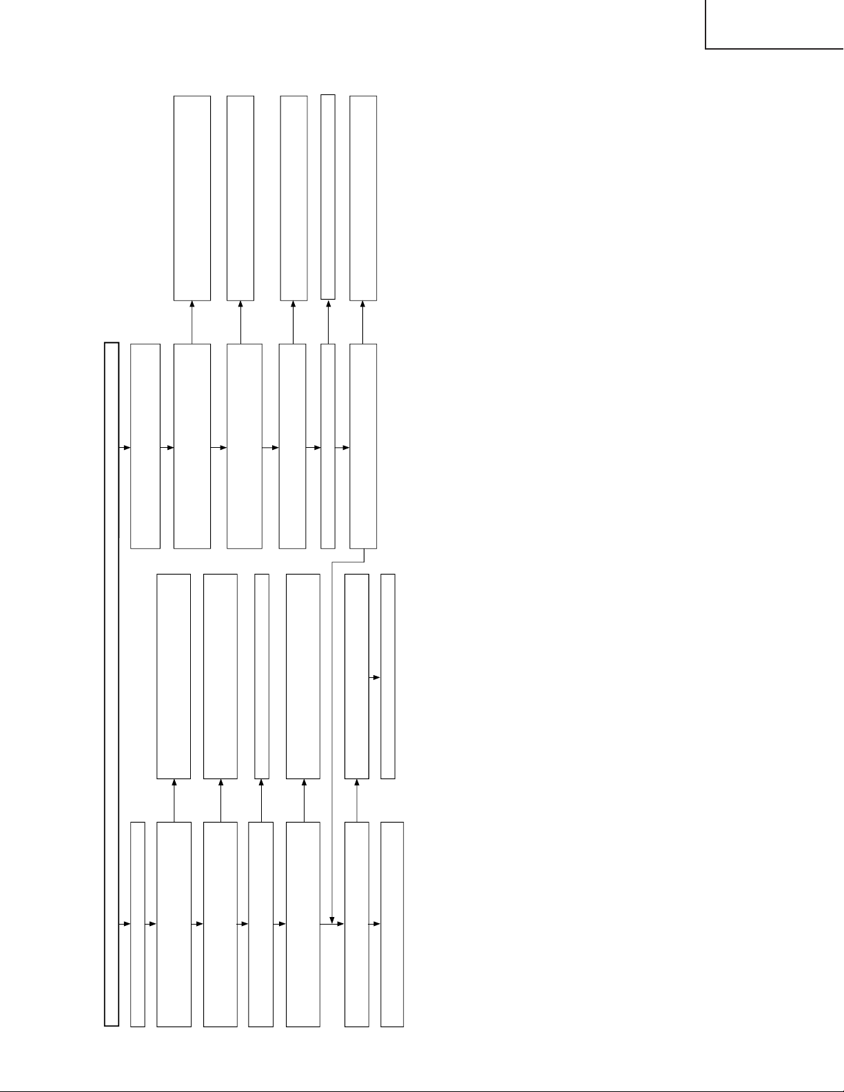
TROUBLE SHOOTING TABLE (Continued)
YES
YES
YES
YES
YES
NO
NO
NO
NO
No monitor audio output when receiving digital
broadcasting
Does IC5708 (AUD_AMP) function well?
Check the digital unit.
Check IC5704 and its peripheral circuits.
NO
Check between P3101 and IC1108.
(Q1107, Q1108, etc.)
Check IC5708 and its peripheral circuits.
Check from the connector (DS, P3101) of
AV_UNIT to the periphery of IC5704.
Is digtal audio signal supplied from the digital unit
to pins (4) and (7) of AV_UNIT connector (DS,
P3101)?
Are the analog-converted audio signals outputted
to output terminal pins (11) and (8) of IC5704?
Are audio signals supplied to the input terminal
pins (1)/(4) and (11)/(12) of IC1108?
Are signals I2SLRCLK, I2CDATA, I2SSCLK and
AUDMCLK inputted to the input terminals (pins (1)
to (4)) of IC5704 (DAC)?
NO
YES
NO
NO
NO
YES
NO
YES
YES
YES YES
YES
No sound comes out. (2)
Are audio output pins (37) and (36)
(SC1_OUT_L/R) of IC2501 (MULTI_SOUND_
PROCESSOR) as specified?
Are audio output pins (7) and (1) of IC2504
(EQ_AMP) as specified?
Are audio output pins (3) and (13) of IC1108 as
specified?
Check the line from IC1108 to the MONITOR
OUTPUT (J1106) terminal.
Are the audio signals inputted to input terminal
pins (2) and (5 ) and pins (14) and (15) of IC1108
(AUDIO_SW)?
No monitor audio output comes out.
Is the audio output of monitor output set to
"Variable"?
Check IC2501 and its peripheral circuits.
Reset the audio output of monitor output to
"Fixed".
Check IC2504 and its peripheral circuits.
Check the line from IC2504 to IC1108.
Check IC1108 and its peripheral circuits.
Is the control signal inputted to pin (10) of IC1108
as specified?
LC-26D4U
LC-32D4U
LC-37D4U
39
Page 40

LC-26D4U
YES
YES
YES
YES
YES
YES
YES
YES
NO
NO
YES
YES
NO
NO
NO
NO
NO
NO
YES
NO
NO
NO
<Signals>
No video output (1)<Composite video signal> input
External input in trouble <INPUT-1>
Is INPUT 1 selected in the input switching
menu screen?
Is video signal detection functioning
normally? Check between pin (11) of J1101
and pin (9) of IC1102.
Check between pin (8) of J1101 and pin (65)
of IC3800.
Select INPUT 1 and the input signal in the
input switching menu screen.
When it cannot be selected since the characters
INPUT-1 on the menu screen are gray.
Is video signal detection functioning
normally? Check between pin (10) of J1101
and pin (11) of IC1102.
Check between pin (9) of J1101 and pin (71)
of IC3800.
Check IC3800 (AV SWITCH) and the
peripheral circuits.
Select INPUT 2 and the input signal in the
input switching menu screen.
When it cannot be selected since the characters
INPUT-2 on the menu screen are gray.
Is there video signal input at pin (65) of
IC3800 (AV SWITCH)?
Is video signal supplied to pin (22) of MAIN_UNIT connector (FD_SC3201)?
Is video signal supplied to pin (85) of IC400 (3D-YC & CHROMA) through L.P.F. consisting of Q411 and Q412?
Are there digital video signal inputs at pins (53), (54), (57)~(60), (51), (52) (RE0-7), pins(63)~(68), (61), (62) (GE0-7), pins (73)~(78), (69),
(70) (BE0-7), pins (81)~(86), (79), (80) (RO0-7), pins (91)~(96), (89), (90) (GO0-7), pins (99), (100), (1), (2), (5), (6), (97), (98) (BO0-7), and
pins (7)~(10) (HSYNC, VSYNC, DE, CLKIN) of IC3201 (LVDS TRANSMITTER)?
Are there digital video signal outputs at pins (49)(TA1–), (48)(TA1+), (47)(TB1–), (46)(TB1+), (44)(TC1–), (43)(TC1+),(41)(TCLK–),
(42)(TCLK+), (40)(TD1–), (39)(TD1+), (37)(TA2–), (36)(TA2+), (35)(TB2–), (34)(TB2+), (32)(TC2–), (31)(TC2+), (30)(TCLK2–),(29)(TCLK2+),
(28)(TD2–), and (27)(TD2+) of IC3201?
Is INPUT 2 selected in the input switching
menu screen?
Is there video signal input at pin (71) of
IC3800 (AV SWITCH)?
Are there VIDEO signal output at pin (60) of IC3800?
Is video signal sent to pin (12) of AV_UNIT connector (FD_SC5701)?
External input in trouble <INPUT-2>
Check between IC3800 and SC5701.
(Q3802, Q3810, etc.)
Check the FFC harness "FD".
Check between IC3800 and IC400.
(Q3802, Q3810, Q411, Q412, etc.)
Are digital video signals sent from pins (43), (44), (46)-(49), (54), (55) and (58) of IC400?
Check IC400 and its peripheral circuits.
Replace the main PWB, or check between
IC400 and IC3201.
Check IC3201 (LVDS TRANSMITTER) and
the peripheral circuits.
Check the LCD CONTROL PWB.
LC-32D4U
LC-37D4U
TROUBLE SHOOTING TABLE (Continued)
40
Page 41
TROUBLE SHOOTING TABLE (Continued)
YES
YES
YES
YES
NO
NO
NO
YES
YES
YES
YES
YES
YES
NO
NO
NO
NO
NO
NO
NO
NO
NO
YES
YES
YES
YES
YES
NO
NO
External input in trouble <INPUT-3>
Is INPUT-3 selected in the input switching
menu screen?
Is there signal input at each input pin of
IC3800 (AV SWITCH)?
<Composite video signal input>
Is there signal input at pin (3)?
<S-video signal input>
Are there Y-signal input at pin (5) and C-
signal input at pin (7)?
Select INPUT 3 and the input signal in the
input switching menu screen.
When it cannot be selected since the characters
INPUT-3 on the menu screen are gray.
Is video signal detection functioning
normally? Check between pin (11) of
J1106 and pin (12) of IC1102.
Is S-video signal detection functioning
normally? Check between pin (6) of J1105
and pin (6) of IC3800.
Check between pin (8) of J1106 and pin (3)
of IC3800.
Check between pins (3), (4) of J1105 and
pins (5), (7) of IC3800.
<Composite video signal / S-video signal> input
<Composite video signal input> Are there VIDEO signal output at pin (60)?
<S-video signal input> Are there Y-signal output at pin (60) and C-signal output at pin (59) of IC3800?
<Composite video signal input> Is video signal sent to pin (12) of AV_UNIT connector (FD_SC5701)?
<S-video signal input> Are Y and C signals sent to pins (12) and (10) of AV_UNIT connector (FD_SC5701) respectively?
Are digital video signals sent from pins (43), (44), (46)-(49), (54), (55), (58) etc. of IC400?
No video output (2) No video output when receiving UHF/VHF broadcasting
Is there video signal output at output pin
(17) of the tuner (TU1101)?
Are there video signal inputs at pin (7) of
IC1103 (LEVEL ADJ)?
Is tuner video signal supplied to pin (17) of
IC3800 (AV SWITCH)?
Check or replace the tuner's peripheral
circuits.
Are there inputs of level adjustment control
signals at pin (6) of IC1103
(LEVEL ADJ) from pin (1) of IC1105?
Check IC1105 (CONTROL) and the peripheral
circuits. Replace if necessary.
No video output when receiving digital broadcasting (4)
Is video signal from the digital unit
supplied to AV_UNIT connector (DA,
P1105)?
Check the digital unit.
Is DTV video signal supplied to pin
(15) of IC3800 (AV SWITCH)?
Check between P1105
and IC3800. (Q1120,
Q1122, etc.)
Check IC3800 (AV SWITCH) and the
peripheral circuits.
Check between IC3800 and SC5701.
(Q3802, Q3810, etc.)
Are there digital video signal inputs at pins (53), (54), (57)~(60), (51), (52) (RE0-7), pins(63)~(68), (61), (62) (GE0-7), pins (73)~(78), (69), (70) (BE0-7), pins
(81)~(86), (79), (80) (RO0-7), pins (91)~(96), (89), (90) (GO0-7), pins (99), (100), (1), (2), (5), (6), (97), (98) (BO0-7), and pins (7)~(10) (HSYNC, VSYNC, DE,
CLKIN) of IC3201 (LVDS TRANSMITTER)?
Are there digital video signal outputs at pins (49)(TA1–), (48)(TA1+), (47)(TB1–), (46)(TB1+), (44)(TC1–), (43)(TC1+), (41)(TCLK–), (42)(TCLK+), (40)(TD1–),
(39)(TD1+), (37)(TA2–), (36)(TA2+), (35)(TB2–), (34)(TB2+), (32)(TC2–), (31)(TC2+), (30)(TCLK2–),(29)(TCLK2+), (28)(TD2–), and (27)(TD2+) of IC3201?
Check IC400 and its peripheral circuits.
<Composite video signal input> Is video signal supplied to pin (85) of IC400 (3D-YC & CHROMA) through L.P.F. consisting of Q411 and Q412?
<S-video signal input> Are Y and C video signals supplied to pins (85) and (90) of IC400 (3D-YC & CHROMA) through L.P.F. consisting of Q411 and Q412 and L.P.F.
consisting of Q415 and Q416 respectively?
Check between IC3800 and IC400.
(Q3802, Q3810, Q411, Q412, etc.)/
(Q3801, Q3811, Q415, Q416, etc.)
<Composite video signal input> Is video signal sent to pin (22) of MAIN_UNIT connector (FD_SC3201)?
<S-video signal input> Are Y and C signals sent to pins (22) and (24) of MAIN_UNIT connector (FD_SC3201) respectively?
Check the FFC harness "FD".
Replace the main PWB, or check between
IC400 and IC3201.
Check IC3201 (LVDS TRANSMITTER) and
the peripheral circuits.
Check the LCD CONTROL PWB.
LC-26D4U
LC-32D4U
LC-37D4U
41
Page 42

LC-26D4U
YES
YES
YES
YES
NO
NO
NO
YES
YES
NO
NO
YES
NO
YES
NO
YES
NO
YES
NO
YES
NO
YES
NO
YES
NO
NO
<Component video signal> input No video output (5)
External input in trouble <INPUT-1>
Is INPUT 1 selected in the input switching
menu screen?
Select INPUT 1 and the input signal in the
input switching menu screen.
When it cannot be selected since the characters
INPUT-1 on the menu screen are gray.
Is the detection function of component
video signal normal? Check between pin
(11) of J1107 and pin (78) of IC2501
(MULTI_SOUND_PROCESSOR).
Are component video signals supplied to
pins (21) (Y), (23) (PB), and (25) (PR) of
IC3800 (AV SWITCH)?
Check between J1107 and each input pin of
IC3801.
Are Y, PB and PR signals sent to pins (60), (59) and (58) of IC3800 respectively?
External input in trouble <INPUT-2>
Is INPUT 2 selected in the input switching
menu screen?
Select INPUT 2 and the input signal in the
input switching menu screen.
When it cannot be selected since the characters
INPUT-2 on the menu screen are gray.
Is component video signal detection
functioning normally? Check between pin (10)
of J1107 and pin (76) of IC3800 (AV SWITCH).
Are there signal inputs at pins (27), (29) and
(31) (Y, PB, PR) of IC3800 (AV SWITCH)?
Check between J1107 and each input pin
of IC3801.
Check IC3800 and its peripheral circuits.
Are component video signals supplied to pins (1), (5) and (25) of IC3703 (L.P.F) ?
Check between IC3800 and IC3703.
(Q3800-2, Q3810-12, etc.)
Are component video signals sent to pins (14), (11) and (17) of IC3703?
Check IC3703 and its peripheral circuits.
Are component video signals sent to pins (12), (10) and (8) of AV_UNIT connector (FD_SC5701)?
Check between IC3800 and SC5701.
(Q3802, Q3810, etc.)
Are component video signals supplied to pins (22), (24) and (26) of MAIN_UNIT connector (FD_SC3201)?
Check the FFC harness "FD".
Are component video signals supplied to pins (13) (GAIN0), (20) (BAIN0) and (5) (RAIN0) of IC3700 (A/D_CONV.)?
Check between IC3703 and IC3700.
Are digital video signals sent from pins (97)-(90), (87)-(80), (77)-(70), (64)-(57), (120)-(113), etc. of IC3700?
Check IC3700 and its peripheral circuits.
Replace the main PWB, or check between
IC3700 and IC3201.
Check IC3201 (LVDS TRANSMITTER) and
the peripheral circuits.
Are there digital video signal outputs at pins (49)(TA1–), (48)(TA1+), (47)(TB1–), (46)(TB1+), (44)(TC1–), (43)(TC1+), (41)(TCLK–), (42)(TCLK+), (40)(TD1–),
(39)(TD1+), (37)(TA2–), (36)(TA2+), (35)(TB2–), (34)(TB2+), (32)(TC2–), (31)(TC2+), (30)(TCLK2–),(29)(TCLK2+), (28)(TD2–), and (27)(TD2+) of IC3201?
Are there digital video signal inputs at pins (53), (54), (57)~(60), (51), (52) (RE0-7), pins(63)~(68), (61), (62) (GE0-7), pins (73)~(78), (69), (70) (BE0-7), pins
(81)~(86), (79), (80) (RO0-7), pins (91)~(96), (89), (90) (GO0-7), pins (99), (100), (1), (2), (5), (6), (97), (98) (BO0-7), and pins (7)~(10) (HSYNC, VSYNC, DE,
CLKIN) of IC3201 (LVDS TRANSMITTER)?
Check the LCD CONTROL PWB.
LC-32D4U
LC-37D4U
TROUBLE SHOOTING TABLE (Continued)
42
Page 43
TROUBLE SHOOTING TABLE (Continued)
No picture comes out. (6)
No monitor video output when receiving digital
broadcasting
YES
Is the video signal from the digital unit inputted
to the connectors (DA, P1105) Pin (7) of
AV_UNIT?
YES
Is the video signal inputted to the following
pins of IC1104 (AV_SW)?
<Composite video signal> Pin (8)
<S signal> Pin (11): SY-SUB, Pin (16): SCSUB
Is the video signal outputted to the following
pins of IC1104 (AV_SW)?
<Composite video signal> Pin (6)
<S signal> Pin (5): SY-SUB, Pin (3): SC-SUB
Check the monitor output terminals and their
peripheral circuits. (Q1113-5, Q1203-4,Q1148)
YES
YES
NO
NO
NO
Check the digital unit.
Check the line from P1105 to IC1104.
Check the control signals inputted to pins (2),
(7) and (12) of IC1104.
LC-26D4U
LC-32D4U
LC-37D4U
43
Page 44

LC-26D4U
LC-32D4U
LC-37D4U
1 Tip HDCP_LSI
TROUBLE SHOOTING TABLE (Continued)
No video signal from DVI input (digital) (1)
Are signals supplied from DVI
(SC1900) connector to input
terminals RX0 ± (pins 63 and 62),
RX1 ± (pins 67 and 66), RX2 ± (pins
71 and 70), and RXC ± (pins 59 and
58) of IC1912 (HDCP_LSI)?
YES
Are signals sent from Hsync (pin 2),
Vsync (pin 3) and RGB (pins 14, 17
and 20) of IC1912 ?
YES
No video signal from digital PC
NO YES
NO
Is IC1915 (E2PROM)
accessed with I2C when
connecting to PC and is
data read out?
Are the output pins (12)
and (14) of IC1917
(E2PROM) in (H, H)?
Do the output pins (12)
and (14) of IC1917
change to (L, L) when
setting to the analog AV
mode?
Check the I2C signal line (SCLB/SDAB) of pins (1)
and (2) of IC1917.
Check IC1912 and its
peripheral circuits.
No video signal from digital AV
Is IC1911 (E2PROM)
accessed with I2C when
connecting to PC and is
data read out?
NO
Are the output pins (12)
and (14) of IC1917 in (L,
H)?
NO
Do the output pins (12)
and (14) of IC1917
change to (H, L) when
setting to the analog PC
mode?
NO
YES
YES
Check PC settings.
Check IC1915 and its
peripheral circuits.
Check IC1917 and its
peripheral circuits.
Are DVI_SR/SG/SB and DVI_H/V
signals sent from pins (14), (16), (18),
(30) and (31) of AV unit connector
(SC5701) respectively?
YES
Are DVI_SR/SG/SB and DVI_H/V
signals supplied to pins (20), (18), (16),
(4) and (3) of main PWB connector
(SC3201) respectively?
YES
Are DVI_SR/SG/SB and DVI_H/V
signals supplied to pins (8), (17) and
(23) of IC3700 (A/D_CONV.) and pins
(3) and (13) of IC3701
(SYNC_SELECTER) respectively?
NO
Check IC1901, IC1903 and
their peripheral circuits.
NO
Check MD harness for
disconnection.
NO
Check IC3700, IC3701
and their peripheral
circuits.
44
Page 45

TROUBLE SHOOTING TABLE (Continued)
1 Tip HDCP_LSI
Are signals supplied from DVI
(SC1900) connector to IC1901?
Are signals supplied from DVI
(SC1900) connector to and input
terminals RGB (pins 1, 3 and 5) and
H.Vsync (pins 1 and 3) of IC1904?
YES
No video signal from DVI input (analog) (2)
No video signal from analog PC No video signal from analog AV
NO YES
Is IC1915 (E2PROM)
accessed with I2C when
connecting to PC and is
data read out?
Are the output pins (12)
and (14) of IC1917
(E2PROM) in (H, L)?
Is IC1911 (E2PROM)
accessed with I2C when
connecting to PC and is
data read out?
NO
Are the output pins (12)
and (14) of IC1917 in (L,
L)?
NO
YES
LC-26D4U
LC-32D4U
LC-37D4U
Check PC settings.
Check IC1915 and its
peripheral circuits.
Are there Vsync and Hsync signal
outputs at pins (4) and (6) of
IC1904(INVERTER)?
YES
Are DVI_SR/SG/SB and DVI_H/V
signals sent from pins (14), (16), (18),
(30) and (31) of AV unit connector
(SC5701) respectively?
YES
Are DVI_SR/SG/SB and DVI_H/V
signals supplied to pins (20), (18), (16),
(4) and (3) of main PWB connector
(SC3201) respectively?
YES
NO
NO
NO
Do the output pins (12)
and (14) of IC1917
change to (L, H) when
setting to the digital AV
mode?
Check the I2C signal line (SCLB/SDAB) of pins (1) and
(2) of IC1917.
Check IC1904 and its
peripheral circuits.
Check IC1901, IC1903 and
their peripheral circuits.
Check MD harness for
disconnection.
Do the output pins (12)
and (14) of IC1917
change to (H, H) when
setting to the digital PC
mode?
NO
YES
Check IC1917 and its
peripheral circuits.
Are DVI_SR/SG/SB and DVI_H/V
signals supplied to pins (8), (17) and
(23) of IC3700 (A/D_CONV.) and pins
(3) and (13) of IC3701
(SYNC_SELECTER) respectively?
NO
Check IC3700, IC3701
and their peripheral
circuits.
45
Page 46

LC-26D4U
LC-32D4U
LC-37D4U
TROUBLE SHOOTING TABLE (Continued)
1 Tip HDCP_LSI
Are signals supplied from HDMI (SC1901)
connector to input terminals H_RX0 ±
(pins 44 and 43), H_RX1 ± (pins 48 and
47), H_RX2 ± (pins 52 and 51), and
H_RXC ± (pins 40 and 39) of IC1912
(HDCP_LSI)?
YES
No HDMI input picture
Is IC1913 (E2PROM) accessed by I2C to
NO
read out DDC I2C CLOCK/DATA when
HDMI equipment is connected?
Check IC1913 and the peripheral
circuits.
Is there HDMI_RST signal output at
output pin (6) of IC1914 (EXPANDER)?
Check IC1914 and the peripheral
circuits.
NO
YES
NO
YES
YES
Check HDMI equipment settings.
Check IC1912 and the peripheral
circuits.
Are HDMI_Y/Pb/Pr and HDMI_H/V signals
sent from pins (26), (28), (24), (20) and
(22) of AV unit connector (SC5701)
respectively?
YES
Are HDMI_Y/Pb/Pr and HDMI_H/V signals
supplied to pins (8), (6), (10), (14) and (12)
of MAIN unit connector (SC3201)
respectively?
YES
Are HDMI_Y/Pb/Pr and HDMI_H/V signals
supplied to pins (3), (7), (27) of IC3703
(L.P.F.) and pins (4) and (12) of IC3701
(SYNC_SELECTER) respectively?
NO
Check IC1912 (HDCP_LSI) and the
peripheral circuits.
NO
Check FD harness for disconnection.
NO
Check IC3703, IC3701 and the
peripheral circuits.
46
Page 47

TROUBLE SHOOTING TABLE (Continued)
2 Tip HDCP_LSI
Are signals supplied from DVI
(SC1900) connector to input
terminals RX0 ± (pins 2 and 3), RX1
± (pins 51 and 52), RX2 ± (pins 48
and 49), and RXC ± (pins 5 and 6) of
IC1900 (HDCP_LSI)?
YES
No video signal from DVI input (digital) (1)
No video signal from digital PC No video signal from digital AV
NO YES
Is IC1915 (E2PROM)
accessed with I2C when
connecting to PC and is
data read out?
Are the output pins (12)
and (14) of IC1917
(E2PROM) in (H, H)?
Is IC1911 (E2PROM)
accessed with I2C when
connecting to PC and is
data read out?
NO
Are the output pins (12)
and (14) of IC1917 in (L,
H)?
NO
YES
LC-26D4U
LC-32D4U
LC-37D4U
Check PC settings.
Check IC1915 and its
peripheral circuits.
Are signals sent from Hsync (pin 18),
Vsync (pin 19) and RGB (pins 23, 26
and 31) of IC1900 ?
YES
Are DVI_SR/SG/SB and DVI_H/V
signals sent from pins (14), (16), (18),
(30) and (31) of AV unit connector
(SC5701) respectively?
YES
Are DVI_SR/SG/SB and DVI_H/V
signals supplied to pins (20), (18), (16),
(4) and (3) of main PWB connector
(SC3201) respectively?
YES
NO
NO
NO
Do the output pins (12)
and (14) of IC1917
change to (L, L) when
setting to the analog AV
mode?
Check the I2C signal line (SCLB/SDAB) of pins (1)
and (2) of IC1917.
Check IC1900 and its
peripheral circuits.
Check IC1901, IC1903 and
their peripheral circuits.
Check MD harness for
disconnection.
Do the output pins (12)
and (14) of IC1917
change to (H, L) when
setting to the analog PC
mode?
NO
YES
Check IC1917 and its
peripheral circuits.
Are DVI_SR/SG/SB and DVI_H/V
signals supplied to pins (8), (17) and
(23) of IC3700 (A/D_CONV.) and pins
(3) and (13) of IC3701
(SYNC_SELECTER) respectively?
NO
Check IC3700, IC3701
and their peripheral
circuits.
47
Page 48

LC-26D4U
LC-32D4U
LC-37D4U
TROUBLE SHOOTING TABLE (Continued)
2 Tip HDCP_LSI
Are signals supplied from DVI
(SC1900) connector to IC1901?
Are signals supplied from DVI
(SC1900) connector to input
terminals RGB (pins 1, 3 and 5) and
H.Vsync (pins 1 and 3) of IC1904?
YES
No video signal from DVI input (analog) (2)
No video signal from analog PC No video signal from analog AV
NO
Is IC1915 (E2PROM)
accessed with I2C
when connecting to PC
and is data read out?
Are the output pins (12)
and (14) of IC1917
(E2PROM) in (H, L)?
Is IC1911 (E2PROM)
accessed with I2C
when connecting to PC
and is data read out?
NO
Are the output pins (12)
and (14) of IC1917 in
(L, L)?
NO
YES
YES
Check PC settings.
Check IC1915 and its
peripheral circuits.
Are there Vsync and Hsync signal
outputs at pins (4) and (6) of IC1904
(INVERTER)?
YES
Are DVI_SR/SG/SB and DVI_H/V
signals sent from pins (14), (16), (18),
(30) and (31) of AV unit connector
(SC5701) respectively?
YES
Are DVI_SR/SG/SB and DVI_H/V
signals supplied to pins (20), (18),
(16), (4) and (3) of main PWB
connector (SC3201) respectively?
YES
NO
NO
NO
Do the output pins (12)
and (14) of IC1917
change to (L, H) when
setting to the digital AV
mode?
Check the I2C signal line (SCLB/SDAB) of pins (1)
and (2) of IC1917.
Check IC1904 and its
peripheral circuits.
Check IC1901, IC1903 and
their peripheral circuits.
Check MD harness for
disconnection.
Do the output pins (12)
and (14) of IC1917
change to (H, H) when
setting to the digital PC
mode?
NO
YES
Check IC1917 and its
peripheral circuits.
Are DVI_SR/SG/SB and DVI_H/V
signals supplied to pins (8), (17) and
(23) of IC3700 (A/D_CONV.) and pins
(3) and (13) of IC3701
(SYNC_SELECTER) respectively?
NO
Check IC3700, IC3701
and their peripheral
circuits.
48
Page 49

TROUBLE SHOOTING TABLE (Continued)
2 Tip HDCP LSI
Are signals supplied from HDMI (SC1901)
connector to input terminals H_RX0 ±
(pins 87 and 86), H_RX1 ± (pins 92 and
91), H_RX2 ± (pins 97 and 96), and
H_RXC ± (pins 84 and 83) of IC1912
(HDCP_LSI)?
YES
NO
No HDMI input picture
Is IC1913 (E2PROM) accessed by I2C to
read out DDC I2C CLOCK/DATA when
HDMI equipment is connected?
NO
Check IC1913 and the peripheral
circuits.
YES
Is there HDMI_RST signal output at
output pin (6) of IC1914 (EXPANDER)?
NO
Check IC1914 and the peripheral
circuits.
YES
YES
LC-26D4U
LC-32D4U
LC-37D4U
Check HDMI equipment settings.
Check IC1912 and the peripheral
circuits.
Are HDMI_Y/Pb/Pr and HDMI_H/V
signals sent from pins (26), (28), (24),
(20) and (22) of AV unit connector
(SC5701) respectively?
YES
Are HDMI_Y/Pb/Pr and HDMI_H/V
signals supplied to pins (8), (6), (10),
(14) and (12) of MAIN unit connector
(SC3201) respectively?
YES
Are HDMI_Y/Pb/Pr and HDMI_H/V
signals supplied to pins (3), (7), (27) of
IC3703 (L.P.F.) and pins (4) and (12) of
IC3701 (SYNC_SELECTER)
respectively?
NO
NO
NO
Check IC1912 (HDCP_LSI) and the
peripheral circuits.
Check FD harness for disconnection.
Check IC3703, IC3701 and the
peripheral circuits.
49
Page 50

LC-26D4U
LC-32D4U
LC-37D4U
TROUBLE SHOOTING TABLE (Continued)
No sound or picture comes out.
Is the power LED lit up in blue? Is the power LED blinking in red?
YES
NO
YES
Blinking once? (At regular intervals)
NO
Check the power supply unit.
Check the power supply circuit.
CCKM and D5V line are in order.
NO
YES
Is the Backlight off?
To "The backlight does not go on."
YES
Blinking once?
NO
To "The backlight does not go on."
Blinking twice?
NO
Blinking five times?
NO
To "No picture comes out."
Table of power LED blinking timing at error occurrence
Type of error
Power supply error
Blinking once: Slow
Lamp error
Blinking once: Fast
Panel power supply error
(VSH) Blinking twice
In-set temperature error
Blinking five times
H: ON
L: OFF
H: ON
L: OFF
H: ON
L: OFF
H: ON
L: OFF
Check the panel power supply detection (VSH).
Check the temperature of the set.
250ms 1sec
Power LED operation (1 cycle)
YES
YES
YES
No picture comes out.
Is there the clock output at pin (40) of IC4601?
Does the adjustment process menu appear? Check IC4601 and its peripheral circuits.
Check IC4901 and its peripheral circuits.
Set PATTERN1 → PATTERN1 on the adjustment process menu
to "2". Is the gray scale pattern displayed correctly?
Set PATTERN1 → PATTERN3 on the adjustment process menu
to "2". Is the gray scale pattern displayed correctly?
Set PATTERN1 → PATTERN3 on the adjustment process menu
to "4". Is the test pattern displayed correctly at intervals of one
dot?
Set PATTERN1 → PATTERN3 on the adjustment process menu
to "5". Is the test pattern displayed correctly at intervals of one
dot?
Check the peripheral circuits of IC4601.
YES
Data dropout (relating to gray scale)
YES
YES
YES
YES
NO
NO
NO
NO
NO
NO
Check the FFC (LV, SC3200, SC4601) connections between the
main PWB and LCD control PWB.
Check the connection between SC4651 and SC4652 and check
the peripheral circuits of IC4501.
Check IC4902 and its peripheral circuits.
Check the line between IC4901 and IC4501.
Check the line between IC4901 and IC4501.
50
Page 51

TROUBLE SHOOTING TABLE (Continued)
Noise is caused to the moving picture with the QS drive on.
LC-26D4U
LC-32D4U
LC-37D4U
Is TEMP. AD on page 1 of process adjustment mode set to 255?
Is the harness connected correctly between the inverter GND
PWB and LCD control PWB?
Is the input voltage at pin (62) of IC2004 (microprocessor) 5V?
The thermistor on the inverter GND PWB is faulty.
Does the inverter oscillation circuit in the power supply unit
operate normally?
Has the fuse (F705) in the power supply unit burnt out?
Is pulse power supplied to the booster circuit on the inverter
PWB?
Check the booster circuit on the inverter PWB. Are circuits on the
inverter GND PWB and LCD control PWB normal?
Check the fluorescent lamps, connectors and peripheral circuits.
Is the gradation pattern displayed properly when setting
Adjustment process menu -> PATTERN1 -> PATTERN3 to "1"?
(Is it whitish or dark?)
Disconnect the FPC from SC4651 and SC4652. (To protect the
panel against damage)
Check of voltage supplied to the panel
YES
YES
YES
The backlight does not go on.
YES
NO
YES
YES
The whole screen is whitish (LCD power supply).
NO
YES
26" model 32"model 37"model
2pin: VH0 8.36 8.27 8.35
3pin: VH31 10.27 10.17 10.18
4pin: VH63 10.61 10.44 10.51
5pin: VH95 10.89 10.74 10.71
6pin: VH127 11.15 10.98 10.96
7pin: VH159 11.5 11.33 11.3
8pin: VH191 11.93 11.78 11.72
9pin: VH247 14.27 14.14 14.14
10pin: VH255 15.1 14.98 15.1
11 pin: VLS 15.4 15.4 15.4
30pin: VSH 3.3 3.3 3.3
64pin: VL0 7.4 7.29 7.35
63pin: VL31 5.48 5.38 5.45
62pin: VL63 5.07 5.00 5.04
61pin: VL95 4.76 4.72 4.72
60pin: VL127 4.44 7.37 4.42
59pin: VL159 4.04 4.00 4.07
58pin: VL191 3.55 3.52 3.64
57pin: VL247 0.98 0.98 0.91
56pin: VL255 0.2 0.2 0.2
76pin: VGH 32V-15V 32V-15V 32V-15V
78pin: VGL -6V -6V -6V
NO
NO
NO
NO
YES
NO
NO
YES
Check IC4901 and its peripheral circuits.
Connect the harness correctly or replace it.
Pin (62) of IC2004 (microprocessor) is faulty.
Check the inverter oscillation circuit.
Check the circuit behind the burnt fuse.
Check the connector (PG) connecting the power supply PWB and
inverter PWB.
Check each PWB circuit or harness.
Check the video signal circuit.
51
Page 52

LC-26D4U
LC-32D4U
LC-37D4U
MAJOR IC INFOMATIONS
● IC3800 (MM1630AQ)
Video switch controlled by I2C BUS to select 4 color difference signals (component signals), 5 S-video signals and
8 composite signals.
The analog video signal input from each input terminal and the tuner is sent to this IC and selected. The video output
signal output from here and the component video signal are input into the video decoder circuit IC400 with a builtin Y/C separation via the low-pass filter and into the A/D converter (AD988810) via the low-pass filter (IC5703),
respectively.
● IC3805 (NJM2750M)
4-input/1-output stereo audio selector.
Composed of switch operation amplifier and controlled by 2-input digital signals. The audio signal input from each
input terminal is sent to this IC and selected. The audio output signal output from here is fed to the digital amplifier
via IC2501 (SOUND PROCESSOR).
● IC400 (TC90A92A)
Video decoder IC with a built-in Y/C separation.
TC90A92A is the LSI in which Y/C separation function and a multi-system video decoder are integrated into one
chip.
10-bit and 8-bit ADCs for analog input interface and 4-Mbit memory for NTSC 3D Y/C separation are incorporated.
Chrominance demodulation is performed after Y/C separation, and the output interface is output digitally (601/656).
● IC3703 (SM5301AS)
Fifth order Butterworth low-pass filter with a sync clamp function.
The filter characteristics depend on the input video signals, and the cutoff frequency can be set randomly by DC
control voltage of the pin 21.
● IC3700 (AD988810)
A/D converter with built-in PLL AMP
After controlling level of analog RGB and HDMI Y/Cb/Cr input signals, A/D conversion is performed using the clock
generated by PLL to output signals at TTL level. Video signal sent to this IC is digitally converted and sent to IC801
[F.P.G.A. (Field Programmable Gate Arrays)].
● IC802 (IXA835WJ)
F.P.G.A. (Field Programmable Gate Arrays) for synchronous processing and signal selector of each digitalized input
signal.
● IC3300 (IXA091WJ)
Performs data conversion for video signal processing, such as I/P conversion and scaling, to fit digitalized video
signal to output resolution.
Output digital signal is sent to IC3201 (LVDS TRANSMITTER).
● IC3201 (THC63LVD823)
170 MHz LVDS (Low Voltage Differential Signaling) 24 bit interface chip set for transmission. It is an LSI for
serializing and transmitting RGB signals, HD/VD/blanking signals and pixel clocks.
LVDS is a method for transmitting high-speed digital signals via cables driven by low-amplitude differential signals.
1LINK consists of five pairs of differential signals. The TA, TB, TC, and TD pairs are used for data transmissions,
and the TCLK pair is used for pixel clock transmissions. Seven data bits of TA, TB, TC and TD each (28 in total)
are transmitted per pixel clock.
The input RGB (24 bit) signal and sync signal (HD, VD and DE) are allocated to these 28 data.
● IC4601 (IXB001WJ)
Input signal is Dual link LVDS with RGB of 8 bits each. Output signal performs CMOS output with RGB of 8 bits each,
sync signal (H, V, DE) synchronizing with the input signal and free running sync signal (H, V, DE) output.
● IC4602 (IXB272WJ)
EEPROM for storing 10-bit gamma correction and cross-talk correction data.
Data is read into IC4601 (IXB001WJ) on start-up.
52
Page 53

LC-26D4U
LC-32D4U
LC-37D4U
● IC4901 (IXB002WJ)
QS driver.
Performs the QS (Quick Shoot) drive for the input signal from the picture quality correction IC (IC4601:IXB001WJ),
according to the temperature parameter setting from monitor microprocessor, and outputs the LVDS signal. Also
controls FIFO (IC4902: RH-IXA986WJZZQ) used for calculation.
● IC4902 (IXA986WJ)
26-Mbit FIFO.
Memory for operation of IC4901 (IXB002WJ) QS driver IC.
● IC4903 (26: IXB243WJ / 32: IXB242WJ / 37: IXB228WJ)
EEPROM for storing QS parameters.
Data is read into QS driver on a frame-by-frame basis.
● IC4501 (IXB003WJ)
LCD controller.
Receives RGB signal of LVDS sent from the QS driver, and outputs image signal (RSDS) to LCD panel. This IC
controls dimmer and creates the control signal of the CS circuit.
● IC4101 (IXA706WJ)
Gradation reference power supply for TFT LCD. It incorporates a gradation output buffer amplifier 18 circuit, CMOS
buffer amplifier and reference voltage generator.
● IC2004 (IXA870WJ)
Microprocessor for LCD controller.
Performs OSD control of LCD monitor, detection of panel temperature by the thermistor, setting of temperature
parameter for the QS driver, timing for LCD controller, setting of dimmer data, power supply control, monitoring of
each power supply line, remote control decoding, and OPC control.
● IC2501 (IX3370CE/MSP3450G)
An IC for decoding voice data.
Decodes S-IF and simultaneously acts as a selector of inputted voice data.
● IC2702 (AK4586VQ)
24 bit CODEC with built-in 2CH ADC and 6CH DAC. (CODEC is a device that converts analog signal to digital bit
stream.)
It has a 96 kHz, 24 bit compatible built-in DIR (Digital audio receiver).
In addition, it automatically detects non-PCM data stream such as AC-3/MPEG.
CODEC is an electronic circuit, a type of AD/DA converter, that converts analog voice data to digital codes, and vice
versa.
● IC2700 (NJU26150)
Processor IC consisting of a 24 bit DSP (Digital Signal Processor) core with built-in DIR and various interfaces. It
is activated by downloading a program written on IC2706 (E
2
PROM) to the built-in PRAM.
The internal function is composed of sound delay, BBE and parametric equalizer, and performs digital processing
in the I2S format.
It has three input lines (SDI0, SDI1 and SDI2) and three output lines (SD00, SD01 and SD02). Two types of LR clock
(LRI and LRO) and BCK (BCKI and BCKO) establish data transfer on serial data lines.
● IC2701 (NJU26106)
Digital signal processor to decode matrix-encoded stereo signal (Lt/Rt). On this unit, it functions as the Dolby Virtual.
● IC2709 (AK4353)
96 kHz, 24 bit compatible stereo CMOS D/A converter with a built-in digital audio transmitter.
● IC1001 (IXB320WJ)
High performance CPLD (Complex Programmable Logic Device).
Communicates to the display section and operates the system.
It also controls ICs of the entire system.
53
Page 54

LC-26D4U
LC-32D4U
LC-37D4U
● IC3704 (TA1318AF)
IC for TV component signal synchronous processing and frequency counter.
It incorporates functions required for frequency measurement of input signals and for synchronous play in one chip.
It is compatible with horizontal synchronous play (15.75 kHz, 31.5 kHz, 33.75 kHz, 45 kHz) and vertical synchronous
play (525I, 525P, 625I, 750P, 1125I, 1125P, PAL100 Hz, NTSC 120 Hz).
● IC1912 (Sii9021) * 1 Tip: When using HDCP_LSI
Digital interface receiver with High-bandwidth Digital Content Protection (HDCP) composed of the dual-input type
TMDS (Transition-Minimized Differential Signaling).
Supports both HDMI (High-Definition Multimedia Interface) and DVI (Digital Visual Interface).
● IC1900 (Sii907) *2 Tip: When using HDCP_LSI
DVI receiver with the High-bandwidth Digital Content Protection (HDCP).
The HDCP decoding engine is compatible with the pixel-by-pixel method.
The I2C interface communicates with a host at 400 kHz using the slave I2C interface. The HDCP key is preprogrammed and authentication management is performed by reading/writing to the entry in SiI907 through I2C
interface.
The key cannot be read for safety.
● IC1912 (Sii9993) *2 Tip: When using HDCP_LSI
HDMI (High definition Multimedia Interface) is a digital interface which supports the digital video signal encryption
system "HDCP" and can transfer HD image and multi-channel audio by one cable.
Supports 24-bit RGB 4:4:4, 24-bit YCbCr 4:4:4, and 16/10/24-bit YCbCr 4:2:2.
54
Page 55

- M E M O -
LC-26D4U
LC-32D4U
LC-37D4U
55
Page 56

LC-26D4U
LC-32D4U
LC-37D4U
CHASSIS LAYOUT/OVERALL WIRING DIAGRAM
H
LC-26D4U
LC-32D4U
LC-37D4U
G
KEY UNIT
KM
1 5
FPC:QPWBMC494WJPZ FPC:QPWBMC494WJPZ
80
1 80
1
LCD CONTROL UNIT
LV SH
F
26D4U:QCNW-D776WJQZ
32D4U:QCNW-D776WJQZ
37D4U:QCNW-D777WJQZ
S-VIDEO
26D4U:QCNW-D771WJQZ
32D4U:QCNW-D779WJQZ
V-IN3
MON.-OUT
E
AV UNIT
COMP-1,2
V-IN1,2
D
26D4U:QCNW-D282WJQZ
32D4U:QCNW-D081WJQZ
37D4U:QCNW-D308WJQZ
C
LED UNIT
1 7
RA
DIGITAL
AUDIO
OUTPUT
U/V
TUNER
DIGITAL
TUNER SW
2RF(air/cable)
DS
14 1
RS-232C
CONTROL
2
DA
1
1
RA
7 1
37D4U:QCNW-D781WJQZ
1 12
PA
QCNW-D080WJQZ
SP
1 4
AUDIO
INPUT
HDMI
60
FFC
QCNW-
1
26D4U:QCNW-D774WJQZ
32D4U:QCNW-D775WJQZ
37D4U:QCNW-D775WJQZ
1 5
KM
QCNW-D187WJQZ
QCNW-D188WJQZ
1
60
30
1 30
LV
MAIN UNIT
7
1
26D4U:QCNW-D768WJQZ
32D4U:QCNW-D769WJQZ
37D4U:QCNW-D769WJQZ
SH
1 7
79 80
1 2
39 40
1 2
1
MI
14 1
DS
BOARD
To
BOARD
DIGITAL
26D4U:QCNW-D770WJQZ
32D4U:QCNW-D772WJQZ
37D4U:QCNW-D773WJQZ
1 12
DS
DA
79 80
1 2
39 40
1 2
TUNER
SD-CARD
POD
9
DP
1
9
DP
1
26D4U:QCNW-D819WJQZ
32D4U:QCNW-D820WJQZ
37D4U:QCNW-D821WJQZ
DIGITAL UNIT
19 20
1 2
PE
PD
PE
12
1
8
1
26D4U:QCNW-D787WJQZ
32D4U:QCNW-D788WJQZ
37D4U:QCNW-D822WJQZ
26D4U:QCNW-D778WJQZ
32D4U:QCNW-D784WJQZ
37D4U:QCNW-D780WJQZ
1
PA
12
POWER
UNIT
GT
1 2
PG1
PG2
AC IN
INVERTER
UNIT
1
CN7502
6
1
10
1
10
32D4U:QCNW-D782WJQZ
37D4U:QCNW-D783WJQZ
1
CN7501
10
外
1
販
ラ
イ
6
ン
用
B TO B
1
CN7601
10
To LAMP
To LAMP
To LAMP
To LAMP
To LAMP
To LAMP
To LAMP
To LAMP
26D4U:QCNW-D280WJQZ
B
32D4U:QCNW-D079WJQZ
37D4U:QCNW-D306WJQZ
SP-R
A
87109654321
1716 19181514131211
5756
Page 57

LC-26D4U
LC-32D4U
LC-37D4U
SYSTEM BLOCK DIAGRAM
H
G
F
LC-26D4U
LC-32D4U
LC-37D4U
E
D
C
B
A
87109654321
1716 19181514131211
5958
Page 58
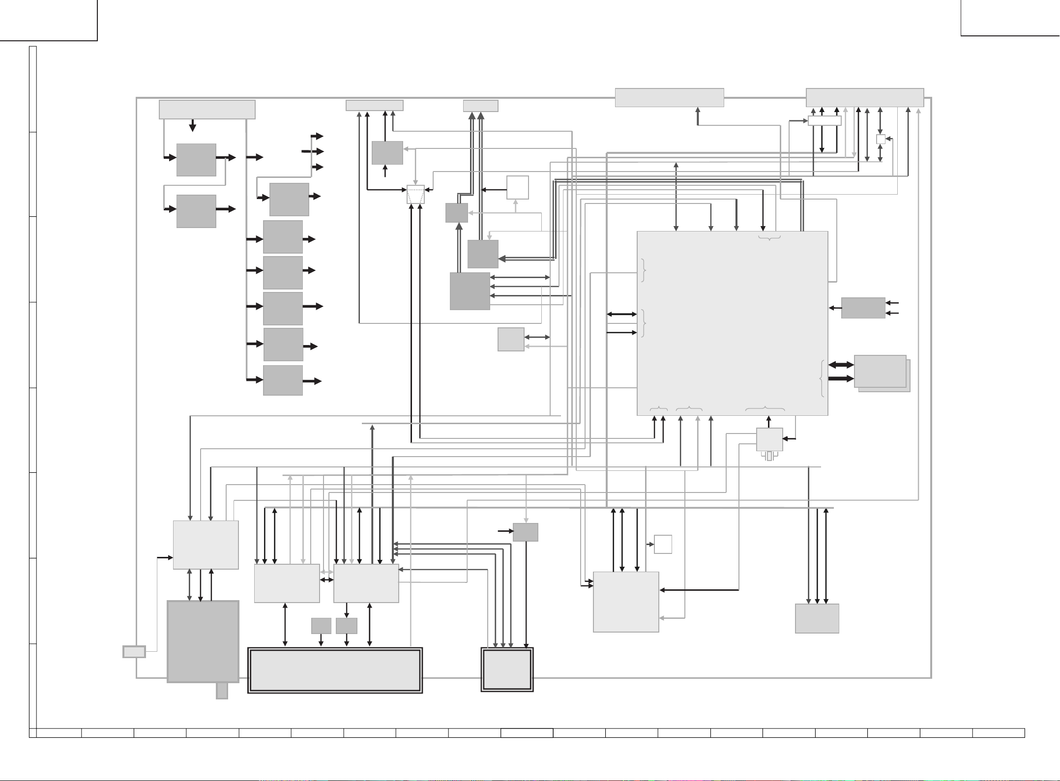
LC-26D4U
LC-32D4U
LC-37D4U
DIGITAL BLOCK DIAGRAM
LC-26D4U
LC-32D4U
LC-37D4U
SC5V
TA5V
A5V
A3V3
D3V3
D1V2
( -->
D2V5
( -->
DEMOD)
PH1)
P8801 (NA334WJ)
: Digital Audio Out /
User Serial / RF-SW
DS
RS_3V3
IC9007
PQ1X331M
SPDIF
3.3V
BU5V
RS_TXD, RS_RXD
RF_SW
RS_ON
N_SRESET
SW
UATXD1
UATXD0
P9601
H
(NA162WJ) : Power
DP
BU18V
BU5V(64mA)
(PQ1CZ41H)
5V(500mA)
G
(PQ1CX12H)
3.3V(1.3A)
F
E
IC9702
IC9701
VCC(10V)
P5V
P3V3
IC9602
(PQ1CZ41H)
5V(500mA)
IC9608
(PQ1M335M)
3.3V
IC9605
(PQ090DNA)
9V(32mA)
IC9601
(PQ1CZ41H)
3.3V
IC9603
(TPS54350)
1.2V
IC9606
(MP1571DS)
1.1V
IC9604
(PQ1CX12H)
2.5V
AV9V
D1V1
D
P8901 (NA332WJ)
:Analog Rec A/V out
UATXD_A,
UARXD_A
LOUT_SUB,
ROUT_SUB
AMP
/MUTE
L/R
(MM1566AJ)
IC8801
(AK4363VF)
: Audio-DAC
DA
VCR
S level
AUDMUTE
SY_SUB,SC_SB
IC8902
: Filter
SRCK,DMIX,DACCK,LRCK
IC8453
(BR24L64F)
: EP ROM 64Kbit
Level
Cont
VCRS1SEL[1:0]
REC_MUTE
SD-C, SD-Y
I2CSCL0,I2CSDA0
N_AUDIORST
I2CSCL1,
I2CSDA1
I2CEXT
P9201 (MA264WJ) 40pin
:Digital Video in/out IF to MAIN
I2CSCL0,I2CSDA0,
I2CSCL1,
I2CSDA1
POD
OUT
PIO
UART0,1
TS
HOST Bus
UARXD1
UARXD0
I2C
IRQ[0~4]
TUNER_INT, CPLD_INT
UART2
ED[31:16]
N_SBACK
MVY[7:0],MVC[7:0],
MVCLKO,MHSYNCO,
MVSYNCO
TS0
DigitalVideo
/POD TS In
IC8101 (XXXXXX)
: CPU & AV Decoder
PH1-Lite(MN2WS0025)
RST
CK27_POD
CK27_CPLD
N_CPU_RST
N_MAIN_INT[1:0]
AUDCLK
Audio
Out
STC/ PLL
IC8401
(XB422WJ)
:CLK-Gen
BUS_SPLIT
Rec Video
Out
DigitalVideo
DDR IF
CK27,
CLK74 VC27
27MHz
P9301 (MA255WJ) 80pin
:Main Bus IF to MAIN
SW
,
XERE
ED[31:16]
N_HOST_CE1
SVDACO[2:1]V_SUB
Out
LNBCONT
XECS5,XEWE
EA[24:0],ECLK,
MMVREF
:DDR Termination
MMDQ[31:0],
MMUDQS[1:0],
MMLDQS[1:0]
MMCK,XMMCK,
MMCKE,XMMCS,
XMMRAS,XMMCAS,XMMWE,
MMDQMU[1:0],MMDQML[1:0],
I2CEXT
I2CSCL0,I2CSDA0
IC8304
(BD3533F)
IC8301~8302
(XXXXXX)
: DDR SDRAM
256Mbit * 2
MMA[13:0],
MMBS[1:0]
I2CSCL1_B,
I2CSDA1_B
SW
I2CSCL1,
I2CSDA1
N_EXT_RST
N_FPI2CEN1
USPOW
D2V5
D3V3
N_DEMORST
I2CSCL1,I2CSDA1
CH0CLK,CH0PSYNC,CH0VAL,CH0DATA
IC8601
IF_OUT_P,
IF_OUT_N
IF_AGC
N_BS1_INT,BS1_SYNC_INT
DRX,CRX
N_POD_CS
EA[14:1], XPDCE[2:1]
PP_RESET, WAKE_INT_POL,
ED[23:16]
PDIREQ,XPDWT,XRI
XPDIOWR,XPDIORD,XPDOE,
IC9502
(IXB474WJQ1)
: CPLD
XPDCD[2:1]
XPDWE,PDREG
BUFCTL[2:0],XEDBA,PDRST
VPP_SEL
ED[31:24]
0],HSBCLKIN,
PP_RESET
:
HSSYNCIN,HSVALIN
HSDIN[7
US_OOBCLK, US_OOB_DATA
(IXB475WJQ1)
EA[16:15], XEWE, WERE
IC9503
: CPLD
0],HSBCLKOUT,
:
HSSYNCOUT,HSVALOUT
HSDOUT[7
USPOW
C
FDC_IF_P,
FDC_IF_N,
FDC_LO_P,
FDC_LO_N,
FDC_AGC
TUN_SCL,
TUN_SDA
(IXB087WJ)
: Demodulator
B
J8052
(EA042WJ)
: OOB
TU8001
(DTA018WJ)
: Digital
Cable / Air
Tuner
IC9402
TPS2022D
Power
VCC
SC9401
EN[1:0]
IC9403
IXB016WJ
Power
VPP
PDVS[2:1]
N0477FJ
A
POD I/F
SC5V
SDCD
SDWP
SDCLK
SC8701
(ZA050WJ)
: SD Card
Slot
SD_PWR
IC8701
PQ1X331M
SD_D3V3
SDDAT[3:0],SDCMD
87109654321
,
XEDK
ED[23:16]
ECLK,XEWE,XERE,ERXW
EA[24:21,5:1], XECS[5:4], XECS[2:0]
IC9101
(B500WJQ1)
: CPLD
LED
*2
N_EXT_BOOT,
EXT_RDY,
CBOOTS,
PM_REQ,
N_SRESET
N_FLCS[1:0],N_FLOE,
FLADD22,N_FLRST,FL_VPP0
ED[31:16]
EA[21:1],WEWE
IC8451
(LHF12FT5)
: Flash 128Mbit
1716 19181514131211
6160
Page 59
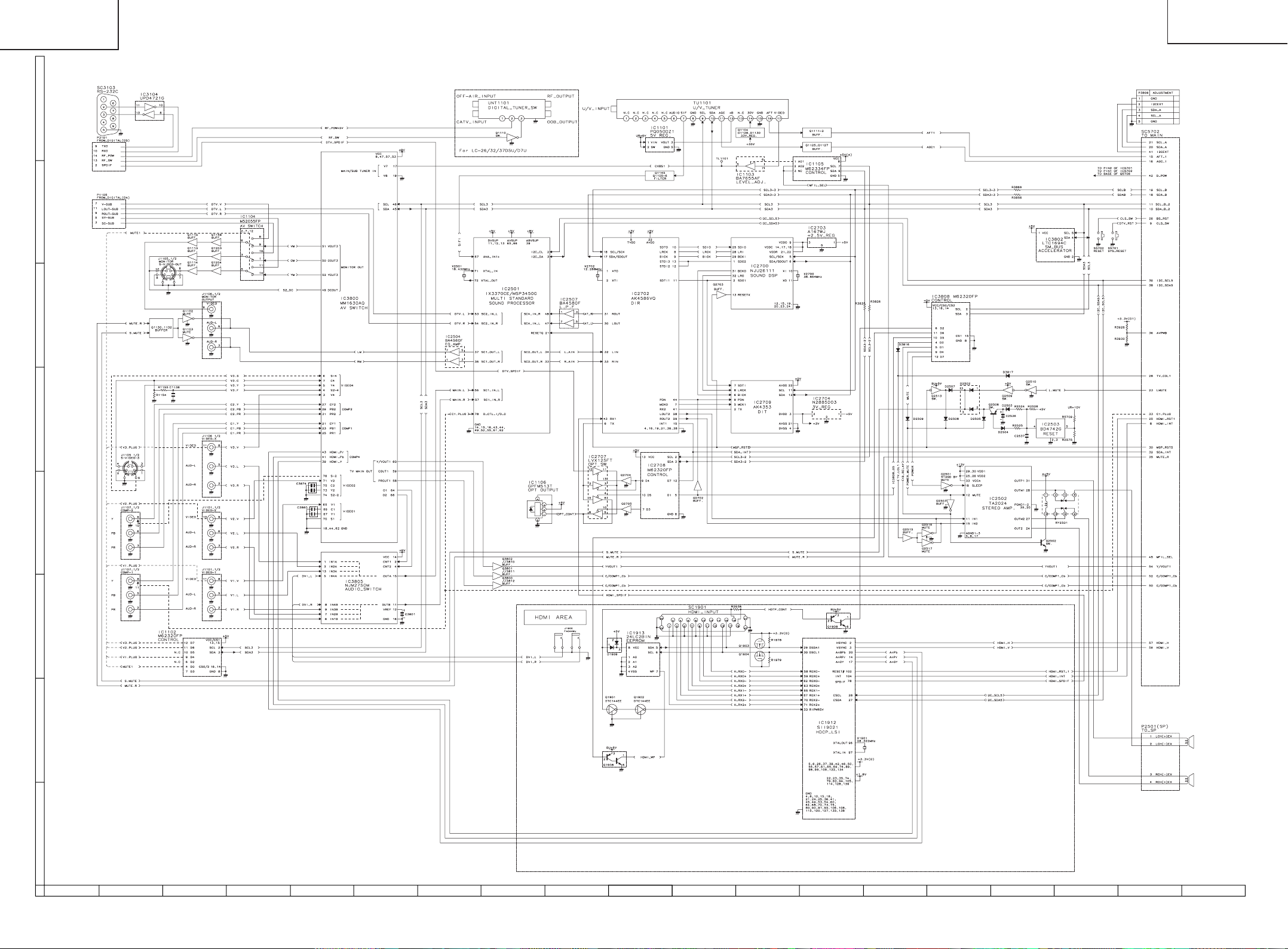
LC-26D4U
LC-32D4U
LC-37D4U
AV/AV SUB BLOCK DIAGRAM
H
G
F
LC-26D4U
LC-32D4U
LC-37D4U
E
D
C
B
A
87109654321
1716 19181514131211
6362
Page 60

LC-26D4U
LC-32D4U
LC-37D4U
PRINTED WIRING BOARD ASSEMBLIES
H
G
F
LC-26D4U
LC-32D4U
LC-37D4U
E
D
C
B
A
87109654321
DIGITAL Unit (Side-A)
1716 19181514131211
6564
Page 61

LC-26D4U
LC-32D4U
LC-37D4U
H
G
F
LC-26D4U
LC-32D4U
LC-37D4U
E
D
C
B
A
87109654321
DIGITAL Unit (Side-B)
1716 19181514131211
6766
Page 62
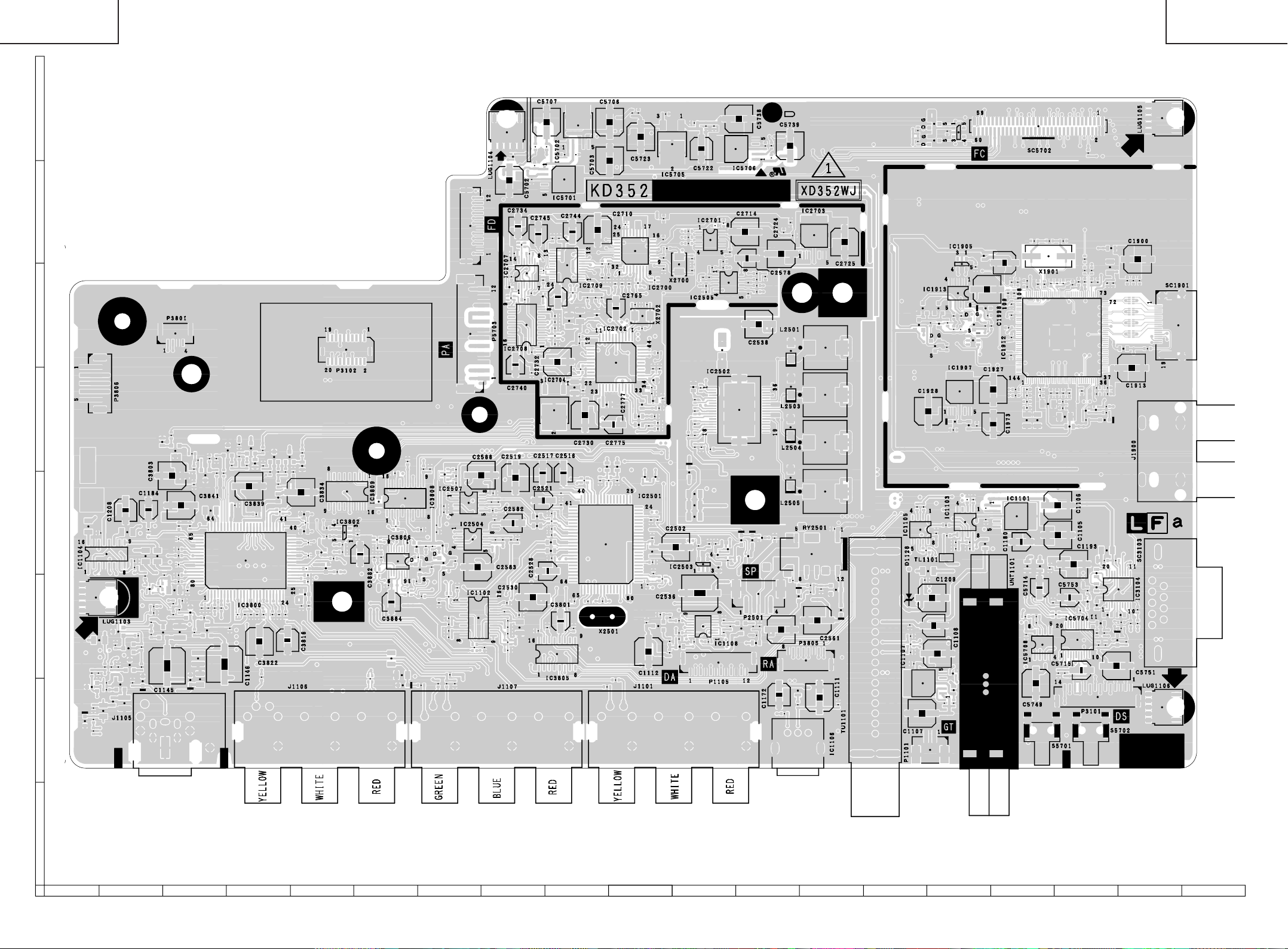
LC-26D4U
LC-32D4U
LC-37D4U
H
G
F
LC-26D4U
LC-32D4U
LC-37D4U
E
D
C
B
A
87109654321
AV Unit (Side-A)
1716 19181514131211
6968
Page 63
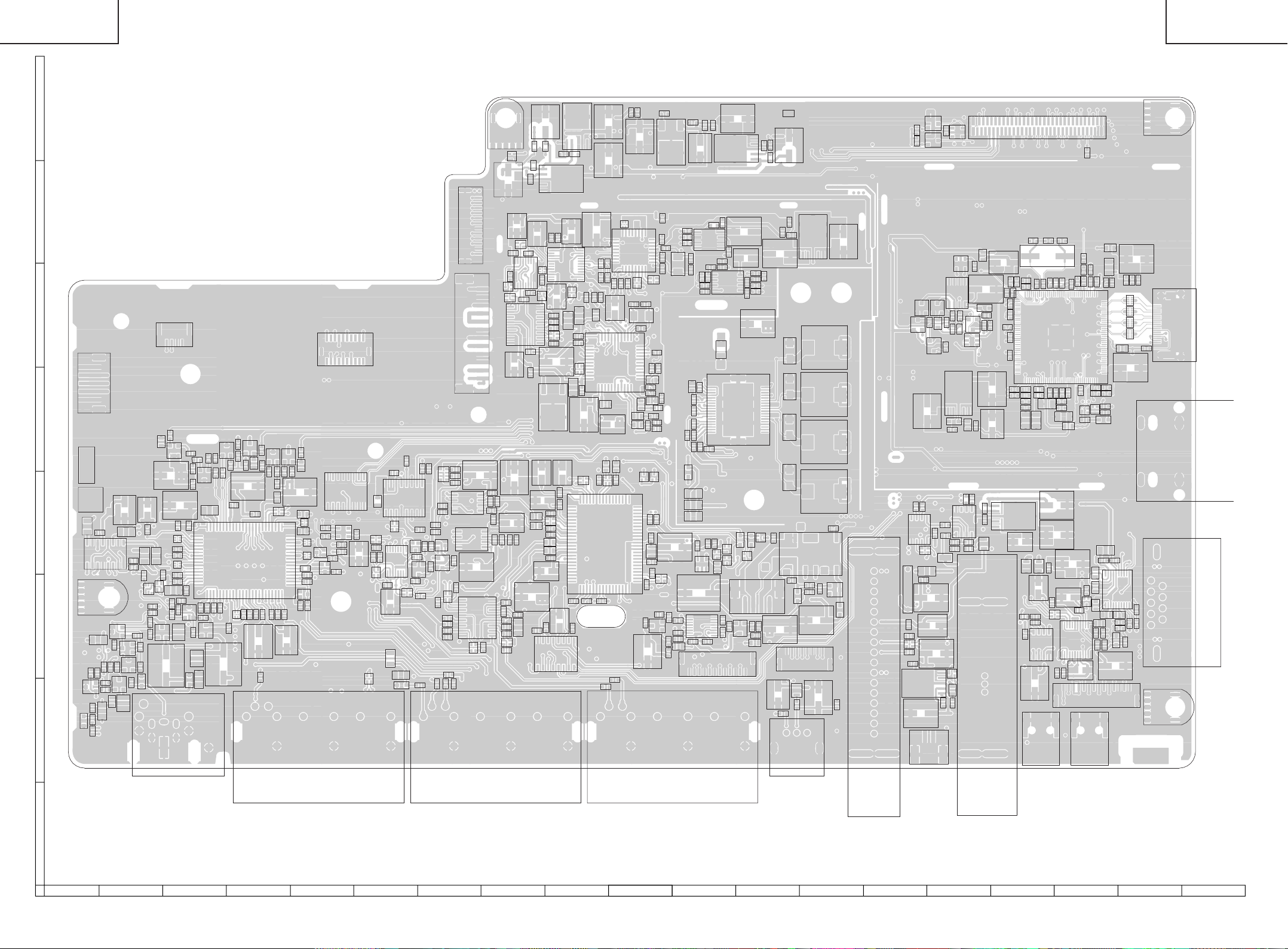
LC-26D4U
LC-32D4U
LC-37D4U
LC-26D4U
LC-32D4U
LC-37D4U
H
LUG1104
Q5706
C5702
R5722
C5701
C5704
R5709 C5707
IC5702
C5705C5708
C5703 C5706
IC5701
G
P3103
F
P3801
P3102
P3806
P5703
E
R3862
R3958
R3957
Q3810
C1122
R1182
C3803
C1200
Q1114
C1145
C3860
R3932
R3933
C3874
C3809
R3939
C1196
J1105
C3841
R1314
R1307R1316
R3941
R1306
R1245
R3956
R3922
C3810
Q1148
D1116
TEST3
TEST2
D
C1186
C
Q1203
B
D1105
C1185
LUG1103
C1192
R1290
FB3812C1142R1189
IC1104
R1317
R1311
R1289
R1242
R1188
Q1204
R1315
R1300
C1144
C1191
Q1133
R1312
Q1113
C1208
R1241
R1248
R1243
R1291
Q1134
C1134
C1190
R1184
R1299 R1288
D1110
C1183 C1184
Q1131
R1318
R1313
R1244R1292
C3836 R3863
R1308
R1246
C3811
R1247
R1157
R3955
Q3802
C3817
R3938
Q1115
R3959
R3864
R3808
R3865
R3852
C1146
Q3801
R3960
C3842
C3815
R3961C3835
C3839
IC3800
C3812
R3859
C3840
R3868
R3962
R3803 Q3811
C3876
C3822
R1156
R3860
R3963
C3897
Q3800
R3861
R3832
R3841
FB3801R3857R3964
R3842
Q3812
R3844 R3966
C3816
C3804
C3834
R3804
R3802
D3821
R3965 R3858
C3844
C3828
C3826
R3851
R3850
R3845
C3843
R3883
J1106
D3813
R3820
R3827
R3849
R3848
D3814
IC3809
IC3802
R3830
R3834
C3802
C3882
R3921
C3881
R3947
R1163
R3969
R3948
R3923
C3883
C3808
C3884
C1155
IC3808
R3810
IC3806
R3910
R1137
D1111
R3818
FB3803
R3856
R3902
Q3815
Q3806
R3866
FB3804
R3919
R3836
R3840
R3926
C3877
R3837
R3855
R3930
C3878
Q3814
C1153
R1260
R3925
Q3808
R1294
R1293
C1175
R1320
R1273
R1259
R3927
R3867
R3928
R1180
R3854
C1154
C1194
C2588
IC2507
IC2504
C2583
IC1102
R1177
C2587
R2545
C1171
R2542
C2581
R2538
J1107
Q2704
C2589
C2579
C1159
R1186
C1174
C1173
R1183
C1120
C2735
R2742
C2582
R1192
R2773
R3102
C2740
C2519
R2581
R1200
C2734
R2775
R2518
C1158
R2739
IC2707
FB2709
IC2708
R2744
C2543
C2542
C2530
C2741
R3816
C2745
C2746
C2521
C2528
C2736
Q2705
C2517
C2545
R2529
C2586
C2580
C2568
C2567
C2527
C3890
R2753
R2771
C2737
C2738
R2741
C2739
C2732
IC2704
IC3805
C2743
IC2709
C2747
C2522C2518
C3801
C2516
C2529
C2744
R2748
C2769
R2767
R2763
R3817
C2752
R2513
C2768
R2704
C2753
C2532
R2766
C2730
C2710
R2765
C2766
R2523
X2501
C2712 R2715
R2764
C2777
C2511
R1211
C2713 R2716
IC2702
C2775
C2563
R2512
IC2501
R1216
C2700
C2765
C2510 C2564
C2701
C2708
IC2700
C2702
C2762
R5735
X2702
R2710
C2778
C2784
C2728
C5723
R2705
C2761
C2782
R2706
C2773
R2728
C2781
C2776
R2756
R2769
Q2517
C2559
C2572
C1199
C1112
R2735
R2734
R2770
R2759
C2729
C2552
L2502 C2501
C2571
R1224
Q1108
C5727
R2708
C2774
Q2516
R2505
R2501
C2704
C2703R2707 FB2702
FB2704
C2502
R1223
R1227R1225
J1101
IC5705
X2700
R1175
R1251
R1226
C1188
R2787
R2788
R2789
C5721
R2532
D2520
C2509
C2569
C2570
C1132
C2705C2706
R2551
C2541
FB2503
R2514R2511
C2533C2523R2515
R2574
C2536
IC1108
C5722
IC2701
R2550
C2505
R2520
R2516
IC2503
R1249
C5724
C2709
R2549
C2520
R2575
C5726
C2555
P1105
C2524
R2560
IC2505
Q2509
C2537
R2786
FB2509
D2502Q2510
R1219
R1231
C5738
IC5706
R2713
R1218
C2714
C2578
IC2502
D2505
Q2513
Q1107
R2559
R2558
R2557
R2556
C2573C2574
C2538
D2508
P2501
R1222
C1189
Q2503
R1220
R1221
C5736
C2575
C5735R5704
C2724
C2565
C1168
C1172
R1111
TEST4
FB2700
C2726
C2566
C5739
FB2703
D2515 D2514
D2517 D2516
IC1106
R2534
R2531
D2518
P3805
FB1105 L1102
RY2501
C2561
IC2703
L2501
L2503
L2504
L2505
R2530
C1111
C2562
Q2502
D2519
C1187
C2725
TU1101
C1198
R1104
C1197
C1109
D1128
C1101
R5706R5705
D1909
R1103
R1205
C1103
IC1107
C1107
Q5754
Q5753
D1911
C1928
R1116
IC1105
C1179
C1209
C1102
P1101
R1976
C1108
D1912
FB1914
Q1903
R1204
C1166
TL1101
R1165
R1117
IC5703
C5717
R1977
R1978
D1915
C1926
C1129
R1108
Q1110
IC1913
R1972 R1974
R1118 L1103
IC1905
R1975
R1973
Q1908
IC1907
R1101
IC1103
R1107
C1181
C1965
Q1904
FB1905
C1100
C1998
D1910
C1999
C2906
FB1906
R1979
C1170R1147
L1101
UNT1101
R1969
C1927
C1973
C1974
C2943
R1998
C2917
C1970 C1969C2942
C2944
R1985
R1984
IC1101
R1907
R1999
C1180
R5743
C2912
C1966
C2934
C1968
C2936
C2935
C2946
C2933
L1104
C5747
R5742
C5748
SC5702
R1970
C2926
C2919
C2932
C5749
R1903
X1901
R1981
C2928
L1105
C5714
IC5708
S5701
C2920 C1919
C1106
C1105
C1195
C5754
R5754
C2945
IC1912
C2927 C1918
C2918
C2907
C2904
FB5706
C2921 C1971
C2925
FB1904
C1193
C5753
C5716
C2941
C5752
C5715
C2940
C2908R1967FB1921
C2937
Q1902
R1902
IC5704
R3924
C2939R1971
C2901
C2900
Q5751R5757
P3101
S5702
C2938
Q1901
D1901
C3136
C3138 C3139
C3133
C5743
R5716
R5755
FB1900
C1915
C1914
R2938
R1901
C3137
C3134
R5740
C2905
C2902
R3131
C5750
C5751
C2903
FB1901
C3135
R3106
R5714
D5706
C1913
IC3104
C1900
C1907
FL1961FL1962FL1963FL1964
R3128
R5756
C1903
R3107
R3130
LUG1105
C1905
SC1901
R1982
J1900
SC3103
LUG1106
A
87109654321
AV Unit (Side-A ChiP)
1716 19181514131211
7170
Page 64
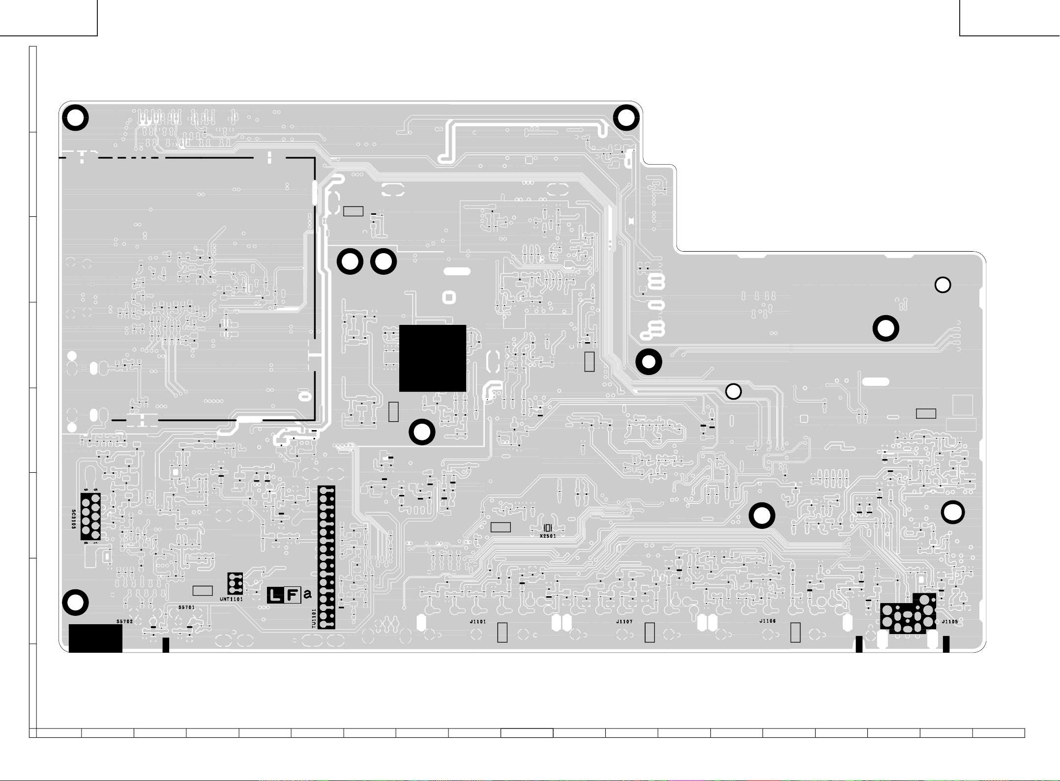
LC-26D4U
LC-32D4U
LC-37D4U
H
G
F
LC-26D4U
LC-32D4U
LC-37D4U
E
D
C
B
A
87109654321
AV Unit (Side-B)
1716 19181514131211
7372
Page 65

LC-26D4U
LC-32D4U
LC-37D4U
H
LC-26D4U
LC-32D4U
LC-37D4U
TL5714
TL5713
TL5715
TL5727
TL5716
TL5766
TL5717
TL5712
TL5726
TL5767
TL5771
TL5774
TL5779
TL5728
TL5778
TL5776
TL5730
TL5723
TL5783
TL5782
TL5786
TL5785
TL5784
TL5748
TL5788
TL5789
TL5791
TL5747
TL5790
TL5787
TL5781
TL5777
TL5772
TL5768
TL5725
G
TP1903
C2910
R1965
R2941
C2924R2951
R2926
C2923R2950
C1924C1922
R2940
C2922R2949
R2925
C2929
C1921
TP1900
R2939
R1962C1925
R1964
C2930C2931
C1923C1920
TP1902
C1916
C1917
C1904C1908
C1901C1910
C1912
C1906C1909C1911
C1902
TP1904
R1905C1930
C2909
R2927
C1929
R1904
F
TL1960
E
FB1912
TL1909
TL1907
R1959
R1960C1981
C1982R1956
TL3130
TL3132
C1978
FB1913
TL1908
R1957
FB3105
TL3134
TL3131
TL3133
C1980
R3132
FB3107
TL3101
R1958
FB3108FB3106R3133R3134
R3127FB3109
TL3106
R1961C1979
R3101
TL3107
C1983
R3135
R5712C5712
C3101
TL3108
R3105
D3104
D3105D3103
TL3109
C5713
R5713
R3104
TL3110
D3102
R5751
R5753Q5752
TL3111
TL3103
TL5798
R5752
TL3104
R3103
C5730
R5715
TL3102
FB3104
C5742R5717
TL3105
TL3112
D5702
R1310
TL3113
R5727
TL5732
R5739
R5710
R5707
R1195R1196
Q1145
R1256
R5744
C5710R5708
TL5731
C1229R1197
R1112R1304
R5745
C5729
Q1106
R1199
C1231
R5741
C5711
C1228
R5747
R5738
D5701
R1198
C1230C1227
C5746R5746
R5726
D
C
B
TL5749
TL5763
R5711
TL5792
FB1902
C1972
R1113R1106C1226
R5737
R5703
TL5752
TL5759
FB1903
R1109
R1212Q1105
R5748
TL5753
TL5758
TL5757
Q1906
Q1907R1947
R1213D1112
TL5750
TL5754
R1190
TL1123
TL5751
C1984
R1937
R1143
TL1122
TL1121
TL1120
TL1962
R1935
TL1125
R1181
TL1903
TL1902
TL1901
Q1127
C1110
D1109
C1113
R1936
Q1905
R1134
R1191
R1229
R1114
D1129
Q1111
R1906R1939
R1238R1150
Q1125
TL1961
R1240R1239
D1113R1319
R1214
C1125
TL1102
Q1104
Q1112
R1102
R1110C1182
R1202D1130
TL1119
TL1118
TL1117
TL1116
TL1115
TL1114
TL1113
TL1112
TL1111
TL1110
TL1109
TL1108
TL1107
TL1106
TL1105
TL1104
TL1103
C2560
R3060
R3057R3059
D3051R3055
R2521C2558
C2554
Q3054
R3056Q3052Q3051Q3053
C3051
TL2717
C2556C2557
C2553R2528
R3062
TL3806
TL3818
R3054R3053R3051R3869
D2700
TL2716
FB2508
C2550C2551
FB2506
TL3892
TL3807
R3812
TL1193
C2727
TL2715
FB2505
TL3808
TL3809
TL1195
FB2502
C2546
C2548
D2512
D2506
R3839R3940
TL3810
TL1194
C2539C2549
C2547
FB2507D2513
TL2502TL2503TL2504
D2501
R1228
R2519
D2507
FB2504
TL2501
TL1186
TL1184
FB3825
TL5743
Q2501
R1297
TL1187
R1230
TL1169
TL1170
R2507
D2503R2524
R1296
TL1185
C2508
Q2506
R1265
TL1188
R1235C1165
C2507R2509
C2515
R2525
D2504
TL1189
FB3824
R1274
TL1190
R1234
TL1168
R2508C2514R2510
R2526
TL1191
TL5722
C2506C2504
TL1192
R1233
FB2501
R2533
R1250
FB3823
TL1167
R1262
R1257
R2751
R2536
C1164
Q2703
R2752
R1232
C2711
R2585
C1163
R2709
R2738
C2772
R2760
R2772
R2502
R2555
FB3822
TL1166
C2771
R2506
R2586
R2552
R1236C1162
C2780
C2722
Q2515
R2554
TL5724
Q2702
C2503
FB3817D1118
R2702
R2703
C2783
C2707R2761R2757
R2584
C2540
TL1165
R2701
R2711
C2764
R2758C2779
R2583
R2553
C2535
R1215
TL1164
TL1124
R2712
R2700
R2749
C2763
R2762
D2509
C1149
C2754
C2749
R2783
C2751
TL1163
C2750
R2782
C2720
D1117
TL1162
R2784
FB3816C1148
R2747R2750
C2748
R2785
C2531
C2534
TL5718
C2767
TL2712
R1208
TL5721
C2770
C2526
FB3809
R2746
C2731
C2513
C2544
TL1148
TL1146
R5702
C2742FB2701
TL2711
D2702
C2584
C2525
R1139
TL5720
R2745
R2740
C2733
R5701
C2512
FB3808C1157
R5723
TL5719
C2585
R1255
TL1147
Q5707
C1161
FB3807
R2546
R2503
TL1144
TL1145
R5774
R2547
R2535
R1138C1156
R5720
C5709
R2541
R2572R2580
TL5741
R5721
R2548
R2522
R1253
TL5742
TL5740
TL5733
TL5703
TL5708
TL5710
TL5706
TL5711
TL5709
TL5707
TL5704
TL5702
TL5705
TL5701
R2544
R2504
R2573
FB3806C1160
TL1143
R2540
R2543
R2537
R3108
C2577
R2527
FB3805R1136
C2595
TL1139
TL1142
R2582
TL1140
R2539
R2517
D1107C1152
R1105
C1151
TL1138
TL1141
C1133R1173
D3816
R1209C1147
D3817
R3950
R1170
Q1130
R3828
R3949
R1167
R1210
C1123
FB3821
TL1180
TL1181
R3835R3829
R1166Q1103
R1146
TL5729
R3826
R1159
Q1132
FB3820
TL5736
TL5735
Q1102
R1160
TL1179
C3866
R1148
TL5737
TL5739
TL5738
R1145
R1149
C1141
TL5734
C1143R1115
R1161
FB3819
TL1177
TL1178
C1150
R1162
R3809
R3847
D3815
R3882
FB3818R1151C1135
TL1176
R1152
D3820
R3881
FB3815D1108
R3942
R3872
C3857
C3807
D3822
R1194R1193
TL1174
TL1175
R3831
R3833
R3843
R3822
R3935
C3821
C3805
FB3814
TL1173
R3934
TL1172
R1158
R3871
D3805
D1120C1140
R3870
D3804
D1106
TL1158
R3806
FB3813R1185R1258
TL1155
TL1156
D3806
R3807
D3801
TL3802
D3807
R3853R3805
TL1159
TL1171
TL3800
TL3801
C1213
R3801
R3815
C1139
R1280
R1254
TL1150
TL1157
R1279
R1172R1174
C1138
TL1149
TL1154
R1171
Q1126
R1287
R1155
Q1129
R1169
Q1120
C1136R1154
Q1128R1270
C1137
TL1152
TL1151
TL1153
R1176
Q1122
R1187
R1179
Q1109
D1121R1153
R1286R1272
R1266
TL3820
TL3821
TL3822
TL3823
TL3824
R1207
C1121
R1268
Q1124
TEST5
TEST6
R1206
R1295
C1131
R1267
Q1123
R1178
R1269
A
87109654321
AV Unit (Side-B ChiP)
1716 19181514131211
7574
Page 66

LC-26D4U
Q151
D155
R154
1
S157
P151
P152
S153
S151
S152
R152
6
D151
2
R151 D152 R153
S154
S155
TL157
TL155
TL156
TL151
3
TL153
4
TL161
TL152
TL154
TL159
TL160
TL162
TL163
LC-32D4U
LC-37D4U
H
G
F
KEY Unit (Side-A)
KEY Unit (Side-A Chip)
E
D
KEY Unit (Side-B)
C
B
A
KEY Unit (Side-B Chip)
76
654321
Page 67

LC-26D4U
LC-32D4U
LC-37D4U
H
R/C, LED Unit (Side-A)
G
F
R/C, LED Unit (Side-A Chip)
E
D
R/C, LED Unit (Side-B)
C
R101
TL102
TL104
TL106
TL101
TL103
TL105
B
TL2420
D101
C102
R106
R117
Q105
Q104
A
R/C, LED Unit (Side-B Chip)
654321
77
Page 68

LC-26D4U
LC-32D4U
LC-37D4U
H
G
F
LC-26D4U
LC-32D4U
LC-37D4U
E
D
C
B
A
87109654321
MAIN Unit (Side-A)
1716 19181514131211
7978
Page 69

LC-26D4U
LC-32D4U
LC-37D4U
H
G
F
LC-26D4U
LC-32D4U
LC-37D4U
E
D
C
B
A
87109654321
MAIN Unit (Side-B)
1716 19181514131211
8180
Page 70

LC-26D4U
LC-32D4U
LC-37D4U
H
G
F
LC-26D4U
LC-32D4U
LC-37D4U
E
D
C
B
A
POWER SUPPLY Unit (Side-A)
(LC-26D4U)
87109654321
1716 19181514131211
8382
Page 71

LC-26D4U
LC-32D4U
LC-37D4U
H
G
F
LC-26D4U
LC-32D4U
LC-37D4U
E
D
C
B
A
POWER SUPPLY Unit (Side- B)
(LC-26D4U)
87109654321
1716 19181514131211
8584
Page 72

LC-26D4U
LC-32D4U
LC-37D4U
H
G
F
LC-26D4U
LC-32D4U
LC-37D4U
E
D
C
B
A
POWER SUPPLY Unit (Side- B ChiP)
(LC-26D4U)
87109654321
1716 19181514131211
8786
Page 73

LC-26D4U
LC-32D4U
LC-37D4U
H
G
F
LC-26D4U
LC-32D4U
LC-37D4U
E
D
C
B
A
POWER SUPPLY Unit (Side-A)
(LC-32D4U)
87109654321
1716 19181514131211
8988
Page 74
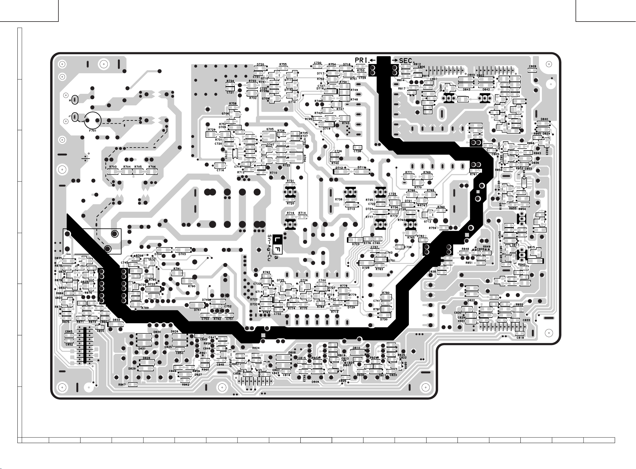
LC-26D4U
LC-32D4U
LC-37D4U
H
G
F
LC-26D4U
LC-32D4U
LC-37D4U
E
D
C
B
A
POWER SUPPLY Unit (Side-B)
(LC-32D4U)
87109654321
1716 19181514131211
9190
Page 75
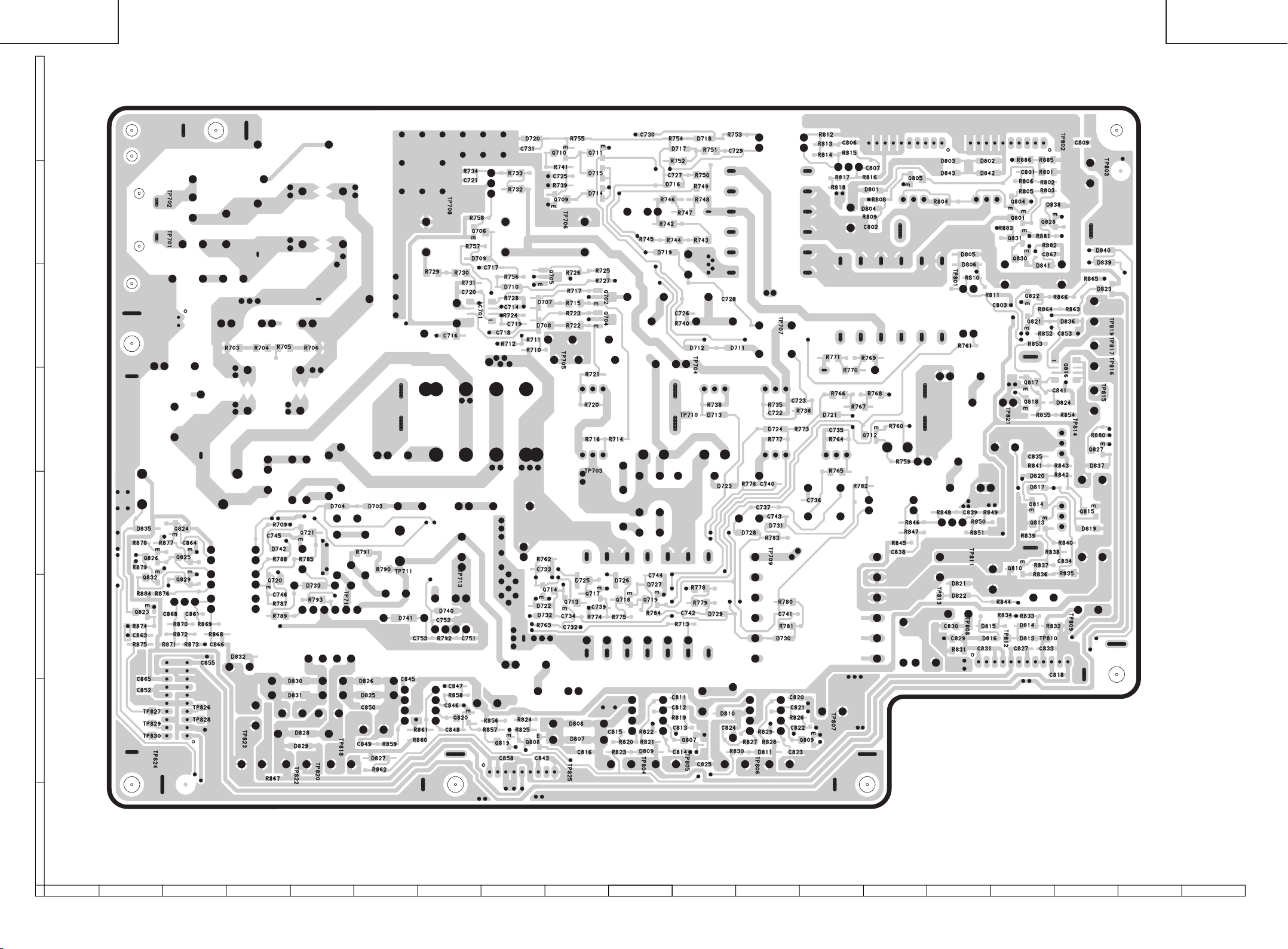
LC-26D4U
LC-32D4U
LC-37D4U
H
G
F
LC-26D4U
LC-32D4U
LC-37D4U
E
D
C
B
A
POWER SUPPLY Unit (Side-B ChiP)
(LC-32D4U)
87109654321
1716 19181514131211
9392
Page 76

LC-26D4U
LC-32D4U
LC-37D4U
H
G
F
LC-26D4U
LC-32D4U
LC-37D4U
E
D
C
B
A
POWER SUPPLY Unit (Side-A)
(LC-37D4U)
87109654321
1716 19181514131211
9594
Page 77
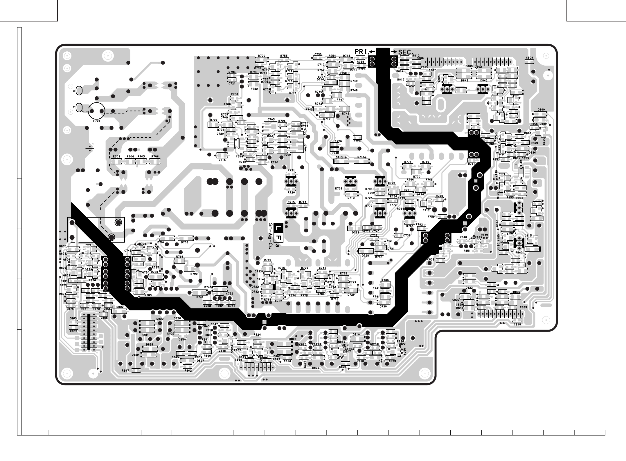
LC-26D4U
LC-32D4U
LC-37D4U
H
G
F
LC-26D4U
LC-32D4U
LC-37D4U
E
D
C
B
A
POWER SUPPLY Unit (Side-B)
(LC-37D4U)
87109654321
1716 19181514131211
9796
Page 78

LC-26D4U
LC-32D4U
LC-37D4U
H
G
F
LC-26D4U
LC-32D4U
LC-37D4U
E
D
C
B
A
POWER SUPPLY Unit (Side-B ChiP)
(LC-37D4U)
87109654321
1716 19181514131211
9998
Page 79

LC-26D4U
LC-32D4U
LC-37D4U
PARTS LIST
PARTS REPLACEMENT
Replacement parts which have these special safety characteristics
identified in this manual; electrical components having such features
are identified by å and shaded areas in the Replacement Parts
Lists and Schematic Diagrams. The use of a substitute replacement
part which dose no have the same safety characteristic as the factory recommended replacement parts shown in this service manual
may create shock, fire or other hazards.
"HOW TO ORDER REPLACEMENT PARTS"
To have your order filled promptly and correctly, please furnish the
following informations.
1. MODEL NUMBER 2. REF. NO.
3. PART NO. 4. DESCRIPTION
in USA: Contact your nearest SHARP Parts Distributor to order.
Ref. No. Part No. ★ Description Code Ref. No. Part No. ★ Description Code
PRINTED WIRING BOARD ASSEMBLIES
NOTE: THE PARTS HERE SHOWN ARE SUPPLIED AS AN
For location of SHARP Parts Distributor, Please call TollFree; 1-800-BE-SHARP
(NOT REPLACEMENT ITEM)
DUNTKD331FE12 – DIGITAL Unit —
DUNTKD352DE17 – AV Unit —
DUNTKD353DE17 – KEY Unit —
DUNTKD354DE17 – R/C, LED Unit —
DUNTKD376FE04 – MAIN Unit —
RDENCA138WJQZ – POWER Unit —
DUNTKD331FE13 – DIGITAL Unit —
DUNTKD352DE18 – AV Unit —
DUNTKD353DE18 – KEY Unit —
DUNTKD354DE18 – R/C, LED Unit —
DUNTKD376FE05 – MAIN Unit —
RDENCA139WJQZ – POWER Unit —
DUNTKD331FE14 – DIGITAL Unit —
DUNTKD352DE19 – AV Unit —
DUNTKD353DE19 – KEY Unit —
DUNTKD354DE19 – R/C, LED Unit —
DUNTKD376FE06 – MAIN Unit —
RDENCA140WJQZ – POWER Unit —
(LC-26D4U)
(LC-32D4U)
(LC-37D4U)
LCD PANEL
ASSEMBLY BUT NOT INDEPENDENTLY.
RLCUCA024WJZZ J
RLCUCA025WJZZ J
RLCUCA026WJZZ J
26 WIDE LCD PANEL MODULE Unit
32 WIDE LCD PANEL MODULE Unit
37 WIDE LCD PANEL MODULE Unit
ERSATZTEILLISTE
AUSTAUSCH VON TEILEN
Les pi`eces de rechange qui pr élelesentent ces caract éleristiques
sp éleciales de s élecurit éle, sont identifi élees dans ce manuel :
lespi`eces élelectriques qui pr élesentent ces particularit éles, sont
rep éler élee par la marque ået sont hachur élees dans les listes de
pi`eces et dans les diagrammes sch élematiques.
La substitution d'une pi`ece de rechange par une autre qui ne pr
éLesente pas les m éoemes caract éLeristiques de s élecurit éle
que la pi`ece recommand élee parl'usine et dans ce manuel de service, peut provoquer une éLelectrocution, un incendie ou toutautre
sinistre.
"COMMENT COMMANDER LES PIECES DE RECHANGE"
Pour que votre commande soit rapidement et correctement remplie,
veuillez fournir les renseignements suivants.
1. NUMERO DU MODELE 2. NO. DE REF
3. NO. DE PIECE 4. DESCRIPTION
in CANADA: Contact SHARP Electronics of Canada Limited
Phone (416) 890-2100
★ MARKIERUNG : ERSATZTEILE-LIEFERUNG★ MARK: SPARE PARTS-DELIVERY SECTION
DUNTKD331FE12/13/14 (LC-26/32/37D4U)
DIGITAL Unit
TUNER
NOTE: THE PARTS HERE SHOWN ARE SUPPLIED AS AN
ASSEMBLY BUT NOT INDEPENDENTLY.
TU8001 RTUDTA018WJZZ J Tuner
INTEGRATED CIRCUITS
IC8051 VHiPC2798GR-1Y J UPC2798GR-E1 AM
IC8052 VHiPC2708TB-1Y J UPC2708TB-E3 AF
IC8101 RH-iXB145WJQZQ J MN2WS0025AG-A BM
IC8102 VHiPQ1X331M-1Y J PQ1X331M2ZP AD
IC8301 RH-iXB038WJQZQ J EDD2516AKTA-6B AZ
IC8302 RH-iXB038WJQZQ J EDD2516AKTA-6B AZ
IC8304 VHiBD3533F+-1Y J BD3533F-E2 AG
IC8401 RH-iXB422WJQZY J MK3732-26GLFTR AL
IC8451 VHiLHF12FT5-1Q J LH28F128BFHED- BC
IC8453 VHiBR24L64F-1Y J BR24L64F-WE2 AK
IC8601 RH-iXB087WJZZQ J 218T313ZZA01G BG
IC8602 VHiPQ1X181M-1Y J PQ1X181M2ZPH AD
IC8603 VHiPQ1X181M-1Y J PQ1X181M2ZPH AD
IC8701 VHiPQ1X331M-1Y J PQ1X331M2ZP AD
IC8801 VHiAK4363VF-1Y J AK4363VF AQ
IC8802 VHiNJM4565V-1Y J NJM4565V AF
IC8803 VHiNJM4565V-1Y J NJM4565V AF
IC8902 VHiMM1566AJ-1Y J MM1566AJBE AG
IC9002 VHiTC7W66U/-1Y J TC7W66FU AE
IC9005 VHiMLC157DT-1Y J MC74LCX157DTR2 AE
IC9006 VHi7WH126FU-1Y J TC7WH126FU AE
IC9007 VHiPQ1X331M-1Y J PQ1X331M2ZP AD
IC9101 RH-iXB500WJQ1Q J I.C.
IC9201 RH-iXB011WJZZY J SN74ALVCH16282 AM
IC9306 VHiLV541AT+-1Y J SN74LV541APWR AG
IC9307 VHiLV541AT+-1Y J SN74LV541APWR AG
IC9308 VHiLV541AT+-1Y J SN74LV541APWR AG
IC9309 VHiLV541AT+-1Y J SN74LV541APWR AG
IC9310 RH-iXB007WJZZY J SN74CBTLV16210 AM
IC9402 VHiTPS2022D-1Y J TPS2022DR AQ
IC9403 RH-iXB016WJZZY J LTC1470CS8#TRP AU
IC9405 VHiLVC1G07C-1Y J SN74LVC1G07 AE
IC9501 VHiBD5227G+-1Y J BD5227G-TR AD
IC9502 RH-iXB474WJQ1Q J I.C.
IC9503 RH-iXB475WJQ1Q J I.C.
IC9601 VHiPQ1CZ41H-1Y J PQ1CZ41H2ZP AG
IC9602 VHiPQ1CZ41H-1Y J PQ1CZ41H2ZP AG
100
Page 80

LC-26D4U
LC-32D4U
LC-37D4U
Ref. No. Part No. ★ Description Code Ref. No. Part No. ★ Description Code
DUNTKD331FE12/13/14 (LC-26/32/37D4U)
DIGITAL Unit (Continued)
IC9603 VHiTPS54350-1Y J TPS54350PWPR AN
IC9604 VHiPQ1CX12H-1Y J PQ1CX12H2ZP AK
IC9605 VHiPQ090DNA-1Y J PQ090DNA1ZPH AE
IC9606 VHiMP1571DS-1Y J MP1571DS-LF-Z
IC9608 VHiPQ1M335M-1Y J PQ1M335M2SP AD
IC9701 VHiPQ1CX12H-1Y J PQ1CX12H2ZP AK
IC9702 VHiPQ1CZ41H-1Y J PQ1CZ41H2ZP AG
TRANSISTORS
Q8451 VSRT1N141U/-1Y J RT1N141U AB
Q8452 VS2SA1362GR-1Y J 2SA1362GR AC
Q8801 VSRT1N141U/-1Y J RT1N141U AB
Q8802 VSRT1P441U/-1Y J RT1P441U AB
Q8803 VSDTC314TK/-1Y J DTC314TK AC
Q8804 VSDTC314TK/-1Y J DTC314TK AC
Q8901 VSDTC144EE/-1Y J DTC144EE AA
Q8903 VSRN1903///-1Y J RN1903 AB
Q9001 VS2SA1989R/-1Y J 2SA1989R AB
Q9601 VSRTQ045N03-1Y J RTQ045N03 AE
Q9602 VSDTC144EE/-1Y J DTC144EE AA
Q9603 VSRTR020P02-1Y J RTR020P02 AD
Q9604 VS2SC5383F/-1Y J 2SC5383F AB
Q9605 VS2SC5383F/-1Y J 2SC5383F AB
DIODES
D8101 RH-PXA018WJZZY J GM1HD55200A AC
D8102 RH-PXA018WJZZY J GM1HD55200A AC
D8451 VHD1SS355//-1Y J 1SS355 AB
D9601 VHDDG1M3+++-1Y J DG1M3 AC
D9602 VHDDG1M3+++-1Y J DG1M3 AC
D9603 VHD1SS355//-1Y J 1SS355 AB
D9604 VHDLi124+++-1Y J Li124 AC
D9605 VHDDG1M3+++-1Y J DG1M3 AC
D9606 VHDDAN222//-1Y J DAN222 AA
D9607 RH-EX1395CEZZY J Zener Diode, 6.2V AC
D9701 VHDLi124+++-1Y J Li124 AC
D9702 VHDDG1M3+++-1Y J DG1M3 AC
D9703 VHDLi124+++-1Y J Li124 AC
PACKAGED CIRCUITS
X8401 RCRSCA086WJZZY J Crystal AG
X8601 RCRSCA094WJZZY J Crystal AG
COILS AND FILTERS
FL8051 RFiLZA019WJZZ J Filter AG
FL8105 RFiLNA044WJZZY J Filter AC
FL8402 RFiLNA043WJZZY J Filter
FL9201 RFiLNA043WJZZY J Filter
L8051 VPBXMR15KR30UY J Peaking, 0.15µHAB
L8052 VPBXMR15KR30UY J Peaking, 0.15µHAB
L8053 VPBXM82NMR17UY J Peaking AB
L8054 VPBXMR10KR22UY J Peaking, 0.1µHAB
L8055 VPBXMR15KR30UY J Peaking, 0.15µHAB
L8056 VPBXM82NMR17UY J Peaking AB
L8057 VP-9N82NMR11NY J Peaking AB
L8058 VP-9N82NMR11NY J Peaking AB
L8059 VP-9N82NMR11NY J Peaking AB
L8060 VP-9N1R8KR31NY J Peaking, 1.8µHAB
L8061 VP-9NR82KR56NY J Peaking, 0.82µHAB
L8101 VPCEM100MR70NY J Peaking, 10µHAC
L8102 VPCEM100MR70NY J Peaking, 10µHAC
L8801 VPCEM220M1R7NY J Peaking, 22µHAC
L9601 RCiLCA035WJZZY J Coil AD
L9602 RCiLPA158WJZZY J Coil AE
L9603 RCiLPA156WJZZY J Coil AE
L9604 RCiLCA031WJZZY J Coil AD
L9605 RCiLPA194WJZZY J Coil
L9702 RCiLCA035WJZZY J Coil AD
L9703 RCiLCA035WJZZY J Coil AD
CAPACITORS
C8001 RC-KZA067WJZZY J 4.7 10V Ceramic AB
C8002 VCKYCZ1AB104KY J 0.1 10V Ceramic AB
C8003 VCKYCZ1AB104KY J 0.1 10V Ceramic AB
C8051 VCCCCY1HH560JY J 56p 50V Ceramic AB
C8052 VCCCCY1HH180JY J 18p 50V Ceramic AA
C8053 VCCCCY1HH270JY J 27p 50V Ceramic AA
C8054 VCCCCY1HH151JY J 150p 50V Ceramic AA
C8055 VCCCCY1HH820JY J 82p 50V Ceramic AA
C8056 VCCCCY1HH390JY J 39p 50V Ceramic AA
C8057 VCCCCY1HH270JY J 27p 50V Ceramic AA
C8058 VCCCCY1HH330JY J 33p 50V Ceramic AA
C8059 VCCCCY1HH151JY J 150p 50V Ceramic AA
C8060 VCCCCY1HH390JY J 39p 50V Ceramic AA
C8061 VCCCCY1HH220JY J 22p 50V Ceramic AA
C8062 VCCCCY1HH101JY J 100p 50V Ceramic AA
C8063 VCKYCY1HB102KY J 1000p 50V Ceramic AA
C8064 VCCCCY1HH7R0DY J 7p 50V Ceramic AA
C8065 VCCCCY1HH3R0CY J 3p 50V Ceramic AA
C8066 VCCCCY1HH300JY J 30p 50V Ceramic AA
C8067 VCKYCY1HB102KY J 1000p 50V Ceramic AA
C8068 VCKYCY1HB103KY J 0.01 50V Ceramic AA
C8069 VCCCCY1HH101JY J 100p 50V Ceramic AA
C8070 VCKYCY1CB104KY J 0.1 16V Ceramic AB
C8071 VCCCCY1HH101JY J 100p 50V Ceramic AA
C8072 VCCCCY1HH8R0DY J 8p 50V Ceramic AA
C8073 VCCCCY1HH300JY J 30p 50V Ceramic AA
C8074 VCCCCY1HH6R0DY J 6p 50V Ceramic AA
C8075 VCCCCY1HH100DY J 10p 50V Ceramic AA
C8076 VCKYCY1CB104KY J 0.1 16V Ceramic AB
C8077 RC-KZ0124TAZZY J 10 6.3V AC
C8078 VCKYCY1HB103KY J 0.01 50V Ceramic AA
C8079 VCKYCY1HB103KY J 0.01 50V Ceramic AA
C8080 VCKYCY1CB104KY J 0.1 16V Ceramic AB
C8081 VCKYCY1HB103KY J 0.01 50V Ceramic AA
C8082 VCKYCY1HB103KY J 0.01 50V Ceramic AA
C8083 VCKYCY1HB103KY J 0.01 50V Ceramic AA
C8084 VCKYCY1HB102KY J 1000p 50V Ceramic AA
C8085 VCKYCY1CB104KY J 0.1 16V Ceramic AB
C8086 VCCCCY1HH101JY J 100p 50V Ceramic AA
C8087 VCKYCY1HB103KY J 0.01 50V Ceramic AA
C8088 RC-KZA067WJZZY J 4.7 10V Ceramic AB
C8101 VCKYCZ1CF104ZY J 0.1 16V Ceramic AA
C8102 RC-KZA176WJZZY J 10 10V Ceramic AC
C8103 RC-KZA176WJZZY J 10 10V Ceramic AC
C8104 VCKYCZ1CF104ZY J 0.1 16V Ceramic AA
C8105 VCKYCZ1CF104ZY J 0.1 16V Ceramic AA
C8106 RC-KZA176WJZZY J 10 10V Ceramic AC
C8107 VCKYCZ1CF104ZY J 0.1 16V Ceramic AA
C8108 VCKYCZ1CF104ZY J 0.1 16V Ceramic AA
C8109 VCKYCZ1CF104ZY J 0.1 16V Ceramic AA
C8110 VCKYCY1AB105KY J 1 10V Ceramic AB
C8111 VCKYCY1AB105KY J 1 10V Ceramic AB
C8112 VCKYCZ1CF104ZY J 0.1 16V Ceramic AA
C8113 RC-KZA176WJZZY J 10 10V Ceramic AC
C8114 VCKYCZ1CF104ZY J 0.1 16V Ceramic AA
C8115 VCKYCZ1CF104ZY J 0.1 16V Ceramic AA
C8116 VCKYCY1AB105KY J 1 10V Ceramic AB
C8117 VCKYCY1AB105KY J 1 10V Ceramic AB
C8118 VCKYCZ1CF104ZY J 0.1 16V Ceramic AA
C8119 RC-KZA176WJZZY J 10 10V Ceramic AC
C8120 RC-KZA176WJZZY J 10 10V Ceramic AC
C8121 VCKYCZ1CF104ZY J 0.1 16V Ceramic AA
C8122 VCKYCY1AB105KY J 1 10V Ceramic AB
C8123 VCKYCZ1AB104KY J 0.1 10V Ceramic AB
C8124 VCKYCZ1CF104ZY J 0.1 16V Ceramic AA
C8126 RC-KZA067WJZZY J 4.7 10V Ceramic AB
C8133 VCKYCZ1CF104ZY J 0.1 16V Ceramic AA
C8134 VCKYCZ1CF104ZY J 0.1 16V Ceramic AA
C8135 VCKYCZ1CF104ZY J 0.1 16V Ceramic AA
C8136 VCKYCZ1CF104ZY J 0.1 16V Ceramic AA
C8137 VCKYCZ1CF104ZY J 0.1 16V Ceramic AA
C8138 VCKYCZ1CF104ZY J 0.1 16V Ceramic AA
C8139 VCKYCZ1CF104ZY J 0.1 16V Ceramic AA
C8140 VCKYCZ1EB103KY J 0.01 25V Ceramic AA
C8301 VCEASY0JN227MY J 220 6.3V Electrolytic AC
C8302 VCKYCZ1CF104ZY J 0.1 16V Ceramic AA
C8303 VCKYCZ1CF104ZY J 0.1 16V Ceramic AA
101
Page 81

LC-26D4U
LC-32D4U
LC-37D4U
Ref. No. Part No. ★ Description Code Ref. No. Part No. ★ Description Code
DUNTKD331FE12/13/14 (LC-26/32/37D4U)
DIGITAL Unit (Continued)
C8304 VCKYCZ1CF104ZY J 0.1 16V Ceramic AA
C8305 VCKYCZ1CF104ZY J 0.1 16V Ceramic AA
C8306 VCKYCZ1CF104ZY J 0.1 16V Ceramic AA
C8307 VCKYCZ1CF104ZY J 0.1 16V Ceramic AA
C8308 VCKYCZ1CF104ZY J 0.1 16V Ceramic AA
C8309 VCKYCZ1CF104ZY J 0.1 16V Ceramic AA
C8310 RC-KZA176WJZZY J 10 10V Ceramic AC
C8311 VCKYCZ1CF104ZY J 0.1 16V Ceramic AA
C8312 VCKYCZ1CF104ZY J 0.1 16V Ceramic AA
C8313 VCKYCZ1CF104ZY J 0.1 16V Ceramic AA
C8314 VCKYCZ1CF104ZY J 0.1 16V Ceramic AA
C8315 VCKYCZ1CF104ZY J 0.1 16V Ceramic AA
C8316 VCKYCZ1CF104ZY J 0.1 16V Ceramic AA
C8317 VCKYCZ1CF104ZY J 0.1 16V Ceramic AA
C8318 VCKYCZ1CF104ZY J 0.1 16V Ceramic AA
C8319 VCKYCZ1CF104ZY J 0.1 16V Ceramic AA
C8320 VCKYCZ1CF104ZY J 0.1 16V Ceramic AA
C8321 VCKYCZ1CF104ZY J 0.1 16V Ceramic AA
C8322 VCKYCZ1CF104ZY J 0.1 16V Ceramic AA
C8323 VCKYCZ1CF104ZY J 0.1 16V Ceramic AA
C8324 VCKYCZ1CF104ZY J 0.1 16V Ceramic AA
C8325 RC-KZA176WJZZY J 10 10V Ceramic AC
C8326 RC-KZA176WJZZY J 10 10V Ceramic AC
C8327 RC-KZA176WJZZY J 10 10V Ceramic AC
C8328 VCKYCZ1CF104ZY J 0.1 16V Ceramic AA
C8329 VCKYCZ1CF104ZY J 0.1 16V Ceramic AA
C8330 VCKYCZ1CF104ZY J 0.1 16V Ceramic AA
C8331 VCKYCZ1CF104ZY J 0.1 16V Ceramic AA
C8332 VCKYCZ1CF104ZY J 0.1 16V Ceramic AA
C8333 VCKYCZ1CF104ZY J 0.1 16V Ceramic AA
C8334 VCKYCZ1CF104ZY J 0.1 16V Ceramic AA
C8335 VCKYCZ1CF104ZY J 0.1 16V Ceramic AA
C8336 VCKYCZ1CF104ZY J 0.1 16V Ceramic AA
C8337 VCKYCZ1CF104ZY J 0.1 16V Ceramic AA
C8338 VCKYCZ1CF104ZY J 0.1 16V Ceramic AA
C8339 VCKYCZ1CF104ZY J 0.1 16V Ceramic AA
C8340 VCKYCZ1CF104ZY J 0.1 16V Ceramic AA
C8341 VCKYCZ1CF104ZY J 0.1 16V Ceramic AA
C8342 VCKYCZ1CF104ZY J 0.1 16V Ceramic AA
C8343 VCKYCZ1CF104ZY J 0.1 16V Ceramic AA
C8344 RC-KZA176WJZZY J 10 10V Ceramic AC
C8345 RC-KZA067WJZZY J 4.7 10V Ceramic AB
C8346 VCKYCZ1CF104ZY J 0.1 16V Ceramic AA
C8347 VCKYCZ1CF104ZY J 0.1 16V Ceramic AA
C8348 VCKYCZ1CF104ZY J 0.1 16V Ceramic AA
C8349 VCKYCZ1CF104ZY J 0.1 16V Ceramic AA
C8350 VCKYCZ1CF104ZY J 0.1 16V Ceramic AA
C8351 VCKYCZ1CF104ZY J 0.1 16V Ceramic AA
C8352 VCKYCZ1CF104ZY J 0.1 16V Ceramic AA
C8353 VCKYCZ0JF105ZY J 1 6.3V Ceramic AA
C8354 VCKYCZ0JF105ZY J 1 6.3V Ceramic AA
C8355 VCKYCZ0JF105ZY J 1 6.3V Ceramic AA
C8401 RC-KZ0083TAZZY J 2.2 10V AC
C8402 VCCCCZ1HH4R0CY J 4p 50V Ceramic AA
C8403 VCCCCZ1HH3R0CY J 3p 50V Ceramic AA
C8404 VCKYCZ1CF104ZY J 0.1 16V Ceramic AA
C8405 VCKYCZ1CF104ZY J 0.1 16V Ceramic AA
C8406 VCKYCZ1CF104ZY J 0.1 16V Ceramic AA
C8451 VCKYCZ1CF104ZY J 0.1 16V Ceramic AA
C8452 VCKYCZ1CF104ZY J 0.1 16V Ceramic AA
C8453 VCKYCZ1CF104ZY J 0.1 16V Ceramic AA
C8455 VCKYCZ1CF104ZY J 0.1 16V Ceramic AA
C8601 VCKYCZ1AB104KY J 0.1 10V Ceramic AB
C8602 VCKYCZ1AB104KY J 0.1 10V Ceramic AB
C8604 VCKYCZ1AB104KY J 0.1 10V Ceramic AB
C8605 VCKYCY1CF105ZY J 1 16V Ceramic AA
C8606 VCKYCZ1HB102KY J 1000p 50V Ceramic AB
C8607 VCKYCZ1CF104ZY J 0.1 16V Ceramic AA
C8608 VCKYCZ1CF104ZY J 0.1 16V Ceramic AA
C8609 VCKYCZ1CF104ZY J 0.1 16V Ceramic AA
C8610 VCKYCZ1CF104ZY J 0.1 16V Ceramic AA
C8612 VCKYCZ1CF104ZY J 0.1 16V Ceramic AA
C8613 VCKYCZ1CF104ZY J 0.1 16V Ceramic AA
C8614 VCKYCZ1CF104ZY J 0.1 16V Ceramic AA
C8616 VCKYCZ1AB104KY J 0.1 10V Ceramic AB
C8617 VCKYCZ1AB104KY J 0.1 10V Ceramic AB
C8618 VCKYCZ1AB104KY J 0.1 10V Ceramic AB
C8619 VCKYCZ1CF104ZY J 0.1 16V Ceramic AA
C8620 VCKYCZ1AB104KY J 0.1 10V Ceramic AB
C8621 VCKYCZ1EB103KY J 0.01 25V Ceramic AA
C8622 VCKYCZ1HB102KY J 1000p 50V Ceramic AB
C8623 VCKYCZ1AB104KY J 0.1 10V Ceramic AB
C8624 VCKYCZ1AB104KY J 0.1 10V Ceramic AB
C8626 VCKYCZ1AB104KY J 0.1 10V Ceramic AB
C8627 VCKYCZ1HB102KY J 1000p 50V Ceramic AB
C8628 VCKYCZ1CF104ZY J 0.1 16V Ceramic AA
C8629 VCKYCZ1AB104KY J 0.1 10V Ceramic AB
C8630 VCKYCY1CF105ZY J 1 16V Ceramic AA
C8631 VCKYCZ1CF104ZY J 0.1 16V Ceramic AA
C8632 VCKYCZ1AB104KY J 0.1 10V Ceramic AB
C8633 VCKYCZ1EB103KY J 0.01 25V Ceramic AA
C8634 VCKYCZ1HB102KY J 1000p 50V Ceramic AB
C8635 VCKYCZ1AB104KY J 0.1 10V Ceramic AB
C8636 VCKYCZ1CF104ZY J 0.1 16V Ceramic AA
C8637 VCKYCZ1CF104ZY J 0.1 16V Ceramic AA
C8638 VCKYCZ1CF104ZY J 0.1 16V Ceramic AA
C8639 VCKYCZ1CF104ZY J 0.1 16V Ceramic AA
C8640 VCKYCZ1AB104KY J 0.1 10V Ceramic AB
C8642 RC-KZA185WJZZY J 10 10V Ceramic AC
C8643 VCKYCZ1CF104ZY J 0.1 16V Ceramic AA
C8644 VCCCCZ1HH9R0DY J 9p 50V Ceramic AA
C8645 VCKYCZ1CF104ZY J 0.1 16V Ceramic AA
C8646 VCKYCZ1CF104ZY J 0.1 16V Ceramic AA
C8647 VCKYCZ1CF104ZY J 0.1 16V Ceramic AA
C8648 VCKYCZ1CF104ZY J 0.1 16V Ceramic AA
C8649 VCKYCZ1CF104ZY J 0.1 16V Ceramic AA
C8650 VCKYCZ1CF104ZY J 0.1 16V Ceramic AA
C8651 VCCCCZ1HH9R0DY J 9p 50V Ceramic AA
C8652 VCKYCZ1CF104ZY J 0.1 16V Ceramic AA
C8653 RC-KZA073WJZZY J 10 16V Ceramic AD
C8654 VCKYCZ1CF104ZY J 0.1 16V Ceramic AA
C8655 VCKYCZ1CF104ZY J 0.1 16V Ceramic AA
C8656 VCKYCZ1CF104ZY J 0.1 16V Ceramic AA
C8657 VCKYCZ1HB102KY J 1000p 50V Ceramic AB
C8658 VCKYCZ1CF104ZY J 0.1 16V Ceramic AA
C8659 VCKYCZ1CF104ZY J 0.1 16V Ceramic AA
C8660 VCKYCZ1CF104ZY J 0.1 16V Ceramic AA
C8661 VCKYCZ1AB104KY J 0.1 10V Ceramic AB
C8662 VCKYCZ1AB104KY J 0.1 10V Ceramic AB
C8663 VCKYCZ1CF104ZY J 0.1 16V Ceramic AA
C8664 VCKYCZ1CF104ZY J 0.1 16V Ceramic AA
C8665 VCKYCZ1CF104ZY J 0.1 16V Ceramic AA
C8666 VCKYCZ1CF104ZY J 0.1 16V Ceramic AA
C8667 VCKYCZ1CF104ZY J 0.1 16V Ceramic AA
C8668 VCKYCZ1EB103KY J 0.01 25V Ceramic AA
C8669 RC-KZA067WJZZY J 4.7 10V Ceramic AB
C8670 RC-KZA067WJZZY J 4.7 10V Ceramic AB
C8671 VCKYCZ1EB103KY J 0.01 25V Ceramic AA
C8672 VCKYCZ1HB471KY J 470p 50V Ceramic AB
C8673 VCKYCZ1HB471KY J 470p 50V Ceramic AB
C8674 VCKYCZ1HB471KY J 470p 50V Ceramic AB
C8675 VCKYCZ1HB471KY J 470p 50V Ceramic AB
C8676 VCKYCZ1HB471KY J 470p 50V Ceramic AB
C8677 VCKYCZ1HB471KY J 470p 50V Ceramic AB
C8678 VCKYCZ1HB471KY J 470p 50V Ceramic AB
C8679 VCKYCZ1HB471KY J 470p 50V Ceramic AB
C8680 VCKYCZ1HB471KY J 470p 50V Ceramic AB
C8681 VCKYCZ1HB471KY J 470p 50V Ceramic AB
C8682 VCKYCZ1HB471KY J 470p 50V Ceramic AB
C8683 VCKYCY1CF105ZY J 1 16V Ceramic AA
C8701 VCKYCY1AB105KY J 1 10V Ceramic AB
C8702 VCKYCZ1EB103KY J 0.01 25V Ceramic AA
C8703 RC-KZA067WJZZY J 4.7 10V Ceramic AB
C8801 VCCCCZ1HH560JY J 56p 50V Ceramic AB
C8802 VCCCCZ1HH560JY J 56p 50V Ceramic AB
C8803 VCKYCZ1CF104ZY J 0.1 16V Ceramic AA
C8804 VCKYCZ1CF104ZY J 0.1 16V Ceramic AA
C8805 VCKYCZ1CF104ZY J 0.1 16V Ceramic AA
102
Page 82

LC-26D4U
LC-32D4U
LC-37D4U
Ref. No. Part No. ★ Description Code Ref. No. Part No. ★ Description Code
DUNTKD331FE12/13/14 (LC-26/32/37D4U)
DIGITAL Unit (Continued)
C8806 RC-KZA176WJZZY J 10 10V Ceramic AC
C8807 RC-KZA176WJZZY J 10 10V Ceramic AC
C8808 VCKYCZ1AF224ZY J 0.22 10V Ceramic AA
C8809 VCKYCY1AB105KY J 1 10V Ceramic AB
C8810 VCKYCY1AB105KY J 1 10V Ceramic AB
C8811 VCKYCY1AB105KY J 1 10V Ceramic AB
C8812 RC-KZA109WJZZY J 10 16V Ceramic AC
C8813 VCKYCZ1HB681KY J 680p 50V Ceramic AB
C8814 VCKYCZ1HB681KY J 680p 50V Ceramic AB
C8815 VCKYCZ1CF104ZY J 0.1 16V Ceramic AA
C8817 VCKYCZ1HB221KY J 220p 50V Ceramic AA
C8818 VCKYCZ1HB221KY J 220p 50V Ceramic AA
C8819 VCKYCZ1CF104ZY J 0.1 16V Ceramic AA
C8820 VCKYCY1AB105KY J 1 10V Ceramic AB
C8821 VCKYCY1AB105KY J 1 10V Ceramic AB
C8822 VCKYCZ1HB681KY J 680p 50V Ceramic AB
C8823 VCKYCZ1HB681KY J 680p 50V Ceramic AB
C8907 VCKYCZ1CF104ZY J 0.1 16V Ceramic AA
C8908 RC-KZA043WJZZY J 10 6.3V Ceramic AC
C8909 VCKYCZ1AB104KY J 0.1 10V Ceramic AB
C8910 VCKYCY1AB105KY J 1 10V Ceramic AB
C8911 VCKYCY1AB105KY J 1 10V Ceramic AB
C8912 RC-KZ0124TAZZY J 10 6.3V AC
C8913 VCKYCZ1AB104KY J 0.1 10V Ceramic AB
C9001 VCKYCZ1CF104ZY J 0.1 16V Ceramic AA
C9003 RC-KZA067WJZZY J 4.7 10V Ceramic AB
C9004 VCKYCY1AB105KY J 1 10V Ceramic AB
C9007 VCKYCZ1CF104ZY J 0.1 16V Ceramic AA
C9008 VCKYCZ1EB103KY J 0.01 25V Ceramic AA
C9102 VCKYCZ1CF104ZY J 0.1 16V Ceramic AA
C9103 VCKYCZ1CF104ZY J 0.1 16V Ceramic AA
C9105 VCKYCZ1CF104ZY J 0.1 16V Ceramic AA
C9110 VCKYCZ1CF104ZY J 0.1 16V Ceramic AA
C9201 VCKYCZ1CF104ZY J 0.1 16V Ceramic AA
C9202 VCKYCZ1CF104ZY J 0.1 16V Ceramic AA
C9307 VCKYCZ1CF104ZY J 0.1 16V Ceramic AA
C9308 VCKYCZ1CF104ZY J 0.1 16V Ceramic AA
C9309 VCKYCZ1CF104ZY J 0.1 16V Ceramic AA
C9310 VCKYCZ1CF104ZY J 0.1 16V Ceramic AA
C9311 VCKYCZ1CF104ZY J 0.1 16V Ceramic AA
C9404 VCKYCZ1CF104ZY J 0.1 16V Ceramic AA
C9405 VCKYCZ1CF104ZY J 0.1 16V Ceramic AA
C9406 VCKYCZ1CF104ZY J 0.1 16V Ceramic AA
C9407 VCKYCZ1CF104ZY J 0.1 16V Ceramic AA
C9408 VCKYCZ1CF104ZY J 0.1 16V Ceramic AA
C9409 VCKYCY1AB105KY J 1 10V Ceramic AB
C9410 VCKYCY1AB105KY J 1 10V Ceramic AB
C9411 VCKYCY1AB105KY J 1 10V Ceramic AB
C9413 VCKYCZ1CF104ZY J 0.1 16V Ceramic AA
C9417 VCKYCZ1CF104ZY J 0.1 16V Ceramic AA
C9501 VCKYCZ1CF104ZY J 0.1 16V Ceramic AA
C9502 VCKYCZ1CF104ZY J 0.1 16V Ceramic AA
C9503 VCKYCZ1CF104ZY J 0.1 16V Ceramic AA
C9504 VCKYCZ1CF104ZY J 0.1 16V Ceramic AA
C9505 VCKYCZ1CF104ZY J 0.1 16V Ceramic AA
C9506 VCKYCZ1CF104ZY J 0.1 16V Ceramic AA
C9507 VCKYCZ1CF104ZY J 0.1 16V Ceramic AA
C9508 VCKYCZ1CF104ZY J 0.1 16V Ceramic AA
C9509 VCKYCZ1CF104ZY J 0.1 16V Ceramic AA
C9510 VCKYCZ1CF104ZY J 0.1 16V Ceramic AA
C9511 VCKYCZ1CF104ZY J 0.1 16V Ceramic AA
C9512 VCKYCZ1CF104ZY J 0.1 16V Ceramic AA
C9513 VCKYCZ1CF104ZY J 0.1 16V Ceramic AA
C9514 VCKYCZ1CF104ZY J 0.1 16V Ceramic AA
C9515 VCKYCZ1CF104ZY J 0.1 16V Ceramic AA
C9516 VCKYCZ1CF104ZY J 0.1 16V Ceramic AA
C9517 VCKYCZ1CF104ZY J 0.1 16V Ceramic AA
C9518 VCKYCZ1CF104ZY J 0.1 16V Ceramic AA
C9601 RC-KZA154WJZZY J 4.7 16V Ceramic AB
C9602 RC-KZA154WJZZY J 4.7 16V Ceramic AB
C9607 VCKYCZ1EB103KY J 0.01 25V Ceramic AA
C9608 VCAAPE1AJ127MY J 120 10V Electrolytic AE
C9609 VCKYCZ1AB473KY J 0.047 10V Ceramic AB
C9610 VCAAPF1CJ396MY J 39 16V Electrolytic AF
C9611 VCKYCZ1HB471KY J 470p 50V Ceramic AB
C9612 VCKYCZ1HB471KY J 470p 50V Ceramic AB
C9613 VCKYCZ1AB473KY J 0.047 10V Ceramic AB
C9614 VCKYCZ1HB222KY J 2200p 50V Ceramic AB
C9615 VCKYCZ1EB103KY J 0.01 25V Ceramic AA
C9616 RC-KZA154WJZZY J 4.7 16V Ceramic AB
C9617 VCKYTV1CB105KY J 1 16V Ceramic AC
C9618 VCKYCY1EB104KY J 0.1 25V Ceramic AB
C9619 VCKYCZ1HB221KY J 220p 50V Ceramic AA
C9620 VCKYTV1CB105KY J 1 16V Ceramic AC
C9621 VCKYCZ1EB472KY J 4700p 25V Ceramic AB
C9622 RC-KZA185WJZZY J 10 10V Ceramic AC
C9623 RC-KZA154WJZZY J 4.7 16V Ceramic AB
C9624 RC-KZA185WJZZY J 10 10V Ceramic AC
C9625 VCERML1CN107MY J 100 16V AC
C9626 RC-KZA185WJZZY J 10 10V Ceramic AC
C9627 RC-KZA185WJZZY J 10 10V Ceramic AC
C9628 VCAAPE1AJ127MY J 120 10V Electrolytic AE
C9629 RC-KZA154WJZZY J 4.7 16V Ceramic AB
C9631 RC-KZA176WJZZY J 10 10V Ceramic AC
C9632 RC-KZA176WJZZY J 10 10V Ceramic AC
C9633 VCKYCZ1EB103KY J 0.01 25V Ceramic AA
C9634 VCAAPE1CJ686MY J 68 16V Electrolytic AE
C9635 VCKYCZ1EB103KY J 0.01 25V Ceramic AA
C9636 VCKYCZ1EB103KY J 0.01 25V Ceramic AA
C9637 VCKYCZ1EB103KY J 0.01 25V Ceramic AA
C9638 RC-KZA213WJZZY J 4.7 25V Ceramic AC
C9639 VCKYCZ1EB103KY J 0.01 25V Ceramic AA
C9701 VCKYCZ1CB223KY J 0.022 16V Ceramic AC
C9702 VCKYCZ1HB221KY J 220p 50V Ceramic AA
C9703 VCEASY1EN337MY J 330 25V Electrolytic AD
C9704 VCKYTV1CB105KY J 1 16V Ceramic AC
C9705 RC-KZA185WJZZY J 10 10V Ceramic AC
C9706 RC-KZA185WJZZY J 10 10V Ceramic AC
C9707 RC-KZA185WJZZY J 10 10V Ceramic AC
C9708 RC-KZA185WJZZY J 10 10V Ceramic AC
C9709 VCKYTV1CB105KY J 1 16V Ceramic AC
C9711 VCEASY1EN337MY J 330 25V Electrolytic AD
C9714 VCEASX0JN107MY J 100 6.3V Electrolytic AC
RESISTORS
R8001 VRS-CZ1JF470JY J 47 1/16W Metal Oxide AA
R8002 VRS-CZ1JF470JY J 47 1/16W Metal Oxide AA
R8003 VRS-CZ1JF102JY J 1k 1/16W Metal Oxide AA
R8004 VRS-CZ1JF470JY J 47 1/16W Metal Oxide AA
R8005 VRS-CZ1JF470JY J 47 1/16W Metal Oxide AA
R8051 VRS-CZ1JF104FY J 100k 1/16W Metal Oxide AB
R8052 VRS-CZ1JF104FY J 100k 1/16W Metal Oxide AB
R8053 VRS-CZ1JF820JY J 82 1/16W Metal Oxide AA
R8054 VRS-CZ1JF221JY J 220 1/16W Metal Oxide AA
R8056 VRS-CZ1JF221JY J 220 1/16W Metal Oxide AA
R8057 VRS-CZ1JF000JY J 0 1/16W Metal Oxide AA
R8101 VRS-CH1JF470JY J 47 1/16W Metal Oxide AA
R8102 VRS-CZ1JF470JY J 47 1/16W Metal Oxide AA
R8103 VRS-CZ1JF470JY J 47 1/16W Metal Oxide AA
R8104 VRS-CZ1JF000JY J 0 1/16W Metal Oxide AA
R8105 VRS-CZ1JF000JY J 0 1/16W Metal Oxide AA
R8106 VRS-CZ1JF000JY J 0 1/16W Metal Oxide AA
R8107 VRS-CH1JF000JY J 0 1/16W Metal Oxide AA
R8109 VRS-CZ1JF470JY J 47 1/16W Metal Oxide AA
R8110 VRS-CZ1JF470JY J 47 1/16W Metal Oxide AA
R8111 VRS-CZ1JF470JY J 47 1/16W Metal Oxide AA
R8112 VRS-CZ1JF470JY J 47 1/16W Metal Oxide AA
R8113 VRK-CD1JJ470JY J 47 1/16W AC
Metal Composition
R8114 VRS-CZ1JF102JY J 1k 1/16W Metal Oxide AA
R8115 VRK-CD1JJ470JY J 47 1/16W AC
Metal Composition
R8116 VRS-CZ1JF103JY J 10k 1/16W Metal Oxide AA
R8117 VRS-CZ1JF000JY J 0 1/16W Metal Oxide AA
R8120 VRS-CZ1JF102JY J 1k 1/16W Metal Oxide AA
R8123 VRS-CZ1JF103JY J 10k 1/16W Metal Oxide AA
R8124 VRS-CZ1JF000JY J 0 1/16W Metal Oxide AA
R8125 VRS-CH1JF103JY J 10k 1/16W Metal Oxide AA
103
Page 83

LC-26D4U
LC-32D4U
LC-37D4U
Ref. No. Part No. ★ Description Code Ref. No. Part No. ★ Description Code
DUNTKD331FE12/13/14 (LC-26/32/37D4U)
DIGITAL Unit (Continued)
R8126 VRS-CZ1JF103JY J 10k 1/16W Metal Oxide AA
R8127 VRS-CZ1JF103JY J 10k 1/16W Metal Oxide AA
R8128 VRS-CZ1JF103JY J 10k 1/16W Metal Oxide AA
R8129 VRS-CZ1JF103JY J 10k 1/16W Metal Oxide AA
R8130 VRS-CZ1JF103JY J 10k 1/16W Metal Oxide AA
R8131 VRS-CZ1JF103JY J 10k 1/16W Metal Oxide AA
R8132 VRS-CZ1JF103JY J 10k 1/16W Metal Oxide AA
R8133 VRS-CZ1JF470JY J 47 1/16W Metal Oxide AA
R8134 VRS-CZ1JF103JY J 10k 1/16W Metal Oxide AA
R8135 VRS-CZ1JF470JY J 47 1/16W Metal Oxide AA
R8136 VRS-CZ1JF470JY J 47 1/16W Metal Oxide AA
R8137 VRS-CZ1JF222JY J 2.2k 1/16W Metal Oxide AA
R8138 VRS-CZ1JF470JY J 47 1/16W Metal Oxide AA
R8139 VRS-CZ1JF103JY J 10k 1/16W Metal Oxide AA
R8140 VRS-CZ1JF103JY J 10k 1/16W Metal Oxide AA
R8141 VRS-CZ1JF103FY J 10k 1/16W Metal Oxide AB
R8142 VRS-CZ1JF102FY J 1k 1/16W Metal Oxide AA
R8143 VRS-CZ1JF750JY J 75 1/16W Metal Oxide AA
R8144 VRS-CZ1JF750JY J 75 1/16W Metal Oxide AA
R8145 VRS-CZ1JF103FY J 10k 1/16W Metal Oxide AB
R8146 VRS-CZ1JF102FY J 1k 1/16W Metal Oxide AA
R8147 VRS-CZ1JF273FY J 27k 1/16W Metal Oxide AA
R8148 VRS-CZ1JF103FY J 10k 1/16W Metal Oxide AB
R8149 VRS-CZ1JF750JY J 75 1/16W Metal Oxide AA
R8150 VRS-CZ1JF103JY J 10k 1/16W Metal Oxide AA
R8151 VRS-CZ1JF750JY J 75 1/16W Metal Oxide AA
R8152 VRS-CZ1JF273FY J 27k 1/16W Metal Oxide AA
R8153 VRS-CZ1JF103FY J 10k 1/16W Metal Oxide AB
R8154 VRS-CZ1JF560FY J 56 1/16W Metal Oxide AA
R8155 VRS-CZ1JF560FY J 56 1/16W Metal Oxide AA
R8158 VRS-CZ1JF000JY J 0 1/16W Metal Oxide AA
R8163 VRS-CZ1JF470JY J 47 1/16W Metal Oxide AA
R8164 VRS-CZ1JF000JY J 0 1/16W Metal Oxide AA
R8165 VRS-CH1JF470JY J 47 1/16W Metal Oxide AA
R8166 VRS-CZ1JF220JY J 22 1/16W Metal Oxide AA
R8167 VRK-CD1JJ470JY J 47 1/16W AC
Metal Composition
R8168 VRK-CD1JJ470JY J 47 1/16W AC
Metal Composition
R8169 VRK-CD1JJ470JY J 47 1/16W AC
Metal Composition
R8170 VRK-CD1JJ470JY J 47 1/16W AC
Metal Composition
R8171 VRK-CD1JJ470JY J 47 1/16W AC
Metal Composition
R8172 VRS-CZ1JF470JY J 47 1/16W Metal Oxide AA
R8173 VRS-CZ1JF000JY J 0 1/16W Metal Oxide AA
R8174 VRS-CZ1JF000JY J 0 1/16W Metal Oxide AA
R8175 VRS-CZ1JF470JY J 47 1/16W Metal Oxide AA
R8176 VRS-CZ1JF470JY J 47 1/16W Metal Oxide AA
R8177 VRS-CZ1JF103JY J 10k 1/16W Metal Oxide AA
R8178 VRS-CZ1JF470JY J 47 1/16W Metal Oxide AA
R8179 VRS-CZ1JF470JY J 47 1/16W Metal Oxide AA
R8180 VRS-CZ1JF470JY J 47 1/16W Metal Oxide AA
R8181 VRS-CZ1JF470JY J 47 1/16W Metal Oxide AA
R8182 VRS-CZ1JF103JY J 10k 1/16W Metal Oxide AA
R8183 VRS-CZ1JF470JY J 47 1/16W Metal Oxide AA
R8185 VRS-CZ1JF470JY J 47 1/16W Metal Oxide AA
R8186 VRS-CZ1JF470JY J 47 1/16W Metal Oxide AA
R8188 VRS-CZ1JF103JY J 10k 1/16W Metal Oxide AA
R8189 VRS-CZ1JF103JY J 10k 1/16W Metal Oxide AA
R8190 VRS-CZ1JF470JY J 47 1/16W Metal Oxide AA
R8192 VRS-CZ1JF103JY J 10k 1/16W Metal Oxide AA
R8193 VRS-CZ1JF103JY J 10k 1/16W Metal Oxide AA
R8194 VRS-CZ1JF103JY J 10k 1/16W Metal Oxide AA
R8195 VRS-CZ1JF103JY J 10k 1/16W Metal Oxide AA
R8198 VRS-CZ1JF103JY J 10k 1/16W Metal Oxide AA
R8199 VRS-CZ1JF103JY J 10k 1/16W Metal Oxide AA
R8201 VRS-CZ1JF103JY J 10k 1/16W Metal Oxide AA
R8202 VRS-CZ1JF103JY J 10k 1/16W Metal Oxide AA
R8204 VRS-CZ1JF103JY J 10k 1/16W Metal Oxide AA
R8206 VRS-CZ1JF103JY J 10k 1/16W Metal Oxide AA
R8207 VRS-CZ1JF103JY J 10k 1/16W Metal Oxide AA
R8210 VRS-CZ1JF103JY J 10k 1/16W Metal Oxide AA
R8211 VRS-CZ1JF103JY J 10k 1/16W Metal Oxide AA
R8212 VRS-CZ1JF103JY J 10k 1/16W Metal Oxide AA
R8301 VRS-CH1JF220JY J 22 1/16W Metal Oxide AA
R8302 VRS-CZ1JF220JY J 22 1/16W Metal Oxide AA
R8303 VRS-CZ1JF220JY J 22 1/16W Metal Oxide AA
R8304 VRS-CZ1JF220JY J 22 1/16W Metal Oxide AA
R8305 VRS-CZ1JF220JY J 22 1/16W Metal Oxide AA
R8306 VRS-CZ1JF220JY J 22 1/16W Metal Oxide AA
R8307 VRS-CZ1JF220JY J 22 1/16W Metal Oxide AA
R8308 VRS-CZ1JF220JY J 22 1/16W Metal Oxide AA
R8309 VRS-CZ1JF220JY J 22 1/16W Metal Oxide AA
R8310 VRS-CZ1JF330JY J 33 1/16W Metal Oxide AA
R8311 VRS-CZ1JF330JY J 33 1/16W Metal Oxide AA
R8312 VRS-CZ1JF330JY J 33 1/16W Metal Oxide AA
R8313 VRS-CZ1JF330JY J 33 1/16W Metal Oxide AA
R8314 VRS-CZ1JF220JY J 22 1/16W Metal Oxide AA
R8315 VRS-CZ1JF220JY J 22 1/16W Metal Oxide AA
R8316 VRS-CZ1JF220JY J 22 1/16W Metal Oxide AA
R8317 VRK-CD1JJ220JY J 22 1/16W AC
Metal Composition
R8345 VRS-CZ1JF330JY J 33 1/16W Metal Oxide AA
R8346 VRS-CZ1JF330JY J 33 1/16W Metal Oxide AA
R8358 VRS-CZ1JF330JY J 33 1/16W Metal Oxide AA
R8359 VRS-CZ1JF330JY J 33 1/16W Metal Oxide AA
R8365 VRS-CZ1JF330JY J 33 1/16W Metal Oxide AA
R8366 VRS-CZ1JF330JY J 33 1/16W Metal Oxide AA
R8367 VRS-CZ1JF330JY J 33 1/16W Metal Oxide AA
R8368 VRS-CZ1JF330JY J 33 1/16W Metal Oxide AA
R8369 VRK-CD1JJ330JY J 33 1/16W AC
Metal Composition
R8370 VRK-CD1JJ330JY J 33 1/16W AC
Metal Composition
R8371 VRK-CD1JJ330JY J 33 1/16W AC
Metal Composition
R8372 VRK-CD1JJ330JY J 33 1/16W AC
Metal Composition
R8389 VRS-CZ1JF330JY J 33 1/16W Metal Oxide AA
R8390 VRS-CZ1JF330JY J 33 1/16W Metal Oxide AA
R8391 VRS-CZ1JF330JY J 33 1/16W Metal Oxide AA
R8392 VRS-CZ1JF330JY J 33 1/16W Metal Oxide AA
R8393 VRK-CD1JJ330JY J 33 1/16W AC
Metal Composition
R8394 VRK-CD1JJ330JY J 33 1/16W AC
Metal Composition
R8395 VRK-CD1JJ330JY J 33 1/16W AC
Metal Composition
R8396 VRK-CD1JJ330JY J 33 1/16W AC
Metal Composition
R8397 VRS-CZ1JF151JY J 150 1/16W Metal Oxide AA
R8398 VRS-CZ1JF221JY J 220 1/16W Metal Oxide AA
R8401 VRS-CZ1JF224JY J 220k 1/16W Metal Oxide AA
R8402 VRS-CZ1JF121JY J 120 1/16W Metal Oxide AA
R8403 VRS-CZ1JF470JY J 47 1/16W Metal Oxide AA
R8404 VRS-CZ1JF470JY J 47 1/16W Metal Oxide AA
R8405 VRS-CZ1JF000JY J 0 1/16W Metal Oxide AA
R8408 VRS-CZ1JF102JY J 1k 1/16W Metal Oxide AA
R8409 VRS-CZ1JF470JY J 47 1/16W Metal Oxide AA
R8410 VRS-CZ1JF000JY J 0 1/16W Metal Oxide AA
R8414 VRS-CZ1JF000JY J 0 1/16W Metal Oxide AA
R8415 VRS-CZ1JF470JY J 47 1/16W Metal Oxide AA
R8451 VRS-TV1JD222JY J 2.2k 1/16W Metal Oxide AA
R8452 VRS-CZ1JF473FY J 47k 1/16W Metal Oxide AA
R8453 VRS-CZ1JF103JY J 10k 1/16W Metal Oxide AA
R8455 VRS-CZ1JF000JY J 0 1/16W Metal Oxide AA
R8456 VRS-CZ1JF000JY J 0 1/16W Metal Oxide AA
R8458 VRS-CZ1JF470JY J 47 1/16W Metal Oxide AA
R8459 VRS-CZ1JF470JY J 47 1/16W Metal Oxide AA
R8460 VRS-CZ1JF103JY J 10k 1/16W Metal Oxide AA
R8461 VRS-CZ1JF182FY J 1.8k 1/16W Metal Oxide AA
R8462 VRS-CZ1JF182FY J 1.8k 1/16W Metal Oxide AA
R8467 VRK-CD1JJ470JY J 47 1/16W AC
Metal Composition
R8468 VRK-CD1JJ470JY J 47 1/16W AC
Metal Composition
104
Page 84

LC-26D4U
LC-32D4U
LC-37D4U
Ref. No. Part No. ★ Description Code Ref. No. Part No. ★ Description Code
DUNTKD331FE12/13/14 (LC-26/32/37D4U)
DIGITAL Unit (Continued)
R8469 VRS-CZ1JF104JY J 100k 1/16W Metal Oxide AA
R8505 VRS-CZ1JF472JY J 4.7k 1/16W Metal Oxide AA
R8506 VRS-CZ1JF472JY J 4.7k 1/16W Metal Oxide AA
R8573 VRS-CZ1JF472JY J 4.7k 1/16W Metal Oxide AA
R8578 VRS-CH1JF472JY J 4.7k 1/16W Metal Oxide AA
R8601 VRS-CZ1JF221FY J 220 1/16W Metal Oxide AA
R8602 VRS-CZ1JF221FY J 220 1/16W Metal Oxide AA
R8603 VRS-CZ1JF000JY J 0 1/16W Metal Oxide AA
R8604 VRS-CZ1JF103JY J 10k 1/16W Metal Oxide AA
R8605 VRS-CZ1JF000JY J 0 1/16W Metal Oxide AA
R8606 VRS-CZ1JF102JY J 1k 1/16W Metal Oxide AA
R8607 VRS-CZ1JF102JY J 1k 1/16W Metal Oxide AA
R8608 VRS-CZ1JF472JY J 4.7k 1/16W Metal Oxide AA
R8609 VRS-CZ1JF102JY J 1k 1/16W Metal Oxide AA
R8610 VRS-CZ1JF472JY J 4.7k 1/16W Metal Oxide AA
R8611 VRS-CZ1JF221FY J 220 1/16W Metal Oxide AA
R8612 VRS-CZ1JF000JY J 0 1/16W Metal Oxide AA
R8614 VRS-CZ1JF221FY J 220 1/16W Metal Oxide AA
R8618 VRS-CZ1JF000JY J 0 1/16W Metal Oxide AA
R8619 VRS-CZ1JF000JY J 0 1/16W Metal Oxide AA
R8620 VRS-CZ1JF472JY J 4.7k 1/16W Metal Oxide AA
R8621 VRS-CZ1JF102JY J 1k 1/16W Metal Oxide AA
R8622 VRS-CZ1JF000JY J 0 1/16W Metal Oxide AA
R8623 VRS-CZ1JF000JY J 0 1/16W Metal Oxide AA
R8625 VRS-CZ1JF472JY J 4.7k 1/16W Metal Oxide AA
R8627 VRS-CZ1JF000JY J 0 1/16W Metal Oxide AA
R8628 VRS-CZ1JF000JY J 0 1/16W Metal Oxide AA
R8629 VRS-CZ1JF470JY J 47 1/16W Metal Oxide AA
R8631 VRS-CZ1JF470JY J 47 1/16W Metal Oxide AA
R8632 VRS-CZ1JF470JY J 47 1/16W Metal Oxide AA
R8633 VRS-CZ1JF470JY J 47 1/16W Metal Oxide AA
R8641 VRS-CZ1JF470JY J 47 1/16W Metal Oxide AA
R8642 VRS-CZ1JF470JY J 47 1/16W Metal Oxide AA
R8643 VRS-CZ1JF000JY J 0 1/16W Metal Oxide AA
R8644 VRS-CZ1JF000JY J 0 1/16W Metal Oxide AA
R8645 VRS-CZ1JF000JY J 0 1/16W Metal Oxide AA
R8646 VRS-CZ1JF000JY J 0 1/16W Metal Oxide AA
R8647 VRS-CZ1JF103JY J 10k 1/16W Metal Oxide AA
R8648 VRS-CZ1JF103JY J 10k 1/16W Metal Oxide AA
R8649 VRS-CZ1JF000JY J 0 1/16W Metal Oxide AA
R8650 VRS-CZ1JF102JY J 1k 1/16W Metal Oxide AA
R8651 VRS-CZ1JF102JY J 1k 1/16W Metal Oxide AA
R8701 VRS-CZ1JF472JY J 4.7k 1/16W Metal Oxide AA
R8702 VRS-CZ1JF472JY J 4.7k 1/16W Metal Oxide AA
R8703 VRS-CZ1JF563JY J 56k 1/16W Metal Oxide AA
R8704 VRS-CZ1JF563JY J 56k 1/16W Metal Oxide AA
R8705 VRS-CH1JF563JY J 56k 1/16W Metal Oxide AA
R8706 VRS-CZ1JF102JY J 1k 1/16W Metal Oxide AA
R8707 VRS-CZ1JF103JY J 10k 1/16W Metal Oxide AA
R8708 VRS-CH1JF101JY J 100 1/16W Metal Oxide AA
R8709 VRS-CZ1JF101JY J 100 1/16W Metal Oxide AA
R8710 VRS-CZ1JF101JY J 100 1/16W Metal Oxide AA
R8711 VRS-CZ1JF101JY J 100 1/16W Metal Oxide AA
R8712 VRS-CZ1JF101JY J 100 1/16W Metal Oxide AA
R8801 VRS-CZ1JF470JY J 47 1/16W Metal Oxide AA
R8802 VRS-CZ1JF470JY J 47 1/16W Metal Oxide AA
R8803 VRS-CZ1JF103JY J 10k 1/16W Metal Oxide AA
R8804 VRS-CZ1JF103JY J 10k 1/16W Metal Oxide AA
R8805 VRS-CZ1JF560FY J 56 1/16W Metal Oxide AA
R8806 VRS-CZ1JF103JY J 10k 1/16W Metal Oxide AA
R8807 VRS-CZ1JF512JY J 5.1k 1/16W Metal Oxide AA
R8808 VRS-CZ1JF473FY J 47k 1/16W Metal Oxide AA
R8809 VRS-CZ1JF222JY J 2.2k 1/16W Metal Oxide AA
R8810 VRS-CZ1JF222JY J 2.2k 1/16W Metal Oxide AA
R8811 VRS-CZ1JF473FY J 47k 1/16W Metal Oxide AA
R8812 VRS-CZ1JF104FY J 100k 1/16W Metal Oxide AB
R8813 VRS-CZ1JF104FY J 100k 1/16W Metal Oxide AB
R8814 VRS-CZ1JF332JY J 3.3k 1/16W Metal Oxide AA
R8815 VRS-CZ1JF332JY J 3.3k 1/16W Metal Oxide AA
R8816 VRS-CZ1JF682JY J 6.8k 1/16W Metal Oxide AA
R8817 VRS-CZ1JF271FY J 270 1/16W Metal Oxide AA
R8818 VRS-CZ1JF682JY J 6.8k 1/16W Metal Oxide AA
R8819 VRS-CZ1JF101JY J 100 1/16W Metal Oxide AA
R8820 VRS-CZ1JF104FY J 100k 1/16W Metal Oxide AB
R8821 VRS-CZ1JF104FY J 100k 1/16W Metal Oxide AB
R8822 VRS-CZ1JF102JY J 1k 1/16W Metal Oxide AA
R8823 VRS-CZ1JF102JY J 1k 1/16W Metal Oxide AA
R8826 VRS-CZ1JF000JY J 0 1/16W Metal Oxide AA
R8828 VRS-CZ1JF271FY J 270 1/16W Metal Oxide AA
R8829 VRS-CZ1JF121FY J 120 1/16W Metal Oxide AA
R8830 VRS-CZ1JF121FY J 120 1/16W Metal Oxide AA
R8832 VRS-CZ1JF000JY J 0 1/16W Metal Oxide AA
R8833 VRS-CZ1JF102JY J 1k 1/16W Metal Oxide AA
R8901 VRS-CZ1JF103JY J 10k 1/16W Metal Oxide AA
R8916 VRS-CZ1JF512JY J 5.1k 1/16W Metal Oxide AA
R8917 VRS-CZ1JF512JY J 5.1k 1/16W Metal Oxide AA
R8918 VRS-CZ1JF302JY J 3k 1/16W Metal Oxide AA
R8920 VRS-TV1JD750JY J 75 1/16W Metal Oxide AA
R8921 VRS-TV1JD750JY J 75 1/16W Metal Oxide AA
R8922 VRS-TV1JD750JY J 75 1/16W Metal Oxide AA
R8923 VRS-TV1JD000JY J 0 1/16W Metal Oxide AA
R8924 VRS-CZ1JF103JY J 10k 1/16W Metal Oxide AA
R9003 VRS-CZ1JF472JY J 4.7k 1/16W Metal Oxide AA
R9004 VRS-CZ1JF473FY J 47k 1/16W Metal Oxide AA
R9005 VRS-CH1JF472JY J 4.7k 1/16W Metal Oxide AA
R9006 VRS-CZ1JF473FY J 47k 1/16W Metal Oxide AA
R9010 VRS-CZ1JF000JY J 0 1/16W Metal Oxide AA
R9012 VRS-CZ1JF472FY J 4.7k 1/16W Metal Oxide AA
R9013 VRS-CZ1JF472FY J 4.7k 1/16W Metal Oxide AA
R9014 VRS-CZ1JF104FY J 100k 1/16W Metal Oxide AB
R9015 VRS-CZ1JF392JY J 3.9k 1/16W Metal Oxide AA
R9016 VRS-CZ1JF103JY J 10k 1/16W Metal Oxide AA
R9019 VRS-CZ1JF472JY J 4.7k 1/16W Metal Oxide AA
R9101 VRS-CZ1JF103JY J 10k 1/16W Metal Oxide AA
R9102 VRS-CZ1JF472JY J 4.7k 1/16W Metal Oxide AA
R9103 VRS-CZ1JF472JY J 4.7k 1/16W Metal Oxide AA
R9104 VRS-CZ1JF470JY J 47 1/16W Metal Oxide AA
R9106 VRS-CZ1JF470JY J 47 1/16W Metal Oxide AA
R9107 VRS-CZ1JF470JY J 47 1/16W Metal Oxide AA
R9108 VRS-CZ1JF103JY J 10k 1/16W Metal Oxide AA
R9109 VRS-CH1JF470JY J 47 1/16W Metal Oxide AA
R9110 VRS-CZ1JF000JY J 0 1/16W Metal Oxide AA
R9111 VRS-CZ1JF102JY J 1k 1/16W Metal Oxide AA
R9112 VRS-CZ1JF470JY J 47 1/16W Metal Oxide AA
R9113 VRS-CZ1JF470JY J 47 1/16W Metal Oxide AA
R9115 VRS-CH1JF472JY J 4.7k 1/16W Metal Oxide AA
R9116 VRK-CD1JJ470JY J 47 1/16W AC
Metal Composition
R9117 VRS-CZ1JF470JY J 47 1/16W Metal Oxide AA
R9118 VRS-CZ1JF470JY J 47 1/16W Metal Oxide AA
R9122 VRS-CZ1JF470JY J 47 1/16W Metal Oxide AA
R9123 VRS-CZ1JF470JY J 47 1/16W Metal Oxide AA
R9124 VRS-CZ1JF000JY J 0 1/16W Metal Oxide AA
R9125 VRS-CZ1JF000JY J 0 1/16W Metal Oxide AA
R9126 VRS-CZ1JF000JY J 0 1/16W Metal Oxide AA
R9127 VRS-CZ1JF103JY J 10k 1/16W Metal Oxide AA
R9128 VRS-CZ1JF103JY J 10k 1/16W Metal Oxide AA
R9129 VRS-CZ1JF470JY J 47 1/16W Metal Oxide AA
R9130 VRS-CZ1JF103JY J 10k 1/16W Metal Oxide AA
R9131 VRS-CZ1JF470JY J 47 1/16W Metal Oxide AA
R9132 VRS-CZ1JF103JY J 10k 1/16W Metal Oxide AA
R9201 VRS-CZ1JF470JY J 47 1/16W Metal Oxide AA
R9202 VRS-CZ1JF103JY J 10k 1/16W Metal Oxide AA
R9205 VRS-CZ1JF000JY J 0 1/16W Metal Oxide AA
R9209 VRS-CZ1JF470JY J 47 1/16W Metal Oxide AA
R9224 VRK-CD1JJ470JY J 47 1/16W AC
Metal Composition
R9225 VRK-CD1JJ470JY J 47 1/16W AC
Metal Composition
R9226 VRS-CZ1JF220JY J 22 1/16W Metal Oxide AA
R9227 VRS-CZ1JF470JY J 47 1/16W Metal Oxide AA
R9228 VRS-CZ1JF470JY J 47 1/16W Metal Oxide AA
R9301 VRS-CZ1JF103JY J 10k 1/16W Metal Oxide AA
R9302 VRK-CD1JJ103JY J 10k 1/16W AC
Metal Composition
R9303 VRS-CZ1JF103JY J 10k 1/16W Metal Oxide AA
R9304 VRS-CZ1JF103JY J 10k 1/16W Metal Oxide AA
105
Page 85

LC-26D4U
LC-32D4U
LC-37D4U
Ref. No. Part No. ★ Description Code Ref. No. Part No. ★ Description Code
DUNTKD331FE12/13/14 (LC-26/32/37D4U)
DIGITAL Unit (Continued)
R9305 VRK-CD1JJ103JY J 10k 1/16W AC
Metal Composition
R9306 VRS-CZ1JF103JY J 10k 1/16W Metal Oxide AA
R9354 VRK-CD1JJ470JY J 47 1/16W AC
Metal Composition
R9355 VRK-CD1JJ470JY J 47 1/16W AC
Metal Composition
R9356 VRS-CZ1JF472JY J 4.7k 1/16W Metal Oxide AA
R9357 VRK-CD1JJ470JY J 47 1/16W AC
Metal Composition
R9358 VRK-CD1JJ470JY J 47 1/16W AC
Metal Composition
R9359 VRS-CZ1JF472JY J 4.7k 1/16W Metal Oxide AA
R9401 VRS-CH1JF103JY J 10k 1/16W Metal Oxide AA
R9402 VRS-CZ1JF103JY J 10k 1/16W Metal Oxide AA
R9403 VRS-CH1JF103JY J 10k 1/16W Metal Oxide AA
R9404 VRS-CZ1JF103JY J 10k 1/16W Metal Oxide AA
R9405 VRS-CZ1JF103JY J 10k 1/16W Metal Oxide AA
R9407 VRS-CZ1JF000JY J 0 1/16W Metal Oxide AA
R9408 VRS-CZ1JF470JY J 47 1/16W Metal Oxide AA
R9409 VRS-CZ1JF470JY J 47 1/16W Metal Oxide AA
R9410 VRS-CZ1JF104JY J 100k 1/16W Metal Oxide AA
R9411 VRS-CZ1JF104JY J 100k 1/16W Metal Oxide AA
R9413 VRS-CZ1JF103JY J 10k 1/16W Metal Oxide AA
R9414 VRS-CZ1JF103JY J 10k 1/16W Metal Oxide AA
R9418 VRS-CZ1JF472JY J 4.7k 1/16W Metal Oxide AA
R9501 VRS-CZ1JF103JY J 10k 1/16W Metal Oxide AA
R9502 VRS-CZ1JF103JY J 10k 1/16W Metal Oxide AA
R9503 VRS-CZ1JF103JY J 10k 1/16W Metal Oxide AA
R9504 VRS-CZ1JF103JY J 10k 1/16W Metal Oxide AA
R9505 VRS-CZ1JF000JY J 0 1/16W Metal Oxide AA
R9507 VRS-CZ1JF000JY J 0 1/16W Metal Oxide AA
R9509 VRS-CZ1JF000JY J 0 1/16W Metal Oxide AA
R9511 VRS-CZ1JF000JY J 0 1/16W Metal Oxide AA
R9513 VRS-CZ1JF000JY J 0 1/16W Metal Oxide AA
R9515 VRS-CZ1JF000JY J 0 1/16W Metal Oxide AA
R9517 VRS-CZ1JF000JY J 0 1/16W Metal Oxide AA
R9519 VRS-CZ1JF000JY J 0 1/16W Metal Oxide AA
R9521 VRS-CZ1JF000JY J 0 1/16W Metal Oxide AA
R9523 VRS-CZ1JF000JY J 0 1/16W Metal Oxide AA
R9524 VRS-CZ1JF000JY J 0 1/16W Metal Oxide AA
R9525 VRS-CH1JF000JY J 0 1/16W Metal Oxide AA
R9526 VRS-CH1JF000JY J 0 1/16W Metal Oxide AA
R9527 VRS-CH1JF000JY J 0 1/16W Metal Oxide AA
R9528 VRS-CH1JF000JY J 0 1/16W Metal Oxide AA
R9537 VRS-CH1JF470JY J 47 1/16W Metal Oxide AA
R9538 VRS-CH1JF470JY J 47 1/16W Metal Oxide AA
R9601 VRS-CZ1JF103FY J 10k 1/16W Metal Oxide AB
R9602 VRS-CZ1JF103FY J 10k 1/16W Metal Oxide AB
R9603 VRS-CZ1JF103FY J 10k 1/16W Metal Oxide AB
R9604 VRS-CZ1JF103FY J 10k 1/16W Metal Oxide AB
R9605 VRS-CZ1JF153FY J 15k 1/16W Metal Oxide AA
R9606 VRS-CZ1JF153FY J 15k 1/16W Metal Oxide AA
R9607 VRS-CZ1JF103FY J 10k 1/16W Metal Oxide AB
R9608 VRS-CZ1JF473JY J 47k 1/16W Metal Oxide AA
R9609 VRS-CZ1JF222JY J 2.2k 1/16W Metal Oxide AA
R9610 VRS-CZ1JF184JY J 180k 1/16W Metal Oxide AA
R9611 VRS-CZ1JF224JY J 220k 1/16W Metal Oxide AA
R9612 VRS-CZ1JF333FY J 33k 1/16W Metal Oxide AA
R9613 VRS-CZ1JF683JY J 68k 1/16W Metal Oxide AA
R9614 VRS-CZ1JF102JY J 1k 1/16W Metal Oxide AA
R9615 VRS-CZ1JF103FY J 10k 1/16W Metal Oxide AB
R9616 VRS-CZ1JF103FY J 10k 1/16W Metal Oxide AB
R9617 VRS-CZ1JF221JY J 220 1/16W Metal Oxide AA
R9618 VRS-CZ1JF123FY J 12k 1/16W Metal Oxide AA
R9620 VRS-CZ1JF124JY J 120k 1/16W Metal Oxide AA
R9621 VRS-CZ1JF103FY J 10k 1/16W Metal Oxide AB
R9622 VRS-CZ1JF104JY J 100k 1/16W Metal Oxide AA
R9623 VRS-CZ1JF103JY J 10k 1/16W Metal Oxide AA
R9625 VRS-CZ1JF103JY J 10k 1/16W Metal Oxide AA
R9626 VRS-CY1JF104FY J 100k 1/16W Metal Oxide AA
R9627 VRS-CY1JF101FY J 100 1/16W Metal Oxide AA
R9628 VRS-CY1JF182FY J 1.8k 1/16W Metal Oxide AA
R9629 VRS-CY1JF103FY J 10k 1/16W Metal Oxide AA
R9630 VRS-TV1JD102JY J 1k 1/16W Metal Oxide AA
R9631 VRS-CZ1JF103JY J 10k 1/16W Metal Oxide AA
R9632 VRS-CZ1JF103JY J 10k 1/16W Metal Oxide AA
R9633 VRS-CZ1JF101JY J 100 1/16W Metal Oxide AA
R9634 VRS-TW2HF151JY J 150 1/2W Metal Oxide AA
R9635 VRS-CY1JF102FY J 1k 1/16W Metal Oxide AA
R9636 VRS-CY1JF102FY J 1k 1/16W Metal Oxide AA
R9701 VRS-CZ1JF224JY J 220k 1/16W Metal Oxide AA
R9702 VRS-CZ1JF103DY J 10k 1/16W Metal Oxide AA
R9704 VRS-CZ1JF103DY J 10k 1/16W Metal Oxide AA
R9705 VRS-CZ1JF103DY J 10k 1/16W Metal Oxide AA
R9706 VRS-CZ1JF153DY J 15k 1/16W Metal Oxide AA
R9710 VRS-CZ1JF153DY J 15k 1/16W Metal Oxide AA
R9711 VRS-CZ1JF330JY J 33 1/16W Metal Oxide AA
MISCELLANEOUS PARTS
E9201 QEARBA005WJFMY J Ground-Part AD
E9202 QEARBA005WJFMY J Ground-Part AD
E9203 QEARBA005WJFMY J Ground-Part AD
E9204 QEARBA005WJFMY J Ground-Part AD
F9601 QFS-LA011WJZZY J Fuse
FB8001 RBLN-0253TAZZY J Ferrite Beads AA
FB8101 RBLN-0209TAZZY J Ferrite Beads AB
FB8601 RBLN-0253TAZZY J Ferrite Beads AA
FB8602 RBLN-0253TAZZY J Ferrite Beads AA
FB8603 RBLN-0253TAZZY J Ferrite Beads AA
FB8604 RBLN-0253TAZZY J Ferrite Beads AA
FB8605 RBLN-0253TAZZY J Ferrite Beads AA
FB8606 RBLN-0253TAZZY J Ferrite Beads AA
FB8607 RBLN-0253TAZZY J Ferrite Beads AA
FB8608 RBLN-0253TAZZY J Ferrite Beads AA
FB8609 RBLN-0253TAZZY J Ferrite Beads AA
FB8610 RBLN-0253TAZZY J Ferrite Beads AA
FB8701 RBLN-0254TAZZY J Ferrite Beads AB
FB8801 RBLN-0237TAZZY J Ferrite Beads AB
FB8802 RBLN-0083GEZZY J Ferrite Beads AB
FB8901 RBLN-0067TAZZY J Ferrite Beads AC
FB8902 RBLN-0067TAZZY J Ferrite Beads AC
FB8903 RBLN-0067TAZZY J Ferrite Beads AC
FB8904 RBLN-0067TAZZY J Ferrite Beads AC
FB8905 RBLN-0067TAZZY J Ferrite Beads AC
FB9401 RBLN-0252TAZZY J Ferrite Beads AA
FB9402 RBLN-0252TAZZY J Ferrite Beads AA
FB9403 RBLN-0209TAZZY J Ferrite Beads AB
FB9601 RBLN-0253TAZZY J Ferrite Beads AA
FB9602 RBLN-0254TAZZY J Ferrite Beads AB
FB9701 RBLN-0253TAZZY J Ferrite Beads AA
J8052 QJAKEA042WJZZ J Jack AE
P8801 QPLGNA334WJZZY J Plug, 14Pin AD
P8901 QPLGNA332WJZZY J Plug, 12Pin AD
P9101 QPLGN0056CEZZY J Plug, 6Pin AD
P9201 QCNCMA264WJZZY J Connector, 40Pin AK
P9202 QPLGNA144WJZZY J Plug, 20Pin AF
P9301 QCNCMA255WJZZY J Connector, 80Pin AK
P9601 QPLGNA162WJZZY J Plug, 6Pin AE
SC8701 QSOCZA050WJZZY J Socket, 12Pin AH
SC9401 QSOCN0477FJZZ J Socket, 35Pin AS
SC9501 QPLGN0060CEZZY J Plug, 10Pin AE
LUG9401
LUG9402
LUG9601
LUG9602
LUG9603
LUG9604
LUG9605
LUG9606
LUG9607
LUG9608
QLUGHA007WJZZY J Lug AC
QLUGHA007WJZZY J Lug AC
QLUGHA006WJZZY J Lug AC
QLUGHA006WJZZY J Lug AC
QLUGHA006WJZZY J Lug AC
QLUGHA006WJZZY J Lug AC
QLUGHA006WJZZY J Lug AC
QLUGHA006WJZZY J Lug AC
QLUGHA006WJZZY J Lug AC
QLUGHA006WJZZY J Lug AC
XBPSN20P12JS0 J Screw AB
106
Page 86

LC-26D4U
LC-32D4U
LC-37D4U
Ref. No. Part No. ★ Description Code Ref. No. Part No. ★ Description Code
DUNTKD352DE17/18/19 (LC-26/32/37D4U)
AV Unit
TUNER
NOTE: THE PARTS HERE SHOWN ARE SUPPLIED AS AN
ASSEMBLY BUT NOT INDEPENDENTLY.
TU1101 VTUATMQH2-004 J VHF Tuner BC
INTEGRATED CIRCUITS
IC1101 VHiPQ050DZ1-1Y J PQ050DZ01Z AE
IC1102 VHiM62320FP-1Y J M62320FP AH
IC1103 VHiBA7655AF-1Y J BA7655AF AG
IC1104 VHiM52055FP-1Y J M52055FP AH
IC1105 VHiM62334FP-1Y J M62334FP AH
IC1106 VHPGPFM513T-1 J PhotoDiode AH
IC1907 VHiPQ018EZ5-1Y J PQ018EZ5MZP AF
IC1912 VHiSii9021+-1Q J SIL9021CTU BC
IC1913 VHi24LC2BiN-1Y J 24LC02B-I/SN AF
IC2501 RH-iX3370CEN2Q J MSP3440G-QA-C1 AX
IC2502 VHiTA2024++-1Y J TA2024 AX
IC2503 VHiBD4742G+-1Y J BD4742G-TR AD
IC2504 VHiBA4560F+-1Y J BA4560F-E2 AD
IC2507 VHiBA4560F+-1Y J BA4560F-E2 AD
IC2700 VHiNJU26111-1Q J NJU26111FR1
IC2702 VHiAK4586VQ-1Q J AK4586VQ AY
IC2703 RH-iXA167WJZZY J PQ025EZ01ZZ AL
IC2704 VHiN2885D03-1Y J NJM2885DL103TE AE
IC2707 VHiLVX125FT-1Y J TC74LVX125FT AG
IC2708 VHiM62320FP-1Y J M62320FP AH
IC2709 VHiAK4353++-1Y J AK4353VF AR
IC3104 VHiUPD4721G-1Y J UPD4721GS-GJG AN
IC3800 VHiMM1630EQ-1Q J MM1630EQ AT
IC3802 VHiLTC1694C-1Y J LTC1694CS5#TR AM
IC3805 VHiNJM2750M-1Y J NJM2750M(TE2) AH
IC3808 VHiM62320FP-1Y J M62320FP AH
IC5701 VHiPQ09DZ1U-1Y J PQ09DZ1U AG
IC5702 VHiBA08SFP+-1Y J BA08SFP-E2 AG
IC5705 VHiBA033FP/-1Y J BA033FP-E2 AG
IC5706 VHiPQ05DZ1U-1Y J PQ05DZ1U AG
TRANSISTORS
Q1102 VSDTC314TK/-1Y J DTC314TK AC
Q1103 VSDTC314TK/-1Y J DTC314TK AC
Q1104 VS2SA1530AR-1Y J 2SA1530AR AB
Q1105 VS2SC3928AR-1Y J 2SC3928AR AB
Q1106 VS2SC3928AR-1Y J 2SC3928AR AB
Q1110 VSRT1N141U/-1Y J RT1N141U AB
Q1111 VS2SC3928AR-1Y J 2SC3928AR AB
Q1112 VS2SA1530AR-1Y J 2SA1530AR AB
Q1113 VS2SC3928AR-1Y J 2SC3928AR AB
Q1114 VS2SC3928AR-1Y J 2SC3928AR AB
Q1115 VS2SC3928AR-1Y J 2SC3928AR AB
Q1120 VS2SC3928AR-1Y J 2SC3928AR AB
Q1122 VS2SA1530AR-1Y J 2SA1530AR AB
Q1125 VS2SA1530AR-1Y J 2SA1530AR AB
Q1127 VS2SC3928AR-1Y J 2SC3928AR AB
Q1130 VS2SA1530AR-1Y J 2SA1530AR AB
Q1132 VS2SA1530AR-1Y J 2SA1530AR AB
Q1145 VS2SC3928AR-1Y J 2SC3928AR AB
Q1148 VS2SA1530AR-1Y J 2SA1530AR AB
Q1203 VS2SA1530AR-1Y J 2SA1530AR AB
Q1204 VS2SA1530AR-1Y J 2SA1530AR AB
Q1901 VSDTC144EE/-1Y J DTC144EE AA
Q1902 VSDTC144EE/-1Y J DTC144EE AA
Q1903 VS2SK536///-1Y J 2SK536 AE
Q1904 VS2SK536///-1Y J 2SK536 AE
Q1907 VSiMD2A////-1Y J iMD2A AC
Q1908 VSiMD2A////-1Y J iMD2A AC
Q2501 VSDTC314TK/-1Y J DTC314TK AC
Q2502 VS2SC3928AR-1Y J 2SC3928AR AB
Q2503 VSRT1N441U/-1Y J RT1N441U AB
Q2506 VS2SA1530AR-1Y J 2SA1530AR AB
Q2509 VSRT1P441U/-1Y J RT1P441U AB
Q2510 VSRT1N441U/-1Y J RT1N441U AB
Q2513 VSRT1P441U/-1Y J RT1P441U AB
Q2515 VS2SA1530AR-1Y J 2SA1530AR AB
Q2516 VSRT1N141U/-1Y J RT1N141U AB
Q2517 VSRT1N141U/-1Y J RT1N141U AB
Q2702 VS2SC3928AR-1Y J 2SC3928AR AB
Q2703 VS2SC3928AR-1Y J 2SC3928AR AB
Q2704 VSRT1N441U/-1Y J RT1N441U AB
Q2705 VSRT1N441U/-1Y J RT1N441U AB
Q3053 VS2SA1530AR-1Y J 2SA1530AR AB
Q3054 VS2SC3928AR-1Y J 2SC3928AR AB
Q3800 VS2SA1530AR-1Y J 2SA1530AR AB
Q3801 VS2SA1530AR-1Y J 2SA1530AR AB
Q3802 VS2SA1530AR-1Y J 2SA1530AR AB
Q3810 VS2SC3928AR-1Y J 2SC3928AR AB
Q3811 VS2SC3928AR-1Y J 2SC3928AR AB
Q3812 VS2SC3928AR-1Y J 2SC3928AR AB
Q5706 VSRT1N141U/-1Y J RT1N141U AB
Q5707 VS2SC3928AR-1Y J 2SC3928AR AB
Q5753 VS2SK536///-1Y J 2SK536 AE
Q5754 VS2SK536///-1Y J 2SK536 AE
DIODES
D1105 RH-EX1400CEZZY J Zener Diode, 10V AB
D1106 RH-EX1400CEZZY J Zener Diode, 10V AB
D1107 RH-EX1400CEZZY J Zener Diode, 10V AB
D1108 RH-EX1400CEZZY J Zener Diode, 10V AB
D1109 VHD1SS355//-1Y J 1SS355 AB
D1110 RH-EX1400CEZZY J Zener Diode, 10V AB
D1111 RH-EX1400CEZZY J Zener Diode, 10V AB
D1112 RH-EX1234CEZZY J Zener Diode, 3.6V AE
D1113 RH-EX1234CEZZY J Zener Diode, 3.6V AE
D1116 RH-EX1400CEZZY J Zener Diode, 10V AB
D1117 RH-EX1400CEZZY J Zener Diode, 10V AB
D1118 RH-EX1400CEZZY J Zener Diode, 10V AB
D1120 RH-EX1400CEZZY J Zener Diode, 10V AB
D1121 RH-EX1400CEZZY J Zener Diode, 10V AB
D1128 RH-EX0674GEZZY J Zener Diode, 33V AB
D1129 VHD1SS355//-1Y J 1SS355 AB
D1130 RH-EX1395CEZZY J Zener Diode, 6.2V AC
D1901 VHD1SS355//-1Y J 1SS355 AB
D1909 VHDDAN202K/-1Y J DAN202K AB
D1910 VHD1SS355//-1Y J 1SS355 AB
D1915 VHD1SS355//-1Y J 1SS355 AB
D2501 RH-EX1283CEZZY J Zener Diode, 18V AB
D2502 VHDDAN222//-1Y J DAN222 AA
D2503 VHD1SS355//-1Y J 1SS355 AB
D2504 VHD1SS355//-1Y J 1SS355 AB
D2505 VHD1SS355//-1Y J 1SS355 AB
D2506 RH-EX1283CEZZY J Zener Diode, 18V AB
D2507 VHD1SS355//-1Y J 1SS355 AB
D2508 VHD1SS355//-1Y J 1SS355 AB
D2509 VHD1SS355//-1Y J 1SS355 AB
D2512 RH-EX1283CEZZY J Zener Diode, 18V AB
D2513 RH-EX1283CEZZY J Zener Diode, 18V AB
D2514 VHDLi114+++-1Y J Li114 AC
D2515 VHDLi114+++-1Y J Li114 AC
D2516 VHDLi114+++-1Y J Li114 AC
D2517 VHDLi114+++-1Y J Li114 AC
D2519 VHD1SS355//-1Y J 1SS355 AB
D2700 VHD1SS355//-1Y J 1SS355 AB
D2702 VHD1SS355//-1Y J 1SS355 AB
D3104 VHDMA3120WA-1Y J MA3120WA AD
D3105 VHDMA3120WA-1Y J MA3120WA AD
D3801 RH-EX1400CEZZY J Zener Diode, 10V AB
D3804 RH-EX1400CEZZY J Zener Diode, 10V AB
D3805 RH-EX1400CEZZY J Zener Diode, 10V AB
D3806 RH-EX1400CEZZY J Zener Diode, 10V AB
D3807 RH-EX1400CEZZY J Zener Diode, 10V AB
D3813 VHDDAN217U+-1Y J DAN217U AB
D3814 VHDDAN217U+-1Y J DAN217U AB
D3815 VHDDAN217U+-1Y J DAN217U AB
D3816 VHD1SS355//-1Y J 1SS355 AB
D3817 VHD1SS355//-1Y J 1SS355 AB
D3820 VHDDAN217U+-1Y J DAN217U AB
D3821 VHDDAN217U+-1Y J DAN217U AB
D3822 VHDDAN217U+-1Y J DAN217U AB
D5701 RH-EX1400CEZZY J Zener Diode, 10V AB
107
Page 87

LC-26D4U
LC-32D4U
LC-37D4U
Ref. No. Part No. ★ Description Code Ref. No. Part No. ★ Description Code
DUNTKD352DE17/18/19 (LC-26/32/37D4U)
AV Unit (Continued)
D5702 RH-EX1400CEZZY J Zener Diode, 10V AB
PACKAGED CIRCUITS
X1901 RCRSCA108WJZZY J Crystal, 28.322MHz AF
X2501 RCRSB0307CEZZ J Crystal AG
X2700 RCRSCA090WJZZY J Crystal, 36.864MHz AG
X2702 RCRSCA089WJZZY J Crystal, 12.288MHz AF
COILS
FL1961 RCiLFA134WJZZY J Coil AF
FL1962 RCiLFA134WJZZY J Coil AF
FL1963 RCiLFA134WJZZY J Coil AF
FL1964 RCiLFA134WJZZY J Coil AF
L1101 VPD9M100KR86NY J Peaking, 10µHAC
L1102 VPD9M100KR86NY J Peaking, 10µHAC
L1103 VPCEM100MR70NY J Peaking, 10µHAC
L1104 VPD9M1R0MR20NY J Peaking, 1µHAB
L1105 VPD9M1R0MR20NY J Peaking, 1µHAB
L2501 RCiLPA001WJZZY J Coil AF
L2502 VPD9M4R7MR53NY J Peaking, 4.7µHAB
L2503 RCiLPA001WJZZY J Coil AF
L2504 RCiLPA001WJZZY J Coil AF
L2505 RCiLPA001WJZZY J Coil AF
CAPACITORS
C1100 VCKYCY1EF104ZY J 0.1 25V Ceramic AA
C1101 VCKYCY1HB103KY J 0.01 50V Ceramic AA
C1102 VCAAPE0JJ107MY J 100 6.3V Electrolytic AE
C1103 VCKYCY1HB103KY J 0.01 50V Ceramic AA
C1105 VCERML1CN476MY J 47 16V AC
C1106 VCAAPF1CJ396MY J 39 16V Electrolytic AF
C1110 VCKYCY1EF104ZY J 0.1 25V Ceramic AA
C1111 VCERML1CN107MY J 100 16V AC
C1113 RC-KZA109WJZZY J 10 16V Ceramic AC
C1120 VCKYCY1HB103KY J 0.01 50V Ceramic AA
C1121 RC-KZA109WJZZY J 10 16V Ceramic AC
C1122 RC-KZA109WJZZY J 10 16V Ceramic AC
C1123 VCKYTV1CB105KY J 1 16V Ceramic AC
C1125 VCKYCY1EF104ZY J 0.1 25V Ceramic AA
C1129 VCKYCY1EF104ZY J 0.1 25V Ceramic AA
C1131 RC-KZA109WJZZY J 10 16V Ceramic AC
C1133 VCKYTV1CB105KY J 1 16V Ceramic AC
C1134 VCKYCY1EF104ZY J 0.1 25V Ceramic AA
C1135 VCKYTV1CB105KY J 1 16V Ceramic AC
C1136 VCKYCY1HB103KY J 0.01 50V Ceramic AA
C1137 VCKYCY1HB103KY J 0.01 50V Ceramic AA
C1138 VCKYCY1HB103KY J 0.01 50V Ceramic AA
C1139 VCKYTV1CB105KY J 1 16V Ceramic AC
C1140 VCKYTV1CB105KY J 1 16V Ceramic AC
C1141 VCKYTV1CB105KY J 1 16V Ceramic AC
C1142 VCKYCY1HB103KY J 0.01 50V Ceramic AA
C1143 VCKYTV1CB105KY J 1 16V Ceramic AC
C1144 VCKYTV1CB105KY J 1 16V Ceramic AC
C1145 VCEASY1CN477MY J 470 16V Electrolytic AD
C1146 VCEASY1CN477MY J 470 16V Electrolytic AD
C1147 VCKYTV1CB105KY J 1 16V Ceramic AC
C1148 VCKYTV1CB105KY J 1 16V Ceramic AC
C1149 VCKYTV1CB105KY J 1 16V Ceramic AC
C1150 RC-KZA113WJZZY J 4.7 16V Ceramic AB
C1151 RC-KZA113WJZZY J 4.7 16V Ceramic AB
C1152 RC-KZA109WJZZY J 10 16V Ceramic AC
C1153 VCCCCY1HH330JY J 33p 50V Ceramic AA
C1154 VCCCCY1HH330JY J 33p 50V Ceramic AA
C1155 RC-KZA109WJZZY J 10 16V Ceramic AC
C1156 RC-KZA109WJZZY J 10 16V Ceramic AC
C1157 RC-KZA109WJZZY J 10 16V Ceramic AC
C1158 RC-KZA109WJZZY J 10 16V Ceramic AC
C1159 VCKYCY1EF104ZY J 0.1 25V Ceramic AA
C1160 RC-KZA109WJZZY J 10 16V Ceramic AC
C1161 RC-KZA109WJZZY J 10 16V Ceramic AC
C1162 VCKYTV1CB105KY J 1 16V Ceramic AC
C1163 VCKYTV1CB105KY J 1 16V Ceramic AC
C1164 VCKYTV1CB105KY J 1 16V Ceramic AC
C1165 VCKYTV1CB105KY J 1 16V Ceramic AC
C1166 VCKYCY1EF104ZY J 0.1 25V Ceramic AA
C1168 VCERML1CN476MY J 47 16V AC
C1170 VCKYCY1EF104ZY J 0.1 25V Ceramic AA
C1171 VCKYCY1HB103KY J 0.01 50V Ceramic AA
C1172 VCERML1CN226MY J 22 16V AC
C1173 VCKYCY1HB103KY J 0.01 50V Ceramic AA
C1174 VCKYCY1HB103KY J 0.01 50V Ceramic AA
C1175 VCKYCY1HB103KY J 0.01 50V Ceramic AA
C1179 RC-KZA109WJZZY J 10 16V Ceramic AC
C1180 VCERML1CN106MY J 10 16V AC
C1181 VCKYCY1EF104ZY J 0.1 25V Ceramic AA
C1182 VCKYCY1EF104ZY J 0.1 25V Ceramic AA
C1185 VCKYCY1EF104ZY J 0.1 25V Ceramic AA
C1186 RC-KZA109WJZZY J 10 16V Ceramic AC
C1187 VCKYCY1EF104ZY J 0.1 25V Ceramic AA
C1190 RC-KZA109WJZZY J 10 16V Ceramic AC
C1191 RC-KZA109WJZZY J 10 16V Ceramic AC
C1192 RC-KZA109WJZZY J 10 16V Ceramic AC
C1193 VCERML1CN476MY J 47 16V AC
C1195 VCKYCY1HB103KY J 0.01 50V Ceramic AA
C1196 RC-KZA109WJZZY J 10 16V Ceramic AC
C1199 VCKYCY1EF104ZY J 0.1 25V Ceramic AA
C1200 VCKYCY1EF104ZY J 0.1 25V Ceramic AA
C1208 VCERML1CN226MY J 22 16V AC
C1209 VCEASY1HN226MY J 22 50V Electrolytic AC
C1226 VCKYCY1HB102KY J 1000p 50V Ceramic AA
C1227 VCKYCY1HB182KY J 1800p 50V Ceramic AA
C1228 VCKYCY1HB152KY J 1500p 50V Ceramic AA
C1229 VCKYCY1HB103KY J 0.01 50V Ceramic AA
C1230 VCKYCY1HB822KY J 8200p 50V Ceramic AB
C1900 VCAAPE0JJ227MY J 220 6.3V Electrolytic AE
C1901 VCKYCY1EF104ZY J 0.1 25V Ceramic AA
C1902 VCKYCY1HB102KY J 1000p 50V Ceramic AA
C1903 VCKYCY1EF104ZY J 0.1 25V Ceramic AA
C1904 VCKYCY1HB102KY J 1000p 50V Ceramic AA
C1905 VCKYCY1EF104ZY J 0.1 25V Ceramic AA
C1906 VCKYCY1HB102KY J 1000p 50V Ceramic AA
C1907 VCKYCY1EF104ZY J 0.1 25V Ceramic AA
C1908 VCKYCY1HB102KY J 1000p 50V Ceramic AA
C1909 VCKYCY1HB102KY J 1000p 50V Ceramic AA
C1910 VCKYCY1HB102KY J 1000p 50V Ceramic AA
C1911 VCKYCY1HB102KY J 1000p 50V Ceramic AA
C1912 VCKYCY1HB102KY J 1000p 50V Ceramic AA
C1913 VCAAPE0JJ227MY J 220 6.3V Electrolytic AE
C1914 VCKYCY1EF104ZY J 0.1 25V Ceramic AA
C1915 VCKYCY1HB102KY J 1000p 50V Ceramic AA
C1916 VCKYCY1EF104ZY J 0.1 25V Ceramic AA
C1917 VCKYCY1HB102KY J 1000p 50V Ceramic AA
C1918 VCKYCY1HB102KY J 1000p 50V Ceramic AA
C1919 VCKYCY1EF104ZY J 0.1 25V Ceramic AA
C1920 RC-KZA109WJZZY J 10 16V Ceramic AC
C1921 VCKYCY1EF104ZY J 0.1 25V Ceramic AA
C1922 VCKYCY1HB102KY J 1000p 50V Ceramic AA
C1923 RC-KZA109WJZZY J 10 16V Ceramic AC
C1924 VCKYCY1EF104ZY J 0.1 25V Ceramic AA
C1925 VCKYCY1HB102KY J 1000p 50V Ceramic AA
C1926 VCKYCY1EF104ZY J 0.1 25V Ceramic AA
C1927 VCERML1CN476MY J 47 16V AC
C1928 VCERML1CN476MY J 47 16V AC
C1929 VCCCCY1HH220JY J 22p 50V Ceramic AA
C1930 VCCCCY1HH220JY J 22p 50V Ceramic AA
C1966 VCKYCY1HB102KY J 1000p 50V Ceramic AA
C1968 VCKYCY1EF104ZY J 0.1 25V Ceramic AA
C1969 VCKYCY1HB102KY J 1000p 50V Ceramic AA
C1970 VCKYCY1HB102KY J 1000p 50V Ceramic AA
C1971 VCKYCY1HB102KY J 1000p 50V Ceramic AA
C1972 VCKYCY1HB102KY J 1000p 50V Ceramic AA
C1973 VCAAPE0JJ107MY J 100 6.3V Electrolytic AE
C1974 VCAAPE0JJ107MY J 100 6.3V Electrolytic AE
C1978 VCCCCY1HH560JY J 56p 50V Ceramic AB
C1979 VCCCCY1HH560JY J 56p 50V Ceramic AB
C1980 VCKYCY1HB102KY J 1000p 50V Ceramic AA
C1981 VCKYCY1HB102KY J 1000p 50V Ceramic AA
C1982 VCKYTV1CB105KY J 1 16V Ceramic AC
108
Page 88

LC-26D4U
LC-32D4U
LC-37D4U
Ref. No. Part No. ★ Description Code Ref. No. Part No. ★ Description Code
DUNTKD352DE17/18/19 (LC-26/32/37D4U)
AV Unit (Continued)
C1983 VCKYTV1CB105KY J 1 16V Ceramic AC
C1984 VCKYCY1EF104ZY J 0.1 25V Ceramic AA
C1998 VCERML1CN476MY J 47 16V AC
C1999 VCKYCY1EF104ZY J 0.1 25V Ceramic AA
C2501 VCKYCY1EF104ZY J 0.1 25V Ceramic AA
C2502 VCERML1CN107MY J 100 16V AC
C2503 RC-KZA113WJZZY J 4.7 16V Ceramic AB
C2504 VCKYCY1EF104ZY J 0.1 25V Ceramic AA
C2505 VCKYCY1EF104ZY J 0.1 25V Ceramic AA
C2506 VCKYCY1EF104ZY J 0.1 25V Ceramic AA
C2507 VCKYTV1CB105KY J 1 16V Ceramic AC
C2508 VCKYCY1HB222KY J 2200p 50V Ceramic AA
C2510 VCCCCY1HH331JY J 330p 50V Ceramic AA
C2511 VCCCCY1HH331JY J 330p 50V Ceramic AA
C2512 VCKYCY1HB682KY J 6800p 50V Ceramic AA
C2513 VCKYCY1HB682KY J 6800p 50V Ceramic AA
C2514 VCKYTV1CB105KY J 1 16V Ceramic AC
C2515 VCKYCY1HB222KY J 2200p 50V Ceramic AA
C2516 VCERML1CN106MY J 10 16V AC
C2517 VCERML1CN106MY J 10 16V AC
C2518 VCKYCY1EF104ZY J 0.1 25V Ceramic AA
C2519 VCERML1CN107MY J 100 16V AC
C2521 VCEASX1HN335MY J 3.3 50V Electrolytic AB
C2522 VCKYCY1EF104ZY J 0.1 25V Ceramic AA
C2523 VCKYCY1EF104ZY J 0.1 25V Ceramic AA
C2525 VCKYTV1CB105KY J 1 16V Ceramic AC
C2526 VCKYTV1CB105KY J 1 16V Ceramic AC
C2527 VCKYCY1EF104ZY J 0.1 25V Ceramic AA
C2528 VCERML1CN106MY J 10 16V AC
C2529 VCCCCY1HH471JY J 470p 50V Ceramic AA
C2530 VCERML1CN107MY J 100 16V AC
C2531 VCCCCY1HH560JY J 56p 50V Ceramic AB
C2532 VCKYCY1HB103KY J 0.01 50V Ceramic AA
C2533 VCKYCY1EF104ZY J 0.1 25V Ceramic AA
C2534 VCCCCY1HH4R0CY J 4p 50V Ceramic AA
C2535 VCCCCY1HH4R0CY J 4p 50V Ceramic AA
C2536 VCEASY1CN477MY J 470 16V Electrolytic AD
C2537 VCKYTV1CB105KY J 1 16V Ceramic AC
C2538 VCERMZ1CN227MY J 220 16V AD
C2539 VCKYCY1EF104ZY J 0.1 25V Ceramic AA
C2542 VCKYTV1CB105KY J 1 16V Ceramic AC
C2543 VCKYTV1CB105KY J 1 16V Ceramic AC
C2544 VCKYCY1HB222KY J 2200p 50V Ceramic AA
C2545 VCKYCY1HB222KY J 2200p 50V Ceramic AA
C2546 VCKYCY1EF104ZY J 0.1 25V Ceramic AA
C2547 VCKYCY1EF104ZY J 0.1 25V Ceramic AA
C2548 VCKYCY1EF104ZY J 0.1 25V Ceramic AA
C2549 VCKYTV1CB105KY J 1 16V Ceramic AC
C2550 VCKYTV1EB474KY J 0.47 25V Ceramic AC
C2551 VCKYTV1EB474KY J 0.47 25V Ceramic AC
C2552 VCKYCY1HB103KY J 0.01 50V Ceramic AA
C2553 VCKYTV1EB474KY J 0.47 25V Ceramic AC
C2554 VCKYTV1HB104KY J 0.1 50V Ceramic AA
C2555 VCKYCY1EF104ZY J 0.1 25V Ceramic AA
C2556 VCKYTV1EB474KY J 0.47 25V Ceramic AC
C2557 VCKYTV1EB474KY J 0.47 25V Ceramic AC
C2558 VCKYTV1EB474KY J 0.47 25V Ceramic AC
C2559 VCCCCY1HH220JY J 22p 50V Ceramic AA
C2560 VCKYTV1HB104KY J 0.1 50V Ceramic AA
C2561 VCERML1CN476MY J 47 16V AC
C2562 VCKYCY1HF223ZY J 0.022 50V Ceramic AB
C2563 RC-KZA113WJZZY J 4.7 16V Ceramic AB
C2564 RC-KZA113WJZZY J 4.7 16V Ceramic AB
C2565 VCCCCY1HH151JY J 150p 50V Ceramic AA
C2566 VCCCCY1HH151JY J 150p 50V Ceramic AA
C2567 VCKYTV1CB105KY J 1 16V Ceramic AC
C2568 VCKYTV1CB105KY J 1 16V Ceramic AC
C2571 VCCCCY1HH470JY J 47p 50V Ceramic AA
C2572 VCCCCY1HH470JY J 47p 50V Ceramic AA
C2577 VCCCCY1HH101JY J 100p 50V Ceramic AA
C2579 VCCCCY1HH101JY J 100p 50V Ceramic AA
C2580 VCKYCY1HB222KY J 2200p 50V Ceramic AA
C2581 VCKYCY1EF104ZY J 0.1 25V Ceramic AA
C2582 VCERML1CN106MY J 10 16V AC
C2583 VCEASY1CN107MY J 100 16V Electrolytic AC
C2584 RC-KZA212WJZZY J 2.2 16V Ceramic AB
C2585 RC-KZA212WJZZY J 2.2 16V Ceramic AB
C2586 VCKYCY1HB222KY J 2200p 50V Ceramic AA
C2587 VCKYCY1EF104ZY J 0.1 25V Ceramic AA
C2588 VCERML1CN476MY J 47 16V AC
C2589 VCCCCY1HH101JY J 100p 50V Ceramic AA
C2595 VCCCCY1HH101JY J 100p 50V Ceramic AA
C2700 VCCCCY1HH220JY J 22p 50V Ceramic AA
C2701 VCCCCY1HH220JY J 22p 50V Ceramic AA
C2702 VCCCCY1HH220JY J 22p 50V Ceramic AA
C2703 VCKYCY1EF104ZY J 0.1 25V Ceramic AA
C2704 VCKYCY1EF104ZY J 0.1 25V Ceramic AA
C2705 VCCCCY1HH5R0CY J 5p 50V Ceramic AA
C2706 VCCCCY1HH6R0DY J 6p 50V Ceramic AA
C2708 VCKYCH1CB104KY J 0.1 16V Ceramic AB
C2709 VCKYCY1EF104ZY J 0.1 25V Ceramic AA
C2710 VCERML1CN476MY J 47 16V AC
C2711 VCKYCY1EF104ZY J 0.1 25V Ceramic AA
C2712 VCCCCY1HH220JY J 22p 50V Ceramic AA
C2713 VCCCCY1HH220JY J 22p 50V Ceramic AA
C2714 VCEASY1CN476MY J 47 16V Electrolytic AC
C2724 VCEASY1CN107MY J 100 16V Electrolytic AC
C2725 VCEASY1CN107MY J 100 16V Electrolytic AC
C2726 VCKYCY1EF104ZY J 0.1 25V Ceramic AA
C2727 VCKYCY1EF104ZY J 0.1 25V Ceramic AA
C2728 VCKYCY1EF104ZY J 0.1 25V Ceramic AA
C2730 VCERML1CN476MY J 47 16V AC
C2731 VCKYCY1EF104ZY J 0.1 25V Ceramic AA
C2732 VCERML1CN476MY J 47 16V AC
C2733 VCKYCY1EF104ZY J 0.1 25V Ceramic AA
C2734 VCERML1CN106MY J 10 16V AC
C2735 VCKYCY1EF104ZY J 0.1 25V Ceramic AA
C2736 VCCCCY1HH470JY J 47p 50V Ceramic AA
C2738 VCCCCY1HH330JY J 33p 50V Ceramic AA
C2739 VCCCCY1HH330JY J 33p 50V Ceramic AA
C2740 VCERML1CN106MY J 10 16V AC
C2741 VCKYCY1EF104ZY J 0.1 25V Ceramic AA
C2742 VCCCCY1HH220JY J 22p 50V Ceramic AA
C2743 VCKYCY1EF104ZY J 0.1 25V Ceramic AA
C2744 VCERML1CN106MY J 10 16V AC
C2745 VCERML1CN106MY J 10 16V AC
C2746 VCKYCH1CB104KY J 0.1 16V Ceramic AB
C2747 VCERML1CN106MY J 10 16V AC
C2751 VCKYCY1EF104ZY J 0.1 25V Ceramic AA
C2752 RC-KZA109WJZZY J 10 16V Ceramic AC
C2753 VCKYCY1EF104ZY J 0.1 25V Ceramic AA
C2761 VCCCCY1HH180JY J 18p 50V Ceramic AA
C2762 VCCCCY1HH180JY J 18p 50V Ceramic AA
C2763 VCKYTV1CB105KY J 1 16V Ceramic AC
C2764 VCKYCY1EF104ZY J 0.1 25V Ceramic AA
C2765 VCERML1CN106MY J 10 16V AC
C2766 VCKYTV1CB105KY J 1 16V Ceramic AC
C2767 VCKYCY1EF104ZY J 0.1 25V Ceramic AA
C2768 RC-KZA109WJZZY J 10 16V Ceramic AC
C2769 RC-KZA109WJZZY J 10 16V Ceramic AC
C2770 VCKYCY1HB102KY J 1000p 50V Ceramic AA
C2771 VCKYCY1EF104ZY J 0.1 25V Ceramic AA
C2772 VCKYCY1EF104ZY J 0.1 25V Ceramic AA
C2773 VCKYTV1CB105KY J 1 16V Ceramic AC
C2774 VCKYCY1EF104ZY J 0.1 25V Ceramic AA
C2775 VCERML1CN106MY J 10 16V AC
C2776 VCKYTV1CB105KY J 1 16V Ceramic AC
C2777 RC-KZA212WJZZY J 2.2 16V Ceramic AB
C2778 RC-KZA113WJZZY J 4.7 16V Ceramic AB
C2779 RC-KZA113WJZZY J 4.7 16V Ceramic AB
C2780 RC-KZA113WJZZY J 4.7 16V Ceramic AB
C2781 VCKYCY1EF104ZY J 0.1 25V Ceramic AA
C2782 RC-KZA113WJZZY J 4.7 16V Ceramic AB
C2783 RC-KZA113WJZZY J 4.7 16V Ceramic AB
C2784 RC-KZA113WJZZY J 4.7 16V Ceramic AB
C2900 VCKYCY1EF104ZY J 0.1 25V Ceramic AA
C2901 VCKYCY1HB102KY J 1000p 50V Ceramic AA
C2902 VCKYCY1HB102KY J 1000p 50V Ceramic AA
109
Page 89

LC-26D4U
LC-32D4U
LC-37D4U
Ref. No. Part No. ★ Description Code Ref. No. Part No. ★ Description Code
DUNTKD352DE17/18/19 (LC-26/32/37D4U)
AV Unit (Continued)
C2903 VCKYCY1EF104ZY J 0.1 25V Ceramic AA
C2904 RC-KZA109WJZZY J 10 16V Ceramic AC
C2905 RC-KZA109WJZZY J 10 16V Ceramic AC
C2906 VCKYCY1EF104ZY J 0.1 25V Ceramic AA
C2907 VCKYCY1HB102KY J 1000p 50V Ceramic AA
C2908 VCKYCY1EF104ZY J 0.1 25V Ceramic AA
C2909 VCKYCY1HB102KY J 1000p 50V Ceramic AA
C2910 VCKYCY1EF104ZY J 0.1 25V Ceramic AA
C2912 VCKYCY1EF104ZY J 0.1 25V Ceramic AA
C2918 VCKYCY1EF104ZY J 0.1 25V Ceramic AA
C2919 VCKYCY1HB102KY J 1000p 50V Ceramic AA
C2920 VCKYCY1HB102KY J 1000p 50V Ceramic AA
C2921 VCKYCY1HB102KY J 1000p 50V Ceramic AA
C2925 VCKYCY1HB102KY J 1000p 50V Ceramic AA
C2926 VCKYCY1EF104ZY J 0.1 25V Ceramic AA
C2927 VCKYCY1EF104ZY J 0.1 25V Ceramic AA
C2928 RC-KZA109WJZZY J 10 16V Ceramic AC
C2929 VCKYCY1HB102KY J 1000p 50V Ceramic AA
C2930 RC-KZA109WJZZY J 10 16V Ceramic AC
C2931 VCKYCY1HB103KY J 0.01 50V Ceramic AA
C2932 RC-KZA109WJZZY J 10 16V Ceramic AC
C2933 RC-KZA109WJZZY J 10 16V Ceramic AC
C2934 VCKYCY1HB102KY J 1000p 50V Ceramic AA
C2935 VCKYCY1EF104ZY J 0.1 25V Ceramic AA
C2936 VCKYCY1EF104ZY J 0.1 25V Ceramic AA
C2937 VCKYCY1HB102KY J 1000p 50V Ceramic AA
C2938 VCKYCY1EF104ZY J 0.1 25V Ceramic AA
C2939 VCKYCY1HB102KY J 1000p 50V Ceramic AA
C2940 VCKYCY1EF104ZY J 0.1 25V Ceramic AA
C2941 VCKYCY1HB102KY J 1000p 50V Ceramic AA
C2942 VCKYCY1HB102KY J 1000p 50V Ceramic AA
C2943 VCKYCY1HB102KY J 1000p 50V Ceramic AA
C2944 VCKYCY1HB102KY J 1000p 50V Ceramic AA
C2945 VCCCCY1HH150JY J 15p 50V Ceramic AA
C2946 VCCCCY1HH120JY J 12p 50V Ceramic AA
C3051 RC-KZA109WJZZY J 10 16V Ceramic AC
C3133 RC-KZA212WJZZY J 2.2 16V Ceramic AB
C3134 RC-KZA212WJZZY J 2.2 16V Ceramic AB
C3135 RC-KZA212WJZZY J 2.2 16V Ceramic AB
C3136 VCKYCY1EF104ZY J 0.1 25V Ceramic AA
C3137 RC-KZA109WJZZY J 10 16V Ceramic AC
C3138 RC-KZA212WJZZY J 2.2 16V Ceramic AB
C3139 RC-KZA212WJZZY J 2.2 16V Ceramic AB
C3801 VCERML1CN106MY J 10 16V AC
C3802 VCKYCY1EF104ZY J 0.1 25V Ceramic AA
C3803 VCERMZ1CN107MY J 100 16V AD
C3804 VCKYCY1EF104ZY J 0.1 25V Ceramic AA
C3807 VCKYCY1EF104ZY J 0.1 25V Ceramic AA
C3808 VCKYCY1EF104ZY J 0.1 25V Ceramic AA
C3809 VCKYCY1EF104ZY J 0.1 25V Ceramic AA
C3810 VCKYCY1EF104ZY J 0.1 25V Ceramic AA
C3811 VCKYCY1EF104ZY J 0.1 25V Ceramic AA
C3812 VCKYCH1CB104KY J 0.1 16V Ceramic AB
C3815 VCKYCY1EF104ZY J 0.1 25V Ceramic AA
C3816 VCERML1CN226MY J 22 16V AC
C3817 RC-KZA109WJZZY J 10 16V Ceramic AC
C3821 VCKYTV1CB105KY J 1 16V Ceramic AC
C3822 VCAAPF1CJ396MY J 39 16V Electrolytic AF
C3826 VCKYCH1CB104KY J 0.1 16V Ceramic AB
C3828 VCKYCH1CB104KY J 0.1 16V Ceramic AB
C3834 VCAAPF1CJ396MY J 39 16V Electrolytic AF
C3835 VCKYCY1EF104ZY J 0.1 25V Ceramic AA
C3836 VCKYCY1EF104ZY J 0.1 25V Ceramic AA
C3839 VCERMZ1CN107MY J 100 16V AD
C3840 VCKYCY1EF104ZY J 0.1 25V Ceramic AA
C3841 VCERMZ1CN107MY J 100 16V AD
C3842 VCKYCY1EF104ZY J 0.1 25V Ceramic AA
C3843 VCKYCY1EF104ZY J 0.1 25V Ceramic AA
C3844 VCKYCH1CB104KY J 0.1 16V Ceramic AB
C3857 VCKYCY1EF104ZY J 0.1 25V Ceramic AA
C3860 VCKYCH1CB104KY J 0.1 16V Ceramic AB
C3874 VCKYCH1CB104KY J 0.1 16V Ceramic AB
C3876 VCKYCY1EF104ZY J 0.1 25V Ceramic AA
C3877 VCKYCY1EF104ZY J 0.1 25V Ceramic AA
C3878 VCKYCY1EF104ZY J 0.1 25V Ceramic AA
C3881 VCKYCY1EF104ZY J 0.1 25V Ceramic AA
C3882 VCERML1CN106MY J 10 16V AC
C3890 VCKYCY1EF104ZY J 0.1 25V Ceramic AA
C3897 VCKYCY1EF104ZY J 0.1 25V Ceramic AA
C5701 VCKYCY1EF104ZY J 0.1 25V Ceramic AA
C5702 VCEASY1CN107MY J 100 16V Electrolytic AC
C5703 VCEASY1CN107MY J 100 16V Electrolytic AC
C5704 VCKYCY1EF104ZY J 0.1 25V Ceramic AA
C5705 VCKYCY1EF104ZY J 0.1 25V Ceramic AA
C5706 VCEASY1CN107MY J 100 16V Electrolytic AC
C5707 VCEASY1CN107MY J 100 16V Electrolytic AC
C5708 VCKYCY1EF104ZY J 0.1 25V Ceramic AA
C5709 RC-KZA109WJZZY J 10 16V Ceramic AC
C5721 VCKYCY1EF104ZY J 0.1 25V Ceramic AA
C5723 VCEASY1CN107MY J 100 16V Electrolytic AC
C5724 VCKYCY1HB102KY J 1000p 50V Ceramic AA
C5726 VCKYCY1HB102KY J 1000p 50V Ceramic AA
C5727 VCKYCY1HB102KY J 1000p 50V Ceramic AA
C5729 VCKYCY1EF104ZY J 0.1 25V Ceramic AA
C5730 VCKYCY1EF104ZY J 0.1 25V Ceramic AA
C5735 VCKYCY1EF104ZY J 0.1 25V Ceramic AA
C5736 VCKYCY1EF104ZY J 0.1 25V Ceramic AA
C5738 VCEASY1CN107MY J 100 16V Electrolytic AC
C5739 VCEASY1CN107MY J 100 16V Electrolytic AC
RESISTORS
R1101 VRS-CY1JF822JY J 8.2k 1/16W Metal Oxide AA
R1102 VRS-CY1JF101JY J 100 1/16W Metal Oxide AA
R1103 VRS-CY1JF101JY J 100 1/16W Metal Oxide AA
R1104 VRS-CJ1JF220JY J 22 1/16W Metal Oxide AA
R1105 VRS-CY1JF561JY J 560 1/16W Metal Oxide AA
R1106 VRS-CY1JF331JY J 330 1/16W Metal Oxide AA
R1107 VRS-CY1JF332JY J 3.3k 1/16W Metal Oxide AA
R1108 VRS-CY1JF822JY J 8.2k 1/16W Metal Oxide AA
R1109 VRS-CY1JF182JY J 1.8k 1/16W Metal Oxide AA
R1110 VRS-CY1JF683JY J 68k 1/16W Metal Oxide AA
R1111 VRS-CY1JF101JY J 100 1/16W Metal Oxide AA
R1112 VRS-CY1JF000JY J 0 1/16W Metal Oxide AA
R1113 VRS-CY1JF102JY J 1k 1/16W Metal Oxide AA
R1114 VRS-CY1JF103JY J 10k 1/16W Metal Oxide AA
R1115 VRS-CY1JF561JY J 560 1/16W Metal Oxide AA
R1118 VRS-CY1JF000JY J 0 1/16W Metal Oxide AA
R1134 VRS-CY1JF222JY J 2.2k 1/16W Metal Oxide AA
R1136 VRS-TQ2BD750JY J 75 1/8W Metal Oxide AA
R1137 VRS-TQ2BD750JY J 75 1/8W Metal Oxide AA
R1138 VRS-TQ2BD750JY J 75 1/8W Metal Oxide AA
R1139 VRS-TQ2BD750JY J 75 1/8W Metal Oxide AA
R1143 VRS-CY1JF101JY J 100 1/16W Metal Oxide AA
R1145 VRS-CY1JF473JY J 47k 1/16W Metal Oxide AA
R1146 VRS-CY1JF332JY J 3.3k 1/16W Metal Oxide AA
R1147 VRS-CY1JF103JY J 10k 1/16W Metal Oxide AA
R1148 VRS-CY1JF473JY J 47k 1/16W Metal Oxide AA
R1149 VRS-CY1JF564JY J 560k 1/16W Metal Oxide AA
R1150 VRS-CY1JF102JY J 1k 1/16W Metal Oxide AA
R1151 VRS-CY1JF221JY J 220 1/16W Metal Oxide AA
R1152 VRS-CY1JF104JY J 100k 1/16W Metal Oxide AA
R1153 VRS-TQ2BD750JY J 75 1/8W Metal Oxide AA
R1154 VRS-CY1JF274JY J 270k 1/16W Metal Oxide AA
R1155 VRS-CY1JF103JY J 10k 1/16W Metal Oxide AA
R1156 VRS-CY1JF102JY J 1k 1/16W Metal Oxide AA
R1157 VRS-TQ2BD750JY J 75 1/8W Metal Oxide AA
R1158 VRS-TQ2BD750JY J 75 1/8W Metal Oxide AA
R1159 VRS-CY1JF104JY J 100k 1/16W Metal Oxide AA
R1160 VRS-CY1JF221JY J 220 1/16W Metal Oxide AA
R1161 VRS-CY1JF221JY J 220 1/16W Metal Oxide AA
R1162 VRS-CY1JF104JY J 100k 1/16W Metal Oxide AA
R1163 VRS-CJ1JF102JY J 1k 1/16W Metal Oxide AA
R1165 VRS-CY1JF101JY J 100 1/16W Metal Oxide AA
R1166 VRS-CY1JF564JY J 560k 1/16W Metal Oxide AA
R1167 VRS-CY1JF473JY J 47k 1/16W Metal Oxide AA
R1169 VRS-CY1JF101JY J 100 1/16W Metal Oxide AA
R1170 VRS-CY1JF473JY J 47k 1/16W Metal Oxide AA
R1171 VRS-CY1JF102JY J 1k 1/16W Metal Oxide AA
110
Page 90

LC-26D4U
LC-32D4U
LC-37D4U
Ref. No. Part No. ★ Description Code Ref. No. Part No. ★ Description Code
DUNTKD352DE17/18/19 (LC-26/32/37D4U)
AV Unit (Continued)
R1172 VRS-CY1JF221JY J 220 1/16W Metal Oxide AA
R1173 VRS-CY1JF332JY J 3.3k 1/16W Metal Oxide AA
R1174 VRS-CY1JF221JY J 220 1/16W Metal Oxide AA
R1176 VRS-CY1JF102JY J 1k 1/16W Metal Oxide AA
R1177 VRS-CJ1JF223JY J 22k 1/16W Metal Oxide AA
R1179 VRS-CY1JF473JY J 47k 1/16W Metal Oxide AA
R1180 VRS-CJ1JF470JY J 47 1/16W Metal Oxide AA
R1183 VRS-CJ1JF223JY J 22k 1/16W Metal Oxide AA
R1185 VRS-TQ2BD680JY J 68 1/8W Metal Oxide AA
R1186 VRS-CY1JF223JY J 22k 1/16W Metal Oxide AA
R1188 VRS-TQ2BD680JY J 68 1/8W Metal Oxide AA
R1189 VRS-CY1JF104JY J 100k 1/16W Metal Oxide AA
R1190 VRS-CY1JF222JY J 2.2k 1/16W Metal Oxide AA
R1191 VRS-CY1JF101JY J 100 1/16W Metal Oxide AA
R1192 VRS-CY1JF000JY J 0 1/16W Metal Oxide AA
R1193 VRS-CY1JF104JY J 100k 1/16W Metal Oxide AA
R1194 VRS-TQ2BD680JY J 68 1/8W Metal Oxide AA
R1195 VRS-CY1JF123JY J 12k 1/16W Metal Oxide AA
R1196 VRS-CY1JF392JY J 3.9k 1/16W Metal Oxide AA
R1197 VRS-CY1JF101JY J 100 1/16W Metal Oxide AA
R1198 VRS-TW2ED332JY J 3.3k 1/4W Metal Oxide AB
R1199 VRS-CY1JF102JY J 1k 1/16W Metal Oxide AA
R1202 VRS-CY1JF333JY J 33k 1/16W Metal Oxide AA
R1204 VRS-CY1JF332JY J 3.3k 1/16W Metal Oxide AA
R1205 VRS-CJ1JF470JY J 47 1/16W Metal Oxide AA
R1206 VRS-CY1JF473JY J 47k 1/16W Metal Oxide AA
R1207 VRS-CY1JF101JY J 100 1/16W Metal Oxide AA
R1208 VRS-TQ2BD750JY J 75 1/8W Metal Oxide AA
R1209 VRS-CY1JF104JY J 100k 1/16W Metal Oxide AA
R1210 VRS-CY1JF221JY J 220 1/16W Metal Oxide AA
R1211 VRS-CY1JF102JY J 1k 1/16W Metal Oxide AA
R1212 VRS-CY1JF222JY J 2.2k 1/16W Metal Oxide AA
R1213 VRS-CY1JF102JY J 1k 1/16W Metal Oxide AA
R1214 VRS-TQ2BD561JY J 560 1/8W Metal Oxide AA
R1215 VRS-TQ2BD750JY J 75 1/8W Metal Oxide AA
R1216 VRS-CY1JF102JY J 1k 1/16W Metal Oxide AA
R1228 VRS-CY1JF104JY J 100k 1/16W Metal Oxide AA
R1229 VRS-CY1JF562JY J 5.6k 1/16W Metal Oxide AA
R1230 VRS-CY1JF221JY J 220 1/16W Metal Oxide AA
R1232 VRS-CY1JF104JY J 100k 1/16W Metal Oxide AA
R1233 VRS-CY1JF104JY J 100k 1/16W Metal Oxide AA
R1234 VRS-CY1JF221JY J 220 1/16W Metal Oxide AA
R1235 VRS-CY1JF104JY J 100k 1/16W Metal Oxide AA
R1236 VRS-CY1JF221JY J 220 1/16W Metal Oxide AA
R1238 VRS-CY1JF182JY J 1.8k 1/16W Metal Oxide AA
R1239 VRS-CY1JF101JY J 100 1/16W Metal Oxide AA
R1240 VRS-CY1JF562JY J 5.6k 1/16W Metal Oxide AA
R1242 VRS-CY1JF101JY J 100 1/16W Metal Oxide AA
R1243 VRS-TW2ED181JY J 180 1/4W Metal Oxide AA
R1244 VRS-CY1JF101JY J 100 1/16W Metal Oxide AA
R1245 VRS-TW2ED181JY J 180 1/4W Metal Oxide AA
R1246 VRS-CY1JF101JY J 100 1/16W Metal Oxide AA
R1247 VRS-TW2ED181JY J 180 1/4W Metal Oxide AA
R1248 VRS-CY1JF102JY J 1k 1/16W Metal Oxide AA
R1253 VRS-TQ2BD750JY J 75 1/8W Metal Oxide AA
R1254 VRS-CY1JF102JY J 1k 1/16W Metal Oxide AA
R1255 VRS-TQ2BD750JY J 75 1/8W Metal Oxide AA
R1256 VRS-CY1JF101JY J 100 1/16W Metal Oxide AA
R1257 VRS-CY1JF221JY J 220 1/16W Metal Oxide AA
R1258 VRS-CY1JF104JY J 100k 1/16W Metal Oxide AA
R1259 VRS-CY1JF102JY J 1k 1/16W Metal Oxide AA
R1260 VRS-CY1JF102JY J 1k 1/16W Metal Oxide AA
R1265 VRS-CY1JF104JY J 100k 1/16W Metal Oxide AA
R1273 VRS-CY1JF223JY J 22k 1/16W Metal Oxide AA
R1274 VRS-CY1JF104JY J 100k 1/16W Metal Oxide AA
R1289 VRS-CY1JF102JY J 1k 1/16W Metal Oxide AA
R1290 VRS-CY1JF101JY J 100 1/16W Metal Oxide AA
R1291 VRS-CY1JF101JY J 100 1/16W Metal Oxide AA
R1292 VRS-CY1JF102JY J 1k 1/16W Metal Oxide AA
R1293 VRS-CY1JF223JY J 22k 1/16W Metal Oxide AA
R1304 VRS-CY1JF392JY J 3.9k 1/16W Metal Oxide AA
R1307 VRS-CY1JF101JY J 100 1/16W Metal Oxide AA
R1308 VRS-CY1JF102JY J 1k 1/16W Metal Oxide AA
R1310 VRS-CY1JF123JY J 12k 1/16W Metal Oxide AA
R1311 VRS-CY1JF472JY J 4.7k 1/16W Metal Oxide AA
R1313 VRS-CY1JF472JY J 4.7k 1/16W Metal Oxide AA
R1314 VRS-CY1JF472JY J 4.7k 1/16W Metal Oxide AA
R1320 VRS-CY1JF102JY J 1k 1/16W Metal Oxide AA
R1901 VRS-CY1JF103JY J 10k 1/16W Metal Oxide AA
R1902 VRS-CY1JF103JY J 10k 1/16W Metal Oxide AA
R1903 VRS-CY1JF105JY J 1M 1/16W Metal Oxide AA
R1904 VRS-CY1JF220JY J 22 1/16W Metal Oxide AA
R1905 VRS-CY1JF220JY J 22 1/16W Metal Oxide AA
R1907 VRS-CY1JF103JY J 10k 1/16W Metal Oxide AA
R1939 VRS-CY1JF000JY J 0 1/16W Metal Oxide AA
R1947 VRS-CY1JF101JY J 100 1/16W Metal Oxide AA
R1956 VRS-CY1JF102JY J 1k 1/16W Metal Oxide AA
R1957 VRS-CY1JF102JY J 1k 1/16W Metal Oxide AA
R1958 VRS-CY1JF104JY J 100k 1/16W Metal Oxide AA
R1959 VRS-CY1JF104JY J 100k 1/16W Metal Oxide AA
R1960 VRS-CY1JF102JY J 1k 1/16W Metal Oxide AA
R1961 VRS-CY1JF102JY J 1k 1/16W Metal Oxide AA
R1962 VRS-CY1JF910FY J 91 1/16W Metal Oxide AA
R1964 VRS-CY1JF910FY J 91 1/16W Metal Oxide AA
R1965 VRS-CY1JF330JY J 33 1/16W Metal Oxide AA
R1967 VRS-CY1JF330JY J 33 1/16W Metal Oxide AA
R1969 VRS-CY1JF473JY J 47k 1/16W Metal Oxide AA
R1970 VRS-CY1JF472JY J 4.7k 1/16W Metal Oxide AA
R1972 VRS-CY1JF473JY J 47k 1/16W Metal Oxide AA
R1973 VRS-CY1JF473JY J 47k 1/16W Metal Oxide AA
R1974 VRS-CY1JF100JY J 10 1/16W Metal Oxide AA
R1975 VRS-CY1JF100JY J 10 1/16W Metal Oxide AA
R1978 VRS-CY1JF474JY J 470k 1/16W Metal Oxide AA
R1979 VRS-CY1JF474JY J 470k 1/16W Metal Oxide AA
R1981 VRS-CY1JF152JY J 1.5k 1/16W Metal Oxide AA
R1984 VRS-CY1JF330JY J 33 1/16W Metal Oxide AA
R1985 VRS-CY1JF330JY J 33 1/16W Metal Oxide AA
R1998 VRS-CY1JF472JY J 4.7k 1/16W Metal Oxide AA
R1999 VRS-CY1JF223JY J 22k 1/16W Metal Oxide AA
R2501 VRS-CJ1JF470JY J 47 1/16W Metal Oxide AA
R2502 VRS-CY1JF102FY J 1k 1/16W Metal Oxide AA
R2503 VRS-CY1JF103JY J 10k 1/16W Metal Oxide AA
R2504 VRS-CY1JF103JY J 10k 1/16W Metal Oxide AA
R2505 VRS-CY1JF101JY J 100 1/16W Metal Oxide AA
R2506 VRS-CY1JF102FY J 1k 1/16W Metal Oxide AA
R2507 VRS-CY1JF103FY J 10k 1/16W Metal Oxide AA
R2508 VRS-CY1JF103FY J 10k 1/16W Metal Oxide AA
R2509 VRS-CY1JF223FY J 22k 1/16W Metal Oxide AA
R2510 VRS-CY1JF223FY J 22k 1/16W Metal Oxide AA
R2511 VRS-CY1JF822FY J 8.2k 1/16W Metal Oxide AA
R2512 VRS-CJ1JF103JY J 10k 1/16W Metal Oxide AA
R2513 VRS-CJ1JF102JY J 1k 1/16W Metal Oxide AA
R2514 VRS-CY1JF183FY J 18k 1/16W Metal Oxide AA
R2515 VRS-CY1JF183FY J 18k 1/16W Metal Oxide AA
R2517 VRS-CY1JF102JY J 1k 1/16W Metal Oxide AA
R2518 VRS-CY1JF102JY J 1k 1/16W Metal Oxide AA
R2519 VRS-CY1JF102FY J 1k 1/16W Metal Oxide AA
R2520 VRS-CY1JF105FY J 1M 1/16W Metal Oxide AA
R2521 VRS-TW2HF100JY J 10 1/2W Metal Oxide AA
R2522 VRS-CY1JF102FY J 1k 1/16W Metal Oxide AA
R2523 VRS-CY1JF105JY J 1M 1/16W Metal Oxide AA
R2524 VRS-CY1JF222JY J 2.2k 1/16W Metal Oxide AA
R2525 VRS-CY1JF223JY J 22k 1/16W Metal Oxide AA
R2526 VRS-CY1JF562JY J 5.6k 1/16W Metal Oxide AA
R2527 VRS-CY1JF223JY J 22k 1/16W Metal Oxide AA
R2528 VRS-TW2HF100JY J 10 1/2W Metal Oxide AA
R2529 VRS-CJ1JF101JY J 100 1/16W Metal Oxide AA
R2530 VRS-CY1JF104JY J 100k 1/16W Metal Oxide AA
R2531 VRS-CY1JF472JY J 4.7k 1/16W Metal Oxide AA
R2532 VRS-CY1JF333JY J 33k 1/16W Metal Oxide AA
R2533 VRS-CY1JF101JY J 100 1/16W Metal Oxide AA
R2534 VRS-CY1JF000JY J 0 1/16W Metal Oxide AA
R2535 VRS-CY1JF223JY J 22k 1/16W Metal Oxide AA
R2537 VRS-CY1JF103JY J 10k 1/16W Metal Oxide AA
R2538 VRS-CY1JF103JY J 10k 1/16W Metal Oxide AA
R2539 VRS-CY1JF103JY J 10k 1/16W Metal Oxide AA
R2540 VRS-CY1JF103JY J 10k 1/16W Metal Oxide AA
R2541 VRS-CY1JF103JY J 10k 1/16W Metal Oxide AA
111
Page 91

LC-26D4U
LC-32D4U
LC-37D4U
Ref. No. Part No. ★ Description Code Ref. No. Part No. ★ Description Code
DUNTKD352DE17/18/19 (LC-26/32/37D4U)
AV Unit (Continued)
R2542 VRS-CY1JF103JY J 10k 1/16W Metal Oxide AA
R2543 VRS-CY1JF102FY J 1k 1/16W Metal Oxide AA
R2544 VRS-CY1JF473JY J 47k 1/16W Metal Oxide AA
R2545 VRS-CY1JF102FY J 1k 1/16W Metal Oxide AA
R2546 VRS-CY1JF473JY J 47k 1/16W Metal Oxide AA
R2547 VRS-CY1JF223JY J 22k 1/16W Metal Oxide AA
R2548 VRS-CY1JF223JY J 22k 1/16W Metal Oxide AA
R2553 VRS-CY1JF103JY J 10k 1/16W Metal Oxide AA
R2554 VRS-CY1JF103JY J 10k 1/16W Metal Oxide AA
R2572 VRS-CY1JF102FY J 1k 1/16W Metal Oxide AA
R2573 VRS-CY1JF473JY J 47k 1/16W Metal Oxide AA
R2575 VRS-CY1JF332JY J 3.3k 1/16W Metal Oxide AA
R2580 VRS-CY1JF473JY J 47k 1/16W Metal Oxide AA
R2581 VRS-CY1JF101JY J 100 1/16W Metal Oxide AA
R2582 VRS-CY1JF101JY J 100 1/16W Metal Oxide AA
R2583 VRS-CY1JF101JY J 100 1/16W Metal Oxide AA
R2584 VRS-CY1JF562JY J 5.6k 1/16W Metal Oxide AA
R2585 VRS-CY1JF473JY J 47k 1/16W Metal Oxide AA
R2586 VRS-CY1JF104JY J 100k 1/16W Metal Oxide AA
R2700 VRS-CY1JF220JY J 22 1/16W Metal Oxide AA
R2701 VRS-CY1JF220JY J 22 1/16W Metal Oxide AA
R2702 VRS-CY1JF220JY J 22 1/16W Metal Oxide AA
R2703 VRS-CY1JF4R7JY J 4.7 1/16W Metal Oxide AA
R2704 VRS-CJ1JF101JY J 100 1/16W Metal Oxide AA
R2705 VRS-CJ1JF101JY J 100 1/16W Metal Oxide AA
R2706 VRS-CJ1JF103JY J 10k 1/16W Metal Oxide AA
R2707 VRS-CY1JF105JY J 1M 1/16W Metal Oxide AA
R2708 VRS-CY1JF271JY J 270 1/16W Metal Oxide AA
R2709 VRS-CY1JF101JY J 100 1/16W Metal Oxide AA
R2710 VRS-CY1JF152JY J 1.5k 1/16W Metal Oxide AA
R2711 VRS-CY1JF472JY J 4.7k 1/16W Metal Oxide AA
R2712 VRS-CY1JF103JY J 10k 1/16W Metal Oxide AA
R2713 VRS-CY1JF220JY J 22 1/16W Metal Oxide AA
R2715 VRS-CY1JF220JY J 22 1/16W Metal Oxide AA
R2716 VRS-CY1JF220JY J 22 1/16W Metal Oxide AA
R2728 VRS-CY1JF4R7JY J 4.7 1/16W Metal Oxide AA
R2734 VRS-CY1JF183JY J 18k 1/16W Metal Oxide AA
R2735 VRS-CY1JF103JY J 10k 1/16W Metal Oxide AA
R2738 VRS-CY1JF101JY J 100 1/16W Metal Oxide AA
R2739 VRS-CY1JF000JY J 0 1/16W Metal Oxide AA
R2741 VRS-CJ1JF470JY J 47 1/16W Metal Oxide AA
R2742 VRS-CJ1JF222JY J 2.2k 1/16W Metal Oxide AA
R2745 VRS-CY1JF5R1JY J 5.1 1/16W Metal Oxide AA
R2746 VRS-CY1JF220JY J 22 1/16W Metal Oxide AA
R2747 VRS-CY1JF101JY J 100 1/16W Metal Oxide AA
R2748 VRS-CJ1JF101JY J 100 1/16W Metal Oxide AA
R2750 VRS-CY1JF102JY J 1k 1/16W Metal Oxide AA
R2751 VRS-CY1JF472JY J 4.7k 1/16W Metal Oxide AA
R2752 VRS-CY1JF102JY J 1k 1/16W Metal Oxide AA
R2753 VRS-CY1JF473JY J 47k 1/16W Metal Oxide AA
R2756 VRS-CY1JF183JY J 18k 1/16W Metal Oxide AA
R2759 VRS-CY1JF273JY J 27k 1/16W Metal Oxide AA
R2760 VRS-CY1JF273JY J 27k 1/16W Metal Oxide AA
R2761 VRS-CY1JF221JY J 220 1/16W Metal Oxide AA
R2762 VRS-CY1JF221JY J 220 1/16W Metal Oxide AA
R2763 VRS-CY1JF472JY J 4.7k 1/16W Metal Oxide AA
R2764 VRS-CY1JF472JY J 4.7k 1/16W Metal Oxide AA
R2765 VRS-CY1JF472JY J 4.7k 1/16W Metal Oxide AA
R2766 VRS-CY1JF472JY J 4.7k 1/16W Metal Oxide AA
R2767 VRS-CY1JF472JY J 4.7k 1/16W Metal Oxide AA
R2769 VRS-CY1JF221JY J 220 1/16W Metal Oxide AA
R2770 VRS-CY1JF183JY J 18k 1/16W Metal Oxide AA
R2771 VRS-CY1JF222JY J 2.2k 1/16W Metal Oxide AA
R2772 VRS-CY1JF221JY J 220 1/16W Metal Oxide AA
R2773 VRS-CJ1JF223JY J 22k 1/16W Metal Oxide AA
R2775 VRS-CY1JF101JY J 100 1/16W Metal Oxide AA
R2782 VRS-CY1JF220JY J 22 1/16W Metal Oxide AA
R2783 VRS-CY1JF220JY J 22 1/16W Metal Oxide AA
R2784 VRS-CY1JF220JY J 22 1/16W Metal Oxide AA
R2785 VRS-CY1JF220JY J 22 1/16W Metal Oxide AA
R2925 VRS-CY1JF561JY J 560 1/16W Metal Oxide AA
R2926 VRS-CY1JF561JY J 560 1/16W Metal Oxide AA
R2927 VRS-CY1JF561JY J 560 1/16W Metal Oxide AA
R2938 VRS-CY1JF102JY J 1k 1/16W Metal Oxide AA
R2939 VRS-TV1JD750JY J 75 1/16W Metal Oxide AA
R2940 VRS-TV1JD750JY J 75 1/16W Metal Oxide AA
R2941 VRS-TV1JD750JY J 75 1/16W Metal Oxide AA
R2949 VRS-CY1JF000JY J 0 1/16W Metal Oxide AA
R2950 VRS-CY1JF000JY J 0 1/16W Metal Oxide AA
R2951 VRS-CY1JF000JY J 0 1/16W Metal Oxide AA
R3057 VRS-CY1JF472JY J 4.7k 1/16W Metal Oxide AA
R3059 VRS-CY1JF103JY J 10k 1/16W Metal Oxide AA
R3060 VRS-CY1JF103JY J 10k 1/16W Metal Oxide AA
R3062 VRS-CY1JF000JY J 0 1/16W Metal Oxide AA
R3101 VRS-CY1JF473JY J 47k 1/16W Metal Oxide AA
R3102 VRS-CY1JF473JY J 47k 1/16W Metal Oxide AA
R3103 VRS-CY1JF473JY J 47k 1/16W Metal Oxide AA
R3104 VRS-CY1JF473JY J 47k 1/16W Metal Oxide AA
R3105 VRS-CY1JF473JY J 47k 1/16W Metal Oxide AA
R3127 VRS-CY1JF000JY J 0 1/16W Metal Oxide AA
R3128 VRS-CY1JF000JY J 0 1/16W Metal Oxide AA
R3130 VRS-CY1JF000JY J 0 1/16W Metal Oxide AA
R3131 VRS-CY1JF000JY J 0 1/16W Metal Oxide AA
R3133 VRS-TV1JD101JY J 100 1/16W Metal Oxide AA
R3135 VRS-TV1JD101JY J 100 1/16W Metal Oxide AA
R3801 VRS-CY1JF101JY J 100 1/16W Metal Oxide AA
R3802 VRS-TV1JD750JY J 75 1/16W Metal Oxide AA
R3804 VRS-TV1JD750JY J 75 1/16W Metal Oxide AA
R3805 VRS-CY1JF103JY J 10k 1/16W Metal Oxide AA
R3806 VRS-CY1JF101JY J 100 1/16W Metal Oxide AA
R3807 VRS-CY1JF101JY J 100 1/16W Metal Oxide AA
R3808 VRS-CY1JF101JY J 100 1/16W Metal Oxide AA
R3809 VRS-TV1JD750JY J 75 1/16W Metal Oxide AA
R3810 VRS-CJ1JF101JY J 100 1/16W Metal Oxide AA
R3812 VRS-CY1JF000JY J 0 1/16W Metal Oxide AA
R3815 VRS-CY1JF101JY J 100 1/16W Metal Oxide AA
R3820 VRS-CY1JF000JY J 0 1/16W Metal Oxide AA
R3826 VRS-CY1JF000JY J 0 1/16W Metal Oxide AA
R3827 VRS-CY1JF000JY J 0 1/16W Metal Oxide AA
R3832 VRS-CJ1JF470JY J 47 1/16W Metal Oxide AA
R3833 VRS-CY1JF101JY J 100 1/16W Metal Oxide AA
R3835 VRS-CY1JF000JY J 0 1/16W Metal Oxide AA
R3839 VRS-CY1JF333JY J 33k 1/16W Metal Oxide AA
R3840 VRS-CY1JF473JY J 47k 1/16W Metal Oxide AA
R3843 VRS-CY1JF101JY J 100 1/16W Metal Oxide AA
R3847 VRS-CY1JF220JY J 22 1/16W Metal Oxide AA
R3848 VRS-CY1JF220JY J 22 1/16W Metal Oxide AA
R3849 VRS-CY1JF220JY J 22 1/16W Metal Oxide AA
R3852 VRS-CY1JF101JY J 100 1/16W Metal Oxide AA
R3853 VRS-CY1JF101JY J 100 1/16W Metal Oxide AA
R3854 VRS-CY1JF473JY J 47k 1/16W Metal Oxide AA
R3855 VRS-CY1JF473JY J 47k 1/16W Metal Oxide AA
R3856 VRS-CY1JF000JY J 0 1/16W Metal Oxide AA
R3857 VRS-CY1JF331JY J 330 1/16W Metal Oxide AA
R3858 VRS-CY1JF820JY J 82 1/16W Metal Oxide AA
R3859 VRS-CY1JF331JY J 330 1/16W Metal Oxide AA
R3860 VRS-CY1JF820JY J 82 1/16W Metal Oxide AA
R3861 VRS-CY1JF000JY J 0 1/16W Metal Oxide AA
R3862 VRS-CY1JF820JY J 82 1/16W Metal Oxide AA
R3863 VRS-CY1JF331JY J 330 1/16W Metal Oxide AA
R3864 VRS-CY1JF000JY J 0 1/16W Metal Oxide AA
R3865 VRS-CY1JF000JY J 0 1/16W Metal Oxide AA
R3866 VRS-CY1JF000JY J 0 1/16W Metal Oxide AA
R3868 VRS-CY1JF103JY J 10k 1/16W Metal Oxide AA
R3881 VRS-CY1JF220JY J 22 1/16W Metal Oxide AA
R3882 VRS-CY1JF220JY J 22 1/16W Metal Oxide AA
R3883 VRS-CY1JF220JY J 22 1/16W Metal Oxide AA
R3919 VRS-CY1JF102JY J 1k 1/16W Metal Oxide AA
R3922 VRS-CY1JF223JY J 22k 1/16W Metal Oxide AA
R3924 VRS-CY1JF473JY J 47k 1/16W Metal Oxide AA
R3926 VRS-CY1JF222JY J 2.2k 1/16W Metal Oxide AA
R3930 VRS-CY1JF682JY J 6.8k 1/16W Metal Oxide AA
R3932 VRS-CY1JF103JY J 10k 1/16W Metal Oxide AA
R3933 VRS-CY1JF223JY J 22k 1/16W Metal Oxide AA
R3934 VRS-CY1JF101JY J 100 1/16W Metal Oxide AA
R3935 VRS-CY1JF101JY J 100 1/16W Metal Oxide AA
R3938 VRS-CY1JF103JY J 10k 1/16W Metal Oxide AA
R3939 VRS-CY1JF223JY J 22k 1/16W Metal Oxide AA
112
Page 92

LC-26D4U
LC-32D4U
LC-37D4U
Ref. No. Part No. ★ Description Code Ref. No. Part No. ★ Description Code
DUNTKD352DE17/18/19 (LC-26/32/37D4U)
AV Unit (Continued)
R3941 VRS-CY1JF223JY J 22k 1/16W Metal Oxide AA
R3942 VRS-CY1JF104JY J 100k 1/16W Metal Oxide AA
R3956 VRS-CY1JF331JY J 330 1/16W Metal Oxide AA
R3957 VRS-CY1JF000JY J 0 1/16W Metal Oxide AA
R3958 VRS-TV1JD102JY J 1k 1/16W Metal Oxide AA
R3960 VRS-CY1JF331JY J 330 1/16W Metal Oxide AA
R3961 VRS-CY1JF000JY J 0 1/16W Metal Oxide AA
R3962 VRS-TV1JD102JY J 1k 1/16W Metal Oxide AA
R3964 VRS-CY1JF331JY J 330 1/16W Metal Oxide AA
R3965 VRS-TV1JD102JY J 1k 1/16W Metal Oxide AA
R3966 VRS-CY1JF000JY J 0 1/16W Metal Oxide AA
R3969 VRS-TV1JD821JY J 820 1/16W Metal Oxide AA
R5701 VRS-CY1JF103JY J 10k 1/16W Metal Oxide AA
R5702 VRS-CY1JF103JY J 10k 1/16W Metal Oxide AA
R5704 VRS-CY1JF102JY J 1k 1/16W Metal Oxide AA
R5705 VRS-CY1JF103JY J 10k 1/16W Metal Oxide AA
R5706 VRS-CY1JF103JY J 10k 1/16W Metal Oxide AA
R5709 VRS-CY1JF332JY J 3.3k 1/16W Metal Oxide AA
R5711 VRS-CY1JF101JY J 100 1/16W Metal Oxide AA
R5720 VRS-TV1JD000JY J 0 1/16W Metal Oxide AA
R5721 VRS-TV1JD000JY J 0 1/16W Metal Oxide AA
R5722 VRS-CY1JF223JY J 22k 1/16W Metal Oxide AA
R5726 VRS-CY1JF100JY J 10 1/16W Metal Oxide AA
R5727 VRS-CY1JF100JY J 10 1/16W Metal Oxide AA
R5774 VRS-CY1JF223JY J 22k 1/16W Metal Oxide AA
SWITCHES
S5701 QSW-K0096CEZZ J Switch, 4Pin AB
S5702 QSW-K0096CEZZ J Switch, 4Pin AB
MISCELLANEOUS PARTS
FB1105 RBLN-0049TAZZY J Ferrite Beads AA
FB1900 RBLN-0210TAZZY J Ferrite Beads AB
FB1901 RBLN-0060TAZZY J Ferrite Beads AB
FB1902 RBLN-0060TAZZY J Ferrite Beads AB
FB1903 RBLN-0060TAZZY J Ferrite Beads AB
FB1904 RBLN-0060TAZZY J Ferrite Beads AB
FB1905 RBLN-0210TAZZY J Ferrite Beads AB
FB1906 RBLN-0060TAZZY J Ferrite Beads AB
FB1912 RBLN-0062TAZZY J Ferrite Beads AB
FB1913 RBLN-0062TAZZY J Ferrite Beads AB
FB1914 RBLN-0060TAZZY J Ferrite Beads AB
FB1921 RBLN-1043CEZZY J Ferrite Beads AB
FB2501 RBLN-0059TAZZY J Ferrite Beads AB
FB2502 RBLN-0210TAZZY J Ferrite Beads AB
FB2503 RBLN-0210TAZZY J Ferrite Beads AB
FB2504 RBLN-0064TAZZY J Ferrite Beads AB
FB2505 RBLN-0064TAZZY J Ferrite Beads AB
FB2506 RBLN-0064TAZZY J Ferrite Beads AB
FB2507 RBLN-0064TAZZY J Ferrite Beads AB
FB2508 RBLN-0210TAZZY J Ferrite Beads AB
FB2509 RBLN-0250TAZZY J Ferrite Beads AC
FB2700 RBLN-0061TAZZY J Ferrite Beads AD
FB2701 RBLN-0061TAZZY J Ferrite Beads AD
FB2702 RBLN-0061TAZZY J Ferrite Beads AD
FB2703 RBLN-0061TAZZY J Ferrite Beads AD
FB2704 RBLN-0061TAZZY J Ferrite Beads AD
FB2709 RBLN-0067TAZZY J Ferrite Beads AC
FB3104 RBLN-0049TAZZY J Ferrite Beads AA
FB3106 RBLN-0060TAZZY J Ferrite Beads AB
FB3108 RBLN-0060TAZZY J Ferrite Beads AB
FB3109 RBLN-0252TAZZY J Ferrite Beads AA
FB3801 RBLN-0039TAZZY J Ferrite Beads AB
FB3804 RBLN-0067TAZZY J Ferrite Beads AC
FB3805 RBLN-0067TAZZY J Ferrite Beads AC
FB3806 RBLN-0067TAZZY J Ferrite Beads AC
FB3807 RBLN-0067TAZZY J Ferrite Beads AC
FB3808 RBLN-0067TAZZY J Ferrite Beads AC
FB3809 RBLN-0067TAZZY J Ferrite Beads AC
FB3812 RBLN-0067TAZZY J Ferrite Beads AC
FB3813 RBLN-0067TAZZY J Ferrite Beads AC
FB3814 RBLN-0067TAZZY J Ferrite Beads AC
FB3815 RBLN-0067TAZZY J Ferrite Beads AC
FB3816 RBLN-0067TAZZY J Ferrite Beads AC
FB3817 RBLN-0067TAZZY J Ferrite Beads AC
FB3818 RBLN-0065TAZZY J Ferrite Beads AA
FB3819 RBLN-0065TAZZY J Ferrite Beads AA
FB3820 RBLN-0065TAZZY J Ferrite Beads AA
FB3821 RBLN-0065TAZZY J Ferrite Beads AA
FB3822 RBLN-0065TAZZY J Ferrite Beads AA
FB3823 RBLN-0065TAZZY J Ferrite Beads AA
FB3824 RBLN-0065TAZZY J Ferrite Beads AA
FB3825 RBLN-0065TAZZY J Ferrite Beads AA
J1101 QTANJA074WJZZ J Terminal, 11Pin AG
J1105 QSOCD0834CEZZ J Socket, 12Pin AH
J1106 QTANJA074WJZZ J Terminal, 11Pin AG
J1107 QTANJA075WJZZ J Terminal, 11Pin AG
J1900 QJAKFA044WJZZ J Jack, 4Pin
P1105 QPLGNA346WJZZY J Plug, 12Pin (DA) AD
P2501 QPLGNA173WJZZY J Plug, 4Pin (SP) AD
P3101 QPLGNA348WJZZY J Plug, 14Pin (DS) AE
P3102 QPLGNA412WJZZY J Plug, 20Pin (TO MAIN) AG
P3103 QPLGNA346WJZZY J Plug, 12Pin (FD) AD
P3805 QPLGNA342WJZZY J Plug, 8Pin (RA) AD
P3806 QPLGN0542FJZZY J Plug, 5Pin AD
P5703 QPLGNA181WJZZY J Plug, 12Pin (PA) AF
RY2501 RRLYDA002WJZZY J Relay, 12Pin AK
SC1901 QSOCZA072WJZZQ J Socket, 23Pin AH
SC3103 QSOCN0437FJZZ J Socket, 11Pin AM
SC5702 QSOCNA478WJZZY J Socket, 60Pin (FC) AF
UNT1101
LUG1103
LUG1104
LUG1105
LUG1106
RUNTZA011WJZZ J 3Pin AY
QLUGHA006WJZZY J Lug AC
QLUGHA006WJZZY J Lug AC
QLUGHA006WJZZY J Lug AC
QLUGHA006WJZZY J Lug AC
PSLDMA602WJFW J Shield AG
PSLDMA865WJFW J Shield
NSFTZ0134CEFW J Shaft AD
PSPAKA139WJZZ J Spacer
113
Page 93

LC-26D4U
LC-32D4U
LC-37D4U
Ref. No. Part No. ★ Description Code Ref. No. Part No. ★ Description Code
DUNTKD353DE17/18/19 (LC-26/32/37D4U)
DUNTKD354DE17/18/19 (LC-26/32/37D4U)
KEY Unit
Q151 VSDTC314TK/-1Y J DTC314TK AC
D151 RH-EXA092WJZZY J Zener Diode, 12V AB
D152 RH-EXA092WJZZY J Zener Diode, 12V AB
D155 RH-EXA092WJZZY J Zener Diode, 12V AB
R151 VRS-CY1JF822JY J 8.2k 1/16W Metal Oxide AA
R152 VRS-CY1JF123JY J 12k 1/16W Metal Oxide AA
R153 VRS-CY1JF822JY J 8.2k 1/16W Metal Oxide AA
R154 VRS-CY1JF223JY J 22k 1/16W Metal Oxide AA
S151 QSW-K0108CEZZY J Switch, CH-UP AD
S152 QSW-K0108CEZZY J Switch, CH-DOWN AD
S153 QSW-K0108CEZZY J Switch, INPUT AD
S154 QSW-K0108CEZZY J Switch, VOL-UP AD
S155 QSW-K0108CEZZY J Switch, VOL-DOWN AD
S157 QSW-K0108CEZZY J Switch AD
P151 QPLGNA325WJZZY J
TRANSISTOR
DIODES
RESISTORS
SWITCHES
MISCELLANEOUS PART
Plug, 5Pin (KM) TO LCD CONT
AC
R/C, LED Unit
INTEGRATED CIRCUIT
IC101 VHiTPS850++-1Y J TPS850 AG
TRANSISTORS
Q102 VS2SC3928AR-1Y J 2SC3928AR AB
Q103 VS2SC3928AR-1Y J 2SC3928AR AB
Q104 VS2SC3928AR-1Y J 2SC3928AR AB
Q105 VS2SC3928AR-1Y J 2SC3928AR AB
Q3004 VS2SC3928AR-1Y J 2SC3928AR AB
DIODES AND LED'S
D101 RH-EXA092WJZZY J Zener Diode, 12V AB
D103 RH-PXA087WJZZY J PhotoDiode AG
D3005 RH-PX0421CEZZY J PhotoDiode AD
CAPACITORS
C101 VCEASY1CN107MY J 100 16V Electrolytic AC
C102 VCKYTV1CF225ZY J 2.2 16V Ceramic AB
C104 VCEASX1CN106MY J 10 16V Electrolytic AC
C105 VCKYCY1HF103ZY J 0.01 50V Ceramic AA
RESISTORS
R101 VRS-CY1JF101JY J 100 1/16W Metal Oxide AA
R104 VRS-CY1JF273JY J 27k 1/16W Metal Oxide AA
R105 VRS-CY1JF393JY J 39k 1/16W Metal Oxide AA
R106 VRS-CY1JF683JY J 68k 1/16W Metal Oxide AA
R108 VRS-CY1JF911JY J 910 1/16W Metal Oxide AB
R109 VRS-CY1JF272JY J 2.7k 1/16W Metal Oxide AA
R117 VRS-CY1JF103JY J 10k 1/16W Metal Oxide AA
R3010 VRS-CY1JF471JY J 470 1/16W Metal Oxide AA
R3011 VRS-CJ1JF103JY J 10k 1/16W Metal Oxide AA
P101 QPLGNA328WJZZY J Plug AD
MISCELLANEOUS PARTS
RMC101
SLD101 PSLDM4646CEFW J Shield AD
RRMCU0239CEZZ J Remote Receiver AG
114
Page 94

LC-26D4U
LC-32D4U
LC-37D4U
Ref. No. Part No. ★ Description Code Ref. No. Part No. ★ Description Code
DUNTKD376FE04/05/06 (LC-26/32/37D4U)
MAIN Unit
INTEGRATED CIRCUITS
IC1001 RH-iXB427WJZZQ J M30626MHP258GP AX
IC1002 VHiBD5224G+-1Y J BD5224G-TR AD
IC1003 VHiBR24L08F-1Y J BR24L08F-WE2 AE
IC1004 RH-iXB515WJQZQ J SST39VF1682-70 AP
IC1005 VHiTC7W66U/-1Y J TC7W66FU AE
IC1014 RH-iXB498WJN1Q J LC4256V-75TN10 AY
IC1801 VHiPQ1CX12H-1Y J PQ1CX12H2ZP AK
IC1803 VHiPQ1CZ41H-1Y J PQ1CZ41H2ZP AG
IC1804 VHiPQ1X331M-1Y J PQ1X331M2ZP AD
IC1805 VHiPQ050DNA-1Y J PQ050DNA1ZPH AE
IC1806 VHiTPS54350-1Y J TPS54350PWPR AN
IC1807 VHiPQ1MX55M-1Y J PQ1MX55M2SP AD
IC1808 VHiPQ1KA903-1Y J PQ1KA903MZPH
IC1809 VHiPQ1R50//-1Y J PQ1R50 AF
IC1811 VHiBD5224G+-1Y J BD5224G-TR AD
IC1812 VHiBD5224G+-1Y J BD5224G-TR AD
IC3201 VHiDS90C386-1Y J DS90CF386MTDX AP
IC3202 VHiD90C385A-1Y J DS90C385AMTX AN
IC3203 VHiTCLCX08F-1Y J TC74LCX08F AF
IC3204 VHiiCS570B+-1Y J ICS570BT AQ
IC3301 RH-iXB405WJZZQ J SVP-EX59 BK
IC3302 RH-iXB375WJZZQ J K4D263238G-VC3 BA
IC3303 RH-iXA361WJZZY J LP2995MX AM
IC3701 VHiTCVT244AFTY J TC74VHCT244AFT AG
IC3702 VHiLVC244T+-1Y J SN74LVC244APWR AF
IC3703 VHiTCVHC02T-1Y J I.C. AB
IC3707 VHiPQ1X331M-1Y J PQ1X331M2ZP AD
IC4002 VHiBR24L64F-1Y J BR24L64F-WE2 AK
IC4003 RH-iXB585WJQZQ J LC4032V-75TN48 AM
TRANSISTORS
Q1803 VSRTQ045N03-1Y J RTQ045N03 AE
Q3701 VSUM6K1NTN+-1Y J UM6K1NTN AC
Q3705 VS2SC3928AR-1Y J 2SC3928AR AB
Q3706 VS2SC3928AR-1Y J 2SC3928AR AB
Q3707 VS2SC3928AR-1Y J 2SC3928AR AB
Q3708 VS2SC3928AR-1Y J 2SC3928AR AB
Q3709 VS2SC3928AR-1Y J 2SC3928AR AB
Q3710 VS2SA1530AR-1Y J 2SA1530AR AB
Q3712 VS2SA1530AR-1Y J 2SA1530AR AB
DIODES
D1001 RH-PXA018WJZZY J GM1HD55200A AC
D1002 RH-EX1234CEZZY J Zener Diode, 3.6V AE
D1004 RH-EXA092WJZZY J Zener Diode, 12V AB
D1005 RH-EX1234CEZZY J Zener Diode, 3.6V AE
D1006 RH-EX1234CEZZY J Zener Diode, 3.6V AE
D1801 VHDLi124+++-1Y J Li124 AC
D1802 VHDDG1M3+++-1Y J DG1M3 AC
D1805 VHD1SS355//-1Y J 1SS355 AB
D1806 VHDDG1M3+++-1Y J DG1M3 AC
D3301 RH-EX1234CEZZY J Zener Diode, 3.6V AE
D3701 VHDDAN222//-1Y J DAN222 AA
D3702 VHDDAN222//-1Y J DAN222 AA
PACKAGED CIRCUITS
TH1002 VHHM1103J03-1Y J Thermistor AC
X1001 RCRSCA117WJZZY J Crystal AG
X3301 RCRSC0170TAZZY J Crystal AG
COILS
L1801 RCiLCA039WJZZY J Coil AF
L1802 RCiLCA039WJZZY J Coil AF
L1803 RCiLCA031WJZZY J Coil AD
L3201 VPD9M100KR86NY J Peaking, 10µHAC
L3202 VPD9M100KR86NY J Peaking, 10µHAC
L3203 RCiLFA071WJZZY J Coil AD
L3204 RCiLFA071WJZZY J Coil AD
L3205 RCiLFA071WJZZY J Coil AD
L3206 RCiLFA071WJZZY J Coil AD
L3207 RCiLFA071WJZZY J Coil AD
L3301 VPD9M2R2JR96NY J Peaking, 2.2µHAC
L3302 VPD9M2R2JR96NY J Peaking, 2.2µHAC
L3303 VPD9M2R2JR96NY J Peaking, 2.2µHAC
L3304 RCiLFA071WJZZY J Coil AD
L3305 RCiLFA071WJZZY J Coil AD
L3306 RCiLFA071WJZZY J Coil AD
L3307 RCiLFA071WJZZY J Coil AD
L3308 RCiLFA071WJZZY J Coil AD
L3701 VPD9M220J2R7NY J Peaking, 22µHAC
L3702 VPD9M220J2R7NY J Peaking, 22µHAC
CAPACITORS
C1001 VCERML1CN476MY J 47 16V AC
C1002 VCKYCY1HB102KY J 1000p 50V Ceramic AA
C1003 VCKYCY1HB102KY J 1000p 50V Ceramic AA
C1004 VCKYCY1EF104ZY J 0.1 25V Ceramic AA
C1005 VCKYCY1HB103KY J 0.01 50V Ceramic AA
C1006 VCKYCY1EF104ZY J 0.1 25V Ceramic AA
C1007 VCKYCY1HB152KY J 1500p 50V Ceramic AA
C1008 VCKYCY1EF104ZY J 0.1 25V Ceramic AA
C1009 VCCCCY1HH100DY J 10p 50V Ceramic AA
C1010 VCKYCY1EF104ZY J 0.1 25V Ceramic AA
C1011 VCCCCY1HH100DY J 10p 50V Ceramic AA
C1012 VCKYCY1EF104ZY J 0.1 25V Ceramic AA
C1014 VCKYCY1HB102KY J 1000p 50V Ceramic AA
C1017 VCKYCY1EF104ZY J 0.1 25V Ceramic AA
C1020 VCKYCY1EF104ZY J 0.1 25V Ceramic AA
C1021 VCKYCY1HB102KY J 1000p 50V Ceramic AA
C1022 VCKYCY1CF104ZY J 0.1 16V Ceramic AA
C1032 VCKYCY1EF104ZY J 0.1 25V Ceramic AA
C1033 VCKYCY1EF104ZY J 0.1 25V Ceramic AA
C1034 VCKYCY1EF104ZY J 0.1 25V Ceramic AA
C1035 VCKYCY1EF104ZY J 0.1 25V Ceramic AA
C1036 VCKYCY1EF104ZY J 0.1 25V Ceramic AA
C1037 VCKYCY1EF104ZY J 0.1 25V Ceramic AA
C1038 VCKYCY1EF104ZY J 0.1 25V Ceramic AA
C1039 VCKYCY1EF104ZY J 0.1 25V Ceramic AA
C1040 VCKYCY1EF104ZY J 0.1 25V Ceramic AA
C1041 VCKYCY1EF104ZY J 0.1 25V Ceramic AA
C1044 VCCCCY1HH470JY J 47p 50V Ceramic AA
C1045 VCCCCY1HH470JY J 47p 50V Ceramic AA
C1801 VCKYCY1CF104ZY J 0.1 16V Ceramic AA
C1802 VCAAPE1CJ686MY J 68 16V Electrolytic AE
C1803 RC-KZA154WJZZY J 4.7 16V Ceramic AB
C1804 VCKYCY1EB103KY J 0.01 25V Ceramic AA
C1805 VCKYCY1HB221KY J 220p 50V Ceramic AA
C1806 RC-KZA154WJZZY J 4.7 16V Ceramic AB
C1807 RC-KZA185WJZZY J 10 10V Ceramic AC
C1808 VCKYCY1AB105KY J 1 10V Ceramic AB
C1809 RC-KZA154WJZZY J 4.7 16V Ceramic AB
C1810 VCKYTV1CB105KY J 1 16V Ceramic AC
C1811 RC-KZA154WJZZY J 4.7 16V Ceramic AB
C1812 RC-KZA185WJZZY J 10 10V Ceramic AC
C1813 VCKYCY1EB103KY J 0.01 25V Ceramic AA
C1814 VCAAPE1AJ127MY J 120 10V Electrolytic AE
C1815 VCKYCY1HB471KY J 470p 50V Ceramic AA
C1816 VCKYCY1EB103KY J 0.01 25V Ceramic AA
C1817 RC-KZA067WJZZY J 4.7 10V Ceramic AB
C1818 RC-KZA154WJZZY J 4.7 16V Ceramic AB
C1819 VCKYCY1CB473KY J 0.047 16V Ceramic AA
C1820 VCKYCY1HB222KY J 2200p 50V Ceramic AA
C1821 VCAAPE1AJ127MY J 120 10V Electrolytic AE
C1822 RC-KZA154WJZZY J 4.7 16V Ceramic AB
C1823 VCKYTV1CB105KY J 1 16V Ceramic AC
C1824 VCKYCY1EB104KY J 0.1 25V Ceramic AB
C1825 VCKYCY1EB103KY J 0.01 25V Ceramic AA
C1826 RC-KZA185WJZZY J 10 10V Ceramic AC
C1827 RC-KZA185WJZZY J 10 10V Ceramic AC
C1828 VCERML1CN107MY J 100 16V AC
C1830 VCKYCY1AB105KY J 1 10V Ceramic AB
C1831 RC-KZA067WJZZY J 4.7 10V Ceramic AB
C1833 VCKYCY1EB103KY J 0.01 25V Ceramic AA
C1834 RC-KZA154WJZZY J 4.7 16V Ceramic AB
C1835 VCKYCY1EB103KY J 0.01 25V Ceramic AA
C1836 VCERML1CN107MY J 100 16V AC
C1837 VCCCCY1HH102JY J 1000p 50V Ceramic AB
115
Page 95

LC-26D4U
LC-32D4U
LC-37D4U
Ref. No. Part No. ★ Description Code Ref. No. Part No. ★ Description Code
DUNTKD376FE04/05/06 (LC-26/32/37D4U)
MAIN Unit (Continued)
C1838 VCKYCY1EF104ZY J 0.1 25V Ceramic AA
C1839 VCCCCY1HH102JY J 1000p 50V Ceramic AB
C1841 VCKYCY1EF104ZY J 0.1 25V Ceramic AA
C1842 VCCCCY1HH102JY J 1000p 50V Ceramic AB
C1843 VCKYCY1EB103KY J 0.01 25V Ceramic AA
C1845 VCKYCY1EB103KY J 0.01 25V Ceramic AA
C3201 VCKYCY1EF104ZY J 0.1 25V Ceramic AA
C3202 VCKYCY1HB103KY J 0.01 50V Ceramic AA
C3203 VCKYCY1EF104ZY J 0.1 25V Ceramic AA
C3204 VCKYCY1HB103KY J 0.01 50V Ceramic AA
C3205 VCKYCY1HB102KY J 1000p 50V Ceramic AA
C3206 VCKYCY1HB102KY J 1000p 50V Ceramic AA
C3207 RC-KZA043WJZZY J 10 6.3V Ceramic AC
C3208 RC-KZA043WJZZY J 10 6.3V Ceramic AC
C3209 VCKYCY1HB102KY J 1000p 50V Ceramic AA
C3210 VCKYCY1HB103KY J 0.01 50V Ceramic AA
C3211 VCKYCY1EF104ZY J 0.1 25V Ceramic AA
C3212 VCKYCY1HB102KY J 1000p 50V Ceramic AA
C3213 VCKYCY1HB103KY J 0.01 50V Ceramic AA
C3214 VCKYCY1EF104ZY J 0.1 25V Ceramic AA
C3215 VCKYCY1HB102KY J 1000p 50V Ceramic AA
C3216 VCKYCY1HB103KY J 0.01 50V Ceramic AA
C3217 VCKYCY1EF104ZY J 0.1 25V Ceramic AA
C3218 VCKYCY1HB102KY J 1000p 50V Ceramic AA
C3219 VCKYCY1HB103KY J 0.01 50V Ceramic AA
C3220 VCKYCY1EF104ZY J 0.1 25V Ceramic AA
C3221 RC-KZA043WJZZY J 10 6.3V Ceramic AC
C3222 VCAAPE0JJ107MY J 100 6.3V Electrolytic AE
C3223 RC-KZA043WJZZY J 10 6.3V Ceramic AC
C3224 VCAAPE0JJ107MY J 100 6.3V Electrolytic AE
C3225 VCKYCY1HB102KY J 1000p 50V Ceramic AA
C3226 VCKYCY1HB103KY J 0.01 50V Ceramic AA
C3227 VCKYCY1EF104ZY J 0.1 25V Ceramic AA
C3228 VCKYCY1HB102KY J 1000p 50V Ceramic AA
C3229 VCKYCY1HB103KY J 0.01 50V Ceramic AA
C3230 VCKYCY1EF104ZY J 0.1 25V Ceramic AA
C3231 VCKYCY1HB102KY J 1000p 50V Ceramic AA
C3232 VCKYCY1HB103KY J 0.01 50V Ceramic AA
C3233 VCKYCY1EF104ZY J 0.1 25V Ceramic AA
C3234 RC-KZA043WJZZY J 10 6.3V Ceramic AC
C3235 RC-KZA043WJZZY J 10 6.3V Ceramic AC
C3236 VCKYCY1HB102KY J 1000p 50V Ceramic AA
C3237 VCKYCY1CB103KY J 0.01 16V Ceramic AA
C3238 VCKYCY1EF104ZY J 0.1 25V Ceramic AA
C3239 VCKYCY1HB102KY J 1000p 50V Ceramic AA
C3240 VCKYCY1CB103KY J 0.01 16V Ceramic AA
C3241 VCKYCY1EF104ZY J 0.1 25V Ceramic AA
C3245 VCKYCY1EF104ZY J 0.1 25V Ceramic AA
C3246 VCERML1CN107MY J 100 16V AC
C3249 VCCCCY1HH100DY J 10p 50V Ceramic AA
C3250 VCCCCY1HH100DY J 10p 50V Ceramic AA
C3251 VCCCCY1HH100DY J 10p 50V Ceramic AA
C3252 VCCCCY1HH100DY J 10p 50V Ceramic AA
C3253 VCCCCY1HH100DY J 10p 50V Ceramic AA
C3254 RC-KZA101WJZZY J 10 Ceramic AC
C3255 VCKYCY1EF104ZY J 0.1 25V Ceramic AA
C3256 VCKYCY1HB472KY J 4700p 50V Ceramic AA
C3301 VCKYCY1EF104ZY J 0.1 25V Ceramic AA
C3302 VCKYCY1EF104ZY J 0.1 25V Ceramic AA
C3303 VCKYCY1EF104ZY J 0.1 25V Ceramic AA
C3304 RC-KZA176WJZZY J 10 10V Ceramic AC
C3305 RC-KZA176WJZZY J 10 10V Ceramic AC
C3306 VCAAPE0JJ107MY J 100 6.3V Electrolytic AE
C3307 RC-KZA176WJZZY J 10 10V Ceramic AC
C3308 RC-KZA176WJZZY J 10 10V Ceramic AC
C3312 RC-KZA176WJZZY J 10 10V Ceramic AC
C3313 RC-KZA176WJZZY J 10 10V Ceramic AC
C3314 VCKYCY1EF104ZY J 0.1 25V Ceramic AA
C3315 VCKYCY1EF104ZY J 0.1 25V Ceramic AA
C3316 VCKYCY1EF104ZY J 0.1 25V Ceramic AA
C3317 VCKYCY1EF104ZY J 0.1 25V Ceramic AA
C3318 VCKYCY1EF104ZY J 0.1 25V Ceramic AA
C3319 VCKYCY1EF104ZY J 0.1 25V Ceramic AA
C3320 VCKYCY1EF104ZY J 0.1 25V Ceramic AA
C3321 VCKYCY1EF104ZY J 0.1 25V Ceramic AA
C3322 VCKYCY1EF104ZY J 0.1 25V Ceramic AA
C3323 VCKYCY1EF104ZY J 0.1 25V Ceramic AA
C3324 VCKYCY1EB104KY J 0.1 25V Ceramic AB
C3325 VCKYCY1EB104KY J 0.1 25V Ceramic AB
C3326 VCKYCY1EB104KY J 0.1 25V Ceramic AB
C3327 VCKYCY1CF224ZY J 0.22 16V Ceramic AB
C3328 VCCCCY1HH120JY J 12p 50V Ceramic AA
C3329 VCKYCY1EB104KY J 0.1 25V Ceramic AB
C3330 VCKYCY1EB104KY J 0.1 25V Ceramic AB
C3331 VCKYCY1EB104KY J 0.1 25V Ceramic AB
C3332 VCKYCY1EB104KY J 0.1 25V Ceramic AB
C3333 VCKYCY1EB104KY J 0.1 25V Ceramic AB
C3334 VCCCCY1HH120JY J 12p 50V Ceramic AA
C3335 VCKYCY1EF104ZY J 0.1 25V Ceramic AA
C3336 RC-KZA176WJZZY J 10 10V Ceramic AC
C3337 VCKYCY1HB272KY J 2700p 50V Ceramic AA
C3338 VCKYCY1EF104ZY J 0.1 25V Ceramic AA
C3339 RC-KZA176WJZZY J 10 10V Ceramic AC
C3340 VCKYCY1HB272KY J 2700p 50V Ceramic AA
C3341 VCKYCY1EF104ZY J 0.1 25V Ceramic AA
C3342 VCKYCY1EF104ZY J 0.1 25V Ceramic AA
C3343 VCKYCY1EF104ZY J 0.1 25V Ceramic AA
C3344 VCKYCY1EF104ZY J 0.1 25V Ceramic AA
C3345 VCKYCY1EF104ZY J 0.1 25V Ceramic AA
C3346 VCERML0JN226MY J 22 6.3V AC
C3347 VCKYCY1EF104ZY J 0.1 25V Ceramic AA
C3348 VCKYCY1EF104ZY J 0.1 25V Ceramic AA
C3349 VCKYCY1EF104ZY J 0.1 25V Ceramic AA
C3350 VCAAPC0JJ226MY J 22 6.3V Electrolytic AE
C3351 VCKYCY1EB103KY J 0.01 25V Ceramic AA
C3352 VCKYCY1EB103KY J 0.01 25V Ceramic AA
C3353 VCKYCY1EF104ZY J 0.1 25V Ceramic AA
C3354 VCKYCY1EB103KY J 0.01 25V Ceramic AA
C3355 VCKYCY1EF104ZY J 0.1 25V Ceramic AA
C3356 VCKYCY1EF104ZY J 0.1 25V Ceramic AA
C3357 VCKYCY1EF104ZY J 0.1 25V Ceramic AA
C3358 VCKYCY1EF104ZY J 0.1 25V Ceramic AA
C3359 VCKYCY1EF104ZY J 0.1 25V Ceramic AA
C3360 VCKYCY1EF104ZY J 0.1 25V Ceramic AA
C3361 VCKYCY1EF104ZY J 0.1 25V Ceramic AA
C3362 VCKYCY1EF104ZY J 0.1 25V Ceramic AA
C3363 VCAAPE0JJ107MY J 100 6.3V Electrolytic AE
C3364 VCKYCY1EF104ZY J 0.1 25V Ceramic AA
C3365 VCKYCY1EF104ZY J 0.1 25V Ceramic AA
C3366 VCKYCY1EF104ZY J 0.1 25V Ceramic AA
C3367 VCKYCY1EF104ZY J 0.1 25V Ceramic AA
C3368 VCKYCY1EF104ZY J 0.1 25V Ceramic AA
C3369 VCKYCY1EF104ZY J 0.1 25V Ceramic AA
C3370 VCKYCY1EF104ZY J 0.1 25V Ceramic AA
C3371 VCKYCY1EF104ZY J 0.1 25V Ceramic AA
C3372 VCKYCY1EF104ZY J 0.1 25V Ceramic AA
C3373 RC-KZA108WJZZY J 10 10V Ceramic AC
C3374 RC-KZA108WJZZY J 10 10V Ceramic AC
C3375 RC-KZA108WJZZY J 10 10V Ceramic AC
C3376 RC-KZA108WJZZY J 10 10V Ceramic AC
C3377 RC-KZA108WJZZY J 10 10V Ceramic AC
C3378 RC-KZA108WJZZY J 10 10V Ceramic AC
C3379 RC-KZA108WJZZY J 10 10V Ceramic AC
C3380 VCKYCY1EF104ZY J 0.1 25V Ceramic AA
C3381 VCKYCY1EF104ZY J 0.1 25V Ceramic AA
C3382 VCKYCY1EF104ZY J 0.1 25V Ceramic AA
C3383 VCKYCY1EF104ZY J 0.1 25V Ceramic AA
C3384 VCKYCY1EF104ZY J 0.1 25V Ceramic AA
C3385 VCKYCY1EF104ZY J 0.1 25V Ceramic AA
C3386 VCKYCY1EF104ZY J 0.1 25V Ceramic AA
C3387 RC-KZA176WJZZY J 10 10V Ceramic AC
C3388 RC-KZA073WJZZY J 10 16V Ceramic AD
C3389 VCERML0JN227MY J 220 6.3V AC
C3390 VCKYCY1EB103KY J 0.01 25V Ceramic AA
C3391 VCKYCY1EB103KY J 0.01 25V Ceramic AA
C3394 VCKYCY1EF104ZY J 0.1 25V Ceramic AA
C3395 VCAAPC0JJ476MY J 47 6.3V Electrolytic AE
C3396 VCKYCY1EF104ZY J 0.1 25V Ceramic AA
116
Page 96

LC-26D4U
LC-32D4U
LC-37D4U
Ref. No. Part No. ★ Description Code Ref. No. Part No. ★ Description Code
DUNTKD376FE04/05/06 (LC-26/32/37D4U)
MAIN Unit (Continued)
C3397 VCKYCY1EF104ZY J 0.1 25V Ceramic AA
C3398 VCKYCY1EF104ZY J 0.1 25V Ceramic AA
C3399 VCKYCY1EF104ZY J 0.1 25V Ceramic AA
C3400 VCKYCY1EF104ZY J 0.1 25V Ceramic AA
C3401 VCKYCY1EF104ZY J 0.1 25V Ceramic AA
C3402 VCKYCY1EF104ZY J 0.1 25V Ceramic AA
C3403 VCKYCY1EF104ZY J 0.1 25V Ceramic AA
C3404 VCKYCY1EF104ZY J 0.1 25V Ceramic AA
C3405 VCKYCY1EF104ZY J 0.1 25V Ceramic AA
C3406 VCKYCY1EF104ZY J 0.1 25V Ceramic AA
C3407 VCKYCY1EF104ZY J 0.1 25V Ceramic AA
C3408 RC-KZA108WJZZY J 10 10V Ceramic AC
C3409 VCKYCY1EF104ZY J 0.1 25V Ceramic AA
C3412 RC-KZA115WJZZY J 2.2 Ceramic AA
C3413 RC-KZA115WJZZY J 2.2 Ceramic AA
C3414 RC-KZA115WJZZY J 2.2 Ceramic AA
C3415 RC-KZA115WJZZY J 2.2 Ceramic AA
C3416 RC-KZA115WJZZY J 2.2 Ceramic AA
C3417 RC-KZA115WJZZY J 2.2 Ceramic AA
C3418 RC-KZA115WJZZY J 2.2 Ceramic AA
C3701 VCKYCY1EF104ZY J 0.1 25V Ceramic AA
C3702 VCKYCY1EF104ZY J 0.1 25V Ceramic AA
C3703 VCCCCY1HH120JY J 12p 50V Ceramic AA
C3704 VCCCCY1HH3R0CY J 3p 50V Ceramic AA
C3705 VCCCCY1HH270JY J 27p 50V Ceramic AA
C3706 VCCCCY1HH120JY J 12p 50V Ceramic AA
C3707 VCCCCY1HH3R0CY J 3p 50V Ceramic AA
C3708 VCCCCY1HH270JY J 27p 50V Ceramic AA
C3709 VCERML1CN106MY J 10 16V AC
C3710 VCKYCY1EF104ZY J 0.1 25V Ceramic AA
C3711 VCKYCY1EF104ZY J 0.1 25V Ceramic AA
C3719 VCKYCY1EF104ZY J 0.1 25V Ceramic AA
C3737 RC-KZA067WJZZY J 4.7 10V Ceramic AB
C3738 VCKYCY1AB105KY J 1 10V Ceramic AB
C3739 VCKYCY1EB103KY J 0.01 25V Ceramic AA
C4001 VCKYCY1EF104ZY J 0.1 25V Ceramic AA
C4002 VCCCCY1HH470JY J 47p 50V Ceramic AA
C4003 VCCCCY1HH470JY J 47p 50V Ceramic AA
C4004 VCKYCY1HB102KY J 1000p 50V Ceramic AA
C4005 VCKYCY1EF104ZY J 0.1 25V Ceramic AA
C4006 VCKYCY1EF104ZY J 0.1 25V Ceramic AA
RESISTORS
R1001 VRS-CJ1JF333JY J 33k 1/16W Metal Oxide AA
R1002 VRS-CY1JF272JY J 2.7k 1/16W Metal Oxide AA
R1003 VRS-CY1JF101JY J 100 1/16W Metal Oxide AA
R1005 VRS-CY1JF102JY J 1k 1/16W Metal Oxide AA
R1006 VRS-CY1JF102JY J 1k 1/16W Metal Oxide AA
R1007 VRS-CY1JF101JY J 100 1/16W Metal Oxide AA
R1008 VRS-CY1JF220JY J 22 1/16W Metal Oxide AA
R1009 VRS-CY1JF472JY J 4.7k 1/16W Metal Oxide AA
R1010 VRS-CY1JF103JY J 10k 1/16W Metal Oxide AA
R1011 VRS-CY1JF101JY J 100 1/16W Metal Oxide AA
R1012 VRS-CY1JF101JY J 100 1/16W Metal Oxide AA
R1013 VRS-CY1JF103JY J 10k 1/16W Metal Oxide AA
R1014 VRS-CY1JF223JY J 22k 1/16W Metal Oxide AA
R1015 VRS-CY1JF223FY J 22k 1/16W Metal Oxide AA
R1016 VRS-CY1JF101JY J 100 1/16W Metal Oxide AA
R1018 VRS-CY1JF223JY J 22k 1/16W Metal Oxide AA
R1019 VRS-CY1JF101JY J 100 1/16W Metal Oxide AA
R1020 VRS-CY1JF101JY J 100 1/16W Metal Oxide AA
R1021 VRS-CY1JF101JY J 100 1/16W Metal Oxide AA
R1022 VRS-CY1JF472JY J 4.7k 1/16W Metal Oxide AA
R1023 VRS-CY1JF393FY J 39k 1/16W Metal Oxide AA
R1026 VRS-CY1JF103JY J 10k 1/16W Metal Oxide AA
R1027 VRS-CY1JF152JY J 1.5k 1/16W Metal Oxide AA
R1028 VRS-CY1JF100JY J 10 1/16W Metal Oxide AA
R1029 VRS-CY1JF100JY J 10 1/16W Metal Oxide AA
R1030 VRS-CY1JF472JY J 4.7k 1/16W Metal Oxide AA
R1032 VRS-CY1JF100JY J 10 1/16W Metal Oxide AA
R1035 VRS-CY1JF100JY J 10 1/16W Metal Oxide AA
R1037 VRS-CY1JF100JY J 10 1/16W Metal Oxide AA
R1038 VRS-CY1JF472JY J 4.7k 1/16W Metal Oxide AA
R1039 VRS-CY1JF472JY J 4.7k 1/16W Metal Oxide AA
R1040 VRS-CY1JF101JY J 100 1/16W Metal Oxide AA
R1041 VRS-CY1JF223JY J 22k 1/16W Metal Oxide AA
R1042 VRS-CY1JF220JY J 22 1/16W Metal Oxide AA
R1043 VRS-CY1JF102FY J 1k 1/16W Metal Oxide AA
R1045 VRS-CY1JF223JY J 22k 1/16W Metal Oxide AA
R1046 VRS-CY1JF472JY J 4.7k 1/16W Metal Oxide AA
R1047 VRS-CY1JF000JY J 0 1/16W Metal Oxide AA
R1048 VRS-CY1JF100JY J 10 1/16W Metal Oxide AA
R1049 VRS-CY1JF223JY J 22k 1/16W Metal Oxide AA
R1050 VRS-CY1JF223JY J 22k 1/16W Metal Oxide AA
R1051 VRS-CY1JF100JY J 10 1/16W Metal Oxide AA
R1052 VRS-CY1JF101JY J 100 1/16W Metal Oxide AA
R1053 VRS-CY1JF103JY J 10k 1/16W Metal Oxide AA
R1054 VRS-CY1JF100JY J 10 1/16W Metal Oxide AA
R1055 VRS-CY1JF473JY J 47k 1/16W Metal Oxide AA
R1056 VRS-CY1JF100JY J 10 1/16W Metal Oxide AA
R1059 VRS-CY1JF223JY J 22k 1/16W Metal Oxide AA
R1060 VRS-CY1JF220JY J 22 1/16W Metal Oxide AA
R1061 VRS-CY1JF103JY J 10k 1/16W Metal Oxide AA
R1062 VRS-CY1JF220JY J 22 1/16W Metal Oxide AA
R1063 VRS-CY1JF220JY J 22 1/16W Metal Oxide AA
R1064 VRS-CJ1JF101JY J 100 1/16W Metal Oxide AA
R1065 VRS-CY1JF220JY J 22 1/16W Metal Oxide AA
R1066 VRS-CY1JF472JY J 4.7k 1/16W Metal Oxide AA
R1067 VRS-CY1JF472JY J 4.7k 1/16W Metal Oxide AA
R1068 VRS-CY1JF103JY J 10k 1/16W Metal Oxide AA
R1069 VRS-CY1JF103JY J 10k 1/16W Metal Oxide AA
R1070 VRS-CY1JF103JY J 10k 1/16W Metal Oxide AA
R1071 VRS-CY1JF220JY J 22 1/16W Metal Oxide AA
R1072 VRS-CY1JF220JY J 22 1/16W Metal Oxide AA
R1073 VRS-CY1JF103JY J 10k 1/16W Metal Oxide AA
R1074 VRS-CY1JF103JY J 10k 1/16W Metal Oxide AA
R1075 VRS-CY1JF103JY J 10k 1/16W Metal Oxide AA
R1076 VRS-CY1JF220JY J 22 1/16W Metal Oxide AA
R1077 VRS-CY1JF103JY J 10k 1/16W Metal Oxide AA
R1078 VRS-CY1JF223JY J 22k 1/16W Metal Oxide AA
R1079 VRS-CY1JF103JY J 10k 1/16W Metal Oxide AA
R1080 VRS-CY1JF223JY J 22k 1/16W Metal Oxide AA
R1081 VRS-CY1JF220JY J 22 1/16W Metal Oxide AA
R1082 VRS-CH1JF470JY J 47 1/16W Metal Oxide AA
R1083 VRS-CH1JF470JY J 47 1/16W Metal Oxide AA
R1084 VRS-CH1JF330JY J 33 1/16W Metal Oxide AA
R1085 VRS-CY1JF472JY J 4.7k 1/16W Metal Oxide AA
R1087 VRS-CY1JF100JY J 10 1/16W Metal Oxide AA
R1088 VRS-CY1JF220JY J 22 1/16W Metal Oxide AA
R1089 VRS-CY1JF220JY J 22 1/16W Metal Oxide AA
R1090 VRS-CY1JF103JY J 10k 1/16W Metal Oxide AA
R1091 VRS-CH1JF330JY J 33 1/16W Metal Oxide AA
R1092 VRS-CH1JF330JY J 33 1/16W Metal Oxide AA
R1093 VRS-CH1JF330JY J 33 1/16W Metal Oxide AA
R1094 VRS-CY1JF223JY J 22k 1/16W Metal Oxide AA
R1095 VRS-CY1JF123JY J 12k 1/16W Metal Oxide AA
R1096 VRS-CY1JF123JY J 12k 1/16W Metal Oxide AA
R1097 VRS-CH1JF330JY J 33 1/16W Metal Oxide AA
R1099 VRS-CH1JF330JY J 33 1/16W Metal Oxide AA
R1100 VRS-CH1JF330JY J 33 1/16W Metal Oxide AA
R1521 VRS-CH1JF223JY J 22k 1/16W Metal Oxide AA
R1522 VRS-CH1JF223JY J 22k 1/16W Metal Oxide AA
R1523 VRS-CH1JF223JY J 22k 1/16W Metal Oxide AA
R1801 VRS-CY1JF683JY J 68k 1/16W Metal Oxide AA
R1802 VRS-CY1JF123FY J 12k 1/16W Metal Oxide AA
R1803 VRS-CY1JF103JY J 10k 1/16W Metal Oxide AA
R1805 VRS-CY1JF103FY J 10k 1/16W Metal Oxide AA
R1806 VRS-CY1JF103FY J 10k 1/16W Metal Oxide AA
R1807 VRS-CY1JF124JY J 120k 1/16W Metal Oxide AA
R1808 VRS-TW2HF151JY J 150 1/2W Metal Oxide AA
R1809 VRS-CY1JF103FY J 10k 1/16W Metal Oxide AA
R1810 VRS-CY1JF103JY J 10k 1/16W Metal Oxide AA
R1811 VRS-CY1JF153FY J 15k 1/16W Metal Oxide AA
R1812 VRS-CY1JF273FY J 27k 1/16W Metal Oxide AA
R1813 VRS-CY1JF103FY J 10k 1/16W Metal Oxide AA
R1814 VRS-CY1JF104FY J 100k 1/16W Metal Oxide AA
R1815 VRS-CY1JF273JY J 27k 1/16W Metal Oxide AA
R1817 VRS-CY1JF103FY J 10k 1/16W Metal Oxide AA
117
Page 97

LC-26D4U
LC-32D4U
LC-37D4U
Ref. No. Part No. ★ Description Code Ref. No. Part No. ★ Description Code
DUNTKD376FE04/05/06 (LC-26/32/37D4U)
MAIN Unit (Continued)
R1818 VRS-CY1JF473JY J 47k 1/16W Metal Oxide AA
R1819 VRS-CY1JF184JY J 180k 1/16W Metal Oxide AA
R1820 VRS-CY1JF102JY J 1k 1/16W Metal Oxide AA
R1821 VRS-CY1JF103FY J 10k 1/16W Metal Oxide AA
R1822 VRS-CY1JF474JY J 470k 1/16W Metal Oxide AA
R1823 VRS-CY1JF103FY J 10k 1/16W Metal Oxide AA
R1824 VRS-CY1JF820JY J 82 1/16W Metal Oxide AA
R1825 VRS-CY1JF103FY J 10k 1/16W Metal Oxide AA
R1826 VRS-CY1JF103JY J 10k 1/16W Metal Oxide AA
R1827 VRS-TW2HF151JY J 150 1/2W Metal Oxide AA
R1834 VRS-CY1JF000JY J 0 1/16W Metal Oxide AA
R1840 VRS-CY1JF103JY J 10k 1/16W Metal Oxide AA
R1842 VRS-CY1JF472JY J 4.7k 1/16W Metal Oxide AA
R1844 VRS-CY1JF333FY J 33k 1/16W Metal Oxide AA
R1845 VRS-CY1JF183FY J 18k 1/16W Metal Oxide AA
R1846 VRS-CY1JF472JY J 4.7k 1/16W Metal Oxide AA
R1847 VRS-CY1JF472JY J 4.7k 1/16W Metal Oxide AA
R1848 VRS-CY1JF333FY J 33k 1/16W Metal Oxide AA
R1849 VRS-CY1JF183FY J 18k 1/16W Metal Oxide AA
R2001 VRS-CY1JF103JY J 10k 1/16W Metal Oxide AA
R2003 VRS-CY1JF100JY J 10 1/16W Metal Oxide AA
R2005 VRS-CY1JF220JY J 22 1/16W Metal Oxide AA
R2006 VRS-CY1JF220JY J 22 1/16W Metal Oxide AA
R2007 VRS-CY1JF220JY J 22 1/16W Metal Oxide AA
R2008 VRS-CY1JF220JY J 22 1/16W Metal Oxide AA
R2009 VRS-CY1JF220JY J 22 1/16W Metal Oxide AA
R2010 VRS-CY1JF220JY J 22 1/16W Metal Oxide AA
R2011 VRS-CY1JF103JY J 10k 1/16W Metal Oxide AA
R2012 VRS-CY1JF220JY J 22 1/16W Metal Oxide AA
R2014 VRS-CY1JF220JY J 22 1/16W Metal Oxide AA
R2015 VRS-CY1JF220JY J 22 1/16W Metal Oxide AA
R2016 VRS-CY1JF220JY J 22 1/16W Metal Oxide AA
R2017 VRS-CY1JF220JY J 22 1/16W Metal Oxide AA
R2018 VRS-CY1JF220JY J 22 1/16W Metal Oxide AA
R2019 VRS-CY1JF472JY J 4.7k 1/16W Metal Oxide AA
(LC-32D4U)
R2020 VRS-CY1JF472JY J 4.7k 1/16W Metal Oxide AA
(LC-37D4U)
R2021 VRS-CY1JF220JY J 22 1/16W Metal Oxide AA
R2022 VRS-CY1JF472JY J 4.7k 1/16W Metal Oxide AA
(LC-26D4U/37D4U)
R2023 VRS-CY1JF472JY J 4.7k 1/16W Metal Oxide AA
(LC-26D4U/32D4U)
R2024 VRS-CY1JF220JY J 22 1/16W Metal Oxide AA
R2037 VRS-CY1JF220JY J 22 1/16W Metal Oxide AA
R2038 VRS-CY1JF220JY J 22 1/16W Metal Oxide AA
R2039 VRS-CY1JF220JY J 22 1/16W Metal Oxide AA
R2044 VRS-CH1JF470JY J 47 1/16W Metal Oxide AA
R2045 VRS-CH1JF470JY J 47 1/16W Metal Oxide AA
R2046 VRS-CY1JF103JY J 10k 1/16W Metal Oxide AA
R2047 VRS-CY1JF470JY J 47 1/16W Metal Oxide AA
R2048 VRS-CY1JF470JY J 47 1/16W Metal Oxide AA
R2052 VRS-CY1JF470JY J 47 1/16W Metal Oxide AA
R2053 VRS-CH1JF330JY J 33 1/16W Metal Oxide AA
R2060 VRS-CY1JF470JY J 47 1/16W Metal Oxide AA
R2061 VRS-CY1JF470JY J 47 1/16W Metal Oxide AA
R2066 VRS-CY1JF101JY J 100 1/16W Metal Oxide AA
R2071 VRS-CY1JF101JY J 100 1/16W Metal Oxide AA
R2072 VRS-CY1JF101JY J 100 1/16W Metal Oxide AA
R2073 VRS-CY1JF101JY J 100 1/16W Metal Oxide AA
R2075 VRS-CY1JF101JY J 100 1/16W Metal Oxide AA
R2076 VRS-CY1JF470JY J 47 1/16W Metal Oxide AA
R2077 VRS-CY1JF223JY J 22k 1/16W Metal Oxide AA
R2078 VRS-CY1JF101JY J 100 1/16W Metal Oxide AA
R2079 VRS-CY1JF472JY J 4.7k 1/16W Metal Oxide AA
R2081 VRS-CY1JF101JY J 100 1/16W Metal Oxide AA
R2082 VRS-CY1JF103JY J 10k 1/16W Metal Oxide AA
R2085 VRS-CY1JF103JY J 10k 1/16W Metal Oxide AA
R2086 VRS-CY1JF472JY J 4.7k 1/16W Metal Oxide AA
R3206 VRS-CY1JF101JY J 100 1/16W Metal Oxide AA
R3207 VRS-CY1JF180JY J 18 1/16W Metal Oxide AA
R3208 VRS-CY1JF180JY J 18 1/16W Metal Oxide AA
R3209 VRS-CJ1JF560JY J 56 1/16W Metal Oxide AA
R3210 VRS-CJ1JF560JY J 56 1/16W Metal Oxide AA
R3211 VRS-CJ1JF560JY J 56 1/16W Metal Oxide AA
R3212 VRS-CH1JF560JY J 56 1/16W Metal Oxide AA
R3213 VRS-CH1JF560JY J 56 1/16W Metal Oxide AA
R3214 VRS-CJ1JF560JY J 56 1/16W Metal Oxide AA
R3215 VRS-CH1JF560JY J 56 1/16W Metal Oxide AA
R3216 VRS-CJ1JF560JY J 56 1/16W Metal Oxide AA
R3217 VRS-CH1JF560JY J 56 1/16W Metal Oxide AA
R3218 VRS-CJ1JF560JY J 56 1/16W Metal Oxide AA
R3219 VRS-CY1JF560JY J 56 1/16W Metal Oxide AA
R3220 VRS-CY1JF330JY J 33 1/16W Metal Oxide AA
R3221 VRS-CY1JF330JY J 33 1/16W Metal Oxide AA
R3223 VRS-CY1JF000JY J 0 1/16W Metal Oxide AA
R3224 VRS-CY1JF101JY J 100 1/16W Metal Oxide AA
R3240 VRS-CY1JF103JY J 10k 1/16W Metal Oxide AA
R3242 VRS-CY1JF101JY J 100 1/16W Metal Oxide AA
R3244 VRS-CY1JF101JY J 100 1/16W Metal Oxide AA
R3245 VRS-CY1JF222JY J 2.2k 1/16W Metal Oxide AA
R3247 VRS-CY1JF222JY J 2.2k 1/16W Metal Oxide AA
R3248 VRS-CJ1JF103JY J 10k 1/16W Metal Oxide AA
R3250 VRS-CZ1JF510FY J 51 1/16W Metal Oxide
R3251 VRS-CZ1JF510FY J 51 1/16W Metal Oxide
R3252 VRS-CZ1JF510FY J 51 1/16W Metal Oxide
R3253 VRS-CZ1JF510FY J 51 1/16W Metal Oxide
R3254 VRS-CZ1JF510FY J 51 1/16W Metal Oxide
R3255 VRS-CZ1JF510FY J 51 1/16W Metal Oxide
R3256 VRS-CZ1JF510FY J 51 1/16W Metal Oxide
R3257 VRS-CZ1JF510FY J 51 1/16W Metal Oxide
R3258 VRS-CZ1JF510FY J 51 1/16W Metal Oxide
R3259 VRS-CZ1JF510FY J 51 1/16W Metal Oxide
R3261 VRS-CY1JF103JY J 10k 1/16W Metal Oxide AA
R3262 VRS-CY1JF000JY J 0 1/16W Metal Oxide AA
R3263 VRS-CY1JF473JY J 47k 1/16W Metal Oxide AA
R3264 VRS-CY1JF473JY J 47k 1/16W Metal Oxide AA
R3265 VRS-CY1JF000JY J 0 1/16W Metal Oxide AA
R3267 VRS-CY1JF180JY J 18 1/16W Metal Oxide AA
R3268 VRS-CY1JF100JY J 10 1/16W Metal Oxide AA
R3301 VRS-CY1JF103JY J 10k 1/16W Metal Oxide AA
R3303 VRS-CY1JF100JY J 10 1/16W Metal Oxide AA
R3304 VRS-CY1JF100JY J 10 1/16W Metal Oxide AA
R3305 VRS-CY1JF100JY J 10 1/16W Metal Oxide AA
R3306 VRS-CY1JF100JY J 10 1/16W Metal Oxide AA
R3307 VRS-CY1JF103JY J 10k 1/16W Metal Oxide AA
R3309 VRS-TQ2BD750JY J 75 1/8W Metal Oxide AA
R3314 VRS-CY1JF100JY J 10 1/16W Metal Oxide AA
R3316 VRS-CY1JF103JY J 10k 1/16W Metal Oxide AA
R3317 VRS-CY1JF220JY J 22 1/16W Metal Oxide AA
R3318 VRS-CY1JF220JY J 22 1/16W Metal Oxide AA
R3319 VRS-CY1JF472JY J 4.7k 1/16W Metal Oxide AA
R3320 VRS-CY1JF472JY J 4.7k 1/16W Metal Oxide AA
R3322 VRS-CY1JF102JY J 1k 1/16W Metal Oxide AA
R3323 VRS-CY1JF101JY J 100 1/16W Metal Oxide AA
R3324 VRS-CY1JF101JY J 100 1/16W Metal Oxide AA
R3325 VRS-CY1JF472JY J 4.7k 1/16W Metal Oxide AA
R3326 VRS-CY1JF473JY J 47k 1/16W Metal Oxide AA
R3327 VRS-CY1JF680JY J 68 1/16W Metal Oxide AA
R3328 VRS-CY1JF680JY J 68 1/16W Metal Oxide AA
R3329 VRS-CY1JF103JY J 10k 1/16W Metal Oxide AA
R3330 VRS-CY1JF473JY J 47k 1/16W Metal Oxide AA
R3331 VRS-CY1JF103JY J 10k 1/16W Metal Oxide AA
R3333 VRS-CH1JF680JY J 68 1/16W Metal Oxide AA
R3334 VRS-CY1JF680JY J 68 1/16W Metal Oxide AA
R3335 VRS-CY1JF680JY J 68 1/16W Metal Oxide AA
R3336 VRS-CY1JF680JY J 68 1/16W Metal Oxide AA
R3337 VRS-CY1JF680JY J 68 1/16W Metal Oxide AA
R3338 VRS-CY1JF680JY J 68 1/16W Metal Oxide AA
R3339 VRS-CY1JF680JY J 68 1/16W Metal Oxide AA
R3340 VRK-CD1JJ680JY J 68 1/16W AC
Metal Composition
R3341 VRS-CY1JF331JY J 330 1/16W Metal Oxide AA
R3342 VRS-CY1JF331JY J 330 1/16W Metal Oxide AA
R3343 VRS-CY1JF331JY J 330 1/16W Metal Oxide AA
R3344 VRS-CY1JF331JY J 330 1/16W Metal Oxide AA
R3345 VRS-CY1JF331JY J 330 1/16W Metal Oxide AA
R3346 VRS-CY1JF331JY J 330 1/16W Metal Oxide AA
118
Page 98

LC-26D4U
LC-32D4U
LC-37D4U
Ref. No. Part No. ★ Description Code Ref. No. Part No. ★ Description Code
DUNTKD376FE04/05/06 (LC-26/32/37D4U)
MAIN Unit (Continued)
R3347 VRS-CH1JF331JY J 330 1/16W Metal Oxide AA
R3348 VRS-CY1JF330JY J 33 1/16W Metal Oxide AA
R3349 VRS-CY1JF680JY J 68 1/16W Metal Oxide AA
R3350 VRS-CY1JF330JY J 33 1/16W Metal Oxide AA
R3351 VRS-CY1JF680JY J 68 1/16W Metal Oxide AA
R3352 VRK-CD1JJ331JY J 330 1/16W AB
Metal Composition
R3353 VRK-CD1JJ330JY J 33 1/16W AC
Metal Composition
R3354 VRK-CD1JJ330JY J 33 1/16W AC
Metal Composition
R3355 VRS-CY1JF331JY J 330 1/16W Metal Oxide AA
R3356 VRS-CY1JF331JY J 330 1/16W Metal Oxide AA
R3357 VRS-CY1JF331JY J 330 1/16W Metal Oxide AA
R3358 VRS-CY1JF331JY J 330 1/16W Metal Oxide AA
R3359 VRK-CD1JJ331JY J 330 1/16W AB
Metal Composition
R3360 VRK-CD1JJ331JY J 330 1/16W AB
Metal Composition
R3361 VRS-CY1JF330JY J 33 1/16W Metal Oxide AA
R3362 VRS-CY1JF330JY J 33 1/16W Metal Oxide AA
R3363 VRK-CD1JJ330JY J 33 1/16W AC
Metal Composition
R3364 VRK-CD1JJ330JY J 33 1/16W AC
Metal Composition
R3365 VRS-TV1JD000JY J 0 1/16W Metal Oxide AA
R3367 VRS-CY1JF330JY J 33 1/16W Metal Oxide AA
R3368 VRS-CY1JF680JY J 68 1/16W Metal Oxide AA
R3369 VRS-CY1JF330JY J 33 1/16W Metal Oxide AA
R3370 VRS-CY1JF680JY J 68 1/16W Metal Oxide AA
R3371 VRK-CD1JJ330JY J 33 1/16W AC
Metal Composition
R3372 VRK-CD1JJ330JY J 33 1/16W AC
Metal Composition
R3374 VRS-CY1JF331JY J 330 1/16W Metal Oxide AA
R3375 VRS-CY1JF151JY J 150 1/16W Metal Oxide AA
R3376 VRS-CY1JF151JY J 150 1/16W Metal Oxide AA
R3377 VRS-CY1JF331JY J 330 1/16W Metal Oxide AA
R3378 VRS-CY1JF331JY J 330 1/16W Metal Oxide AA
R3379 VRS-CY1JF331JY J 330 1/16W Metal Oxide AA
R3380 VRS-CY1JF331JY J 330 1/16W Metal Oxide AA
R3382 VRK-CD1JJ331JY J 330 1/16W AB
Metal Composition
R3383 VRK-CD1JJ331JY J 330 1/16W AB
Metal Composition
R3384 VRS-CY1JF330JY J 33 1/16W Metal Oxide AA
R3385 VRS-CY1JF330JY J 33 1/16W Metal Oxide AA
R3386 VRS-CY1JF330JY J 33 1/16W Metal Oxide AA
R3387 VRS-CY1JF330JY J 33 1/16W Metal Oxide AA
R3388 VRK-CD1JJ330JY J 33 1/16W AC
Metal Composition
R3389 VRK-CD1JJ330JY J 33 1/16W AC
Metal Composition
R3393 VRS-CH1JF103JY J 10k 1/16W Metal Oxide AA
R3394 VRS-CH1JF103JY J 10k 1/16W Metal Oxide AA
R3395 VRS-CH1JF103JY J 10k 1/16W Metal Oxide AA
R3396 VRS-CH1JF103JY J 10k 1/16W Metal Oxide AA
R3397 VRS-CH1JF103JY J 10k 1/16W Metal Oxide AA
R3398 VRS-CY1JF680JY J 68 1/16W Metal Oxide AA
R3399 VRS-CY1JF100JY J 10 1/16W Metal Oxide AA
R3506 VRS-CH1JF100JY J 10 1/16W Metal Oxide AA
R3509 VRS-CY1JF100JY J 10 1/16W Metal Oxide AA
R3510 VRS-CH1JF100JY J 10 1/16W Metal Oxide AA
R3515 VRS-CY1JF100JY J 10 1/16W Metal Oxide AA
R3516 VRS-CY1JF100JY J 10 1/16W Metal Oxide AA
R3517 VRS-CY1JF100JY J 10 1/16W Metal Oxide AA
R3518 VRS-CY1JF100JY J 10 1/16W Metal Oxide AA
R3520 VRS-CY1JF100JY J 10 1/16W Metal Oxide AA
R3521 VRS-CH1JF103JY J 10k 1/16W Metal Oxide AA
R3701 VRS-CY1JF100JY J 10 1/16W Metal Oxide AA
R3702 VRS-CY1JF100JY J 10 1/16W Metal Oxide AA
R3703 VRS-CY1JF100JY J 10 1/16W Metal Oxide AA
R3704 VRS-CY1JF100JY J 10 1/16W Metal Oxide AA
R3705 VRS-CY1JF100JY J 10 1/16W Metal Oxide AA
R3707 VRS-CY1JF100JY J 10 1/16W Metal Oxide AA
R3708 VRS-CY1JF100JY J 10 1/16W Metal Oxide AA
R3709 VRS-CY1JF100JY J 10 1/16W Metal Oxide AA
R3710 VRS-CY1JF100JY J 10 1/16W Metal Oxide AA
R3711 VRS-CY1JF100JY J 10 1/16W Metal Oxide AA
R3712 VRS-CY1JF100JY J 10 1/16W Metal Oxide AA
R3713 VRS-CY1JF473JY J 47k 1/16W Metal Oxide AA
R3714 VRS-CY1JF103JY J 10k 1/16W Metal Oxide AA
R3715 VRS-CY1JF100JY J 10 1/16W Metal Oxide AA
R3716 VRS-CY1JF100JY J 10 1/16W Metal Oxide AA
R3717 VRS-CY1JF100JY J 10 1/16W Metal Oxide AA
R3718 VRS-CY1JF100JY J 10 1/16W Metal Oxide AA
R3719 VRS-CY1JF472JY J 4.7k 1/16W Metal Oxide AA
R3720 VRS-CY1JF472JY J 4.7k 1/16W Metal Oxide AA
R3721 VRS-CY1JF123JY J 12k 1/16W Metal Oxide AA
R3722 VRS-CY1JF101JY J 100 1/16W Metal Oxide AA
R3723 VRS-CY1JF101JY J 100 1/16W Metal Oxide AA
R3724 VRS-CY1JF101JY J 100 1/16W Metal Oxide AA
R3725 VRS-CY1JF123JY J 12k 1/16W Metal Oxide AA
R3729 VRS-TV1JD102FY J 1k 1/16W Metal Oxide AA
R3730 VRS-TV1JD102FY J 1k 1/16W Metal Oxide AA
R3731 VRS-TV1JD102JY J 1k 1/16W Metal Oxide AA
R3732 VRS-CY1JF101JY J 100 1/16W Metal Oxide AA
R3733 VRS-CY1JF911JY J 910 1/16W Metal Oxide AB
R3734 VRS-CY1JF101JY J 100 1/16W Metal Oxide AA
R3737 VRS-TV1JD102FY J 1k 1/16W Metal Oxide AA
R3738 VRS-TV1JD102FY J 1k 1/16W Metal Oxide AA
R3739 VRS-CY1JF911JY J 910 1/16W Metal Oxide AB
R3740 VRS-TV1JD102JY J 1k 1/16W Metal Oxide AA
R3741 VRS-CY1JF000JY J 0 1/16W Metal Oxide AA
R3744 VRS-TV1JD102FY J 1k 1/16W Metal Oxide AA
R3745 VRS-CY1JF123JY J 12k 1/16W Metal Oxide AA
R3749 VRS-CY1JF103JY J 10k 1/16W Metal Oxide AA
R3758 VRS-CY1JF000JY J 0 1/16W Metal Oxide AA
R3759 VRS-CY1JF000JY J 0 1/16W Metal Oxide AA
R3760 VRS-CY1JF000JY J 0 1/16W Metal Oxide AA
R3776 VRS-CY1JF000JY J 0 1/16W Metal Oxide AA
R3777 VRS-CY1JF000JY J 0 1/16W Metal Oxide AA
R3786 VRS-CY1JF103JY J 10k 1/16W Metal Oxide AA
R3788 VRS-CY1JF100JY J 10 1/16W Metal Oxide AA
R3789 VRS-CY1JF100JY J 10 1/16W Metal Oxide AA
R3790 VRS-CY1JF220JY J 22 1/16W Metal Oxide AA
R3791 VRS-CY1JF220JY J 22 1/16W Metal Oxide AA
R3792 VRS-CY1JF100JY J 10 1/16W Metal Oxide AA
R3797 VRS-CY1JF103JY J 10k 1/16W Metal Oxide AA
R3798 VRS-CY1JF103JY J 10k 1/16W Metal Oxide AA
R4001 VRS-CH1JF100JY J 10 1/16W Metal Oxide AA
R4002 VRS-CH1JF100JY J 10 1/16W Metal Oxide AA
R4003 VRK-CD1JJ100JY J 10 1/16W AC
Metal Composition
R4004 VRK-CD1JJ100JY J 10 1/16W AC
Metal Composition
R4005 VRS-CY1JF100JY J 10 1/16W Metal Oxide AA
R4006 VRS-CY1JF100JY J 10 1/16W Metal Oxide AA
R4007 VRS-CY1JF100JY J 10 1/16W Metal Oxide AA
R4008 VRS-CY1JF100JY J 10 1/16W Metal Oxide AA
R4009 VRS-CY1JF100JY J 10 1/16W Metal Oxide AA
R4010 VRS-CY1JF100JY J 10 1/16W Metal Oxide AA
R4011 VRS-CY1JF100JY J 10 1/16W Metal Oxide AA
R4012 VRS-CY1JF100JY J 10 1/16W Metal Oxide AA
R4013 VRS-CH1JF472JY J 4.7k 1/16W Metal Oxide AA
R4014 VRS-CY1JF000JY J 0 1/16W Metal Oxide AA
R4015 VRS-CY1JF103JY J 10k 1/16W Metal Oxide AA
R4016 VRS-CY1JF103JY J 10k 1/16W Metal Oxide AA
R4019 VRS-CY1JF100JY J 10 1/16W Metal Oxide AA
R4021 VRS-CY1JF100JY J 10 1/16W Metal Oxide AA
R4022 VRK-CD1JJ472JY J 4.7k 1/16W
Metal Composition
R4023 VRS-CY1JF472JY J 4.7k 1/16W Metal Oxide AA
R4024 VRS-CY1JF103JY J 10k 1/16W Metal Oxide AA
R4025 VRS-CY1JF100JY J 10 1/16W Metal Oxide AA
R4026 VRS-CY1JF100JY J 10 1/16W Metal Oxide AA
R4027 VRS-CY1JF100JY J 10 1/16W Metal Oxide AA
R4028 VRS-CY1JF100JY J 10 1/16W Metal Oxide AA
119
Page 99

LC-26D4U
LC-32D4U
LC-37D4U
Ref. No. Part No. ★ Description Code Ref. No. Part No. ★ Description Code
DUNTKD376FE04/05/06 (LC-26/32/37D4U)
MAIN Unit (Continued)
R4029 VRS-CY1JF100JY J 10 1/16W Metal Oxide AA
R4030 VRS-CY1JF100JY J 10 1/16W Metal Oxide AA
R4031 VRS-CY1JF103JY J 10k 1/16W Metal Oxide AA
R4032 VRS-CY1JF103JY J 10k 1/16W Metal Oxide AA
R4033 VRS-CY1JF100JY J 10 1/16W Metal Oxide AA
R4034 VRK-CD1JJ472JY J 4.7k 1/16W
Metal Composition
R4035 VRS-CH1JF472JY J 4.7k 1/16W Metal Oxide AA
R4036 VRS-CY1JF472JY J 4.7k 1/16W Metal Oxide AA
R4037 VRS-CH1JF100JY J 10 1/16W Metal Oxide AA
R4038 VRS-CY1JF100JY J 10 1/16W Metal Oxide AA
R4039 VRS-CH1JF100JY J 10 1/16W Metal Oxide AA
R4040 VRS-CY1JF100JY J 10 1/16W Metal Oxide AA
R4041 VRS-CY1JF100JY J 10 1/16W Metal Oxide AA
R4042 VRS-CY1JF100JY J 10 1/16W Metal Oxide AA
R4043 VRS-CY1JF100JY J 10 1/16W Metal Oxide AA
R4045 VRS-CY1JF101JY J 100 1/16W Metal Oxide AA
R4046 VRS-CY1JF101JY J 100 1/16W Metal Oxide AA
R4050 VRS-CY1JF223JY J 22k 1/16W Metal Oxide AA
R4051 VRS-CY1JF103JY J 10k 1/16W Metal Oxide AA
R4052 VRS-CY1JF180JY J 18 1/16W Metal Oxide AA
R4053 VRS-CY1JF103JY J 10k 1/16W Metal Oxide AA
R4054 VRS-CY1JF472JY J 4.7k 1/16W Metal Oxide AA
R4055 VRS-CY1JF103JY J 10k 1/16W Metal Oxide AA
R4056 VRS-CY1JF103JY J 10k 1/16W Metal Oxide AA
R4057 VRS-CY1JF103JY J 10k 1/16W Metal Oxide AA
R4058 VRS-CY1JF103JY J 10k 1/16W Metal Oxide AA
R4059 VRS-CY1JF103JY J 10k 1/16W Metal Oxide AA
R4060 VRS-CY1JF103JY J 10k 1/16W Metal Oxide AA
R4061 VRS-CY1JF103JY J 10k 1/16W Metal Oxide AA
R4062 VRS-CY1JF103JY J 10k 1/16W Metal Oxide AA
R4063 VRS-CY1JF103JY J 10k 1/16W Metal Oxide AA
R4064 VRS-CY1JF103JY J 10k 1/16W Metal Oxide AA
R4065 VRS-CY1JF100JY J 10 1/16W Metal Oxide AA
R4066 VRS-CY1JF100JY J 10 1/16W Metal Oxide AA
P3202 QPLGNA327WJZZY J Plug, 7Pin AC
P3203 QPLGNA162WJZZY J Plug, 6Pin AE
P3702 QPLGNA346WJZZY J Plug, 12Pin (FD) AD
P4001 QPLGN0056CEZZY J Plug, 6Pin AD
SC1001 QSOCNA480WJQZYJ Socket, 40Pin AG
SC3701 QSOCNA478WJZZY J Socket, 60Pin (FC) AF
LUG1801
LUG1802
LUG1803
LUG1804
LUG1805
LUG1806
LUG1807
LUG1808
LUG1809
LUG1810
LUG1811
LUG1812
SC4001 QCNCWA255WJZZYJ Connector, 80Pin AK
SC4002 QCNCWA264WJZZYJ Connector, 40Pin AK
QLUGHA009WJZZY J Lug AC
QLUGHA009WJZZY J Lug AC
QLUGHA009WJZZY J Lug AC
QLUGHA009WJZZY J Lug AC
QLUGHA009WJZZY J Lug AC
QLUGHA009WJZZY J Lug AC
QLUGHA009WJZZY J Lug AC
QLUGHA009WJZZY J Lug AC
QLUGHA009WJZZY J Lug AC
QLUGHA009WJZZY J Lug AC
QLUGHA009WJZZY J Lug AC
QLUGHA009WJZZY J Lug AC
FB1001 RBLN-0254TAZZY J Ferrite Beads AB
MISCELLANEOUS PARTS
FB1002 RBLN-A005WJZZY J Ferrite Beads AA
FB1003 RBLN-A005WJZZY J Ferrite Beads AA
FB1004 RBLN-A005WJZZY J Ferrite Beads AA
FB1005 RBLN-A005WJZZY J Ferrite Beads AA
FB1801 RBLN-0209TAZZY J Ferrite Beads AB
FB1802 RBLN-0207TAZZY J Ferrite Beads AB
FB1803 RBLN-0207TAZZY J Ferrite Beads AB
FB1804 RBLN-0210TAZZY J Ferrite Beads AB
FB1805 RBLN-0210TAZZY J Ferrite Beads AB
FB3201 RBLN-0210TAZZY J Ferrite Beads AB
FB3202 RBLN-0210TAZZY J Ferrite Beads AB
FB3203 RBLN-0210TAZZY J Ferrite Beads AB
FB3204 RBLN-0210TAZZY J Ferrite Beads AB
FB3205 RBLN-0210TAZZY J Ferrite Beads AB
FB3206 RBLN-0207TAZZY J Ferrite Beads AB
FB3207 RBLN-0081TAZZY J Ferrite Beads AA
FB3208 RBLN-0081TAZZY J Ferrite Beads AA
FB3209 RBLN-0081TAZZY J Ferrite Beads AA
FB3210 RBLN-0210TAZZY J Ferrite Beads AB
FB3211 RBLN-0210TAZZY J Ferrite Beads AB
FB3301 RBLN-0210TAZZY J Ferrite Beads AB
FB3302 RBLN-0210TAZZY J Ferrite Beads AB
FB3303 RBLN-0210TAZZY J Ferrite Beads AB
FB3304 RBLN-0210TAZZY J Ferrite Beads AB
FB3306 RBLN-0210TAZZY J Ferrite Bead AB
FB3307 RBLN-0210TAZZY J Ferrite Beads AB
FB3308 RBLN-0210TAZZY J Ferrite Beads AB
FB3309 RBLN-0210TAZZY J Ferrite Beads AB
P1001 QPLGNA144WJZZY J Plug AF
P1002 QPLGNA339WJZZY J Plug, 5Pin (KM) AD
P1003 QPLGN0056CEZZY J Plug, 6Pin AD
P1801 QPLGNA181WJZZY J Plug, 12Pin AF
P1802 QPLGNA177WJZZY J Plug, 8Pin AE
P3201 QPLGNA493WJZZY J Plug, 32Pin AM
120
Page 100

LC-26D4U
LC-32D4U
LC-37D4U
Ref. No. Part No. ★ Description Code Ref. No. Part No. ★ Description Code
CABINET AND MECHANICAL PARTS
(LC-26D4U)
1 CCABAB076WJ01 J Front Cabinet Ass'y
1-1
1-2 HBDGBA015WJSB J Badge, SHARP
1-3 PSPAZA901WJZZ J Mask Spacer, x2
1-4 PSPAZA902WJZZ J Mask Spacer, x2
1-5 TLABZA861WJSA J HDMI Label
2 CCABBA640WJ01 J Rear Cabinet Ass'y
2-1
2-2 HiNDPB428WJN1 J AV Jack indicator A
2-3 HiNDPB430WJN1 J AV Jack indicator B
2-4 LHLDWA055WJKZ J Wire Holder, x2 AC
2-5 LHLDWA057WJKZ J Wire Holder AE
3 CCOVAB143WJ03 J Top Control Cover Ass'y
3-1
3-2 JBTN-A428WJKA J Operation Button
3-3 JBTN-A429WJKA J Power Button
3-4 MSPRCA049WJFW J Spring for Power Button AC
4 CDAi-A171WJKD J Stand Base Ass'y
4-1
4-2 LANGKA409WJSA J Base Bracket
4-3 PSPAZA476WJZZ J LEG-Cushion-B, x4 AC
4-4 PSPAZA477WJZZ J LEG-Cushion-C, x4 AD
5 CHNDPA014WJKD J Handle Ass'y
5-1
5-2 GCOVAA713WJSA J Grip AH
5-3 GCOVAB019WJKF J Swivel Cover
5-4 GDAi-A174WJSC J Support
5-5 LANGKA363WJF7 J Swivel Base
5-6 MHNG-A083WJ01 J Stand Hinge Ass'y
5-7 PSPAZA083WJZZ J Spacer, x2 AB
6 CCOVAB215WJ02 J Terminal Cover Ass'y
6-1
6-2 PSPAHA413WJZZ J Himeron, x10
7 RLCUCA024WJZZ J
Not Availabl
Not Availabl
Not Availabl
Not Availabl
Not Availabl
Not Availabl
e–Front Cabinet —
e–Rear Cabinet —
(FOR AC_CODE)
e–Top Control Cover —
e–Stand Base —
e–Handle —
e–Terminal Cover —
26 WIDE LCD PANEL MODULE Unit
37 PRDARA216WJFW J Heat Sink (For IC2502)
38 PSLDMA777WJZZ J MAIN Shield A
39 PSLDMA778WJZZ J MAIN Shield B
40 PSLDMA779WJFW J MAIN Shield C
41 PSLDMA836WJFW J CON Shield
42 PSPAZA632WJKZ J Heat Sink (For IC8101)
43 PSPAZA635WJKZ J Heat Sink (For IC2502) AB
44 PSPAZA636WJKZ J Heat Sink (For IC3800)
45 PSPAZA646WJKZ J Heat Sink (For IC8601)
46 PSPAZA660WJKZ J Heat Sink (For IC9606)
47 PSPAZA663WJKZ J Heat Sink, x2 (For IC2502)
48 PSPAZA818WJKZ J Heat Sink (For SC9401)
49 PSPAZA929WJKZ J Heat Sink (20x20x7)
50 QCNW-D080WJQZ J Connectiong Cord (DA/DS)
51 QCNW-D187WJQZ J Connectiong Cord
52 QCNW-D188WJQZ J Connectiong Cord
53 QCNW-D280WJQZ J Connectiong Cord (SP) AG
54 QCNW-D282WJQZ J Connectiong Cord (RA)
55 QCNW-D766WJQZ J Connectiong Cord (FC)
56 QCNW-D768WJQZ J Connectiong Cord
57 QCNW-D770WJQZ J Connectiong Cord (P3203)
58 QCNW-D771WJQZ J Connectiong Cord (PA)
59 QCNW-D774WJQZ J Connectiong Cord
60 QCNW-D776WJQZ J Connectiong Cord (KM)
61 QCNW-D778WJQZ J Connectiong Cord
62 QCNW-D787WJQZ J Connectiong Cord (PE)
63 QCNW-D819WJQZ J Connectiong Cord (DP)
64 QEARPA172WJFW J Earth Spring C
65 RSP-ZA106WJZZ J Speaker (L)
66 RSP-ZA107WJZZ J Speaker (R)
67 LX-BZ3442CEF9 J Screw, x4 (VESA) AB
68 XBBS930P06000 J Screw, x11 AA
69 XBPS730P06WS0 J Screw, x35 (3x6 FOR PWB) AA
70 XCBS950P25000 J Screw, x4
71 XEBS930P08000 J Screw, x7 (FOR Terminal) AA
72 XEBS940P16000 J Screw, x16 (CAB-B) AB
73 XBPSN20P12JS0 J Screw, x2 (PC Card) AB
74 XEBSN30P10000 J Screw, x7
75 XEBSN40P10000 J Screw, x4 (VESA YO) AB
76
Not Availabl
e–No.Label —
(RFSW-Tuner)
(RFSW-Jack RED)
(MAIN-CONT)
(MAIN-CONT)
(POW-INV)
(AC-ANG HDMI 6, Cover C_ HDMI 5)
(Screw FOR Stand)
(FOR Control Cover)
AC
AA
8 DUNTKD331FE12 – DIGITAL Unit —
9 DUNTKD352DE17 – AV Unit —
10 DUNTKD353DE17 – KEY Unit —
11 DUNTKD354DE17 – R/C, LED Unit —
12 DUNTKD376FE04 – MAIN Unit —
13 RDENCA138WJQZ – POWER Unit —
14 NSFTZ0134CEFW J Shaft, x2 (RS232C) AD
15 PSLDMA602WJFW J HDMI-Shield (Bottom)
16 PSLDMA865WJFW J HDMI-Shield (Top)
17 PSPAKA139WJZZ J Spacer
18 GCOVHA042WJKA J PC Card Cover AE
19 GCOVAB106WJKA J Jack Cover A
20 GCOVAB162WJKA J BUS CON Cover
21 GCOVAB348WJKA J Jack Cover B
22 GCOVAB354WJKA J Jack Cover C
23 GCOVAA678WJKA J SD Cover AE
24 HDECQA346WJSA J LED Decoration Plate AE
25 HiNDPB371WJSA J Model indicator
26 LANGKA259WJFW J Angle for VESA AG
27 LANGTA146WJFW J VESA Angle BA
28 LHLDW1060CEZZ J Wire Holder, x2 (DIGI SHLD)AB
29 LHLDWA044WJKZ J Wire Holder AB
30 LHLDWA058WJKZ J MAIN Shield (Top), x2 AC
31 LHLDWA080WJKZ J Wire Holder AB
32 LHLDWA096WJKZ J Edge Saddle
33 NSFTZA144WJFN J Shaft
34 PCOVUA080WJZZ J LED Shading Cover
35 PRDARA191WJFW J Heat Sink (For IC2502)
36 PRDARA192WJFW J Heat Sink (For IC3800)
121
 Loading...