

Page 1
SERVICE MANUAL
In the interests of user
-
safety (Required by safety regulations in some countries) the set should be
SHARP CORPORATION
Contents
LCD COLOR TELEVISION
MODEL LC-20SH21U
LC-20SH21U
restored to its original condition and only parts identical to those specified should be used.
1. Precautions and Safety Notices………………………….……………….…….2
2. Specifications………………….………………………….……………….….…..5
3. Servicing Environment………………………………….…………………....….6
4. Disassembly of Major Parts……….…….………………………..……….…....7
5. Wiring Diagram……………………..………………………….…………..……12
6. Block Diagram…………………….……………………………..………...…….13
7. Alignment Procedure For White Balance……….…………………..………...14
8. Firmware Upgrade Procedure ……….………………...……………………...22
9. Troubleshooting A nalysis………….…………….…………….………….…....23
10. Exploded View ……………………………………….………………………..…27
11. Part List………………………………………………………………….…..........29
Page
This document has been published to be used for after
sales service only.
The contents are subject to change without notice.
1
Page 2

LC-20SH21U
1. Precautions and Safety Notices
Prior to using this manual, please ensure that you have carefully followed all the
procedures outlined in the user manual for this product.
l Read all of these instructions.
l Save this instructions for later use
l Follow all warnings and instructions marked on the product.
l Do not use this product near water.
l This display should be installed on a solid horizontal base.
l When cleaning, use only a neutral detergent cleaner with a soft damp cloth. Do not spray with
l Do not expose this display to direct sunlight or heat. Hot air may cause damage to the cabinet
l Adequate ventilation must be maintained to ensure reliable and continued operation and to
l Do not allow metal pieces or objects of any kind fall into the display from ventilation holes.
Slots and openings in cabinet and the back or bottom are provided for ventilation. To ensure
reliable operation of the product and to protect it from overheating, these openings must not be
blocked or covered. The openings should never be blocked by placing the product on a bed, sofa,
rug, or other similar surface. This product should not be plac ed near or over a radiator or heat
register. This product should not be placed in built-installation unless proper ventilation is provided.
liquid aerosol cleaners.
and other parts.
protect the display from overheating. Do not block ventilation slots and openings with objects
or install the display in a place where ventilation may be hindered.
2
Page 3
LC-20SH21U
Safety Guidelines
CAUTION: The power supply outlet should be located near the HD TV and should be easily
accessible. Always use the appropriate AC cord that is certified for your specific country. Some
examples are listed below:
USA..................UL Switzerland ..... SEV
Canada.............CSA Britain ............. BASE/BS
Germany..........VDE Japan ............... Electric Appliance Control Act
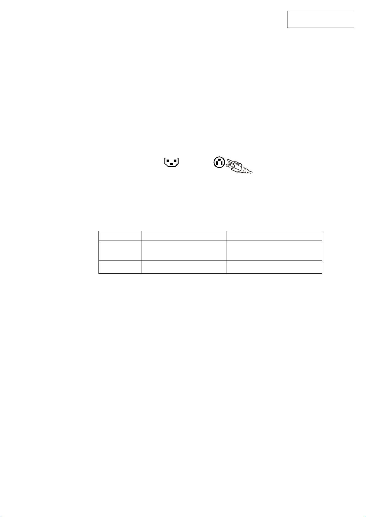
IMPORTANT NOTICE CONCERNING POWER CORD SELECTION
The specific power cord for this HD TV is enclosed and has been selected according to the country
of destination and must be used to prevent electric shock. Use the following guidelines if it is
necessary to replace the original cord set, or if the cord set is not enclosed. The female receptacle
of the cord set must meet IEC-60320 requirements and should look like Figure A1 below:
Figure A1 Figure A2
For the United States and Canada
In the United States and Canada the male plug is a NEMA5-15 style (Figure A2), UL Listed, and
CSA Labeled. For LCD TVs that are placed on a desk or table, type SVT or SJT cord sets may be
used. For LCD TVs placed directly on the floor, only SJT type cord sets may be used. The cord set
must be selected according to the current rating for the LCD TV. Please consult the table below for
the selection criteria for power cords used in the United States and Canada.
Cord Type Size of Conductors in Cord Maximum Current Rating of Unit
SJT
SVT
18 AWG
16 AWG
14 AWG
18 AWG
17 AWG
10 Amps
12 Amps
12 Amps
10 Amps
12 Amps
3
Page 4

LC-20SH21U
FCC Compliance Statement
This equipment has been tested and complies with the limits for a Class B digital device, pursuant
to part 15 of the FCC Rules. These limits are designed to provide reasonable protection against
harmful interference in a residential installation. This equipment generates, uses, and can radiate
radio frequency energy, and may cause harmful interference to radio communications if not
installed and used in accordance with the instructions. However, there is no guarantee that
interference will not occur in a particular installation. If this equipment does cause harmful
interference to radio or television reception, which can be determined by turning the equipment off
and on, the user is encouraged to try to correct the interference by one or more of the following
measures:
FCC Warning
To assure continued FCC compliance, the user must use a grounded power supply cord and the
provided shielded video interface cable with bonded ferrite cores. If a BNC cable is used, use only
a shielded BNC (5) cable. Also, any unauthorized changes or modifications not expressly
approved by SHARP CORPO RATION will void the user's authority to operate this device.
• Reorient or relocate the receiving antenna.
• Increase the separation between the LCD TV and receiver.
• Connect the equipment into an outlet on a circuit different from that to which the receiver is
connected.
• Consult the SHARP Service Center or an experienced radio/TV technician for assistance.
4
Page 5
LC-20SH21U
2. Specifications
Model Name LC-20SH21U
Panel Type
Viewing Angles 160° (H) / 140° (V)
Input Signal Video/Audio VGA Analog * 1 (75 ohms, 0.7 Vp-p)/Mini-Stereo *1
H/V separated (TTL) for PC; fh: 30-48 kHz, fv: 50-75 Hz
HDMI-HDCP *1 / RCA (L/R) stereo *1
TV system antenna / NTSC & ATSC *1 in USA(F type)
YPbPr * 1 / RCA (L/R) Stereo * 1
AV2 * 1 / RCA (L/R) Stereo * 1
Composite * 1 / S–Video * 1 / RCA (L/R) stereo * 1
Output Signal RCA (L/R) Stereo * 1;SPDIF (PCM/RAW) *1
HDTV Compatibility 480i, 480P, 720P, 1080i
The best TVs use the best technology: ATI inside your TV for The Ultimate Visual
Video Engine
PC Compatible Recommended 1360 x 768@60Hz(reduce blanking)
H = 30~48KHz V= 50~75 Hz
Experience.™ Your new Sharp TV is powered by ATI’s Xilleon™ image processing chip
for the true high definition cinematic experience. Enjoy your new Sharp TV with ATI inside.
20" (20" viewable diagonal area), TFT (Thin Film Transistor),
TN model, 1366 x 768 Normally White
1280 x 720@60Hz 720 x 400
1024 x 768@60Hz 640 x 480
Speaker Output 2.5w (x 2 Channels)
Power Voltage 120VAC, 60 Hz, 1.5A
Temperature Operating 0 to + 35° C (Hum. <90%)
(Note A) Storage -20 to +60 oC (Hum.< 35 %)
Humidity (Relative) Operating 20 to 90% no n-condensing. (Ta< 35%)
(Note A) Storage 10 to 90% non-condensing. (Note A)
Wet-bulb temperature should be 39 oC Max. (Ta> 40oC)
Note A: The temperature and relative humidity range is shown in right side
Altitude Operating 0 to 3,000 m
Storage 0 to 12,000m
Dimensions Physical 509 mm (W) x 408 mm (H) x 203 mm (D)
Weight Net / Gross 6.4 kg / 8.3 kg
Regulations UL/C-UL, FCC-B, UL(UL60065) / C-UL,ICES-003,BETS-T
Consumption
(DC Power)
Preset Timing Mode:
Selects timing mode at 1360 x 768 / 60 Hz (reduce blanking) or recommended timing, when you set the graphics card
in your computer.
Note: Product Specifications are subject to change without notice.
On
DC OFF
Power saving
70w (Blue LED)
0.5w (LED off)
14w (Amber LED)
5
Page 6

LC-20SH21U
3. Servicing Environment
1. This LCD TV should be used only with the power source type identified on the package and
2. Service the LCD TV in a room with low humidity and free of dust.
3. Place the LCD TV on a firm, level surface. Subjecting the LCD TV to a drop or sharp impact
4. If necessary, clean the LCD TV with a slightly damp cloth using clean water.
5. In the event that the powered LCD rapidly heats, or emits unusual smells or noises,
6. To avoid electrical hazard, make sure that the LCD TV is fully assembly the casing closed, and
7. Internal components of LCD display may be damaged by electrostatic discharge(ESD). Carry
8. Before opening the housing, disconnect the product from all power source and remove any
User’s Guide
may cause severe damage to thin glass, plastic surface materials, and internal components.
Disconnect the LCD TV fro m the power source before cleaning. DO NOT use ammonia -based
cleaning products.
immediately disconnect the LCD TV From the power source.
the screws tightened completely before plugging in LCD TV for testing.
out repairs in an ESD-protected work shop. If no such workshop is available, wear an
antistatic wrist strap or touch a highly conductive metal object.
connecting cable. If the display has not been disconnected from the power outlet before being
opened, there is a danger to life through electric shock. These is also a risk of damage to the
components
6
Page 7
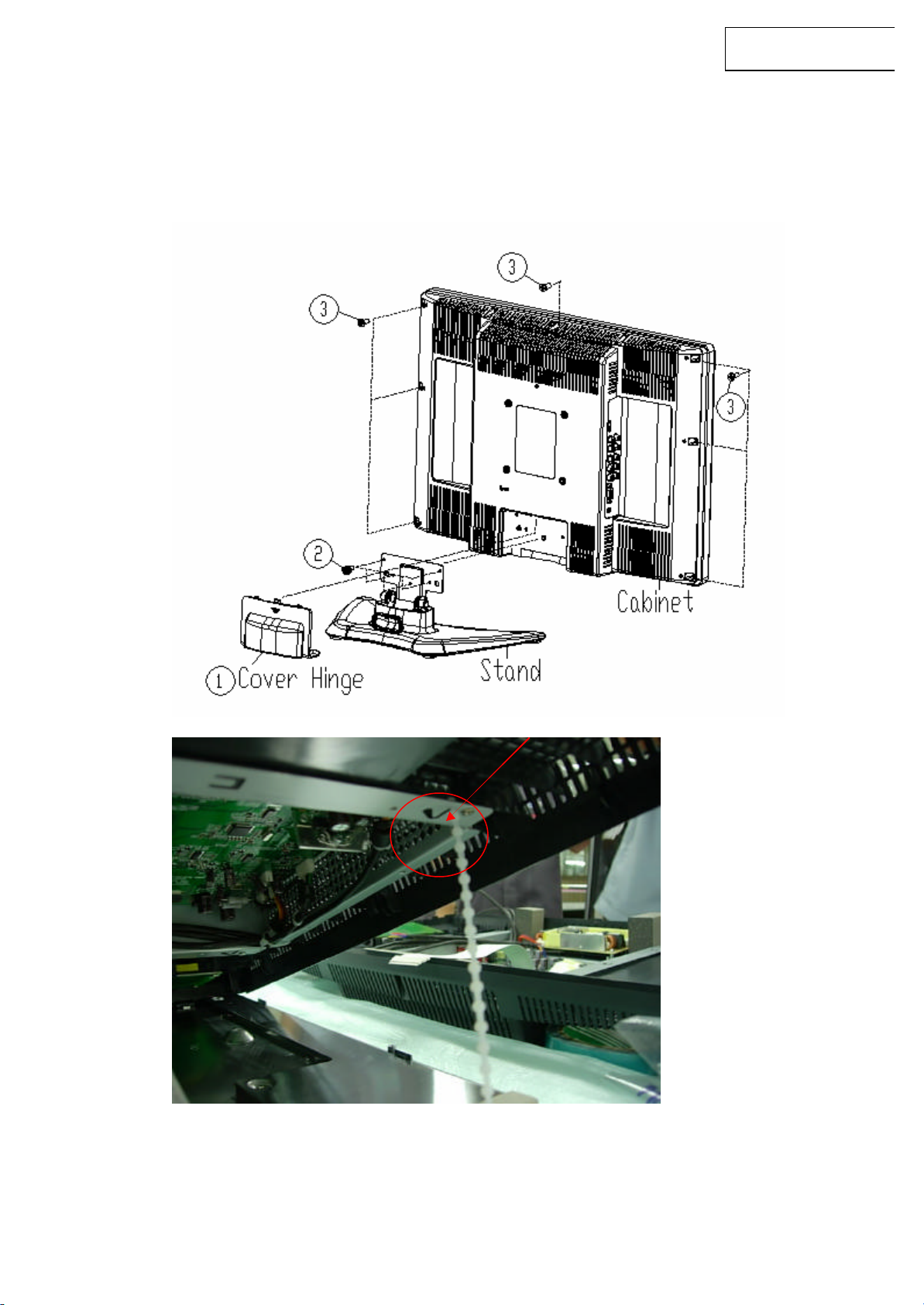
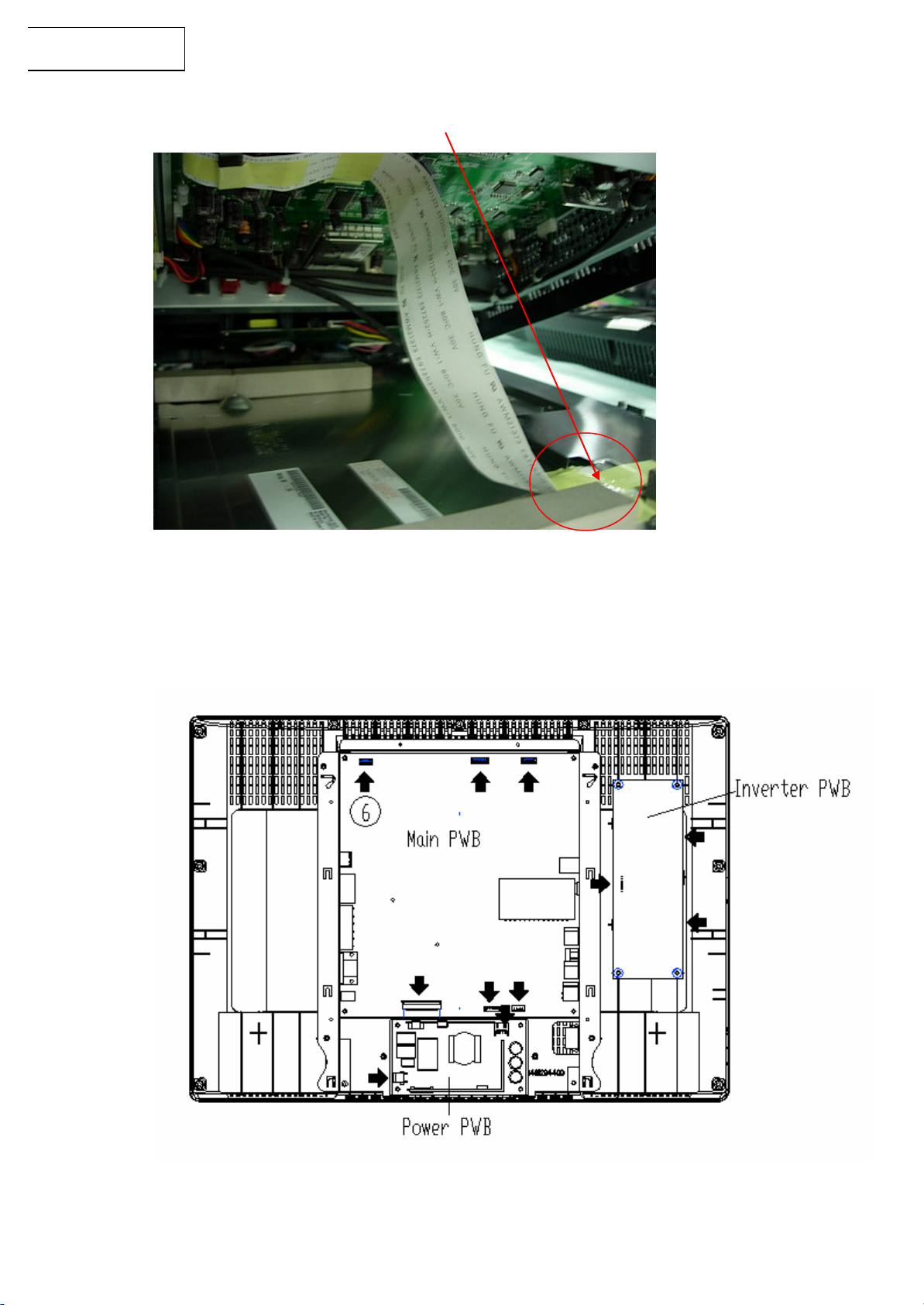
4. Disassembly of Major Parts
1. Remove the cover hinge.
2. Remove the stand fixing screws (5 pcs ).
3. Remove the Cabinet fixing screws (7 pcs).
LC-20SH21U
4. After opening the Cabinet, remove the cable tie first.
7
Page 8
LC-20SH21U
5. Disconnect the Panel FFC cable connector.
6. Disconnect all the connectors from the PWB’s of Cabinet module.
8
Page 9
LC-20SH21U
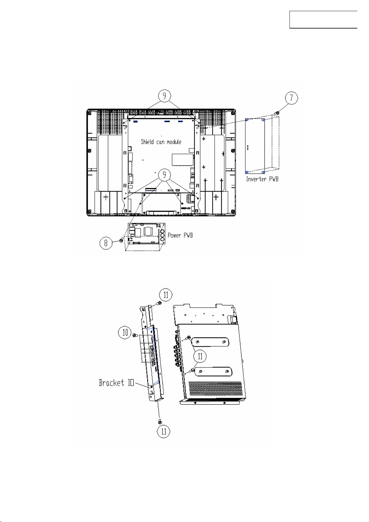
7. Remove the Inverter PWB fixing screws (4 pcs).
8. Remove the Power PWB fixing screws (4 pcs).
9. Remove the Shield can module fixing screws (6 pcs), then take out the
shield can module.
10. Remove the Left side IO fixing screws (5 pcs).
11. Remove the Bracket IO fixing screws (4 pcs).
9
Page 10
LC-20SH21U
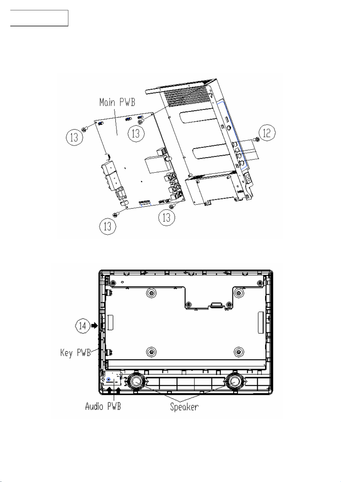
12. Remove the Right side IO fixing screws (4 pcs).
13. Remove the Main PWB fixing screws (4 pcs).
14. Disconnect all the connectors from the PWB’s of Bezel module.
10
Page 11

15. Remove the Key PWB fixing screws (2 pcs).
16. Remove the Audio PWB fixing screws (1 pcs).
17. Remove the Speakers fixing screws (4 pcs).
LC-20SH21U
11
Page 12
LC-20SH21U
INVERTER
POWER BD
4
PIN
AUO 20” WXGA
8
PIN wire
30PIN
6
vThe inverter Lamp wire, please c
onnect the
CN1
CN200
CN413 CN415
CN1
CN9505
SPEAKER
5. Wiring Diagram
KEY BD
CN901
CN301 6pin
CN303 7pin
CN809 5pin
6 PIN
6 PIN wire
5 PIN wire
5 PIN wire
60W
Main BD
wire
2pin
CN2 4pin
1 4pin
8pin
AC socket 2pin
AC 120V 60Hz
T200XW02
LAMPS
FFC
BD
CN2
CN3
CN4
8pin
CN5
CN6
CN7
12
10pin
IR BD
CN9506 4pin
4 PIN
2.5W X 2
Panel
WHITE color wire to CN2/CN7, PINK color wire
to CN3/CN6, BLUE color wire connect to
CN4/CN5.
Page 13
LC-20SH21U
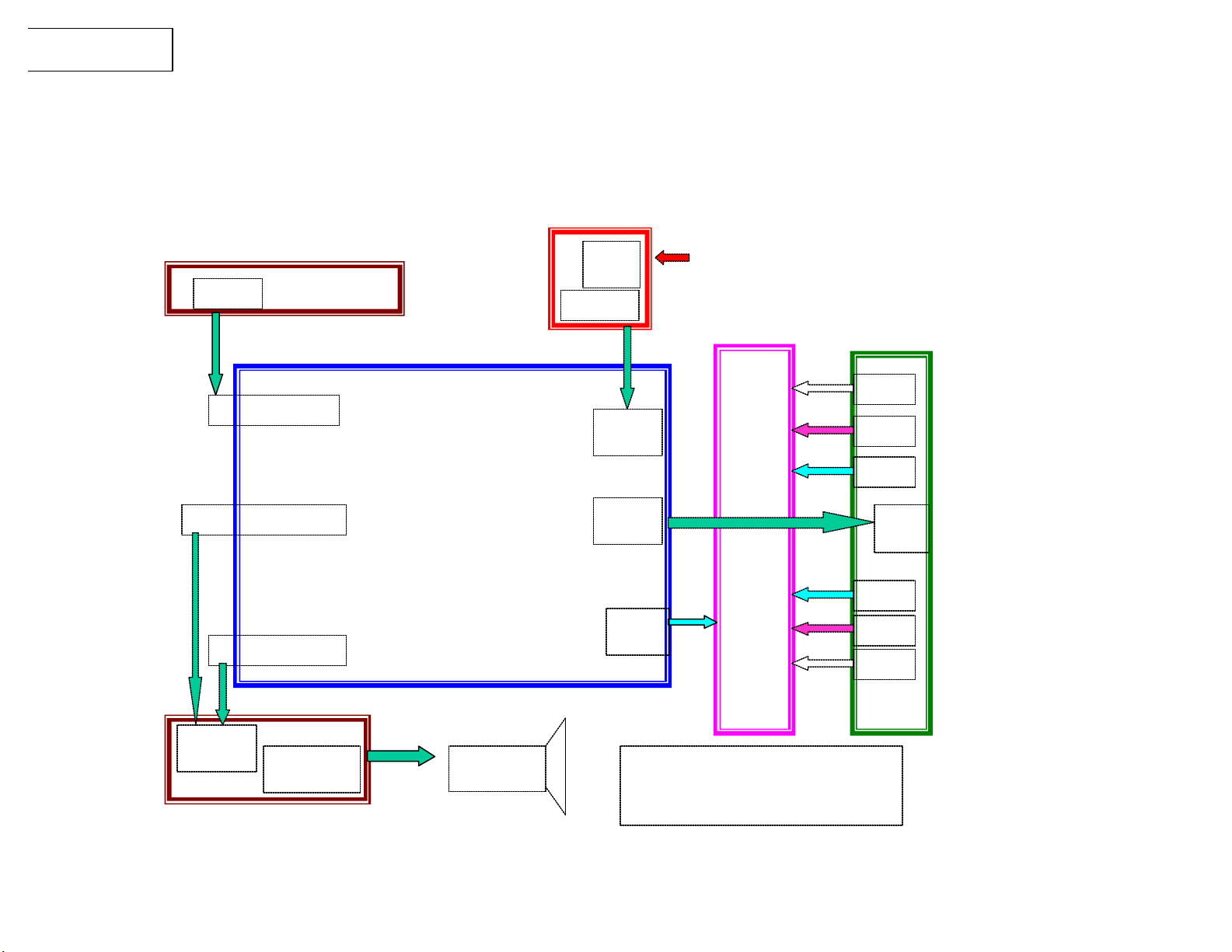
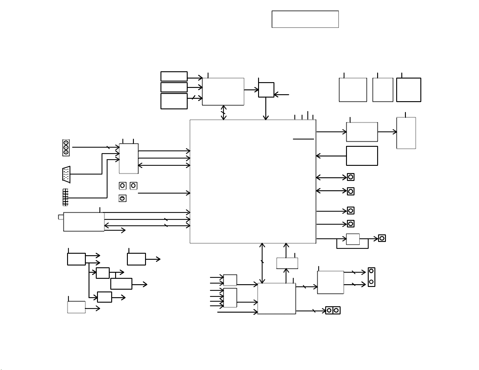
6. Block Diagram
COMPONENT
CN604
VGA
CN601
HDMI
CN701
TM701/TM702
PHILIPS/LG
NTSC+ATSC TUNER
+12V
IC2001
BA9741F
+12V
IC2004
MC7805
TMDS*4
+5V
P/0.42A
LG/0.24A
IC2003
AIC1084
LD1085
Y/PB/PR
3
CN609 CN613
AV1
1.2V/3A
5V/5A
IC2007
FOR TUNER
5V
AD9380
IC2008
AIC1084
+1.8V+3.3V
IC602
CN609
S-Video
NTSC_CVBS
DIGITAL IF
TUNER_I2C
TVSOUND (SIF)
5VSB
IC2006
LD1117S
3.3V
2.6V
FOR ATI & DDR
RGB/24BIT
I2S
I2C
AV2 FRONT SIDE
3.3V
1.8V
CN301
KEYPAD
CN303
IR & LED
CN302
ATmeg48
PROGRAM
DOENLOAD
2
2
FOR MCU
ADC
3
COMPONENT R/L
AV R/L *2
VGA R/L
HDMI R/L
ATSC R/L
TVSOUND (SIF)
+3.3V
Microcontroller
IC301
ATmeg88
2 UART
IC806
4052
IC805
4052
+3.3V
IC401
ATI X240
INPUT1
INPUT2
IC407
RESET
I2C I2S OUT I2S IN
2
IC802
74LVC125A
32K
IC803
Micronas
MSP3445G
4CH
JTAG RESET
+2.6V
+1.8V
+3.3V
+1.2V
1.2V/1.8A/2.16W
1.8V/0.37A/0.67W
2.6V/0.42A/1.05W
3.3V/0.01A/0.03W
3.91W
ATI_S/PDIF
+3.3V
+5V
R/L
2
+2.6V
IC501,IC502
MT46V32M16
DDR MEMORY
64MBYTES
+3.3V
24BIT/RGB OUT TMDS*4
RXD/TXD_B
RXD/TXD_C
+16V
IC811
TPA1517
2
IC505
THC63LVDM83A
28Bits LVDS
CN402
JTAG CONNECT
DEBUG PORT
CN404
CN405
CN407
I2C INPUT PORT
CN401
USB PORT
IC813
74HC04
2
2
CN805
R/L
RS232 DEBUG
FACTORY MODE
CN809
ANALOG R/L OUT
+3.3V+3.3V
IC503
M25P40 K9F2808U0C
EEPROM
4MBITS
CN810
R
IC405
NAND FLASH
128MBITS
+5V
CN413
PANEL
1366X768
S/PDIF OUT
BY OPTICAL TRANSMITTING
SPEAKER 3W
HEADPHONE R/L OUT
L
13
Page 14

LC-20SH21U
Balance
If the Main board or LCD Panel is replaced, white balance alignment must be performed. The
adjustment procedure should be done as following.
Alignment equipment:
1. ASTRO VG859 series.
2. MINOLTA CA210
Please set the LCD TV to enter Factory mode first, then proceed to alignment procedure.
Ø
1. PC mode (INPUT5 (PC)).
7. Alignment Procedure for White
Perform ADC CALIBRATION at PC and COMPONENT inputs.
1.1 Preset condition.
1.1.1 Select in INPUT5 (PC), and analog RGB (D -SUB 15 pin), input 1024x768 / 60Hz
48K (VG859, T#856), 8 x color BAR (1 00%) + 16 Gray Scale (100%), (VG859,
P#918) (input level 100IRE 0.7Vp-p). See Figure 1
100% color BAR
100% white BAR
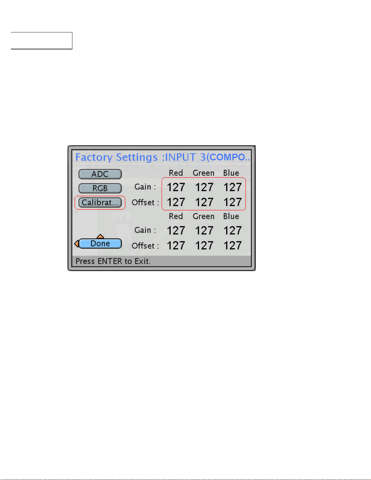
1.1.2 Press “MENU” button to select “Setting”, then enter “Factory Settings ” by “Enter”
key, and enter “Calibration” to start perform ADC Calibration.
Fig.1
14
Page 15

LC-20SH21U
1.1.3 After the calibration function , please check the Gain/Offset value .
1.1.3.1 If the Red, Green, Blue Gain/Offset data are same ” 127”,it means this
set not yet do the ADC calibration, it must do the calibration function again.
1.1.3.2 If the Red, Green, Blue Gain data are out of the 80-135,Offset data are too
high(near 255) or too low(near 0), it means hardware or test pattern/timing NG.
1.2 32grays pattern check:
1.2.1 Input 1360x768 / 60Hz (reduce blanking), 32 grays scale pattern at 100IRE, adjust
brightness 25, contrast 40 (OSD setting).
1.2.2 In Color Low/Middle/High temp. (6500°K ,9300 °K,12000°K) the 32 levels of gray
need be visible.
1.2.3 Input 1360x768 / 60Hz & 32 grays pattern at 100IRE, adjust brightness 25 , contrast
50 (OSD setting).
1.2.4 In Color Low/Middle/High temp. (6500°K ,9300°K,12000°K) 32grays need > 4 level
saturation.
15
Page 16
LC-20SH21U
2. Component mode (INPUT 3(COMPONENT))
1.3 Luminance test: (To select “custom mode” by entry “picture setting”)
1.3.1 Input 1360x768 / 60Hz full white pattern at 100IRE .
1.3.2 Adjust contrast & brightness & Backlight to Max., (OSD setting).
the Y > 315cd/m2 ( Bmax ). in color temp. Middle/Low mode,
the Y > 270cd/m2 ( Bmax ). in color temp. High mode.
( 450*0.7=315/450*0.6=270)
2.1 Input 720P (T#976), 8 x color BAR (100%) + 16 Gray Scale (100%), (VG859, P#918)
(input level 100IRE 0.7Vp-p), (see Figure 1).
2.2 Select Setting -> Factory Settings->Calibration then do the ADC Calibration
.2.3 After the calibration function, please check the Gain/Offset value.
2.3.1 If the Red, Green, Blue Gain/Offset data are same” 127 ”, it means this
set not yet do the ADC calibration, it must do the calibration function again.
2.3.2 If the Red, Green, Blue Gain data are out of the 39-88, Offset data are too high
(near 255) or too low (near 0), it means hardware or test pattern/timing NG.
16
Page 17

LC-20SH21U
2.4 Input 480P (T#978), 8 x color BAR (100%)+ 16 Gray Scale (100%), (VG859, P#918)
(input level 100IRE 0.7Vp-p), (see Figure 1).
2.5 2Select Setting -> Factory Settings ->Calibration then do the ADC Calibration
2.6 After the calibration function, please check the Gain/Offset value.
2.6.2 If the Red, Green, Blue Gain/Offset data are same ” 127”, it means this
set not yet do the ADC calibration, it must do the calibration function again.
2.6.3 If the Red, Green, Blue Gain data are out of the 39-88, Offset data are too high
(near 255) or too low (near 0), it means hardware or test pattern/timing NG.
2.7 Grays pattern check:
2.7.2 Input 480P/720P, 32 grays pattern at 100IRE, adjust brightness 25, contrast 40
(OSD setting).
2.7.3 In Color Low/ Middle/High temp. (6500°K ,9300°K,12000°K) the 32 grays need
be clear.
2.7.4 Input 480P/720P& 32 grays pattern at 100IRE, adjust brightness 25 , contrast 50
(OSD setting).
2.7.5 In Color Low/Middle/High temp. (6500°K, 9300°K, 12000°K) 32grays need > 4
level saturatio n.
2.8 Luminance test: (To select “ custom mode” by entry “picture setting”)
2.8.2 Input 480P/720P full white pattern at 100IRE .
2.8.3 Adjust contrast & brightness & Backlight to Max., (OSD setting).
the Y > 315cd/m2 ( Bmax ). in color temp. Middle/Low mode,
the Y > 270cd/m2 ( Bmax ). in color temp. High mode.
( 450*0.7=315/450*0.6=270)
Ø Perform White Balance Alignment after Finishing ADC Calibration.
n 1. Test condition :
a. Measurement point: Center.
b. Measurement direction: Vertical to the screen.
17
Page 18

LC-20SH21U
n 2. Check criteria:
n 3. Adjustment criteria
c. Luminance color meter: Minolta CA210 color analyzer.
There are four user selectable color setting as specified below:
High color temp (12000°K)
x = 0.272 ± 0.02 y = 0.278 ± 0.02.
Middle color temp (9300°K)
x = 0.286 ± 0.02 y = 0.294 ± 0.02
Low color temp (6500°K)
x=0.314 ± 0.02 y = 0.324 ± 0.02
User color temp (9300°K)
x = 0.286 ± 0.02 y = 0.294 ± 0.02
There are four user selectable color setting as specified below:
High color temp (12000°K)
x = 0.272 ± 0.005 y = 0.278 ± 0.005.
Middle color temp (9300°K)
x = 0.286 ± 0.005 y = 0.294 ± 0.005
Low color temp (6500°K)
x = 0.314 ± 0.005 y = 0.324 ± 0.005
User color temp (9300°K)
x = 0.286 ± 0.005 y = 0.294 ± 0.005
n 4. White Balance adjustment procedure
4.1 Warm up the LCD TV about 30 minutes.
4.2 Set the LCD TV to Factory mode (By OSD), select input source to INPUT 4 (HDMI) and
Set pattern generator to HDMI 1360x768 60Hz timing with white pattern (White signal
level is 90%=90IRE).
4.3 Select custom mode, Contrast = 40, Brightness = 25 (OSD menu).
4.4 Select to High color temp. 12000°K .
4.5 Adjust RGB gain to meet the x=0.272 +/-0.005 and y=0.278+/-0.005.
18
Page 19

LC-20SH21U
4.6 Select to Middle color temp. 9300K °K .
4.7 Adjust RGB gain to me et the x=0.286 +/-0.005 and y=0.294 +/-0.005.
4.8 Select to Low color temp. 6500 °K .
4.9 Adjust RGB gain to meet the x=0.314 +/-0.005 and y=0.324 +/-0.005.
4.10Exit the Factory mode and Power off/on the LCD TV , then use the item 2 Check
criteria to confirm All INPUT( TV/INPUT1-5) adjustment is well saved.
Note:
1. Do not adjust the RGB offset function.
2. Do not allow to increase RGB gain bigger than 127, only allow to decrease the RGB gain to
meet adjustment criteria.
3. There are at least 1 of RGB gain should be keeps at 127 in each adjusted colors.
Ø Entry “Factory Info” mode to check TV set information
19
Page 20

LC-20SH21U
l I/O ports Test :
Ø Input 1: Video
Connect the Composite Video to a legacy video device such as a VCR or video game
system.
Ø Input 1: S-Video
Connect S-Video to a legacy vi deo device such as a VCR or video game system. If both
terminals are connected, S-Video terminal takes a priority
Ø Input 1: Audio (Right / Left)
Connect an external audio source to this jack (Audio (R/L)). This connection supports either
S-Video or Video input.
Ø Input 2: Video
Connect the Composite Video to a legacy video device such as a VCR or video game
system.
Ø Input 2: Audio (Left / Right)
Connect an external audio source to this jack.
Ø Input 3: YPbPr
Connect external video devices with component output to these jacks.
Ø Input 3: YPbPr Audio (Left / Right)
Connect an external audio source to this jack.
Ø Input 4: HDMI -HDCP
Connect to an external video device such as HD Digital cable/satellite receiver, HD
Set-Top-Box, Media Ce nter PC, or DVD player.
Ø Input 4: HDMI Audio (Left / Right)
Connect the audio input if you using a DVI-to-HDMI adaptor.
Ø Input 5 (PC IN): Audio
Connect to the Audio out (Green) from a computer.
Ø Input 5 (PC IN): Analog RGB
Using a 15-pin VGA cable, connec t to a computer or other device with a VGA output.
Ø SPDIF Output (Digital Audio Out)
Connect this output to an external stereo audio amplifier, receiver or surround sound
processor with SPDIF optical Input .
Ø Audio Output: Right / Left
Connect this output to an external stereo audio amplifier, receiver or surround sound
processor with R/L audio Inputs.
Ø ANT.: RF-input
Connect the LCD TV to an over-the-air antenna or cable service to view NTSC or ATSC
20
Page 21

LC-20SH21U
(HDTV) content .
Ø Factory Service Port
Refer to “Firmware Upgrade Procedure ” (page 22).
Ø AC IN (Power)
Connect the power cord from AC IN to a power source.
21
Page 22

LC-20SH21U
Ø Firmware Upgrade
8. Firmware Upgrade Procedure
Step 1 Press the button of LCD TV to turn power off.
Step 2 Plug the USB drive for service to USB port located on the ride side
of LCD TV
Step 3 Press the POWER button on LCD TV to turn power on. The upgrade
will start automatically .
Step 4 Screen will show Firmware upgrade done when upgrade completed.
Step 5 Press the POWER button on LCD TV to turn power off
Step 6 Remove the USB drive for service from USB port located on the ride
side of LCD TV.
Ø How to reset PIN number
Step 1 Go to Setting on the menu list.
Step 2 Select Reset All. Enter "0826" as PIN number to access this
function.
Step 3 Select Reset to reset TV to factory default status. PIN number will
also be reset to "0000"
22
Page 23

LC-20SH21U
9. Troubleshooting analysis
Light On
Abnormal
Chrominance
Inverter Board
Power Board
Change
NG
Defect Mode
Failure Analysis Repair Testing
Test
Display
Missing Line
Bright Dot
Dark Dot
Check PCBA
Check Panel
M/B Change
Panel Change
Backlight
Light Leakage
Check Panel
Panel Change
non-uniformity
Image Sticking
Brightness Spot
Particle
Dot Defect
A
No Display
Noise
Check PCBA
Check Panel
Check PCBA
Check Panel
Next Step
M/B Change
Panel Change
M/B Change
Panel Change
Test
Complete
23
Page 24

LC-20SH21U
A
Image is too
Gray Value
R.G.B. Display
Display Shut
Power on
Check D
-
sub
Inverter Board
Change
A
Power Board
Check Panel
Cable
Check PCBA
Panel Cable
Change
Power Board
D-sub Cable
Defect Mode Failure Analysis
Flicker
Display
Down
VGA No Image
Display
Abnormal
Check PCBA
Check PCBA
Check Panel
Check PCBA
Check Panel
Check PCBA
Cable
Check PCBA
Next Step
M/B Change
Panel Change
M/B Change
Panel Change
M/B Change
M/B Change
Panel Change
M/B Change
Change
M/B Change
Repair Testing
Test
24
Complete
Page 25

LC-20SH21U
Other
Display flicker
Cannot use
Remote Control or
Defect Mode
Failure Analysis
Repair Testing
Abnormal
Display
NG
(tapping)
Remote Control
Check PCBA
Check Panel
Check Remote
Check PCBA
Next Step
M/B Change
Panel Change
Battery Change
M/B Change
IR Board Change
Test
Complete
25
Page 26

LC-20SH21U
Video
AV, SV, CV
Defect Mode Failure Analysis
Repair Testing
Abnormal
(AV, SV,
CV)
AV: Composite Video
SV: S-Video
CV: Component Video
No image
Check PCBA
Check Cable
M/B Change
Cable Change
Complete
Test
26
Page 27

LC-20SH21U
10. Exploded View
27
Page 28
LC-20SH21U
28
Page 29

LC-20SH21U
11. Part List
Ø Mechanical Parts :
Ref. No. Part Number Description
1 9NK3081501800 CABLE FFC L330 WHT T1
2 9NK3100300600 SCREW M M3*0.5*6 PAN C S+P S20C ZN
3 9NK3100301200 SCREW M M3*0.5*12 PAN C S+P S20C ZN
4 9NK3109019400
5 9NK3109019500
6 9NK3109161400
7 9NK3205117500 NAME PLATE AL 45*6.2 T1 LT20FGN 26AAB
8 9NK3243006800 PAD RUBBER 94V0 28*20*3 GRAY
9 9NK3244093300 INSULATOR PC 130*71*0.4 BLACK
10 9NK3262511900 LABEL LOGO ART PAPER 9.7*9.5 LT20FGN 26A
11 9NK3262512000 LABEL LOGO ART PAPER 43*9.8 LT20FGN 26AA
12 9NK3264521300 LABEL CONNECTOR -L PC 61.45*193.65 T.254
13 9NK3264521400 LABEL ID POLYESTER 100*70 T.1 LT20FGN 26
14 9NK3264521500 LABEL CONNECTOR -R PC 63*193.65 T.25 LT20
15 9NK3360266300 R/C ABS 94V0 SW-009 20VRA1AT BK-017R
16 9NK3360266500 COVER HINGE HIPS 94V0 P20VBA1AT BK-017R
17 9NK3360266800 FUNCTION KEY HIPS 94V0 BK-017R P20VFA1AT
18 9NK3368251900 BASE ASSY LT20FGN 26AAB P20VBA1AT
19 9NK3368601500 F/B ASSY LT20FGN 26AAB P20VFA1AT
20 9NK3460293700 BRACKET IO SECC 322.6*45.8*30*0.8
21 9NK3461005900 PLATE SUS 11.6*9.6*0.5*0.5
22 9NK3461294400 SHIELD CAN SECC 324.6*244*46.6*0.8
23 9NK3616012500 SOCKET ASSY LT20FGN 26AAA
Ø Electronic Parts:
SCREW T f 3*1.06*9 FF C S18C NI
SCREW T f 3*2.7*10 FF C S18C ZN BLK
SCREW T f 3*1.27*10 PAN C S20C ZN BLK
Ref. No. Part Number Description
E1 9NK3791021900 SPEAKER ASSY LT20FGN 26AAB
E2 9NK4900210880 POWER SUPPLY 90 -265VAC 3.75A TV USE
E3 9NK4900510180 DC-AC INVERTER 16V 2.3A 1927V 7mA
E4 9NK5052000902 PANEL LCD LVDS 20 1366*768 WXGA 6EA"
E5 9NK5600600283 PWB ASSY FUNCTION KEY BD LT20FGN 26AAB
E6 9NK5600600285 PWB ASSY IR BD LT20FGN 26AAB
E7 9NK5600600286 PWB ASSY MAIN BD LT20FGN 26AAB
29
Page 30

LC-20SH21U
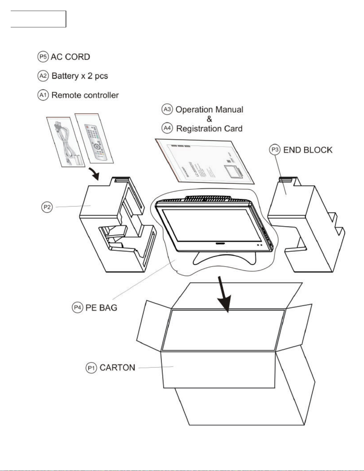
Ø Accessories:
Ø Packing Parts:
Ref. No. Part Number Description
A1 9NK5041814100 Remote Control
A2 9NK0991210404 "AA" size Battery (x2)
A3 9NK5010055000 MANUAL OPERATION LT20FGN 26AAB LC-20SH21
A4 9NK5010054900 CARD REGISTRATION LT20FGN 26AAB LC-20SH2
Ref. No. Part Number Description
P1 9NK3513501600 CARTON PAPER 567*261*462
P2 9NK3501400300 END BLOCK EPS 441*253*200
P3 9NK3501400400 END BLOCK EPS 441*253*200
P4 9NK3501382000 BAG PE 600*800
P5 9NK3090210800 AC POWER CORD 2P #18*2C L1800 BLK
30
Page 31

LC-20SH21U
Aug. 2006 Printe
d in Thailand
Design :
COPYRIGHT © 2006 BY SHARP CORPORATION
ALL RIGHTS RESERVED.
No part of this publication may be reproduced,
stored in a retrieval system, or transmitted in
any form or by any means, electronic, mechanical,
photocopying, recording, or otherwise, without
prior written permission of the publisher.
Design and Production Information
OEM
Production : OEM
SHARP CORPORATION
AV Systems Group
CS Promotion Center
Yaita, Tochigi 329-2193, Japan
31
 Loading...