

Page 1
LC-20E1E
SERVICE MANUAL
S72M2LC20-E1E
LCD COLOUR TELEVISION
MODEL
In the interests of user-safety (Required by safety regulations in some countries) the set should be restored
to its original condition and only parts identical to those specified should be used.
CONTENTS
» IMPORTANT SERVICE SAFETY PRECAUTION ........................................................................................2
» SPECIFICATIONS ........................................................................................................................................3
» OPERATION MANUAL .................................................................................................................................4
» DIMENSIONS ...............................................................................................................................................6
» REMOVING OF MAJOR PARTS..................................................................................................................7
» ADJUSTING PROCEDURE OF EACH SECTION .....................................................................................11
» TROUBLE SHOOTING TABLE ..................................................................................................................14
» CHASSIS LAYOUT.....................................................................................................................................20
» BLOCK DIAGRAM......................................................................................................................................22
» OVERALL WIRING DIAGRAM ...................................................................................................................24
» DESCRIPTION OF SCHEMATIC DIAGRAM .............................................................................................26
» SCHEMATIC DIAGRAM .............................................................................................................................27
» PRINTED WIRING BOARD ASSEMBLIES................................................................................................50
» REPLACEMENT PARTS LIST ...................................................................................................................61
» PACKING OF THE SET..............................................................................................................................75
LC-20E1E
Page
SHARP CORPORATION
Page 2
LC-20E1E
2
2
IMPORTANT SERVICE SAFETY PRECAUTION
Ë
Service work should be perfomed only b y qualified service technicians who are thoroughl y
familiar with all safety checks and the servicing guidelines which follow:
WARNING
1. For continued safety, no modification of any circuit
should be attempted.
2. Disconnect AC power before servicing.
CAUTION: FOR CONTINUED PROTECTION
AGAINST A RISK OF FIRE REPLACE ONLY WITH
SAME TYPE F1(T1.25AL, 250V), F2(T1.25AL, 250V),
F6700 (T1.25AL, 250V), F6701 (T1.25AL, 250V),
F6702 (T1.25AL, 250V), F6703 (T1.25AL, 250V) AND
F6704 (T1.25AL, 250V) FUSE.
BEFORE RETURNING THE RECEIVER
(Fire & Shock Hazard)
Before returning the receiver to the user, perform
the following safety checks:
1. Inspect all lead dress to make certain that leads are
not pinched, and check that hardware is not lodged
between the chassis and other metal parts in the
receiver.
2. Inspect all protective devices such as non-metallic
control knobs, insulation materials, cabinet backs,
adjustment and compartment covers or shields,
isolation resistor-capacitor networks, mechanical
insulators, etc.
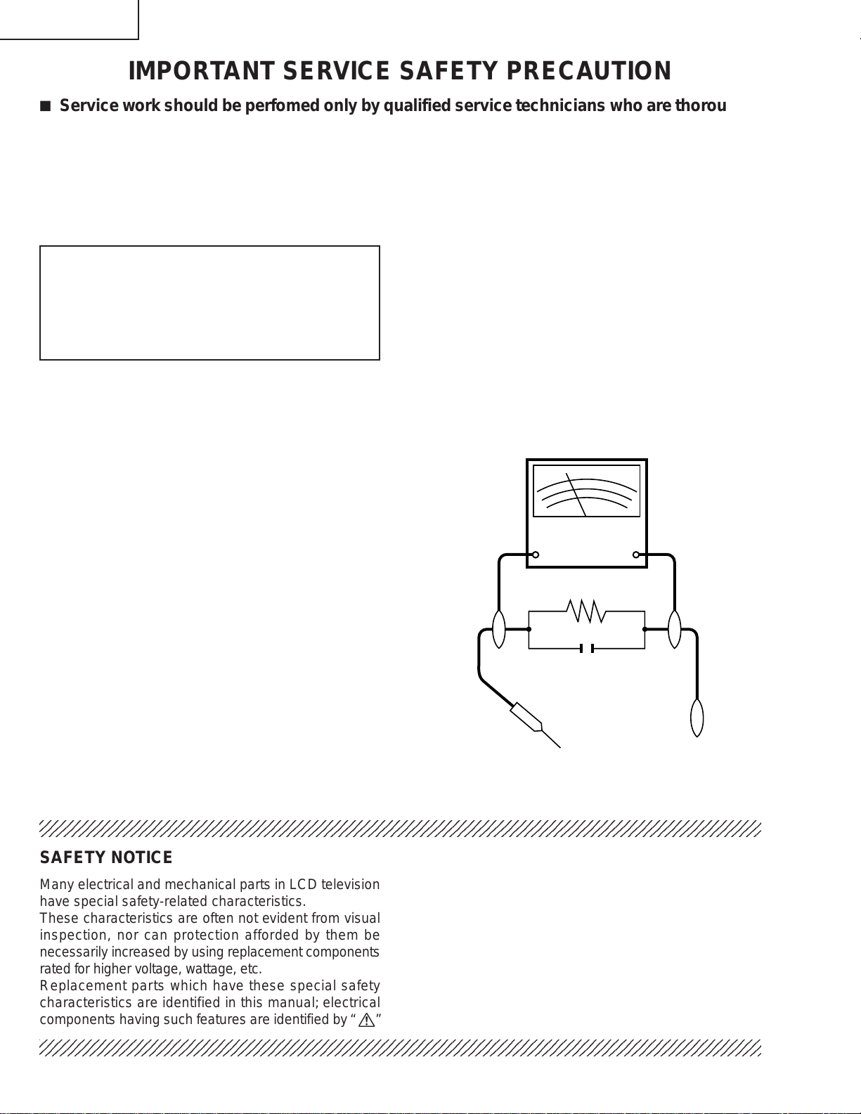
3. To be sure that no shock hazard exists, check for
leakage current in the following manner.
• Plug the AC cord directly into a 110~240 volt A C outlet,
and connect the DC power cable into the receiver's
DC jack. (Do not use an isolation transformer for this
test).
• Using two clip leads, connect a 50k ohm, 10 watt resistor
paralleled by a 0.15µF capacitor in series with all
exposed metal cabinet parts and a known earth ground,
such as electrical conduit or electrical ground connected
to an earth ground.
• Use an AC voltmeter ha ving with 5000 ohm per volt, or
higher, sensitivity or measure the AC voltage drop
across the resisor.
• Connect the resistor connection to all exposed metal
parts having a return to the chassis (antenna, metal
cabinet, screw heads, knobs and control shafts,
escutcheon, etc.) and measure the AC voltage drop
across the resistor.
All checks must be repeated with the AC cord plug
connection reversed. (If necessar y, a nonpolarized
adaptor plug must be used only for the purpose of
completing these checks.)
Any reading of 0.75V peak (this corresponds to 0.5
milliamp. peak A C .) or more is e xcessive and indicates
a potential shock hazard which must be corrected
before returning the monitor to the owner .
DVM
AC SCALE
50k ohm
10W
0.15 µF
TEST PROBE
TO EXPOSED
METAL PARTS
CONNECT TO
KNOWN EARTH
GROUND
234567890123456789012345678901212345678901234567890123456789012123456789012345678901234567890121
SAFETY NOTICE
Many electrical and mechanical parts in LCD television
have special safety-related characteristics.
These characteristics are often not evident from visual
inspection, nor can protection afforded by them be
necessarily increased by using replacement components
rated for higher voltage , w attage , etc.
Replacement parts which have these special safety
characteristics are identified in this manual; electrical
and shaded areas in the
Schematic Diagrams.
For continued protection, replacement parts must be
identical to those used in the original circuit.
The use of a substitute replacement parts which do not
have the same safety characteristics as the factory
recommended replacement parts shown in this service
manual, may create shock, fire or other hazards.
components having such features are identified by “ å”
234567890123456789012345678901212345678901234567890123456789012123456789012345678901234567890121
2
Replacement Parts Lists and
Page 3

SPECIFICATIONS
Items 20" LCD COLOUR TV, Model: LC-20E1E
LCD panel
LCD panel size
Number of dots 921,600 dots
Video colour system PAL/SECAM/NTSC
TV TV-Standard (CCIR) B/G, I, D/K, L
Function TV-Tuning System Auto preset 200 ch.
STEREO/BILINGUAL NICAM, IGR
AUTO PRESET Yes
CATV ~Hyper Band
Brightness 430 cd/m
Lamp life 60,000 hours
Viewing angles H: 170° V: 170°
Audio amplifier 2.5 W × 2
Speakers 4 × 7 cm 2 pcs.
Terminals AV-IN 1 RGB
AV-IN 2 S-VIDEO, VIDEO, AUDIO
OUT AUDIO
Antenna DIN
Headphones 3.5 mm ø jack (Rear)
OSD language English/German/French/Spanish/Italian/Swedish/Dutch
Power requirement DC 13 V, AC 110 V – 240 V, 50/60 Hz
Weight 7.1 kg
Accessories Operation Manual, Remote Control, Batteries,
Advanced Super View & BLACK TFT LCD
19.7"
2
AC adapter, AC cord, Cable clamp
LC-20E1E
Specifications are subject to change without prior notice.
3
Page 4
LC-20E1E
A
V-IN
1
R
G
B
A
V
-IN
2
S
-V
ID
E
O
V
ID
E
O
L
R
A
U
D
IO
P
O
W
E
R
IN
P
U
T
D
C
1
2
V
L
R
A
U
D
I
O
O
U
T
L
R
AU
D
IO
O
U
T
A
V
-IN
1
R
G
B
A
V
-IN
2
S
-V
ID
E
O
V
ID
E
O
L
R
A
U
D
IO
P
O
W
ER
IN
P
U
T
D
C
13
V
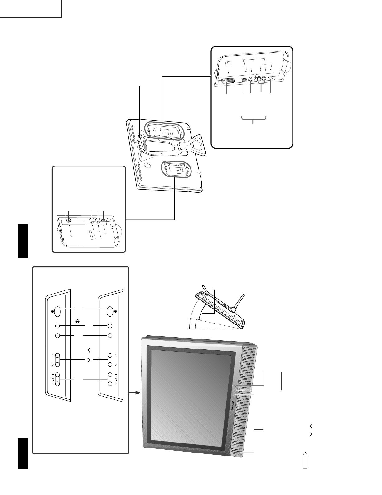
Carrying handle
POWER INPUT
(DC 12V : LC-13E1E/
LC-15E1E)
(DC 13V : LC-20E1E)
AV-IN 1
(21pin Euro-SCART)
S-VIDEO
VIDEO
AUDIO (L)
AUDIO (R)
AV-IN 2
Antenna
AUDIO OUT (L)
AUDIO OUT (R)
Headphones
Rear view
Terminals
CH
MENU
TV/VIDEO
CH
MENU
TV/VIDEO
Volume (–)/(+)
POWER/STANDBY indicator
A green indicator lights when the power is on and a red
indicator lights when in the standby mode (the indicator
will not light when the main power is off).
Speaker
Remote sensor window
Remote sensor indicator
A red indicator blinks when the TV set receives the
remote control signal.
Upper control panel
The screen can be adjusted
backwards to an angle between 12
degrees and 35 degrees. The screen
cannot be set up straight. When
changing the angle, make sure to
hold the stand and adjust the screen
to the best viewable angle.
Controls
Note:
Note:
• TV/VIDEO, CH(
)/( ), Volume (–)/(+) and MENU on the main unit have the same functions as the same buttons
on the remote control. Fundamentally, this operation manual provides a description based on operation using the
remote control.
• The LC-13E1E, LC-15E1E and LC-20E1E have different external dimensions and the positions where the names
of the buttons are displayed also differ but the same operating procedures are followed for all three models.
LC-20E1E
LC-13E1E
LC-15E1E
CH (
)/( )
MENU
TV/VIDEO
(MAIN POWER)
35°
12°
Adjustable range
OPERATION MANUAL
4
Page 5
E
CH
TV/VIDEO
REVEAL
H
OLD
EN
D
M
MENUSOUND
SU
B
TIT
LE
OK
OK, Programme Table
SUBTITLE
Displays the Teletext
Subtitle directly.
HOLD
Temporarily holds the
current Teletext page.
Mute
Switches the sound on and off.
Yellow,
Timer function Menu
Cyan, Status Display
Turns on the status display
when the menu is not
displayed.
TV/VIDEO
Switches the input source
between AV1, AV2 and
TV mode.
Channel Select
MENU
Displays the TV menu.
Volume (+)/(
-
)
Flashback
Returns to the previous
channel.
Red, Picture Menu
Upwards/ Downwards
Selection, zoom display
function (Teletext mode)
)
END
Returns to normal screen.
)
TEXT
Displays the Teletext mode
screen.
(Power)
SOUND
Switches the sound
mode.
REVEAL
Displays hidden information
such as solutions to riddles
and puzzles.
Right / Left Selection
SUBPAGE
Displays the Teletext
Subpage directly.
ROTATE
Rotates the display in every
direction.
BRIGHT
Selects the brightness
of the display.
Green, Sound Menu
SUBPAGE
TE
X
T
ROTATE
B
R
IG
H
T
T
CH ( )/( )
Displays previous/next page.
(Teletext mode)
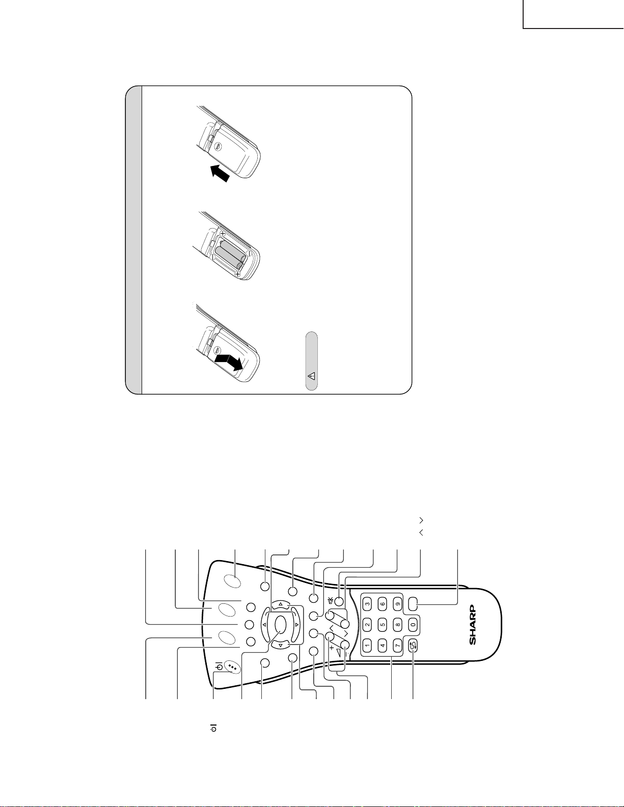
Installing Batteries in the Remote Control
Before using the LCD TV set for the first time, install the two R-03 (“AAA” size, UM/SUM-4) batteries supplied
in the remote control. When the batteries become depleted and the remote control fails to operate, replace
the batteries with new R-03 (“AAA” size, UM/SUM-4) batteries.
1
Open the battery cover.
2
Insert two R-03 (“AAA” size,
UM/SUM-4) batteries.
3
Replace the battery cover.
Ë Position the positive and
negative ends of the
batteries as indicated in
the compartment.
Caution!
Precautions regarding batteries
Ë Improper use of batteries can result in a leakage of chemicals and/or explosion. Be sure to follow the
instructions below.
• Place batteries with their terminals corresponding to the (+) and (–) indications.
• Different types of batteries have different characteristics. Do not mix batteries of different types.
• Do not mix old and new batteries. Mixing old and new batteries can shorten the life of new batteries and/
or cause old batteries to leak chemicals.
• Remove batteries as soon as they are depleted. Chemicals that leak from batteries can cause a rash. If
chemical leakage is found, wipe it off with a cloth.
• The batteries supplied with the product may have a shorter life expectancy due to storage conditions.
• If the remote control is not to be used for an extended period of time, remove the batteries from the
remote control.
Ë Engaging the lower
claw with the remote
control, close the
cover.
Ë Slide the cover while
pressing the ( ) part.
|
LC-20E1E
5
Page 6
LC-20E1E
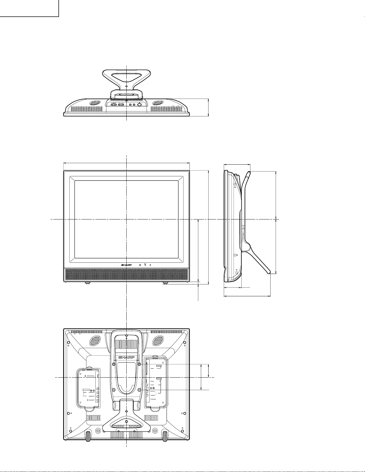
DIMENSIONS
MENU
TV/VIDEO
CH
Unit: mm
68
493
244
5
103
440
214 187
68
182
AUDIO OUT
100
L
R
AV-IN 1
RGB
AV-IN 1
S-VIDEO
VIDEO
L
AUDIO
R
POWER
INPUT
DC13V
51.5
100
6
Page 7
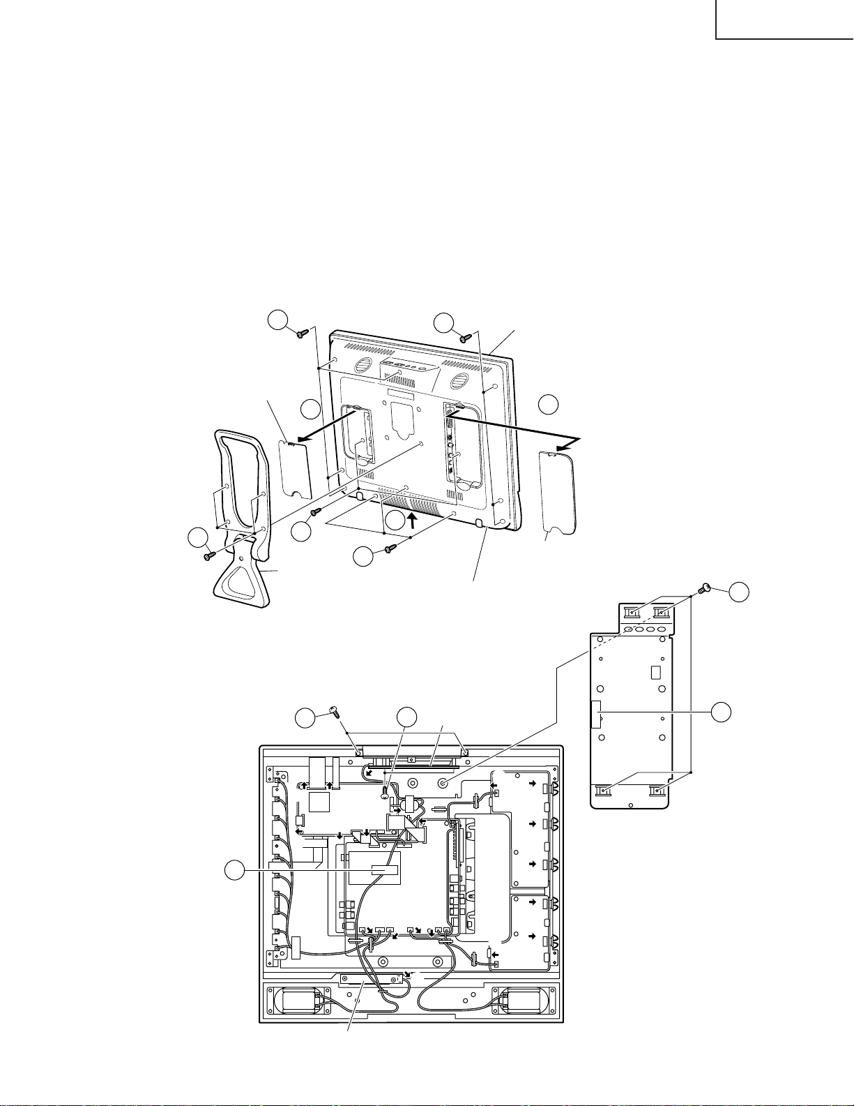
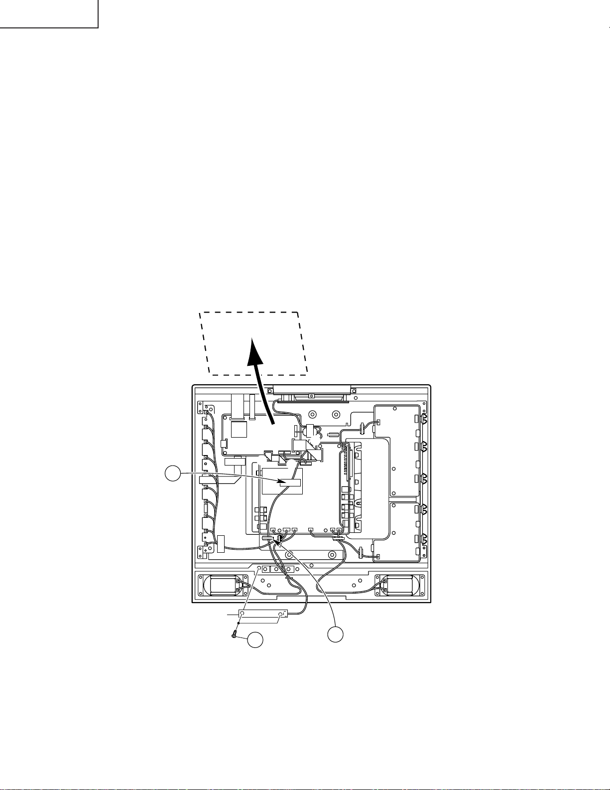
REMOVING OF MAJOR PARTS
P6705
SC1202
P4004
SC1203
P6706
SC2001
P1903
SC1602
P3601
Main PWB
P3604
1. Remove the table stand fixing screws (4 pcs.).
2. Remove the two terminal covers.
3. Remove the terminal section fixing screws (2 pcs.).
4. Remove the cabinet B fixing screws (10 pcs.).
5. Remove the cabinet B after opening from the direction of an arrow.
6. Peel off the tape. Remove the reinforcement angle fixing screws (4 pcs.).
7. Remove the top cover fixing screws (2 pcs.).
8. Remove the operation PWB fixing screws (2 pcs.).
9. Peel off the tape.
10. Detach the connector from each PWB.
LC-20E1E
1
4
Terminal
Cover (S)
3
Stand
7
4
2
Cabinet A
2
5
4
Cabinet B
8
Operation PWB
Terminal
Cover (L)
6
Reinforcement
Angle
6
Tape
9
Tape
0
SC1203
SC1203
0
SC1202
SC1201SC1202
Main PWB
Main PWB
0
SC2002
P3601
P3601
R/C, LED PWB
P4004
P4004
P2003
0
P3702
SC2001
SC2001
SC1602
Tuner PWB
0
0
P1903
P1903SC1602
0
0
SC3100
0
P3603P3301P3302P3602
P3604
P3604
7
0
P6705
P6705
0
P6706
P6706
Inverter-A
PWB
0
0
0
Inverter-B
PWB
Page 8
LC-20E1E
11. Remove the inverter-A PWB fixing screws (2 pcs.).
12. Remove the inverter-B PWB fixing screws (1 pc.).
13. Remove the main PWB fixing screws (3 pcs.).
14. Remove the 21-pin terminal fixing screw (2 pcs.).
15. Remove the tuner PWB fixing screws (3 pcs.) and detatch the chassis frame cover fixing hooks.
16. Remove the R/C, LED PWB fixing screws (2 pcs.).
Chassis Frame
13
Main PWB
Tuner PWB
11
12
Inverter-A
PWB
15
Inverter-B
PWB
15
14
Chassis
Frame Cover
16
15
R/C, LED PWB
8
Page 9
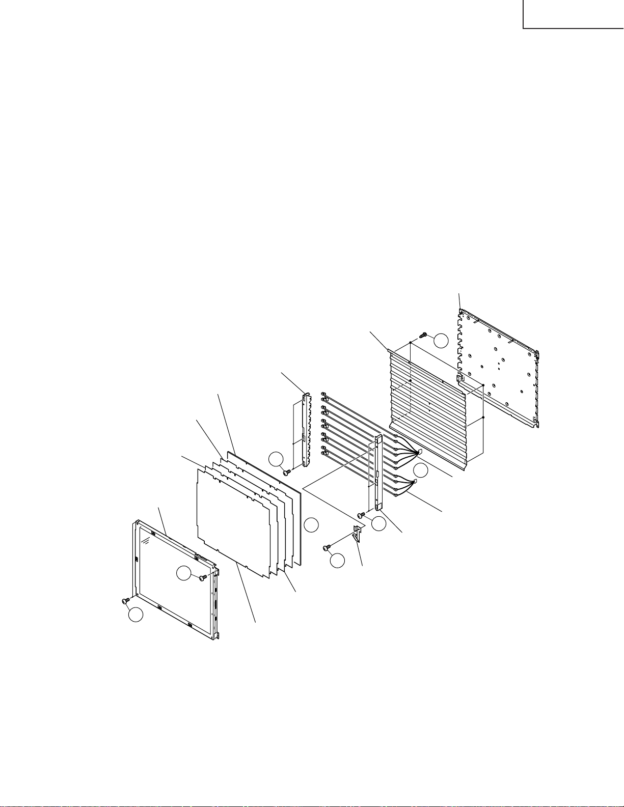
» Precautions in handling the LCD panels
1. Work in a clean room (with humidities below 50%).
2. Be sure to wear an anti-static armband.
3. Handle the panels on an electroconductive mat.
4. Be careful not to fall, shake and shock the panels.
17. Remove the LCD panel unit fixing screws (4 pcs.).
18. Remove the ITO earth spring fixing screw (1 pc.).
19. Remove the reflection/deflection, prism, diffusion, ITO sheets and diffusion panel.
20. Remove the lamp fixing holder fixing screws (6 pcs.).
21. Detach the lamp unit-A/B.
22. Remove the reflection mirror fixing screws. (6 pcs.).
Back shield Panel
(PSLDM4685CEFW)
LC-20E1E
Diffusion Panel
(PCOVU0107CEZZ)
ITO Sheet
(PSHEP0289CEZZ)
Prism Sheet
(PSHEP0287CEZZ)
20" LCD Panel Unit
17
17
Lamp Fixing Holder
(LHLDZ2176CEZZ)
20
19
Diffusion Sheet
(PSHEP0288CEZZ)
Reflection/Deflection Sheet
(PSHEP0286CEZZ)
Reflection Mirror
(PMiR-0296CEZZ)
20
18
ITO Earth Spring
(MSPRP1220CEFW)
22
21
Lamp Unit-A
(KLMP-A124CEZZ)
Lamp Unit-B
(KLMP-A125CEZZ)
Lamp Fixing Holder
(LHLDZ2176CEZZ)
9
Page 10
LC-20E1E
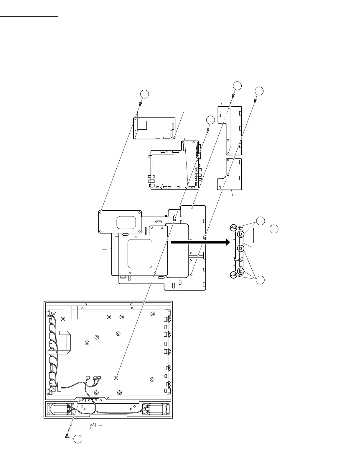
»Precautions at the time of the side B(back) service of main unit.
1. Remove only SC2001 of the FFC for connection between Main unit(SC2001) and Tuner unit(SC3100), and connect the extended cable (QCNW-A369WJZZ) for service.
2. Remove only P3702 of the FFC f or connection betw een Main unit(P3702) and Tuner unit(P1903), and connect the
extended cable (QCNW-A371WJZZ) for service.
3. Remove only SC2002 of the FFC for connection between Main unit(SC2002) and Tuner unit(SC1602), and connect the extended cable (QCNW-A370WJZZ) for service.
4. Remove the R/C, LED unit.
4-1. Peel off the tape.
4-2. Remove a lead from a wire holder.
4-3. Remove the R/C, LED unit fixing screws(2 pcs.).
5. Remove the main unit fixing screws(3 pcs.), a substrate is reversed.
4-1
Tape
Main PWB
(Side B)
SC1203
SC1203
Main PWB
Main PWB
SC1201SC1202SC1202
SC2002
3
P3601P3601
P4004P4004
P2003
P3702
SC2001SC2001
2
P1903SC1602 P1903SC1602
Tuner PWB
1
SC3100
P3603P3301P3302P3602
P3604P3604
Inverter-A
P6705
P6705
PWB
Inverter-B
PWB
P6706
P6706
R/C, LED PWB
4-3
10
4-2
Wire holder
Page 11

LC-20E1E
ADJUSTING PROCEDURE OF EACH SECTION
The best adjustment is made before shipping. If any position deviation is found or after part replace is performed,
adjust as follows.
Preparation for adjustments
Use the dedicated AC adaptor or stable DC power supply.
LC20E1E AC adaptor: UADP-0241CEPZ
DC power supply: 13V 5.4A
1.Adjusting procedure
• Checker adjustment
Power ON (Adjustment processing mode) → +B adjustment → Counter bias adjustment → TAMP (Contrast)
adjustment → White balance adjustment
2.Entering the adjustment processing mode
There are the following two methods.
• Setting the pin (81)(KEY4) or pin (82)(KEY5) of IC2001 (microprocessor) to GND, turn on the power.
• A “POWER” key is made on with pushing an “TV/VIDEO” and “MENU” keys at the same time.(K of the inspection
process mode is displayed by the upper left of the image plane .) → Next, “CH (Ù)” and “V OL (–)” keys are pushed
at the same time.(It becomes the image plane of the adjustment process mode.).....When it is canceled, it is made
to turn it off.(Even off in the “MAIN POWER” key, off with R/C are good.)
3.Key operation in the adjustment process mode
• The receiving channel UP/DOWN is performed with the “CH (ù)/(Ù)” keys.
One push ... The UP/DOWN tuning is performed per channel.
Continuous push ... The UP/DOWN search is performed until a next receivable station is found.
• V arious adjustments
The adjustment is performed for each item by the “MENU”, “Menu cursor”, “CH (ù)/(Ù)” or “VOL (+)/(–)” keys
(LCD TV set and remote control).
• Adjustment item is chosen with the Menu cursor upward/downward keys.
• The adjustment item makes a toggle operation with the “MENU” key input. (Next item)
If the “MENU” key is input while the bottom item is selected, it moves to the top item on the next page.
• Press the auto preset button on the remote controller in the adjustment process mode, and the top item of the
next page will show up regardless of which item appears now.
Page 1 → Page 2 → ... → Page 24 → Page 1
• Press the manual memory button on the remote controller in the adjustment process mode, and the top item of
the same page will show up.
• UP/DOWN of each adjustment vale selected is performed with the VOL (+)/(–) keys input.
• For P16 – 17, the unit enters the register select mode with the VOL (+)/(–) keys input while NTSC/PAL is selected,
and the cursor moves to the address 01.
• The cursor moves up or down with the “CH (ù)/(Ù)” keys and mo ves left or right with the VOL (+)/(–) keys, and a
decision is made with the 12 key.
When the decision is made, the cursor moves to the adjustment v alue selected, and UP/DOWN of each adjustment
value selected by the “VOL (+)/(–)” keys input is performed.
0 ↔ 1 ↔ ... ↔ 9 ↔ A ↔ ... ↔ F ↔ 0 ↔ ...
Decide with the 12 key and return to the address select. Move to the next item with the “MENU” key.
During address select, the cursor movement by the “VOL (+)/(–)” keys input is as follows:
Example: 01 ↔ 02 ↔ 03 ↔ 01 ↔ ...
The cursor movement by the “CH (ù)/(Ù)” keys input is as follows:
Example: 02 ↔ 05 ↔ ... ↔ F6 ↔ 02 ↔ ...
11
Page 12
LC-20E1E
4.Initialization
When the microprocessor (IC2001) or the EEPROM (IC2004) has been replaced or when the EEPROM has been
initialized, readjust the each adjustments.
4-1. Connect the pins (81) and (82) of IC2001 (microprocessor) to GND, and turn on the power.
4-2. Select the model name to (E1E).
4-3. Select the inch size (20).
4-4. L ED changes green from red after setting finish and about 15 seconds, initialization is completed, and it
becomes adjustment mode.
5.Adjustment
5-1. +B adjustment...Page 1 +B-ADJ
Adjust the voltage of the pin (13) of P2002 to 5.00 ±0.02V.
Note: Since 5.0V is a reference voltage of all power voltage, adjust it precisely.
5-2. Counter-bias adjustment
Vary the "COM BIAS" setting on Page 2 of the adjustment process mode so that the contrast be sharpest
(black looks most sinking).
5-3. TAMP adjustment
1) Receive the upper left of 75% white half colour bar signal.
2) See if the “Y” reading on page 2 of the adjusment process mode is somewhere following. If not, make the
“PAL TAMP” adjustment to get the “Y” reading in the range of BB thru CA.
3) If the adjustment of “PAL TAMP” is executed, write its adjustment value to the “SECAM TAMP” manually.
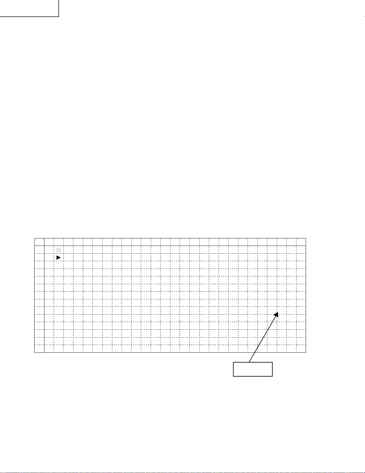
(Screen of the page 2 of the adjustment processing menu OSD)
0 1 2 3 4 5 6 7 8 9 10 11 12 13 14 15 16 17 18 19 20 21 22 23 24 25 26
0
1
2
3
4
5
6
7
8
9
10
11
12
13
2
COM B I AS 9 0
PAL TAMP 21
SECAM TAMP 21
RCU TOF F
GCU T OF F
BCU TOF F
G3 B3 R3 00 00 00
G1 B4 Y 0 0 00 B5
TAMP H
TAMP L
Y Data
(White 75%)
—
5
0
— 3
CA
BB
5-4. White balance adjustment
Adjust “RCUTOFF” and “BCUTOFF” on the page 2 of the adjustment processing so as to obtain the colour
of the same level as the standard set.
Note: For the adjustment processing of “RCUTOFF” and “BCUTOFF”, adjust them in the indication value
range of ... –9, –7, ... –1, +1, ... +7, +9.
When it becomes even-numbered value, side favor noise sometimes occurs in the monochrome signal of
the specific gradation.
12
Page 13
LC-20E1E
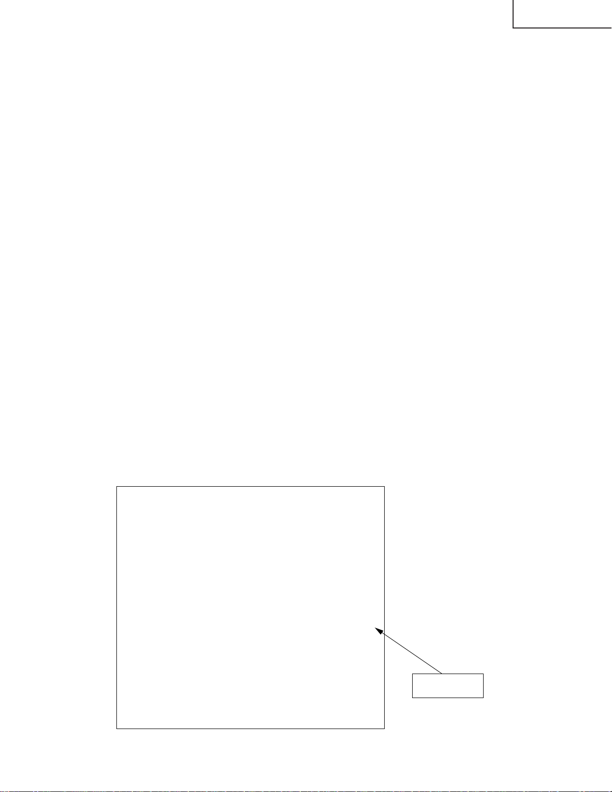
1
+B—A D J 160
M O D E L E1E
V E R 1 . 0 0 0
Reset 0
Afterwards, perform the operation check to confirm that the lamp error detection does not function.
Page 1 of the adjustment process
INCH SIZE 20
NTSC PWM FREQ 0C0
PAL PWM FREQ 0BD
NTSC PWM DUTY 0
PAL PWM DUTY 0
T V GAIN OFF
ERROR N O RESET 5
PUBLIC MODE OFF
E1E
6. Factory Setting
6-1. Perform a factory setting after completing all adjustments.
6-2. A “POWER” keys is made on with pushing an “TV/VIDEO” and “MENU” keys at the same time.
6-3. “K” of the inspection process mode is displayed on the screen upper left.
6-4. CH (ù) and VOL (+) keys are pushed about 2 seconds at the same time.
6-5. Release keys, if “E” is displayed on the screen upper left and “COMPLETE” is displayed on the bottom of it.
6-6. After a while, a power will be in a standby mode and a setup will be finished.
Note: “First installation” serves on “Deutsch”.
7. Lamp error detection
7-1. Functional description
This LCD colour television has a function (lamp error detection) to be turned OFF automatically for safety
when the lamp or lamp circuit is abnormal.
If the lamp or lamp circuit is abnormal, or some other errors happen, and the lamp error detection is executed,
the followings occur.
1 The main unit of television is turned OFF 5 seconds after it is turned ON. (The power LED on the front side
of TV turns from green to red.)
2 If the situation 1 happens 5 times sequentially, television can not be turned ON. (The power LED remains
red.)
7-2. Countermeasures
7-2-1.Check when turning OFF the lamp error detection
When television is turned OFF by the lamp error detection mentioned above, it enters the adjustment
process with the power LED red. Entering the adjustment process turns OFF the error detection and turns
ON TV.
This enables the operation check to detect errors in the lamp or lamp circuit.
Check whether "ERROR NO RESET" on line 9, page 1 of the adjustment process is 1 or more. If it is 1 or
more, it indicates the lamp error detection was executed.
7-2-2.Resetting of the lamp error count
After confirming that the lamp or lamp circuit is normal, reset the lamp error count. Select "ERROR NO
RESET" on line 9, page 1 of the adjustment process and set the number to 0 using the volume button.
13
Page 14
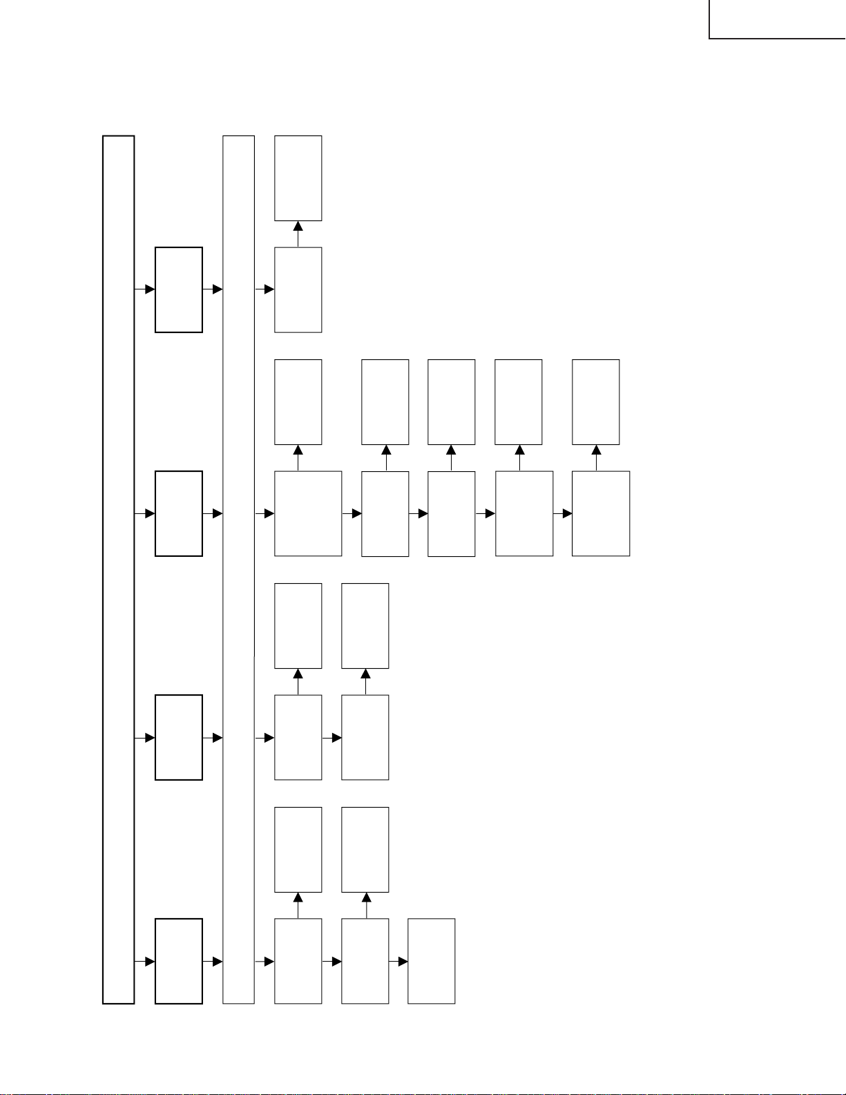
LC-20E1E
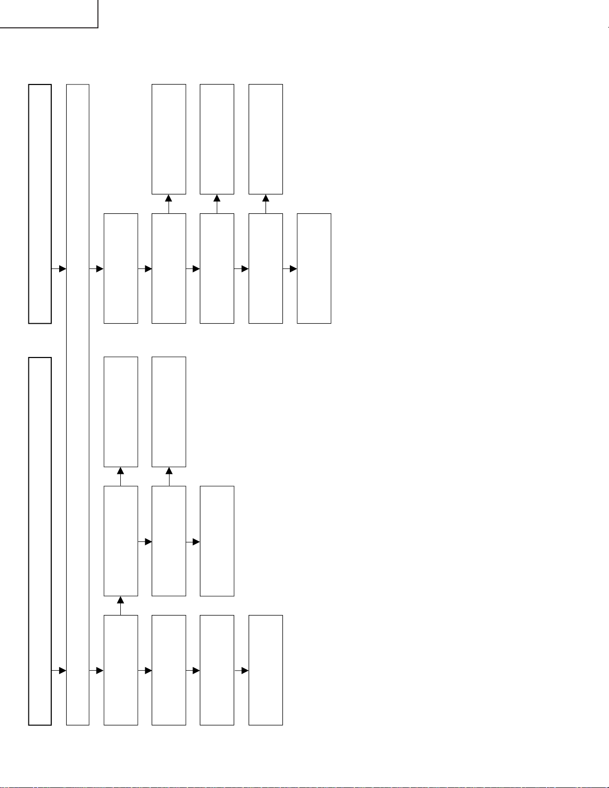
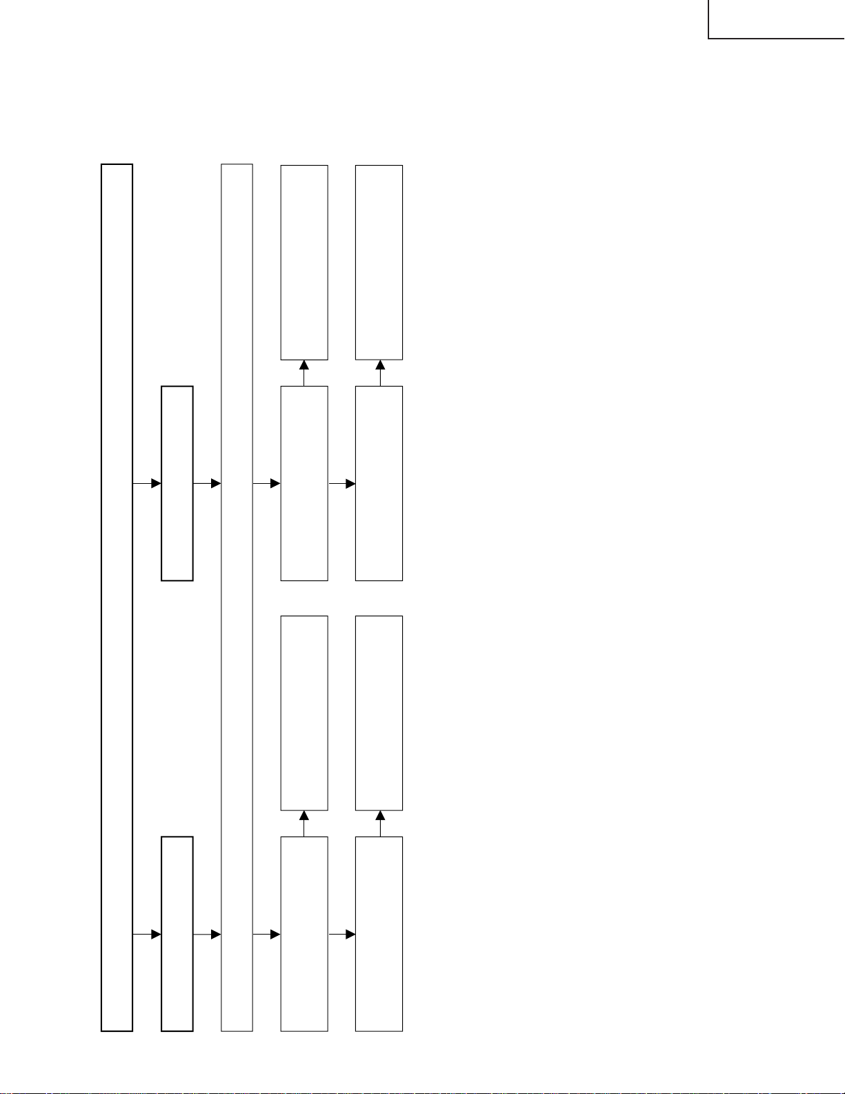
No picture and No sound
Check all the settings microprocessor’s adjust process menu.
Do F1 and F2 function?
Are T3701’s secondary
outputs, +31V, +22V, +9V,
+5V and -8V normal?
Remove F1 and F2 and
check the load side.
Is there short-circuiting?
Is there short-circuiting of
T3701 primary side periphery,
Q3700, Q3701 and S4701.
Replace F1 and F2.
Check S4701 and
connection cable.
Is T3701’s primary oscillator
waveform normal?
Check T3701’s secondary
load.
Yes Yes
No
No
No No
No
Yes
Check J3702 periahery and
connection cable.
Replace F6700~F6704.
Is the pin (34) of IC1201 in
the "H" state?
Is the output of Q3650 in the
"
L
"
state?
Yes
Yes
No
No
No
Yes
Yes
Check the OFL1 line, IC1201
and their peripheral parts.
Check the OFL line, Q3650
and their peripheral parts.
Check T6700~T6709,
Q6700~Q6714 and
connection cable.
Back light lamp failure to light up
Is the primary side of
T6700 ~T6709 periphery
short-circuiting?
Replace the back light lamp
with new one and check
again.
TROUBLE SHOOTING TABLE
14
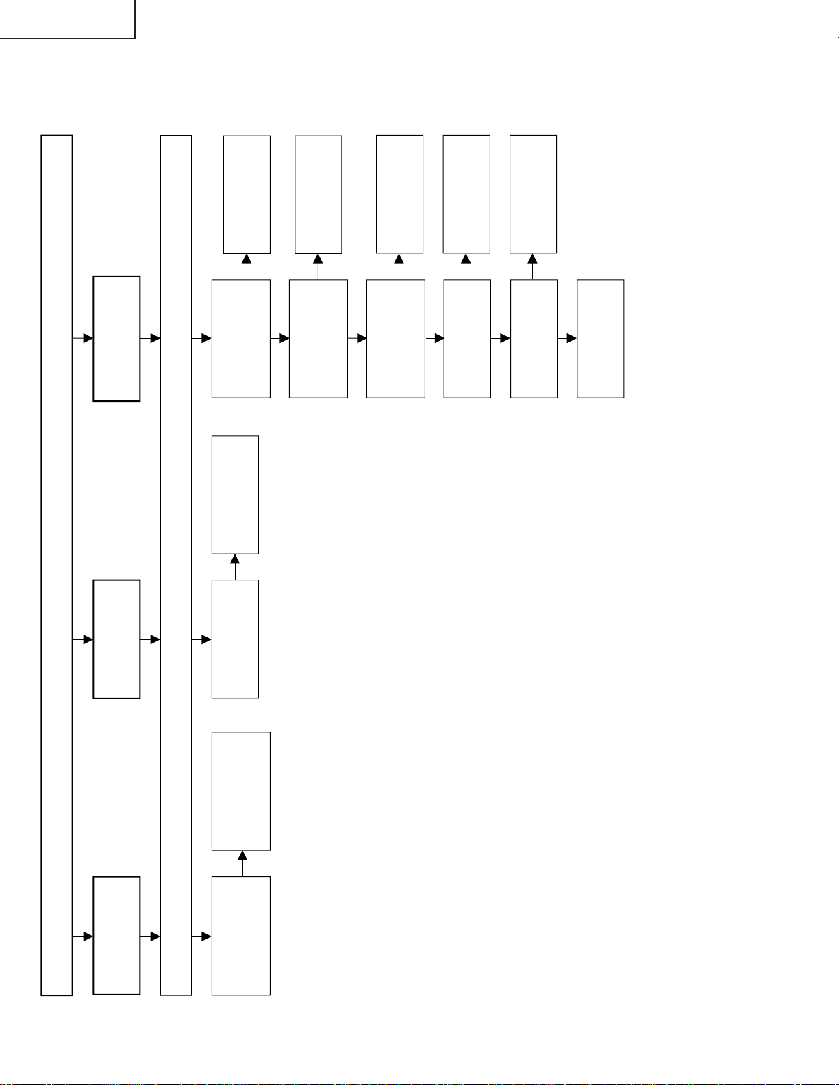
Page 15
No picture (1/3)
Check all the settings microprocessor
’s adjust process menu.
Is in/output of
IC801 normal?
Is in/output of
IC1201 normal?
Check IC801
and its
peripheral parts.
Check IC1201
and its
peripheral parts.
Check IC402
and its
peripheral parts.
Check IC801,
AV1 line and its
peripheral parts.
Check LCD
panel voltages
and waveform.
Yes
Yes
No
No
No picture
at all
Is in/output of
IC402 normal?
Is input at pin
(73) of IC801
normal?
Yes
No
No
No TV and
S-Video
output
Is voltages at
pins (6), (7) and
(18) tuner
normal?
Is output at pin
(13) of tuner
normal?
Check the
power line.
Check tuner
and its
peripheral parts.
Is input at pin
(3) of tuner
normal?
Is the pins (2)
and (4) of IC402
at "H" and "L"
state?
Yes
Yes
No
No
No
No
No
Yes
No TV output
Is the pins (65)
and (66) of
IC2001 at "H"
and "L" state?
Yes
Check the its
line.
Check the its
line.
Check IC402
and its
peripheral parts.
Is input at pin
(75) of IC801
normal?
Check V1 IN
line and its
peripheral parts.
No
No VIDEO 2
output
TROUBLE SHOOTING TABLE (Continued)
LC-20E1E
15
Page 16
LC-20E1E
No picture (2/3)
Check all the settings microprocessor
’s adjust process menu.
Is input at pin
(74) of IC801
normal?
Check the AV2
line and its
peripheral parts.
No
No VIDEO 1
output
Check the SY-line,
SC-line and their
peripheral parts.
Is input at pin (1)
of IC402 and pin
(71) of IC801
normal?
No
No S-VIDEO
output
Check IC1203
and its
peripheral parts.
No
No
Yes
Yes
Yes
No TELETEXT
output
Yes
Is input at pins (2),
(5), (11), and (14)
of IC1203 normal?
Is input at pins (3),
(4) and (5) of
SC1602 normal?
Is output at pins (1)
and (7) of IC1619 and
pin (1) of IC1620
normal?
No
Check connection
cable
Check the R, G
and B line.
No
Check IC1619,
IC1620 and their
peripheral parts.
Is output at pins
(57)~(59) of IC1601
normal?
No
Yes
Check V2VO line
and its peripheral
parts.
Is input at pin (21) of
IC1601 normal?
Check IC1601 and its
peripheral parts.
TROUBLE SHOOTING TABLE (Continued)
16
Page 17
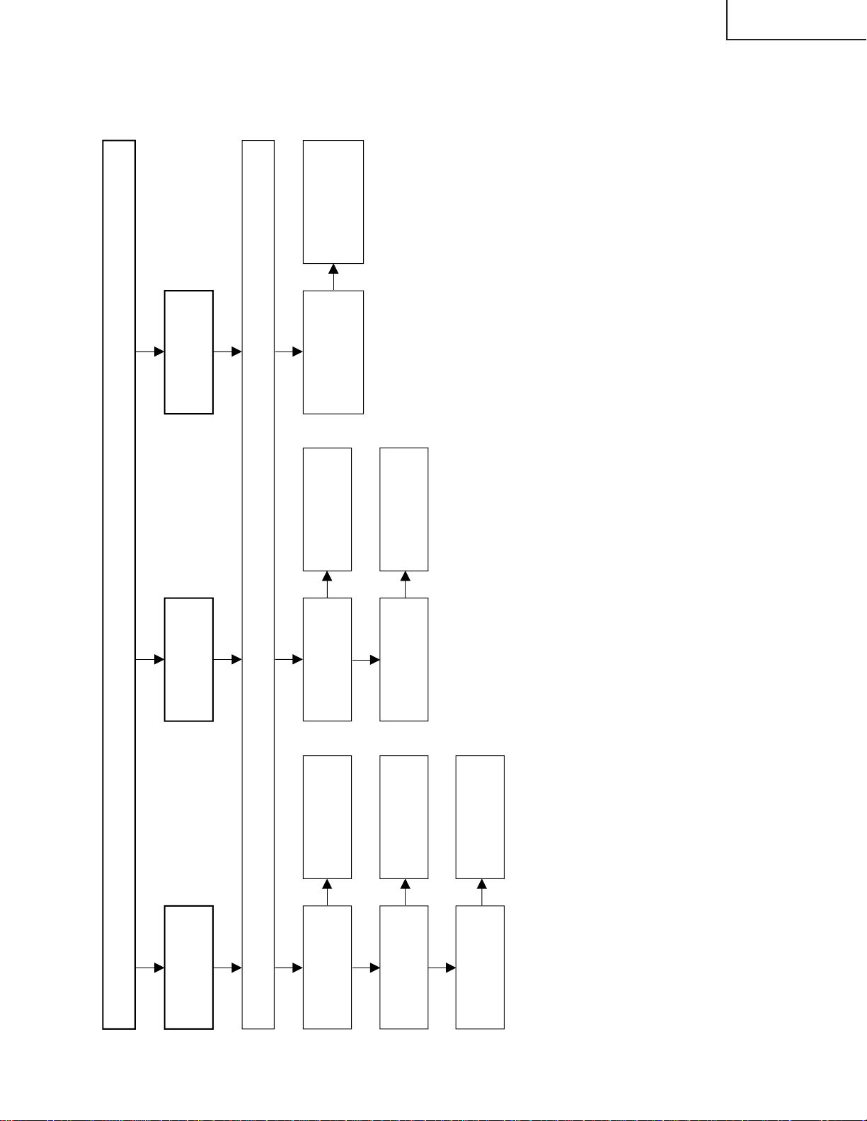
TROUBLE SHOOTING TABLE (Continued)
No picture (3/3)
Check all the settings microprocessor
’s adjust process menu.
Is output of
R0~R7
normal?
Is output of
G0~G7
normal?
Is output of
B0~B7
normal?
Yes
Yes
No
No
No
Colour is
unusual
Is in/output of
SPIO and
SPOI normal?
No
No picture
image
inversion
No
Gradation
defect
Is output of U/D
normal?
Yes
No
Check R1202 and
its peripheral parts.
Check R1209 and
its peripheral parts.
Check IC1206,
IC1207, Q1201 and
their peripheral
Check R1203 and
its peripheral parts.
Check R1204 and
its peripheral parts.
Is output V0, V7, V17,
V21, V32, V64, V122,
V176, V235 and
V255 normal?
Check IC1106,
IC1107, IC1108,
IC1114, IC1115 and
their peripheral parts.
LC-20E1E
17
Page 18
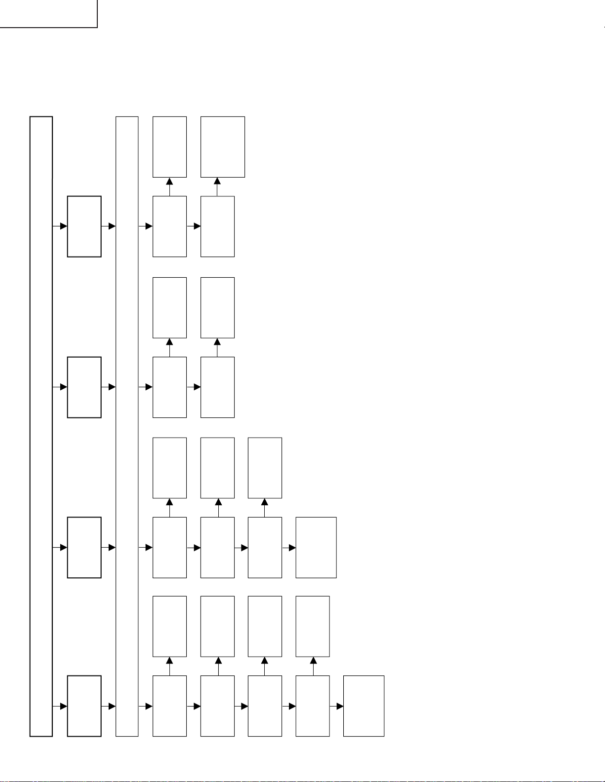
LC-20E1E
No sound (1/2)
Check all the settins microprocessor
’s adjust process menu.
Is the pin (53) of
IC2001 in the
"L" state?
Is output at pins
(27) and (28) of
IC1901 normal?
Is output at pins
(1) and (7) of
IC1903 normal?
Yes
Yes
No
No
No
No sound
from front
speakers
Yes
Muting effect is
on. Check the
FSMUTE line.
Check IC1901
and its
peripheral parts.
Check IC1903
and its
peripheral parts.
Is the pin (52) of
IC2001 in the
"L" state?
Is output at pins
(24) and (25) of
IC1901 normal?
Is output at pins
(1) and (7) of
IC304 normal?
Yes
Yes
No
No
No
Yes
Muting effect is
on. Check the
HP_MUTE line.
Check IC1901
and its
peripheral parts.
Check IC304
and its
peripheral parts.
No sound
from
headphone
TV sound
failure
Is output at pins
(33) and (34) of
IC1901 normal?
Is output at pins
(1) and (7) of
IC3500 normal?
Check IC1901
and its
peripheral parts.
Check IC3500
and its
peripheral parts.
Yes
No
No
No
No sound
from output
line
Check the tuner
and its
peripheral parts.
Yes
No
Is output at pin
(11) of Tuner
normal?
Is input at pins
(67) and (69)
of IC1901.
Check IC1901
and its
peripheral
parts.
Check
Headphone Jack
and connection
cable.
No
Is output at pins
(8) and (12) of
IC3305 normal?
Check IC3305
and its
peripheral parts.
Check front
speaker and
connection
cable.
Yes
TROUBLE SHOOTING TABLE (Continued)
18
Page 19
TROUBLE SHOOTING TABLE (Continued)
No sound (2/2)
Check all the settings microprocessor
’s adjust process menu.
Yes
No
No
No sound from SCART
No
SCART sound failure
Yes
No
Check IC1901 and its
peripheral parts.
Is output at pins (36) and (37) of
IC1901 normal?
Check IC1902 and its
peripheral parts.
Is output at pins (1) and (7) of
IC1902 normal?
Check their lines and their
peripheral parts.
Is input at pins (53) and (54) of
IC1901 normal?
Check IC1901 and its
peripheral parts.
Is output at pins (27) and (28) of
IC1901 normal?
LC-20E1E
19
Page 20
LC-20E1E
CHASSIS LAYOUT
H
G
F
E
MAIN Unit
OPERATION Unit
TUNER Unit
D
C
B
R/C, LED Unit
A
87109654321
20
Page 21
INVERTER-A Unit
LC-20E1E
INVERTER-B Unit
21
1716 1918151413121110
Page 22
LC-20E1E
A
L
/
S
N
R
_
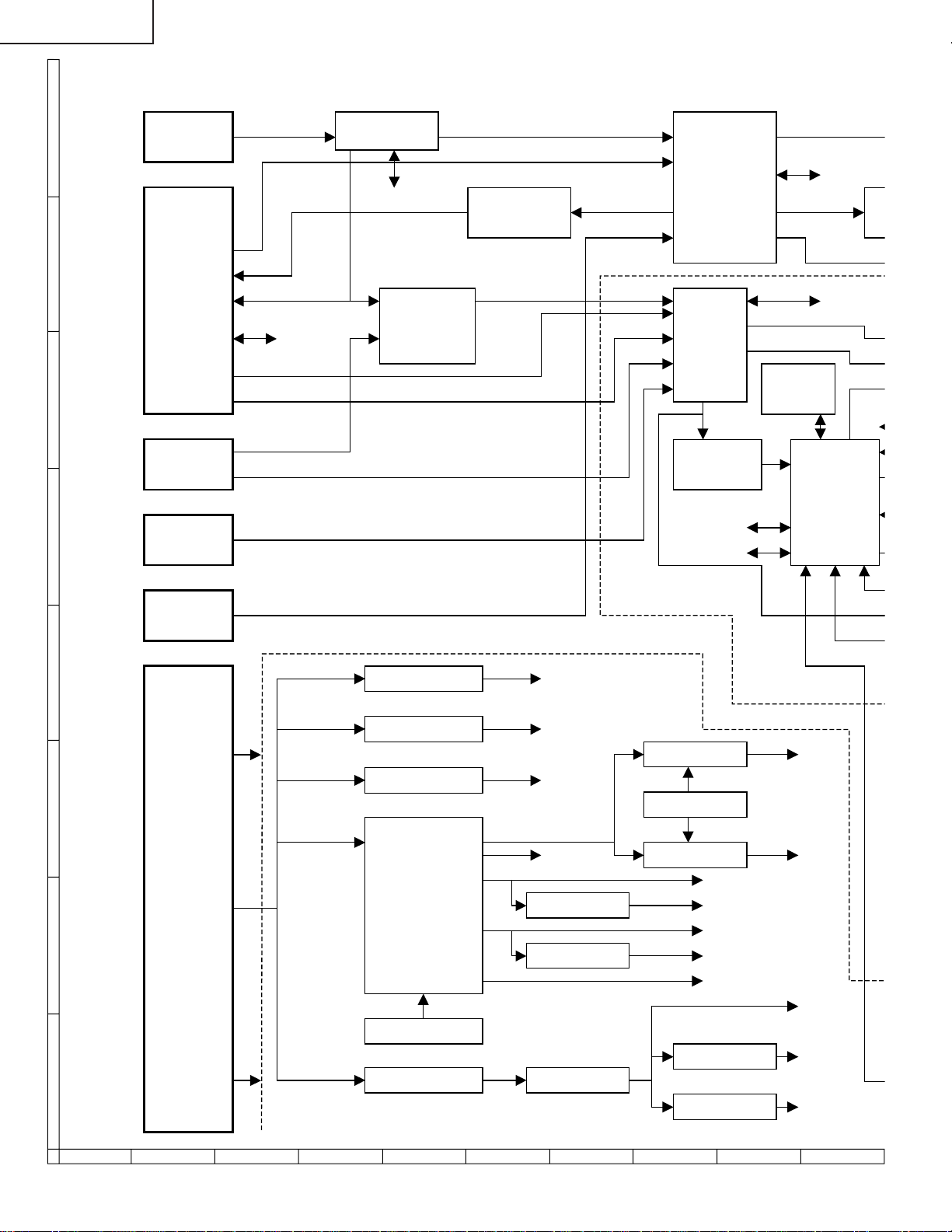
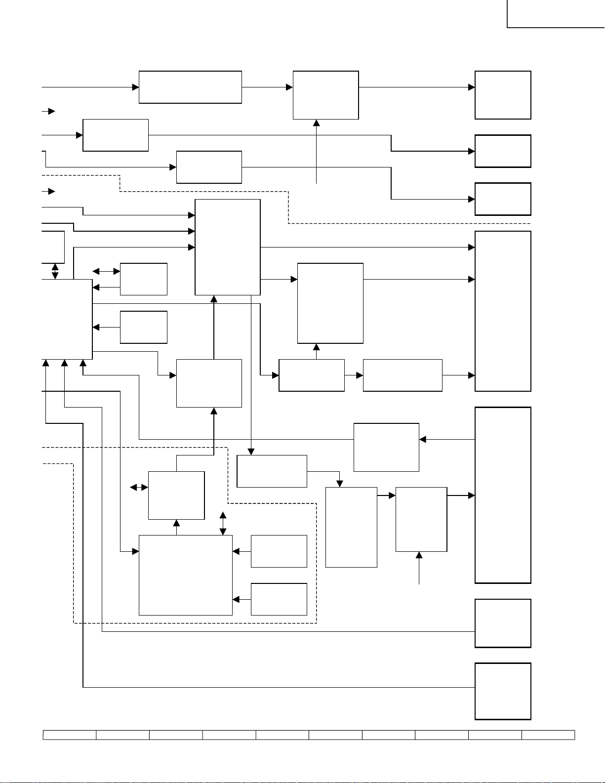
BLOCK DIAGRAM
V1.SY
TUNER
TV_V
SIF1/2
AI_L/R
2
C
I
SC_L/R
TV/AV
SELECTOR
IC402
AUDIO AMP
IC1902
ANA_IN1+/2+
SC2_IN_L/R
SC1_OUT_L/R
SC1_IN_L/R
V2_V R/G/B_IN
V1. SC
V1IN
DACM_L/R
MSP
IC1901 DACA_L/R
VPC
CSYNC
2
PROM
E
IC2030
SPI
IC801
V2VO
SYNC SEP
IC401
2
C
I
UART
I2C
SC2_OUT_
2
I
C
CO
2
C
I
MICON
IC2001
Y
L
J5002
J5001
ANTENNA
SCART
(AV1)
AUDIO IN
AUDIO OUT
VIDEO OUT
SDA/RXD
SCL/TXD
VIDEO IN
R/G/B_ST
S
INPUT
VIDEO
(AV2)
INPUT
AUDIO
(AV2)
INPUT
V1.L/R
2
I
C/UART
H
SC3903
G
F
SC5001
E
D
C
B
A
J3702
DC13V
INPUT
PAVCC
SIGVCC
INVVCC
REG
REG
REG
IC1208
IC751
IC703
DC/DC
CONVERTER
T3701
PWM
IC3701
Q3700
+13V
+3.3V
+5V
+5V
+31V
—20V
REG
REG
Q3706
IC1610
IC752
Q3704
IC3702
Q3707
REG
REG
+9V
+8V
+5V
+3.3V
—8V
IC1606
IC1613
+22V
+31V
+5V
+3.3V
+2.5V
22
87109654321
Page 23
LC-20E1E
CM_L/R
2
C
I
CA_L/R
SC2_OUT_L/R
I2C
OM
030
I
MICON
IC2001
AUDIO AMP
IC304
Y/UV
SYNC SIGNAL
CONTROL SIGNAL
2
C
I
2
E
PROM
IC2004
RESET
RESET
IC2002
L_ERR
AUDIO ACTIVE FILTER
IC1903
AUDIO AMP
IC3500
LCD
CONTROLLER
IC1201
OFL1
OSD R/G/B
R/G/B
OSD/TEXT
SELECTOR
IC1203
TEXT R/G/B
L/R_IN AUDIO
POWER AMP
IC3305
A0_L/R
PAVCC(+13V)
REV
GRADATION
POWER
MPCLK
MPDA
DAC2CS
IC1102~1108
IC1110
IC1112~1115
DAC1CS
DAC
IC1101 1111
FLSP/FRSP
HL/R
R0~7 G0~7 B0~7
V0 V7 V17 V21 V32 V64
V112 V176 V235 V255
VGLCOM
COMMON DRIVE
IC1109
VCOM
CSCOM
SPEAKER
HEADPHONE
JACK
AUDIO OUT
LCD
PANEL
P3301
P3302
J5003
J3902
J3903
SC1201
SC1202
SC1203
P3601
+22V
+31V
+5V
+3.3V
+2.5V
UART
CVBS
TEXT
R/G/B AMP
IC1619 1620
R/G/B
TELETEXT
CPU
IC1601
OFL REVERSE
Q3650
2
C
I
SRAM 2M
FLASH 4M
IC1603
IC1602
OFL
L_ERR
DC/AC
INVERTER
DRIVE
Q6700
~6714
LAMP ERROR
DETECTOR
Q3600 3601
DC/AC
TRANS
INVVCC(+13V)
T6700
~6709
HV1/2/3
BACK
LIGHT
LAMP
P4001
KEY
P4004
REMOTE
CONTROL
RECEIVER
23
1716 1918151413121110
Page 24

LC-20E1E
OVERALL WIRING DIAGRAM
H
G
F
E
D
C
B
A
87109654321
24
Page 25

LC-20E1E
25
1716 1918151413121110
Page 26

LC-20E1E
DESCRIPTION OF SCHEMATIC DIAGRAM
VOLTAGE MEASUREMENT CONDITION:
1. The voltages at test points are measured on
exclusive AC adaptor and the stble supply voltage
of AC 120V. Signals are fed by a color bar signal
generator for servicing purpose and the above
voltages are measured with a 20k ohm/V tester.
INDICATION OF RESISTOR & CAPACITOR:
RESISTOR
1. The unit of resistance “Ω” is omitted.
(K=kΩ=1000 Ω, M=MΩ).
2. All resistors are ± 5%, unless otherwise noted.
(J= ± 5%, F= ± 1%, D= ± 0.5%)
3. All resistors are 1/16W, unless otherwise noted.
4. All resistors are Carbon type, unless otherwise
noted.
C
: Solid
S : Oxide Film T : Special
N : Metal Coating
CAPACITOR
1. All capacitors are µF, unless otherwise noted.
(P=pF=µµF).
2. All capacitors are 50V, unless otherwise noted.
3. All capacitors are Ceramic type, unless otherwise
noted.
(ML): Mylar (TA): Tantalum
(PF): Polypro Film (ST): Styrol
W
: Cement
CAUTION:
This circuit diagram is original one, therefore there may be a
slight difference from yours.
IMPORTANT SAFETY NOTICE:
PARTS MARKED WITH “å” ( ) ARE
IMPORTANT FOR MAINTAINING THE SAFETY OF
THE SET. BE SURE TO REPLACE THESE PARTS
WITH SPECIFIED ONES FOR MAINTAINING THE
SAFETY AND PERFORMANCE OF THE SET.
26
Page 27

SCHEMATIC DIAGRAM
Ë
R/C, LED and OPERATION Unit
H
G
F
R/C, LED
LC-20E1E
E
OPERATION
D
C
B
A
654321
27
Page 28

LC-20E1E
Ë
MAIN Unit-1/6
H
G
F
E
D
C
B
A
87109654321
28
Page 29

LC-20E1E
29
1716 1918151413121110
Page 30

LC-20E1E
Ë
MAIN Unit-2/6
H
G
F
E
D
C
B
A
87109654321
30
Page 31

LC-20E1E
31
1716 1918151413121110
Page 32

LC-20E1E
Ë
MAIN Unit-3/6
H
G
F
E
D
C
B
A
87109654321
32
Page 33

LC-20E1E
33
1716 1918151413121110
Page 34

LC-20E1E
Ë
MAIN Unit-4/6
H
G
F
E
D
C
B
A
87109654321
34
Page 35

LC-20E1E
35
1716 1918151413121110
Page 36

LC-20E1E
Ë
MAIN Unit-5/6
H
G
F
E
D
C
B
A
87109654321
36
Page 37

LC-20E1E
37
1716 1918151413121110
Page 38

LC-20E1E
Ë
MAIN Unit-6/6
H
G
F
E
D
C
B
A
87109654321
38
Page 39

LC-20E1E
39
1716 1918151413121110
Page 40

LC-20E1E
Ë
TUNER Unit-1/4
H
G
F
E
D
C
B
A
87109654321
40
Page 41

LC-20E1E
41
1716 1918151413121110
Page 42

LC-20E1E
Ë
TUNER Unit-2/4
H
G
F
E
D
C
B
A
87109654321
42
Page 43

LC-20E1E
43
1716 1918151413121110
Page 44

LC-20E1E
Ë
TUNER Unit-3/4
H
G
F
E
D
C
B
A
87109654321
44
Page 45

LC-20E1E
45
1716 1918151413121110
Page 46

LC-20E1E
Ë
TUNER Unit-4/4
H
G
F
E
D
C
B
A
87109654321
46
Page 47

LC-20E1E
47
1716 1918151413121110
Page 48

LC-20E1E
Ë
INVERTER-A Unit
H
G
F
E
D
C
B
A
654321
48
Page 49

LC-20E1E
Ë
INVERTER-B Unit
H
G
F
E
D
C
B
A
654321
49
Page 50

LC-20E1E
PRINTED WIRING BOARD ASSEMBLIES
H
G
F
E
INVERTER-A Unit (Component Side)
D
C
B
A
INVERTER-B Unit (Component Side)
654321
50
Page 51

LC-20E1E
H
G
F
E
INVERTER-A Unit (Chip Parts Side)
D
C
B
A
INVERTER-B Unit (Chip Parts Side)
654321
51
Page 52

LC-20E1E
H
G
F
E
D
C
B
A
MAIN Unit (Side-A)
654321
52
Page 53

LC-20E1E
Z1
P2003
C3718
C3712
C3737
Q3702
C3714
L3703
FB3700
C3722
R3722
T3701
R3720
L3700
R3721
C3724
FB3705
R3709
R3711
C3707
C3708
D3705
R3710
C3703 C3701
R3708
C3705
R3707
R3761
R3760
R3728
C3719 C3716
D3701
C3706
R3727
R3714
R3715
R3712
C3709
R1142
R1166
R1167
R1168
C1105
R1178
R1179
R1177
R1034
R1027
R1029
R1028
C1130
C1156
C1137 C1136 R1185
R1195 R1194
R1186 C1138 C1139
C1129
C1118
C1126
R1155
R1156
R1157
IC1104
R1169
R1023
C1142 C1148 R1187
R1199 R1196
R1033
R1110
R1025
R1026
R1154
R1024
R1188 C1141 C1143
R1176
R1174
R1175
C1123
R1171
R1172
R1170
R1121
Q1102
R1123 Q1101
R1122
C1114 C1135 R1183
R1032
R1031
R1193 R1192
R1114
R1112
C1147
R1107
R1111
R1161
R1184 C1134 C1115
R1130 R1127 R1120
R1128 R1126
C1122
C1125
R1125
R1132 R1131
C1111 C1112 R 1117
R1191 R1190
IC1103
R1106
R1001
R1182 C1133 C1113
C1145
C1149
R1173
IC1116
C1103 C1150
C1120
R1109
R1002
R1104
R1102
C1108 C1109 R1116
R1134
R1198
R1158
R1162
R1163
C1104
R1108
R1160
R1150
R1151
R1152
R1189 R1153
R1133
R1115 C1107 C 1110
R1164
C910
R1013
R7001
C1209
L1202
R7024
R7020 R7021 R7022 R7023
SC1201
IC2007
R7019
C1210
C838
R808
L805
C834
C833
C826
C827
IC2006
C1241
C1214
C1242
R1202
R1203
IC1201
SC1202
R1204
FB1203
R1208
R1209
R1210
R1211
C842
C1240 R1264
C1243
C1219
R1217
C1203
R1218
R1223
R1232
R1214
R1233
IC1203
C1213 L1204
R1220
R1234
C1201
R1222
C1268 R1216
R1262
P3701
SC1203
C1267
R1226
R1258
R1257
R1201
C1223
R1263
C1266
C1217
C1216
C1229
C1228
IC1206
R854
C1204
IC803
R831
C843
R818
C821
C1231
C1226
C1225
C844
FL801
R840
R424
R423
C846
C849
C1206
C809 R422
C430
D1201
C847
FL401
R417
R1228 C1218
R1238
C850
C801
R425 R421
R403
Q401
R405
R404
Q421
C402
R427
C401
IC401
C835
R408
R406
R807
L804
C807
R806
R410 R409
C407 C405
C406
R402
R827
R401
C404
C908
L901
C756
C902
L902
C901
R2044
R2015 R2028
R2004
R2034
R2064
R2076
R2025
R2077
C2030
R2012
IC2030
R2043
TP2005
R2011
R2072
R2042
R2078
R2074
R2008
C2009
C1119
IC2001
SC2002
R2022
X2002
R2021
C1116
R2001
R2033
C2002
C2003
C2001
R2019
R2020
R2018
R2017
R2003
R2026
FB802
C2016
TP2009
R2030
R2052
L3704
C3727
IC751
C752
C753
R2027
C3735
R3752
D3709
R3737
R3739
R3738
R3751
P3702
C3733
R3750
C3741
IC3702
L3702
Q3706
C3732
R3735
R3736
R3741
R3749
SC2001
H
G
F
E
D
C
B
A
MAIN Unit (Chip Parts Side-A)
53
654321
Page 54

LC-20E1E
H
G
F
E
D
C
B
A
MAIN Unit (Side-B)
654321
54
Page 55

LC-20E1E
Z2
H
R775
R726
R777
C3717
R3730
D3704
R1129C1144
R1118R1014
C805
R804
R3729
R7011
R3700
C1102
IC7001
C3700
R3768
R3706
R3705
C3704
C3702
R3703
Q3700
Q3709
C1101
IC1102
D3706
FB3706
R3701
Q3710
R3766
R3704
IC1111
IC1101
R7015
R7016
R810
R813
C818
R816
C822
C839
FB3703FB3704R3723
FB3707D3707
R3702
D3700
FB3708R3724D3708C3725
Q3701
Q1108
C1153
R1145
D1107
D1101
Q1106
R1020C1151
C1157
R1003
R1005
R803R802R801
C806
R814
R811
R805
R826
R1221
R3742
R3743
R3745
R3746
R3734
R3733
C3730
Q3704
C3734
C3738
R3762
D1213D1203
C1232
IC752
Q1204
Q3707
R3740
C751
R1237
R751
Q751
C754
C1208
D2002
TP902
R2002
C903
R911
R2039
L1201
R912
R2035
R2038
IC2005
Q1201
FB902
IC901
IC2032
R2032
C2011
R2073
R2041
C2100R2006
R752R754R753
R830
Q752
Q2005Q2006
R910
D901
Q2004
R789
R790
D2001
R2024
C3728
Q753
C2017
R2031
R2009
C2006
IC2002
TP2003
R2007
C2010
R2010
C2019
R2013R2014
C2031
C2007
R2029
IC2004
R2005
IC2031
D902
FB903
FB901
R430
R419
L429
R418
C414
C408
C409
R415
R429
C429
C411
R428
Q820
R829C845
R1225
C1224
C848
R416
R1254
IC1207
C413
R414
C802
IC402
C410
Q420
C841
C810
R812
R837
C812
C814R426
C815
C816R420
C817
R815C840R817
C819
C820
R838R1256
R822R1255
G
F
R2023
R2036
R2037
E
R2068
D
C755
C403
C
B
C1234
C1230
D1208
R1251
R1240
R1239
D1209
R1248
IC1208
R1247
R1249
R1243
R1253
C1233FB1202
R1230R1231
R1252
Q1205
D1212
R1241D1204
D1205
R1246
D1210
D1211
R1250
R1245
D1206
C1227
Q1203
C3715
R3725
R3726
C3720C3721
Q1109
R1146
R852
R3732R3731
R1144
C1152R1140
R1143
R1141
R1147
IC1109
R1148
C1117C1121
R1119R1124
R1022
C1155
D1106
R1021
R1018
R1019
Q1107
D1105
R1010
D1110
R1016
R1017
Q1104
C832
C831
C830
R820
R821
R832
IC802
TP801
Q1103
TP802
R1006
R1007
R1008
D1108
R1009
D1109
R7018
R7003
R828
IC801
C823
C836
C837
C1205
R851
C1154
R1030
R1015
Q1105
R835R836
C804C803
X801
R833
R853
R3759
IC3701
R7002
R819
C3713
C3711
R3718
D3703
D3711
FB3701
C3740
FB801C813
D3702
C1131
IC111 2
C1132
IC111 3
C1146
IC111 0
C1124
IC1105
R7017
C1207
C1211
R7009
R7010
C1202
IC1202
C1212
R1236R1235
R3716
L1205L1203
FB1201
IC111 4
IC111 5
IC1108
IC1107
IC1106
R3719
R1259C1215
R1260R1212
Q3703
FB3709
R3713
R3717
A
MAIN Unit (Chip Parts Side-B)
55
654321
Page 56

LC-20E1E
P4001
D4010
D4009
D4008
SW4006
SW4004
R4012
R4011
SW4003
SW4002
R4005 R4006
SW4007
SW4008
H
G
F
E
D
C
B
A
(Component Side) (Chip Parts Side)
OPERATION Unit
(QPWBSB156WJN3)
654321
56
Page 57

LC-20E1E
H
G
F
E
D
C
B
A
TUNER Unit (Component Side)
654321
57
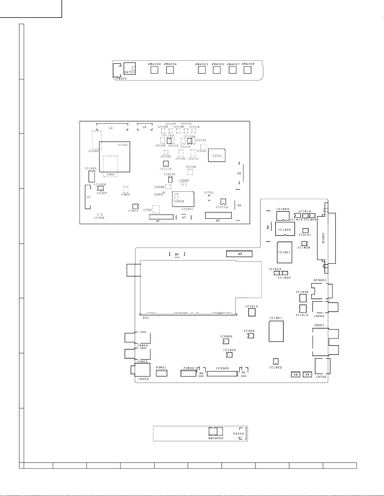
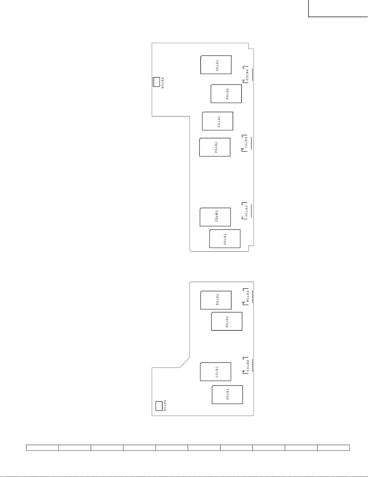
Page 58

LC-20E1E
Q3650
P3603P3604
H
R3650
R3357
G
C1907
C1926
R5708 R5709
R5712 R5713
R1942 R1941
R1928 R1929
C1915 C1916
F
R5705
C1661
R5711
D5701
C1660
E
R5710
R5714
R5707
D
R5706
R3968
C3900
C3957
R3969
C3956
C3901
C3954
C3955
Q3908
Q3909
R3966
R3992
R3993
R3967
C1662
R1610
IC1610
FB1608
C1609
R5716
IC1606
C1619
C1614
R1633
R1690
C1665
Q1633
C3902
R3962
R3964
D3912
C1657
R3996 R3995
R3998
R3997
R3994
Q3910
Q3911
C3961
C
C3962
R3963
C3903
C1626
R3401
R3459
R3494
D3911
D3902
D3908
B
A
D3493
R3461
R3492
R3457
D3404
R3458
R1678
R3456
D3403
R3460
R3491
R3455
D3412
R1665
R1664 R3965
IC1609
R1635
R1634
C3995
IC3101
R3433
FB1673
R1677
FB1674
C1653
IC1612
IC1614
IC1608
C1644
R1663
R1662
C1638
R1926
R1943
R1927
C1928
Q2201
R2204
R2205
L2201
C2209
IC1611
R1661
R1632
R1671
C1664
Q1632
C1656
R1658
FD1
R1657
C1631
C1668
C1667
C1666
C1633 C1634
R1642
FB1641
FB1640
C1650
C1625
R1643
IC1615
C1639 R1679
R1681
R1680
FD3
C1908
C1911
C1912
C1943
C1913
C1914
C1944
C1945
C1917
C1946
C1918
C1919
L1902
R2203
Q2200
R2201 C1922
R2208
R2202
C2201
R2206
R2207
C2202
C2203
L2200
L2202
L2204
C2208
C2207
L2205
R2211
L2206
R1636
C1636
C1637
IC1607
IC1616
R1683
R1695
R1631
R1670 R1698
Q1631
IC1620
C1655 C1663
R1638
R1639
R1637
C1635
IC1601
FB1672
IC1602
C1642
IC1603
C1646
C1641
P3703
R3370
C1941
R3371
R1936
R1934
C1961
R1925
R1945
IC1902
R1910
C1938
R1932
R1931
R1930
R1933
C1939
C1940
R1909
C1906
R1908
R1907
C1909
C1905
IC1901
R1913
C1920
C1921
C1923
C1924
R2218
R2217
Q2203
C2213
C2224
R2214 R2212 R2215
L2207
L2208
C2206 R2209 C2204
R1629
Q1607
R1627
R1628
C1616
Q1606
L1601
R1621
R1620
R1626
R1691
R1696
R1699 R1697 L2203
C1658
R1644
C1624
R1682
C1645
R1613
R1693
R1689
R1694
R1692 C2205 R2210 C2229
IC1619
R1687
R1684
R1688
R1685
C1659
R1686
R1656 R1655
R1653 R1618
C1604
C1628
C1627
R1669
R1659
R1650
R1668
R1675
C1648
FD2
C1640
IC1605
D3301
R3356
R3358
Q3307
D3302
Q3306
R3372
R1923
C1925
R1944
R1937
R1935
C1942
C1960
C1936
C1902 C1937
R1906
R1905
C1901
C1947
R1903
FD4
R1901 C1900
R1902
C2211
R2230
Q2202
Q2205
C2210 R2213
R1609
Q1608
R1652 R1651
P3704
R2228 R2229
C2222
R1630 R2216
C1623
C1613
C1606
C1603
R1602
R1603
FB1609
Q1612
R1605
C1605
IC1604
R1622
C1620
C1649
SC3100
R3100
C1910
C3359
R3365
R3361
R3360
R3362
Q3304
R346
R358
C336
C338
R347
FB1901
R345
C335
C334
C1929
C339
L1901
R1939
C2227
C3201
C1617 C3374
R1938
C1621
FB1604
IC1613
FB1602
C1602
C1610
FB1601
C1601
C1612
C2223 C2220
C343
P3301
C3362
C3364
C3361
C3363
C3366
Q3305
R3363
R3366
R3364
R3373
Q3308
R355
Q301
R302 R301
R341
C344
R357
R352
C337
IC304
Q302
C342
R356 C340
C2228
R2227
IC2200
Q2204
D2200
C2221
C1608
R2226
C1618
C1647
FB1605
C1622
C1611
D303
R353
R354
C3360
C1933
C1904
R1947
R1948
R1946 C1948
R1914
C1931
R1915
C1903
C1935
C3504
R3513
R3510
R3512
C341
P1903
R3511
R3501
C3500
C3502
C3506
C2200
C3367
R3375 C3365
R1916R1918
R1919
R1920 C1932
IC1903
R1921
C1930
C3501
R3507
C3503
R3500
R3504
IC3500
R3505
C3507
L3202 R1950 R1917
R2223
R2225
R2224
58
87109654321
Page 59

LC-20E1E
R1946 C1948
P3602
P3302
R3374
C3360
C1933
C1904
R1947
R1948
R1914
C1931
R1915
C1903
C3504
R3513
R3510
R3512
R3511
R3501
C3500
C3502
C3506
C3367
R3375 C3365
R1916R1918
IC1903
R3505
R3368
R1919
R1920 C1932
R1921
C1930
C3505
C3501
R3507
C3503
R3500
C3526
R3506
R3509
C3518
R3504
C3525
R3508
C3517
IC3500
C3508
C3507
C2225
L3202 R1950 R1917
D2201
C2219
R2200
R2231
R3605
D3601
C3604
C3605
Q3603
C3603
C2217
C2226
R2222
C2218
R2221
L2209
C2216
C3370
C3368
R3601
R3602
D3603
D3602
C3606
C3608
C3609
C3607
Q3604
Q3602
D3607
D3606
R3608
R3609
C2215
R2220
P3601
J5003
D302
R3600
D3600
R3606
R3603
C3601
C3602
C3600
Q3601
Q3600
D3605
D3604
R3607
R3610
C3959
C3960
C3958
5002
R5003
R3604
R350 R351
C5001 C5002
R5001 R5002
FB5001
R3972
R3970
Q3906 D301
R3987
Q3010
R3986
R3989
R3991
R3973
Q3907
R3971
D3905
C2214
L2210
C2212
R2223
R2225
R2224
SC1602
R2219
TUNER Unit (Chip Parts Side)
1716 1918151413121110
59
Page 60

LC-20E1E
Q4001
D4011
R4001
R4023
Q4007
Q4003
D4014
R4029
R4024
C4018
R4021
D4012
D4022
D4015
P4004
H
G
F
R/C, LED Unit (Component Side)
E
D
C
R/C, LED Unit (Chip Parts Side)
B
A
60
654321
Page 61

LC-20E1E
Ref. No. Part No. ★ Description Code Ref. No. Part No. ★ Description Code
PARTS LIST
PARTS REPLACEMENT
Replacement parts which have these special safety characteristics
identified in this manual; electrical components having such features
are identified by
and Schematic Diagrams. The use of a substitute replacement part
which does no have the same safety characteristic as the factory
recommended replacement parts shown in this service manual may
create shock, fire or other hazards.
"HOW TO ORDER REPLACEMENT PARTS"
To have your order filled promptly and correctly, please furnish the
following informations.
1. MODEL NUMBER 2. REF. NO.
3. PART NO. 4. DESCRIPTION
Ref. No. Part No. ★ Description Code
PRINTED WIRING BOARD ASSEMBLIES
NOTE: THE PARTS HERE SHOWN ARE SUPPLIED AS AN
ASSEMBLY BUT NOT INDEPENDENTLY.
å and shaded areas in the Replacement Parts Lists
★ MARK: SPARE PARTS-DELIVERY SECTION
(NOT REPLACEMENT ITEM)
DUNTKB148FE12 – MAIN Unit —
DUNTKB152DE09 – TUNER Unit —
DUNTKB155DE09 – R/C, LED Unit —
DUNTKB156DE09 – OPERATION Unit —
DUNTKB167DE04 – INVERTER-A Unit —
DUNTKB168DE04 – INVERTER-B Unit —
LCD PANEL
RLCDTA014WJZZ J 20" LCD Panel Unit DT
IC1116 VHiNJM2147M-1Y J NJM2147M-TE1 AF
IC1201 RH-iX3378CEN1Q J LR38815 AY
IC1202 VHiPD485505-2Y J UPD485505G-25 AY
IC1203 RH-iX1518CEZZY J TC74HC157AF AG
IC1206 VHiLVX125FT-1Y J TC74LVX125FT AG
IC1207 VHiTC4W66U/-1Y J TC4W66FU AE
IC1208 VHiPQ1R34++-1Y J PQ1R34 AE
IC2001 RH-iXA299WJZZQ J M306V0ME-174FP AZ
IC2002 VHiPST529DM-1Y J PST529DMT AE
IC2004 VHiBR2416E2-1Y J BR24C16F AK
IC2030 VHiM95640MN-1Y J M95640-WMN6T AK
IC2031 VHiSNT1G32C-1Y J SN74AHCT1G32DC AD
IC2032 VHiTC4W66F/-1Y J TC4W66F AE
IC3701 VHiNJM2377M-1Y J NJM2377M AK
IC3702 VHiNJM2147M-1Y J NJM2147M-TE1 AF
TRANSISTORS
Q401 VS2SC3928AR-1Y J 2SC3928AR AB
Q420 VS2SA1530AR-1Y J 2SA1530AR AB
Q421 VS2SA1530AR-1Y J 2SA1530AR AB
Q751 VS2SA1530AR-1Y J 2SA1530AR AB
Q752 VSDTC144EE/-1Y J DTC144EE AA
Q753 VS2SA1530AR-1Y J 2SA1530AR AB
Q820 VS2SA1530AR-1Y J 2SA1530AR AB
Q1101 VS2SA1729//-1Y J 2SA1729 AF
Q1102 VS2SC4520//-1Y J 2SC4520 AE
Q1103 VS2SA1036K/-1Y J 2SA1036K AC
Q1104 VS2SA1036K/-1Y J 2SA1036K AC
Q1105 VS2SA1036K/-1Y J 2SA1036K AC
Q1106 VSFMMT718//-1Y J FMMT718 AE
Q1107 VSDTC144EE/-1Y J DTC144EE AA
Q1108 VS2SC4520//-1Y J 2SC4520 AE
Q1109 VS2SA1729//-1Y J 2SA1729 AF
Q1201 VSDTC144EE/-1Y J DTC144EE AA
Q1203 VSDTC144EE/-1Y J DTC144EE AA
Q1204 VS2SA1037KQ-1Y J 2SA1037KQ AA
Q1205 VSUMX2N++++-1Y J UMX2N++++ AB
Q2004 VSDTC144EE/-1Y J DTC144EE AA
Q2005 VSDTA144EE/-1Y J DTA144EE AA
Q2006 VSDTC144EE/-1Y J DTC144EE AA
Q3700 VSFMMT718//-1Y J FMMT718 AE
Q3701 VSDTC144EE/-1Y J DTC144EE AA
Q3702 VS2SK2503//-1Y J 2SK2503 AE
Q3703 VS2SC3928AR-1Y J 2SC3928AR AB
Q3704 VSFMMT619//-1Y J FMMT619 AE
Q3706 VSFMY3/////-1Y J FMY3///// AB
Q3707 VS2SC3928AR-1Y J 2SC3928AR AB
Q3709 VSFMMT718//-1Y J FMMT718 AE
Q3710 VSDTC144EE/-1Y J DTC144EE AA
DUNTKB148FE12
MAIN UNIT
INTEGRATED CIRCUITS
IC401 VHiBA7046F/-1Y J BA7046F AF
IC402 VHiNJM2235M-1Y J NJM2235M AE
IC751 VHiAN77L05M-1Y J AN77L05M-E1 AG
IC752 VHiBA033FP/-1Y J BA033FP-E2 AG
IC801 VHiVPC3230D1EQ J VPC3230D-QA-B3 BD
IC1101 VHiMB8346BV-1Y J MB88346BPFV AN
IC1102 VHiNJM4565V-1Y J NJM4565V AF
IC1103 VHiNJM2060V-1Y J NJM2060V AF
IC1104 VHiNJM2060V-1Y J NJM2060V AF
IC1105 VHiBU4053V/-1Y J BU4053BCFV-E2 AE
IC1106 VHiNJM4580V-1Y J NJM4580V AE
IC1107 VHiNJM4580V-1Y J NJM4580V AE
IC1108 VHiNJM4580V-1Y J NJM4580V AE
IC1109 VHiNJM353M/-1Y J NJM353M AG
IC1110 VHiBU4053V/-1Y J BU4053BCFV-E2 AE
IC1111 VHiMB8346BV-1Y J MB88346BPFV AN
IC1112 VHiBU4053V/-1Y J BU4053BCFV-E2 AE
IC1113 VHiBU4053V/-1Y J BU4053BCFV-E2 AE
IC1114 VHiNJM4580V-1Y J NJM4580V AE
IC1115 VHiNJM4580V-1Y J NJM4580V AE
D1101 VHD1SS250//1EY J Diode AB
DIODES
D1106 VHDDAN222//-1Y J Diode AA
D1107 VHD1SS250//1EY J Diode AB
D1108 VHDDAN222//-1Y J Diode AA
D1109 VHDDAN222//-1Y J Diode AA
D1110 VHDDAN222//-1Y J Diode AA
D1201 VHD1SS250//1EY J Diode AB
D1203 VHDRB491D++-1Y J Diode AD
D1205 VHDDAN222//-1Y J Diode AA
D1206 RH-EX0227CEZZY J Zener Diode AB
D1208 VHDDAN222//-1Y J Diode AA
D1209 RH-EX1247CEZZY J Zener Diode, 5.6V AB
D1210 VHDDAN222//-1Y J Diode AA
D1211 VHDDAN222//-1Y J Diode AA
D1212 VHDRB481K++-1Y J Diode AD
D2001 VHDDAN222//-1Y J Diode AA
D2002 RH-EX0849CEZZY J Zener Diode, 4.7V AC
D3700 VHDDAN222//-1Y J Diode AA
D3701 VHDDAN222//-1Y J Diode AA
D3703 VHDSFPB56//2EY J Diode AC
D3704 VHD1SS250//1EY J Diode AB
D3705 VHD1SS250//1EY J Diode AB
D3706 VHDSFPB74//2EY J Diode AD
D3707 VHDSFPB74//2EY J Diode AD
61
Page 62

LC-20E1E
Ref. No. Part No. ★ Description Code Ref. No. Part No. ★ Description Code
DUNTKB148FE12
MAIN UNIT (Continued)
D3708 VHDDAN222//-1Y J Diode AA
D3709 VHDDAN222//-1Y J Diode AA
D3711 VHDDAN222//-1Y J Diode AA
PACKAGED CIRCUITS
X801 RCRSC0012CEZZY J Crystal, 20.25MHz AH
X2002 RFiLZ0169TAZZY J Filter AD
FILTERS AND COILS
FL401 RFiLCA002WJZZY J Filter AG
FL801 RFiLCA002WJZZY J Filter AG
L804 RCiLC0055CEZZY J Coil AD
L805 RCiLC0055CEZZY J Coil AD
L1201 VP-1M470J5R4NY J Peaking 47µH AC
L1202 RCiLC0055CEZZY J Coil AD
L1203 VP-1M220J2R9NY J Peaking 22µH AB
L1204 VP-1M220J2R9NY J Peaking 22µH AB
L1205 VP-1M220J2R9NY J Peaking 22µH AB
L3700 RCiLC0130CEZZY J Coil AG
L3702 RCiLC0130CEZZY J Coil AG
L3704 RCiLC0055CEZZY J Coil AD
TRANSFORMER
å T3701 RTRNW0010CEZZY J Transformer AL
CAPACITORS
C401 VCKYTV1AB105KY J 1 10V Ceramic AC
C402 VCKYCY1HB102KY J 1000p 50V Ceramic AA
C403 VCKYCY1EF104ZY J 0.1 25V Ceramic AA
C404 VCEAPF1AW476MY J 47 10V Electrolytic AB
C405 VCKYCY1HB222KY J 2200p 50V Ceramic AA
C406 VCKYTV1AB105KY J 1 10V Ceramic AC
C407 VCCCCY1HH101JY J 100p 50V Ceramic AA
C408 VCKYTV1AB105KY J 1 10V Ceramic AC
C409 VCKYTV1AB105KY J 1 10V Ceramic AC
C410 VCKYCY1EF104ZY J 0.1 25V Ceramic AA
C414 VCCCCY1HH151JY J 150p 50V Ceramic AA
C751 VCKYTV1CF105ZY J 1 16V Ceramic AB
C752 VCEAPF1CN226MY J 22 16V Electrolytic AD
C753 VCKYTV1CF105ZY J 1 16V Ceramic AB
C755 VCKYCY1CF334ZY J 0.33 16V Ceramic AB
C756 VCEAPF0JN226MY J 22 6.3V Electrolytic AD
C801 VCEAPF1CN106MY J 10 16V Electrolytic AD
C802 VCKYCY1EF104ZY J 0.1 25V Ceramic AA
C803 VCCCCY1HH7R0DY J 7p 50V Ceramic AA
C804 VCCCCY1HH7R0DY J 7p 50V Ceramic AA
C805 RC-KZ1025CEZZY J 1 10V Ceramic AB
C806 RC-KZ1025CEZZY J 1 10V Ceramic AB
C809 VCEAPK1CN107MY J 100 16V Electrolytic AD
C810 VCKYCY1EF104ZY J 0.1 25V Ceramic AA
C812 RC-KZ1025CEZZY J 1 10V Ceramic AB
C813 RC-KZ1025CEZZY J 1 10V Ceramic AB
C814 VCKYCY1HB102KY J 1000p 50V Ceramic AA
C815 VCKYTV1CF684ZY J 0.68 16V Ceramic AB
C816 VCKYTV1CF684ZY J 0.68 16V Ceramic AB
C817 VCKYTV1CF684ZY J 0.68 16V Ceramic AB
C818 RC-KZ1025CEZZY J 1 10V Ceramic AB
C819 RC-KZ1025CEZZY J 1 10V Ceramic AB
C820 VCKYCY1EF104ZY J 0.1 25V Ceramic AA
C821 VCEASH1CN477MY J 470 16V Electrolytic AD
C822 RC-KZ1025CEZZY J 1 10V Ceramic AB
C823 RC-KZ1025CEZZY J 1 10V Ceramic AB
C826 VCEAPF0GW107MY J 100 4V Electrolytic AC
C827 VCKYCY1EF104ZY J 0.1 25V Ceramic AA
C830 VCKYCY1CF224ZY J 0.22 16V Ceramic AB
C831 VCKYCY1CF224ZY J 0.22 16V Ceramic AB
C832 VCKYCY1CF224ZY J 0.22 16V Ceramic AB
C833 VCEAPF0GW107MY J 100 4V Electrolytic AC
C834 VCKYCY1EF104ZY J 0.1 25V Ceramic AA
C835 VCEAPF0JW107MY J 100 6.3V Electrolytic AC
C836 RC-KZ1025CEZZY J 1 10V Ceramic AB
C837 RC-KZ1025CEZZY J 1 10V Ceramic AB
C838 VCEAPF0GW107MY J 100 4V Electrolytic AC
C839 RC-KZ1025CEZZY J 1 10V Ceramic AB
C840 VCKYTV1CF684ZY J 0.68 16V Ceramic AB
C842 VCKYCY1CF104ZY J 0.1 16V Ceramic AA
C843 VCCCCY1HH180JY J 18p 50V Ceramic AA
C844 VCCCCY1HH180JY J 18p 50V Ceramic AA
C845 VCCCCY1HH180JY J 18p 50V Ceramic AA
C846 VCCCCY1HH180JY J 18p 50V Ceramic AA
C847 VCCCCY1HH180JY J 18p 50V Ceramic AA
C848 VCCCCY1HH101JY J 100p 50V Ceramic AA
C850 VCCCCY1HH180JY J 18p 50V Ceramic AA
C1101 VCKYCY1EF104ZY J 0.1 25V Ceramic AA
C1102 VCKYCY1EF104ZY J 0.1 25V Ceramic AA
C1103 VCKYCY1EF104ZY J 0.1 25V Ceramic AA
C1104 VCKYCY1EF104ZY J 0.1 25V Ceramic AA
C1105 VCKYCY1EF104ZY J 0.1 25V Ceramic AA
C1107 VCKYCY1EF104ZY J 0.1 25V Ceramic AA
C1108 VCKYCY1EF104ZY J 0.1 25V Ceramic AA
C1109 VCKYCY1EF104ZY J 0.1 25V Ceramic AA
C1110 VCKYCY1EF104ZY J 0.1 25V Ceramic AA
C1111 VCKYCY1EF104ZY J 0.1 25V Ceramic AA
C1112 VCKYCY1EF104ZY J 0.1 25V Ceramic AA
C1113 VCKYCY1EF104ZY J 0.1 25V Ceramic AA
C1114 VCKYCY1EF104ZY J 0.1 25V Ceramic AA
C1115 VCKYCY1EF104ZY J 0.1 25V Ceramic AA
C1116 VCKYCY1EF104ZY J 0.1 25V Ceramic AA
C1117 VCCCCY1HH560JY J 56p 50V Ceramic AB
C1118 VCKYCY1EF104ZY J 0.1 25V Ceramic AA
C1119 VCKYTV1CF105ZY J 1 16V Ceramic AB
C1120 VCKYTV1EF104ZY J 0.1 25V Ceramic AB
C1122 VCKYTV1CF105ZY J 1 16V Ceramic AB
C1123 VCKYCY1EF104ZY J 0.1 25V Ceramic AA
C1124 VCKYCY1EF104ZY J 0.1 25V Ceramic AA
C1125 VCEAPF1CN107MY J 100 16V Electrolytic AD
C1126 RC-EZ1339CEZZY J 220 16V Electrolytic AD
C1129 RC-EZ1339CEZZY J 220 16V Electrolytic AD
C1130 VCKYCY1EF104ZY J 0.1 25V Ceramic AA
C1131 VCKYCY1EF104ZY J 0.1 25V Ceramic AA
C1132 VCKYCY1EF104ZY J 0.1 25V Ceramic AA
C1133 VCKYCY1EF104ZY J 0.1 25V Ceramic AA
C1134 VCKYCY1EF104ZY J 0.1 25V Ceramic AA
C1135 VCKYCY1EF104ZY J 0.1 25V Ceramic AA
C1136 VCKYCY1EF104ZY J 0.1 25V Ceramic AA
C1137 VCKYCY1EF104ZY J 0.1 25V Ceramic AA
C1138 VCKYCY1EF104ZY J 0.1 25V Ceramic AA
C1139 VCKYCY1EF104ZY J 0.1 25V Ceramic AA
C1141 VCKYCY1EF104ZY J 0.1 25V Ceramic AA
C1142 VCKYCY1EF104ZY J 0.1 25V Ceramic AA
C1143 VCKYCY1EF104ZY J 0.1 25V Ceramic AA
C1144 VCKYCY1EF104ZY J 0.1 25V Ceramic AA
C1145 VCKYCY1EF104ZY J 0.1 25V Ceramic AA
C1146 VCKYCY1EF104ZY J 0.1 25V Ceramic AA
C1147 VCKYCY1EF104ZY J 0.1 25V Ceramic AA
C1148 VCKYCY1EF104ZY J 0.1 25V Ceramic AA
C1149 VCKYCY1EF104ZY J 0.1 25V Ceramic AA
C1150 VCKYCY1EF104ZY J 0.1 25V Ceramic AA
C1151 VCKYCY1EF104ZY J 0.1 25V Ceramic AA
C1152 VCCCCY1HH181JY J 180p 50V Ceramic AA
C1153 VCKYTV1HB103KY J 0.01 50V Ceramic AA
C1154 VCKYTV1HB103KY J 0.01 50V Ceramic AA
C1155 VCKYTV1CB334KY J 0.33 16V Ceramic AC
C1156 VCCCCY1HH560JY J 56p 50V Ceramic AB
C1157 VCKYTV1CB105KY J 1 16V Ceramic AC
C1204 VCCCCY1HH220JY J 22p 50V Ceramic AA
C1205 VCCCCY1HH220JY J 22p 50V Ceramic AA
C1206 VCEAPF1HN106MY J 10 50V Electrolytic AD
C1207 VCKYCY1EF104ZY J 0.1 25V Ceramic AA
C1208 VCKYTV1HF104ZY J 0.1 50V Ceramic AB
C1209 VCEASH0JN227MY J 220 6.3V Electrolytic AC
C1210 VCEAPF0GW107MY J 100 4V Electrolytic AC
C1211 VCKYCY1EF104ZY J 0.1 25V Ceramic AA
C1212 VCKYCY1EF104ZY J 0.1 25V Ceramic AA
C1213 VCEAPF1CW107MY J 100 16V Electrolytic AC
C1214 VCEAPF0GW107MY J 100 4V Electrolytic AC
62
Page 63

LC-20E1E
Ref. No. Part No. ★ Description Code Ref. No. Part No. ★ Description Code
DUNTKB148FE12
MAIN UNIT (Continued)
C1215 RC-KZ1025CEZZY J 1 10V Ceramic AB
C1217 VCEAPF1HN475MY J 4.7 50V Electrolytic AC
C1218 VCEAPF1CN106MY J 10 16V Electrolytic AD
C1219 VCKYCY1EF104ZY J 0.1 25V Ceramic AA
C1223 VCKYCY1EF104ZY J 0.1 25V Ceramic AA
C1224 VCKYCY1EF104ZY J 0.1 25V Ceramic AA
C1225 VCKYCY1EF104ZY J 0.1 25V Ceramic AA
C1226 VCEAPF1HN106MY J 10 50V Electrolytic AD
C1227 VCKYTV1CB105KY J 1 16V Ceramic AC
C1228 RC-KZ1025CEZZY J 1 10V Ceramic AB
C1229 VCEAPF1CN226MY J 22 16V Electrolytic AD
C1230 VCKYTV1CB105KY J 1 16V Ceramic AC
C1231 VCEAPF1CN107MY J 100 16V Electrolytic AD
C1232 VCKYTV1HF104ZY J 0.1 50V Ceramic AB
C1240 VCKYCY1EF104ZY J 0.1 25V Ceramic AA
C1241 VCKYCY1EF104ZY J 0.1 25V Ceramic AA
C1242 VCKYCY1EF104ZY J 0.1 25V Ceramic AA
C1243 VCKYCY1EF104ZY J 0.1 25V Ceramic AA
C1266 VCCCCY1HH221JY J 220p 50V Ceramic AA
C1267 VCCCCY1HH221JY J 220p 50V Ceramic AA
C1268 VCCCCY1HH221JY J 220p 50V Ceramic AA
C2001 VCKYCY1HB102KY J 1000p 50V Ceramic AA
C2002 VCCCCY1HH221JY J 220p 50V Ceramic AA
C2003 VCEAPF1HW105MY J 1 50V Electrolytic AB
C2006 VCKYCY1EF104ZY J 0.1 25V Ceramic AA
C2007 VCKYCY1EF104ZY J 0.1 25V Ceramic AA
C2009 VCKYCY1EF104ZY J 0.1 25V Ceramic AA
C2010 VCKYCY1EF104ZY J 0.1 25V Ceramic AA
C2011 VCCCCY1HH220JY J 22p 50V Ceramic AA
C2016 VCKYCY1EF104ZY J 0.1 25V Ceramic AA
C2017 VCKYCY1EF104ZY J 0.1 25V Ceramic AA
C2030 VCKYCY1EF104ZY J 0.1 25V Ceramic AA
C2031 VCKYCY1EF104ZY J 0.1 25V Ceramic AA
C2100 VCKYCY1EF104ZY J 0.1 25V Ceramic AA
C3700 VCKYCY1EF104ZY J 0.1 25V Ceramic AA
C3701 VCEAPF1EW475MY J 4.7 25V Electrolytic AB
C3702 RC-KZ1025CEZZY J 1 10V Ceramic AB
C3703 VCEAPT1CN226MY J 22 16V Electrolytic AC
C3704 VCCCCY1HH471JY J 470p 50V Ceramic AA
C3705 VCKYCY1EB103KY J 0.01 25V Ceramic AA
C3709 VCKYTV1CF105ZY J 1 16V Ceramic AB
C3711 VCKYCY1HB562KY J 5600p 50V Ceramic AA
C3712 VCAAPF1CJ826MY J 82 16V Electrolytic AG
C3713 VCKYCY1HB562KY J 5600p 50V Ceramic AA
C3714 VCEASH1HN476MY J 47 50V Electrolytic AD
C3715 VCKYTV1HF104ZY J 0.1 50V Ceramic AB
C3716 VCEASH1EN227MY J 220 25V Electrolytic AE
C3717 VCKYTV1CF105ZY J 1 16V Ceramic AB
C3718 VCEASH1CN337MY J 330 16V Electrolytic AE
C3719 VCKYCY1EF104ZY J 0.1 25V Ceramic AA
C3720 VCCCCY1HH181JY J 180p 50V Ceramic AA
C3721 VCKYTV1CF105ZY J 1 16V Ceramic AB
C3722 VCAAPF0JJ157MY J 150 6.3V Electrolytic AG
C3724 VCEASH1CN337MY J 330 16V Electrolytic AE
C3725 VCKYTV1CF105ZY J 1 16V Ceramic AB
C3727 VCEASH0JN477MY J 470 6.3V Electrolytic AD
C3728 VCKYTV1CF105ZY J 1 16V Ceramic AB
C3730 VCKYTV1HF104ZY J 0.1 50V Ceramic AB
C3732 RC-KZ1025CEZZY J 1 10V Ceramic AB
C3733 RC-KZ1025CEZZY J 1 10V Ceramic AB
C3734 VCKYCY1EF104ZY J 0.1 25V Ceramic AA
C3735 VCKYCY1HF103ZY J 0.01 50V Ceramic AA
C3740 VCKYCY1EF104ZY J 0.1 25V Ceramic AA
C3741 VCEAPF1HN225MY J 2.2 50V Electrolytic AD
RESISTORS
R401 VRS-CY1JF104JY J 100k 1/16W Metal Oxide AA
R402 VRS-CY1JF333JY J 33k 1/16W Metal Oxide AA
R403 VRS-CY1JF103JY J 10k 1/16W Metal Oxide AA
R404 VRS-CY1JF101JY J 100 1/16W Metal Oxide AA
R405 VRS-CY1JF681JY J 680 1/16W Metal Oxide AA
R406 VRS-CY1JF102JY J 1k 1/16W Metal Oxide AA
R408 VRS-CY1JF102JY J 1k 1/16W Metal Oxide AA
R409 VRS-CY1JF103JY J 10k 1/16W Metal Oxide AA
R410 VRS-CY1JF474JY J 470k 1/16W Metal Oxide AA
R414 VRS-CY1JF105JY J 1M 1/16W Metal Oxide AA
R415 VRS-CY1JF105JY J 1M 1/16W Metal Oxide AA
R416 VRS-CY1JF105JY J 1M 1/16W Metal Oxide AA
R417 VRS-CY1JF331JY J 330 1/16W Metal Oxide AA
R418 VRS-CY1JF101JY J 100 1/16W Metal Oxide AA
R419 VRS-CY1JF101JY J 100 1/16W Metal Oxide AA
R420 VRS-CY1JF152JY J 1.5k 1/16W Metal Oxide AA
R421 VRS-CY1JF332JY J 3.3k 1/16W Metal Oxide AA
R422 VRS-CY1JF471JY J 470 1/16W Metal Oxide AA
R424 VRS-CY1JF331JY J 330 1/16W Metal Oxide AA
R427 VRS-CY1JF561JY J 560 1/16W Metal Oxide AA
R428 VRS-CY1JF561JY J 560 1/16W Metal Oxide AA
R430 VRS-CY1JF000JY J 0 1/16W Metal Oxide AA
R726 VRS-CY1JF1R0JY J 1 1/16W Metal Oxide AA
R751 VRS-CY1JF1R0JY J 1 1/16W Metal Oxide AA
R752 VRS-CY1JF154JY J 150k 1/16W Metal Oxide AA
R753 VRS-CY1JF274JY J 270k 1/16W Metal Oxide AA
R775 VRS-CY1JF000JY J 0 1/16W Metal Oxide AA
R777 VRS-CY1JF102JY J 1k 1/16W Metal Oxide AA
R789 VRS-CY1JF102JY J 1k 1/16W Metal Oxide AA
R790 VRS-CY1JF102JY J 1k 1/16W Metal Oxide AA
R801 VRS-CB1JF221JY J 220 1/16W Metal Oxide AC
R802 VRS-CB1JF220JY J 22 1/16W Metal Oxide AC
R803 VRS-CB1JF220JY J 22 1/16W Metal Oxide AC
R804 VRS-CA1JF101JY J 100 1/16W Metal Oxide AA
R805 VRS-CY1JF101JY J 100 1/16W Metal Oxide AA
R810 VRS-CB1JF220JY J 22 1/16W Metal Oxide AC
R811 VRS-CY1JF222JY J 2.2k 1/16W Metal Oxide AA
R812 VRS-CY1JF000JY J 0 1/16W Metal Oxide AA
R813 VRS-CB1JF220JY J 22 1/16W Metal Oxide AC
R814 VRS-CY1JF332JY J 3.3k 1/16W Metal Oxide AA
R815 VRS-CY1JF000JY J 0 1/16W Metal Oxide AA
R816 VRS-CY1JF470JY J 47 1/16W Metal Oxide AA
R817 VRS-CY1JF332JY J 3.3k 1/16W Metal Oxide AA
R818 VRS-CY1JF331JY J 330 1/16W Metal Oxide AA
R819 VRS-CY1JF000JY J 0 1/16W Metal Oxide AA
R820 VRS-CA1JF101JY J 100 1/16W Metal Oxide AA
R821 VRS-CY1JF101JY J 100 1/16W Metal Oxide AA
R822 VRS-CY1JF101JY J 100 1/16W Metal Oxide AA
R826 VRS-CY1JF101JY J 100 1/16W Metal Oxide AA
R830 VRS-CY1JF561JY J 560 1/16W Metal Oxide AA
R832 VRS-CY1JF000JY J 0 1/16W Metal Oxide AA
R836 VRS-CY1JF000JY J 0 1/16W Metal Oxide AA
R838 VRS-CY1JF000JY J 0 1/16W Metal Oxide AA
R840 VRS-CY1JF221JY J 220 1/16W Metal Oxide AA
R851 VRS-CY1JF000JY J 0 1/16W Metal Oxide AA
R852 VRS-CY1JF000JY J 0 1/16W Metal Oxide AA
R853 VRS-CY1JF000JY J 0 1/16W Metal Oxide AA
R854 VRS-CY1JF000JY J 0 1/16W Metal Oxide AA
R1001 VRS-CY1JF102JY J 1k 1/16W Metal Oxide AA
R1002 VRS-CY1JF103FY J 10k 1/16W Metal Oxide AA
R1003 VRS-CY1JF103FY J 10k 1/16W Metal Oxide AA
R1005 VRS-CY1JF103FY J 10k 1/16W Metal Oxide AA
R1006 VRS-CY1JF243FY J 24k 1/16W Metal Oxide AA
R1007 VRS-CY1JF563FY J 56k 1/16W Metal Oxide AA
R1008 VRS-CY1JF822FY J 8.2k 1/16W Metal Oxide AA
R1009 VRS-CY1JF682FY J 6.8k 1/16W Metal Oxide AA
R1013 VRS-CY1JF101JY J 100 1/16W Metal Oxide AA
R1014 VRS-CY1JF103JY J 10k 1/16W Metal Oxide AA
R1016 VRS-CY1JF103JY J 10k 1/16W Metal Oxide AA
R1017 VRS-CY1JF272JY J 2.7k 1/16W Metal Oxide AA
R1019 VRS-CY1JF473JY J 47k 1/16W Metal Oxide AA
R1020 VRS-CY1JF472JY J 4.7k 1/16W Metal Oxide AA
R1021 VRS-TW2ED102JY J 1k 1/4W Metal Oxide AA
R1022 VRS-CY1JF000JY J 0 1/16W Metal Oxide AA
R1024 VRS-CY1JF123FY J 12k 1/16W Metal Oxide AA
R1025 VRS-CY1JF123FY J 12k 1/16W Metal Oxide AA
R1026 VRS-CY1JF123FY J 12k 1/16W Metal Oxide AA
R1027 VRS-CY1JF123FY J 12k 1/16W Metal Oxide AA
R1028 VRS-CY1JF123FY J 12k 1/16W Metal Oxide AA
R1029 VRS-CY1JF123FY J 12k 1/16W Metal Oxide AA
63
Page 64

LC-20E1E
Ref. No. Part No. ★ Description Code Ref. No. Part No. ★ Description Code
DUNTKB148FE12
MAIN UNIT (Continued)
R1030 VRS-TW2ED150JY J 15 1/4W Metal Oxide AA
R1031 VRS-CY1JF000JY J 0 1/16W Metal Oxide AA
R1032 VRS-CY1JF000JY J 0 1/16W Metal Oxide AA
R1033 VRS-CY1JF000JY J 0 1/16W Metal Oxide AA
R1034 VRS-CY1JF000JY J 0 1/16W Metal Oxide AA
R1102 VRS-CY1JF103FY J 10k 1/16W Metal Oxide AA
R1104 VRS-CA1JF333JY J 33k 1/16W Metal Oxide AA
R1106 VRS-CF1JP333JY J 33k 1/16W Metal Oxide AC
R1107 VRS-CY1JF123FY J 12k 1/16W Metal Oxide AA
R1108 VRS-CY1JF103FY J 10k 1/16W Metal Oxide AA
R1109 VRS-CY1JF333JY J 33k 1/16W Metal Oxide AA
R1110 VRS-CY1JF104JY J 100k 1/16W Metal Oxide AA
R1111 VRS-CY1JF683JY J 68k 1/16W Metal Oxide AA
R1112 VRS-CY1JF123FY J 12k 1/16W Metal Oxide AA
R1114 VRS-CY1JF103FY J 10k 1/16W Metal Oxide AA
R1115 VRS-CY1JF102JY J 1k 1/16W Metal Oxide AA
R1116 VRS-CY1JF102JY J 1k 1/16W Metal Oxide AA
R1117 VRS-CY1JF102JY J 1k 1/16W Metal Oxide AA
R1118 VRS-CY1JF563FY J 56k 1/16W Metal Oxide AA
R1119 VRS-CY1JF472FY J 4.7k 1/16W Metal Oxide AA
R1120 VRS-TX2HF5R6JY J 5.6 1/2W Metal Oxide AB
R1121 VRS-CY1JF181JY J 180 1/16W Metal Oxide AA
R1123 VRS-CY1JF181JY J 180 1/16W Metal Oxide AA
R1124 VRS-CY1JF472FY J 4.7k 1/16W Metal Oxide AA
R1125 VRS-TX2HF101JY J 100 1/2W Metal Oxide AA
R1126 VRS-CY1JF000JY J 0 1/16W Metal Oxide AA
R1127 VRS-TX2HF1R8JY J 1.8 1/2W Metal Oxide AB
R1128 VRS-CY1JF105JY J 1M 1/16W Metal Oxide AA
R1129 VRS-CY1JF363FY J 36k 1/16W Metal Oxide AA
R1130 VRS-TX2HF5R6JY J 5.6 1/2W Metal Oxide AB
R1131 VRS-CY1JF105JY J 1M 1/16W Metal Oxide AA
R1132 VRS-CY1JF000JY J 0 1/16W Metal Oxide AA
R1134 VRS-CY1JF000JY J 0 1/16W Metal Oxide AA
R1140 VRS-CY1JF273FY J 27k 1/16W Metal Oxide AA
R1142 VRS-CY1JF103FY J 10k 1/16W Metal Oxide AA
R1143 VRS-CY1JF391JY J 390 1/16W Metal Oxide AA
R1144 VRS-CY1JF391JY J 390 1/16W Metal Oxide AA
R1145 VRS-TW2ED5R6JY J 5.6 1/4W Metal Oxide AA
R1146 VRS-TW2ED8R2JY J 8.2 1/4W Metal Oxide AA
R1147 VRS-TX2HF000JY J 0 1/2W Metal Oxide AB
R1148 VRS-TX2HF100JY J 10 1/2W Metal Oxide AB
R1150 VRS-CY1JF103FY J 10k 1/16W Metal Oxide AA
R1151 VRS-CY1JF103FY J 10k 1/16W Metal Oxide AA
R1152 VRS-CY1JF391JY J 390 1/16W Metal Oxide AA
R1153 VRS-CY1JF680JY J 68 1/16W Metal Oxide AA
R1154 VRS-CY1JF683JY J 68k 1/16W Metal Oxide AA
R1157 VRS-CY1JF683JY J 68k 1/16W Metal Oxide AA
R1158 VRS-CY1JF103FY J 10k 1/16W Metal Oxide AA
R1160 VRS-CY1JF103FY J 10k 1/16W Metal Oxide AA
R1161 VRS-CY1JF103FY J 10k 1/16W Metal Oxide AA
R1162 VRS-CY1JF103FY J 10k 1/16W Metal Oxide AA
R1163 VRS-CY1JF123FY J 12k 1/16W Metal Oxide AA
R1164 VRS-CY1JF000JY J 0 1/16W Metal Oxide AA
R1166 VRS-CY1JF104JY J 100k 1/16W Metal Oxide AA
R1167 VRS-CY1JF103FY J 10k 1/16W Metal Oxide AA
R1168 VRS-CY1JF103FY J 10k 1/16W Metal Oxide AA
R1169 VRS-CF1JP333JY J 33k 1/16W Metal Oxide AC
R1170 VRS-CY1JF683JY J 68k 1/16W Metal Oxide AA
R1171 VRS-CY1JF123FY J 12k 1/16W Metal Oxide AA
R1172 VRS-CY1JF103FY J 10k 1/16W Metal Oxide AA
R1173 VRS-CY1JF333JY J 33k 1/16W Metal Oxide AA
R1174 VRS-CY1JF683JY J 68k 1/16W Metal Oxide AA
R1175 VRS-CY1JF123FY J 12k 1/16W Metal Oxide AA
R1176 VRS-CY1JF103FY J 10k 1/16W Metal Oxide AA
R1177 VRS-CY1JF683JY J 68k 1/16W Metal Oxide AA
R1178 VRS-CY1JF123FY J 12k 1/16W Metal Oxide AA
R1179 VRS-CY1JF103FY J 10k 1/16W Metal Oxide AA
R1182 VRS-CY1JF102JY J 1k 1/16W Metal Oxide AA
R1183 VRS-CY1JF102JY J 1k 1/16W Metal Oxide AA
R1184 VRS-CY1JF102JY J 1k 1/16W Metal Oxide AA
R1185 VRS-CY1JF102JY J 1k 1/16W Metal Oxide AA
R1186 VRS-CY1JF102JY J 1k 1/16W Metal Oxide AA
R1187 VRS-CY1JF102JY J 1k 1/16W Metal Oxide AA
R1188 VRS-CY1JF102JY J 1k 1/16W Metal Oxide AA
R1189 VRS-CY1JF000JY J 0 1/16W Metal Oxide AA
R1190 VRS-CY1JF000JY J 0 1/16W Metal Oxide AA
R1193 VRS-CY1JF680JY J 68 1/16W Metal Oxide AA
R1194 VRS-CY1JF000JY J 0 1/16W Metal Oxide AA
R1195 VRS-CY1JF000JY J 0 1/16W Metal Oxide AA
R1196 VRS-CY1JF000JY J 0 1/16W Metal Oxide AA
R1198 VRS-CY1JF000JY J 0 1/16W Metal Oxide AA
R1199 VRS-CY1JF000JY J 0 1/16W Metal Oxide AA
R1201 VRS-CY1JF000JY J 0 1/16W Metal Oxide AA
R1202 VRS-CF1JP220JY J 22 1/16W Metal Oxide AC
R1203 VRS-CF1JP220JY J 22 1/16W Metal Oxide AC
R1204 VRS-CF1JP220JY J 22 1/16W Metal Oxide AC
R1208 VRS-CY1JF101JY J 100 1/16W Metal Oxide AA
R1209 VRS-CA1JF220JY J 22 1/16W Metal Oxide AA
R1210 VRS-CY1JF220JY J 22 1/16W Metal Oxide AA
R1211 VRS-CY1JF221JY J 220 1/16W Metal Oxide AA
R1212 VRS-CY1JF000JY J 0 1/16W Metal Oxide AA
R1214 VRS-CB1JF101JY J 100 1/16W Metal Oxide AA
R1217 VRS-CY1JF101JY J 100 1/16W Metal Oxide AA
R1218 VRS-CA1JF101JY J 100 1/16W Metal Oxide AA
R1221 VRS-CB1JF332JY J 3.3k 1/16W Metal Oxide AC
R1222 VRS-CB1JF000JY J 0 1/16W Metal Oxide AC
R1223 VRS-CA1JF101JY J 100 1/16W Metal Oxide AA
R1225 VRS-CY1JF472JY J 4.7k 1/16W Metal Oxide AA
R1226 VRS-CY1JF101JY J 100 1/16W Metal Oxide AA
R1228 VRS-TX2HF330JY J 33 1/2W Metal Oxide AB
R1230 VRS-TV1JD562JY J 5.6k 1/10W Metal Oxide AA
R1231 VRS-CY1JF000JY J 0 1/16W Metal Oxide AA
R1232 VRS-CY1JF101JY J 100 1/16W Metal Oxide AA
R1233 VRS-CY1JF101JY J 100 1/16W Metal Oxide AA
R1237 VRS-TX2HF472JY J 4.7k 1/2W Metal Oxide AB
R1238 VRS-CY1JF101JY J 100 1/16W Metal Oxide AA
R1240 VRS-CY1JF000JY J 0 1/16W Metal Oxide AA
R1243 VRS-CY1JF1R0JY J 1 1/16W Metal Oxide AA
R1245 VRS-CY1JF272JY J 2.7k 1/16W Metal Oxide AA
R1246 VRS-CY1JF272JY J 2.7k 1/16W Metal Oxide AA
R1247 VRS-CY1JF682JY J 6.8k 1/16W Metal Oxide AA
R1248 VRS-CY1JF562JY J 5.6k 1/16W Metal Oxide AA
R1249 VRS-CY1JF103JY J 10k 1/16W Metal Oxide AA
R1250 VRS-CY1JF000JY J 0 1/16W Metal Oxide AA
R1251 VRS-CY1JF000JY J 0 1/16W Metal Oxide AA
R1252 VRS-CY1JF000JY J 0 1/16W Metal Oxide AA
R1260 VRS-CY1JF000JY J 0 1/16W Metal Oxide AA
R1261 VRS-CY1JF000JY J 0 1/16W Metal Oxide AA
R2001 VRS-CY1JF102JY J 1k 1/16W Metal Oxide AA
R2002 VRS-CY1JF101JY J 100 1/16W Metal Oxide AA
R2003 VRS-CA1JF223JY J 22k 1/16W Metal Oxide AA
R2004 VRS-CY1JF000JY J 0 1/16W Metal Oxide AA
R2006 VRS-CY1JF000JY J 0 1/16W Metal Oxide AA
R2007 VRS-CY1JF223JY J 22k 1/16W Metal Oxide AA
R2008 VRS-CY1JF101JY J 100 1/16W Metal Oxide AA
R2009 VRS-CY1JF102JY J 1k 1/16W Metal Oxide AA
R2010 VRS-CA1JF101JY J 100 1/16W Metal Oxide AA
R2011 VRS-CB1JF101JY J 100 1/16W Metal Oxide AA
R2012 VRS-CA1JF101JY J 100 1/16W Metal Oxide AA
R2013 VRS-CA1JF223JY J 22k 1/16W Metal Oxide AA
R2014 VRS-CA1JF101JY J 100 1/16W Metal Oxide AA
R2015 VRS-CB1JF100JY J 10 1/16W Metal Oxide AA
R2017 VRS-CA1JF102JY J 1k 1/16W Metal Oxide AA
R2018 VRS-CY1JF101JY J 100 1/16W Metal Oxide AA
R2019 VRS-CY1JF471JY J 470 1/16W Metal Oxide AA
R2020 VRS-CY1JF105JY J 1M 1/16W Metal Oxide AA
R2021 VRS-CY1JF101JY J 100 1/16W Metal Oxide AA
R2022 VRS-CB1JF101JY J 100 1/16W Metal Oxide AA
R2025 VRS-CY1JF101JY J 100 1/16W Metal Oxide AA
R2026 VRS-CY1JF101JY J 100 1/16W Metal Oxide AA
R2027 VRS-CY1JF223JY J 22k 1/16W Metal Oxide AA
R2028 VRS-CB1JF101JY J 100 1/16W Metal Oxide AA
R2029 VRS-CY1JF223JY J 22k 1/16W Metal Oxide AA
R2030 VRS-CA1JF333JY J 33k 1/16W Metal Oxide AA
R2031 VRS-CY1JF000JY J 0 1/16W Metal Oxide AA
R2032 VRS-CY1JF000JY J 0 1/16W Metal Oxide AA
64
Page 65

LC-20E1E
Ref. No. Part No. ★ Description Code Ref. No. Part No. ★ Description Code
DUNTKB148FE12
MAIN UNIT (Continued)
R2033 VRS-CB1JF101JY J 100 1/16W Metal Oxide AA
R2035 VRS-CY1JF393JY J 39k 1/16W Metal Oxide AA
R2036 VRS-CY1JF101JY J 100 1/16W Metal Oxide AA
R2037 VRS-CY1JF101JY J 100 1/16W Metal Oxide AA
R2038 VRS-CY1JF103JY J 10k 1/16W Metal Oxide AA
R2039 VRS-CA1JF103JY J 10k 1/16W Metal Oxide AA
R2041 VRS-CY1JF101JY J 100 1/16W Metal Oxide AA
R2042 VRS-CY1JF101JY J 100 1/16W Metal Oxide AA
R2043 VRS-CY1JF472JY J 4.7k 1/16W Metal Oxide AA
R2044 VRS-CY1JF472JY J 4.7k 1/16W Metal Oxide AA
R2052 VRS-CY1JF223JY J 22k 1/16W Metal Oxide AA
R2064 VRS-CY1JF223JY J 22k 1/16W Metal Oxide AA
R2068 VRS-CY1JF101JY J 100 1/16W Metal Oxide AA
R2072 VRS-CY1JF101JY J 100 1/16W Metal Oxide AA
R2078 VRS-CY1JF223JY J 22k 1/16W Metal Oxide AA
R3700 VRS-CY1JF472JY J 4.7k 1/16W Metal Oxide AA
R3701 VRS-TW2ED1R0JY J 1 1/4W Metal Oxide AB
R3702 VRS-TW2ED102JY J 1k 1/4W Metal Oxide AA
R3703 VRS-CY1JF274JY J 270k 1/16W Metal Oxide AA
R3704 VRS-CY1JF133FY J 13k 1/16W Metal Oxide AA
R3705 VRS-CY1JF184JY J 180k 1/16W Metal Oxide AA
R3706 VRS-CY1JF100JY J 10 1/16W Metal Oxide AA
R3707 VRS-CY1JF105JY J 1M 1/16W Metal Oxide AA
R3708 VRS-CY1JF682JY J 6.8k 1/16W Metal Oxide AA
R3709 VRS-CY1JF272FY J 2.7k 1/16W Metal Oxide AA
R3710 VRS-CY1JF123FY J 12k 1/16W Metal Oxide AA
R3711 VRS-CY1JF152FY J 1.5k 1/16W Metal Oxide AA
R3712 VRS-CY1JF683FY J 68k 1/16W Metal Oxide AA
R3713 VRS-CY1JF563FY J 56k 1/16W Metal Oxide AA
R3714 VRS-CY1JF473JY J 47k 1/16W Metal Oxide AA
R3715 VRS-CY1JF103JY J 10k 1/16W Metal Oxide AA
R3716 VRS-TX2HF000JY J 0 1/2W Metal Oxide AB
R3718 VRS-CE3AF821JY J 820 1W Metal Oxide AC
R3721 VRS-CY1JF000JY J 0 1/16W Metal Oxide AA
R3722 VRS-CY1JF000JY J 0 1/16W Metal Oxide AA
R3724 VRS-CY1JF1R0JY J 1 1/16W Metal Oxide AA
R3725 VRS-CY1JF000JY J 0 1/16W Metal Oxide AA
R3726 VRS-TQ2BD683JY J 68k 1/8W Metal Oxide AA
R3727 VRS-CY1JF000JY J 0 1/16W Metal Oxide AA
R3728 VRS-CY1JF393JY J 39k 1/16W Metal Oxide AA
R3729 VRS-CY1JF000JY J 0 1/16W Metal Oxide AA
R3730 VRS-CY1JF223JY J 22k 1/16W Metal Oxide AA
R3731 VRS-CY1JF222JY J 2.2k 1/16W Metal Oxide AA
R3733 VRS-CY1JF102JY J 1k 1/16W Metal Oxide AA
R3734 VRS-CY1JF103FY J 10k 1/16W Metal Oxide AA
R3735 VRS-CY1JF123FY J 12k 1/16W Metal Oxide AA
R3736 VRS-CY1JF243FY J 24k 1/16W Metal Oxide AA
R3737 VRS-CY1JF103JY J 10k 1/16W Metal Oxide AA
R3738 VRS-CY1JF103FY J 10k 1/16W Metal Oxide AA
R3739 VRS-CY1JF622FY J 6.2k 1/16W Metal Oxide AA
R3740 VRS-CY1JF473FY J 47k 1/16W Metal Oxide AA
R3741 VRS-CY1JF123FY J 12k 1/16W Metal Oxide AA
R3742 VRS-CY1JF182FY J 1.8k 1/16W Metal Oxide AA
R3743 VRS-CY1JF122FY J 1.2k 1/16W Metal Oxide AA
R3745 VRS-CY1JF682FY J 6.8k 1/16W Metal Oxide AA
R3746 VRS-CY1JF122FY J 1.2k 1/16W Metal Oxide AA
R3749 VRS-CY1JF102JY J 1k 1/16W Metal Oxide AA
R3750 VRS-CY1JF391JY J 390 1/16W Metal Oxide AA
R3751 VRS-TV1JD103JY J 10k 1/10W Metal Oxide AA
R3752 VRS-CY1JF102JY J 1k 1/16W Metal Oxide AA
R3759 VRS-TW2ED102JY J 1k 1/4W Metal Oxide AA
R3762 VRS-TW2ED561JY J 560 1/4W Metal Oxide AA
R3766 VRS-CY1JF472JY J 4.7k 1/16W Metal Oxide AA
R7003 VRS-CY1JF000JY J 0 1/16W Metal Oxide AA
R7018 VRS-CY1JF000JY J 0 1/16W Metal Oxide AA
R7020 VRS-CB1JF000JY J 0 1/16W Metal Oxide AC
R7021 VRS-CB1JF000JY J 0 1/16W Metal Oxide AC
R7022 VRS-CB1JF000JY J 0 1/16W Metal Oxide AC
R7023 VRS-CB1JF000JY J 0 1/16W Metal Oxide AC
R7024 VRS-CA1JF000JY J 0 1/16W Metal Oxide AB
FB801 RBLN-0090CEZZY J Ferrite Bead AD
MISCELLANEOUS PARTS
FB802 RBLN-0090CEZZY J Ferrite Bead AD
FB1201 RBLN-0090CEZZY J Ferrite Bead AD
FB1202 RBLN-0006TAZZY J Ferrite Bead AB
FB1203 RBLN-0076TAZZY J Ferrite Bead AC
FB3700 RBLN-0095CEZZY J Ferrite Bead AD
FB3701 RBLN-0095CEZZY J Ferrite Bead AD
FB3704 RBLN-0051TAZZY J Ferrite Bead AC
FB3705 RBLN-0051TAZZY J Ferrite Bead AC
FB3706 RBLN-0254TAZZY J Ferrite Bead AB
FB3707 RBLN-0254TAZZY J Ferrite Bead AB
FB3708 RBLN-0051TAZZY J Ferrite Bead AC
FB3709 RBLN-0095CEZZY J Ferrite Bead AD
P2002 QPLGN1320REZZ J Plug, 13-pin(MC) AC
P2003 QPLGN1258REZZY J Plug, 12-pin(MS) AE
P3701 QLUGHA001WJZZY J Lug, 1-pin(GND) AD
P3702 QPLGN1178GEZZ J Plug, 11-pin(MB) AC
SC1201 QSOCNA002WJPZY J Socket, 20-pin(LK) AD
SC1202 QSOCN0687FJZZY J Socket, 50-pin(LS) AF
SC1203 QSOCN0206FJZZY J Socket, 30-pin(LG) AF
SC2001 QSOCN0464FJZZY J Socket, 50-pin(MA) AH
SC2002 QSOCN0487FJZZY J Socket, 20-pin(MT) AE
65
Page 66

LC-20E1E
Ref. No. Part No. ★ Description Code Ref. No. Part No. ★ Description Code
DUNTKB152DE09
TUNER UNIT
TUNER
NOTE: THE PARTS HERE SHOWN ARE SUPPLIED AS AN
ASSEMBLY BUT NOT INDEPENDENTLY.
TU1 VTUVT4T5FD531 J Tuner BL
INTEGRATED CIRCUITS
IC304 VHiBH3543F+-1Y J BH3543F-E2 AE
IC1601 VHiSDA5550M-1Q J SDA5550M AZ
IC1602 RH-iXA134WJN2Q J MBM29DL400TC AY
IC1603 VHi62S8308X-1Q J A62S8308X-70SI AY
IC1604 VHiMM1501XN-1Y J MM1501XNRE AE
IC1605 VHi7WH157FK-1Y J TC7WH157FK AF
IC1606 VHiBA033FP/-1Y J BA033FP-E2 AG
IC1607 VHiPST9121N-1Y J IC-PST9121NR AE
IC1608 VHiLVC157T+-1Y J SN74LVC157APWR AF
IC1609 VHiLVC04AT+-1Y J SN74LVC04APWR AE
IC1610 VHiBA05FP++-1Y J BA05FP-E2 AF
IC1611 VHiPST9128N-1Y J IC-PST9128NR AE
IC1612 VHiTC7SZ08U-1Y J TC7SZ08FU AE
IC1613 VHiBA025FP+-1Y J BA25BC0FP-E2 AG
IC1614 VHiTCVHC08T-1Y J TC74VHC08FT AF
IC1615 VHi74LVX86T-1Y J TC74LVX86FT AF
IC1616 VHiNC7SZ58P-1Y J NC7SZ58P6X AE
IC1619 VHiTK15420/-1Y J TK15420MTL AG
IC1620 VHiTK15420/-1Y J TK15420MTL AG
IC1901 RH-iX1853BMZZQ J I.C. BB
IC1902 VHiNJM4560M-1Y J NJM4560M AG
IC1903 VHiNJM4560M-1Y J NJM4560M AG
IC2200 VHiMM1506XN-1Y J MM1506XNRE AD
IC3101 VHiBU4053V/-1Y J BU4053BCFV-E2 AE
IC3305 VHiLA4635A+-1S J LA4635A AM
IC3500 VHiNJM4560M-1Y J NJM4560M AG
TRANSISTORS
Q302 VSDTC144EKA-1Y J DTC144EKA AB
Q1606 VS2SC3928AR-1Y J 2SC3928AR AB
Q1607 VS2SA1530AR-1Y J 2SA1530AR AB
Q1608 VSDTC144TE/-1Y J DTC144TE AB
Q1612 VS2SA1530AR-1Y J 2SA1530AR AB
Q1631 VS2SC3928AR-1Y J 2SC3928AR AB
Q1632 VS2SC3928AR-1Y J 2SC3928AR AB
Q1633 VS2SC3928AR-1Y J 2SC3928AR AB
Q2200 VS2SC3928AR-1Y J 2SC3928AR AB
Q2201 VS2SC3928AR-1Y J 2SC3928AR AB
Q2202 VS2SC3928AR-1Y J 2SC3928AR AB
Q2203 VS2SC3928AR-1Y J 2SC3928AR AB
Q2204 VS2SC3928AR-1Y J 2SC3928AR AB
Q2205 VS2SC3928AR-1Y J 2SC3928AR AB
Q3010 VS2SA1530AR-1Y J 2SA1530AR AB
Q3304 VSDTC314TK/-1Y J DTC314TK AC
Q3305 VSDTC314TK/-1Y J DTC314TK AC
Q3306 VS2SC3928AR-1Y J 2SC3928AR AB
Q3307 VSDTC314TK/-1Y J DTC314TK AC
Q3308 VSDTA144EE/-1Y J DTA144EE AA
Q3600 VSUPA606T//-1Y J UPA606T AD
Q3601 VSUPA606T//-1Y J UPA606T AD
Q3602 VSUPA606T//-1Y J UPA606T AD
Q3603 VSUPA606T//-1Y J UPA606T AD
Q3604 VSUPA606T//-1Y J UPA606T AD
Q3650 VSDTC114YE/-1Y J DTC114YE AB
Q3906 VSDTC314TK/-1Y J DTC314TK AC
Q3907 VSDTC314TK/-1Y J DTC314TK AC
Q3908 VSDTC314TK/-1Y J DTC314TK AC
Q3909 VSDTC314TK/-1Y J DTC314TK AC
Q3910 VS2SC3928AR-1Y J 2SC3928AR AB
Q3911 VS2SA1530AR-1Y J 2SA1530AR AB
DIODES
D301 VHDMA3120WA-1Y J Diode AD
D302 VHDMA3120WA-1Y J Diode AD
D303 VHDDAN222//-1Y J Diode AA
D2200 RH-EX1264CEZZY J Zener Diode, 9V AB
D2201 RH-EX0906CEZZY J Zener Diode, 30V AD
D3301 VHDDAN222//-1Y J Diode AA
D3302 RH-EX1396CEZZY J Zener Diode AB
D3403 RH-EX1271CEZZY J Zener Diode, 5.6V AB
D3404 RH-EX1271CEZZY J Zener Diode, 5.6V AB
D3412 RH-EX1271CEZZY J Zener Diode, 5.6V AB
D3493 RH-EX1271CEZZY J Zener Diode, 5.6V AB
D3600 VHDiMN10///-1Y J Diode AB
D3601 VHDiMN10///-1Y J Diode AB
D3602 VHDiMN10///-1Y J Diode AB
D3603 VHDiMN10///-1Y J Diode AB
D3604 VHDiMN10///-1Y J Diode AB
D3605 VHDiMN10///-1Y J Diode AB
D3606 VHDiMN10///-1Y J Diode AB
D3607 VHDiMN10///-1Y J Diode AB
D3902 RH-EX1247CEZZY J Zener Diode, 5.6V AB
D3905 VHDDAN222//-1Y J Diode AA
D3908 RH-EX1247CEZZY J Zener Diode, 5.6V AB
D3911 RH-EX1271CEZZY J Zener Diode, 5.6V AB
D3912 VHDDAN222//-1Y J Diode AA
D5701 RH-EX1271CEZZY J Zener Diode, 12V AB
PACKAGED CIRCUITS
X1601 RCRSB0202GEZZ+ J Crystal, 6 MHz AG
X1901 RCRSB0250GEZZ+ J Crystal, 18.432 MHz AG
COILS
L1601 VP-1M270J3R8NY J Peaking 27µH AC
L1901 VP-1M4R7J1R2NY J Peaking 4.7µH AB
L1902 VP-1M101J7R7NY J Peaking 100µH AC
L2200 VP-1M4R7J1R2NY J Peaking 4.7µH AB
L2201 VP-1M2R7JR85NY J Peaking 2.7µH AB
L2202 VP-1M4R7J1R2NY J Peaking 4.7µH AB
L2203 VP-1M3R3JR93NY J Peaking 3.3µH AB
L2204 VP-1M5R6J1R2NY J Peaking 5.6µH AB
L2205 VP-1M3R3JR93NY J Peaking 3.3µH AB
L2206 VP-1M4R7J1R2NY J Peaking 4.7µH AB
L2207 VP-1M2R7JR85NY J Peaking 2.7µH AB
L2208 VP-1M4R7J1R2NY J Peaking 4.7µH AB
L2210 VP-1M100J1R6NY J Peaking 10µH AB
L3202 RCiLC0141CEZZY J Coil AF
CAPACITORS
C334 VCKYTV1CF105ZY J 1 16V Ceramic AB
C335 VCKYCY1HB682KY J 6800p 50V Ceramic AA
C336 VCKYCY1HB682KY J 6800p 50V Ceramic AA
C338 VCKYTV1CF105ZY J 1 16V Ceramic AB
C339 VCEAPF0JW476MY J 47 6.3V Electrolytic AB
C340 RC-KZ1025CEZZY J 1 10V Ceramic AB
C341 VCEAPF1CW476MY J 47 16V Electrolytic AC
C342 VCEAPF1CW476MY J 47 16V Electrolytic AC
C343 VCEAPF1HW225MY J 2.2 50V Electrolytic AB
C344 VCEAPF1CW106MY J 10 16V Electrolytic AB
C1601 VCEAPF0JW107MY J 100 6.3V Electrolytic AC
C1602 VCKYCY1EF104ZY J 0.1 25V Ceramic AA
C1603 VCKYCY1HB103KY J 0.01 50V Ceramic AA
C1604 VCKYCY1HB103KY J 0.01 50V Ceramic AA
C1605 VCE9PF0JW226MY J 22 6.3V Elect. (N.P) AD
C1606 VCEAPF1EW106MY J 10 25V Electrolytic AC
C1608 RC-KZ1025CEZZY J 1 10V Ceramic AB
C1609 VCKYCY1CF334ZY J 0.33 16V Ceramic AB
C1610 VCKYCY1EF104ZY J 0.1 25V Ceramic AA
C1611 VCEAPF0JW476MY J 47 6.3V Electrolytic AB
C1612 VCEAPF1CW106MY J 10 16V Electrolytic AB
C1613 VCEAPF1CW226MY J 22 16V Electrolytic AB
C1614 VCEAPF0JW107MY J 100 6.3V Electrolytic AC
C1616 VCCCCY1HH181JY J 180p 50V Ceramic AA
C1617 VCEAPF0JW226MY J 22 6.3V Electrolytic AB
C1618 VCEAPF0JW476MY J 47 6.3V Electrolytic AB
C1619 VCKYCY1EF104ZY J 0.1 25V Ceramic AA
C1621 VCKYCY1EF104ZY J 0.1 25V Ceramic AA
C1622 VCKYCY1EF104ZY J 0.1 25V Ceramic AA
C1623 VCE9PF0JW226MY J 22 6.3V Elect. (N.P) AD
C1624 VCKYCY1EF104ZY J 0.1 25V Ceramic AA
C1625 VCKYCY1EF104ZY J 0.1 25V Ceramic AA
C1626 VCKYCY1EF104ZY J 0.1 25V Ceramic AA
66
Page 67

LC-20E1E
Ref. No. Part No. ★ Description Code Ref. No. Part No. ★ Description Code
DUNTKB152DE09
TUNER UNIT (Continued)
C1627 VCKYTV1CF105ZY J 1 16V Ceramic AB
C1628 VCKYCY1EF104ZY J 0.1 25V Ceramic AA
C1631 VCKYCY1EF104ZY J 0.1 25V Ceramic AA
C1633 VCCCCY1HH330JY J 33p 50V Ceramic AA
C1634 VCCCCY1HH330JY J 33p 50V Ceramic AA
C1635 VCKYCY1EF104ZY J 0.1 25V Ceramic AA
C1636 VCKYCY1EF104ZY J 0.1 25V Ceramic AA
C1637 VCKYCY1EF104ZY J 0.1 25V Ceramic AA
C1638 VCKYCY1EF104ZY J 0.1 25V Ceramic AA
C1639 VCKYCY1EF104ZY J 0.1 25V Ceramic AA
C1640 VCKYCY1EF104ZY J 0.1 25V Ceramic AA
C1641 VCEAPF0JW226MY J 22 6.3V Electrolytic AB
C1642 VCKYCY1EF104ZY J 0.1 25V Ceramic AA
C1644 VCKYCY1EF104ZY J 0.1 25V Ceramic AA
C1645 VCKYCY1EF104ZY J 0.1 25V Ceramic AA
C1646 VCKYCY1EF104ZY J 0.1 25V Ceramic AA
C1647 VCKYCY1CF334ZY J 0.33 16V Ceramic AB
C1648 VCKYCY1EF104ZY J 0.1 25V Ceramic AA
C1649 VCKYCY1EF104ZY J 0.1 25V Ceramic AA
C1650 VCKYCY1EF104ZY J 0.1 25V Ceramic AA
C1653 VCKYCY1EF104ZY J 0.1 25V Ceramic AA
C1655 VCE9PF0JN226MY J 22 6.3V Elect. (N.P) AD
C1656 VCE9PF0JN226MY J 22 6.3V Elect. (N.P) AD
C1657 VCE9PF0JN226MY J 22 6.3V Elect. (N.P) AD
C1658 VCKYCY1EF104ZY J 0.1 25V Ceramic AA
C1659 VCKYCY1EF104ZY J 0.1 25V Ceramic AA
C1660 VCKYCY1EF104ZY J 0.1 25V Ceramic AA
C1661 VCEAPF1CW107MY J 100 16V Electrolytic AC
C1662 VCEAPF0JW107MY J 100 6.3V Electrolytic AC
C1663 VCEAPF1CW106MY J 10 16V Electrolytic AB
C1664 VCEAPF1CW106MY J 10 16V Electrolytic AB
C1665 VCEAPF1CW106MY J 10 16V Electrolytic AB
C1666 VCCCCY1HH221JY J 220p 50V Ceramic AA
C1667 VCCCCY1HH221JY J 220p 50V Ceramic AA
C1668 VCCCCY1HH221JY J 220p 50V Ceramic AA
C1900 VCKYCY1EF104ZY J 0.1 25V Ceramic AA
C1901 VCKYCY1HB102KY J 1000p 50V Ceramic AA
C1902 VCKYCY1HB102KY J 1000p 50V Ceramic AA
C1903 VCKYCY1HB562KY J 5600p 50V Ceramic AA
C1904 VCKYCY1HB223KY J 0.022 50V Ceramic AA
C1905 VCKYCY1HB682KY J 6800p 50V Ceramic AA
C1906 VCKYCY1HB682KY J 6800p 50V Ceramic AA
C1907 VCEAPF1CW106MY J 10 16V Electrolytic AB
C1908 VCEAPF1CW106MY J 10 16V Electrolytic AB
C1909 VCKYCY1EF104ZY J 0.1 25V Ceramic AA
C1910 VCEASH1CN157MY J 150 16V Electrolytic AC
C1911 VCEAPF1HW335MY J 3.3 50V Electrolytic AC
C1912 VCKYCY1EF104ZY J 0.1 25V Ceramic AA
C1913 RC-KZ1025CEZZY J 1 10V Ceramic AB
C1914 RC-KZ1025CEZZY J 1 10V Ceramic AB
C1915 RC-KZ1025CEZZY J 1 10V Ceramic AB
C1916 RC-KZ1025CEZZY J 1 10V Ceramic AB
C1917 VCKYCY1EF104ZY J 0.1 25V Ceramic AA
C1918 VCEAPF1CW106MY J 10 16V Electrolytic AB
C1919 RC-KZ1025CEZZY J 1 10V Ceramic AB
C1920 VCCCCY1HH560JY J 56p 50V Ceramic AB
C1921 VCCCCY1HH560JY J 56p 50V Ceramic AB
C1922 VCCCCY1HH560JY J 56p 50V Ceramic AB
C1923 VCCCCY1HH5R0CY J 5p 50V Ceramic AA
C1924 VCCCCY1HH5R0CY J 5p 50V Ceramic AA
C1925 VCKYCY1EF104ZY J 0.1 25V Ceramic AA
C1926 VCEASH1CN157MY J 150 16V Electrolytic AC
C1928 VCEASH1CN157MY J 150 16V Electrolytic AC
C1929 VCEASH1CN157MY J 150 16V Electrolytic AC
C1930 VCKYCY1EF104ZY J 0.1 25V Ceramic AA
C1931 VCKYCY1HB471KY J 470p 50V Ceramic AA
C1932 VCKYCY1HB471KY J 470p 50V Ceramic AA
C1933 VCKYCY1HB562KY J 5600p 50V Ceramic AA
C1935 RC-EZ1339CEZZY J 220 16V Electrolytic AD
C1936 VCEAPF1HW225MY J 2.2 50V Electrolytic AB
C1937 VCEAPF1HW225MY J 2.2 50V Electrolytic AB
C1938 VCEAPF1CW106MY J 10 16V Electrolytic AB
C1939 VCKYTV1CF105ZY J 1 16V Ceramic AB
C1940 VCKYTV1CF105ZY J 1 16V Ceramic AB
C1941 VCEAPF1EW475MY J 4.7 25V Electrolytic AB
C1942 VCEAPF1EW475MY J 4.7 25V Electrolytic AB
C1943 VCKYCY1HB102KY J 1000p 50V Ceramic AA
C1944 VCKYCY1HB102KY J 1000p 50V Ceramic AA
C1945 VCKYCY1HB102KY J 1000p 50V Ceramic AA
C1946 VCKYCY1HB102KY J 1000p 50V Ceramic AA
C1947 VCKYTV1CF105ZY J 1 16V Ceramic AB
C1948 VCKYCY1HB223KY J 0.022 50V Ceramic AA
C1960 VCCCCY1HH101JY J 100p 50V Ceramic AA
C1961 VCCCCY1HH101JY J 100p 50V Ceramic AA
C2200 VCEASH1CN477MY J 470 16V Electrolytic AD
C2201 VCKYCY1HB103KY J 0.01 50V Ceramic AA
C2202 VCCCCY1HH560JY J 56p 50V Ceramic AB
C2203 VCCCCY1HH560JY J 56p 50V Ceramic AB
C2204 VCCCCY1HH271JY J 270p 50V Ceramic AA
C2205 VCCCCY1HH121JY J 120p 50V Ceramic AA
C2206 VCCCCY1HH820JY J 82p 50V Ceramic AA
C2207 VCCCCY1HH180JY J 18p 50V Ceramic AA
C2208 VCCCCY1HH151JY J 150p 50V Ceramic AA
C2209 VCCCCY1HH121JY J 120p 50V Ceramic AA
C2210 VCKYCY1HB103KY J 0.01 50V Ceramic AA
C2211 VCEAPF1CW476MY J 47 16V Electrolytic AC
C2212 VCKYCY1EF104ZY J 0.1 25V Ceramic AA
C2213 VCKYCY1EF104ZY J 0.1 25V Ceramic AA
C2214 VCEAPF0JW107MY J 100 6.3V Electrolytic AC
C2215 VCCCCY1HH101JY J 100p 50V Ceramic AA
C2216 VCCCCY1HH101JY J 100p 50V Ceramic AA
C2217 VCEASH0JN477MY J 470 6.3V Electrolytic AD
C2218 VCKYCY1EF104ZY J 0.1 25V Ceramic AA
C2219 VCKYCY1HF103ZY J 0.01 50V Ceramic AA
C2220 VCKYCY1HB102KY J 1000p 50V Ceramic AA
C2221 VCKYCY1EF104ZY J 0.1 25V Ceramic AA
C2222 VCEAPF1CW106MY J 10 16V Electrolytic AB
C2223 VCKYCY1EF104ZY J 0.1 25V Ceramic AA
C2224 VCKYCY1HB103KY J 0.01 50V Ceramic AA
C2225 VCEAPF1HW105MY J 1 50V Electrolytic AB
C2226 VCKYCY1EF104ZY J 0.1 25V Ceramic AA
C2227 VCKYCY1EF104ZY J 0.1 25V Ceramic AA
C2228 VCE9PF1CW106MY J 10 16V Elect. (N.P) AC
C2229 VCCCCY1HH331JY J 330p 50V Ceramic AA
C3201 VCKYCY1EF104ZY J 0.1 25V Ceramic AA
C3202 RC-EZ1351CEZZ J 3300 6.3V Electrolytic AF
C3359 VCEAPF1CW106MY J 10 16V Electrolytic AB
C3360 VCEAPF1CW107MY J 100 16V Electrolytic AC
C3361 VCEAPF1HW105MY J 1 50V Electrolytic AB
C3362 VCKYCY1HB102KY J 1000p 50V Ceramic AA
C3363 VCEAPF1HW225MY J 2.2 50V Electrolytic AB
C3364 VCEAPF1HW105MY J 1 50V Electrolytic AB
C3365 VCKYCY1HB102KY J 1000p 50V Ceramic AA
C3366 VCEAPF1HW225MY J 2.2 50V Electrolytic AB
C3367 VCEAPF1CW106MY J 10 16V Electrolytic AB
C3368 VCEAPF1CW106MY J 10 16V Electrolytic AB
C3369 RC-EZ1274CEZZ J 1000 16V Electrolytic AD
C3370 VCKYTV1CF105ZY J 1 16V Ceramic AB
C3372 RC-EZ1274CEZZ J 1000 16V Electrolytic AD
C3500 VCKYCY1HB682KY J 6800p 50V Ceramic AA
C3501 VCKYCY1HB682KY J 6800p 50V Ceramic AA
C3502 VCKYTV1CF105ZY J 1 16V Ceramic AB
C3503 VCKYTV1CF105ZY J 1 16V Ceramic AB
C3504 VCEAPF1CW106MY J 10 16V Electrolytic AB
C3505 VCEAPF1EW475MY J 4.7 25V Electrolytic AB
C3506 VCEAPF1EW475MY J 4.7 25V Electrolytic AB
C3507 VCKYCY1EF104ZY J 0.1 25V Ceramic AA
C3508 VCEASH1CN157MY J 150 16V Electrolytic AC
C3517 VCKYCY1EB223KY J 0.022 25V Ceramic AA
C3518 VCKYCY1EB223KY J 0.022 25V Ceramic AA
C3525 VCCCCY1HH101JY J 100p 50V Ceramic AA
C3526 VCCCCY1HH101JY J 100p 50V Ceramic AA
C3600 VCKYTQ1EF105ZY J 1 25V Ceramic AD
C3601 VCKYTQ1EF105ZY J 1 25V Ceramic AD
C3602 VCKYTQ1EF105ZY J 1 25V Ceramic AD
C3603 VCKYTQ1EF105ZY J 1 25V Ceramic AD
67
Page 68

LC-20E1E
Ref. No. Part No. ★ Description Code Ref. No. Part No. ★ Description Code
DUNTKB152DE09
TUNER UNIT (Continued)
C3604 VCKYTQ1EF105ZY J 1 25V Ceramic AD
C3605 VCKYTQ1EF105ZY J 1 25V Ceramic AD
C3606 VCKYTQ1EF105ZY J 1 25V Ceramic AD
C3607 VCKYTQ1EF105ZY J 1 25V Ceramic AD
C3608 VCKYTQ1EF105ZY J 1 25V Ceramic AD
C3609 VCKYTQ1EF105ZY J 1 25V Ceramic AD
C3900 VCCCCY1HH221JY J 220p 50V Ceramic AA
C3901 VCCCCY1HH221JY J 220p 50V Ceramic AA
C3902 VCCCCY1HH221JY J 220p 50V Ceramic AA
C3903 VCCCCY1HH221JY J 220p 50V Ceramic AA
C3954 VCEAPF1CW106MY J 10 16V Electrolytic AB
C3955 VCEAPF1CW106MY J 10 16V Electrolytic AB
C3956 VCCCCY1HH101JY J 100p 50V Ceramic AA
C3957 VCCCCY1HH101JY J 100p 50V Ceramic AA
C3958 VCEAPF1CW106MY J 10 16V Electrolytic AB
C3959 VCEAPF1CW106MY J 10 16V Electrolytic AB
C3960 VCEAPF1CW106MY J 10 16V Electrolytic AB
C3961 VCEAPF1CW476MY J 47 16V Electrolytic AC
C3962 VCEAPF1CW476MY J 47 16V Electrolytic AC
C3995 VCKYCY1EF104ZY J 0.1 25V Ceramic AA
C5001 VCKYCY1HB222KY J 2200p 50V Ceramic AA
C5002 VCKYCY1HB222KY J 2200p 50V Ceramic AA
RESISTORS
R345 VRS-CY1JF000JY J 0 1/16W Metal Oxide AA
R346 VRS-CY1JF000JY J 0 1/16W Metal Oxide AA
R347 VRS-CY1JF000JY J 0 1/16W Metal Oxide AA
R350 VRS-CY1JF392JY J 3.9k 1/16W Metal Oxide AA
R351 VRS-CY1JF392JY J 3.9k 1/16W Metal Oxide AA
R352 VRS-CY1JF000JY J 0 1/16W Metal Oxide AA
R353 VRS-CY1JF102JY J 1k 1/16W Metal Oxide AA
R354 VRS-CY1JF472JY J 4.7k 1/16W Metal Oxide AA
R355 VRS-CY1JF000JY J 0 1/16W Metal Oxide AA
R358 VRS-CY1JF123JY J 12k 1/16W Metal Oxide AA
R1602 VRS-CY1JF202JY J 2k 1/16W Metal Oxide AA
R1603 VRS-CY1JF202JY J 2k 1/16W Metal Oxide AA
R1605 VRS-CY1JF332JY J 3.3k 1/16W Metal Oxide AA
R1609 VRS-CY1JF681JY J 680 1/16W Metal Oxide AA
R1610 VRS-TX2HF2R2JY J 2.2 1/2W Metal Oxide AB
R1613 VRS-CY1JF132JY J 1.3k 1/16W Metal Oxide AG
R1618 VRS-CY1JF000JY J 0 1/16W Metal Oxide AA
R1620 VRS-CY1JF223JY J 22k 1/16W Metal Oxide AA
R1621 VRS-CY1JF223JY J 22k 1/16W Metal Oxide AA
R1622 VRS-CY1JF000JY J 0 1/16W Metal Oxide AA
R1626 VRS-CY1JF102JY J 1k 1/16W Metal Oxide AA
R1627 VRS-CY1JF102FY J 1k 1/16W Metal Oxide AA
R1628 VRS-CY1JF681FY J 680 1/16W Metal Oxide AA
R1629 VRS-CY1JF681FY J 680 1/16W Metal Oxide AA
R1630 VRS-CY1JF102FY J 1k 1/16W Metal Oxide AA
R1631 VRS-CY1JF472FY J 4.7k 1/16W Metal Oxide AA
R1632 VRS-CY1JF472FY J 4.7k 1/16W Metal Oxide AA
R1633 VRS-CY1JF472FY J 4.7k 1/16W Metal Oxide AA
R1636 VRS-CY1JF333JY J 33k 1/16W Metal Oxide AA
R1637 VRS-CY1JF103JY J 10k 1/16W Metal Oxide AA
R1638 VRS-CY1JF332FY J 3.3k 1/16W Metal Oxide AA
R1639 VRS-CY1JF152FY J 1.5k 1/16W Metal Oxide AA
R1642 VRS-CY1JF221JY J 220 1/16W Metal Oxide AA
R1643 VRS-CY1JF333JY J 33k 1/16W Metal Oxide AA
R1644 VRS-CY1JF393FY J 39k 1/16W Metal Oxide AA
R1650 VRS-CY1JF332JY J 3.3k 1/16W Metal Oxide AA
R1651 VRS-CY1JF561JY J 560 1/16W Metal Oxide AA
R1652 VRS-CY1JF561JY J 560 1/16W Metal Oxide AA
R1653 VRS-CY1JF000JY J 0 1/16W Metal Oxide AA
R1655 VRS-CY1JF221JY J 220 1/16W Metal Oxide AA
R1656 VRS-CY1JF221JY J 220 1/16W Metal Oxide AA
R1659 VRS-CY1JF222JY J 2.2k 1/16W Metal Oxide AA
R1661 VRS-CY1JF223JY J 22k 1/16W Metal Oxide AA
R1662 VRS-CY1JF000JY J 0 1/16W Metal Oxide AA
R1663 VRS-CY1JF000JY J 0 1/16W Metal Oxide AA
R1664 VRS-CY1JF000JY J 0 1/16W Metal Oxide AA
R1665 VRS-CY1JF000JY J 0 1/16W Metal Oxide AA
R1668 VRS-CY1JF332JY J 3.3k 1/16W Metal Oxide AA
R1669 VRS-CB1JF332JY J 3.3k 1/16W Metal Oxide AC
R1670 VRS-CY1JF473JY J 47k 1/16W Metal Oxide AA
R1671 VRS-CY1JF183FY J 18k 1/16W Metal Oxide AA
R1675 VRS-CY1JF332JY J 3.3k 1/16W Metal Oxide AA
R1683 VRS-CY1JF000JY J 0 1/16W Metal Oxide AA
R1684 VRS-CY1JF333FY J 33k 1/16W Metal Oxide AA
R1685 VRS-CY1JF101JY J 100 1/16W Metal Oxide AA
R1686 VRS-CY1JF472FY J 4.7k 1/16W Metal Oxide AA
R1687 VRS-CY1JF473JY J 47k 1/16W Metal Oxide AA
R1688 VRS-CY1JF223FY J 22k 1/16W Metal Oxide AA
R1689 VRS-CY1JF473JY J 47k 1/16W Metal Oxide AA
R1690 VRS-CY1JF183FY J 18k 1/16W Metal Oxide AA
R1691 VRS-CY1JF472FY J 4.7k 1/16W Metal Oxide AA
R1692 VRS-CY1JF333FY J 33k 1/16W Metal Oxide AA
R1693 VRS-CY1JF223FY J 22k 1/16W Metal Oxide AA
R1694 VRS-CY1JF101JY J 100 1/16W Metal Oxide AA
R1695 VRS-CY1JF183FY J 18k 1/16W Metal Oxide AA
R1696 VRS-CY1JF101JY J 100 1/16W Metal Oxide AA
R1697 VRS-CY1JF223FY J 22k 1/16W Metal Oxide AA
R1698 VRS-CY1JF472FY J 4.7k 1/16W Metal Oxide AA
R1699 VRS-CY1JF333FY J 33k 1/16W Metal Oxide AA
R1901 VRS-CY1JF101JY J 100 1/16W Metal Oxide AA
R1902 VRS-CY1JF101JY J 100 1/16W Metal Oxide AA
R1903 VRS-CY1JF101JY J 100 1/16W Metal Oxide AA
R1905 VRS-CY1JF101JY J 100 1/16W Metal Oxide AA
R1906 VRS-CY1JF101JY J 100 1/16W Metal Oxide AA
R1907 VRS-CY1JF102JY J 1k 1/16W Metal Oxide AA
R1908 VRS-CY1JF102JY J 1k 1/16W Metal Oxide AA
R1913 VRS-CY1JF105JY J 1M 1/16W Metal Oxide AA
R1914 VRS-CY1JF123FY J 12k 1/16W Metal Oxide AA
R1915 VRS-CY1JF123FY J 12k 1/16W Metal Oxide AA
R1916 VRS-CY1JF123FY J 12k 1/16W Metal Oxide AA
R1917 VRS-CY1JF123FY J 12k 1/16W Metal Oxide AA
R1918 VRS-CY1JF102FY J 1k 1/16W Metal Oxide AA
R1919 VRS-CY1JF332FY J 3.3k 1/16W Metal Oxide AA
R1920 VRS-CY1JF223JY J 22k 1/16W Metal Oxide AA
R1921 VRS-CY1JF223JY J 22k 1/16W Metal Oxide AA
R1923 VRS-CY1JF104JY J 100k 1/16W Metal Oxide AA
R1925 VRS-CY1JF104JY J 100k 1/16W Metal Oxide AA
R1930 VRS-CY1JF153JY J 15k 1/16W Metal Oxide AA
R1931 VRS-CY1JF223JY J 22k 1/16W Metal Oxide AA
R1932 VRS-CY1JF473JY J 47k 1/16W Metal Oxide AA
R1933 VRS-CY1JF473JY J 47k 1/16W Metal Oxide AA
R1934 VRS-CY1JF122JY J 1.2k 1/16W Metal Oxide AA
R1935 VRS-CY1JF122JY J 1.2k 1/16W Metal Oxide AA
R1936 VRS-CY1JF562JY J 5.6k 1/16W Metal Oxide AA
R1937 VRS-CY1JF562JY J 5.6k 1/16W Metal Oxide AA
R1938 VRS-CY1JF472JY J 4.7k 1/16W Metal Oxide AA
R1939 VRS-CY1JF472JY J 4.7k 1/16W Metal Oxide AA
R1941 VRS-CY1JF102JY J 1k 1/16W Metal Oxide AA
R1942 VRS-CY1JF102JY J 1k 1/16W Metal Oxide AA
R1943 VRS-CA1JF102JY J 1k 1/16W Metal Oxide AA
R1944 VRS-CY1JF471JY J 470 1/16W Metal Oxide AA
R1945 VRS-CY1JF471JY J 470 1/16W Metal Oxide AA
R1946 VRS-CY1JF102FY J 1k 1/16W Metal Oxide AA
R1947 VRS-CY1JF332FY J 3.3k 1/16W Metal Oxide AA
R1948 VRS-CY1JF473JY J 47k 1/16W Metal Oxide AA
R1950 VRS-CY1JF473JY J 47k 1/16W Metal Oxide AA
R2200 VRS-TX2HF1R0JY J 1 1/2W Metal Oxide AB
R2201 VRS-CY1JF102JY J 1k 1/16W Metal Oxide AA
R2202 VRS-CY1JF222JY J 2.2k 1/16W Metal Oxide AA
R2203 VRS-CY1JF222JY J 2.2k 1/16W Metal Oxide AA
R2204 VRS-CY1JF102JY J 1k 1/16W Metal Oxide AA
R2205 VRS-CY1JF221JY J 220 1/16W Metal Oxide AA
R2206 VRS-CY1JF152JY J 1.5k 1/16W Metal Oxide AA
R2207 VRS-CY1JF681JY J 680 1/16W Metal Oxide AA
R2208 VRS-CY1JF102JY J 1k 1/16W Metal Oxide AA
R2209 VRS-CY1JF181JY J 180 1/16W Metal Oxide AA
R2210 VRS-CY1JF561JY J 560 1/16W Metal Oxide AA
R2211 VRS-CY1JF103JY J 10k 1/16W Metal Oxide AA
R2212 VRS-CY1JF332JY J 3.3k 1/16W Metal Oxide AA
R2213 VRS-CY1JF221JY J 220 1/16W Metal Oxide AA
R2214 VRS-CY1JF152JY J 1.5k 1/16W Metal Oxide AA
R2215 VRS-CY1JF222JY J 2.2k 1/16W Metal Oxide AA
R2216 VRS-CY1JF102JY J 1k 1/16W Metal Oxide AA
R2217 VRS-CY1JF222JY J 2.2k 1/16W Metal Oxide AA
68
Page 69

LC-20E1E
Ref. No. Part No. ★ Description Code Ref. No. Part No. ★ Description Code
DUNTKB152DE09
TUNER UNIT (Continued)
R2218 VRS-CY1JF221JY J 220 1/16W Metal Oxide AA
R2219 VRS-CY1JF102JY J 1k 1/16W Metal Oxide AA
R2221 VRS-CY1JF101JY J 100 1/16W Metal Oxide AA
R2222 VRS-CY1JF101JY J 100 1/16W Metal Oxide AA
R2223 VRS-CY1JF102JY J 1k 1/16W Metal Oxide AA
R2224 VRS-CY1JF102JY J 1k 1/16W Metal Oxide AA
R2225 VRS-CY1JF101JY J 100 1/16W Metal Oxide AA
R2226 VRS-CY1JF101JY J 100 1/16W Metal Oxide AA
R2227 VRS-CY1JF471JY J 470 1/16W Metal Oxide AA
R2228 VRS-CY1JF472JY J 4.7k 1/16W Metal Oxide AA
R2229 VRS-CY1JF472JY J 4.7k 1/16W Metal Oxide AA
R2230 VRS-TX2HF471JY J 470 1/2W Metal Oxide AB
R2231 VRS-TW2ED000JY J 0 1/4W Metal Oxide AB
R3100 VRS-CY1JF102JY J 1k 1/16W Metal Oxide AA
R3356 VRS-CY1JF153JY J 15k 1/16W Metal Oxide AA
R3357 VRS-TX2HF000JY J 0 1/2W Metal Oxide AB
R3358 VRS-CY1JF562JY J 5.6k 1/16W Metal Oxide AA
R3360 VRS-CY1JF102JY J 1k 1/16W Metal Oxide AA
R3361 VRS-CY1JF102JY J 1k 1/16W Metal Oxide AA
R3362 VRS-CY1JF182JY J 1.8k 1/16W Metal Oxide AA
R3363 VRS-CY1JF182JY J 1.8k 1/16W Metal Oxide AA
R3364 VRS-CY1JF122JY J 1.2k 1/16W Metal Oxide AA
R3365 VRS-CY1JF472JY J 4.7k 1/16W Metal Oxide AA
R3366 VRS-CY1JF472JY J 4.7k 1/16W Metal Oxide AA
R3370 VRS-CY1JF223JY J 22k 1/16W Metal Oxide AA
R3371 VRS-CY1JF682JY J 6.8k 1/16W Metal Oxide AA
R3372 VRS-CY1JF103JY J 10k 1/16W Metal Oxide AA
R3373 VRS-CY1JF101JY J 100 1/16W Metal Oxide AA
R3374 VRS-TX2HF000JY J 0 1/2W Metal Oxide AB
R3375 VRS-TW2ED000JY J 0 1/4W Metal Oxide AB
R3401 VRS-CY1JF102JY J 1k 1/16W Metal Oxide AA
R3433 VRS-CY1JF750JY J 75 1/16W Metal Oxide AA
R3455 VRS-CY1JF750JY J 75 1/16W Metal Oxide AA
R3456 VRS-CY1JF101JY J 100 1/16W Metal Oxide AA
R3457 VRS-CY1JF750JY J 75 1/16W Metal Oxide AA
R3458 VRS-CY1JF104JY J 100k 1/16W Metal Oxide AA
R3459 VRS-CY1JF750JY J 75 1/16W Metal Oxide AA
R3460 VRS-CY1JF750JY J 75 1/16W Metal Oxide AA
R3461 VRS-CY1JF750JY J 75 1/16W Metal Oxide AA
R3491 VRS-CY1JF000JY J 0 1/16W Metal Oxide AA
R3492 VRS-CY1JF000JY J 0 1/16W Metal Oxide AA
R3494 VRS-CY1JF000JY J 0 1/16W Metal Oxide AA
R3500 VRS-CY1JF102JY J 1k 1/16W Metal Oxide AA
R3501 VRS-CY1JF102JY J 1k 1/16W Metal Oxide AA
R3504 VRS-CY1JF122JY J 1.2k 1/16W Metal Oxide AA
R3505 VRS-CY1JF682JY J 6.8k 1/16W Metal Oxide AA
R3506 VRS-CY1JF122JY J 1.2k 1/16W Metal Oxide AA
R3507 VRS-CY1JF682JY J 6.8k 1/16W Metal Oxide AA
R3508 VRS-CY1JF471JY J 470 1/16W Metal Oxide AA
R3509 VRS-CY1JF471JY J 470 1/16W Metal Oxide AA
R3510 VRS-CY1JF473JY J 47k 1/16W Metal Oxide AA
R3511 VRS-CY1JF473JY J 47k 1/16W Metal Oxide AA
R3512 VRS-CY1JF223JY J 22k 1/16W Metal Oxide AA
R3513 VRS-CY1JF153JY J 15k 1/16W Metal Oxide AA
R3600 VRS-CB1JF222JY J 2.2k 1/16W Metal Oxide AC
R3601 VRS-CB1JF222JY J 2.2k 1/16W Metal Oxide AC
R3602 VRS-CA1JF222JY J 2.2k 1/16W Metal Oxide AA
R3604 VRS-CB1JF824JY J 820k 1/16W Metal Oxide AC
R3605 VRS-CB1JF824JY J 820k 1/16W Metal Oxide AC
R3606 VRS-CA1JF824JY J 820k 1/16W Metal Oxide AB
R3607 VRS-CB1JF562JY J 5.6k 1/16W Metal Oxide AC
R3608 VRS-CB1JF562JY J 5.6k 1/16W Metal Oxide AC
R3609 VRS-CA1JF562JY J 5.6k 1/16W Metal Oxide AA
R3610 VRS-CY1JF563JY J 56k 1/16W Metal Oxide AA
R3650 VRS-CY1JF103JY J 10k 1/16W Metal Oxide AA
R3962 VRS-CY1JF123JY J 12k 1/16W Metal Oxide AA
R3963 VRS-CY1JF123JY J 12k 1/16W Metal Oxide AA
R3964 VRS-CY1JF101JY J 100 1/16W Metal Oxide AA
R3965 VRS-CY1JF101JY J 100 1/16W Metal Oxide AA
R3966 VRS-CY1JF271JY J 270 1/16W Metal Oxide AA
R3967 VRS-CY1JF271JY J 270 1/16W Metal Oxide AA
R3968 VRS-CY1JF000JY J 0 1/16W Metal Oxide AA
R3969 VRS-CY1JF000JY J 0 1/16W Metal Oxide AA
R3970 VRS-CY1JF271JY J 270 1/16W Metal Oxide AA
R3971 VRS-CY1JF271JY J 270 1/16W Metal Oxide AA
R3972 VRS-CY1JF104JY J 100k 1/16W Metal Oxide AA
R3973 VRS-CY1JF104JY J 100k 1/16W Metal Oxide AA
R3986 VRS-CY1JF104JY J 100k 1/16W Metal Oxide AA
R3987 VRS-CY1JF562JY J 5.6k 1/16W Metal Oxide AA
R3989 VRS-CY1JF153JY J 15k 1/16W Metal Oxide AA
R3991 VRS-CY1JF103JY J 10k 1/16W Metal Oxide AA
R3992 VRS-CY1JF104JY J 100k 1/16W Metal Oxide AA
R3993 VRS-CY1JF104JY J 100k 1/16W Metal Oxide AA
R3994 VRS-CY1JF472JY J 4.7k 1/16W Metal Oxide AA
R3995 VRS-CY1JF823JY J 82k 1/16W Metal Oxide AA
R3996 VRS-CY1JF102JY J 1k 1/16W Metal Oxide AA
R3997 VRS-CY1JF104JY J 100k 1/16W Metal Oxide AA
R3998 VRS-CY1JF103JY J 10k 1/16W Metal Oxide AA
R5001 VRS-TX2HF220JY J 22 1/2W Metal Oxide AB
R5002 VRS-TX2HF220JY J 22 1/2W Metal Oxide AB
R5003 VRS-CY1JF000JY J 0 1/16W Metal Oxide AA
R5705 VRS-TQ2BD750JY J 75 1/8W Metal Oxide AA
R5706 VRS-TQ2BD750JY J 75 1/8W Metal Oxide AA
R5707 VRS-TQ2BD750JY J 75 1/8W Metal Oxide AA
R5708 VRS-CY1JF473JY J 47k 1/16W Metal Oxide AA
R5709 VRS-CY1JF473JY J 47k 1/16W Metal Oxide AA
R5710 VRS-CY1JF101JY J 100 1/16W Metal Oxide AA
R5711 VRS-CY1JF101JY J 100 1/16W Metal Oxide AA
R5712 VRS-CY1JF101JY J 100 1/16W Metal Oxide AA
R5713 VRS-CY1JF101JY J 100 1/16W Metal Oxide AA
R5714 VRS-CY1JF101JY J 100 1/16W Metal Oxide AA
R5715 VRD-RA2BE123JY J 12k 1/8W Carbon AA
MISCELLANEOUS PARTS
å F1 QFS-C1223CEZZ J Fuse, 1.25A/250V AD
å F2 QFS-C1223CEZZ J Fuse, 1.25A/250V AD
FH1 QFSHD1002CEZZ J Fuse Holder AA
FH2 QFSHD1002CEZZ J Fuse Holder AA
FH3 QFSHD1002CEZZ J Fuse Holder AA
FH4 QFSHD1002CEZZ J Fuse Holder AA
FB1601 RBLN-0006TAZZY J Ferrite Bead AB
FB1602 RBLN-0006TAZZY J Ferrite Bead AB
FB1604 RBLN-0006TAZZY J Ferrite Bead AB
FB1605 RBLN-0006TAZZY J Ferrite Bead AB
FB1608 RBLN-0006TAZZY J Ferrite Bead AB
FB1609 RBLN-0006TAZZY J Ferrite Bead AB
FB1640 RBLN-0076TAZZY J Ferrite Bead AC
FB1641 RBLN-0076TAZZY J Ferrite Bead AC
FB1672 RBLN-0076TAZZY J Ferrite Bead AC
FB1673 RBLN-0076TAZZY J Ferrite Bead AC
FB1674 RBLN-0076TAZZY J Ferrite Bead AC
FB5001 RBLN-0062CEZZY J Ferrite Bead AC
FB5002 RBLN-0062CEZZY J Ferrite Bead AC
J3702 QJAKE0193CEZZ J POWER INPUT AK
J3902 QJAKE0200CE02 J AUDIO OUT(R) AE
J3903 QJAKE0200CE09 J AUDIO OUT(L) AE
J5001 QJAKF0060CEZZ J AUDIO(L)/(R)(AV-IN2) AE
J5002 QJAKE0200CE04 J VIDEO(AV-IN2) AE
J5003 QJAKJ0047CEZZ J Jack, Headphones AD
P1903 QPLGN1178GEZZ J Plug, 11-pin(MB) AC
P3301 QPLGN0174FJZZY J Plug, 2-pin(SL) AC
P3302 QPLGN0174FJZZY J Plug, 2-pin(SR) AC
P3601 QPLGN0478GEZZ J Plug, 4-pin AB
P3602 QPLGN0678GEZZ J Plug, 6-pin AB
P3603 QPLGN0378GEZZ J Plug, 3-pin(VE) AB
P3604 QPLGN0378GEZZ J Plug, 3-pin(VF) AB
P3703 QLUGHA001WJZZY J Lug(GND) AD
SC1602 QSOCN0487FJZZY J Socket, 20-pin(MT) AE
SC3100 QSOCN0464FJZZY J Socket, 50-pin(MA) AH
SC3903 QSOCZA012WJZZ J AV-IN1(21pin Euro-SCART) AG
SC5001 QSOCD0456CEZZ J S-VIDEO(AV-IN2) AE
PSLDCA005WJZZ J Shield AC
QCNW-A314WJZZ J Connecting Cord AD
QCNW-A486WJZZ J Connecting Cord AG
LANGT9102CEFW J Fixing Metal AF
LHLDW1025TAZZ J Holder AB
69
Page 70

LC-20E1E
Ref. No. Part No. ★ Description Code Ref. No. Part No. ★ Description Code
DUNTKB155DE09
R/C, LED UNIT
Q4001 VSDTC144EE/-1Y J DTC144EE AA
Q4003 VSDTC144EE/-1Y J DTC144EE AA
Q4007 VSUMG4N++++-1Y J UMG4N++++ AB
D4011 RH-PX0419CEZZY J Timer Indicator AC
D4012 RH-EX1271CEZZY J Zener Diode AB
D4014 RH-PX0421CEZZY J Power Indicator AD
D4015 RH-EX1271CEZZY J Zener Diode AB
D4022 RH-EX1271CEZZY J Zener Diode AB
C4018 RC-KZ1025CEZZY J 1 10V Ceramic AB
R4001 VRS-CY1JF562JY J 5.6k 1/16W Metal Oxide AA
R4021 VRS-CY1JF101JY J 100 1/16W Metal Oxide AA
R4023 VRS-CY1JF472JY J 4.7k 1/16W Metal Oxide AA
R4024 VRS-CY1JF471JY J 470 1/16W Metal Oxide AA
R4029 VRS-CY1JF472JY J 4.7k 1/16W Metal Oxide AA
P4004 QPLGN0564TAZZY J Plug, 5-pin(MR) AC
RMC4002
RRMCU0239CEZZ J R/C Receiver AG
QCNW-A527WJZZ J Connecting Cord AQ
TRANSISTORS
DIODE
CAPACITORS
RESISTORS
MISCELLANEOUS PARTS
DUNTKB156DE09
OPERATION UNIT
D4008 RH-EX1283CEZZY J Zener Diode AB
D4009 RH-EX1271CEZZY J Zener Diode AB
D4010 RH-EX1271CEZZY J Zener Diode AB
R4005 VRS-CY1JF123JY J 12k 1/16W Metal Oxide AA
R4006 VRS-CY1JF822JY J 8.2k 1/16W Metal Oxide AA
R4011 VRS-CY1JF123JY J 12k 1/16W Metal Oxide AA
R4012 VRS-CY1JF822JY J 8.2k 1/16W Metal Oxide AA
S4701 QSW-P0035GEZZ J MAIN POWER AF
SW4002
SW4003
SW4004
SW4006
SW4007
SW4008
QSW-K0108CEZZY J CH(Ù)AD
QSW-K0108CEZZY J CH(ù)AD
QSW-K0108CEZZY J MENU AD
QSW-K0108CEZZY J TV/VIDEO AD
QSW-K0108CEZZY J Volume(+) AD
QSW-K0108CEZZY J Volume(–) AD
MISCELLANEOUS PARTS
P4001 QPLGN0564TAZZY J Plug, 5-pin(MS) AC
DIODES
RESISTORS
SWITCHES
DUNTKB167DE04
INVERTER-A UNIT
TRANSISTORS
Q6700 VSFZT1053A/-1Y J FZT1053A AG
Q6701 VSFZT1053A/-1Y J FZT1053A AG
Q6702 VS2SA1530AR-1Y J 2SA1530AR AB
Q6703 VSFZT1053A/-1Y J FZT1053A AG
Q6704 VSFZT1053A/-1Y J FZT1053A AG
Q6705 VS2SA1530AR-1Y J 2SA1530AR AB
Q6706 VSFZT1053A/-1Y J FZT1053A AG
Q6707 VSFZT1053A/-1Y J FZT1053A AG
Q6708 VS2SA1530AR-1Y J 2SA1530AR AB
DIODE
D6700 VHDiMN10///-1Y J Diode AB
COILS
L6700 RCiLP0420CEZZY J Coil AF
L6702 RCiLP0420CEZZY J Coil AF
L6704 RCiLP0420CEZZY J Coil AF
TRANSFORMERS
å T6700 RTRNZ0806CEZZQ J Transformer AM
å T6701 RTRNZ0806CEZZQ J Transformer AM
å T6702 RTRNZ0806CEZZQ J Transformer AM
å T6703 RTRNZ0806CEZZQ J Transformer AM
å T6704 RTRNZ0806CEZZQ J Transformer AM
å T6705 RTRNZ0806CEZZQ J Transformer AM
CAPACITORS
C6702 VCKYCY1CB333KY J 0.033 16V Ceramic AA
C6703 VCKYCY1CB333KY J 0.033 16V Ceramic AA
C6704 VCEA4A1CN108M J 1000 16V Electrolytic AD
C6707 VCKYCY1CB333KY J 0.033 16V Ceramic AA
C6708 VCKYCY1CB333KY J 0.033 16V Ceramic AA
C6709 VCEA4A1CN108M J 1000 16V Electrolytic AD
C6712 VCKYCY1CB333KY J 0.033 16V Ceramic AA
C6713 VCKYCY1CB333KY J 0.033 16V Ceramic AA
C6714 VCEA4A1CN108M J 1000 16V Electrolytic AD
C6725 RC-FZA043WJZZ J 0.14 250V Film AE
C6726 RC-FZA043WJZZ J 0.14 250V Film AE
C6727 RC-FZA043WJZZ J 0.14 250V Film AE
RESISTORS
R6700 VRS-TW2ED332JY J 3.3k 1/4W Metal Oxide AB
R6701 VRS-TW2ED332JY J 3.3k 1/4W Metal Oxide AB
R6702 VRS-CY1JF103JY J 10k 1/16W Metal Oxide AA
R6703 VRS-CY1JF333JY J 33k 1/16W Metal Oxide AA
R6704 VRS-TW2ED332JY J 3.3k 1/4W Metal Oxide AB
R6705 VRS-TW2ED332JY J 3.3k 1/4W Metal Oxide AB
R6706 VRS-CY1JF103JY J 10k 1/16W Metal Oxide AA
R6707 VRS-CY1JF333JY J 33k 1/16W Metal Oxide AA
R6708 VRS-TW2ED332JY J 3.3k 1/4W Metal Oxide AB
R6709 VRS-TW2ED332JY J 3.3k 1/4W Metal Oxide AB
R6710 VRS-CY1JF103JY J 10k 1/16W Metal Oxide AA
R6711 VRS-CY1JF333JY J 33k 1/16W Metal Oxide AA
MISCELLANEOUS PARTS
å F6700 QFS-C1223CEZZ J Fuse, 1.25A AD
å F6701 QFS-C1223CEZZ J Fuse, 1.25A AD
å F6702 QFS-C1223CEZZ J Fuse, 1.25A AD
FH6700 QFSHD1002CEZZ J Fuse Holder AA
FH6701 QFSHD1002CEZZ J Fuse Holder AA
FH6702 QFSHD1002CEZZ J Fuse Holder AA
FH6703 QFSHD1002CEZZ J Fuse Holder AA
FH6704 QFSHD1002CEZZ J Fuse Holder AA
FH6705 QFSHD1002CEZZ J Fuse Holder AA
P6700 QPLGN0155FJZZY J Plug, 3-pin AE
P6701 QPLGN0155FJZZY J Plug, 3-pin AE
P6702 QPLGN0155FJZZY J Plug, 3-pin AE
P6705 QPLGN0378GEZZ J Plug, 3-pin(VE) AB
QCNW-A487WJZZ J Connecting Cord AE
70
Page 71

LC-20E1E
Ref. No. Part No. ★ Description Code Ref. No. Part No. ★ Description Code
DUNTKB168DE04
INVERTER-B UNIT
Q6709 VSFZT1053A/-1Y J FZT1053A AG
Q6710 VSFZT1053A/-1Y J FZT1053A AG
Q6711 VS2SA1530AR-1Y J 2SA1530AR AB
Q6712 VSFZT1053A/-1Y J FZT1053A AG
Q6713 VSFZT1053A/-1Y J FZT1053A AG
Q6714 VS2SA1530AR-1Y J 2SA1530AR AB
DIODE
TRANSISTORS
D6701 VHDiMN10///-1Y J Diode AB
COILS
L6706 RCiLP0420CEZZY J Coil AF
L6708 RCiLP0420CEZZY J Coil AF
TRANSFORMERS
å T6706 RTRNZ0806CEZZQ J Transformer AM
å T6707 RTRNZ0806CEZZQ J Transformer AM
å T6708 RTRNZ0806CEZZQ J Transformer AM
å T6709 RTRNZ0806CEZZQ J Transformer AM
CAPACITORS
C6717 VCKYCY1CB333KY J 0.033 16V Ceramic AA
C6718 VCKYCY1CB333KY J 0.033 16V Ceramic AA
C6719 VCEA4A1CN108M J 1000 16V Electrolytic AD
C6722 VCKYCY1CB333KY J 0.033 16V Ceramic AA
C6723 VCKYCY1CB333KY J 0.033 16V Ceramic AA
C6724 VCEA4A1CN108M J 1000 16V Electrolytic AD
C6740 RC-FZA043WJZZ J 0.14 250V Film AE
C6741 RC-FZA043WJZZ J 0.14 250V Film AE
RESISTORS
R6712 VRS-TW2ED332JY J 3.3k 1/4W Metal Oxide AB
R6713 VRS-TW2ED332JY J 3.3k 1/4W Metal Oxide AB
R6714 VRS-CY1JF103JY J 10k 1/16W Metal Oxide AA
R6715 VRS-CY1JF333JY J 33k 1/16W Metal Oxide AA
R6716 VRS-TW2ED332JY J 3.3k 1/4W Metal Oxide AB
R6717 VRS-TW2ED332JY J 3.3k 1/4W Metal Oxide AB
R6718 VRS-CY1JF103JY J 10k 1/16W Metal Oxide AA
R6719 VRS-CY1JF333JY J 33k 1/16W Metal Oxide AA
å F6703 QFS-C1223CEZZ J Fuse, 1.25A AD
MISCELLANEOUS PARTS
å F6704 QFS-C1223CEZZ J Fuse, 1.25A AD
FH6706 QFSHD1002CEZZ J Fuse Holder AA
FH6707 QFSHD1002CEZZ J Fuse Holder AA
FH6708 QFSHD1002CEZZ J Fuse Holder AA
FH6709 QFSHD1002CEZZ J Fuse Holder AA
P6703 QPLGN0155FJZZY J Plug, 3-pin AE
P6704 QPLGN0155FJZZY J Plug, 3-pin AE
P6706 QPLGN0378GEZZ J Plug, 3-pin(VF) AB
QCNW-A307WJZZ J Connecting Cord AD
71
Page 72

LC-20E1E
7
CABINET AND MECHANICAL PARTS
H
4-1
4-2
4
4-3
4-4
Operation PWB
G
4-8
29
F
1-2
1-3
1-1
E
1
5
5-7
29
4-5
4-7
4-6
K
1-13
1-5
1-7
1-4
1-9
1-6
1-10
1-4
G
1-14
1-11
1-7
1-6
L
1-10
1-5
1-12
H
1-14
1-13
1-7
5-20
5-10
B
1-8
1-7
D
R/C, LED PWB
13
5-4
24
16
11
Inverter-A PWB
27
K
23
29
26
7
B
Inverter-B
PWB
10
6
5-11
5-2
5-3
22
Main PWB
18
27
1721
32
L H
14
20
I J
D
19
28
21
Tuner PWB
2
C
27
D
5-12
5-9
5-19
5-5
5-20
A
5-1
B
5-19
5-19
C
5-17
5-16
I
J
B
A
5-18
5-13
5-14
C
5-15
5-21
5-19
5-8
9
2
5-6
5-7
31
30
2-3
A
15
3-6
25
8
3-5
3-3
3
3-2
12
3-4
3-1
B
2-4
2-2
2-4
G
2-2
31
2-1
A
72
654321
Page 73

LC-20E1E
Ref. No. Part No. ★ Description Code Ref. No. Part No. ★ Description Code
15 TLABNA043WJZZ J Serial No. Label AC
CABINET PARTS LOCATION
1 CCABAA052WJ01 J Cabinet A Ass’yBG
1-1
1-2 GCOVA2020CEZZ J RC/LED Cover AF
1-3
1-4 PSPAGA027WJZZ J Spacer, x2 AC
1-5 PSPAGA028WJZZ J Spacer, x2 AB
1-6 PSPAGA029WJZZ J Spacer, x2 AB
1-7 PSPAGA030WJZZ J Spacer, x4 AB
1-8 PSPAHA040WJZZ J Spacer, x2 AD
1-9 PSPAHA041WJZZ J Spacer, x2 AD
1-10 PSPAH0678CEZZ J Spacer, x2 AA
1-11 QCNW-A544WJZZ J Connecting Cord AD
1-12 QCNW-A545WJZZ J Connecting Cord AD
1-13 VSP7040PB578S J Speaker, x2 AR
1-14 XETSD40P12000 J Screw, x8 AB
2 CCABBA029WJ01 J Cabinet B Ass’yBC
2-1
2-2 GLEGGA007WJSA J Leg, x2 AG
2-3 HiNDPA071WJSA J Model Label AG
2-4 PSPAGA043WJZZ J Spacer, x2 AC
3 CDAi-A014WJ01 J Stand Ass’yBG
3-1
3-2 GCOVA1945CESA J Stand Grip AK
3-3 GLEGGA004WJSA J Leg, x1 AH
3-4 JHNDP0103CESA J Stand Handle AX
3-5 PSPAZ0415CEZZ J Spacer, x2 AB
3-6 XESSN40P10000 J Screw, x8 AB
Not Available
Not Available
Not Available
Not Available
– Cabinet A —
– Badge, ”SHARP”—
– Cabinet B —
– Stand, Base —
15 TLABNA060WJZZ J Serial No. Label AC
16 PSLDMA012WJZZ J Shield AD
17 LHLDW1025TAZZ J Wire Holder, x1 AB
18 QCNW-6058CEZZ J Connecting Cord(MA) AE
19 QCNW-A314WJZZ J Connecting Cord(MT) AD
20 QCNW-A486WJZZ J Connecting Cord(MB) AG
21 QCNW-A307WJZZ J Connecting Cord(VF) AD
22 QCNW-A487WJZZ J Connecting Cord(VE) AE
23 QCNW-A527WJZZ J Connecting Cord(MS/VE) AQ
24 XBBSD40P06000 J Screw, x4 AA
25 XBBSF30P06000 J Screw, x2 AA
26 XEBSD30P08000 J Screw, x2 AA
27 XBPSD30P10JS0 J Screw, x8 AA
28 XBBSF30P08000 J Screw, x1 AA
29 XEBSD30P12000 J Screw, x6 AA
30 XEBSF40P12000 J Screw, x1 AB
31 XEBSF40P20000 J Screw, x9 AB
32 XWHJZ32-05080 J Washer, x1 AB
(LC-20E1E)
(LC-20E1E(K))
4 CCOVAA067WJ01 J Top Cover Ass’yAR
4-1
4-2 GCOVA1943CEKA J Button Cover(VOL) AD
4-3 GCOVA1943CEKB J Button Cover(CH) AD
4-4 JBTN-A012WJKA J Operation Button AE
4-5 JBTN-2076CEKA J Button, Power AE
4-6 LHLDZA027WJKZ J Power Button Holder AE
4-7 MSPRCA014WJFW J Spring, Power Button AB
4-8 XEBSD30P08000 J Screw, x2 AA
5
5-1 RLCDTA014WJZZ J 20” LCD Panel Unit DT
5-2 LHLDW1173CEZZ J Wire Holder AD
5-3 PMLT-0402CEZZ J Spacer AC
5-4 PSLDM4685CEFW J Back Shield Panel AX
å 5-5 KLMP-0124CEZZ J Lamp Unit-A BH
å 5-6 KLMP-0125CEZZ J Lamp Unit-B BD
5-7 LHLDZ2176CEZZ J Lamp Fixing Holder AL
5-8 MSPRP1220CEFW J ITO Earth Spring AC
5-9 PCOVU0107CEZZ J Diffusion Panel AY
5-10 PMiR-0296CEZZ J Reflection Mirror AX
5-11 PMLT-0377CEZZ J Spacer AD
5-12 PSHEP0286CEZZ J Reflection/Deflection Sheet BP
5-13 PSHEP0287CEZZ J Prism Sheet BC
5-14 PSHEP0288CEZZ J Diffusion Sheet AQ
5-15 PSHEP0289CEZZ J ITO Sheet AY
5-16 QCNW-6054CEZZ J Connecting Cord AD
5-17 QCNW-6055CEZZ J Connecting Cord AD
5-18 QCNW-6056CEZZ J Connecting Cord AF
5-19 XBBSD30P08000 J Screw, x10 AA
5-20 XEBSD20P05000 J Screw, x6 AA
5-21 XEBSD30P08000 J Screw, x1 AA
Not Available
Not Available
– Top Cover —
– 20” LCD Panel Unit Ass’y —
6 GCOVA2117CEKA J Chassis Frame AU
7 GCOVA2118CEKA J Chassis Frame Cover AG
8 GCOVAA069WJKA J Terminal Cover AL
9 GCOVAA070WJKA J Terminal Cover AK
10 LANGK0782CEFW J Fixing Angle AF
11 LANGT9032CEFW J Reinforcement Angle AR
12 LX-BZ3442CEFF J Screw, x4 AB
13 PMLT-0404CEZZ J Light Shielding Spacer(R) AD
14 PMLT-0405CEZZ J Light Shielding Spacer(L) AD
73
Page 74

LC-20E1E
Ref. No. Part No. ★ Description Code Ref. No. Part No. ★ Description Code
ACCESSORIES
LHLDW0109CESA J Cable Clamp, x1 AD
å QACCK0006TAZZ J AC Cord (LC-20E1E) AL
å QACCB0016TAZZ J AC Cord (LC-20E1E(K))AV
RRMCGA074WJSA J Infrared R/C Unit AU
TiNS-A140WJZZ J Operation Manual BA
å U ADP-0241CEPZ J AC Adapter BL
TGAN-1688CEN1 J Guarantee Card AN
(LC-20E1E(K))
SERVICE JIGS
(USE FOR SERVICING)
QCNW-A369WJZZ J Extension Cable 50-pin AT
Main (SC2001)-Tuner (SC3100)
QCNW-A370WJZZ J Extension Cable 20-pin AT
Main (SC2002)-Tuner (SC1602)
QCNW-A371WJZZ J Extension Cable 11-pin AW
Main (P3702)-Tuner (P1903)
PACKING PARTS
(NOT REPLACEMENT ITEM)
SPAKCA096WJZZ – Packing Case —
SPAKFA014WJZZ – Buffer Material(Top) —
SPAKFA093WJZZ – Buffer Material(Partition) —
SPAKPA077WJZZ – Wrapping Paper —
SPAKXA036WJZZ – Buffer Material(Bottom) —
SSAKA0160CEZZ – Polyeth ylene Bag —
TLABK0001TAZZ – No. Label —
74
Page 75

★ Polyethylene Bag
(SSAKA0160CEZZ)
★ Buffer Material (Top)
(SPAKFA014WJZZ)
★ Wrapping Paper
(SPAKPA077WJZZ)
PACKING OF THE SET
LC-20E1E
Operation Manual
(TiNS-A140WJZZ)
Cable Clamp (x1)
(LHLDW0109CESA)
Guarantee Card
(TGAN-1688CEN1:LC-20E1E
★ "AAA" size Battery (2pcs)
(K))
★ Buffer Material (Partition)
(SPAKFA093WJZZ)
AC Adapter
(UADP-0241CEPZ)
★ No. Label
(TLABK0001TAZZ)
AC Cord
(QACCK0006TAZZ:LC-E1E
(QACCB0016TAZZ:LC-E1E
Infrared R/C Unit
(RRMCGA074WJSA)
★ Buffer Material (Bottom)
(SPAKXA036WJZZ)
★ Packing Case
(SPAKCA096WJZZ)
(E))
(K))
★
Not Replacement Item
75
Page 76

LC-20E1E
COPYRIGHT © 2002 BY SHARP CORPORATION
ALL RIGHTS RESERVED.
No part of this publication may be reproduced,
stored in a retrieval system, or transmitted in
any form or by any means, electronic, mechanical,
photocopying, recording, or otherwise, without
prior written permission of the publisher.
D Japan P Japan TQ1389-S
Sep. 2002 Printed in Japan
MI. KG
SHARP CORPORATION
AV Systems Group
Quality & Reliability Control Center
Yaita, Tochigi 329-2193, Japan
 Loading...