

Page 1
#########
LCD COLOR TELEVISION/
DVD VIDEO PLAYER
MODEL
In the interests of user-safety (Required by safety regulations in some countries) the set should be restored
to its original condition and only parts identical to those specified should be used.
CONTENTS
CAUTION..............................................................................................................................
•
IMPORTANT SERVICE SAFETY INFORMATION ..............................................................
•
IMPORTANT SAFEGUARDS...............................................................................................
•
WHEN REPLACING DVD DECK .........................................................................................
•
DISC REMOVAL METHOD AT NO POWER SUPPLY........................................................
•
PARENTAL CONTROL - RATING LEVEL ...........................................................................
•
ABOUT LEAD FREE SOLDER (PbF) ..................................................................................
•
GENERAL SPECIFICATIONS..............................................................................................
•
DISASSEMBLY INSTRUCTIONS ........................................................................................
•
SERVICE MODE LIST..........................................................................................................
•
SERVICING FIXTURES AND TOOLS .................................................................................
•
RE-WRITE FOR DVD FIRMWARE ......................................................................................
•
RE-WRITE FOR DIGITAL SOFT FIRMWARE .....................................................................
•
WHEN REPLACING EEPROM (MEMORY) IC ....................................................................
•
ELECTRICAL ADJUSTMENTS ............................................................................................
•
TROUBLESHOOTING GUIDE .............................................................................................
•
BLOCK DIAGRAM ................................................................................................................
•
PRINTED CIRCUIT BOARDS ..............................................................................................
•
SCHEMATIC DIAGRAMS ....................................................................................................
•
WAVEFORMS ......................................................................................................................
•
MECHANICAL EXPLODED VIEWS .....................................................................................
•
DVD DECK EXPLODED VIEWS ..........................................................................................
•
REPLACEMENT PARTS LIST .............................................................................................
•
LC-20DV20U
Page
A1-1
A1-2
A1-3~A1-5
A1-6
A1-7
A1-7
A1-8
A2-1~A2-5
B1-1~B3-2
C-1
C-2
C-2
C-3
C-4
D-1~D-3
E-1~E-12
F-1~F-14
G-1~G-14
H-1~H-66
I-1~I-4
J1-1~J1-3
J2-1
K1-1~K3-12
This document has been published to be used for
after sales service only.
The contents are subject to change without notice.
Page 2
CAUTION
THIS
LCD COLOR TELEVISION
TO ENSURE PROPER USE OF THIS PRODUCT, PLEASE READ THIS SERVICE MANUAL CAREFULLY AND RETAIN FOR FUTURE REFERENCE. SHOULD THE UNIT REQUIRE MAINTENANCE,
CONTACT AN AUTHORIZED SERVICE LOCATION-SEE SERVICE PROCEDURE.
USE OF CONTROLS, ADJUSTMENTS OR THE PERFORMANCE OF PROCEDURES OTHER THAN
THOSE SPECIFIED HEREIN MA Y RESULT IN HAZARDOUS RADIATION EXPOSURE.
TO PREVENT DIRECT EXPOSURE TO LASER BEAM, DO NOT TRY TO OPEN THE ENCLOSURE.
VISIBLE LASER RADIA TION MAY BE PRESENT WHEN THE ENCLOSURE IS OPENED. DO NOT
ST ARE INTO BEAM.
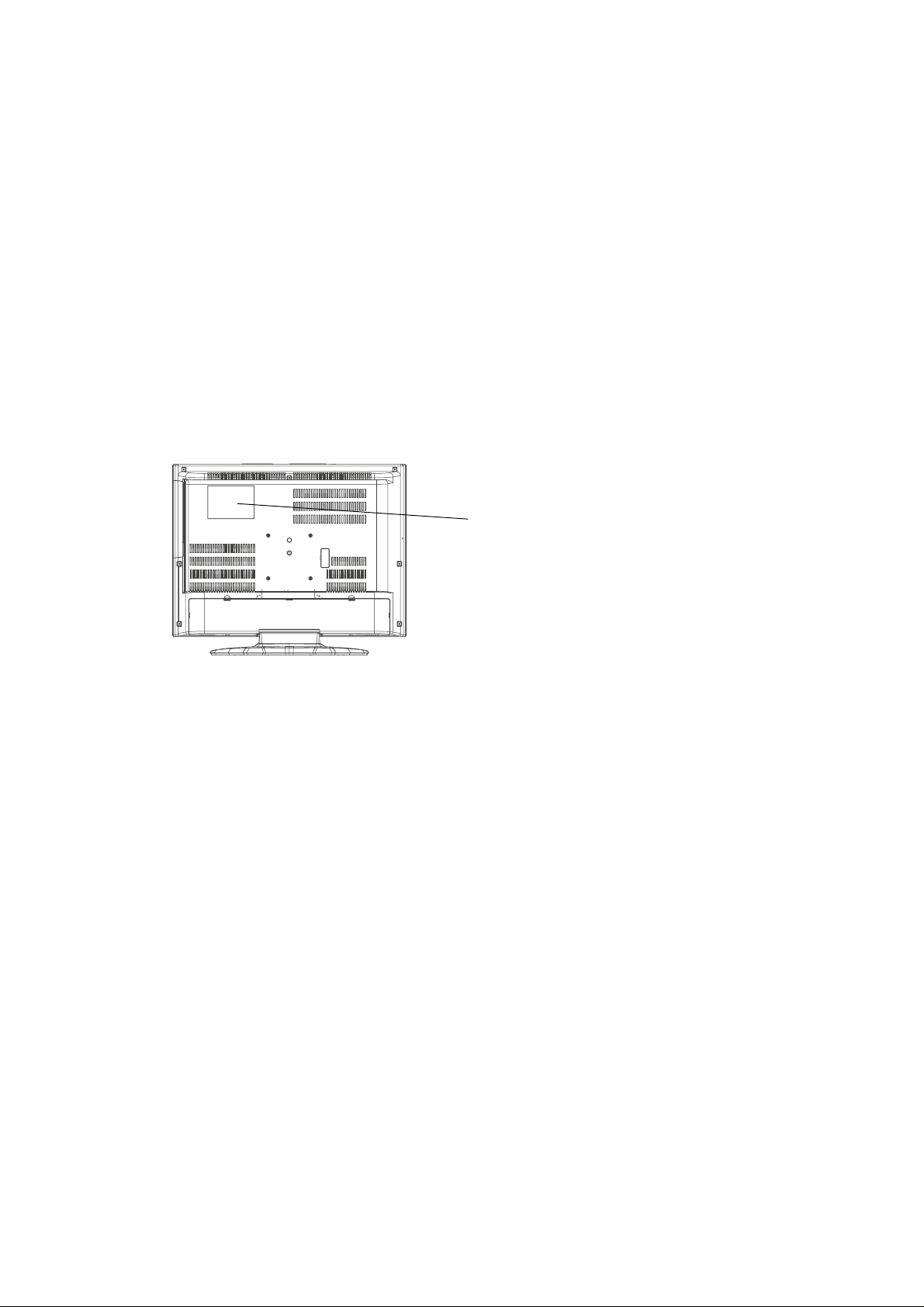
Location of the required Marking
The rating sheet and the safety caution are on the rear of the unit.
EMPLOYS A LASER SYSTEM.
CERTIFICATION: COMPLIES WITH FDA
RADIA TION PERFORMANCE STANDARDS,
21 CFR SUBCHAPTER J.
PREPARATION OF SERVICING
The laser diode used for a pickup head may be destroyed with external static electricity.
Moreover, even if it is operating normally after repair, when static electricity discharge is received at the
time of repair, the life of the product may be shortened.
Please perform the following measure against static electricity, be careful of destruction of a laser diode
at the time of repair.
• Place the unit on a workstation equipped to protect against static electricity, such as conductive mat.
• Soldering iron with ground wire or ceramic type is used.
• A worker needs to use a ground conductive wrist strap for body.
A1-1
Page 3
IMPORTANT SERVICE SAFETY INFORMATION
Safety precautions to be followed during servicing:
1.
Parts marked with an are critical parts for safety. Replace only with the one described in the parts
list.
2.
Before returning the DVD product to the customer, make the appropriate leakage current check or
resistance measurements to ensure that exposed parts are properly insulated from the supply circuit.
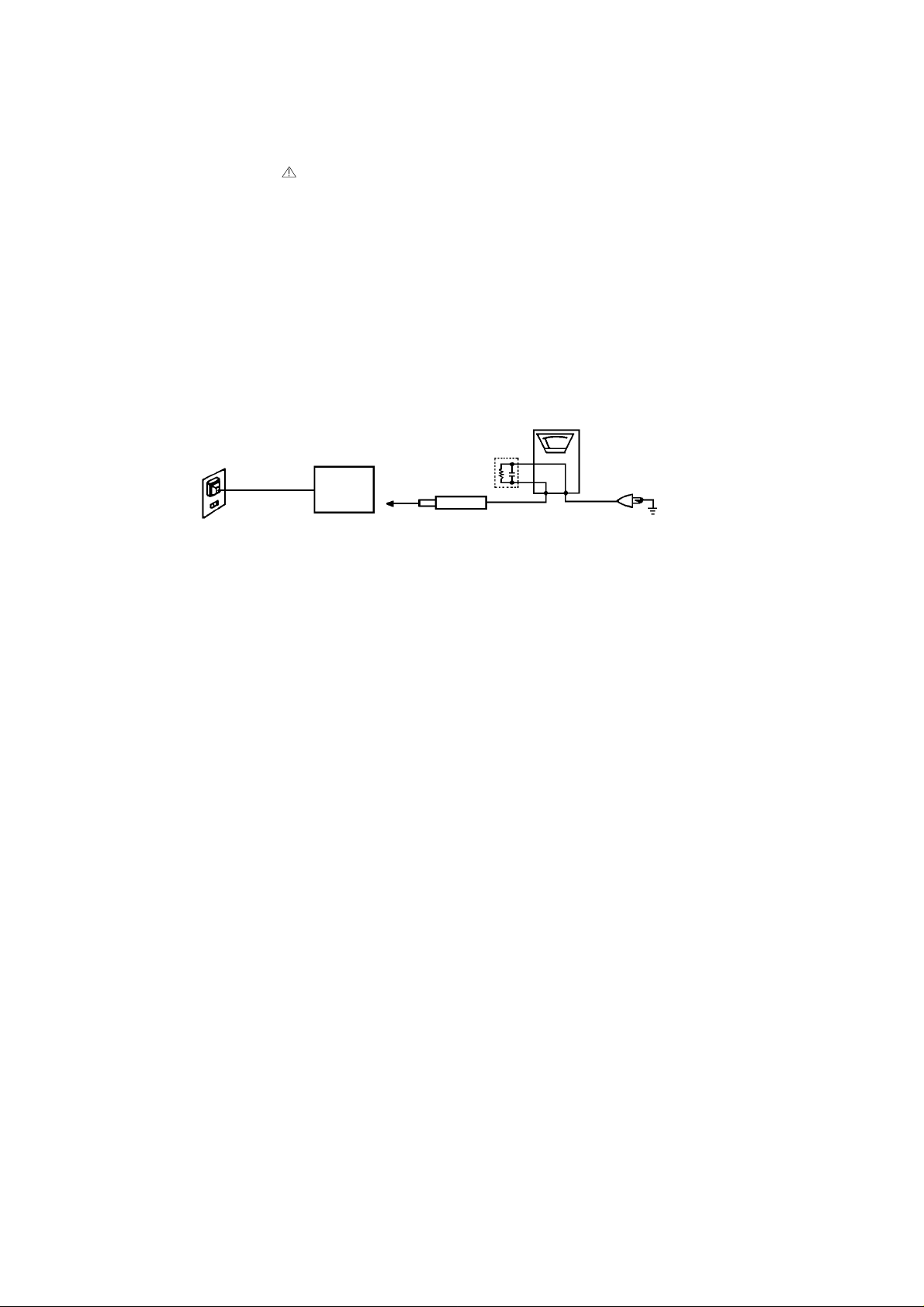
A leakage current check is recommended for this unit. Plug the AC line cord directly into a 120V 60Hz AC
outlet (do not use an isolation transformer for this check). Use a leakage current tester (Fig. 1) or a
metering system which complies with Underwriters Laboratories (UL 1492P). Measure for current from all
exposed metal parts of the cabinet to a known earth ground: particularly, any exposed metal part having a
return path to the chassis. Any current measured must not exceed 0.5mA. Any measurement not within
the limits outlined above are indicative of a potential shock hazard and corrective action must be taken
before returning the unit to the customer.
(Reading should not be above 0.5mA)
Leakage Current Tester
PRODUCT UNDER TEST
1.5K ohm
0.15 µF
2-Blade polarized
type cord set
Test all exposed
metal surfaces
TEST PROBE
Fig. 1 AC Leakage Test
KNOWN EARTH
GROUND
A1-2
Page 4

IMPORTANT SAFEGUARDS
1) Read these instructions.
2) Keep these instructions.
3) Heed all warnings.
4) Follow all instructions.
5) Do not use this apparatus near water.
6) Clean only with dry cloth.
7) Do not block any ventilation openings. Install in accordance with the manufacturer's instructions.
8) Do not install near any heat sources such as radiators, heat registers, stoves, or other apparatus (including
amplifiers) that produce heat.
9) Do not defeat the safety purpose of the polarized or grounding-type plug. A polarized plug has two blades
with one wider than the other. A grounding type plug has two blades and a third grounding prong. The wide
blade or the third prong are provided for your safety. If the provided plug does not fit into your outlet,
consult an electrician for replacement of the obsolete outlet.
10) Protect the power cord from being walked on or pinched particularly at plugs, convenience receptacles, and
the point where they exit from the apparatus.
11) Only use attachments/accessories specified by the manufacturer.
12) Use only with the cart, stand, tripod, bracket, or table specified by the manufacturer, or sold with the apparatus. When a cart is used, use caution when
moving the cart/apparatus combination to avoid injury from tip-over.
13) Unplug this apparatus during lightning storms or when unused for long
periods of time.
14) Refer all servicing to qualified service personnel. Servicing is required when
the apparatus has been damaged in any way, such as power-supply cord or
plug is damaged, liquid has been spilled or objects have fallen into the
apparatus, the apparatus has been exposed to rain or moisture, does not operate normally, or has been
dropped.
15) Apparatus shall not be exposed to dripping or splashing and that no objects filled with liquids, such a vases,
shall be placed on the apparatus.
16) An outside antenna system should not be located in the vicinity of overhead power lines or other electric
light or power circuits, or where it can fall into such power lines or circuits. When installing an outside
antenna system, extreme care should be taken to keep from touching such power lines or circuits, as
contact with them might be fatal.
17) Do not overload wall outlets and extension cords, as this can result in a risk of fire or electric shock.
18) Do not push objects through any openings in this unit, as they may touch dangerous voltage points or short
out parts that could result in fire or electric shock. Never spill or spray any type of liquid into the unit.
PORTABLE CART WARNING
(symbol provided by RETAC)
S3126A
A1-3
Page 5
IMPORTANT SAFEGUARDS (CONTINUED)
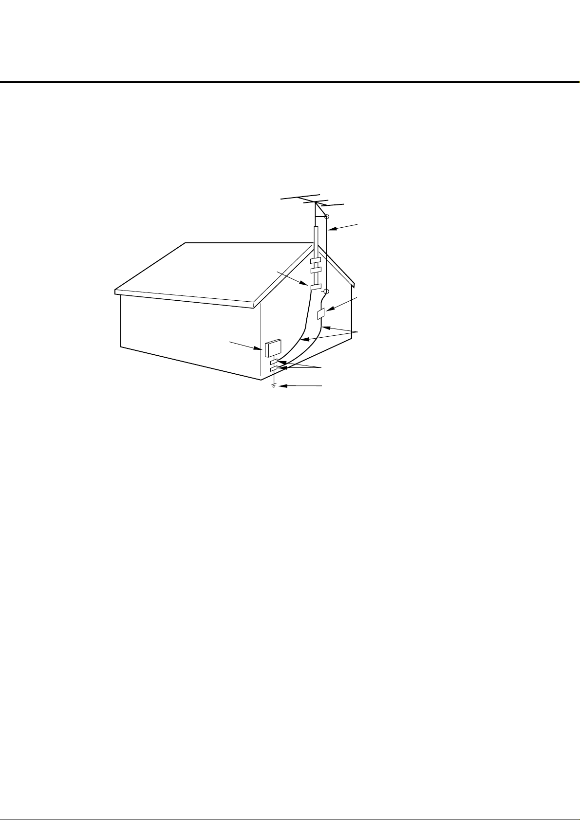
19) If an outside antenna or cable system is connected to the unit, be sure the antenna or cable system is
grounded to provide some protection against voltage surges and built-up static charges, Section 810 of the
National Electrical Code, ANSI/NFPA 70, provides information with respect to proper grounding of the mast
and supporting structure, grounding of the lead-in wire to an antenna discharge unit, size of grounding
conductors, location of antenna discharge unit, connection to grounding electrodes, and requirements for
the grounding electrode.
EXAMPLE OF ANTENNA GROUNDING AS PER THE
NATIONAL ELECTRICAL CODE
ANTENNA LEAD
IN WIRE
GROUND
CLAMP
ANTENNA
DISCHARGE UNIT
(NEC SECTION 810-20)
ELECTRIC SERVICE
EQUIPMENT
GROUND CLAMPS
NEC-NATIONAL ELECTRICAL CODE
S2898A
20) When replacement parts are required, be sure the service technician uses replacement parts specified by
the manufacturer or those that have the same characteristics as the original part.
Unauthorized substitutions may result in fire, electric shock or other hazards.
21) Upon completion of any service or repairs to this unit, ask the service technician to perform safety checks to
determine that the unit is in proper operating condition.
22) Keep your fingers clear of the disc slot as it is closing. It may cause injury.
23) When you connect the product to other equipment, turn off the power and unplug all of the equipment from
the wall outlet. Failure to do so may cause an electric shock and serious personal injury. Read the owner's
manual of the other equipment carefully and follow the instructions when making any connections.
24) Reduce the volume to the minimum level before you turn on the product. Otherwise, sudden high volume
sound may cause hearing or speaker damage.
POWER SERVICE GROUNDING
ELECTRODE SYSTEM
(NEC ART 250, PART H)
GROUNDING CONDUCTORS
(NEC SECTION 810-21)
A1-4
Page 6

IMPORTANT SAFEGUARDS (CONTINUED)
25) Do not allow the product to output distorted sound for an extended period of time. It may cause speaker
overheating and fire.
26) When you use the headphones, keep the volume at a moderate level. If you use the headphones continuously with high volume sound, it may cause hearing damage.
27) Do not look into the opening of the disc slot or ventilation opening of the product to see the source of the
laser beam. It may cause eye damage.
28) Do not use a cracked, deformed, or repaired disc. These discs are easily broken and may cause serious
personal injury and product malfunction.
29) This reminder is provided to call the cable TV system installer’s attention to Article 820-40 of the NEC that
provides guidelines for proper grounding and, in particular, specifies that the cable ground shall be connected to the grounding system of the building, as close to the point of cable entry as practical.
CONDENSATION
Moisture will form in the operating section of the player if the player is brought from cool surroundings into a
warm room or if the temperature of the room rises suddenly. When this happens, player's performance will
be impaired.
To prevent this, let the player stand in its new surroundings for about an hour before switching it on, or
make sure that the room temperature rises gradually.
Condensation may also form during the summer if the player is exposed to the breeze from an air conditioner. In such cases, change the location of the player.
HOW TO HANDLE THE LCD PANEL
• Do not press hard or jolt the LCD panel. It may cause the LCD panel glass to break and injury may occur.
• If the LCD panel is broken, make absolutely sure that you do not touch the liquid in the panel. This may cause
skin inflammation.
If the liquid gets in your mouth, immediately gargle and consult with your doctor. Also, if the liquid gets in
your eyes or touches your skin, consult with your doctor after rinsing for at least 15 minutes or longer in clean
water.
A1-5
Page 7
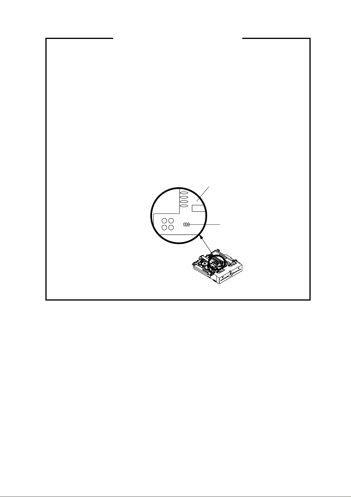
WHEN REPLACING DVD DECK
[ When removing the DVD Deck ]
Before removing Pick Up PCB and DVD PCB connector, the short circuit the position shown in Fig. 1
using a soldering iron. If you remove the DVD Deck with no soldering, the Laser may be damaged.
[ When installing the DVD Deck ]
Remove all the soldering on the short circuit position after the connection of Pick Up PCB and DVD
PCB connector.
NOTE
Before your operation, please read “PREPARATION OF SERVICING”.
•
Use the Lead Free solder.
•
Manual soldering conditions
•
• Soldering temperature: 350 ± 5˚C
• Soldering time: Within 2 seconds
• Soldering combination: Sn-3.0Ag-0.5Cu
When Soldering/Removing of solder, use the draw in equipment over the Pick Up Unit to keep the
•
Flux smoke away from it.
Pick Up PCB
Fig. 1
Short circuit using a
soldering iron.
A1-6
Page 8
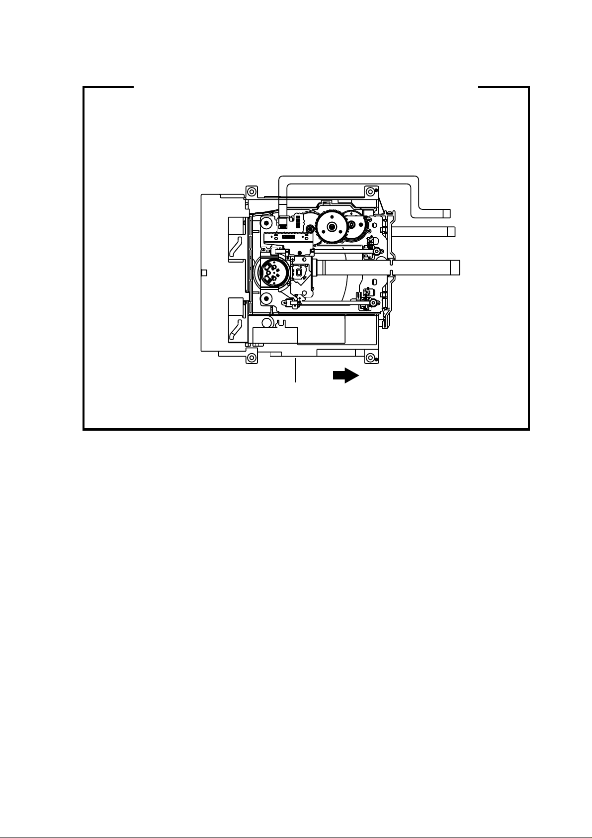
DISC REMOVAL METHOD AT NO POWER SUPPLY
1.
Remove the Back Cabinet and Angle Deck. (Refer to item 1 of the DISASSEMBLY INSTRUCTIONS.)
2.
Slide the Belt Loading toward the arrow direction by hand to release the lock. (Refer to Fig. 1)
3.
Take out the Disc from the DVD Deck. Be careful not to scratch on the Disc.
DVD Deck
Belt Loading
Fig. 1
PARENTAL CONTROL - RATING LEVEL
4 DIGIT PASSWORD CANCELLATION
If the stored 4 digit password in the Rating Level menu needs to be cancelled, please follow the steps below.
Turn Unit ON.
1.
Set the DVD to the Stop Mode.
2.
Check that ‘No disc’ is displayed on the screen.
3.
Press and hold the ‘STOP’ button on the front panel.
4.
Simultaneously press and hold the ‘7’ key on the remote control unit.
5.
Hold both keys for more than 2 seconds.
6.
The On Screen Display message ‘PASSWORD CLEAR’ will appear.
7.
The 4 digit password has now been cleared.
8.
A1-7
Page 9
GENERAL SPECIFICATIONS
G-1 TV LCD LCD Size / Visual Size 20.04 inch / 508.9mmV
G-2 DVD System Color System NTSC
G-3 Tuning Broadcasting System US System M
G-4 Signal Video Signal Input Level 1 V p-p/75 ohm
G-5 Power Power Source AC 120V, 60Hz
G-6 Regulation Safety UL/CSA/NOM
G-7 Temperature Operation +5oC ~ +40oC
G-8 Operating Humidity Less than 80% RH
G-9 Clock and Clock Yes
System LCD Type Color TFT LCD
Number of Pixels 1366(H) x 768(V)
View Range Left/Right 88/88 degree
Up/Down 88/88 degree
Color System NTSC
Speaker 2 Speaker
Position Front
Size 1.8 x 3.9 inch
Impedance 8 ohm
Sound Output Max 2.5W + 2.5W
10%(Typical) ---
Disc DVD, CD-DA, CD-R/RW
DVD-R/RW (Video Format Only)
Disc Diameter 120 mm , 80 mm
Drive DSM-2
Search speed Fwd 4 step
Actual 2-45 times (DVD)
4-40 times (CD)
Rev 4 step
Actual 2-45 times (DVD)
4-40 times (CD)
Slow speed Fwd 1/7 -1/2 times
Actual --
Rev 1/7 -1/2 times
Actual --
System Tuner and System 1Tuner
Receive CH Destination US (W/CABLE)
CH Coverage 2~69, 4A, A-5~A-1, A~I, J~W, W+1~W+84
Intermediate Picture(FP) 45.75MHz
Frequency Sound(FS) 41.25MHz
FP-FS 4.50MHz
Preset CH No
Stereo/Dual TV Sound US-Stereo
Tuner Sound Muting Yes
Output Level --
S/N Ratio (Weighted) --
Horizontal Resolution at DVD Mode --
-RGB Signal Output Level -Audio Signal Input Level 0.85 V p-p/50k ohm
Output Level at DVD --
at TV -Digital Output Level 0.5 V p-p/75 ohm
S/N Ratio at DVD (Weighted) -Harmonic Distortion -Frequency Response : at DVD --
at Video CD --
at SVCD --
at CD --
DC --
Power Consumption at AC 90W at 120V 60Hz
at DC -Stand by (at AC) 1W at 120V 60Hz
Energy Star Yes
Per Year -- kWh/Year
Protector Power Fuse Yes
Safety Circuit Yes
IC Protector(Micro Fuse) Yes
Radiation FCC/IC
Laser DHHS
Storage -20oC ~ +60oC
Timer Sleep Timer Max Time 120 Min
Step 10 Min
On Timer Program No
Off Timer Program No
Game Timer No
Wake Up Timer No
Timer Back-up (at Power Off Mode) more than -- Min Sec
A2-1
Page 10
GENERAL SPECIFICATIONS
G-10 Remote Unit RC-MR
Control Glow in Dark Remocon No
Remocon Format SHARP
Format TV:SHARP, DVD:KASEIKYO
Custom Code TV:SHARP 15bit, DVD:KASEIKYO 48bit
Power Source Voltage(D.C) 3V
Total Keys 47 Keys
Keys
UM size x pcs UM-3 x 2 pcs
POWER
DISPLAY
SLEEP
VIEW MODE
INPUT SELECT
1
2
3
4
5
6
7
8
9
0
MUTE
AUDIO
VOL+
VOLCH+
CHLEFT/SLOWENTER
RIGHT/SLOW+
UP
DOWN
SETUP/TV MENU
EXIT/CANCEL
RETURN
SUBTITLE
TV/DVD
OPEN/CLOSE(EJECT)
FWD(SEARCH+)
REV(SEARCH-)
SKIP+
SKIPPAUSE/STILL
PLAY
STOP
PLAY MODE
ANGLE
ZOOM
DVD MENU
TOP MENU
REPAT A-B
MARKER
DIRECT SKIP(JUMP)
FREEZE
Yes
Yes
Yes
Yes
Yes
Yes
Yes
Yes
Yes
Yes
Yes
Yes
Yes
Yes
Yes
Yes
Yes
Yes
Yes
Yes
Yes
Yes
Yes
Yes
Yes
Yes
Yes
Yes
Yes
Yes
Yes
Yes
Yes
Yes
Yes
Yes
Yes
Yes
Yes
Yes
Yes
Yes
Yes
Yes
Yes
Yes
Yes
No
A2-2
Page 11
GENERAL SPECIFICATIONS
G-11 Features Auto Shut Off Yes
(TV) Auto Search No
Power On Memory Yes
Comb Filter Yes
Game Position No
Auto Setup(Language/CH Program) No
Picture Setting(TV) Yes
AV Mode(Picture Preference) Yes
Brightness , Contrast , Color Yes
Tint Yes
Sharpness Yes
Color Temperature Yes
Cable Clear No
Picture Setting(PC) Yes
BRIGHTNESS , CONTRAST Yes
HOR POSITION , VER POSITION Yes
PHASE , CLOCK Yes
AUTO ADJUST No
RED , GREEN , BLUE Yes
Audio MTS Yes
Tone Control (Bass/Treble/Balance) Yes
Stable Sound No
Surround Yes
BBE No
SRS WOW (SRS 3D/Focus/Tru Bass) No
Variable Audio Out No
Tuning CH Program Yes
Air/Cable Yes
ADD/DELETE Yes
Label CH Label Yes
Video Label Yes
Favorite CH No
V-Chip Yes
Type USA Type
RRT Setup
Lock Hotel Lock No
Channel Lock No
Video Lock No
Panel Lock No
OSD Language
Closed Caption
CC Advanced
View Mode (Picture Size) Yes(SIDE BAR/S.STRETCH/ZOOM/STRETCH)
Picture Scroll Yes
Cinema Mode Yes
Aspect Yes
Backlight Yes
PFC(Power Factor circuit)
Freeze frame No
PIP/POP No
Direct Input Selection Yes
PC Monitor Input Yes
VGA (640x480) Yes (60Hz)
VGA (720x400) Yes (70Hz)
WVGA (848x480) Yes (60Hz)
SVGA (800x600) Yes (60Hz)
XGA (1024x768) Yes (60Hz)
WXGA (1280x768) Yes (60Hz)
WXGA (1280x720) Yes (60Hz)
WXGA (1360x768) Yes (60Hz)
SXGA (1280x1024) No
HDMI Input Yes
VGA (640x480) Yes (60Hz)
720x480i (4:3) Yes (60Hz)
720x480i (16:9) Yes (60Hz)
720x480p (4:3) Yes (60Hz)
720x480p (16:9) Yes (60Hz)
720x576i (4:3) No
720x576i (16:9) No
720x576p (4:3) No
720x576p (16:9) No
1280x720p Yes (60Hz)
1920x1080i Yes (60Hz)
3 -D
English French Spanish
Yes
No
No
No
A2-3
Page 12
GENERAL SPECIFICATIONS
Component Input Yes
Features Tray Lock No
(DVD) Video CD Playback No
SVCD Playback
MP3 Playback Yes
Divx Playback No
JPEG Yes
WMA Yes
Digital Out (Dolby Digital) Yes
Down Mix Out (Dolby Digital) Yes
Closed Caption Yes
Screen Saver No
Audio DAC 192kHz / 24bit
G-12 Accessories Owner's Manual Language English/French/Spanish
Remote Control Unit Yes
Rod Antenna
Loop Antenna
U/V Mixer
DC Car Cord (Center+)
Guarantee Card
Warning Sheet
Circuit Diagram
Antenna Change Plug
Service Facility List
Important Safeguard
Dew/AHC Caution Sheet
Quick Set-up Sheet
Battery Yes
AC Adapter
AC Cord (for AC Adapter)
AV Cord (2Pin-1Pin)
Registration Card (NDL Card) Yes
300ohm to 75ohm Antenna Adapter
Sheet Information (Return)
Sheet Information (HDMI) No
Screw for wall hanging No
720x480i (4:3) Yes (60Hz)
720x480i (16:9) Yes (60Hz)
720x480p (4:3) Yes (60Hz)
720x480p (16:9) Yes (60Hz)
720x576i (4:3) No
720x576i (16:9) No
720x576p (4:3) No
720x576p (16:9) No
1280x720p Yes (60Hz)
1920x1080i Yes (60Hz)
No
Overlay Graphics And Text No
Command List No
Entry Point Jump No
DMF Support No
(MPEG) Yes
(PCM) Yes
(DTS) Yes
(DTS) No
w/Guarantee Card Yes
No
Poles -Terminal --
No
Terminal --
No
No
No
No
No
No
No
No
No
No
UM size x pcs UM-3 x 2 pcs
OEM Brand No
No
No
No
No
No
A2-4
Page 13
GENERAL SPECIFICATIONS
G-13 Interface Switch Top Power (Tact) Yes
Indicator Power / Stand-by Yes(GREEN / RED)
Terminals Rear Video Input 1 RCA x 1
Side Video Input 2 No
G-14 Set Size Approx. W x D x H (mm) 553 x 228 x 448
G-15 Weight Net (Approx.) 9.2kg (20.3 lbs)
G-16 Carton Master Carton No
Gift Box Material Double/White
Drop Test 1 Corner / 3 Edges / 6 Surfaces
Container Stuffing (40' container) 492
G-17 Material Cabinet Front PS 94V0 NON-DECABROM
PCB Non-Halogen Demand No
G-18 Environment Environmental standard requirement (by buyer) Green PROCUREMENT of SHARP
Pb-Free Phase 3 (Phase 3A)
Channel Up/Menu Up Yes
Channel Down/Menu Down Yes
Volume Up/Menu > Yes
Volume Down/Menu < Yes
Menu Yes
Play Yes
Eject Yes
Skip+, Search+ Yes
Skip-, Search- Yes
Still/Pause No
Stop Yes
Main Power SW No
Input Select Yes
Power No
Stand-by No
On Timer No
Audio Input 1
S - Input 1
Video Input 2 RCA x 1
Audio Input 2
S- Input 2 No
Video Output No
Audio Output No
Component Input
Analog Audio RCA x 2(L/MONO, R)
HDMI Input
Analog Audio PC Monitor Audio Input Alternative
PC Monitor Input
Analog Audio RCA x 2(L/MONO, R)
Digital Audio Output Coaxial (DVD Only)
DC Jack No
VHF/UHF Antenna Input
Other Terminal
AC Outlet No
Audio Input 2 No
PC Monitor Input(w/ Analog Audio L/R) No
Other Terminal No
w/o Handle, Stand Approx. W x D x H (mm)
Net w/o Handle, Stand (Approx.) 7.9kg (17.5 lbs)
Gross (Approx.) 11.5kg (25.4 lbs)
Content --- Sets
Material --- / --Dimensions W x D x H(mm) --Description of Origin ---
W/Color Photo Label No
W/Handle No
Dimensions W x D x H(mm) 654 x 338 x 565
Description of Origin Yes
Height (cm) 62
Rear PS 94V0 NON-DECABROM
Eyelet Demand Yes
Measures for Whisker Yes
RCA x 2(L/MONO, R)
Yes
RCA x 2(L/MONO, R)
RCA x 3
HDMI x 1
Dsub15pin x 1
F Type
Headphone
553 x 110 x 403
Sets
A2-5
Page 14
DISASSEMBLY INSTRUCTIONS
1. REMOVAL OF MECHANICAL PARTS
AND P.C. BOARDS
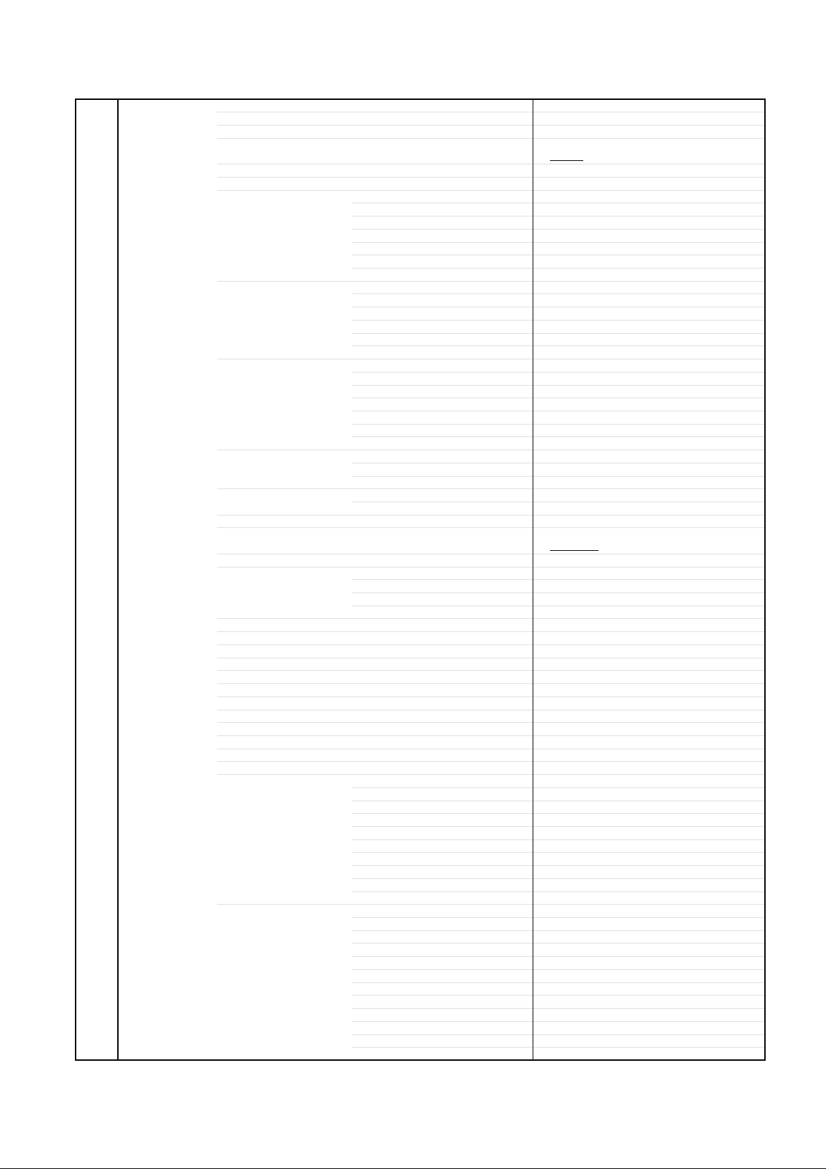
1-1: BACK CABINET (Refer to Fig. 1-1)
1.2.Remove the 19 screws 1.
Remove the Back Cabinet in the direction of arrow.
1
1
1
1
1
1
1
1
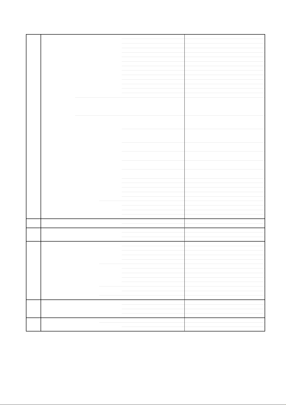
1-2:
STAND ASS'Y/ANGLE BACK 1/2/PLATE JACK 1/2
(Refer to Fig. 1-2)
1.
Remove the 4 screws 1.
2.
Remove the Stand Ass'y in the direction of arrow (A).
3.
Remove the 4 screws 2.
4.
Remove the 6 screws 3.
5.
Remove the Angle Back 1/2 in the direction of arrow (B).
6.
Remove the 4 screws 4.
7.
Remove the Plate Jack 2 in the direction of arrow (C).
8.
Remove the 11 screws 5.
9.
Remove the Plate Jack 1 and Shield Jack in the direction
of arrow (D).
2
2
3
3
Angle Back 1
(B)
1
1
2
2
3
3
3
Plate Jack 2
(C)
1
1
1
Back Cabinet
3
4
(A)
1
1
Angle Back 2
1
4
1
1
1
1
Fig. 1-1
1
1
1
Stand Ass'y
5
5
5
5
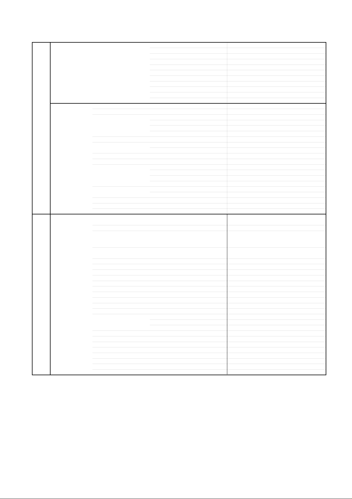
1-3: PCB ASS'Y (Refer to Fig. 1-3)
1.
Disconnect the following connectors:
(CP506, CP507, CP508, CP510, CP511, CP512).
2.
Remove the 9 screws 1.
3.
Remove the Holder AC-Inlet and Power PCB in the
direction of arrow (A).
4.
Disconnect the following connectors:
(CP802, CP803, CP2200, CP3201, CP3602, CP7203).
5.
Remove the 10 screws 2.
6.
Remove the Shield Scaler and Scaler PCB in the
direction of arrow (B).
7.
Disconnect the following connectors:
(CP301, CP303, CP2403, CP2404, CP4202).
8.
Remove the 6 screws 3.
9.
Remove the DigitalPCB and AV PCB in the direction of
arrow (C).
10.
Remove the 2 screws 4.
11.
Remove the Remocon PCB in the direction of arrow (D).
12.
Remove the 8 screws 5.
13.
Remove the Plate Button, Operation PCB and Operation
2 PCB in the direction of arrow (E).
2
2
Holder AC-Inlet
1
1
1
1
Power PCB
Operation 2 PCB
5
Plate Button
(E)
(A)
1
1
1
5
5
2
2
2
2
1
1
5
5
5
Operation PCB
2
Shield Scaler
2
2
Scaler PCB
2
3
(B)
5
5
(C)
Digital PCB
3
3
3
3
AV PCB
3
4
4
Remocon PCB
(D)
Fig. 1-3
(D)
Plate Jack 1
Shield Jack
Fig. 1-2
B1-1
Page 15
DISASSEMBLY INSTRUCTIONS
1-4: DVD MT PCB/DVD DECK (Refer to Fig. 1-4)
1.
Short circuit the position shown in Fig. 1-4 using a
soldering iron. If you remove the DVD Deck with no
soldering, the Laser may be damaged.
2.
Disconnect the following connectors:
(CP2301, CP2302 and CP2303).
3.
Remove the 4 screws 1.
4.
Remove the Shield MPEG, Shield FCC and DVD MT
PCB in the direction of arrow (A).
5.
Remove the 4 screws 2.
6.
Remove the DVD Deck in the direction of arrow (A).
7.
Remove the 2 screws 3.
8.
Remove the Angle Deck-R in the direction of arrow (B).
9.
Remove the 2 screws 4.
10.
Remove the Angle Deck-L in the direction of arrow (C).
Short circuit using a
soldering iron.
2
Pick Up PCB
Angle Deck-R
SHIELD MPEG
4
3
2
2
(B)
DVD Deck
1
1
1
2
(C)
4
Angle Deck-L
3
1
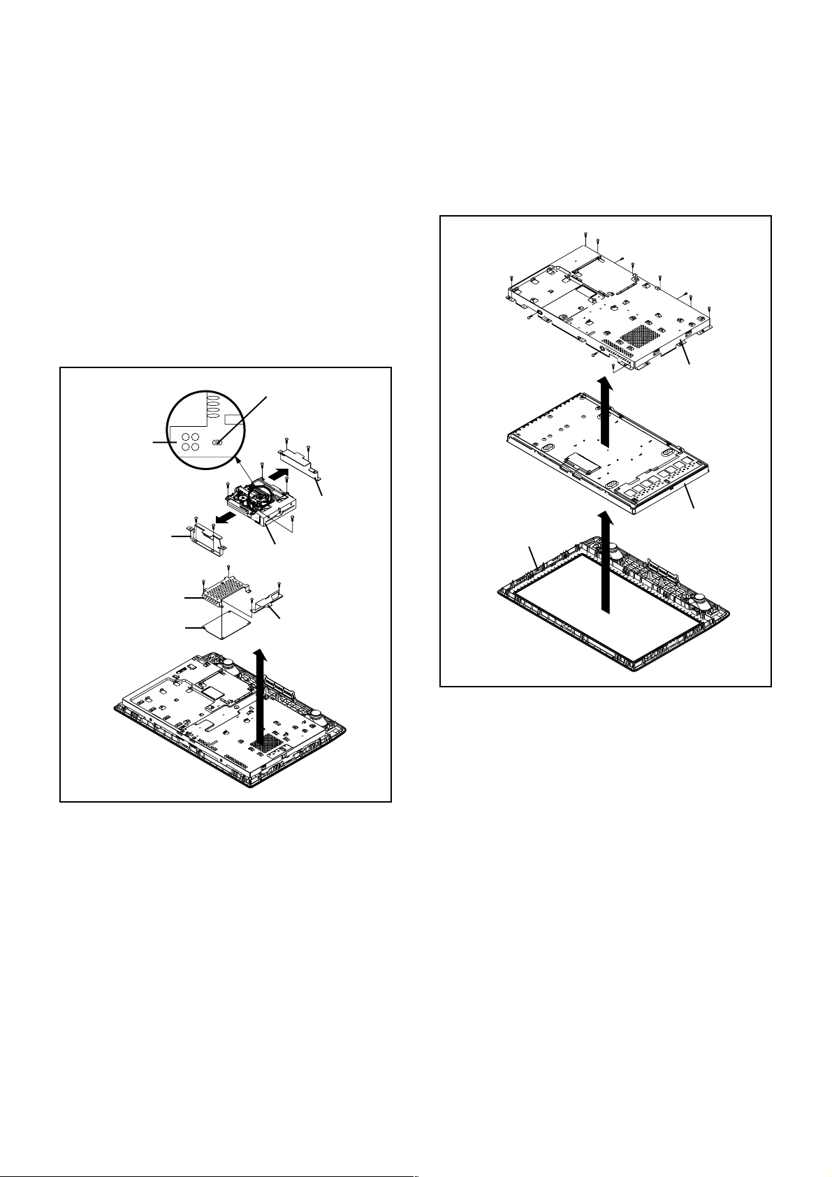
1-5: LCD COVER/LCD PANEL (Refer to Fig. 1-5)
1.
Remove the 8 screws 1.
2.
Remove the LCD Cover in the direction of arrow (A).
3.
Remove the 4 screws 2.
4.
Remove the LCD Panel in the direction of arrow (B).
1
1
2
1
(B)
1
2
1
1
LCD Cover
LCD Panel
1
2
Front Cabinet
2
1
(A)
DVD MT PCB
SHIELD FCC
(A)
Fig. 1-4
NOTE
Before your operation, please read “PREPARATION OF
1.
SERVICING”.
Use the Lead Free solder.
2.
Manual soldering conditions
3.
• Soldering temperature: 350 ± 5˚C
• Soldering time: Within 2 seconds
• Soldering combination: Sn-3.0Ag-0.5Cu
When Soldering/Removing of solder, use the drawing
4.
equipment over the Pick Up Unit to keep the Flux smoke
away from it.
When installing the DVD Deck, remove all the soldering on
5.
the short circuit position after the connection of Pick Up
PCB and DVD PCB connector.
Fig. 1-4
B1-2
Page 16
DISASSEMBLY INSTRUCTIONS
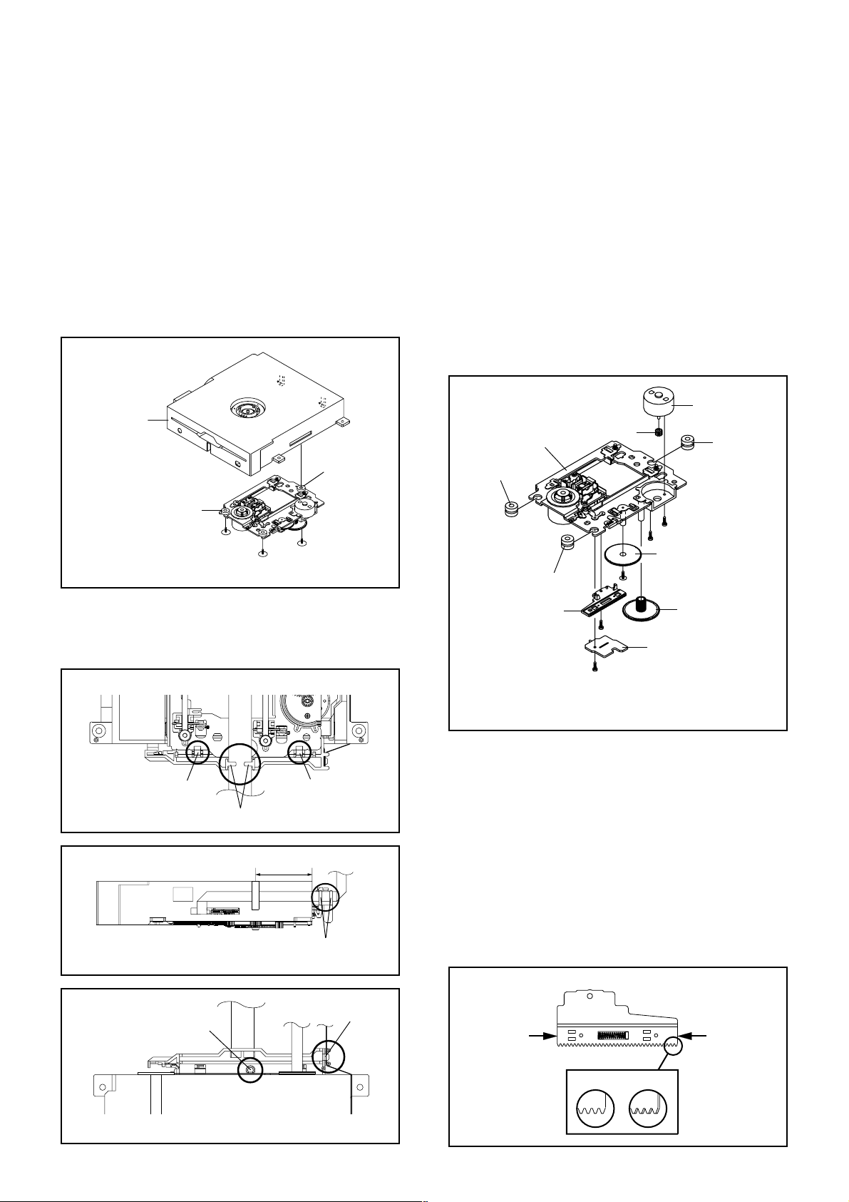
2. REMOVAL OF DVD DECK PARTS
NOTE
1. Disassemble only the DVD DECK PARTS parts listed
here. Minute adjustments are needed if the
disassembly is done. If the repair is needed except
listed parts, replace the DVD MECHA ASS'Y.
2-1: TRAVERSE ASS'Y (Refer to Fig. 2-1-A)
Remove the 3 screws 1.
1.
Unlock the 2 supports 2.
2.
Remove the Insulator (R) from the Loader Sub Ass'y.
3.
Remove the Traverse Ass'y.
4.
2
Loader Sub Ass'y
2
2-2:
SWITCH PCB ASS'Y/GEAR MIDDLE/GEAR FEED/RACK
FEED ASS'Y/FEED MOTOR (Refer to Fig. 2-2-A)
Remove the Insulator (F).
1.
Remove the Insulator (R).
2.
Unlock the support 1.
3.
Remove the Gear Middle.
4.
Remove the screw 2.
5.
Remove the Rack Feed Ass'y.
6.
Remove the screw 3.
7.
Remove the Switch PCB Ass'y.
8.
Remove the screw 4.
9.
Remove the Gear Feed.
10.
Remove the 2 screws 5.
11.
Remove the Feed Motor.
12.
Remove the Gear Motor.
13.
Feed Motor
Traverse Ass'y
Gear Motor
Insulator (R)
Insulator (R)
Traverse Ass'y
1
• Screw Torque: 2.0 ± 0.3kgf•cm
1
1
Fig. 2-1-A
NOTE
1. In case of the Traverse Ass'y installation, hook the wire
on the Loader Ass'y as shown Fig. 2-2-B to Fig. 2-2-D.
Loader Ass'y (Bottom Side)
Check Lock Check Lock
Check Hook
40 ± 5mm
Loader Ass'y
Fig. 2-1-B
Check Hook
Fig. 2-1-C
Insulator (F)
5
1
5
Gear Feed
Insulator (F)
Rack Feed Ass'y
• Screw Torque: 1.3 ± 0.3kgf•cm (Screw 2)
• Screw Torque: 3.0 ± 0.3kgf•cm (Screw 3)
• Screw Torque: 1.0 ± 0.3kgf•cm (Screw 4, 5)
4
Gear Middle
2
Switch PCB Ass'y
3
Fig. 2-2-A
NOTE
1.
When installing the Rack Feed Ass'y, push both ends to
align the teeth as shown Fig. 2-2-B. Then install it.
2.
In case of the Gear Motor installation, check if the value
of the Fig. 2-2-C is correct.
3.
When installing the wire of the Switch PCB Ass'y, install
it correctly as Fig. 2-2-D.
Manual soldering conditions
• Soldering temperature: 350 ± 5˚C
• Soldering time: Within 4 seconds
• Soldering combination: Sn-3.0Ag-0.5Cu
4.
After the assembly of the Traverse Ass'y, hook the wire
on the Traverse Ass'y as shown Fig. 2-2-E.
Rack Feed Ass'y
Check Hook
Loader Ass'y (Top Side)
Check Hook
Fig. 2-1-D
B2-1
Push
Push
[OK] [NG]
Fig. 2-2-B
Page 17
DISASSEMBLY INSTRUCTIONS
Feed Motor
Check Hook
Gear Motor
Safety surface for pressing
of the insert.
Switch PCB Ass'y
~ SPINDLE MOTOR ~
YELLOW (2)
GREEN (1)
Traverse Ass'y
8.0 ± 0.2mm
Fig. 2-2-C
~ FEED MOTOR ~
WHITE (4)
BROWN (3)
• Install wire from (1) to (4) in order.
Fig. 2-2-D
[ 6 pin FFC ]
40 ± 1mm
Fold
Fold
60 ± 1mm
Fig. 2-3-B
Check Hook
Check Hook
Check Hook
• Loosen the wire in the direction of the arrow.
Fig. 2-2-E
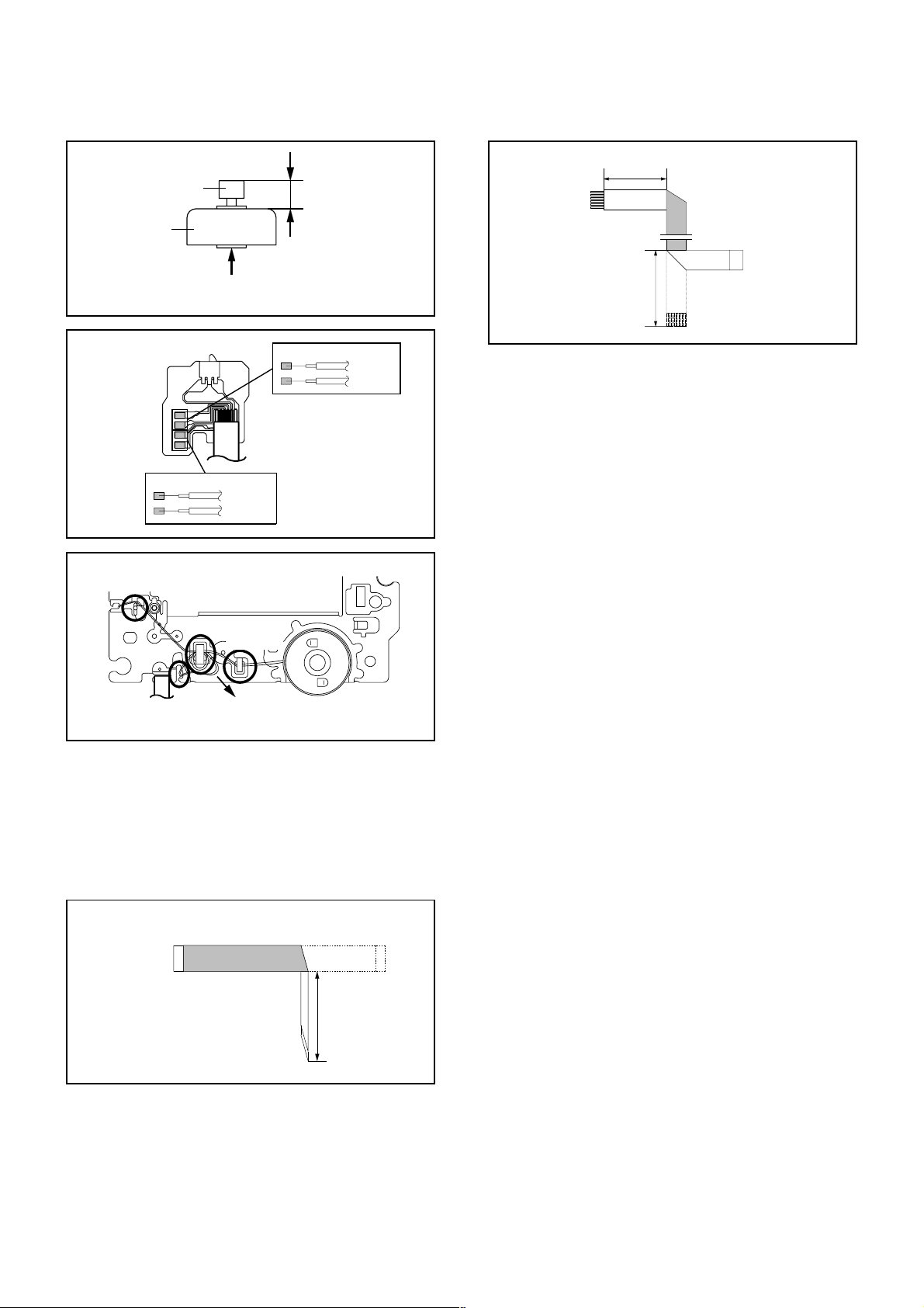
2-3: FFC WIRE HANDLING
1.
When installing the FFC, fold it correctly and install it as
shown from Fig. 2-3-A to Fig. 2-3-B.
NOTE
Do not make the folding lines except the specified
1.
positions for the FFC.
[ 24 pin FFC ]
Fold it by 90˚
To Pick Up PCB
Printing Surface
60 ± 1mm
Fig. 2-3-A
B2-2
Page 18
DISASSEMBLY INSTRUCTIONS
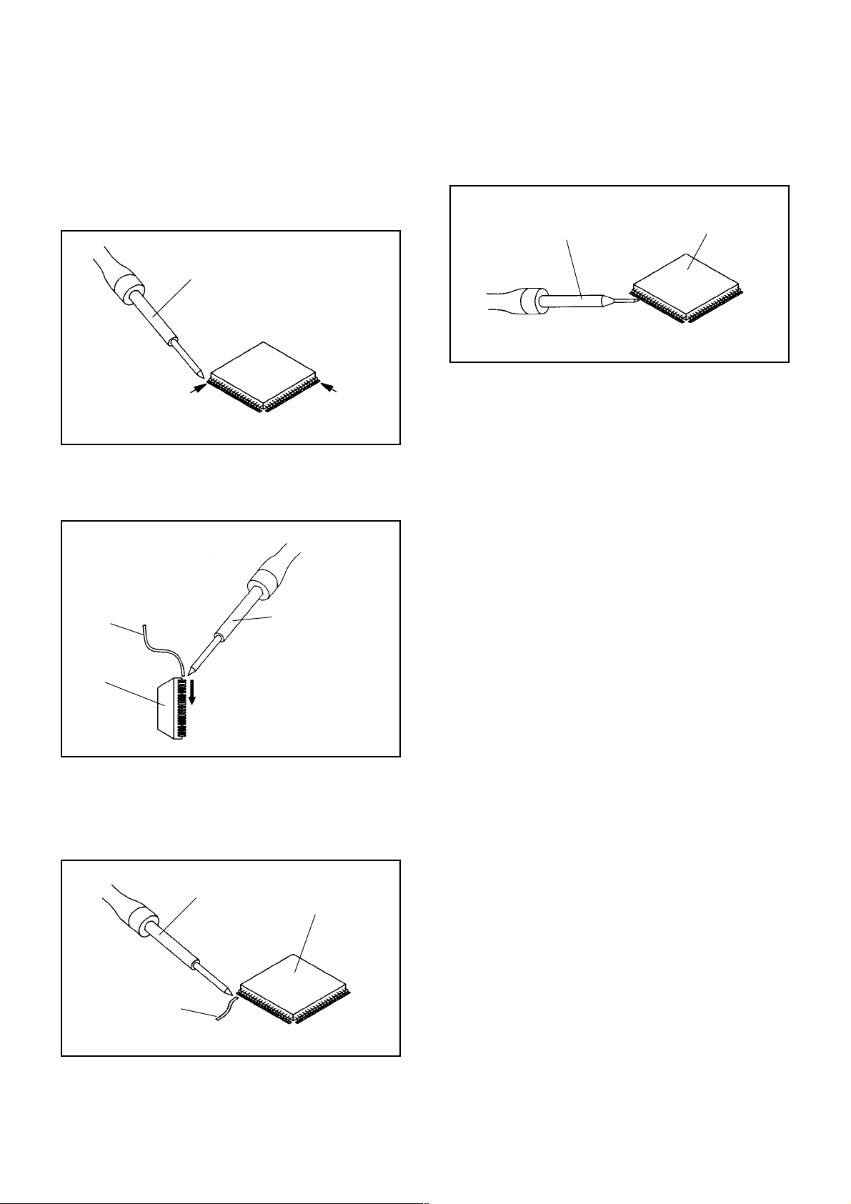
3.
REMOVAL AND INSTALLATION OF
FLAT PACKAGE IC
REMOVAL
Put Masking Tape (cotton tape) around the Flat Package
1.
IC to protect other parts from any damage.
(Refer to Fig. 3-1.)
NOTE
Masking is carried out on all the parts located within
10 mm distance from IC leads.
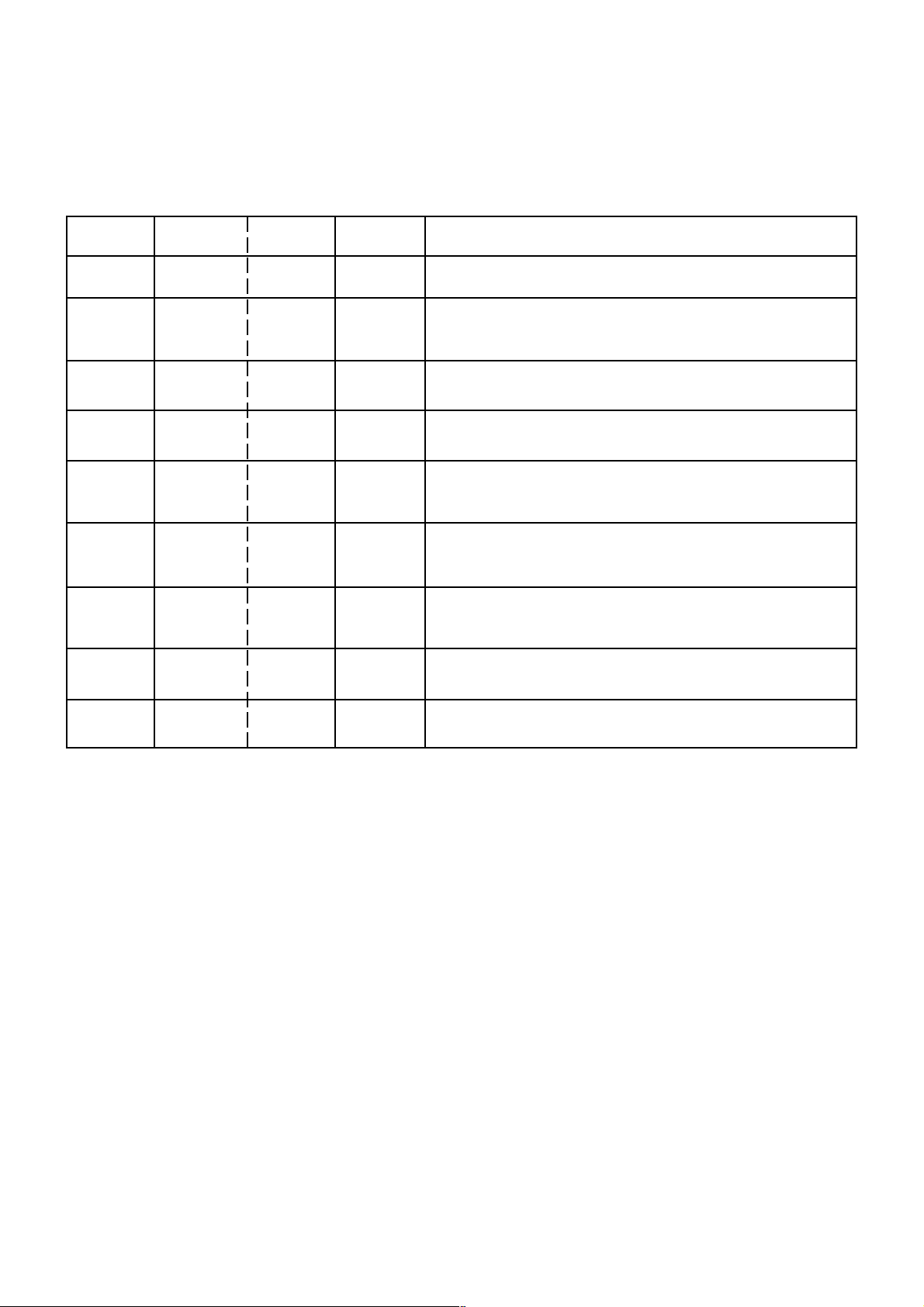
When IC starts moving back and forth easily after
3.
desoldering completely, pickup the corner of the IC using
tweezers and remove the IC by moving with the IC
desoldering machine. (Refer to Fig. 3-3.)
NOTE
Some ICs on the PCB are affixed with glue, so be
careful not to break or damage the foil of each IC
leads or solder lands under the IC when removing it.
Blower type IC
desoldering
machine
Masking Tape
(Cotton Tape)
Heat the IC leads using a blower type IC desoldering
2.
IC
machine. (Refer to Fig. 3-2.)
NOTE
Do not rotate or move the IC back and forth , until IC
can move back and forth easily after desoldering the
leads completely.
Blower type IC
desoldering machine
Fig. 3-1
Tweezers
IC
Peel off the Masking Tape.4.
Absorb the solder left on the pattern using the Braided
5.
Shield Wire. (Refer to Fig. 3-4.)
NOTE
Do not move the Braided Shield Wire in the vertical
direction towards the IC pattern.
Fig. 3-3
Braided Shield Wire
Soldering Iron
IC
Fig. 3-2
IC pattern
Fig. 3-4
B3-1
Page 19
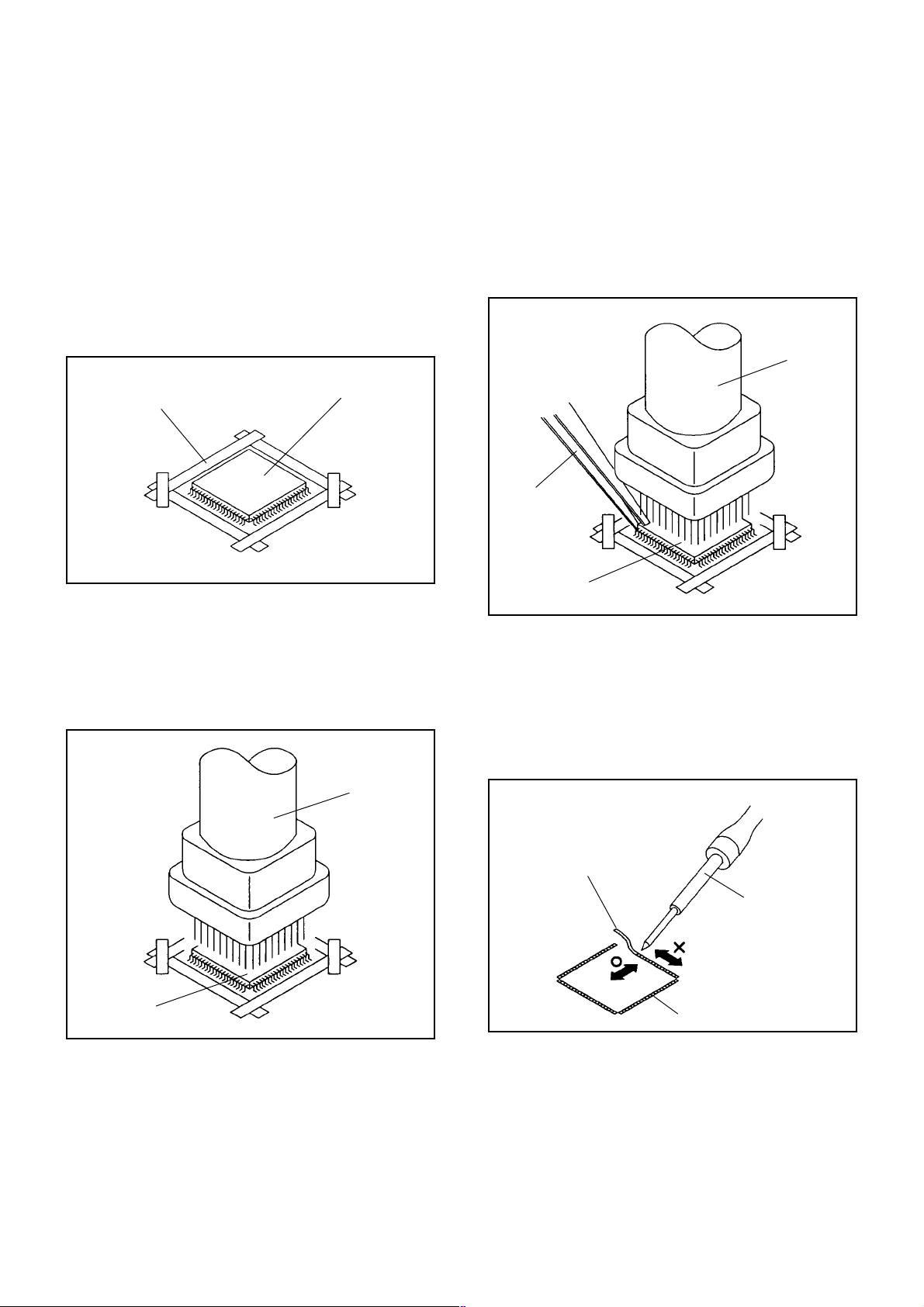
DISASSEMBLY INSTRUCTIONS
INSTALLATION
Take care of the polarity of new IC and then install the
1.
new IC fitting on the printed circuit pattern. Then solder
each lead on the diagonal positions of IC temporarily.
(Refer to Fig. 3-5.)
Soldering Iron
Solder temporarily
Supply the solder from the upper position of IC leads
2.
Solder temporarily
sliding to the lower position of the IC leads.
(Refer to Fig. 3-6.)
Fig. 3-5
When bridge-soldering between terminals and/or the
4.
soldering amount are not enough, resolder using a Thintip Soldering Iron. (Refer to Fig. 3-8.)
Thin-tip Soldering Iron
IC
Fig. 3-8
Finally, confirm the soldering status on four sides of the
5.
IC using a magnifying glass.
Confirm that no abnormality is found on the soldering
position and installation position of the parts around the
IC. If some abnormality is found, correct by resoldering.
NOTE
When the IC leads are bent during soldering and/or
repairing, do not repair the bending of leads. If the
bending of leads are repaired, the pattern may be
damaged. So, always be sure to replace the IC in this
case.
Soldering IronSolder
IC
Absorb the solder left on the lead using the Braided
3.
Supply soldering
from upper position
to lower position
Shield Wire. (Refer to Fig. 3-7.)
NOTE
Do not absorb the solder to excess.
Soldering Iron
IC
Braided Shield Wire
Fig. 3-6
Fig. 3-7
B3-2
Page 20
SERVICE MODE LIST
This unit is provided with the following SERVICE MODES so you can repair, examine and adjust easily.
To enter to the SERVICE MODE function, press and hold both buttons simultaneously on the main unit and on the remote
control for more than the standard time in the appropriate condition. (See below chart.)
Set
Condition
TV mode
TV mode
DVD mode
(No disc)
DVD mode
(No disc)
TV mode
TV mode
ALL mode
DVD mode
(No disc)
Set Key
VOL. DOWN
(Minimum)
VOL. DOWN
(Minimum)
VOL. DOWN
(Minimum)
VOL. DOWN
(Minimum)
VOL. DOWN
(Minimum)
VOL. DOWN
(Minimum)
VOL. DOWN
(Minimum)
Remocon
Key
0 2 sec.
1 2 sec.
4 2 sec.
5 2 sec.
6 2 sec.
8
9 2 sec.
Standard
Time
2 sec.
Operations
Releasing of V-CHIP PASSWORD.
Initialization of factory TV data.
NOTE:
Initialization of factory DVD data.
NOTE: Do not use this for normal servicing.
DVD Write mode.
Refer to the “RE-WRITE FOR DVD FIRMWARE”.
POWER ON total hours are displayed on the screen.
Can be checked of the INITIAL DATA of MEMORY IC.
Refer to the "WHEN REPLACING EEPROM (MEMORY) IC".
Check of the SUM DATA, POWER ON total hours, MICON
VERSION and DIGITAL TV MICON FIRMWARE on the screen.
Refer to the "WHEN REPLACING EEPROM (MEMORY) IC".
Display of the Adjustment MENU on the screen.
Refer to the "ELECTRICAL ADJUSTMENT" (On-Screen Display
Adjustment).
Refer to the “RE-WRITE FOR DVD FIRMWARE”.STOP 1 2 sec.
DVD
If you set factory initialization, the memories are reset such
as the channel setting, and the POWER ON total hours.
DVD mode
(No disc)
STOP 7 2 sec.
Releasing of PARENTAL LOCK.
Refer to the “PARENTAL CONTROL - RATING LEVEL”.
C-1
Page 21
SERVICING FIXTURES AND TOOLS
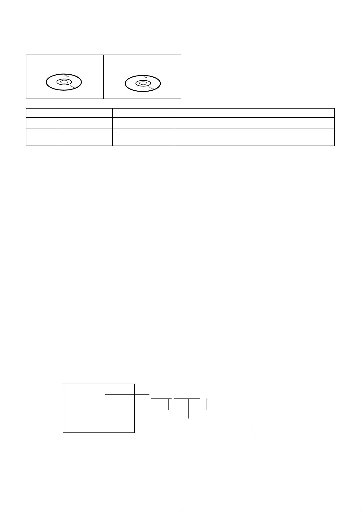
JG176 Up-Date Disc
Ref. No.
JG176
JG176
Part No.
APJG176104
JG176 USA HD DTV ROM
DISC
Parts Name
Up-Date Disc
USA HD DTV ROM
DISC
Remarks
Up-Date of the DVD Firmware
Up-Date of the DIGITAL FirmwareAPJG176096
RE-WRITE FOR DVD FIRMWARE
Turn on the power, and set the DVD mode.
1.
Press both VOL. DOWN button on the set and Channel button (5) on the remote control for more than 2 seconds.
2.
Press VOL. UP/DOWN button on the unit to check if all the keys on the unit do not function.
3.
NOTE: To check if DVD Write mode is set.
When inserting Up-Date Disc at Non DVD Write mode, the read error will happen.
Insert the Up-Date Disc. (Refer to SERVICING FIXTURE AND TOOLS)
4.
Automatic read will start and "Erase and Program Do Not Power Off" will be displayed on the screen.
5.
At this time, the horizontal noise lines may appear. But no problem.
NOTE: Do not turn off the unit on the way or operate the keys on the unit and remocon.
Up-Date error will happen and can not be done with the Up-Date of Up-Date Disc.
After the Up-Date, Logo screen will appear.
6.
Unplug the AC cord, then plug it in.
7.
After the write, set to the initializing of shipping.
Turn on the power, and set the DVD mode.
8.
Press both VOL. DOWN button on the set and Channel button (4) on the remote control for more than 2 seconds.
9.
The "INITIALIZE 5 ---> COMPLETE" will appear on the screen.
Then unplug the AC cord, and plug it in.
10.
CHECK FOR THE FIRMWARE VERSION
Turn on the power, and set the DVD mode.
11.
Press both Channel button (1) on the remote control and the STOP button on the set for more than 2 seconds.
12.
Firmware version will be displayed on the top left of the screen.
F/W Ver. 2LA6307A
Initialize: Complete
Laser Drive time
DVD LD: 0 Hour
CD LD: 0 Hour
2 L A 6 3 0 7 A
Fixed
Release date (Example: 2006.3.7)
Released times on the same date
Turn off the power
13.
When the changed version displays, the Re-write will be completed.
C-2
A = October
B = November
C = December
Page 22
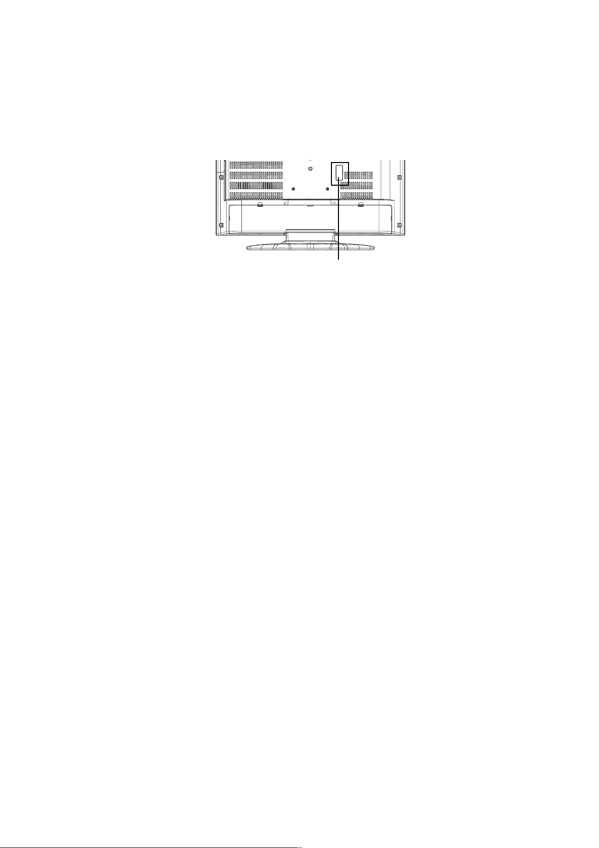
RE-WRITE FOR DIGITAL SOFT FIRMWARE
Prepare the following tools for Up-Date of the Firmware.
1 Computer of WINDOWS2000
2 USB Flash Memory (Use only SanDisk Cruzer Mini USB Flash Drive 256Mb)
SET (REAR)
USB CONNECTOR
NOTE: The operating manual for Re-writing is included in USA HD DTV ROM DISC (JG176).
C-3
Page 23
WHEN REPLACING EEPROM (MEMORY) IC
CONFIRMATION OF CHECK SUM, POWER ON TOTAL HOURS, MICON VERSION AND
DIGITAL TV MICON FIRMWARE
Initial total of MEMORY IC, POWER ON total hours, MICON VERSION and Digital TV MICON Firmware can be checked on
the screen. Total hours are displayed in 16 system of notation.
NOTE:
1.
2.
3.
4.
If you set a factory initialization, the total hours is reset to "0".
Please refer to "CONFIRMATION OF INITIAL DATA" when SUM DATA is not corresponding.
Turn on the POWER, and set to the TV mode.
Set the VOLUME to minimum.
INIT : C7C3
Press both VOL. DOWN button on the set and Channel
button (8) on the remote control for more than 2 seconds.
ROM : 0000
After the confirmation of each check sum, POWER ON
total hours, MICON VERSION and Digital TV MICON
Firmware, turn off the power.
*1 DVP1 is different according to each set.
ADC : 8F97
DVP1 : F5F5 *1
DVP2 : 29EF
Initial setting data check sum.
Rom correction data check sum.
AD CONVERTER data check sum.
SCALER data check sum.
POWER ON total hours.
= (16 x 16 x 16 x thousands digit value)
+ (16 x 16 x hundreds digit value)
+ (16 x tens digit value)
+ (ones digit value)
MICON Version
Digital TV MICON Firmware
LCD ON 0000
OEC7155B_006
DTV d0l63041
FIG. 1
CONFIRMATION OF INITIAL DATA
If a service repair is undertaken where it has been required to change the MEMORY IC, the following steps should be taken to
ensure correct data settings while making reference to INITIAL SETTING TABLE (Attached "INITIAL DATA").
Turn on the POWER, and set to the TV mode.
1.
Set the VOLUME to minimum.
2.
Press both VOL. DOWN button on the set and Channel button (6) on the remote control for more than 2 seconds.
3.
ADDRESS and DATA should appear as FIG 2.
ADDRESS DATA
INIT 0000 00
LCD ON 0000
OEC7155B_006
DTV d0l63041
FIG. 2
ADDRESS is now selected and should "blink". Using the UP/DOWN buton on the remote, step through the ADDRESS
4.
until required ADDRESS to be changed is reached.
Press RIGHT/LEFT button to select DATA. When DATA is selected, it will "blink".
5.
Again, step through the DATA using UP/DOWN button until required DATA value has been selected.
6.
Pressing RIGHT/LEFT button will take you back to ADDRESS for further selection if necessary.
7.
Repeat steps 4 to 6 until all data has been checked.
8.
When satisfied correct DATA has been entered, turn POWER off (return to STANDBY MODE) to finish DATA input.
9.
After the data input, set to the initializing of shipping.
Turn POWER on.
10.
Press both VOL. DOWN button on the set and Channel button (1) on the remote control for more than 2 seconds.
11.
After the finishing of the initializing of shipping, the unit will turn off automatically.
12.
The unit will now have the correct DATA for the new MEMORY IC.
C-4
Page 24
ELECTRICAL ADJUSTMENTS
1. ADJUSTMENT PROCEDURE
Read and perform these adjustments when repairing the
circuits or replacing electrical parts or PCB assemblies.
CAUTION
•
Use an isolation transformer when performing any
service on this chassis.
•
When removing a PCB or related component, after
unfastening or changing a wire, be sure to put the wire
back in its original position.
•
When you exchange IC and Transistor with a heat sink,
apply silicon grease (YG6260M) on the contact section of
the heat sink. Before applying new silicon grease,
remove all the old silicon grease. (Old grease may cause
damage to the IC and Transistor).
Prepare the following measurement tools for electrical
adjustments.
1. Pattern Generator
2. BASIC ADJUSTMENTS
On-Screen Display Adjustment
1.2.Set the VOLUME to minimum.
Press the VOL. DOWN button on the set and the
channel button (9) on the remote control for more than
2 seconds to display adjustment mode on the screen as
shown in Fig. 2-1.
TV
01 H POSI OSD
3.
Use the UP/DOWN button or Channel button (0-9) on
the remote control to select the options shown in
Fig. 2-2.
4.
Press the MENU button on the remote control to end
the adjustments.
5.
To display the adjustment screen for AV, YUV, HDMI
mode, press the INPUT button on the remote control to
set to the AV, YUV, HDMI. To display the adjustment
screen for DVD mode, press the TV/DVD button on the
remote control to set to the DVD. Press the VOL.DOWN
button on the set and the channel (9) on the remote
control for more than 2 seconds.
346
Fig. 2-1
NO.
FUNCTION
NO.
H POSI OSD
01
V POSI OSD
02
R DRIVE (N)
03
R CUTOFF (N)
04
G DRIVE (N)
05
G CUTOFF (N)
06
B DRIVE (N)
07
B CUTOFF (N)
08
R DRIVE (C)
09
R CUTOFF (C)
10
G DRIVE (C)
11
G CUTOFF (C)
12
B DRIVE (C)
13
B CUTOFF (C)
14
R DRIVE (W)
15
R CUTOFF (W)
16
G DRIVE (W)
17
G CUTOFF (W)
18
B DRIVE (W)
19
B CUTOFF (W)
20
FUNCTION
22
H POSI 60Hz
24
V POSI 60Hz
25
BAK LIGHT CENT
26
BAK LIGHT MAX
27
BAK LIGHT MIN
28
BRIGHT CENT
29
BRIGHT MAX
30
BRIGHT MIN
31
TINT
35
CONTRAST CENTER
36
CONTRAST MAX
37
CONTRAST MIN
38
COLOR CENT
39
COLOR MAX
40
COLOR MIN
63
CONTRAST 40
64
BRIGHT (3F54)
65
CONTRAST (3F55)
66
SRC TOP
67
DFEA VIMGVT
Fig. 2-2
2-1: WHITE BALANCE
1.
Place the set in Aging Test for more than 15 minutes.
2.
Receive the gray scale pattern from the Pattern
Generator.
3.
Press the INPUT button on the remote control to set to
the AV mode.
4.
Using the remote control, set the brightness and contrast
to normal position.
5.
Activate the adjustment mode display of Fig. 1-1 and
press the channel button (03) on the remote control to
select “R DRIVE (N)”.
6.
Press the UP/DOWN button on the remote control to
select the “R CUTOFF (N)”, “B DRIVE (N)”, “B CUTOFF
(N)”, “R DRIVE (C)”, “R CUTOFF (C)”, “B DRIVE (C)”, “B
CUTOFF (C)”, “R DRIVE (W)”, “R CUTOFF (W)”, “B
DRIVE (W)” and “B CUTOFF (W)”.
7.
Adjust the RIGHT/LEFT button on the remote control to
whiten the R CUTOFF (N), B DRIVE (N), B CUTOFF (N),
R DRIVE (C), R CUTOFF (C), B DRIVE (C), B CUTOFF
(C), R DRIVE (W), R CUTOFF (W), B DRIVE (W) and B
CUTOFF (W) at each step tone sections equally.
8.
Perform the above adjustments 5 and 6 until the white
color is looked like a white.
D-1
Page 25

ELECTRICAL ADJUSTMENTS
2-2: Confirmation of Fixed Value (Step No.)
Please check if the fixed values of each of the adjustment items are set correctly referring below. (TV/AV/YUV/HD-MI/DVD)
HD-MIYUV
TV 720p
TV
NO. FUNCTION
1 H POSI OSD 346 346 346 346 346 346 346 346 346 346 346 346 346 346
2 V POSI OSD 83 83 83 83 83 83 83 83 83 83 83 83 83 83
5 G DRIVE (N)
6 G CUTOFF (N)
11 G DRIVE (C)
12 G CUTOFF (C)
17 G DRIVE (W)
18 G CUTOFF (W)
22 H POSI 60Hz
22 H POSI (SIDE BAR)
24 V POSI 60Hz
25 BAK LIGHT CENT
26 BAK LIGHT MAX
27 BAK LIGHT MIN
28 BRIGHT CENT
29 BRIGHT MAX
30 BRIGHT MIN
31 TINT
37 CONTRAST MIN(N)
38 COLOR CENT
39 COLOR MAX
40 COLOR MIN
64 BRIGHT (3F54)
65 CONTRAST (3F55)
66 SRC TOP(STRECH)
66 SRC TOP(SIDE BAR)
66 SRC TOP(CINEMA WIDE1)
66 SRC TOP(ZOOM)
66 SRC TOP(S.STRECH)
67 DEFA VIMGVT(STRECH)
67 DEFA VIMGVT(SIDE BAR)
67 DEFA VIMGVT(CINEMA WIDE1)
67 DEFA VIMGVT(ZOOM)
67 DEFA VIMGVT(S.STRECH) 26 25 26 26 26 56 --- --- 26 56 --- --- 55 26
128 128 128 128 128
128 128 128 128 128
128 128 128 128 128
128 128 128 128 128
128 128 128 128 128
128 128 128 128 128
276 320 276 276 276
284 322 284 284 284 140
23 63 23 23 34
128 128 128 128 128
255 255 255 255 255
00 00 00 00 00 00 00 00 00 00 00 00
126 126 126 126 126 126 126 126 126 126 126 126
156 156 156 156 156 156 156 156 156 156 156 156
70 70 70 70 70 70 70 70 70 70 70 70
108 128 109 116 115
50 50 50 50 50 50 50 50 50
75 115 92 94
127 127 127 127
00 00 00 00
--- 128 --- --- ---
--- 180 --- --- --20 20 20 20 20 20 20 20 20 20 20 20 20 20
20 20 20 20 20 20 --- --- 20 20 --- --- 20 20
18 20 18 18 20 20 --- --- 20 20 --- --- 20 18
43 43 43 43 43 43 --- --- 43 43 --- --- 43 43
26 26 26 26 26 26 --- --- 26 26 --- --- 26 26
20 25 20 20 20 43 26 24 20 44 32 24 42 20
20 25 20 20 20 43 --- --- 20 43 --- --- 42 20
20 28 20 20 20 44 --- --- 20 44 --- --- 42 20
50 28 50 50 50 104 --- --- 50 104 --- --- 102 50
AV AV (S) 480i 480p 720p 1080i 480i 480p 720p 1080i VGA DVD
Step No.
128 128 128 128 128 128 128 128 128
128 128 128 128 128 128 128 128 128
128 128 128
128 128 128
128 128 128
128 128 128
134 322 122
...
... 274 140 ... ... 160
34 55 38
128 128 128
255 255 255
122 122 122 122
83 115 115 115
127 127 127 127
00 00 00 00 00 00 00 00 00 00
126 128 128 113 113 113 113 113 --182 180 180 122 122 122 122
128 128 128 128 128
128
128 128 128 128 128
128
128 128 128 128 128
128
128 128 128 128 128
128
266 134 284 228
35 34 54 38
128 128 128 128
255 255 255 255
132 131 132 132 120
50 50 50 50 50
77 77 77 77 77 91
127 127 127 127 127
127
156 276
34 23
128 128
255 255
00 00
126 126
156 156
70 70
122 ---
284
D-2
Page 26
ELECTRICAL ADJUSTMENTS
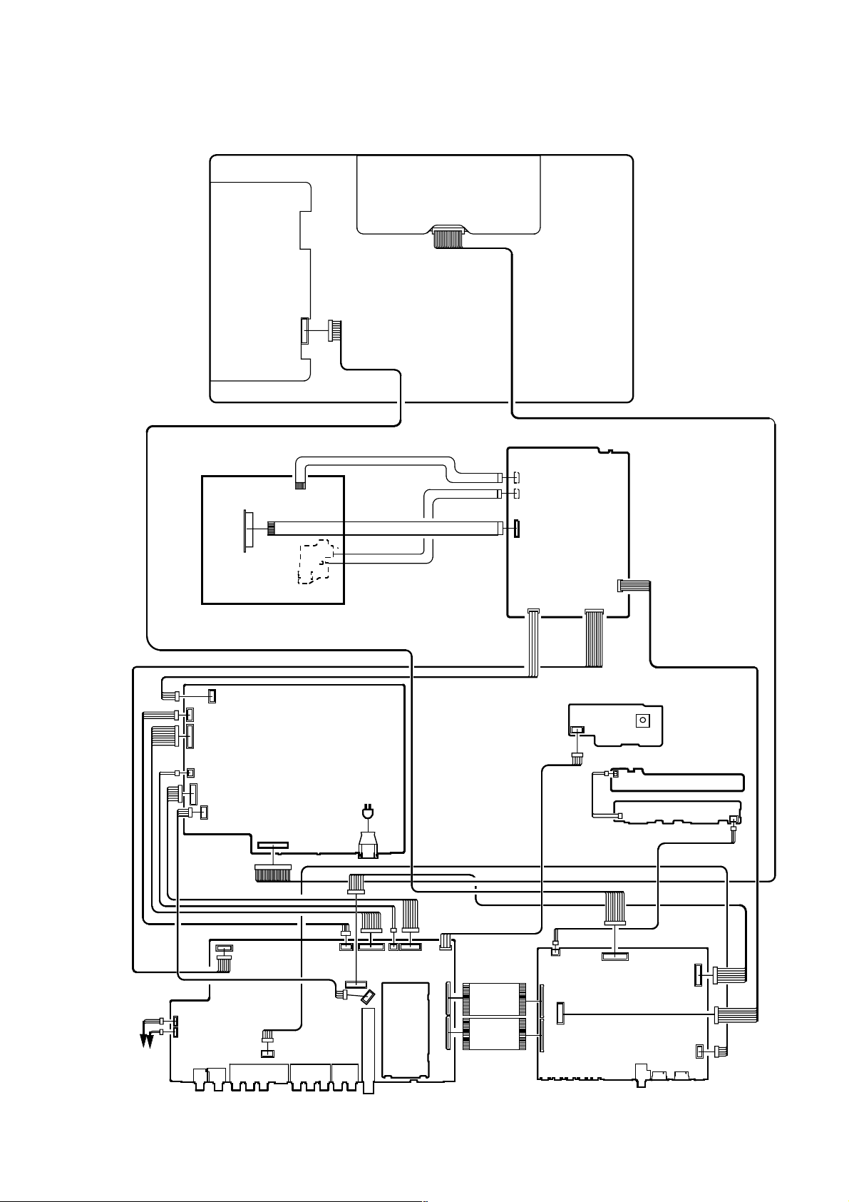
3. ELECTRICAL ADJUSTMENT PARTS LOCATION GUIDE (WIRING CONNECTION)
LCD PANEL
DVD MT PCB
DVD DECK
CP509
CP512
CP511
CP510
CP507
CP508
POWER
PCB
CP506
J502
AC IN
CP2303
CP2302
CP2301
CD501
CD702
CD703
REMOCON PCB
CP2201
OS2200
OPERATION 2 PCB
CP2251
CD2251
OPERATION1 PCB
CP2203
SPEAKER
SPEAKER
CP301
CP303
J4201
J4205
J4202
CP4401
AV PCB
CP901
J4211
CP3801
CP3808
J4204
CP3803
CP3807
TU5801
CP4202
CP3802
CP3804
CP4204
CP4203
DIGITAL PCB
D-3
CD4204
CD4203
CP2200
CP4303
CP802
CP803
SCALER PCB
CP7203
J4301
CP3201
CP3602
CP3601
CP3603
Page 27

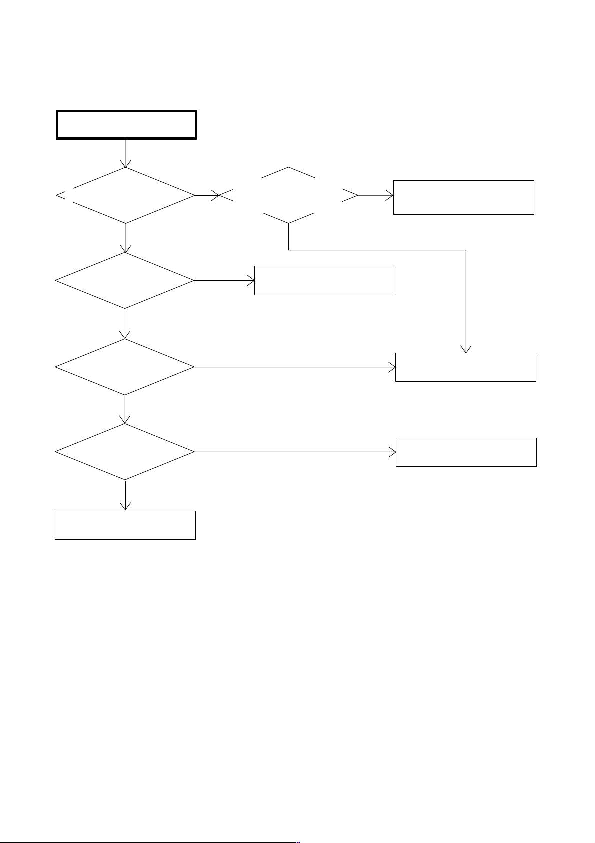
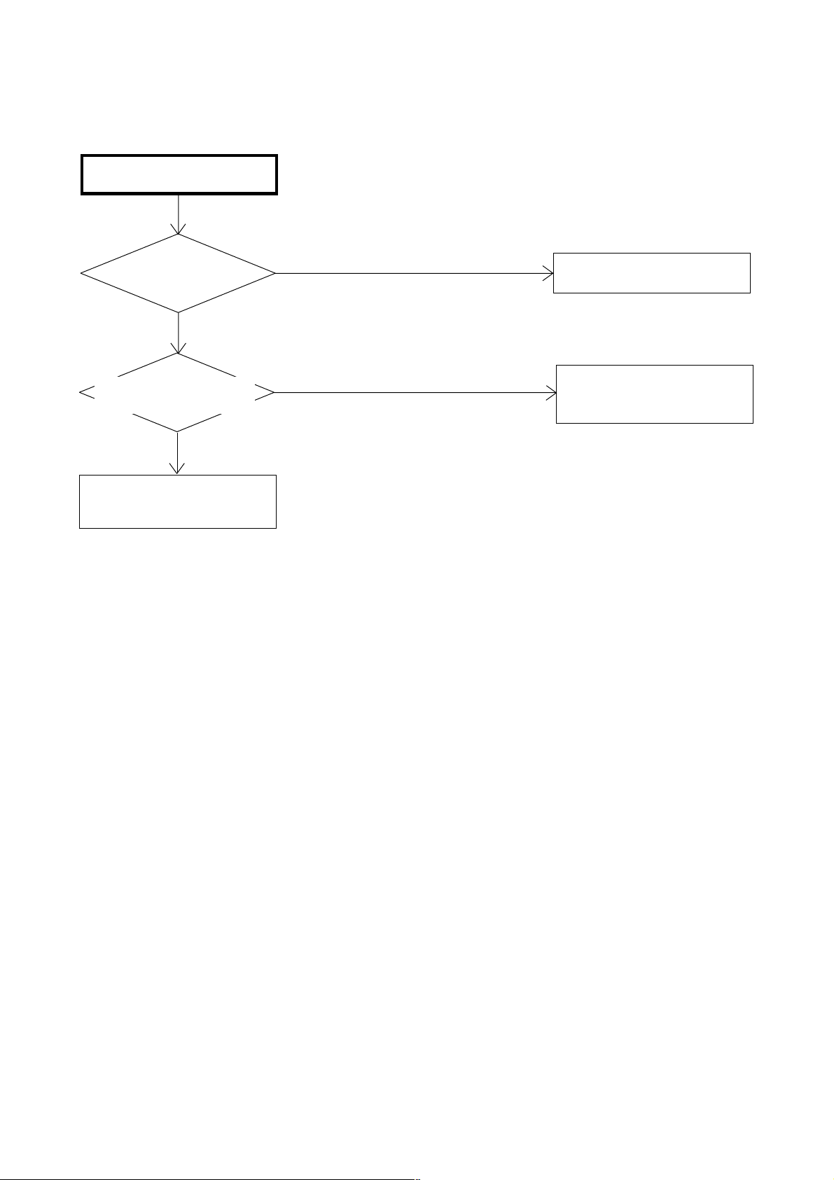
POWER DOES NOT TURN ON
TROUBLESHOOTING GUIDE
IS F501 BROKEN ?
NO
IS THERE VOLTAGE
AT PIN 4 OF IC503
20.5V ?
YES
IS THERE VOLTAGE
AT PIN 4 OF IC506
AT5V ?
YES
IS THERE VOLTAGE
AT PIN 2 OF IC3804
AT3.3V ?
YES
NO
NO
NO
CHANGE F501.
CHECK IC503 AND
PERIPHERAL CIRCUIT.
CHECK IC506 AND
PERIPHERAL CIRCUIT.
OR CHANGE POWER PCB.
CHECK IC3804 AND
PERIPHERAL CIRCUIT.
OR CHANGE AV PCB.
YES
CHANGE SCALER PCB.
E-1
Page 28
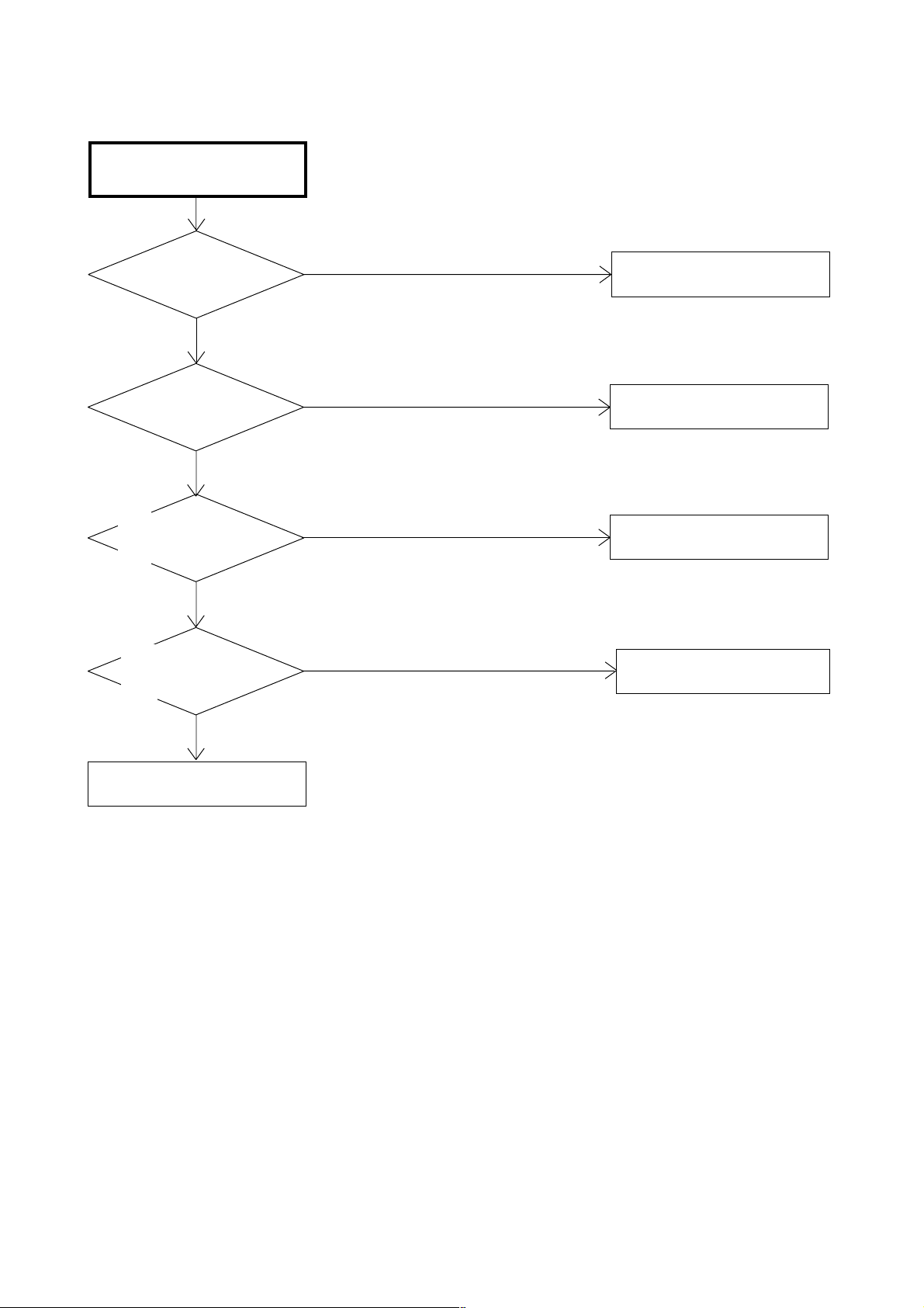
THE PICTURE DOES NOT
APPEAR (1).
TROUBLESHOOTING GUIDE
DOSE BACK LIGHT SHINE ?
YES
IS CD7204 CONNECTED ?
YES
IS THERE SIGNAL
AT CP7204 ?
NO
IS THERE SIGNAL
AT IC7201 ?
NO
NO
YES
NO
IS THERE VOLTAGE AT
PINS 1, 2, 3, 4 AND 5
OF CP503 24V ?
YES
CONNECT CD7204.
NO
CHECK IC502, T502 AND
PERIPHERAL CIRCUIT.
CHANGE V2301.
CHANGE IC7201.
YES
CHECK IC801.
OR CHANGE SCALER PCB.
E-2
Page 29
THE PICTURE DOES NOT
APPEAR (2).
TROUBLESHOOTING GUIDE
IS THERE SIGNAL
AT IC4201 ?
YES
IS CD4203 CONNECTED
AND IS THERE SIGNAL ?
YES
CHECK IC801 AND
PERIPHERAL CIRCUIT.
NO
NO
CHECK IC4201 AND
PERIPHERAL CIRCUIT.
CONNECT CD4203.
CHECK IC4201 AND
PERIPHERAL CIRCUIT.
E-3
Page 30
THE PICTURE APPEARS, BUT
THE AUDIO DOES NOT
APPEAR.
TROUBLESHOOTING GUIDE
IS CD301 AND CD303
CONNECTED ?
YES
IS THERE SIGNAL
CD301 AND CD303 ?
NO
IS THERE SIGNAL
AT PINS 11 AND 15
OF IC301 ?
NO
IS THERE SIGNAL
AT PINS 27 AND 28
OF IC904 ?
NO
YES
YES
NO
CONNECT CD301 AND CD303.
CHANGE SP301 AND SP302.
CHECK IC301 AND
PERIPHERAL CIRCUIT.
CHECK IC904 AND
PERIPHERAL CIRCUIT.
YES
CHANGE AV PCB.
E-4
Page 31

THE STOP PICTURE
"PLEASE WAIT".
TROUBLESHOOTING GUIDE
IS CD3806 CONNECTED ?
YES
IS DIGITAL PCB
CONNECTED ?
YES
IS THERE VOLTAGE
AT PINS 1 AND 2 OF
CD3806 5V ?
YES
CHANGE DIGITAL PCB.
NO
NO
NO
CONNECT CD3806.
CONNECT DIGITAL PCB.
CHECK Q512, IC509 AND
PERIPHERAL CIRCUIT.
E-5
Page 32

THE COLOR DOES NOT
APPEAR.
TROUBLESHOOTING GUIDE
IS SETTING OF
COLOR NORMAL ?
YES
IS THE COLOR
SIGNAL RECEIVED ?
YES
IS THERE SIGNAL
AT IC801 ?
YES
IS THERE SIGNAL
AT IC7201 ?
NO
NO
NO
NO
CHANGE THE SETTING OF
COLOR.
RECEIVE THE COLOR SIGNAL.
CHECK IC801 AND
PERIPHERAL CIRUCUIT.
CHECK IC7201 AND
PERIPHERAL CIRUCUIT.
YES
CHANGE SCALER PCB.
E-6
Page 33

ON SCREEN DISPLAY DOES
NOT APPEAR.
TROUBLESHOOTING GUIDE
IS THERE SIGNAL AT
PINS 2, 3, 4 AND 5 OF
IC101 ?
YES
IS THE COLOR SIGNAL
AT PINS 57, 58, 59 AND
60 OF IC801 ?
YES
CHANGE SCALER PCB.
NO
NO
CHECK IC101 AND
PERIPHERAL CIRCUIT.
CHECK IC801AND
PERIPHERAL CIRCUIT.
E-7
Page 34

(DVD SECTION)
DOES NOT DISPLAY
DVD PICTURE
TROUBLESHOOTING GUIDE
DOES THIS DISPLAY
LOGO PICTURE ?
NO
DOES THIS HAVE SIGNAL
AT PINS 151 AND 153 OF
IC4001 ?
NO
DOES IC4001 GETS
P.CON+3.3V AND
P.CON+1.8V ?
NO
CHECK P.CON+3.3V AND
P.CON+1.8V LINE.
YES
YES
YES
CHECK THE DISC.
CHECK PINS 9 AND 7 OF
CD703 AND PERIPHERAL
CIRCUIT.
CHANGE IC4001.
E-8
Page 35

DISC DOES NOT EJECT.
TROUBLESHOOTING GUIDE
DOES OSD APPEAR
ON THE SCREEN ?
YES
DOES THIS EJECT
DISC AT CHANGE
DVD DECK ?
YES
CHANGE DVD DECK.
NO
NO
IS REMOTE KEY SET
EFFECTIVELY ?
YES
CHECK PINS 205 AND 206 OF
IC4001 AND PERIPHERAL
CIRCUIT.
DOES THIS HAVE
SIGNAL AT PINS 4
AND 5 OF CP2302 ?
YES
DOES THIS HAVE
SIGNAL AT PINS 1
AND 2 OF CP2302 ?
NO
NO
NO
CHECK PINS 29 AND 30 OF
IC101 AND PERIPHERAL
CIRCUIT.
CHECK IC2301 AND
PERIPHERAL CIRCUIT.
CHANGE IC2301.
YES
CHANGE IC4001.
E-9
Page 36

DOSE NOT PLAY DVD.
TROUBLESHOOTING GUIDE
CHANGE DVD DECK.
NO
DOES THIS DISPLAY
"INCORRECT DISC".
NO
DOES THIS DISPLAY
READING MARK ?
YES
DOES DISC ROTATE ?
YES
YES
NO
NO
DOES CD2001
CONNECT WITH CP2301
CORRECTLY ?
NO
CONNECT CD2301.
CHANGE IC4001.
CHANGE DVD DECK.
YES
IS THEVOLTAGE
BETWEEN JG017 AND
JG018 LESS THAN 0.6V ?
YES
CHANGE IC4001.
E-10
Page 37

DOES NOT PLAY CD.
TROUBLESHOOTING GUIDE
CHANGE DVD DECK.
NO
DOES THIS DISPLAY
"INCORRECT DISC".
NO
DOES THIS DISPLAY
READING MARK ?
YES
DOES DISC ROTATE ?
YES
YES
NO
NO
DOES CD2001
CONNECT WITH CP2301
CORRECTLY ?
NO
CONNECT CD2301.
CHANGE IC4001.
CHANGE DVD DECK.
YES
IS THE VOLTAGE
BETWEEN JG019 AND
JG018 LESS THAN 0.6V ?
YES
CHANGE IC4001.
E-11
Page 38

NO SOUND DVD/CD
ANALOG AUDIO.
TROUBLESHOOTING GUIDE
DOES THIS HAVE
SIGNAL AT PINS 3 AND
5 OF CD703 ?
NO
DOES THIS HAVE
SIGNAL AT PINS 7 AND
8 OF IC8502 ?
NO
DOES THIS HAVE SIGNAL
AT PINS 113, 115, 116
AND 118 OF IC4001 ?
NO
CHANGE IC4001.
YES
YES
YES
REFER TO "LCD SECTION".
CHECK PINS 7 AND 8 OF
IC8502 AND PERIPHERAL
CIRCUIT.
CHANGE IC8502.
NO SOUND DVD/CD
DIGITAL AUDIO.
DOES THIS HAVE
SIGNAL AT PIN 1 OF
CD703 ?
NO
DOES THIS HAVE
SIGNAL AT PIN 110
OF IC4001 ?
NO
CHANGE IC4001.
YES
YES
CHECK J4202 AND
PERIPHERAL CIRCUIT.
CHECK IC4001 AND
PERIPHERAL CIRCUIT.
E-12
Page 39

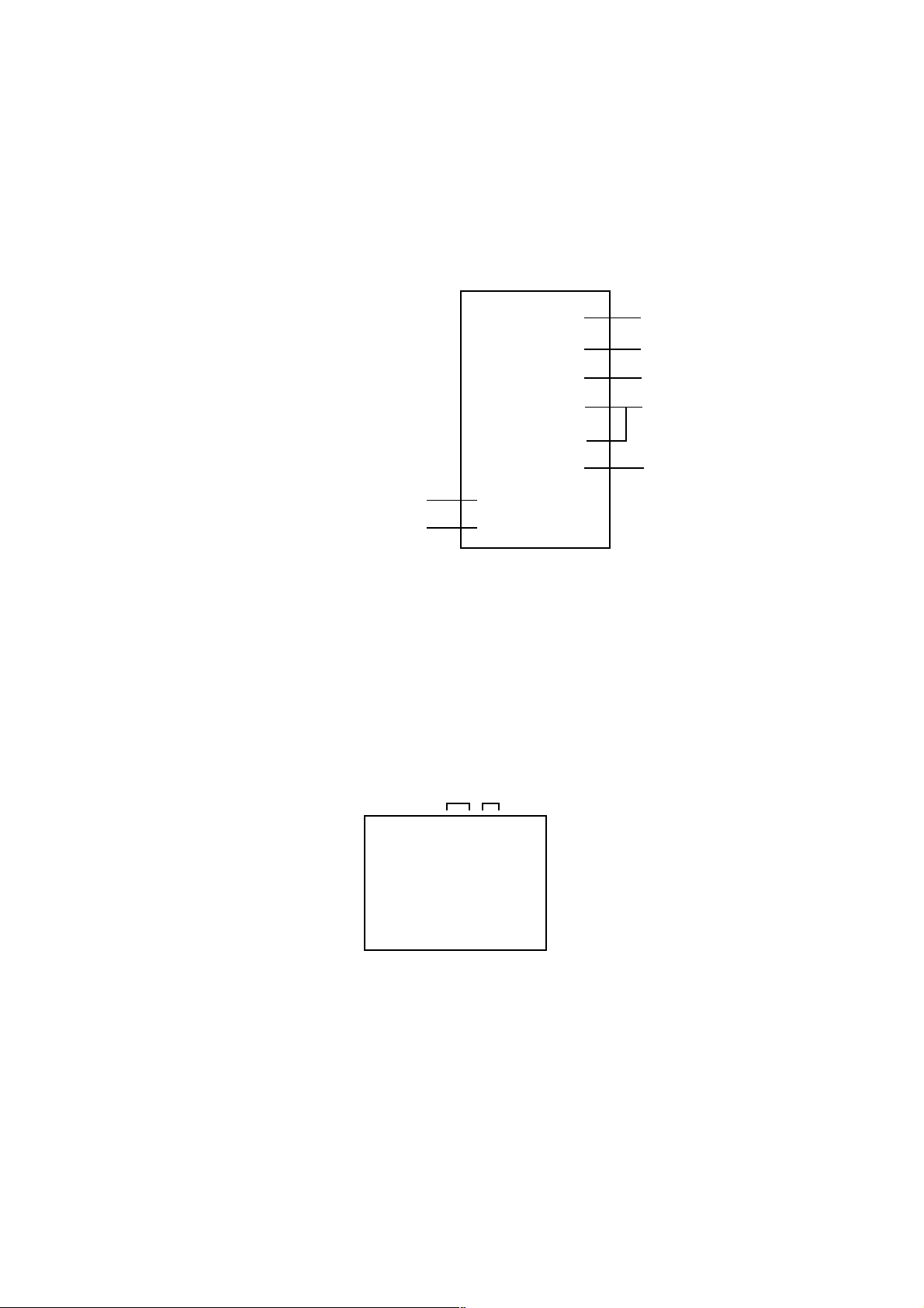
DVD BLOCK DIAGRAM
DVD LOADER
DSM2
OPU
SPINDLE/
STEPING/
SLED
MOTOR
E
DVD/CDPD
RF_A, B, C, D, E, F
DVD/CD, DVD_LD, CD_LD
TR+/-, FO+/-,
MOT_LD+/-,
MOT_SLED+/-,
MOT_SPDL+/-
HOME, TIN_SW, TOUT_SW
Motor Drive
IC2301
LA6565VR
HA0~A20,
HD0~D15,
MEMCS0, RD, WR
SPINDLE/SLED/
FOCUS/TRACK_PWM,
TRAY_CLOSE/OPEN
ADCIN_5, 6, 7
A
MPEG/MICON/DSP/RF_AMP
IC4001
ZR36862PQCG-B
C, D
ML, MC, MD,
AMCLK, ABCLK,
ALRCLK, ASDATA0
STEREO DAC
IC8502
PCM1753DBQR
B
LCD BLOCK
TX
RX
START_SW
SPDIF
DVD C
DVD Y
DVD RESET
DVD POWER
ZERO
AUDIO L
AUDIO R
FLASH 16M
C
SST39VF1601-70-4C-EKE
IC4007
SD_A0~A10
SD_D0~D15
M12L16161A-7TG
RAMDQM, CLK, CKE, WE#, CAS#,
RAS#, CS0#, CS1#, SD_BA0
16M SDRAM
IC4009
C
A---P.CON+6V
B---P.CON+5V
C---P.CON+3.3V
D---P.CON+1.8V
E---P.CON+A5V
F-1
F-2
Page 40

SCALER/LVDS/MICON/ADC/JACK/AV SWITCH1/REGULATOR BLOCK DIAGRAM
INTERFACE
AV SWITCH2/
STEREO/
SOUND AMP
DVD
DIGITAL RGB
DDVS
DDHS
SW_CVBS
SW_Y
SW_C
SW VIDEO_Y
SCART1_B_IN
SCART1_G_IN
SCART1_R_IN
AUDIO_MUTE
SCL
SDA
DVD_RESET
DVD_RX
A/D CONVERTER
IC2101
MST9883C-LF-110
DIGITAL
24bit RGB
D_CLK, D_EN,
D_HS, D_VS
56
57
58
27
28
78
30
29DVD_TX
58
27
28
42
74
90 17 89
SCALER
IC801
R8J66604A72FP
57
2
MICON
IC101
OEC7155A
10 14
1
DIGITAL
24bit RGB
D_CLK, D_EN,
D_HS, D_VS
84
X801
54MHz
85
60
4SI_SDA_IN/4SI_SCL
4SI_CHIP_SE/4SI_SDA_OUT
5
54
54
53
33 34
LVDS IC
IC7202
DTC34LM85AL
EEPROM IC 256K
AT24C256N-10 SU-2.7
AT24C256N-10 SU-2.7
IC103
6
EEP_SCL
5
EEP_SDA
EEPROM IC 256K
IC104
6
EEP_SCL
5
EEP_SDA
TX OUT0~3+
TX OUT0~3TXCLKOUT+
TXCLKOUT-
POWR_ON-H
LCD PANEL
V2301
V320B1-L01
TUNER/DIGITAL/
POWER
PSU_5VD
LCD_H
POWER_FAIL
LCD_ON
AT+3.3V
P.CON+3.8V
SCART2 OUT CVBS SW
P.CON+3.3V REG
IC3201
BA00BC0WFP
P.CON+1.5V REG
IC3202
BD7820FP
6
2
4
IC8103
MM150XNRE
2
2
6
6 1
1 4
DTUNER RX
DTUNER TX
Q8101, Q8102
Q8103
SYNC_SEPA
SYSTEM RESET
IC102
1
2
D105
P.CON+3.3V
4
P.CON+1.5V
PST3229NR
RESET
SCALER_H
1 2 3
AUDIO AMP
IC4406
NJM4580M
6
7
5
Q4405
Q4404, Q4407,
Q4408
Q4406
MUTE SW
MUTE SW
MUTE SW
DVD_AUDIO_OUT_R
DVD_AUDIO_OUT_L
ZERO
DVD_AUDIO_R
DVD_AUDIO_L
TUNER/DIGITAL/
POWER
DVD
F-3
F-4
Page 41

AV SWITCH2/STEREO/SOUND AMP BLOCK DIAGRAM
SCALER/LVDS/
MICON/ADC/JACK/
AV SWITCH1/
REGULATOR
TUNER/DIGITAL/
POWER
SW_CVBS
SW_Y
SW_C
V_OUT
SIF_OUT
AV SW
IC4201 AN15853B-E1
24
SDA
SCL
25
SW_A_IN_R
28
30
SW_A_IN_L
31
SW_CVBS
SW_Y
33
35
SW_C
16
TUNER_V
V1-V
V1-Y
V1-C
V1-L
VL-R
V1-L
VL-R
V2-V
V2-R
V2-L
20
22
12
10
INPUT 1/2
J4205 SAV-12CP-01Z5
2
4
6
3
5
9
14
3
4
17
20
9
10
15
18
22
AUDIO_IN 4/5
J4204 AV2-67A03-01
2
5
INTERFACE
SCALER/LVDS/
MICON/ADC/JACK/
AV SWITCH 1/
REGULATOR
MICON2
TUNER/DIGITAL/
POWER
AUDIO_MUTE
CP901
4
HDMI_I2SS
HDMI_I2SSDO
3
HDMI_I2SWS
2
DVD
SW_A_L
SW_A_R
SCL
SDA
SPDIF
SOUND+B
COAXIAL
J4206
2
2
3
AUDIO_OUT_JACK
J4201
STEREO
IC904 MSP4440G-QA-C13-100
67
ANA_IN1+
SC1_IN_L
56
SC1_IN_R
57
SC2_IN_L53
54
SC2_IN_R
2
I2C_CL
3
I2C_DA
36
VARIOUT_R
37
VARIOUT_L
4
I2S_CL
I2S_DA_IN
7
I2S_WS
5
AV2_IN_L
AV2_IN_R
XTAL_IN
XTAL_OUT
SPOUT_R
SPOUT_L
50
51
18.432MHz
71
72
27
28
X901
COMPONENT
IC4401
NJM2584AM(TE1)
5
1
14
9
SOUND AMP IC
IC301 TA2024-ASE
11
INV2
15
INV1
33
VDDA
VDD1
30
12
MUTE
VDD1
29
VDD2
26
25 VDD2
6
8
11
16
3
OUTP1
OUTM1
OUTM2
OUTP2
31
27
24
28
CS_IN 4
J4211 AV3-67A02-01H
2
4
6
SCART1_R_IN
SCART1_G_IN
SCART1_B_IN
DTUNER_V
DTUNER_U
DTUNER_Y
SPEAKER
SP301
SPEAKER
SP302
SCALER/LVDS/
MICON/ADC/JACK/
AV SWITCH1/
REGULATOR
TUNER/DIGITAL/
POWER
F-5 F-6
Page 42

TUNER/DIGITAL/POWER BLOCK DIAGRAM
TU5801
EEP ROM
IC2404
BR24L64-WE2
+3.3V
X2401
55.474MHz
X2402
25.140MHz
I2CDATA
I2CCLKA
256Mbit DDR SDRAM
IC2402
HY5DU561622ETP-D43
DQA
AA
CLKAB
ATSC/CLER CABLE ASIC
FAD
FLASH MEMORY
IC2406
HY27US0828IA-TP
+3.3V
256Mbit DDR SDRAM
DQA
IC2403
CLKAB
HY5DU561622ETP-D43
IC2401
X240H
AA
+1.2V
+3.3V
+1.8V
+2.6V
Y OUT
U OUT
V OUT
TUNER SCL
TUNER SDA
T_FAT_IFP
T_FAT_IFN
DC/DC CTL
1
IC3401
AL1042
REG 1.8V
4 2
BD7820FP
UNREG 5V
9
REG 3.3V
IC3402
4 2
BA00BCWEP
IC3403
UNREG 4V
REG 2.6V
IC3404
4
BA7810HFP
UNREG 5V
2
UNREG 4V
+5V
+32V
4 7 9
+5V
SDA
10
SCL
V_OUT
13
14 152
+5V
SIF
IF_OUT1
19
20
IF_OUT2
DTUNER Y
DTUNER U
DTUNER V
V_OUT
SIF_OUT
DTUNER RX
DTUNER TX
AV SWITCH2/
STEREO/
SOUND AMP
SCALER/LVDS/
MICON/ADC/JACK/
AV SWITCH1/
REGULATOR
CP3801
1
2
CP3803
1
2
3
7
8
CP3802
1
CP3804
1
2
3
5
6
SCALER/LVDS/
MICON/ADC/JACK/
AV SWITCH1/
REGULATOR
SOUND+B
SOUND+B
5VSC
5VSC
5VSC
12VSC
12VSC
9VSC
POWER FAIL
LDC_H
AT+5V
BACKLIGHT ON
LIGHT_CTL
PSU_5VD
LVD_ON
LCD_H
POWER_FAIL
3.3V CONTROL
IC3801
AL1010
1
AV SWITCH2/
SOUND+B
AT+3.3V REG
IC3804
1
3
P.CON32V REG
IC3805
LA7995M-TLM
CHOPPER
IC3802
RSS050P03
7
4
5
14
7
PQ070XF01SZH
2
AT+3.3V
AT+5V
P.CON+12V
P.CON+3.8V
P.CON+9V
STEREO/
SOUND AMP
F-8F-7
Page 43

INTERFACE BLOCK DIAGRAM
HDMI
CONNECTOR
CP3601
19 DET
18
POWER
17
GND
16
SDA
15
SCL
CLK-
12
10
CLK+
9D0-
D0+
7
D1-
6
D1+
4
D2-
3
1
D2+
EEP_ROM
IC3601 BR24L02F-WE2
5
SDA
6
SCL
7
WP
8
VCC
HDMI Port Protection
IC3605 CM2021-00TR
DDC_DAT_OUT
21
DDC_CLK_OUT
22
GND
A2
A1
A0
4
3
2
1
DDC_DAT_IN
DDC_CLK_IN
18
17
HDMI INTERFACE
IC3603 SiI9011CLU
DSDA
39
DSCL
40
50
RXC-
51
RXC+
RX0-
54
55
RX0+
RX1-
58
59
RX1+
62
RX2-
RX2+
63
QE19
QE18
QE16
QE15
QE12
QE11
QE8
QE7
QE4
QE3
QE0
ODCLK
HSYNC
VSYNC
SCK
WS
SD0
PVCC
IOVCC
IOVCC
IOVCC
IOVCC
IOVCC
IOVCC
IOVCC
IOVCC
CSCL
CSDA
INT
CVCC18
CVCC18
CVCC18
CVCC18
DVCC18
CVCC18
AVDPVCC18
CVCC18
CVCC18
96
99
101
102
105
108
111
114
117
121
124
119
128
1
76
75
74
47
7
19
31
68
77
98
107
120
40
41
91
12
24
36
45
66
81
82
112
125
3.3VREG
IC3602 BA00BCWFP
IN
GND
OUT
2
1
3
1.8VREG
IC3600 KIA78D33F
IN
GND
2
1
3
OUT
AUDIO_IN
J4301
2
4
DIGITAL RGB
DDCK
DDHS
SW_A_R
SW_A_L
V_SYNC
SCK
WS
SDO
CSCL
CSDA
H_INT
SCALER/LVDS/
MICON/ADC/JACK/
AV SWITCH1/
REGULATOR
AV SWITCH2/
STEREO/
SOUND AMP
MICON2
F-9
F-10
Page 44

RXT_RST#
H_INT
MICON2 BLOCK DIAGRAM
HDMI MICON IC
IC3611
SST89E58RD2-40-C-TQJE(HD101)
36
RX1_RST
8
RX1_INT
VCC
38
X1
X2
14
15
X3601
11.0592MHz
INTERFACE
CSDA
CSCL
SDO
SCK
WS
Q3606
BUFFER
Q3605
BUFFER
EEP ROM IC
IC3608
BR24L32F-WE2
A0
1
A1
2
A2
3
GND
4
VCC
WP
SCL
SDA
29
3
EA-/VPP
CSDA
V-SYNC
41
Q3620
LEVEL SHIFT
V_SYNC
INTERFACE
8
7
6
2
CSCL
5
F-11
AV SWITCH2/
STEREO/
SOUND AMP
CP3602
4
HDMI_I2SS
3
HDMI_I2SSDO
2
HDMI_I2SWS
F-12
Page 45

POWER BLOCK DIAGRAM
AC IN
F501
RELAY
RY501
L506
1
3
P.CON+5V
2
4
4
1 2
L507
RY501
3
POWER SW CTL
1
3
2
4
D507
C510
POWER SW CTL
IC503 STR-W6735
DS
Vcc
FB
2
1
4
6
IC502 STR-X6737
DS
Vcc
FB
2
41
6
TRANSFORMER
T501
8
5
2
1
11
12
13
14
15
16
TRANSFORMER
T502
4
1
8
7
FEED BACK
PS2561AL1-1-V(W)
10
11
14
15
IC512
4
3
1
2
5V REGULATOR
IC506
BA00BC0WCP-V5E2
2 4
3
REGULATOR
IC504 KIA431A-AT
2
1
3
Q504
SW
+24V(INVERTER)
SOUND+B
P.CON+12V
POWER FAIL
FEED BACK
IC511
PS2561AL1-1-V(W)
4
3
1
2
REGULATOR
IC501 KIA431A-AT
2
1
3
9V_REGULATOR
IC510 PQ090RDA1SZH
3
1
2
4
5V_REGULATOR
IC508 LA5774-E
2
1
5V_REGULATOR
IC505 BA7810T-V5
3
2
1
AT+5V
P.CON-H
P.OCN+9V
4
LCD-H
P.CON+5V_LCD
3
4
P.CON+5V
F-13
F-14
Page 46

PRINTED CIRCUIT BOARDS
SH4302
CP7203
Q105 Q101
R151
C116
C4372
CP2200
C4378
IC104
D4301
D4302
SCALER (TOP SIDE)
CP3604CP3201
R3652
R3653
W949
C3646
R3641
W957
X801
IC801
1
CP4303
C861R825R830
C857
C3649 C3648
C3654
C3637
Q3606
IC3608
R3640
NR801
C810
C858
55
1
W886
61
IC2101
IC3201
Q3605
W888
C2130
C3217
C3655
R3637
R3639
D802 D803
R8101
C7241
C7242
C850C856
D805
C834
C832
C830
C883
C2802_1
C2133
C2139
R2109
C2103C2121 C2127
CP803
C7240
C876
C859
C815
C7239
C2149
C2142
R8102
R3621
R3620
C7238
Q2101
B3209
NR802NR803 NR804 NR805NR806NR807
C2106
C131
R163
C109
W875
1
12
D3613
X3601
B804
R833
C892
C7208
L2103
C139
R112
W824
R3633
109
163
C891
C128
D109
Q3600
R3648
C3642
C3643
R3634
C3656
C3647
IC3611
C868
NR2101
NR2102
NR2103
NR2104
C3213
R3632
R3654
34
23
W905
C863 C860
D4310
C801
R3649
NR2105 NR2106
21 41
W873
B3201
B3202
R3223
C7220
C7217
NR7202
NR7201
C7205
C7203
R123 R122
IC101
C101
CP102
W860
C7219
C125
W820
Q3205
C7215
R7201
R145
B3203
C898
C7213
IC7201
W829
C7204
R135
R146
R129
26
1
C7207
IC102
R147
R118
C3209
R3645
CEF170A
C7206
C7210
C2801_1
C7209
C136
D105
R115
W885
C110
CP103
C3641
B801
R114
R197
R149
D3609
X101
C3202
W969
W970
R3631
R3628
R3619
CP802
B3207
B3206
C7224
B7201
W811
C7212
R7203
R7202
R188
R189
W855
W834
IC103
R134 R119
R142R141
R120
51
C117
76
R159
CP101
NR3602NR3607
NR3608
NR3606
NR3605
NR3604
R2112
R2114
D3207D3206
IC3202
R3617
B3610
R8103
1
C8151
CP3602
X3602
R3670
C3630
C8131
L8105
C8149
R3612
IC3603
C3628
C8150
R3630
6597
33
R4313
C4362
NR3601
C3620
L4306
C4324
C3604
B4308
SH4303
B3603
D3602
R3605
R3604
R3606
R4314
C4366
C3603
IC3605
R3602
C3658
C3618
C3657
SH4301
C3601
B4307
IC3601
J4301
CP3601
C3602
R3603
W901
B3604
D3601
W822
D3603
R3608
R3601
R4320
R4319
R4328
W891
W892
C3617
C3613
C3616
C3615
R3607
Q4302
C4315
R4333
C3610
R3609
C4314
R4329
Q4305
R4324
R8116
L8102
R8148
R8145
C3622
B3602
C3606
C3614
C3612
C3621
R8119
C8137
C8144
R8128
C8147
B3605
B3601
C3623
R8113
C8128
Q8101
R8146
R8143
SCALER (BOTTOM SIDE)
W868
B3606
W839
C3605 C3607
R3679
C3627
C3626
C3624
C3609
C3631
C3629
C3625
IC8103
R8123
R8125
C8146
Q8102
W845 W844
B3612
B3615
Q8103
R8131
R8129
R8130
Q8105Q8106
R3678
C3634
C3632
C3636
C3633
C3635
C8113
C8110
C8109
C8112C8129
D3209
C3619
C3608
C3611
C2151
C2150
B3614
C3216
R3237
R3222
R3627
R3626
W883 W809
W803
R808
W930
W929
W805
W931
L2107
C2148
C2146
L2101
W861
W821
R3600
W801
W802
L2106
R2110
C3215
C3223
R3221
C3653
IC3600
C835
R2111
C2144
R3220
W862
R3623
C3650
C3600
C820
C827
C819
W807
C818
C817
C826
C812 C816
C823C814
C837 C836C838
C824
C822
B802
C2145
C2143
C2140
R3625
R3624
C2129
C2126
D3606D3600
R3622
R805
C852
C849
R806
C845
C843
C841 C840
C851
C2125
C2136
C2131C2137
R2108
C2124
C2120
C3652
IC3602
R804
C2132
C2138
R2103
C3651
C3638
C855
R807
C846
C847
C844
C842
C839
C853
R2104
R2116
C2116
L2102
C3645
R3644
R3643
C3640
C3639
B2101
R2117
R2102
R3209
C3212
R3238
R3212
R3629
NR809
C2110
C2105
C2112
C2113
C862
R823
R817R818
B803
W810
C2108
C2111
C3211
R3211
R845
R844
C2109
R819R820
R831
C870
R826
R821
C871
W843
R8104
R8105
C872
R828
R822
R3647
C887
C888
C884
C879
R829
C877C873
C875
C813
C894
C889
C893
C878
B805
C897
R836
C821
C895
C886
R846
D808
R835
R834
C896
L7203
C111C114
R178
R157
R156
R154
C3207
C3206
C3204
W837
C3218
C3219
R3228
R3234
CEF170A
L7202
R116
R117
D807
C118
R160 R161
R199
C107
R200
R155
Q3210
R3242
Q3209
R111
R109
R107
C113
R106
R105
C126
R138
C3205
Q3206
R140
R103
R104
R3235
W867
C7202
L7201
C104
B3208
C3203
C3201
R3224
D101
R102
C7201
C106
R175
R158
R165
R153
C123
D106
R136
R131
R193
R192
R137
C7228NR808
R194
R195
W897
W832
R181
Q106
Q104
G-1 G-2
Page 47

PRINTED CIRCUIT BOARDS
C2313
C2303
R2303
C2318
CP2303
CP2302
R2304
C2302
C2329_1
CP2301_1
C2328_1
C3016_1
D3001
Q3007
R2330
R2337R2325
R2327
R2360
C2331
C3019_1
L3001
DVD MT/OPERATION 2 (TOP SIDE)
DEF092A
R2319
D2304
D2303
W861
R2324
R2334
R2326
R2307
C2346_1
C2341_1
C3032
R2349 R2352
R2342
R2350
R2353
R2328
C2307
IC2301
R2321
R2320
R2335
R2305
C4070
B4009
R4089
C4001
R2332
Q2301
R2340
Q2302
IC3003
C3011
C3001
L3004
CD501
R4062
R4060
R4061
R4063
R4087
C2316_1
C2327_1
C2340_1
C2314_1
R2301
C4096
C4032
C3002
C2310_1
R2338
R2308
C4033
R4078
C4068
R3008
C3007
D4008
C4088
R4052
W809
R2333
C3005
C3006
IC3001
C3008
D3002
Q3008
C4085
R4065
R4003
R4002
L3003
R4005
R4004
R4032
C4069_1
157
1
C4008
C4039
C3018
X4001
R4086
C3023_1
L3002
C4081
R4041
C4071_1
IC3002
C3020
D8509
R4019
C4079
C4028
W860
C8521_1
R4020
R4021
C4029
IC4001
IC8502
R4024
C4076
B4002
C3022_1
C3015
C4098
R4025
C4031
D3003
R8513
R8512
R4026
R4027
IC4007
C8519_1
R4058
B4010
105
53
C4016
B4007
C4095
C8508
C8523
B8503
C4017
C4063_1
SW2253_2SW2252_2SW2255_2SW2254_2SW2251_2
R4071
R4008
L8503
C4045_1
C4046_1
C4047_1
C4064
C4062
W854
C8522
W826
CD703
C4078_1
C4067_1
C8505
C4050_1
C4052_1
C4083_1
R4040
B4005
L8502
W847
DMF066A
IC4009
R4048_1
C4009_1
C4011_1
C4105
R4054 R4053
W817
W827
C4040_1
C4041_1
C4099
B4008
W824
CP2251
C4091
CD702
SH8501
DVD MT/OPERATION 2 (BOTTOM SIDE)
DEF092A
R2253
R2254
R2251
C4012
B4006
R2252
R4036
R4037
R4038
R4039
C4038
DMF066A
R4064
R4059
C4077
C4082
C4072
C8506 C8509
W818
W819
C4026
R4014
C4019
C4018
C8520
C4025
C4024
C4023
W810
C4022
B4004
C4020
C4014
D4005
B3001
C8507C8504
D8510
C4013
C4010
B4015
C3021
W842
R4072
R4018
R4023
R4045
C3024
C4027
C4030
R2255
B4001
R4016
C4034
C4035
R4042
R4051
W840
D4002
D4003
R3027R3029
W822
R4012
C4086
B4018
R4022
R4043
W836
C4007
B4014
C4002
B4016
R4001
C4004
W859
B2304
B2305
R3007
C3004
R3012
C3009
R3020
C2306
R4067
R2339
R3006
R3011
Q3006 Q3005
C2326
R3004
R3005
R3026
R3025
R3024
R3009
C3014
R3010
R3022
R3021
R3023
R2336
R2318
Q3002
C2365
R2302
C2350
R3002
C2301
C4075
B4003
R2306
R2341
R3003
R3001
C3025
R2313
C4057
C4056
C4003
R2309
Q3001
R2310
R3019
R2323
R2329
C2358
C2347
C3017
C2360
C2359
R2357
B4013
B4012
B4011
R3018
C3012
F3001
C2357
C2305
R2358
R2355
C2332
C2348
C2304
W843
C2309
C2317
R2347
R3013
R3014
R2346
R3016
R3015
R2361
R2322
R2348
Q2304
B2301B2302
Q2305
R2359
R2356
Q2303
Q3003 Q3004
G-3 G-4
Page 48

CP303CP301
R320
SH4205
L302
L300
R321
L301
CEF209A
L303
C340_1C342_1
C337
W837
C339
C341
C4431
CMF090A
W884
W822
CP4401
C4459
R4447
C4446
Q4408
Q4209 Q4207
IC4405
Q4406
R4425
Q4404
R4427
SH4204
HS300
IC301
R4208
C4266
C4444
C4441
R4439
R4232
R4458
R4457
R4428
C4429
R4229
R4207
C4421
R4442
Q4407
R4206
C4430
R4426
Q4202
C4443
Q4405
R4456
C4438
IC4406
C4433
C4427
C323
C332
R319
R318
C331
R317
C326
C328
R4443
R4440
C4434
C324
C4447
R4438
C4432
W911
C4461
C4439
W910
C4237
L4218
W807
L4201
L4219
W804
R4236
R4235
L4214
C3825
L903
W893
W894
L904
L4212
W892
L3809
X901
CP901
C3826
C953
C955
C933
R905
C951
R906
C948
D4207
C952
C949
C950
C941
L3807
C3820
C320
C946
R901
W845
1
R903
C916
R902
D4206
C930
PRINTED CIRCUIT BOARDS
AV (TOP SIDE)
L3806
C3818
IC904
C919
C929
C922
C4297
B4215
R4252
R324
D3802
SH4203
C927
4165
25
B4216
W857
W856
C914
C962
C4296
R4254
D3801
L901
C918
C963
C3810
B3801
D3804
R4261
C915
R3811
C319
C3801
C906
C3802
R4459
R4209
C4229_1
IC3804
C3827
C4215
R4212
C4242
C4218
C4207
C4246
C4224
C4206
L4202
C4247
C4222
C4223
C4214_1
C4217
L4213
L3810
C4227
C4203
IC4201
C4205
L4215
L3802
C4220
C4243
C4233
CP3801
C4219
W878
C4262
C4259
D4210
C4251
C4416
D4208
C4250
L5801
C4209
C4415
L5804
CP3807
C3852
C3803
L5802
C4232
C5824
L3803
C5806
L3801
C3850
W851
W914
W915
C3805
CP3808
TU5801
L3804
R5817
R5807
R5806
R5812
Q5805
C5807
R5808
Q5803
R5811
Q5804
B903
B901
R5815
R5816
C5843
B902
R5814
R5810
C3836
C3833
C5826
C5813
R5813
C5814
R5809
C5810
C5809
C3835
C3832
Q300
CP5802
C5812
CP5801
R311
C3837
C5841
L5803
C3834
W001
D3805
C5839
C5838
C5836
W803
C5837
C3830
C904
L4401
C4404
C3829
CP3804CP3802CP3803
R4407
C4402C4403
C4401
D901
C4406
W802
R4408
R4406
R4403
C4261
Q302
IC4401
C4407
C4408
R4412
C4260
Q301
R4419
W904
W905
R4411
L4207
R325
Q4401
R4405
Q4402
W906
R4409
SH4202
Q4409
R4404
Q4410
R4233
L4206
B4203
W887
W876
C4264
R4234
Q4403
R4230
Q4208
R4223
L4203
W839
Q4210
C4265
R4410
R4231
C4252
CP4202
W870
W858
R4402
R3801
W942
D4209
CP4203CP4204
SH4201
R4401
W801
R3805
J4201
J4202
J4205
J4204_1J4211_1
G-5 G-6
Page 49

PRINTED CIRCUIT BOARDS
AV (BOTTOM SIDE)
CEF209A
C4414
Q4231
Q4233
W898
R4213
Q4203
R4214
C4413
W903
W928
R4228
W929
Q4205
R4210
Q4206
R4211
W899
R4420
C4267
W900
W859
R4222
C4240
R913
W886
Q901
R322
W947
R323
Q902
R914
R915
D3812
C3828
IC3805
Q5802
C5808
Q5801
C3831
W901
W902
D3811
IC5801
C3804
R3807
C5815
R5820
B5802
C5802
C5844
W917
C5845
B5803
B5801
C5805
C5811
R4219
C4263
R4220
C4216 C4228
C4285
D4202
D4203
C4225
C4221
C4282
C3806
C4456
C4208
W863
R3835
R3831
R3834
W847 W850
R4242
B4218
C4276
C3807
R302
W866
W864
C917
W842
C3809
W930
R4262
B4220
R3814
R3809
C958
C920
C4258
C3812
R3815
R4251
Q3813
R3816
R4250
R4253
IC3801
C926
C4288
C4455
C934
B4221
C936
B4222
C3811
C3808
R304
R4240
B4219
R3817
R3813
W927
C4454
R3818
R3819
C959
C940
R916
C942
R904
C944
C954
C945
C956
C943
C4271
B4217
C957
B904
R4249
W916
C4283
B906
B4214
C4274
R4248
C4272
C4277
C4275
R314
C4236
W897
W896
R315
R4450
R4433
W909
R4429
C4445
R4436
C4436
R4432
R4452
R4441
R4445
R4444
R4430
C4428
CMF090A
R4205
R4431
R4203
R4424
R4204
R4451
R4446
W854
C4234
R4437
W855
W853
B4202
R4435
R4221
R4237
R4226
R4238
C338
W912
D305
W913
D303
D304
D302
C358
C351
C350
C368
C349
C362
C348
C353
C359
C354
C355
C352
C363
G-7 G-8
Page 50

PRINTED CIRCUIT BOARDS
POWER/OPERATION/REMOCON (INSERTED PARTS)
SOLDER SIDE
SH503
W816
CEF171A
C531
D528
W824
C540
W032
HS503
CP509
C541_1
D535
C535
W805
W020
W804
W008
D545
C548
C547
IC505
W021
L501
W033
CP512
R582
L502
C537
W010
C546_1
R546
HS505
W011
W045
C567_1
C543
C545
D532
W009
C536
IC510
C582
C569_1
D502
W014
D525
CP511
W018
W049
D527
D513
W039
D514
D533
W019
C505
W040
D526
D512
R518
D506
W034
W016
IC501
C560
W823
W015
R513
R508
IC512
C568
W048
IC504
D529
R545
R543
W022
IC508
HS506
W038
L504
R540_1
W026
W013
C538
HS504
W012
CP510
R544
D531
C558_1
IC506
R561
C562_1
W025
C532
W801
W023
W028
T502
R549
D534
W027
D530
W822
CP507
R576
W041
C539
CP508
C555
R520
Q512
W806
C542
W036
R517 R516
C584
HS507
R501
W043
R502
W044
C530
W821
L503
C501
SH504
D543
W047
W042
Q501
C549
W820
RY501
W818
D501
L505
C572
C550
R2207
CP2201
CP506
C2207
CP2203
OS2200
D544
CEF182A
CEF185A
C527
D520
R537
R529
IC511
R523
B501
R522
C515
R530
C526
D522
W005
C583
T501
R538
C519
D523
IC503
R541
W003
R526_1
D515
R535
D519
W006
C511
C513
R527
HS502
W029
W004
C529
W007
C525
B502
R519
D524
R524
C516
D511
IC502
D517
C521
D521
R534
R532
D509
R542
D518
D516
R536
CP513
C523
R600
T
C510
50
H
CP505
W037
F502
C509
W035
D507
W031
HS501
L507
C507
L506
C503
1
R525
C506
SH502
F501FH501
FH502
J502
R507
RISK OF FIRE
- REPLACE
AS MARKED.
D503D505
SW2204SW2206SW2203SW2202SW2201SW2205
CD2251
D508
D510
SH501
D504_2
CP504
CP514
G-9 G-10
Page 51

PRINTED CIRCUIT BOARDS
POWER/OPERATION (CHIP MOUNTED PARTS)
SOLDER SIDE
C522
R531
C514
C517
C518
R533
C585
C524
C520
R2202
R2203
R2206
R2204
R2205
C2209
R2201
C2204
CEF185A
CEF182A
R567
C552
R563
R585
C553
C573
R588
D541
B505
D542
B508
C577
R584
C581
R564
IC509
C559
C556
C557
C566
R574
Q508
R553
C554
R573
R572
R580
C563
R559
R575R577
Q507
Q514
R594
Q513
R590
C574
R583
D540
R579
R586
R551
C533
R550
C564
C534
R552
R521
D538
B507
R548
R568
R571
B506
Q515
R547
C576
R512
R509
Q503
C504
R506
C502
R505
R555
Q502
R504R503
R515
Q505
R510
R587
R591
R589
R595
Q511
R592
C571
D539
C575
R514
R556
C544
R558
R557
C565
C580
R578
Q504
CEF171A
C578
G-11 G-12
Page 52

PRINTED CIRCUIT BOARDS
DIGITAL (TOP SIDE)
C2508
C2507
C2487
IC2403
IC2402
C2488 C2490C2491
R2482
R2481
CEF169A
C2450
B2405
B2401
B2407
C2467
R2429
R2447
R2448
X2401
R2498
R2499
NR2401
NR2403
C2471
C2451
C2453
C2621
AK30
NR2405
C2454
R2407
B2424
B2423
C2622
HS2401
A30
C2537
R2497
C2538
C2478
R2537
X2402
R2535
C2456
C2625
R2536
C2457
C2542
C2495C2496C2497C2498C2499
C2494
C2502C2503C2504
C2481C2482C2483C2484C2485C2486
L2401
R2405
R2401
C2509
IC2401
R2495
R2484
R2485
R2517
C2466
B2426
C2506
R2592
R2593
R2519
B2425
R2518
B2420
B2421
R2464
B2422
R2417
R2418
AK1
R2409
R2529
R2528
R2410
R2532
A1
R2416
C2464
R2530
R2531
R2526
C2571
IC2405
C2608
C2611
R2520
C2562
C2564
C2612
C2465
C2561
R2521
R2523
R2522
C2563
L2411
L2412
L2413 L2414
C2570
R2525
R2527
C2572
C2479
C2569
R2524
C3416
C3423
C3420
C3407
B3408
C3435
D3402
R3423
C3428
R3422
C2606
R3414
D3406
C3411
W808
D3407
C3413
C3412
B3406
C3424
C3432
L3401
R3412
R3411
CP2405
R3410
R3429
R3430
DIGITAL (BOTTOM SIDE)
R2533
R2534
B3410
C3410
R3413
C3409
C3408
R3434
R3425R3426
Q3404
R3406
Q3407
R3433
C3431
C3430
C3434
R3424
R3401
Q3403
Q3406
R3432
C2630
IC3401
B3407
IC3404
Q3405
B3401
D3408
R3405
C2605
C3426
C3425
R3427
R3428
C3429
R3421
D3405
C3415
D3403D3404
B3402
IC3402IC3403
C3418
C3419
C3421
R3420
R3419
R3418
R2506
Q2401 Q2407
Q2404
C2552
B2418
B2416
R2512
R2509
Q2406 Q2403
C2609
R2514
C2553
C2554
R2470
C2556
C2575
C2558
C2555
B2417
R2516
C2557
C2574
C2573
C2551
R2515
B2414
B2427
B2413
B2415
C2439
C2560
C2576
C2458
C2559
R2403
B2419
R2440
C2418
C2415
B2402
C2455
C2592
C2594
C2591
C2406
C2405
C2436
C2414
C2413
C2597
C2586
C2585
C2596
C2595
C2584
C2410
C2447
R2508
R2441
C2437
C2598
C2593
C2423
C2419
C2438
C2424
C2623
IC2404
C2425
C2420
C2426
C2427
C2452
C2702
C2701
C2624
C2587
C2599
C2500
C2588
C2600
C2428
C2505
R2539
C2601
C2429
R2414
R2455
R2538
R2452
R2454
C2446
C2602
C2445
C2463
C2535
R2406
B2406
C2581
C2534
B2411
R2541
C2589
C2582
R2540
R2449
C2441
C2590
C2421
C2422
C2440
C2473
C2403
C2432
C2401
C2430C2431
C2433
C2402
C2533
B2410
C2460
R2402
C2448
B2412
B2403
R2425
C2477
C2476
C2442
C2434
C2404
C2519
C2516
B2404
C2475
C2417
C2416
C2474
C2472
C2412
C2411
C2470
C2469
C2468
C2444
C2583
C2409
C2443
C2408
C2435
C2520
CP2404CP2403
C2459
C2521
C2449
R2404
C2517
R2435
C2407
C2522
C2531
R2443
C2518
C2513
B2408B2409
C2461
NR2404
C2462
C2532
C2514
R2437
C2512
NR2402
C2515
NR2412
NR2408
NR2410NR2411
NR2413
NR2406NR2407
NR2409
IC2406
CEF169A
R2461R2462
R2457
R2459
R2421
R2460
R2419
R2422
R2458
R2420
G-13
G-14
Page 53

ABC D E F GH
AV SWITCH2 SCHEMATIC DIAGRAM
1.8
1B
C4251
2.5
1B
0
R4209
3.9K 1/4W
W803
(AV PCB)
R44041KR4405
2.5
1.8
0
R4212
3.9K 1/4W
W802
KTC3875S_Y_RTK
1K
BUFFER
Q4410
KTA1504S_Y_RTK
B4203
W5RH3.5X5X1.0
C4267
1B
L4207
47uH0305
L4206
47uH0305
L4203
47uH 0305
R4222
1K
1K
BUFFER
R4409
R4223
1K
10K
8.9
R4210
2.4
BUFFER
Q4203
10K
R4211
NOTE:THIS SCHEMATIC DIAGRAM IS THE LATEST AT THE TIME
10016V V-S
C4252
1.8
680
R4213
390
R4214
OF PRINTING AND SUBJECT TO CHANGE WITHOUT NOTICE
Q4205
KTC3875S_Y_RTK
2.1
1K
R4410
8.9
BUFFER
Q4206
KTC3875S_Y_RTK
W928
390
R4228
W866
W863
100
R4234
100
R4233
5.6K
5.6K
R4231
R4230
10016V V-S
C4260
LEVEL SHIFT
Q4208
KTK5132E
9
D
3.3
C4264
10016V V-S
C4261
NOTE:THE DC VOLTAGE AT EACH PART WAS MEASURED
WITH THE DIGITAL TESTER WHEN THE COLOR BROADCAST
WAS RECEIVED IN GOOD CONDITION AND PICTURE IS NORMAL.
LEVEL SHIFT
Q4210
KTK5132E
8
5.0
D
3.35.0
S
G
47P CH
G
3.3
C4265
3.3
S
47P CH
10
SIDE/DVD_Y DVD_Y
SIDE/DVD_C DVD_C
2.1
1.5
8.9
1.5
W929
DTUNER_H
AUDIO_MUTE_L
DTUNER_RX
DTUNER_TX
DTUNER_RESET
SW_AUDIO_R[PC]
SW_AUDIO_L[PC]
STEREO_RESET
DTUNER_POWER
DTUNER_SD_H
8
FROM/TO POWER
AT+3.3V
AT+5V
P.CON+9V
GND
P.CON+5V
YUV1/YUV2_Y
FROM/TO TUNER
DTUNER_Y
7
6
DTUNER_PB
DTUNER_PR
FROM/TO AV JACK
YUV1/YUV2_Y
YUV1/YUV2_PB SW_YUV_PR
YUV1/YUV2_PR SW_YUV_PB
YUV1_A_IN_L SW_YUV_Y
YUV1_A_IN_R
S_SW_1
S_SW_2 DTUNER_RESET
S1_Y_IN DTUNER_TX
S1_C_IN AUDIO_MUTE_L
S2_Y_IN DTUNER_POWER
S2_C_IN DTUNER_SD_H
AV1_IN DTUNER_RX
AV2_IN TUNER_VIDEO
AV1_A_IN_L
AV1_A_IN_R
5
FROM/TO TUNER/OUT JACK
REMOCON_IN
STANDBY_LED
DTUNER_H
DVD_Y
DVD_C
4
3
TR3001
W5T29X7.5X19
FROM/TO OPERATION/REMOCON
2
/FILTER/AC INLET
(CP2201)
CP4202
A2001WV2-5P
P.ON LED
5
STANDBY LED
4
AT+5V
3
2
REMOCON IN
1
GND
1
DTUNER_PR
COMPONENT1/2 YUV SW IC
IC4401 NJM2584AM(TE1)
R4403
R4406
C4406
R4407
R4408
C4228
470P CH
C4227
C4217
47P CH
C4208
47P CH
C4225
C4218
C4221
C4224
C4222
C4223
47P CH
C4413
470P CH
3.0
1M
1M
3.0
5.0
4716V V-S
3.1
3.0
1M
1M
2.7
1B
D4202 UDZS8.2B
1B
1B
D4203 UDZS8.2B
1B
1B
1B
0.1 B
330 1/4W
0
0
C4209
0.01 B
C4219
0.01 B
C4263
0.01 B
C4233
1B
R4402
IN1A
GND1
IN2B
V+
CTL
IN2A
GND3
10 11 12 13 14 15 16
IN3B
9
SIDE_A_IN_R
SIDE_A_IN_L
YUV1_A_IN_R
YUV1_A_IN_L
AV2_IN
AV1_A_IN_R
5.0 5.0
5.0
GND
SIDE_V_IN
TUNER_V
S_SW_1
SIDE_C_IN
SIDE_Y_IN
S1_C_IN
S1_Y_IN
AV1_A_IN_L
AV1_IN
0
0
0
220uH 0305
C4214_1
47P CH
C4229_1
47P CH
C4456
47P CH
1SS133
L4401
470P CH
C4205
C4232
1025V KA
C4401
1016V V-S
C4404
1016V V-S
C4402
1016V V-S
C4403
1016V V-S
C4216
1B
C4215
1B
C4220
C4207
470P CH
C4206
470P CH
C4414
1B
YUV1/YUV2_PR
DTUNER_PB
DTUNER_H
YUV1/YUV2_PB
DTUNER_Y
S2_C_IN
S2_Y_IN
S_SW_2
TUNER_VIDEO
S_SW_1
SIDE/DVD_C SDA
YUV1_A_IN_R SCL
SIDE/DVD_Y
YUV1_A_IN_L
AV2_IN
S1_C_IN
R4401
220 1/4W
AV1_A_IN_R
S1_Y_IN
AV1_A_IN_L
AV1_IN
STANDBY_LED
REMOCON_IN
W870
D4209
2.9
IN1B
1
0
NC
2345678
2.3
OUT1
0
GND2
2.3
OUT2
1.0
OUT3
0
NC
2.6
IN3A
4.7
4.5
4.7
4.5
0
5.4
7.5
4.7
7.5
5.4
0
0
5.4
7.5
5.4
456789
7.5
3
5.4
2
0
D_L1_Vin
1 101112131415161718
IC4201 AN15853B-E1 AV SW IC
SW
Q4231
KRA103SRTK
SW
Q4233
KRC102SRTK
1016V V-S
C4407
1M
NC
R4411
NC
C4408
1M
R4412
Vref
S_SW_2
SDA
SCL
GND
6dB
BIAS
6dB
+
Vcc
6dB
D_SW_1
CAUTION: DIGITAL TRANSISTOR
1016V V-S
YUV2_A_IN_L
4.5
19
4.7
S2_Y_IN
20212223242526272829
YUV2_A_IN_R
4.6
4.7
S2_C_IN
0
3.5
3.5
0
4.7
7.5
SW_A_R
5.7
C4203
0.01 B
4.5
SW_A_L
303132333435
5.7
SW_CVBS
4.5
4.5
SW_Y
9.0
5.3
SW_C
5.0
NC
36
W906
W905
W904
L4202
47uH 0305
C4242
10025V YK
C4259
0.01 B
C4262
0.01 B
C4243
0.01 B
C4246
2216V KA
C4247
0.01 B
C4240
1B
CAUTION: DIGITAL TRANSISTOR
1.3
D4208
UDZS8.2B
D4210
UDZS8.2B
1K
R4419
KTA1504S_Y_RTK
2.0
BUFFER
Q4401
KTA1504S_Y_RTK
0
C4415
C4416
47P CH
47P CH
R4219
100
R4220
100
BUFFER
Q4409
C4250
TR702
W5T29X7.5X19
FROM/TO TUNER/OUT JACK
FROM/TO TUNER
FROM/TO STEREO
SCL
SDA
SW_AUDIO_R[JACK]
SW_AUDIO_L[JACK]
STEREO_RESET
SW_AUDIO_L[PC]
SW_AUDIO_R[PC]
FROM/TO SCALER
(CP803)
CP4203
00_6232_029_006_800+
NC
DVD/AV3_SW
DTUNER_H
DTV_MUTE_L
NC
DTUNER_RX
GND
DTUNER_TX
GND
DTUNER_RESET_L
GND
SW_AUDIO_R(PC)
GND
SW_AUDIO_L(PC)
NC
STEREO_RESET
NC
SCART_AUDIO_SW
NC
SDA1
SCL1
GND
DTUNER_POWER
GND
DTUNER_SD_H
GND
SWITCH_CVBS
GND
SWITCH_VIDEO_Y
GND
SWITCH_VIDEO_C
CD4203
2H0T1401
PCBD20
CMF090
8
7
6
5
29
28
27
26
25
24
23
22
21
20
19
18
17
16
15
14
13
12
11
10
9
8
7
6
5
4
3
2
1
4
3
2
1
ABC D E F GH
H-2H-1
Page 54

ABC D E F GH
TUNER/OUT JACK SCHEMATIC DIAGRAM
8
(AV PCB)
8
R4420
4.9
0
EXT_MUTE
AT+5V
AT+3.3V
4.7K
LEVEL SHIFT
Q4403
KRC102SRTK
0
STANDBY_LED
REMOCON_IN
AFT
AUDIO_MUTE
SW_YUV_PB
SW_YUV_Y
SW_YUV_PR
AFT_2
PSU_ACD/P.FAIL
POWER_ON-H
AFT_1
VS_ON/LCDON
RLY_ON/LCD-H
PSU_5VD/DSR/LIGHT_CTL
FROM/TO SCALER
CP4204
(CP802)
00_6232_030_006_800+
STANDBY LED
REMOCON IN
AFT
NC
NC
AUDIO_MUTE
EXT_MUTE-H
GND
SCART1_B
GND
SCART1_G
GND
SCART1_R
GND
AFT_2/DTV_CVBS
GND
SCART1_Y
NC
NC
NC
POWER_FAIL
POWER_ON-H
AFT_1
LCDON
DVB_FAN_ON-H
NC
LCD-H/PDP_RLY
S_DET
NC
NC
SW_YUV1/2
NC
NC
LIGHT CTL/PSU_5VD
7
30
29
28
27
26
25
24
23
22
21
20
19
18
17
16
15
14
13
12
11
10
9
8
7
6
5
4
3
2
1
6
5
FROM/TO AV SWITCH2
REMOCON_IN
STANDBY_LED
SW_YUV_Y
SW_YUV_PB
SW_YUV_PR
DTUNER_H
7
6
FROM/TO SOUND AMP/HEADPHONE AMP
DVD_Y
DVD_C
FROM/TO AV JACK2
SW_SPDIF
EXT_MUTE
FROM/TO TUNER
DTUNER_SPDIF
AFT
AFT_1
AFT_2
AUDIO_MUTE
POWER_ON-H
DTUNER_SPDIF DTUNER_H
SPIF_134
SW_SPDIF
R4456
100
R4457
100
DIGITAL AUDIO SW
IC4405
SN74LVC1G3157DCKR
3.2
123
B2 S
0
GND
3.2
3.3
3.3
VCC
3.3
456
AB1
R4458
100
C4421
LEVEL SHIFT
Q4402
KRA102SRTK
0.1 F
1025V KA
C4422
04.9
4.9
W876
5
FROM/TO POWER
PSU_ACD/P.FAIL
PSU_5VD/DSR/LIGHT_CTL
VS_ON/LCDON
RLY_ON/LCD-H
POWER_ON-H
STANDBY_LED
AT+5V
AT+3.3V
P.CON+5V
P.CON+9V
GND
W896
R4452
W897
CD4204
2H0U1401
TR701
W5T29X7.5X19
FROM/TO AUDIO/VIDEO
(CD703)
CP4401
A2001WV2-9P
75
[U]C_VIDEO
[Y]Y_VIDEO
DVD_AUDIO_R
DVD_AUDIO_L
SPIF_134
GND
GND
GND
ZERO
9
8
7
6
5
4
3
2
1
4
3
2
PCBD20
CMF090
4
MUTE SW
Q4404
10K
R4424
KRC104SRTK
0
2.6
3.2
R4428
MUTE SW
Q4405
KTC3875S_Y_RTK
0
-0.3
0
0
R4425
-0.3
0
MUTE SW
Q4406
KTC3875S_Y_RTK
4.7K
R4426
1K
1K
FROM/TO STEREO
3
DVD_A_OUT_R
DVD_A_OUT_L
2
5.0
-0.2
C4428
220P
KRA101SRTK
5.0
CH
C4429
MUTE SW.
Q4407
4.750V KA
C4427
C4430
C4432
2250V YK
C4431
R4433
R4432
100
W909
KA
2.250V KA
R4436
10K
1K
C4434
C4433
R4435
1K
2.250V
12K
R4438
2250V YK
1234
NJM4580M
IC4406
AUDIO_AMP
VCC
9.0
10016V YK
C4436
R4437
10K
+
5.8 5.8 5.8
0.1 F
R4439
C4439
0.001B
R4440
100P CH
C4438
10K
05.85.85.8
A_GND
+
5678
C4441
12K
0.001 B
R4441
47K
R4443
10K
R4442
C4443
R_AUDIO
47K
R4445
R4446
47K
47K
R4444
R4447
10K
10K
3325V YK
C4444
100P CH
L_AUDIO
C4445
C4446
820P CH
820P CH
R4450
R4451
10K
10K
C4447
10
16V KANP
C4459
10
16V KANP
2206.3V YK
R4427
3.3K
5.0
0
MUTE SW.
0
Q4408
KRC103SRTK
R4431
100
10K
R4429
R4430
10K
P.CON+5V
P.CON+9V
DVD_C
DVD_Y
SPIF_134
R4459
75 1/4W
CAUTION: DIGITAL TRANSISTOR CAUTION: DIGITAL TRANSISTOR
1
NOTE:THIS SCHEMATIC DIAGRAM IS THE LATEST AT THE TIME
OF PRINTING AND SUBJECT TO CHANGE WITHOUT NOTICE
NOTE:THE DC VOLTAGE AT EACH PART WAS MEASURED
WITH THE DIGITAL TESTER WHEN THE COLOR BROADCAST
WAS RECEIVED IN GOOD CONDITION AND PICTURE IS NORMAL.
1
H-3
ABC D E F GH
H-4
Page 55

ABC D E F GH
AV JACK SCHEMATIC DIAGRAM
8
FROM/TO POWER
GND
GND
7
FROM/TO AV SWITCH2
YUV1/YUV2_Y
YUV1/YUV2_PB
YUV1/YUV2_PR
YUV1_A_IN_L
6
YUV1_A_IN_R
S_SW_1
S_SW_2
S1_Y_IN
S1_C_IN
S2_Y_IN
S2_C_IN
AV1_IN
AV2_IN
AV1_A_IN_L
AV1_A_IN_R
W847
W850
W864
5
(AV PCB)
AV4_Y
AV4_U
AV4_V
C4454
100P CH
R4240
8
CS_IN 4
J4211_1
AV3-67A02-01H
H
E
1
2
4
HH
6
Y
U
V
B4218
FCM1608CF-600T06
B4219
FCM1608CF-600T06
B4220
FCM1608CF-600T06
GREEN
E
3
BLUE
E
5
RED
7
6
C4258
75
R4262
100P CH
75
R4242
C4276
75
100P CH
AUDIO_IN 4
J4204_1
AV2-67A03-01
HH
1
23
NC
5
RED
EE
4
WHITE
5
L4213
22uH
L4219
B4216
FCM1608CF-600T06
22uH
L4215
22uH
L4218
22uH
INPUT 1/2
J4205
SAV-12CP-01Z5
1
2
7
9
10
8
14 15
H1H1 H2 H1 H2NCH1NC
17 18
2021 2223 34
56
111213
16
19
EEE
D4206
MTZJ8.2B
D4207
MTZJ8.2B
YELLOW
YELLOW
WHITE
WHITE
RED
RED
PCBD20
CMF090
4
3
2
C4282
L
R
C4285
0.001 B
0.001 B
YUV1_A_IN_L YUV1_A_IN_L
YUV1_A_IN_R YUV1_A_IN_R
4
S_SW_1 S_SW_1
R4250
S1_C_IN S1_C_IN
S1_Y_IN S1_Y_IN
AV1_IN AV1_IN
3
2
FROM/TO STEREO
AV2_A_IN_L
AV2_A_IN_R
AV1_A_IN_L AV1_A_IN_L
AV1_A_IN_R AV1_A_IN_R
S_SW_2 S_SW_2
S2_C_IN S2_C_IN
S2_Y_IN S2_Y_IN
AV2_IN AV2_IN
SH4201
TP00370-21
SH4202
TP00370-21
SH4203
TP00370-21
SH4204
TP00370-21
AV2_A_IN_L
AV2_A_IN_R
SH4205
TP00370-21
C4271
C4272
C4274
0.001 B
0.001 B
C4275
75
R4253
75
75
R4248
C4277
0.001 B
R4251
1K
R4252
75
R4254
75
C4283
0.001 B
75
R4249
R4261
1K
C4288
100P CH
100P CH
L4212
22uH
L4214
22uH
B4215
C4297
100P CH
100P CH
B4217
FCM1608CF-600T06
B4221
FCM1608CF-600T06
B4222
FCM1608CF-600T06
B4214
FCM1608CF-600T06
FCM1608CF-600T06
C
Y
C4455
V
L
R
47P CH
C
Y
C4296
V
L
R
47P CH
1
H-5
NOTE:THIS SCHEMATIC DIAGRAM IS THE LATEST AT THE TIME
OF PRINTING AND SUBJECT TO CHANGE WITHOUT NOTICE
NOTE:THE DC VOLTAGE AT EACH PART WAS MEASURED
WITH THE DIGITAL TESTER WHEN THE COLOR BROADCAST
WAS RECEIVED IN GOOD CONDITION AND PICTURE IS NORMAL.
1
ABC D E F GH
H-6
Page 56

ABC D E F GH
STEREO SCHEMATIC DIAGRAM
8
7
6
5
4
3
FROM/TO POWER
AT+5V
P.CON+5V
GND
P.CON+8V
FROM/TO AV JACK2
AUDIO_JACK_OUT_R
AUDIO_JACK_OUT_L
FROM/TO AV SWITCH2
STEREO_RESET
SW_AUDIO_L[PC]
SW_AUDIO_R[PC]
SW_AUDIO_L[JACK]
SW_AUDIO_R[JACK]
R906 100
C941
0.0015 B
DVSUP
DVSUP
STEREO
IC904
ASG2
SW2_A_IN_L
C934
(AV PCB)
B901
BLM18PG121SN1D
FCM1608CF-600T06
C943
C945
220P CH
470P CH
DVSUP
ADR_CL
(PC/HDMI/DVI)
ASG1
SW2_A_IN_R
C940
0.33 B
C936
0.33 B
B902
C949
C948
22P CH
NCNCNC NC
8809
ADR_DA
ADR_WS
(AV1/YUV/SIDE)
SW_A_IN_L
SW_A_IN_R
0.33 B
C942
BLM18PG121SN1D
22P CH
7
I2S_DA_IN1
80 STANDBYQ
79 ADR_SEL
VREFTOP
0004.8
C944
0.1 B
0.33 B
C946
B903
I2S_WS
I2S_DA_OUT
65 AVSUP
MONO_IN
NC
NCNC
1050V YK
3
4
I2C_DA
I2S_CL
AVSS
AVSS
02.63.83.803.83.803.700
0
00005.05.05.00.20.200000NC
110111213141516171819 22021222324
I2C_CL
D_CTR_I/O_2
D_CTR_I/O_1
AUDIO_CL_OUT
XTAL_OUT
XTAL_IN
TESTEN
ANA_IN2+
ANA_IN-
SIF
AVSUP
NC
NC NCNC
C950
0.0015 B
4.9
NC
NC
NC NC
TP
1.9
0
70 71 72 73 74 75 76 77 78 79
2.6
1.9
2.4
4.9
4.9
65 66 67 68 69
NC
C952
470P CH
C951
0
0
NC
0
NC
0
NC
0
4.4
NC
0
NC
2.4
100CT01804
56P CH
1050V YK
R901 33
R902 33
R903 33
X901
18.432MHz
C953
C956
10PCH
C957
5P CH
C955
56P CH
C954
56P CH
L904
10uH 0305
W856
W857
C958
FROM/TO TUNER
I2SSD0_OUTA
I2SWS_OUTA
I2SSCLK_OUTA
I2SSD0_IN
I2SWS_IN
I2SSCLK_IN
W892
W916
W893
W894
W927
C959
0.0022 B
0.0022 B
W930
B904
FCM1608KF-102T02
B906
FCM1608KF-102T02
HDMI_I2SSCK
HDMI_I2SSDO
HDMI_I2SWS
GND
FROM/TO SOUND AMP/HEADPHONE AMP
SP_AUDIO_OUT_L
SP_AUDIO_OUT_R
FROM/TO TUNER
SIF
FROM/TO TUNER/OUT JACK
DVD_A_OUT_L
W839
0.6
R915
4.9
BUFFER
Q902
KTC3875S_Y_RTK
0
10K
L903
R905 100
10uH 0305
C933
10006.3V YK
MTZJ5.6B
NC
NC
SW1_A_IN_L
3.8
C929
C904
NC
(DVD)
SW_A_IN_R
C930
2250V YK
2216V V-S
DVSS
I2S_DA_IN2
ASG4
0
2250V YK
DVSS
AV2_A_IN_L
3.83.8
C962
0.33 B
DVSS
(AV2)
AV2_A_IN_R
C963
MSP4440G-QA-C13-100
0.33 B
R904
100
C915
1050V YK
C914
1050V YK
26
R916
C922
0.1 B
00
NC
0
NC
2526272829
0
25
0.1
SPOUT_R
0.1
SPOUT_L
0
NC
NC
0
DACM_SUB
NC
30313233343536373839
0
NC
NC
0
NC
NC
0
NC
SC2_OUT_R
3.8
NC
SC2_OUT_L
0
VREF1
3.8
VariOut_R
3.8
100
VariOut_L
7.1
CAPL_A
8.0
AHVSUP
7.1
40
41 42 43 44 45 46 47 48 49550 51 52 53 54 55 56 57 58 59660 61 62 63 64
00 0
C917
470P CH
C918
1050V YK
4.9 0 0 4.9 4.9 4.9 1.7 2.5
NC
NC
NC
NC
C920
0.0015 B
NC
RESETQ
I2S_DA_IN3
25 NC
26 VREF2
40 CAPL_M
AHVSS
AHVSS
C926
I2S_WS3
AGNDC
NC
0.1 B
C927
D901
I2S_CL3
NC
3.8
3.350V KA
10K
R914
0.6
R913
5.0
1K
0
C916
2216V KANP
BUFFER
Q901
KTC3875S_Y_RTK
C919
2216V KANP
22010V YK
C906
L901
10uH 0305
SCL
SDA DVD_A_OUT_R
FROM/TO HDMI MICON2
(CP3602)
CP901
A2001WV2-4P
HDMI_I2SSCK/MCKL
HDMI_I2SSDO
HDMI_I2SWS
GND
CD901
CU246601
8
7
4
3
2
1
6
5
4
3
2
1
H-7
FROM/TO AV JACK
AV2_A_IN_L
AV2_A_IN_R
NOTE:THIS SCHEMATIC DIAGRAM IS THE LATEST AT THE TIME
OF PRINTING AND SUBJECT TO CHANGE WITHOUT NOTICE
NOTE:THE DC VOLTAGE AT EACH PART WAS MEASURED
WITH THE DIGITAL TESTER WHEN THE COLOR BROADCAST
WAS RECEIVED IN GOOD CONDITION AND PICTURE IS NORMAL.
PCBD20
CMF090
2
1
ABC D E F GH
H-8
Page 57

ABC D E F GH
SOUND AMP/HEADPHONE AMP SCHEMATIC DIAGRAM
8
0.1 B
C324
7
C326
W853
W854
W855
W878
6
5
FROM/TO STEREO
SP_AUDIO_OUT_R
SP_AUDIO_OUT_L
FROM/TO POWER
SOUND_GND
SOUND+B
AT+5V
GND
ACD
W884
3
2
R302
R304
1K
C320
KANP
C319
W886
150V
R311
150V
KANP
10K
3.0
SW
Q300
KTC3875S_Y_RTK
R324
47K
1K
R314
22K
0
0
HS78
HS300
763WAAA066
NC
0.1 B
R315
22K
C323
0.1 B
(AV PCB)
SOUND AMP IC
IC301TA2024-ASE
5.5
1101112131415161718
+5VGEN
23.0
2
DCAP2
14.0
C328
0.1 B
3
DCAP1
5.5
456
VD5
0
AGND1
R317
0
8.2K
+-1%
C331
R318
REF
0
789
OVERLOADB
NC
0
AGND2
5.5
0.1 B
V5A
2.5
OAOUT1
22K
2.5
INV1
0
0
NC
NC
2.5
R319
OAOUT2
22K
2.5
INV2
2.5
C332
BIASCAP
0.1 B
0
AGND3
00
SLEEP FAULT
CPUMP
PGND1
NC
VDDA
NC
OUTP1
VDD1
VDD1
OUTM1
OUTM2
VDD2
VDD2MUTE
OUTP2
NC
DGND
NC
PGND2
24.0
11.0
0
6.0
11.0
30 31 32 33 34 35 36
11.0
6.0
6.0
11.0
11.0
6.0
0
0
0
0
20 21 22 23 24 25 26 27 28 29
19
0
0
NC
NC
NC
NC
NC
C337
150V KANP
0.1 B
C340_1
0.1 B
C342_1
C338
0.1 B
C339
C341
TR301
L300
10uH7313N
C348
C349
C350
C351
0.47 B
C352
0.47 F
0.1 B
R320
R321
C353
10 1/2W
10 1/2W
0.47 F
C354
C355
0.1 B
C363
C359
470P CH
C362
C358
470P CH
470P CH
0.47 B
0.47 B
0.47 B
CP303
4
6
75NC
470P CH
SP OUT L+
SP OUT L-
CP301
A2502WV2-2P
A2502WV2-3P
SP OUT R-
NC
SP OUT R+
2
1
CU127601
3
2
1
CD303
1
2
CD301
1
2
3
CU124002
D302
EC31QS04
82025V
D303
FM
EC31QS04
D304
EC31QS04
82025V
D305
FM
EC31QS04
C368
0.001 CH
L301
10uH7313N
L302
10uH7313N
L303
10uH7313N
W5T29X7.5X19
4 OHM 10W
(L)
SPEAKER
SPEAKER
(R)
4 OHM 10W
8
7
SP302
EAS12D175B
6
SP301
EAS12D175B
5
4
R323
4.8
0
W887
4.7K
0
SW
Q302
KTC3875S_Y_RTK
FROM/TO TUNER/OUT JACK
POWER_ON-H
AUDIO_MUTE
4.7K
R322
3
4.8
R325
1K
0
0
SW
Q301
KTC3875S_Y_RTK
2
W911 W912W910 W913
1
CAUTION
:SINCE THESE PARTS MARKED BY
CRITICAL FOR SAFETY,USE ONES
DESCRIBED IN PARTS LIST ONLY
ARE
ATTENTION
:LES PIECES REPAREES PAR UN ETANT
DANGEREUSES AN POINT DE VUE SECURITE
N’UTILISER QUE CELLS DECRITES
DANS LA NOMENCLATURE DES PIECES
NOTE:THIS SCHEMATIC DIAGRAM IS THE LATEST AT THE TIME
OF PRINTING AND SUBJECT TO CHANGE WITHOUT NOTICE
NOTE:THE DC VOLTAGE AT EACH PART WAS MEASURED
WITH THE DIGITAL TESTER WHEN THE COLOR BROADCAST
WAS RECEIVED IN GOOD CONDITION AND PICTURE IS NORMAL.
PCBD20
CMF090
4
3
2
1
H-9
ABC D E F GH
H-10
Page 58

ABC D E F GH
POWER SCHEMATIC DIAGRAM
TR508
W5T29X7.5X19
8
(AV PCB)
D3812
D3811
EC31QS04
EC31QS04
CD3802
CU123701
7
FROM/TO POWER3
CP3802
(CP509)
A2501WV2-2P
1
9VSC
2
GND
L3801
22uH TSL0808
C3803
D3805
100016V FM
1H3-E
C3831
CH
150P
1011121314
C3835
0.22 MMTS
C3836
0.22 MMTS
33.717.80004.25.0
CP3 CP3NCNCNCCOSCCVCC
4706.3V MHE
C3850
89
FROM/TO POWER3
(CP508)
CP3808
A2001WV2-7P
DTV UNREG+5V
DTV UNREG+5V
DTV UNREG+4V
DTV UNREG+4V
GND
GND
GND
CD3806
CU273702
FROM/TO TUNER
GND
P.CON+5V
UNREG+5V
UNREG+4V
P.CON+32V
1
8
2
3
4
5
6
7
7
L3810
10uH TSL0808
FROM/TO TUNER/OUT JACK
STANDBY_LED
6
5
4
3
2
FROM/TO POWER3
(CP510)
CP3803
A2501WV2-12P
1
5VSC
5VSC
2
5VSC
3
GND
4
GND
5
GND
6
12VSC
7
12VSC
8
GND
9
10
GND
11
NC/ST_BY_H
12
CD3803
CU1C4201
FROM/TO SOUND AMP/HEADPHONE AMP
GND
ACD
FROM/TO POWER3
(CP506)
CP3804
A2501WV2-7P
POWER_FAIL
1
LCD-H
2
AT+5V
3
GND
4
VS ON/LCDON
5
LIGHT_CTL
6
POWER_ON_H
7
CD3804
CU173701
FROM/TO POWER3
(CP512)
CP3801
A2501WV2-4P
SOUND+B
1
SOUND+B
2
SOUND GND
3
SOUND GND
4
CD3805
CU144706
22uH TSL0808
22uH TSL0808
W947
NC
L3804
22uH TSL0808
W942
L3802
L3803
R3801
2.2K
C3801
100016V FM
C3802
W801
C3818
L3807
10uH
TSL0808
68016V FM
C3820
10006.3V
W842
REGULATOR IC
IC3804 PQ070XF01SZH
D2
IN OUT
1234
FM
C3827
1.203.35.0
10010V YK
DRAINGATE
DRAIN
DRAIN
R3819
+-1%
3.8
5678
3.8
3.8
3.8
680
D3802
15uH
SBPSC
SR240-F
C3812
8.8
8.8
SOURCE
8.8
SOURCE
8.8
1234
SOURCE DRAIN
SWITCHING
Q3813 RSS050P03
0.01 B
R3818
1.8K
+-1%
1K
+-1%
R3817
C3811
8.9
4.5
1.2
1.2
27PCH
R3814
0.047 1/10W+-1%
R3816
0.047 1/10W+-1%
R3815
0.047 1/10W+-1%
3.3V CONTROL
IC3801 AL1010
1234
VIN
V5/PWON
Vref/SS
CC
EXT
GND
CS
FB
8.9
8.8
0
1.2
5678
B3801
W5RH3.5X5X1.0
C3810
100016V FM
C3806
R3809
D3801
22K
1SS133
56K
R3811
C3804
W859
R3805
4.7K
W858
0.001 B
AT+5V
C3805
10006.3V
YK
100016V FM
C3807
0.1 B
100P CH
C3808
0.047 B
R3813
33K
C3809
0.1 B
W845 W804 W807
L3806
V_ADJGND
C3828
R3831
R3834
0.01 B
15K
22K
R3835
P.CON32V REG
IC3805 LA7995M-TLM
1
C3829
0.22 MMTS
C3830
0.22 MMTS
22K
6.8uH
RCH8011NP-6R8L
82025V FM
C3825
234567
0 30.630.99.517.05.19.4
C3832
0.22 MMTS
C3833
0.22 MMTS
L3809
82025V FM
C3826
C3834
COUTCREGCP2CP2GNDCP1CP1
4.750V V-S
4.750V V-S
C3837
AT+5V
4706.3V MHE
C3852
D3804
1H3-E
P.CON+12V
P.CON+9V
AT+3.3V
P.CON+3.8V
GND
FROM/TO SOUND AMP/HEADPHONE AMP
FROM/TO AV JACK2
FROM/TO TUNER/OUT JACK
P.CON+9V
P.CON+5V
AT+5V
AT+3.3V
GND
FROM/TO STEREO
P.CON+8V
P.CON+5V
AT+5V
GND
FROM/TO AV JACK
GND
FROM/TO AV SWITCH2
AT+5V
AT+3.3V
P.CON+9V
P.CON+5V
GND
FROM/TO TUNER/OUT JACK
PSU_ACD/P.FAIL
PSU_5VD/DSR/LIGHT_CTL
VS_ON/LCDON
RLY_ON/LCD-H
POWER_ON-H
FROM/TO REGULATOR
CP3807
A2001WV2-11P
3.9K
R3807
AT+5V
GND
SOUND+B
SOUND_GND
P.CON+5V
GND
CD3807
CU2B5501
(CP3201)
P.CON+12V
P.CON+9V
P.CON+5V
AT+3.3V
P.CON+3.8V
P.CON+3.8V
GND
GND
GND
P.CON+5V
AT+5V
6
5
4
1
2
3
3
4
5
6
7
8
9
10
11
2
1
H-11
CAUTION
:SINCE THESE PARTS MARKED BY
CRITICAL FOR SAFETY,USE ONES
DESCRIBED IN PARTS LIST ONLY
ARE
ATTENTION
:LES PIECES REPAREES PAR UN ETANT
DANGEREUSES AN POINT DE VUE SECURITE
N’UTILISER QUE CELLS DECRITES
DANS LA NOMENCLATURE DES PIECES
NOTE:THE DC VOLTAGE AT EACH PART WAS MEASURED
WITH THE DIGITAL TESTER WHEN THE COLOR BROADCAST
WAS RECEIVED IN GOOD CONDITION AND PICTURE IS NORMAL.
NOTE:THIS SCHEMATIC DIAGRAM IS THE LATEST AT THE TIME
OF PRINTING AND SUBJECT TO CHANGE WITHOUT NOTICE
PCBD20
CMF090
1
ABC D E F GH
H-12
Page 59
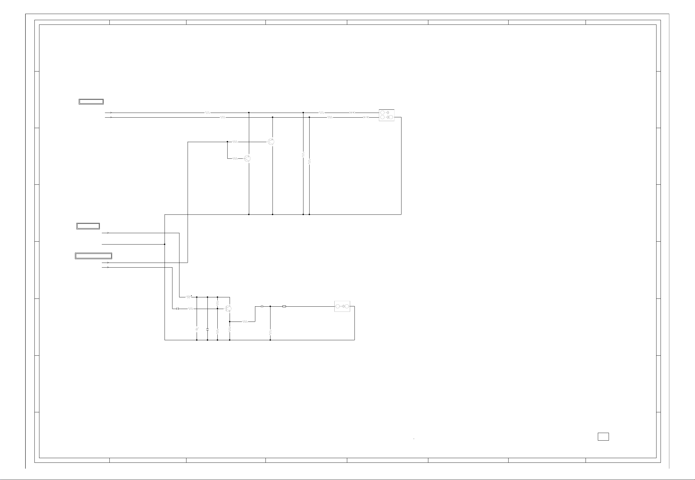
ABC D E F GH
8
AV JACK2 SCHEMATIC DIAGRAM
8
(AV PCB)
7
6
FROM/TO STEREO
AUDIO_JACK_OUT_L
AUDIO_JACK_OUT_R
R4235
R4221
39K
R4226
39K
R4237 270
R4238 270
R4236
100
100
0.3
R4232
2.2K
R4229
2.2K
0.3
0
0
MUTE
Q4207
KTC3875S_Y_RTK
0
0
MUTE
Q4209
KTC3875S_Y_RTK
W822
W837
AUDIO OUT
J4201
AV2-13P2-07H
L
R
23
H1 H2
E
1
5
7
6
5
FROM/TO POWER
P.CON+5V
GND
FROM/TO TUNER/OUT JACK
EXT_MUTE
4
3
2
SW_SPDIF
C4266
0.1 B
L4201
R4208
1.5K
4
COAXIAL JACK
J4202
AVG-2-13
H
E
1
2
3
R4206
R4207
1K
1.6
1.5K
4.9
D AUDIO DRIVER
Q4202
KTC3875S_Y_RTK
1.2
390
R4205
R4204
C4234
0.1 B
56
FCM1608CF-600T06
100K
R4203
B4202
100uH0305
10016V YK
C4237
C4236
0.022 B
2
1
H-13
NOTE:THIS SCHEMATIC DIAGRAM IS THE LATEST AT THE TIME
OF PRINTING AND SUBJECT TO CHANGE WITHOUT NOTICE
NOTE:THE DC VOLTAGE AT EACH PART WAS MEASURED
WITH THE DIGITAL TESTER WHEN THE COLOR BROADCAST
WAS RECEIVED IN GOOD CONDITION AND PICTURE IS NORMAL.
PCBD20
CMF090
1
ABC D E F GH
H-14
Page 60

ABC D E F GH
TUNER SCHEMATIC DIAGRAM
8
(AV PCB)
DIGITAL/ANALOG TUNER W/NTSC_MPX
TU5801
TUMUDTR-V110V
8
Q5805
FROM/TO SHIELD DIGITAL
W901
W899
CD3801
TM101
W900
W902
W903
W898
09119904
ETR0088-010021
SIF
IF_OUT_2
IF_OUT_1
IF_AGC
FROM/TO TUNER/OUT JACK
FROM/TO AV SWITCH2
TUNER_VIDEO
DTUNER_Y
DTUNER_PB
DTUNER_PR
AUDIO_MUTE_L
DTUNER_RESET
DTUNER_SD_H
DTUNER_RX
DTUNER_TX
DTUNER_POWER
FROM/TO STEREO
I2SSD0_OUTA
I2SWS_OUTA
I2SSCLK_OUTA
I2SSD0_IN
I2SWS_IN
I2SSCLK_IN
SIF
7
6
5
4
3
2
OOB
7
FROM/TO POWER
GND
P.CON+5V AFT
P.CON+32V DTUNER_SPDIF
UNREG+5V AFT_1
UNREG+4V AFT_2
P.CON+32V
6
FROM/TO AV OUT
CP5801
(CP2403)
TKC-W20P-U1
1
UNREG+5V
2
UNREG+5V
3
UNREG+4V
4
5
4
3
2
UNREG+4V
5
UNREG+4V
6
REG +5V
7
8
9
10
11
12
13
14
15
CVBS OUT
16
AUDIO MUTE-L
17
18
AFT_1
19
AFT_2
20
(CP2404)
CP5802
TKC-W20P-U1
DTV_RESET
1
DTV POWER
2
TX (X240)
3
RX (X240)
4
SPDIF OUT
5
6
I2SSDO_OUTA
7
I2SWS_OUTA
8
I2SSCLK_OUTA
9
I2SSDO_IN
10
I2SWS_IN
11
I2SSCLK_IN
12
TU I2C DATA
13
TU I2C CLK
14
RF_SW
15
IF AGC
16
17
18
IF OUT1
19
IF OUT2
20
GND
GND
Y OUT
U OUT
GND
GND
V OUT
GND
GND
SD-H
GND
GND
NC
NC
UNREG+5V
UNREG+4V
P.CON+5V
DTUNER_PB
DTUNER_PR
AUDIO_MUTE_L
DTUNER_SD_H
DTUNER_RESET
DTUNER_POWER
DTUNER_RX
DTUNER_TX
DTUNER_SPDIF
I2SSD0_OUTA
I2SWS_OUTA
I2SSCLK_OUTA
I2SSD0_IN
I2SWS_IN
I2SSCLK_IN
TU_I2C_DATA
TU_I2C_CLK
IF_OUT_1
IF_OUT_2
DTUNER_Y
AFT_1
AFT_2
RF_SW
IF_AGC
P.CON+5V
RF_SW
TU_I2C_CLK
TU_I2C_DATA
C5836 47P CH
C5837 47P CH
C5838 47P CH
C5839 47P CH
C5826 47P CH
C5841 47P CH
C5843 47P CH
21 22
C5824
1
10006.3V YK
C5815
0.1 B
GND
+5V
3
B5801
BLM18PG181SN1D
B5803
BLM18PG181SN1D
0.1 B
L5801
22uH
0305
C5802
+30V
4
NCNC
B5802
BLM18PG181SN1D
TU
5
C5808
0.1 B
GND
6
0
SW
IC5801 TC7W66FU
+5V
7
SW
Q5801
KRA101SRTK
5.0
5.0
0
01.87
1.86
5678
5.01
4.85
0
3.4
0
AGC
8
1.87
1234
5.01
SW
Q5802
KRC103SRTK
SDA
9
W914
C5809
W915
0.47 B
SCL
10
11
12
L5802
22uH
C5811
47P CH
C5845
C5844
W917
R5820
100K
L5804
+5V
SIF
IF SW
IF OUT
IF AGC
IF_OUT 1
13
14
15
16
17
18
R5817
2.2K
2206.3V YK
0.1 B
C5805
C5806
0.01 B
C5807
L5803
0305
100uH
W851
R5806
100K
0.1 B
C5810
11
1016V V-S
22uH
33P CH
47P CH
C5812
C5813
0.01 B
19220
00.33.33.34.930.7 01.505.004.62.01.41.90004.90
R5807
8.2K
8.2K
R5808
R5809
0.4
0
Q5803
0
IF AMP
2SC3841-T1B_T63
IF_OUT 2
0.5
4.7K
0
R5810
23 24
R5812
R5811
390K
4.7K
0.6
Q5804
IF AMP
2SC3841-T1B_T63
1K
C5814
0.0022 B
0
1.8
R5813
R5814
12K
R5815
2.5
IF AMP
2SC3841-T1B_T63
75
12K
R5816
2.7K
ACCESSORY
R6P(AR)XICI
R6P(AR)XICI
BT001
BT002
V_OUT
AGC_OUT
AFT
CAUTION: DIGITAL TRANSISTOR
1
H-15
ATTENTION
ABC D E F GH
:LES PIECES REPAREES PAR UN ETANT
DANGEREUSES AN POINT DE VUE SECURITE
N’UTILISER QUE CELLS DECRITES
DANS LA NOMENCLATURE DES PIECES
CAUTION
:SINCE THESE PARTS MARKED BY
CRITICAL FOR SAFETY,USE ONES
DESCRIBED IN PARTS LIST ONLY
ARE
NOTE:THIS SCHEMATIC DIAGRAM IS THE LATEST AT THE TIME
OF PRINTING AND SUBJECT TO CHANGE WITHOUT NOTICE
NOTE:THE DC VOLTAGE AT EACH PART WAS MEASURED
WITH THE DIGITAL TESTER WHEN THE COLOR BROADCAST
WAS RECEIVED IN GOOD CONDITION AND PICTURE IS NORMAL.
CAUTION: DIGITAL TRANSISTOR
PCBD20
CMF090
1
H-16
Page 61

ABC D E F GH
MICON SCHEMATIC DIAGRAM
8
7
6
5
4
3
2
(SCALER PCB)
FROM/TO SCALER
DVB_FAN_ON-H
DVD/AV3
DTUNER_H
STANDBY_LED
REMOCON_IN
AFT
SCART1_Y
EXT_MUTE-H
POWER_FAIL
POWER_ON-H
LCD-H
LCDON
LIGHT_CTL
STEREO_RESET
SDA1
SCL1
4SI_SCL
4SI_SDA_IN
4SI_SDA_OUT
4SI_CHIP_SE
AUDIO_MUTE
SCALER_RESET
S_DET
SW_SCART
SCART_AUDIO_SW
DVS
DVB_MUTE-L
DVB_RX
DVB_TX
DVB_RESET-L
DVB_POWER_CTL-H
AFT_1[LOW]
AFT_2[HIGH]
SD_H
FROM/TO ADC
SCL1
SDA1
DDVS
FROM/TO INTERFACE_HDMI IC
HDMI_H
FROM/TO REGULATOR
AT+3.3V
P.CON+3.3V
SCALER-H
P.CON+5V
AT+5V
HDMI_H
GND
FROM/TO AV SWITCH1
C_SYNC
SD_SW1
LEVEL SHIFT
Q104
KTK5132E
5.03.3
S
D
EEPROM_SCL
G
5.0
D
R192
5.6K
R178
4.7K
R120
NC
1K
R123
NC
1K
100
4.7K
R138
R140
RESET IC
IC102 PST3229NR
R135
10K
D105
C128
0.1 F
C131
0.01 B
3.3
5.6K
R193
EEPROM_SDA
AUDIO_MUTE
EXT_MUTE-H
STANDBY_LED
R122
4.7K
HDMI_H
JG135
R145
100
R146
JG136
R147
DVD_RX
100
W885
4.7K
00
3.4 3.4
DVD_TX
R163
1K
NCNC
OUTNCINNCGND
123
0
10K
R149
0.4750V V-S
2.250V V-S
C136
SCART_AUDIO_SW
DVB_RESET-L
DVB_POWER_CTL-H
DVB_MUTE-L
R141
100
R142
100
NC
0000000000002.51 3.2 3.4 3.2 3.23.2
51525354
DVB_SW-H
EEPROM_SCL
EEPROM_SDA
SD_SW1
P50/^WRL/^WR
HDMI/DVI
SCALER_SW
YUV_SW
COMPONENT/HDMI
HDMI_H
DVB_RX
DVB_TX
(RST1)
(CLK1)
DVD_RX
DVD_TX
NC
NC
LIGHT_CTL
JG134JG112
1B
C139
0
NC
50
0
NC
0
DVB_FAN_ON-H
0
0
NC
0
0
0
NC
3.2
0
NC
3.2
40 41 42 43 44 45 46 47 48 49
0
EPM
0
NC
0
NC
0
0
NC
0
0
0
3.2
30 31 32 33 34 35 36 37 38 39
3.2
3.2
3.2
0
26 27 28 29
DDVS
R112 1K
LIGHT_CTL
JG129
R114 100
SCL1
JG102
JG105
JG106
R119
4.7K
R197
R115 100
SDA1
4.7K
R165
4.7K
JG107
565758596606162636465666768697707172737475
AUDIO_MUTE
EXT_MUTE-H
POWER ON-H
SYNC_HD_IN
RB520S-30-TE61
POWER_ON-H
R137
4.7K
R136
4.7K
55
NC
STEREO_RESET
SDA1
28
SCL1
27
NC
26
NC
DVD POWER ON-H
NCNC
R10927K
DVD_POWER
SD_H
SCART1_Y
DVS DVB_FAN_ON-H
SCALER-H
R159 4.7K
START_SW
DVD_RESET
SCALER_RESET
R158 4.7K
S_DET SD_SW1
SW_SCART
IIC_OFF
R102 10K
LCD-H
AFT_1[LOW]
AFT_2[HIGH]
LCDON
AFT
KEY-B DVB_RX
KEY-A DVB_TX
DTUNER_H
DVD/AV3
P.CON+3.3V
R103
2.2K
R104
R200
1K
D106 UDZS5.6B
D101 UDZS5.6B
C106 0.1 B
C104 0.1 B
JG137
2.2K
R199
1K
R131 10K
C123 0.1 B
JG101
JG120
R175
JG103
JG104
2206.3V V-S
C107
C101
2206.3V V-S
C110
3.2
0
3.2
0
3.2
0
0
0
3.2
100
3.2
0
0
3.2
0
NC
0
NC
1.4
3.2 0
3.2
0
0
3.2
0.1 F
3.2
0
0
0
NC
R160
10K
JG114
2206.3V
V-S
VCC2
HP_MUTE
SCART_AUDIO_SW
50
49
48
47
POWER FAIL
REMOCON IN
NC
4.7K
C118
0.1 B
REMOCON_IN
POWER_FAIL
R153
SC2_CVBS_OUT-H
SC2_AUDIO_OUT-H
STANDBY_LED
NC
D109
C116
C117
0.1 F
NC NC
00000
76777879
5VD
SD_H
DISC_IN_DET
DVD_RESET
NC
SCALER_RESET
80818283848586878889
S_JACK_IN_DET
NC
SW_SCART/COMPONENT_SW
IIC_OFF
LCD_H
AFT_1[LOW]
AFT_2[HIGH]
LCDON
VS_ON
PDP_RLY
90919293949596979899
A_TUNER_AFT
KEY-B
KEY-A
AVSS
NC
VREF
AVCC
100
110
3.2 3.23.4 3.23.200003.23.303.093.23.23.33.163.2 003.2 003.2 0
R161
C_SYNC
C_SYNC
R154 4.7K
4.7K
4SI_CHIP_SE
100
4SI_CHIP_SE
4SI_DATA_OUT
3
4
R156 4.7K
R155 4.7K
4SI_SDA_OUT
4SI_SDA_IN
98
99
4SI_DATA_IN
NC
V_SYNC
COMPOSITE/RGB
DVB_ASPECT_IN
75 HEADPHONE_IN
76 SCALER-H
DTUNER_H
DVD/AV3
HDMI_MUTE
BYTE
CNVSS
4SI_CLK
5
R105
4.7K
R106 4.7K
R157 4.7K
4SI_SCL
CNVSS
DVB_MUTE-L
A_TUNER_AGC_IN
DVB_POWER_CTL-H
(32KHz_OUT)
(32KHz_IN)
8
9
JG116
JG118
0.1 B
C109
NCNC
2.8 2.8 NC
VSS
SCART3_SW
DVB_RESET-L
SCART1_SW/S_DET!
SCART2_SW/S_DET2
MICOM
IC101
OEC7155B
RESET
XOUT
11 12 13 14 15 16 17 18 192 20 21 22 23 24 25
14
C111
VCC1
XIN
VSS
C113
0.1 B
R107
X101
100WT01611
16MHz
C114
18P CH
18P CH
JG127
JG130
JG131
4.7K
R117
4.7K
R194
100
LEVEL SHIFT
Q106
KTK5132E
S
3.3
3.3
R195
100
R134
R181 1K
4.7K
R129
R118
R111
10K
R116
4.7K
1006.3V
C125
G
1K
4.7K
RB520S-30-TE61
V-S
C126
AT+5V
45
RST1
CLK1
DDVS
3.3
0
AT+3.3V
SCALER_RESET
4SI_CHIP_SE
4SI_SCL
4SI_SDA_IN
4SI_SDA_OUT
EEPROM_SCL
EEPROM_SDA
IIC_OFF
DVD_TX
RST1
AT+5V
CLK1
DVD_RX
CNVSS
EEPROM_SCL
EEPROM_SDA
5.0
0
4.9
0
SW
Q101
KRC103SRTK
R151
10K
W897
5.0
5678
SDA
P.CON+5V
SW
Q105
KRA103SRTK
STEREO_RESET
CHIP_SELECT
4SI_SCL
4SI_SDA_IN
4SI_SDA_OUT
EEPROM_SCL
EEPROM_SDA
5.0
SCL
PC_CONTROL
CP103
A2001WV2-7P
AT+3.3V
RESET
GND
CP101
A2001WV2-5P
GND
IIC_OFF
GND
W820
5.0 5.0 0 5.0
5678
SDA
GND
0 5.0 5.0 5.0
5.0
0
VCC
TEST
FROM/TO JACK
DVD_POWER
DVD_RX
DVD_TX
START_SW
DVD_RESET
KEY-A
KEY-B
8
7
6
7
6
5
4
3
2
1
1
2
3
4
5
SCL
FROM WRITER
MICON_DATA
CP102 A2001WV2-10P
NC
VCCA0
TEST
A1
1234
R189
10K
GND
1
TX
2
BUSY
3
4
VCC
5
CLK
6
RX
7
CNVSS
8
RESET
9
GND
10
EEP ROM IC 256K
IC103 AT24C256N-10SU-2.7
R188
10K
5
4
3
2
1
H-17
VSS
A2
A1
CAUTION: DIGITAL TRANSISTOR
CAUTION: DIGITAL TRANSISTOR
NOTE:THE DC VOLTAGE AT EACH PART WAS MEASURED
WITH THE DIGITAL TESTER WHEN THE COLOR BROADCAST
WAS RECEIVED IN GOOD CONDITION AND PICTURE IS NORMAL.
A0
0000
NOTE:THIS SCHEMATIC DIAGRAM IS THE LATEST AT THE TIME
OF PRINTING AND SUBJECT TO CHANGE WITHOUT NOTICE
1234
EEP ROM IC 256K
IC104 AT24C256N-10SU-2.7
PCBDS0
CEF170
1
ABC D E F GH
H-18
Page 62

ABC D E F GH
SCALER SCHEMATIC DIAGRAM
8
7
6
5
4
3
2
1
H-19
8
7
6
5
4
3
2
1
FROM/TO TUNER/OUT JACK
(CP4204)
CP802
00_6232_030_006_800+
1
STANDBY LED
2
REMOCON IN
3
AFT
4
5
6
AUDIO_MUTE
7
EXT_MUTE-H
8
GND
9
SCART1_B
10
GND
11
SCART1_G
12
GND
13
SCART1_R
14
GND
15
AFT_2/DTV_CVBS
16
GND
17
SCART1_Y
18
19
20
POWER_FAIL
21
POWER_ON-H
22
AFT_1
23
LCDON
24
DVB_FAN_ON-H
25
LCD-H/PDP_RLY
26
S_DET
27
28
SW_YUV1/2
29
30
LIGHT CTL/PSU_5VD
FROM/TO AV SWITCH2
(CP4203)
CP803
00_6232_029_006_800+
1
DVD/AV3_SW
2
DTUNER_H
3
DTV_MUTE_L
4
5
DTUNER_RX
6
GND
7
DTUNER_TX
8
9
DTUNER_RESET_L
10
GND
11
SW_AUDIO_R(PC)
12
GND
13
SW_AUDIO_L(PC)
14
15
STEREO_RESET
16
17
SCART_AUDIO_SW
18
SDA1
19
SCL1
20
GND
21
DTUNER_POWER
22
GND
23
DTUNER_SD_H
24
GND
25
SWITCH_CVBS
26
GND
27
SWITCH_VIDEO_Y
28
GND
29
SWITCH_VIDEO_C
FROM/TO AV SWITCH1
SW_G/SW_Y
SW_R/SW_CR
SW_B/SW_CB
SW2_R/CR
SW2_G/Y
SW2_B/CB
SW_CVBS
SW_VIDEO_Y
GND
(SCALER PCB)
STANDBY_LED
REMOCON_IN
AFT
NC
NC
NC
NC
NC
NC
NC
NC
NC
18
19
20
C801
1B
D807
D808
1SS355
1SS355
SW2_B/CB
SW2_G/Y
SW2_R/CR
GND
W824
W875
W873
SW_AUDIO_R[PC]
SW_AUDIO_L[PC]
W809W930
W801W929
AUDIO_MUTE
EXT_MUTE-H
AFT_2[HIGH]
SCART1_Y
POWER_FAIL
POWER_ON-H
AFT_1[LOW] DDHS
LCDON
DVB_FAN_ON-H
LCD-H
S_DET
SW_SCART
LIGHT_CTL
DVD/AV3 DR6
DTUNER_H
DVB_MUTE-L
DVB_RX
DVB_TX
DVB_RESET-L
STEREO_RESET
SCART_AUDIO_SW DG9
SDA1
SCL1 DG6
DVB_POWER_CTL-H
SD_H
17 16
390
R808
W883W803
GND
W802W931
C810
0.1 B
SCALER_RESET
4SI_SCL
4SI_SDA_OUT
4SI_SDA_IN
4SI_CHIP_SE
DIGITAL+3.3V
B801
BLM18PG181SN1D
C814
0.1 B
C815
2206.3V
V-S
C812
0.1 B
C816
0.1 B
C818
0.1 B
C817
0.1 B
C819
0.1 B
15
SW_CVBS
SW_VIDEO_Y
SW_VIDEO_C
P.CON+3.3V
ANALOG+3.3V
B802
BLM18PG181SN1D
DPR4
DPR5
DPR6
DPR7
DDVS
SW_CVBS
C883 0.1 B
C823 0.1 B
SW_R/SW_CR
SW_VIDEO_C
UDZS5.6B
SW_B/SW_CB
SW_VIDEO_Y
C820
0.1 B
C827
0.1 B
C2802_1
4704V V-S
C2801_1
V-S
C824 0.1 B
W805
D802
C826
0.1 B
D803
W807
R806
10K
4704V
C822
0.1 B
C836 0.1 B
C837 0.1 B
C838 0.1 B
C839 0.1 B
C840 0.1 B
C841 0.1 B
C830 0.1 B
UDZS5.6B
C842 0.1 B
C843 0.1 B
C844 0.1 B
C832 0.1
C834 0.1 B
C845 0.1 B
C846 0.1 B
C847 0.1 B
C859 0.1 B
C876 0.1 B
D805
UDZS5.6B
R807
10K
R805
10K
C835
0.1 B
2206.3V
V-S
C850
1.6
1.2
0.7
0.9
3.4
3.4
1.6
1.1
0.7
1.3
3.4
3.4
3.4
B
1.6
1.1
0.7
0.5
3.4
1.3
1.3
3.4
3.4
3.7
3.7
3.3
3.3
3.4
C7239 2.2 B
C7238 2.2 B
DPR3
DPR2
DPR1
DPR0
DPB7
DPB6
DPB5
DPB4
DPB3
DPB2
DPB1
DPB0
C851
0.1 B
1.5
3.3
0
3.4
110
DVDD33
3.4
PXD24
3.4
3
PDX25
3.4
4
PDX26
3.4
5
PDX27
3.4
6
VDIN
3.4
HDIN/FBIN
3.4
DVDD33
0
DGND
VRPD
VROD
111213141516171819 22021222324
VRMD
VIND
AVDDD2
0
AVSSD2
AVDDD1
0
AVSSD1
VRPC
VROC
VRMC
VINC
AVDDC2
0
AVSSC2
AVDCC1
0
AVSSC1
2526272829
DVDD
0
DVSS
1.6
VRPB
1.1
VROB
0.7
VRMB
30313233343536373839
0.5
VIN1B
3.4
AVDDB2
2.0
VIN2B
0
AVSSB2
3.4
AVDDB1
0
AVSSB1
VRPA
VROA
VRMA
VIN1A
NC
40414243444546474849
AVDDA2
VIN2A
0
AVSSA2
VIN3A
AVDDA1
0
AVSSA1
0
SVSS
DVDD33
0
DGND
RESET
50
QOECTL
51525354
HDIN2
VDIN2
DVDD33
55
0
C849
0.1 B
C7241 2.2 B
C7240 2.2 B
C7242 2.2 B
3.3
3.3
3.3
PXD21
PXD22
214
215
216
55
56
MPWEL
MPOE
60 61 62 63 64 65 66 67 68 69770 71 72 73 74 75 76 77 78 79880 81 82 83 84 85 86 87 88 89990 91 92 93 94 95 96 97 98 99
56 57 58 59
1.5
3.3
3.3
3.3
3.3
NR801
4D03WGJ0000T5E
3.3
3.3
PXD16
PXD17
PXD20
PXD23
DVDD15
DGND
DGND
DVDD15
57
MPWEL
MPCE
MPAH/PCXLKI
DVDDSD
3.3
3.3
R804
10K
NR808
4D03WGJ0103T5E
C853
0.1 B
3.3
3.3
3.3
3.3
PXD13
PXD14
PXD15
DVDDSD
MDQ15/C656IN7
MDQ14/C656IN6
MDQ13/C656IN5
MDQ12/C656IN4
3.3
3.3
3.3
3.3
C852 0.1 B
3.3
3.3
3.3
PXD11
PXD12
MDQ11/C656IN3
DVDD33
0
3.3
3.3
C855 0.1 B
C857
3.3
PXD10
DGND
1.5
0.1 B
3.3
PXD07
DVDD15
3.3
DPG7
DPG6
C860
0.1 B
1.5
3.3
3.3
DGND
PXD06
DVDD33
DVDD15
MDQ10/C656IN2
MDQ9/C656IN1
MDQ8/C656IN0
MDQ7/C656OUT7
3.3
3.3
3.3
3.3
R817
10K
C858 0.1 B
R818
2206.3V V-S
C856
DPG5
DPG4
DPG3
DPG2
3.3
3.3
3.3
PXD02
PXD03
PXD04
PXD05
MDQ6/C656OUT6
MDQ5/C656OUT5
MDQ4/C656OUT4
MDQ3/C656OUT3
3.3
3.3
3.3
R821
R819
10K
R822
R820
10K
10K
NR809
4D03WGJ0103T5E
DPG1
DPG0
DDCK
W810
B803
FCM1608CF-600T06
3.3
3.3
3.3
3.300
PXCLK
PXD00
PXD01
DVDDSD
SCALER
IC801
R8J66607A72FP
MDQ2/C656OUT2
MDQ1/C656OUT1
DVDDSD
DGND
0
3.3
3.3
3.3
R823
10K
10K
10K
C862 0.1 B
R825
1M
X801
54MHz
C861
7PCH
C863
0.1 B
R831
NCNCNCNCNCNCNC
00000
DGND
QBLCA
QBLCB
QBLCC
QBLCD
MPSEL0
XIN
XOUT
MPSEL1
MDQ0_C656OUT0
0
0
0
3.3
2.1
R828 10K
R826 10K
R829 10K
470
R830
W905
21
C868
7PCH
10K
0
QRR7
TSTCLK
QE/PXCLK0QHQV
3.3
3.3
R844 47
DHS
C871
QRR5
QRR6
QDRVHA/QDE
3.3
3.3
NC
R845 47
R846
DVS
DEN
0.1 B
NC
000
QRR4
DVDD33
3.3
47
3.3
DVDD33
DGND
0
C870 0.1 B
0
DGND
DVDD15
1.5
NCNCNC
C872
1.5
DVDD15
QDRVHB
0
C873
0.1 B
NCNCNC
000
QRR3
QDRVHC
0.1 B
C886
0.1 B
C878
C877
QRR1
QRR2
163
164
165
106
107
108
QDRVHD
QDRVHE
000
NC
C875
0.1 B
3.3
3.3
0.1 B
0.1 B
NCNCNCNCNC
0
3.3
00000
QRR0
DGND
DVDDSD
DVDD33
DGND
DVDD15
QBR4
QGL0
DVDD15
DGND
DVDD33
DGND
DVDDSD
QDRVHF
101102 103104105 106107108
100
0
NCNCNC
3.3
C879 0.1 B
NOTE:THE DC VOLTAGE AT EACH PART WAS MEASURED
NOTE:THIS SCHEMATIC DIAGRAM IS THE LATEST AT THE TIME
0
1.5
163164165166167168169170171172173174175176177178179180181182183184185186187188189190191192193194195196197198199200201202203204205206207208209210211212213214215216
3.3
DVDD33
0
NC
QBR3
QBR5
QBR6
QBR7
QDRVVA
QDRVVB
3.3
000
B804
R833
DCLK1
WITH THE DIGITAL TESTER WHEN THE COLOR BROADCAST
WAS RECEIVED IN GOOD CONDITION AND PICTURE IS NORMAL.
QBR2
QBR1
QBR0
DGND
DVDD33
QGR7
QGR6
QGR5
QGR4
QGR3
QGR2
DVDD33
DGND
DVDD15
QGR1
QGR0
QCLKR
QRL7
QRL6
QRL5
QRL4
QRL3
DVDD33
DGND
DVDD15
QRL2
QRL1
QRL0
QBL7
QBL5QBL6
QBL5
QBL4
QBL3
QBL2
DVDD33
DGND
DVDD15
QBL1
QBL0
QGL7
QGL6
QGL5
DGND
DVDD33
QGL4
QGL3
QGL2
QGL1
TEST1
LPF1
TEST0
QCLKL
DVD33
109110 111112113 114115116 117118119120121122123124125126127 128129130 131132133 134135136137138139140141142143144 145146147 148149150 151152153154155156157158 159160161 162
0
1.5
3.3
C884 0.1 B
FCM1608CF-600T06
47
22
0
NC
0
NC
0
NC
0
3.3
0
NC
0
NC
0
NC
0
NC
0
NC
0
NC
3.3
0
1.5
0
NC
0
NC
0
NC
3.3
3.3
3.3
3.3
3.3
3.3
0
1.5
3.3
3.3
3.3
3.3
3.3
3.3
3.3
3.3
3.3
3.3
0
1.5
3.3
3.3
4D03WGJ0470T5E
3.3
3.3
3.3
0
3.3
3.3
3.3
3.3
3.3
0
1.5
R835 10K R834
0
3.3
R836
1K
0.01 B
C888
0.001 B
NR806
OF PRINTING AND SUBJECT TO CHANGE WITHOUT NOTICE
C889
0.1 B
10K
C887
C891
0.1 B
C892
0.1 B
C898
2206.3V
V-S
C893
0.1 B
NR802
4D03WGJ0470T5E
C894
0.1 B
C813
0.1 B
NR803
4D03WGJ0470T5E
NR804
4D03WGJ0470T5E
NR805
4D03WGJ0470T5E
C895 0.1 B
C896
0.1 B
C821
0.1 B
NR807
4D03WGJ0470T5E
C897
0.1 B
GND
DR9
DR8
DR7
DR5
DR4
DR3
DR2
DB9
DB8
DB7
DB6
DB5
DB4
DB3
DB2
DG8
DG7
DG5
DG4
DG3
DG2
B805
BLM18PG181SN1D
P.CON+1.5V
FROM/TO ADC
DDHS
DDVS
DDCK REMOCON_IN
DPR7
DPR6 SCART1_Y
DPR5
DPR4
DPR3 POWER_FAIL
DPR2
DPR1
DPR0 LCD-H
DPG7 LCDON
DPG6
DPG5
DPG4 STEREO_RESET
DPG3
DPG2
DPG1
DPG0
DPB7
DPB6
DPB5
DPB4
DPB3
DPB2
DPB1
DPB0
FROM/TO LVDS
DR2 DVD/AV3
DR3
DR4
DR5
DR6
DR7 DVB_RESET-L
DR8
DR9
DG2 AFT_1[LOW]
DG3
DG4
DG5
DG6
DG7
DG8
DG9
DB2
DB3
DB4
DB5
DB6
DB7
DB8
DB9
DCLK1
DVS
DHS
DEN
FROM/TO REGULATOR
P.CON+1.5V
P.CON+3.3V
GND
FROM/TO JACK
SW_AUDIO_R[PC]
SW_AUDIO_L[PC]
PCBDS0
CEF170
FROM/TO MICON
STANDBY_LED
AFT
EXT_MUTE-H
POWER_ON-H
LIGHT_CTL
AUDIO_MUTE
SDA1
SCL1
SCALER_RESET
4SI_CHIP_SE
4SI_SDA_OUT
4SI_SDA_IN
4SI_SCL
S_DET
SW_SCART
SCART_AUDIO_SW
DVS
DVB_FAN_ON-H
DTUNER_H
DVB_MUTE-L
DVB_RX
DVB_TX
DVB_POWER_CTL-H
SD_H
AFT_2[HIGH]
ABC D E F GH
H-20
Page 63

ABC D E F GH
8
ADC SCHEMATIC DIAGRAM
8
(SCALER PCB)
FROM/TO MICON
SCL1
7
6
5
FROM/TO INTERFACE_HDMI IC
4
3
2
SDA1
DDVS
FROM/TO SCALER
DDHS
DDVS
DDCK
DPR7
DPR6
DPR5
DPR4
DPR3
DPR2
DPR1
DPR0
DPG7
DPG6
DPG5
DPG4
DPG3
DPG2
DPG1
DPG0
DPB7
DPB6
DPB5
DPB4
DPB3
DPB2
DPB1
DPB0
DDHS
DDVS
DDCK
DPR7
DPR6
DPR5
DPR4
DPR3
DPR2
DPR1
DPR0
DPG7
DPG6
DPG5
DPG4
DPG3
DPG2
DPG1
DPG0
DPB7
DPB6
DPB5
DPB4
DPB3
DPB2
DPB1
DPB0
FROM/TO REGULATOR
P.CON+3.3V
GND
DIGITAL
ANALOG
L2101
22uH
NLCV32T
4D03WGJ0101T5E
DPG7
DPG6
DPG5
DPG4
4D03WGJ0101T5E
DPG3
DPG2
DPG1
DPG0
4D03WGJ0101T5E
DPB7
DPB6
DPB5
DPB4
4D03WGJ0101T5E
DPB3
DPB2
DPB1
DPB0
L2103
47uH
NLCV32T
1006.3V V-S
C2103
NR2101
NR2102
NR2103
NR2104
L2102
22uH
NLCV32T
C2105
0.1 B
C2106
1
7
DPR0
DPR1
DPR2
DPR3
DPR4
DPR5
DPR6
DPR7
23
RED1
GND
GND
C2112
RED2
PVD
C2113
0.1 B
NR2106
4D03WGJ0101T5E
RED4
RED3
GND
PVD
R2102
0.1 B
R2116
RED6
RED5
AD CONVERTER
IC2101
MST9883C-LF-110
COAST
HSYNC
1K
10K
3.33.33.33.303.33.33.33.3 3.33.33.3
RED7
VSYNC
NR2105
C2108
0.1 B
4D03WGJ0101T5E
C2110
0.1 B
0
110111213141516171819 220
GND
3.3
GREEN7
3.3
GREEN6
3.3
GREEN5
3.3
5
GREEN4
3.3
6
GREEN3
3.3
GREEN2
3.3
GREEN1
3.3
9
GREEN0
0
GND
3.3
VDD
3.3
BLUE7
3.3
BLUE6
3.3
BLUE5
3.3
BLUE4
3.3
BLUE3
3.3
BLUE2
3.3
BLUE1
3.3
BLUE0
0
GND
0
1006.3V V-S
VDD
VDD
RED0
80
21 GND
VDD
VDD
C2111
0.1 B
GND
0.1 B
21 22 23 24 25 26 27 28 29330 31 32 33 34 35 36 37 38 39440
3.3 3.3 0 0 3.3 3.3 0 3.3 3.8 3.8 0 1.3 1.3 3.3 0 0.4 0 3.3 0
C2109
VDD
GND
C2116
R2117
0.0039 B
10K
GND
FILT
R2104
R2103
C2120
DDCK
B2101
DATACK
PVD
8.2K
0.039 B
DDHS
FCM1608CF-600T06
W886
100
NC
HSOUT
SOGOUT
61VDGND
41 GND
PVD
GND
C2124
2206.3V V-S
C2121
DDVS
VSOUT
MIDSCV
W888
0.1 B
GND
CLAMP
R2108
C2125
0.1 B
03.303.103.13.00
VD
REF BYPASS
RAIN
SOGIN
GAIN
BAIN
VD
1K
C2126
0.1 B
616263646566676869770717273747576777879880
GND
SDA
SCL
GND
GND
GND
GND
6
0
60
C2130
3.3
0.1 B
1.3
3.9
3.9
0
A0
0.5
0
C2133
3.3
VD
3.3
VD
0
50 51 52 53 54 55 56 57 58 59
0.9
0.5
0
3.3
VD
3.3
VD
0
0.5
3.3
VD
0
41 42 43 44 45 46 47 48 49
GND
2206.3V V-S
C2127
2206.3V V-S
C2131
0.1 B
C2132
0.1 B
C2129
0.1 B
C2137
0.1 B
C2136
0.1 B
C2138
0.1 B
C2139
0.047 B
C2142
100P CH
C2143
0.047 B
C2140
12P CH
R2109
C2144
0.047 B
C2145
0.001 B
470
L2106
2.2uH
C2146
15PCH
KTA1504S_Y_RTK
R2111
470
R2110
BUFFER
Q2101
100
R2112
5.0
0
C2148
C2149
1K
5
100P CH
4
NLCV32T
L2107
22uH
0.1B
C2150
2206.3V V-S
R2114
0.7
100
C2151
100P CH
27
28
29
FROM/TO AV SWITCH1
SW_PR/R
SW_Y/G
SW_PB/B
3
2
1
H-21
P.CON+5V
NOTE:THE DC VOLTAGE AT EACH PART WAS MEASURED
WITH THE DIGITAL TESTER WHEN THE COLOR BROADCAST
WAS RECEIVED IN GOOD CONDITION AND PICTURE IS NORMAL.
NOTE:THIS SCHEMATIC DIAGRAM IS THE LATEST AT THE TIME
OF PRINTING AND SUBJECT TO CHANGE WITHOUT NOTICE
PCBDS0
CEF170
1
ABC D E F GH
H-22
Page 64

ABC D E F GH
8
(SCALER PCB)
LVDS
IC7201
GND
TxIN8
TxIN9
TxIN10
Vcc
TxIN11
TxIN12
TxIN13
GND
TxIN14
TxIN15
TxIN16
R-FB
TxIN17
TxIN18
TxIN19
GND
TxIN20
TxIN21
TxIN22
TxIN23
Vcc
TxIN25
ICSV385AGLFT
R7201
180
TxIN4
TxIN3
TxIN2
GND
TxIN1
TxIN0
TxIN27
LVDSGND
TxOUT0TxOUT0+
TxOUT1TxOUT1+
LVDSVcc
LVDSGND
TxOUT2-
TxOUT2+
TxCLKOUTTxCLKOUT+
TxOUT3-
TxOUT3+
LVDSGND
PLLGND
PLLVcc
PLLGND
PWRDWN
TxCLKIN
TxIN26TxIN24
GND
50 51 52 53 54 55 56
40 41 42 43 44 45 46 47 48 49
30 31 32 33 34 35 36 37 38 39
29
C7210
3.3
3.3
3.3
0
3.3
3.3
3.3
0
1.3
1.2
1.3
1.2
3.2
0
1.2
1.3
1.2
1.3
1.3
1.2
0
0
3.3
0
3.3
2.8
3.3
0
4D03WGJ0470T5E
24
4D03WGJ0470T5E
0.1 B
R7202
47
R7203
47
NR7201
NR7202
C7212
0.1 B
W811
C7217
0.1 B
C7213
C7215
150V V-S
0.1 B
B7201
FCM1608CF-600T06
LCD_TXOUT0LCD_TXOUT1-
LCD_TXOUT1+
LCD_TXOUT2-
LCD_TXCLKOUTLCD_TXCLKOUT+
C7220
0.1 B
DCLK1
3304V V-S
C7219
DR6
DR3
LCD+B
LCD_TXOUT0LCD_TXOUT0+
LCD_TXOUT1LCD_TXOUT1+
LCD_TXOUT2LCD_TXOUT2+
LCD_TXCLKOUTLCD_TXCLKOUT+
LCD_TXOUT3LCD_TXOUT3+
C7224
22016V V-S
C7228
W832
W855
W834
1B
NC
NC
NC
FROM/TO PANEL
FI-X30S-HF-NPB
GND
VDD+5V/12V
VDD+5V/12V
VDD+5V/12V
VDD+5V/12V
GND
GND
GND
GND
VDD+3.3V/NC/GND
NC/GND
GND
RXIN0RXIN0+
GND
RXIN1RXIN1+
GND
RXIN2RXIN2+
GND
RXCLK INRXCLK IN+
GND
RXIN3RXIN3+
GND
VDD+3.3V/NC/GND
VDD+3.3V/NC/GND
NC/GND
VDD+3.3V/GND
GND
CP7203
1
2
3
4
5
6
7
8
9
10
11
12
13
14
15
16
17
18
19
20
21
CD7204
22
CHRU3002
23
24
25
26
27
28
29
30
31
32
LCD PANEL
V2301
LK260T3LF12
C7204
0.1 B
7
FROM/TO SCALER
DR2
DR3
DR4
DR5
DR6
DR7
DR8
DR9
DG2
DCLK1
DG3
DG4
DG5
DG6
DG7
DG8
DG9
DB2
DB3
DB4
DB5
DB6
DB7
DB8
DB9
DVS
DHS
DEN
C7205
6
5
4
3
C7202
0.1 B
L7201
47uH
NLC3225
L7202
47uH
NLC3225
0.1 B
C7203
L7203
47uH
2206.3V V-S
NLC3225
FROM/TO REGULATAR
C7201
P.CON+3.3V
LCD+B
2
GND
W829
C7206
0.1 B
2206.3V
V-S
C7207
0.1 B
2206.3V V-S
C7208
3.3
110111213141516171819 2202122232425262728
RS
3.3
DR9 DR5
DR7 DR4
DG2
DG3 DR2
DG4 DR8
DG8
DG9 LCD_TXOUT0+
DG5
DG6
DG7
DB2
DB8 LCD_TXOUT2+
DB9
DB3 LCD_TXOUT3-
DB4 LCD_TXOUT3+
DB5
DB6
DB7
DHS DEN
DVS
C7209
TxIN5
3.3
3
TxIN6
3.3
4
TxIN7
0
5
3.3
6789
3.3
3.3
3.3
3.3
3.3
3.3
0
3.3
3.3
3.3
0
3.3
3.3
3.3
0
3.3
3.3
3.3
0
NC
3.3
3.3
3.3
2206.3V V-S
8
7
6
5
4
3
2
LVDS SCHEMATIC DIAGRAM
1
H-23
CAUTION
:SINCE THESE PARTS MARKED BY
CRITICAL FOR SAFETY,USE ONES
DESCRIBED IN PARTS LIST ONLY
ARE
CAUTION
:SINCE THESE PARTS MARKED BY
CRITICAL FOR SAFETY,USE ONES
DESCRIBED IN PARTS LIST ONLY
ARE
NOTE:THE DC VOLTAGE AT EACH PART WAS MEASURED
WITH THE DIGITAL TESTER WHEN THE COLOR BROADCAST
WAS RECEIVED IN GOOD CONDITION AND PICTURE IS NORMAL.
NOTE:THIS SCHEMATIC DIAGRAM IS THE LATEST AT THE TIME
OF PRINTING AND SUBJECT TO CHANGE WITHOUT NOTICE
PCBDS0
CEF170
1
ABC D E F GH
H-24
Page 65

ABC D E F GH
8
7
6
5
4
3
SH4301
TP003070-21
SH4302
TP003070-21
SH4303
TP003070-21
H2NC H1
1
234
E
J4301
MSD-242VA1-03_NI_FE_LF
L
MMZ1608R102CT
R
MMZ1608R102CT
B4307
B4308
C4362
1K
R4313
1K
0.001 B
R4314
C4366
C4315
C4314
1B
0.001 B
1B
R4319
R4320
180K
8.5
3.0
220K
BUFFER
Q4302
KTC3875S_Y_RTK
5.4
4.7K
R4324
R4328
3.0 2.4
R4329
180K
220K
8.5
R4333
BUFFER
Q4305
KTC3875S_Y_RTK
4.7K
C4324
22uH
10016V V-S
25
26
NLV32T
L4306
P.CON+9V
PC/DVI_A_IN_L
PC/DVI_A_IN_R
JACK SCHEMATIC DIAGRAM
(SCALER PCB)
PC/DVI_A_IN_L SW_AUDIO_L[PC]
PC/DVI_A_IN_R SW_AUDIO_R[PC]
W844W891
W845W892
C4378
470PCH
C4372
470PCH
KEY-B
KEY-A
D4301
UDZS5.6B
D4302
UDZS5.6B
DVD_POWER
DVD_RESET
START_SW
DVD_TX
DVD_RX
FROM/TO OPARATION/REMOCON
FILTER/AC INLET
CP2200
A2001WV2-3P
P.CON+9V
GND
FROM/TO AUDIO/VIDEO
CP4303
A2001WV2-6P
DVD POWER
DVD_RESET
D4310
1SS355
START_SW
TX/SSCCLK
RX/RDY(I/O(0))
FROM/TO SCALER
SW_AUDIO_L[PC]
SW_AUDIO_R[PC]
FROM/TO MICON
DVD_RESET
START_SW
DVD_TX
DVD_RX
DVD_POWER
KEY-A
KEY-B
(CP2203)
1
GND
2
KEY B
3
KEY A
FROM/TO REGULATOR
(CD702)
6
5
4
3
2
GND
1
8
7
6
5
4
3
2
1
H-25
2
PCBDS0
CEF170
NOTE:THIS SCHEMATIC DIAGRAM IS THE LATEST AT THE TIME
OF PRINTING AND SUBJECT TO CHANGE WITHOUT NOTICE
NOTE:THE DC VOLTAGE AT EACH PART WAS MEASURED
WITH THE DIGITAL TESTER WHEN THE COLOR BROADCAST
WAS RECEIVED IN GOOD CONDITION AND PICTURE IS NORMAL.
1
ABC D E F GH
H-26
Page 66

ABC D E F GH
8
AV SWITCH1 SCHEMATIC DIAGRAM
8
(SCALER PCB)
R8102
150
R8101
R8103
150
150
0.7
1K
5.0
BUFFER
Q8106
KTA1504S_Y_RTK
0
R8146
C8149
SW_Y/G
SW_PB/B
SW_PR/R
NLCV32T
L8105
22uH
0.1 B
C8150
2206.3V V-S
C8151
100P CH
P.CON+5V
7
R8145
1K
R8143
R8148
100
5.0
BUFFER
Q8105
KTA1504S_Y_RTK
0.7
100
0
6
5
SW_G/SW_Y
7
SW_B/SW_CB
SW_R/SW_CR
6
SW2_G/Y
SW2_R/CR
FROM/TO MICON
C_SYNC
5
SD_SW1
W843 W821
SW2_B/CB
R8105
150
R8104
150
W861
W862
FROM/TO SCALER
SW_R/SW_CR
SW_G/SW_Y
SW_B/SW_CB
SW2_R/CR
SW2_G/Y
SW2_B/CB
SW_CVBS
4
3
2
SW_VIDEO_Y
FROM/TO ADC
SW_Y/G
SW_PB/B
SW_PR/R
FROM/TO REGURATER
P.CON+9V
P.CON+5V
GND
C8109
C8112
1B
C8110
1B
C8113
1B
1B
SCART2 OUT CVBS SW
IC8103 MM1501XNRE
456
H
5.1
0
L
5.1
8.9
VCC
4.4
BUFFER
0
123
C8129
C8128
1B
R8113
100K
4
P.CON+5V
1K
R8131
1.0
R8130
SYSNC_SEPA
KTC3875S_Y_RTK
12K
C8147
R8128
R8129
3.3K
0.3
820P CH
Q8102
0.7
4.7K
3.1
0
0
10016V V-S
0.1 B
C8131
47uH
R8116
1K
L8102
NLCV32T
SYSNC_SEPA
KTA1504S_Y_RTK
330P CH
C8137
R8119
Q8101
820K
5.1
5.5
1.5
R8123
R8125
12K
2.7K
C8144
C8146
1B
0.1 B
C_SYNC
SYSNC_SEPA
Q8103
KTC3875S_Y_RTK
3
2
1
H-27
SW_CVBS
SW_VIDEO_Y
NOTE:THIS SCHEMATIC DIAGRAM IS THE LATEST AT THE TIME
OF PRINTING AND SUBJECT TO CHANGE WITHOUT NOTICE
SD_SW1
P.CON+9V
NOTE:THE DC VOLTAGE AT EACH PART WAS MEASURED
WITH THE DIGITAL TESTER WHEN THE COLOR BROADCAST
WAS RECEIVED IN GOOD CONDITION AND PICTURE IS NORMAL.
PCBDS0
CEF170
1
ABC D E F GH
H-28
Page 67

ABC D E F GH
8
REGULATOR SCHEMATIC DIAGRAM
8
(SCALER PCB)
FROM/TO POWER
(CP3807)
CP3201
7
6
A2001WV2-11P
1
P.CON+12V
2
P.CON+9V
3
P.CON+5V
4
AT+3.3V
5
P.CON+3.8V
6
P.CON+3.8V
7
GND
8
GND
9
GND
10
P.CON+5V
11
AT+5V
NC
B3201
BLM18PG181SN1D
B3202
BLM18PG181SN1D
B3203
BLM18PG181SN1D
BLM18PG181SN1D
B3207
BLM18PG181SN1D
BLM18PG181SN1D
B3208
BLM18PG181SN1D
B3206
B3209
5
4
C3201
22016V V-S
C3202
C3209
C3205
C3203
470P CH
470P CH
C3206
C3204
470PCH
470P CH
C3207
470PCH
470PCH
470PCH
3.3V_REG
IC3201 BA00BC0WFP
10K
R3209
V_C V_IN GND V_OUT V_ADJ
12 456
2.7 4.1 0 3.3
C32121FC3211
W860
1F
C3213
DS
1.2
R3211
6.8K
+-1%
3.9K
+-1%
R3212
1006.3V V-S
220
R3238
LCD+B
P.CON+9V
P.CON+5V
AT+3.3V
GND
AT+5V
P.CON+3.3V
HDMI_VNREG+5V
SCALER-H
R3220
D3209
EC11FS2-TE12L
10K
D3207
EC31QS04
1.5V_REG
IC3202 BD7820FP
V_C V_IN GND V_OUT V_ADJ
12 456
2.7 2.8 0 1.6 0.7
D3206
EC31QS04
1F
C3216
C3215
1F
C3223
0.1 F
C3217
DS
R3221
+-1%
1K
820
R3222
+-1%
1006.3V V-S
68
R3237
P.CON+1.5V
FROM/TO ADC
P.CON+3.3V
P.CON+5V
GND
FROM/TO SCALER
P.CON+3.3V
P.CON+1.5V
GND
FROM/TO MICOM
SCALER-H
P.CON+3.3V
AT+3.3V
AT+5V
P.CON+5V
HDMI_H
GND
FROM/TO LVDS
P.CON+3.3V
LCD+B
GND
FROM/TO JACK
P.CON+9V
GND
FROM/TO INTERFACE_HDMI IC
HDMI+5V
HDMI_VNREG+5V
GND
7
6
5
4
3
2
1
H-29
CAUTION
FROM/TO HDMI MICON2
HDMI+5V
RXT_RST#
GND
3
2
R3223
22K
KRC102SRTK
5.0 5.0
4.3
R3224
SW
Q3206
SW
Q3205
KTA1664-Y-RTF/P
1K
0
1.8
0
C3218
FROM/TO AV SWITCH1
HDMI+5V
AT+3.3V
R3242
R3235
0.6
10K
0
SW
Q3209
KTC3875S_Y_RTK
0
W867
W837
R3228
8.2K
C3219
2.2 B
2.2 B
HDMI_H
R3234
10K
3.3
0
0
10K
SW
Q3210
KTC3875S_Y_RTK
RXT_RST#
P.CON+9V
P.CON+5V
GND
CAUTION: DIGITAL TRANSISTOR
:SINCE THESE PARTS MARKED BY
CRITICAL FOR SAFETY,USE ONES
DESCRIBED IN PARTS LIST ONLY
ARE
ATTENTION
:LES PIECES REPAREES PAR UN ETANT
DANGEREUSES AN POINT DE VUE SECURITE
N’UTILISER QUE CELLS DECRITES
DANS LA NOMENCLATURE DES PIECES
NOTE:THE DC VOLTAGE AT EACH PART WAS MEASURED
WITH THE DIGITAL TESTER WHEN THE COLOR BROADCAST
WAS RECEIVED IN GOOD CONDITION AND PICTURE IS NORMAL.
NOTE:THIS SCHEMATIC DIAGRAM IS THE LATEST AT THE TIME
OF PRINTING AND SUBJECT TO CHANGE WITHOUT NOTICE
PCBDS0
CEF170
1
ABC D E F GH
H-30
Page 68

ABC D E F GH
8
7
6
5
4
3
2.8 4.5 0 1.9 0.7
C3600
D3600
EC31QS04
2
D3606
EC31QS04
2.8 5.0
C3645
1
HDMI CONNECTOR
CP3601 DC1R019JDA
19
18
17
16
15
14
13
12
11
10
9
8
7
6
5
4
3
2
1
1.8V_REG
IC3600 BD7820FP
12 456
0.1 F
C3650
0.1 F
1006.3V V-S
C3648
12 456
0.1 F
C3649
C3653
3.3V_REG
IC3602 BA00BC0WFP
0
C3651
0.1 F
1006.3V V-S
C3652
EEP_ROM IC
IC3601 BR24L02F-WE2
1234
A0
A1
A2 SCL
GND SDA
C3602
0.1 B
R3603
2.2K
D3602
C3601
0.1 B
NC
NC NC
V_ADJV_OUTGNDV_INV_C
R3623
220
R3626
2.2K +-1%
1006.3V V-S
R3627
68 +-1%
R3629
V_ADJV_OUTGNDV_INV_C
3.9K +-1%
R3624
2206.3V V-S
220
R3625
VCC
WP
D3601
C3658
220
04.9
0
0
UDZS5.6B
DET
POWER
GND
SDA
SCL
NC
CEC
CLKCLK-S
CLK+
D0D0-S
D0+
D1D1-S
D1+
D2D2-S
D2+
DS
R3600
3.3K
+-1%
0.1 F
C3655
DS
3.3 1.4
R3622
6.8K
+-1%
C3654
0.1 F
R3606
4.7K
0
5.0
5678
5.00
R3604
47K
R3605
47K
D3603
RB160L-40
RB160L-40
1K
R3602
HDMI Port Protection
4.6
IC3605 CM2021-00TR
0.1 B
CLK- CLK-
CLK+ CLK+
HOTPLUG_DET_OUT HOTPLUG_DET_IN
202122
5
5
DDC_CLK_OUT DDC_CLK_IN
0
CE_REMOTE_IN
23242526272829
3.6
TMDS_CK-
0
TMDS_GND
3.6
TMDS_CK+
3.6
D0- D0-
TMDS_D0-
0
TMDS_GND
3.6
D0+ D0+
TMDS_D0+
3.6
D1- D1-
TMDS_D1-
303132333435363738
0
TMDS_GND
3.6
D1+ D1+
TMDS_D1+
3.6
D2- D2-
TMDS_D2-
0
TMDS_GN
3.6
D2+ D2+
TMDS_D2+
0
GND
C3657
4.6
ESD_BYP
0.1 B
0
NC
+1.8V
VDD3
DDC_DAT_INDDC_DAT_OUT
CE_REMOTE_IN
TMDS_CKTMDS_GND
TMDS_CK+
TMDS_D0TMDS_GND
TMDS_D0+
TMDS_D1TMDS_GND
TMDS_D1+
TMDS_D2TMDS_GND
TMDS_D2+
GND
LV_SUPPLY
5V_SUPPLYNC
B3601
FCM1608KF-151T06
B3602
FCM1608KF-151T06
B3603
FCM1608KF-151T06
B3604
FCM1608KF-151T06
B3605
FCM1608KF-151T06
INTERFACE_HDMI IC SCHEMATIC DIAGRAM
(SCALER PCB)
0.1 B
W901
SW
47K
R3609
47K
R3601
HDMI+5V
HPD_RST
3.3
3.3
3.3
0
NC
3.6
0
3.6
3.6
0
3.6
3.6
0
3.6
3.6
0
3.6
456789
0
3
3.3
5.0
HDMI+5V
1 10111213141516 17 18 192
HDMI_VNREG+5V
HDMI_H DPR2
C36031BC3604
B3614
FCM1608KF-151T06
B3615
FCM1608KF-151T06
NOTE:THIS SCHEMATIC DIAGRAM IS THE LATEST AT THE TIME
C36051BC3607
0.001 B
OF PRINTING AND SUBJECT TO CHANGE WITHOUT NOTICE
R3607 4.7K
47K
R3608
I2C_DATC
I2C_CLKC
DSDA
DSCL DDCK
W822
C3613
0.001 B
C3609
C3610
C3606
0.1 B
1B
C3611
C3608
0.01 B
C3612
0.1 B
PWR5V
C3614
0.1 B
C3615
0.1 B
C3616
0.1 B
0.1 B
C3617
0.1 B
10 C
C3618
0.01 B
0
NC
0
NC
0
NC
1.8
0
0
3.3
3.3
3.3
3.3
0
NC
5
1.8
0
3.3
0
NC
3.3
3.4
3.4
0
3.3
3.4
3.4
0
3.3
3.4
3.4
0
3.3
3.4
3.4
0
10 C
10 C
C3619
C3621
0
3.3
1.8
0.1 B
0
IOVCC
DVCC18
0
IOGND
MUTE
0
QO5
QO4
IOVCC
IOGND
0
3.3
3.3
0.1 B
C3622
0
QO3
33343536373839
QO0
CVCC18
CGND
CI2CA
CSDA
CSCL
40414243444546474849
DSDA
DSDL
NC
PWR5V
CVCC18
PGND
PVCC
RSVD
AVCC
RXC-
50
RXC+
515253545556575859
AGND
AVCC
RX0RX0+
AGND
AVCC
RX1RX1+
AGND
6061626364
AVCC
RX2-
DGND
65 66 67 68 69770 71 72 73 74 75 76 77 78 79
0
C3620
0.1 B
C3623
0
0
0
0
QO7
QO6
SPDIF
SD3
NC
NC NCNC
3.3
4D03WGJ0330T5E
NOTE:THE DC VOLTAGE AT EACH PART WAS MEASURED
0
1.8
0
QO9
QO8
SD0
WS
3.3
3.3
I2SDATA_IND
I2SCLK_IND
I2SWS_IND
QO10
SCK
3.3
CGND
CVCC18
QO2
33
QO1
34
RX2+
63
64
AGND
SD2
SD1
0
0
NR3601
NC
WITH THE DIGITAL TESTER WHEN THE COLOR BROADCAST
WAS RECEIVED IN GOOD CONDITION AND PICTURE IS NORMAL.
0.1 B
C3625
0
3.3
IOGND
IOVCC
HDMI RECEIVER
SiI9011CLU
IOGND
MCLK
0
QO12
IC3603
CGND
0
QO11
IOVCC
80 81 82 83 84 85 86 87 88 89
3.303.301.8
33
R3630
NC
0.1 B
C3626
C3624
0.1 B
0
QO13
CVCC18
C3627
C3629
0
0
QO15
QO14
AUDPVCC18
AUDPGND
1.802.4
0.1 B
0
CGND
XTALOUT
R3612
R3670
1M
C3628 18P CH
0.1 B
1K
1.8
CVCC18
XTALIN
2.4
C3630 18P CH
0
111213141516171819 220212223242526272829 3303132
QO16
XTALVCC
3.3
X3602
0
QO17
REGVCC
3.3
R3678
28.322MHz
0
9
QO18
128
127
RSVDL
0
98
97
4.7K
R3679
0.1 B
C3631
NC NC NC NCNC NC NC NCNC NC NC NCNC NC NC NCNC NC NCNCNC
0
0
8
QO19
HSYNC
DE
IOVCC
IOGND
RESET#
0
RXT_RST#
0
0
3.3
IOVCC
SCDT
6
IOGND
INT
5
QO20
QE23
4
QO21
QE22
90 91 92 93 94 95 96
NC
3.3
3.3
3.3
3.3
100
H_INT
DPR7
DPR6
DPR5
0
QO22
QE21
3.3
DPR4
3.3
0
110
QO23
VSYNC
CGND
CVCC18
QE0
QE1
QE2
QE3
IOVCC
ODCLK
IOGND
QE4
QE5
QE6
QE7
CGND
CVCC18
QE8
QE9
QE10
QE11
IOVCC
IOGND
QE12
QE13
QE14
QE15
QE16
QE17
QE18
QE20
QE19
3.3
3.3
NR3602
4D03WGJ0000T5E
3.3
3.3
NC
C3635
0
0.1 B
1.8
3.3
3.3
3.3
3.3
3.3
3.3
C3633
0
0.1 B
3.3
3.3
3.3
3.3
C3636
0
0.1 B
1.8
3.3
3.3
3.3
3.3
3.3
C3632
0
0.1 B
3.3
3.3
3.3
3.3
3.3
101 102 103 104 105 106 107 108 109 110 111 112 113 114 115 116 117 118 119 120 121 122 123 124 125 126 127 128
3.3
100
3.3
3.3
C3634
0
97 98 99
0.1 B
R3620
33
R3621
33
NR3604
4D03WGJ0000T5E
R3617
B3610
120
FCM1608CF-600T06
NR3605
4D03WGJ0000T5E
NR3606
4D03WGJ0000T5E
NR3607
4D03WGJ0000T5E
NR3608
4D03WGJ0000T5E
8
FROM/TO ADC
DDVS
DDHS
DDCK
DPB0
DPB1
DDVS
DDHS
30
DPB0
DPB1
DPB2
DPB3
DPB4
DPB5
DPB6
DPB7
31
DPG0
DPG1
DPG2
DPG3
DPG4
DPG5
DPG6
DPG7
32
DPR0
DPR1
DPR3
DPB2
DPB3
DPB4
DPB5
DPB6
DPB7
DPG0
DPG1
DPG2
DPG3
DPG4
DPG5
DPG6
DPG7
DPR0
DPR1
DPR2
DPR3
DPR4
DPR5
DPR6
DPR7
FROM/TO MICON
HDMI_H
FROM/TO HDMI MICON2
RXT_RST#
H_INT
I2C_CLKC
I2C_DATC
HPD_RST
I2SCLK_IND
I2SWS_IND
I2SDATA_IND
SW
VDD3
DDVS
FROM/TO REGULATOR
HDMI+5V
HDMI_VNREG+5V
GND
7
6
5
4
3
2
PCBDS0
CEF170
1
ABC D E F GH
H-32H-31
Page 69

ABC D E F GH
8
7
6
FROM/TO INTERFACE_HDMI IC
5
VDD3
I2C_CLKC
I2C_DATC
H_INT
DDVS
RXT_RST#
HPD_RST
I2SWS_IND
I2SDATA_IND
I2SCLK_IND
HDMI MICON2 SCHEMATIC DIAGRAM
8
(SCALER PCB)
SW
W957
HDMI+5V
4.7K
EEPROM
R3640
IC3608 BR24L32F-WE2
0
1234
A0
0
A1
5.0
A2
0
SW
R3637 4.7K
R3639 4.7K
VCC
SCL
SDAGND
WP
C3637
5.0
0
4.6
4.6
5678
0.1 F
3.3
G
3.0
4.6
D
BUFFER
Q3605
S
KTK5132E
C3638
R3641
0.1 F
3.3 4.6
2.2K
0.1 F
0.1 F
C3639
C3640
R3644 4.7K
R3643 4.7K
UC_SCL
UC_SDA
D
G
BUFFER
Q3606
S
KTK5132E
3.0
C3641
R3645 8.2K
1016V V-S
C3642
18P CH
C3643
18P CH
D3613
UDZS3.3B
X3601
11.0592MHz
100CT01101
R3619 4.7K
JG3605
R3631 4.7K
R3628 4.7K
D3609
UDZS3.3B
NCNC
2.7
NC
1213141516171819
5.0
NC
2.7
2.4
0
1.2
NC
0
NC
5.0
NC
5.0
5.0
NC
1.3
NC
CEC
P3.3/INT1-
RX2_INT
12
X2
13
X1
GND
NC
MUTE_CTL
NC
21
VIDEO_SEL
22
AUDIO_SEL
202122
23 24 25 26 27 28 29330 31 32 33
5.0 5.0 5.0 5.0 1.5 1.4 5.0 0 3.4 0 5.0
HPD_RST
NC
NC
NC NC NC NC NC NCNC
NC
4.91.245.0 05.03.04.9
NC
TXD
RX1_INT
AKM_SMUTE
HDMI MICON
IC3611
SST89E58RD2-40-C-TQJE(HD101)
NC
ALE/PROG-
PSEN-
C3646
0.1 F
4
56789
RXD
NC 44
NC
AKM_ACKS
RX2_RST
EA-/VPP
RESET
NC
W970
43
35
34
4.6 04.62.5
CSDA
NC
W969
2
CSCL
H_SYNC
V_SYNC
PROGRAM
AKM_PD
RX1_RST
P_SEL
NC
11011
NC
NC
VCC
AKM_DIF0
5.0
5.0
5.0
0
5.0
40 41 42 43 44
0
5.0
5.0
3.3
5.0
0
34 35 36 37 38 39
W949
NC
NC
NC
R3648 33
R3647 10K
NC
R3632 4.7K
R3654 4.7K
R3649 4.7K
C3647
R3652 4.7K
0.1 F
R3653 4.7K
R3633
5.6K
LEVEL SHIFT
Q3600
KTK5132E
D
G
3.3
R3634
00
S
100
C3656
100P CH
TX
RX
H_INT
DDVS
RXT_RST#
NC
NC NC
CP3604
A2001WV2-9P
VCC
RX
TX
EN
GND
NC
UC_SCL
UC_SDA
1
2
3
4
5
6
7
8
9
7
6
5
4
FROM/TO STEREO
CP3602
3
2
1
(CP901)
A2001WV2-4P
4
HDMI_I2SSCK/MCKL
3
HDMI_I2SSDO
2
HDMI_I2SWS
1
GND
FROM/TO REGULATOR
RXT_RST#
HDMI+5V
GND
B3606
FCM1608KF-102T02
B3612
FCM1608KF-102T02
W839
W868
NOTE:THIS SCHEMATIC DIAGRAM IS THE LATEST AT THE TIME
OF PRINTING AND SUBJECT TO CHANGE WITHOUT NOTICE
HPD_RST
NOTE:THE DC VOLTAGE AT EACH PART WAS MEASURED
WITH THE DIGITAL TESTER WHEN THE COLOR BROADCAST
WAS RECEIVED IN GOOD CONDITION AND PICTURE IS NORMAL.
PCBDS0
CEF170
4
3
2
1
H-33
ABC D E F GH
H-34
Page 70

ABC D E F GH
H-35
ASIC SCHEMATIC DIAGRAM
8
HS2401
763WAA0351
ATSC/CLEAR CABLE ASIC
IC2401 X240H
(1/14 VDD) (2/14 VSS) (3/14 VSS)
ATSC/CLEAR CABLE ASIC
IC2401 X240H
(DIGITAL PCB)
ATSC/CLEAR CABLE ASIC
IC2401 X240H
ATSC/CLEAR CABLE ASIC
IC2401 X240H
(4/14 OSC)
8
C2500 0.1 B
C2505 0.1 B
C2581 0.1 B
C2582 0.1 B
7
6
5
4
FROM FLASH
3
2
DTV_RESET
FROM AV OUT
DTV_RESET
FROM POWER2
CORE_1.2V
+1.8V
+3.3V
D_GND
C2401 1 B
C2402 0.1 B
C2403 0.1 B
C2404 0.1 B
C2405 0.1 B
C2406 0.1 B
C2407 0.1 B
C2408 1 B
C2409 0.1 B
C2410 0.1 B
C2583 0.1 B
C2584 0.1 B
C2585 0.1 B
C2586 0.1 B
C2411 1 B
C2412 0.1 B
C2413 0.1 B
C2414 0.1 B
C2415 0.1 B
C2416 1 B
C2417 0.1 B
C2418 0.1 B
C2419 0.1 B
C2420 1 B
C2587 0.1 B
C2588 0.1 B
C2589 0.1 B
C2590 0.1 B
C2421 0.1 B
C2422 0.1 B
1.2
E11
VDDC
1.2
E12
VDDC
1.2
VDDC
E16
1.2
VDDC
E17
1.2
VDDC
E20
1.2
VDDC
E21
1.2
VDDC
E24
1.2
VDDC
E25
1.2
VDDC
F5
1.2
VDDC
G5
1.2
VDDC
G26
1.2
VDDC
H26
1.2
VDDC
L26
1.2
VDDC
M5
1.2
VDDC
M26
1.2
VDDC
N5
1.2
VDDC
U5
1.2
VDDC
V5
1.2
VDDC
V26
1.2
VDDC
W26
1.2
VDDC
AA5
1.2
VDDC
AB5
1.2
VDDC
AD26
1.2
VDDC
AE5
1.2
VDDC
AE26
1.2
VDDC
AF5
1.2
VDDC
AF8
1.2
VDDC
AF9
1.2
VDDC
AF12
1.2
VDDC
AF13
1.2
VDDC
AF17
1.2
VDDC
AF18
1.2
VDDC
AF21
1.2
VDDC
AF22
VDDP
VDDP
VDDP
VDDP
VDDP
VDDP
VDDP
VDDP
VDDP
VDDR3
VDDR3
VDDR3
VDDR3
VDDR3
VDDR3
VDDR3
VDDR3
VDDR3
VDDR3
VDDR3
VDDR3
VDDR3
VDDR3
VDDR3
VDDR3
VDDR3
VDDR3
VDDR3
VDDR3
VDDR3
VDDR3
VDDR3
VDDR3
VDDC18_RIGHT
VDDC18_TOP
VDDC18_BOTTOM
VDDC18_LEFT
E6
E7
E8
E9
E10
H5
K5
L5
J5
E13
E14
E18
E19
E22
E23
E26
F26
P5
R5
W5
Y5
AC5
AD5
AF6
AF7
AF10
AF11
AF14
AF15
AF19
AF20
J26
K26
N26
E15
AF16
T5
C2423 0.1 B
3.3
C2424 0.1 B
3.3
C2425 0.1 B
3.3
C2426 0.1 B
3.3
C2427 1 B
3.3
C2591 0.1 B
3.3
C2592 0.1 B
3.3
C2593 0.1 B
3.3
C2594 0.1 B
3.3
C2428 0.1 B
3.3
C2429 0.1 B
3.3
C2430 0.1 B
3.3
C2431 0.1 B
3.3
C2432 0.1 B
3.3
C2433 0.1 B
3.3
C2434 0.1 B
3.3
C2435 1 B
3.3
C2595 0.1 B
3.3
C2596 0.1 B
3.3
C2597 0.1 B
3.3
C2598 0.1 B
3.3
C2436 0.1 B
3.3
C2437 0.1 B
3.3
C2438 0.1 B
3.3
C2439 1 B
3.3
C2599 0.1 B
3.3
C2600 0.1 B
3.3
C2601 0.1 B
3.3
C2602 0.1 B
3.3
C2440 0.1 B
3.3
C2441 0.1 B
3.3
C2442 0.1 B
3.3
C2443 1 B
3.3
C2444 0.1 B
1.8
C2445 0.1 B
1.8
C2446 0.1 B
1.8
C2447 1 B
1.8
OSC1.8V
FDCFE1.8V
VDDC_1.8V
0
VSS
K10
0
VSS
K11
0
VSS
K12
0
VSS
K13
0
VSS
K14
0
VSS
K15
0
VSS
K16
0
VSS
K17
0
VSS
K18
0
VSS
K19
0
VSS
K20
0
VSS
K21
0
VSS
L10
0
VSS
L11
0
VSS
L12
0
VSS
L13
0
VSS
L14
0
VSS
L15
0
VSS
L16
0
VSS
L17
0
VSS
L18
0
VSS
L19
0
VSS
L20
0
VSS
L21
0
VSS
M10
0
VSS
M11
0
VSS
M12
0
VSS
M13
0
VSS
M14
0
VSS
M15
0
VSS
M16
0
VSS
M17
0
VSS
M18
0
VSS
M19
0
VSS
M20
0
VSS
M21
0
VSS
N10
0
VSS
N11
0
VSS
N12
0
VSS
N13
0
VSS
N14
0
VSS
N15
0
VSS
N16
0
VSS
N17
0
VSS
N18
0
VSS
N19
0
VSS
N20
0
VSS
N21
VSS
VSS
VSS
VSS
VSS
VSS
VSS
VSS
VSS
VSS
VSS
VSS
VSS
VSS
VSS
VSS
VSS
VSS
VSS
VSS
VSS
VSS
VSS
VSS
VSS
VSS
VSS
VSS
VSS
VSS
VSS
VSS
VSS
VSS
VSS
VSS
VSS
VSS
VSS
VSS
VSS
VSS
VSS
VSS
VSS
VSS
VSS
VSS
0
P10
0
P11
0
P12
0
P13
0
P14
0
P15
0
P16
0
P17
0
P18
0
P19
0
P20
0
P21
R10
0
R11
0
R12
0
R13
0
R14
0
R15
0
R16
0
R17
0
R18
0
R19
0
R20
0
R21
0
T10
0
T11
0
T12
0
T13
0
T14
0
T15
0
T16
0
T17
0
T18
0
T19
0
T20
0
T21
0
U10
0
U11
0
U12
0
U13
0
U14
0
U15
0
U16
0
U17
0
U18
0
U19
0
U20
0
U21
0
VSS
V10
0
VSS
V11
0
VSS
V12
0
VSS
V13
0
VSS
V14
0
VSS
V15
0
VSS
V16
0
VSS
V17
0
VSS
V18
0
VSS
V19
0
VSS
V20
0
VSS
V21
0
VSS
W10
0
VSS
W11
0
VSS
W12
0
VSS
W13
0
VSS
W14
0
VSS
W15
0
VSS
W16
0
VSS
W17
0
VSS
W18
0
VSS
W19
0
VSS
W20
0
VSS
W21
0
VSS
Y10
0
VSS
Y11
0
VSS
Y12
0
VSS
Y13
0
VSS
Y14
0
VSS
Y15
0
VSS
Y16
0
VSS
Y17
0
VSS
Y18
0
VSS
Y19
0
VSS
Y20
0
Y21
VSS
0
Y30
VSS
VSS
VSS
VSS
VSS
VSS
VSS
VSS
VSS
VSS
VSS
VSS
VSS
VSS
VSS
VSS
VSS
VSS
VSS
VSS
VSS
VSS
VSS
VSS
AA10
AA11
AA12
AA13
AA14
AA15
AA16
AA17
AA18
AA19
AA20
AA21
AJ30
AK29
0
0
0
0
0
0
0
0
0
0
0
0
0
A2
0
A29
0
B1
0
B2
0
C3
0
D4
0
E5
0
AJ1
0
0
AK2
0
C2453 10P CH
C2454 10P CH
C2451
0.001 B
B2401
BLM18BD151SN1
BLM18BD151SN1
C2448 10 C
BLM18BD151SN1
C2449 10 C
BLM18BD151SN1
C2450 10 C
BLM18BD151SN1
C2452 10 C
B2402
BLM18BD151SN1
C2455 10 C
R2401
20P CH
18P CH
B2403
B2404
B2405
B2406
37
55.474MHz
+-15ppm
X2401
L2401
1uH
NLV25T
OSC_AVDD
4.7
C2456
C2457
38
25.140MHz
+-15ppm
X2402
R2402
FE_OSC_AVDD TESTEN
4.7
R2404
MPVDD
4.7
R2405
VPVDD
4.7
R2406
4.7
R2403
PMIVDD
4.7
C2459
C2460
C2461
C2462
FPVDD
C2463
C2458
R2418
DTV_RESET
0.8
XTALIN
F27
R2407
1.1
XTALOUT
F28
100
1.8
OSC_AVDD
G28
B
0.001
1.2
OSC_AVSS
F29
0
OSC_GUARD
G27
OSC_CLK
H27
NC
1.5
FE_XTALIN
D21
1.7
FE_XTALOUT
D20
1.8
FE_OSC_AVDD
B20
B
0
0.001
0.001 B
0.001 B
0.001 B
0.001 B
100
FE_OSC_AVSS
A20
0
FE_OSC_GUARD
C20
FE_OSC_CLK
NC
B21
1.8
MPVDD
AF29
0
MPVSS
AE29
1.8
VPVDD
G30
0
VPVSS
G29
1.8
FPVDD
D19
0
FPVSS
D18
1.8
PMIVDD
W4
0
PMIVSS
Y4
IC2405 BD5229G-TR
3.24
123
VOUT
4.7K
R2416
3.24
VDD
0.1 B
C2464
0
GND NC
R2417
100
RESET IC
RESETOUTb
CT
AK7
C2465
AG9
AH8
AJ7
AK6
AG8
AH7
B14
C14
D15
A14
AF2
AF1
AG4
AG3
AG2
AG1
AH1
AH2
H29
H30
NC
NC
NC
NC
NC
NC
NC
3.3
NC
0
NC
M2
NC
NC
NC
NC
NC
NC
NC
NC
NC
NC
NC
B
C2466
0.01
0.001 B
TRSTb
TMS
TCK
TDI
TDO
DINT
TAPSEL
RESETb
TESTEN
RSVD
(TEST MODE)
NMI
RSVD(0)
RSVD(1)
RSVD(2)
RSVD(3)
RSVD(4)
RSVD(5)
RSVD6
RSVD7
RSVD11
RSVD12
1.85
0
45
NC
7
XILLEON_RESET_IN#
6
R2414 1K
5
4
3
XILLEON_RESET_IN#
2
PCBDH0
CEF169
1
NOTE:THIS SCHEMATIC DIAGRAM IS THE LATEST AT THE TIME
OF PRINTING AND SUBJECT TO CHANGE WITHOUT NOTICE
NOTE:THE DC VOLTAGE AT EACH PART WAS MEASURED
WITH THE DIGITAL TESTER WHEN THE COLOR BROADCAST
WAS RECEIVED IN GOOD CONDITION AND PICTURE IS NORMAL.
1
ABC D E F GH
H-36
Page 71

ABC D E F GH
8
(DIGITAL PCB)
(5/14 SDRAM)
ATSC/CLEAR CABLE ASIC
IC2401 X240H
WEAb
CLKA
CLKAb
VDDR1
VDDR1
VDDR1
VDDR1
VDDR1
VDDR1
VDDR1
VDDR1
VDDR1
VDDR1
VDDR1
VDDR1
VSS
AD28
AD27
AC28
AC27
AD29
AD30
AC29
AC30
AB28
AB27
AA28
AA27
AB29
AB30
AA29
AA30
AE30
AE27
AE28
Y27
Y28
Y29
W29
AG29
AH29
AF28
AG28
AF27
P26
R26
T26
W30
Y26
AA26
AB26
AF24
AF25
AF26
AK28
AG30
AF30
2.6
2.6
2.6
2.6
2.6
2.6
2.6
2.6
2.6
2.6
2.6
2.6
2.6
2.6
2.6
2.6
2.6
2.6
2.6
2.6
2.5
2.4
1.3
1.3
0
2.6
0
2.6
2.6
2.6
2.6
2.6
2.6
2.6
2.6
2.6
2.6
2.6
2.6
0
7
6
5
4
3
FROM POWER2
+3.3V
MEM_DQ0 MAD4
MEM_DQ1 MAD0
MEM_DQ2
MEM_DQ3
MEM_DQ4
MEM_DQ5
MEM_DQ6
MEM_DQ7
MEM_DQ8
MEM_DQ9
MEM_DQ10
MEM_DQ11
MEM_DQ12
MEM_DQ13
MEM_DQ14
MEM_DQ15
MEM_DQ16
MEM_DQ17
MEM_DQ18
MEM_DQ19
MEM_DQ20
MEM_DQ21
MEM_DQ22
MEM_DQ23
MEM_DQ24
MEM_DQ25
MEM_DQ26
MEM_DQ27
MEM_DQ28 MRAS# MCKEN# MRAS# MCKEN#
MEM_DQ29
MEM_DQ30
MEM_DQ31 MAD13 MAD9 MAD13 MAD9
MDQM0 MAD0 MAD7 MAD0 MAD7
MDQM1
MDQM2
MDQM3
MQS0
MQS1
MQS2
MQS3
2.6
P28
DQA_0
2.6
P27
DQA_1
2.6
R27
DQA_2
2.6
R28
DQA_3
2.6
R30
DQA_4
2.6
T27
DQA_5
2.6
T28
DQA_6
2.6
T29
DQA_7
2.6
V28
DQA_8
2.6
V27
DQA_9
2.6
W27
DQA_10
2.6
V29
DQA_11
2.6
U30
DQA_12
2.6
U29
DQA_13
2.6
U28
DQA_14
2.6
U27
DQA_15
2.6
AH30
DQA_16
2.6
AG27
DQA_17
2.6
AH28
DQA_18
2.6
AJ29
DQA_19
2.6
DQA_20
AH27
2.6
DQA_21
AG26
2.6
DQA_22
AK27
2.6
DQA_23
AJ28
2.6
DQA_24
AH24
2.6
DQA_25
AK25
2.6
DQA_26
AG23
2.6
DQA_27
AJ25
2.6
DQA_28
AG24
2.6
DQA_29
AH25
2.6
AJ24
DQA30
2.6
DQA_31
AG25
2.6
DQMAb_0
T30
2.6
DQMAb_1
W28
2.6
DQMAb_2
AJ27
2.6
DQMAb_3
AK26
2.6
QSA_0
R29
2.6
QSA_1
V30
2.6
QSA_2
AH26
2.6
QSA_3
AJ26
3.3
PESD
U26
3.3
PESD
AC26
3.3
PESD
AF23
MAA_4
MAA_10
MAA_0
MAA_5
MAA_2
MAA_6
MAA_1
MAA_12
MAA_7
MAA_8
CSAb_0
MAA_13
MAA_14
CKEA
RASAb
CASAb
MAA_3
MAA_9
MAA_11
CSAb_1 NC
MVREFS
MVREFD
MEMTEST
MEMVMODE_0
MEMVMODE_1
4D02WGJ0220TCE
4D02WGJ0220TCE
4D02WGJ0220TCE
4D02WGJ0220TCE
R2429 22
R2435 22
R2437 22
R2443 22
R2447 22
R2448 22
4D02WGJ0102TCE
15 +-1%
C2467
0.1 B
NR2402
NR2403
NR2404
NR2405
NR2401
R2449
15 +-1%
MAD10
MAD5
MAD2
MAD6
MAD1
MAD12
MAD7
MAD8
MCS0#
MAD13
MAD14
MCKEN#
MRAS#
MCAS#
MAD3
MAD9
MAD11
MRWE#
MCLK
MCLK#
R2452 15 +-1%
R2454 1K
R2455 1K
C2468 0.1 B
C2469 0.1 B
C2470 0.1 B
C2471 0.1 B
C2472 0.1 B
C2473 0.1 B
C2474 0.1 B
C2475 0.1 B
C2476 0.1 B
C2477 0.1 B
C2478 0.1 B
C2479
1006.3V TZV
C2481
C2482
C2483
C2484
C2485
C2486
C2487
0.1 B
0.1 B
0.1 B
0.1 B
0.1 B
0.1 B
1006.3V TZV
MEM_DQ6
MEM_DQ5
MEM_DQ7
MEM_DQ4
MEM_DQ2
MEM_DQ3
MEM_DQ1
MEM_DQ13
MEM_DQ12
MEM_DQ14
MEM_DQ15
NR2406
4D02WGJ0560TCE
MQS1 MQS0 MQS3 MQS2
MDQM1 MDQM0 MDQM3 MDQM2
MRWE# MCLK# MRWE# MCLK#
MCAS# MCLK MCAS# MCLK
MCS0# MCS0#
MAD14 MAD11 MAD14 MAD11
MAD10 MAD8 MAD10 MAD8
MAD1 MAD6 MAD1 MAD6
MAD2 MAD5 MAD2 MAD5
MAD3 MAD4 MAD3 MAD4
MEM_DQ8
MEM_DQ9
NR2407
4D02WGJ0560TCE
R2457 56
MEM_DQ11
MEM_DQ10
256Mbit DDR SDRAM
IC2402
2.6
110111213141516171819 220212223242526272829 330313233
0.2
2.6
0
4
0.2
5
0
6
0.17
789
0.28
2.6
0.15
0
0
0
0
NC
2.6
1.0
0
NC
2.6
0
NC
0
2.3
1.8
2.2
0.84
0
NC A12
1.35
1.4
0.1
0
0
0.2
1.2
2.6
VDD
DQ0
VDDQ
DQ1
DQ2
VSSQ
DQ3
DQ4
VDDQ
DQ5
DQ6
VSSQ
DQ7
NC
VDDQ
LDQS
NC
VDD
NC
LDM
WE
CAS
RAS
CS
NC
BA0
BA1
AP/A10
A0
A1
A2
A3
VDD
HY5DU561622ETP-D43
VSS
DQ15
VSSQ
DQ14
DQ13
VDDQ
DQ12
DQ11
VSSQ
DQ10
DQ9
VDDQ
DQ8
VSSQ
UDQS
VREF
VSS
UDM
CKE
A11
VSS
NC
NC
CK
CK
NC
A9
A8
A7
A6
A5
A4
NR2408
4D02WGJ0560TCE
0
0.3
0
0.12
0.1
2.6
0
60 61 62 63 64 65 66
0.1
0
0.15
0.1
2.6
0.14
NC
0
0
0.95
0
NC
50 51 52 53 54 55 56 57 58 59
1.25
0
0
R2419 56R2420 56 R2421 56R2422 56R2425
1.11
1.17
2.5
0
NC
43 44 45 46 47 48 49
0.3
0.6
0.6
40 41 42
1.17
1.21
1.15
1.16
1.17
0
34 35 36 37 38 39
R2458
1K
R2459
56
MEM_DQ0
NR2409
4D02WGJ0560TCE
C2494
C2495
C2490
0.1 B
C2496
C2491
C2488
0.1 B
0.1 B
C2497
C2498
C2499
R2460 1K
MEM_VREF MEM_VREF
MAD12 MAD12
0.1 B
0.1 B
0.1 B
0.1 B
0.1 B
0.1 B
MEM_DQ31
MEM_DQ29
MEM_DQ28
NR2410
4D02WGJ0560TCE
MEM_DQ30
NR2411
R2461 56
MEM_DQ24
MEM_DQ26
MEM_DQ25
MEM_DQ27
4D02WGJ0560TCE
2.6
0.2
2.6
0.2
0.16
0.27
2.6
0.12
NC
2.6
1.0
NC
2.6
NC
2.3
1.8
2.2
0.85
NC
1.34
1.4
0.18
0.2
1.1
2.6
256Mbit DDR SDRAM
IC2403 HY5DU561622ETP-D43
110111213141516171819 220212223242526272829 330313233
VDD
DQ0
VDDQ
0
4
DQ1
5
DQ2
0
6
VSSQ
789
DQ3
DQ4
VDDQ
DQ5
0
DQ6
0
VSSQ
0
DQ7
0
NC
VDDQ
LDQS
0
NC
VDD
0
NC
0
LDM
WE
CAS
RAS
CS
0
NC
BA0
BA1
AP/A10
0
A0
0
A1
A2
A3
VDD
VSS
DQ15
VSSQ
DQ14
DQ13
VDDQ
DQ12
DQ11
VSSQ
DQ10
DQ9
VDDQ
DQ8
VSSQ
UDQS
VREF
VSS
UDM
CK
CKE
A12
A11
A9
A8
A7
A6
A5
A4
VSS
NC
NC
CK
NC
MEM_DQ19
NR2412
4D02WGJ0560TCE
0
0.3
0
0.12
0.3
2.6
0.44
60 61 62 63 64 65 66
0.35
0
0.14
0.4
2.6
0.27
0
NC
0
0.92
0
NC
50 51 52 53 54 55 56 57 58 59
1.25
0
0
1.11
1.18
2.5
0
NC
43 44 45 46 47 48 49
0.2
0.6
0.5
40 41 42
1.17
1.21
1.1
1.16
1.17
0
34 35 36 37 38 39
MEM_DQ18
MEM_DQ16
MEM_DQ17
R2462
56
MEM_DQ23
MEM_DQ20
MEM_DQ22
NR2413
4D02WGJ0560TCE
MEM_DQ21
C2502
0.1 B
C2503
0.1 B
C2504
0.1 B
8
7
6
5
4
3
SDRAM SCHEMATIC DIAGRAM
2
1
D_GND
+1.8V
+2.6V
VDDR_MEM
NOTE:THIS SCHEMATIC DIAGRAM IS THE LATEST AT THE TIME
OF PRINTING AND SUBJECT TO CHANGE WITHOUT NOTICE
NOTE:THE DC VOLTAGE AT EACH PART WAS MEASURED
WITH THE DIGITAL TESTER WHEN THE COLOR BROADCAST
WAS RECEIVED IN GOOD CONDITION AND PICTURE IS NORMAL.
PCBDH0
CEF169
2
1
ABC D E F GH
H-38H-37
Page 72
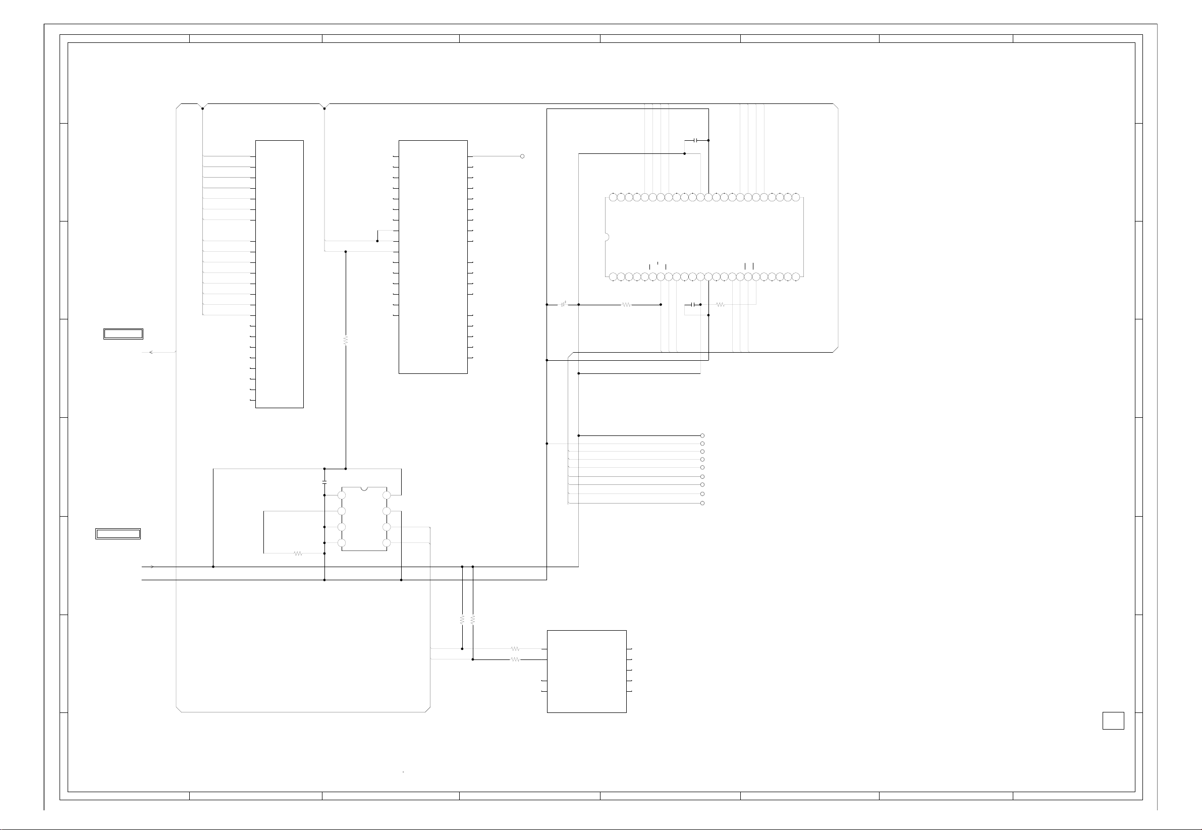
ABC D E F GH
FLASH SCHEMATIC DIAGRAM
8
(DIGITAL PCB)
8
ATSC/CLEAR CABLE ASIC
X240H
IC2401
(6/14 FLASH)
NFCLE
7
6
TO ASIC
DTV_RESET
ROMSCK_NFALE
ROMSO_NFWE#
CS_NF1#
ROMSI_NFRE#
NFRY_BY#
ROMCS_NFCE0#
NFIO0 FAD7_8
NFIO1 FAD9
NFIO2
NFIO3
NFIO4
NFIO5
NFIO6
NFIO7
5
3.3
P30
NFCLE
3.3
N30
NFALE
3.3
N29
NFWEb
3.3
M30
NFCEb(1)
3.3
P29
NFREb
3.3
N28
NFRY_BYb
N27
NFCEb(0)
3.3
H28
NFIO(0)
3.3
J29
NFIO(1)
3.3
J30
NFIO(2)
3.3
K29
NFIO(3)
3.3
K30
NFIO(4)
3.3
L29
NFIO(5)
3.3
L30
NFIO(6)
3.3
M29
NFIO(7)
J27
NFIO(8)
NC
J28
NFIO(9)
NC
K27
NFIO(10)
NC
K28
NFIO(11)
NC
L27
NFIO(12)
NC
L28
NFIO(13)
NC
M27
NFIO(14)
NC
M28
NFIO(15)NC
R2470
10K
ATSC/CLEAR CABLE ASIC
X240H
IC2401
(7/14 FLEX BUS)
G3 D5
FAD(0)
NC
F2
FAD(1)
NC
E1
FAD(2)
NC
G4
FAD(3)
NC
F3
FAD(4)
NC
E2
FAD(5)
NC
D1
FAD(6)
NC
3.3
F4
FAD(7)
3.3
E3
FAD(8)
3.2
D2
FAD(9)
NC
C1
FAD(10)
E4
FAD(11)
NC
D3
FAD(12)
NC
C2
FAD(13)
NC
B3
FAD(14)
NC
C4
FAD(15) FINTR(0)
NC
FCLK
FBE(0)
FBE(1)
FALE(0)
FALE(1)
FSTB
FRDYb
FCEb(0)
FCEb(1)
FCEb(2)
FCEb(3)
FINTR(1)
FINTR(2)
FINTR(3)
FINTR(4)
FRD
FWE
AK11
NFIO7
NFIO6
NFIO5
NFIO4
C2509
000
NCNCNC
0
NCNCNC
IO(4)
NC
CE
RE
NC
3.3
3.3
0
C2508
ROMSI_NFRE#
CS_NF1#
0.1 B
NC
NC
0
0.1 B
0
3.3
VCC
VCC
0
3.3
FCLK
JG2457
C7
NC
D8
NC
A5
NC
B6
NC
A4
NC
NC
D7
NC
C6
NC
B5
A3
NC
B4
NC
C5
NC
D6
NC
H4
NC
F1
NC
NC
G2
NC
H3
NC
C2507
226.3V TZV
000
0
NCNCNC
NC
000
NCNCNC
NC
IO(5)
IO(6)
IO(7)
FLASH MEMORY
NCNCNC
IC2406 HY27US08281A-TP
1 10 11 12 13 14 15 16 17 18 192 20 21 22 23 24
NCNCNC
R2481
2.2K
NC
3
5 6789
NC
/GND
B
SE
NC
R/
0
NC
3.3
00000
NFRY_BY#
VSS
VSS
R2482
000
NCNCNC
NCNCNC
NC
NC
0
10K
333435363738394404142434445464748
CLE
NC
NC
3.3
0
NFCLE
NFIO3
NFIO2
NFIO1
NFIO0
000
0
303132
IO(1)
IO(2)
IO(3)
ALE
WP
WE
0
3.3
3.3
ROMSCK_NFALE
ROMSO_NFWE#
IO(0)
NC
NC
000
NCNCNC
NCNCNC
NC
NC
NC
NC
000
0
7
00
NC
2526272829
NC NCNC
NC
NC
6
5
JG2407
FAD9
4
EEPROM
0.1 B
IC2404 BR24L64F-WE2
C2506
0
1234
0
3.3
FROM POWER2
R2464
3
+3.3V
D_GND
10K
A2
0
VSS
2
3.3
VCCA0
0
WPA1
2.8
SCL
SDA
I2C_CLKA
2.8
I2C_DATA
5678
I2C_CLKA
I2C_DATA
R2484 3.3K
R2485 3.3K
R2592 100
R2593 100
ATSC/CLEAR CABLE ASIC
IC2401 X240H
3.3
AG20
3.3
AK21
NC
AJ20
NC
AH20
ROMCS_NFCE0#
ROMSO_NFWE#
ROMSCK_NFALE
ROMSI_NFRE#
DTV_RESET
(8/14 I2C BUS)
I2CCLKA
I2CDATAA
I2CCLKC
I2CDATAC
FAD7_8
SPI_CLK
SPI_IN
SPI_OUT
SPI_CS0
SPI_CS1
NC
G1
NC
J4
NC
H2
NC
J3
NC
H1
JG2408
JG2409
JG2424
JG2411
JG2412
JG2413
JG2414
JG2415
PCBDH0
CEF169
4
3
2
1
NOTE:THIS SCHEMATIC DIAGRAM IS THE LATEST AT THE TIME
OF PRINTING AND SUBJECT TO CHANGE WITHOUT NOTICE
NOTE:THE DC VOLTAGE AT EACH PART WAS MEASURED
WITH THE DIGITAL TESTER WHEN THE COLOR BROADCAST
WAS RECEIVED IN GOOD CONDITION AND PICTURE IS NORMAL.
1
ABC D E F GH
H-40H-39
Page 73

ABC D E F GH
FRONT END SCHEMATIC DIAGRAM
8
7
ATSC/CLEAR CABLE ASIC
IC2401 X240H
(10/14 DVI)
NC
W3
DVIDATA(0)
NC
W2
6
5
4
DVIDATA(1)
NC
W1
DVIDATA(2)
NC
V1
DVIDATA(3)
NC
V2
DVIDATA(4)
NC
V3
DVIDATA(5)
NC
V4
DVIDATA(6)
NC
U1
DVIDATA(7)
NC
U2
DVIDATA(8)
NC
U3
DVIDATA(9)
NC
U4
DVIDATA(10)
NC
T1
DVIDATA(11)
NC
R2
DVIDATA(12)
NC
R3
DVIDATA(13)
NC
R4
DVIDATA(14)
NC
P1
DVIDATA(15)
NC
P2
DVIDATA(16)
NC
P3
DVIDATA(17)
NC
DVIDATA(18)
P4
NC
DVIDATA(19)
N1
NC
DVIDATA(20)
N2
NC
DVIDATA(21)
N3
NC
DVIDATA(22)
N4
NC
DVIDATA(23)
M1
NC
R1
DVICLK
NC
T2
DVIHSYNC
NC
T3
DVIVSYNC
NC
T4
DVIDE
DVSYDATA(0)
DVSYDATA(1)
DVSYDATA(2)
DVSYDATA(3)
DVSYDATA(4)
DVSYDATA(5)
DVSYDATA(6)
DVSYDATA(7)
DVSCLKA
TDATA(0)
TDATA(1)
TDATA(2)
TDATA(3)
TDATA(4)
TDATA(5)
TDATA(6)
TDATA(7)
TCLKA
TSTRTA
TVLDA
TERA
AJ4
AH5
AG6
AJ3
AH4
AG5
AJ2
AH3
AK3
NC
NC
NC
NC
NC
NC
NC
NC
NC
L2
NC
L3
NC
K1
NC
L4
NC
K2
NC
J1
NC
K3
NC
J2
NC
K4
NC
M4
NC
L1
NC
M3
NC
3
2
FROM POWER2
ATSC/CLEAR CABLE ASIC
(9/14 DVO)
IC2401 X240H
NC
NC
NC
NC
NC
NC
NC
NC
NC
NC
NC
NC
NC
NC
NC
NC
NC
NC
NC
NC
NC
NC
NC
NC
NC
NC
NC
NC
NC
AJ19
AK19
AG18
AJ18
AH18
AG17
AK18
AH17
AG16
AK17
AJ17
AH16
AG15
AK14
AJ14
AH14
AG14
AK13
AJ13
AH13
AK12
AG13
AJ12
AH12
AJ16
AK16
AH15
AJ15
AK15
DVODATA(0)
DVODATA(1)
DVODATA(2)
DVODATA(3)
DVODATA(4)
DVODATA(5)
DVODATA(6)
DVODATA(7)
DVODATA(8)
DVODATA(9)
DVODATA(10)
DVODATA1(1)
DVODATA1(2)
DVODATA(13)
DVODATA(14)
DVODATA(15)
DVODATA(16)
DVODATA(17)
DVODATA(18)
DVODATA(19)
DVODATA(20)
DVODATA(21)
DVODATA(22)
DVODATA(23)
DVOCLK0
DVOCLK1
DVODE
DVOHSYNC
DVOVSYNC
(DIGITAL PCB)
ADC1.8V
ADC1.8V
+3.3V
FDCFE1.8V
C2512 0.1 B
C2513 0.1 B
C2514 10 C
C2515 10 C
B2408
BLM31PG601SN1
B2407
BLM31PG601SN1
C2516
0.1 B
B2409
BLM31PG601SN1
ADC0_AVDD
C2517 0.1 B
ADC1_AVDD
C2518 0.1 B
BLM18BD151SN1
FDC_AVDD
C2520 0.1 B
C2531 0.1 B
C2521 0.1 B
C2532 0.1 B
C2522 0.1 B
B2410
0.1 B
C2533
C2519
VI_REFM
VI_REFP
VIBYPASS1
VIBYPASS0
0.1 B
ATSC/CLEAR CABLE ASIC
(11/14 FRONT END)
IC2401 X240H
VI_IN0
NC
D26
VI_IN1
B26
NC
VI_IN2
NC
C25
VI_IN3
NC
A25
VI_IN4
NC
D30
VI_IN5
NC
C29
VI_IN6
NC
D28
NC
VI_IN7
C27
VI_ATBM
F30
VI_ATBP
E30
0.3
VI_REFM
D24
1.3
VI_REFP
C24
1.2
VI_BYPASS1
E29
1.2
VI_BYPASS0
B28
1.8
ADC0_AVDD
D27
1.8
ADC0_AVDD
C26
1.8
ADC0_AVDD
D25
0
ADC0_AVSS
A26
0
ADC0_AVSS
B25
0
ADC0_AVSS
B27
1.8
ADC1_AVDD
C30
1.8
ADC1_AVDD
E28
1.8
ADC1_AVDD
D29
0
ADC1_AVSS
B29
0
ADC1_AVSS
B30
0
ADC1_AVSS
C28
3.3
VI_AVDD33
A21
FDC_IFP
NC
A23
FDC_IFM
NC
A22
FDC_BYPASS
NC
B23
FDC_REFP
NC
B24
FDC_REFM
NC
A24
1.8
FDC_AVDD
D23
1.8
FDC_AVDD
C21
1.8
FDC_AVDD
D22
0
FDC_AVSS
C23
0
FDC_AVSS
B22
0
FDC_AVSS
C22
0
VI_GUARD
E27
FS_OUTP
FS_OUTN
FS_DVDD
FS_DVSS
FS_AVDD
FS_AVSS
FDC_AGC
FDC_CRX
FDC_DRX
MPEG_D0
MPEG_D1
MPEG_D2
MPEG_D3
MPEG_D4
MPEG_D5
MPEG_D6
MPEG_D7
MPEG_CLK
MPEG_SYNC
MPEG_DATA_EN
MPEG_ERR
FAT_IFP
FAT_IFM
AGC_SDMX
AGC_SDM1
AGC_SDM2
GPIOC(0)
GPIOC(1)
GPIOC(2)
GPIOC(3)
GPIOC(4)
GPIOC(5)
GPIOC(6)
GPIOC(7)
GPIOC(8)
GPIOC(9)
GPIOC(10)
GPIOC(11)
GPIOC(12)
GPIOC(13)
GPIOC(14)
GPIOC(15)
A19
NC
NC
B19
1.8
A18
0
B18
1.8
C19
0
C18
NC
A17
NC
D11
NC
D10
NC
A6
NC
B7
NC
C8
NC
A7
NC
D9
NC
B8
NC
C9
A8
NC
NC
B9
NC
B10
NC
C10
NC
A9
0.7
A28
0.7
X_FAT_IFN
A27
NC
A15
3.3
B15
NC
C15
3.3
D16
3.3
C16
NC
B16
3.3
A16
D17
NC
NC
C17
NC
B17
3.3
A10
NC
C11
3.3
B11
3.3
D12
NC
A11
NC
C12
NC
B12
NC
A12
NC
D13
X_FAT_IFP
X_FAT_IFAGC
C2534
C2535
DNI
0.1 B
0.1 B
FS_DVDD
BLM18BD151SN1
FS_AVDD
BLM18BD151SN1
C2537
0.1 B
390
C2538
R2497
0.1 B
R2495 1K
B2411
B2412
FDCFE1.8V
C2701
0.1 B
FDCFE1.8V
C2702
0.1 B
R2498
100
R2499
100
C2542 0.1 B
FROM/TO AV OUT
T_FAT_IFP
T_FAT_IFN
FAT_IFAGC
X_TUNER_SDA
X_TUNER_SCL
RF_SW
SD-H
AFT_1
AFT_2
8
7
6
5
4
3
2
+3.3V
+1.8V
D_GND
PCBDH0
CEF169
1
NOTE:THIS SCHEMATIC DIAGRAM IS THE LATEST AT THE TIME
OF PRINTING AND SUBJECT TO CHANGE WITHOUT NOTICE
NOTE:THE DC VOLTAGE AT EACH PART WAS MEASURED
WITH THE DIGITAL TESTER WHEN THE COLOR BROADCAST
WAS RECEIVED IN GOOD CONDITION AND PICTURE IS NORMAL.
1
ABC D E F GH
H-42H-41
Page 74

ABC D E F GH
AV OUT SCHEMATIC DIAGRAM
8
1
123
4
1
3456789
101112131415161718
19220
345
(DIGITAL PCB)
678
9
101112131415161718
19220
8
+5V
USBN
FROM/TO FIRM UPDATE
CP2405 YKF45-0036N
USBP
GND
125607220W3
UNREG+5V
FROM/TO TUNER
CP2403
(CP5801)
UNREG+5V
UNREG+4V
UNREG+4V
UNREG+4V
GND
REG +5V
GND
Y OUT
U OUT
GND
GND
V OUT
GND
GND
CVBS OUT
AUDIO MUTE-L
SD-H
AFT_1
7
C2608
47P CH
V[PR]_OUT
B2413 BLM18BD102SN1
B2414 BLM18BD102SN1
SD-H
CVBS_OUT
B2415 BLM18BD102SN1
AFT_1
AT+5V
USB_N_A
USB_P_A
R2533 15K
R2534 15K
C2630
0.1 B
C2606 0.1 B
C2605 0.1 B
B3406 BLM31PG601SN1
B3407 BLM31PG601SN1
UNREG+5V
B3408 BLM31PG601SN1
UNREG+4V
UNREG+4V_M
B3410 BLM18BD151SN1
AT+5V
Y_OUT
U[PB]_OUT
6
LEVEL_SHIFT
Q2407 KTK5132E
S
I2SCLK_INC
LEVEL_SHIFT
5
I2SWS_INC
I2SDATA_INC
+3.3V
LEVEL_SHIFT
Q2401 KTK5132E
1.5 1.0
3.3
Q2404 KTK5132E
D
G
3.3
S
D
G
R2506
3.3K
D
2.33.3
G
3.3
S
1.72.6
3.3K
R2514
R2516
3.3K
ATSC/CLEAR CABLE ASIC
(12/14 I2S AUDIO)
IC2401 X240H
3.3
AG7
I2SSCK_INC
3.3
I2SWS_INC
AH6
3.3
I2SSD_INC
AJ5
NC
I2SSCK_IND
AK4
NC
I2SWS_IND
AJ6
NC
I2SSD_IND
AK5
I2SSOSCK_OUTA
I2SSOSCK_OUTB
4
X_TUNER_SDA DAC6_B
X_TUNER_SCL TRSET
100
TUNER_SCL
TUNER_SDA USBA_N
3
FROM/TO POWER2
DTV_ON-H
UNREG+5V
UNREG+4V_M
2
UNREG+4V
AT+5V
+3.3V
+1.8V
+2.6V
D_GND
TWIRE_TXDC DAC_AVDDQ DAC_AVDDQ USBB_P
TWIRE_RXDC USBB_N
RX_[X240]
TX_[X240]
R2441
100
R2440
LEVEL_SHIFT
Q2403
KTK5132E
R2508
4.7K
R2509
4.7K
3.3
S
3.3
G
D
3.3
LEVEL_SHIFT
Q2406
KTK5132E
R2515
4.7K
B2417
BLM18BD151SN1
R2512
4.7K
3.3
S
3.3
G
D
3.3
VDDC_1.8V
DAC_2.5V
10 C
C2551
C2552
B2419
BLM18BD151SN1
B2418
BLM18BD151SN1
B2416
BLM18BD151SN1
10 C
125607220W3
AFT_2
CP2404
(CP5802)
C2609
47P CH
C2611
C2623
47P CH
47P CH
C2612
C2624
47P CH
47P CH
B2427 BLM18BD102SN1
AFT_2
I2SWS_OUTA
I2SSCK_OUTA
I2SSD_OUTA
I2SWS_OUTB
I2SSCK_OUTB
I2SSD_OUTB
SPDIF_OUTA
1B
C2554
1B
C2555
1B
C2556
C2553
1B
GND
GND
RF_SW
TU I2C CLK
TU I2C DATA
B2423 BLM18BD102SN1
B2424 BLM18BD102SN1
B2421 BLM18BD102SN1
B2422 BLM18BD102SN1
RF_SW
TUNER_SDA
TUNER_SCL
FAT_IFAGC
(13/14 VIDEO ENCODER)
VDDDI
VSSDI
AVDDQ
AVSSQ
A1VDD
A1VDD
AVSSN
AVSSN
IF AGC
IF OUT2
IF OUT1
T_FAT_IFP
T_FAT_IFN
HSYNC_OUT
VSYNC_OUT
HSYNC2_OUT
VSYNC2_OUT
COMP
RSET
C_R
Y_G
COMP_B
R2SET
VDD2DI
VSS2DI
A2DDQ
A2VSSQ
A2VDD
A2VDD
A2VSSN
A2VSSN
C2621 47PCH
AJ8
AH9
AG10
AK8
AC2
G
AC1
B
AD2
AD1
AE1
AB2
AA2
AA1
AB1
AA4
AB4
AC4
AA3
AB3
C2622 47PCH
NC
NC
NC
NC
1.1
DAC0_R
1.1
DAC1_G
1.1
DAC2_B
0
DAC3_COMP
1
QRSET
0
DAC4_R
0
DAC5_G
0
1
1.8
Y2
1.8
Y1
1.8
Y3
0
2.6
2.6
0
0
C2573
C2574
C2575
R2529
680
R2532
680
0.1 B
0.1 B
0.1 B
C2576
R2528 33
R2409
33
R2530 33
R2531 33
R2410
33
0.1 B
R2538 4.7
USB_P_A
R2535 15K
R2536 15K
R2539 4.7
R2540 4.7
USB_N_A
USB_P_B
R2523
R2521
75 +-1%
R2520
75 +-1%
R2522
R2541 4.7
+3.3V
USB_N_B
75 +-1%
75 +-1%
C2562
C2561
C2564
47P CH
C2563
NLV25T
L2414
0.47uH
47P CH
NLV25T
L2412
0.47uH
47P CH
NLV25T
L2411
0.47uH
NLV25T
L2413
0.47uH
47P CH
ATSC/CLEAR CABLE ASIC
IC2401 X240H
0
USBA_P
AH23
0
AG22
0
AK24
0
AJ23
R2537
3.3
AK23
100K
NC
AG19
NC
AK20
NC
AH19
NC
A13
NC
D14
34
C2572
47P CH
33
R2525
C2570
47P CH
35
R2524
C2569
47P CH
36
C2571
47P CH
(14/14 USB/SERIAL)
USBPA
USBNA
USBPB
USBNB
USB_OVRCUR
IRRXDA
IRTXDA
IRBIDB
CAPT1
COMP1
R2527
75 +-1%
R2526
CTSAb
RTSAb
75 +-1%
RDA
TDA
RDB
TDB
RDC
TDC
75 +-1%
75 +-1%
AJ21
AH21
AK22
AG21
AJ22
AH22
V[PR]_OUT
U[PB]_OUT
CVBS_OUT
NC
NC
NC
NC
TWIRE_TXDB
3.3
C13
B13
TWIRE_RXDC
3.3
TWIRE_TXDC
I2SSDO_OUTA
I2SWS_OUTA
I2SSCLK_OUTA
C2625 47PCH
I2SDATA_OUTA
I2SCLK_OUTA
I2SWS_OUTA
R2518 22
R2519 22
R2517 22
C2558
0.1 B
C2559
0.1 B
C2560
0.1 B
I2SSDO_IN
I2SSCLK_IN
I2SDATA_INC
I2SCLK_INC
I2SWS_INC
ATSC/CLEAR CABLE ASIC
IC2401 X240H
AE2
AF3
AC3
AD4
AE4
AF4
AD3
AE3
RX (X240)
TX (X240)
DTV_RESET
DTV POWER
SPDIF OUT
NC
B2425 BLM18BD102SN1
B2426 BLM18BD102SN1
DTV_RESET
DTV_ON-H
SPDIF_OUTA
TX_[X240]
RX_[X240]
3.3
AK9
3.3
AH10
NC
AJ10
3.3
AG11
NC R
AK10
NC
AH11
NC
AJ11
NC
AG12
B2420
BLM18BD151SN1
3.4
AJ9
DAC_VDDI DAC_VDDI
DAC1_AVDD DAC2_AVDD TWIRE_RXDB
C2557
0.1 B
I2SWS_IN
Y_OUT
FROM/TO FRONT END
T_FAT_IFP
T_FAT_IFN
FAT_IFAGC
X_TUNER_SDA
X_TUNER_SCL
RF_SW
AFT_1
AFT_2
SD-H
TO ASIC
DTV_RESET
PCBDH0
CEF169
7
6
5
4
3
2
1
NOTE:THIS SCHEMATIC DIAGRAM IS THE LATEST AT THE TIME
OF PRINTING AND SUBJECT TO CHANGE WITHOUT NOTICE
NOTE:THE DC VOLTAGE AT EACH PART WAS MEASURED
WITH THE DIGITAL TESTER WHEN THE COLOR BROADCAST
WAS RECEIVED IN GOOD CONDITION AND PICTURE IS NORMAL.
1
ABC D E F GH
H-44H-43
Page 75

ABC D E F GH
POWER2 SCHEMATIC DIAGRAM
8
(DIGITAL PCB)
+-1%
1.2K
R3410
5.6K
R3411
+-1%
7
R3412
C3409
12K +-1%
15P CH
R3413
R3429
100
0.001B
C3408
1B
C3410
6
4.7K
R3405
10K
R3401
2.9
SW
3.3K
Q3403
KTC3875S_Y_RTK
R3406
4.5
0
0
0
SW
Q3404
KRC103SRTK
0
C3407
4706.3V CV-EX
5
1.2
1
0.8
2345678
3.3
0
0
R3414
DC/DC CTL
IC3401
AL1042
5.6
DUAL FET
Q3405 SP8K3
2.7 1.3 3.5 0
15K
3.3
2.9
3.3
100
R3430
551.31.3
5678
D1
D2
D2
G1
S2
G2
1.3
10.3
0.1
5.4
0
5.1
5.2
10 11 12 13 14 15 16
5.2
9
D1
S1
1234
C3412
C3411
W808
D3407
RB520S-30-TE61
10 B
C3413
ELLCTV4R7N
B3401
BLM18PG330SN1D
D3408
RSX301L-30
L3401
4.7uH
R3427
0.047
1/4W
R3428
0.047
1/4W
BLM31PG391SN1L
1502V CD
C3415
B3402
C3416
TO ASIC
CORE_1.2V
1006.3V TZV
CORE_1.2V
+1.8V
+3.3V
D_GND
TO FLASH
+3.3V
D_GND
TO FRONT END
+3.3V
+1.8V
D_GND
0.22 B
10 B
8
7
6
5
5.25.2
POWER_SW
Q3407
5.3
KRA101SRTK
4
FROM/TO AV OUT
UNREG+5V D_GND
3
UNREG+4V_M
UNREG+4V
AT+5V
DTV_ON-H
D_GND D_GND
+3.3V +3.3V
+1.8V +1.8V
+2.6V +2.6V
POWER_SW
Q3406
KRC103SRTK
3.1
5.3
0
2
+5V
R3432
220
C3418
12 456
0.1 B
C3419
REG+3.3V
IC3402 BA00BC0WFP
03.343.18 1.26
R3418
1006.3V SJV
C3420
0.1 B
DH
1K +-1%
V_ADJV_OUTV_INV_C GND
R3419
R3420
39
560 +-1%
C3421
D3402
D3406
0.1 B
EC31QS04
EC31QS04
C3423
REG+1.8V
IC3403 BD7820FP
5.6K
R3433
12 456
3.253.18
4716V SJV
C3424
2206.3V SJV
C34251BC3426
0.1 B
DH
1.8K
R3434
V_ADJV_OUTV_INV_C GND
1.25
0
1.8
R3421
1K +-1%
R3423
R3422
680 +-1%
10
C3428
3306.3V TZV
C3429
0.1 B
C3430
REG+2.6V
IC3404 BA7810HFP
GNDEN Vin Vout Vadj
12345
3.18 4
C3432
0.1 B
C3431
6
0 1.272.6
1006.3V SJV
R3424
1B
1K +-1%
R3425
R3426
120
820+-1%
D3403
EC11FS2-TE12L
D3404
EC11FS2-TE12L
D3405
EC31QS04
C3434
0.1 B
C3435
4
TO AV OUT
+3.3V
+1.8V
+2.6V
+3.3V
+1.8V
+2.6V
3
2206.3V SJV
TO SDRAM
2
NOTE:THIS SCHEMATIC DIAGRAM IS THE LATEST AT THE TIME
1
OF PRINTING AND SUBJECT TO CHANGE WITHOUT NOTICE
ABC D E F GH
NOTE:THE DC VOLTAGE AT EACH PART WAS MEASURED
WITH THE DIGITAL TESTER WHEN THE COLOR BROADCAST
WAS RECEIVED IN GOOD CONDITION AND PICTURE IS NORMAL.
CAUTION
:SINCE THESE PARTS MARKED BY
CRITICAL FOR SAFETY,USE ONES
DESCRIBED IN PARTS LIST ONLY
ARE
ATTENTION
:LES PIECES REPAREES PAR UN ETANT
DANGEREUSES AN POINT DE VUE SECURITE
N’UTILISER QUE CELLS DECRITES
DANS LA NOMENCLATURE DES PIECES
PCBDH0
CEF169
CAUTION: DIGITAL TRANSISTORCAUTION: DIGITAL TRANSISTOR
1
H-46H-45
Page 76

8
7
6
5
4
3
2
1
H-47
FROM/TO AC INLET
J502
12
CCT2302-0911
6.3A 125V
ABC D E F GH
FH501
EYF-52BCY
CP514
4
12
D501
1H3-E
RELAY DRIVE
Q501
KTC3198
AT+5V
7A 250V
6.3A 125V
6.3A 125V
F501
6.3A125V
EYF-52BCY
1
003P-2100
3
RY501
ALKS329_A60
0.6
R502
C501
2216V KA
R503
R501
2.7K 1/4W
R504
P.CON+5V
GND
ATTENTION
D504_2
D505
FH502
D503
0.7
0
10K1/4W
REGULATOR
IC501
KIA431A-AT
REF
123
2.5
R506
C502
0.0047 B
270 +-1%
2.7K +-1%
R505
9.8
0
10K +-1%
PROTECT
Q502
KRC102SRTK
CAUTION
CAUTION
SH501
TP00385-21
DSS-302M
ENE271D-10A
1
CP504
003P-2100
COIL,LINE FILTER
L506
SS30V-R250092
34
R507
C503
0.22275V ECQUL
1.5M 1W
12
ENE241D-10A-Q6
4
RM11C-EIC
17W
R600
RM11C-EIC
ANODE
CATHODE
9.8
0
R508
C504
2.2K
100 1/4W
0.1 B
R509
1.7
0
PROTECT
KTA1504S_Y_RTK
10K
1.70
D506
R510
MTZJ2.2B
Q503
:FOR CONTINUED PROTECTION AGAINST FIRE HAZARD,
REPLACE ONLY WITH THE SAME TYPE FUSE
AND 7A 250V(F502)
:POUR UNE PROTECTION CONTINUE LES RISQUES D’INCEIE
N’UTILISER QUE DES FUSIBLE DE MEME TYPE
ET 7A 250V(F502)
COIL,LINE FILTER
2
3
D508
D509
150
R512
R513
100 1/4W
1K
CHASSIS GND
ECQUL
275V
C507
0.1
SS30V-R250092
W825
TH501
1
D507
RBV-608
763WAAA143
D510
RM11C-EIC
D511
RM11C-EIC
763WAAA142
11.9
10.8
1K
R514
R515
100
C505
UNREG+12V
UNREG+6V
:F503 IS MANUFACTURED BY SKYGATE CO.,LTD, TYPE 20N.
SH502
TP00385-21
C506
0.0015250V KX
34
12
L507
R520
R517
27K 1/4W
27K 1/4W
CP513
003P-2100
1
NTPAN3R0LDKB0
HS501
R525
10K
HS502
FEED BACK
IC511
PS2561AL1-1-V(W)
1
2
10016V MHE
R518
4.7K 1/4W
D513
D512
1SS133
1SS133
SOUND+B
C509
0.22275V ECQUL
CP505
003P-21001
1/4W
C511
R519
15K 1/4W
20.5
8.9
34
100
R521
D514
MTZJ5.6B
7.5
0
6.3A 125V(F501)
POWER_SW_CTL
IC502 STR-X6737
S S VCC SS/OLP FB OCP/BDD
1234567
380 0.5 0.5 19.5 1.0 0.8
0.00182KV R
C513
R524
R527
0.27 1W
590200V EE
C510
R529
100200V ED
100200V ED
C583
R522
15K 1/4W
R523
15K 1/4W
R526_1
1K1/4W
ST-BT_CTL
0
Q505
KRC102SRTK
0.1
C516
C514
470PCH
0.27 1W
0.22 1W
POWER_SW_CTL
IC503
STR-W6735
D S VCC SS/OLP FB OCD/BD
1 34567
380
R
680P2KV
C515
D515
MTZJ6.2B
R530
0.22 1W
IS THE LIVE CONNECTIONCAUTION:
ST-BY_H
6.3A 125V(F501)
150V YXF
R531
1K
0.01 B
C517
B501
W4BRH3.5X6X1.0X2
0
20.5
C518
470P B
R534
C521
D516
1SS133
R532
100 1/4W
0.1 1.0 0.8
R533
C585
0.22 B
150V YXF
C519
C520
T502
81420774
20N_7000FSW
ECWF
0.039400V
R541
D522
D523
YXF
R542
250
170
D524
170
250
250
380
NC
0
18
22 1/2W
345
380
250
20
0
NC
10 1/2W
1H3-E
8
7
6
5
3
2
1
19.5
8
7
6
4
3
2
1
8.4
T501
81350964
IC512
PS2561AL1-1-V(W)
34
C530
220P250V KX
C529
470P250V KX
UNREG+6V
UNREG+12V
20.7
1
19.6
2
10
11
12
13
14
15
16
SH503
TP00385-21
SH504
TP00385-21
D525
1SS133
10
11
12
13
14
15
16
9
D526
ECWF
0.039400V
C523
100K 2W
R
220P2KV
D518
B502_1
W4BRH3.5X6X1.0
C522
D517
MTZJ6.2B
1K
D519
1SS133
0.01 B
R535
NOTE:THIS SCHEMATIC DIAGRAM IS THE LATEST AT THE TIME
NOTE:THE DC VOLTAGE AT EACH PART WAS MEASURED
F502
RU3AM
7A 250V
R536
D521
1K 1/4W
1SS133
0.0047 B
YXF
4.750V
C525
R540_1
1K1/4W
R537
C527
100K 2W
D520
SARS01-V1
R538
1K 1/4W
1SS133
C524
0.01 B
1H3-E
4.750V
C526
100 1/4W
OF PRINTING AND SUBJECT TO CHANGE WITHOUT NOTICE
WITH THE DIGITAL TESTER WHEN THE COLOR BROADCAST
WAS RECEIVED IN GOOD CONDITION AND PICTURE IS NORMAL.
9
W801
NC
NC
12
0
0
6
6
12
NC
24
24
NC
NC
0
0
NC
R543
W805
W804
1SS133
D527
FMX-22S
FMX-22S
1.5K1/4W
C531
1SS133
SOUND+B
D530
D531
763WAAA142
220P2KV R
D528
FMX-22S
1
2
3
HS503
763WAAA070
D529
1H3-E
HS505
763WAAA145
C532
220P2KV R
1
2
3
1
3
HS504
CATHODE
19.6 0 2.4
C534
0.15 B
C533
0.1 B
C535
YG862C15R
D532
RB085T-40
1
3
R544
C542
120035V FM
2
120035V FM
C539
R545
2.2K 1/4W
REGURATOR
IC504
KIA431A-AT
ANODE
R548
100025V FM
D533
1
3
220P R
2
C538
1001/4W
R546
1K 1/4W
ON/OFF VIN GND VOUT
12345
C541_1
REF
123
10K
DTV+5V SW
C540
C543
2
C536
220010V
C537
2.250V MHE
D534
MTZJ27B
5V_REGULATOR
5.92.5
10016V MHE
R550
R551
R552
R547
3.0
Q515
KRC102SRTK
100025V FM
W824
21DQ09N
100016V FM
C545
L501
22uHTSL0808
FM
R549
3.9K1/4W
IC505
BA7810T-V5
C544
CAUTION
ATTENTION
RCH8011NP-6R8L
L503
6.8uH
W818
W820
2.2K
R563
BACKLIHGTON
LIGHT_CTL
22K+-1%
1.8K +-1%
2.7K +-1%
1K
0
DTV+5V SW
0
KRC102SRTK
D535
FM
1000
16V
L502
6.8uH
RCH8011NP-6R8L
R553
22K
4.2
5.1 1.250
C546_1
0.1 B
:SINCE THESE PARTS MARKED BY
CRITICAL FOR SAFETY,USE ONES
DESCRIBED IN PARTS LIST ONLY
:LES PIECES REPAREES PAR UN ETANT
GND
P.CON+5V
AT+5V
R559
10K
R555
1K
4.5
0
0
Q507
W806
W821
D545
1N4005-EIC
22016V MHE
C548
C547
22016V MHE
5.0
5.0
24
VADJ
R557
390
R556
1K
R558
+-1%
2.7K
+-1%
+-1%
10016V MHE
DANGEREUSES AN POINT DE VUE SECURITE
N’UTILISER QUE CELLS DECRITES
DANS LA NOMENCLATURE DES PIECES
FM
120035V
C549
1050V MHE
C550
C552
W822
C555
68016V FM
C554
0.1 B
C557 0.1 B
C556
0.01 B
R564
7
G
12
12
12
SSS
1234
Q504 RSS050P03
5V_REGULATOR
IC506
BA00BC0WCP-V5
12345
R561
1001/4W
10016V
C558_1
POWER_FAIL
Q508
KTA1504S_Y_RTK
W823
P.CON+5V
TO INVERTER PCB
C553
0.01 B
R567
100
0.1 B
R572
0.047 1/4W
R573
0.047 1/4W
R574
0.047 1/4W
DTV 5V CONTROL
IC509 AL1015
11.9
1234
VIN CS
4.5
V5/PWOH
2.5
VREF
2.5
33K
C559
27PCH
11.95
DDD
5678
11.95
11.95
D
11.95
P.CONSW
MHE
24
GNDVINON/OFF
VOUT VADJ
C562_1
10016V MHE
C563 0.1 B
R5761001/4W
VIN VOUT G FB ON/OFF
12345
11.8 5.1 0
D538
1SS355
68016V FM
C560
HS506
R568
R571
8.2K
4.7K
ARE
CP506
A2001WV2-14P
1
+24V
2
+24V
3
+24V
4
+24V
5
+24V
6
GND
7
GND
8
GND
9
GND
10
GND
FBCC
6.0
22K
R580
+-1%
24
1K +-1%
11
12
13
14
11.9
C566
11.9
5.0
0
1.25
5678
R584
1K +-1%
0
0.7
P.CONSW
Q511
R582
KTC3875S_Y_RTK
22K1/4W
D502
D539
270 +-1%
C567_1
C564
0.15 B
D540
R583
2.7K +-1%
R585
2.7K
+-1%
21DQ09N
EC31QS04
11.2
R590
4.7K
L504
33uH7313N
EC31QS04
NC
BL ON/OFF
Brightness Ctl
NC
SIGNAL GND
EXT
GND
W816
R578
1.255.0012.012.0
R577
2.7K
R575
1K+-1%
5V_REGULATOR
IC508
LA5774-E
1.3 6.8
R579
763WAAA070
CAUTION: DIGITAL TRANSISTOR
POWER3 SCHEMATIC DIAGRAM
(POWER PCB)
CD505
CU2E5101
DC/DC SW
Q512
2SJ650
5.0
S
D
G
5.0
0.01 B
24
R586
B505
BLM18PG121SN1D
R588
D541
470
EC31QS04
+-1%
HS507
763WAAA070
0.47 B
C582
9V_REGULATOR
IC510
PQ090RDA1SZH
09.0
10016V MHE
BLM18PG181SN1D
BLM18PG181SN1D
6.5
68016V FM
C568
+-1%
4.750V
GND
B506
B507
0
PCB240
CEF171
C565
VIN VOUT ADJ
1234
C569_1
10016V MHE
560
L505
10uH7313N
B508
BLM18PG121SN1D
D542
EC31QS04
MHE
R587
2.2K
1.25
R591
LCD5V_SW
Q513
KTC3875S_Y_RTK
R594
0
0
LCD5V_SW
0
Q514
KRC102SRTK
4.7K
4.7K
C572
R589
R595
1K
C571
0.1 B
3.0
D543
SR340-004
C573
68016V FM
10K
R592
100
P.CON+5V_LCD
DTVUNREG+4V
DTV+5V
0.1 B
GND_DTV
SOUND+B
AT+12V
SOUND_GND
GND
P.CON+9V
P.CON+12V
UNREG+12V
AT+5V
POWER_ON-H
P.CON+9V
POWER_FAIL
AT+5V
LCD-H
GND_DTV
1000
C584
DTV+5V
GND
AT+12V
P.CON+9V
C574
0.1 B
P.CON+5V_LCD
P.CON+5V
C575
0.1 B
P.CON+12V
GND
ST-BY_H
SOUND+B
SOUND_GND
POWER_FAIL
LCD-H
AT+5V
GND
BACKLIHGTON
LIGHT_CTL
POWER_ON-H
TR504
W5T29X7.5X19
CD508
CD010701
CD507
CD010701
C581
6.3V MHE
C577
0.1 B
C578
0.1 B
C576
0.1 B
NC
0.1 B
C580
TR507
W5T29X7.5X19
FROM/TO POWER
(CP3808)
CP508
A2001WV2-7P
GND
GND
GND
0.1 B
DTV UNREG+4V
DTV UNREG+4V
DTV UNREG+5V
DTV UNREG+5V
FROM/TO REGULATOR2
CP509
(CD501)
A2001WV2-4P
GND
GND
DVD+12V
DVD+12V
FROM/TO POWER
CP510
(CP3802)
A2501WV2-2P
9VSC
GND
FROM/TO POWER
CP511
(CP3803)
A2501WV2-12P
5V SC
5V SC
5V SC
GND
GND
GND
12VSC
12VSC
GND
GND
ST-BY_H
INVETER_DET
FROM/TO POWER
CP512
(CP3801)
A2501WV2-4P
SOUND+B
SOUND+B
SOUND GND
SOUND GND
FROM/TO POWER
CP507
(CP3804)
A2501WV2-7P
POWER_FAIL
LCD-H
AT+5V
GND
BACKLIGHT ON
LIGHT_CTL
POWER ON-H
8
7
7
6
5
4
6
3
2
1
4
3
2
1
5
1
2
1
2
4
3
4
5
6
7
8
9
10
11
12
3
1
2
3
4
1
2
3
2
4
5
6
7
1
ABC D E F GH
H-48
Page 77

ABC D E F GH
8
OPERATION/REMOCON/FILTER/AC INLET SCHEMATIC DIAGRAM
8
(REMOCON PCB)
FROM/TO AV SWITCH2
7
6
5
Vout
1
GND
2
B+
3
ROM-V338TAO
OS2200
R2207
471/4W
G
R
1006.3V KA
C2207
STANDBY/POWER
D544
LTL-1BEFJ-002A
(OPERATION PCB)
R2205
390
CD4202
CP2201
(CP4202)
A2001WR2-5P
REMOCON IN
GND
AT+5V
STANDBY LED
POWER ON LED
PCBDA0
CEF182
FROM/TO JACK
CP2203
A2001WR2-3P
KEY A
CU256001
(CP2200)
KEY B
GND
1
2
3
4
5
3
2
CD2201
1
CU235502
7
6
5
C2209
EVQ21505R
R2206
820
SW2205
EVQ21505R
POWER ON/OFF
SW2202
VOL DOWN
EVQ21505R
R2204
SW2203
VOL UP
4
SW2201
EVQ21505R
INPUT SELECT
R2201
5.6K
CH UP
SW2204
CH DOWN
EVQ21505R
R2202
2.2K
SW2206
EVQ21505R
R2203
1.2K
0.01 B
C2204
0.01 B
390
3
2
NOTE:THE DC VOLTAGE AT EACH PART WAS MEASURED
WITH THE DIGITAL TESTER WHEN THE COLOR BROADCAST
WAS RECEIVED IN GOOD CONDITION AND PICTURE IS NORMAL.
NOTE:THIS SCHEMATIC DIAGRAM IS THE LATEST AT THE TIME
OF PRINTING AND SUBJECT TO CHANGE WITHOUT NOTICE
1
FROM/TO OPERATION2
CD2251
(CP2251)
CU220702
KEY 1
GND
PCB270
CEF185
2
1
4
3
2
CAUTION
:SINCE THESE PARTS MARKED BY
CRITICAL FOR SAFETY,USE ONES
DESCRIBED IN PARTS LIST ONLY
ARE
ATTENTION
:LES PIECES REPAREES PAR UN ETANT
DANGEREUSES AN POINT DE VUE SECURITE
N’UTILISER QUE CELLS DECRITES
DANS LA NOMENCLATURE DES PIECES
1
H-49
ABC D E F GH
H-50
Page 78

ABC D E F GH
MPEG/MICON/DSP/RF_AMP SCHEMATIC DIAGRAM
8
(DVD MT PCB)
8
7
FROM/TO MEMORY
6
5
4
3
RAMCS0#
RAMRAS#
2
RAMCAS#
HA0
HA1
HA2
HA3
HA4
HA5
HA6
HA7
HA8
HA9
HA10
HA11
HA12
HA13
HA14
HA15
HA16
HA17
HA18
HA19
HD0
HD1
HD2
HD3
HD4
HD5
HD6
HD7
HD8
HD9
HD10
HD11
HD12
HD13
HD14
HD15
MEMCS0
RD
WR
SD_A0
SD_A1
SD_A2
SD_A3
SD_A4
SD_A5
SD_A6
SD_A7
SD_A8
SD_A9
SD_A10
SD_D0
SD_D1
SD_D2
SD_D3
SD_D4
SD_D5
SD_D6
SD_D7
SD_D8
SD_D9
SD_D10
SD_D11
SD_D12
SD_D13
SD_D14
SD_D15
SD_BA0
RAMDQM
RAMWE#
RAMCLK
RAMCKE
JG001
JG002
JG003
JG004
JG005
JG006
JG007
JG008
JG009
D4008
FROM/TO AUDIO/VIDEO
SYS_MUTE
DAC_VIDEO_C
DAC_VIDEO_B
ASDATA0
ABCLK
ALRCLK
AMCLK
MD
MC
ML
RESET
SPDIF
DUPRD1
RX/RDY[I/O[0]]
FROM/TO MOTOR DRIVE
VDDPWM3.3V
TRAY_OPEN
TRAY_CLOSE
HOME
TOUT_SW
TIN_SW
DVD_CD
DRVSB
RF
OPU_A
OPU_B
OPU_C
OPU_D
OPU_E
OPU_F
VC
SPDL_SENSSPDL_SENS+
DVD/CDPD
DVD_LD
CD_LD
SPINDLE_PWM
SLED_PWM
TRACK_PWM
FOCUS_PWM
GND
FROM/TO REGULATOR2
P.CON+3.3V_D
P.CON+5V_D
P.CON+1.8V_D
GND
(GND,D_GND)
7
6
5
(RF_GND)
4
3
2
C4038
0.01 B
BOOT2
BOOT1
D4005
DUPTD1
1SS355
DUPRD1
DUPTD0
DUPRD0
P.CON+5V_D
4.7K
R4039
4.7K
R4037
4.7K
R4038
4.7K
C4105 10P CH
R4036
R4032
4.7K
R4054
1K
R4053
1K
C4008
C4016 0.1 F
C4017 0.1 F
BOOTSEL1
BOOTSEL2
HA15 DAC_VIDEO_C
HA16 DAC_VIDEO_B
HA14 DAC_VIDEO_D
HA13
HA12 DAC_VIDEO_E
HD15
HA11
HD7
HA10 P-H/I-L
HD14
HA9
HD6
HA8
HD13
HD5
HD12
WR ML
HD4 I2C_CLK MC
HD11
HD3 D1_2
HA19 D1_1
HD10
HA18
HD2
HA17
HD9
HA7
HD1
HA6
HD8 IAMCLK AMCLK
HA5
HD0 IALRCLK ALRCLK
HA4
RD ASDATA0
HA3
HA2
MEMCS0 SPDIF
HA1 MIC_ON
HA0
0.1 F
0.1 F
C4013
0.1 F
C4014
0.1 F
JG032
C4010
C4077
R4065 4.7K
R4052
4.7K
R4051
4.7K
R4078
4.7K
R4087
4.7K
3.3
3.3
NC
3.3
3.0
3.0
3.0
3.3
3.3
0.5
2.6
NC
0.1 F
DUPTD1
JG030
JG029
IRRCV
FPCSTRB
R4089
4.7K
3.3
3.3
3.3
110
SSCRXD
MEMCS(1)
3
VDDP
4
MEMAD(15)
5
MEMAD(16)
MEMAD(14)
MEMAD(13)
MEMAD(12)
0
MEMDA(15)
MEMAD(11)
MEMDA(7)
111213141516171819 22021222324
0
GNDP
0
MEMAD(10)
1.9
MEMDA(14)
0
MEMAD(9)
0
MEMDA(6)
0
MEMAD(8)
2.1
MEMDA(13)
2.0
MEMDA(5)
0
MEMAD(20)
3.3
VDDP
0.6
MEMDA(12)
3.3
MEMWR#
2.6
MEMDA(4)
1.8
VDDC
2526272829
2.7
MEMDA(11)
2.9
MEMDA(3)
0
MEMAD(19)
0
GNDC
0.5
MEMDA(10)
30313233343536373839
0
MEMAD(18)
0
GNDP
0.6
MEMDA(2)
0
MEMAD(17)
0.6
MEMDA(9)
2.7
MEMAD(7)
2.7
MEMDA(1)
0.6
MEMAD(6)
0.4
MEMDA(8)
5.5
MEMAD(5)
40414243444546474849
3.3
VDDP
0.4
MEMDA(0)
3.3
MEMAD(4)
0
MEMRD#
0
MEMAD(3)
0
MEMAD(2)
3.1
MEMCS(0)#
3.1
MEMAD(1)
3.2
MEMAD(0)
0
GNDP
50
3.3
VDD-IP
5152
3.3
VDDP
53 545556 57 58 59660 61 62 63 64 65 66 67 68 69770 71 72 73 74 75 76 77 78 79880 81 82 83 84 85 86 87 88 89990 91 92 93 94 95 96 97 98 99
0.9
0.3
1.001.0
10010V YK
C4078_1
DUPRD1
DUPTD0
1SS355
D4003
W859
3.3
3.3
DUPRD0
FOCUS_PWM
D4002 1SS355
R4063
1.7
3.3
DUPRD0
DUPTD0
PWMCO(0)
RAMADD(1)
RAMADD(6)
VDDP
3.301.0
C4018 0.1 F
JG023
SPINDLE_PWM
B4009
MMZ1608R102CT
C4001
0.0039 B
B4014
FS1
FS2
MMZ1608R102CT
C4002
0.1 F
15K
R4061 11K
0
0
2.3
3.3
VDDPWM
GPCI/O(46)
IDGPCI/O(4)
208
SSCTXD
207
SSCCLK
206
DUPTD1
205
DUPRD1
53
RAMADD(4)
54
RAMADD(3)
55
RAMADD(5)
56
RAMADD(2)
RAMADD(0)
GNDP
RAMADD(7)
0.200.2
SLED_PWM
B4011
MMZ1608R102CT
C4003
SGND
R4060 11K
0
1.7
GNDPWM
PWMCO(3)
PWMCO(4)
VDDC
RAMADD(10)
RAMADD(8)
1.8
1.900.2
0.1 F
C4019
TRACK_PWM
TRAY_OPEN
TRAY_CLOSE
B4012
C4056
0.027 B
0.027 B
R4062 39K
0
0
1.7
PWMCO(2)
SLEDPULSE
SPINDLEPULSE
RAMADD(9)
VDDP
GNDC
3.303.1
NC NC
0.1 F
C4020
MMZ1608R102CT
W840
C4033 0.1 F
0
3.2
3.3
VDD-IP
ICGPI/O(6)
ICGPI/O(7)
RAMADD(11)
RAMBA(0)
RAMCS(0)# RAMBA(1)
0.503.1
DVD_CD
(DVD-L/CD-H)
B4013
MMZ1608R102CT
C4057
180P CH
B4016
0
0
3.3
GNDP
IDGPCI/O(3)
GNDP
RAMCS(1)#
0.2
TIN
DRVSB
TOUT_SW
(MUTE-L)
C4096
0.001
B
C4032
0.001
B
C4088 0.1 F
C4068 1006.3V KA
MMZ1608R102CT
0
0
1.8
3.3
3.2
VDDC
GNDC
VDDP
GPCI/O(32)
ICGPCI/O(4)
ICGPCI/O(5)
MPEG/MICON/DSP/RF_AMP IC
IC4001
ZR36862PQCG-B
RAMWE#
RAMDQM
GNDPCLK
VDDP
RAMCAS#
RAMRAS#
0
0
3.2
3.3
3.2
W810
R4059 100
0
AGND1
PCLK
1.5
100
R4008
DVD_LD
0
2.3
AGNDREF
VDDPCLK
3.3
2.101.3
100
C4022 0.1 F
R4064
CD_LD
3.300.2
DVD_LD
RAMDAT(8)
B4004
JG022
DVD/CDPD
DVD/CDPD
(VR_CD)
(VR_DVD)
R4043
10K+-1%
R4022
1.3
CD_MD
CD_LD
DVD_MD
RAMDAT(9)
GNDP
RAMDAT(7)
0.8
0.8
MMZ1608R102CT
VC
+-1%
10K
F
0.1
C4004
2.1
1.3
VC
VBGAP
RESOUT
RAMDAT(6)
VDDP
RAMDAT(10)
3.3
1.7
F
0.1
C4023
OPU_F
SPDL_SENS+
2.1
2.1
RAMDAT(5)
RAMDAT(11)
1.3
0.500.9
OPU_E
OPU_D
SPDL_SENS-
TP4026
TACT_OFFSET
0
2.1
2.1
2.1
2.0
J
EKF
AGND
160
A
159
G
158
RFN
157
RFP
DJTCK / ICGPCI/O(3) / VID(0)
DJTO / GPCI/O(30) / VID(1)
DJTDI / GPCI/O(29) / VID(2)
DJTMS / GPCI/O(28) / VID(3)
100
RAMDAT(14)
101
GNDP
102
RAMDAT(1)
103
RAMDAT(15)
104
RAMDAT(0)
GNDP
VDDC
GNDC
RAMDAT(12)
RAMDAT(4)
1.8
1.400.5
F
C4024 0.1
OPU_C
(AFEGND)
3.3
2.1
CHD
AVDD
VDDP
RAMDAT(3)
3.3
2.0
F
0.1
C4025
OPU_B
3.3
2.1
B
SVDD
RAMDAT(13)
RAMDAT(2)
0.4
OPU_A
3.3
2.1
GNDDACBS2
AVDD1
CVBS/G/Y
IDGPCI/O(2)
GPCI/O(31)
GPCI/O(27)
IDGPI/O(1)
ICGPCI/O(2)
GPCI/O(26)
ICGPCI/O(1)
IDGPCI/O(0)
ICGPCI/O(0)
GPCI/O(20)
101102 103104
100
1.500.8
RF
C4086 0.001 B
TP4025
RFINN
RFINP
FACT_OFFSET
1.3
1.3
2.1
157158159160161162163164165166167168169170171172173174175176177178179180181182183184185186187188189190191192193194195196197198199200201202203204205206207208
GNDDACP
RSET
C/B/U
VDDDAC
Y/R/V
CVBS/C
VDDDAC
Y/C
GNDDACD
GNDDACD
GCLK
XO
VDDA
RESET#
GNDA
GNDP
VDDP
VDDC
GNDC
VDDP
GNDP
HSYNC
VSYNC
AIN
VDDP-A2
AMCLK
GNDP-A2
ABCLK
ALRCLK
GPAI/O
AOUT(0)
AOUT(1)
AOUT(2)
SPDIF
GNDP
VDDP
1.2
1.5
C4085 0.001 B
0.1 F
C4075
C4007
R4001
390 +-1%
R4086
R4005
75 +-1%
27MHz
X4001
100GT02720
C4027 0.1 F
R4072 33
R4019 33
R4020 33
R4021 33
TP4007
C4029 0.1 F
C4031 0.01 B
B4010
MMZ1608R102CT
F
MMZ1608R102CT
10010V YK
C4083_1
0.1
75 +-1%
F
C4070
0.1 F
R4004
R4012
TP4010
R4071
150
R4014
B4006
476.3V KA
C4076
C4071_1
VDDDAC
MMZ1608R102CT
VDDAFERF
B4001
MMZ1608R102CT
(10mA)
W836
R4042 100
C4069_1
HOME HOME
JG028
PM16
(MIC_DET)
(DJTDO)
I2C_DAT MD
(ICETCK)
(ICETDO)
(MUTEC)
(ICETMS)
(PM11)
TP4017
TP4018
R4024
4.7K
(PM1)
476.3V KA
C4082
51
C4028 0.1 F
C4030
0.1
F
JG021
JG024
JG020
C4026 0.1
0.1 F
0
0
1.6
1.6
3.3
1.6
1.6
3.3
1.6
1.2
0
0
1.6
1.6
1.8
3.3
0
0
3.3
3.3
0
3.3
3.3
0
0
1.8
0
0
3.3
3.3
3.3
3.3
3.3
0
3.3
3.3
3.3
3.3
1.7
0
1.7
1.6
0
1.1
0
0
1.6
0
0
0
0
3.3
105106 107108109 110111112 113114115116117118119120121122123 124125126 127128129 130131132133134135136137138139140 141142143 144145146 147148149150151152153154 155156
B4018
VDDPWM
+1.8V
+3.3V
NC
NC
NC
476.3V KA
C4072
2206.3V KA
C4067_1
R4002
R4003
75 +-1%
75 +-1%
75 +-1%
C4079
C4034
100P CH
6P CH
1M
C4035
15P CH
IABCLK ABCLK
(250mA)
W842
4.7K
C4081 0.1 F
TP4004
TP4005
R4025 220
R4026 220
R4027 220
R4058 220
C4098
10P CH
(RF_GND)
(A_GND)
(D_GND)
0.1 F
R4016
100
TP4006
RESET
SYS_MUTE
53
54
C4011_1
DUPTD1
B4002
(120mA)
MMZ1608R102CT
(10mA)
R4045 4.7K
R4018 4.7K
R4023 4.7K
TP4008
TP4009
10010V YK
0.1 F
C4012
W827 W817
B4003
MMZ1608R102CT
B4005
MMZ1608R102CT
B4015
MMZ1608R102CT
(D_GND)
RX/RDY[I/O[0]]
C4091
100P CH
(250mA)
(130mA)
P.CON+3.3V_D
R4067
10K
(D_GND)
(A_GND)
TIN
1SS355
1
H-51
PCB130
SD_A4
SD_A3
SD_A5
SD_A2
SD_A6
SD_A1
SD_A7
SD_A0
SD_A8
SD_A10
SD_A9
RAMCS0#
SD_BA0
RAMCAS#
RAMRAS#
RAMWE#
RAMDQM
RAMCLK
SD_D11
SD_D12
SD_D5
SD_D4
SD_D8
52
SD_D10
SD_D7
SD_D9
SD_D6
NOTE:THIS SCHEMATIC DIAGRAM IS THE LATEST AT THE TIME
OF PRINTING AND SUBJECT TO CHANGE WITHOUT NOTICE
SD_D3
SD_D13
SD_D2
SD_D14
SD_D1
SD_D0
SD_D15
NOTE:THE DC VOLTAGE EACH PART WAS
MEASURED WITH THE DIGITAL TESTER
DURING PLAYBACK.
DMF066
1
ABC D E F GH
H-52
Page 79

ABC D E F GH
8
MEMORY SCHEMATIC DIAGRAM
8
(DVD MT PCB)
FROM/TO MPEG/MICON/DSP/RF_AMP
SD_A0
SD_A1
SD_A2
SD_A3
SD_A4
SD_A5
SD_A6
SD_A7
7
6
5
4
3
FROM/TO REGUKATOR2
SD_A8
SD_A9
SD_A10
SD_D0
SD_D1
SD_D2
SD_D3
SD_D4
SD_D5
SD_D6
SD_D7
SD_D8
SD_D9
SD_D10
SD_D11
SD_D12
SD_D13
SD_D14
SD_D15
RAMCS0#
RAMRAS#
RAMCAS#
SD_BA0
RAMDQM
RAMWE#
RAMCLK
RAMCKE
HA0
HA1
HA2
HA3
HA4
HA5
HA6
HA7
HA8
HA9
HA10
HA11
HA12
HA13
HA14
HA15
HA16
HA17
HA18
HA19
HD0
HD1
HD2
HD3
HD4
HD5
HD6
HD7
HD8
HD9
HD10
HD11
HD12
HD13
HD14
HD15
MEMCS0
P.CON+3.3V_D
GND
FLASHCS HA2
RD
WR
C4095
D_GND
0.01 B
HA16 HA15
C4064
0.1 F
HD15 HA12
HD7 HA11
HD14 HA10
HD6 HA9
HD13 HA8
HD5 HA19
HD12
HD4 WR
C4062
HD11
HD3
HD10 HA19
HD2 HA18
HD9 HA17
HD1 HA7
HD8 HA6
HD0 HA5
RD HA4
0.1 F
STANDARD
HA0 HA1
B4007
MMZ1608R102CT
B4008
MMZ1608R102CT
C4099
0.01 B
C4063_1
FLASH 16M
IC4007 SST39VF1601-70-4C-EKE
1.2
A16
3.3
VCCQ
0
VSS
0.7
DQ15
1.9
DQ7
1.3
DQ14
1.2
DQ6
0.6
DQ13
0.7
DQ5
40 41 42 43 44 45 46 47 48
0.8
DQ12
1.6
DQ4
3.3
VDD
1.6
DQ11
1.6
DQ3
1.3
DQ10
1.2
DQ2
1.4
DQ9
1.4
DQ1
0.9
DQ8
30 31 32 33 34 35 36 37 38 39
1.6
DQ0
2.6
DE#
0
VSS
2.6
CE#
2.5 1.6
A0
25 26 27 28 29
4.7K
R4040
2206.3V YK
A15
A14
A13
A12
A11
A10
A19
A20
WE#
RP#
VPP
WP#
A19
A18
A17
1.7
110111213141516171819 22021222324
1.0
0.8
3
1.5
4
2.5
56789
1.3
1.6
A9
1.5
A8
0
0
NC
3.3
0
0.1
0.1
R4041
4.7K
0
1.6
0.7
1.4
A7
1.6
A6
1.6
A5
1.3
A4
1.7
A3
2.5
A2
A1
C4039
0.1 F
W860
RESET
HA14
HA13
HA3
C4009_1
2206.3V YK
2206.3V YK
C4052_1
SD_D15 SD_D0
SD_D14 SD_D1
SD_D13 SD_D2
SD_D12 SD_D3
C4040_1
0.1 F
SD_D11 SD_D4
SD_D10 SD_D5
SD_D9 SD_D6
SD_D8 SD_D7
C4041_1
0.1 F
RAMDQM RAMWE#
RAMCLK RAMCAS#
55
RAMCKE
SD_A9 SD_BA0
SD_A8 SD_A10
SD_A7 SD_A0
SD_A6 SD_A1
SD_A5 SD_A2
SD_A4 SD_A3
0
1.7
1.0
0
1.0
2.5
3.2
1.0
1.0
0
2.0
0.8
3.2
3.2
NC
0
1.6
3.2
R4048_1
47K
0.7
NC
0
0.1
0.8
0.8
0.8
0.8
03.2
IC4009
50
40 41 42 43 44 45 46 47 48 49
33 34 35 36 37 38 39
30 31 32
26 27 28 29
VSS
DQ15
DQ14
VSSQ
DQ13
DQ12
VDDQ
DQ11
DQ10
VSSQ
DQ9
DQ8
VDDQ
NC
UDQM
CLK
CKE
NC
A9
A8
A7
A6
A5
A4
16M SDRAM
M12L16161A-7TG
VDD
DQ0
DQ1
VSSQ
DQ2
DQ3
VDDQ
DQ4
DQ5
VSSQ
DQ6
DQ7
VDDQ
LDQM
/WE
/CAS
/RAS
/CS
BA
A10/AP
A0
A1
A2
A3
VDDVSS
C4050_1
3.2
110111213141516171819 2202122232425
0.1 F
1.1
1.1
3
0
4
0.8
5
1.1
6789
C4045_1
3.2
0.1 F
1.3
2.2
0
0.7
1.5
C4046_1
3.2
0.1 F
0
3.2
3.2
3.2
3.2
0.2
1.7
0.8
0.6
0.6
0.8
RAMDQM
RAMRAS#
RAMCS0#
C4047_1
0.1 F
7
6
5
4
3
2
1
H-53
FROM/TO AUDIO/VIDEO
RESET
W854
MEMCS0
2
NOTE:THIS SCHEMATIC DIAGRAM IS THE LATEST AT THE TIME
OF PRINTING AND SUBJECT TO CHANGE WITHOUT NOTICE
NOTE:THE DC VOLTAGE EACH PART WAS
MEASURED WITH THE DIGITAL TESTER
DURING PLAYBACK.
PCB130
DMF066
1
ABC D E F GH
H-54
Page 80

ABC D E F GH
1
8
AUDIO/VIDEO SCHEMATIC DIAGRAM
(DVD MT PCB)
A
Y
B
VV
C
U
34
G2CVBS
R
Y
B
C
Y
8
U
D CVBSC CVBS CVBS
7
6
5
FROM/TO MPEG/MICON/DSP/RF_AMP
DAC_VIDEO_C
DAC_VIDEO_B
RESET
MC
MD
ML
AMCLK
ABCLK
ALRCLK
ASDATA0
SYS_MUTE
DUPRD1
SPDIF
RX/RDY[I/O[0]]
FROM/TO REGULATOR2
P.CON+5V_D
DVD_POWER_H
GND
A_GND
GND
D_GND
SH8501
TP00370-21
C8522
4706.3V YK
C8523
4706.3V YK
60
59
C8504
C8507
150P CH
150P CH
C8505
12P CH
L8502
1uH 0305
C8508
12P CH
L8503
1uH
0305
C8506
C8509
150P CH
150P CH
DAC_VIDEO_C DAC_C[U]C_VIDEO
DAC_VIDEO_B DAC_B[V]Y_VIDEO
W818
W819
DVD_POWER_H
RESET
TIN_SW
DUPRD1
RX/RDY[I/O[0]]
W822
W824
FROM/TO JACK
CD702
(CP4303)
CU263502
DVD POWER
DVD_RESET
START_SW
TX/SSCCLK
RX/RDY(I/O(0))
GND
6
5
4
3
2
1
7
6
5
FROM/TO TUNER/OUT JACK
DAC_C[U]C_VIDEO
FROM/TO MEMORY
4
3
2
RESET
FROM/TO MOTOR DRIVER
TIN_SW
C8520
B8503
MMZ1608R102CT
C8519_1
10010V YK
NC
VOUTL
VCOM
10 11
C8521_1
0
5678
VCC
VDD
ZEROL/NA
ZEROR/ZEROA
12 13 14 15 16
NC
10010V YK
ZERO
2.4
AGND VOUTR
STEREO DAC
IC8502 PCM1753DBQR
9
2.4 3.3 0 0 0 3.3 1.7
0
0
DGND
MD
MD
0.1 F
R8513
2.2
56
R8512
2.2
57
1.61.11.64.92.5
1
234
ML
DATA
ML
BCK
SCK
AMCLK
ABCLK
ALRCLK
ASDATA0
LRCK
MC
MC
DVD_AUDIO_R DVD_AUDIO_R
DVD_AUDIO_L DVD_AUDIO_L
DAC_B[V]Y_VIDEO
ZERO
SPDIF
SYS_MUTE
W826
W847
D8509
1SS355
D8510
1SS355
(CP4401)
CU292601
[U]C_VIDEO
GND
[V]Y_VIDEO
GND
DVD_A_OUT_R
GND
DVD_A_OUT_L
ZERO
SPDIF-134
CD703
9
8
7
6
5
4
3
2
1
4
3
2
1
H-55
NOTE:THE DC VOLTAGE EACH PART WAS
MEASURED WITH THE DIGITAL TESTER
DURING PLAYBACK.
NOTE:THIS SCHEMATIC DIAGRAM IS THE LATEST AT THE TIME
OF PRINTING AND SUBJECT TO CHANGE WITHOUT NOTICE
PCB130
DMF066
1
ABC D E F GH
H-56
Page 81

ABC D E F GH
8
7
6
5
4
3
2
DSM2(06SD)
FROM/TO LOADER
CP2301_1
LD07T2-24ND-03
1
2
3
4
5
6
7
8
SW1(DVD/CD)
9
VRF(RF_OUT)
10
11
12
VR(DVD)
13
VR COM
14
15
16
17
18
19
20
21
22
23
24
CP2302
00_6232_005_006_800+
5
CLOSE
4
OPEN
3
GND(D)
2
LD-
1
LD+
CP2303
00_6232_006_006_800+
6
SW(GND)
5
LIMIT SW
4
SLD-
3
SLD+
2
SP1-
1
SP1+
GND
F
Vref
VCC
E
D
C
B
A
VR(CD)
GND
LD(CD)
PD/GND
LD(DVD)
GND
NC
T DRV
T RTN
F DRV
F RTN
NC
TP2305 TP2304TP2303
R2350
R2342
C2350
4.7K
4.7K
R2349
100
B
0.1
C2329_1
C2331
0.1 B
JG026
JG025
JG027
JG034
JG035
JG037
JG056
HOME
MOT_SLEDMOT_SLED+
MOT_SPDLMOT_SPDL+
476.3V KA
JG012
JG036
R2322
R2361
P.CON+3.3V_D
TP2306
C2358
C2357
OPU_F
OPU_VREF
OPU_E
OPU_D
OPU_C
DVD/CD
RF
OPU_B
OPU_A
DVD/VR
C2309
CDLD
DVDLD
TR+
TRFO+
FO-
UNREG+12V_D
27K
R2352
TIN_SW
100
10K
R2353
TOUT_SW
100
MOT_LDMOT_LD+
100PCH
C2360
100PCH
100PCH
C2359
JG015
JG014
JG013
JG040
JG016
JG011
JG010
C2317
0.1 F
TP2309
TP2310
TP2311
TP2312
MOTOR DRIVE SCHEMATIC DIAGRAM
(DVD MT PCB)
VC
DVD/CDPD
(VR_CD/VR_DVD)
1K
R2355
82
C2348
B2301
B2302
B
0.1
R2359
0.2
0
(D_GND)
VR_CD
Q2305
KTC3875S_Y_RTK
R2348
3.3K
0
W843
DVD/CD SW
Q2304
KTC3875S_Y_RTK
DVD LD CTL
Q2301
2SA1036K
2.3
CD LD CTL
Q2302
2SA2048
0
0
2.6
0
3.2
JG019
33
R2360
476.3V KA
C2328_1
0.1 F
DVDLD
CDLD
100P CH
MMZ1608R102CT
MMZ1608R102CT
B2305
MMZ1608R102CT
R2306
1.9
3.0
0
0
0.7
6.8
10V
82
R2356
VR_DVD
Q2303
KTC3875S_Y_RTK
0.7
R2347
3.3K
JG018JG017
R2318
6.8
R2332
220
C2340_1
10010V YK
C2341_1
100
R2333
220
R2340
6.8
R2341
6.8
R2346
3.3K
YK
TP2308
TP2307
DVD_CD
W809
DVD_LD
CD_LD
(RF_GND)
(D_GND)
0.1 F
RF_A5V P.CON+A5V_D
TRACK_PWM
R2305
VIN4
VD4+
FOCUS_PWM
27K
VREF-IN
VD4-
476.3V KA
0.1 F
C2326
C2327_1
1K
10K
R2301
R2308
R2338
4.7K
MUTE1
VCONT
S-GND
FWD
REV
IC2301 LA6565VR-TLM-E
MOTOR DRIVE IC
1 1011121314151617 18 192 20 21 22
0 0 6.0 0 1.9 1.9 2.6 2.7 2.6 2.8 0 0 3.7 1.7 2.6 2.7 0 6.0 6.0 1.6 1.6 1.6
3
C2301
VCC2
0.1 F
75K
R2307
TP2322
NC NC NC NC NC
4041424344
NC
VIN4-
MUTE234
NC
VLD-
4
NC
0.1 B
VLD+
56789
C2313
C2302 0.1 B
R2303 2.2
C2303 0.1 B
R2304 2.2
C2332
R2320
4.7K
NC NC
REG-OUT
VREF-OUT
VD3-
VD3+
NC
PGND2
R2313
4.7K
REG-IN
PGND1
VIN+OP
VD2+
TP2313
VIN-OP
VD2-
TP2314
R2310
4.7K
30313233343536373839
VO_OP
VD1-
TP2315
R2309
VC2
F
C2306 0.1
100 +-1%
R2321
R2323
C2346_1
TP2320
15K
TP2319
VIN3
VD1+
C2314_1
1.2
KA
476.3V
C2347
33K
R2319
NC
VIN3-
VCC1
NC
NC
10010V YK
C2310_1
C2307 0.1 B
1.2
R2329
0.1 F
JG057
JG058
YK
10010V
R2326
VIN2
VCCS
5.6K
R2334
R2324
TP2318
VIN2-
VIN1+A
R2358
120
10K
1K
R2327
VIN2+
VIN1-A
B2304
MMZ1608R102CT
4.7K
01.61.61.801.61.6000001.601.61.601.63.23.24.10
23242526272829
NC
VIN 1
R2357
1K
C2316_1
R2325
6.8K
476.3V KA
R2328
4.7K
C2318
0.001 B
P.CON+3.3V_D
R2339
390
R2336
1.2K
10K
R2337
1K
TP2316
R2330
TP2317
(M_GND)
C2365 0.1 BC2304
1SS355
D2303
0.022 B
+-1%
100
R2302
W861
D2304 1SS355
C2305
0.1 B
R2335 3.3K
FROM/TO MPEG/MICON/DSP/RF_AMP
(D_GND)
TP2323
TP2324
DVD/CDPD
DVD_CD
DVD_LD
CD_LD
RF
OPU_A
OPU_B
OPU_C
OPU_D
OPU_E
OPU_F
VC
HOME
GND
TOUT_SW
TIN_SW
TRACK_PWM
FOCUS_PWM
VDDPWM3.3V
DRVSB
SPINDLE_PWM
SLED_PWM
SPDL_SENS+
SPDL_SENS-
TRAY_CLOSE
TRAY_OPEN
FROM/TO AUDIO/VIDEO
TIN_SW
FROM/TO REGULATOR2
UNREG+12V_D
P.CON+A5V_D
P.CON+6V_D
P.CON+3.3V_D
GND
(D_GND,M_GND)
(RF_GND)
8
7
6
5
4
3
2
MOT_LD+
MOT_LD-
1
CAUTION
:SINCE THESE PARTS MARKED BY
CRITICAL FOR SAFETY,USE ONES
DESCRIBED IN PARTS LIST ONLY
ARE
ATTENTION
:LES PIECES REPAREES PAR UN ETANT
DANGEREUSES AN POINT DE VUE SECURITE
N’UTILISER QUE CELLS DECRITES
DANS LA NOMENCLATURE DES PIECES
NOTE:THIS SCHEMATIC DIAGRAM IS THE LATEST AT THE TIME
OF PRINTING AND SUBJECT TO CHANGE WITHOUT NOTICE
TR+
TR-
FO+
FO-
MOT_SPDL+
MOT_SLED-
MOT_SPDL-
MOT_SLED+
NOTE:THE DC VOLTAGE EACH PART WAS
MEASURED WITH THE DIGITAL TESTER
DURING PLAYBACK.
PCB130
DMF066
1
ABC D E F GH
H-58H-57
Page 82

ABC D E F GH
8
REGULATOR2 SCHEMATIC DIAGRAM
8
(DVD MT PCB)
FROM/TO POWER3
CD501
7
(CP509)
CU244202
1
2
3
4
DVD+12V
DVD+12V
GND
GND
5A 32V
C3032
6
5
C3002
0.1 B
2.5 0 1.2 1.2 1.7 1.3
4
SCP
COMP
D.T.C
RS
R
LATCH
+
U.V.L.O.
1UA
2.5V
O.S.C
+INT
VREF
2CH SW.REG.CONTROLLER
IC3001 BA9743AFV-E2
RTCT
1
2345678
3
C3007
R3008
470P CH
18K +-1%
F3001
1206FA5A-T
5A32V
0.1 F
KTA1664-Y-RTF/P
R3004
R3005
-+
1.8V
++
-
-
ERROR
+
-
-INT
R3009
10K +-1%
L3004
TSL0808
22uH
10K +-1%
10K +-1%
C3006
0.01 B
ERROR
AMP2
S.C.P
+
COMP
AMP1
FB1
C3008
0.01 B
C3001
33025V ZL
SW
Q3001
KRC102SRTK
0.9V
-
-
+
1.28V
+
-
-
PWM
COMP
1
0.9V
R3007
COMP2PWM
11.9
R3001
10K
Q3002
56K
7.210.010.2
D.T.C
D.T.C
1
R3012
C3025
SW
2
R3002
0
R3006
10111213141516
11.8
11.2
0
C3004
OUT2
OUT2
OUT1
OUT1
9.51.4
56K
C3009
SBPSC-11R310-101A
L3001
0.04
R3016
D3002
10
R3023
10
61
D3001
62
RB051L-40
RB051L-40
100uH
C3011
SBPSC-11R310-101A
L3002
100uH
C3015
REG+5V
IC3003 KIA78D05F
C3012
0.1 F
V_IN V_OUT
33025V ZL
R3018
6.8K +-1%
R3019
1.8K +-1%
D3003
RB051L-40
R3024
270 +-1%
C3014
0.1 F
3306.3V ZL
3306.3V ZL
C3020
R3025
2.7K +-1%
0.1 F
C3021
R3026
1.8K +-1%
COM
123
5.9
0
5.1
10016V MHE
C3016_1
V_IN V_C
12345
3.0 1.93.0 1.3 0
10016V MHE
C3022_1
REG+1.8V
IC3002
PQ070XZ01ZPH
V_OUT
10016V MHE
C3023_1
C3024
6
C3017
V_ADJ
R3027
0.1 F
L3003
2.2uH
0305
C3018
B3001
BLM18PG121SN1D
1F
R3029
C3019_1
1K +-1%
2206.3V MHE
0.1 F
13
GND
510 +-1%
0.1 B
R3014
5.6K
1K
5.6K
68K
1B
REF
2.5V
1B
4.92
9
VOLTAGE
VCC
GND
01.7 1.30.9 1.2 1.8
R3003
C3005
R3013
560
0.1 B
R3022
R3021
5.6K
R3020
560
KTC3875S_Y_RTK
10
SW
Q3005
10
R3015
KTC3875S_Y_RTK
11.7
6.0 6.0 6.0 6.0
Q3007
1234
SWITCHING
TPC8109(T2LORION_Q)
11.9 11.9
11.9 6.9
11.7
6.4 6.4
SW
6.02
Q3003
2SA1036K
3.5 3.5 3.5 3.5
Q3008
1234
SWITCHING
TPC8109(T2LORION_Q)
11.9 11.9 11.9
9.6 9.6
SW
Q3004
SW
Q3006
2SA1036K
0.04
6.02
9.1
9.09.0
5678
5678
DVD_POWER_H
UNREG+12V_D
P.CON+6V_D
P.CON+5V_D
P.CON+A5V_D
GND
(M_GND)
P.CON+3.3V_D
P.CON+1.8V_D
FROM/TO AUDIO/VIDEO
P.CON+5V_D
DVD_POWER_H
GND
(A_GND,D_GND)
FROM/TO MOTOR DRIVE
UNREG+12V_D
P.CON+A5V_D
P.CON+6V_D
P.CON+3.3V_D
GND
(D_GND,M_GND)
FROM/TO MEMORY2
P.CON+3.3V_D
GND
(D_GND)
FROM/TO MPEG/MICON/DSP/RF_AMP
P.CON+1.8V_D
P.CON+3.3V_D
GND
(GND,D_GND)
P.CON+5V_D
7
6
5
4
3
2
1
H-59
R3010
10K +-1%
R3011
68K
GND
(GND,D_GND)
2
CAUTION: DIGITAL TRANSISTOR
5A 32V
CAUTION
ATTENTION
CAUTION
:FOR CONTINUED PROTECTION AGAINST FIRE HAZARD,
REPLACE ONLY WITH THE SAME TYPE FUSE
:POUR UNE PROTECTION CONTINUE LES RISQUES D’INCEIE
N’UTILISER QUE DES FUSIBLE DE MEME TYPE
:F3001 IS MANUFACTURED BY COOPER INDUSTRIES INC.,
TYPE 1206FA-T.
5A 32V (F3001)
5A 32V (F3001)
CAUTION
:SINCE THESE PARTS MARKED BY
CRITICAL FOR SAFETY,USE ONES
DESCRIBED IN PARTS LIST ONLY
ARE
ATTENTION
:LES PIECES REPAREES PAR UN ETANT
DANGEREUSES AN POINT DE VUE SECURITE
N’UTILISER QUE CELLS DECRITES
DANS LA NOMENCLATURE DES PIECES
NOTE:THIS SCHEMATIC DIAGRAM IS THE LATEST AT THE TIME
OF PRINTING AND SUBJECT TO CHANGE WITHOUT NOTICE
NOTE:THE DC VOLTAGE EACH PART WAS
MEASURED WITH THE DIGITAL TESTER
DURING PLAYBACK.
PCB130
DMF066
1
ABC D E F GH
H-60
Page 83

ABC D E F GH
8
8
OPERATION2 SCHEMATIC DIAGRAM
(OPERATION 2 PCB)
7
6
FROM/TO OPERATION/
5
REMOCON/FILTER/AC INLET
CP2251
(CD2251)
A2001WR2-2P
1
GND
2
KEY1
R2251
820
EJECT_2
SW2251_2
R2252
1K
EVQ21505R
STOP_2
SW2252_2
R2253
1.5K
EVQ21505R
PLAY_2
SW2253_2
R2254
2.7K
EVQ21505R
SKIP+_2
SW2254_2
R2255
6.8K
EVQ21505R
SKIP-_2
SW2255_2
EVQ21505R
7
6
5
4
PCB280
DEF092
3
2
NOTE:THE DC VOLTAGE AT EACH PART WAS MEASURED
WITH THE DIGITAL TESTER WHEN THE COLOR BROADCAST
1
WAS RECEIVED IN GOOD CONDITION AND PICTURE IS NORMAL.
NOTE:THIS SCHEMATIC DIAGRAM IS THE LATEST AT THE TIME
OF PRINTING AND SUBJECT TO CHANGE WITHOUT NOTICE
4
3
2
1
H-61
ABC D E F GH
H-62
Page 84

ABC D E F GH
SW SCHEMATIC DIAGRAM
8
8
7
7
(SW PCB)
6
SW2
CD2301
2H061605
GND(SW)
1
PICK UO INNER LIMIT SWITCH
2
FEED MOTOR(-)
3
FEED MOTOR(+)
4
SPINDLE MOTOR(-)
5
SPINDLE MOTOR(+)
6
5
PCB640
DED020
ESE22MH22
M
M2602
BCZ3B05
M2601
M
JCV9B12
6
5
4
3
2
CAUTION
:SINCE THESE PARTS MARKED BY
CRITICAL FOR SAFETY,USE ONES
DESCRIBED IN PARTS LIST ONLY
ARE
ATTENTION
:LES PIECES REPAREES PAR UN ETANT
DANGEREUSES AN POINT DE VUE SECURITE
N’UTILISER QUE CELLS DECRITES
DANS LA NOMENCLATURE DES PIECES
NOTE:THIS SCHEMATIC DIAGRAM IS THE LATEST AT THE TIME
OF PRINTING AND SUBJECT TO CHANGE WITHOUT NOTICE
1
4
3
2
1
ABC D E F GH
H-64H-63
Page 85

ABC D E F GH
(L)
8
7
6
5
CP506
1
2
3
4
5
6
7
8
9
10
11
12
13
14
CP509
4
3
2
1
CP514
1
CP504
1
+24V
+24V
+24V
+24V
+24V
GND
GND
GND
GND
GND
BL ON/OFF
Brightness Ctl
GND
GND
DVD+12V
DVD+12V
POWER PCB
J502
12
CD3801
PCB240
CEF171
NC SIGNAL GND
4
CP2405
+5V
3
1
USBN
2
USBP
3
GND
4
2
DIGITAL PCB
PCBDH0
CEF169
9VSC
GND
SOUND+B
SOUND+B
SOUND+B
SOUND+B
SOUND GND
SOUND GND
GND
GND
GND
DTV UNREG+4V
DTV UNREG+4V
DTV UNREG+5V
DTV UNREG+5V
5VSC
5VSC
5VSC
GND
GND
GND
12VSC
12VSC
GND
GND
POWER_FAIL
LCD-H
AT+5V
GND
BACKLIGHT ON
LIGHT_CTL
POWER ON-H
UNREG+5V
UNREG+5V
UNREG+4V
UNREG+4V
UNREG+4V
REG +5V
GND
GND
Y OUT
U OUT
GND
GND
V OUT
GND
GND
CVBS OUT
AUDIO MUTE-L
SD-H
AFT(0)
AFT(1)
DTV_RESET
DTV POWER
TX (X240)
RX (X240)
SPDIF OUT
I2SSDO_OUTA
I2SWS_OUTA
I2SSCLK_OUTA
I2SSDO_IN
I2SWS_IN
I2SSCLK_IN
TU I2C DATA
TU I2C CLK
RF_SW
IF AGC
GND
GND
IF OUT1
IF OUT2
CP510
CP512
CP508
CP511
CP507
CP2403
CP2404
1
2
1
2
3
4
7
6
5
4
3
2
1
1
2
3
4
5
6
7
8
9
10
11
12
1
2
3
4
5
6
7
1
2
3
4
5
6
7
8
9
10
11
12
13
14
15
16
17
18
19
20
1
2
3
4
5
6
7
8
9
10
11
12
13
14
15
16
17
18
19
20
CD3802
CD3805
CD3806
CD3803
CP3802
1
2
CP3801
1
2
3
SOUND GND
4
SOUND GND
CP3808
7
6
5
DTV UNREG+4V
4
3
DTV UNREG+4V
2
DTV UNREG+5V
1
DTV UNREG+5V
CP3803
1
2
3
4
5
6
7
8
9
10
11
12
CP3804
1
POWER_FAIL
2
3
4
5
BACKLIGHT ON
6
7
CP5801
UNREG+5V
1
UNREG+5V
2
UNREG+4V
3
UNREG+4V
4
UNREG+4V
5
REG +5V
6
7
8
9
10
11
12
13
14
15
CVBS OUT
16
AUDIO MUTE-L
17
18
19
20
CP5802
DTV_RESET
1
DTV POWER
2
TX (X240)
3
RX (X240)
4
SPDIF OUT
5
6
I2SSDO_OUTA
7
I2SWS_OUTA
8
I2SSCLK_OUTA
9
I2SSDO_IN
10
I2SWS_IN
11
I2SSCLK_IN
12
TU I2C DATA
13
TU I2C CLK
14
15
16
17
18
IF OUT1
19
IF OUT2
20
9VSC
GND
SOUND+B
SOUND+B
GND
GND
GND
5VSC
5VSC
5VSC
GND
GND
GND
12VSC
12VSC
GND
GND
ST-BY_HST-BY_H
LCD-H
AT+5V
GND
LIGHT_CTL
POWER ON-H
GND
GND
Y OUT
U OUT
GND
GND
V OUT
GND
GND
SD-H
AFT_1
AFT_2
RF_SW
IF AGC
GND
GND
NC
SPEAKER
4 OHM 10W
CD303
CP303
REMOCON IN
GND
AT+5V
STANDBY LED
P.ON LED
1
2
SP OUT L+
CP4202
(R)
SP302
SPEAKER
4 OHM 10W
OS2200
3
2
1
CP2201
1
2
3
4
5
GND
OPERATION2 PCB
1
1
GND
1
CD301
321
SP OUT R-
CP301
B+
GND
Vout
REMOCON IN
STANDBY LED
P.ON LED
PCB280
DEF092
OPERATION PCB
PCB270
CEF185
KEY A
KEY B
GND
2
1
SP OUT L-
TM101
COMMAND TRANSMITTER
CD4202
1
2
3
4
5
KEY1KEY 1
2
CP2251
2
CD2251
2
NC
GND
AT+5V
3
SP OUT R+
AV PCB
PCBD20
CMF090
CP2203
SP301
6
5
REMOCON PCB
PCBDA0
CEF182
CD2201
3
2
1
HHEH
4
E
RED
BLUE
CS_IN 4
J4211_1
123
E
W/NTSC_MPX
TU5801
21 22
1
OOB
2
+5V
3
GND
4
+30V
5
TU
NC NC
GND
6
+5V
7
AGC
8
SDA
9
SCL
10
AFT
11
AGC_OUT
12
V_OUT
13
+5V
14
SIF
15
IF SW
16
IF OUT
17
IF AGC
18
IF_OUT 1
19
IF_OUT 2
20
23 24
WHITE
GREEN
DIGITAL/ANALOG TUNER
NC
EE
AUDIO_IN 4
J4204_1
1
OF PRINTING AND SUBJECT TO CHANGE WITHOUT NOTICE
INTERCONNECTION DIAGRAM
HH
2345
1
RED
STANDBY LED
REMOCON IN
AFT
AUDIO_MUTE
EXT_MUTE-H
GND
SCART1_B
GND
SCART1_G
GND
SCART1_R
GND
AFT_2/DTV-CVBS
GND
NC
SCART1_Y
POWER_FAIL
POWER_ON-H
AFT_1
LCDON
DVB_FAN_ON-H
NC
LCD-H/PDP_RLY
NC
S_DET
NC
SW_YUV1/2
NC
DVD/AV3_SW
DTUNER_H
DTV_MUTE_L
DTUNER_RX
GND
DTUNER_TX
GND
DTUNER_RESET_L
GND
SW_AUDIO_R(PC)
GND
SW_AUDIO_L(PC)
STEREO_RESET
SCART_AUDIO_SW
NC
SDA1
SCL1
GND
DTUNER_POWER
GND
DTUNER_SD_H
GND
SWITCH_CVBS
GND
SWITCH_VIDEO_Y
GND
SWITCH_VIDEO_C
HDMI_I2SSCK/MCKL HDMI_I2SSCK/MCKL
HDMI_I2SSDO
HDMI_I2SWS
GND GND
H1H1 H2 H1 H2NCH1NC
17 18
2021 2223 34
16
19
EEE
RED
RED
WHITE
CP4204
CP4203
CP901
CD4204
30
30
29
29
28
28
27 27
26
26
25
25
24
24
23
23
22
22
21
21
20
20
19
19
18
18
17
17
16
16
15
15
14
14
13
13
12
12
11
11
10
10
9
9
8
8
77
6
6
5
5
4
4
3
3
2
2
1
1
FFC
CD4203
29
29
28 2
28
27
26
26
25
25
24
24
23
23
22
22
21
21
20
20
19
19
18
18
17
17
16
16
15
15
14
14
13
13
12
12
11
11
10
10
9
9
8
8
7
7
6
6
5
5
4
4
3
3
2
1
1
CD901
4
3
2
1
THE TIMETHIS INTERCONNECTION DIAGRAM IS THE LATEST ATNOTE:
WHITE
FFC
14 15
YELLOW
YELLOW
1
2
3
4
5
6
7
8
9
10
11
12
13
14
15
16
17
18
19
20
21
22
23
24
25
26
272727
28
29
30
1
2
3
4
5
6
7
8
9
10
11
12
13
14
15
16
17
18
19
20
21
22
23
24
25
26
27
28
29
10
8
INPUT 1/2
J4205
CP802
1
2
3
4
5
6
7
8
9
10
11
12
13
14
15
16
17
18
19
20
21
22
23
24
25
26
28
29
30
CP803
1
3
4
5
6
7
8
9
10
11
12
13
14
15
16
17
18
19
20
21
22
23
24
25
26
27
282
29
CP3602
4
3
2
1
9
7
111213
5 6
STANDBY LED
REMOCON IN
AUDIO_MUTE
EXT_MUTE-H
SCART1_B
SCART1_G
SCART1_R
AFT_2/DTV_CVBS
SCART1_Y
POWER_FAIL
POWER_ON-H
AFT_1
LCDON
DVB_FAN_ON-H
LCD-H/PDP_RLY
S_DET
SW_YUV1/2
LIGHT CTL/PSU_5VDLIGHT CTL/PSU_5VD
DVD/AV3_SW
DTUNER_H
DTV_MUTE_L
DTUNER_RX
DTUNER_TX
DTUNER_RESET_L
SW_AUDIO_R(PC)
SW_AUDIO_L(PC)
STEREO_RESET
SCART_AUDIO_SW
DTUNER_POWER
DTUNER_SD_H
SWITCH_CVBS
SWITCH_VIDEO_Y
SWITCH_VIDEO_C
HDMI_I2SSDO
HDMI_I2SWS
CAUTION
1
2
AFT
GND
GND
GND
GND
GND
GND
GND
GND
GND
SDA1
SCL1
GND
GND
GND
GND
GND
CD2201
:SINCE THESE PARTS MARKED BY
CRITICAL FOR SAFETY,USE ONES
DESCRIBED IN PARTS LIST ONLY
R
CP2200
H1 H2
2 3
1
GND
CP3807
CP3201 CD3807
E
J4201
AUDIO OUT
P.CON+9V
P.CON12V
P.CON+9V
P.CON12V
NC
SCALER PCB
PCBDS0
CEF170
KEY B
KEY A
321
L
P.CON+5V
P.CON+5V
CP3604
H
2
1
E
COAXIAL JACK
AT3.3V
P.CON+3.8V
AT3.3V
P.CON+3.8V
NC
UC_SDA
UC_SCL
987
J4202
GND
P.CON+3.8V
GND
P.CON+3.8V
AT+3.3V
RESET
CHIP_SELECT
4SI_SCL
4SI_SDA_IN
4SI_SDA_OUT
GND
GND
EEPROM_SCL
EEPROM_SDA
IIC_OFF
GND
MICON_DATA
GND
TX
BUSY
VCC
CLK
RX
CNVSS
RESET
GND
NC
NC
645
GND
GND
GND
GND
987654321
987654321
GND
CP103
CP101
CP102
EN
ARE
P.CON+5V
10
10
P.CON+5V
7
6
5
4
3
2
1
1
2
3
4
5
1
2
3
4
5
6
7
8
9
10
TX
321
AT+5V
11
H2 NCH1
11
2 34
WHITE L
1
AUDIO IN(DVI1/PC)
AT+5V
J4301
RX
VCC
ATTENTION
CP4401
GND
GND
GND
ZERO
GND
DET
POWER
GND
SDA
SCL
NC
CEC
CLK-
CLK-S
CLK+
D0-
D0-S
D0+
D1-
D1-S
D1+
D2-
D2-S
D2+
GND
GND
GND
GND
GND
NC/GND
GND
RXIN0RXIN0+
GND
RXIN1RXIN1+
GND
RXIN2RXIN2+
GND
RXCLK INRXCLK IN+
GND
RXIN3RXIN3+
GND
NC/GND
GND
CP4303
CP3601
CP7203
9
8
7
6
5
4
3
2
1
6
5
4
3
2
1
19
18
17
16
15
14
13
12
11
10
9
8
7
6
5
4
3
2
1
1
2
3
4
5
6
7
8
9
10
11
12
13
14
15
16
17
18
19
20
21
22
23
24
25
26
27
28
29
30
31
32
[U]C_VIDEO
[Y]Y_VIDEO
DVD_AUDIO_R
DVD_AUDIO_L
SPIF_134
RRED
E
DVD_POWER
DVD_RESET
START_SW
TX/SSCCLK
RX/RDY(I/O(0))
VDD+5V/12V
VDD+5V/12V
VDD+5V/12V
VDD+5V/12V
VDD+3.3V/NC/GND
NC
NC
VDD+3.3V/NC/GND
NC
VDD+3.3V/NC/GND
VDD+3.3V/GND
:LES PIECES REPAREES PAR UN ETANT
DANGEREUSES AN POINT DE VUE SECURITE
N’UTILISER QUE CELLS DECRITES
DANS LA NOMENCLATURE DES PIECES
CD501
TO LCD PANEL
CD7204
CD703
9
[U]C_VIDEO
8
7
[V]Y_VIDEO
6
5
DVD_A_OUT_R
4
3
DVD_A_OUT_L
2
1
SPDIF-134
CD702
6
DVD POWER
5
DVD_RESET
4
START_SW
3
TX/SSCCLK
2
RX/RDY(I/O(0))
1
1
DVD+12V
2
DVD+12V
3
4
DVD PCB
GND
GND
GND
ZERO
GND
GND
GND
PCB130
DMF066
LCD PANEL
V2301
CP2301_1
GND
F
Vref
VCC
E
D
C
SW1(DVD/CD)
VRF(RF_OUT)
B
A
VR(DVD)
VR COM
VR(CD)
GND
LD(CD)
PD/GND
LD(DVD)
GND
NC
T DRV
T RTN
F DRV
F RTN
CLOSE
OPEN
GND(D)
LD-
LD+
SW(GND)
LIMIT SW
SLDSLD+
SP1SP1+
CP2302
CP2303
1
2
3
4
5
6
7
8
9
10
11
12
13
14
15
16
17
18
19
20
21
22
23
24
5
4
3
2
1
6
5
4
3
2
1
FFC
CD2001
24
1
23
2
22
3
21
4
20
5
19
6
18
7
17
8
16
9
15
10
14
11
13
12
12
13
11
14
10
15
9
16
8
17
7
18
6
19
5
20
4
21
3
22
2
23
1
24
FFC
CD2301
66
5
5
4
4
3
3
2
2
1
1
24
23
22
21
20
19
18
17
16
15
14
13
12
11
10
9
8
7
6
5
4
3
2
1
5
4
3
2
1
6
5
4
3
2
1
SLOT IN DVD
MECHA
DLM1D29-31
DSM2
OPTICAL PICK-UP
PU101
CV-VPU061A
SPINDLE MOTOR
LOADING MOTOR
SLED MOTOR
8
7
6
5
4
3
2
1
ABC D E F GH
H-66H-65
Page 86

ADC
20ns
1.0V
WAVEFORMS
2.0ms
2.0V
TUNER
20µs
1.0V
1
SOUND AMP/HEADPHON AMP
2.0ms
500mV
2
2.0ms
500mV
3
6
2.0ms
2.0V
7
AV SWITCH2
100µs
2.0V
8
11
STEREO
2.0ms
500mV
12
2.0ms
500mV
13
2.0ms
2.0V
4
2.0ms
2.0V
5
100µs
2.0V
20µs
500mV
10
MICON
50ns
500mV
9
14
SCALER
20µs
500mV
15
NOTE:
The following waveforms were measured at the point of the corresponding
balloon number in the schematic diagram.
I-1
Page 87

WAVEFORMS
20µs
500mV
16
20µs
500mV
17
20µs
200mV
20µs
500mV
21
10µs
2.0V
22
ADC
5µs
2.0V
1.0ms
1.0V
26
ADC
5µs
500mV
27
5µs
500mV
18
20µs
200mV
19
20µs
200mV
20
23
LVDS
10ms
100mV
24
JACK
1.0ms
1.0V
25
28
5µs
500mV
29
INTERFACE_HDMI IC
20µs
1.0V
30
NOTE:
The following waveforms were measured at the point of the corresponding
balloon number in the schematic diagram.
I-2
Page 88

WAVEFORMS
20µs
1.0V
31
20µs
1.0V
32
AV OUT
5µs
2.0V
20µs
1.0V
36
ASIC
10ns
50mV
37
20ns
50mV
20ns
1.0V
53
200ns
1.0V
54
MEMORY
5ns
500mV
33
5µs
2.0V
34
5µs
2.0V
35
38
MPEG/MICON/DSP
10ns
100mV
51
5ns
20mV
52
55
AUDIO/VIDEO
500µs
500mV
56
500µs
500mV
57
NOTE:
The following waveforms were measured at the point of the corresponding
balloon number in the schematic diagram.
I-3
Page 89

10µs
200mV
59
10µs
200mV
60
REGULATOR 2
WAVEFORMS
2µs
2.0V
2µs
2.0V
61
62
NOTE:
The following waveforms were measured at the point of the corresponding
balloon number in the schematic diagram.
I-4
Page 90

MECHANICAL EXPLODED VIEW
208
208
115
102D
208
208
208
208
204
204
102H
129
208
208
201
113
102E
208
102I
208
205
PCB280
(OPERATION 2 PCB ASS'Y)
201
201
137
PCB270
116
201
(OPERATION PCB ASS'Y)
208
128
208
102F
128
201
102B
102G
201
102B
102F
139
201
201
102
102H
102K
102C
102A
102J
208
102L
208
102E
101F
101I
101G
101H
101H
101F
101A
101J
J1-1
101C
101H
101I
201
101E
101G
101B
101
128
201
101D
128
128
114
201
PCBDA0
(REMOCON PCB ASS'Y)
201
201
101H
Page 91

103
104C
MECHANICAL EXPLODED VIEW
104D
104
104A
201
104B
104D
201
104D
201
104D
201
201
104D
202
202
212
209
119
202
202
127
202
120
202
209
124
207
124
103C
103A
PCB240
(POWER PCB ASS'Y)
211
211
211
211
213
207
133
207
PCB130
(DVD MT PCB ASS'Y)
210
103A
125
103B
210
138
210
132
207
209
211
207
117
207
207
207
207
207
207
207
211
PCBDS0
(SCALER PCB ASS'Y)
111
207
117
202
141
124
207
207
125
112
125
122
209
207
202
107
207
209
112
207
124
112
123
130
140
203
206
207
112
209
202
207
112
141
207
207
112
112
207
207
209
207
209
110
124
117
105
209
106
202
207
127
PCBDH0
(DIGITAL PCB ASS'Y)
118
126
209
117
127
207
207
142
127
206
207
203
PCBD20
(AV PCB ASS'Y)
207
206
121
207
136
207
134
142
207
206
207
207
131
135
109
108
J1-2
Page 92
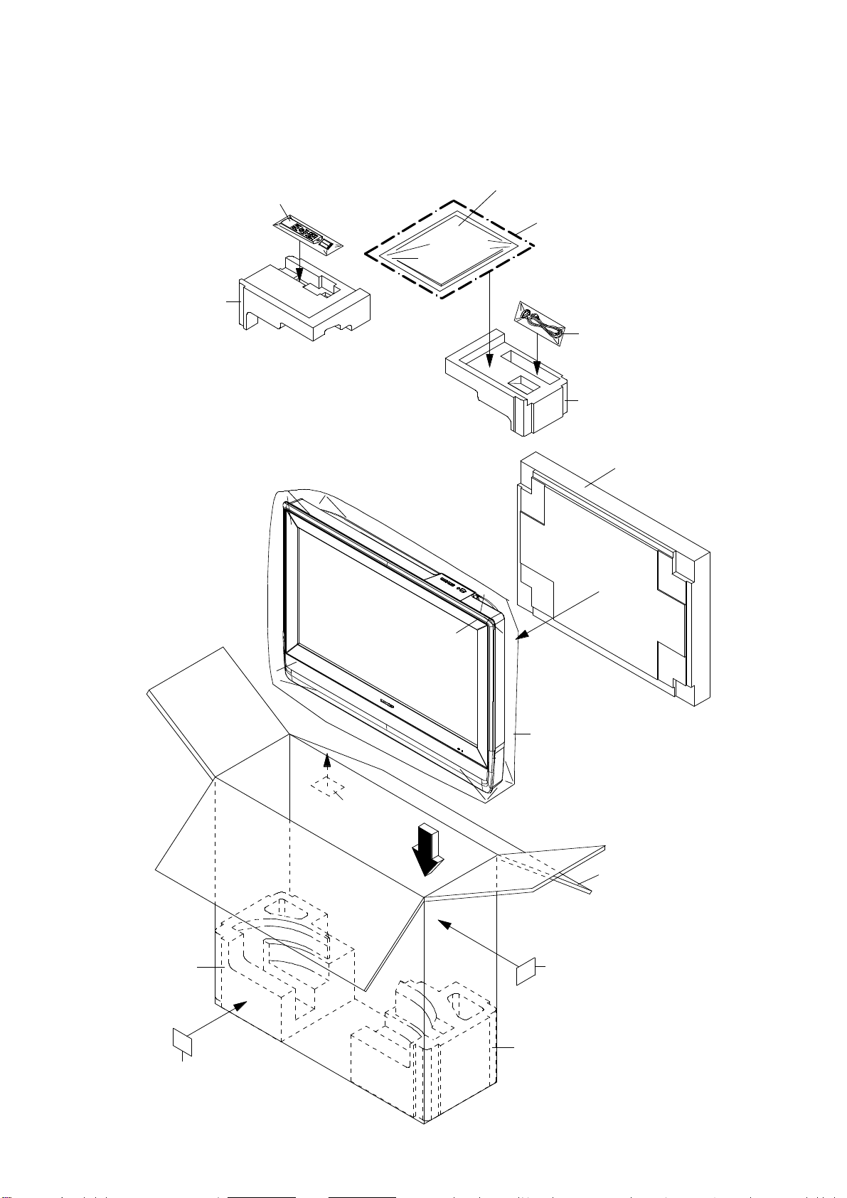
PACKAGE TOP
MECHANICAL EXPLODED VIEW
(PACKING DIAGRAM)
POLYBAG INSTRUCTION,
TM101
INSTRUCTION BOOK (E/F/S),
REGISTRATION CARD
INSTRUCTION BOOK KIT
CD3810
HOLDER CORD
PACKAGE TOP
PACKAGE STAND-TOP
PACKAGE STAND-BOTTOM
PACKING SACK
SCREW
SHEET INFORMATION
PACKAGE BOTTOM
SHEET BARCODE
(7230008184)
SHEET BARCODE
(7230008185)
LAMIFILM BAG
GIFT BOX
SHEET BARCODE
(7230008185)
PACKAGE BOTTOM
J1-3
Page 93

600
DVD DECK EXPLODED VIEW
601
608
CD2001
M2602
605
703
605
703
602
SW2
705
603
AA
607
701
704
PCB640
(SW PCB ASS'Y)
CD2301
702
702
604
606
703
Do not replace the parts. Because,
minute adjustments are needed if
this condition is disassembled
further more.
If the repair is needed, replace the
DVD MECHA ASS'Y.
CLASS
GREASE G-555G
PART NO.
Y315061000
PART NAME
MARK
AA
J2-1
NOTE:
Applying positions AA for the grease are
displayed for this section.
Check if the correct grease is applied for each
position.
Page 94

MECHANICAL REPLACEMENT PARTS LIST
REF. NO. PART NO. DESCRIPTION REF. NO. PART NO. DESCRIPTION
101 7A7010241A FRONT CABI ASS'Y 201 8117540A6U SCREW TAPPING(B0) TRUSS 4x16
101A 701WPJ1457 CABINET FRONT 202 8159130A0S SCREW TAPPING(B) WASHER12 PAN 3x10
101B 702WPBA231 COVER HINGE 203 8110230A4S SCREW TAP TITE(P) BIND 3x14
101C 713WPA0402 GLASS LED 204 8110230A4U SCREW TAP TITE(P) BIND 3x14
101D 7235270026 BADGE BRAND 205 8110630A0U SCREW TAP TITE(P) BRAZIER 3x10
101E 735WPB0342 BUTTON FRAME-TV 206 811063080U SCREW TAP TITE(P) BRAZIER 3x8
101F 735WPB0343 BUTTON FRAME-DVD 207 8109230A0U SCREW TAP TITE(B) BIND 3x10
101G 800WQ0A049 FELT SHEET 208 810923080S SCREW TAP TITE(B) BIND 3x8
101H 800WQ00094 FELT SHEET 209 810923080U SCREW TAP TITE(B) BIND 3x8
101I 83SPN1500W PUSH NUT
102 7A702A234A BACK CABI ASS'Y 211 810723060U SCREW TAP TITE(S) BIND 3x6
102A 702WPJA009 CABINET BACK 212 810A140A0U SCREW WASHER(A) M4x10
102B 704WPB0025 SLOT DVD 213 810A13050U SCREW WASHER(A) M3x5
102C 706WPBA002 COVER CONNECTOR 214 810213080U SCREW PAN M3x8
102D 774WPA0009 HOLDER CORD 215 810223060U SCREW BIND
102E 800WQ0A070 FELT SHEET
102F 800WQ0A110 FELT SHEET --- 7230008196 SHEET BARCODE
102G 800WQ00105 FELT SHEET --- 7290000175 SHEET INFORMATION
103 7A7040019A STAND ASS'Y --- 792WHA0684 PACKAGE TOP
103A 704WPBA012 STAND --- 792WHA0685 PACKAGE BOTTOM
103B 761WSB0043 ANGLE STAND --- 793WCD1779 GIFT BOX
103C 800WFA0063 CUSHION LEG --- A5X204E975 INSTRUCTION BOOK KIT
104 706JSA0015 HINGE ASS'Y --- J5X20431A INSTRUCTION BOOK(E/F/S)
105 702WPBA226 COVER BACK --- JA4ND200 POLYBAG INSTRUCTION(RED CAUTION)
106 7220001228 SHEET SERIAL
107 7225270031 SHEET RATING
108 7230008190 POP LABEL
109 7230008206 SHEET JACK-1
210 8109I30A0U SCREW TAP TITE(B) WH7 3x10
--- 791WHA0130 LAMIFILM BAG
--- J3Y00417A REGISTRATION CARD(SHARP)
110 7230008208 SHEET JACK-2
111 7230008209 SHEET JACK-3
112 7230008228 ENERGY STAR LABEL
113 726000A073 SHEET CAUTION
114 735WEA0004 SHEET,CU
115 744WUA0022 SPRING EARTH
116 752WSA0575 SHIELD SCALER
117 752WSA0589 SHIELD,JACK-1
118 752WSA0590 SHIELD,JACK-2
119 752WSA0607 SHIELD MPEG
120 752WSA0612 SHIELD FFC
121 752WSA0616 SHIELD TRAVERSE
122 753WEA0022 SHEET,CU
123 761WPA0452 HOLDER PCB-TV
124 761WPA0453 HOLDER PCB-DVD
125 761WSA0264 ANGLE HINGE
126 761WSA0394 ANGLE,HANDLE-DVD
127 761WSA0396 COVER,LCD
128 761WSA0401 ANGLE DECK-L
129 761WSA0402 ANGLE DECK-R
130 771WPBA015 PLATE JACK-1
131 771WPBA017 PLATE JACK-3
132 771WPBA018 PLATE JACK-2
133 774WPA0005 HOLDER WIRE-2
134 800WFA0081 CUSHION
135 890MP2401A TAPE 50x35
136 890PS61900 PUSH SPACER
137 8965TS1017 CUSHION 65TS10-10 17.5x20x14
138 8965TS1060 CUSHION W10/H10/L60
139 899EFBA002 WIRING-CLIP
140 8995034000 CORD CLIP UL CO.
K1-1
Page 95

DVD DECK REPLACEMENT PARTS LIST
REF. NO. PART NO. DESCRIPTION
! 600
A5X204E650
DVD MECHA ASS'Y A5X204E650
601
602
603
604
605
606
607
608
701
702
703
704
705
CD2001
CD2301
! M2602
PCB640
SW2
92SBB0033A
92AAA0017A
92P100088A
92P100117A
92P200017A
92P200018A
92P100116A
800WFAA008
92P700007A
814011723U
816112080U
813381750U
811022080U
122J4O1603
122H062102
1515S98004
A5X002C640
0500101036
LOADER SUB ASS'Y DLM1D29-31
FEED RACK ASS'Y
GEAR,MOTOR
GEAR,MIDDLE
INSULATOR, F
INSULATOR, R
GEAR,FEED
CUSHION C
SCREW,GEAR FEED
SCREW,PAN M1.7x2.3 P3
SEMS.TAP TITE(P) PAN W10 2x8
SCREW,T-TITE(B)CAMERA PAN M1.7x5.0 P3
SCREW,TAP TITE(P) BIND 2x8
CORD JUMPER 127000-2933
CORD JUMPER 2H062102
MOTOR BCZ3B05
SW PCB ASS'Y DED020A
PUSH SWITCH ESE22MH22
K2-1
Page 96

ELECTRICAL REPLACEMENT PARTS LIST
REF. NO. PART NO.
REMOCON PCB ASS'Y
*** PCB ***
PCBDA0 A5X204EDA0 REMOCON PCB ASS'Y CEF202A
*** DIODES ***
D2202 0021E9Q010 LED LTL-1BEFJ-002A
*** CONNECTORS ***
CP2201 069S250629 CONNECTOR PCB SIDE A2001WV2-5P
*** OTHERS ***
OS2201 077A033001 REMOTE RECEIVER ROM-V338TAO
SCALER PCB ASS'Y
*** PCB ***
PCBDS0 A5X204EDS0 SCALER PCB ASS'Y CEF170A
*** DIODES ***
D101 DE7RB5R62B DIODE ZENER UDZS5.6B TE-17
D105 DD7R20S300 DIODE SCHOTTKY BARRIER RB520S-30-TE61
D106 DE7RB5R62B DIODE ZENER UDZS5.6B TE-17
D109 DD7R20S300 DIODE SCHOTTKY BARRIER RB520S-30-TE61
D802 DE7RB5R62B DIODE ZENER UDZS5.6B TE-17
D803 DE7RB5R62B DIODE ZENER UDZS5.6B TE-17
D805 DE7RB5R62B DIODE ZENER UDZS5.6B TE-17
D807 DD7R0S3550 DIODE SILICON 1SS355 TE-17
D3206 D28R1QS040 DIODE EC31QS04-TE12L
D3207 D28R1QS040 DIODE EC31QS04-TE12L
D3209 D28R11FS20 DIODE EC11FS2-TE12L
D3600 D28R1QS040 DIODE EC31QS04-TE12L
D3601 DD7R60L400 DIODE SCHOTTKY RB160L-40-TE25
D3602 DE7RB5R62B DIODE ZENER UDZS5.6B TE-17
D3603 DD7R60L400 DIODE SCHOTTKY RB160L-40-TE25
D3606 D28R1QS040 DIODE EC31QS04-TE12L
D3609 DE7RB3R32B DIODE ZENER UDZS3.3B TE-17
D3613 DE7RB3R32B DIODE ZENER UDZS3.3B TE-17
D4301 DE7RB5R62B DIODE ZENER UDZS5.6B TE-17
D4302 DE7RB5R62B DIODE ZENER UDZS5.6B TE-17
D4310 DD7R0S3550 DIODE SILICON 1SS355 TE-17
DESCRIPTION
*** ICS ***
IC101 I56F07158A IC OEC7158A
IC102 I9UF032290 IC PST3229NR
IC103 S5X204EE01 MEMORY DATA AT24C256N-10SU-2.7
IC104 S5X204EE02 MEMORY DATA AT24C256N-10SU-2.7
IC801 I56K07A720 IC R8J66607A72FP
IC2101 IFSK0883C0 IC MST9883C-LF-110
IC3201 I07F0C0WF0 IC BA00BC0WFP-E2
!
IC3202 I07F078200 IC BD7820FP-E2
IC3600 I07F078200 IC BD7820FP-E2
IC3601 S5X204EE05 MEMORY DATA BR24L02F-WE2
IC3602 I07F0C0WF0 IC BA00BC0WFP-E2
IC3603 IG1F090110 IC SII9011CLU
IC3604 I0QJ045800 IC NJM4580M(TE1)
IC3605 IG4F020210 IC CM2021-00TR
IC3607 I1FF043340 IC CS4334-KSZR
IC3608 S5X204EE04 MEMORY DATA BR24L32F-WE2
IC3611 ICMF089E50 IC SST89E58RD2-40-C-TQJE
IC4301 I0UF015010 IC MM1501XNRE
K3-1
Page 97

IC4302 I0UF015010 IC MM1501XNRE
IC4303 I0UF015010 IC MM1501XNRE
IC4304 I0UF015010 IC MM1501XNRE
IC7201 IF8F0385A0 IC ICSV385AGLFT
IC8103 I0UF015010 IC MM1501XNRE
IC8104 I0QF025840 IC NJM2584AM(TE1)
*** TRANSISTORS ***
Q101 TNAAC05002 COMPOUND TRANSISTOR KRC103SRTK
Q104 T2AA5132E0 FET KTK5132E-RTK/P
Q105 TPAAC05002 COMPOUND TRANSISTOR KRA103SRTK
Q106 T2AA5132E0 FET KTK5132E-RTK/P
Q2101 TAAA1504SY TRANSISTOR SILICON KTA1504S_Y_RTK
Q3205 TAAA01664Y TRANSISTOR SILICON KTA1664-Y-RTF/P
!
Q3206 TNAAB05003 COMPOUND TRANSISTOR KRC102SRTK
Q3209 TCAA3875SY TRANSISTOR SILICON KTC3875S_Y_RTK
Q3210 TCAA3875SY TRANSISTOR SILICON KTC3875S_Y_RTK
Q3600 T2AA5132E0 FET KTK5132E-RTK/P
Q3601 TNAAD05001 COMPOUND TRANSISTOR KRC104SRTK
Q3605 T2AA5132E0 FET KTK5132E-RTK/P
Q3606 T2AA5132E0 FET KTK5132E-RTK/P
Q3607 TNAAD05001 COMPOUND TRANSISTOR KRC104SRTK
Q3608 TPAAA05001 COMPOUND TRANSISTOR KRA101SRTK
Q3609 TNAAD05001 COMPOUND TRANSISTOR KRC104SRTK
Q3610 TCAA3875SY TRANSISTOR SILICON KTC3875S_Y_RTK
Q3611 TCAA3875SY TRANSISTOR SILICON KTC3875S_Y_RTK
Q3612 TPAAA05001 COMPOUND TRANSISTOR KRA101SRTK
Q3613 TNAAD05001 COMPOUND TRANSISTOR KRC104SRTK
Q4301 TCAA3875SY TRANSISTOR SILICON KTC3875S_Y_RTK
Q4302 TCAA3875SY TRANSISTOR SILICON KTC3875S_Y_RTK
Q4304 TCAA3875SY TRANSISTOR SILICON KTC3875S_Y_RTK
Q4305 TCAA3875SY TRANSISTOR SILICON KTC3875S_Y_RTK
Q8101 TAAA1504SY TRANSISTOR SILICON KTA1504S_Y_RTK
Q8102 TCAA3875SY TRANSISTOR SILICON KTC3875S_Y_RTK
Q8103 TCAA3875SY TRANSISTOR SILICON KTC3875S_Y_RTK
Q8105 TAAA1504SY TRANSISTOR SILICON KTA1504S_Y_RTK
Q8106 TAAA1504SY TRANSISTOR SILICON KTA1504S_Y_RTK
*** COILS ***
B801 024AC5181J CORE,BEADS BLM18PG181SN1D
B802 024AC5181J CORE,BEADS BLM18PG181SN1D
B803 024HC56005 CORE,BEADS FCM1608CF-600T06
B804 024HC56005 CORE,BEADS FCM1608CF-600T06
B805 024AC5181J CORE,BEADS BLM18PG181SN1D
B2101 024HC56005 CORE,BEADS FCM1608CF-600T06
B3201 024AC5181J CORE,BEADS BLM18PG181SN1D
B3202 024AC5181J CORE,BEADS BLM18PG181SN1D
B3203 024AC5181J CORE,BEADS BLM18PG181SN1D
B3204 024AC5181J CORE,BEADS BLM18PG181SN1D
B3206 024AC5181J CORE,BEADS BLM18PG181SN1D
B3207 024AC5181J CORE,BEADS BLM18PG181SN1D
B3208 024AC5181J CORE,BEADS BLM18PG181SN1D
B3601 024HC51513 CORE,BEADS FCM1608KF-151T06
B3602 024HC51513 CORE,BEADS FCM1608KF-151T06
B3603 024HC51513 CORE,BEADS FCM1608KF-151T06
B3604 024HC51513 CORE,BEADS FCM1608KF-151T06
B3605 024HC51513 CORE,BEADS FCM1608KF-151T06
B3608 024HC56005 CORE,BEADS FCM1608CF-600T06
B3609 024HC56005 CORE,BEADS FCM1608CF-600T06
B3610 024HC56005 CORE,BEADS FCM1608CF-600T06
B3611 024HC51023 CORE,BEADS FCM1608KF-102T02
B3613 024HC51023 CORE,BEADS FCM1608KF-102T02
B3614 024HC51513 CORE,BEADS FCM1608KF-151T06
B3615 024HC51513 CORE,BEADS FCM1608KF-151T06
B4303 024HC56005 CORE,BEADS FCM1608CF-600T06 or
024AC5600E CORE,BEADS BLM18BB600SN1D
B4304 024HC56005 CORE,BEADS FCM1608CF-600T06 or
024AC5600E CORE,BEADS BLM18BB600SN1D
B4305 024HC56005 CORE,BEADS FCM1608CF-600T06 or
024AC5600E CORE,BEADS BLM18BB600SN1D
B4307 0246C51024 CORE,BEADS MMZ1608R102CT
K3-2
Page 98

B4308 0246C51024 CORE,BEADS MMZ1608R102CT
B7201 024HC56005 CORE,BEADS FCM1608CF-600T06
L2101 0216S8220K COIL 22 UH
L2102 0216S8220K COIL 22 UH
L2103 0216S8470K COIL 47 UH
L2106 0216S42R2J COIL 2.2 UH
L2107 0216S8220K COIL 22 UH
L4301 0216S8470K COIL 47 UH
L4306 0216S8220K COIL 22 UH
L4307 0216S8220K COIL 22 UH
L7201 0216S8470K COIL 47 UH
L7202 0216S8470K COIL 47 UH
L7203 0216S8470K COIL 47 UH
L8102 0216S8470K COIL 47 UH
L8104 0216S8470K COIL 47 UH
L8105 0216S8220K COIL 22 UH
*** JACKS ***
J4301 060J431025 RCA JACK MSD-242VA1-03_NI_FE_LF
J4302 060K431027 RCA JACK AV6-57B03-01H
*** CONNECTORS ***
CP101 069S250629 CONNECTOR PCB SIDE A2001WV2-5P
CP102 069S2A0629 CONNECTOR PCB SIDE A2001WV2-10P
CP103 069S270629 CONNECTOR PCB SIDE A2001WV2-7P
CP802 069EVU3030 CONNECTOR PCB SIDE 00_6232_030_006_800+
CP803 069EVT3030 CONNECTOR PCB SIDE 00_6232_029_006_800+
CP2200 069S230629 CONNECTOR PCB SIDE A2001WV2-3P
CP3201 069S2B0629 CONNECTOR PCB SIDE A2001WV2-11P
CP3601 069HYJ3010 CONNECTOR PCB SIDE DC1R019JDA
CP3604 069S290629 CONNECTOR PCB SIDE A2001WV2-9P
CP4302 0694S15017 CONNECTOR PCB SIDE 1-1734344-1
CP4303 069S260629 CONNECTOR PCB SIDE A2001WV2-6P
CP7203 069HVWT04A CONNECTOR PCB SIDE FI-X30S-HF-NPB
*** CRYSTAL & CERAMIC OSCILLATORS ***
X101 100WT01611 CRYSTAL HC-49/U-S
X801 100YT05401 CRYSTAL FCX-03
X3601 100CT01101 CRYSTAL HC-49/U-S
X3602 100DT02801 CRYSTAL SMD-49
*** NETWORKS ***
NR801 110P4000M4 R,NETWORK 4D03WGJ0000T5E
NR802 110P4470M4 R,NETWORK 4D03WGJ0470T5E
NR803 110P4470M4 R,NETWORK 4D03WGJ0470T5E
NR804 110P4470M4 R,NETWORK 4D03WGJ0470T5E
NR805 110P4470M4 R,NETWORK 4D03WGJ0470T5E
NR806 110P4470M4 R,NETWORK 4D03WGJ0470T5E
NR807 110P4470M4 R,NETWORK 4D03WGJ0470T5E
NR808 110P4103M4 R,NETWORK 4D03WGJ0103T5E
NR809 110P4103M4 R,NETWORK 4D03WGJ0103T5E
NR2101 110P4101M4 R,NETWORK 4D03WGJ0101T5E
NR2102 110P4101M4 R,NETWORK 4D03WGJ0101T5E
NR2103 110P4101M4 R,NETWORK 4D03WGJ0101T5E
NR2104 110P4101M4 R,NETWORK 4D03WGJ0101T5E
NR2105 110P4101M4 R,NETWORK 4D03WGJ0101T5E
NR2106 110P4101M4 R,NETWORK 4D03WGJ0101T5E
NR3601 110P4330M4 R,NETWORK 4D03WGJ0330T5E
NR3602 110P4000M4 R,NETWORK 4D03WGJ0000T5E
NR3604 110P4000M4 R,NETWORK 4D03WGJ0000T5E
NR3605 110P4000M4 R,NETWORK 4D03WGJ0000T5E
NR3606 110P4000M4 R,NETWORK 4D03WGJ0000T5E
NR3607 110P4000M4 R,NETWORK 4D03WGJ0000T5E
NR3608 110P4000M4 R,NETWORK 4D03WGJ0000T5E
NR7201 110P4470M4 R,NETWORK 4D03WGJ0470T5E
NR7202 110P4470M4 R,NETWORK 4D03WGJ0470T5E
K3-3
Page 99

*** OTHERS ***
SH4301 126R000038 TERMINAL PIN TP00370-21
SH4302 126R000038 TERMINAL PIN TP00370-21
SH4303 126R000038 TERMINAL PIN TP00370-21
AV PCB ASS'Y
*** PCB ***
PCBD20 A5X204ED20 AV PCB ASS'Y CMF087A
*** RESISTORS ***
R338 R3X28B010J R,METAL OXIDE 1 OHM 3W
!
*** CAPACITORS ***
C339 E61FF3102D CE EEUFM1E102E 1000 UF 25V
C6403 E61FF2102D CE EEUFM1C102B 1000 UF 16V
*** DIODES ***
D301 D1VT001330 DIODE,SILICON 1SS133T-77
D4209 D1VT001330 DIODE,SILICON 1SS133T-77
D6401 D1VT001330 DIODE,SILICON 1SS133T-77
D6402 D28R1QS040 DIODE EC31QS04-TE12L
D6403 D4AT01H3E0 DIODE RECTIFIER 1H3-E
*** ICS ***
IC301 I01FF58910 IC AN5891SA-E1V
IC302 I03SP20520 IC LA42052-E
IC303 I0QF0580V0 IC NJM4580V(TE1)
IC901 I01FF58320 IC AN5832SA-E1V
IC4201 I01F05853B IC AN15853B-E1
IC4202 I0QJ045800 IC NJM4580M(TE1)
IC4203 I0UF015010 IC MM1501XNRE
IC4204 I0UF015010 IC MM1501XNRE
IC6401 I1LF010150 IC AL1015
IC6402 TJ7M50P030 FET RSS050P03_TB
IC6403 I03D979950 IC LA7995M-TLM
*** TRANSISTORS ***
Q301 TCAA3875SY TRANSISTOR SILICON KTC3875S_Y_RTK
Q302 TAAA1504SY TRANSISTOR SILICON KTA1504S_Y_RTK
Q303 TCAA3875SY TRANSISTOR SILICON KTC3875S_Y_RTK
Q304 TCAA3875SY TRANSISTOR SILICON KTC3875S_Y_RTK
Q305 TCAA3875SY TRANSISTOR SILICON KTC3875S_Y_RTK
Q306 TPAAA05001 COMPOUND TRANSISTOR KRA101SRTK
Q709 TCAA3875SY TRANSISTOR SILICON KTC3875S_Y_RTK
Q4201 TCAA3875SY TRANSISTOR SILICON KTC3875S_Y_RTK
Q4202 TCAA3875SY TRANSISTOR SILICON KTC3875S_Y_RTK
Q4203 TCAA3875SY TRANSISTOR SILICON KTC3875S_Y_RTK
Q4204 TCAA3875SY TRANSISTOR SILICON KTC3875S_Y_RTK
Q4205 T2AA5132E0 FET KTK5132E-RTK/P
Q4206 T2AA5132E0 FET KTK5132E-RTK/P
Q4207 TNAAD05001 COMPOUND TRANSISTOR KRC104SRTK
Q4208 TCAA3875SY TRANSISTOR SILICON KTC3875S_Y_RTK
Q4209 TPAAA05001 COMPOUND TRANSISTOR KRA101SRTK
Q4210 TNAAC05002 COMPOUND TRANSISTOR KRC103SRTK
Q4231 TPAAC05002 COMPOUND TRANSISTOR KRA103SRTK
Q4233 TNAAB05003 COMPOUND TRANSISTOR KRC102SRTK
Q6401 TNAAC05002 COMPOUND TRANSISTOR KRC103SRTK
Q6402 TNAAB05003 COMPOUND TRANSISTOR KRC102SRTK
*** COILS ***
B701 024HT03553 CORE,BEADS W5RH3.5X5X1.0
B702 024HT03553 CORE,BEADS W5RH3.5X5X1.0
B6402 024AC5181J CORE,BEADS BLM18PG181SN1D
K3-4
Page 100

B6403 024AC5181J CORE,BEADS BLM18PG181SN1D
B6404 024AC5181J CORE,BEADS BLM18PG181SN1D
L001 02167F150J COIL 15 UH
L002 02167F101J COIL 100 UH
L003 0216S8330K COIL NLCV32T-330K-P F 33 UH
L301 02167F101J COIL 100 UH
L302 02167F150J COIL 15 UH
L703 02167F101J COIL 100 UH
L901 02167F101J COIL 100 UH
L4201 02167F470J COIL 47 UH
L4202 02167F470J COIL 47 UH
L4203 02167F470J COIL 47 UH
L4206 02167F470J COIL 47 UH
L4207 02167F470J COIL 47 UH
L6401 02167E220K COIL TSL0808RA-220K1 R7 22 UH
L6402 021404150M COIL SBPSC-11R310-1 50A 15 UH
*** JACKS ***
J301 060J131016 HEADPHONE JACK MSJ-2000_AG
J701 060R401122 RCA JACK RCA-117-01
J4401 063Y700014 JACK DIN-409B
J4402 060K421056 RCA JACK AV-5A-66H
J4403 060K421058 RCA JACK AV-5A-68H
J4404 060K421057 RCA JACK AV-5A-67H
J4405 060K421056 RCA JACK AV-5A-66H
J4406 060K421058 RCA JACK AV-5A-68H
J4407 060K421057 RCA JACK AV-5A-67H
*** CONNECTORS ***
CP301 069S140419 CONNECTOR PCB SIDE A2502WV2-4P
CP4202 069S250629 CONNECTOR PCB SIDE A2001WV2-5P
CP4203 069EVT3030 CONNECTOR PCB SIDE 00_6232_029_006_800+
CP4204 069EVU3030 CONNECTOR PCB SIDE 00_6232_030_006_800+
CP4401 069S290629 CONNECTOR PCB SIDE A2001WV2-9P
CP6401 069S1E0019 CONNECTOR PCB SIDE A2501WV2-14P
CP6402 069S280629 CONNECTOR PCB SIDE A2001WV2-8P
CP6403 069S2B0629 CONNECTOR PCB SIDE A2001WV2-11P
*** TUNER ***
TU001 0162300048 RF UNIT 115-V-LA35ARH
*** OTHERS ***
SH4201 126R000038 TERMINAL PIN TP00370-21
SH4202 126R000038 TERMINAL PIN TP00370-21
SH4203 126R000038 TERMINAL PIN TP00370-21
SH4204 126R000038 TERMINAL PIN TP00370-21
SH4205 126R000038 TERMINAL PIN TP00370-21
SH4206 126R000038 TERMINAL PIN TP00370-21
POWER PCB ASS'Y
*** PCB ***
PCB240 A5X204E240 POWER PCB ASS'Y CEF198A
*** RESISTORS ***
R3801 RC31X1155J RC RCR60CT52A155J 1.5M OHM 1W
!
R3805 R3X181R22J R,METAL OXIDE 0.22 OHM 1W
!
R3812 R65584101J R,FUSE RNF25R101J 100 OHM 1/4W
!
R3813 R3K58A104J R,METAL OXIDE 100K OHM 2W
!
R3815 R63884102J R,FUSE RF25CL10A102 J 1K OHM 1/4W
!
R3818 R63881R22J R,FUSE RF1CL15AR22J 0.22 OHM 1W
!
R3864 R002T4102J RC 1K OHM 1/4W
*** CAPACITORS ***
C3801 P2122B224M CMP 0.22 UF 275V ECQUL
!
K3-5
 Loading...